R-410A 5330389-YIM-A-0517 MODELS: NL090 - 240, 2-Pipe NM120 - 240, 4-Pipe 7.5 - 20 Ton, 60 Hertz TABLE OF CONTENTS General . . . . . . . . . . . . . . . . . . . . . . . . . . . . . . . . . . . . . . . . . . . . . 2 Safety Considerations . . . . . . . . . . . . . . . . . . . . . . . . . . . . . . . . . . 2 Reference . . . . . . . . . . . . . . . . . . . . . . . . . . . . . . . . . . . . . . . . . 2 Agency Approvals . . . . . . . . . . . . . . . . . . . . . . . . . . . . . . . . . . . . . 2 Inspection . . . . . . . . . . . . . . . . . . . . . . . . . . . . . . . . . . . . . . . . . . . . 2 Nomenclature . . . . . . . . . . . . . . . . . . . . . . . . . . . . . . . . . . . . . . . . . 3 Unit Application Data . . . . . . . . . . . . . . . . . . . . . . . . . . . . . . . . . 4 Physical Data Indoor Unit . . . . . . . . . . . . . . . . . . . . . . . . . . . . . 5 Air Discharge Conversion . . . . . . . . . . . . . . . . . . . . . . . . . . . . . 5 Unit Installation . . . . . . . . . . . . . . . . . . . . . . . . . . . . . . . . . . . . . . . . 7 Location . . . . . . . . . . . . . . . . . . . . . . . . . . . . . . . . . . . . . . . . . . . 7 Rigging. . . . . . . . . . . . . . . . . . . . . . . . . . . . . . . . . . . . . . . . . . . . 7 Clearances . . . . . . . . . . . . . . . . . . . . . . . . . . . . . . . . . . . . . . . . . 7 Mounting . . . . . . . . . . . . . . . . . . . . . . . . . . . . . . . . . . . . . . . . . . 8 Duct Connections . . . . . . . . . . . . . . . . . . . . . . . . . . . . . . . . . . 10 Refrigerant Mains . . . . . . . . . . . . . . . . . . . . . . . . . . . . . . . . . . 10 Expansion Valve Bulb Installation . . . . . . . . . . . . . . . . . . . . . . 12 Liquid Line Solenoids . . . . . . . . . . . . . . . . . . . . . . . . . . . . . . . 12 Air System Adjustment . . . . . . . . . . . . . . . . . . . . . . . . . . . . . . 13 Electrical Connections . . . . . . . . . . . . . . . . . . . . . . . . . . . . . . . 13 IntelliSpeed Communication Wiring. . . . . . . . . . . . . . . . . . . . . 13 IntelliSpeed Programming Guide. . . . . . . . . . . . . . . . . . . . . . . 13 Electrical Data . . . . . . . . . . . . . . . . . . . . . . . . . . . . . . . . . . . . . . . 23 Airflow Performance . . . . . . . . . . . . . . . . . . . . . . . . . . . . . . . . 27 Airflow Performance . . . . . . . . . . . . . . . . . . . . . . . . . . . . . . . . . . . 28 Twin Belt Drive Adjustment . . . . . . . . . . . . . . . . . . . . . . . . . . . 36 Sequence of Operation . . . . . . . . . . . . . . . . . . . . . . . . . . . . . . 37 Maintenance . . . . . . . . . . . . . . . . . . . . . . . . . . . . . . . . . . . . . . . . 39 Typical Wiring Diagrams . . . . . . . . . . . . . . . . . . . . . . . . . . . . . . . 47 Air Handling Units . . . . . . . . . . . . . . . . . . . . . . . . . . . . . . . . . . 47 Start-Up Sheet . . . . . . . . . . . . . . . . . . . . . . . . . . . . . . . . . . . . . . . 54 LIST OF TABLES 1 Air Handling Unit Limitations . . . . . . . . . . . . . . . . . . . . . . . . . . 4 2 Physical Data Indoor Unit . . . . . . . . . . . . . . . . . . . . . . . . . . . . 5 3 Minimum Clearances . . . . . . . . . . . . . . . . . . . . . . . . . . . . . . . . 7 4 Corner Weights & Center of Gravity NL/NM 090 Thru 240 Units . . . . . . . . . . . . . . . . . . . . . . . . . . . . . . . . . . . . . . . . . . . . . 9 5 Standard (Non VFD) & Intellispeed (ISP) Low Voltage Wiring . . . . . . . . . . . . . . . . . . . . . . . . . . . . . . . . . . . . . . . . . . . 14 6 Electrical Data - Evaporator Units . . . . . . . . . . . . . . . . . . . . . 23 7 Altitude/Temperature Correction Factors . . . . . . . . . . . . . . . 26 8 NL090 Upflow . . . . . . . . . . . . . . . . . . . . . . . . . . . . . . . . . . . . 28 9 NL090 Horizontal . . . . . . . . . . . . . . . . . . . . . . . . . . . . . . . . . . 28 10 NL/NM120 Upflow . . . . . . . . . . . . . . . . . . . . . . . . . . . . . . . . . 29 11 NL/NM120 Horizontal . . . . . . . . . . . . . . . . . . . . . . . . . . . . . . 29 12 NL/NM180 Upflow . . . . . . . . . . . . . . . . . . . . . . . . . . . . . . . . . 30 13 NL/NM180 Horizontal . . . . . . . . . . . . . . . . . . . . . . . . . . . . . . 30 14 NL/NM240 Upflow . . . . . . . . . . . . . . . . . . . . . . . . . . . . . . . . . 31 15 NL/NM240 Horizontal . . . . . . . . . . . . . . . . . . . . . . . . . . . . . . 31 16 RPM Selection . . . . . . . . . . . . . . . . . . . . . . . . . . . . . . . . . . . 32 17 Additional Static Resistance . . . . . . . . . . . . . . . . . . . . . . . . . 33 18 Blower Motor And Drive Data . . . . . . . . . . . . . . . . . . . . . . . . 34 19 Piping, Electrical and Duct Opening Connection Sizes . . . . 46 LIST OF FIGURES 1 Vertical Airflow Arrangements . . . . . . . . . . . . . . . . . . . . . . . . 6 2 Horizontal Airflow Arrangements . . . . . . . . . . . . . . . . . . . . . . 6 3 Typical Cabinet Assembly . . . . . . . . . . . . . . . . . . . . . . . . . . . 7 4 Typical Suspension of AHU’s From Ceiling . . . . . . . . . . . . . . 8 5 Suggested Method For Connecting Ductwork . . . . . . . . . . . 10 6 Recommended Drain Piping . . . . . . . . . . . . . . . . . . . . . . . . . 10 7 TVX Bulb Location . . . . . . . . . . . . . . . . . . . . . . . . . . . . . . . . 12 8 Typical Simplified Field Wiring Diagram – NL090 Evaporator with PC090 Heat Pump Condenser . . . . . . . . . . . . . . . . . . . 15 9 Typical Simplified Field Wiring Diagram – NL090 Evaporator . . . . . . . . . . . . . . . . . . . . . . . . . . . . . . . . . . . . . . 15 10 Typical Simplified Field Wiring Diagram – NL120 thru 180 Evaporator with PC120 thru 180 Heat Pump Condenser . . . 16 11 Typical NL120 - 240 Liquid Line Solenoid Wiring . . . . . . . . . 16 12 Typical Simplified Field Wiring Diagram – NL120 thru 180 Evaporator . . . . . . . . . . . . . . . . . . . . . . . . . . . . . . . . . . . . . . 17 13 Typical Simplified Field Wiring Diagram – NM180 thru 240 Evaporator with PD180 thru 240 Heat Pump Condenser . . . 18 14 Typical Simplified Field Wiring Diagram – NM180 thru 240 Evaporator . . . . . . . . . . . . . . . . . . . . . . . . . . . . . . . . . . . . . . 18 15 Typical Simplified Field Wiring Diagram – NL090 Evaporator with YC090 Condenser . . . . . . . . . . . . . . . . . . . . . . . . . . . . . 19 16 Typical Simplified Field Wiring Diagram – NL090 Evaporator . . . . . . . . . . . . . . . . . . . . . . . . . . . . . . . . . . . . . . 19 17 Typical Simplified Field Wiring Diagram – NL120 thru 240 Evaporator with YC120 thru 240 Condenser . . . . . . . . . . . . 20 18 Typical NL120 - 240 Liquid Line Solenoid Wiring . . . . . . . . . 20 19 Typical Simplified Field Wiring Diagram – NL120 thru 240 Evaporator . . . . . . . . . . . . . . . . . . . . . . . . . . . . . . . . . . . . . . 21 20 Typical Simplified Field Wiring Diagram – NM120 thru 240 Evaporator with YD120 thru 240 Condenser . . . . . . . . . . . . 22 21 Typical Simplified Field Wiring Diagram – NM120 thru 240 Evaporator . . . . . . . . . . . . . . . . . . . . . . . . . . . . . . . . . . . . . . 22 22 Altitude/Temperature Correction Factors . . . . . . . . . . . . . . . 26 23 Hole Location For Pressure Drop Reading . . . . . . . . . . . . . 34 24 Pressure Drop Across A Dry Indoor Coil vs. Supply Air CFM . . . . . . . . . . . . . . . . . . . . . . . . . . . . . . . . . . . . . . . . . . . 35 25 Belt Adjustment . . . . . . . . . . . . . . . . . . . . . . . . . . . . . . . . . . 36 26 Double Groove Pulley . . . . . . . . . . . . . . . . . . . . . . . . . . . . . 36 27 Unit Dimensions NL090/120 & NM120 . . . . . . . . . . . . . . . . 40 28 Unit Dimensions NL/NM180 . . . . . . . . . . . . . . . . . . . . . . . . . 42 29 Unit Dimensions NL/NM240 . . . . . . . . . . . . . . . . . . . . . . . . . 44 30 Typical NL090 Wiring Diagram . . . . . . . . . . . . . . . . . . . . . . 47 31 Typical NL120 thru 240, 1.5 Thru 5.0 HP Blower Motor Only Wiring Diagram . . . . . . . . . . . . . . . . . . . . . . . . . . . . . . . . . . 48 32 Typical NL 240, 7.5 HP Blower Motor 208/230 V Only Wiring Diagram . . . . . . . . . . . . . . . . . . . . . . . . . . . . . . . . . . . . . . . . 49 33 Typical NL 240, 7.5 HP Blower Motor 460/575 V Only Wiring Diagram . . . . . . . . . . . . . . . . . . . . . . . . . . . . . . . . . . . . . . . . 50 34 Typical NM120 thru 240, 1.5 Thru 5.0 HP Blower Motor Only Wiring Diagram . . . . . . . . . . . . . . . . . . . . . . . . . . . . . . . . . . 51 35 Typical NM 240, 7.5 HP Blower Motor 208/230 Volt Only Wiring Diagram . . . . . . . . . . . . . . . . . . . . . . . . . . . . . . . . . . . . . . . . 52 36 Typical NM 240, 7.5 HP Blower Motor 460/575 Volt Only Wiring Diagram . . . . . . . . . . . . . . . . . . . . . . . . . . . . . . . . . . . . . . . . 53

Welcome message from author
This document is posted to help you gain knowledge. Please leave a comment to let me know what you think about it! Share it to your friends and learn new things together.
Transcript

R-410A
5330389-YIM-A-0517
MODELS: NL090 - 240, 2-PipeNM120 - 240, 4-Pipe
7.5 - 20 Ton, 60 Hertz
TABLE OF CONTENTSGeneral . . . . . . . . . . . . . . . . . . . . . . . . . . . . . . . . . . . . . . . . . . . . . 2Safety Considerations . . . . . . . . . . . . . . . . . . . . . . . . . . . . . . . . . . 2
Reference . . . . . . . . . . . . . . . . . . . . . . . . . . . . . . . . . . . . . . . . . 2Agency Approvals . . . . . . . . . . . . . . . . . . . . . . . . . . . . . . . . . . . . . 2Inspection . . . . . . . . . . . . . . . . . . . . . . . . . . . . . . . . . . . . . . . . . . . . 2Nomenclature . . . . . . . . . . . . . . . . . . . . . . . . . . . . . . . . . . . . . . . . . 3
Unit Application Data . . . . . . . . . . . . . . . . . . . . . . . . . . . . . . . . . 4Physical Data Indoor Unit . . . . . . . . . . . . . . . . . . . . . . . . . . . . . 5Air Discharge Conversion . . . . . . . . . . . . . . . . . . . . . . . . . . . . . 5
Unit Installation . . . . . . . . . . . . . . . . . . . . . . . . . . . . . . . . . . . . . . . . 7Location . . . . . . . . . . . . . . . . . . . . . . . . . . . . . . . . . . . . . . . . . . . 7Rigging. . . . . . . . . . . . . . . . . . . . . . . . . . . . . . . . . . . . . . . . . . . . 7Clearances. . . . . . . . . . . . . . . . . . . . . . . . . . . . . . . . . . . . . . . . . 7Mounting . . . . . . . . . . . . . . . . . . . . . . . . . . . . . . . . . . . . . . . . . . 8Duct Connections . . . . . . . . . . . . . . . . . . . . . . . . . . . . . . . . . . 10Refrigerant Mains . . . . . . . . . . . . . . . . . . . . . . . . . . . . . . . . . . 10
Expansion Valve Bulb Installation . . . . . . . . . . . . . . . . . . . . . . 12Liquid Line Solenoids . . . . . . . . . . . . . . . . . . . . . . . . . . . . . . . 12Air System Adjustment . . . . . . . . . . . . . . . . . . . . . . . . . . . . . . 13Electrical Connections . . . . . . . . . . . . . . . . . . . . . . . . . . . . . . . 13IntelliSpeed Communication Wiring. . . . . . . . . . . . . . . . . . . . . 13IntelliSpeed Programming Guide. . . . . . . . . . . . . . . . . . . . . . . 13
Electrical Data . . . . . . . . . . . . . . . . . . . . . . . . . . . . . . . . . . . . . . . 23Airflow Performance . . . . . . . . . . . . . . . . . . . . . . . . . . . . . . . . 27
Airflow Performance . . . . . . . . . . . . . . . . . . . . . . . . . . . . . . . . . . . 28Twin Belt Drive Adjustment . . . . . . . . . . . . . . . . . . . . . . . . . . . 36Sequence of Operation . . . . . . . . . . . . . . . . . . . . . . . . . . . . . . 37
Maintenance . . . . . . . . . . . . . . . . . . . . . . . . . . . . . . . . . . . . . . . . 39Typical Wiring Diagrams . . . . . . . . . . . . . . . . . . . . . . . . . . . . . . . 47
Air Handling Units . . . . . . . . . . . . . . . . . . . . . . . . . . . . . . . . . . 47Start-Up Sheet . . . . . . . . . . . . . . . . . . . . . . . . . . . . . . . . . . . . . . . 54
LIST OF TABLES1 Air Handling Unit Limitations . . . . . . . . . . . . . . . . . . . . . . . . . . 42 Physical Data Indoor Unit . . . . . . . . . . . . . . . . . . . . . . . . . . . . 53 Minimum Clearances . . . . . . . . . . . . . . . . . . . . . . . . . . . . . . . . 74 Corner Weights & Center of Gravity NL/NM 090 Thru 240
Units . . . . . . . . . . . . . . . . . . . . . . . . . . . . . . . . . . . . . . . . . . . . . 95 Standard (Non VFD) & Intellispeed (ISP) Low Voltage
Wiring . . . . . . . . . . . . . . . . . . . . . . . . . . . . . . . . . . . . . . . . . . . 146 Electrical Data - Evaporator Units . . . . . . . . . . . . . . . . . . . . . 237 Altitude/Temperature Correction Factors . . . . . . . . . . . . . . . 268 NL090 Upflow . . . . . . . . . . . . . . . . . . . . . . . . . . . . . . . . . . . . 289 NL090 Horizontal . . . . . . . . . . . . . . . . . . . . . . . . . . . . . . . . . . 28
10 NL/NM120 Upflow . . . . . . . . . . . . . . . . . . . . . . . . . . . . . . . . . 2911 NL/NM120 Horizontal . . . . . . . . . . . . . . . . . . . . . . . . . . . . . . 2912 NL/NM180 Upflow . . . . . . . . . . . . . . . . . . . . . . . . . . . . . . . . . 3013 NL/NM180 Horizontal . . . . . . . . . . . . . . . . . . . . . . . . . . . . . . 3014 NL/NM240 Upflow . . . . . . . . . . . . . . . . . . . . . . . . . . . . . . . . . 3115 NL/NM240 Horizontal . . . . . . . . . . . . . . . . . . . . . . . . . . . . . . 3116 RPM Selection . . . . . . . . . . . . . . . . . . . . . . . . . . . . . . . . . . . 3217 Additional Static Resistance . . . . . . . . . . . . . . . . . . . . . . . . . 3318 Blower Motor And Drive Data . . . . . . . . . . . . . . . . . . . . . . . . 3419 Piping, Electrical and Duct Opening Connection Sizes . . . . 46
LIST OF FIGURES1 Vertical Airflow Arrangements . . . . . . . . . . . . . . . . . . . . . . . . 62 Horizontal Airflow Arrangements . . . . . . . . . . . . . . . . . . . . . . 63 Typical Cabinet Assembly . . . . . . . . . . . . . . . . . . . . . . . . . . . 74 Typical Suspension of AHU’s From Ceiling . . . . . . . . . . . . . . 85 Suggested Method For Connecting Ductwork . . . . . . . . . . . 106 Recommended Drain Piping . . . . . . . . . . . . . . . . . . . . . . . . . 107 TVX Bulb Location . . . . . . . . . . . . . . . . . . . . . . . . . . . . . . . . 128 Typical Simplified Field Wiring Diagram – NL090 Evaporator
with PC090 Heat Pump Condenser . . . . . . . . . . . . . . . . . . . 159 Typical Simplified Field Wiring Diagram – NL090
Evaporator . . . . . . . . . . . . . . . . . . . . . . . . . . . . . . . . . . . . . . 1510 Typical Simplified Field Wiring Diagram – NL120 thru 180
Evaporator with PC120 thru 180 Heat Pump Condenser . . . 1611 Typical NL120 - 240 Liquid Line Solenoid Wiring . . . . . . . . . 1612 Typical Simplified Field Wiring Diagram – NL120 thru 180
Evaporator . . . . . . . . . . . . . . . . . . . . . . . . . . . . . . . . . . . . . . 1713 Typical Simplified Field Wiring Diagram – NM180 thru 240
Evaporator with PD180 thru 240 Heat Pump Condenser . . . 1814 Typical Simplified Field Wiring Diagram – NM180 thru 240
Evaporator . . . . . . . . . . . . . . . . . . . . . . . . . . . . . . . . . . . . . . 1815 Typical Simplified Field Wiring Diagram – NL090 Evaporator
with YC090 Condenser . . . . . . . . . . . . . . . . . . . . . . . . . . . . . 1916 Typical Simplified Field Wiring Diagram – NL090
Evaporator . . . . . . . . . . . . . . . . . . . . . . . . . . . . . . . . . . . . . . 1917 Typical Simplified Field Wiring Diagram – NL120 thru 240
Evaporator with YC120 thru 240 Condenser . . . . . . . . . . . . 2018 Typical NL120 - 240 Liquid Line Solenoid Wiring . . . . . . . . . 20
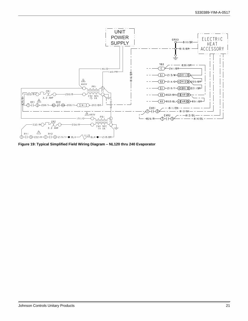
19 Typical Simplified Field Wiring Diagram – NL120 thru 240 Evaporator . . . . . . . . . . . . . . . . . . . . . . . . . . . . . . . . . . . . . . 21
20 Typical Simplified Field Wiring Diagram – NM120 thru 240 Evaporator with YD120 thru 240 Condenser . . . . . . . . . . . . 22
21 Typical Simplified Field Wiring Diagram – NM120 thru 240 Evaporator . . . . . . . . . . . . . . . . . . . . . . . . . . . . . . . . . . . . . . 22
22 Altitude/Temperature Correction Factors . . . . . . . . . . . . . . . 2623 Hole Location For Pressure Drop Reading . . . . . . . . . . . . . 3424 Pressure Drop Across A Dry Indoor Coil vs. Supply Air
CFM . . . . . . . . . . . . . . . . . . . . . . . . . . . . . . . . . . . . . . . . . . . 3525 Belt Adjustment . . . . . . . . . . . . . . . . . . . . . . . . . . . . . . . . . . 3626 Double Groove Pulley . . . . . . . . . . . . . . . . . . . . . . . . . . . . . 3627 Unit Dimensions NL090/120 & NM120 . . . . . . . . . . . . . . . . 4028 Unit Dimensions NL/NM180 . . . . . . . . . . . . . . . . . . . . . . . . . 4229 Unit Dimensions NL/NM240 . . . . . . . . . . . . . . . . . . . . . . . . . 4430 Typical NL090 Wiring Diagram . . . . . . . . . . . . . . . . . . . . . . 4731 Typical NL120 thru 240, 1.5 Thru 5.0 HP Blower Motor Only
Wiring Diagram . . . . . . . . . . . . . . . . . . . . . . . . . . . . . . . . . . 4832 Typical NL 240, 7.5 HP Blower Motor 208/230 V Only Wiring
Diagram . . . . . . . . . . . . . . . . . . . . . . . . . . . . . . . . . . . . . . . . 4933 Typical NL 240, 7.5 HP Blower Motor 460/575 V Only Wiring
Diagram . . . . . . . . . . . . . . . . . . . . . . . . . . . . . . . . . . . . . . . . 5034 Typical NM120 thru 240, 1.5 Thru 5.0 HP Blower Motor Only
Wiring Diagram . . . . . . . . . . . . . . . . . . . . . . . . . . . . . . . . . . 5135 Typical NM 240, 7.5 HP Blower Motor 208/230 Volt Only Wiring
Diagram . . . . . . . . . . . . . . . . . . . . . . . . . . . . . . . . . . . . . . . . 5236 Typical NM 240, 7.5 HP Blower Motor 460/575 Volt Only Wiring
Diagram . . . . . . . . . . . . . . . . . . . . . . . . . . . . . . . . . . . . . . . . 53
5330389-YIM-A-0517
2 Johnson Controls Unitary Products
General
These completely assembled 7-1/2 thru 20 ton evaporator blower units include a well insulated cabinet, a DX cooling coil with copper tubes and aluminum fins, expansion valve(s), dis-tributor(s), throwaway filters, centrifugal blower(s), blower motor, completely wired control box and a small holding charge of dry nitrogen. Blower motors and adjustable drives are fac-tory-installed on all units.
Supplemental resistance heaters, supply air plenums, return air grills, hot water coils, non-freeze steam coils, and bases are available as accessories for field installation.
The units are shipped in the vertical position ready for field installation.
These air handling units are factory equipped with a VFD. The VFD functions in a discrete fan control mode providing multiple speed supply blower fan operation
Safety Considerations
Installer should pay particular attention to the words: NOTE, CAUTION, and WARNING. Notes are intended to clarify or make the installation easier. Cautions are given to prevent equipment damage. Warnings are given to alert installer that personal injury and/or equipment damage may result if installa-tion procedure is not handled properly.
Reference
This instruction covers the installation and operation of evapo-rator blower units. For information on the operation of matching condensing units, refer to Installation Manual - 5184118 for cooling units and Installation Manual - 1192365 for heat pumps.
Additional information on the design, installation, operation and service of this equipment is available in the Technical Guide - 505428.
Renewal Parts
Contact your local Source 1 parts distribution center for autho-rized replacement parts.
Agency Approvals
Design certified by CSA as follows:
1. For use as a (cooling coil, heat pump coil/air handler) only with or without supplemental electric heat.
2. For indoor installation only.
Inspection
As soon as a unit is received, it should be inspected for possible damage during transit. If damage is evident, the extent of the damage should be noted on the carrier’s freight bill. A separate request for inspection by the carrier’s agent should be made in writing.
Improper installation may create a condition where the operation of the product could cause personal injury or property damage.
Improper installation, adjustment, alteration, service or maintenance can cause injury or property damage. Refer to this manual for assistance or for additional information, consult a qualified contractor, installer or service agency.
This system uses R-410A Refrigerant which operates at higher pressures than R-22. No other refrigerant may be used in this system. Gage sets, hoses, refrigerant containers and recovery systems must be designed to handle R-410A. If you are unsure, consult the equipment manufacturer. Failure to use R-410A compatible servicing equipment may result in property damage or injury.
This product must be installed in strict compliance with the enclosed installation instructions and any applicable local, state and national codes including, but not limited to, building, electrical, and mechanical codes.
Wear safety glasses and gloves when handling refrigerants. Failure to follow this warning can cause serious personal injury.
5330389-YIM-A-0517
Johnson Controls Unitary Products 3
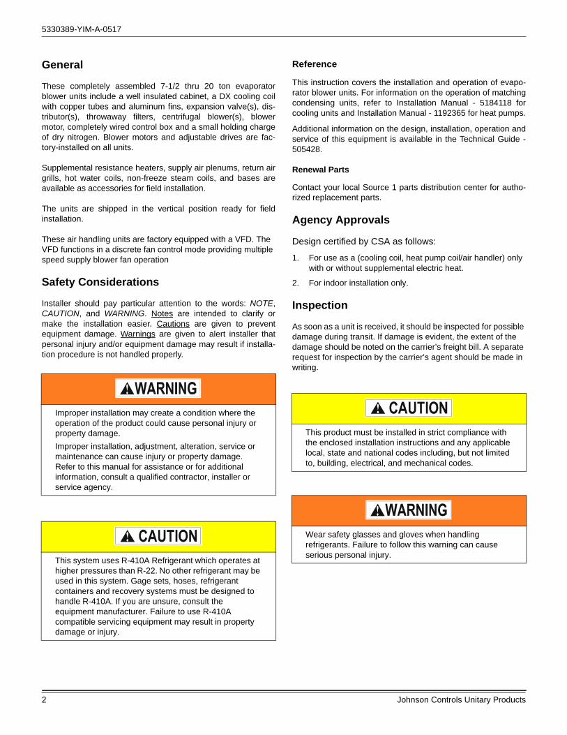
Nomenclature
Product CategoryN = Split System, Air Handler, AC & HP R-410A
Product Identifier
Nominal Cooling Capacity - MBH090 = 7-1/2 Ton120 = 10 Ton180 = 15 Ton240 = 20 Ton
C00 = Cooling Only
Product OptionsAA = No Options InstalledEJ = E-Coat Evaporator CoilTJ = Technicoat Evaporator Coil
Installation Options1
B = IntelliSpeed VFD C = IntelliSpeed VFD w/BypassD = Customer Installed IntelliSpeed VFD
2 = 208/230-3-604 = 460-3-605 = 575-3-60
Configured Split Air Handler Model Number Nomenclature
B = 1.5 HP MotorC = 2.0 HP MotorD = 3.0 HP MotorE = 5.0 HP MotorF = 7.5 HP MotorN = None (Motor Drive Kit Reg)
Airflow
Product Generation1 = First Generation
Voltage
Heat Type & Nominal Heat Capacity
N L 240 C00 B 6 A AA 1 AProduct Style
A = Style A
1. In order for the IntelliSpeed option to function properly some field programming will be required. See unit installation manual for details.
L = Standard Efficiency, 2-pipe w/IntellispeedM = Standard Efficiency, 4-pipe w/Intellispeed

5330389-YIM-A-0517
4 Johnson Controls Unitary Products
Unit Application Data
Table 1: Air Handling Unit Limitations
Model Power Supply VoltageVoltage Variation Supply Air Range CFM
Entering Air Temperature Degrees °F
CoolingDB/WB
Heating DB1
Min. Max. Min. Max. Min. Max. Min. Max.
NL090
208/230-3-60 187 253 2,250 3,750 65/57 90/77 40 80
460-3-60 414 506 2,250 3,750 65/57 90/77 40 80
575-3-60 540 630 2,250 3,750 65/57 90/77 40 80
NL120
208/230-3-60 187 253 3,000 5,000 65/57 90/77 40 80
460-3-60 414 506 3,000 5,000 65/57 90/77 40 80
575-3-60 540 630 3,000 5,000 65/57 90/77 40 80
NM120
208/230-3-60 187 253 3,000 5,000 65/57 90/77 40 80
460-3-60 414 506 3,000 5,000 65/57 90/77 40 80
575-3-60 540 630 3,000 5,000 65/57 90/77 40 80
NL180
208/230-3-60 187 253 4,500 7,500 65/57 90/77 40 80
460-3-60 414 506 4,500 7,500 65/57 90/77 40 80
575-3-60 540 630 4,500 7,500 65/57 90/77 40 80
NM180
208/230-3-60 187 253 4,500 7,500 65/57 90/77 40 80
460-3-60 414 506 4,500 7,500 65/57 90/77 40 80
575-3-60 540 630 4,500 7,500 65/57 90/77 40 80
NL240
208/230-3-60 187 253 6,000 10,000 65/57 90/77 40 80
460-3-60 414 506 6,000 10,000 65/57 90/77 40 80
575-3-60 540 630 6,000 10,000 65/57 90/77 40 80
NM240
208/230-3-60 187 253 6,000 10,000 65/57 90/77 40 80
460-3-60 414 506 6,000 10,000 65/57 90/77 40 80
575-3-60 540 630 6,000 10,000 65/57 90/77 40 80
1. Heating Min/Max temperatures apply to steam and hot water coils. NOTE: Do not apply steam to hot water coils.

5330389-YIM-A-0517
Johnson Controls Unitary Products 5
Physical Data Indoor Unit
Air Discharge Conversion
These units are shipped for Vertical Airflow operation as seen in Figure 1 Position 1, but may be converted to Positions 2 thru 8 as well as for Horizontal Airflow operation illustrated in Figure 2 Positions 1 thru 8.
NOTE: Units that require bottom return conversion for vertical airflow operation Figure 1 positions 5, 6, 7, 8 and horizontal air flow operation Figure 2 positions 5, 6, 7 and 8 require a field installed bottom return kit.
1BP0401 for 7.5 AND 10 TON
1BP0402 for 15 TON
1BP0403 for 20 TON
Conversion Example:
Convert Vertical Airflow Position 1 to Horizontal Airflow Position 1 as follows:
1. Remove the front panel from the blower section and set aside. Save the screws for Step 8.
2. Remove the four bolts that hold the coil section and blower section together. Save the bolts for Step 6.
3. Set the blower section aside.
4. Remove the evaporator section rear panel and set aside. Save the screws for Step 7.
5. Rotate the blower section and mate it to the hole left by removing the panel in Step 4.
6. Bolt the two sections together using the four 3/8” nut inserts provided with the bolts removed in Step 2.
7. Place the panel removed in Step 4 on top of the evaporator section and screw together.
8. Replace the panel removed in Step 1 on the blower section and screw together.
Table 2: Physical Data Indoor Unit
ComponentModels
NL090 NL120 NM120 NL180 NM180 NL240 NM240
Nominal Tonnage 7 1/2 10 10 15 15 20 20
DIMENSIONS (inches)
Length 56.0 56.0 56.0 74.5 74.5 98.5 98.5
Width 30.0 30.0 30.0 33.0 33.0 30.0 30.0
Height 65.0 65.0 65.0 75.0 75.0 65.0 65.0
WEIGHTS (lb)
Unit Shipping Standard Motor & Drive 542 586 588 794 794 932 932
Unit Shipping High Static Motor & Drive 549 597 599 850 850 963 963
Unit Operating With Standard Motor& Drive 516 563 565 762 762 897 897
Unit Operating With High Static Motor & Drive 523 574 576 788 788 928 928
INDOOR BLOWER (Forward Curve)
Diameter x Width 12 x 12 15 x 15 15 x 15 18 x 18 18 x 18 15 x 15 15 x 15
Quantity 1 1 1 1 1 2 2
INDOOR COIL
Face area (Sq. Ft.) 10.6 10.6 10.6 18.3 18.3 20.0 20.0
Rows 3 4 4 4 4 4 4
Fins per inch 15 15 15 15 15 15 15
Tube diameter 3/8 3/8 3/8 3/8 3/8 3/8 3/8
Circuitry Type Interlaced Interlaced Interlaced Interlaced Interlaced Interlaced Interlaced
Refrigerant Control TXV TXV TXV TXV TXV TXV TXV
SYSTEM DATA
No. Refrigeration Circuits 1 1 2 1 2 1 2
Suction Line OD (in.) 1 1/8 1 3/8 1 1/8 1 5/8 1 3/8 1 5/8 1 3/8
Liquid Line OD (in.) 5/8 7/8 5/8 7/8 5/8 7/8 7/8
FILTERS
Size and Quantity PerModel (In.)
16 x 25 x 2 4 4 4 --- --- 8 8
20 x 24 x 2 --- --- --- 6 6 --- ---
FACE AREA (SQ. FT.) 11.1 11.1 11.1 20.0 20.0 22.2 22.2
Size and Quantity PerModel (In.)
16 x 25 x 4 4 4 4 --- --- 8 8
20 x 24 x 4 --- --- --- 6 6 --- ---
FACE AREA (SQ. FT.) 11.1 11.1 11.1 18.0 18.0 22.2 22.2

5330389-YIM-A-0517
6 Johnson Controls Unitary Products
Figure 1: Vertical Airflow Arrangements
Figure 2: Horizontal Airflow Arrangements
BLOWER
EVAPORATOR COILPOSITION
1POSITION
2POSITION
3POSITION
4
POSITION 5
POSITION 6
POSITION 7
POSITION 8
POSITION1
POSITION2
POSITION3
POSITION4
POSITION5
POSITION6
POSITION7
POSITION8

5330389-YIM-A-0517
Johnson Controls Unitary Products 7
Figure 3: Typical Cabinet Assembly
Unit Installation
Location
This split system evaporator unit is not designed for outdoor installation. It must be located inside a building structure, either inside or outside the conditioned space where it is protected from rain and other moisture.
The unit should be located as close to the condenser unit/heat pump as practical and positioned to minimize bends in the refrigerant piping.
This unit can be installed vertically or horizontally and can be set directly on a floor or platform, or supported by metal or wooden beams.
Rigging
Care must be taken when moving the unit. Do not remove any packaging until the unit is near the place of installation. SPREADER BARS SHOULD BE USED BETWEEN THE SLINGS TO PREVENT CRUSHING THE UNIT FRAME OR PANELS. When preparing to move the unit, always determine the center of gravity of the unit in order to equally distribute the weight. Rig the unit by attaching chain or cable slings around the bottom skid. A lift truck may be used to raise a unit to a suspended location. Refer to Table 4 for unit weights.
Clearances
NOTE: If the coil has to be removed, the blower section can be unbolted and set aside and the coil can be lifted out the top of the evaporator section.
MOTOR ACCESSPANEL
BLOWER SECTION
1” X 1/8” THK.GASKET
CONTROLBOX
ELECTRICALPANEL
3/8-16 X 1-1/2” LG. BOLT3/8” LOCK-WASHER3/8” FLAT WASHER3/8-16 X 1-1/2” LG. BOLT
3/8” LOCK-WASHER3/8” FLAT WASHER
3/8-16 NUT-SERT(VERTICAL INSTALLATION)
COIL SECTION
3/8-16 NUT-SERT(HORIZONTALINSTALLATION)
3/8-16 NUT-SERT(VERTICAL
INSTALLATION)
Table 3: Minimum Clearances
Minimum Clearances
Top with Supply Air Opening1
1. This dimension will vary if an electric heater, a supply air plenum or a base is used.
24”
Front with Return Air Opening 24”
Right Side with Access for Piping, Power & Control Wiring Connections2
2. This dimension is required for normal installation and service.
24”
Left Side 24”
Rear3
3. Although no clearance is required for service and operation, some clearance may be required for routing the power and control wiring.
N/A
Bottom4
4. Allow enough clearance to trap the condensate drain line.
N/A

5330389-YIM-A-0517
8 Johnson Controls Unitary Products
Mounting
The split system evaporator unit can be applied in various horizontal positions. Figure 4 shows recommended suspension rigging using properly sized all-thread and metal c-channel. All
components to suspend the unit must be field supplied. Please refer to the unit’s total weight, center of gravity and corner weights (Horizontal position) shown in the appropriate table for proper support sizing.
Figure 4: Typical Suspension of AHU’s From Ceiling
END VIEW
SIDE VIEW
All Thread Steel Rod
Mounting Bracket
Steel C-channel
Flat Washer / Lock Washer
and Nut
MOUNTING DETAIL

5330389-YIM-A-0517
Johnson Controls Unitary Products 9
Table 4: Corner Weights & Center of Gravity NL/NM 090 Thru 240 Units
ModelDrive
OptionShipping
Wt (lb)Operating
Wt (lb)Center of Gravity 4 point Load Location (lb) 6 point Load Location (lb)
CG X CG Y A B C D A B C D E F
Vertical Airflow
NL090Std. Mtr. and Drv. 542 516 16.2 26.5 113 132 146 125 73 81 90 100 90 81
High Static Mtr. and Drv. 549 523 16.2 26.5 114 133 148 127 74 82 91 102 91 83
NL120Std. Mtr. and Drv. 586 563 15.4 26.6 130 138 152 143 86 89 93 102 98 95
High Static Mtr. and Drv. 597 574 15.4 26.6 132 140 155 146 87 91 94 104 100 97
NM120Std. Mtr. and Drv. 588 565 15.4 26.8 131 139 152 143 87 90 94 102 98 94
High Static Mtr. and Drv. 599 576 15.4 26.8 133 141 155 146 88 92 95 104 100 96
NL180Std. Mtr. and Drv. 794 762 17.9 34.3 161 191 223 188 104 116 131 153 136 122
High Static Mtr. and Drv. 820 788 17.9 34.3 166 197 231 195 108 120 135 158 141 126
NM180Std. Mtr. and Drv. 794 762 17.9 34.3 161 191 223 188 104 116 131 153 136 122
High Static Mtr. and Drv. 820 788 17.9 34.3 166 197 231 195 108 120 135 158 141 126
NL240Std. Mtr. and Drv. 932 897 15.7 42.4 184 202 267 244 121 128 136 180 170 160
High Static Mtr. and Drv. 963 928 15.6 42.3 191 207 276 254 125 132 140 187 176 167
NM240Std. Mtr. and Drv. 932 897 15.7 42.4 184 202 267 244 121 128 136 180 170 160
High Static Mtr. and Drv. 963 928 15.6 42.3 191 207 276 254 125 132 140 187 176 167
Horizontal Airflow
NL090Std. Mtr. and Drv. 542 516 30.6 26.5 120 125 138 133 79 82 84 93 91 88
High Static Mtr. and Drv. 549 523 30.8 26.5 121 127 141 134 80 83 86 95 92 89
NL120Std. Mtr. and Drv. 586 563 30.5 26.6 132 136 150 145 87 89 91 101 98 96
High Static Mtr. and Drv. 597 574 30.8 26.6 133 140 155 147 88 91 94 104 100 97
NM120Std. Mtr. and Drv. 588 565 30.5 26.8 133 137 150 145 88 90 92 100 98 96
High Static Mtr. and Drv. 599 576 30.7 26.8 134 141 154 147 89 92 95 104 100 97
NL180Std. Mtr. and Drv. 794 762 33.7 34.3 172 179 210 201 114 117 121 141 137 133
High Static Mtr. and Drv. 820 788 34.3 34.3 174 189 221 204 115 121 127 149 142 135
NM180Std. Mtr. and Drv. 794 762 33.7 34.3 172 179 210 201 114 117 121 141 137 133
High Static Mtr. and Drv. 820 788 34.3 34.3 174 189 221 204 115 121 127 149 142 135
NL240Std. Mtr. and Drv. 932 897 30.5 42.4 190 196 259 251 126 129 131 174 170 167
High Static Mtr. and Drv. 963 928 30.9 42.3 193 205 273 257 127 133 138 184 176 169
NM240Std. Mtr. and Drv. 932 897 30.5 42.4 190 196 259 251 126 129 131 174 170 167
High Static Mtr. and Drv. 963 928 30.9 42.3 193 205 273 257 127 133 138 184 176 169
CG
LENGTH
WIDTH
A
D
FRONT REAR
LEFT
RIGHT
DIM X
DIM Y
B
C
A B C
DEF
VERTICAL POSITION
CG
DIM X
DIM Y
LENGTH
WIDTH
A
D
FRONT REAR
LEFT
RIGHT
B
C
A B C
DEF
HORIZONTAL POSITION

5330389-YIM-A-0517
10 Johnson Controls Unitary Products
Duct Connections
Ductwork should always be suspended with hangers or supported by legs. It should never be fastened directly to the building structure.
Allow clearance around ducts for safety in the handling of heated air and for insulation when required.
Insulation
Ductwork insulation should meet the following criteria:
• Be used when ducts pass through an unconditioned space in the cooling season or through an unheated space during the heating season.
• Include a vapor barrier around the outside to prevent the absorption of moisture.
• Be no less than 2 inches thick with a weatherproof coating when applied to ducts exposed to outdoor conditions.
Supply Air Ducts
See Figure 5 for suggested method of connecting supply air ductwork. Non-flammable material collars should be used to minimize the transmission of noise and/or vibration.
Figure 5: Suggested Method For Connecting Ductwork
Drain Connections
All drain lines MUST be trapped and located so they will not be exposed to freezing temperatures.
All evaporator blower units have a 3/4” ABS condensate stub at the end of a double sloped drain pan. The drain pan is removable and reversible, It can be unscrewed and slid out from one side of the evaporator section and installed in the other end.
NOTE: Consult local plumbing codes for type of glue required for drain connection.
Drain piping should be constructed as shown in Figure 6. The 3-inch dimension must equal or exceed the negative static pressure developed by the supply air blowers. If it does not, the condensate will not drain properly and may overflow the drain pan.
Figure 6: Recommended Drain Piping
Refrigerant Mains
Line Sizing
When sizing refrigerant pipe for a split-system air conditioner, check the following:
1. Suction line pressure drop due to friction.
24"
AIROUTLET
BLOWERGASKETS(BY INSTALLER)
FLANGED DUCTCONNECTION(Factory Furnished,Field Installed )
NON-FLAMMABLECOLLAR
DUCTTRANSITION
DUCT
This Split-System (Air Condensing / Heat Pump / Air Handling) unit is one component of an entire system. As such it requires specific application considerations with regard to the rest of the system (air handling unit, duct design, condensing unit, refrigerant piping and control scheme).
Failure to properly apply this equipment with the rest of the system may result in premature failure and/or reduced performance / increased costs. Warranty coverage specifically excludes failures due to improper application and Unitary Products specifically disclaims any liability resulting from improper application.
Please refer to the equipment Technical Guide, Installation Manual and the piping applications bulletin 247077 or call the applications department for Unitary Products @ 1-877-UPG-SERV for guidance.
3" MINIMUM
¾” ABS STUB
FIELD SUPPLIED
5330389-YIM-A-0517
Johnson Controls Unitary Products 11
2. Liquid line pressure drop due to friction.
3. Suction line velocity for oil return.
4. Liquid line pressure drop due to vertical rise. For certain piping arrangements, different sizes of suction line pipe may have to be used. The velocity of the refrigerant vapor must always be great enough to carry the oil back to the compressor.
5. Evaporator Located Below Condenser - On a split system where the evaporator blower is located below the condenser, the suction line must be sized for both pressure drop and for oil return.
6. Condenser Located Below Evaporator - When the condenser is located below the evaporator blower, the liquid line must be designed for the pressure drop due to both friction loss and vertical rise. If the pressure drop due to vertical rise and friction exceeds 60 psi, some refrigerant will flash before it reaches the thermal expansion valve.
Flash gas:
1. Increases the liquid line pressure loss due to friction that in turn causes further flashing.
2. Reduces the capacity of the refrigerant control device which starves the evaporator.
3. Erodes the seat of the refrigerant control device.
4. Causes erratic control of the refrigerant entering the evaporator.
Take Adequate Precautions
Many service problems can be avoided by taking adequate precautions to provide an internally clean and dry system and by using procedures and materials that conform to established standards.
Use hard drawn copper tubing where no appreciable amount of bending around pipes or other obstructions is necessary. If soft copper is used, care should be taken to avoid sharp bends that may cause a restriction. Pack fiberglass insulation and a sealing material such as permagum around refrigerant lines where they penetrate a wall to reduce vibrations and to retain some flexibility.
Support all tubing at minimum intervals with suitable hangers, brackets or clamps.
Braze all copper-to-copper joints with Silfos-5 or equivalent brazing material. Do not use soft solder. Insulate all suction lines with a minimum of 1/2" ARMAFLEX or equivalent that meets local code. Liquid lines exposed to direct sunlight and/or high temperatures must also be insulated. Never solder suction and liquid lines together. They can be taped together for convenience and support purposes, but they must be completely insulated from each other.
Before beginning installation of the main lines, be sure that the evaporator section has not developed a leak in transit. Check pressure at the Schrader valve located on the header of each coil. If pressure still exists in the system, it can be assumed to
be leak free. If pressure DOES NOT exist the section will need to be repaired before evacuation and charging is performed.
A filter-drier MUST be field-installed in the liquid line of every system to prevent dirt and moisture from damaging the system. Properly sized filter-driers are shipped with each condensing section.
NOTE: Installing a filter-drier does not eliminate the need for the proper evacuation of a system before it is charged.
A field-installed moisture indicating sight-glass should be installed in the liquid line(s) between the filter-drier and the evaporator coil. The moisture indicating sight-glass can be used to check for excess moisture in the system.
The evaporator coil has copper sealing disks brazed over the ends of the liquid and suction connections. The temperature required to make or break a brazed joint is high enough to cause oxidation of the copper unless an inert atmosphere is provided.
NOTE: Dry nitrogen should flow through the system at all times when heat is being applied and until the joint has cooled. The flow of nitrogen will prevent oxidation of the copper lines during installation.
Always punch a small hole in sealing disks before unbrazing to prevent the pressure in the line from blowing them off. Do not use a drill as copper shavings can enter system.
NOTE: Solenoid and hot gas bypass valves (if used) should be opened manually or electrically during brazing or evacuating.
NOTE: Schrader valves located on unit service valves should have their stem removed during brazing to prevent damage to the valve.
Start Installation
Start Installation of main lines at the condenser unit. Verify the service valves are fully seated by screwing the stem of both valves down into the valve body until it stops. Remove the Schraded valve stem and connect a low-pressure nitrogen source to the service port on the suction line valve body. Punch a small hole in the sealing disk; the flow of nitrogen will prevent any debris from entering the system. Wrap the valve body with a wet rag to prevent overheating during the brazing process. Overheating the valve will damage the valve seals. Unbraze the sealing disk, cool the valve body and prepare the joint for connections of the main lines. Repeat for the liquid line valve body.
Never remove a cap from an access port unless the valve is fully back-seated with its valve stem in the maximum counter-clockwise position because the refrigerant charge will be lost. Always use a refrigeration valve wrench to open and close these service valves.

5330389-YIM-A-0517
12 Johnson Controls Unitary Products
Connect the main liquid line to the liquid line connection on the condenser unit, while maintaining a flow of nitrogen. Cool the valve body and replace the Schraded valve stem on the service port of the liquid line service valve.
Install the liquid line from the condenser unit to the evaporator liquid connection, maintaining a flow of nitrogen during all brazing operations.
The filter-drier and sight glass must be located in this line, leaving the O.D. unit.
Connect a low-pressure nitrogen source to the Schrader valve located on the evaporator section coil headers. Punch a small hole in the sealing disks, the flow of nitrogen will prevent any debris from entering the system. Unbraze both liquid and suction sealing disks and prepare the joints for connections of the main lines.
Connect the main liquid line to the liquid line connection on the evaporator section, while maintaining a flow of nitrogen.
Make the suction line connection at the evaporator and run the line to the condenser unit. Connect the main suction line to the suction line connection on the condenser unit, while maintaining a flow of nitrogen. Cool the valve body and replace the Schrader valve stem on the service port of the liquid line service valve.
Once the brazing process is complete, leak testing should be done on all interconnecting piping and the evaporator before proper evacuation to 500 microns is performed. Once the line set and evaporator section is properly evacuated the service valves can be opened and the condensing unit is now ready to charge with the appropriate weight of refrigerant.
NOTE: This instruction covers the installation and operation of the basic air handling unit. For refrigerant piping installation instructions refer to document 247077 "Application Data - General Piping Recommendations for Split System Air Conditioning and Heat Pumps".
Expansion Valve Bulb Installation
Thermal expansion valve bulbs are not factory-installed in their final locations. They are only temporarily secured for shipment. Thermal expansion valve bulbs are equipped with 60" capillary tubes to allow placement of the bulbs anywhere along the suction line; even outside the unit. Do not attempt to install the TXV bulb(s) until all other piping connections are complete.
NL090-240 Models
After all piping connections are made, the expansion valve bulbs may be mounted outside the unit by pulling them through the slotted bushing located on the patch plate and placed on the common suction line (See Figure 7). First, remove the bushing and slide the capillary tubes through the slot toward the center of the bushing. Reinsert the bushing, then fasten both bulbs in the 4 o'clock and/or 8 o'clock position using the bulb clamps provided. Insulate the bulbs to ensure proper valve operation.
NM120-240 Models
After all piping connections are made, fasten the expansion valve bulb from System 1 to the corresponding suction line in a 4 o'clock or 8 o'clock position using one of the bulb clamps provided. Repeat the procedure for System 2. Expansion valve bulbs may be mounted outside the unit by pulling them through the slotted bushing located on the patch plate and placed on the matching system suction line. Insulate the bulbs to ensure proper valve operation.
Figure 7: TVX Bulb Location
Liquid Line Solenoids
The NL120-240 units are shipped with factory installed, normally closed, liquid line solenoid valves on the second stage
This system uses R-410A Refrigerant which operates at higher pressures than R-22. No other refrigerant may be used in this system. Gage sets, hoses, refrigerant containers and recovery systems must be designed to handle R-410A. If you are unsure, consult the equipment manufacturer. Failure to use R-410A compatible servicing equipment may result in property damage or injury.
Wear safety glasses and gloves when handling refrigerants. Failure to follow this warning can cause serious personal injury.
Ensure the TXV bulbs are not crossed between systems. Undesirable performance and possible compressor damage may occur.
Suction Line
Liquid Line TXV Bulb

5330389-YIM-A-0517
Johnson Controls Unitary Products 13
system. When the solenoid coil is energized with a 24-volt signal, the valve will open.
During brazing operations, the valves should be placed in the OPEN position by removing the stem cap with a 9/16” wrench, then rotating the exposed valve stem inward (CLOCKWISE), approximately 10-12 full turns (from the fully CLOSED position), using a 4” adjustable wrench.
The valve stems should be returned to the CLOSED (COUNTER-CLOCKWISE) position prior to the unit’s operation.
Air System Adjustment
Refer to Tables 8 thru 18 to adjust the air system.
Electrical Connections
The electric box ships complete with contractor, transformer, relays, circuit breaker and terminal block for making field connections.
Refer to Typical Unit Wiring Diagrams.
Install a power supply to meet the electrical requirements listed in Table 6.
Provide a disconnect switch and fusing as required.
Install interconnecting control wiring between condensing section, evaporator system and room thermostat.
IntelliSpeed Communication Wiring
Installation of interconnecting Intellispeed VFD wiring and Smart Equipment Controller (SEC) programming will be required to achieve proper discrete fan (Fixed Variable) control operation. There are two different VFD factory options available: Non-bypass and manual Bypass Switch (BPS).
All wiring connections should be made in accordance with National Electric Code (N.E.C), ANSI/NFPA No. 70-Latest Edition and Canadian Electric Code, CSA C22.1.
1. Remove the units' blower access panels, the main control box cover, and the VFD control box cover.
2. Install the electrical service entry conduit (for control and power wiring) into the unit roof knockouts (KOs) in the top of the blower cabinet.
A total of three (3) interconnecting communication wires, (1) ground wire, (1) hot wire and five to six (5-6) control wires must be field supplied and pulled between the indoor & outdoor units depending on the model.
NOTE: THIS WIRE COUNT DOES NOT INCLUDE THE THERMOSTAT WIRING BETWEEN THE OD UNIT AND THERMOSTAT (7 wire minimum).
Maximum communication and control wiring distance with respect to the IntelliSpeed VFD option is 200 feet. VFD control wiring must be foil shielded cable using three-wire #18 AWG Manhattan brand/CDT #M244826 (plenum wire) Belden brand or other equivalent cabling is also acceptable. The control/
thermostat wiring does not require shielding or grounding but #18 AWG minimum wire size is recommended.
Three communication wires and one hot and one ground wire will need to connect between the outdoor unit and the indoor air handler. The connection details for each size of air handler are detailed within this document. Figures 8, 10, 13, 15, 17 and 20 depict simple low voltage and communication wiring; whereas unit wiring diagrams Figures 30-36 provide detailed information about high voltage, low voltage and communication wiring.
To properly connect the IntelliSpeed with VFD communication wiring the following steps must be taken.
3. Using the #18 AWG foil wrapped, shielded communication cable specified above connect to the wiring harness shipped with the outdoor condensing unit or heat pump and run the communication cabling to the indoor air handler following proper communication wiring codes. NOTE: Avoid running the communication wiring near any lighting, high voltage or any electrical device that may introduce noise into the communication wiring. Utilize the 1” knockout on the top of the air handler and one of the 1 1/4" knockout(s) on the OD unit to run the communication and control wiring in ¾" conduit.
4. Connect the 12" long, 3 pin wiring harness (Shipped with the indoor unit) to the Unit Control Board (UCB) found in the OD unit. Plug the harness connector into P5 and connect communication cabling between the OD and ID units as follows:
5. Connect wire #903/Y (VFD FLT) and run to terminal 2 located on TB5 in the indoor air handler.
6. Connect wire #902/W (VFD) and run to terminal 3 located on TB5 in the indoor air handler.
7. Connect wire #901/BK (C) and run to terminal 4 located on TB5 in the indoor air handler.
8. Route a field supplied 24 volt supply wire from TB3-1 on the outdoor unit and run to terminal 1, TB5 on the indoor air handler.
9. Locate the drain wire within the communication cable and connect to green ground terminal inside the OD unit.
10. Replace the units control box cover and outer panels, once all communication, control and power wiring is complete.
IntelliSpeed Programming Guide
Setting up UCB control to operate the fan in "Fixed Variable" or IntelliSpeed mode
The outdoor unit's UCB or Smart Equipment Controller (SEC) will need some minor programming changes in order to operate the indoor unit equipped with the IntelliSpeed VFD in the discrete fan (Fixed Variable) mode.
Follow all lockout, tag out procedures before removing the electrical box access panels. Access the UCB board mounted in the outdoor unit by removing the electrical box access panel. The control box will have a secondary cover that will also need

5330389-YIM-A-0517
14 Johnson Controls Unitary Products
to be removed. Once panels are removed the unit can be energized powering up the unit and UCB board.
1. Access the joystick on the UCB and scroll down from the home screen until the cursor appears next to the "Summary" screen.
2. Hit enter and scroll the cursor down to "Fan" then "FanCtl-Type" hit enter. The screen will display a scrolling "FanCtl-Type" with "Single Speed".
3. Push the joystick cursor left or right and the screen will begin to flash, once the screen is flashing push the joystick left or right until "Fixed Variable" appears, hit enter. The UCB is now programmed to provide a fixed variable output (2-10 VDC) signal to the VFD mounted in the air handler.
Setting up UCB control to operate a single stage YC/PC090 with an NL090 in two stage mode
NL090 indoor units matched with outdoor unit models YC090 or PC090 must be setup for two stage cooling operation. The following steps will outline the procedures to make these minor changes to the Smart Equipment Controller (UCB) mounted in the outdoor unit.
1. Access the joystick on the UCB and scroll down from the home screen until the cursor appears next to the "Details" screen.
2. Hit enter and scroll down to the "Service" screen, hit enter.
3. Scroll down to the "Factory" screen, hit enter.
4. Scroll to the "Standard" screen, hit enter.
5. Scroll to the "ClgStgs" screen, hit enter.
6. The number of cooling stages will be displayed. On an YC090 or PC090 the default should display "1". Push the joystick left or right to change the cooling stages to "2" and push enter. The UCB is now programmed to operate in the two stage cooling mode.
Table 5: Standard (Non VFD) & Intellispeed (ISP) Low Voltage Wiring
Distance from OD to Gauge
ID unit (one way), feet
50 #20
75 #20
100 #20
150 #18
200 #18
250 #16

5330389-YIM-A-0517
Johnson Controls Unitary Products 15
Figure 8: Typical Simplified Field Wiring Diagram – NL090 Evaporator with PC090 Heat Pump Condenser
Figure 9: Typical Simplified Field Wiring Diagram – NL090 Evaporator
C S1 S2 G1 G2 66 60 X
C S1 S2 G1 G2 66 60 X
SE CONTROL BOARD THERMOSTAT CONNECTIONSTB2
TB2
CONDENSER CONTROL BOX
EVAPORATOR CONTROL BOX
THERMOSTATSINGLE STAGE COMP, TWO STAGE FAN
TWO STAGE HEAT
Note: Do Not Use a heat Pump Thermostat
UCBVFD COMM
TB5
TB3-1
VFDVLT VFD C
1
2
3
4
W1 W2 Y1 G Y2 0CC CX R SD-24
R C Y1 Y2 G W1 W2
UNITPOWERSUPPLY

5330389-YIM-A-0517
16 Johnson Controls Unitary Products
Figure 10: Typical Simplified Field Wiring Diagram – NL120 thru 180 Evaporator with PC120 thru 180 Heat Pump Condenser
Figure 11: Typical NL120 - 240 Liquid Line Solenoid Wiring
C S1 S2 G1 G2 66 60 X
C S1 S2 G1 G2 66 60 X
TB2
TB2
CONDENSER CONTROL BOX
EVAPORATOR CONTROL BOX
THERMOSTATTWO STAGE COOL/FAN
TWO STAGE HEAT
Note: Do Not Use a heat Pump Thermostat
UCBVFD COMM
TB5
VFDVLT VFD C
1
2
3
4
W1 W2 Y1 G Y2 0CC CX R SD-24
SE CONTROL BOARD THERMOSTAT CONNECTIONS
R C Y1 Y2 G W1 W2
TB3-1
219 / Y218 / BR
1LLS
VALVE SYS 2BLK
BLK
C O I L

5330389-YIM-A-0517
Johnson Controls Unitary Products 17
Figure 12: Typical Simplified Field Wiring Diagram – NL120 thru 180 Evaporator
UNITPOWERSUPPLY

UNITPOWERSUPPLY
5330389-YIM-A-0517
18 Johnson Controls Unitary Products
Figure 13: Typical Simplified Field Wiring Diagram – NM180 thru 240 Evaporator with PD180 thru 240 Heat Pump Condenser
Figure 14: Typical Simplified Field Wiring Diagram – NM180 thru 240 Evaporator
C S1 S2 G1 G2 66 60 X
C S1 S2 G1 G2 66 60 X
TB2
TB2
CONDENSER CONTROL BOX
EVAPORATOR CONTROL BOX
THERMOSTATTWO STAGE COOL/FAN
TWO STAGE HEAT
Note: Do Not Use a heat Pump Thermostat
UCBVFD COMM
TB5
VFDVLT VFD C
1
2
3
4
W1 W2 Y1 G Y2 0CC CX R SD-24
SE CONTROL BOARD THERMOSTAT CONNECTIONS
R C Y1 Y2 G W1 W2
TB3-1

UNITPOWERSUPPLY
5330389-YIM-A-0517
Johnson Controls Unitary Products 19
Figure 15: Typical Simplified Field Wiring Diagram – NL090 Evaporator with YC090 Condenser
Figure 16: Typical Simplified Field Wiring Diagram – NL090 Evaporator
CONDENSER CONTROL BOX
EVAPORATOR CONTROL BOX
THERMOSTATSINGLE STAGE COMP
TWO SPEED FANTWO STAGE HEAT
W1 W2 Y1 G Y2 0CC CX R SD-24
SE CONTROL BOARD THERMOSTAT CONNECTIONS
R C Y1 Y2 G W1 W2
UCBVFD COMM
TB5
VFDVLT VFD C
1
2
3
4
C S1 S2 G1 G2 66 60 X
C S1 S2 G1 G2 66 60 X
TB2
TB2
TB3-1

5330389-YIM-A-0517
20 Johnson Controls Unitary Products
Figure 17: Typical Simplified Field Wiring Diagram – NL120 thru 240 Evaporator with YC120 thru 240 Condenser
NOTE: On non NL/NM Evaporator models, isolation relays must be installed to avoid overloading on 75 VA transformers on the condensing unit.
Figure 18: Typical NL120 - 240 Liquid Line Solenoid Wiring
C S1 S2 G1 G2 66 60 X
C S1 S2 G1 G2 66 60 X W1 W2 Y1 G Y2 0CC CX R SD-24
SE CONTROL BOARD THERMOSTAT CONNECTIONSTB2
TB2
CONDENSER CONTROL BOX
EVAPORATOR CONTROL BOX
THERMOSTATTWO STAGE COOL/FAN
TWO STAGE HEAT
R C Y1 Y2 G W1 W2
UCBVFD COMM
TB5
VFDVLT VFD C
1
2
3
4
TB3-1
219 / Y218 / BR
1LLS
VALVE SYS 2BLK
BLK
C O I L
5330389-YIM-A-0517
Johnson Controls Unitary Products 21
Figure 19: Typical Simplified Field Wiring Diagram – NL120 thru 240 Evaporator
UNITPOWERSUPPLY

5330389-YIM-A-0517
22 Johnson Controls Unitary Products
Figure 20: Typical Simplified Field Wiring Diagram – NM120 thru 240 Evaporator with YD120 thru 240 Condenser
NOTE: On non NL/NM Evaporator models, isolation relays must be installed to avoid overloading on 75 VA transformers on the condensing unit.
Figure 21: Typical Simplified Field Wiring Diagram – NM120 thru 240 Evaporator
CONDENSER CONTROL BOX
EVAPORATOR CONTROL BOX
C S1 S2 G1 G2 66 60 X
C S1 S2 G1 G2 66 60 X
TB2
TB2
UCBVFD COMM
TB5
VFDVLT VFD C
1
2
3
4
W1 W2 Y1 G Y2 0CC CX R SD-24
SE CONTROL BOARD THERMOSTAT CONNECTIONS
THERMOSTATTWO STAGE COOL/FAN
TWO STAGE HEAT
R C Y1 Y2 G W1 W2
TB3-1
UNITPOWERSUPPLY

5330389-YIM-A-0517
Johnson Controls Unitary Products 23
Electrical Data
Table 6: Electrical Data - Evaporator Units
Motor HP Power Supply
SupplyBlowerMotor
Electric Heat Option MCA1
(Amps)
Max Fuse2/Breaker3 Size
(Amps)FLA Model KW Stages Amps
NL090 C00B (INTELLISPEED)
1.5
208-3-60 4.3
None --- --- --- 5.4 1510 KW 7.5 1 20.8 31.4 3516 KW 12 2 33.4 47.0 5026 KW 19.5 2 54.2 73.0 8036 KW 27 2 75.1 99.1 100
230-3-60 4.2
None --- --- --- 5.3 1510 KW 10 1 24.1 35.3 4016 KW 16 2 38.5 53.4 6026 KW 26 2 62.5 83.4 9036 KW 36 2 86.6 113.5 125
460-3-60 2.1
None --- --- --- 2.6 1510 KW 10 1 12.0 17.7 2016 KW 16 2 19.2 26.7 3026 KW 26 2 31.3 41.7 4536 KW 36 2 43.3 56.8 60
575-3-60 1.8
None --- --- --- 2.3 1510 KW 10 1 9.6 14.3 1516 KW 16 2 15.4 21.5 2526 KW 26 2 25.0 33.5 3536 KW 36 2 34.6 45.6 50
NL090 (NL/NM) 120 C00C (INTELLISPEED)
2.0
208-3-60 5.8
None --- --- --- 7.3 1510 KW 7.5 1 20.8 33.3 3516 KW 12 2 33.4 48.9 5026 KW 19.5 2 54.2 74.9 8036 KW 27 2 75.1 100.9 110
230-3-60 5.8
None --- --- --- 7.3 1510 KW 10 1 24.1 37.3 4016 KW 16 2 38.5 55.4 6026 KW 26 2 62.5 85.4 9036 KW 36 2 86.6 115.5 125
460-3-60 2.9
None --- --- --- 3.6 1510 KW 10 1 12.0 18.7 2016 KW 16 2 19.2 27.7 3026 KW 26 2 31.3 42.7 4536 KW 36 2 43.3 57.8 60
575-3-60 2.2
None --- --- --- 2.8 1510 KW 10 1 9.6 14.8 1516 KW 16 2 15.4 22 2526 KW 26 2 25.0 34 3536 KW 36 2 34.6 46.1 50

5330389-YIM-A-0517
24 Johnson Controls Unitary Products
(NL/NM) 120, NL/NM) 180 C00D (INTELLISPEED)
3.0
208-3-60 8.3
None --- --- --- 10.4 1510 KW 7.5 1 20.8 36.4 4016 KW 12 2 33.4 52 6026 KW 19.5 2 54.2 78 8036 KW 27 2 75.1 104.1 11050 KW 37.6 2 104.2 140.8 150
230-3-60 8.2
None --- --- --- 10.3 1510 KW 10 1 24.1 40.3 4516 KW 16 2 38.5 58.4 6026 KW 26 2 62.5 88.4 9036 KW 36 2 86.6 118.5 12550 KW 50 2 120.3 130.5 150
460-3-60 4.1
None --- --- --- 5.1 1510 KW 10 1 12 20.2 2516 KW 16 2 19.2 29.2 3026 KW 26 2 31.3 44.2 4536 KW 36 2 43.3 59.3 6050 KW 50 2 60.1 65.3 70
575-3-60 3.2
None --- --- --- 4 1510 KW 10 1 9.6 16 2016 KW 16 2 15.4 23.2 2526 KW 26 2 25 35.3 4036 KW 36 2 34.6 47.3 5050 KW 50 2 48.1 52.1 60
(NL/NM) 180 C00E (INTELLISPEED)
5.0
208-3-60 13.5
None --- --- --- 16.9 2010 KW 7.5 1 20.8 42.9 4516 KW 12 2 33.4 58.5 6026 KW 19.5 2 54.2 84.5 9036 KW 27 2 75.1 110.6 12550 KW 37.6 2 104.2 147.3 150
230-3-60 13.0
None --- --- --- 16.3 2010 KW 10 1 24.1 46.3 5016 KW 16 2 38.5 64.4 7026 KW 26 2 62.5 94.4 10036 KW 36 2 86.6 124.5 12550 KW 50 2 120.3 136.5 150
460-3-60 6.5
None --- --- --- 8.1 1510 KW 10 1 12.0 23.2 2516 KW 16 2 19.2 32.2 3526 KW 26 2 31.3 47.2 5036 KW 36 2 43.3 62.3 7050 KW 50 2 60.1 68.3 70
575-3-60 5.2
None --- --- --- 6.5 1510 KW 10 1 9.6 18.5 2016 KW 16 2 15.4 25.7 3026 KW 26 2 25.0 37.8 4036 KW 36 2 34.6 49.8 5050 KW 50 2 48.1 54.6 60
Table 6: Electrical Data - Evaporator Units (Continued)
Motor HP Power Supply
SupplyBlowerMotor
Electric Heat Option MCA1
(Amps)
Max Fuse2/Breaker3 Size
(Amps)FLA Model KW Stages Amps

5330389-YIM-A-0517
Johnson Controls Unitary Products 25
CFM Static Pressure and Power-Altitude and Temperature Corrections
The information below should be used to assist in application of product when being applied at altitudes at or exceeding 1000 feet above sea level.
The air flow rates listed in the standard blower performance tables are based on standard air at sea level. As the altitude or temperature increases, the density of air decreases. In order to
use the indoor blower tables for high altitude applications, certain corrections are necessary.
A centrifugal fan is a "constant volume" device. This means that, if the rpm remains constant, the CFM delivered is the same regardless of the density of the air. However, since the air at high altitude is less dense, less static pressure will be generated and less power will be required than a similar application at sea level. Air density correction factors are shown in Table 7 and Figure 22.
(NL/NM) 240 C00E (INTELLISPEED)
5.0
208-3-60 13.5
None --- --- --- 16.9 2020 KW 15 1 41.6 68.9 7032 KW 24 2 66.6 100.1 11052 KW 39.1 2 108.5 152.5 175
230-3-60 13.0
None -- --- --- 16.3 2020 KW 20 1 48.1 76.4 8032 KW 32 2 77.0 112.5 12552 KW 52 2 125.1 141.3 150
460-3-60 6.5
None --- --- --- 8.1 1520 KW 20 1 24.1 38.2 4032 KW 32 2 38.5 56.2 6052 KW 52 2 62.5 70.7 80
575-3-60 5.2
None --- --- --- 6.5 1520 KW 20 1 19.2 30.6 3532 KW 32 2 30.8 45.0 4552 KW 52 2 50.0 56.5 60
(NL/NM) 240 C00F (CONSTANT VOLUME & (INTELLISPEED)
7.54
208-3-60 20.0
None --- --- --- 25.0 2520 KW 15 1 41.6 77.0 8032 KW 24 2 66.6 108.3 11052 KW 39.1 2 108.5 160.7 175
230-3-60 19.4
None -- --- --- 24.3 2520 KW 20 1 48.1 84.4 9032 KW 32 2 77.0 120.52 12552 KW 52 2 125.1 149.3 150
460-3-60 9.7
None --- --- --- 12.1 1520 KW 20 1 24.1 42.2 4532 KW 32 2 38.5 60.2 7052 KW 52 2 62.5 74.7 80
575-3-60 7.8
None --- --- --- 9.8 1520 KW 20 1 19.2 33.8 3532 KW 32 2 30.8 48.2 5052 KW 52 2 50.0 59.8 60
1. Minimum Circuit Ampacity.2. Dual Element, Time Delay Type.3. HACR type per NEC.4. NL/NM240C00F Motors Require Overload Relay
Table 6: Electrical Data - Evaporator Units (Continued)
Motor HP Power Supply
SupplyBlowerMotor
Electric Heat Option MCA1
(Amps)
Max Fuse2/Breaker3 Size
(Amps)FLA Model KW Stages Amps

5330389-YIM-A-0517
26 Johnson Controls Unitary Products
Figure 22: Altitude/Temperature Correction Factors
The examples below will assist in determining the airflow performance of the product at altitude.
Example 1: What are the corrected CFM, static pressure, and BHP at an elevation of 5,000 ft. if the blower performance data is 6,000 CFM, 1.5 IWC and 4.0 BHP?
Solution: At an elevation of 5,000 ft. the indoor blower will still deliver 6,000 CFM if the rpm is unchanged. However, the Altitude/Temperature Correction Factors table must be used to determine the static pressure and BHP. Since no temperature data is given, we will assume an air temperature of 70°F. The table shows the correction factor to be 0.832.
Corrected static pressure = 1.5 x 0.832 = 1.248 IWC
Corrected BHP = 4.0 x 0.832 = 3.328
Example 2: A system, located at 5,000 feet of elevation, is to deliver 6,000 CFM at a static pressure of 1.5". Use the unit blower tables to select the blower speed and the BHP requirement.
Solution: As in the example above, no temperature information is given so 70°F is assumed.
The 1.5" static pressure given is at an elevation of 5,000 ft. The first step is to convert this static pressure to equivalent sea level conditions.
Sea level static pressure = 1.5 / .832 = 1.80"
Enter the blower table at 6000 sCFM and static pressure of 1.8". The rpm listed will be the same rpm needed at 5,000 ft.
Suppose that the corresponding BHP listed in the table is 3.2. This value must be corrected for elevation.
BHP at 5,000 ft. = 3.2 x .832 = 2.66
Table 7: Altitude/Temperature Correction FactorsAir
Temp.Altitude (Ft.)
0 1000 2000 3000 4000 5000 6000 7000 8000 9000 1000040 1.060 1.022 0.986 0.950 0.916 0.882 0.849 0.818 0.788 0.758 0.72950 1.039 1.002 0.966 0.931 0.898 0.864 0.832 0.802 0.772 0.743 0.71560 1.019 0.982 0.948 0.913 0.880 0.848 0.816 0.787 0.757 0.729 0.70170 1.000 0.964 0.930 0.896 0.864 0.832 0.801 0.772 0.743 0.715 0.68880 0.982 0.947 0.913 0.880 0.848 0.817 0.787 0.758 0.730 0.702 0.67690 0.964 0.929 0.897 0.864 0.833 0.802 0.772 0.744 0.716 0.689 0.663
100 0.946 0.912 0.880 0.848 0.817 0.787 0.758 0.730 0.703 0.676 0.651
0.600
0.650
0.700
0.750
0.800
0.850
0.900
0.950
1.000
1.050
1.100
40 50 60 70 80 90 100Air Temperature (ºF)
Cor
rect
ion
Fact
or
Sea Level
1000 ft
2000 ft
3000 ft
4000 ft
6000 ft7000 ft
8000 ft9000 ft10000 ft
5000 ft

5330389-YIM-A-0517
Johnson Controls Unitary Products 27
Drive Selection
1. Determine Upflow or Horizontal supply duct Application.
2. Determine desired airflow.
3. Calculate or measure the amount of external static pressure.
4. Using the operating point, determined from steps 1, 2 & 3, locate this point on the appropriate supply air blower performance table. (Linear interpolation may be necessary.)
5. Noting the RPM and BHP from step 4, locate the appropriate motor and/or drive on the RPM selection table.
6. Review the BHP compared to the motor options available. Select the appropriate motor and, or drive.
7. Review the RPM range for the motor options available. Select the appropriate drive if multiple drives are available for the chosen motor.
8. Determine turns open to obtain the desired operation point.
Example
1. 3250 CFM
2. 1.4 iwg
3. Using the supply air blower performance table below, the following data point was located: 1100 RPM & 1.8 BHP.
4. Using the RPM selection table below, Model X is found.
5. 1.8 BHP exceeds the maximum continuous BHP rating of the 1.5 HP motor. The 2 HP motor is required.
6. 1100 RPM is within the range of the 2 HP drives.
7. Using the 2 HP motor and drive, 1 turn open will achieve 1128 RPM.
Airflow Performance
Example Supply Air Blower Performance
(CFM)
Available External Static Pressure - IWG
0.2 0.4 0.6 0.8 1.0 1.2 1.4 1.6 1.8 2.0
RPM BHP RPM BHP RPM BHP RPM BHP RPM BHP RPM BHP RPM BHP RPM BHP RPM BHP RPM BHP
Standard 1.5 HP & Drive High Static 2 HP & Drive
3000 696 0.9 757 1.1 822 1.2 891 1.3 961 1.3 1019 1.5 1077 1.6 1135 1.8
3250 729 1.1 790 1.3 855 1.4 924 1.5 984 1.6 1042 1.7 1100 1.8 1159 2.0
3500 766 1.3 826 1.5 892 1.6 953 1.6 1010 1.8 1069 1.9 1127 2.0
RPM Selection
Unit Model HPMaxBHP
MotorSheave
BlowerSheave
6 TurnsOpen
5 TurnsOpen
4 TurnsOpen
3 TurnsOpen
2 TurnsOpen
1 TurnOpen
FullyClosed
XStd. 1.5 1.73 1VL40 AK69 N/A 690 743 796 849 902 955HS 2 2.30 1VL40 AK56 N/A 863 929 995 1062 1128 1194

5330389-YIM-A-0517
28 Johnson Controls Unitary Products
Airflow Performance
1. Airflow performance includes dry evaporator coil. See Static Resistance table for additional applications.
2. See RPM Selection table to determine desired motor sheave setting and to determine the maximum continuous BHP.
3. kW = BHP x 0.746 ÷ nameplate rated motor efficiency.
1. Airflow performance includes dry evaporator coil. See Static Resistance table for additional applications.
2. See RPM Selection table to determine desired motor sheave setting and to determine the maximum continuous BHP.
3. kW = BHP x 0.746 ÷ nameplate rated motor efficiency.
Table 8: NL090 Upflow
(CFM)
Available External Static Pressure - IWG
0.2 0.4 0.6 0.8 1.0 1.2 1.4 1.6 1.8 2.0
RPM BHP RPM BHP RPM BHP RPM BHP RPM BHP RPM BHP RPM BHP RPM BHP RPM BHP RPM BHPStd. 1.5 HP & Field
Supplied DriveStandard 1.5 HP & Drive High Static 2 HP & Drive
2250 754 0.8 828 0.9 902 1.0 988 1.1 1051 1.3 1116 1.4 1183 1.5
2500 707 0.8 777 0.9 851 1.0 925 1.1 996 1.3 1059 1.4 1124 1.5 1191 1.7
2750 735 0.9 805 1.1 879 1.2 953 1.3 1012 1.4 1076 1.6 1141 1.7
3000 705 1.0 767 1.1 837 1.2 911 1.3 973 1.5 1035 1.6 1099 1.7 1164 1.9
3250 741 1.1 802 1.3 872 1.4 947 1.5 1002 1.7 1064 1.8 1127 2.0
3500 780 1.4 842 1.5 912 1.6 974 1.8 1035 1.9 1097 2.1 1161 2.2
3750 823 1.6 884 1.7 954 1.9 1012 2.0 1072 2.2 1134 2.3 Exceeds BHP Limitations
Table 9: NL090 Horizontal
(CFM)
Available External Static Pressure - IWG
0.2 0.4 0.6 0.8 1.0 1.2 1.4 1.6 1.8 2.0
RPM BHP RPM BHP RPM BHP RPM BHP RPM BHP RPM BHP RPM BHP RPM BHP RPM BHP RPM BHPStd. 1.5 HP & Field
Supplied DriveStandard 1.5 HP & Drive High Static 2 HP & Drive
2250 747 0.8 816 0.9 889 1.0 954 1.2 1013 1.3 1071 1.5 1128 1.6
2500 703 0.8 768 0.9 837 1.0 909 1.1 977 1.2 1036 1.4 1094 1.5 1151 1.7
2750 728 0.9 793 1.0 862 1.1 934 1.2 998 1.4 1056 1.5 1114 1.7
3000 696 0.9 757 1.1 822 1.2 891 1.3 961 1.4 1019 1.6 1077 1.7 1135 1.9
3250 729 1.1 790 1.3 855 1.4 924 1.5 984 1.6 1042 1.8 1100 1.9 1159 2.1
3500 766 1.3 826 1.5 892 1.6 953 1.6 1010 1.9 1069 2.0 1127 2.2
3750 806 1.6 867 1.7 932 1.8 984 1.9 1041 2.1 1099 2.3 Exceeds BHP Limitations

5330389-YIM-A-0517
Johnson Controls Unitary Products 29
1. Airflow performance includes dry evaporator coil. See Static Resistance table for additional applications.
2. See RPM Selection table to determine desired motor sheave setting and to determine the maximum continuous BHP.
3. kW = BHP x 0.746 ÷ nameplate rated motor efficiency.
1. Airflow performance includes dry evaporator coil. See Static Resistance table for additional applications.
2. See RPM Selection table to determine desired motor sheave setting and to determine the maximum continuous BHP.
3. kW = BHP x 0.746 ÷ nameplate rated motor efficiency.
Table 10: NL/NM120 Upflow
(CFM)
Available External Static Pressure - IWG
0.2 0.4 0.6 0.8 1.0 1.2 1.4 1.6 1.8 2.0
RPM BHP RPM BHP RPM BHP RPM BHP RPM BHP RPM BHP RPM BHP RPM BHP RPM BHP RPM BHPStd. 2 HP & Field
Supplied DriveStandard 2 HP & Drive High Static 3 HP & Drive
2500 671 0.8 728 0.9 788 1.0 853 1.1 926 1.3 975 1.5 1026 1.6 1077 1.7
2750 684 0.9 741 1.0 801 1.1 866 1.2 933 1.4 982 1.6 1032 1.7 1084 1.8
3000 701 1.0 757 1.1 817 1.3 882 1.4 941 1.5 991 1.7 1041 1.8 1092 2.0
3250 664 1.0 719 1.1 776 1.3 836 1.4 903 1.5 952 1.7 1002 1.8 1052 2.0
3500 685 1.1 741 1.3 797 1.4 858 1.5 917 1.7 966 1.9 1015 2.0 1066 2.2
3750 653 1.1 709 1.3 764 1.4 821 1.6 884 1.7 933 1.9 982 2.0 1031 2.2 1082 2.3
4000 679 1.3 735 1.5 790 1.6 847 1.8 903 1.9 952 2.1 1001 2.3 1050 2.4
4250 707 1.5 762 1.6 818 1.8 875 1.9 924 2.1 973 2.3 1022 2.5 1072 2.7
4500 737 1.7 792 1.9 850 2.0 899 2.2 948 2.4 997 2.6 1046 2.8
4750 768 1.9 824 2.1 877 2.2 926 2.5 975 2.7 1024 2.9 1073 3.0
5000 801 2.1 856 2.3 906 2.5 956 2.8 1005 3.0 1053 3.2 High Static 3 HP & Field Supplied Drive
Table 11: NL/NM120 Horizontal
(CFM)
Available External Static Pressure - IWG
0.2 0.4 0.6 0.8 1.0 1.2 1.4 1.6 1.8 2.0
RPM BHP RPM BHP RPM BHP RPM BHP RPM BHP RPM BHP RPM BHP RPM BHP RPM BHP RPM BHPStd. 2 HP & Field
Supplied DriveStandard 2 HP & Drive High Static 3 HP & Drive
2500 686 0.8 730 0.9 778 0.9 840 1.0 917 1.3 964 1.5 1011 1.6 1060 1.7
2750 698 0.9 742 1.0 790 1.0 852 1.1 924 1.4 971 1.6 1019 1.7 1067 1.9
3000 714 1.0 758 1.1 806 1.1 868 1.2 935 1.6 981 1.7 1029 1.9 1078 2.0
3250 684 1.0 734 1.2 778 1.2 826 1.3 902 1.6 948 1.7 995 1.9 1042 2.0
3500 707 1.2 757 1.3 801 1.4 849 1.4 917 1.7 964 1.9 1010 2.0 1058 2.2
3750 669 1.2 734 1.4 784 1.5 828 1.6 890 1.7 936 1.9 982 2.1 1029 2.2 1076 2.4
4000 699 1.4 764 1.6 814 1.7 858 1.8 910 2.0 956 2.1 1002 2.3 1049 2.4
4250 732 1.6 798 1.8 847 1.9 887 2.0 933 2.2 978 2.4 1025 2.5 1071 2.7
4500 769 1.8 834 2.0 884 2.1 911 2.3 957 2.4 1003 2.6 1049 2.8
4750 808 2.1 874 2.3 891 2.3 937 2.5 983 2.7 1029 2.9 1075 3.1
5000 850 2.3 873 2.4 919 2.6 965 2.8 1011 3.0 1057 3.2 High Static 3 HP & Field Supplied Drive

5330389-YIM-A-0517
30 Johnson Controls Unitary Products
1. Airflow performance includes dry evaporator coil. See Static Resistance table for additional applications.
2. See RPM Selection table to determine desired motor sheave setting and to determine the maximum continuous BHP.
3. kW = BHP x 0.746 ÷ nameplate rated motor efficiency.
1. Airflow performance includes dry evaporator coil. See Static Resistance table for additional applications.
2. See RPM Selection table to determine desired motor sheave setting and to determine the maximum continuous BHP.
3. kW = BHP x 0.746 ÷ nameplate rated motor efficiency.
Table 12: NL/NM180 Upflow
(CFM)
Available External Static Pressure - IWG
0.2 0.4 0.6 0.8 1.0 1.2 1.4 1.6 1.8
RPM BHP RPM BHP RPM BHP RPM BHP RPM BHP RPM BHP RPM BHP RPM BHP RPM BHPStd. 3 HP & Field Supplied Drive Standard 3 HP & Drive High Static 5 HP & Drive
4500 583 1.1 634 1.3 688 1.5 738 1.9 782 2.3 827 2.6
4750 592 1.2 643 1.4 700 1.8 744 2.1 788 2.4 833 2.7
5000 602 1.2 653 1.4 707 1.9 751 2.2 795 2.6 840 2.9
5250 613 1.3 664 1.5 716 2.1 759 2.4 804 2.7 848 3.1
5500 577 1.1 625 1.4 676 1.6 725 2.3 768 2.6 813 2.9 857 3.2
5750 590 1.2 638 1.4 689 1.7 735 2.5 778 2.8 822 3.1
6000 603 1.3 651 1.6 702 2.3 745 2.7 789 3.0 833 3.3
6250 617 1.5 664 1.7 714 2.6 757 2.9 801 3.2 845 3.5
6500 587 1.4 631 1.6 679 1.8 726 2.8 769 3.1 813 3.4 857 3.8
6750 601 1.6 645 1.8 693 2.0 739 3.0 782 3.4 826 3.7
7000 616 1.8 660 2.0 710 2.9 753 3.3 796 3.6 839 3.9
7250 632 2.1 675 2.3 725 3.2 767 3.6 810 3.9 854 4.2
7500 647 2.3 691 2.5 740 3.5 782 3.9 825 4.2 High Static 5 HP & Field Supplied Drive
Table 13: NL/NM180 Horizontal
(CFM)
Available External Static Pressure - IWG
0.2 0.4 0.6 0.8 1.0 1.2 1.4 1.6 1.8
RPM BHP RPM BHP RPM BHP RPM BHP RPM BHP RPM BHP RPM BHP RPM BHP RPM BHPStd. 3 HP & Field Supplied Drive Standard 3 HP & Drive High Static 5 HP & Drive
4500 585 1.5 634 1.6 687 1.8 735 2.0 780 2.5 827 2.7 875 2.9
4750 595 1.6 644 1.7 697 1.9 741 2.4 787 2.7 834 2.9
5000 605 1.7 655 1.8 708 2.0 749 2.6 795 2.9 842 3.1
5250 617 1.8 666 2.0 719 2.1 757 2.8 804 3.1 851 3.3
5500 582 1.8 629 1.9 678 2.1 731 2.3 767 3.0 813 3.2 860 3.4
5750 594 1.9 642 2.1 691 2.2 737 2.4 778 3.2 824 3.4 871 3.7
6000 608 2.1 655 2.2 705 2.4 744 3.1 789 3.4 835 3.7
6250 622 2.2 670 2.4 719 2.6 756 3.3 801 3.6 847 3.9
6500 589 2.2 637 2.4 684 2.6 733 2.7 769 3.6 814 3.9 860 4.1
6750 604 2.4 652 2.6 699 2.8 738 3.5 782 3.8 827 4.1 873 4.4
7000 620 2.6 667 2.8 715 3.0 752 3.8 796 4.1 841 4.4
7250 636 2.8 683 3.0 731 3.2 766 4.1 811 4.4 856 4.7
7500 652 3.0 700 3.2 738 4.0 781 4.4 825 4.7 High Static 5 HP & Field Supplied Drive

5330389-YIM-A-0517
Johnson Controls Unitary Products 31
1. Airflow performance includes dry evaporator coil. See Static Resistance table for additional applications.
2. See RPM Selection table to determine desired motor sheave setting and to determine the maximum continuous BHP.
3. kW = BHP x 0.746 ÷ nameplate rated motor efficiency.
1. Airflow performance includes dry evaporator coil. See Static Resistance table for additional applications.
2. See RPM Selection table to determine desired motor sheave setting and to determine the maximum continuous BHP.
3. kW = BHP x 0.746 ÷ nameplate rated motor efficiency.
Table 14: NL/NM240 Upflow
(CFM)
Available External Static Pressure - IWG
0.2 0.4 0.6 0.8 1.0 1.2 1.4 1.6 1.8 2.0 2.2
RPM BHP RPM BHP RPM BHP RPM BHP RPM BHP RPM BHP RPM BHP RPM BHP RPM BHP RPM BHP RPM BHPStd. 5 HP &
Field Supplied DriveHigh Static 5 HP & Drive High Static 7.5 HP & Drive
6000 732 2.2 789 2.6 846 2.9 900 3.1 959 4.0 1008 4.5 1056 4.9 1102 5.2 1146 5.3
6250 685 1.9 742 2.3 799 2.7 856 3.0 910 3.3 967 4.2 1016 4.7 1064 5.1 1110 5.4 1154 5.5
6500 696 2.1 752 2.5 809 2.8 866 3.2 920 3.4 976 4.4 1025 4.9 1072 5.3 1118 5.6
6750 706 2.2 763 2.6 820 3.0 877 3.3 935 4.0 985 4.6 1034 5.1 1081 5.5 1127 5.8
7000 718 2.4 774 2.8 831 3.2 888 3.5 945 4.2 994 4.8 1043 5.3 1091 5.7 1137 6.0
7250 729 2.6 786 3.0 843 3.3 900 3.6 954 4.5 1004 5.0 1053 5.5 1100 5.9 1146 6.2
7500 741 2.8 798 3.1 855 3.5 912 3.8 965 4.7 1014 5.3 1063 5.8 1111 6.2
7750 700 2.6 754 2.9 810 3.3 868 3.7 925 4.3 975 4.9 1025 5.5 1074 6.0 1121 6.4
8000 712 2.8 767 3.1 823 3.5 881 3.9 936 4.6 986 5.2 1036 5.8 1085 6.3 1132 6.7
8250 726 3.0 780 3.3 837 3.7 894 4.1 948 4.9 998 5.5 1047 6.0 1096 6.5 1144 6.9
8500 740 3.2 794 3.6 850 3.9 908 4.3 959 5.1 1010 5.8 1059 6.3 1108 6.8
8750 754 3.4 808 3.8 865 4.2 922 4.8 972 5.4 1022 6.0 1071 6.6 1120 7.1
9000 768 3.6 823 4.0 879 4.4 934 5.1 984 5.7 1034 6.4 1084 6.9 1133 7.4
9250 783 3.9 838 4.3 894 4.6 947 5.4 997 6.1 1047 6.7 1097 7.2
9500 799 4.1 853 4.5 910 4.9 961 5.8 1011 6.4 1061 7.0 1110 7.6
9750 815 4.4 869 4.8 925 5.5 974 6.1 1024 6.7 1074 7.3 1124 7.9
10000 831 4.7 885 5.0 939 5.9 988 6.5 1038 7.1 1088 7.7 1138 8.3 High Static 7.5 HP & Field Supplied Drive
Table 15: NL/NM240 Horizontal
(CFM)
Available External Static Pressure - IWG
0.2 0.4 0.6 0.8 1.0 1.2 1.4 1.6 1.8 2.0 2.2
RPM BHP RPM BHP RPM BHP RPM BHP RPM BHP RPM BHP RPM BHP RPM BHP RPM BHP RPM BHP RPM BHPStd. 5 HP &
Field Supplied
Drive
Standard 5 HP & Drive High Static 7.5 HP & Drive
6000 708 2.0 754 2.3 801 2.6 849 2.8 898 2.9 976 4.0 1021 4.4 1066 4.8 1111 5.1 1155 5.3
6250 715 2.1 761 2.4 808 2.7 856 2.9 906 3.0 984 4.2 1029 4.6 1074 5.0 1118 5.3 1163 5.5
6500 723 2.3 769 2.6 816 2.8 864 3.0 947 3.9 991 4.4 1036 4.8 1081 5.2 1126 5.4
6750 731 2.4 777 2.7 824 3.0 872 3.2 955 4.1 999 4.6 1044 5,0 1089 5.3 1134 5.6
7000 740 2.5 786 2.8 833 3.1 881 3.3 963 4.3 1007 4.7 1052 5.2 1097 5.5 1142 5.8
7250 749 2.7 796 3.0 842 3.3 890 3.5 971 4.5 1015 4.9 1060 5.3 1105 5.7 1150 6.0
7500 712 2.6 759 2.9 806 3.2 852 3.4 900 3.6 979 4.7 1024 5.1 1069 5.5 1114 5.9 1158 6.2
7750 722 2.8 770 3.0 816 3.3 863 3.6 945 4.4 988 4.9 1033 5.3 1078 5.8 1123 6.1
8000 733 2.9 781 3.2 827 3.5 874 3.8 954 4.6 998 5.1 1042 5.5 1087 6.0 1132 6.3
8250 745 3.1 793 3.4 839 3.7 886 4.0 964 4.8 1007 5.3 1052 5.8 1096 6.2 1141 6.5
8500 757 3.3 805 3.6 851 3.9 898 4.2 974 5.1 1017 5.6 1062 6.0 1107 6.4 1152 6.8
8750 770 3.6 818 3.8 864 4.1 942 4.8 984 5.3 1028 5.8 1072 6.3 1117 6.7
9000 784 3.8 831 4.1 878 4.4 953 5.1 995 5.6 1039 6.1 1083 6.5 1128 6.9
9250 798 4.0 845 4.3 923 4.9 964 5.4 1006 5.9 1050 6.3 1094 6.8 1139 7.2
9500 812 4.3 859 4.6 935 5.2 976 5.7 1018 6.2 1062 6.6 1106 7.1 1151 7.5
9750 827 4.5 908 5.1 947 5.5 988 6.0 1030 6.5 1074 6.9 1118 7.4
10000 842 4.8 921 5.4 960 5.8 1001 6.3 1043 6.8 1087 7.3 1131 7.7 High Static 7.5 HP & Field Supplied Drive

5330389-YIM-A-0517
32 Johnson Controls Unitary Products
Table 16: RPM Selection
Unit Model HP Max BHP Motor Sheave Blower Sheave6 TurnsOpen
5 TurnsOpen
4 TurnsOpen
3 TurnsOpen
2 TurnsOpen
1 TurnOpen
FullyClosed
NL090Std. 1.5 1.73 1VL40 AK69 -1
1. Setting not available.
690 743 796 849 902 955
HS 2 2.30 1VL40 AK56 -1 863 929 995 1062 1128 1194
NL/NM120Std. 2 2.30 1VL40 AK74 -1 641 690 739 789 838 887
HS 3 3.45 1VP56 AK84 -1 906 949 992 1035 1078 1121
NL/NM180Std. 3 3.45 1VP50 AK114 -1 565 596 627 659 690 721
HS 5 5.75 2VP50 2B5V94 707 745 782 819 856 894 -2
2. Setting not recommended for use with Type B v-belts.
NL/NM240Std. 5 5.75 2VP50 2B5V94 686 722 758 794 830 866 -2
HS 7.5 8.63 2VP65 2B5V94 925 960 996 1031 1067 1103 1138

5330389-YIM-A-0517
Johnson Controls Unitary Products 33
Table 17: Additional Static Resistance
Model CFMWet Indoor1
Coil
1. Pressure drop added by condensate over a dry coil.
2” FiltersBottomReturn
Electric Heat kW
10 16 26 36 50
NL090
2250 0.03 0.10 0.02 0.01 0.02 0.03 0.04 ---
2500 0.03 0.11 0.03 0.01 0.02 0.03 0.05 ---
2750 0.02 0.11 0.03 0.01 0.03 0.04 0.07 ---
3000 0.02 0.12 0.04 0.01 0.03 0.05 0.08 ---
3250 0.01 0.13 0.04 0.02 0.04 0.06 0.09 ---
3500 0.00 0.14 0.05 0.02 0.04 0.07 0.10 ---
3750 0.00 0.15 0.06 0.02 0.05 0.08 0.12 ---
NL/NM120
3000 0.08 0.12 0.04 0.01 0.03 0.05 0.08 ---
3250 0.07 0.13 0.04 0.02 0.04 0.06 0.09 ---
3500 0.07 0.14 0.05 0.02 0.04 0.07 0.10 ---
3750 0.06 0.15 0.06 0.02 0.05 0.08 0.12 ---
4000 0.05 0.16 0.07 0.03 0.06 0.09 0.14 ---
4250 0.04 0.18 0.08 0.03 0.06 0.10 0.15 ---
4500 0.03 0.19 0.09 0.03 0.07 0.11 0.17 ---
4750 0.02 0.21 0.10 0.04 0.08 0.13 0.19 ---
5000 0.00 0.23 0.11 0.04 0.09 0.14 0.21 ---
NL/NM180
4500 0.07 0.11 0.03 0.03 0.07 0.11 0.17 0.21
4750 0.06 0.11 0.03 0.04 0.08 0.13 0.19 0.22
5000 0.06 0.11 0.04 0.04 0.09 0.14 0.21 0.24
5250 0.06 0.12 0.04 0.05 0.10 0.15 0.23 0.26
5500 0.05 0.12 0.04 0.05 0.11 0.17 0.25 0.29
5750 0.05 0.12 0.05 0.06 0.12 0.19 0.28 0.32
6000 0.05 0.13 0.05 0.06 0.13 0.20 0.30 0.35
6250 0.04 0.14 0.06 0.07 0.14 0.22 0.33 0.38
6500 0.03 0.14 0.06 0.07 0.15 0.24 0.35 0.42
6750 0.03 0.15 0.07 0.08 0.17 0.26 0.38 0.47
7000 0.02 0.16 0.07 0.08 0.18 0.28 0.41 0.50
7250 0.01 0.16 0.08 0.09 0.19 0.30 0.44 0.53
7500 0.00 0.17 0.08 0.10 0.20 0.32 0.47 0.56
Model CFMWet Indoor
Coil2” Filters
BottomReturn
Electric Heat kW
20 32 52
NL/NM240
6000 0.08 0.12 0.06 0.01 0.03 0.05
6250 0.08 0.13 0.06 0.02 0.03 0.05
6500 0.08 0.13 0.07 0.02 0.04 0.06
6750 0.07 0.14 0.07 0.02 0.04 0.06
7000 0.07 0.14 0.08 0.02 0.04 0.07
7250 0.06 0.15 0.08 0.02 0.05 0.07
7500 0.06 0.16 0.09 0.02 0.05 0.08
7750 0.05 0.16 0.09 0.02 0.05 0.08
8000 0.05 0.17 0.10 0.03 0.06 0.09
8250 0.04 0.18 0.10 0.03 0.06 0.09
8500 0.04 0.19 0.11 0.03 0.06 0.10
8750 0.03 0.20 0.12 0.03 0.07 0.11
9000 0.02 0.21 0.12 0.03 0.07 0.11
9250 0.01 0.22 0.13 0.04 0.08 0.12
9500 0.00 0.23 0.00 0.04 0.08 0.13
9750 0.00 0.24 0.00 0.04 0.09 0.13
10000 0.00 0.25 0.00 0.04 0.09 0.14

5330389-YIM-A-0517
34 Johnson Controls Unitary Products
To check the supply air CFM after the initial balancing has been completed:
1. Drill two (2) 5/16-inch holes in the side panel as shown in Figure 23.
2. Insert at least 8 inches of 1/4 inch tubing into each of these holes for sufficient penetration into the airflow on both sides of the evaporator coil.
3. Using an inclined manometer, determine the pressure drop across a dry evaporator coil. Since the moisture on an evaporator coil may vary greatly, measuring the pressure drop across the wet coil under field conditions would be inaccurate. To assure a dry coil, the refrigerant system should be de-activated while the test is being run.
4. Knowing the pressure drop across a dry coil, the actual CFM through the unit can be determined from the curves shown in Figure 24.
If the CFM is above or below the specified value, the supply air motor pulley may have to be readjusted. After one hour of operation, check the belt and pulleys for tightness and alignment.
After readings have been obtained, remove the tubes and seal up the drilled holes in the side panel. 5/16 inch dot plugs (P/N 029-12880) are available from your local Source 1 parts distribution center.
Figure 23: Hole Location For Pressure Drop Reading
Table 18: Blower Motor And Drive Data
UnitModel
Blower Motor Data Drive Data
HP RPM SFFrameSize
ModelNumber
BlowerRPM
Range
Adjustable Motor SheaveModel
Number
Fixed Blower Sheave Belts
PitchDiameter
(in.)
Bore(in.)
PitchDiameter
(in.)Bore (in.) Qty.
PitchLength
(in.)
Desig-nation
NL090Std 1.5
1725 1.1556 1VL40 690 - 955 2.6 - 3.6 0.875 AK69 6.5 1.000 1 42.3 A41
HS 2 56HZ 1VL40 863 - 1194 2.6 - 3.6 0.875 AK56 5.2 1.000 1 40.3 A39
NL/NM120Std. 2
1725 1.1556HZ 1VL40 641 - 887 2.6 - 3.6 0.875 AK74 7.0 1.000 1 45.3 A44
HS 3 56HZ 1VP56 906 - 1121 4.2 - 5.2 0.875 AK84 8.0 1.000 1 48.3 A47
NL/NM180Std. 3
1725 1.1556HZ 1VP50 565 - 721 3.6 - 4.6 0.875 AK114 11.0 1.000 1 45.3 A44
HS 5 184T 2VP50 707 - 894 3.7 - 4.7 1.125 2B5V94 9.7 1.000 2 41.8 B40
NL/NM240Std. 5
1725 1.15184T 2VP50 686 - 866 3.7 - 4.7 1.125 2B5V94 9.7 1.188 2 41.8 B40
HS 7.5 213T 2VP65 925 - 1138 5.2 - 6.4 1.375 2B5V94 9.7 1.188 2 46.8 B45
Failure to properly adjust the total system air quantity can result in extensive blower damage.
DRILL Ø 5/16”
DRILL Ø 5/16”
7.00
7.00
4.50
4.50
COIL SECTION
EVAPORATORCOIL
FILTERS

5330389-YIM-A-0517
Johnson Controls Unitary Products 35
Figure 24: Pressure Drop Across A Dry Indoor Coil vs. Supply Air CFM
PRESSURE DROP ACROSSA DRY INDOOR COIL VS. SUPPLY AIR CFM
0.00
0.10
0.20
0.30
0.40
0.50
0.60
0 1 2 3 4 5 6 7 8 9 10Thousands
NOMINAL CFM SUPPLY AIR
PR
ES
SU
RE
DR
OP
(IW
G)
NL/NM120
NL/NM180
NL/NM240
NL090

5330389-YIM-A-0517
36 Johnson Controls Unitary Products
Belt Tension
The tension on the belt should be adjusted as shown in Figure 25.
Figure 25: Belt Adjustment
Twin Belt Drive Adjustment (180-240 Models Only)
Check to see if both belts drive at the same speed. Do this by making a mark across both belts. Turn the drive several revolutions by hand. If the mark has not separated, the belts are traveling at the same speed.
Twin groove blower motor pulleys should be installed with the shaft set screw (A) towards the motor (see Figure 26).
Figure 26: Double Groove Pulley
If necessary to align pulleys, the housing of the twin groove motor pulley may extend 25% of its length beyond end of motor shaft.
Always align twin groove pulleys using the stationary web.
The blower motor pulleys are adjustable by half turns. Select required RPM from Airflow Performance tables and adjust pulley.
DEFL. FORCE
SPAN LENGTH
(A)BOTH SIDES
LOCK NUT(C)
BELT TENSIONING BOLT(B)
Procedure for adjusting belt tension:1. Loosen four nuts (top and bottom) of the Belt Adjust/
Motor Mounting Bracket (A).2. Loosen Lock Nut (C).3. Adjust by turn Belt Tensioning Bolt (B).4. Use belt tension checker to apply a perpendicular
force to one belt at the midpoint of the span as shown. Deflection distance of 4mm (5/32”) is obtained.To determine the deflection distance from normal position, use a straight edge from sheave to sheave as reference line. The recommended deflection force is as follows:Tension new belts at the max. deflection force recommended for the belt section. Check the belt tension at least two times during the first 24 hours of operation. Any retensioning should fall between the min. and max. deflection force values.
5. After adjusting re-tighten nuts (A) and Lock Nut (C).
A
B B
C
D
E
STATIONARY WEB
C

5330389-YIM-A-0517
Johnson Controls Unitary Products 37
Sequence of Operation
Blower Sequence of Operation
Blower Operation- (Equipped with a variable frequency drive/inverter and no manual bypass switch)
When a room thermostat or other method calls for supply fan a 24 VAC "G1" signal is sent directly from the condenser or heat pump to the blower motor relay (BR1).
• The BR1 relay creates a contact closure and circuit between SFR & SD on the VFD and places the inverter drive in the enable/run mode.
• With a fan/blower only call and no call for cooling or heating a control signal of approximately 6.0 VDC is sent from the condensing unit or heat pump's Smart Equipment Controller terminals "C" and "VFD to the VFD's terminal board (TB5) connections 2 & 5 commanding the VFD to run the supply blower at approximately 50% of full speed.
Blower Operation- (Equipped with a VFD and manual bypass switch)
When a room thermostat or other method calls for supply fan a 24 VAC "G1" signal is sent directly from the condenser or heat pump to the blower motor relay (BR1).
• The BR1 relay contact closure sends a 24 VAC signal through the blower overload relay (BOR) and closing the M1 contactor sending line voltage to the manual bypass switch.
• If the manual bypass switch is set to "Line", full line voltage at 60hz will be sent directly to the supply blower (FM1) running the fan speed at approximately 100%.
• If the manual bypass switch is set to "Drive", line voltage will be sent to the VFD. The VFD will now drive the supply blower (FM1) at a predetermined speed.
• With a fan/blower only call and bypass switch set to "Drive" and no call for cooling or heating a control signal of approximately 6.0 VDC is sent from the condensing unit or heat pump's Smart Equipment Controller terminals "C" and "VFD to the VFD's TB5 connections 2 & 5 commanding the supply blower to run at approximately 50% of full speed.
Cooling Sequence of Operation
Single Stage Evaporator Unit (NL090)
When a room thermostat or other method calls for first stage of cooling (Y1) a 24 VAC "G1" signal is sent directly from the condenser or heat pump to the blower motor relay (BR1).
• On AHU's without a manual bypass the BR1 relay creates a contact closure and circuit between SFR & SD on the VFD and places the drive in the enable/run mode. On AHU's with manual bypass the BR1 relay contact closure sends a 24 VAC signal through the blower overload relay
(BOR) closing the M1 contactor sending line voltage to the manual bypass switch and if engaged the VFD.
• With a Y1 call a fan control signal of approximately 7.2 VDC is sent from the condensing unit or heat pump's Smart Equipment Controller terminals "C" and "VFD to the VFD's terminal board (TB5) connections 2 & 5 commanding the VFD to run the supply blower at approximately 67% of full speed. The single compressor will also be engaged to provide cooling at this time.
• With a Y2 call a fan control signal of approximately 10.0 VDC is sent from the condensing unit or heat pump's Smart Equipment Controller terminals "C" and "VFD to the VFD's terminal board (TB5) connections 2 & 5 commanding the VFD to run the supply blower at approximately 100% running the blower at full speed. NOTE: The NL090 product is equipped with a single compressor and compressor operation will not change between an Y1 or Y2 call.
Dual Stage, 2-Pipe Evaporator Unit (NL120-240)
When a room thermostat or other method calls for first stage of cooling (Y1) a 24 VAC "G1" signal is sent directly from the condenser or heat pump to the blower motor relay (BR1).
• On AHU's without a manual bypass the BR1 relay creates a contact closure and circuit between SFR & SD on the VFD and places the drive in the enable/run mode. On AHU's with manual bypass the BR1 relay contact closure sends a 24 VAC signal through the blower overload relay (BOR) and closing the M1 contactor sending line voltage to the manual bypass switch and if engaged the VFD.
• With a Y1 call a fan control signal of approximately 7.2 VDC is sent from the condensing unit or heat pump's Smart Equipment Controller terminals "C" and "VFD to the VFD's terminal board (TB5) connections 2 & 5 commanding the VFD to run the supply blower at approximately 67% of full speed. The first stage of compression will be engaged to provide approximately 50% of cooling capacity at this time.
• With a Y2 call a fan control signal of approximately 10.0 VDC is sent from the condensing unit or heat pump's Smart Equipment Controller terminals "C" and "VFD to the VFD's terminal board (TB5) connections 2 & 5 commanding the VFD to run the supply blower at approximately 100%. Both first and second stage compression will be energized providing 100% cooling capacity at this time.
• Additionally with a call for second stage cooling (Y2), a 24V signal is provided to the "S2" terminal directly from the condenser / heat pump. This signal energizes the coil of the solenoid control relay (RY2). The relays RY1 and RY2 operating in series then energize the solenoid valve (1LLS) allowing refrigerant to flow through the entire refrigeration system.
NOTE: The unit controls are designed to allow lead-lag compressor operation; however the lead lag operation

5330389-YIM-A-0517
38 Johnson Controls Unitary Products
is default to OFF from the factory. It is recommended that lead-lag remain off.
Dual Stage, 4-Pipe Evaporator Unit (NM120-240)
When a room thermostat or other method calls for first stage of cooling (Y1) a 24 VAC "G1" signal is sent directly from the condenser or heat pump to the blower motor relay (BR1).
• On AHU's without a manual bypass the BR1 relay creates a contact closure and circuit between SFR & SD on the VFD and places the drive in the enable/run mode. On AHU's with manual bypass the BR1 relay contact closure sends a 24 VAC signal through the blower overload relay (BOR) and closing the M1 contactor sending line voltage to the manual bypass switch and if engaged the VFD.
• With a Y1 call a fan control signal of approximately 7.2 VDC is sent from the condensing unit or heat pump's Smart Equipment Controller terminals "C" and "VFD to the VFD's terminal board (TB5) connections 2 & 5 commanding the VFD to run the supply blower at approximately 67% of full speed. The first refrigerant circuit, first stage of compression will be engaged to provide approximately 50% of cooling capacity at this time.
• With a Y2 call a fan control signal of approximately 10.0 VDC is sent from the condensing unit or heat pump's Smart Equipment Controller terminals "C" and "VFD to the VFD's terminal board (TB5) connections 2 & 5 commanding the VFD to run the supply blower at approximately 100%. Both refrigerant circuits and compressors will be energized providing 100% cooling capacity at this time.
Heating Sequence of Operation
Single Stage Evaporator Unit (NL090) with heat pump or electric heat
When a room thermostat or other method calls for first stage of heating (W1) a 24 VAC "G1" signal is sent directly from the condenser or heat pump to the blower motor relay (BR1).
• On AHU's without a manual bypass the BR1 relay creates a contact closure and circuit between SFR & SD on the VFD and places the drive in the enable/run mode. On AHU's with manual bypass the BR1 relay contact closure sends a 24 VAC signal through the blower overload relay (BOR) and closing the M1 contactor sending line voltage to the manual bypass switch and if engaged the VFD.
• With a W1 call a fan control signal of approximately 10.0 VDC is sent from the condensing unit or heat pump's Smart Equipment Controller terminals "C" and "VFD to the VFD's terminal board (TB5) connections 2 & 5 commanding the VFD to run the supply blower at approximately 100% of full speed. The compressors will be engaged (all stages) or if an electric heat only unit the first set of heating elements will be engaged to provide heating at this time.
• With a W2 call a fan control signal of approximately 10.0 VDC is sent from the condensing unit or heat pump's
Smart Equipment Controller terminals "C" and "VFD to the VFD's terminal board (TB5) connections 2 & 5 commanding the VFD to run the supply blower at approximately 100% running the blower at full speed. The compressors will be engaged (all stages in heat pump mode) or if an electric heat only unit the second set of heating elements will be engaged to provide heating at this time.
Dual Stage, 2-Pipe Evaporator Unit (NL120-240) with heat pump or electric heat
When a room thermostat or other method calls for first stage of heating (W1) a 24 VAC "G1" signal is sent directly from the condenser or heat pump to the blower motor relay (BR1).
• On AHU's without a manual bypass the BR1 relay creates a contact closure and circuit between SFR & SD on the VFD and places the drive in the enable/run mode. On AHU's with manual bypass the BR1 relay contact closure sends a 24 VAC signal through the blower overload relay (BOR) and closing the M1 contactor sending line voltage to the manual bypass switch and if engaged the VFD.
• With a W1 call a fan control signal of approximately 10.0 VDC is sent from the condensing unit or heat pump's Smart Equipment Controller terminals "C" and "VFD to the VFD's terminal board (TB5) connections 2 & 5 commanding the VFD to run the supply blower at approximately 100% of full speed. The compressors will be engaged (all stages in heat pump mode) or if an electric heat only unit the first set of heating elements will be engaged to provide heating at this time.
• With a W2 call a fan control signal of approximately 10.0 VDC is sent from the condensing unit or heat pump's Smart Equipment Controller terminals "C" and "VFD to the VFD's terminal board (TB5) connections 2 & 5 commanding the VFD to run the supply blower at approximately 100%. The compressors will be engaged (all stages in heat pump mode) or if an electric heat only unit the second set of heating elements will be engaged to provide heating at this time.
• Additionally with a call for first or second stage heating (W1, W2), a 24V signal is provided to the "S2"terminal directly from the heat pump. This signal energizes the coil of the solenoid control relay (RY2). The relays RY1 and RY2 operating in series then energize the solenoid valve (1LLS) allowing refrigerant to flow through the entire refrigeration system.
NOTE: The unit controls are designed to allow lead-lag compressor operation; however the lead lag operation is default to OFF from the factory. It is recommended that lead-lag remain off.
Dual Stage, 4-Pipe Evaporator Unit (NM120-240)
When a room thermostat or other method calls for first stage of heating (W1) a 24 VAC "G1" signal is sent directly from the condenser or heat pump to the blower motor relay (BR1).

5330389-YIM-A-0517
Johnson Controls Unitary Products 39
• On AHU's without a manual bypass the BR1 relay creates a contact closure and circuit between SFR & SD on the VFD and places the drive in the enable/run mode. On AHU's with manual bypass the BR1 relay contact closure sends a 24 VAC signal through the blower overload relay (BOR) and closing the M1 contactor sending line voltage to the manual bypass switch and if engaged the VFD.
• With a W1 call a fan control signal of approximately 10.0 VDC is sent from the condensing unit or heat pump's Smart Equipment Controller terminals "C" and "VFD to the VFD's terminal board (TB5) connections 2 & 5 commanding the VFD to run the supply blower at approximately 100% of full speed. The compressors will be engaged (all stages in heat pump mode) or if an electric heat only unit the first set of heating elements will be engaged to provide heating at this time.
• With a W2 call a fan control signal of approximately 10.0 VDC is sent from the condensing unit or heat pump's Smart Equipment Controller terminals "C" and "VFD to the VFD's terminal board (TB5) connections 2 & 5 commanding the VFD to run the supply blower at
approximately 100%. The compressors will be engaged (all stages in heat pump mode) or if an electric heat only unit the first set of heating elements will be engaged to provide heating at this time.
Maintenance
Filters must be cleaned or replaced as often as necessary to assure good airflow and filtering action.
To remove filters through the side of the unit, remove the solid side panel from either end of the unit.
To remove the filters from the front of the unit, open access panel. The filters can be lifted out through the access panel.
The drain pan should be inspected regularly to assure proper drainage.
Blower bearings and motor bearings are permanently lubricated.

5330389-YIM-A-0517
40 Johnson Controls Unitary Products
Top View
20.31
13.44
8.22
17.59 15.63
8.84
9.25
Ø 1.72 KNOCKOUTELECTRIC HEAT
Ø 1.718 KNOCKOUT FORELECTRIC HEAT
20.313
8.837
9.246
15.920
14.590
5.135
18.628
TOP VIEW - BLOWER OUTLET7.5 TON INDOOR
TOP VIEW - BLOWER OUTLET10 TON INDOOR
Front and Side View
1-1/4” CONDUITKNOCKOUT Ø 1.718
POWER ACCESS
65.000
35.000
20.531
52.000
56.000
2.000
2.000
7.06
3.66
4.56
3/4” CONDUITKNOCKOUT Ø 1.093CONTROLS ACCESS
FIELD PIPINGCONNECTIONS
SYSTEM 2
SYSTEM 1
6.38
17.8515.50
13.13
10.73
1.887.12
FRONT VIEW - RETURN AIR7.5 - 10 TON INDOOR
RIGHT SIDE VIEW - DRAIN PIPING/CONTROLS
30.00
DRAIN 3/4” ABSPIPE CONNECTION
Figure 27: Unit Dimensions NL090/120 & NM120
NOTE: Use System 1 piping dimensions when applying a NL090/120 model system.

5330389-YIM-A-0517
Johnson Controls Unitary Products 41
Bottom View
2.72
56.00
50.75 2.72
2.66
11.43
30.00
AIR IN
Horizontal Configuration
Figure 24: Unit Dimensions NL090/120 & NM120 (Continued)
30.00
35.00
60.00
30.00

5330389-YIM-A-0517
42 Johnson Controls Unitary Products
Top View
TOP VIEW - BLOWER OUTLET
Ø 1.718 KNOCKOUT FORELECTRIC HEAT 23.85
18.84
3.79
26.34 21.82
10.00
10.50
Front and Side View
FRONT VIEW - RETURN AIRINDOOR
RIGHT SIDE VIEW - DRAIN PIPING/CONTROLS
SYSTEM 2
SYSTEM 1
6.44
1.88
17.8515.50
13.1310.73
7.12
75.00
42.00
27.53
2.00
2.00
70.50
74.50
7.06
3.66
4.56
1-1/4” CONDUITKNOCKOUT Ø 1.718POWER ACCESS
33.00
FIELD PIPINGCONNECTIONS
DRAIN 3/4” ABSPIPE CONNECTION
3/4” CONDUITKNOCKOUT Ø 1.093CONTROLS ACCESS
Figure 28: Unit Dimensions NL/NM180
NOTE: Use System 1 piping dimensions when applying a NL180 model system.

5330389-YIM-A-0517
Johnson Controls Unitary Products 43
Bottom View
2.72 2.72
74.50
69.25
2.66
14.43
33.00
AIR IN
Horizontal Configuration
[
Figure 25: Unit Dimensions NL/NM180 (Continued)
33.000
33.000
42.000
66.000
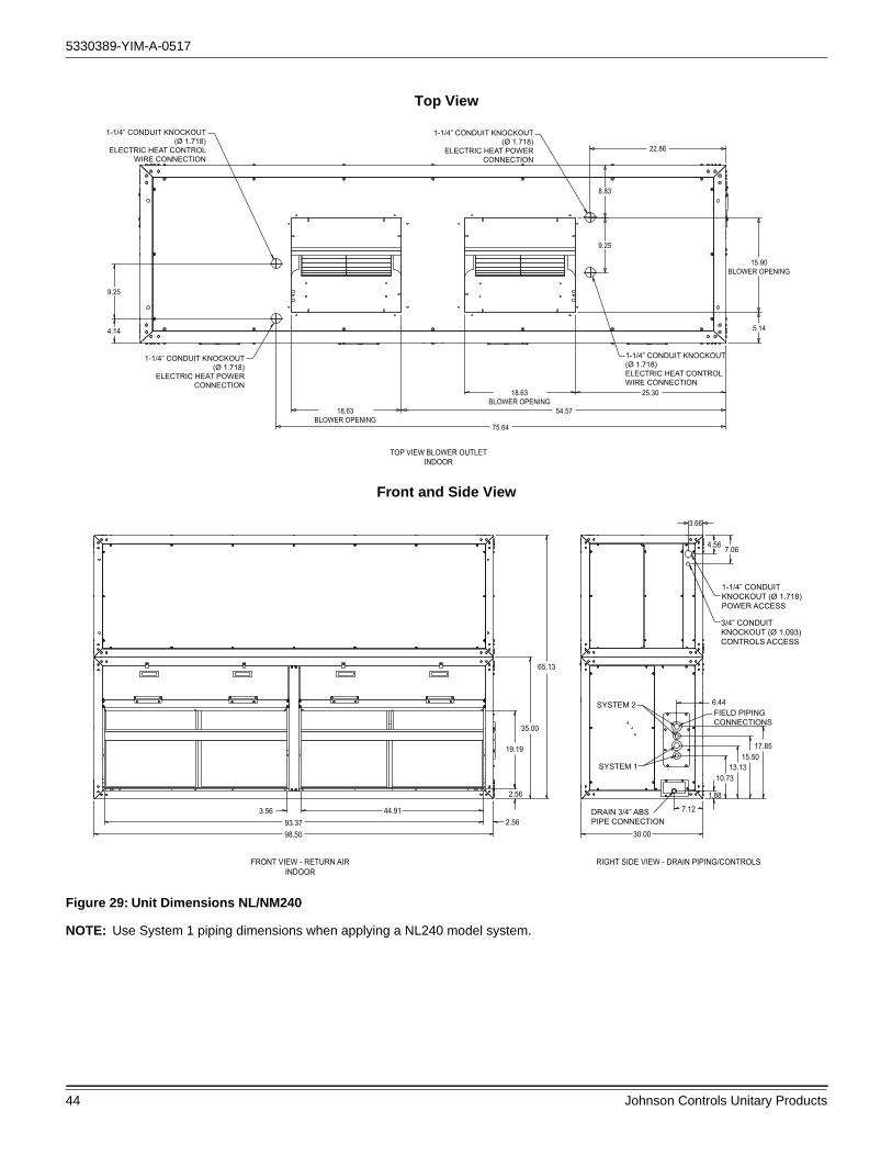
5330389-YIM-A-0517
44 Johnson Controls Unitary Products
Top View
TOP VIEW BLOWER OUTLETINDOOR
1-1/4” CONDUIT KNOCKOUT(Ø 1.718)
ELECTRIC HEAT CONTROLWIRE CONNECTION
4.14
1-1/4” CONDUIT KNOCKOUT(Ø 1.718)
ELECTRIC HEAT POWERCONNECTION
1-1/4” CONDUIT KNOCKOUT(Ø 1.718)ELECTRIC HEAT CONTROLWIRE CONNECTION
1-1/4” CONDUIT KNOCKOUT(Ø 1.718)
ELECTRIC HEAT POWERCONNECTION
9.25
18.63BLOWER OPENING
18.63BLOWER OPENING
15.90BLOWER OPENING
9.25
8.83
22.86
54.57
75.64
25.30
5.14
Front and Side View
FRONT VIEW - RETURN AIRINDOOR
RIGHT SIDE VIEW - DRAIN PIPING/CONTROLS
1-1/4” CONDUITKNOCKOUT (Ø 1.718)POWER ACCESS
3/4” CONDUITKNOCKOUT (Ø 1.093)CONTROLS ACCESS
FIELD PIPINGCONNECTIONS
DRAIN 3/4” ABSPIPE CONNECTION
13.1315.50
17.85
10.73
7.12
1.88
6.44
SYSTEM 1
SYSTEM 2
30.00
3.66
4.56 7.06
65.13
35.00
19.19
2.56
2.56
3.5693.3798.50
44.91
Figure 29: Unit Dimensions NL/NM240
NOTE: Use System 1 piping dimensions when applying a NL240 model system.

5330389-YIM-A-0517
Johnson Controls Unitary Products 45
BOTTOM VIEW
2.72 45.3898.50
50.5945.38 2.72
2.66
11.43
30.00
AIR INAIR IN
Horizontal Configuration
Figure 26: Unit Dimensions NL/NM240 (Continued)
30.00
35.00
60.00
30.00

5330389-YIM-A-0517
46 Johnson Controls Unitary Products
Table 19: Piping, Electrical and Duct Opening Connection Sizes
MODEL NL090 NL120 NM120 NL180 NM180 NL240 NM240
SYSTEM DATA
No. Refrigeration Circuits 1 1 2 1 2 1 2
Suction Line OD (in.) 1 1/8 1 3/8 1 1/8 1 5/8 1 3/8 1 5/8 1 3/8
Liquid Line OD (in.) 5/8 7/8 5/8 7/8 5/8 7/8 7/8
Power Wiring Knockout 1 3/4 1 3/4 1 3/4 1 3/4 1 3/4 1 3/4 1 3/4
Control Wiring Knockout 1 1/8 1 1/8 1 1/8 1 1/8 1 1/8 1 1/8 1 1/8
Electric Heat Wiring Knockout 1 3/4 1 3/4 1 3/4 1 3/4 1 3/4 1 3/4 1 3/4
Drain Line Fitting PVC Stub 3/4 3/4 3/4 3/4 3/4 3/4 3/4
BLOWER OUTLET
Number 1 1 1 1 1 2 2
Width 13.4 15.9 15.9 18.9 18.9 15.9 15.9
Length 15.6 18.6 18.6 21.6 21.6 18.6 18.6
RETURN AIR INLET
Width 20.5 20.5 20.5 27.3 27.3 19.2 19.2
Length 52.0 52.0 52.0 71.9 71.9 93.4 93.4

5330389-YIM-A-0517
Johnson Controls Unitary Products 47
Typical Wiring Diagrams
Air Handling Units
Figure 30: Typical NL090 Wiring Diagram

5330389-YIM-A-0517
48 Johnson Controls Unitary Products
Figure 31: Typical NL120 thru 240, 1.5 Thru 5.0 HP Blower Motor Only Wiring Diagram

5330389-YIM-A-0517
Johnson Controls Unitary Products 49
Figure 32: Typical NL 240, 7.5 HP Blower Motor 208/230 Volt Only Wiring Diagram

5330389-YIM-A-0517
50 Johnson Controls Unitary Products
Figure 33: Typical NL 240, 7.5 HP Blower Motor 460/575 Volt Only Wiring Diagram

5330389-YIM-A-0517
Johnson Controls Unitary Products 51
Figure 34: Typical NM120 thru 240, 1.5 Thru 5.0 HP Blower Motor Only Wiring Diagram
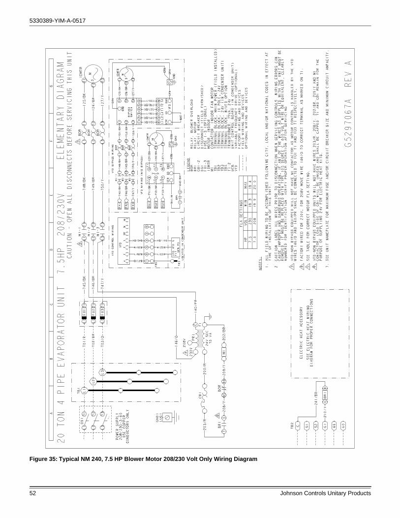
5330389-YIM-A-0517
52 Johnson Controls Unitary Products
Figure 35: Typical NM 240, 7.5 HP Blower Motor 208/230 Volt Only Wiring Diagram

5330389-YIM-A-0517
Johnson Controls Unitary Products 53
Figure 36: Typical NM 240, 7.5 HP Blower Motor 460/575 Volt Only Wiring Diagram

5330389-YIM-A-0517
54 Johnson Controls Unitary Products
Start-Up Sheet
1034350-UCL-D-0817
START-UP & SERVICE DATA INSTRUCTION
START-UP CHECKLISTDate: _______________________________________________________________________________________________________
Job Name: __________________________________________________________________________________________________
Customer Name: _____________________________________________________________________________________________
Address: ____________________________________________________________________________________________________
City: ______________________________ State: ______________________________ Zip: ________________________________
Evaporator Model Number: _______________________________ Serial Number: __________________________________________
Condenser Model Number: _______________________________ Serial Number: __________________________________________
Qualified Start-up Technician: _________________________________ Signature: _________________________________________
HVAC Contractor: _________________________________________________________ Phone: _____________________________
Address: ____________________________________________________________________________________________________
Contractor’s E-mail Address: ____________________________________________________________________________________
Electrical Contractor: _________________________________________________________ Phone:___________________________
Distributor Name: ___________________________________________________________ Phone: ___________________________
WARRANTY STATEMENT
Johnson Controls/UPG is confident that this equipment will operate to the owner's satisfaction if the proper procedures are followed and checks are made at initial start-up. This confidence is supported by the 30 day dealer protection coverage portion of our standard warranty policy which states that Johnson Controls/UPG will cover parts and labor on new equipment start-up failures that are caused by a defect in factory workmanship or material, for a period of 30 days from installation. Refer to current standard warranty policy and warranty manual found on UPGnet for details.
In the event that communication with Johnson Controls/UPG is required regarding technical and/or warranty concerns, all parties to the discussion should have a copy of the equipment start-up sheet for reference. A copy of the original start-up sheet should be filed with the Technical Services Department.
The packaged unit is available in constant or variable air volume versions with a large variety of custom options and accessories available. Therefore, some variation in the startup procedure will exist depending upon the products capacity, control system, options and accessories installed.
This start-up sheet covers all startup check points common to all package equipment. In addition it covers essential startup check points for a number of common installation options. Depending upon the particular unit being started not all sections of this startup sheet will apply. Complete those sections applicable and use the notes section to record any additional information pertinent to your particular installation.
Warranty claims are to be made through the distributor from whom the equipment was purchased.
EQUIPMENT STARTUP
Use the local LCD or Mobile Access Portal (MAP) Gateway to complete the start-up.
A copy of the completed start-up sheet should be kept on file by the distributor providing the equipment and a copy sent to:
Johnson Controls/UPGTechnical Services Department5005 York DriveNorman, OK 73069
COMMERCIAL SPLIT SYSTEMS7.5 To 50.0 TON

5330389-YIM-A-0517
Johnson Controls Unitary Products 55
1034350-UCL-D-0817
2 Unitary Products Group
SAFETY WARNINGS
The inspections and recording of data outlined in this procedure are required for start-up of Johnson Controls/UPG's packaged products. Industry recognized safety standards and practices must be observed at all times. General industry knowledge and experience are required to assure technician safety. It is the responsibility of the technician to assess all potential dangers and take all steps warranted to perform the work in a safe manner. By addressing those potential dangers, prior to beginning any work, the technician can perform the work in a safe manner with minimal risk of injury.
NOTE: Read and review this entire document before beginningany of the startup procedures.
DESIGN APPLICATION INFORMATION
This information will be available from the specifying engineer who selected the equipment. If the system is a VAV system the CFM will be the airflow when the remote VAV boxes are in the
full open position and the frequency drive is operating at 60 HZ. Do not proceed with the equipment start-up without the design CFM information.
Design Supply Air CFM: __________________________ Design Return Air CFM: ______________________________________
Design Outdoor Air CFM At Minimum Pos ition: _______________________________________________________
Tota l Exte rna l S ta tic Pressure : ____________________________________________________________________
Supply S ta tic Pressure : _________________________________________________________________________
Return S ta tic Pressure : _________________________________________________________________________
Des ign Building S ta tic Pressure : __________________________________________________________________
ADDITIONAL APPLICATION NOTES FROM SPECIFYING ENGINEER:
Lethal voltages are present during some start-up checks. Extreme caution must be used at all times.
Moving parts may be exposed during some startup checks. Extreme caution must be used at all times.
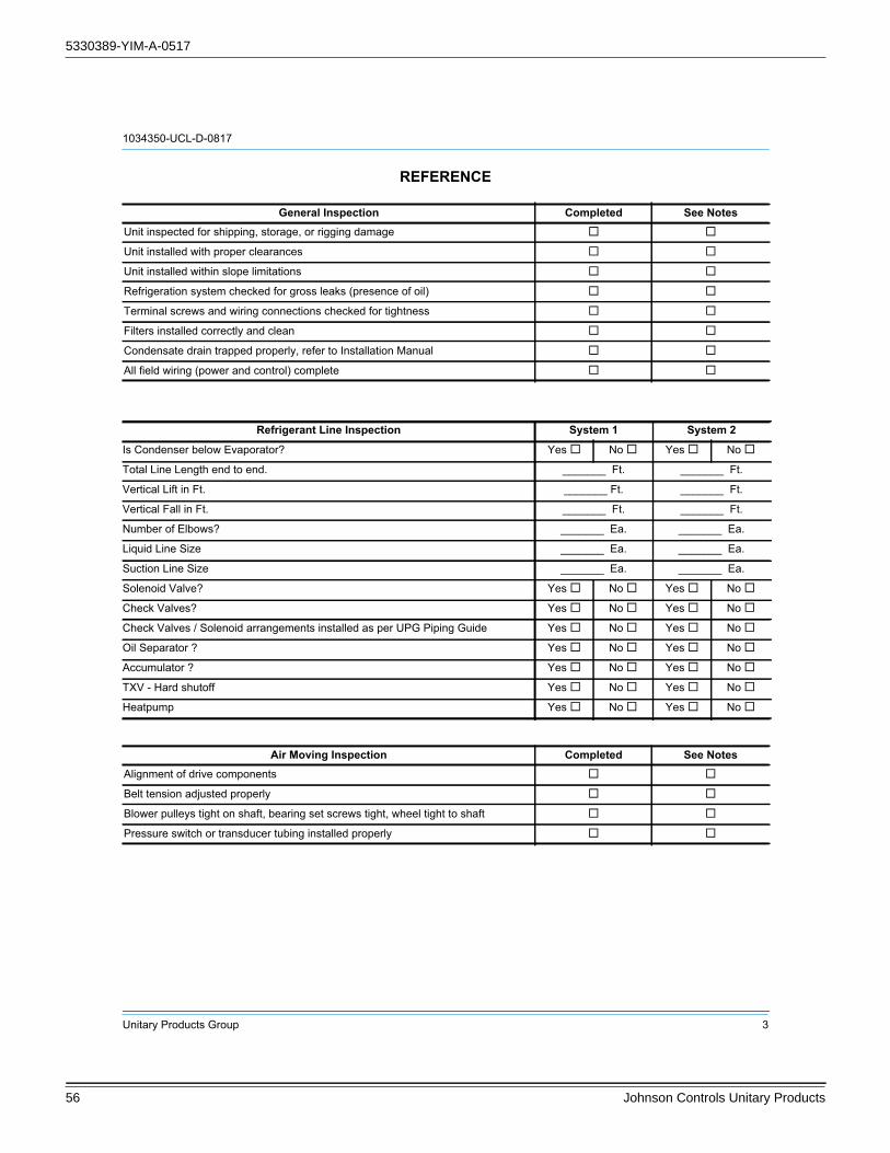
5330389-YIM-A-0517
56 Johnson Controls Unitary Products
1034350-UCL-D-0817
Unitary Products Group 3
REFERENCE
General Inspection Completed See NotesUnit inspected for shipping, storage, or rigging damage
Unit installed with proper clearances
Unit installed within slope limitations
Refrigeration system checked for gross leaks (presence of oil)
Terminal screws and wiring connections checked for tightness
Filters installed correctly and clean
Condensate drain trapped properly, refer to Installation Manual
All field wiring (power and control) complete
Refrigerant Line Inspection System 1 System 2
Is Condenser below Evaporator? Yes No Yes No
Total Line Length end to end. _______ Ft. _______ Ft.
Vertical Lift in Ft. _______ Ft. _______ Ft.
Vertical Fall in Ft. _______ Ft. _______ Ft.
Number of Elbows? _______ Ea. _______ Ea.
Liquid Line Size _______ Ea. _______ Ea.
Suction Line Size _______ Ea. _______ Ea.
Solenoid Valve? Yes No Yes No
Check Valves? Yes No Yes No
Check Valves / Solenoid arrangements installed as per UPG Piping Guide Yes No Yes No
Oil Separator ? Yes No Yes No
Accumulator ? Yes No Yes No
TXV - Hard shutoff Yes No Yes No
Heatpump Yes No Yes No
Air Moving Inspection Completed See NotesAlignment of drive components
Belt tension adjusted properly
Blower pulleys tight on shaft, bearing set screws tight, wheel tight to shaft
Pressure switch or transducer tubing installed properly

5330389-YIM-A-0517
Johnson Controls Unitary Products 57
1034350-UCL-D-0817
4 Unitary Products Group
Operating Measurements - Air Flow
ELECTRICAL DATAT1 - T2 ____________________________ Volts
Control Voltage ______________________ Volts
T2 - T3 ____________________________ Volts
T1 - T3 ____________________________ Volts
Fan operates with proper rotation (All VFD equipped units with the optional Manual Bypass must be phased for correct blower rotation with the Bypass switch set in the LINE position) ID Fans Exh. Fans Cond. Fans
Pressure drop across dry evaporator coil (At maximum design CFM) 1
1. Consult the proper airflow to pressure drop table to obtain the actual airflow at the measured pressure differential.
IWC
External Static Pressure IWC
Return Static Pressure IWC
Supply Static Pressure IWC
Supply Air CFM Using Dry Coil Chart CFM
Final Adjusted Supply Air CFM2
2. Was a motor pulley adjustment or change required to obtain the correct airflow?Was it necessary to increase of decrease the airflow to meet the design conditions?If the motor pulley size was changed, measure the outside diameters of the motor and blower pulleys and record those diameters here;
Blower Motor HP _______________________________FLA________ RPM________
Pulley Pitch Diameter ______________Turns Out________ Final Turns Out________
Blower Pulley Pitch Diameter ________________ Fixed Sheave_________________
CFM
Device Nameplate Measured List All Three Amperages
Supply Fan Motor1,2
1. VAV units with heat section - simulate heat call to drive VAV boxes and VFD/IGV to maximum design airflow position.2. VAV units without hea t section - VAV boxes mus t be se t to maximum des ign a irflow pos ition. Notes above apply for 3rd party application only.
AMPS AMPS
Condenser Fan #1 AMPS AMPS
Condenser Fan #2 (if equipped) AMPS AMPS
Condenser Fan #3 (if equipped) AMPS AMPS
Condenser Fan #4 (if equipped) AMPS AMPS
Compressor #1 AMPS AMPS
Compressor #2 (if equipped) AMPS AMPS
Compressor #3 (if equipped) AMPS AMPS
Compressor #4 (if equipped) AMPS AMPS

5330389-YIM-A-0517
58 Johnson Controls Unitary Products
1034350-UCL-D-0817
Unitary Products Group 5
OPERATING MEASUREMENTS - COOLING
REFRIGERANT SAFETIES
OPERATING MEASUREMENTS ELECTRIC HEATING
Heater kW ____________kW Heater Voltage, Nameplate ____________ Volts
Heater Model Number: _______________________________
Serial Number: ______________________________________
Stage Discharge Pressure
Discharge Temp.
Liquid LinePressure At
Service Valve
Liquid Line Temp.1
1. Liquid line temperature should be taken before filter/drier.
Subcooling2
2. Subtract 10 psi from discharge pressure for estimated liquid line pressure
Suction Pressure
Suction Temp. Superheat
First3
3. If Rawal valve installed, contact Technical Service.
# ° # ° ° # ° °Second (if equipped) # ° # ° ° # ° °Third (if equipped) # ° # ° ° # ° °Fourth (if equipped) # ° # ° ° # ° °Heat Pump 1st Stage # ° # ° ° # ° °
Outside air temperature ________________ db °F ________________ wb °F ________________ RH%
Return Air Temperature ________________ db °F ________________ wb °F ________________ RH%
Mixed Air Temperature ________________ db °F ________________ wb °F ________________ RH%
Supply Air Temperature ________________ db °F ________________ wb °F ________________ RH%
Action Completed See NotesProve Compressor Rotation (3 phase only) by guage pressure
Prove High Pressure Safety, All Systems
Prove Low Pressure Safety, All Systems
Heater Nameplate Measured List All Three Amperages
Stage 1 _________AMPS _________AMPS _________AMPS _________AMPS
Stage 2 _________AMPS _________AMPS _________AMPS _________AMPS
Stage 3 _________AMPS _________AMPS _________AMPS _________AMPS
Stage 4 _________AMPS _________AMPS _________AMPS _________AMPS
Checked Heater Limit Yes No
Air Moving Switch Installed? Yes No

Subject to change without notice. Printed in U.S.A. 5330389-YIM-A-0517Copyright © 2017 by Johnson Controls, Inc. All rights reserved. Supersedes: Nothing
York International Corporation5005 York Drive
Norman, OK 73069
OPERATIONAL MEASUREMENTS - STAGING CONTROLS
FINAL - INSPECTION
OBSERVED PRODUCT DEFICIENCIES & CONCERNS:
________________________________________________________________________________________________________
________________________________________________________________________________________________________
________________________________________________________________________________________________________
________________________________________________________________________________________________________
________________________________________________________________________________________________________
________________________________________________________________________________________________________
________________________________________________________________________________________________________
________________________________________________________________________________________________________
________________________________________________________________________________________________________
________________________________________________________________________________________________________
________________________________________________________________________________________________________
________________________________________________________________________________________________________
________________________________________________________________________________________________________
________________________________________________________________________________________________________
________________________________________________________________________________________________________
Verify Proper Operation of Heating/Cooling Staging ControlsCreate a cooling demand at the Thermostat, BAS System or Smart Equipment™Verify that cooling/economizer stages are energized.
Create a heating demand at the Thermostat, BAS System or Smart Equipment™Verify that heating stages are energized.
Verify Proper Operation of the Variable Frequency Drive (If Required)Verify that motor speed modulates with duct pressure change.
Verify that all operational control set points have been set to desired valueScroll through all setpoints and change as may be necessary to suit the occupant requirements.
Verify that all option parameters are correctScroll through all option parameters and ensure that all installed options are enabled in the software and all others are disabled in the software. (Factory software settings should match the installed options)
Verify that all access panels have been closed and secured
Save a backup file from the unit control board onto a USB flash drive.
Related Documents