R-410A 1062414-YIM-B-0517 MODELS: NC300, 2-Pipe ND360 - 600, 4-Pipe 25 - 50 Ton, 60 Hertz TABLE OF CONTENTS General . . . . . . . . . . . . . . . . . . . . . . . . . . . . . . . . . . . . . . . . . . 2 Safety Considerations . . . . . . . . . . . . . . . . . . . . . . . . . . . . . . . 2 Reference . . . . . . . . . . . . . . . . . . . . . . . . . . . . . . . . . . . . . . 2 Agency Approvals . . . . . . . . . . . . . . . . . . . . . . . . . . . . . . . . . . 2 Inspection . . . . . . . . . . . . . . . . . . . . . . . . . . . . . . . . . . . . . . . . 2 Nomenclature . . . . . . . . . . . . . . . . . . . . . . . . . . . . . . . . . . . . . 3 Unit Application Data. . . . . . . . . . . . . . . . . . . . . . . . . . . . . . 3 Physical Data Indoor Unit . . . . . . . . . . . . . . . . . . . . . . . . . . 4 Unit Installation . . . . . . . . . . . . . . . . . . . . . . . . . . . . . . . . . . . . 5 Location. . . . . . . . . . . . . . . . . . . . . . . . . . . . . . . . . . . . . . . . 5 Rigging . . . . . . . . . . . . . . . . . . . . . . . . . . . . . . . . . . . . . . . . 5 Clearances . . . . . . . . . . . . . . . . . . . . . . . . . . . . . . . . . . . . . 5 Air Discharge Conversion . . . . . . . . . . . . . . . . . . . . . . . . . . 5 Unit Mounting . . . . . . . . . . . . . . . . . . . . . . . . . . . . . . . . . . . 8 Refrigerant Mains . . . . . . . . . . . . . . . . . . . . . . . . . . . . . . . 12 Expansion Valve Bulb Installation . . . . . . . . . . . . . . . . . . . 14 Duct Connections . . . . . . . . . . . . . . . . . . . . . . . . . . . . . . . 14 Electrical Data . . . . . . . . . . . . . . . . . . . . . . . . . . . . . . . . . . . . 16 Electrical Connections Air Handlers with Contactor . . . . . 17 ND600 Bearing Alignment: . . . . . . . . . . . . . . . . . . . . . . . . 19 Air System Adjustment . . . . . . . . . . . . . . . . . . . . . . . . . . . 21 Twin Belt Drive Adjustment . . . . . . . . . . . . . . . . . . . . . . . . 21 Airflow Performance . . . . . . . . . . . . . . . . . . . . . . . . . . . . . . . 22 Maintenance . . . . . . . . . . . . . . . . . . . . . . . . . . . . . . . . . . . . . 35 Typical Wiring Diagrams . . . . . . . . . . . . . . . . . . . . . . . . . . . . 36 Start-Up Sheet . . . . . . . . . . . . . . . . . . . . . . . . . . . . . . . . . . . 41 LIST OF TABLES 1 Unit Application Data . . . . . . . . . . . . . . . . . . . . . . . . . . . . 3 2 Physical Data Indoor Unit . . . . . . . . . . . . . . . . . . . . . . . . 4 3 Unit Mounting Dimensions . . . . . . . . . . . . . . . . . . . . . . . 11 4 Corner Weights & Center of Gravity NC/ND Units . . . . . 11 5 Accessory Operating Weight Distribution (Lbs) . . . . . . . 12 6 Electrical Data . . . . . . . . . . . . . . . . . . . . . . . . . . . . . . . . 16 7 Overload Relay Kit . . . . . . . . . . . . . . . . . . . . . . . . . . . . . 17 8 Overload Setting . . . . . . . . . . . . . . . . . . . . . . . . . . . . . . 17 9 Standard (Non VFD) & Intellispeed (ISP) Low Voltage Wiring . . . . . . . . . . . . . . . . . . . . . . . . . . . . . . . . . . . . . . . 17 10 Unit Blower Motor Data . . . . . . . . . . . . . . . . . . . . . . . . . 18 11 Unit Drive Data . . . . . . . . . . . . . . . . . . . . . . . . . . . . . . . . 21 12 Fan Performance Data - 25 Ton . . . . . . . . . . . . . . . . . . 22 13 Fan Performance Data - 30 Ton . . . . . . . . . . . . . . . . . . 22 14 Fan Performance Data - 40 Ton . . . . . . . . . . . . . . . . . . 22 15 Fan Performance Data - 50 Ton . . . . . . . . . . . . . . . . . . 23 16 Unit Connection Sizes . . . . . . . . . . . . . . . . . . . . . . . . . . 35 LIST OF FIGURES 1 NC300 and ND360/480 Vertical Airflow Arrangements . . 6 2 NC300 and ND360/480 Horizontal Airflow Arrangements 6 3 ND600 & M1CZ600 Airflow Arrangements . . . . . . . . . . . 7 4 NC300/ND480/ND360 Weight Distribution With Suspension Application . . . . . . . . . . . . . . . . . . . . . . . . . . 8 5 NC300/ND360/ND480 Details For Securing Suspension Channels . . . . . . . . . . . . . . . . . . . . . . . . . . . . . . . . . . . . . 9 6 ND600 & M1CZ600 Weight Distribution With Suspension Application . . . . . . . . . . . . . . . . . . . . . . . . . . . . . . . . . . . . 9 7 ND600 & M1CZ600 Details For Securing Suspension Channels . . . . . . . . . . . . . . . . . . . . . . . . . . . . . . . . . . . . 10 8 Recommended Drain Piping . . . . . . . . . . . . . . . . . . . . . 12 9 Suggested Method For Connecting Ductwork . . . . . . . . 15 10 NC300/ND360/ND480 Motor Arrangements As Seen In Figures 1 and 2 . . . . . . . . . . . . . . . . . . . . . . . . . . . . . . . 19 11 ND600 Factory Motor Mounting Position . . . . . . . . . . . . 20 12 ND600 Center Bearing . . . . . . . . . . . . . . . . . . . . . . . . . . 20 13 ND600 Motor Mount Plate . . . . . . . . . . . . . . . . . . . . . . . 20 14 Double Groove Pulley . . . . . . . . . . . . . . . . . . . . . . . . . . 21 15 Hole Locations For Reading Coil Pressure Drop . . . . . . 23 16 NC300 - Pressure Drop Vs. Cfm Across Dry Indoor Coil 24 17 ND360 - Pressure Drop Vs. Cfm Across Dry Indoor Coil 24 18 ND600 & M1CZ600 - Pressure Drop Vs. Cfm Across Dry Indoor Coil . . . . . . . . . . . . . . . . . . . . . . . . . . . . . . . . . . . 25 19 ND480 - Pressure Drop Vs. Cfm Across Dry Indoor Coil 25 20 NC300 Unit Dimensions . . . . . . . . . . . . . . . . . . . . . . . . . 26 21 NC300 Unit Dimensions (Continued) . . . . . . . . . . . . . . . 27 22 ND360 Unit Dimensions . . . . . . . . . . . . . . . . . . . . . . . . . 28 23 ND360 Unit Dimensions (Continued) . . . . . . . . . . . . . . . 29 24 ND480 Unit Dimensions . . . . . . . . . . . . . . . . . . . . . . . . . 30 25 ND480 Unit Dimensions (Continued) . . . . . . . . . . . . . . . 31 26 ND600 Unit Dimensions . . . . . . . . . . . . . . . . . . . . . . . . . 32 27 M1CZ600 Evaporator Section Dimensions . . . . . . . . . . 33 28 ND600 Air Handler & M1CZ600 Evaporator Coil Dimensions . . . . . . . . . . . . . . . . . . . . . . . . . . . . . . . . . . 34 29 Typical NC300 Indoor Unit Wiring Diagram . . . . . . . . . . 36 30 Typical ND360, 480 & 600 Indoor Unit Wiring Diagram (Contactor) . . . . . . . . . . . . . . . . . . . . . . . . . . . . . . . . . . . 37 31 Typical Field Wiring Diagram - NC300 Evaporator Unit with YC300 Condenser Unit . . . . . . . . . . . . . . . . . . . . . . . . . 38 32 Typical NC300 Liquid Line Solenoid Wiring . . . . . . . . . . 38 33 Typical Field Wiring Diagram ND360/480 Evaporator Units, ND600 Air Handler and M1CZ600A Evaporator Coil when Matched with YD360/480/600 Condenser . . . . . . . . . . . 39 34 Typical ND360/480 & M1CZ600A Liquid Line Solenoid 39 35 Typical Liquid Line Solenoid Wiring . . . . . . . . . . . . . . . . 40

Welcome message from author
This document is posted to help you gain knowledge. Please leave a comment to let me know what you think about it! Share it to your friends and learn new things together.
Transcript

R-410A
1062414-YIM-B-0517
MODELS: NC300, 2-PipeND360 - 600, 4-Pipe
25 - 50 Ton, 60 Hertz
TABLE OF CONTENTSGeneral . . . . . . . . . . . . . . . . . . . . . . . . . . . . . . . . . . . . . . . . . . 2Safety Considerations . . . . . . . . . . . . . . . . . . . . . . . . . . . . . . . 2
Reference . . . . . . . . . . . . . . . . . . . . . . . . . . . . . . . . . . . . . . 2Agency Approvals . . . . . . . . . . . . . . . . . . . . . . . . . . . . . . . . . . 2Inspection . . . . . . . . . . . . . . . . . . . . . . . . . . . . . . . . . . . . . . . . 2Nomenclature . . . . . . . . . . . . . . . . . . . . . . . . . . . . . . . . . . . . . 3
Unit Application Data. . . . . . . . . . . . . . . . . . . . . . . . . . . . . . 3Physical Data Indoor Unit . . . . . . . . . . . . . . . . . . . . . . . . . . 4
Unit Installation . . . . . . . . . . . . . . . . . . . . . . . . . . . . . . . . . . . . 5Location. . . . . . . . . . . . . . . . . . . . . . . . . . . . . . . . . . . . . . . . 5Rigging . . . . . . . . . . . . . . . . . . . . . . . . . . . . . . . . . . . . . . . . 5Clearances . . . . . . . . . . . . . . . . . . . . . . . . . . . . . . . . . . . . . 5Air Discharge Conversion . . . . . . . . . . . . . . . . . . . . . . . . . . 5
Unit Mounting . . . . . . . . . . . . . . . . . . . . . . . . . . . . . . . . . . . 8Refrigerant Mains . . . . . . . . . . . . . . . . . . . . . . . . . . . . . . . 12Expansion Valve Bulb Installation . . . . . . . . . . . . . . . . . . . 14Duct Connections . . . . . . . . . . . . . . . . . . . . . . . . . . . . . . . 14
Electrical Data . . . . . . . . . . . . . . . . . . . . . . . . . . . . . . . . . . . . 16Electrical Connections Air Handlers with Contactor . . . . . 17ND600 Bearing Alignment: . . . . . . . . . . . . . . . . . . . . . . . . 19Air System Adjustment . . . . . . . . . . . . . . . . . . . . . . . . . . . 21Twin Belt Drive Adjustment . . . . . . . . . . . . . . . . . . . . . . . . 21
Airflow Performance . . . . . . . . . . . . . . . . . . . . . . . . . . . . . . . 22Maintenance . . . . . . . . . . . . . . . . . . . . . . . . . . . . . . . . . . . . . 35Typical Wiring Diagrams . . . . . . . . . . . . . . . . . . . . . . . . . . . . 36Start-Up Sheet . . . . . . . . . . . . . . . . . . . . . . . . . . . . . . . . . . . 41
LIST OF TABLES1 Unit Application Data . . . . . . . . . . . . . . . . . . . . . . . . . . . . 32 Physical Data Indoor Unit . . . . . . . . . . . . . . . . . . . . . . . . 43 Unit Mounting Dimensions . . . . . . . . . . . . . . . . . . . . . . . 114 Corner Weights & Center of Gravity NC/ND Units . . . . . 115 Accessory Operating Weight Distribution (Lbs) . . . . . . . 126 Electrical Data . . . . . . . . . . . . . . . . . . . . . . . . . . . . . . . . 167 Overload Relay Kit . . . . . . . . . . . . . . . . . . . . . . . . . . . . . 178 Overload Setting . . . . . . . . . . . . . . . . . . . . . . . . . . . . . . 17
9 Standard (Non VFD) & Intellispeed (ISP) Low Voltage Wiring . . . . . . . . . . . . . . . . . . . . . . . . . . . . . . . . . . . . . . . 17
10 Unit Blower Motor Data . . . . . . . . . . . . . . . . . . . . . . . . . 1811 Unit Drive Data . . . . . . . . . . . . . . . . . . . . . . . . . . . . . . . . 2112 Fan Performance Data - 25 Ton . . . . . . . . . . . . . . . . . . 2213 Fan Performance Data - 30 Ton . . . . . . . . . . . . . . . . . . 2214 Fan Performance Data - 40 Ton . . . . . . . . . . . . . . . . . . 2215 Fan Performance Data - 50 Ton . . . . . . . . . . . . . . . . . . 2316 Unit Connection Sizes . . . . . . . . . . . . . . . . . . . . . . . . . . 35
LIST OF FIGURES1 NC300 and ND360/480 Vertical Airflow Arrangements . . 62 NC300 and ND360/480 Horizontal Airflow Arrangements 63 ND600 & M1CZ600 Airflow Arrangements . . . . . . . . . . . 74 NC300/ND480/ND360 Weight Distribution With
Suspension Application . . . . . . . . . . . . . . . . . . . . . . . . . . 85 NC300/ND360/ND480 Details For Securing Suspension
Channels . . . . . . . . . . . . . . . . . . . . . . . . . . . . . . . . . . . . . 96 ND600 & M1CZ600 Weight Distribution With Suspension
Application . . . . . . . . . . . . . . . . . . . . . . . . . . . . . . . . . . . . 97 ND600 & M1CZ600 Details For Securing Suspension
Channels . . . . . . . . . . . . . . . . . . . . . . . . . . . . . . . . . . . . 108 Recommended Drain Piping . . . . . . . . . . . . . . . . . . . . . 129 Suggested Method For Connecting Ductwork . . . . . . . . 15
10 NC300/ND360/ND480 Motor Arrangements As Seen In Figures 1 and 2 . . . . . . . . . . . . . . . . . . . . . . . . . . . . . . . 19
11 ND600 Factory Motor Mounting Position . . . . . . . . . . . . 2012 ND600 Center Bearing . . . . . . . . . . . . . . . . . . . . . . . . . . 2013 ND600 Motor Mount Plate . . . . . . . . . . . . . . . . . . . . . . . 2014 Double Groove Pulley . . . . . . . . . . . . . . . . . . . . . . . . . . 2115 Hole Locations For Reading Coil Pressure Drop . . . . . . 2316 NC300 - Pressure Drop Vs. Cfm Across Dry Indoor Coil 2417 ND360 - Pressure Drop Vs. Cfm Across Dry Indoor Coil 2418 ND600 & M1CZ600 - Pressure Drop Vs. Cfm Across Dry
Indoor Coil . . . . . . . . . . . . . . . . . . . . . . . . . . . . . . . . . . . 25
19 ND480 - Pressure Drop Vs. Cfm Across Dry Indoor Coil 2520 NC300 Unit Dimensions . . . . . . . . . . . . . . . . . . . . . . . . . 2621 NC300 Unit Dimensions (Continued) . . . . . . . . . . . . . . . 2722 ND360 Unit Dimensions . . . . . . . . . . . . . . . . . . . . . . . . . 2823 ND360 Unit Dimensions (Continued) . . . . . . . . . . . . . . . 2924 ND480 Unit Dimensions . . . . . . . . . . . . . . . . . . . . . . . . . 3025 ND480 Unit Dimensions (Continued) . . . . . . . . . . . . . . . 3126 ND600 Unit Dimensions . . . . . . . . . . . . . . . . . . . . . . . . . 3227 M1CZ600 Evaporator Section Dimensions . . . . . . . . . . 3328 ND600 Air Handler & M1CZ600 Evaporator Coil
Dimensions . . . . . . . . . . . . . . . . . . . . . . . . . . . . . . . . . . 3429 Typical NC300 Indoor Unit Wiring Diagram . . . . . . . . . . 3630 Typical ND360, 480 & 600 Indoor Unit Wiring Diagram
(Contactor) . . . . . . . . . . . . . . . . . . . . . . . . . . . . . . . . . . . 3731 Typical Field Wiring Diagram - NC300 Evaporator Unit with
YC300 Condenser Unit . . . . . . . . . . . . . . . . . . . . . . . . . 3832 Typical NC300 Liquid Line Solenoid Wiring . . . . . . . . . . 3833 Typical Field Wiring Diagram ND360/480 Evaporator Units,
ND600 Air Handler and M1CZ600A Evaporator Coil when Matched with YD360/480/600 Condenser . . . . . . . . . . . 39
34 Typical ND360/480 & M1CZ600A Liquid Line Solenoid 3935 Typical Liquid Line Solenoid Wiring . . . . . . . . . . . . . . . . 40

1062414-YIM-B-0517
2 Johnson Controls Unitary Products
General
The NC/ND Series evaporator units are designed to match with YC/YD Series condensing units. When matched, these units meet ASHRE 90.1 standards.
NC300, ND360 and ND480 units consist of an evaporator coil section and a blower section that are factory assembled and shipped as shown in Figures 20 thru 25. These sections may be rearranged in the field for other air discharge patterns as shown in Figures 1 and 2.
ND600 units consist of a blower section only and must be matched with an M1CZ600 evaporator coil as shown in Figures 27 thru 28. These units are shipped separately and must be field assembled as shown in Figure 28. These sections may be rearranged for other air discharge patterns as shown in Figure 3.
The NC/ND evaporator coils have 24 volt normally closed solenoid valves, that when matched with the YC/YD condensing units Smart Equipment™ controls provide capacity staging and pump out for higher efficiencies and product reliability.
The NC300 product can be field equipped with the IntelliSpeed discrete fan control (Multi-Speed) VFD option. Please refer to price pages, VFD kit installation instructions for additional details
Safety Considerations
Installer should pay particular attention to the words: NOTE, CAUTION, and WARNING. Notes are intended to clarify or make the installation easier. Cautions are given to prevent equipment damage. Warnings are given to alert installer that personal injury and/or equipment damage may result if installation procedure is not handled properly.
Reference
This instruction covers the installation and operation of evaporator blower units. For information on the operation of matching condensing units, refer to Installation Manual - 1062414 for cooling units.
Additional information on the design, installation, operation and service of this equipment is available in the following Technical Guides Model No. YC300/NC300 Technical Guide-505428, Model No.YD360 thru 600 Technical Guide-628770 and Model No. ND360 thru 600 Technical Guide-628767.
Renewal Parts
Contact your local Source 1 parts distribution center for authorized replacement parts.
Agency Approvals
Design certified by CSA as follows:
1. For use as a cooling coil.
2. For indoor installation only.
Inspection
As soon as a unit is received, it should be inspected for possible damage during transit. If damage is evident, the extent of the damage should be noted on the carrier’s freight bill. A separate request for inspection by the carrier’s agent should be made in writing.Improper installation may create a condition where the
operation of the product could cause personal injury or property damage.
Improper installation, adjustment, alteration, service or maintenance can cause injury or property damage. Refer to this manual for assistance or for additional information, consult a qualified contractor, installer or service agency.
This system uses R-410A Refrigerant which operates at higher pressures than R-22. No other refrigerant may be used in this system. Gage sets, hoses, refrigerant containers and recovery systems must be designed to handle R-410A. If you are unsure, consult the equipment manufacturer. Failure to use R-410A compatible servicing equipment may result in property damage or injury.
This product must be installed in strict compliance with the enclosed installation instructions and any applicable local, state and national codes including, but not limited to, building, electrical, and mechanical codes.
Wear safety glasses and gloves when handling refrigerants. Failure to follow this warning can cause serious personal injury.

1062414-YIM-B-0517
Johnson Controls Unitary Products 3
Nomenclature
Unit Application Data
Table 1: Unit Application Data
Model Power Supply VoltageVoltage Variation Supply Air Range CFM
Entering Air Temperature Degrees °FCoolingDB/WB
Heating DB1
1. Heating Min/Max temperatures apply to steam and hot water coils. NOTE: Do not apply steam to hot water coils.
Min. Max. Min. Max. Min. Max. Min. Max.
NC300208/230-3-60 187 253 8,000 12,000 65/57 95/72 40 77
460-3-60 414 506 8,000 12,000 65/57 95/72 40 77575-3-60 540 630 8,000 12,000 65/57 95/72 40 77
ND360208/230-3-60 187 253 10,000 14,000 65/57 95/72 40 77
460-3-60 414 506 10,000 14,000 65/57 95/72 40 77575-3-60 540 630 10,000 14,000 65/57 95/72 40 77
ND480208/230-3-60 187 253 12,800 19,200 65/57 95/72 40 77
460-3-60 414 506 12,800 19,200 65/57 95/72 40 77575-3-60 540 630 12,800 19,200 65/57 95/72 40 77
ND600208/230-3-60 187 253 16,000 24,000 65/57 95/72 40 77
460-3-60 414 506 16,000 24,000 65/57 95/72 40 77575-3-60 540 630 16,000 24,000 65/57 95/72 40 77
Product CategoryN = Split System, Air Handler, AC R-410A
Product IdentifierC = Standard Efficiency, 2-Pipe (25T)D = Standard Efficiency, 4-Pipe (30-50T)
Nominal Cooling Capacity - MBH300 = 25 Ton1
360 = 30 Ton480 = 40 Ton600 = 50 Ton
C00 = Cooling Only
5 = 575-3-606 = 208/230/460-3-60
Configured Split Air Handler Model Number Nomenclature
Product Generation1 = First Generation
Voltage
Heat Type & Nominal Heat Capacity
N C 300 C00 N 6 A AA 1 AProduct Style
A = Style A
Installation OptionsA = None
Product Options1
AA = No Options InstalledEJ = ElectroFin Evap Coil (25 Ton Only)TJ = Technicoat Evap Coil (See Note 1.)
1. ND600C00ANAAA1 airhandler does not include evaporator coil. Customer must order M1CZ600A Standard Coil or M1CZ600T Technicoat Coil.
2. Motors, drives, overloads are not shipped with 25-50 ton AH units.
N = None (Motor, Motor Dr. & Motor Overload Kits Req.)Airflow2
1. ND300 Not Offered.

1062414-YIM-B-0517
4 Johnson Controls Unitary Products
Physical Data Indoor Unit
Table 2: Physical Data Indoor Unit
ComponentModels
NC3001 2 ND360 ND480 ND6003
Nominal Tonnage 25 30 40 50
DIMENSIONS (inches)
Length 100.1 100.1 103.1 105.1
Width 38.1 38.1 45.4 53.7
Height 74.6 74.6 89.4 99.0
WEIGHTS4 (lb)
Unit Shipping 1067 1122 1246 1684
Unit Operating With5 hp Motor and Drive 1130 1184 --- ---
7.5 hp Motor and Drive 1157 1208 1348 ---
10 hp Motor and Drive --- 1224 1364 1742
15 hp Motor and Drive --- --- --- 1859
INDOOR BLOWER
Diameter x Width 18 X 18 18 X 18 18 X 18 20 x 18
Qty. 2 2 2 2
INDOOR COIL
Face area (Sq. Ft.) 25.8 25.8 33.3 41.3
Rows 4 4 4 4
Fins per inch 16 16 16 16
Tube diameter 3/8 3/8 3/8 3/8
Circuitry Type Interlaced Interlaced Interlaced Interlaced
Refrigerant Control TEV TEV TEV TEV
SYSTEM DATA
No. Refrigeration Circuits 1 2 2 2
Suction Line OD (in.) 2 1/8 1 1/8 1 3/8 2 1/8
Liquid Line OD (in.) 7/8 7/8 7/8 7/8
FILTERS
Size and Quantity Per Model (In.)
16 x 20 x 2 --- --- 6 ---
20 x 20 x 2 --- --- 3 ---
20 x 22 x 2 --- --- --- ---
16 x 25 x 2 --- --- --- 6
20 x 25 x 2 10 10 6 3
25 x 25 x 2 --- --- --- 6
Face area (Sq. Ft.) 34.7 34.7 42.6 53.1
ACCESSORY
HOT WATER COIL DATA
Face area (Sq. Ft.) 21.2 21.2 27.2 27.2
Rows 2 2 2 2
Fins per inch 12 12 12 8
Tube diameter (Copper) OD (In.) 1/2 1/2 1/2 1/2
Connections (Supply and Return) OD (In.) 1 3/8 1 3/8 1 5/8 1 5/8
Weight (lb) 150 150 190 190
STEAM COIL DATA
Face area (Sq. Ft.) 18.2 18.2 --- ---
Rows 1 1 --- ---
Fins per inch 8 8 --- ---
Tube diameter (Copper) (In.) 1 1 --- ---
Connection, (NPTE) (In.)Inlet 2 2 --- ---
Outlet 1-1/2 1-1/2 --- ---
Weight (lb) 160 160 --- ---
1. Motors, Drive and Overload Kits must be ordered separately for the NC300. The Motor Drive and Overload Kits are to be field installed.
2. IntelliSpeed discrete fan control option for NC300 is field installed only. Please refer to price pages or UST to select proper motor, drive, and IntelliSpeed VFD kit.
3. ND600 and M1CZ600A Combined4. Motor, Motor Drive and Motor Overload Kits must be ordered separately, The Motor,
Motor Drive and Overload Kits are to be field installed.

1062414-YIM-B-0517
Johnson Controls Unitary Products 5
Unit Installation
Location
The evaporator blowers are not designed for outdoor installation. They must be located inside the building structure, either inside or outside the conditioned space where they are protected from rain and other such moisture.
The unit should be located as close to the condensing unit as practical and positioned to minimize bends in the refrigerant piping.
Units being installed vertically or horizontally can be set directly on a floor or platform, or supported by metal or wooden beams.
Units being installed horizontally can be suspended from above as shown in Figures 5 and 6.
Rigging
Care must be taken when moving the unit. Do not remove any packaging until the unit is near the place of installation. SPREADER BARS SHOULD BE USED BETWEEN THE SLINGS TO PREVENT CRUSHING THE UNIT FRAME OR PANELS. When preparing to move the unit, always determine the center of gravity of the unit in order to equally distribute the weight. Rig the unit by attaching chain or cable slings around the bottom skid. A lift truck may be used to raise a unit to a suspended location. Refer to Table 2 for the total unit operating weight.
Clearances
A 25-inch clearance is required on the end with the piping connections and the supply air blower motor to properly service and maintain the unit and to replace the filters.
Some clearance will also be required for the duct and power wire connections. A clearance equal to the unit width is required
on one end of the unit if the blower shaft or evaporator coil is to be replaced without moving the unit.
Air Discharge Conversion
NC300/ND360/ND480 Air Discharge
These units are shipped for upflow operation, but may be converted for any of the illustrated air discharge patterns shown in Figures 1 and 2.
Convert as follows:
1. Remove the (blower section) panels.
2. Remove the Phillips machine screws located inside casing corner angles that hold the evaporator and blower sections together.
3. Rotate the blower section for the desired air discharge orientation.
NOTE: Before proceeding to step 4, see the section on the blower motor mounting locations and mount the blower motor in the desired position.
4. If accessory heating coils are used, mount heating coil between evaporator and blower sections. Screw fastening locations are the same for all sections and heating accessories. If heating coils are not used, fasten evaporator section to blower section with machine screws removed in step 2.
5. See duct and drain connections.
6. Replace panels.

1062414-YIM-B-0517
6 Johnson Controls Unitary Products
Figure 1: NC300 and ND360/480 Vertical Airflow Arrangements
NOTE: *If required, some air can be returned through the bottom of the evaporator section
Figure 2: NC300 and ND360/480 Horizontal Airflow Arrangements
AIRA
IR BLOWER
1
EVAPORATORCOIL
AIR
AIR
2
AIR
AIR
AIR
4
AIR
AIR
5
AIR
AIR
6
3
AIR
AIR
AIR
AIR
AIR
AIR
AIR
AIR
AIR
AIR
AIR
AIR
7 8 9
11 1210

1062414-YIM-B-0517
Johnson Controls Unitary Products 7
ND600 Air Discharge
The ND600 blower and M1CZ600 evaporator sections are shipped separately and must be joined together in the field. The blower section can be mounted either above the evaporator for a vertical positioning or beside the coil for horizontal positioning. Both vertical and horizontal positions can be arranged for upward, downward, or horizontal air discharge. The evaporator and blower sections may be assembled together as shown in Figure 3. All arrangements are possible by rearranging the panels as shown.
When arranged vertically, the ND600 can set directly on any floor or platform that is capable of supporting its weight.
When arranged horizontally, the evaporator section can be set directly on the floor, but a 9" support is required under the blower section for stability. The support should extend the full width of the blower section and be located under the edge away from the evaporator section.
NOTE: Ductwork should never be used to support the blower section. Refer to duct connection for more information.
.
Figure 3: ND600 & M1CZ600 Airflow Arrangements
1 2 3
4 5
6 7
VERTICAL AIRFLOW ARRANGEMENTS
HORIZONTAL AIRFLOW ARRANGEMENTS

1062414-YIM-B-0517
8 Johnson Controls Unitary Products
Unit Mounting
The NC/ND Series evaporator units may be suspended from joists with isolation type hangers or hooks. Suspension accessories 1HH0403 (NC300 and ND360), 1HH0404 (ND480) and 1HH0405 (ND600 Air Handler with M1CZ600 Evaporator Section) may be ordered separately. All Suspension accessories include three suspension channels and hardware. The channels extend across the evaporator section, the heating
section (if included) and the blower section. Each channel is to be bolted to both sections as shown in Figures 4 thru 6. Refer to Table 3 for mounting details and Tables 4 and 5 for unit weight distribution.
AX
3
1-1/2
EVAP. COILSECTION
BLOWERSECTION
U3 OU HEATING COIL 2
SUSPENSIONANGLES 1
BLOWERSECTION
EVAP.COILSECTION
CX
1
2
3
3
4
4
VERTICAL UNIT SUPPORTED FROM BELOW
F
A
B
E
D
B
A
E
AX BX
BX
BXBX
HORIZONTALUNIT SUSPENDEDFROM ABOVE
The same channels can be used in either position. When used to support a vertical unit, these channels should be cut to match thebottom dimension of the evaporator section.
The suspension channels have two sets of mounting holes to accommodate horizontal units with or without a heating coil. Ona horizontal unit without a heating coil, the suspension channels will extend 3” beyond both ends of the unit.
The same channels can be used to support a horizontal, floor-mounted unit from below.
After these bottom channels are cut per Note 1, a new hole will haveto be drilled at the cut end if the unit is to be mounted on isolators.
C
D
C
F
Figure 4: NC300/ND480/ND360 Weight Distribution With Suspension Application

1062414-YIM-B-0517
Johnson Controls Unitary Products 9
Figure 5: NC300/ND360/ND480 Details For Securing Suspension Channels
Figure 6: ND600 & M1CZ600 Weight Distribution With Suspension Application
The following illustration shows how the channelsshould be secured to the unit using the hardwareprovided with the suspension accessory kit.
NOTE:
(2) 9/16 HOLES FOR 1/2HANGER RODS
SUSPENSIONCHANNEL
5/16 NUT,LOCK WASHER,FLAT WASHER
UNIT PANEL
5/16 BOLT,FLAT WASHER
35/16 NUT,FLAT WASHER
3/8 NUT (USEDAS SPACER)
SIDE PANEL
UNIT ANGLE
BLOWER SECTION
HEATING COIL (ACCESSORY)
EVAPORATOR COIL SECTION
AIRIN
SUSPENSIONCHANNELS
E
F
2A
12
1 21
2
D
C
B
AXBX
BX

1062414-YIM-B-0517
10 Johnson Controls Unitary Products
ND600 Mounting
When arranged horizontally (Figure 6), the ND600 air handler and M1CZ600 evaporator coil can be suspended from joists with hanger rods using a suspension accessory.
The suspension channels require no drilling or cutting. Each channel has enough holes in its bottom flange for:
1. Four bolted connections to the evaporator coil section. (Only two are used on the outside supports)
2. One bolted connection to the heating coil section.
3. Four bolted connections to the blower section. (Only two are used on the outside supports)
See Figure 7 details for securing suspension channels.
When the heating section is not included, each channel will extend 3" beyond the front and the rear of the unit. Bolt holes in the bottom flange of each channel will still align with the holes provided in the top framework of the evaporator section and the blower section.
For both outside channels and for the Point 1 locations on the center channel, the bolted connections are to be made where the top sheet metal panels are attached to the unit framework. The ¼” screws and cage nuts must be removed and may be discarded. For the Point 2 locations on the center channel, the bolted connections are to be made through the knockouts in the top sheet metal panels. 5/16” cage nuts are provided in the unit framework under these knockout locations. Note that these cage nuts are part of the basic unit. They are not supplied with the suspension accessory.
.
CENTER CHANNEL (Location “1” Figure 3)
CENTER CHANNEL (Location “2” Figure 3)
5/16-18" HEX NUTLOCK WASHER
9/16" FLAT WASHER
TOP PANEL9/16" FLAT WASHERMACHINE SCREW (5/16-18 X 1-3/4 LG)OUTER FRAME OF UNIT SECTION(1-3/4" X 1-3/4")
OUTSIDE CHANNEL
SUSPENSION CHANNEL5/16-18" HEX NUT
SPACER (3/8" LONG)
SIDE PANEL
SUSPENSION CHANNEL
5/16-18" HEX NUT
TOP PANEL
CENTER FRAMEOF UNIT SECTIONS(2 1/8” X 3/8”)
MACHINE SCREW (5/16-18 X 1-3/4 LG)
9/16" HOLE FOR 1/2" HANGER ROD(2 PER CHANNEL)
5/16-18" HEX NUTLOCK WASHER9/16" FLAT WASHER
TOP PANEL
9/16" FLAT WASHER
9/16" HOLE FOR 1/2" HANGER ROD(2 PER CHANNEL)MACHINE SCREW (5/16-18 X 1-3/4 LG)
LOCK WASHER
9/16" FLAT WASHER
TOP PANEL
SUSPENSION CHANNEL
9/16" FLAT WASHER
TOP PANEL
CENTER FRAMEOF UNIT SECTIONS(2 1/8” X 3/8”)
5/16-18" CAGE NUT
SPACER (1/2” LONG)
SPACER (3/8” LONG)
9/16" HOLE FOR 1/2" HANGER ROD(2 PER CHANEL)
Figure 7: ND600 & M1CZ600 Details For Securing Suspension Channels

UNITDIMENSIONS, INCHES
AX BX CX
NC300 69-1/4 49-1/16 26-5/8
ND360 69-1/4 49-1/16 26-5/8
ND480 84 50-9/16 34
ND600 87 51-1/2 ~
1062414-YIM-B-0517
Johnson Controls Unitary Products 11
Table 3: Unit Mounting Dimensions
Table 4: Corner Weights & Center of Gravity NC/ND Units
Model Drive HP
Evaporator Section
Blower Section
Drive Section
Weight (lbs.)Center of Gravity
4 Point Load Location (lbs.) 6 Point Load Location (lbs.)
CabinetWt (lb)
CabinetWt (lb)
CabinetWt (lb)
Shipping
Operating
CG X CG Y A B C D A B C D E F
Vertical Airflow
NC3005 539 463 111 1067 1130 19.0 45.5 296 321 267 247 204 220 194 172 159 180
7.5 539 463 138 1067 1157 19.3 45.1 301 335 274 246 206 229 202 179 161 181
ND3605.0 567 490 110 1122 1184 20.1 44.3 297 363 288 236 200 244 215 191 157 1767.5 567 490 134 1122 1208 20.3 44.0 301 376 295 236 202 252 222 197 158 17810 567 490 150 1122 1224 20.5 43.8 304 385 299 236 203 257 226 201 159 179
ND4807.5 654 527 141 1246 1348 24.6 45.1 334 424 330 260 223 283 249 221 174 19610 654 527 157 1246 1364 24.8 44.9 336 434 334 259 224 288 254 226 175 197
ND60010 ~ 645 155 705 17421
1. Operating weight includes ND600 Air handler and M1CZ600 Evaporator Coil Combined.
31.4 46.1 393 570 461 318 267 387 341 303 209 23515 ~ 645 272 705 18591 32.4 45.0 408 639 496 318 272 426 376 333 213 240
M1CZ600 ~ ~ ~ ~ 979 ~ ~ ~ ~ ~ ~ ~ ~ ~ ~ ~ ~ ~
Horizontal Airflow
NC3005 539 463 111 1067 1130 35.2 45.5 320 297 247 266 220 204 180 160 172 194
7.5 539 463 137.8 1067 1157 35.4 45.1 329 307 252 269 225 210 185 164 176 198
ND3605.0 567 490 110.2 1122 1184 36.4 44.3 332 328 260 264 224 221 195 173 175 1977.5 567 490 134 1122 1208 36.5 44.0 339 338 265 266 227 226 199 177 178 20010 567 490 150 1122 1224 36.6 43.8 345 344 268 268 230 230 202 180 180 203
ND4807.5 654 527 140.7 1246 1348 43.1 45.1 387 371 288 301 258 248 218 194 202 22810 654 527 156.9 1246 1364 43.2 44.9 392 378 291 303 261 251 221 196 204 230
ND60010 908.5 645 154.9 705 17421 52.1 46.1 446 517 418 361 303 351 309 275 237 26715 908.5 645 271.7 705 18591 52.5 45.0 480 567 440 373 320 378 333 296 250 282
M1CZ600 ~ ~ ~ ~ 979 ~ ~ ~ ~ ~ ~ ~ ~ ~ ~ ~ ~ ~
D (E) (D) C D (E) (D) C
(F) (C) (F) (C)
A (A) (B) B A (A) (B) B
Vertical Horizontal
X
Y CG
X
Y CG
MO
TOR
MO
TOR

1062414-YIM-B-0517
12 Johnson Controls Unitary Products
Drain Connections
All drain lines MUST be trapped and located so they will not be exposed to freezing temperatures.
The evaporator blower has 7/8” OD steel condensate stub at each end of a single drain pan. Both ends are closed with plastic caps. A plastic or rubber ell can be used. (Field supplied) Attach the ell to the desired end and run a full size 7/8” drain line to the nearest drain facility. Seal the cap at the unused end with suitable mastic.
Drain piping should be constructed as shown in Figure 8. The 3-inch dimension must equal or exceed the negative static pressure developed by the supply air blowers. If it does not, the condensate will not drain properly and may overflow the drain pan. The trap must be at least 2-inches deep to maintain a water seal under all operating conditions, especially when the blowers are starting.
Refrigerant Mains
Line Sizing
When sizing refrigerant pipe for a split-system air conditioner, check the following:
1. Suction line pressure drop due to friction.
2. Liquid line pressure drop due to friction.
3. Suction line velocity for oil return.
4. Liquid line pressure drop due to vertical rise. For certain piping arrangements, different sizes of suction line pipe may have to be used. The velocity of the refrigerant vapor must always be great enough to carry the oil back to the compressor.
5. Evaporator Located Below Condenser - On a split system where the evaporator blower is located below the condenser, the suction line must be sized for both pressure drop and for oil return.
6. Condenser Located Below Evaporator - When the condenser is located below the evaporator blower, the liquid line must be designed for the pressure drop due to both friction loss and vertical rise. If the pressure drop due to vertical rise and friction exceeds 60 psi, some refrigerant will flash before it reaches the thermal expansion valve.
Table 5: Accessory Operating Weight Distribution (Lbs)1
ACCESSORY NC300 ND360 ND480 ND600BASE2 25 25 30 ~
HOT WATER COIL 35 35 45 35STEAM COIL 1 ROW 30 30 ~ ~
1. These weights should be added to each point load in Table 4.2. This accessory can only be applied on units installed in the vertical position.
Figure 8: Recommended Drain Piping
This Split-System (Air Condensing / Heat Pump / Air Handling) unit is one component of an entire system. As such it requires specific application considerations with regard to the rest of the system (air handling unit, duct design, condensing unit, refrigerant piping and control scheme).
Failure to properly apply this equipment with the rest of the system may result in premature failure and/or reduced performance / increased costs. Warranty coverage specifically excludes failures due to improper application and Unitary Products specifically disclaims any liability resulting from improper application.
Please refer to the equipment Technical Guide, Installation Manual and the piping applications bulletin 247077 or call the applications department for Unitary Products @ 1-877-UPG-SERV for guidance.

1062414-YIM-B-0517
Johnson Controls Unitary Products 13
Flash gas:
1. Increases the liquid line pressure loss due to friction that in turn causes further flashing.
2. Reduces the capacity of the refrigerant control device which starves the evaporator.
3. Erodes the seat of the refrigerant control device.
4. Causes erratic control of the refrigerant entering the evaporator.
Take Adequate Precautions
Many service problems can be avoided by taking adequate precautions to provide an internally clean and dry system and by using procedures and materials that conform to established standards.
Use hard drawn copper tubing where no appreciable amount of bending around pipes or other obstructions is necessary. If soft copper is used, care should be taken to avoid sharp bends that may cause a restriction. Pack fiberglass insulation and a sealing material such as permagum around refrigerant lines where they penetrate a wall to reduce vibrations and to retain some flexibility.
Support all tubing at minimum intervals with suitable hangers, brackets or clamps.
Braze all copper-to-copper joints with Silfos-5 or equivalent brazing material. Do not use soft solder. Insulate all suction lines with a minimum of 1/2" ARMAFLEX or equivalent that meets local codes. Liquid lines exposed to direct sunlight and/or high temperatures must also be insulated. Never solder suction and liquid lines together. They can be taped together for convenience and support purposes, but they must be completely insulated from each other.
Before beginning installation of the main lines, be sure that the evaporator section has not developed a leak in transit. Check pressure at the Schrader valve located on the header of each coil. If pressure still exists in the system, it can be assumed to be leak free. If pressure DOES NOT exist the section will need to be repaired before evacuation and charging is performed.
A filter-drier MUST be field-installed in the liquid line of every system to prevent dirt and moisture from damaging the system. Properly sized filter-driers are shipped with each condensing section.
NOTE: Installing a filter-drier does not eliminate the need for the proper evacuation of a system before it is charged.
A field-installed moisture indicating sight-glass should be installed in the liquid line(s) between the filter-drier and the evaporator coil. The moisture indicating sight-glass can be used to check for excess moisture in the system.
The evaporator coil has copper sealing disks brazed over the ends of the liquid and suction connections. The temperature required to make or break a brazed joint is high enough to cause oxidation of the copper unless an inert atmosphere is provided.
NOTE: Dry Nitrogen should flow through the system at all times when heat is being applied and until the joint has cooled. The flow of Nitrogen will prevent oxidation of the copper lines during installation.
Always punch a small hole in sealing disks before unbrazing to prevent line pressure from blowing them off. Do not use a drill as copper shavings can enter system.
NOTE: Solenoid and hot gas bypass valves (if used) should be opened manually or electrically during brazing or evacuating.
NOTE: Schrader valves located on service valves should have their stems removed during brazing to prevent damaging to the valves.
Line Installation
Start Installation of main lines at the condenser unit. Verify the service valves are fully seated by screwing the stem of both valves down into the valve body until it stops. Remove the Schraded valve stem and connect a low-pressure nitrogen source to the service port on the suction line valve body. Punch a small hole in the sealing disk; the flow of Nitrogen will prevent any debris from entering the system. Wrap the valve body with a wet rag to prevent overheating during the brazing process. Overheating the valve will damage the valve seals. Unbraze the sealing disk, cool the valve body and prepare the joint for connections of the main lines. Repeat for the liquid line valve body.
Connect the main liquid line to the liquid line connection on the condenser unit, while maintaining a flow of Nitrogen. Cool the valve body and replace the Schraded valve stem on the service port of the liquid line service valve.
Install the liquid line from the condenser unit to the evaporator liquid connection, maintaining a flow of nitrogen during all brazing operations.
The filter-drier and sight glass must be located in this line, leaving the O.D. unit.
Connect a low-pressure nitrogen source to the Schrader valve located on the evaporator section coil headers. Punch a small hole in the sealing disks, the flow of Nitrogen will prevent any debris from entering the system. Unbraze both liquid and suction sealing disks and prepare the joints for connections of the main lines.
Connect the main liquid line to the liquid line connection on the evaporator section, while maintaining a flow of Nitrogen.
Never remove a cap from an access port unless the valve is fully back-seated with its valve stem in the maximum counter-clockwise position because the refrigerant charge will be lost. Always use a refrigeration valve wrench to open and close these service valves.

1062414-YIM-B-0517
14 Johnson Controls Unitary Products
Make the suction line connection at the evaporator and run the line to the condenser unit. Connect the main suction line to the suction line connection on the condenser unit, while maintaining a flow of nitrogen. Cool the valve body and replace the Schrader valve stem on the service port of the liquid line service valve.
Once the brazing process is complete, leak testing should be done on all interconnecting piping and the evaporator before proper evacuation to 500 microns is performed. Once the line set and evaporator section is properly evacuated the service valves can be opened and the condensing unit is now ready to charge with the appropriate weight of refrigerant.
This instruction covers the installation and operation of the basic air handling unit. For refrigerant piping installation instructions refer to document 247077 "Application Data - General Piping Recommendations for Split System Air Conditioning and Heat Pumps".
Expansion Valve Bulb Installation
NC300
Thermal expansion valve bulbs are not factory-installed in their final locations. They must be fastened in a 4 o'clock and 8 o'clock position to the common suction line of the evaporator coil after piping connections are made. Use the bulb clamps from the bag taped to the suction connection inside the blower unit.
ND360/ND480/ND600 With M1CZ600
Thermal expansion valve bulbs are not factory-installed in their final locations. The bulb for System #1 must be fastened in a 4 o'clock or 8 o'clock position to the System #1 suction line leaving the evaporator coil after piping connections are made. Repeat the procedure for System #2, locating the bulb in a 4 o'clock or 8 o'clock position to the System #2 suction line. Use the bulb clamps from the bag taped to the suction connection inside the blower unit.
NOTE: Ensure TXV bulbs are not crossed between systems. Undesirable performance and possible compressor damage may occur.
Liquid Line Solenoids
The unit is shipped with factory installed, normally closed, liquid line solenoid valves. When the solenoid coil is energized with a 24-volt signal, the valve will open.
During brazing operations, the valves should be placed in the OPEN position by removing the stem cap with a 9/16” wrench, then rotating the exposed valve stem inward (CLOCKWISE) approximately 10-12 full turns (from the fully CLOSED position) using a 4” adjustable wrench.
The valve stems should be returned to the CLOSED (COUNTER-CLOCKWISE) position prior to unit operation. The “Pump-out” procedure is detailed in the following section.
The sequence of operation applies to the YC/YD condensing units and NC/ND air handlers when applied as a matched system. Non-matched systems will have to be field wired to operate in a similar fashion as described on page 38.
NOTE: See Liquid Line Solenoid Wiring on pages 37, 38.
Pump Out
The pump out function is a standard feature on the 30 to 50 ton systems. The pump out circuit is activated each time the first and third compressor stage is called for by the thermostat. As such, it’s a “Pump Out On Start Up” design. A normally closed solenoid valve (POS1, 2, 3 or 4) is placed in the liquid line, just prior to the expansion valve.
When cooling is not being called for by the thermostat, the pump out solenoid (POS) is not energized, so it’s in the closed position. When the Smart Equipment Control™ control receives a call for cooling, it energizes a compressor. With the POS being closed, it causes the pressure on the low side of the system to begin falling.
When the low pressure switch (LPS) opens, the control board energizes its on-board pump out relay, providing a 24 vac output to an external relay used to energized the pump out solenoid. The refrigeration circuit being controlled is not in normal operating mode.
If the low pressure switch is already open on a call for cooling, the pump out relay is energized immediately. If the LPS does not open after 5 minutes, the pump out relay is energized.
Duct Connections
Ductwork should always be suspended with hangers or supported by legs. It should never be fastened directly to the building structure.
Allow clearance around ducts for safety in the handling of heated air and for insulation when required.
This system uses R-410A Refrigerant which operates at higher pressures than R-22. No other refrigerant may be used in this system. Gage sets, hoses, refrigerant containers and recovery systems must be designed to handle R-410A. If you are unsure, consult the equipment manufacturer. Failure to use R-410A compatible servicing equipment may result in property damage or injury.
Wear safety glasses and gloves when handling refrigerants. Failure to follow this warning can cause serious personal injury.

1062414-YIM-B-0517
Johnson Controls Unitary Products 15
Insulation
Ductwork insulation should meet the following criteria:
Be used when ducts pass through an unconditioned space in the cooling season or through an unheated space during the heating season.
Include a vapor barrier around the outside to prevent the absorption of moisture.
Be no less than 2 inches thick with the weatherproof coating when applied to ducts exposed to outdoor conditions.
Supply Air Ducts
See Figure 9 for suggested method of connecting supply air ductwork. Non-flammable material collars should be used to minimize the transmission of noise and/or vibration.
Return Air Duct Angles
Return air duct angles are shipped turned in. They are intended to be unscrewed and turned for connection of ductwork. The return air grille accessory attaches in the same manner as the panels.
Figure 9: Suggested Method For Connecting Ductwork
24"
AIROUTLET
BLOWERGASKETS(BY INSTALLER)
FLANGED DUCTCONNECTION(FIELDFABRICATED)
NON-FLAMMABLECOLLAR
DUCTTRANSITION
DUCT

Electrical Data
UNITMODEL
HP FLAVOLTAGE
(3PH-60HZ)
MINCIRCUIT
AMPACITY
MAXFUSESIZE
(Amps)
NC300
5
16.7 208 21 3515.2 230 19 307.6 460 10 156.1 575 8 15
7.5
24.2 208 30 5022 230 28 4511 460 14 209 575 11 20
ND360
5.0
16.7 208 21 3515.2 230 19 307.6 460 10 156.1 575 8 15
7.5
24.2 208 30 5022 230 28 4511 460 14 209 575 11 20
10
30.8 208 39 6028 230 35 6014 460 18 3011 575 14 20
ND480
7.5
24.2 208 30 5022 230 28 4511 460 14 209 575 11 20
10
30.8 208 39 6028 230 35 6014 460 18 3011 575 14 20
ND600
10
30.8 208 39 6028 230 35 6014 460 18 3011 575 14 20
15
46.2 208 58 10042 230 53 9021 460 26 4517 575 21 35
1062414-YIM-B-0517
16 Johnson Controls Unitary Products
Table 6: Electrical Data

1062414-YIM-B-0517
Johnson Controls Unitary Products 17
Table 8: Overload Setting
Electrical Connections Air Handlers with ContactorThe electric box ships complete with motor contactor, transformers, relays and terminal block for making field connections.
NOTE: Remember: On air handlers with factory installed pump out solenoids, wires to the solenoid must be field connected.
Refer to Figures 29 thru 35 for Indoor Unit Wiring Diagrams.
Install a power supply to meet the requirements listed in Table 6.
Provide a disconnect switch and fusing as required.
Install interconnecting control wiring between condensing section, evaporator blower and room thermostat.
NOTE: All unit models with contactor and overload relays, the power wiring for the blower motor is supplied with the overload relay kit.
50 Ton Replacement Motor Contactor InstallationAll 25 - 50 ton split-system indoor units come equipped with a 40 amp motor contactor. However, 50 ton units with a field installed 15 hp motor used in a 208 or 230 Volt application require a 60 amp motor contactor. In these cases, the 40 amp contactor must be replaced in the field with the 60 amp contac-tor that is provided with the overload relay kit. Follow the instructions below to replace the factory installed 40 amp con-tactor with the supplied 60 amp contactor.1. Disconnect electrical power to the unit. The unit may have
more than one power source.
2. The 40 amp motor contactor is located in the unit control box. Disconnect all wires to the contactor.
3. Remove the two screws mounting the top of the contactor, and loosen the one screw at the bottom. Slide out the 40 amp contactor.
4. Mount the replacement 60 amp contactor by sliding the bottom screw slot under the screw loosened in Step 3. Replace the top two screws previously removed. Tighten all three screws to fix the contactor against the control box back plate. Make sure the 60 amp contactor is now mounted in the same orientation as the 40 amp contactor removed in Step 3.
5. Install the overload relay supplied in the kit.
6. Reconnect all wires, previously disconnected in Step 2, to the new 60 amp contactor per unit wiring diagram (40 amp contactor 60 amp contactor terminals are similar).
7. Reconnect electrical power to unit.
Table 7: Overload Relay Kit
VOLTAGE 208/230V 460V 575V
MOTOR HP OVERLOAD KIT
5 2MP04708500 2MP04708300 2MP04708300
7.5 2MP04708700 2MP04708400 2MP04708300
10 2MP04708900 2MP04708500 2MP04708400
15 2MP04709000 2MP04708700 2MP04708500
VOLTAGE 208/230V 460V 575V
MOTOR HP OVERLOAD SETTING (Full Load Amps)1,2,3
5 14/13 6.5 5.2
7.5 21/20 9.5 7.5
10 26/25 13 10.0
15 38/36 18 14.0
1. Motors with Service Factor of 1.15 or Greater: Adjust overload relay dial to the motor nameplate Full Load Amps (FLA).2. Motors with Service Factor Less Than 1.15: Adjust overload relay dial based on the formula: Motor nameplate FLA x 0.90 = relay setting3. For NC300 units equipped with the field installed IntelliSpeed option. Please refer to the IntelliSpeed Kit installations instructions for proper
overload relays and settings.
Table 9: Standard (Non VFD) & Intellispeed (ISP) Low Voltage Wiring
Distance from OD to Gauge
ID unit (one way), feet
50 #20
75 #20
100 #20
150 #18
200 #18
250 #16
Air Handlers are shipped without overload relays. These must be ordered separately to match the selected motor used in the air handler. See unit's Technical Guide or price page for correct overload relay. On 50 ton units with a 15 hp motor at 208 or 230 volts, the factory installed motor contactor must be replaced with a 60 amp contactor provided with the motor overload relay kit. Refer to 50 Ton Replacement Motor Contactor Installation section.

UNIT MODEL HP MOTOR KIT MODEL NUMBER1 FRAME SIZEVOLTAGE
(3PH-60-HZ)
NC300
52LP04605133
184208/230/460
2LP04605158 575
7.52LP04607133
213208/230/460
2LP04607158 575
ND360
5.02LP04605133
184208/230/460
2LP04605158 575
7.52LP04607133
213208/230/460
2LP04607158 575
102LP04610133
215208/230/460
2LP04610158 575
ND480
7.52LP04607133
213208/230/460
2LP04607158 575
102LP04610133
215208/230/460
2LP04610158 575
ND600
102LP04610133
215208/230/460
2LP04610158 575
152LP04615133
254208/230/460
2LP04615158 575
1062414-YIM-B-0517
18 Johnson Controls Unitary Products
Drive Packages
Units are shipped from the factory without the blower motor, drives and overload relays. Blower motors, overload relays and drive kits are ordered and shipped separately for field mounting.
All motors are 3-phase. Blower shafts are extended to allow the blowers to be driven from either end. Motor rotation can be reversed by changing the power supply wiring at the motor terminal box.
NOTE: : All blower motors have solid bases and are not inherently protected. For proper operation, these motors require overload relays. Please see current product price pages for overloads relay kits.
Motor Mounting
Units are shipped with a motor mounting assembly installed as shown in Figure 10 for the NC300, ND360, ND480 and Figure 12 for the ND600.
The motor mounting arrangement can be changed to allow motor access based on the airflow arrangement required. The
recommended motor location for each blower arrangement is as follows.
Standard Motor Arrangement (NC300/ND360/ND480)
The NC300, ND360 and ND480 ship from the factory with a motor mounting adapter plate for use with the 7.5 and 10 HP motors. If a 5 HP motor is used, the adapter is not necessary and should be removed and discarded.
The NC300, ND360 and ND480 units are shipped with the motor mount in location A as shown in Figure 10.
Optional Motor Arrangements are possible by moving the entire motor mounting assembly (mounting plate, channels, etc.) to the desired location.
NOTE: The blower section must be lifted off the evaporator section to gain access to the mounting channel fasteners. Since these sections have to be repositioned for the Air Flow arrangements 2 through 10 and 12 of Figures 1 and 2, the motor mounting assembly should be relocated before the two sections are rejoined.
Table 10: Unit Blower Motor Data
1. If field equipped with IntelliSpeed option, please refer to IntelliSpeed installation instructions for proper motor kits.

1062414-YIM-B-0517
Johnson Controls Unitary Products 19
Figure 10: NC300/ND360/ND480 Motor Arrangements As Seen In Figures 1 and 2
ND600 Bearing Alignment:
Before the drive kit is installed, turn the blower assembly by hand several times. If it doesn't rotate freely, the center bearing may have been knocked out of alignment during shipping and/or rigging. To realign, refer to Figure 11 and the following instructions:
1. Loosen the bearing collar set screw.
2. With a drift pin in the bearing collar removal hole, loosen the bearing collar by tapping the drift pin in the direction opposite to the shaft rotation.
3. Loosen bolts “A” and “B”.
4. Remove the shim.
NOTE: The bearing support angle must be horizontal to the unit and below the bearing.
5. Tighten bolts “B” without the shim.
6. Tighten bolts “A”.
7. With a drift pin in the bearing collar removal hole, tighten the bearing collar by tapping the drift pin once in the direction of the shaft rotation.
8. Tighten the bearing collar set screw.
9. Loosen bolts “B”
10. Raise the blower shaft and re-install the shim between the bearing and the bearing support angle.
11. Tighten bolts “B”.
ND600 Motor Mounting
The motor mounting plate will accommodate a 10 or 15 HP motor (Refer to Figure 13) and can be raised or lowered using
SEENOTES
AB
SEENOTES
SEENOTES
CD
C
B
SEENOTES
NOTE: Since the motor mounting assembly cannot be secured to the panel with the blower openings, the motor cannot be installed in either of the normally recommended bottom positions.
AIR FLOW ARRANGEMENT 1, 4, 8 OR 11 AIR FLOW ARRANGEMENT 2, 6 OR 7
AIR FLOW ARRANGEMENT 3, 5 OR 10 AIR FLOW ARRANGEMENT 9 OR 12

� � � � �� � � � � �
� � � � � � � � � � �� � � � � � � � �
� � � � � � � � � �
� � � � � �� � � � �
� � � � � � � � � � � � � � � �
� � � �
� � � � � � � � � �� � � � � � �� � � �
� � � � � � � � � � � � � � � �
� � �
� � � � � � � �
1062414-YIM-B-0517
20 Johnson Controls Unitary Products
adjustment screws to cover the complete range of pulley settings.
The physical size of the 15 HP motor reduces the adjustment range of the motor mounting plate. To maximize this amount of adjustment, one set of bolt holes is provided near the adjustment screws on each end of the motor mounting plate (Refer to Figure 13).
For some motor/blower wheel arrangements, however, the motor cannot be mounted because the motor terminal box will interfere with one of the blower section panels. To make these motor/blower wheel arrangements possible, a second set of bolt holes is provided near the pivot bolts on each end of the motor mounting plate (See Figure 13).The 15 HP drive package requires two different lengths of belts to vary the blower wheel RPM over the complete range of rated conditions. When the motor is mounted near the adjustment screws, the two lengths of belt are interchangeable except for the higher and lower limits of blower wheel RPM. When the motor is mounted near the pivot bolts, the shorter length of belt is recommended for the higher blower wheel RPM's and the longer length of belt is recommended for the lower blower wheel RPM's. See Figure 12 for the recommended blower motor locations.
� � � � � � � � � � � � � � � � � � � �! � � � � � � � � � � � � � � �
� � � � � � � � �� � � � � � � � "� � � � � � � � � � � � � �
� � � � � � � � � � � � � � � � � � �# � � � � � � � � � � � � � � �
� $ % & � ' � � �� ( � � ) � * # +
� � � � � � � � & � � � � , � � � � � �* � � � � $ � � $ � � � ( � � � � �� � � - � . . � $ +
� � � � � � � � � � � * # +
Figure 12: ND600 Factory Motor Mounting Position
ND600 Motor Arrangements
The ND600 unit is shipped with the motor mounting plate in the standard location as shown in Figure 12.
The motor mounting plate can be re-located to three alternate positions:
Alternate Position 1
1. Remove pivot bolts from the mounting plate.
2. Remove the mounting plate from the adjustment screws.
3. Rotate mounting plate 180°.
4. Fasten the mounting plate with pivot bolts removed in Step 1.
5. Fasten mounting plate to the adjustment screws.
Alternate Position 2
The motor mounting plate, the pivot bolts and the adjustment screws can be moved into a position similar to the one shown as standard in Figure 13 but under the other blower scroll. The framework under each blower scroll has the same bolt hole arrangement.
Alternate Position 3
! / � � �
� $ % & � ' � � �� ( � � ) � � � � �
! 0 � � �
! 0 � � �
! 0 � � �
! 0 � � �
! / � � �
! 0 � � �
! 0 � � �
The motor mounting plate, the pivot bolts and the adjustment screws can be moved into a position similar to the one detailed in alternate position one but behind the other blower scroll. The framework behind each blower scroll has the same bolt hole arrangement.
Figure 11: ND600 Center Bearing
Figure 13: ND600 Motor Mount Plate

UNIT MODEL DRIVE KIT MODEL NUMBER
BLOWERRPM
RANGE
ADJUSTABLE MOTOR PULLEY FIXED BLOWER PULLEY BELTS
PITCH DIA. (IN.)
BORE (IN.)
PITCH DIA. (IN.)
BORE (IN.)
QTY. PITCH LENGTH
(IN.)
DESIGNATION
NC300
11LD0440 600 - 750 4.0 - 5.0 1 1/8 12.0 1 3/16 2 63.3 A62
1LD0407 700 - 850 4.2 - 5.2 1 3/8 11.0 1 3/16 2 63.3 A62
1LD0442 780 - 940 5.3 - 6.3 1 3/8 12.0 1 3/16 2 63.3 A62
ND360
1LD0415 636 - 795 4.0 - 5.0 1 3/8 11.0 1 3/16 2 63.3 A62
1LD0407 668 - 827 4.2 - 5.2 1 3/8 11.0 1 3/16 2 63.3 A62
1LD0408 827 - 986 5.3 - 6.3 1 3/8 11.0 1 3/16 2 59.7 A59
ND4801LD0409 607 - 776 4.3 - 5.5 1 3/8 12.4 1 3/16 2 85.1 B84
1LD0410 776 - 917 5.4 - 6.6 1 3/8 12.4 1 3/16 2 86.8 B85
ND6001LD0411 692 - 833 4.8 - 6.0 1 3/8 12.4 1 3/16 2 78.6 B78
1LD0412 762 - 931 5.4 - 6.6 1 5/8 12.4 1 3/16 2 76.8 B75
1062414-YIM-B-0517
Johnson Controls Unitary Products 21
Air System Adjustment
Refer to Tables 11 thru 15 to adjust the air system. Blower motor pulleys are adjustable in 1/2 turn increments.
Twin Belt Drive Adjustment
To verify that both belts drive at the same speed, make a mark across both belts. Turn the drive several revolutions by hand. If the mark has not separated, the belts are traveling at the same speed.
Twin groove blower motor pulleys should be installed with the shaft set screw (A) towards the motor (See Figure 14).
A
B B
C
D
E
STATIONARY WEB
C
To align pulleys, the housing of the twin groove motor pulley may extend 25% of its length beyond end of motor shaft.
Always align twin groove pulleys using the stationary web.
Check belt tension. Drive packages are supplied with fiberglass belts that must be properly tensioned at installation because
they do not stretch. The belt should deflect 3/16" per foot of belt span with a 2 or 3-pound force. Alignment of the resilient motor mount can be corrected by adjustment at the slots on the end opposite the pulleys.
Table 11: Unit Drive Data
1. 5 HP Only.
Figure 14: Double Groove Pulley

1062414-YIM-B-0517
22 Johnson Controls Unitary Products
Airflow Performance
600 0.84 6.0 5.2 0.63 7.2 6.2 0.40 8.4 7.2 0.13 9.7 8.4
660 1.19 7.3 6.3 1.00 8.5 7.3 0.78 9.8 8.5 0.50 11.2 9.7
700 1.42 8.2 7.1 1.25 9.4 8.1 1.03 10.7 9.2 - - -
760 1.78 9.5 8.2 1.63 10.8 9.3 - - - - - -
800 2.02 10.4 9.0 1.89 11.8 10.2 - - - - - -
Table 12: Fan Performance Data - 25 Ton
CFM
Available External Static Pressure - IWG
0.2 0.4 0.6 0.8 1 1.2 1.4 1.6 1.8 2 2.2
RPM BHP RPM BHP RPM BHP RPM BHP RPM BHP RPM BHP RPM BHP RPM BHP RPM BHP RPM BHP RPM BHP
5 HP & Field supplied
Drive
5 HP Motor & Drive 7.5 HP Motor & Drive
7500 600 2.04 648 2.50 694 3.00 738 3.54 781 4.08 823 4.63 863 5.16 903 5.66 942 6.10 981 6.49
7750 603 2.17 652 2.63 698 3.13 742 3.67 785 4.22 827 4.76 867 5.29 907 5.79 946 6.24 984 6.62
8000 608 2.32 656 2.78 702 3.28 747 3.81 789 4.36 831 4.91 871 5.44 911 5.93 950 6.38 989 6.77
8250 613 2.48 661 2.93 707 3.44 752 3.97 795 4.52 836 5.07 877 5.60 916 6.09 955 6.54 994 6.92
8500 619 2.65 667 3.10 713 3.61 758 4.14 800 4.69 842 5.24 882 5.77 922 6.26 961 6.71 1000 7.09
8750 575 2.43 625 2.83 673 3.28 720 3.79 764 4.32 807 4.87 848 5.42 889 5.95 928 6.44 967 6.89 1006 7.27
9000 581 2.62 632 3.02 680 3.47 726 3.98 771 4.51 814 5.06 855 5.61 896 6.14 935 6.63 974 7.08 1013 7.46
9250 589 2.82 639 3.21 687 3.67 734 4.17 778 4.71 821 5.26 862 5.80 903 6.33 942 6.83 982 7.28
9500 596 3.02 647 3.42 695 3.88 741 4.38 786 4.91 829 5.46 870 6.01 910 6.54 950 7.03 989 7.48
9750 604 3.23 655 3.63 703 4.09 749 4.59 794 5.13 836 5.67 878 6.22 918 6.75 958 7.25
10000 613 3.45 663 3.85 711 4.31 758 4.81 802 5.34 845 5.89 886 6.44 927 6.97 966 7.46
10250 621 3.68 672 4.07 720 4.53 766 5.03 811 5.57 853 6.12 895 6.66 935 7.19
10500 630 3.9 680 4.30 729 4.76 775 5.26 819 5.80 862 6.34 904 6.89 944 7.42
10750 639 4.14 689 4.53 738 4.99 784 5.50 828 6.03 871 6.58 913 7.12
11000 648 4.37 699 4.77 747 5.23 793 5.73 837 6.27 880 6.82 922 7.36
11250 657 4.62 708 5.01 756 5.47 802 5.97 847 6.51 890 7.06
11500 667 4.86 717 5.26 766 5.71 812 6.22 856 6.75 899 7.30
11750 676 5.11 727 5.50 775 5.96 821 6.46 866 7.00
High static 7.5 HP & Field Supplied Drive12000 686 5.36 737 5.75 785 6.21 831 6.71 876 7.25
12250 696 5.61 746 6.00 795 6.46 841 6.97 885 7.50
12500 706 5.86 756 6.26 805 6.72 851 7.22
Table 13: Fan Performance Data - 30 Ton
RPM
CFM
10,000 11,000 12,000 13,000 14,000
SP BHP kW SP BHP kW SP BHP kW SP BHP kW SP BHP kW
600 0.20 3.1 2.9 0.02 3.6 3.4 - - - - - - - - -
635 0.31 3.3 3.1 0.13 3.8 3.5 - - - - - - - - -
700 0.54 3.7 3.5 0.38 4.2 3.9 0.20 4.8 4.5 0.03 5.3 5.0 - - -
775 0.85 4.4 4.1 0.70 4.8 4.5 0.54 5.3 5.0 0.39 5.8 5.5 0.20 6.4 6.0
800 0.97 4.7 4.4 0.82 5.1 4.8 0.66 5.6 5.2 0.52 6.1 5.7 0.35 6.7 6.3
875 1.34 5.6 5.2 1.19 6.0 5.7 1.04 6.6 6.2 0.93 7.1 6.6 0.77 7.7 7.2
900 1.47 5.9 5.5 1.33 6.4 6.0 1.17 7.0 6.5 1.07 7.5 7.0 0.90 8.2 7.6
940 1.70 6.5 6.1 1.55 7.0 6.6 1.40 7.7 7.2 1.31 8.3 7.8 1.09 9.0 8.4
Table 14: Fan Performance Data - 40 Ton
RPM
CFM
12,800 14,400 16,000 17,600
SP BHP kW SP BHP kW SP BHP kW SP BHP kW

600 0.82 6.0 5.2 0.59 7.2 6.2 0.35 8.4 7.2 0.08 9.7 8.4 - - -
660 1.17 7.3 6.3 0.96 8.5 7.3 0.73 9.8 8.5 0.45 11.2 9.7 0.14 12.7 11.0
700 1.40 8.2 7.1 1.21 9.4 8.1 0.98 10.7 9.2 0.70 12.2 10.5 0.40 13.7 11.8
760 1.76 9.5 8.2 1.59 10.8 9.3 1.38 12.3 10.6 1.11 13.8 11.9 0.81 15.6 13.5
800 2.00 10.4 9.0 1.85 11.8 10.2 1.64 13.3 11.5 1.38 14.9 12.9 1.09 16.9 14.6
900 2.60 12.8 11.0 2.49 14.5 12.5 2.35 16.0 13.8 - - - - - -
930 2.78 13.5 11.6 2.68 15.3 13.2 - - - - - - - - -
1062414-YIM-B-0517
Johnson Controls Unitary Products 23
To check the supply air CFM after the initial balancing has been completed:
1. Drill two (2) 5/16-inch holes in the side panel as shown in Figure 15.
2. Insert at least 8 inches of 1/4 inch tubing into each of these holes for sufficient penetration into the airflow on both sides of the evaporator coil.
3. Using an inclined manometer, determine the pressure drop across the dry evaporator coil. Since the moisture on an evaporator coil may vary greatly, measuring the pressure drop across the wet coil under field conditions would be inaccurate. To assure a dry coil, the refrigerant system should be de-activated while running the test.
4. Knowing the pressure drop across a dry coil, the actual CFM through the unit can be determined from the curves shown in Figures 16-19.
If the CFM is above or below the specified value, the supply air motor pulley may have to be readjusted. After one hour of operation, check the belt and pulleys for tightness and alignment.
After readings are obtained, remove the tubes and seal up the drilled holes in the side panel. Dot plugs (P/N 9509) are available through normal York parts ordering procedures.
5/16"HOLE
5/16"HOLE
"
7"
25"
14"
EVAPORATORCOIL
FILTERS
COIL SECTION
22
Table 15: Fan Performance Data - 50 Ton
RPM
CFM
16,000 18,000 20,000 22,000 24,000
SP BHP kW SP BHP kW SP BHP kW SP BHP kW SP BHP kW
Failure to properly adjust the total system air quantity can result in extensive blower damage.
Figure 15: Hole Locations For Reading Coil Pressure Drop

0.000.100.200.300.400.500.600.70
9000 11000 13000 15000
I.W.C
.
CFM
Pressure Drop Across Dry Indoor Coil
1062414-YIM-B-0517
24 Johnson Controls Unitary Products
Figure 16: NC300 - Pressure Drop Vs. Cfm Across Dry Indoor Coil
Figure 17: ND360 - Pressure Drop Vs. Cfm Across Dry Indoor Coil
0.000.100.200.300.400.500.600.70
9000 10000 11000 12000 13000 14000 15000
I.W.C
.
CFM
Pressure Drop Across Dry Indoor Coil

1062414-YIM-B-0517
Johnson Controls Unitary Products 25
0.00
0.10
0.20
0.30
0.40
0.50
0.60
0.70
15000 17000 19000 21000 23000 25000
I.W.C
.
CFM
Pressure Drop Across Dry Indoor Coil
Figure 18: ND480 - Pressure Drop Vs. Cfm Across Dry Indoor Coil
Figure 19: ND600 & M1CZ600 - Pressure Drop Vs. Cfm Across Dry Indoor Coil
0.000.100.200.300.400.500.600.70
12000 14000 16000 18000 20000
I.W.C
.
CFM
Pressure Drop Across Dry Indoor Coil

1062414-YIM-B-0517
26 Johnson Controls Unitary Products
TOP
FRONT SIDE
Figure 20: NC300 Unit Dimensions
4X Ø1.093 K0CONTROLS
CONNECTION
Ø 0.88 K0ELECTRIC HEATCONNECTION
15.9
3.0
9.1
5.3
22.062.4
22.0
57.7
22.5
5.3
2.6
19.0
SUPPLYAIR
SUPPLYAIR
Ø 1.093 KOØ 0.88 LIQUIDCONNECTION
Ø 2.13 SUCTIONCONNECTION
Ø 0.88 DRAINCONNECTION
25.0
7.63.5
3.44.14.2
38.1
0.195.6
100.1
2.4
33.237.3
36.7
74.6
RETURNAIR
RETURNAIR

1062414-YIM-B-0517
Johnson Controls Unitary Products 27
HORIZONTAL CONFIGURATION
Figure 21: NC300 Unit Dimensions (Continued)
74.073.3
SUPPLYAIR
RETURNAIR

1062414-YIM-B-0517
28 Johnson Controls Unitary Products
TOP
57.7 Ø0.88 KOELECTRIC HEATCONNECTION
15.9
4X Ø0.88 KOCONTROLS
CONNECTION
3.0
9.1
5.3
22.062.422.022.5
5.3
2.6
19.0
SUPPLYAIR
SUPPLYAIR
FRONT SIDE
100.195.6
2.4
33.2
37.3
36.7
Ø0.88 LIQUIDCONNECTION
SYSTEM 2
Ø1.125 SUCTIONCONNECTION
SYSTEM 1
Ø0.88 DRAINCONNECTION
Ø1.125 SUCTIONCONNECTION
SYSTEM 238.1
3.44.1
5.1
6.1
3.6 5.5
23.6
5.9
74.7
0.63
Ø0.88 LIQUIDCONNECTION
SYSTEM 1RETURNAIR
RETURNAIR
Figure 22: ND360 Unit Dimensions

1062414-YIM-B-0517
Johnson Controls Unitary Products 29
HORIZONTAL CONFIGURATION
73.374.0
SUPPLYAIR
RETURNAIR
Figure 23: ND360 Unit Dimensions (Continued)
1062414-YIM-B-0517
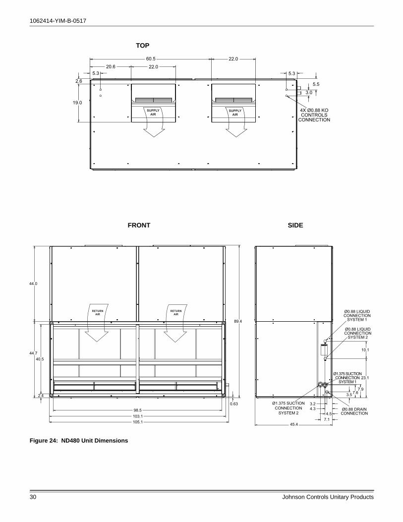
30 Johnson Controls Unitary Products
TOP
4X Ø0.88 KOCONTROLS
CONNECTION
3.0
5.5
5.3
22.060.5
22.020.65.3
2.6
19.0SUPPLY
AIRSUPPLY
AIR
FRONT SIDE
Figure 24: ND480 Unit Dimensions
44.0
44.740.5
2.4
98.5103.1
0.63
89.4
10.1
23.1
7.97.63.5
3.24.3
4.57.1
45.4
Ø0.88 LIQUIDCONNECTION
SYSTEM 1
Ø0.88 LIQUIDCONNECTION
SYSTEM 2
Ø1.375 SUCTIONCONNECTION
SYSTEM 1
Ø0.88 DRAINCONNECTION
Ø1.375 SUCTIONCONNECTION
SYSTEM 2
RETURNAIR
RETURNAIR
105.1

1062414-YIM-B-0517
Johnson Controls Unitary Products 31
HORIZONTAL CONFIGURATION
88.288.8
RETURNAIR
SUPPLYAIR
Figure 25: ND480 Unit Dimensions (Continued)

1062414-YIM-B-0517
32 Johnson Controls Unitary Products
TOP
103.123.061.7
23.018.5
2.6
24.9
6.14.6
6.17.8
9.1
Ø0.88 KOCONTROLS
CONNECTION
Ø1.13 KOCONTROLS
CONNECTION
Ø1.38 KOCONTROLS
CONNECTION
DETIAL ASCALE 0.375
(2X TYP)
SEE DETAIL A
SUPPLYAIR
SUPPLYAIR
FRONT SIDE
45.5
45.4
44.0
SUPPLYAIR
SUPPLYAIR
Figure 26: ND600 Unit Dimensions

1062414-YIM-B-0517
Johnson Controls Unitary Products 33
TOP
53.7
FRONT SIDE
54.4
49.5
2.4
2.3
53.7
98.5103.1105.1
RETURNAIR
RETURNAIR
Ø0.88 LIQUIDCONNECTION
SYSTEM 2
Ø0.88 LIQUIDCONNECTION
SYSTEM 1
Ø.88 DRAINCONNECTION
Ø2.13 SUCTIONCONNECTION
SYSTEM 2
Ø2.13 SUCTIONCONNECTION
SYSTEM 1 3.26.77.6
3.47.3
13.3
27.6
10.2
Figure 27: M1CZ600 Evaporator Section Dimensions

1062414-YIM-B-0517
34 Johnson Controls Unitary Products
VERTICAL CONFIGURATION
FRONT SIDE
53.7
54.4
45.5
99.0
97.8
103.1105.1
SUPPLYAIR
SUPPLYAIR
RETURNAIR
RETURNAIR
HORIZONTAL CONFIGURATION
98.4
97.2
SUPPLYAIR
RETURNAIR
NAMEPLATE
Figure 28: ND600 Air Handler & M1CZ600 Evaporator Coil Dimensions

1062414-YIM-B-0517
Johnson Controls Unitary Products 35
Table 16: Unit Connection Sizes
Maintenance
Filters must be cleaned or replaced as often as necessary to assure good airflow and filtration.
To remove filters through the sides of the unit, remove either the solid side panel on the piping end, or the larger side panel on the end opposite the piping.
To remove the filters from the front of the unit, loosen 2 screws and raise the top filter retainer. The upper filters can be lifted over the center filter lip. Three wing nuts are provided under the center filter retainer. Remove these and a part of the center filter support, giving access to the bottom filters.
Drain pan(s) should be inspected regularly to assure proper drainage.
The evaporator blower bearings and blower motor bearings are permanently lubricated.
Model NC300 ND360 ND480 ND600 M1CZ600ADimensions (inches)
Length 100.1 100.1 103.1 103.1 103.1
Width 38.1 38.1 45.4 45.5 53.7
Height 74.6 74.7 89.4 45.4 54.4
System DataNo. Refrigeration Circuits 1 2 2 2
Suction Line OD (in.) 2 1/8 1 1/8 1 3/8 - 2 1/8
Liquid Line OD (in.) 7/8 7/8 7/8 - 7/8
Power Wiring Knockout 7/8 7/8 7/8 1 3/8 -
Control Wiring Knockout 1 1/8 7/8 7/8 7/8 -
Drain Line 7/8 7/8 7/8 - 7/8
Blower OutletNumber 2 2 2 2 -
Width 19.0 19.0 19.0 24.9 -
Length 22.0 22.0 22.0 23.0 -
Return Air InletWidth 33.2 33.2 40.5 - 49.5
Length 95.6 95.6 98.5 - 98.5

1062414-YIM-B-0517
36 Johnson Controls Unitary Products
Typical Wiring Diagrams
Figure 29: Typical NC300 Indoor Unit Wiring Diagram

1062414-YIM-B-0517
Johnson Controls Unitary Products 37
Figure 30: Typical ND360, 480 & 600 Indoor Unit Wiring Diagram (Contactor)

1062414-YIM-B-0517
38 Johnson Controls Unitary Products
Figure 31: Typical Field Wiring Diagram - NC300 Evaporator Unit with YC300 Condenser Unit
NOTE: On non NC/ND Evaporator models, isolation relays must be installed to avoid overloading on 75 VA transformers on the condensing unit.
Figure 32: Typical NC300 Liquid Line Solenoid Wiring
W1 W2 Y1 G Y2 0CC CX R SD-24
SE CONTROL BOARD THERMOSTAT CONNECTIONSTB2
TB1
CONDENSER CONTROL BOX
EVAPORATOR CONTROL BOX
THERMOSTAT TWO STAGE COOL
R C Y1 Y2 G W1 W2
C S1 S2 G1 G2 66 60 X
C S1 S2 G1 G2 66 60 X
219 / Y218 / BR
1LLS
VALVE SYS 2BLK
BLK
C O I L

1062414-YIM-B-0517
Johnson Controls Unitary Products 39
Figure 33: Typical Field Wiring Diagram ND360/480 Evaporator Units, ND600 Air Handler and M1CZ600A Evaporator Coil when Matched with YD360/480/600 Condenser
NOTE: On non ND evaporator models, isolation relays must be installed to avoid overloading on 75VA transformers on the condensing unit.
Figure 34: Typical ND360/480 & M1CZ600A Liquid Line Solenoid

1062414-YIM-B-0517
40 Johnson Controls Unitary Products
Figure 35: Typical Liquid Line Solenoid Wiring
Standard Terminal Block on NC300, ND360/480 and ND600 with M1CZ600A models. On non NC/ND models isolation relays must be installed to avoid overloading on 75 VA transformer on condensing unit.
Non NC/ND units may not include any or all of the components required to wire the unit. Use the diagram as general reference only.
Primary side of transformer connect to line side of power supply.
Primary side of transformer connect to line side of power supply.

1062414-YIM-B-0517
Johnson Controls Unitary Products 41
Start-Up Sheet
START-UP & SERVICE DATA INSTRUCTION
START-UP CHECKLISTDate: _______________________________________________________________________________________________________
Job Name: __________________________________________________________________________________________________
Customer Name: _____________________________________________________________________________________________
Address: ____________________________________________________________________________________________________
City: ______________________________ State: ______________________________ Zip: ________________________________
Evaporator Model Number: _______________________________ Serial Number: __________________________________________
Condenser Model Number: _______________________________ Serial Number: __________________________________________
Qualified Start-up Technician: _________________________________ Signature: _________________________________________
HVAC Contractor: _________________________________________________________ Phone: _____________________________
Address: ____________________________________________________________________________________________________
Contractor’s E-mail Address: ____________________________________________________________________________________
Electrical Contractor: _________________________________________________________ Phone:___________________________
Distributor Name: ___________________________________________________________ Phone: ___________________________
WARRANTY STATEMENT
Johnson Controls/UPG is confident that this equipment will operate to the owner's satisfaction if the proper procedures are followed and checks are made at initial start-up. This confidence is supported by the 30 day dealer protection coverage portion of our standard warranty policy which states that Johnson Controls/UPG will cover parts and labor on new equipment start-up failures that are caused by a defect in factory workmanship or material, for a period of 30 days from installation. Refer to current standard warranty policy and warranty manual found on UPGnet for details.
In the event that communication with Johnson Controls/UPG is required regarding technical and/or warranty concerns, all parties to the discussion should have a copy of the equipment start-up sheet for reference. A copy of the original start-up sheet should be filed with the Technical Services Department.
The packaged unit is available in constant or variable air volume versions with a large variety of custom options and accessories available. Therefore, some variation in the startup procedure will exist depending upon the products capacity, control system, options and accessories installed.
This start-up sheet covers all startup check points common to all package equipment. In addition it covers essential startup check points for a number of common installation options. Depending upon the particular unit being started not all sections of this startup sheet will apply. Complete those sections applicable and use the notes section to record any additional information pertinent to your particular installation.
Warranty claims are to be made through the distributor from whom the equipment was purchased.
EQUIPMENT STARTUP
Use the local LCD or Mobile Access Portal (MAP) Gateway to complete the start-up.
A copy of the completed start-up sheet should be kept on file by the distributor providing the equipment and a copy sent to:
Johnson Controls/UPGTechnical Services Department5005 York DriveNorman, OK 73069
COMMERCIAL SPLIT SYSTEMS7.5 To 50.0 TON

1062414-YIM-B-0517
42 Johnson Controls Unitary Products
1034350-UCL-D-0817
2 Unitary Products Group
SAFETY WARNINGS
The inspections and recording of data outlined in this procedure are required for start-up of Johnson Controls/UPG's packaged products. Industry recognized safety standards and practices must be observed at all times. General industry knowledge and experience are required to assure technician safety. It is the responsibility of the technician to assess all potential dangers and take all steps warranted to perform the work in a safe manner. By addressing those potential dangers, prior to beginning any work, the technician can perform the work in a safe manner with minimal risk of injury.
NOTE: Read and review this entire document before beginningany of the startup procedures.
DESIGN APPLICATION INFORMATION
This information will be available from the specifying engineer who selected the equipment. If the system is a VAV system the CFM will be the airflow when the remote VAV boxes are in the
full open position and the frequency drive is operating at 60 HZ. Do not proceed with the equipment start-up without the design CFM information.
Design Supply Air CFM: __________________________ Design Return Air CFM: ______________________________________
Design Outdoor Air CFM At Minimum Pos ition: _______________________________________________________
Tota l Exte rna l S ta tic Pressure : ____________________________________________________________________
Supply S ta tic Pressure : _________________________________________________________________________
Return S ta tic Pressure : _________________________________________________________________________
Des ign Building S ta tic Pressure : __________________________________________________________________
ADDITIONAL APPLICATION NOTES FROM SPECIFYING ENGINEER:
Lethal voltages are present during some start-up checks. Extreme caution must be used at all times.
Moving parts may be exposed during some startup checks. Extreme caution must be used at all times.

1062414-YIM-B-0517
Johnson Controls Unitary Products 43
1034350-UCL-D-0817
Unitary Products Group 3
REFERENCE
General Inspection Completed See NotesUnit inspected for shipping, storage, or rigging damage
Unit installed with proper clearances
Unit installed within slope limitations
Refrigeration system checked for gross leaks (presence of oil)
Terminal screws and wiring connections checked for tightness
Filters installed correctly and clean
Condensate drain trapped properly, refer to Installation Manual
All field wiring (power and control) complete
Refrigerant Line Inspection System 1 System 2
Is Condenser below Evaporator? Yes No Yes No
Total Line Length end to end. _______ Ft. _______ Ft.
Vertical Lift in Ft. _______ Ft. _______ Ft.
Vertical Fall in Ft. _______ Ft. _______ Ft.
Number of Elbows? _______ Ea. _______ Ea.
Liquid Line Size _______ Ea. _______ Ea.
Suction Line Size _______ Ea. _______ Ea.
Solenoid Valve? Yes No Yes No
Check Valves? Yes No Yes No
Check Valves / Solenoid arrangements installed as per UPG Piping Guide Yes No Yes No
Oil Separator ? Yes No Yes No
Accumulator ? Yes No Yes No
TXV - Hard shutoff Yes No Yes No
Heatpump Yes No Yes No
Air Moving Inspection Completed See NotesAlignment of drive components
Belt tension adjusted properly
Blower pulleys tight on shaft, bearing set screws tight, wheel tight to shaft
Pressure switch or transducer tubing installed properly

1062414-YIM-B-0517
44 Johnson Controls Unitary Products
1034350-UCL-D-0817
4 Unitary Products Group
Operating Measurements - Air Flow
ELECTRICAL DATAT1 - T2 ____________________________ Volts
Control Voltage ______________________ Volts
T2 - T3 ____________________________ Volts
T1 - T3 ____________________________ Volts
Fan operates with proper rotation (All VFD equipped units with the optional Manual Bypass must be phased for correct blower rotation with the Bypass switch set in the LINE position) ID Fans Exh. Fans Cond. Fans
Pressure drop across dry evaporator coil (At maximum design CFM) 1
1. Consult the proper airflow to pressure drop table to obtain the actual airflow at the measured pressure differential.
IWC
External Static Pressure IWC
Return Static Pressure IWC
Supply Static Pressure IWC
Supply Air CFM Using Dry Coil Chart CFM
Final Adjusted Supply Air CFM2
2. Was a motor pulley adjustment or change required to obtain the correct airflow?Was it necessary to increase of decrease the airflow to meet the design conditions?If the motor pulley size was changed, measure the outside diameters of the motor and blower pulleys and record those diameters here;
Blower Motor HP _______________________________FLA________ RPM________
Pulley Pitch Diameter ______________Turns Out________ Final Turns Out________
Blower Pulley Pitch Diameter ________________ Fixed Sheave_________________
CFM
Device Nameplate Measured List All Three Amperages
Supply Fan Motor1,2
1. VAV units with heat section - simulate heat call to drive VAV boxes and VFD/IGV to maximum design airflow position.2. VAV units without hea t section - VAV boxes mus t be se t to maximum des ign a irflow pos ition. Notes above apply for 3rd party application only.
AMPS AMPS
Condenser Fan #1 AMPS AMPS
Condenser Fan #2 (if equipped) AMPS AMPS
Condenser Fan #3 (if equipped) AMPS AMPS
Condenser Fan #4 (if equipped) AMPS AMPS
Compressor #1 AMPS AMPS
Compressor #2 (if equipped) AMPS AMPS
Compressor #3 (if equipped) AMPS AMPS
Compressor #4 (if equipped) AMPS AMPS

1062414-YIM-B-0517
Johnson Controls Unitary Products 45
1034350-UCL-D-0817
Unitary Products Group 5
OPERATING MEASUREMENTS - COOLING
REFRIGERANT SAFETIES
OPERATING MEASUREMENTS ELECTRIC HEATING
Heater kW ____________kW Heater Voltage, Nameplate ____________ Volts
Heater Model Number: _______________________________
Serial Number: ______________________________________
Stage Discharge Pressure
Discharge Temp.
Liquid LinePressure At
Service Valve
Liquid Line Temp.1
1. Liquid line temperature should be taken before filter/drier.
Subcooling2
2. Subtract 10 psi from discharge pressure for estimated liquid line pressure
Suction Pressure
Suction Temp. Superheat
First3
3. If Rawal valve installed, contact Technical Service.
# ° # ° ° # ° °Second (if equipped) # ° # ° ° # ° °Third (if equipped) # ° # ° ° # ° °Fourth (if equipped) # ° # ° ° # ° °Heat Pump 1st Stage # ° # ° ° # ° °
Outside air temperature ________________ db °F ________________ wb °F ________________ RH%
Return Air Temperature ________________ db °F ________________ wb °F ________________ RH%
Mixed Air Temperature ________________ db °F ________________ wb °F ________________ RH%
Supply Air Temperature ________________ db °F ________________ wb °F ________________ RH%
Action Completed See NotesProve Compressor Rotation (3 phase only) by guage pressure
Prove High Pressure Safety, All Systems
Prove Low Pressure Safety, All Systems
Heater Nameplate Measured List All Three Amperages
Stage 1 _________AMPS _________AMPS _________AMPS _________AMPS
Stage 2 _________AMPS _________AMPS _________AMPS _________AMPS
Stage 3 _________AMPS _________AMPS _________AMPS _________AMPS
Stage 4 _________AMPS _________AMPS _________AMPS _________AMPS
Checked Heater Limit Yes No
Air Moving Switch Installed? Yes No

Subject to change without notice. Printed in U.S.A. 1062414-YIM-B-0517Copyright © 2017 by Johnson Controls, Inc. All rights reserved. Supersedes: 1062414-YIM-A-0913
York International Corporation5005 York Drive
Norman, OK 73069
OPERATIONAL MEASUREMENTS - STAGING CONTROLS
FINAL - INSPECTION
OBSERVED PRODUCT DEFICIENCIES & CONCERNS:
________________________________________________________________________________________________________
________________________________________________________________________________________________________
________________________________________________________________________________________________________
________________________________________________________________________________________________________
________________________________________________________________________________________________________
________________________________________________________________________________________________________
________________________________________________________________________________________________________
________________________________________________________________________________________________________
________________________________________________________________________________________________________
________________________________________________________________________________________________________
________________________________________________________________________________________________________
________________________________________________________________________________________________________
________________________________________________________________________________________________________
________________________________________________________________________________________________________
________________________________________________________________________________________________________
Verify Proper Operation of Heating/Cooling Staging ControlsCreate a cooling demand at the Thermostat, BAS System or Smart Equipment™Verify that cooling/economizer stages are energized.
Create a heating demand at the Thermostat, BAS System or Smart Equipment™Verify that heating stages are energized.
Verify Proper Operation of the Variable Frequency Drive (If Required)Verify that motor speed modulates with duct pressure change.
Verify that all operational control set points have been set to desired valueScroll through all setpoints and change as may be necessary to suit the occupant requirements.
Verify that all option parameters are correctScroll through all option parameters and ensure that all installed options are enabled in the software and all others are disabled in the software. (Factory software settings should match the installed options)
Verify that all access panels have been closed and secured
Save a backup file from the unit control board onto a USB flash drive.
Related Documents


![PACKAGEHEATPUMPSFEATURING INDUSTRYSTANDARDR-410A … · 2020. 3. 17. · []indicatesmetricconversion installationinstructions packageheatpumpsfeaturing industrystandardr-410a refrigerant](https://static.cupdf.com/doc/110x72/5ff73ec723717515a65c591b/packageheatpumpsfeaturing-industrystandardr-410a-2020-3-17-indicatesmetricconversion.jpg)


