Welcome message from author
This document is posted to help you gain knowledge. Please leave a comment to let me know what you think about it! Share it to your friends and learn new things together.
Transcript

© 2010 PACCAR INC - All Rights Reserved
This manual illustrates and describes the operation of features or equipment which may be either standard or optional on this vehicle. This manual may also include a description of features and equipment which are no longer available or were not ordered on this vehicle. Please disregard any illustrations or descriptions relating to the features or equipment which are not on this vehicle.
Peterbilt reserves the right to discontinue, change specifications, or change the desing of its vehicles at any time without notice and without incurring any obligation.
The information contained in this manual is proprietaary to Peterbilt. Reproduction, in whole or in part, by any means is strictly prohibited without prio written authorication from PACCAR Inc.
Quick Table of Contents
Introduction . . . . . . . . . . . . . . . . . . 1
Cab And Frame Access . . . . . . . . . . . . 6
Getting To Your Engine . . . . . . . . . . . . . . 11
Controls And Displays. . . . . . . . . . . . . . . . . . . 14
Seat And Restraint Systems . . . . . . . . . . . . . . . . . 75
Driver’s Checklists . . . . . . . . . . . . . . . . . . . . . . . . . . . 88
Starting And Operating The Vehicle . . . . . . . . . . . . . . . . . . 93
Maintenance and Service . . . . . . . . . . . . . . . . . . . . . . . . . . 143
Vehicle Identification . . . . . . . . . . . . . . . . . . . . . . . . . . . . . . . . . . . 229
Consumer Information . . . . . . . . . . . . . . . . . . . . . . . . . . . . . . . . . . . . . 230
Subject Index . . . . . . . . . . . . . . . . . . . . . . . . . . . . . . . . . . . . . . . . . . . . . . . 233
Y53-6032.book Page 2 Monday, May 24, 2010 3:37 PM

PART 1: INTRODUCTION HOW TO FIND WHAT YOU WANT
(R05/10) Y53-6032 – 1 –
PART 1: INTRODUCTION
This manual contains useful information for the safe andefficient operation of your Peterbilt Model 587. It also pro-vides information on maintaining your vehicle in the bestcondition, with an outline for performing safety checks andbasic preventive maintenance inspections.
We have tried to present the information you’ll need tolearn about your vehicle’s functions, controls, and opera-tion—and to present it as clearly as possible. We hopeyou’ll find this manual easy to use.
Please remember, though—this manual is not a trainingmanual. It can’t tell you everything you need to knowabout driving your Peterbilt vehicle. For that you need agood training program or truck driving school. If you havenot been trained, get the proper training before you drive.Only qualified drivers should drive this vehicle.
There will be times when you need to take this manual outof your Peterbilt. When you do, please be sure to return itto the cab when you are finished using it. That way it willbe there when you need it the next time or when you passthe vehicle on to the next user.
How To Find What You WantThere are several tools built into this manual to help youfind what you need quickly and easily.
First is the Quick Table of Contents. Located at the frontof the manual, this lists the main subjects covered andgives page numbers where you can find these subjects.Use the Quick Table of Contents to find information on alarge subject like “Maintenance.”
Cross-referenced citations also help you get the informa-tion you need. If some other part of the manual containsfurther information on the subject you are reading about,we’ll indicate that in a cross-reference like this: (See“PART 6: DRIVER’S CHECKLIST”). You won’t have to gosearching for more information.
Finally you’ll find a helpful Subject Index. It’s in the backof the manual and alphabetically lists the subjects cov-ered. So if you want information on brakes, for example,just look under Brake in the Subject Index. You’ll find allthe pages listed where brakes or braking are discussed.
Y53-6032.book Page 1 Monday, May 24, 2010 3:37 PM

A SPECIAL WORD ABOUT REPAIRS PART 1: INTRODUCTION
– 2 – Y53-6032 (R05/10)
A Special Word About RepairsYour Peterbilt dealer’s service center is the best place tohave your vehicle repaired. You can find Peterbilt dealers allover the country with the equipment and trained personnelto get you back on the road quickly—and keep you there.
Your vehicle is a complex machine. Anyone attemptingrepairs on it needs good mechanical training and theproper tools. If you are sure you have these requirements,then you can probably perform some repairs yourself.However, all warranty repairs must be performed by anauthorized Peterbilt service facility. If you aren’t an experi-enced mechanic, or don’t have the right equipment,please leave all repairs to an authorized service facility.They are the ones equipped to do the job safely and cor-rectly.
WARNING! Attempting repair work without suf-ficient training, service manuals, and the propertools can be dangerous for yourself and others.You could be injured or you could make yourtruck unsafe and cause death or serious injury.Do only those tasks you are fully qualified to do.
Maintenance Manuals. If you do decide to do any com-plex repair work, you’ll need the Peterbilt Maintenancemanuals. Order them from your authorized dealer. Pleaseprovide your Chassis Serial Number when you order, tobe sure you get the correct manuals for your vehicle. Allowabout four weeks for delivery. There will be a charge forthese manuals.
Final Chassis Bill of Material. A complete, nonillustratedcomputer printout listing of the parts used to custom-buildyour Peterbilt vehicle is available through the Peterbiltdealer from whom your purchased your vehicle.
WARNING! Modifying your vehicle can make itunsafe. Some modifications can affect yourtruck’s electrical system, stability, or otherimportant functions. Before modifying yourvehicle, check with your dealer to make sure itcan be done safely.
Additional Sources of InformationOperator’s manuals are also supplied by the manufactur-ers of components such as the engine, seats, transmis-sion, and radio in your Peterbilt. If you are missing any ofthese manuals, ask your Peterbilt dealer to supply them.
Y53-6032.book Page 2 Monday, May 24, 2010 3:37 PM
PART 1: INTRODUCTION SAFETY SIGNALS
(R05/10) Y53-6032 – 3 –
Another place to learn more about trucking is a local truckdriving school. Contact one near you to find out whatkinds of instruction it offers.
Federal agencies such as The National Highway TrafficSafety Administration and the Federal Motor CarrierSafety Administration also have information and variousagencies in state governments are sources for regulationsthat differ from state to state.
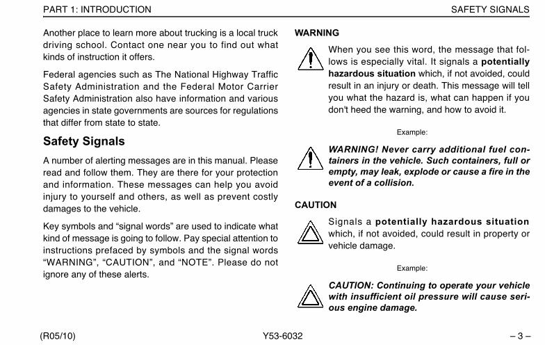
Safety SignalsA number of alerting messages are in this manual. Pleaseread and follow them. They are there for your protectionand information. These messages can help you avoidinjury to yourself and others, as well as prevent costlydamages to the vehicle.
Key symbols and “signal words” are used to indicate whatkind of message is going to follow. Pay special attention toinstructions prefaced by symbols and the signal words“WARNING”, “CAUTION”, and “NOTE”. Please do notignore any of these alerts.
WARNING
When you see this word, the message that fol-lows is especially vital. It signals a potentiallyhazardous situation which, if not avoided, couldresult in an injury or death. This message will tellyou what the hazard is, what can happen if youdon't heed the warning, and how to avoid it.
Example:
WARNING! Never carry additional fuel con-tainers in the vehicle. Such containers, full orempty, may leak, explode or cause a fire in theevent of a collision.
CAUTION
Signals a potentially hazardous situationwhich, if not avoided, could result in property orvehicle damage.
Example:
CAUTION: Continuing to operate your vehiclewith insufficient oil pressure will cause seri-ous engine damage.
Y53-6032.book Page 3 Monday, May 24, 2010 3:37 PM
VEHICLE SAFETY PART 1: INTRODUCTION
– 4 – Y53-6032 (R05/10)
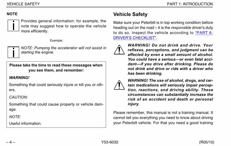
NOTE
Provides general information: for example, thenote may suggest how to operate the vehiclemore efficiently.
Example:
NOTE: Pumping the accelerator will not assist instarting the engine.
Vehicle SafetyMake sure your Peterbilt is in top working condition beforeheading out on the road—it is the responsible driver's dutyto do so. Inspect the vehicle according to “PART 6:DRIVER’S CHECKLIST”.
WARNING! Do not drink and drive. Yourreflexes, perceptions, and judgment can beaffected by even a small amount of alcohol.You could have a serious—or even fatal acci-dent—if you drive after drinking. Please donot drink and drive or ride with a driver whohas been drinking.
WARNING! The use of alcohol, drugs, and cer-tain medications will seriously impair percep-tion, reactions, and driving ability. Thesecircumstances can substantially increase therisk of an accident and death or personalinjury.
Please remember, this manual is not a training manual. Itcannot tell you everything you need to know about drivingyour Peterbilt vehicle. For that you need a good training
Please take the time to read these messages when you see them, and remember:
WARNING!
Something that could seriously injure or kill you or oth-ers.
CAUTION:
Something that could cause property or vehicle dam-age.
NOTE:
Useful information.
Y53-6032.book Page 4 Monday, May 24, 2010 3:37 PM
PART 1: INTRODUCTION VEHICLE SAFETY
(R05/10) Y53-6032 – 5 –
program or truck driving school. If you have not beentrained, get the proper training before you drive. Onlyqualified drivers should drive this vehicle.
Safe driving is only possible with the proper concentrationon the driving task. Keep distraction to a minimum toimprove your concentration. Examples of distractionsmay include radio controls, GPS navigation controls, cel-lular telephone calls, cellular text messages, reading orreaching for something on the floor. Minimizing your dis-tractions will improve safe driving and will help avoid anaccident involving death or personal injury.
Be aware of local regulations that may prohibit the use ofcellular telephones while driving. In addition to being anunsafe practice, it may be against local ordinances to usecellular devices while operating the vehicle.
Every new Peterbilt vehicle is designed to conform to allFederal Motor Vehicle Safety Standards applicable at thetime of manufacture. However, even with these safety fea-tures, continued safe and reliable operation dependsgreatly upon regular vehicle maintenance. The vehiclemust be operated within the range of its mechanical capa-bilities and the limits of its load ratings. (See the Tire andRim Weight Ratings label on the driver's door edge.)
Y53-6032.book Page 5 Monday, May 24, 2010 3:37 PM

PART 2: GETTING INTO & OUT OF THE CAB AND FRAME ACCESS
– 6 – Y53-6032 (R05/10)
PART 2: GETTING INTO & OUT OF THE CAB AND FRAME ACCESS
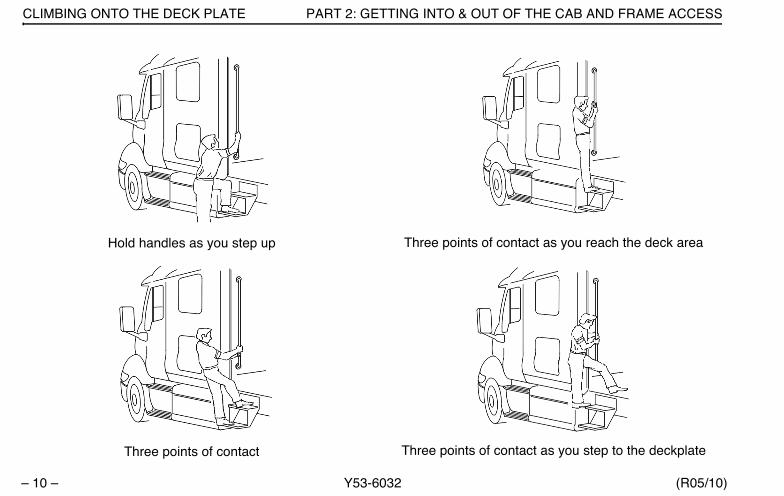
Be careful whenever you get into or out of your vehicle’scab. Always maintain at least three points of contact withyour hands on the grab handles and your feet on thesteps.
WARNING! Do not jump out of the cab or getinto the cab without proper caution. You couldslip or fall, possibly suffering death or seriousinjury. You could slip and fall if the steps arewet or icy, or if you step in fuel, oil, grease,snow or mud.
The illustrations that follow show the best ways to enterand exit a cab.
Vehicle With External Grab Handle
02958-A
Y53-6032.book Page 6 Monday, May 24, 2010 3:37 PM

PART 2: GETTING INTO & OUT OF THE CAB AND FRAME ACCESS DOOR LOCK AND KEYS
(R05/10) Y53-6032 – 7 –
Vehicle Without External Grab Handle
Door Lock and KeysDoors can be locked from the inside by using the lock but-ton. Close the door then push the button down to lock.Doors automatically unlock when you open them frominside, and can be locked from the outside with the keyonly. To lock or unlock the doors from outside the cab,insert the key in the lock. Turn the key toward the rear tolock; forward to unlock.
WARNING! To help lessen the chance and/orseverity of death or personal injury in case ofan accident, always lock the doors while driv-ing. Along with using the lap shoulder beltsproperly, locking the doors helps preventdoors from inadvertently opening and occu-pants from being ejected from the vehicle.
Remote Keyless Entry (optional)This vehicle may be equipped with a Remote KeylessEntry (RKE) system that adds security and convenienceto your vehicle. The system will lock or unlock the driver’sdoor and passenger’s door with the key fob and alert youwith parking lights when the selected door’s are locked orunlocked. The system includes two key fobs that providesecure rolling code technology that prevents someonefrom recording the entry signal.
Operation
To unlock the driver’s door, press the UNLOCK buttononce. The driver's door will unlock and the parking lightswill come on for 40 seconds.
To unlock the passenger’s door press the UNLOCK buttononce and press again within 5 seconds.
02958-B
Y53-6032.book Page 7 Monday, May 24, 2010 3:37 PM

DOOR LOCK AND KEYS PART 2: GETTING INTO & OUT OF THE CAB AND FRAME ACCESS
– 8 – Y53-6032 (R05/10)
To lock both doors press the LOCK button. The doors willlock and the parking lights will come on for 2 seconds. Ifthe doors are open they will not lock. The range of theRKE system should be approximately 30 ft. This will bereduced if it is operated close to other RF sources such asTV/radio transmitters and cell towers.
Batteries
The key fob uses one CR2032, 3V battery. Batteriesshould last approximately three years, depending on use.Consistently reduced range is an indicator that the batteryneeds replacement. Batteries are available at most dis-count, hardware and drug stores.
The battery is located under the back cover of the key fob.Be sure to synchonize the key fob every time you replacethe batteries.
Synchronization
The key fob may need to be synchronized to the truckwhen the battery is replaced or when the key fob has notbeen used for an extended period time.
To Synchronize A Key Fob
1. Hold the key fob near the receiver.
NOTE: The receiver is located behind theSpeedometer/Tachometer cluster assembly.
2. Press and hold both the Lock and Unlock buttons atthe same time for approximately 7 seconds.
3. When the key fob is resynchronized, the doors willlock then immediately unlock.
4. If the fob fails to synchronize, it could be programmedto a different truck or could have failed. Contact yourdealer to re-program your key fob.
Y53-6032.book Page 8 Monday, May 24, 2010 3:37 PM

PART 2: GETTING INTO & OUT OF THE CAB AND FRAME ACCESS CLIMBING ONTO THE DECK PLATE
(R05/10) Y53-6032 – 9 –
Climbing Onto the Deck PlateWhen you are climbing onto and off the deck plate, main-tain at least three points of contact with your hands on thegrab handles and your feet on the steps.
NOTE: Any alteration (adding bulkheads, head-ache racks, tool boxes, etc.) behind the cab orsleeper that affects the utilization of grab handles,deck plates, or frame access steps installed byPeterbilt must comply with FMCSR 399.
WARNING! Do not step on vehicle compo-nents without antiskid surfaces or use com-ponents not designed for entry-and-exit use.You could fall and kill or injure yourself if youstep onto a slippery surface. For example:• Do not step onto the surface of a fuel tank.
A fuel tank is not a step. The tank surfacecan get very slippery, and you might not beable to prevent a fall.
• Use only the steps and handholds provided,not chain hooks, quarter fenders, etc.
• Do not climb onto and off the deck plate—use steps and grab handle provided. If thereis no deck plate, or if proper steps and grabhandles are not provided, do not climb ontothe area behind the cab.
• Do not climb onto or stand on the framerails. The frame rails are very slippery andcould cause you to fall, resulting in death orpersonal injury.
• Always reinstall steps before entering thecab or accessing the deck plate. Withoutsteps, you could slip and fall, resulting inpossible injury to yourself.
FCC ID: L2C0031T IC: 3432A-0031TFCC ID: L2C0032R IC: 3432A-0032R
This device complies with Part 15 of the FCC Rules and with RSS-210 of Industry Canada. Operation is subject to the following two condi-tions:
1. This device may not cause harmful interference, and2. This device must accept any interference received, including
interference that may cause undesired operation.
WARNING: Changes or modifications not expressively approved by the party responsible for compliance could void the user's authority to operate the equipment. The term “IC:” before the radio certification number only sig-nifies that Industry Canada technical specifications were met.
Y53-6032.book Page 9 Monday, May 24, 2010 3:37 PM
CLIMBING ONTO THE DECK PLATE PART 2: GETTING INTO & OUT OF THE CAB AND FRAME ACCESS
– 10 – Y53-6032 (R05/10)
Hold handles as you step up
Three points of contact
Three points of contact as you reach the deck area
Three points of contact as you step to the deckplate
Y53-6032.book Page 10 Monday, May 24, 2010 3:37 PM

PART 3: GETTING TO YOUR ENGINE HOOD HOLD DOWNS
(R05/10) Y53-6032 – 11 –
PART 3: GETTING TO YOUR ENGINE
Hood Hold Downs Hood hold downs keep a hood from opening unexpect-edly.
CAUTION: A hood not latched securely couldopen during operation and cause vehicledamage. Be sure to latch the hood securely.
Hood TiltFollow this procedure to tilt the hood.
WARNING! A pivoting hood could hurt some-one or be damaged itself. Before opening orclosing the hood, be sure there are no peopleor objects in the way. Failure to stand in aposition of safety can cause death or personalinjury.
1. To open your hood, unlock the hood hold downs byunlatching them. Put one hand on the top of the hoodfront, one foot on the bumper, and one foot on theground. Tilt the hood forward.
LATCHED
UNLATCHED
Y53-6032.book Page 11 Monday, May 24, 2010 3:37 PM
HOOD TILT PART 3: GETTING TO YOUR ENGINE
– 12 – Y53-6032 (R05/10)
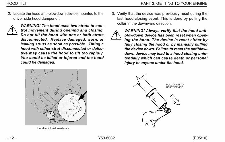
2. Locate the hood anti-blowdown device mounted to thedriver side hood dampener.
WARNING! The hood uses two struts to con-trol movement during opening and closing.Do not tilt the hood with one or both strutsdisconnected. Replace damaged, worn, orleaking struts as soon as possible. Tilting ahood with either strut disconnected or defec-tive may cause the hood to tilt too rapidly.You could be killed or injured and the hoodcould be damaged.
3. Verify that the device was previously reset during thelast hood closing event. This is done by pulling thecollar in the downward direction.
WARNING! Always verify that the hood anti-blowdown device has been reset when open-ing the hood. The device is reset either byfully closing the hood or by manually pullingthe device down. Failure to reset the antiblow-down device may lead to a hood closing unin-tentially which can cause death or personalinjury to anyone under the hood.
Hood antiblowdown device
PULL DOWN TO RESET DEVICE
Y53-6032.book Page 12 Monday, May 24, 2010 3:37 PM

PART 3: GETTING TO YOUR ENGINE HOOD TILT
(R05/10) Y53-6032 – 13 –
4. To close the hood, disengage the hood antiblowdowndevice by pushing it in the upward direction. Thedevice will move about 1/4” up the shaft. You may feela click when the device disengages.
CAUTION: Attempting to close a hood withoutdisengaging the hood antiblowdown devicemay cause equipment or vehicle damage.
5. Firmly push upward and rearward on the hood orna-ment to start the hood tilting backwards. Continue topush until the hood comes is fully closed.
6. Secure the hood latches on both sides of the vehicleto hold the hood in the closed position.
WARNING! If the hood is not latched securely,it could open during operation and cause anaccident involving death or injury. Be sure thehood is latched securely before moving thevehicle.
PUSH UP TO DISENGAGE DEVICE
Y53-6032.book Page 13 Monday, May 24, 2010 3:37 PM
YOUR INSTRUMENT PANEL PART 4: CONTROLS AND DISPLAYS
– 14 – Y53-6032 (R05/10)
PART 4: CONTROLS AND DISPLAYS
This part explains the location of the various features onyour vehicle and describes their function. For informationon using these features in driving, see the paragraphsbelow.
Your Instrument PanelPlease remember that each vehicle is custom-made. Yourinstrument panel may not look exactly like the one in thepictures that follow.
We have tried to describe the most common features andcontrols available, so your vehicle may not have some ofthe ones that appear in this section. You can pick out theparts that apply to you and read them to be fully informedon how your particular vehicle operates.
WARNING! Use extreme caution when usingdevices while driving (such as cellular tele-phones) that distracts you from safe drivingpractices. Failure to properly concentrate onthe driving task can result in an accidentinvolving death or personal injury. Limit theuse of such devices to when it is safe to doso; not while operating the vehicle.
Y53-6032.book Page 14 Monday, May 24, 2010 3:37 PM
PART 4: CONTROLS AND DISPLAYS YOUR INSTRUMENT PANEL
(R05/10) Y53-6032 – 15 –
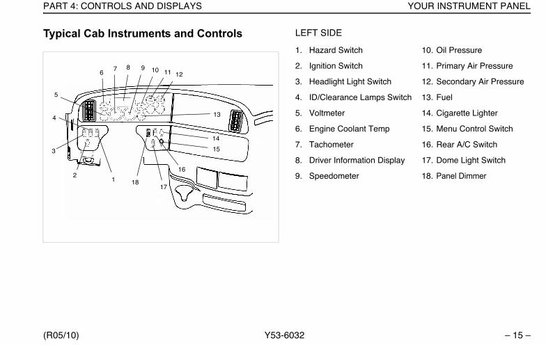
Typical Cab Instruments and Controls LEFT SIDE
1. Hazard Switch 10. Oil Pressure
2. Ignition Switch 11. Primary Air Pressure
3. Headlight Light Switch 12. Secondary Air Pressure
4. ID/Clearance Lamps Switch 13. Fuel
5. Voltmeter 14. Cigarette Lighter
6. Engine Coolant Temp 15. Menu Control Switch
7. Tachometer 16. Rear A/C Switch
8. Driver Information Display 17. Dome Light Switch
9. Speedometer 18. Panel Dimmer18
17
16
15
14
13
121110876
5
4
3
9
21
Y53-6032.book Page 15 Monday, May 24, 2010 3:37 PM
YOUR INSTRUMENT PANEL PART 4: CONTROLS AND DISPLAYS
– 16 – Y53-6032 (R05/10)
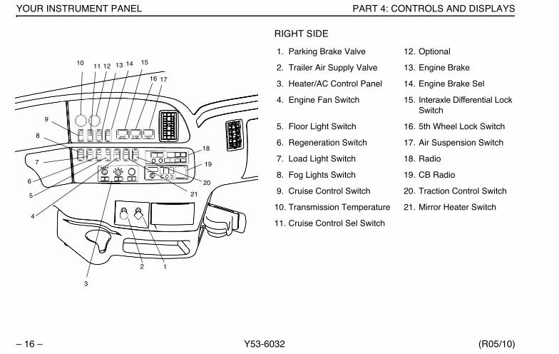
RIGHT SIDE
1. Parking Brake Valve 12. Optional
2. Trailer Air Supply Valve 13. Engine Brake
3. Heater/AC Control Panel 14. Engine Brake Sel
4. Engine Fan Switch 15. Interaxle Differential LockSwitch
5. Floor Light Switch 16. 5th Wheel Lock Switch
6. Regeneration Switch 17. Air Suspension Switch
7. Load Light Switch 18. Radio
8. Fog Lights Switch 19. CB Radio
9. Cruise Control Switch 20. Traction Control Switch
10. Transmission Temperature 21. Mirror Heater Switch
11. Cruise Control Sel Switch
19
18
20
21
12
3
4
5
6
7
8
9
10 11 12 13 14 15
16 17
Y53-6032.book Page 16 Monday, May 24, 2010 3:37 PM

PART 4: CONTROLS AND DISPLAYS INSTRUMENTS AND CONTROLS
(R05/10) Y53-6032 – 17 –
Instruments And ControlsMenu Control Switch (MCS)The MCS is used to navigate the Driver Information Dis-play unit. The Menu Control Switch is located on the D Panelas shown in the illustration below.
The MCS has the following functions:
• Rotating the MCS
– Selecting display
– Setting values
• Pushing the MCS
– Confirming desired selection
Standard Warning Lights and Audible AlarmThe warning lights and audible alarm may indicate a sys-tem malfunction. Check the lights frequently, and respondproperly as soon as you see one go on. These lights couldsave you from a serious accident.
WARNING! Do not ignore a warning light oraudbile alarm. These signals tell you some-thing is wrong with your vehicle. It could be afailure in an important system, such as thebrakes, which could lead to an accidentinvolving death or personal injury. Have theappropriate system checked immediately.
1. Driver Information Display 2. Status Indicator
3. Light Bar
3
2
1
Y53-6032.book Page 17 Monday, May 24, 2010 3:37 PM
INSTRUMENTS AND CONTROLS PART 4: CONTROLS AND DISPLAYS
– 18 – Y53-6032 (R05/10)
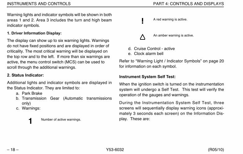
Warning lights and indicator symbols will be shown in bothareas 1 and 2. Area 3 includes the turn and high beamindicator symbols.
1. Driver Information Display:
The display can show up to six warning lights. Warnings do not have fixed positions and are displayed in order of criticality. The most critical warning will be displayed on the top row and to the left. If more than six warnings are active, the menu control switch (MCS) can be used to scroll through the additional warnings.
2. Status Indicator:
Additional lights and indicator symbols are displayed inthe Status Indicator. They are limited to:
a. Park Brake b. Transmission Gear (Automatic transmissions
only)c. Warnings:
d. Cruise Control - activee. Clock alarm bell
Refer to “Warning Light / Indicator Symbols” on page 20for information on each symbol.
Instrument System Self Test:
When the ignition switch is turned on the instrumentationsystem will undergo a Self Test. This test will verify theoperation of the gauges and warnings.
During the Instrumentation System Self Test, threescreens will sequentially display warning icons (approxi-mately 3 seconds each screen) on the Information Dis-play. These are:Number of active warnings.
A red warning is active.
An amber warning is active.
Y53-6032.book Page 18 Monday, May 24, 2010 3:37 PM

PART 4: CONTROLS AND DISPLAYS INSTRUMENTS AND CONTROLS
(R05/10) Y53-6032 – 19 –
Refer to “Warning Light / Indicator Symbols” on page 20for information on each symbol.
Completing this sequence will indicate a successful SelfTest. Have your instrumentation system checked by aqualitfied service technician if does not successfully com-plete.
Audible Alarm:
The audible alarm will sound during the InstrumentationSystem Self Test. The audible alarm will also sound inconjunction with most warning lights. These events
include but are not limited to headlight on, fifth wheel, stopengine, primary/secondary air, and driver door openwarnings.
Optional Lights:
Additional lights may be operational depending on individ-ual vehicle specifications. These will be included in theInstrument System Self Test.
NOTE: Some optional lights may illuminate eventhough your vehicle is not equipped with that par-ticular feature.
First
Second
Third
Y53-6032.book Page 19 Monday, May 24, 2010 3:37 PM
INSTRUMENTS AND CONTROLS PART 4: CONTROLS AND DISPLAYS
– 20 – Y53-6032 (R05/10)
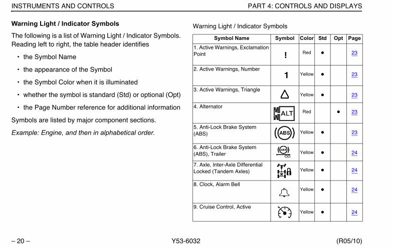
Warning Light / Indicator Symbols
The following is a list of Warning Light / Indicator Symbols.Reading left to right, the table header identifies
• the Symbol Name
• the appearance of the Symbol
• the Symbol Color when it is illuminated
• whether the symbol is standard (Std) or optional (Opt)
• the Page Number reference for additional information
Symbols are listed by major component sections.
Example: Engine, and then in alphabetical order.
Warning Light / Indicator Symbols
Symbol Name Symbol Color Std Opt Page
1. Active Warnings, Exclamation Point Red 23
2. Active Warnings, NumberYellow 23
3. Active Warnings, TriangleYellow 23
4. AlternatorRed 23
5. Anti-Lock Brake System (ABS) Yellow 23
6. Anti-Lock Brake System (ABS), Trailer Yellow 24
7. Axle, Inter-Axle Differential Locked (Tandem Axles) Yellow 24
8. Clock, Alarm BellYellow 24
9. Cruise Control, ActiveYellow 24
Y53-6032.book Page 20 Monday, May 24, 2010 3:37 PM

PART 4: CONTROLS AND DISPLAYS INSTRUMENTS AND CONTROLS
(R05/10) Y53-6032 – 21 –
10. Dump Truck, Body UpYellow 24
11. Dump Truck, Trailer Body UpYellow 25
12. Emissions, Diesel Particu-late Filter (DPF) Yellow 25
13. Emissions, High Exhaust System Temperture (HEST) Yellow 25
14. Emissions, Malfunction Indi-cator Lamp Yellow 26
15. Emission, Diesel Exhaust Fluid Lamp
Yellow26
16. Engine, Check EngineYellow 26
17. Engine, Ether StartGreen 26
18. Engine, HeaterYellow 26
Warning Light / Indicator Symbols
Symbol Name Symbol Color Std Opt Page
19. Engine, Low Coolant LevelYellow 26
20. Engine, OverspeedRed 27
21. Engine, Retarder (Brake)Green 27
22. Engine, Stop EngineRed 27
23. Engine, Wait To StartYellow 27
24. Fifth Wheel, King Pin LockRed 27
25. Fifth Wheel, Slide UnlockedRed 27
26. Lights, High BeamBlue 28
27. Message WaitingGreen 28
Warning Light / Indicator Symbols
Symbol Name Symbol Color Std Opt Page
Y53-6032.book Page 21 Monday, May 24, 2010 3:37 PM

INSTRUMENTS AND CONTROLS PART 4: CONTROLS AND DISPLAYS
– 22 – Y53-6032 (R05/10)
28. Park BrakeRed 28
29. Power Take-off (PTO)Green 28
30. Power Take-off (PTO), Pump Mode Green 28
31. RefrigeratorGreen 28
32. Seat Belt, FastenRed 28
33. Suspension DumpYellow 28
34. Tire InflationYellow 29
35. Transmission, AuxiliaryYellow 29
36. Transmission, CheckRed 29
Warning Light / Indicator Symbols
Symbol Name Symbol Color Std Opt Page
37. Transmission, Do Not ShiftRed 29
38. Transmission, Oil FilterYellow 29
39. Transmission, Oil Tempera-ture High Yellow 29
40. Turn Signal, LeftGreen 29
41. Turn Signal, RightGreen 29
Warning Light / Indicator Symbols
Symbol Name Symbol Color Std Opt Page
Y53-6032.book Page 22 Monday, May 24, 2010 3:37 PM
PART 4: CONTROLS AND DISPLAYS INSTRUMENTS AND CONTROLS
(R05/10) Y53-6032 – 23 –
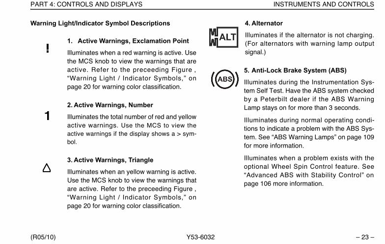
Warning Light/Indicator Symbol Descriptions
1. Active Warnings, Exclamation Point
Illuminates when a red warning is active. Usethe MCS knob to view the warnings that areactive. Refer to the preceeding Figure ,“Warning Light / Indicator Symbols,” onpage 20 for warning color classification.
2. Active Warnings, Number
Illuminates the total number of red and yellowactive warnings. Use the MCS to view theactive warnings if the display shows a > sym-bol.
3. Active Warnings, Triangle
Illuminates when an yellow warning is active.Use the MCS knob to view the warnings thatare active. Refer to the preceeding Figure ,“Warning Light / Indicator Symbols,” onpage 20 for warning color classification.
4. Alternator
Illuminates if the alternator is not charging.(For alternators with warning lamp outputsignal.)
5. Anti-Lock Brake System (ABS)
Illuminates during the Instrumentation Sys-tem Self Test. Have the ABS system checkedby a Peterbilt dealer if the ABS WarningLamp stays on for more than 3 seconds.
Illuminates during normal operating condi-tions to indicate a problem with the ABS Sys-tem. See “ABS Warning Lamps” on page 109for more information.
Illuminates when a problem exists with theoptional Wheel Spin Control feature. See“Advanced ABS with Stability Control” onpage 106 more information.
Y53-6032.book Page 23 Monday, May 24, 2010 3:37 PM
INSTRUMENTS AND CONTROLS PART 4: CONTROLS AND DISPLAYS
– 24 – Y53-6032 (R05/10)
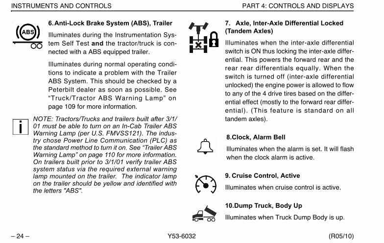
6.Anti-Lock Brake System (ABS), Trailer
Illuminates during the Instrumentation Sys-tem Self Test and the tractor/truck is con-nected with a ABS equipped trailer.
Illuminates during normal operating condi-tions to indicate a problem with the TrailerABS System. This should be checked by aPeterbilt dealer as soon as possible. See“Truck/Tractor ABS Warning Lamp” onpage 109 for more information.
NOTE: Tractors/Trucks and trailers built after 3/1/01 must be able to turn on an In-Cab Trailer ABSWarning Lamp (per U.S. FMVSS121). The indus-try chose Power Line Communication (PLC) asthe standard method to turn it on. See “Trailer ABSWarning Lamp” on page 110 for more information.On trailers built prior to 3/1/01 verify trailer ABSsystem status via the required external warninglamp mounted on the trailer. The indicator lampon the trailer should be yellow and identified withthe letters "ABS".
7. Axle, Inter-Axle Differential Locked (Tandem Axles)
Illuminates when the inter-axle differentialswitch is ON thus locking the inter-axle differ-ential. This powers the forward rear and therear rear differentials equally. When theswitch is turned off (inter-axle differentialunlocked) the engine power is allowed to flowto any of the 4 drive tires based on the differ-ential effect (mostly to the forward rear differ-ential). (This feature is standard on alltandem axles).
8.Clock, Alarm Bell
Illuminates when the alarm is set. It will flashwhen the clock alarm is active.
9. Cruise Control, Active
Illuminates when cruise control is active.
10.Dump Truck, Body Up
Illuminates when Truck Dump Body is up.
Y53-6032.book Page 24 Monday, May 24, 2010 3:37 PM
PART 4: CONTROLS AND DISPLAYS INSTRUMENTS AND CONTROLS
(R05/10) Y53-6032 – 25 –
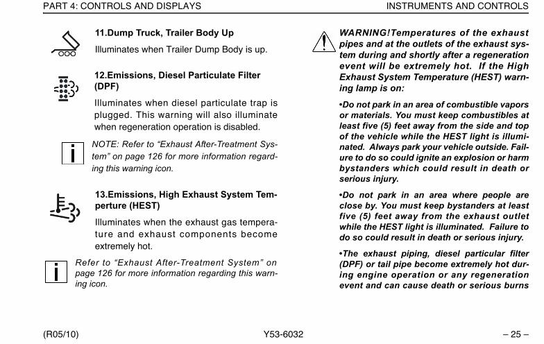
11.Dump Truck, Trailer Body Up
Illuminates when Trailer Dump Body is up.
12.Emissions, Diesel Particulate Filter (DPF)
Illuminates when diesel particulate trap isplugged. This warning will also illuminatewhen regeneration operation is disabled.
NOTE: Refer to “Exhaust After-Treatment Sys-tem” on page 126 for more information regard-ing this warning icon.
13.Emissions, High Exhaust System Tem-perture (HEST)
Illuminates when the exhaust gas tempera-ture and exhaust components becomeextremely hot.
Refer to “Exhaust After-Treatment System” onpage 126 for more information regarding this warn-ing icon.
WARNING!Temperatures of the exhaustpipes and at the outlets of the exhaust sys-tem during and shortly after a regenerationevent will be extremely hot. If the HighExhaust System Temperature (HEST) warn-ing lamp is on:
•Do not park in an area of combustible vaporsor materials. You must keep combustibles atleast five (5) feet away from the side and topof the vehicle while the HEST light is illumi-nated. Always park your vehicle outside. Fail-ure to do so could ignite an explosion or harmbystanders which could result in death orserious injury.
•Do not park in an area where people areclose by. You must keep bystanders at leastfive (5) feet away from the exhaust outletwhile the HEST light is illuminated. Failure todo so could result in death or serious injury.
•The exhaust piping, diesel particular filter(DPF) or tail pipe become extremely hot dur-ing engine operation or any regenerationevent and can cause death or serious burns
Y53-6032.book Page 25 Monday, May 24, 2010 3:37 PM

INSTRUMENTS AND CONTROLS PART 4: CONTROLS AND DISPLAYS
– 26 – Y53-6032 (R05/10)
to the skin. Allow adequate cooling time beforeworking on or near any part of the exhaust sys-tem.
14.Emissions, Malfunction Indicator Lamp
Illuminates when an engine emissions failurehas occurred. The vehicle can be safelydriven but should be serviced to correct theproblem. The situation should not be consid-ered an emergency. In some cases, the Mal-function Indicator Lamp wil l activate inconjunction with the High Exhaust Tempera-ture, Diesel Particulate Filter (DPF) and Die-sel Emission Fluid (DEF) Warning Lights.
15. Emission, Diesel Exhaust Fluid Lamp
Illuminates when the Diesel Exhaust Fluid(DEF) tank level is low. The vehicle can besafely driven but the DEF tank should be filledat the next opportunity. The situation shouldnot be considered an emergency.
16.Engine, Check Engine
Illuminates when a problem exists, but thevehicle can still be safely driven. Vehicleshould be serviced to correct the problembut the situation should not be consideredan emergency.
17.Engine, Ether Start
Illuminates when ether start switch is on.
18. Engine, Heater
Illuminates when Engine Heater switch is on.
19. Engine, Low Coolant Level
Illuminates with an audible alarm indicatingcritically low coolant level. The vehicle mustbe serviced to correct the problem but the sit-uation should not be considered an emer-gency.
Y53-6032.book Page 26 Monday, May 24, 2010 3:37 PM

PART 4: CONTROLS AND DISPLAYS INSTRUMENTS AND CONTROLS
(R05/10) Y53-6032 – 27 –
20. Engine, Overspeed
Illuminates when engine RPM is exceeded.
21. Engine, Retarder (Brake)
Illuminates when the engine retarder (com-pression brake or exhaust brake) switch isturned on. (Engine retarders are an option.)
22. Engine, Stop Engine
Illuminates and an audible alarm tone willsound when a major engine system problemexists.
WARNING! This should be consideredan emergency. You should stop the vehi-cle as safely as possible and turn OFFthe ignition. The vehicle must be ser-viced and the problem corrected beforedriving again. Failure to do so may causesevere engine damage or cause an acci-dent involving death or personal injury.
23. Engine, Wait To Start
Illuminates when engine grid heater is on(Cummins ISB and ISC engines).
24. Fifth Wheel, King Pin Lock
Illuminates when air actuated fifth wheel KingPin is unlocked.
25. Fifth Wheel, Slide Unlocked
Illuminates and an audible warning tone willsound when the air operated sliding fifthwheel switch is on, thus unlocking the slidingfifth wheel. The light and an audible warningtone should NOT be considered an emer-gency but simply as a reminder to turn off theswitch to lock the sliding fifth wheel beforedriving. This switch should not be operatedwhile driving. (Sliding fifth wheels are anoption).
Y53-6032.book Page 27 Monday, May 24, 2010 3:37 PM
INSTRUMENTS AND CONTROLS PART 4: CONTROLS AND DISPLAYS
– 28 – Y53-6032 (R05/10)
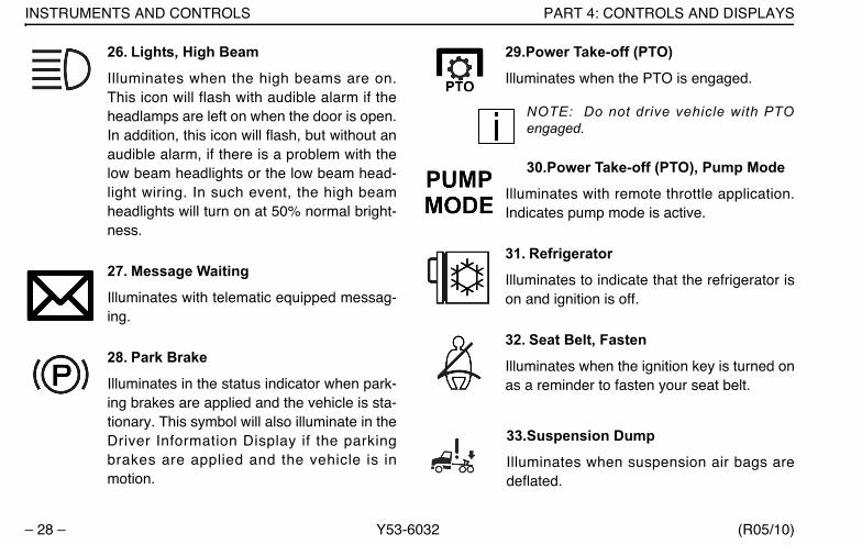
26. Lights, High Beam
Illuminates when the high beams are on.This icon will flash with audible alarm if theheadlamps are left on when the door is open.In addition, this icon will flash, but without anaudible alarm, if there is a problem with thelow beam headlights or the low beam head-light wiring. In such event, the high beamheadlights will turn on at 50% normal bright-ness.
27. Message Waiting
Illuminates with telematic equipped messag-ing.
28. Park Brake
Illuminates in the status indicator when park-ing brakes are applied and the vehicle is sta-tionary. This symbol will also illuminate in theDriver Information Display if the parkingbrakes are applied and the vehicle is inmotion.
29.Power Take-off (PTO)
Illuminates when the PTO is engaged.
NOTE: Do not drive vehicle with PTOengaged.
30.Power Take-off (PTO), Pump Mode
Illuminates with remote throttle application.Indicates pump mode is active.
31. Refrigerator
Illuminates to indicate that the refrigerator ison and ignition is off.
32. Seat Belt, Fasten
Illuminates when the ignition key is turned onas a reminder to fasten your seat belt.
33.Suspension Dump
Illuminates when suspension air bags aredeflated.
Y53-6032.book Page 28 Monday, May 24, 2010 3:37 PM

PART 4: CONTROLS AND DISPLAYS INSTRUMENTS AND CONTROLS
(R05/10) Y53-6032 – 29 –
34. Tire Inflation
Illuminates when tire pressures need to bechecked. (Tire Pressure Monitoring Systemis an option)
35. Transmission, Auxiliary
Illuminates to indicate auxiliary transmissionis in neutral.
36. Transmission, Check
Illuminates when transmission has recordeda fault code. This icon may also appear in theTransmission Display menu of the DriverInformation Display unit (see item G; page33). If the user is in this display menu, theicon does not indicate a fault code.
37. Transmission, Do Not Shift
Illuminates with automatic transmissionsequipped with “Don’t Shift” output.
38. Transmission, Oil Filter
Illuminates when service is required (Allisontransmissions only).
39. Transmission, Oil Temperature High
Illuminates when transmission lubricant tem-perature is too high.
CAUTION: This should be considered anemergency. You should stop the vehicle assafely as possible and turn OFF the ignition.The vehicle must be serviced and the prob-lem corrected before driving again. Failure todo so may cause severe transmission dam-age.
40. Turn Signal, Left
Blinks when the left turn signal or the hazardlight function is operating.
41. Turn Signal, Right
Blinks when the right turn signal or the haz-ard light function is operating.
Y53-6032.book Page 29 Monday, May 24, 2010 3:37 PM
DRIVER INFORMATION DISPLAY PART 4: CONTROLS AND DISPLAYS
– 30 – Y53-6032 (R05/10)
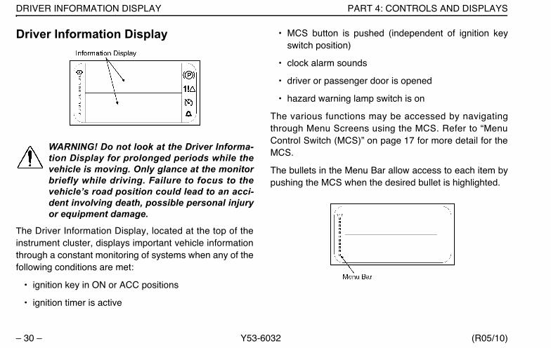
Driver Information Display
WARNING! Do not look at the Driver Informa-tion Display for prolonged periods while thevehicle is moving. Only glance at the monitorbriefly while driving. Failure to focus to thevehicle’s road position could lead to an acci-dent involving death, possible personal injuryor equipment damage.
The Driver Information Display, located at the top of theinstrument cluster, displays important vehicle informationthrough a constant monitoring of systems when any of thefollowing conditions are met:
• ignition key in ON or ACC positions
• ignition timer is active
• MCS button is pushed (independent of ignition keyswitch position)
• clock alarm sounds
• driver or passenger door is opened
• hazard warning lamp switch is on
The various functions may be accessed by navigatingthrough Menu Screens using the MCS. Refer to “MenuControl Switch (MCS)” on page 17 for more detail for theMCS.
The bullets in the Menu Bar allow access to each item bypushing the MCS when the desired bullet is highlighted.
Y53-6032.book Page 30 Monday, May 24, 2010 3:37 PM

PART 4: CONTROLS AND DISPLAYS DRIVER INFORMATION DISPLAY
(R05/10) Y53-6032 – 31 –
In addition to a blank screen, the following are menu itemsand the information available within each menu selec-tions.
NOTE: Some Driver Information Display functions areonly accessible when the vehicle is parked. Otherfunctions are accessible while the vehicle is movingor when parked. Each function is identified in the fol-lowing descriptions.
A. Fuel Economy (Accessible while parked or driving)
1. Current fuel economy - Indicates instantaneousfuel economy.
2. Trip fuel economy - Indicates trip fuel economy.
B. RPM Detail (Accessible while parked or driving)
RPM reading of actual engine RPM. Engine RPMwithin the bar graph indicates the engine is operat-ing in the most efficient RPM range. The displaycolor will change if you are operating outside of thisrange.
C. Ignition Timer (Accessible while parked only)
Ignition timer is set from this menu. The ignitiontimer may be set for up to 30 minutes.
Y53-6032.book Page 31 Monday, May 24, 2010 3:37 PM
DRIVER INFORMATION DISPLAY PART 4: CONTROLS AND DISPLAYS
– 32 – Y53-6032 (R05/10)
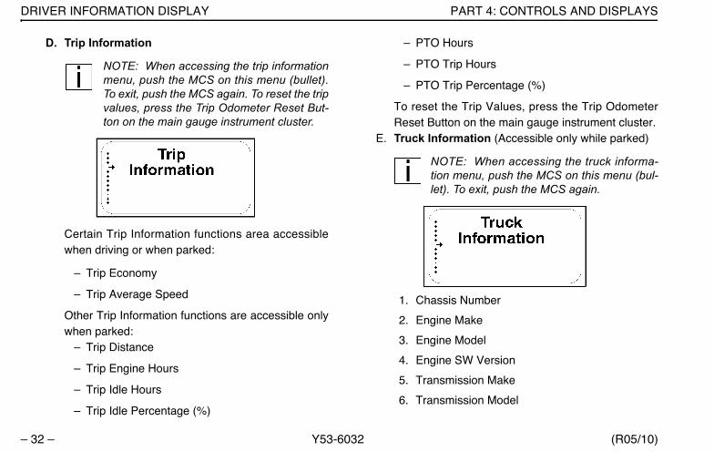
D. Trip Information
NOTE: When accessing the trip informationmenu, push the MCS on this menu (bullet).To exit, push the MCS again. To reset the tripvalues, press the Trip Odometer Reset But-ton on the main gauge instrument cluster.
Certain Trip Information functions area accessiblewhen driving or when parked:
– Trip Economy
– Trip Average Speed
Other Trip Information functions are accessible onlywhen parked:
– Trip Distance
– Trip Engine Hours
– Trip Idle Hours
– Trip Idle Percentage (%)
– PTO Hours
– PTO Trip Hours
– PTO Trip Percentage (%)
To reset the Trip Values, press the Trip OdometerReset Button on the main gauge instrument cluster.
E. Truck Information (Accessible only while parked)
NOTE: When accessing the truck informa-tion menu, push the MCS on this menu (bul-let). To exit, push the MCS again.
1. Chassis Number
2. Engine Make
3. Engine Model
4. Engine SW Version
5. Transmission Make
6. Transmission Model
Y53-6032.book Page 32 Monday, May 24, 2010 3:37 PM

PART 4: CONTROLS AND DISPLAYS DRIVER INFORMATION DISPLAY
(R05/10) Y53-6032 – 33 –
7. Transmission SW Version
8. ABS (Antilock Braking System) Make
9. ABS Model
10. ABS SW Version
11. CECU (Cab Electronic Control Unit) SoftwareVersion
12. CECU Hardware Version
F. Diagnostic Display (Accessible only while parked)
NOTE: “Faults Found” will only be active if ared or yellow warning lamp is illuminated.
The diagnostic display menu (bullet) will indicate afault that is generated by the vehicle's Engine, ABSand/or Transmission systems. While on this menuitem the display will either indicate "No Faults
Found" or "Faults Found". If "Faults Found" is active,pushing the MCS will display new menus for moreinformation.
G. Transmission Display (Automated Transmissionsonly - Accessible while parked or driving)
NOTE: Refer to the Automated TransmissionOperator’s Manual for additional information.
This menu will show gear number that coincides withthe current transmission gear selected. The menualso displays the transmission icon to let the userknow what screen they are in. (Does not indicate afault code.)
H. Settings Menu (Accessible only while parked)
The Settings menu screen allows the driver to viewand/or change the following menu items:
Y53-6032.book Page 33 Monday, May 24, 2010 3:37 PM

DRIVER INFORMATION DISPLAY PART 4: CONTROLS AND DISPLAYS
– 34 – Y53-6032 (R05/10)
• Display Format 12 Hour (AM/PM) or 24 Hour(military)
• Home/Local Time
• Alarm ON/OFF
• Alarm Time
• Units of measure
• Language (English, Spanish or French)
To Set Clock Display Format:
1. When in the Settings Menu, scroll through thelist of menu items to "Format".
2. Press the MCS to display either 12 hour (AM/PM) or 24 hour (military) time.
To Set Home, Local or Alarm Time:
1. When in the Settings Menu, scroll through thelist of menu items. Press the MCS to select theitem to change.
2.
3. Rotate the MCS knob to change the hour. Pressthe MCS.
Y53-6032.book Page 34 Monday, May 24, 2010 3:37 PM
PART 4: CONTROLS AND DISPLAYS STEERING COLUMN-MOUNTED CONTROLS
(R05/10) Y53-6032 – 35 –
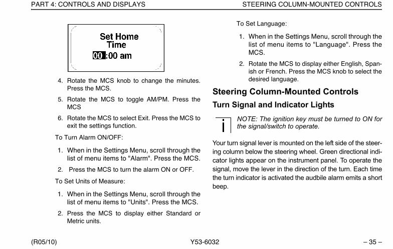
4. Rotate the MCS knob to change the minutes.Press the MCS.
5. Rotate the MCS to toggle AM/PM. Press theMCS
6. Rotate the MCS to select Exit. Press the MCS toexit the settings function.
To Turn Alarm ON/OFF:
1. When in the Settings Menu, scroll through thelist of menu items to "Alarm". Press the MCS.
2. Press the MCS to turn the alarm ON or OFF.
To Set Units of Measure:
1. When in the Settings Menu, scroll through thelist of menu items to "Units". Press the MCS.
2. Press the MCS to display either Standard orMetric units.
To Set Language:
1. When in the Settings Menu, scroll through thelist of menu items to "Language". Press theMCS.
2. Rotate the MCS to display either English, Span-ish or French. Press the MCS knob to select thedesired language.
Steering Column-Mounted ControlsTurn Signal and Indicator Lights
NOTE: The ignition key must be turned to ON forthe signal/switch to operate.
Your turn signal lever is mounted on the left side of the steer-ing column below the steering wheel. Green directional indi-cator lights appear on the instrument panel. To operate thesignal, move the lever in the direction of the turn. Each timethe turn indicator is activated the audbile alarm emits a shortbeep.
Y53-6032.book Page 35 Monday, May 24, 2010 3:37 PM
STEERING COLUMN-MOUNTED CONTROLS PART 4: CONTROLS AND DISPLAYS
– 36 – Y53-6032 (R05/10)
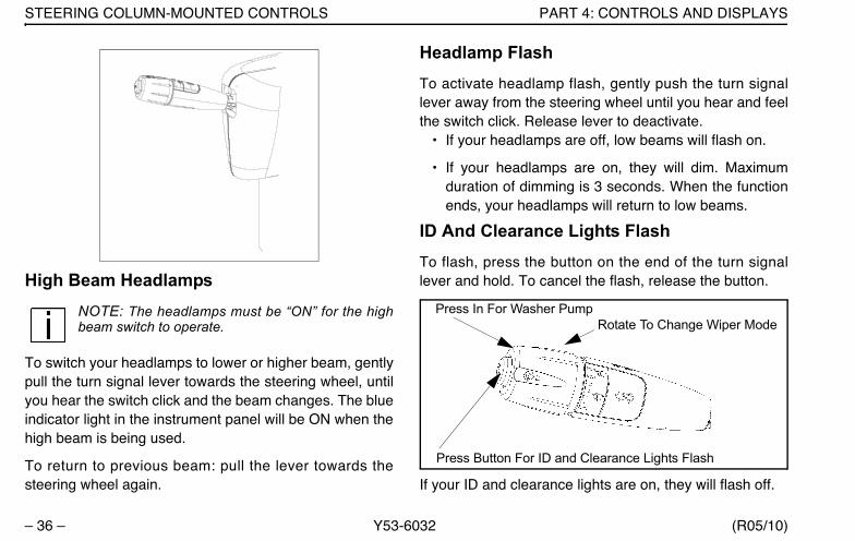
High Beam HeadlampsNOTE: The headlamps must be “ON” for the highbeam switch to operate.
To switch your headlamps to lower or higher beam, gentlypull the turn signal lever towards the steering wheel, untilyou hear the switch click and the beam changes. The blueindicator light in the instrument panel will be ON when thehigh beam is being used.
To return to previous beam: pull the lever towards thesteering wheel again.
Headlamp FlashTo activate headlamp flash, gently push the turn signallever away from the steering wheel until you hear and feelthe switch click. Release lever to deactivate.
• If your headlamps are off, low beams will flash on.
• If your headlamps are on, they will dim. Maximumduration of dimming is 3 seconds. When the functionends, your headlamps will return to low beams.
ID And Clearance Lights FlashTo flash, press the button on the end of the turn signallever and hold. To cancel the flash, release the button.
If your ID and clearance lights are on, they will flash off.
Press Button For ID and Clearance Lights Flash
Press In For Washer PumpRotate To Change Wiper Mode
Y53-6032.book Page 36 Monday, May 24, 2010 3:37 PM
PART 4: CONTROLS AND DISPLAYS STEERING COLUMN-MOUNTED CONTROLS
(R05/10) Y53-6032 – 37 –
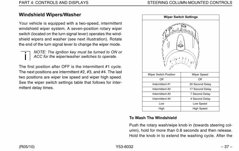
Windshield Wipers/WasherYour vehicle is equipped with a two-speed, intermittentwindshield wiper system. A seven-position rotary wiperswitch (located on the turn signal lever) operates the wind-shield wipers and washer (see next illustration). Rotatethe end of the turn signal lever to change the wiper mode.
NOTE: The ignition key must be turned to ON orACC for the wiper/washer switches to operate.
The first position after OFF is the intermittent #1 cycle.The next positions are intermittent #2, #3, and #4. The lasttwo positions are wiper low speed and wiper high speed.See the wiper switch settings table that follows for inter-mittent delay times.
To Wash The Windshield
Push the rotary wash/wipe knob in (towards steering col-umn), hold for more than 0.8 seconds and then release.Hold the knob in to extend the washing cycle. After the
Wiper Switch Settings
Wiper Switch Position Wiper Speed
Off Off
Intermittent #1 20 Second Delay
Intermittent #2 17 Second Delay
Intermittent #3 7 Second Delay
Intermittent #4 4 Second Delay
Low Low Speed
High High Speed
Y53-6032.book Page 37 Monday, May 24, 2010 3:37 PM
STEERING COLUMN-MOUNTED CONTROLS PART 4: CONTROLS AND DISPLAYS
– 38 – Y53-6032 (R05/10)
lever is released, the wipers will shut off automatically orresume the wiper’s setting speed.
To activate the wipers for one swipe without activating thewasher (“mist” function), push the turn signal lever in(towards the steering column) and release in less than 0.5seconds. The wipers will perform a single swipe and thenresume the wiper’s setting speed.
WARNING! Clean blades regularly with adamp cloth to remove road film and wax build-up. Do not drive with worn or dirty wiperblades. They can reduce visibility, makingdriving hazardous which may lead to an injuryaccident resulting in death or personal injury.
CAUTION:
• Do not use antifreeze or engine coolant inthe windshield washer reservoir—damage toseals and other components will result.
• If the electric pump is operated for a longperiod (more than 15 seconds) with a dry res-ervoir, the pump motor may be damaged.
Check the windshield washing fluid level daily. If neces-sary, fill to top.
Clean all inside and outside windows regularly. Use analcohol-based cleaning solution and wipe dry with either alint-free or a chamois cloth. Avoid running the wiperblades over a dry windshield to prevent scratching theglass. Spray on washer fluid first. A scratched windshieldwill reduce visibility.
Y53-6032.book Page 38 Monday, May 24, 2010 3:37 PM
PART 4: CONTROLS AND DISPLAYS STEERING COLUMN-MOUNTED CONTROLS
(R05/10) Y53-6032 – 39 –
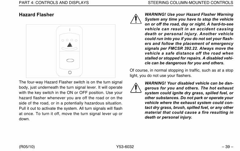
Hazard Flasher
The four-way Hazard Flasher switch is on the turn signalbody, just underneath the turn signal lever. It will operatewith the key switch in the ON or OFF position. Use yourhazard flasher whenever you are off the road or on theside of the road, or in a potentially hazardous situation.Pull it out to activate the system. All turn signals will flashat once. To turn it off, move the turn signal lever up ordown.
WARNING! Use your Hazard Flasher WarningSystem any time you have to stop the vehicleon or off the road, day or night. A hard-to-seevehicle can result in an accident causingdeath or personal injury. Another vehiclecould run into you if you do not set your flash-ers and follow the placement of emergencysignals per FMCSR 392.22. Always move thevehicle a safe distance off the road whenstalled or stopped for repairs. A disabled vehi-cle can be dangerous for you and others.
Of course, in normal stopping in traffic, such as at a stoplight, you do not use your flashers.
WARNING! Your disabled vehicle can be dan-gerous for you and others. The hot exhaustsystem could ignite dry grass, spilled fuel, orother substances. Do not park or operate yourvehicle where the exhaust system could con-tact dry grass, brush, spilled fuel, or any othermaterial that could cause a fire resulting indeath or personal injury.
Y53-6032.book Page 39 Monday, May 24, 2010 3:37 PM
STEERING COLUMN-MOUNTED CONTROLS PART 4: CONTROLS AND DISPLAYS
– 40 – Y53-6032 (R05/10)
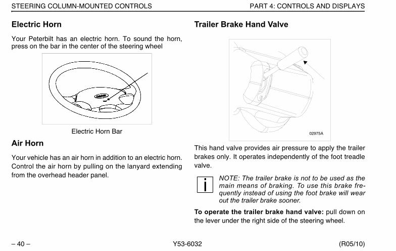
Electric HornYour Peterbilt has an electric horn. To sound the horn,press on the bar in the center of the steering wheel
Electric Horn Bar
Air HornYour vehicle has an air horn in addition to an electric horn.Control the air horn by pulling on the lanyard extendingfrom the overhead header panel.
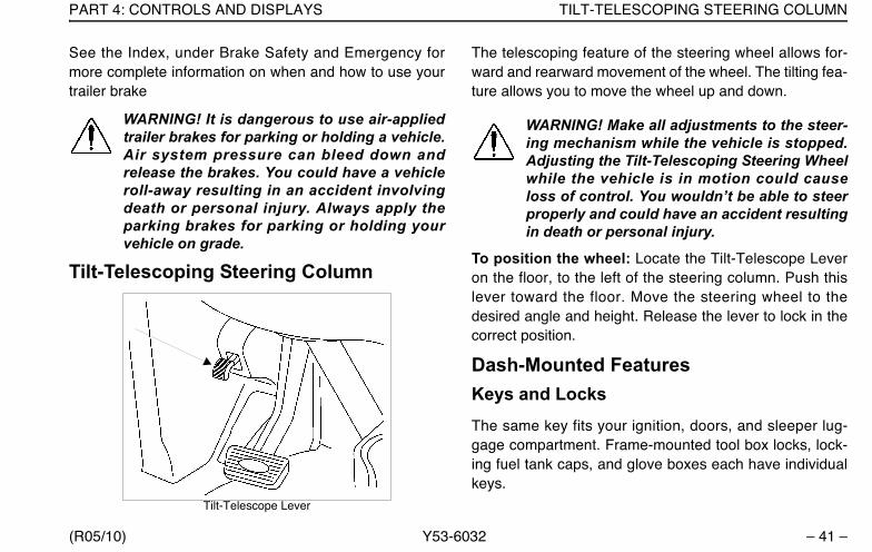
Trailer Brake Hand Valve
This hand valve provides air pressure to apply the trailerbrakes only. It operates independently of the foot treadlevalve.
NOTE: The trailer brake is not to be used as themain means of braking. To use this brake fre-quently instead of using the foot brake will wearout the trailer brake sooner.
To operate the trailer brake hand valve: pull down onthe lever under the right side of the steering wheel.
02975A
Y53-6032.book Page 40 Monday, May 24, 2010 3:37 PM
PART 4: CONTROLS AND DISPLAYS TILT-TELESCOPING STEERING COLUMN
(R05/10) Y53-6032 – 41 –
See the Index, under Brake Safety and Emergency formore complete information on when and how to use yourtrailer brake
WARNING! It is dangerous to use air-appliedtrailer brakes for parking or holding a vehicle.Air system pressure can bleed down andrelease the brakes. You could have a vehicleroll-away resulting in an accident involvingdeath or personal injury. Always apply theparking brakes for parking or holding yourvehicle on grade.
Tilt-Telescoping Steering Column
Tilt-Telescope Lever
The telescoping feature of the steering wheel allows for-ward and rearward movement of the wheel. The tilting fea-ture allows you to move the wheel up and down.
WARNING! Make all adjustments to the steer-ing mechanism while the vehicle is stopped.Adjusting the Tilt-Telescoping Steering Wheelwhile the vehicle is in motion could causeloss of control. You wouldn’t be able to steerproperly and could have an accident resultingin death or personal injury.
To position the wheel: Locate the Tilt-Telescope Leveron the floor, to the left of the steering column. Push thislever toward the floor. Move the steering wheel to thedesired angle and height. Release the lever to lock in thecorrect position.
Dash-Mounted FeaturesKeys and LocksThe same key fits your ignition, doors, and sleeper lug-gage compartment. Frame-mounted tool box locks, lock-ing fuel tank caps, and glove boxes each have individualkeys.
Y53-6032.book Page 41 Monday, May 24, 2010 3:37 PM

DASH-MOUNTED FEATURES PART 4: CONTROLS AND DISPLAYS
– 42 – Y53-6032 (R05/10)
Ignition Switch
Your ignition switch has four positions:
• ACC (Accessory): With your key in this position youcan play the radio or use other accessories, but yourengine won’t start.
• OFF: In this position all systems are off, and you canremove your key.
• IGN & ACC: This position allows you to turn on theengine and all accessory power.
• START: Starter activation to start engine.
HeadlampsThe headlamps are controlled by the control panel switchshowing the next symbol. When the headlights are ON,the dash lights, side, and tail lamps are also on.
WARNING! Do not use daytime running lights(DRL) during periods of darkness or reducedvisibility. Do not use DRL as a substitute forheadlamps or other lights during operationsthat require lighting of your vehicle. Doing socould lead to an accident involving death orpersonal injury.
On vehicles equipped with daytime running lights (DRL), thehigh-beam headlamps go on automatically at reduced
02977B
Y53-6032.book Page 42 Monday, May 24, 2010 3:37 PM
PART 4: CONTROLS AND DISPLAYS DASH-MOUNTED FEATURES
(R05/10) Y53-6032 – 43 –
brightness if the engine is running and the headlamp switchis turned off. The daytime running lights are turned off auto-matically while the parking brake is engaged. If the head-lamp switch is turned on, the DRL system is overridden &headlamps operate normally
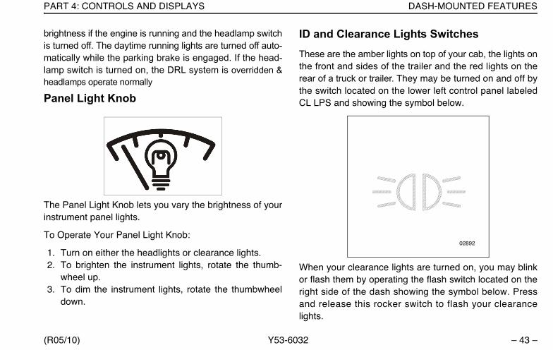
Panel Light Knob
The Panel Light Knob lets you vary the brightness of yourinstrument panel lights.
To Operate Your Panel Light Knob:
1. Turn on either the headlights or clearance lights.2. To brighten the instrument lights, rotate the thumb-
wheel up.3. To dim the instrument lights, rotate the thumbwheel
down.
ID and Clearance Lights SwitchesThese are the amber lights on top of your cab, the lights onthe front and sides of the trailer and the red lights on therear of a truck or trailer. They may be turned on and off bythe switch located on the lower left control panel labeledCL LPS and showing the symbol below.
When your clearance lights are turned on, you may blinkor flash them by operating the flash switch located on theright side of the dash showing the symbol below. Pressand release this rocker switch to flash your clearancelights.
02892
Y53-6032.book Page 43 Monday, May 24, 2010 3:37 PM

DASH-MOUNTED FEATURES PART 4: CONTROLS AND DISPLAYS
– 44 – Y53-6032 (R05/10)
Fog/ Driving Lights Switch
If your vehicle has fog/driving lights, turn them ON or OFFwith the control panel switch shown above.
NOTE: State requirements vary as to when highbeams and fog lights can and cannot be usedtogether. Further, some states allow only fourlights to be used together; some allow more.Whether you have dual or composite lights willaffect how many lights you can have on at onetime. Always comply with the state requirementswhere you are driving.
Dome Light Switch
A momentary switch controls the main dome light:
• OFF (O) Position: Light is off.
03912-1
0302102894A
I
O
Y53-6032.book Page 44 Monday, May 24, 2010 3:37 PM

PART 4: CONTROLS AND DISPLAYS DASH-MOUNTED FEATURES
(R05/10) Y53-6032 – 45 –
• ON (I) Position:
– Press once: Light will turn on at high intensity.
– Press again: Light will shift to low intensity.
– Press a third time: Light will turn off.
Air Suspension Deflate Switch (Dump Valve)
This vehicle may have an air suspension deflation switchthat allows the air in the suspension to be exhausted froma switch on the dash. The purpose of this feature is toallow you to lower your tractor to get under a trailer. You
will notice a guard over the switch. This prevents you fromaccidentally deflating the suspension.
WARNING! Operating the Air SuspensionDeflate Switch (Dump Valve) while driving canlead to an accident causing death or personalinjury. Sudden deflation while your vehicle ismoving can affect handling and control. Usethis switch only when your vehicle is not mov-ing.
CAUTION: Operating a vehicle with air suspen-sion bags either overinflated or underinflatedmay cause damage to driveline components. If avehicle must be operated under such condi-tions, do not exceed 5 mph.
03035
Y53-6032.book Page 45 Monday, May 24, 2010 3:37 PM
DASH-MOUNTED FEATURES PART 4: CONTROLS AND DISPLAYS
– 46 – Y53-6032 (R05/10)
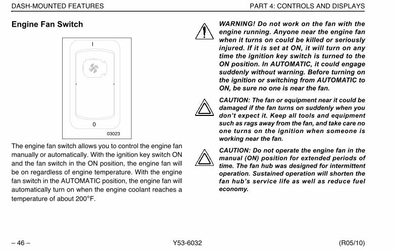
Engine Fan Switch
The engine fan switch allows you to control the engine fanmanually or automatically. With the ignition key switch ONand the fan switch in the ON position, the engine fan willbe on regardless of engine temperature. With the enginefan switch in the AUTOMATIC position, the engine fan willautomatically turn on when the engine coolant reaches atemperature of about 200°F.
WARNING! Do not work on the fan with theengine running. Anyone near the engine fanwhen it turns on could be killed or seriouslyinjured. If it is set at ON, it will turn on anytime the ignition key switch is turned to theON position. In AUTOMATIC, it could engagesuddenly without warning. Before turning onthe ignition or switching from AUTOMATIC toON, be sure no one is near the fan.
CAUTION: The fan or equipment near it could bedamaged if the fan turns on suddenly when youdon’t expect it. Keep all tools and equipmentsuch as rags away from the fan, and take care noone turns on the ignition when someone isworking near the fan.
CAUTION: Do not operate the engine fan in themanual (ON) position for extended periods oftime. The fan hub was designed for intermittentoperation. Sustained operation will shorten thefan hub’s service life as well as reduce fueleconomy.
I
003023
Y53-6032.book Page 46 Monday, May 24, 2010 3:37 PM

PART 4: CONTROLS AND DISPLAYS DASH-MOUNTED FEATURES
(R05/10) Y53-6032 – 47 –
Mirror Heat Switch
Mirror heat is controlled by the control panel switch shownabove. If the vehicle is equipped with this switch, mirrorheat can be switched on to help remove frost and ice fromthe mirror glass.
Power Mirror Switch
The power mirror control controls the adjustment of theright or left outside mirrors, depending on the optionselected. It is located in the driver side armrest.
NOTE: The Power Mirror Switch does not controlthe adjustment of the convex mirrors.
I
03022
O
Y53-6032.book Page 47 Monday, May 24, 2010 3:37 PM

DASH-MOUNTED FEATURES PART 4: CONTROLS AND DISPLAYS
– 48 – Y53-6032 (R05/10)
WARNING! Convex mirrors can distort imagesand make objects appear smaller and fartheraway than they really are. You could have anaccident resulting in death or personal injury ifyou are too close to another vehicle or otherobject. Keep plenty of space between yourvehicle and others when you turn or changelanes. Remember that other objects are closerthan they may appear.
Cruise Control Switch
The master switch turns the cruise control ON or OFF.The second switch allows you to SET the desired speed
or RESET the desired speed after the cruise control hasbeen interrupted.
WARNING! Do not operate the cruise controlwhen operating on road surfaces with poortraction (wet, icy, or snow covered roads) or inheavy traffic. Accelerations caused by thenormal operation of the cruise control couldcause you to lose control of the vehicle result-ing in an accident causing death or personalinjury.
NOTE: Cruise control functions and features mayvary depending upon which engine you have. Forspecific explanation of your cruise control, seethe cruise control or engine manual included withyour vehicle.
This vehilcle’s electronic system will perform a ‘rationalitycheck’ every time the vehicle is started. This check is toensure that the service brakes are working before allow-ing cruise control to function. This safety feature isdesigned to ensure that a driver is able to cancel thecruise set speed by using the service brake pedal. Thesystem will not allow cruise control operation if it does notpass the ‘rationality check’. The Driver Information Display
Y53-6032.book Page 48 Monday, May 24, 2010 3:37 PM

PART 4: CONTROLS AND DISPLAYS DASH-MOUNTED FEATURES
(R05/10) Y53-6032 – 49 –
will prompt you to press the service brake pedal if it hasnot been pressed since the vehicle has been started.
Engine Brake
When an engine brake is energized, the power-producingdiesel engine is converted into a power-absorbing aircompressor to retard the vehicle.
• The brake is energized whenever the driver’s foot iscompletely removed from the accelerator pedal.
• The brake is deenergized during driving by pressureon the accelerator pedal, and during shifting bydepressing the clutch pedal.
The ON/OFF toggle switch turns the system ON or OFF.
• In PACCAR, Caterpillar- and Cummins-powered vehi-cles equipped with a Jacobs Engine Brake, a secondtwo- or three-mode switch is incorporated in theinstrument panel. With this system, you can selecteither LOW or HIGH or LOW/MEDIUM/HIGH retard-ing.
For more information on when and how to use the enginebrake in your vehicle, see the Engine owner’s manual forthe engine brake.
Y53-6032.book Page 49 Monday, May 24, 2010 3:37 PM
DASH-MOUNTED FEATURES PART 4: CONTROLS AND DISPLAYS
– 50 – Y53-6032 (R05/10)
WARNING! Using the engine brake whenoperating on surfaces with poor traction(such as wet or icy, slippery roads or gravel)could cause an accident involving death orpersonal injury.
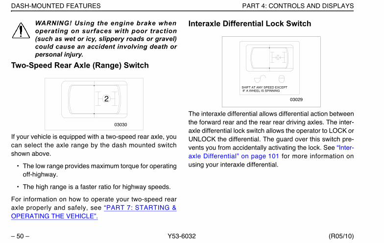
Two-Speed Rear Axle (Range) Switch
If your vehicle is equipped with a two-speed rear axle, youcan select the axle range by the dash mounted switchshown above.
• The low range provides maximum torque for operatingoff-highway.
• The high range is a faster ratio for highway speeds.
For information on how to operate your two-speed rearaxle properly and safely, see “PART 7: STARTING &OPERATING THE VEHICLE”.
Interaxle Differential Lock Switch
The interaxle differential allows differential action betweenthe forward rear and the rear rear driving axles. The inter-axle differential lock switch allows the operator to LOCK orUNLOCK the differential. The guard over this switch pre-vents you from accidentally activating the lock. See “Inter-axle Differential” on page 101 for more information onusing your interaxle differential.
03030
2
SHIFT AT ANY SPEED EXCEPT IF A WHEEL IS SPINNING
03029
Y53-6032.book Page 50 Monday, May 24, 2010 3:37 PM

PART 4: CONTROLS AND DISPLAYS DASH-MOUNTED FEATURES
(R05/10) Y53-6032 – 51 –
WARNING! Do not engage the differential lockif the vehicle is moving or if the tires are slip-ping. Otherwise, the vehicle may move in anunexpected direction, and could cause anaccident involving death or personal injury.This may also lead to equipment damage.Bring the vehicle to a complete stop andensure that all wheels are not spinning beforeengaging the differential lock switch.
Regeneration SwitchIn order to meet EPA engine emission requirements, vehi-cles will have a either a two or three position switch to helpcontrol and maintain the exhaust Diesel Particulate Filter.Please refer to “Exhaust After-Treatment System” onpage 126 for more information about the emission controlsystem and how it affects normal operating procedures.
START
Depressing the button in the START direction for 4 to 8seconds will initiate a parked regeneration. Be sure torelease the button to ensure that the system will beginthe regerenation cycle.
CENTER (three position switch only)
Center is the normal position of the switch.
The center position will allow an automatic regenera-tion to occur.
STOP (three position switch only)
When STOP is pressed the system will not regenerateunder any conditions.
CAUTION: Do not leave the three position switchin the STOP position unless you need to cancelor stop regeneration. Leaving the switch in theSTOP position for extended periods of time willresult in increased soot levels in the DPF.
Two Position Three Position
Y53-6032.book Page 51 Monday, May 24, 2010 3:37 PM
DASH-MOUNTED FEATURES PART 4: CONTROLS AND DISPLAYS
– 52 – Y53-6032 (R05/10)
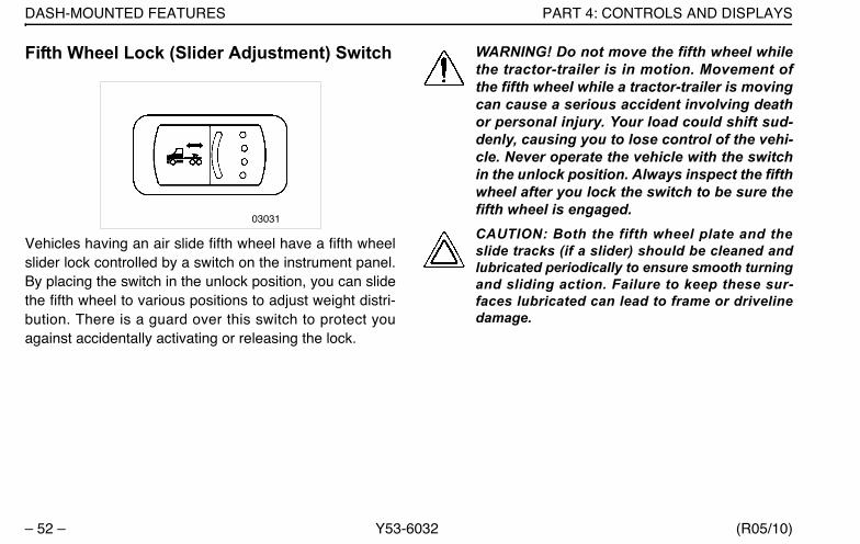
Fifth Wheel Lock (Slider Adjustment) Switch
Vehicles having an air slide fifth wheel have a fifth wheelslider lock controlled by a switch on the instrument panel.By placing the switch in the unlock position, you can slidethe fifth wheel to various positions to adjust weight distri-bution. There is a guard over this switch to protect youagainst accidentally activating or releasing the lock.
WARNING! Do not move the fifth wheel whilethe tractor-trailer is in motion. Movement ofthe fifth wheel while a tractor-trailer is movingcan cause a serious accident involving deathor personal injury. Your load could shift sud-denly, causing you to lose control of the vehi-cle. Never operate the vehicle with the switchin the unlock position. Always inspect the fifthwheel after you lock the switch to be sure thefifth wheel is engaged.CAUTION: Both the fifth wheel plate and theslide tracks (if a slider) should be cleaned andlubricated periodically to ensure smooth turningand sliding action. Failure to keep these sur-faces lubricated can lead to frame or drivelinedamage.
03031
Y53-6032.book Page 52 Monday, May 24, 2010 3:37 PM
PART 4: CONTROLS AND DISPLAYS DASH-MOUNTED FEATURES
(R05/10) Y53-6032 – 53 –
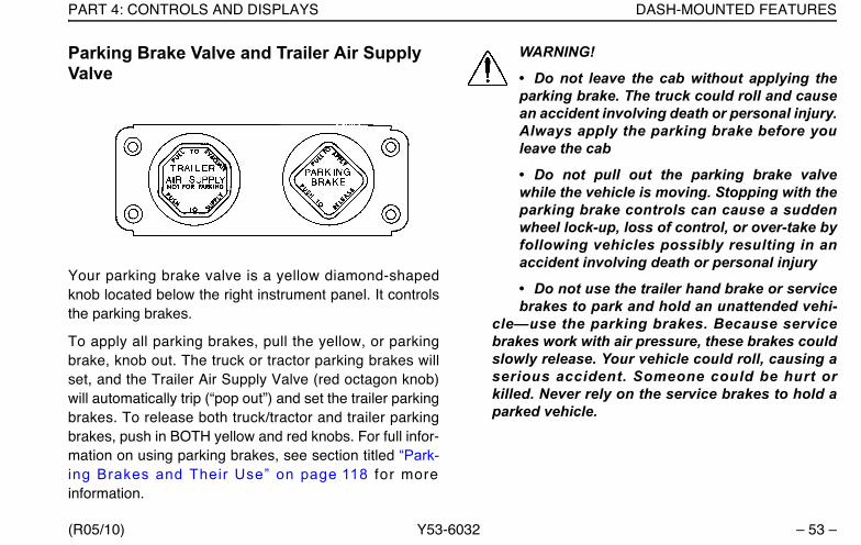
Parking Brake Valve and Trailer Air Supply Valve
Your parking brake valve is a yellow diamond-shapedknob located below the right instrument panel. It controlsthe parking brakes.
To apply all parking brakes, pull the yellow, or parkingbrake, knob out. The truck or tractor parking brakes willset, and the Trailer Air Supply Valve (red octagon knob)will automatically trip (“pop out”) and set the trailer parkingbrakes. To release both truck/tractor and trailer parkingbrakes, push in BOTH yellow and red knobs. For full infor-mation on using parking brakes, see section titled “Park-ing Brakes and Their Use” on page 118 for moreinformation.
WARNING!
• Do not leave the cab without applying theparking brake. The truck could roll and causean accident involving death or personal injury.Always apply the parking brake before youleave the cab
• Do not pull out the parking brake valvewhile the vehicle is moving. Stopping with theparking brake controls can cause a suddenwheel lock-up, loss of control, or over-take byfollowing vehicles possibly resulting in anaccident involving death or personal injury
• Do not use the trailer hand brake or servicebrakes to park and hold an unattended vehi-
cle—use the parking brakes. Because servicebrakes work with air pressure, these brakes couldslowly release. Your vehicle could roll, causing aserious accident. Someone could be hurt orkilled. Never rely on the service brakes to hold aparked vehicle.
Y53-6032.book Page 53 Monday, May 24, 2010 3:37 PM
DASH-MOUNTED FEATURES PART 4: CONTROLS AND DISPLAYS
– 54 – Y53-6032 (R05/10)
WARNING! Before operating your vehicle afterit has been parked, do not forget to push inthe parking brake valve to release the parkingbrakes. Failure to release your parking brakesbefore putting the vehicle into motion cancause fire or loss of control of the vehicle,which can result in death or personal injury.
Heater-Air Conditioning ControlsYour heat and air conditioning controls are mounted in theright hand instrument panel. Additionally, the sleeper com-partment may also contain a separate heating and coolingsystem with separate controls.
WARNING! Exhaust fumes from the enginecontain carbon monoxide, a colorless andodorless gas. Do not breathe the engineexhaust gas. A poorly maintained, damagedor corroded exhaust system can allow carbonmonoxide to enter the cab. Entry of carbonmonoxide into the cab is also possible fromother vehicles nearby. Failure to properlymaintain your vehicle could cause carbonmonoxide to enter the cab/sleeper and causedeath or serious illness.
WARNING! ever idle your vehicle for pro-longed periods of time if you sense thatexhaust fumes are entering the cab or sleeper.Investigate the cause of the fumes and correctit as soon as possible. If the vehicle must bedriven under these conditions, drive only withthe windows open. Failure to repair thesource of the exhaust fumes may lead todeath, injury or personal harm.
NOTES:Keep the engine exhaust system and thevehicle’s ventilation system properly maintained.It is recommended that the vehicle’s exhaust sys-tem and cab be inspected
•by a competent technician every 15,000 miles
•when a change is noticed in the sound of theexhaust system
•if the exhaust system, underbody, or cab is dam-aged
NOTE: To allow for proper operation of the vehicleventilation system, keep the inlet grille at the baseof the windshield clear of snow, ice, leaves andother obstructions at all times.
Y53-6032.book Page 54 Monday, May 24, 2010 3:37 PM
PART 4: CONTROLS AND DISPLAYS DASH-MOUNTED FEATURES
(R05/10) Y53-6032 – 55 –
NOTE: Do not stay in the vehicle with the enginerunning or idling for more than 10 minutes withthe vehicle’s Heater / AC ventilation system inRECIRC or at LOW FAN SPEED. Even with theventilation system On, running the engine whileparked or stopped for prolonged periods of time isnot recommended.
NOTE: If you are required to idle your vehicle forlong periods of time, install an auxiliary heater orautomatic idle control. These auxiliary devicescan reduce fuel consumption and save youmoney.
NOTES:When idling for short periods of time
•Set the heating or cooling system to Heat orA/C
•Set the fan to Medium or High speed
•Set the controls to FRESH AIR
NOTE: If other vehicles are parked next to youidling, move your vehicle or do not stay in yourvehicle for prolonged periods of time.
To Set the Heater-Air Conditioning Controls
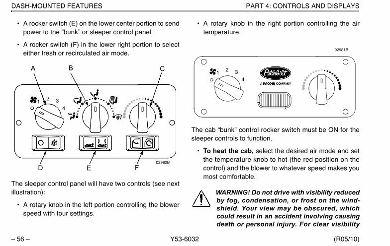
The cab’s control panel may have up to six controls (seeillustration below):
• A rotary knob (A) in the upper left portion controllingthe blower speed with four settings.
• A rotary knob (B) in the upper center portion control-ling the movement of air within the cab. This control iscontinuously variable through five modes (clockwisefrom left):
– Panel
– Panel/Floor
– Floor
– Defrost/Floor
– Defrost
• A rotary knob (C) in the upper right portion controllingthe air temperature.
• A rocker switch (D) in the lower left portion to engagethe air conditioner compressor.
Y53-6032.book Page 55 Monday, May 24, 2010 3:37 PM
DASH-MOUNTED FEATURES PART 4: CONTROLS AND DISPLAYS
– 56 – Y53-6032 (R05/10)
• A rocker switch (E) on the lower center portion to sendpower to the “bunk” or sleeper control panel.
• A rocker switch (F) in the lower right portion to selecteither fresh or recirculated air mode.
The sleeper control panel will have two controls (see nextillustration):
• A rotary knob in the left portion controlling the blowerspeed with four settings.
• A rotary knob in the right portion controlling the airtemperature.
The cab “bunk” control rocker switch must be ON for thesleeper controls to function.
• To heat the cab, select the desired air mode and setthe temperature knob to hot (the red position on thecontrol) and the blower to whatever speed makes youmost comfortable.
WARNING! Do not drive with visibility reducedby fog, condensation, or frost on the wind-shield. Your view may be obscured, whichcould result in an accident involving causingdeath or personal injury. For clear visibility
02980B
4
A B C
D E F
321
02981B
4321
Y53-6032.book Page 56 Monday, May 24, 2010 3:37 PM
PART 4: CONTROLS AND DISPLAYS DASH-MOUNTED FEATURES
(R05/10) Y53-6032 – 57 –
and safe driving, it is extremely important foryou to follow the instructions pertaining tothe function and use of the ventilation/heatingand defogging/defrosting system. If in doubt,consult your dealer. Maximum heating outputand fast defrosting can be obtained only afterthe engine has reached operating tempera-ture.
CAUTION: During extreme cold weather, do notblow hot defroster air onto cold windshields.This could crack the glass. Turn the air flow con-trol lever to Defrost and adjust the fan speedaccordingly while the engine warms. If theengine is already warm, move the temperatureselector to Cool, then gradually increase thetemperature when you see that the windshield isstarting to warm up.
• To defog the windshield, select the Defrost modeand turn the blower speed to high. Set the tempera-ture knob to hot (the red position on the control). Theair conditioner is automatically activated to removemoisture from the cab. After the windshield is clear,adjust the mode, blower speed, and temperature toyour comfort.
• To cool the cab, turn on the A/C switch, set the tem-perature knob to cool (the blue position on the con-trol), and the blower to high until the cab becomescool. Then you can turn down the blower if you wish.
For Efficient Cooling:
1. Be sure all heater - air conditioner controls are off.2. Start the engine. Allow time for warm-up.
CAUTION:
• A cold compressor can cause refrigerant toliquefy and warp the valve plates or cause ahydraulic lock. Warm the engine before start-ing the air conditioner.
• Turn off all controls when the system is notin use. Doing so will avoid damage to the airconditioning system components.
3. Set the air control in the RECIRC mode.4. Close all windows.5. Idle the engine between 1000 and 1500 RPM and
turn the blower speed control to high.6. After the cab temperature cools to a comfortable level,
adjust the blower speed and controls to keep thedesired condition.
Y53-6032.book Page 57 Monday, May 24, 2010 3:37 PM
DASH-MOUNTED FEATURES PART 4: CONTROLS AND DISPLAYS
– 58 – Y53-6032 (R05/10)
NOTE: When the air conditioner isn’t in regularuse, operate it for at least 15 minutes at leastonce a month or every 5,000 miles(8,000 Km),whichever comes first. This will lubricate the sealsin the air conditioning system. The air condition-ing system is active when the Defrost mode isselected.
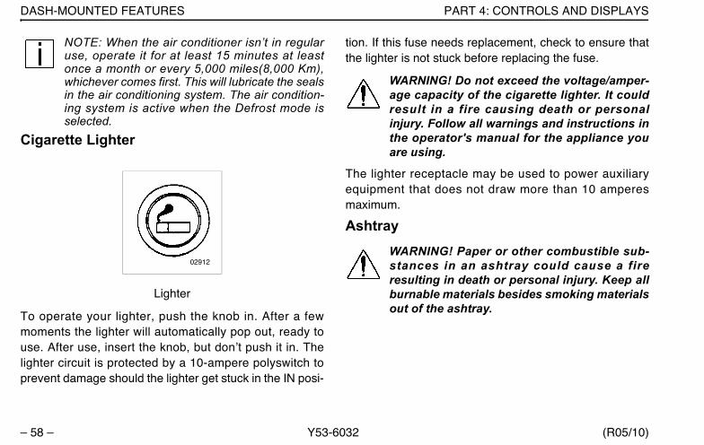
Cigarette Lighter
Lighter
To operate your lighter, push the knob in. After a fewmoments the lighter will automatically pop out, ready touse. After use, insert the knob, but don’t push it in. Thelighter circuit is protected by a 10-ampere polyswitch toprevent damage should the lighter get stuck in the IN posi-
tion. If this fuse needs replacement, check to ensure thatthe lighter is not stuck before replacing the fuse.
WARNING! Do not exceed the voltage/amper-age capacity of the cigarette lighter. It couldresult in a fire causing death or personalinjury. Follow all warnings and instructions inthe operator's manual for the appliance youare using.
The lighter receptacle may be used to power auxiliaryequipment that does not draw more than 10 amperesmaximum.
AshtrayWARNING! Paper or other combustible sub-stances in an ashtray could cause a fireresulting in death or personal injury. Keep allburnable materials besides smoking materialsout of the ashtray.
02912
Y53-6032.book Page 58 Monday, May 24, 2010 3:37 PM
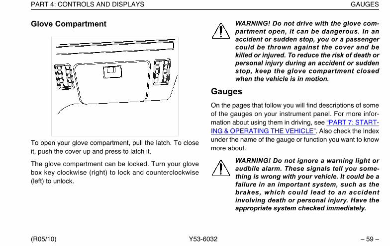
PART 4: CONTROLS AND DISPLAYS GAUGES
(R05/10) Y53-6032 – 59 –
Glove Compartment
To open your glove compartment, pull the latch. To closeit, push the cover up and press to latch it.
The glove compartment can be locked. Turn your glovebox key clockwise (right) to lock and counterclockwise(left) to unlock.
WARNING! Do not drive with the glove com-partment open, it can be dangerous. In anaccident or sudden stop, you or a passengercould be thrown against the cover and bekilled or injured. To reduce the risk of death orpersonal injury during an accident or suddenstop, keep the glove compartment closedwhen the vehicle is in motion.
GaugesOn the pages that follow you will find descriptions of someof the gauges on your instrument panel. For more infor-mation about using them in driving, see “PART 7: START-ING & OPERATING THE VEHICLE”. Also check the Indexunder the name of the gauge or function you want to knowmore about.
WARNING! Do not ignore a warning light oraudbile alarm. These signals tell you some-thing is wrong with your vehicle. It could be afailure in an important system, such as thebrakes, which could lead to an accidentinvolving death or personal injury. Have theappropriate system checked immediately.
Y53-6032.book Page 59 Monday, May 24, 2010 3:37 PM
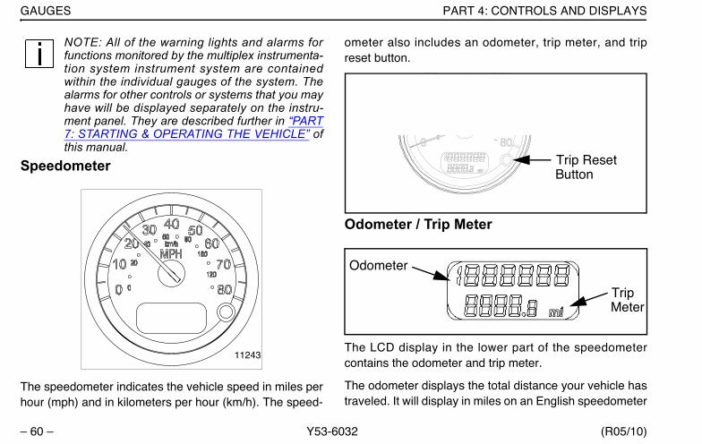
GAUGES PART 4: CONTROLS AND DISPLAYS
– 60 – Y53-6032 (R05/10)
NOTE: All of the warning lights and alarms forfunctions monitored by the multiplex instrumenta-tion system instrument system are containedwithin the individual gauges of the system. Thealarms for other controls or systems that you mayhave will be displayed separately on the instru-ment panel. They are described further in “PART7: STARTING & OPERATING THE VEHICLE” ofthis manual.
Speedometer
The speedometer indicates the vehicle speed in miles perhour (mph) and in kilometers per hour (km/h). The speed-
ometer also includes an odometer, trip meter, and tripreset button.
Odometer / Trip Meter
The LCD display in the lower part of the speedometercontains the odometer and trip meter.
The odometer displays the total distance your vehicle hastraveled. It will display in miles on an English speedometer
11243
Trip ResetButton
Odometer
TripMeter
Y53-6032.book Page 60 Monday, May 24, 2010 3:37 PM

PART 4: CONTROLS AND DISPLAYS GAUGES
(R05/10) Y53-6032 – 61 –
or in kilometers on a metric speedometer. The maximumdistance that can be shown on the odometer is “1 999 999” before it rolls over to zero.
The trip odometer displays how far the vehicle has goneon a particular trip. The trip odometer will display in mileson an English speedometer or in kilometers on a metricspeedometer, in one tenth divisions. The maximum dis-tance that can be shown on the trip odometer is “9999.9”before it rolls over to zero.
To reset the trip odometer, press and hold the trip resetbutton on the speedometer. The numbers will reset to 0and begin to count new miles/km traveled. This alsoresets the trip values in the Driver Information Display.
The trip reset button also toggles all displays betweenEnglish and Metric. (See page 62.)
NOTE: The Odometer/Trip Meter comes on whenthe door is opened or the key is in the accessoryor ignition position. The Odometer/Trip Meter willremain on for 3 seconds after the door is closedor the ignition switch is turned off. This allowsdriver and service personnel to read the odome-ter without ignition switch being turned on.
Tachometer
Your tachometer measures the engine speed in revolu-tions-per-minute (RPM). The tachometer also includes anengine hour meter and outside air temperature display.
Watching your tachometer is important to driving effi-ciently. It will let you match driving speed and gear selec-tion to the operating range of your engine. If your enginespeed gets too high, you can select a higher gear to lowerthe RPM. If your engine speed drops too low, you canselect a lower gear to raise the RPM.
11244
Y53-6032.book Page 61 Monday, May 24, 2010 3:37 PM
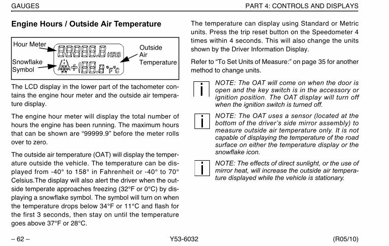
GAUGES PART 4: CONTROLS AND DISPLAYS
– 62 – Y53-6032 (R05/10)
Engine Hours / Outside Air Temperature
The LCD display in the lower part of the tachometer con-tains the engine hour meter and the outside air tempera-ture display.
The engine hour meter will display the total number ofhours the engine has been running. The maximum hoursthat can be shown are “99999.9” before the meter rollsover to zero.
The outside air temperature (OAT) will display the temper-ature outside the vehicle. The temperature can be dis-played from -40° to 158° in Fahrenheit or -40° to 70°Celsius.The display will also alert the driver when the out-side temperate approaches freezing (32°F or 0°C) by dis-playing a snowflake symbol. The symbol will turn on whenthe temperature drops below 34°F or 11°C and flash forthe first 3 seconds, then stay on until the temperaturegoes above 37°F or 28°C.
The temperature can display using Standard or Metricunits. Press the trip reset button on the Speedometer 4times within 4 seconds. This will also change the unitsshown by the Driver Information Display.
Refer to “To Set Units of Measure:” on page 35 for anothermethod to change units.
NOTE: The OAT will come on when the door isopen and the key switch is in the accessory orignition position. The OAT display will turn offwhen the ignition switch is turned off.
NOTE: The OAT uses a sensor (located at thebottom of the driver’s side mirror assembly) tomeasure outside air temperature only. It is notcapable of displaying the temperature of the roadsurface on either the temperature display or thesnowflake icon.
NOTE: The effects of direct sunlight, or the use ofmirror heat, will increase the outside air tempera-ture displayed while the vehicle is stationary.
Hour Meter OutsideAirTemperatureSnowflake
Symbol
Y53-6032.book Page 62 Monday, May 24, 2010 3:37 PM
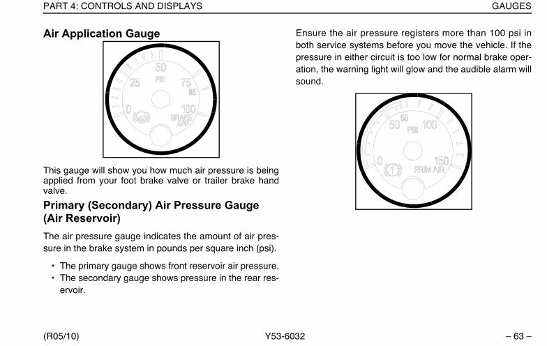
PART 4: CONTROLS AND DISPLAYS GAUGES
(R05/10) Y53-6032 – 63 –
Air Application Gauge
This gauge will show you how much air pressure is beingapplied from your foot brake valve or trailer brake handvalve.
Primary (Secondary) Air Pressure Gauge (Air Reservoir)The air pressure gauge indicates the amount of air pres-sure in the brake system in pounds per square inch (psi).
• The primary gauge shows front reservoir air pressure.• The secondary gauge shows pressure in the rear res-
ervoir.
Ensure the air pressure registers more than 100 psi inboth service systems before you move the vehicle. If thepressure in either circuit is too low for normal brake oper-ation, the warning light will glow and the audible alarm willsound.
Y53-6032.book Page 63 Monday, May 24, 2010 3:37 PM
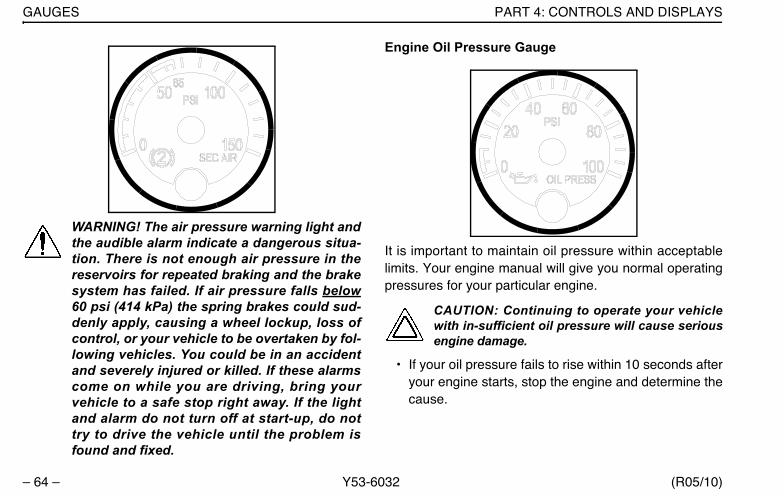
GAUGES PART 4: CONTROLS AND DISPLAYS
– 64 – Y53-6032 (R05/10)
WARNING! The air pressure warning light andthe audible alarm indicate a dangerous situa-tion. There is not enough air pressure in thereservoirs for repeated braking and the brakesystem has failed. If air pressure falls below60 psi (414 kPa) the spring brakes could sud-denly apply, causing a wheel lockup, loss ofcontrol, or your vehicle to be overtaken by fol-lowing vehicles. You could be in an accidentand severely injured or killed. If these alarmscome on while you are driving, bring yourvehicle to a safe stop right away. If the lightand alarm do not turn off at start-up, do nottry to drive the vehicle until the problem isfound and fixed.
Engine Oil Pressure Gauge
It is important to maintain oil pressure within acceptablelimits. Your engine manual will give you normal operatingpressures for your particular engine.
CAUTION: Continuing to operate your vehiclewith in-sufficient oil pressure will cause seriousengine damage.
• If your oil pressure fails to rise within 10 seconds afteryour engine starts, stop the engine and determine thecause.
Y53-6032.book Page 64 Monday, May 24, 2010 3:37 PM

PART 4: CONTROLS AND DISPLAYS GAUGES
(R05/10) Y53-6032 – 65 –
• If your oil pressure suddenly drops while you are driv-ing, bring the vehicle to a stop as soon as possible ina safe location off the road and turn off the engine.Wait a few minutes to allow oil to drain into the oil pan,and then check the oil level. Add oil if necessary. If theproblem persists, contact an authorized service cen-ter.
Water Temperature Gauge
The water temperature gauge shows the temperature ofthe engine coolant. Under normal operating conditions thewater temperature gauge should register between 165°and 205°F (74° and 90°C). Under certain conditions,somewhat higher temperatures may be acceptable. But
the maximum allowable temperature is 210°F (99°C) withthe cooling system pressurized, except for certain specialengines. Check your engine manual to be sure.
Engine Overheating
WARNING! Do not remove the radiator fill capwhile the engine is hot. Scalding steam andfluid under pressure may escape and causedeath or personal injuries.
• Wait until the coolant temperature is below122°F (50°C).
• Protect face, hands, and arms by coveringthe cap with a large, thick rag to protectagainst escaping fluid and steam.
• Carefully and slowly turn the cap one-quar-ter of a turn or until it reaches the first stop(allowing excess pressure to escape) pushdown and turn for final removal.
Wait until the coolant temperature is below 122° F (50° C).Protect your face, hands, and arms by covering the capwith a large, thick rag to protect you against escaping fluidand steam. Before you completely remove the cap, care-fully and slowly turn the cap part way to allow excess
Y53-6032.book Page 65 Monday, May 24, 2010 3:37 PM

GAUGES PART 4: CONTROLS AND DISPLAYS
– 66 – Y53-6032 (R05/10)
pressure to escape. Then push down and turn for finalremoval.
The cooling system may overheat if the coolant level isbelow normal or if there is a sudden loss of coolant (suchas a worn hose splitting). It may also temporarily overheatduring severe operating conditions such as climbing along hill on a hot day or stopping after high-speed driving.
If the “Engine Coolant Temperature” warning light comeson, or you have any other reason to suspect the enginemay be overheating:
• Stop the vehicle, but DON’T TURN OFF THEENGINE unless a low water warning device indicatesa loss of coolant.
• With the transmission in neutral, check to be certainthe oil pressure gauge reads normal. Increase theengine speed to about 1100 - 1200 RPM, maximum.Return the idle speed to normal after 2 or 3 minutes. Ifthe warning light doesn’t go off or the temperaturegauge doesn’t begin to drop, then turn the engine off.
If the overheating came from severe operating conditions,the temperature should have cooled by this time. If it has
not, stop the engine and let it cool before checking to seeif the coolant is low.
Fuel Gauge
WARNING! Do not remove a fuel tank cap nearan open flame. Fuel vapors are combustibleand can cause an explosion or fire resulting ininjury or death.
WARNING! Do not breathe diesel fumes asexposure to diesel fumes may cause respira-tory illness, personal injury or death.
Y53-6032.book Page 66 Monday, May 24, 2010 3:37 PM
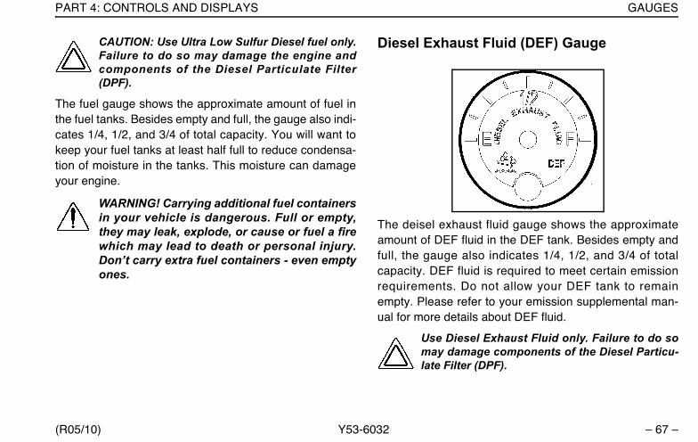
PART 4: CONTROLS AND DISPLAYS GAUGES
(R05/10) Y53-6032 – 67 –
CAUTION: Use Ultra Low Sulfur Diesel fuel only.Failure to do so may damage the engine andcomponents of the Diesel Particulate Filter(DPF).
The fuel gauge shows the approximate amount of fuel inthe fuel tanks. Besides empty and full, the gauge also indi-cates 1/4, 1/2, and 3/4 of total capacity. You will want tokeep your fuel tanks at least half full to reduce condensa-tion of moisture in the tanks. This moisture can damageyour engine.
WARNING! Carrying additional fuel containersin your vehicle is dangerous. Full or empty,they may leak, explode, or cause or fuel a firewhich may lead to death or personal injury.Don’t carry extra fuel containers - even emptyones.
Diesel Exhaust Fluid (DEF) Gauge
The deisel exhaust fluid gauge shows the approximateamount of DEF fluid in the DEF tank. Besides empty andfull, the gauge also indicates 1/4, 1/2, and 3/4 of totalcapacity. DEF fluid is required to meet certain emissionrequirements. Do not allow your DEF tank to remainempty. Please refer to your emission supplemental man-ual for more details about DEF fluid.
Use Diesel Exhaust Fluid only. Failure to do somay damage components of the Diesel Particu-late Filter (DPF).
Y53-6032.book Page 67 Monday, May 24, 2010 3:37 PM
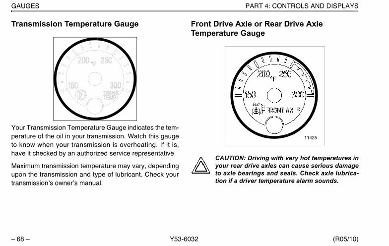
GAUGES PART 4: CONTROLS AND DISPLAYS
– 68 – Y53-6032 (R05/10)
Transmission Temperature Gauge
Your Transmission Temperature Gauge indicates the tem-perature of the oil in your transmission. Watch this gaugeto know when your transmission is overheating. If it is,have it checked by an authorized service representative.
Maximum transmission temperature may vary, dependingupon the transmission and type of lubricant. Check yourtransmission’s owner’s manual.
Front Drive Axle or Rear Drive Axle Temperature Gauge
CAUTION: Driving with very hot temperatures inyour rear drive axles can cause serious damageto axle bearings and seals. Check axle lubrica-tion if a driver temperature alarm sounds.
11425
Y53-6032.book Page 68 Monday, May 24, 2010 3:37 PM

PART 4: CONTROLS AND DISPLAYS GAUGES
(R05/10) Y53-6032 – 69 –
These gauges indicate the temperature of the lubricant inyour vehicle’s axle(s). These temperatures will vary withthe kind of load you are carrying and the driving condi-tions you encounter. Maximum axle temperature mayvary, depending upon the axle and type of lubricant. Veryhigh temperatures signal a need to have your axle(s)’lubrication checked.
Manifold Pressure Gauge
Your manifold pressure gauge indicates the power yourengine is putting out by showing the amount of turboboost. If the pressure indicated by your manifold pressuregauge goes down, there may be something wrong withyour engine. Have it checked by a qualified service per-son.
11425a
Y53-6032.book Page 69 Monday, May 24, 2010 3:37 PM

GAUGES PART 4: CONTROLS AND DISPLAYS
– 70 – Y53-6032 (R05/10)
Voltmeter
The voltmeter displays the voltage at which your batteriesare being charged while the engine is operating.
NOTE: Even with a healthy charge/start system,the voltmeter may fall well below 12V duringengine cranking. If voltage drops below 12V andstays there, have the electrical system checked.
Air Filter Restriction Indicator Gauge
This gauge indicates the condition of the engine aircleaner and is measured by inches of water (H2O). Aclean filter should register 7 in. H2O (may vary with sys-tem design) and a filter whose life is over will registerapproximately 25 in. H2O.
Y53-6032.book Page 70 Monday, May 24, 2010 3:37 PM

PART 4: CONTROLS AND DISPLAYS GAUGES
(R05/10) Y53-6032 – 71 –
CAUTION: Continued operation with the Air Fil-ter Re-striction Gauge reading 25” H2O maycause damage to the engine. Inspect the filterand replace if necessary. Holes in the paper ele-ment render an air cleaner useless and maycause the Air Filter Restriction Gauge to give afalse reading, even if the element is clogged.Replace the element if it is damaged.
Shift Pattern DisplayThe correct shift pattern for your vehicle appears on yourcontrol panel, windshield or on a medallion in the shiftknob. It is important that you know more about your trans-mission than just the shift pattern. Please read the manu-facturer’s manual that is included with your vehicle.
MirrorsWARNING! Convex mirrors can distort imagesand make objects appear smaller and fartheraway than they really are. You could have anaccident resulting in death or personal injury ifyou are too close to another vehicle or otherobject. Keep plenty of space between yourvehicle and others when you turn or changelanes. Remember that other objects are closerthan they may appear.
Your vehicle is equipped with outside mirrors to enableyou to see to the sides and behind your vehicle. Be surethey are adjusted properly before you drive off. You willhave the best field of view to the side if you adjust eachmirror so you can just see the side of your vehicle in theinboard part of the mirror.
Luggage Compartment(s)An interior luggage compartment is under the bunk in thesleeper. The exterior compartment is beneath the bunk,opening from the driver’s side, on the outside of the cab.
WARNING! Carrying objects loose in your cabor sleeper can be dangerous. In a suddenstop, or even going over a bump, th objectcould fly forward and strike you or a passen-ger, possibly causing death or serious injury.Secure loose objects. Carry any heavyobjects in the exterior luggage compartmentand close it securely.
WARNING! Do not store combustible materi-als in the luggage compartment. They mayleak and, if ignited, cause or fuel a fire whichmay lead to death or personal injury.
Y53-6032.book Page 71 Monday, May 24, 2010 3:37 PM
GAUGES PART 4: CONTROLS AND DISPLAYS
– 72 – Y53-6032 (R05/10)
Appliances in the CabYou may decide to equip your vehicle with a radio, a refrig-erator, or other appliances and conveniences. Be surethey are compatible with your truck’s electrical system.Secure them in the cab so they can’t fly loose in a suddenstop.
WARNING! In a sudden stop or collision aheavy object in your cab could strike you oranyone with you. You could be injured orkilled. Secure any appliance (such as a refrig-erator or radio) you add to your cab.
Refrigerator
Follow the procedure below to operate the refrigerator.
CAUTION: Leaving your refrigerator on when thevehicle’s engine is not running will rapidly rundown your vehicle’s batteries. This may causepremature battery failure.
NOTES:
•For additional information about the refrigerator,refer to the refrigerator owner’s manual that camewith this appliance.
•Refrigerator cooling ability decreases as sleepertemperature increases.
The main power supply to the refrigerator and cooling fan(located behind the refrigerator) is controlled by a switchlabeled "REFRIG/FAN" located on the sleeper controlpanel.
• To turn the refrigerator and cooling fan on, move theREFRIG/FAN switch to ON, then turn the thermostatdial (located inside the refrigerator) clockwise fromthe OFF setting.
• To turn the refrigerator and cooling fan off, turn thethermostat dial inside the refrigerator counterclock-wise to the OFF setting, then move the REFRIG/FANswitch to OFF.
• To turn only the refrigerator off, turn the thermostatdial counterclockwise to OFF.
Y53-6032.book Page 72 Monday, May 24, 2010 3:37 PM

PART 4: CONTROLS AND DISPLAYS GAUGES
(R05/10) Y53-6032 – 73 –
Peterbilt Navigation SystemYour vehicle may be equipped with a Peterbilt NavigationSystem. This system is a Global Positioning Satellite(GPS)-linked computer. It receives input from multiplesources to locate your vehicle. Read and understand theSupplemental Navigation System Owner’s Manual andobserve the Warnings, Cautions, and Notes that followbefore using the system.
WARNING! Verify legal weight and heightrestrictions for the route suggested by theNavigation System. Failure to verify heightrestrictions could lead to death or personalinjury. Failure to verify weight restrictionscould also result in a traffic infraction.
WARNING! Only glance at the NavigationSystem monitor while driving. Prolonged peri-ods of viewing while driving could result in anaccident and death or possible personalinjury.
WARNING! Do not program the NavigationSystem while driving. Always stop your vehi-cle when programming or changing the set-tings on the Navigation System. Programmingthe system while driving can cause you totake your eyes off the road, which could resultin an accident. Failure to do so could lead todeath, serious injury or equipment damage.
CAUTION: Do not rely on the Navigation Systemto route you to the closest emergency services.Not all emergency services are in the database.
NOTE: Regardless of how and where the naviga-tion system directs you, it is your responsibility tooperate the vehicle in a safe and legal manner.
NOTE: Ensure the volume level of all audiodevices is set to a level that still allows you to hearoutside traffic and emergency vehicles.
Y53-6032.book Page 73 Monday, May 24, 2010 3:37 PM
GAUGES PART 4: CONTROLS AND DISPLAYS
– 74 – Y53-6032 (R05/10)
NOTE: The map database is the most currentavailable at the time of production. The databaseis designed to provide you with route suggestionsand does not take into account the relative safetyof a suggested route or of factors that may affectthe time required to reach your destination. Seethe Supplemental Navigation System Owner’sManual for more information.
Y53-6032.book Page 74 Monday, May 24, 2010 3:37 PM
PART 5: SEAT AND RESTRAINT SYSTEMS SEAT
(R05/10) Y53-6032 – 75 –
PART 5: SEAT AND RESTRAINT SYSTEMS
SeatFor information on the features and adjustment of theseat, see the seat manufacturer’s literature included withthe vehicle.
WARNING! Do not drive or ride with your seatback in the reclined position. You could beinjured or killed by sliding under the seatbelts in a collision.
WARNING! Do not adjust the driver's seatwhile the vehicle is moving. A sudden orunexpected seat movement can cause thedriver to lose control of the vehicle causingdeath or personal injury. Make all adjustmentsto the seat while the vehicle is stopped.
• After adjusting the seat and before drivingoff, always check to be sure that the seat isfirmly latched in position.
Seat Belts And Their Proper UseSeat (or safety) belts have proven to be the single mosteffective means available for reducing the risk of seriousinjury and death in motor vehicle accidents. It’s not just anopinion -- it’s a fact: Seat belts save lives.
WARNING! Do not drive vehicle without yourseat belt and your riders’ belts fastened.Riding without a safety belt which is properlyfastened can lead to increased death or injuryin an accident. Unbelted riders could bethrown into the windshield or other parts ofthe cab or could be thrown out of the cab.They could strike another person. Injuries canbe much worse when riders are unbelted.Always fasten your seat belt and be sure any-one riding with you does the same.
Y53-6032.book Page 75 Monday, May 24, 2010 3:37 PM

SEAT BELTS AND THEIR PROPER USE PART 5: SEAT AND RESTRAINT SYSTEMS
– 76 – Y53-6032 (R05/10)
Person In Crash, Unbelted
Shoulder BeltYour combination shoulder-lap belt needs proper adjust-ment:
• The lap portion should be worn as low on the hips aspossible
Properly worn belt
02998
Y53-6032.book Page 76 Monday, May 24, 2010 3:37 PM

PART 5: SEAT AND RESTRAINT SYSTEMS SEAT BELTS AND THEIR PROPER USE
(R05/10) Y53-6032 – 77 –
Improperly worn belt
The shoulder portion should fit snugly across your body. Itshould always be worn over the shoulder next to the door.It you put the belt under your arm, it can’t protect youproperly
WARNING! Always wear your seat belt lowover your pelvic bones.
• You can be killed or seriously injured if yourbelt is buckled too high. In a crash, it wouldapply force to your abdomen, not your pel-vic bones. This can result in death or seri-ous internal injuries.
.
Correct (over arm)
Y53-6032.book Page 77 Monday, May 24, 2010 3:37 PM
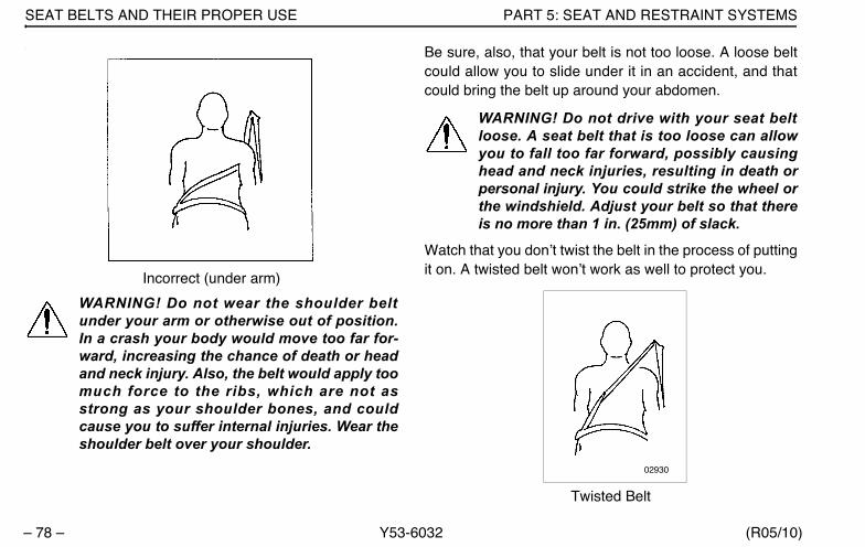
SEAT BELTS AND THEIR PROPER USE PART 5: SEAT AND RESTRAINT SYSTEMS
– 78 – Y53-6032 (R05/10)
.
Incorrect (under arm)
WARNING! Do not wear the shoulder beltunder your arm or otherwise out of position.In a crash your body would move too far for-ward, increasing the chance of death or headand neck injury. Also, the belt would apply toomuch force to the ribs, which are not asstrong as your shoulder bones, and couldcause you to suffer internal injuries. Wear theshoulder belt over your shoulder.
Be sure, also, that your belt is not too loose. A loose beltcould allow you to slide under it in an accident, and thatcould bring the belt up around your abdomen.
WARNING! Do not drive with your seat beltloose. A seat belt that is too loose can allowyou to fall too far forward, possibly causinghead and neck injuries, resulting in death orpersonal injury. You could strike the wheel orthe windshield. Adjust your belt so that thereis no more than 1 in. (25mm) of slack.
Watch that you don’t twist the belt in the process of puttingit on. A twisted belt won’t work as well to protect you.
Twisted Belt
02930
Y53-6032.book Page 78 Monday, May 24, 2010 3:37 PM
PART 5: SEAT AND RESTRAINT SYSTEMS SEAT BELTS AND THEIR PROPER USE
(R05/10) Y53-6032 – 79 –
WARNING! Do not twist the belt in the processof putting it on. A twisted belt will not work aswell to protect you. In a crash, the full width ofthe belt would not be protecting you. Atwisted belt could cut into your body andcause death or serious injuries. Straighten thebelt before buckling it. If you are unable towear it without twisting it, have your dealer orservice person repair it as soon as possible
To connect your shoulder-lap belt: Grasp the belttongue and pull in a smooth, slow motion across yourchest and lap. Insert the tongue into the buckle on theinboard side of the seat. Push down until you hear a click.Pull on the belt to make sure it is buckled. Check that it ispositioned correctly on your body.
Komfort-Lok® FeatureYour Peterbilt contains a feature designed to eliminatecinching and provide improved safety and comfort. Cinch-ing is the condition where a belt becomes continuallytighter around you during a rough, bouncy ride. The needfor this feature increases with rough road conditions, par-ticularly over long distances.
To eliminate cinching simply activate the comfort featureat the appropriate time:
1. Fasten your seat belt according to the directions.
2. You are now ready to activate the Komfort-Lok. Leanforward to pull a little slack (about 1 inch) in the belt.Be sure to allow only a small amount of slack. See theWarning on a loose belt, on the previous page.
3. When the slack is right, slide the comfort feature upWhen the slack is right, flip the latch cover up, cinch-ing it into place. This locks the Komfort-Lok.
4. To release the Komfort-Lok latch, reach up and pullthe latch cover open (down), or simply pull down onthe shoulder belt.
5. When you want to get out of the cab, release thelatch, then just push the button on the buckle.
Pregnant Women: Sometimes pregnant women worrythat in a crash the seat belt could hurt the baby. But if awoman wears her belt properly - low over her pelvis,below her abdomen - the belt won’t harm the baby, even ina crash. And remember - the best way to keep an unbornbaby safe is to keep the mother safe.
Y53-6032.book Page 79 Monday, May 24, 2010 3:37 PM
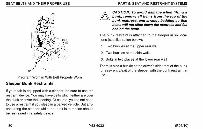
SEAT BELTS AND THEIR PROPER USE PART 5: SEAT AND RESTRAINT SYSTEMS
– 80 – Y53-6032 (R05/10)
.
Pregnant Woman With Belt Properly Worn
Sleeper Bunk RestraintsIf your cab is equipped with a sleeper, be sure to use therestraint device. You may have belts which either are overthe bunk or cover the opening. Of course, you do not needto use a restraint if you sleep in a parked vehicle. But any-one using the sleeper while the truck is in motion shouldbe restrained in a safety device.
CAUTION: To avoid damage when lifting abunk, remove all items from the top of thebunk mattress, and arrange bedding so thatitems will not slide down the mattress and fallbehind the bunk.
The bunk restraint is attached to the sleeper in six loca-tions (see illustration below):
1. Two buckles at the upper rear wall
2. Two buckles at the side walls
3. Bolts in two places at the lower rear wall
There is also a buckle at the driver’s side front of the bunkfor easy entry/exit of the sleeper with the bunk restraint inuse.
Y53-6032.book Page 80 Monday, May 24, 2010 3:37 PM

PART 5: SEAT AND RESTRAINT SYSTEMS SEAT BELTS AND THEIR PROPER USE
(R05/10) Y53-6032 – 81 –
• The upper rear wall: Access to the bunk is easiestwhen these connections are buckled and the frontbuckle is detached.
• The side walls: The tenting straps are attached to theside wall sills with easy-to-use buckles.
• The lower rear wall: The restraint is attached to thelower rear wall by bolts that do not require removal foruse or stowage of the bunk restraint.
You will notice that if your Peterbilt has an upper bunk, ithas no restraint device. This is because no one shouldever be in an upper bunk when the vehicle is moving.
WARNING!
• In an accident an unrestrained person lying ina sleeper bunk could be killed or seriouslyinjured. He or she could be thrown from thebunk. Be sure anyone occupying thesleeper is restrained while a vehicle is mov-ing.
• Be sure that no one ever rides in the upperbunk while the vehicle is in motion. Thatperson would be thrown out in an accidentand could be killed or seriously injured.
PassengersAnyone riding in your vehicle should wear a seat belt. Theresponsible operator sees to it that everyone in the vehiclerides safely - and that means with a seat belt.
Y53-6032.book Page 81 Monday, May 24, 2010 3:37 PM

SEAT BELTS AND THEIR PROPER USE PART 5: SEAT AND RESTRAINT SYSTEMS
– 82 – Y53-6032 (R05/10)
Some Other Safety Restraint Tips:• Don’t wear belts over rigid or breakable objects in or
on your clothing. Such things might be eyeglasses,pens, keys, etc. These could cause injury in an acci-dent.
• Damaged belts in the cab or sleeper must bereplaced. Belts that have been stretched, cut, or wornout may not protect you in an accident.
• Avoid catching belts in the doors or seat hardware.They could be damaged.
• Don’t modify or disassemble the seat belts in yourvehicle. They won’t be available to keep you and yourpassengers safe.
• Never bleach or dye seat belts; chemicals canweaken them. Do, however, keep them clean by fol-lowing the care label on the belts. Let them dry com-pletely before allowing them to retract.
• If any seat belt is not working properly, see an autho-rized Peterbilt dealer for repair or replacement.
Tether BeltsTether belts are installed on suspension seats. They helpsecure the seat to the floor to restrain it in case of a sud-den stop or an accident.
WARNING! Do not remove, modify, or replacethe tether belt system with a different tethersystem. A failed or missing tether belt couldallow the seat base to fully extend in the eventof an accident leading to greater injuries ordeath.
Y53-6032.book Page 82 Monday, May 24, 2010 3:37 PM
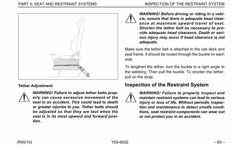
PART 5: SEAT AND RESTRAINT SYSTEMS INSPECTION OF THE RESTRAINT SYSTEM
(R05/10) Y53-6032 – 83 –
Tether Adjustment
WARNING! Failure to adjust tether belts prop-erly can cause excessive movement of theseat in an accident. This could lead to deathor greater injuries to you. Tether belts shouldbe adjusted so that they are taut when theseat is in its most upward and forward posi-tion.
WARNING! Before driving or riding in a vehi-cle, ensure that there is adequate head clear-ance at maximum upward travel of seat.Shorten the tether belt as necessary to pro-vide adequate head clearance. Death or seri-ous injury may occur if head clearance is notadequate.
Make sure the tether belt is attached to the cab deck andseat frame. It should be routed through the buckle on eachside.
To lengthen the tether, turn the buckle to a right angle tothe webbing. Then pull the buckle. To shorten the tether,pull on the strap.
Inspection of the Restraint SystemWARNING! Failure to properly inspect andmaintain restraint systems can lead to seriousinjury or loss of life. Without periodic inspec-tion and maintenance to detect unsafe condi-tions, seat restraint components can wear outor not protect you in an accident.
Y53-6032.book Page 83 Monday, May 24, 2010 3:37 PM

INSPECTION OF THE RESTRAINT SYSTEM PART 5: SEAT AND RESTRAINT SYSTEMS
– 84 – Y53-6032 (R05/10)
The typical three-point seat systems in passenger carsmay seem very similar to the three-point seat belt systemin heavy duty vehicles, but there are some key differencesthat all users of this system should be aware of:
• In typical passenger vehicle automotive seat beltapplications, the normal life of the vehicles is usually 8to 10 years and the total mileage frequently does notexceed 125,000 miles (200,000 km). Heavy duty vehi-cles often see this type of mileage in a very shortperiod of time, and accumulation of mileage in excessof 500,000 miles (800,000 km) during the vehicle life-time is not unusual.
• A significant difference in the two systems is theamount of movement of webbing in the system. In anautomotive application, there is little movement of theseat belt system, except when the user puts on ortakes off the belt. In trucks, however, there is almostconstant movement of the belt through hardware dueto ride characteristics and seats which are designedto move, in order to enhance driver comfort. Therecan even be movement of the webbing in the seat beltsystem when the belt in not being used. Relative
movement between the seat and the cab, which nor-mally occurs whenever the truck is in operation, cancause wear of the seat belt webbing.
• Environmental conditions represent another major dif-ference in the systems in automobiles and heavy dutyand specialty vehicles. Unlike the automotive environ-ment, heavy duty and specialty vehicles may be verydirty, and have more exposure to the sun’s damagingultraviolet rays, thus resulting in a reduction of the lifeof the seat belt system.
The high mileage associated with heavy duty vehicles andpossible wear of the 3-point seat belt system, the contin-ual relative movement of the system, the possible contactwith the vehicle seat or other parts of the cab structure,and the potential exposure of this system to severe envi-ronmental conditions make it crucial to inspect the three-point seat belt systems regularly.
It is recommended that the seat belt system in a vehiclebe inspected every 20,000 miles (32,000 km) or moreoften if the vehicle is exposed to severe environmentalconditions. Any seat belt system that shows cuts, fraying,extreme or unusual wear, significant discoloration due toUV exposure, abrasion to the seat belt webbing, or dam-
Y53-6032.book Page 84 Monday, May 24, 2010 3:37 PM
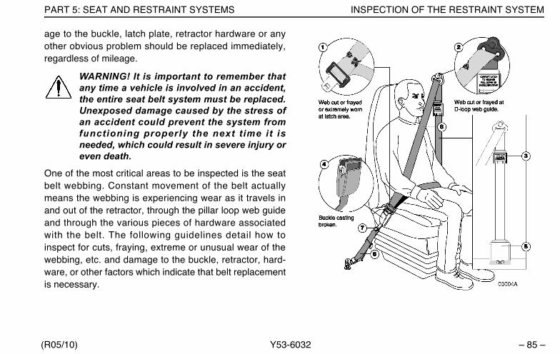
PART 5: SEAT AND RESTRAINT SYSTEMS INSPECTION OF THE RESTRAINT SYSTEM
(R05/10) Y53-6032 – 85 –
age to the buckle, latch plate, retractor hardware or anyother obvious problem should be replaced immediately,regardless of mileage.
WARNING! It is important to remember thatany time a vehicle is involved in an accident,the entire seat belt system must be replaced.Unexposed damage caused by the stress ofan accident could prevent the system fromfunctioning properly the next time it isneeded, which could result in severe injury oreven death.
One of the most critical areas to be inspected is the seatbelt webbing. Constant movement of the belt actuallymeans the webbing is experiencing wear as it travels inand out of the retractor, through the pillar loop web guideand through the various pieces of hardware associatedwith the belt. The following guidelines detail how toinspect for cuts, fraying, extreme or unusual wear of thewebbing, etc. and damage to the buckle, retractor, hard-ware, or other factors which indicate that belt replacementis necessary.
Y53-6032.book Page 85 Monday, May 24, 2010 3:37 PM
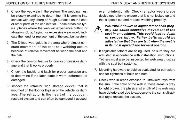
INSPECTION OF THE RESTRAINT SYSTEM PART 5: SEAT AND RESTRAINT SYSTEMS
– 86 – Y53-6032 (R05/10)
1. Check the web wear in the system. The webbing mustbe closely examined to determine if it is coming intocontact with any sharp or rough surfaces on the seator other parts of the cab interior. These areas are typ-ical places where the web will experience cutting orabrasion. Cuts, fraying, or excessive wear would indi-cate the need for replacement of the seat belt system.
2. The D-loop web guide is the area where almost con-stant movement of the seat belt webbing occursbecause of relative movement between the seat andthe cab.
3. Check the comfort feature for cracks or possible dam-age and that it works properly.
4. Check the buckle and latch for proper operation andto determine if the latch plate is worn, deformed, ordamaged.
5. Inspect the retractor web storage device, that ismounted on the floor or B-pillar of the vehicle for dam-age. The retractor is the heart of the occupantrestraint system and can often be damaged if abused,
even unintentionally. Check retractor web storagedevice operation to ensure that it is not locked up andthat it spools out and retracts webbing properly.
WARNING! Failure to adjust tether belts prop-erly can cause excessive movement of theseat in an accident. This could lead to deathor serious injury. Tether belts should beadjusted so that they are taut when the seat isin its most upward and forward position.
6. If adjustable tethers are being used, be sure they areadjusted in accordance with installation instructions.Tethers must also be inspected for web wear, just aswith the seat belt systems.
7. Mounting hardware should be evaluated for corrosion,and for tightness of bolts and nuts.
8. Check web in areas exposed to ultraviolet rays fromthe sun. If the color of the web in these areas is grayto light brown, the physical strength of this web mayhave deteriorated due to exposure to the sun’s ultravi-olet rays; replace the system.
Y53-6032.book Page 86 Monday, May 24, 2010 3:37 PM

PART 5: SEAT AND RESTRAINT SYSTEMS INSPECTION OF THE RESTRAINT SYSTEM
(R05/10) Y53-6032 – 87 –
WARNING! Replace the entire belt system(retractor and buckle side) if replacement ofany one part is necessary. Unexposed damageto one or more components could prevent thesystem from functioning properly the next timeit is needed, which could result in severe injuryor even death.
If the inspection indicates that any part of the seat beltsystem requires replacement, the entire system must bereplaced, both retractor and buckle side. An installationguide is attached to every replacement belt. This set ofinstructions is entitled “THREE-POINT SEAT BELTINSTALLATION GUIDE.” There are separate seat beltinstruction guides for suspension and fixed bench seats.Use the proper guide for your type of seat, and follow the
instructions very closely. It is vitally important that all com-ponents must be remounted back in the same position asthe original components that were removed. This willmaintain the design integrity of the mounting points for theseat belt assembly.
Once the need for replacement of the seat belt has beendetermined, be certain that it is only replaced with the rec-ommended replacement seat belt. The occupant restraintsystem has been developed and tested specifically for thisvehicle. If the vehicle was originally equipped with a lapbelt, it cannot be replaced with a three-point shoulder har-ness system, because the cab mounting points are notstructurally designed for a three-point seat belt.
Y53-6032.book Page 87 Monday, May 24, 2010 3:37 PM
SAFE VEHICLE OPERATION PART 6: DRIVER’S CHECKLIST
– 88 – Y53-6032 (R05/10)
PART 6: DRIVER’S CHECKLIST
Safe Vehicle OperationTo keep your vehicle in top shape, and to maintain its highlevel of safety for you, your passengers, and your load,make a thorough inspection every day before you drive.You’ll save maintenance time later -- and the safetychecks could help prevent a serious accident. Pleaseremember, too, that Federal law requires a pre-trip inspec-tion and so do commercial trucking companies.
For more information, you can refer to Federal Motor Car-rier Safety Regulation 392.7 which tells you that interstatecommercial motor vehicles are not to be driven unless thedriver is sure that certain parts and accessories are inworking order.
You aren’t expected to become a professional mechanic.The purpose of your inspections is to find anything thatmight interfere with the safe and efficient transportation of
yourself and your load. If you do find something wrongand can’t fix it yourself, please have a qualified mechanicfix it right away.
For your safety, as well as those around you, be a respon-sible driver:
• If you drink, do not drive.
• Do not drive if you are tired, ill, or under emotionalstress.
Much has gone into the manufacturing of your Peterbilt,including advanced engineering techniques, rigid qualitycontrol, and demanding inspections. These manufactur-ing processes will be enhanced by you—the safe driver—who observes the following:
• knows & understands how to operate a vehicle and allits controls
• maintains the vehicle properly
• uses driving skills wisely
Y53-6032.book Page 88 Monday, May 24, 2010 3:37 PM

PART 6: DRIVER’S CHECKLIST SAFE VEHICLE OPERATION
(R05/10) Y53-6032 – 89 –
WARNING! Do not drink and drive. Yourreflexes, perceptions, and judgment can beaffected by even a small amount of alcohol.You could have a serious—even fatal—acci-dent if you drive after drinking. Please do notdrink and drive or ride with a driver who’sbeen drinking.
• The use of alcohol, drugs, and certain med-ications will seriously impair perception,reactions, and driving ability. These circum-stances can substantially increase the riskof an accident and death or serious per-sonal injury.
The daily checks listed below are the foundation of youroverall preventive maintenance program. See “PART 8:MAINTENANCE AND SERVICE” for the complete preven-tive maintenance schedule for your vehicle.
Approaching the Vehicle1. Check the overall appearance and condition. Are win-
dows, mirrors, and lights clean and unobstructed?
2. Check beneath the vehicle. Are there signs of fuel, oil,or water leaks?
3. Check for damaged, loose, or missing parts. Are thereparts showing signs of excessive wear or lack of lubri-cation? Have a qualified mechanic examine any ques-tionable items and repair them without delay.
Checking Under the Hood or CabWith the engine stopped:
1. Check the engine oil level; top up as necessary. Refer toyour engine’s operating manual for the type of oil to use.
2. Check the engine coolant level while the engine iscold. Top up as necessary with premixed coolant.Refer to the instructions on page 193 for adding cool-ant to the proper level.
3. Check the engine belts. Refer to the instructions onpage 210 to check belt condition and adjust tension.
4. Check brake lines and hoses.
5. Check all other accessories, controls, belts, hoses,and wiring for condition and adjustment.
6. Check the windshield washer fluid level; top up asnecessary.
Y53-6032.book Page 89 Monday, May 24, 2010 3:37 PM

SAFE VEHICLE OPERATION PART 6: DRIVER’S CHECKLIST
– 90 – Y53-6032 (R05/10)
7. Check the power steering fluid reservoir; top up asnecessary.
8. Check the steering components (pitman arm, dra-glink, power steering hoses, etc.)
9. Drain the fuel/water separator.
Checking the Luggage Compartment1. Check the fire extinguisher charge.
2. Check the road emergency kit. Is it complete?
WARNING! Do not store combustible materi-als in the luggage compartment. They mayleak and, if ignited, cause or fuel a fire whichmay lead to death or personal injury.
Checking Outside the Vehicle1. Be sure all wheel studs and cap nuts are secure.
Check wheel cap nut torque weekly; refer to theinstructions on page 185.
2. Check tires for condition and proper inflation.
3. Check the front wheel bearing lube level.
4. Check parking (spring) brakes as to the condition andtightness of air lines, breathers, clamp rings & bolts,mounting studs, and release bolts.
5. Check turn signal operation.
6. Check emergency flashers and exterior lamps.
7. Check the fuel tanks. Is there enough fuel? Are thetank caps secure?
WARNING!
• Diesel fuel in the presence of an ignitionsource (such as a cigarette) could cause anexplosion. You could be killed or seriouslyinjured. A mixture of gasoline or alcoholwith diesel fuel increases this risk of explo-sion. Use only the fuel recommended foryour engine.
• Fuel vapors are combustible and can causean explosion or fire resulting in injury ordeath. Do not remove a fuel tank cap nearan open flame.
• Do not breathe diesel fumes as exposure todiesel fumes may cause respiratory illness,personal injury or death.
Y53-6032.book Page 90 Monday, May 24, 2010 3:37 PM

PART 6: DRIVER’S CHECKLIST SAFE VEHICLE OPERATION
(R05/10) Y53-6032 – 91 –
8. Visually inspect the fuel tank mounting hardware. Arethe tank straps tight? Is the webbing in place?
9. Check the air cleaner and exhaust system. Are theytight and secure?
10. Check the trailer connections. Are they secure andthe lines clear? If they are not being used, are theystored properly?
11. Is the trailer spare wheel secure? Inflated?
12. Is the landing gear up and the handle secured?
13. Check the 5th wheel. Is the kingpin locked?
14. Is the sliding 5th wheel locked?
15. Check for loose or missing suspension fasteners.
16. Check springs or other suspension parts for damagesuch as cracks, gouges, distortions, bulges, or chaf-ing.
17. Check the air system. Are there leaks?
18. Drain excess moisture from all air supply tanks. Makesure the drain valves are closed. This procedure isalso required for air supply tanks equipped with auto-matic drain valves.
In-Cab ChecklistWARNING! To avoid death or injury whileentering or leaving the cab, keep your feet incontact with the steps and your hands on thehandhold. Always have three points of con-tact as you enter or exit a cab. See “PART 2:GETTING INTO & OUT OF THE CAB ANDFRAME ACCESS” of this manual for moreinformation.
1. Adjust the seats.
2. Fasten and adjust safety restraint belts. See “PART 5:SEAT AND RESTRAINT SYSTEMS”, or the Index,under Restraint Systems.
3. Sleeper Restraints: Check and inspect condition. See“PART 5: SEAT AND RESTRAINT SYSTEMS”, or theIndex, under Restraint Systems.
4. Adjust the steering column.
Y53-6032.book Page 91 Monday, May 24, 2010 3:37 PM

SAFE VEHICLE OPERATION PART 6: DRIVER’S CHECKLIST
– 92 – Y53-6032 (R05/10)
5. Check mirror adjustment.
6. Operate air-powered devices to circulate lubricants.
NOTE: The above items should be checked daily,as a minimum. They are in addition to, not inplace of Federal Motor Carrier Safety Regula-tions. These may be purchased by writing to:
Superintendent of Documents
U.S. Government Printing Office
Washington, DC 20402
Y53-6032.book Page 92 Monday, May 24, 2010 3:37 PM

PART 7: STARTING & OPERATING THE VEHICLE NORMAL TEMPERATURE STARTING PROCEDURE
(05/10) Y53-6032 – 93 –
PART 7: STARTING & OPERATING THE VEHICLE
Since each vehicle is custom-equipped, all engine opera-tion instructions in this manual are general. You will wantto consult the manual for your engine to find out detailsabout your specific engine’s needs. You may need to usea slightly different procedure from the one outlined here.Below are instructions for both normal-temperature start-ing and cold-weather starting.
Normal Temperature Starting Procedure When the outside temperature is above 50° F (10° C), youcan use the following procedure.
1. Set the parking brake.
2. Put your main transmission in Neutral.
3. Disengage (depress) the clutch (with manual trans-mission).
4. Turn the key switch to ON.
• The driver information display will proceed throughthe instrumentation self test (refer to page 18 for adescription of the instrumentation self test).
NOTE: Refer to “Warning Light/Indicator SymbolDescriptions,” Page 23 if the Driver InformationDisplay other messages or if other alarms acti-vate after the key is turned ON.
5. Turn the key to start.
CAUTION: Never operate the starter motorwhile the engine is running. The starter andflywheel gears could clash or jam, severelydamaging them.
NOTE: Some starters are equipped with overcrankprotection. Check the “Engine Operation and Main-tenance Manual” for details.
If the engine does not start within 30 seconds, release thestarter button. To avoid overtaxing the starter motor or thebatteries, don’t use the starter for more than 30 seconds.Let the starter motor cool and the batteries recover for 2
Y53-6032.book Page 93 Monday, May 24, 2010 3:37 PM

COLD TEMPERATURE STARTING PROCEDURE PART 7: STARTING & OPERATING THE VEHICLE
– 94 – Y53-6032 (05/10)
minutes before trying again. If the engine still won’t startafter a couple of tries, check the manual override shut-down valve and fuel lines for possible fuel starvation or airleaks. Starting failure may mean fuel isn’t reaching theinjectors.
1. As soon as the engine starts, begin to watch the oilpressure gauge. Check your engine manufacturer’smanual for the right pressure for your engine. If the oilpressure doesn’t rise within a few seconds, stop theengine. Find out what is wrong before restarting theengine.
2. Slowly engage (release) the clutch after the enginehas started.
3. Wait until normal engine oil pressure registers on thegauge before idling or accelerating the engine beyond1000 RPM.
Cold Temperature Starting ProcedureIn cold weather, fast engine starting helps relieve theloads on the electrical system and cranking motor. Usingthe special cold starting equipment will help starting. Ifyou follow a few simple guidelines, you will extend the ser-vice life of your engine.
• Keep the electrical system in top condition.
• Use the best quality fuel of the recommended grade.
• Use recommended engine lubricating oil.
WARNING! Do not use ether or starting fluid inconjunction with flame-start air intake heatingsystems. Flame-start systems use an openflame inside the manifold to heat the air/fuel mix-ture for cold weather starting. If ether is alsoused with flame-start, the air/fuel will igniteinside the manifold, which could cause an explo-sion, death or severe injury.
Y53-6032.book Page 94 Monday, May 24, 2010 3:37 PM

PART 7: STARTING & OPERATING THE VEHICLE ENGINE WARMUP
(05/10) Y53-6032 – 95 –
Engine WarmupThe purpose of engine warmup is to allow oil film to beestablished between pistons and liners, shafts and bear-ings while your engine gradually reaches operating tem-perature.
Warmup Procedure1. After you’ve started your engine, idle it at approxi-
mately 600 RPM while you check
• oil pressure
• air pressure
• alternator output
WARNING! Do not start or let the engine runin an enclosed, unventilated area. Exhaustfumes from the engine contain carbon monox-ide, a colorless and odorless gas. Carbonmonoxide can be fatal or can cause seriousrespiratory illness if inhaled.
2. After a few minutes of idling at 600 RPM, increaseyour idle speed to 900 or 1000 RPM. Continue yourwarmup. This procedure allows oil to warm and flow
freely while pistons, liners, shafts, and bearingsexpand slowly and evenly. In extremely cold tempera-tures, you may have to increase idle speed.
NOTE: In colder climates where the temperatureis often below freezing, the warmup for turbo-charged engines is especially important. Chilledexternal oil lines leading to the turbocharger willslow the oil flow until the oil warms, reducing oilavailable for the bearings. Watch the engine oiltemperature or pressure gauge for a warmingtrend before increasing engine idle speed (RPM).
3. Continue the engine warmup until the coolant temper-ature reaches at least 130° F (54° C). At this temper-ature, you can use partial throttle. Wait until thecoolant temperature is at least 160° F (71° C) beforeoperating at full throttle.
Y53-6032.book Page 95 Monday, May 24, 2010 3:37 PM
ENGINE WARMUP PART 7: STARTING & OPERATING THE VEHICLE
– 96 – Y53-6032 (05/10)
WARNING! Exhaust fumes from the enginecontain carbon monoxide, a colorless andodorless gas. Do not breathe the engineexhaust gas. A poorly maintained, damaged orcorroded exhaust system can allow carbonmonoxide to enter the cab or sleeper. Entry ofcarbon monoxide into the cab is also possiblefrom other vehicles nearby. Failure to properlymaintain your vehicle could cause carbonmonoxide to enter the cab/sleeper and causesdeath or serious illness.
WARNING! Never idle your vehicle for pro-longed periods of time if you sense thatexhaust fumes are entering the cab or sleeper.Investigate the cause of the fumes and correctit as soon as possible. If the vehicle must bedriven under these conditions, drive only withthe windows slightly open. Failure to repairthe source of the exhaust fumes may lead todeath or personal harm.
CAUTION: The use of a winterfront can resultin excessive engine coolant, oil, and chargeair (intake) temperatures, which can lead tooverheating and possible engine damage. Ifyou must use a winterfront:
• Refer to the “Engine Operation and Mainte-nance Manual” for operating restrictionsand recommendations.
• Use only a winterfront available from yourPeterbilt dealer that is compatible with aEPA-compliant engine cooling system.These w inter f ronts a re spec i f ica l lydesigned for use with new grill snap pat-terns.
Y53-6032.book Page 96 Monday, May 24, 2010 3:37 PM
PART 7: STARTING & OPERATING THE VEHICLE TRANSMISSION WARMUP
(05/10) Y53-6032 – 97 –
NOTES:
• Keep the engine exhaust system and the vehi-cle’s cab/sleeper ventilation system properlymaintained. It is recommended that the vehi-cle’s exhaust system and cab/sleeper beinspected– By a competent technician every 15,000 miles– Whenever a change is noticed in the sound of
the exhaust system– Whenever the exhaust system, underbody, cab
or sleeper is damaged
• Do not stay in the vehicle with the engine run-ning or idling for more than 10 minutes with thevehicle’s Heater and A/C ventilation system inRECIRC or at LOW FAN SPEED. Even with theventilation system On, running the engine whileparked or stopped for prolonged periods oftime is not recommended.
• If other vehicles are parked next to you idling,move your vehicle or do not stay in your vehiclefor prolonged periods of time.
Transmission WarmupIn cold weather you may find shifting sluggish when youfirst start the engine. Transmission warmup is especiallyimportant at this time, but it is always a good idea to warmup your transmission before starting out on the road. Towarm up the transmission lubricating oil during enginewarmup, with a single transmission:
• Check that the transmission is in Neutral.
• Release the clutch pedal.
If you have a two-transmission combination:
• Put the main transmission in gear.
• Put the auxiliary transmission in Neutral. This willallow the transmission countershaft to turn, agitatingthe oil and warming it.
Idling the EngineUnder most circumstances, idling your engine for longperiods merely wastes fuel. In severe arctic weather con-ditions, however, you may need longer idling to be sure allparts of your engine are fully lubricated.
Y53-6032.book Page 97 Monday, May 24, 2010 3:37 PM

PUTTING THE VEHICLE IN MOTION PART 7: STARTING & OPERATING THE VEHICLE
– 98 – Y53-6032 (05/10)
WARNING! To reduce the chance of personalinjury and/or vehicle damage from overheatedengines, which can result in a fire, never leavethe engine idling without an alert driverpresent. If the engine should overheat, asindicated by the engine coolant temperaturelight, immediate action is required to correctthe condition. Continued unattended opera-tion of the engine, even for a short time, mayresult in serious engine damage or a fire.
CAUTION: Do not allow your engine to idle, atlow rpm's (400–600 rpm), longer than five min-utes. Long periods of idling after the enginehas reached operating temperatures candecrease engine temperature and causegummed piston rings, clogged injectors, andpossible engine damage from lack of lubrica-tion. The normal torsional vibrations gener-ated can also cause transmission wear.
During the time it takes you to drink a cup of coffee, yourengine can cool as much as 60° F (33° C) below normaloperating temperature. To keep the engine warm during ashort break, turn it off. And don’t allow your engine to idlelonger than five minutes.
Putting The Vehicle In MotionThis section discusses the clutch and transmission opera-tion to get your Peterbilt underway.
WARNING! Do not carry loose objects in yourcab, it can be dangerous. In a sudden stop, oreven going over a bump in the road, they couldfly through the air and strike you or a passen-ger. You could be injured or even killed. Secureall loose objects in the cab before moving thevehicle.
CAUTION: Do not try to put the vehicle inmotion before pressure in the system reaches100 psi (689 kPa) because the wheels arelocked by the spring brake action. Unneces-sary stress and possible brake malfunctioncould occur if the vehicle is forced to movebefore the air system reaches 100 psi (689kPa).
Y53-6032.book Page 98 Monday, May 24, 2010 3:37 PM
PART 7: STARTING & OPERATING THE VEHICLE PUTTING THE VEHICLE IN MOTION
(05/10) Y53-6032 – 99 –
Shifting The TransmissionYou will find a shift pattern either on a decal in your cab oron a medallion in the shift knob. Check to be sure youknow the correct sequence for your particular transmis-sion. Refer to the transmission manual included with yourvehicle for complete instructions in the operation of yourtransmission.
Shifting Gears in a New VehicleShift carefully in a new vehicle. The transmission may bea little stiff at first. So be careful to avoid gear clashing.
When you are operating a new vehicle or one that hasbeen exposed to cold weather, you want the transmissionlubricant to circulate and coat the contacting surfaces ofthe gears. Metal contacting metal in moving parts mayseriously damage your transmission. So don’t drive in onegear for long until the transmission lubricant has had achance to coat those contacting surfaces.
Operating the Clutch
“Riding” the Clutch
The clutch pedal is not a footrest. Driving with your foot onthe clutch pedal will allow your clutch to slip, causingexcessive heat and wear. You can damage your vehiclethis way.
Clutch Travel
CAUTION: Always use first gear or a lowspeed range to start the vehicle in motion.The use of a higher gear or speed rangeforces undue strain on the engine, clutch,other transmission components, and maycause damage.
To put your vehicle into motion, push down on the clutchpedal until the clutch brake makes contact. This contactwill occur at about 1/2 inch to 1 inch from the end of pedalstroke. Select a gear low enough to let your vehicle startforward with the throttle at idle until the clutch is fullyengaged.
Y53-6032.book Page 99 Monday, May 24, 2010 3:37 PM
PUTTING THE VEHICLE IN MOTION PART 7: STARTING & OPERATING THE VEHICLE
– 100 – Y53-6032 (05/10)
The total stroke of the clutch pedal is about 10 inches. Thefirst 1 3/4 to 2 inches is free travel. After that is the releasestroke, the part that fully releases the clutch. The last 1/2to 1 inch engages the clutch brake. If your vehicle is new,watch the free travel in your clutch carefully for the first fewhundred miles. As your clutch lining wears and high spotsget worn smooth, you will get less free travel.
Always start out in a low gear with a ceramic-faced clutch.Starting in higher gears, even with a light load, will causea very jumpy start and excessive wear.
And don’t allow your vehicle to roll in the opposite direc-tion at all during clutch engagement. If you need to startup on an incline, apply your service brakes before yourelease the parking brake. Then release your servicebrakes as you engage the clutch and apply throttle.
Release Bearing Wear
When you must idle your engine for any period of time,shift your transmission to neutral and engage the clutch(take your foot off the pedal). This helps prevent unneces-sary wear of your clutch release bearing. And it is less tir-ing for you, too.
Clutch Adjustment
Inspect manual and self-adjusting clutches regularly tomaintain correct clutch adjustment. Have your dealer’sservice department perform any adjustments necessary.Do not adjust your clutch by adjusting the external linkagewithout first checking (and correcting if necessary) theinternal clutch adjustment. Using only the external linkageadjustment could damage the clutch.
Clutch Brake
Your clutch brake is used for stopping gear rotation to letyou shift into 1st gear or reverse when your vehicle is at astandstill.
About the last 1/2 to 1 inch of clutch pedal travel activatesyour clutch brake. So if you are stopped and want to shiftdirectly into 1st or reverse, depress the clutch pedal untilcontact with the clutch brake is made to stop transmissiongear rotation.
If you have a butt-tooth condition and can’t shift the trans-mission, gradually release the clutch. Then the drive gearcan roll enough to allow the teeth to line up properly andcomplete the shift.
Y53-6032.book Page 100 Monday, May 24, 2010 3:37 PM
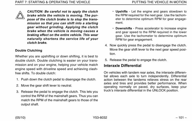
PART 7: STARTING & OPERATING THE VEHICLE PUTTING THE VEHICLE IN MOTION
(05/10) Y53-6032 – 101 –
CAUTION: Be careful not to apply the clutchbrake while the vehicle is moving. The pur-pose of the clutch brake is to stop the trans-mission so that you can shift into a startinggear without grinding. Applying the clutchbrake when the vehicle is moving causes abraking effect on the entire vehicle. This wearnaturally shortens the service life of yourclutch brake.
Double Clutching
Whether you are upshifting or down shifting, it is best todouble clutch. Double clutching is easier on your trans-mission and on your engine, helping your vehicle matchengine speed with driveline speed and achieving clash-free shifts. To double clutch:
1. Push down the clutch pedal to disengage the clutch.
2. Move the gear shift lever to neutral.
3. Release the pedal to engage the clutch. This lets youcontrol the RPM of the mainshaft gears. Thus you canmatch the RPM of the mainshaft gears to those of theoutput shaft.
• Upshifts - Let the engine and gears slowdown tothe RPM required for the next gear. Use the tachom-eter to determine optimum RPM for gear engage-ment.
• Downshifts - Press accelerator to increase engineand gear speed to the RPM required in the lowergear. Use the tachometer to determine optimumRPM for gear engagement.
4. Now quickly press the pedal to disengage the clutch.Move the gear shift lever to the next gear speed posi-tion.
5. Release the pedal to engage the clutch.
Interaxle DifferentialOn vehicles with tandem rear axles, the interaxle differen-tial allows each axle to turn independently. Differentialaction between the tandems relieves stress on the rearaxles and tires and provides better performance. Whenoperating normally on paved, dry surfaces, keep yourtruck’s interaxle differential in the UNLOCK position.
Y53-6032.book Page 101 Monday, May 24, 2010 3:37 PM
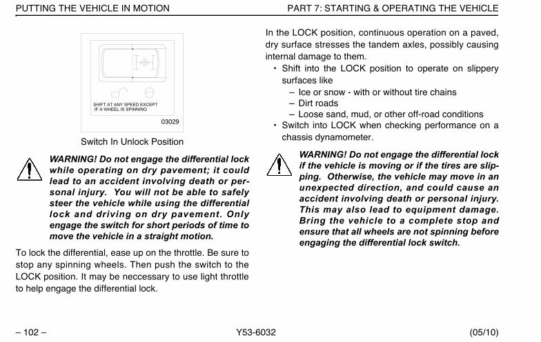
PUTTING THE VEHICLE IN MOTION PART 7: STARTING & OPERATING THE VEHICLE
– 102 – Y53-6032 (05/10)
Switch In Unlock Position
WARNING! Do not engage the differential lockwhile operating on dry pavement; it couldlead to an accident involving death or per-sonal injury. You will not be able to safelysteer the vehicle while using the differentiallock and driving on dry pavement. Onlyengage the switch for short periods of time tomove the vehicle in a straight motion.
To lock the differential, ease up on the throttle. Be sure tostop any spinning wheels. Then push the switch to theLOCK position. It may be neccessary to use light throttleto help engage the differential lock.
In the LOCK position, continuous operation on a paved,dry surface stresses the tandem axles, possibly causinginternal damage to them.
• Shift into the LOCK position to operate on slipperysurfaces like
– Ice or snow - with or without tire chains– Dirt roads– Loose sand, mud, or other off-road conditions
• Switch into LOCK when checking performance on achassis dynamometer.
WARNING! Do not engage the differential lockif the vehicle is moving or if the tires are slip-ping. Otherwise, the vehicle may move in anunexpected direction, and could cause anaccident involving death or personal injury.This may also lead to equipment damage.Bring the vehicle to a complete stop andensure that all wheels are not spinning beforeengaging the differential lock switch.
SHIFT AT ANY SPEED EXCEPT IF A WHEEL IS SPINNING
03029
Y53-6032.book Page 102 Monday, May 24, 2010 3:37 PM
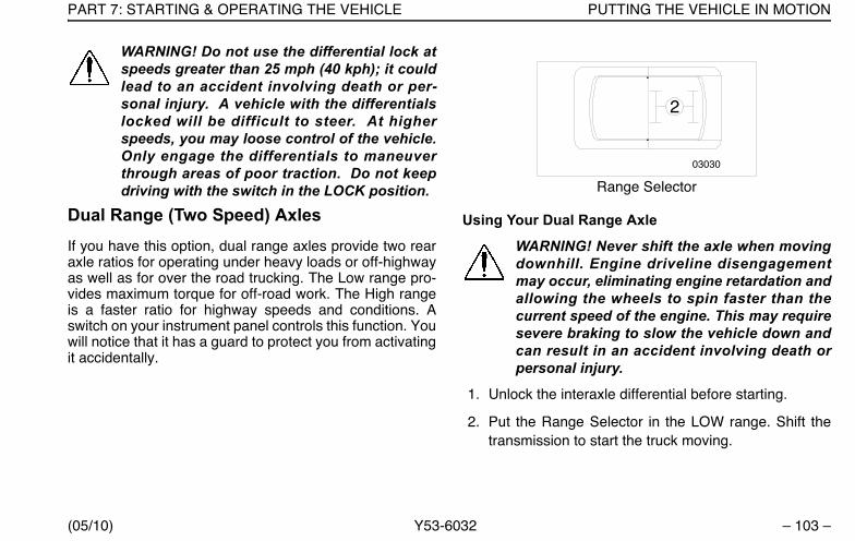
PART 7: STARTING & OPERATING THE VEHICLE PUTTING THE VEHICLE IN MOTION
(05/10) Y53-6032 – 103 –
WARNING! Do not use the differential lock atspeeds greater than 25 mph (40 kph); it couldlead to an accident involving death or per-sonal injury. A vehicle with the differentialslocked will be difficult to steer. At higherspeeds, you may loose control of the vehicle.Only engage the differentials to maneuverthrough areas of poor traction. Do not keepdriving with the switch in the LOCK position.
Dual Range (Two Speed) AxlesIf you have this option, dual range axles provide two rearaxle ratios for operating under heavy loads or off-highwayas well as for over the road trucking. The Low range pro-vides maximum torque for off-road work. The High rangeis a faster ratio for highway speeds and conditions. Aswitch on your instrument panel controls this function. Youwill notice that it has a guard to protect you from activatingit accidentally.
Range Selector
Using Your Dual Range Axle
WARNING! Never shift the axle when movingdownhill. Engine driveline disengagementmay occur, eliminating engine retardation andallowing the wheels to spin faster than thecurrent speed of the engine. This may requiresevere braking to slow the vehicle down andcan result in an accident involving death orpersonal injury.
1. Unlock the interaxle differential before starting.
2. Put the Range Selector in the LOW range. Shift thetransmission to start the truck moving.
03030
2
Y53-6032.book Page 103 Monday, May 24, 2010 3:37 PM
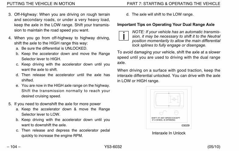
PUTTING THE VEHICLE IN MOTION PART 7: STARTING & OPERATING THE VEHICLE
– 104 – Y53-6032 (05/10)
3. Off-Highway: When you are driving on rough terrainand secondary roads, or under a very heavy load,keep the axle in the LOW range. Shift your transmis-sion to maintain the road speed you want.
4. When you go from off-highway to highway driving,shift the axle to the HIGH range this way:a. Be sure the differential is UNLOCKED.b. Keep the accelerator down and move the Range
Selector lever to HIGH.c. Keep driving with the accelerator down until you
want the axle to shift.d. Then release the accelerator until the axle has
shifted.e. You are now in the HIGH axle range on the highway.
Shift the transmission normally to reach yourdesired cruising speed.
5. If you need to downshift the axle for more powera. Keep the accelerator down & move the Range
Selector lever to LOW.b. Keep driving with the accelerator down until you
want to downshift the axle.c. Then release and depress the accelerator pedal
quickly to increase the engine RPM.
d. The axle will shift to the LOW range.
Important Tips on Operating Your Dual Range Axle
NOTE: If your vehicle has an automatic transmis-sion, it may be necessary to shift it to the Neutralposition momentarily to allow the main differentiallock splines to fully engage or disengage.
To avoid damaging your vehicle, shift the axle at a slowerspeed until you are used to driving with the dual rangeaxle.
When driving on a surface with good traction, keep theinteraxle differential unlocked. You can drive with the axlein LOW or HIGH range.
Interaxle In Unlock
SHIFT AT ANY SPEED EXCEPT IF A WHEEL IS SPINNING
03029
Y53-6032.book Page 104 Monday, May 24, 2010 3:37 PM

PART 7: STARTING & OPERATING THE VEHICLE PUTTING THE VEHICLE IN MOTION
(05/10) Y53-6032 – 105 –
When you are driving with poor traction, lock the differen-tial. When you have the differential locked, drive with theaxle in LOW range only.
Interaxle In Lock
Always UNLOCK the interaxle differential before shiftingthe axle speed range.
CAUTION: If you shift the axle range with theinteraxle differential in LOCK, you could doserious damage to your axles. Never shift theaxle range with the differential locked.
• Park the truck with the Range Selector in LOW.
Automatic and Automated TransmissionAn automatic or automated transmission makes shiftingmuch easier. It remains important to completely under-stand how to operate the transmission to optimize its effi-ciency. Please read the manual for your automatic orautomated transmission included with your vehicle.
WARNING! If your vehicle has a Freedom-line™ transmission, be aware that it can rollbackwards when stopped on a hill or grade, orwhen starting from a stop on a hill or grade.This could cause serious damage, death orpersonal injury. Observe the following guide-lines:
• When stopped on a hill or grade, press thebrake pedal.
• When starting from a stop on a hill or grade,quickly remove your foot from the brakepedal and firmly press on the acceleratorpedal.
Auxiliary TransmissionIf you have an auxiliary transmission, see your transmis-sion manufacturer’s manual for its proper operation.
SHIFT AT ANY SPEED EXCEPT IF A WHEEL IS SPINNING
03029A
Y53-6032.book Page 105 Monday, May 24, 2010 3:37 PM
PUTTING THE VEHICLE IN MOTION PART 7: STARTING & OPERATING THE VEHICLE
– 106 – Y53-6032 (05/10)
If Your Vehicle Must Be TowedFollow these directions to ensure your vehicle is not dam-aged when towing is required.
1. Lift driving wheels off the ground or remove the drive-line and axle shafts before towing the vehicle.
CAUTION: Failure to lift the driving wheels offthe ground or remove the driveline and axleshafts before towing the vehicle could seri-ously damage your vehicle. All lubricatingand clutch application oil pressure is pro-vided by an engine-driven pump, which doesnot work when the engine is stopped. Whenvehicles are towed either by wrecker or piggy-back, lubricant in the top front of the driveaxle will drain to the rear. This will leave thetop components dry, resulting in friction thatwill seriously damage these components.
2. Cover open hubs when removing drive axle shafts.
CAUTION: Water, dirt and other material canenter an open hub or axle. This can contami-nate the axle fluid and cause possible damageto components. Ensure that the hubs are cov-ered with plastic whenever a drive axle shaftis removed.
3. For vehicles with driver-controlled main differentiallock, install the caging bolt before removing the axleshafts for towing.
CAUTION: To avoid damaging your vehicleshift the axle at slower travel speeds until youare used to driving with a dual range axle.
Y53-6032.book Page 106 Monday, May 24, 2010 3:37 PM

PART 7: STARTING & OPERATING THE VEHICLE PUTTING THE VEHICLE IN MOTION
(05/10) Y53-6032 – 107 –
a. Remove the air line and firmly cap
Illustration of Driver-Controlled Main Differential Lockb. Remove the caging bolt from its storage hole.c. Screw the caging bolt into the air line hole. When
fully engaged, a 0.25 - 0.5 in. (6-1/2 mm) space willremain between the air cylinder and the bolt head.This action will lock the differential by pushing a pis-ton into a “lock” position.
CAUTION: Failure to install the caging boltwhen towing vehicles with driver-control maindifferential lock can result in damage by fail-ing to lock internal components in position.
WARNING! Ensure there are no open air lineson the recovered vehicle if the recovery vehi-cle and recovered vehicle brake systems areconnected. An open air line on the recoveredvehicle will cause a leak in the air brake sys-tem of the recovery vehicle possibly causingan accident and death or personal injury.
CAUTION: A recovered vehicle will have nooperational brake system. Additionally, therear axle spring brakes will probably beapplied.
• If you desire to use the recovered vehicle’sbrakes, ensure that the vehicles air systemis connected to that of the recovery vehicle.Also ensure that any air line that has beenremoved from a driver-controlled main dif-ferential lock is firmly capped to preventloss of air pressure from the recovery vehi-cle.
Caging Bolt Storage Location
Air Line - Remove to Install Caging Bolt
Y53-6032.book Page 107 Monday, May 24, 2010 3:37 PM

ANTI-LOCK BRAKING SYSTEM OPERATING INFORMATION PART 7: STARTING & OPERATING THE VEHICLE
– 108 – Y53-6032 (05/10)
• If you don’t desire to use the recoveredvehicle’s brakes, ensure that you cage thespring brakes before attempting to movethe vehicle.
4. Install recovery hitches and rigging.
CAUTION: Connect recovery rigging only tohitches intended for that purpose. Do notattach to bumpers or brackets. Connectionsto other structural parts could damage thevehicle.
5. Follow all state/provincial and local laws that apply tovehicles in tow.
6. Do not tow vehicles at speeds in excess of 55 mph(90 kph).
Returning a Towed Vehicle to Service
You will have to add lubricant to prevent damage afteryour vehicle has been towed.
1. Into the pinion cage, add 1 pint (.47 liter) of lubricant,ORInto the inter-axle differential, add 2 pints (.94 liter) oflubricant. See the Index, under Lubricant Specifica-tions, for the lubricant required by each axle.
2. After adding the specified type and amount of lubri-cant, drive the vehicle. It should be unloaded. Drive 1to 2 miles (1.5 to 3 km) at a speed lower than 25 mph(40 km/h).
This will thoroughly circulate the lubricant through theassembly.
Anti-Lock Braking System Operating InformationA Model 587 is equipped with an anti-lock braking system(ABS). This ABS reduces the possibility of wheel lock-up.If a wheel is about to lock during braking, the ABS willautomatically adjust air pressure to the brake chamberson the appropriate wheel(s) to prevent wheel lock-up. TheABS is automatically turned on when the ignition switch isturned on.
Y53-6032.book Page 108 Monday, May 24, 2010 3:37 PM

PART 7: STARTING & OPERATING THE VEHICLE ANTI-LOCK BRAKING SYSTEM OPERATING INFORMATION
(05/10) Y53-6032 – 109 –
WARNING!
• The brake system is a critical vehicle safetysystem. For the safety of you and othersaround you, have the vehicle submitted forperiodic preventive maintenance checks aswell as having any suspected problemsimmediately checked by an Authorized Ser-vice Center. Failure to properly maintainyour brake system can lead to death or per-sonal injury accidents.
• Do not drive through water deep enough towet brake components, as it may cause thebrakes to work less efficiently than normal.The vehicle's stopping distance may belonger than expected, and the vehicle maypull to the left or right when brakes areapplied, which could contribute to an acci-dent involving death or personal injury.
• Do not rely on an anti-lock brake systemthat is functioning improperly. You couldlose control of the vehicle resulting in anaccident involving death or personal injury.If any ABS lamp goes on while you are driv-ing or stays on after the self-check, thatanti-lock system might not be working. That
ABS may not function in an emergency. Youwill still have conventional brakes, but notanti-lock brakes. If any warning lamp indi-cates a problem, have that ABS checked.
ABS Warning Lamps
Truck/Tractor ABS Warning Lamp
A truck/tractor ABS warning lamp illuminates when theignition switch is first turned on and will remain on until thesystem self-test has been completed successfully. Nor-mally, this ABS lamp will remain on until a speed of nomore than 9 mph has been reached and the speed sen-sors have been checked for correct output. The lampshould remain off after this point unless a failure in thesystem is detected.
CAUTION: If the truck/tractor ABS warninglamp does not illuminate when the ignition isfirst turned on, there is a problem with thebulb or wiring. The driver should have thischecked as soon as possible.
The truck/tractor ABS lamp is located in the warning lampcluster. (See illustration on page 17.).
Y53-6032.book Page 109 Monday, May 24, 2010 3:37 PM
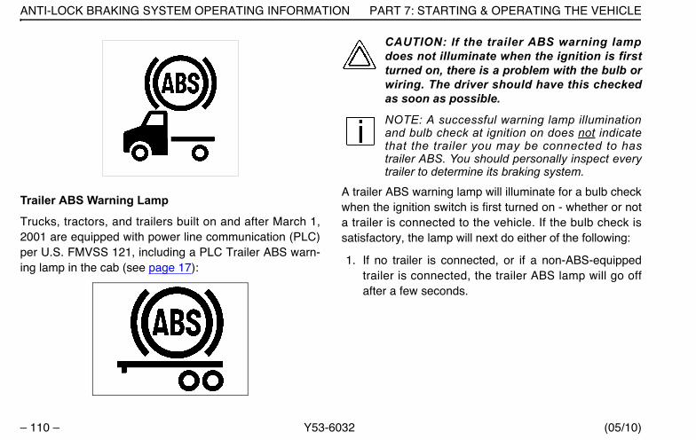
ANTI-LOCK BRAKING SYSTEM OPERATING INFORMATION PART 7: STARTING & OPERATING THE VEHICLE
– 110 – Y53-6032 (05/10)
Trailer ABS Warning Lamp
Trucks, tractors, and trailers built on and after March 1,2001 are equipped with power line communication (PLC)per U.S. FMVSS 121, including a PLC Trailer ABS warn-ing lamp in the cab (see page 17):
CAUTION: If the trailer ABS warning lampdoes not illuminate when the ignition is firstturned on, there is a problem with the bulb orwiring. The driver should have this checkedas soon as possible.
NOTE: A successful warning lamp illuminationand bulb check at ignition on does not indicatethat the trailer you may be connected to hastrailer ABS. You should personally inspect everytrailer to determine its braking system.
A trailer ABS warning lamp will illuminate for a bulb checkwhen the ignition switch is first turned on - whether or nota trailer is connected to the vehicle. If the bulb check issatisfactory, the lamp will next do either of the following:
1. If no trailer is connected, or if a non-ABS-equippedtrailer is connected, the trailer ABS lamp will go offafter a few seconds.
Y53-6032.book Page 110 Monday, May 24, 2010 3:37 PM
PART 7: STARTING & OPERATING THE VEHICLE ANTI-LOCK BRAKING SYSTEM OPERATING INFORMATION
(05/10) Y53-6032 – 111 –
CAUTION:
• The center pin of the 7-way trailer light linemay be constantly powered for ABS. Makesure it will not accidently turn on trailerequipment.
• Do not splice into the non-switchable “Aux-iliary” circuit on the primary 7-way trailerlight line. Doing so may cause the trailerABS to malfunction. This circuit is dedi-cated for trailer ABS power. To add a switch-able “auxiliary” circuit, contact a PeterbiltAuthorized Dealership.
NOTES:
• A “properly connected” ABS-equipped trailer is
– a trailer with PLC hooked up to the J560 con-nector
– a trailer without PLC that is hooked up to anoptional ISO 3731 connector
• For doubles or triples: PLC does not distinguishbetween trailers. An ABS problem in any trailerwill activate the trailer ABS warning lamp.
2. If an ABS-equipped trailer is properly connected, thetrailer ABS warning lamp will remain illuminated for afew more seconds while the trailer ABS is tested.
• If no trailer ABS problems are detected, the lamp willgo off.
• If a trailer ABS problem is detected, the lamp willremain on. The driver should have the trailer’s ABSproblem corrected before the vehicle is driven withthat trailer attached.
Advanced ABS with Stability ControlThis vehicle may be equipped with an optional ElectronicStability Program (ESP). ESP is a feature for ABS-equipped vehicles that reduces the risk of rollovers, jack-knifing and other loss of control. ESP features include RollStability Program (RSP) and Yaw Control.
WARNING! While ESP may reduce the risk ofloosing control of the vehicle, it does not pre-vent an event where the vehicle is not undercontrol. The driver must excercise extremecaution to prevent a rollover or other loss ofcontrol events. Failure to do so may result inan accident involving death or personal injury.
Y53-6032.book Page 111 Monday, May 24, 2010 3:37 PM
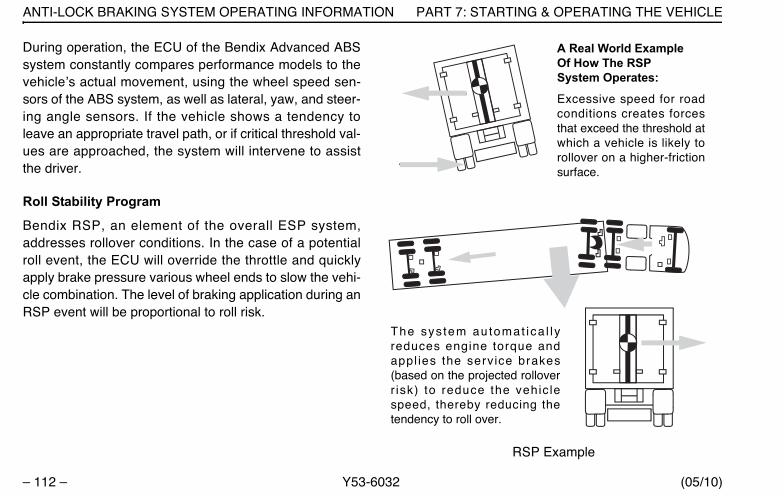
ANTI-LOCK BRAKING SYSTEM OPERATING INFORMATION PART 7: STARTING & OPERATING THE VEHICLE
– 112 – Y53-6032 (05/10)
During operation, the ECU of the Bendix Advanced ABSsystem constantly compares performance models to thevehicle’s actual movement, using the wheel speed sen-sors of the ABS system, as well as lateral, yaw, and steer-ing angle sensors. If the vehicle shows a tendency toleave an appropriate travel path, or if critical threshold val-ues are approached, the system will intervene to assistthe driver.
Roll Stability Program
Bendix RSP, an element of the overall ESP system,addresses rollover conditions. In the case of a potentialroll event, the ECU will override the throttle and quicklyapply brake pressure various wheel ends to slow the vehi-cle combination. The level of braking application during anRSP event will be proportional to roll risk.
RSP Example
A Real World ExampleOf How The RSPSystem Operates:
Excessive speed for roadconditions creates forcesthat exceed the threshold atwhich a vehicle is likely torollover on a higher-frictionsurface.
The sys tem au tomat ica l l yreduces engine torque andappl ies the serv ice brakes(based on the projected rolloverr isk) to reduce the vehic lespeed, thereby reducing thetendency to roll over.
Y53-6032.book Page 112 Monday, May 24, 2010 3:37 PM
PART 7: STARTING & OPERATING THE VEHICLE ANTI-LOCK BRAKING SYSTEM OPERATING INFORMATION
(05/10) Y53-6032 – 113 –
Yaw Stability
Yaw stability counteracts the tendency of a vehicle to spinabout its vertical axis. During operation, if the frictionbetween the road surface and the tires is not sufficient tooppose lateral (side) forces, one or more of the tires canslide, causing the truck/tractor to spin.
These yaw events are referred to as either “under-steer”(where there is a lack of vehicle response to steering inputdue to tire slide on the steer axle) or “over-steer” (wherethe tractor's rear end slides out due to tire slide on the rearaxle) situation. Generally, shorter wheelbase vehicles(tractors, for instance) have less natural yaw stability,while longer wheelbase vehicles (straight trucks, forinstance) have greater natural yaw stability. Factors thatinfluence yaw stability are: wheelbase, suspension, steer-ing geometry, weight distribution front to rear, and vehicletrack width.
Yaw Control
Yaw Control responds to a wide range of low- to high-fric-tion surface scenarios including rollover, jackknife andloss of control. In the case of vehicle slide (over-steer orundersteer situations), the system will reduce the throttleand then brake one or more of the “four corners” of the
vehicle (in addition to potentially applying the trailerbrakes), thus applying a counter-force to better align thevehicle with an appropriate path of travel. For example, inan over-steer situation, the system applies the “outside”front brake; while in an under-steer condition, the “inside”rear brake is applied.
Y53-6032.book Page 113 Monday, May 24, 2010 3:37 PM

ANTI-LOCK BRAKING SYSTEM OPERATING INFORMATION PART 7: STARTING & OPERATING THE VEHICLE
– 114 – Y53-6032 (05/10)
Yaw Control Example
IMPORTANT SAFETY INFORMATION ABOUT THE STABILITY SYSTEM
ESP May Reduce The Vehicle Speed Automati-callyTo minimize unexpected deceleration and reduce the riskof a collision the operator must:
• Avoid aggressive driving maneuvers, such as sharpturns or abrupt lane changes at high speeds, whichmight trigger the stability system.
• Always operate the vehicle safely, drive defensively,anticipate obstacles and pay attention to road,weather and traffic conditions. ABS, ATC and ESPstability systems are no substitute for prudent, carefuldriving.
Towing Doubles Or Triples May Reduce The Effective-ness Of Stability Systems
ESP is designed and optimized for trucks and for tractorsthat tow single trailers. If a tractor equipped with ESP isused to power multiple trailer combinations (known as“doubles” or “triples”) the effectiveness of the ESP systemmay be greatly reduced.
The Bendix® Yaw Control system reduces engine throttleand selectively applies brakes to reduce the vehiclespeed, thereby reducing the tendency to jackknife.
A Real World Example Of How Yaw Control Operates:
Excessive speed exceeds the threshold, creating a situation where a vehicle is likely to spin and jackknife.
Y53-6032.book Page 114 Monday, May 24, 2010 3:37 PM
PART 7: STARTING & OPERATING THE VEHICLE ANTI-LOCK BRAKING SYSTEM OPERATING INFORMATION
(05/10) Y53-6032 – 115 –
WARNING! Exercise extreme care when tow-ing doubles or triples with a vehicle equippedwith Electronic Stability Program. Excessivespeed and aggressive maneuvers, such assharp turns, sudden steering inputs or abruptlane changes should be avoided becausethese maneuvers could cause loss of vehiclecontrol possibly resulting death or severe per-sonal injury.
Limitations Of Stability Systems
The ESP stability system’s effectiveness may be greatlyreduced if:
• The load shifts due to improper retention, accidentdamage or the inherently mobile nature of some loads(for example, hanging meat, live animals or partiallyladen tankers),
• The vehicle has an unusually high or off-set center ofgravity (CG),
• One side of the vehicle drops off the pavement at anangle that is too large to be counteracted by a reduc-tion in speed,
• The vehicle is used to haul double or triple trailer com-binations,
• If very rapidly winding steering inputs are inputted athigh speeds,
• There are mechanical problems with suspension lev-eling of the tractor or trailer resulting in uneven loads,
• The vehicle is maneuvering on a high banked roadcreating either additional side forces due to the weight(mass) of the vehicle or a deviation between expected& actual yaw rates,
• Gusty winds are strong enough to cause significantside forces on the vehicle and any towed vehicles.
To Maximize The Effectiveness Of ESP:
• Loads must be properly secured and evenly distrib-uted at all times.
• Drivers need to exercise extreme caution at all times,and avoid sharp turns, sudden steering inputs orabrupt lane changes at high speeds, particularly if:
– the vehicle hauls loads that could shift,
– the vehicle or load has a high or off-set center ofgravity (CG) when loaded, or
– the vehicle tows doubles or triples.
Y53-6032.book Page 115 Monday, May 24, 2010 3:37 PM
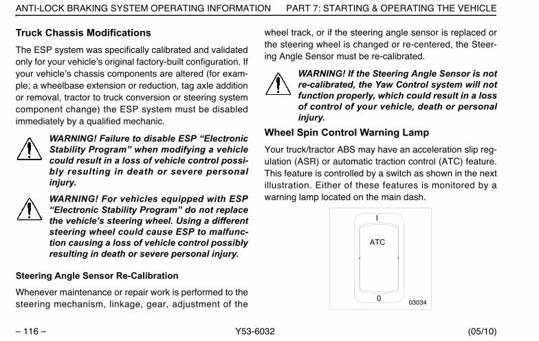
ANTI-LOCK BRAKING SYSTEM OPERATING INFORMATION PART 7: STARTING & OPERATING THE VEHICLE
– 116 – Y53-6032 (05/10)
Truck Chassis ModificationsThe ESP system was specifically calibrated and validatedonly for your vehicle’s original factory-built configuration. Ifyour vehicle’s chassis components are altered (for exam-ple; a wheelbase extension or reduction, tag axle additionor removal, tractor to truck conversion or steering systemcomponent change) the ESP system must be disabledimmediately by a qualified mechanic.
WARNING! Failure to disable ESP “ElectronicStability Program” when modifying a vehiclecould result in a loss of vehicle control possi-bly resulting in death or severe personalinjury.
WARNING! For vehicles equipped with ESP“Electronic Stability Program” do not replacethe vehicle’s steering wheel. Using a differentsteering wheel could cause ESP to malfunc-tion causing a loss of vehicle control possiblyresulting in death or severe personal injury.
Steering Angle Sensor Re-Calibration
Whenever maintenance or repair work is performed to thesteering mechanism, linkage, gear, adjustment of the
wheel track, or if the steering angle sensor is replaced orthe steering wheel is changed or re-centered, the Steer-ing Angle Sensor must be re-calibrated.
WARNING! If the Steering Angle Sensor is notre-calibrated, the Yaw Control system will notfunction properly, which could result in a lossof control of your vehicle, death or personalinjury.
Wheel Spin Control Warning LampYour truck/tractor ABS may have an acceleration slip reg-ulation (ASR) or automatic traction control (ATC) feature.This feature is controlled by a switch as shown in the nextillustration. Either of these features is monitored by awarning lamp located on the main dash..
I
0
ATC
03034
Y53-6032.book Page 116 Monday, May 24, 2010 3:37 PM
PART 7: STARTING & OPERATING THE VEHICLE BRAKE SAFETY AND EMERGENCY
(05/10) Y53-6032 – 117 –
The Wheel Spin Control warning lamp will briefly illumi-nate and then go out when the ignition switch is firstturned on. The Wheel Spin Control warning lamp will illu-minate whenever the ASR or ATC system detects drivewheel spin. The lamp will remain illuminated as long aswheel spin is detected and the ASR or ATC system isapplying the drive wheel brakes or reducing enginetorque. Do not allow the Wheel Spin Control lamp toremain on continuously for an extended length of time.Extended continuous use of the ASR / ATC can causeoverheating of the drive wheel brakes. Engine torque orvehicle speed should be reduced to eliminate wheel spinand prevent excessive application of the ASR/ATC sys-tem.
Except for checking for proper illumination of the ABS andWheel Spin Control warning lamps when first starting thevehicle, and for monitoring these lamps while driving, nospecial operating procedures are required. For detailedsystem description, see service literature for your specificABS that was provided with your vehicle.
Brake Safety and Emergency To stop your vehicle in an emergency, vary the servicebrake application pressure to provide maximum brakingforce without locking the wheels. Use engine compressionto assist the service brakes; i.e., don’t depress the clutchpedal until the engine reaches idle speed.
WARNING!
• Do not operate the vehicle in the event of amalfunction in any air circuit. The vehicleshould not be operated until the system isrepaired and both braking circuits, includ-ing all pneumatic and mechanical compo-nents, are working properly. Loss of systemair can cause the service brakes not tofunction resulting in the sudden applicationof the spring brakes causing wheel lock-up,loss of control, or overtake by followingvehicles. You could be in an accident, bekilled or severely injured.
Y53-6032.book Page 117 Monday, May 24, 2010 3:37 PM
BRAKE SAFETY AND EMERGENCY PART 7: STARTING & OPERATING THE VEHICLE
– 118 – Y53-6032 (05/10)
WARNING! Unless you have an anti-lock brak-ing system, always avoid completely depress-ing the service brake pedal, if possible, evenduring emergency braking. Depressing thebrake pedal too aggressively can cause thewheels to lock, which can lead to an uncon-trolled skid and could cause an accidentinvolving death or personal injury.
Overheated BrakesUnder normal braking conditions, the energy generatedwill bring the internal brake drum temperature to about500° F (260° C). This is well within the safe zone: Themaximum safe temperature of linings for drum type brakesis usually about 800° F (427° C).
But if service brakes are used improperly or for prolongedperiods, internal brake drum temperatures may commonlyexceed 800° F (427° C). Such brake overheating may bedetected by a burning smell or smoke coming from adrum. If this occurs, you should immediately stop andcheck for cracked brake drums or lining fires. If neitherexists, get back behind the wheel and resume a slowspeed as soon as possible to cool the brakes.
Parking Brakes and Their UseThe yellow diamond-shaped knob on your instrumentpanel controls your parking brakes. These are springbrakes which you activate by releasing air pressure fromtheir chambers. When they are not in use, air pressurecompresses the springs and releases the brakes. But put-ting the valve in the Park position exhausts air from thechambers and allows the springs to extend and apply thebrakes. Also, if your system air drops below the safe oper-ating level, the spring brakes will apply automatically,bringing your vehicle to a stop.
WARNING! On trailers built before March 1975you may not have parking brakes if the trailerreservoir pressure leaks down. If you dependon them to hold your vehicle, they couldrelease, causing a serious accident involvingdeath or personal injury. These older trailershave emergency brakes not designed forparking. They will apply only if there isenough trailer reservoir pressure. Don’t useyour trailer emergency brakes for parking.Apply your tractor parking valve too.
Y53-6032.book Page 118 Monday, May 24, 2010 3:37 PM

PART 7: STARTING & OPERATING THE VEHICLE BRAKE SAFETY AND EMERGENCY
(05/10) Y53-6032 – 119 –
Red / Yellow Controls
WARNING! • Do not leave the cab without applying the
parking brake. The truck could roll and causean accident involving death or personal injury.Always apply the parking brake before youleave the cab.
• Stopping with the parking brake controls cancause a sudden wheel lock-up, loss of control,or can cause you to be overtaken by followingvehicles. You could be killed or severelyinjured. Never pull out the parking brake valvewhile the vehicle is moving.
• Do not use the trailer hand brake or servicebrakes to park and hold an unattended vehi-cle—use the parking brakes. Because servicebrakes work with air pressure, these brakescould slowly release. Your vehicle could roll,causing an accident involving death or per-sonal injury. Someone could be hurt or killed.Never rely on the service brakes to hold aparked vehicle.
• Never drive your vehicle with the parkingbrake applied. Always release the parkingbrakes prior to moving the vehicle. Failure todisengage the parking brakes prior to moving
02909
Y53-6032.book Page 119 Monday, May 24, 2010 3:37 PM
BRAKE SAFETY AND EMERGENCY PART 7: STARTING & OPERATING THE VEHICLE
– 120 – Y53-6032 (05/10)
your vehicle could result in excessive heatbuild-up in the brake system, resulting in afire.
NOTE: Today’s diesel electronic engines havesignificant torque and startability power at lowRPM. Combinations of engine speed and avail-able torque may over-power the vehicle’s parkingbrakes.
To apply all your parking brakes, pull the yellow knobOut. The parking brakes will set. And the trailer air supplyvalve (red octagon knob) will automatically pop out,releasing air pressure and setting the trailer brakes.
CAUTION: Do not try to put the vehicle inmotion before pressure in the system reaches100 psi (689 kPa) because the wheels arelocked by the spring brake action. Unneces-sary stress and possible brake malfunctioncould occur if the vehicle is forced to movebefore the air system reaches 100 psi (689kPa).
To release your truck or tractor brakes ONLY, push inthe yellow knob. Your trailer will remain parked.
• To release the trailer brakes ONLY, push in the redknob. The truck or tractor will remain parked.
• To release the full combination of brakes, push inBOTH yellow and red knobs.
Trailer Air Supply ValveThe red octagon knob controls the air supply to the trailer.To supply air to the trailer system and release the trailerparking brakes:
• Allow the tractor air system pressure to build up tooperating level.
• Push the red knob in.
• Hold the red knob in by hand until the trailer air pres-sure builds to a pre-set level, about 45 psi. At thispoint it will remain in.
The yellow knob will remain out; the tractor will remainparked. If you ever have a failure or disconnect of the airsupply hose to the trailer, the trailer parking brakes willset. The red knob will automatically pop out and seal offthe tractor air reservoirs to protect the tractor air systempressure. When operating the tractor “bobtail”: The redknob must remain out to protect the tractor air systempressure.
Y53-6032.book Page 120 Monday, May 24, 2010 3:37 PM
PART 7: STARTING & OPERATING THE VEHICLE BRAKE SAFETY AND EMERGENCY
(05/10) Y53-6032 – 121 –
Manually Releasing Spring BrakesThere may be an occasion when you need to tow the vehi-cle but the air system does not produce enough operatingpressure to release the parking brakes. For these situa-tions, the spring brakes may be manually released toallow the vehicle to be towed. This section details how torelease a drum or an air disc brake.
WARNING!
• Do not operate a vehicle when the springbrakes have been released manually. Driv-ing a vehicle that has had its spring brakesmanually released is extremely dangerous.You would probably have no brakes at all,which could cause death or serious injury.
• Releasing the spring brakes on an unse-cured vehicle could lead to an accident. Thetruck could roll, causing death or severeinjury. Always secure the truck with wheelchocks, chains, or other safe means to pre-vent rolling before manually releasing thespring brakes.
• Disassembling the spring brake chamber isdangerous and could cause death or seri-ous injury. These chambers contain a pow-erful spring that is compressed. Suddenrelease of this spring could cause you to bebadly injured. Do not disassemble a springbrake chamber.
NOTE: The primary purpose of the manualrelease feature is to permit the vehicle to betowed to a repair facility.
Y53-6032.book Page 121 Monday, May 24, 2010 3:37 PM
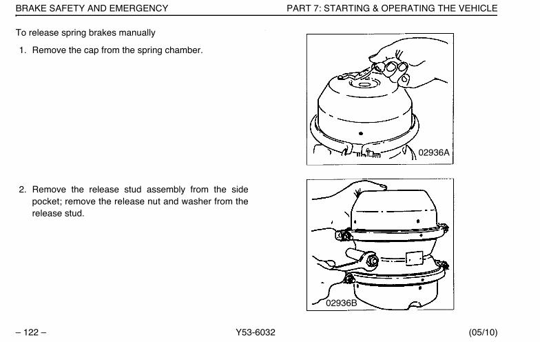
BRAKE SAFETY AND EMERGENCY PART 7: STARTING & OPERATING THE VEHICLE
– 122 – Y53-6032 (05/10)
To release spring brakes manually
1. Remove the cap from the spring chamber.
2. Remove the release stud assembly from the sidepocket; remove the release nut and washer from therelease stud.
:
02936A
02936B
Y53-6032.book Page 122 Monday, May 24, 2010 3:37 PM
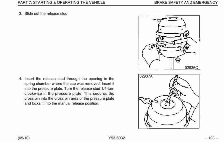
PART 7: STARTING & OPERATING THE VEHICLE BRAKE SAFETY AND EMERGENCY
(05/10) Y53-6032 – 123 –
3. Slide out the release stud
4. Insert the release stud through the opening in thespring chamber where the cap was removed. Insert itinto the pressure plate. Turn the release stud 1/4-turnclockwise in the pressure plate. This secures thecross pin into the cross pin area of the pressure plateand locks it into the manual release position.
02936C
02937A
Y53-6032.book Page 123 Monday, May 24, 2010 3:37 PM
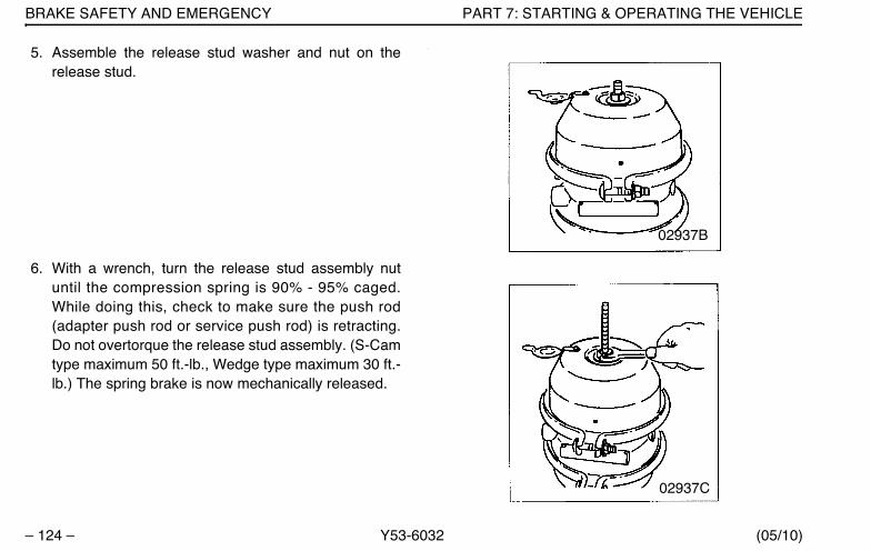
BRAKE SAFETY AND EMERGENCY PART 7: STARTING & OPERATING THE VEHICLE
– 124 – Y53-6032 (05/10)
5. Assemble the release stud washer and nut on therelease stud.
6. With a wrench, turn the release stud assembly nutuntil the compression spring is 90% - 95% caged.While doing this, check to make sure the push rod(adapter push rod or service push rod) is retracting.Do not overtorque the release stud assembly. (S-Camtype maximum 50 ft.-lb., Wedge type maximum 30 ft.-lb.) The spring brake is now mechanically released.
:
02937B
02937C
Y53-6032.book Page 124 Monday, May 24, 2010 3:37 PM
PART 7: STARTING & OPERATING THE VEHICLE BRAKE SAFETY AND EMERGENCY
(05/10) Y53-6032 – 125 –
RetardersVarious retarders are available which function against theengine, driveline, or transmission. These are devices thatuse your engine’s power to slow down your vehicle. Theysave wear and tear on your service brakes and can be asafety feature, too, because they can keep your brakesfrom overheating.
Ideally, you should always slow your vehicle with yourretarder (where permitted by law) and use your servicebrakes only for stopping completely. Operating this waywill greatly prolong the life of your brakes.
WARNING!
• In an emergency, the retarder might notstop you fast enough to prevent an acci-dent. You could be killed or severely injuredif you relied only on your retarder. Use theservice brakes for quick stops. The retarderis not an emergency brake.
• The retarder is NOT intended as the primarybrake for the vehicle, nor is it an emergencybrake. The retarder only helps the servicebrakes by using pressure to slow the driv-etrain. Use the service brakes for quickstops.
• Do not use the retarder when operating onroad surfaces with poor traction (such aswet, icy, or snow covered roads or gravel).Retarders can cause the wheels to skid on aslippery surface. You could lose control ofthe vehicle if the wheels begin to skid,resulting in an accident involving death orpersonal injury.
Y53-6032.book Page 125 Monday, May 24, 2010 3:37 PM
EXHAUST AFTER-TREATMENT SYSTEM PART 7: STARTING & OPERATING THE VEHICLE
– 126 – Y53-6032 (05/10)
Driving Bobtail or with an Unloaded Trailer
We recommend that you do not use your engine retarderto slow down when you are bobtailing or pulling an emptytrailer.
WARNING! Using an engine retarder cancause a wheel lockup. The trailer is not load-ing the tires enough to give the traction youmay need. When you are bobtail or unloaded,you can have a serious accident if yourwheels lock suddenly during braking. Youcould be killed or injured. Don’t use yourretarder when you are driving bobtail or withan unloaded trailer.
Exhaust After-Treatment SystemNOTE: The emission warning lamps and emissionswitch functions described below supersede thoselisted in the Engine manufacturer's Operator andMaintenance manual. For additional EmissionsAftertreatment information specific to your engine,see the Engine manufacturer's Operation andMaintenance Manual supplied in your vehicle. Allother lamp and switch functionality described inthe manual are still valid.
In order to meet EPA engine emission requirements, vehi-cles will have an exhaust After-Treatment System (ATS)which includes a Diesel Particulate Filter (DPF), Regener-ation Switch and warning lights. The DPF will trap sootfrom the engine exhaust gases. The ATS will periodicallyregenerate the DPF.
The Regeneration Switch is mounted on the dash and canoverride the ATS. Various situations may require theoperator to use the functions of this switch. Refer to“Regeneration Switch” on page 51 to view the regenera-tion switch and its use. In addition, refer to “ParkedRegeneration” on page 131 and “Stop an Automatic orParked Regeneration” on page 133 for more operatinginformation.
ATS specific warning lights and indicator symbols willreside in the driver information display unit.
Functionality / Notification InformationThe ATS will regenerate the DPF by using hot exhaustgases normally generated by the engine. This typicallyoccurs during highway operation. This is referred to as a
Y53-6032.book Page 126 Monday, May 24, 2010 3:37 PM

PART 7: STARTING & OPERATING THE VEHICLE EXHAUST AFTER-TREATMENT SYSTEM
(05/10) Y53-6032 – 127 –
"Passive" Regeneration and is transparent to the opera-tion of the vehicle.
Occasionally, the exhaust gases are too cool for passiveregeneration. When this occurs, the ATS will regeneratethe DPF by increasing the exhaust temperature. This isreferred to as an "Automatic" Regeneration and is alsotransparent to the operation of vehicle. An AutomaticRegeneration event typically lasts 30 minutes. During andshortly after the event, the exhaust gases from the DPFmay reach temperatures in excess of 650 C (1200 F). Seethe information in the table below on probable causes andrecommended actions related to the warning lights andindicator symbols of the ATS.
The ATS may not be able to regenerate the DPF when thevehicle is driven at extended low speeds or with frequentstart and stops. In such cases, warning lights and indica-tor symbols will alert the operator to take action. The oper-ator should be aware of whether the lights are on alone orin combination with others. The following table willdescribe each warning light(s) and what actions areneeded from the operator.
Y53-6032.book Page 127 Monday, May 24, 2010 3:37 PM
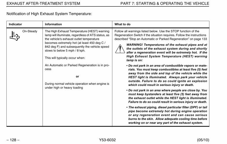
EXHAUST AFTER-TREATMENT SYSTEM PART 7: STARTING & OPERATING THE VEHICLE
– 128 – Y53-6032 (05/10)
Notification of High Exhaust System Temperature:
Indicator Information What to do
On-Steady The High Exhaust Temperature (HEST) warning lamp will illuminate, regardless of ATS status, as the vehicle's exhaust outlet temperature becomes extremely hot (at least 450 deg C / 842 deg F) and subsequently the vehicle speed slows to below 5 mph / 8 kph.
This will typically occur when:
An Automatic or Parked Regeneration is in pro-cess
or
During normal vehicle operation when engine is under high or heavy loading
Follow all warnings listed below. Use the STOP function of the Regeneration Switch if the situation requires. Follow the instructions described “Stop an Automatic or Parked Regeneration” on page 133
WARNING! Temperatures of the exhaust pipes and atthe outlets of the exhaust system during and shortlyafter a regeneration event will be extremely hot. If theHigh Exhaust System Temperature (HEST) warninglamp is on:
• Do not park in an area of combustible vapors or mate-rials. You must keep combustibles at least five (5) feetaway from the side and top of the vehicle while theHEST light is illuminated. Always park your vehicleoutside. Failure to do so could ignite an explosionwhich could result in serious injury or death.
• Do not park in an area where people are close by. Youmust keep bystanders at least five (5) feet away fromthe exhaust outlet while the HEST light is illuminated.Failure to do so could result in serious injury or death.
• The exhaust piping, diesel particular filter (DPF) or tailpipe become extremely hot during engine operationor any regeneration event and can cause seriousburns to the skin. Allow adequate cooling time beforeworking on or near any part of the exhaust system.
Y53-6032.book Page 128 Monday, May 24, 2010 3:37 PM

PART 7: STARTING & OPERATING THE VEHICLE EXHAUST AFTER-TREATMENT SYSTEM
(05/10) Y53-6032 – 129 –
Notification That Regeneration Is Required:
Indicator Information What to do
On Steady The DPF status indicator symbol will illu-minate when the soot level in the DPF is above the desired level and it needs regenerating.
The DPF needs regenerating soon. Follow the instructions described “DPF Regeneration” on page 131
NOTE: If you ignore the warning lamp and do not initiateregeneration at the soonest, safest possible time, the DPFwill become increasingly clogged with soot and can lead toengine shutdown.
Blink once every second
The DPF status indicator symbol will blink when the soot level in the DPF continues to stay above the desired level and it needs regenerating.
Regenerate the DPF as soon as safely possible. Follow the instructions described “DPF Regeneration” on page 131
CAUTION: If you do not initiate regeneration after the DPFIndicator lamp is blinking, you only have a short time beforethe check engine light will illuminate and the engine will gointo protection mode and de-rate power.
Blinking
On Steady
The DPF status indicator symbol will blink when the soot level in the DPF continues to stay above the desired level and it MUST be regenerated.
The engine will de-rate power.
Regenerate the DPF immediately. Follow the instructions described “DPF Regeneration” on page 131.
CAUTION: If you do not initiate regeneration after the DPFIndicator lamp is blinking and the check engine light is illu-minated, you only have a short time before the stop enginelight will illuminate and the engine will automatically beginto shutdown.
Y53-6032.book Page 129 Monday, May 24, 2010 3:37 PM
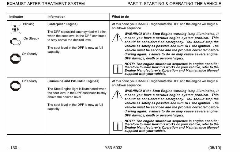
EXHAUST AFTER-TREATMENT SYSTEM PART 7: STARTING & OPERATING THE VEHICLE
– 130 – Y53-6032 (05/10)
Blinking
On Steady
On Steady
(Caterpillar Engine)
The DPF status indicator symbol will blink when the soot level in the DPF continues to stay above the desired level
The soot level in the DPF is now at full capacity.
At this point, you CANNOT regenerate the DPF and the engine will begin a shutdown sequence.
WARNING! If the Stop Engine warning lamp illuminates, itmeans you have a serious engine system problem. Thisshould be considered an emergency. You should stop thevehicle as safely as possible and turn OFF the ignition. Thevehicle must be serviced and the problem corrected beforedriving again. Failure to do so may cause severe engine,DPF damage, death or personal injury.
NOTE: The engine shutdown sequence is engine specific;therefore to learn how this works on your vehicle, refer to theEngine Manufacturer's Operation and Maintenance Manualsupplied with your vehicle.
On Steady (Cummins and PACCAR Engines)
The Stop Engine light is illuminated when the soot level in the DPF continues to stay above the desired level
The soot level in the DPF is now at full capacity.
At this point, you CANNOT regenerate the DPF and the engine will begin a shutdown sequence.
WARNING! If the Stop Engine warning lamp illuminates, itmeans you have a serious engine system problem. Thisshould be considered an emergency. You should stop thevehicle as safely as possible and turn OFF the ignition. Thevehicle must be serviced and the problem corrected beforedriving again. Failure to do so may cause severe engine,DPF damage, death or personal injury.
NOTE: The engine shutdown sequence is engine specific;therefore to learn how this works on your vehicle, refer to theEngine Manufacturer's Operation and Maintenance Manualsupplied with your vehicle.
Indicator Information What to do
Y53-6032.book Page 130 Monday, May 24, 2010 3:37 PM

PART 7: STARTING & OPERATING THE VEHICLE EXHAUST AFTER-TREATMENT SYSTEM
(05/10) Y53-6032 – 131 –
DPF RegenerationCarefully read the following instructions to regenerate theDPF. If you have any problems or difficulties contact yournearest Peterbilt authorized dealer for assistance.
The After-Treatment System (ATS) needs conditions typi-cally found in highway driving to regenerate the DPF. Ifyour DPF Indicator lamp is illuminated, the easiest optionis to help the ATS by proceeding to the nearest highway.
• For the three position switch only, make sure theRegeneration Switch is in the CENTER position.
• Select a highway that has a posted legal speed ofmore than 40 mph.
• Drive your vehicle until the DPF light goes off. Thismay take 30 - 45 minutes of speeds greater than 20mph (32 kph) for a Caterpillar engine or 40 mph (64kph) for a PACCAR or Cummins engine.
If your operation or planned route in the immediate futurelimits your ability to reach highway speeds, proceed to thenext section titled Parked Regeneration.
Parked Regeneration
In very limited applications or operations the DPF must beregenerated by initiating a Parked Regeneration. Followthese six steps to initiate a Parked Regeneration:
1. Pull the vehicle over to a safe location2. Ensure no one is in the immediate vicinity to the tail
pipe3. Maintain a minimum of 5 feet of clearance to any com-
bustible materials from the edge and top of the vehicle
WARNING! Parking the vehicle too close toany combustible materials or vapors maystart a fire, ignite an explosion or burn some-one standing close by. Before pushing theRegeneration switch on the dash, walkaround your vehicle and ensure you have atleast five (5) feet clearance from the sides andtop of your vehicle to any combustibles.Ensure no one is in the immediate vicinity tothe tailpipe. Failure to do so could cause afire or lead to death or serious injury to youand/or bystanders.
Y53-6032.book Page 131 Monday, May 24, 2010 3:37 PM

EXHAUST AFTER-TREATMENT SYSTEM PART 7: STARTING & OPERATING THE VEHICLE
– 132 – Y53-6032 (05/10)
WARNING! Never initiate an regeneration in aclosed building or enclosure. Always parkyour vehicle outside and ensure no one is inthe immediate vicinity. Failure to do so couldignite an explosion or harm bystanders whichcould result in death or serious injury.
NOTES:Typical operation areas or materials thatcan contain explosive vapors, flammable materi-als or people in close proximity of the vehicle are
• Fuel depots
• Grain elevators
• Dry grass, leaves or trees
• Transfer refuse stations/dumps
• Parking lots
• Load/unload terminals
NOTE: While the list above may appear compre-hensive, it is your responsibility to take the neces-sary p recau t ions and be aware o f yoursurroundings and ensure that no combustibles(materials or vapors) or bystanders are close bybefore initiating a regeneration.
4. Verify that the following conditions are met before pro-ceeding. A Parked Regeneration will not initiate if anyof these conditions are not met.
• Parking brake is applied / set
• Engine is at low idle
• No throttle, brake or clutch applied
• PTO is disengaged
• Transmission is in neutral5. Get out and walk all around vehicle to ensure that the
vehicle is at least 5 feet away from all combustiblematerials and no one is in the immediate vicinity.
6. Climb back into the vehicle7. Push the Regeneration (START) Switch located on
the dash for at least 4 -8 seconds and release the but-ton to initiate a Parked Regeneration.
Y53-6032.book Page 132 Monday, May 24, 2010 3:37 PM

PART 7: STARTING & OPERATING THE VEHICLE EXHAUST AFTER-TREATMENT SYSTEM
(05/10) Y53-6032 – 133 –
NOTE: Acknowledgment that a Parked Regener-ation has initiated will vary by engine. The mostpredominant acknowledgement to you will be anincrease in engine RPM and overall enginenoise.
NOTE: The time delay between when the regen-eration switch has been pushed and releasedand when the system starts regenerating mayvary by engine. A Parked Regeneration may take30 or more seconds to initiate as the ATS systemconducts various self-checks to verify all the sys-tem requirements have been met.
NOTE: A Parked Regeneration will initiate only ifthe DPF status light is illuminated or blinking.
If you are unable to initiate a Parked regeneration and theDPF status light is illuminated, contact your nearest Peter-bilt authorized dealer for assistance.
Stop an Automatic or Parked RegenerationA three position switch with a START, Center, and STOPposition will allow the operator to stop a regeneration. If
the regeneration switch is a two position switch, then theoperator will not have the ability to stop a regenerationand this section will not apply.
WARNING! If the vehicle’s regenerationswitch does not have a STOP position, neverallow the vehicle to remain inside a buildingsuch as a service bay, shop or building ofany kind during an Automatic regeneration.Failure to do so could ignite an explosionwhich could result in death or serious injuryto you and/or bystanders.
Vehicles with a three position switch provides the operatorwith the ability to STOP an Automatic or Parked Regener-ation. Since Automatic Regenerations can occur at anytime with this engine, you must depress the STOP portionof the Regeneration Switch ANYTIME you plan to driveyour vehicle into a building, enclosure or area where theactivation of a regeneration is not allowed. If the regener-ation does not stop, turn the vehicle ignition OFF.
Y53-6032.book Page 133 Monday, May 24, 2010 3:37 PM

STOPPING THE ENGINE PART 7: STARTING & OPERATING THE VEHICLE
– 134 – Y53-6032 (05/10)
WARNING! Never allow an Automatic regen-eration to automatically start while inside abuilding such as a service bay, shop or build-ing of any kind. Any time you are parkingyour vehicle inside a building or enclosure,ALWAYS press the Regeneration (STOP)switch prior to entering the building. Failureto do so could ignite an explosion whichcould result in death or serious injury to youand/or bystanders.
WARNING! Never initiate a Parked Regener-ation in a closed building or enclosure.Always park your vehicle outside. Failure todo so could ignite an explosion which couldresult in death or serious injury to you and/orbystanders.
CAUTION: Do not leave the switch in theSTOP position unless you need to cancel orstop regeneration. Leaving the switch inthe STOP position for extended periods oftime will result in increased soot levels inthe DPF.
Stopping The EngineBefore Stopping The EngineA hot engine stores a great amount of heat. And it doesn’tcool down immediately after you shut it off. Always coolyour engine down before shutting it off. You will greatlyincrease its service life.
Idle the engine at 1000 RPM for five minutes. Then lowidle for thirty seconds before shutdown. This will allow cir-culating coolant and lubricating oil to carry away heat fromthe cylinder head, valves, pistons, cylinder liners, turbo-charger, and bearings. This way you can prevent seriousengine damage that may result from uneven cooling.
Turbochargers
This cooling-down practice is especially important on aturbocharged engine. The turbocharger contains bearingsand seals that are subjected to hot exhaust gases. Whilethe engine is operating, heat is carried away by circulatingoil. If you stop the engine suddenly after a hard run, thetemperature of the turbocharger could rise as much as
Y53-6032.book Page 134 Monday, May 24, 2010 3:37 PM
PART 7: STARTING & OPERATING THE VEHICLE STOPPING THE ENGINE
(05/10) Y53-6032 – 135 –
100°F (55°C) above the temperature reached during oper-ation. A sudden rise in temperature like this could causethe bearings to seize or the oil seals to loosen.
Refuel Before the Final StopAir space in your fuel tanks allows water to condensethere. To prevent this condensation while you are stopped,fill your tanks to 95% of capacity.
WARNING! Do not carry additional fuel con-tainers in your vehicle. Fuel containers, eitherfull or empty, may leak, explode, and cause orfeed a fire. Do not carry extra fuel containers,even empty ones are dangerous.• Diesel fuel in the presence of an ignition
source (such as a cigarette) could cause anexplosion. You could be killed or seriouslyinjured. A mixture of gasoline or alcoholwith diesel fuel increases this risk of explo-sion.
• Do not remove a fuel tank cap near an openflame.
• Use only the fuel and/or additives recom-mended for your engine.
Final StopTo make sure your vehicle is ready to go after a long stop(such as over night), please follow the suggestions below.Your vehicle will be easier to get going when you areready, and it will be safer for anyone who might be aroundit. Please remember, too, that in some states it is illegal toleave the engine running and the vehicle unattended.
Final Stopping Procedures
1. Set the parking brake before leaving the driver’s seat.To hold your vehicle while it is parked, don’t rely on
• Air Brakes
• Hand Control Valve for Trailer Brakes
• Engine Compression
WARNING! Using the trailer hand brake or airbrakes to hold a parked vehicle is dangerous.Because they work with air pressure, thesebrakes could come loose. Your vehicle couldroll, causing an accident involving death orpersonal injury. Always set the parkingbrakes. Never rely on the trailer hand brake ortruck air brakes to hold a parked vehicle.
Y53-6032.book Page 135 Monday, May 24, 2010 3:37 PM
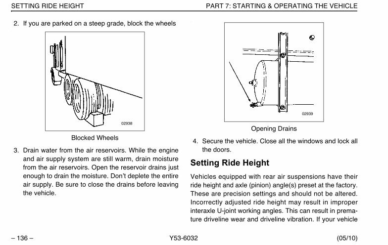
SETTING RIDE HEIGHT PART 7: STARTING & OPERATING THE VEHICLE
– 136 – Y53-6032 (05/10)
2. If you are parked on a steep grade, block the wheels.
Blocked Wheels
3. Drain water from the air reservoirs. While the engineand air supply system are still warm, drain moisturefrom the air reservoirs. Open the reservoir drains justenough to drain the moisture. Don’t deplete the entireair supply. Be sure to close the drains before leavingthe vehicle.
.
Opening Drains
4. Secure the vehicle. Close all the windows and lock allthe doors.
Setting Ride HeightVehicles equipped with rear air suspensions have theirride height and axle (pinion) angle(s) preset at the factory.These are precision settings and should not be altered.Incorrectly adjusted ride height may result in improperinteraxle U-joint working angles. This can result in prema-ture driveline wear and driveline vibration. If your vehicle
02938
02939
Y53-6032.book Page 136 Monday, May 24, 2010 3:37 PM
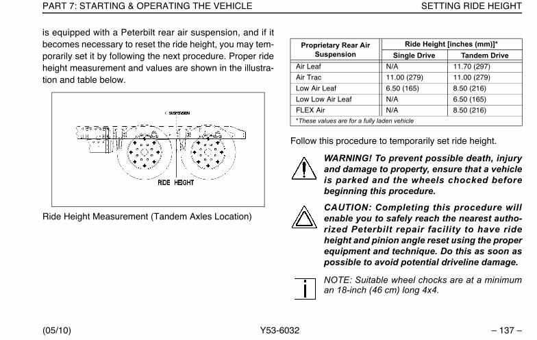
PART 7: STARTING & OPERATING THE VEHICLE SETTING RIDE HEIGHT
(05/10) Y53-6032 – 137 –
is equipped with a Peterbilt rear air suspension, and if itbecomes necessary to reset the ride height, you may tem-porarily set it by following the next procedure. Proper rideheight measurement and values are shown in the illustra-tion and table below.
Ride Height Measurement (Tandem Axles Location)
Follow this procedure to temporarily set ride height.
WARNING! To prevent possible death, injuryand damage to property, ensure that a vehicleis parked and the wheels chocked beforebeginning this procedure.
CAUTION: Completing this procedure willenable you to safely reach the nearest autho-rized Peterbilt repair facility to have rideheight and pinion angle reset using the properequipment and technique. Do this as soon aspossible to avoid potential driveline damage.
NOTE: Suitable wheel chocks are at a minimuman 18-inch (46 cm) long 4x4.
Proprietary Rear Air Suspension
Ride Height [inches (mm)]*Single Drive Tandem Drive
Air Leaf N/A 11.70 (297)
Air Trac 11.00 (279) 11.00 (279)
Low Air Leaf 6.50 (165) 8.50 (216)
Low Low Air Leaf N/A 6.50 (165)
FLEX Air N/A 8.50 (216)*These values are for a fully laden vehicle
Y53-6032.book Page 137 Monday, May 24, 2010 3:37 PM
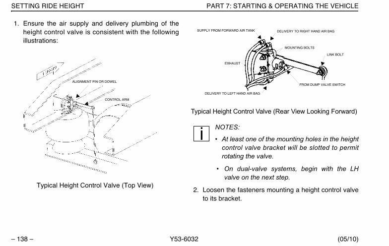
SETTING RIDE HEIGHT PART 7: STARTING & OPERATING THE VEHICLE
– 138 – Y53-6032 (05/10)
1. Ensure the air supply and delivery plumbing of theheight control valve is consistent with the followingillustrations:
Typical Height Control Valve (Top View)
Typical Height Control Valve (Rear View Looking Forward)
NOTES:
• At least one of the mounting holes in the heightcontrol valve bracket will be slotted to permitrotating the valve.
• On dual-valve systems, begin with the LHvalve on the next step.
2. Loosen the fasteners mounting a height control valveto its bracket.
ALIGNMENT PIN OR DOWEL
CONTROL ARM
FROM DUMP VALVE SWITCH
LINK BOLT
DELIVERY TO LEFT HAND AIR BAG
EXHAUST
SUPPLY FROM FORWARD AIR TANK DELIVERY TO RIGHT HAND AIR BAG
MOUNTING BOLTS
Y53-6032.book Page 138 Monday, May 24, 2010 3:37 PM
PART 7: STARTING & OPERATING THE VEHICLE SETTING RIDE HEIGHT
(05/10) Y53-6032 – 139 –
WARNING! The rear of a vehicle will dropabout 3 1/2 inches (88 mm) when the airsprings are deflated. Ensure that no personsor objects that could be killed, injured ordamaged are under the vehicle before deflat-ing the air springs.
WARNING! To minimize risk of damage ordeath or injury, do not use a dump valve todeflate the air springs. Rotate the heightcontrol valve(s) manually to ensure positivecontrol of air spring deflation.
3. Rotate the valve either clockwise or counterclockwiseuntil air pressure in the air springs provides the rideheight specified for that suspension. Measure the rideheight from the bottom of the frame rail to the approx-imate centerline of the rearmost drive axle hub:
WARNING! Do not allow the air springs tooverinflate. Overinflating the air springs maycause them to burst which can lead to deathor personal injury from debris or the frame.
• For tandem axles, make the vertical measurementat the centerline of the suspension (see illustrationon page 137).
• For a single axle, make the measurement in front ofthe axle, in the area forward of the tires but not pastthe suspension bracket.
4. When at the correct ride height, ensure that the heightcontrol valve lever is in the neutral position, theninstall either the built-in alignment pin or a 1/8-inch (3mm) dowel (see page 138).
5. Torque the mounting fasteners to 55–75 Lb. in. (6.2–8.5 N.m.).
6. Remove the alignment pin or dowel.
7. Repeat Steps 2 through 6 above for the RH valve onvehicles with a dual-valve system.
Driving With Deflated Air SpringsIf an air spring is ruptured, there will be enough air pres-sure to drive the vehicle to a safe stop off the highway toinvestigate the problem.
Y53-6032.book Page 139 Monday, May 24, 2010 3:37 PM
DRIVING TIPS AND TECHNIQUES PART 7: STARTING & OPERATING THE VEHICLE
– 140 – Y53-6032 (05/10)
WARNING! Your brakes could fail if you con-tinue driving with deflated air springs. Airescaping from the system will lower the airpressure, which could cause a spring brake toengage. The spring brake may cause yourbrakes to drag and burn up the linings. If you tcontinue to operate in this condition, a firemay result which will result in equipmentdamage, death or personal injury.
You can get to a repair facility if you do the following:
1. Remove the height control link connected to the axleand to the suspension air valve control arm. This willcause the air valve control arm to center in the closedposition.
2. The air system can then be pumped up to normalpressure for continued operation.
WARNING! Low air pressure could make thebrakes unsafe for driving which can lead todeath or personal injury. Before driving thevehicle, make sure the pressure does pumpup to over 100 psi for normal brake operation.If the air pressure does not pump up to atleast 100 psi, don’t try to move the vehicle.
CAUTION: Operating a vehicle with air sus-pension bags either overinflated or underin-f lated may cause damage to dr ive l inecomponents. If a vehicle must be operatedunder such conditions, do not exceed 5 mph.
Driving Tips And TechniquesThis section covers additional driving tips and techniqueson how to drive your Peterbilt more efficiently.
CoastingWARNING! Do not coast with the transmis-sion in neutral or with the clutch pedaldepressed—it is a dangerous practice. With-out the use of the retarding power of the driv-etrain, your vehicle can reach dangerousspeeds. At very high speeds you may not beable to put the transmission in any gear. Athigh speeds you could seriously damage yourvehicle or cause an accident when you put thetransmission in gear. The engine speed couldexceed the maximum governed speed and
Y53-6032.book Page 140 Monday, May 24, 2010 3:37 PM

PART 7: STARTING & OPERATING THE VEHICLE DRIVING TIPS AND TECHNIQUES
(05/10) Y53-6032 – 141 –
cause a serious accident due to mechanical failureswhich could cause death or personal injury.
Coasting with the transmission in neutral is also expen-sive. It causes premature failure or damage to the clutchand transmission and overloads the brake system.
Coasting with the transmission in neutral also preventsproper transmission component lubrication. During coast-ing the transmission is driven by the rear wheels, and thecountershaft gear (which lubricates the transmission com-ponents by oil splash) will only be turning at idle speed.
Descending a GradeWARNING! Do not hold the brake pedal downtoo long or too often while going down a steepor long grade. This could cause the brakes tooverheat and reduce their effectiveness. As aresult, the vehicle will not slow down at theusual rate. To reduce the risk of death or per-sonal injury in an accident, before going down asteep or long grade, reduce speed and shift thetransmission into a lower gear to help controlyour vehicle speed. Failure to follow proceduresfor proper downhill operation could result inloss of vehicle control.
Engine OverspeedCAUTION: To avoid engine damage, do not letthe engine rpm go beyond the maximum gov-erned rpm—valve damage could result if over-speed conditions occur.
NOTE: Often these recommendations are sec-ondary to maintaining an adequate and safespeed relative to the surrounding traffic and roadconditions.
Operate the engine within the optimum engine rpm rangeand do not allow the rpm's to exceed the maximum gov-erned speed. See your Engine Operation and Mainte-nance manual for information regarding engine rpm.When the engine is used as a brake to control vehiclespeed (e.g., while driving down a grade), do not allow theengine rpm to exceed maximum governed speed. Undernormal load and road conditions operate the engine in thelower end of the range.
Use of Tachometer
The tachometer is an instrument that aids in obtaining thebest performance of the engine and manual transmission,serving as a guide for shifting gears.
Y53-6032.book Page 141 Monday, May 24, 2010 3:37 PM
DRIVING TIPS AND TECHNIQUES PART 7: STARTING & OPERATING THE VEHICLE
– 142 – Y53-6032 (05/10)
Refer to the Engine Operation and Maintenance manualfor optimum engine rpm.
• If the engine rpm exceeds the maximum governedspeed, apply the service brake or shift to a highergear to lower engine rpm.
• When driving downhill: shift to a lower gear, use theengine brake (if so equipped), and use the servicebrake, keeping the engine speed below 2,100 rpm.
NOTE: Vehicles with an Eaton Ultrashift®Transmission mated to a Caterpillar or Cum-mins Engine will automatically shift to a highergear (even in manual mode) if an engine over-speed condition exists.
When the engine speed reaches its maximum governedspeed, the injection pump governor cuts off fuel to theengine. However, the governor has no control over theengine rpm when it is being driven by the vehicle's trans-mission, for example, on steep downgrades. Apply servicebrakes or shift to a higher gear.
Fuel economy and engine performance are also directlyrelated to driving habits:
• The best results in trip time and fuel economy areobtained while driving the vehicle at a steady speed.
• Shift into higher or lower gears (or apply the servicebrake) to keep engine rpm near the lower end of theoptimum operating range.
• Avoid rapid acceleration and braking.
Y53-6032.book Page 142 Monday, May 24, 2010 3:37 PM

PART 8: MAINTENANCE AND SERVICE PREVENTIVE MAINTENANCE SCHEDULE
(R05/10) Y53-6032 – 143 –
PART 8: MAINTENANCE AND SERVICE
Preventive Maintenance ScheduleYour preventive maintenance program begins with thedaily checks you perform. See “PART 6: DRIVER’SCHECKLIST” for these. If you check your Peterbilt vehicleregularly, you can avoid many large, expensive, and time-consuming repairs. Your vehicle will operate better, besafer, and last longer. Neglect of recommended mainte-nance may in some cases void your vehicle’s warranty. Sofor your safety and the life of your vehicle, please followthe Maintenance Schedule. Remember - there may bemaintenance operations that demand skills and equip-ment you don’t have. If so, please take your vehicle to anexpert mechanic, for your safety and your vehicle’s safety.
WARNING! It can be dangerous to attemptmaintenance work without sufficient training,service manuals, and the proper tools. Youcould be killed, injured or you could makeyour vehicle unsafe. Do only those tasks youare fully trained and equipped to do.
• Before attempting any procedures in theengine compartment, stop the engine andlet it cool down. Hot components can burnskin on contact.
• Be alert and cautious around the engine atall times while the engine is running
• If work has to be done with the engine run-ning, always (1) set the parking brake, (2)chock the wheels, and (3) ensure that theshift lever or selector is in Neutral.
• Exercise extreme caution to prevent neck-ties, jewelry, long hair, or loose clothingfrom getting caught in the fan blades or anyother moving engine parts.
Y53-6032.book Page 143 Monday, May 24, 2010 3:37 PM
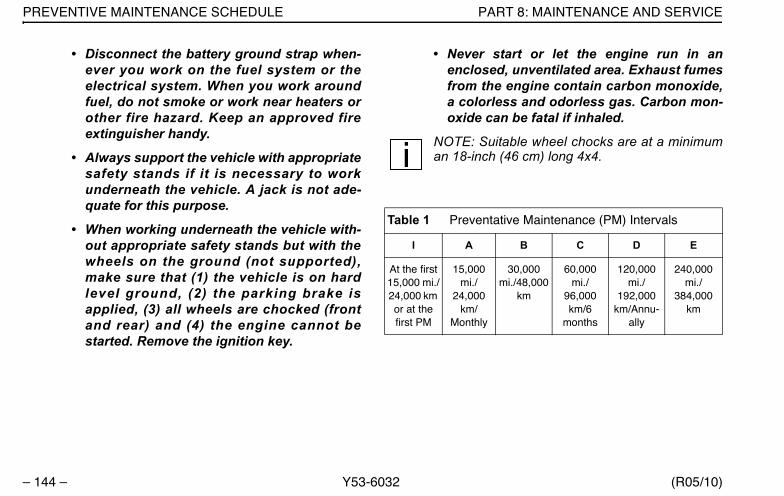
PREVENTIVE MAINTENANCE SCHEDULE PART 8: MAINTENANCE AND SERVICE
– 144 – Y53-6032 (R05/10)
• Disconnect the battery ground strap when-ever you work on the fuel system or theelectrical system. When you work aroundfuel, do not smoke or work near heaters orother fire hazard. Keep an approved fireextinguisher handy.
• Always support the vehicle with appropriatesafety stands if it is necessary to workunderneath the vehicle. A jack is not ade-quate for this purpose.
• When working underneath the vehicle with-out appropriate safety stands but with thewheels on the ground (not supported),make sure that (1) the vehicle is on hardlevel ground, (2) the parking brake isapplied, (3) all wheels are chocked (frontand rear) and (4) the engine cannot bestarted. Remove the ignition key.
• Never start or let the engine run in anenclosed, unventilated area. Exhaust fumesfrom the engine contain carbon monoxide,a colorless and odorless gas. Carbon mon-oxide can be fatal if inhaled.
NOTE: Suitable wheel chocks are at a minimuman 18-inch (46 cm) long 4x4.
Table 1 Preventative Maintenance (PM) Intervals
I A B C D E
At the first15,000 mi./24,000 km or at the first PM
15,000 mi./
24,000 km/
Monthly
30,000 mi./48,000
km
60,000 mi./
96,000 km/6
months
120,000 mi./
192,000 km/Annu-
ally
240,000 mi./
384,000 km
Y53-6032.book Page 144 Monday, May 24, 2010 3:37 PM
PART 8: MAINTENANCE AND SERVICE PREVENTIVE MAINTENANCE SCHEDULE
(R05/10) Y53-6032 – 145 –
NOTES:
• Where questions or discrepancies developbetween these recommendations and compo-nent supplier recommendations, consult thesupplier for specific recommendations.
• Maintenance requirements of specific voca-tional configurations will dictate whether theintervals used are determined based on mile-age, time in service, hours operating, etc.
• These maintenance practices and intervals areintended as additional requirements and arenot to replace, in whole or in part, the pretripinspection requirements of the CommercialDriver’s License (CDL) as established in theFederal Commercial Motor Vehicle Safety Actof 1986.
If you operate your vehicle off-highway or in very heavy-duty applications such as mining, logging, or earth mov-ing, you will need to perform maintenance checks and ser-
vices more frequently. The charts on the following pagesshow the maintenance intervals for recommended main-tenance practices.
NOTES:
• Engine lubricating oil change intervals aren’tlisted here. Refer to your engine’s operatingmanual for recommendations. For specificinformation on maintenance procedures, con-sult your vehicle maintenance manual.
• The initial fill of drive axle lubricant must bechanged before the end of the first scheduledmaintenance interval. Refer to the informationon page 169 before you put a new vehicle intoservice.
• The initial fill of lubricant in manual transmis-sions must be changed before the end of thefirst maintenance interval. See page 165 forspecific information.
Y53-6032.book Page 145 Monday, May 24, 2010 3:37 PM
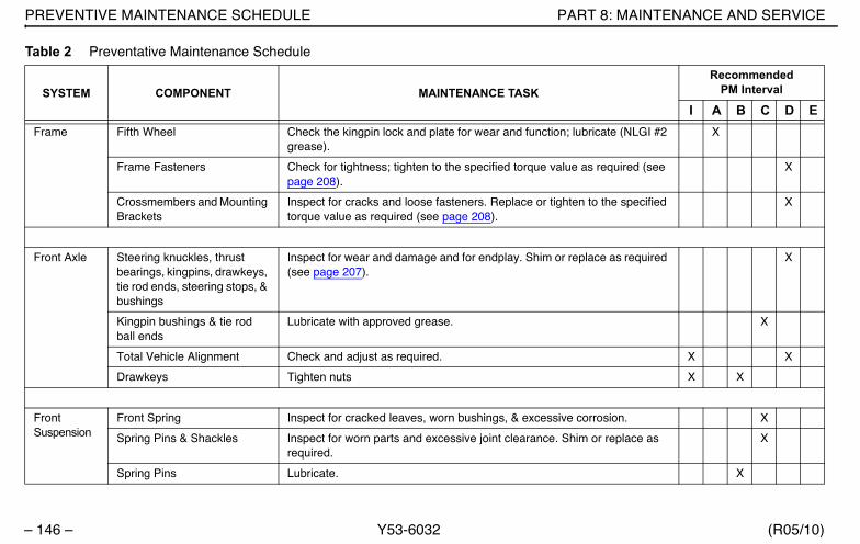
PREVENTIVE MAINTENANCE SCHEDULE PART 8: MAINTENANCE AND SERVICE
– 146 – Y53-6032 (R05/10)
Table 2 Preventative Maintenance Schedule
SYSTEM COMPONENT MAINTENANCE TASKRecommended
PM Interval
I A B C D EFrame Fifth Wheel Check the kingpin lock and plate for wear and function; lubricate (NLGI #2
grease).X
Frame Fasteners Check for tightness; tighten to the specified torque value as required (see page 208).
X
Crossmembers and Mounting Brackets
Inspect for cracks and loose fasteners. Replace or tighten to the specified torque value as required (see page 208).
X
Front Axle Steering knuckles, thrust bearings, kingpins, drawkeys, tie rod ends, steering stops, & bushings
Inspect for wear and damage and for endplay. Shim or replace as required (see page 207).
X
Kingpin bushings & tie rod ball ends
Lubricate with approved grease. X
Total Vehicle Alignment Check and adjust as required. X X
Drawkeys Tighten nuts X X
FrontSuspension
Front Spring Inspect for cracked leaves, worn bushings, & excessive corrosion. X
Spring Pins & Shackles Inspect for worn parts and excessive joint clearance. Shim or replace as required.
X
Spring Pins Lubricate. X
Y53-6032.book Page 146 Monday, May 24, 2010 3:37 PM
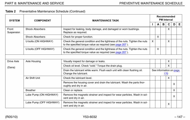
PART 8: MAINTENANCE AND SERVICE PREVENTIVE MAINTENANCE SCHEDULE
(R05/10) Y53-6032 – 147 –
FrontSuspension
Shock Absorbers Inspect for leaking, body damage, and damaged or worn bushings. Replace as required.
X
Shock Absorbers Check for proper function. X
U-bolts (ON HIGHWAY) Check the general condition and the tightness of the nuts. Tighten the nuts to the specified torque value as required (see page 207 ).
X X
U-bolts (OFF HIGHWAY) Check the general condition and the tightness of the nuts. Tighten the nuts to the specified torque value as required (see page 207 ).
X
Drive Axle
(Dana)
Axle Housing Visually inspect for damage or leaks. X
Check oil level. Check “cold.” Torque the drain plug. X
Drain the lubricant while warm. Flush each unit with clean flushing oil. Change the lubricant.
See information on page 170
Air Shift Unit Check the lubricant level. X
Remove the housing cover and drain the lubricant. Wash the parts thor-oughly and dry in air.
X
Breather Clean or replace. X
Lube Pump (ON HIGHWAY) Remove the magnetic strainer and inspect for wear particles. Wash in sol-vent and dry in air.
X
Lube Pump (OFF HIGHWAY) Remove the magnetic strainer and inspect for wear particles. Wash in sol-vent and dry in air.
X
Table 2 Preventative Maintenance Schedule (Continued)
SYSTEM COMPONENT MAINTENANCE TASKRecommended
PM Interval
I A B C D E
Y53-6032.book Page 147 Monday, May 24, 2010 3:37 PM

PREVENTIVE MAINTENANCE SCHEDULE PART 8: MAINTENANCE AND SERVICE
– 148 – Y53-6032 (R05/10)
Drive Axle
(Dana)
Lube Filter (ON HIGHWAY) Change. X
Lube Filter (OFF HIGHWAY) Change. X
Magnetic drain plug and breather (ON HIGHWAY)
Clean or replace.X
Magnetic drain plug and breather (OFF HIGHWAY)
Clean or replace.X
Drive Axle
(Meritor)
Axle Housing Check the “cold” fill level at the differential carrier plug for a pinion angle of less than 7 degrees, or at the axle bowl plug for a pinion angle of greater than 7 degrees. Tighten the plug to 35 - 50 Lb. ft. (47 - 68 N.m.)
X
Axle Housing Visually inspect for damage or leaks. X
Axle Housing Drain and replace the lubricant. See information on page 169
Lubricant filter Change the filter. X
Breather Check the operation. If the cap doesn’t rotate freely, replace. X
Input shaft & pinion shaft Check and adjust the endplay. X
Axle shaft Tighten the rear axle flange nuts to the specified torque value. X
Interaxle differential Check the operation. X
Table 2 Preventative Maintenance Schedule (Continued)
SYSTEM COMPONENT MAINTENANCE TASKRecommended
PM Interval
I A B C D E
Y53-6032.book Page 148 Monday, May 24, 2010 3:37 PM

PART 8: MAINTENANCE AND SERVICE PREVENTIVE MAINTENANCE SCHEDULE
(R05/10) Y53-6032 – 149 –
RearSuspension
U-bolts Check the torque. Tighten to specified torque value as required (see page 207).
X X
Frame & crossmember bolts Check the torque. Tighten to specified torque value as required (see page 208).
X
Mounting brackets and fas-teners
Check the condition and the fastener torque. Tighten to the specified torque value as required (see page 208).
X X
Drum Brakes(All)
Slack adjusters Check the push rod travel and check the control arm for cracks. Adjust at reline (see page 173).
X
Lubricate (NLGI #2 grease). X
Brake camshaft bearing Lubricate (NLGI #2 grease). X
Check for excessive cam shaft play in the axial and radial directions. Max allowable play is 0.003”.
X
Brake treadle valve Clean the area around the treadle, boot, and mounting plate. Check the pivot and mounting plate for integrity. Check the plunger boot for cracks. Lubricate roller pin, pivot pin, and plunger (NLGI #2 grease).
X
Brake air system Check air lines and fittings for leaks (see page 173). Adjust routing as required to reduce chafing. Check tank mounting and condition.
X
Brake air system Clean or replace the inline filters. X
Brake lining Inspect; replace as required. X
Table 2 Preventative Maintenance Schedule (Continued)
SYSTEM COMPONENT MAINTENANCE TASKRecommended
PM Interval
I A B C D E
Y53-6032.book Page 149 Monday, May 24, 2010 3:37 PM
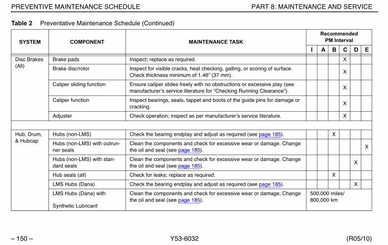
PREVENTIVE MAINTENANCE SCHEDULE PART 8: MAINTENANCE AND SERVICE
– 150 – Y53-6032 (R05/10)
Disc Brakes (All)
Brake pads Inspect; replace as required. X
Brake disc/rotor Inspect for visible cracks, heat checking, galling, or scoring of surface. Check thickness minimum of 1.46” (37 mm).
X
Caliper sliding function Ensure caliper slides freely with no obstructions or excessive play (see manufacturer’s service literature for “Checking Running Clearance”).
X
Caliper function Inspect bearings, seals, tappet and boots of the guide pins for damage or cracking.
X
Adjuster Check operation; inspect as per manufacturer’s service literature. X
Hub, Drum, & Hubcap
Hubs (non-LMS) Check the bearing endplay and adjust as required (see page 185). X
Hubs (non-LMS) with outrun-ner seals
Clean the components and check for excessive wear or damage. Change the oil and seal (see page 185).
X
Hubs (non-LMS) with stan-dard seals
Clean the components and check for excessive wear or damage. Change the oil and seal (see page 185).
X
Hub seals (all) Check for leaks; replace as required. X
LMS Hubs (Dana) Check the bearing endplay and adjust as required (see page 185). X
LMS Hubs (Dana) with
Synthetic Lubricant
Clean the components and check for excessive wear or damage. Change the oil and seal (see page 185).
500,000 miles/800,000 km
Table 2 Preventative Maintenance Schedule (Continued)
SYSTEM COMPONENT MAINTENANCE TASKRecommended
PM Interval
I A B C D E
Y53-6032.book Page 150 Monday, May 24, 2010 3:37 PM
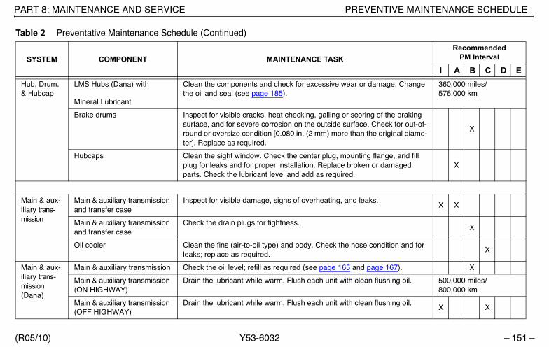
PART 8: MAINTENANCE AND SERVICE PREVENTIVE MAINTENANCE SCHEDULE
(R05/10) Y53-6032 – 151 –
Hub, Drum, & Hubcap
LMS Hubs (Dana) with
Mineral Lubricant
Clean the components and check for excessive wear or damage. Change the oil and seal (see page 185).
360,000 miles/576,000 km
Brake drums Inspect for visible cracks, heat checking, galling or scoring of the braking surface, and for severe corrosion on the outside surface. Check for out-of-round or oversize condition [0.080 in. (2 mm) more than the original diame-ter]. Replace as required.
X
Hubcaps Clean the sight window. Check the center plug, mounting flange, and fill plug for leaks and for proper installation. Replace broken or damaged parts. Check the lubricant level and add as required.
X
Main & aux-iliary trans-mission
Main & auxiliary transmission and transfer case
Inspect for visible damage, signs of overheating, and leaks.X X
Main & auxiliary transmission and transfer case
Check the drain plugs for tightness.X
Oil cooler Clean the fins (air-to-oil type) and body. Check the hose condition and for leaks; replace as required.
X
Main & aux-iliary trans-mission (Dana)
Main & auxiliary transmission Check the oil level; refill as required (see page 165 and page 167). X
Main & auxiliary transmission (ON HIGHWAY)
Drain the lubricant while warm. Flush each unit with clean flushing oil. 500,000 miles/800,000 km
Main & auxiliary transmission (OFF HIGHWAY)
Drain the lubricant while warm. Flush each unit with clean flushing oil.X X
Table 2 Preventative Maintenance Schedule (Continued)
SYSTEM COMPONENT MAINTENANCE TASKRecommended
PM Interval
I A B C D E
Y53-6032.book Page 151 Monday, May 24, 2010 3:37 PM
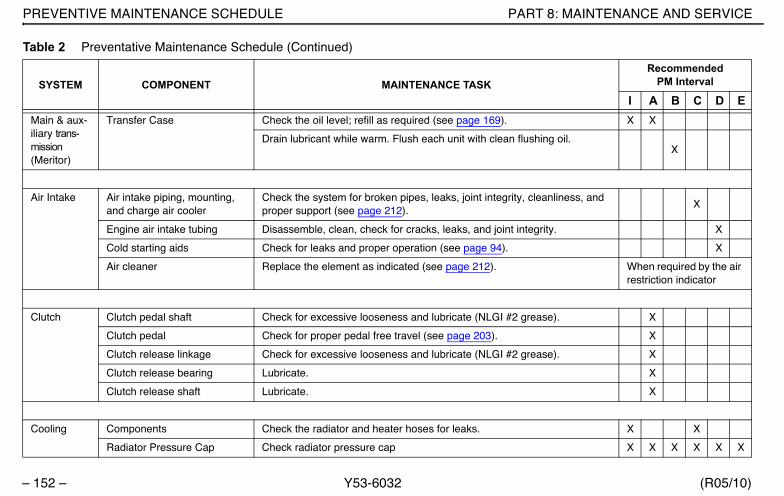
PREVENTIVE MAINTENANCE SCHEDULE PART 8: MAINTENANCE AND SERVICE
– 152 – Y53-6032 (R05/10)
Main & aux-iliary trans-mission(Meritor)
Transfer Case Check the oil level; refill as required (see page 169). X X
Drain lubricant while warm. Flush each unit with clean flushing oil.X
Air Intake Air intake piping, mounting, and charge air cooler
Check the system for broken pipes, leaks, joint integrity, cleanliness, and proper support (see page 212).
X
Engine air intake tubing Disassemble, clean, check for cracks, leaks, and joint integrity. X
Cold starting aids Check for leaks and proper operation (see page 94). X
Air cleaner Replace the element as indicated (see page 212). When required by the air restriction indicator
Clutch Clutch pedal shaft Check for excessive looseness and lubricate (NLGI #2 grease). X
Clutch pedal Check for proper pedal free travel (see page 203). X
Clutch release linkage Check for excessive looseness and lubricate (NLGI #2 grease). X
Clutch release bearing Lubricate. X
Clutch release shaft Lubricate. X
Cooling Components Check the radiator and heater hoses for leaks. X X
Radiator Pressure Cap Check radiator pressure cap X X X X X X
Table 2 Preventative Maintenance Schedule (Continued)
SYSTEM COMPONENT MAINTENANCE TASKRecommended
PM Interval
I A B C D E
Y53-6032.book Page 152 Monday, May 24, 2010 3:37 PM
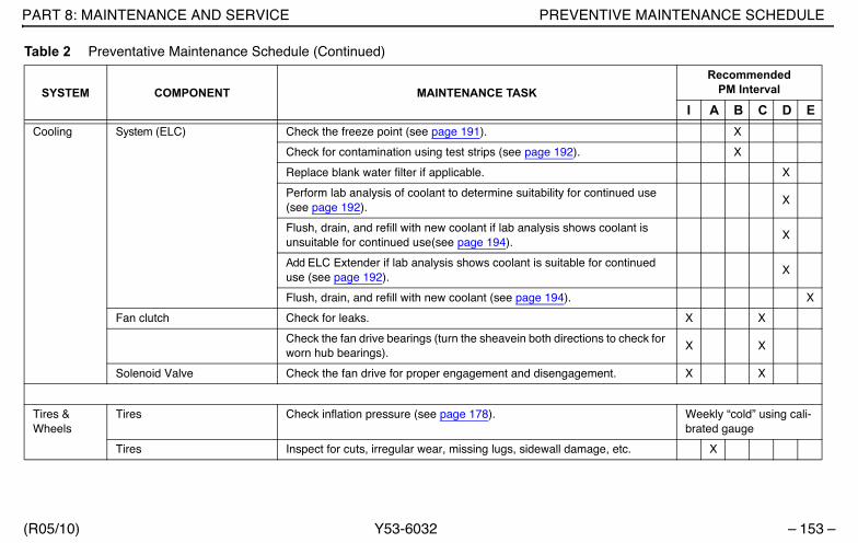
PART 8: MAINTENANCE AND SERVICE PREVENTIVE MAINTENANCE SCHEDULE
(R05/10) Y53-6032 – 153 –
Cooling System (ELC) Check the freeze point (see page 191). X
Check for contamination using test strips (see page 192). X
Replace blank water filter if applicable. X
Perform lab analysis of coolant to determine suitability for continued use (see page 192).
X
Flush, drain, and refill with new coolant if lab analysis shows coolant is unsuitable for continued use(see page 194).
X
Add ELC Extender if lab analysis shows coolant is suitable for continued use (see page 192).
X
Flush, drain, and refill with new coolant (see page 194). X
Fan clutch Check for leaks. X X
Check the fan drive bearings (turn the sheavein both directions to check for worn hub bearings).
X X
Solenoid Valve Check the fan drive for proper engagement and disengagement. X X
Tires & Wheels
Tires Check inflation pressure (see page 178). Weekly “cold” using cali-brated gauge
Tires Inspect for cuts, irregular wear, missing lugs, sidewall damage, etc. X
Table 2 Preventative Maintenance Schedule (Continued)
SYSTEM COMPONENT MAINTENANCE TASKRecommended
PM Interval
I A B C D E
Y53-6032.book Page 153 Monday, May 24, 2010 3:37 PM

PREVENTIVE MAINTENANCE SCHEDULE PART 8: MAINTENANCE AND SERVICE
– 154 – Y53-6032 (R05/10)
Tires & Wheels
Disc wheels Inspect the wheel disc for any cracks or surface irregularities. Inspect the rim edge and bead seat area for damage. Replace any damaged wheels - DO NOT ATTEMPT TO REPAIR.
X
Demountable rims Inspect the mounting ring, rim gutter, side ring, and lock ring for damage; replace as required.
X
Wheel nuts and studs Check the tightness of the fasteners and tighten the fasteners to the speci-fied torque as required (see page 185).
X
Wheel nuts and studs Inspect for damaged hex corners, stripped or damaged threads, and excessive corrosion; clean or replace as required.
X
Power Steering
Reservoir Check the fluid level (see page 171). X
Reservoir (ON HIGHWAY) Drain, replace the filter, and refill (see page 171). X X
Reservoir (OFF HIGHWAY) Drain, replace the filter, and refill (see page 171). X X
Steering gear Check the lash of the sector shaft; adjust as required. X
Steering gear Grease the trunnion bearing (EP NLGI #2 lithium-based, moly-filled, HD grease).
X
Steering gear Grease the input shaft seal (EP NLGI #2 lithium-based, moly-filled, HD grease).
X
Power assist cylinder Lubricate the ball joints. Inspect for leaking rod seals, damaged ball joint boots, and damage to cylinder rod or barrel.
X
Hoses and tubes Check for leaks and chafing. X
Table 2 Preventative Maintenance Schedule (Continued)
SYSTEM COMPONENT MAINTENANCE TASKRecommended
PM Interval
I A B C D E
Y53-6032.book Page 154 Monday, May 24, 2010 3:37 PM

PART 8: MAINTENANCE AND SERVICE PREVENTIVE MAINTENANCE SCHEDULE
(R05/10) Y53-6032 – 155 –
Power Steering
Steering linkage Check all joints for excessive lash; replace as required (see page 207). X
Draglink tube clamp and ball socket
Check the torque; tighten to specified torque value as required.X X
Pitman arm clamp bolt and nut
Check the torque; tighten to specified torque value as required.X X
Steering intermediate shaft Check the torque on the pinch bolt and nut. X X
Steering intermediate shaft U-joints (ON HIGHWAY)
Lubricate [EP NLGI #2 HD grease, +325° F to -10° F (+163° C to-23° C) range].
X X
Steering intermediate shaft U-joints (OFF HIGHWAY or CITY DELIVERY)
Lubricate [EP NLGI #2 HD grease, +325° F to -10° F (+163° C to-23° C) range]. X X
Draglink and tie rod arm ball sockets (ON HIGHWAY)
Lubricate (EP NLGI #2 lithium-based, moly-filled, HD grease).X X
Steering intermediate shaft U-joints (OFF HIGHWAY or CITY DELIVERY)
Lubricate (EP NLGI #2 lithium-based, moly-filled, HD grease).X X
Fuel & Tanks
Fuel tanks Inspect tanks, brackets, hoses, and fittings for correct location, tightness, abrasion damage, and leaks; repair or replace as required.
X
Fuel tank breathers Check for proper function; clean the drain hoses. X
Table 2 Preventative Maintenance Schedule (Continued)
SYSTEM COMPONENT MAINTENANCE TASKRecommended
PM Interval
I A B C D E
Y53-6032.book Page 155 Monday, May 24, 2010 3:37 PM

PREVENTIVE MAINTENANCE SCHEDULE PART 8: MAINTENANCE AND SERVICE
– 156 – Y53-6032 (R05/10)
Fuel & Tanks
Fuel tank straps Tighten to proper torque value of 45 - 70 Lb. ft. (61 - 95 N.m.); *check annu-ally once strap tension reaches a steady state; i.e., after 2 - 3 retorquings, the measured torque is the same as previous reading.
X X *
Driveshafts Models 1610-1810 & SPL-90 Lubricate slip member & U-joints X X
Model SPL-100 Lubricate slip member & U-joints X
Models SPL-140/140HD/170/170HD/250/250HD
Lubricate slip member & U-jointsX
Models SPL-140XL/170XL/250XL (ON HIGHWAY & LINE HAUL)
Lubricate slip member & U-joints 360,000 miles/576,000 km/every 3 years
Models SPL-140XL/170XL/250XL (OFF HIGHWAY & CITY)
Lubricate slip member & U-jointsX
Battery Battery cables Check the condition of the cables, cushion clamps, and routing. Replace a cushion clamp if the rubber has deteriorated. Repair or tighten terminals, and secure cables to prevent chafing. Replace damaged cables (cuts, cracks, or excessive wear) (see page 195).
X X
Batteries Check for cracks and damage, electrolyte level, condition of terminals, and tightness of holddowns (see page 195).
X
Table 2 Preventative Maintenance Schedule (Continued)
SYSTEM COMPONENT MAINTENANCE TASKRecommended
PM Interval
I A B C D E
Y53-6032.book Page 156 Monday, May 24, 2010 3:37 PM
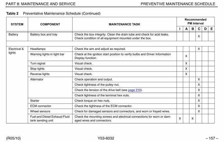
PART 8: MAINTENANCE AND SERVICE PREVENTIVE MAINTENANCE SCHEDULE
(R05/10) Y53-6032 – 157 –
Battery Battery box and tray Check the box integrity. Clean the drain tube and check for acid leaks. Check condition of all equipment mounted under the box.
X
Electrical & lights
Headlamps Check the aim and adjust as required. X
Warning lights in light bar Check at the ignition start position to verify bulbs and Driver Information Display function.
X
Turn signal Visual check. X
Stop lights Visual check. X
Reverse lights Visual check. X
Alternator Check operation and output. X
Check tightness of the pulley nut. X
Check the tension of the drive belt (see page 210). X
Check tightness of the terminal hex nuts. X
Starter Check torque on hex nuts. X
ECM connector Check the tightness of the ECM connector. X
Wheel sensors Check for damaged sensors and connectors, and worn or frayed wires. X
Fuel and Diesel Exhaust Fluid tank sending unit
Check the mounting screws and electrical connections for worn or dam-aged wires and connectors.
X X
Table 2 Preventative Maintenance Schedule (Continued)
SYSTEM COMPONENT MAINTENANCE TASKRecommended
PM Interval
I A B C D E
Y53-6032.book Page 157 Monday, May 24, 2010 3:37 PM

PREVENTIVE MAINTENANCE SCHEDULE PART 8: MAINTENANCE AND SERVICE
– 158 – Y53-6032 (R05/10)
Electrical & lights
Power supply harnesses (engine, transmission, etc.)
Check for worn or damaged insulation, corroded terminals, frayed wires, and oil or fluid leaks on the connectors or wiring.
X
Power supply harnesses (engine, transmission, etc.)
Wash to remove excess grease.X
Cab struc-ture, doors, & hoods
Hood Lubricate the lower hood pivot (only if lube fittings are present). X
Hinges and latch Lubricate with silicone spray. X
Body & cab holddown bolts Check the condition and tightness. X
Heating & Air Condi-tioning
Air conditioner Operate the system. (NOTE: The air conditioning system is active when the Defrost/Defog mode is selected.)
X
Heater & air conditioner Perform the checks listed on page 215. X
Full operational and diagnostic check. X
Cab air filter Clean; replace after a maximum of three cleanings. X
Condenser Clear any debris from the front of the condenser. X
Aftertreat-ment Sys-tem
System Check for leaks and proper support (see page 213). X
Flexible pipe Replace the main and anciliary exhaust flexible pipe. 150,000 mi/241,401 Km
Table 2 Preventative Maintenance Schedule (Continued)
SYSTEM COMPONENT MAINTENANCE TASKRecommended
PM Interval
I A B C D E
Y53-6032.book Page 158 Monday, May 24, 2010 3:37 PM
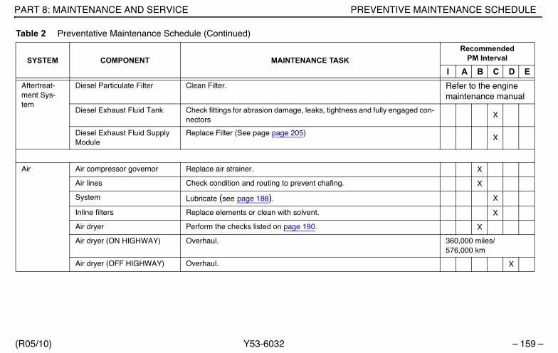
PART 8: MAINTENANCE AND SERVICE PREVENTIVE MAINTENANCE SCHEDULE
(R05/10) Y53-6032 – 159 –
Aftertreat-ment Sys-tem
Diesel Particulate Filter Clean Filter. Refer to the engine maintenance manual
Diesel Exhaust Fluid Tank Check fittings for abrasion damage, leaks, tightness and fully engaged con-nectors
X
Diesel Exhaust Fluid Supply Module
Replace Filter (See page page 205)X
Air Air compressor governor Replace air strainer. X
Air lines Check condition and routing to prevent chafing. X
System Lubricate (see page 188). X
Inline filters Replace elements or clean with solvent. X
Air dryer Perform the checks listed on page 190. X
Air dryer (ON HIGHWAY) Overhaul. 360,000 miles/576,000 km
Air dryer (OFF HIGHWAY) Overhaul. X
Table 2 Preventative Maintenance Schedule (Continued)
SYSTEM COMPONENT MAINTENANCE TASKRecommended
PM Interval
I A B C D E
Y53-6032.book Page 159 Monday, May 24, 2010 3:37 PM

PREVENTIVE MAINTENANCE SCHEDULE PART 8: MAINTENANCE AND SERVICE
– 160 – Y53-6032 (R05/10)
Engine Basic Engine The maintenance and service interval recommendations for the specific engine are the maintenance requirements specified in the engine manufac-turer’s Operations and Maintenance Manual included with the vehicle. Strict adherence to these recommendations is required to maintain war-ranty coverage. The maintenance and service interval recommendations for the engines vary significantly, depending on the manufacturer and the model of the engine. As a minimum, perform the operations listed below:
Table 2 Preventative Maintenance Schedule (Continued)
SYSTEM COMPONENT MAINTENANCE TASKRecommended
PM Interval
I A B C D E
Y53-6032.book Page 160 Monday, May 24, 2010 3:37 PM

PART 8: MAINTENANCE AND SERVICE PREVENTIVE MAINTENANCE SCHEDULE
(R05/10) Y53-6032 – 161 –
Lubricant SpecificationsWARNING! Handle lubricants carefully. Vehiclelubricants (oil and grease) can be poisonous andcause death, injury or sickness. They can alsodamage the paint on the vehicle.
In this section you will find the basic information you need todo the routine lubrication your vehicle requires. Of course youwill want to schedule service more frequently if you are oper-ating under severe conditions such as extreme heat or cold,with very heavy loads, off-road, etc. For any special servicerequirements, consult your service manuals and your lubri-cant supplier. And please remember: one key to keeping yourtruck running at top economy and in prolonging its life isproper lubrication servicing. Neglecting this essential aspectof vehicle care can cost time and money in the long run.
CAUTION: Do not mix different types of lubri-cants. Mixing lubricants (oil and grease) of differ-ent brands or types could damage vehiclecomponents; therefore, drain (or remove) oldlubricants from the unit before refilling it.
EngineNOTE: The engine in this vehicle may comply withEPA emission standards. Consult the engine manu-facturer’s manual for changed lubrication and main-tenance requirements.
Proper engine lubrication depends on the outside tempera-tures where you will be driving. Use the oil recommended forthe conditions you are most likely to be facing. You will find acomplete engine lubrication service guide in the EngineOperation Manual that came with your vehicle. There, theengine manufacturer explains more fully all the maintenanceoperations that you and a qualified service mechanic need toperform on your engine.
WARNING! Exhaust fumes from the engine con-tain carbon monoxide, a colorless and odorlessgas. Do not breathe the engine exhaust gas. Apoorly maintained, damaged or corroded exhaustsystem can allow carbon monoxide to enter thecab or sleeper. Entry of carbon monoxide into thecab is also possible from other vehicles nearby.Failure to properly maintain your vehicle couldcause carbon monoxide to enter the cab/sleeperand cause death or serious illness.
Y53-6032.book Page 161 Monday, May 24, 2010 3:37 PM

PREVENTIVE MAINTENANCE SCHEDULE PART 8: MAINTENANCE AND SERVICE
– 162 – Y53-6032 (R05/10)
WARNING! Never idle your vehicle for prolongedperiods of time if you sense that exhaust fumesare entering the cab or sleeper. Investigate thecause of the fumes and correct it as soon as pos-sible. If the vehicle must be driven under theseconditions, drive only with the windows slightlyopen. Failure to repair the source of the exhaustfumes may lead to death or personal injury.
NOTES:Keep the engine exhaust system and thevehicle’s cab/sleeper ventilation system properlymaintained. It is recommended that the vehicle’sexhaust system and cab/sleeper be inspected
• By a competent technician every 15,000 miles/24,000 km.
• Whenever a change is noticed in the sound of theexhaust system.
• Whenever the exhaust system, underbody, cab orsleeper is damaged.
NOTE: Use only exact replacement components inexhaust systems. Certain components contain inte-gral catalytic converters essential for compliance withEPA emission standards. Using noncompliant com-ponents as a replacement could violate these stan-dards and also void the emission system’s warranty.
WARNING! Hot engine oil can be dangerous. Youcould be seriously burned. Let the engine oil cooldown before changing it.
Y53-6032.book Page 162 Monday, May 24, 2010 3:37 PM
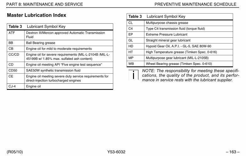
PART 8: MAINTENANCE AND SERVICE PREVENTIVE MAINTENANCE SCHEDULE
(R05/10) Y53-6032 – 163 –
Master Lubrication Index
NOTE: The responsibility for meeting these specifi-cations, the quality of the product, and its perfor-mance in service rests with the lubricant supplier.
Table 3 Lubricant Symbol Key
ATF Dextron III/Mercon approved Automatic Transmission Fluid
BB Ball Bearing grease
CB Engine oil for mild to moderate requirements
CC/CD Engine oil for severe requirements (MIL-L-2104B /MIL-L-45199B w/ 1.85% max. sulfated ash content)
CD Engine oil meeting API “Five engine test sequence”
CD50 SAE50W synthetic transmission fluid
CE Engine oil meeting severe duty service requirements for direct-injection turbocharged engines
CJ-4 Engine oil
CL Multipurpose chassis grease
C4 Type C4 transmission fluid (torque fluid)
EP Extreme Pressure Lubricant
GL Straight mineral gear lubricant
HD Hypoid Gear Oil, A.P.I. - GL-5, SAE 80W-90
HT High Temperature grease (Timken Spec. 0-616)
MP Multipurpose gear lubricant (MIL-L-2105B)
WB Wheel Bearing grease (Timken Spec. 0-610)
Table 3 Lubricant Symbol Key
Y53-6032.book Page 163 Monday, May 24, 2010 3:37 PM

PREVENTIVE MAINTENANCE SCHEDULE PART 8: MAINTENANCE AND SERVICE
– 164 – Y53-6032 (R05/10)
Table 4 Component Lubrication Index
Universal Joints EP
Drive Shaft Splines CL
Wheel Bearings (driven hubs) HD
Wheel Bearings (nondriven hubs) CD50
Wheel Bearings (all grease-lubricated hubs) WB
Steering Column CL
Alternator Bearing BB*
Fan Hub BB*
Power Steering Reservoir ATF
Steering Drag Link CL
Steering Knuckles CL
Spring Pins CL
Clutch Release Bearings BB
Brake Shoe Anchor Pins HT
Brake Cam Bearings HT
Slack Adjusters CL
Water Pump BB*
Cab Tilt Hydraulic Reservoir Hydraulic Jack Oil, MIL-L-5056B
Speedometer Cables LubriplateAero or equivalent
*Consult manufacturer or lubricant supplier for special details
Table 4 Component Lubrication Index (Continued)
Y53-6032.book Page 164 Monday, May 24, 2010 3:37 PM

PART 8: MAINTENANCE AND SERVICE PREVENTIVE MAINTENANCE SCHEDULE
(R05/10) Y53-6032 – 165 –
Fuller Transmission LubricationFuller transmissions are designed so that the internal partsoperate in a bath of oil circulated by the motion of gearsand shafts. Grey iron parts have built-in channels whereneeded to help lubricate bearings and shafts. All parts willbe amply lubricated if these procedures are closely fol-lowed:
1. Maintain oil level; check it regularly.
2. Change oil regularly.
3. Use the correct grade and type of oil.
4. Buy oil from a reputable dealer.
Lubrication Change and Inspection
Off-Highway Use
Refer to the Eaton Fuller transmission manual for servic-ing information.
Highway Use
• Refer to the Eaton Fuller transmission manual for ser-vicing information.
• Refer to the oil change vs. temperature chart that fol-lows for special oil change information. The “intermit-tent peak temperature” is the maximum temperatureobserved for a short time in a fully loaded vehicle per-forming normally.
02942
Y53-6032.book Page 165 Monday, May 24, 2010 3:37 PM

PREVENTIVE MAINTENANCE SCHEDULE PART 8: MAINTENANCE AND SERVICE
– 166 – Y53-6032 (R05/10)
CAUTION: Exceeding the recommended oilchange intervals may be harmful to the life ofthe transmission and the transmission oilcooler.
Recommended Lubricants
Table 5 Recommended Lubricants
Type Grade (SAE) Ambient Temperature
Heavy Duty Engine Oil MIL-L-2104B, C, or D;
50 Above 10° F (-12° C)
API - SF, or API-CD (Previous API des-ignations are acceptable)
40 Above 10° F (-12° C
30 Below 10° F (-12° C)
Mineral gear oil with rust and oxida-tion inhibitor API-GL-1
90 Above 10° F (-12° C)
80W Below 10° F (-12° C)
Synthetic Lubri-cant*
50 All
* See your Peterbilt dealer for approved brands.
Y53-6032.book Page 166 Monday, May 24, 2010 3:37 PM
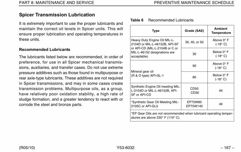
PART 8: MAINTENANCE AND SERVICE PREVENTIVE MAINTENANCE SCHEDULE
(R05/10) Y53-6032 – 167 –
Spicer Transmission LubricationIt is extremely important to use the proper lubricants andmaintain the correct oil levels in Spicer units. This willensure proper lubrication and operating temperatures inthese units.
Recommended Lubricants
The lubricants listed below are recommended, in order ofpreference, for use in all Spicer mechanical transmis-sions, auxiliaries, and transfer cases. Do not use extremepressure additives such as those found in multipurpose orrear axle-type lubricants. These additives are not requiredin Spicer transmissions, and may in some cases createtransmission problems. Multipurpose oils, as a group,have relatively poor oxidation stability, a high rate ofsludge formation, and a greater tendency to react with orcorrode the steel and bronze parts.
Table 6 Recommended Lubricants
Type Grade (SAE) Ambient Temperature
Heavy Duty Engine Oil MIL-L-2104D or MIL-L-46152B, API-SF or API-CD (MIL-L-2104B or C or MIL-L-46152 designations are acceptable)
30, 40, or 50Above 0° F
(-18° C)
30Below 0° F (-18° C)
Mineral gear oil (R & O type) API-GL-1
90Above 0° F
(-18° C)
80Below 0° F
(-18° C)
Synthetic Engine Oil meeting MIL-L-2104D or MIL-L-46152B, API-SF or API-CD
CD50 CD30
All
*Synthetic Gear Oil Meeting MIL-2105C or API-GL5
EP75W90 EP75W140
All
*EP Gear Oils are not recommended when lubricant operating temper-atures are above 230° F (110° C).
Y53-6032.book Page 167 Monday, May 24, 2010 3:37 PM

PREVENTIVE MAINTENANCE SCHEDULE PART 8: MAINTENANCE AND SERVICE
– 168 – Y53-6032 (R05/10)
Oil Changes
CAUTION: When adding oil, types and brandsof oil should not be intermixed because ofpossible incompat ibi l i ty, which coulddecrease the effectiveness of the lubricationor cause component failure.
An initial oil change and flush should be performed afterthe transmission has been placed in actual service. Thischange should be made any time after 3000 miles (4800km) but never longer than 5000 miles (8000 km) of over-the-road service. In off-highway use, the change shouldbe made after 24 hours but before 100 hours of servicehave elapsed.
Refilling
Remove all dirt around filler plug. Refill with new oil of thegrade recommended for the existing season and prevail-ing service. Fill to the bottom of the level testing plug posi-tioned on the side of the transmission. Do not overfill thetransmission. Overfilling usually results in oil breakdowndue to excessive heat and aeration from the churningaction of the gears. Early breakdown of the oil will result inheavy varnish and sludge deposits that plug up oil portsand build up on the splines and bearings. Overflow of oilcan also escape onto clutch or parking brakes. When add-ing oil, do not mix different types of oil.
Y53-6032.book Page 168 Monday, May 24, 2010 3:37 PM
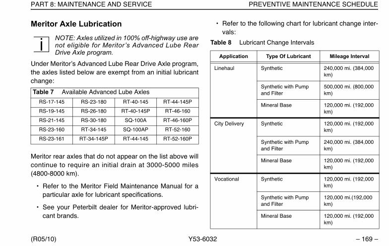
PART 8: MAINTENANCE AND SERVICE PREVENTIVE MAINTENANCE SCHEDULE
(R05/10) Y53-6032 – 169 –
Meritor Axle LubricationNOTE: Axles utilized in 100% off-highway use arenot eligible for Meritor’s Advanced Lube RearDrive Axle program.
Under Meritor’s Advanced Lube Rear Drive Axle program,the axles listed below are exempt from an initial lubricantchange:
Meritor rear axles that do not appear on the list above willcontinue to require an initial drain at 3000-5000 miles(4800-8000 km).
• Refer to the Meritor Field Maintenance Manual for aparticular axle for lubricant specifications.
• See your Peterbilt dealer for Meritor-approved lubri-cant brands.
• Refer to the following chart for lubricant change inter-vals:
Table 7 Available Advanced Lube Axles
RS-17-145 RS-23-180 RT-40-145 RT-44-145P
RS-19-145 RS-26-180 RT-40-145P RT-46-160
RS-21-145 RS-30-180 SQ-100A RT-46-160P
RS-23-160 RT-34-145 SQ-100AP RT-52-160
RS-23-161 RT-34-145P RT-44-145 RT-52-160P
Table 8 Lubricant Change Intervals
Application Type Of Lubricant Mileage Interval
Linehaul Synthetic 240,000 mi. (384,000 km)
Synthetic with Pump and Filter
500,000 mi. (800,000 km)
Mineral Base 120,000 mi. (192,000 km)
City Delivery Synthetic 120,000 mi. (192,000 km)
Synthetic with Pump and Filter
240,000 mi. (384,000 km)
Mineral Base 120,000 mi. (192,000 km)
Vocational Synthetic 120,000 mi. (192,000 km)
Synthetic with Pump and Filter
120,000 mi.(192,000 km)
Mineral Base 120,000 mi. (192,000 km)
Y53-6032.book Page 169 Monday, May 24, 2010 3:37 PM

PREVENTIVE MAINTENANCE SCHEDULE PART 8: MAINTENANCE AND SERVICE
– 170 – Y53-6032 (R05/10)
• Change the lubricant filter every 120,000 miles(192,000 km). Top off the lubricant level with a similarlubricant.
Eaton/Dana Axle Lubrication• The original mineral-based lubricant must be drained
within 3000-5000 miles (4800-8000 km) on all Eatonaxles. This initial change is very important because itflushes out break-in contaminants that might other-wise cause premature wear.
• No initial drain is required on Eaton axles that are fac-tory filled with an Eaton-approved synthetic lubricant.
• Mineral-based lubes must be drained within the first5000 miles (8000 km) if converting to an Eaton-approved synthetic lube.
• Change the lubricant within the first 5000 miles (8000km) of operation after a carrier head replacement,regardless of the lubricant type.
• Refer to the Eaton Field Maintenance Manual for aparticular axle for lubricant specifications.
• See your Peterbilt dealer for Eaton-approved lubricantbrands.
• Refer to the chart below for lubricant change interval.
Wheel Bearing Lubrication
Oil-lubricated Driven Hubs
Use hypoid oil, A.P.I.-GL-5 SAE 80W-90 or equivalent. Aminimum of 1 quart (921 ml) of oil is required for properlubrication of each drive hub. Add oil through the filler holein the hub; if none, add oil through the differential fillerhole. (Note: Remember to replace vent plug or threadedfiller plug when done.) Allow time for the oil to seep
Table 9 Eaton/Dana Axle Lubricant Change Intervals
Type ofLubricant
On-High-way
Mi.(km)
Maximum Change Interval
On/OffHighway
Severe Ser-vice Mi.(km)
Maximum Change Interval
Mineral-Based 120,000 (192,000)
Yearly 60,000 (96,000)
Yearly
Eaton-Approved Synthetic
240,000 (384,000)
2 Years 120,000 (192,000)
Yearly
Eaton-Approved Synthetic in axle with extended drain interval option
360,000 (576,000)
Y53-6032.book Page 170 Monday, May 24, 2010 3:37 PM
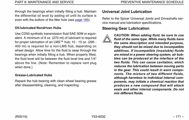
PART 8: MAINTENANCE AND SERVICE PREVENTIVE MAINTENANCE SCHEDULE
(R05/10) Y53-6032 – 171 –
through the bearings when initially filling a hub. Maintainthe differential oil level by adding oil until its surface iseven with the bottom of the filler hole (see page 165).
Oil-lubricated Nondriven Hubs
Use CD50 synthetic transmission fluid SAE 50W or equiv-alent. A minimum of 9 oz. (270 ml) of lubricant is requiredfor proper lubrication of an LMS™ hub; 10 - 13 oz. (295 -400 ml) is required for a non-LMS hub, depending onwheel design. Allow time for the fluid to seep through thebearings when initially filling a hub. When properly filled,the fluid level will lie between the fluid level line and 1/4”above the line. (Note: Remember to replace vent plugwhen done.)
Grease-Lubricated Hubs
Repack the hub bearing with clean wheel bearing greaseafter disassembling, cleaning, and inspecting.
Universal Joint LubricationRefer to the Spicer Universal Joints and Driveshafts ser-vice manual and lubrication specifications.
Steering Gear LubricationCAUTION: When adding fluid, be sure to usefluid of the same type. While many fluids havethe same description and intended purpose,they should not be mixed due to incompatibleadditives. If incompatible (insoluble) fluidsare mixed in a power steering system, air bub-bles can be produced at the interface of thetwo fluids. This can cause cavitation, whichreduces the lubrication between moving partsin the gear. This could result in worn compo-nents. The mixture of two different fluids,although harmless to individual internal com-ponents, may initiate a chemical reaction thatproduces a new compound that will attackseals and other internal components. Do notmix different fluids.
Y53-6032.book Page 171 Monday, May 24, 2010 3:37 PM
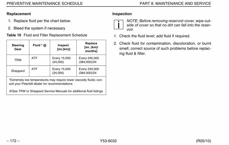
PREVENTIVE MAINTENANCE SCHEDULE PART 8: MAINTENANCE AND SERVICE
– 172 – Y53-6032 (R05/10)
Replacement
1. Replace fluid per the chart below.
2. Bleed the system if necessary.
Inspection
NOTE: Before removing reservoir cover, wipe out-side of cover so that no dirt can fall into the reser-voir.
1. Check the fluid level; add fluid if required.
2. Check fluid for contamination, discoloration, or burntsmell; correct source of such problems before replac-ing fluid & filter.
Table 10 Fluid and Filter Replacement Schedule
Steering Gear
Fluid * @ Inspect [mi.(km)]
Replace [mi. (km)/months]
TRW ATF Every 15,000
(24,000)Every 240,000 (384,000)/24
SheppardATF Every 15,000
(24,000)Every 240,000 (384,000)/24
*Extremely low temperatures may require lower viscosity fluids; con-sult your Peterbilt dealer for recommendations
@See TRW or Sheppard Service Manuals for additional fluid listings
Y53-6032.book Page 172 Monday, May 24, 2010 3:37 PM

PART 8: MAINTENANCE AND SERVICE SERVICING SPECIFIC SYSTEMS AND UNITS
(R05/10) Y53-6032 – 173 –
Servicing Specific Systems And UnitsThis section will help you keep your Peterbilt vehicle ingood running condition. There are a number of checksyou can do, and you may be able to do some of the ser-vice work yourself. But please: let your dealer’s servicedepartment do any work you don’t have the tools or skill toperform. Authorized service mechanics are trained in theproper technical and safety procedures to fix your Peterbiltvehicle right.
WARNING! It is dangerous to work on a vehi-cle without the right know-how and propertools. You could be killed or badly injured, andyou could damage the vehicle. Do only workyou know you are fully capable of doing, andfor which you have the right tools.
Brake AdjustmentWARNING! To prevent uncontrolled vehiclemovement and reduce risk of death or per-sonal injury, park the vehicle on a hard levelsurface, apply the parking brake, and chockall wheels securely.
To operate your vehicle safely and profitably, you needsome understanding of its brake systems. For more onbrakes, see the Index, under Brakes.
Brake adjustment and brake balance must be set carefullyto (1) make the most efficient use of the forces availablefor braking and (2) allow equal stopping forces at allwheels.
CAUTION: The air brake system of this vehiclewas configured for ONE of the following opera-tions: tractor or truck, and complies with therespective portions of FMVSS 121. A tractorshall not be operated or configured as a truck,nor shall a truck be operated or configured as atractor, without significant modifications to theair brake system in order to retain compliancewith FMVSS 121. Contact your Peterbilt dealer forinstructions.
Once a brake system is set to specifications, changingany one of its components or any combination of compo-nents may cause the system to not work as well. All partshave to work together to perform as they should. Anyreplacement components in your brake system should beexactly equal to the original components. Any changesfrom the original specifications can affect the whole sys-
Y53-6032.book Page 173 Monday, May 24, 2010 3:37 PM
BRAKE ADJUSTMENT PART 8: MAINTENANCE AND SERVICE
– 174 – Y53-6032 (R05/10)
tem. All of the following areas are interrelated and mustconform to original specifications:
• Tire Size• Drum brakes
A. Cam RadiusB. Wedge AngleC. Drum RadiusD. Brake LiningsE. Brake ChambersF. Slack Adjusters
• Disc Brakes
A. Disc Rotors
WARNING! A nonconforming part in yourbrake system could cause an accident involv-ing death or personal injury. Sizes and typesare so related to one another that a seeminglyunimportant change in one may result in achange in how well your brakes work for youon the road. If parts don’t work together prop-erly, you could lose control of your vehicle. Besure any replacement parts in your brake sys-tem conform exactly to original specifica-tions.
All vehicle operators should check their brakes regularly.Always adjust your brakes when they are cool.
WARNING! Do not use brake linings with athickness below the specified minimum. Suchlinings will have lining rivets exposed that candamage the brake drum and reduce brake effi-ciency, which could cause death , personalinjury or system failure
Air System
• Build up air pressure in the system to the governorcut-out point.
• Stop the engine.
• Release the parking brakes (push in the yellow knob).
• Watch the rate of air pressure drop. The rate of dropshould not be more than 2 psi (14 kPa) per minute.
• Now start the engine and build up the air pressureagain.
• Stop the engine. Ensure that the parking brakes arestill released (i.e., the yellow knob is pushed in).
• Fully apply the service brakes.
Y53-6032.book Page 174 Monday, May 24, 2010 3:37 PM
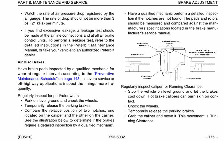
PART 8: MAINTENANCE AND SERVICE BRAKE ADJUSTMENT
(R05/10) Y53-6032 – 175 –
• Watch the rate of air pressure drop registered by theair gauge. The rate of drop should not be more than 3psi (21 kPa) per minute.
• If you find excessive leakage, a leakage test shouldbe made at the air line connections and at all air brakecontrol units. To perform a leakage test, refer to thedetailed instructions in the Peterbilt MaintenanceManual, or take your vehicle to an authorized Peterbiltdealer.
Air Disc Brakes
Have brake pads inspected by a qualified mechanic forwear at regular intervals according to the “PreventiveMaintenance Schedule” on page 143. In severe service oroff-highway applications inspect the linings more fre-quently.
Regularly inspect for pad/rotor wear:• Park on level ground and chock the wheels.• Temporarily release the parking brakes.• Compare the relative position of two notches; one
located on the caliper and the other on the carrier.See the illustration below to determine if the brakesrequire a detailed inspection by a qualified mechanic.
• Have a qualified mechanic perform a detailed inspec-tion if the notches are not found. The pads and rotorsshould be measured and compared against the man-ufacturers specifications located in the brake manu-facturer’s service manual.
Regularly inspect caliper for Running Clearance:• Stop the vehicle on level ground and let the brakes
cool down. Hot brake calipers can burn skin on con-tact.
• Chock the wheels.• Temporarily release the parking brakes.• Grab the caliper and move it. This movement is Run-
ning Clearance.
Y53-6032.book Page 175 Monday, May 24, 2010 3:37 PM

BRAKE ADJUSTMENT PART 8: MAINTENANCE AND SERVICE
– 176 – Y53-6032 (R05/10)
• Proper Running Clearance is 0.08” (2 mm) of move-ment of the brake caliper (approximately the thicknessof a nickel) in the inboard/outboard direction.
• Have a qualified mechanic provide further inspectionif the caliper does not move or appears to move morethan the specified clearance.
Drum Brakes
Have brake drum linings and disc brake pads inspected bya qualified mechanic for wear at regular intervals accord-ing to the maintenance schedule. In severe service or off-highway applications inspect the linings more frequently.
Automatic Slack Adjusters
Periodically check the Brake Chamber Stroke. Replacethe slack adjuster if proper stroke cannot be maintained.
Operational checks of automatic slack adjusters
• Measure brake chamber stroke with the spring brakereleased and the air pressure no less than 100 psi(690 kPa).
• Brake Chamber Stroke is the difference between theapplied and the retracted position of the air chamberpushrod.
• A correctly installed and functioning auto slackadjuster will produce the following strokes:
Chamber Type Stroke
36 (rear brakes) 11/2” - 21/4” (38 - 57 mm)
30 (rear brakes) 11/2” - 2” (38 - 51 mm)
16, 20, & 24 (front brakes) 1” - 13/4” (25.4 - 44.4 mm)
02945a
Brake Chamber Stroke
Y53-6032.book Page 176 Monday, May 24, 2010 3:37 PM
PART 8: MAINTENANCE AND SERVICE TIRES, WHEELS, AND RIMS
(R05/10) Y53-6032 – 177 –
WARNING! Manual adjustment of automatic slack adjusters is a dangerous practice that could result in an accident involving death or injury. It gives the operator a false sense of security about the effectiveness of the brakes. Contact the Service Department at your dealer-ship if the stroke exceeds the above specifica-tions. A stroke exceeding these values may indicate a problem with the slack adjuster or the brake foundation.
Tires, Wheels, And RimsTires
WARNING! Use only original equipment manu-factured (OEM) components. Use of non-originalequipment could cause wheel breakage andwheel separation from vehicle, which couldresult in an accident causing death or personalinjury. Each mounting system is engineeredonly for use with its correct mating part. Be surethat properly matched components are used foreach type of mounting. The comparison chart onPage 184 illustrates the differences between
parts used in hub-piloted mount and ball seat mountapplications. Only OEM supplied hub-piloted or ball-seatmounted wheels may be used on this vehicle.
• If you are not fully qualified and not equippedwith the proper tools and equipment, do notattempt to raise the vehicle or remove or installthe damaged tire and wheel assembly. Obtainexpert help. A person can be killed or seriouslyinjured and/or damage can result from using thewrong service methods. Truck tires and wheelsshould be serviced only by trained personnelusing proper equipment. Do not reinflate a tirethat has been run flat or is seriously low on airwithout first removing the tire from the rim andinspecting for damage.
• Follow OSHA regulations per section 1910.177.
• Follow all warnings and cautions containedwithin the tire and wheel manufacturers litera-ture.
• Only properly trained personnel should servicetire and rim assemblies.
Your tires are a very important part of your vehicle’s wholebraking system. How fast you can stop depends on howmuch friction you get between the road and your tires. In
Y53-6032.book Page 177 Monday, May 24, 2010 3:37 PM
TIRES, WHEELS, AND RIMS PART 8: MAINTENANCE AND SERVICE
– 178 – Y53-6032 (R05/10)
addition, keeping your tires in good condition is essentialto the safe, efficient operation of your vehicle. Regular, fre-quent inspection and the right care will give you the assur-ance of safe and reliable tire operation. Here are sometips on maintaining your tires.
Checking Inflation Pressure
Give your tires a visual test every day, and check inflationwith a gauge every week:
• When checking tire pressure, inspect each tire fordamage to sidewalls, cuts, cracks, uneven wear, rocksbetween duals, etc. If a tire appears underinflated,check for damage to the wheel assembly. Don’t forgetto check between dual wheels. If you find wheel dam-age, have an expert tire service repair it.
• Maximum tire pressure will be indicated on the side-wall of a tire.
• Check pressure only when the tires are cool. Warm orhot tires cause pressure buildup and will give you aninaccurate reading. So never deflate a warm tire tothe specified pressure.
• Lower tire pressure does not give you more tractionon ice or snow. This is an old myth that refuses to die.Underinflation actually reduces traction, steering con-trol and tire load capacity.
Underinflated Tires
Low pressure is a tire’s worst enemy. Underinflation allowstires to flex improperly, causing high temperatures to buildup. Heat causes early tire damage such as flex break,radial cracks, and ply separation. Low pressure may affectcontrol of your vehicle, especially at the front wheels. Mosttire wear problems are caused by underinflation as theresult of slow leaks, so you’ll want to check tire pressureregularly.
WARNING! Do not operate vehicle with underin-flated tires. The extra heat caused by underinfla-tion can cause sudden tire failure such as a tirefire or blow out which can cause an accidentresulting in death or personal injury. Low pres-sure may affect control at the front wheels,which could result in an accident and seriousinjury. Keep your tires inflated to the manufac-turer's recommended air pressure.
Y53-6032.book Page 178 Monday, May 24, 2010 3:37 PM

PART 8: MAINTENANCE AND SERVICE TIRES, WHEELS, AND RIMS
(R05/10) Y53-6032 – 179 –
Overloaded tires
Overloading your truck is as damaging to your tires asunderinflation. The following chart shows how neglect ordeliberate abuse can affect the life of your tires.
WARNING! Do not exceed the load rating ofyour tires (molded on the side wall of your tire)or the maximum vehicle load rating, whicheveris less. Overloading could result in prematuretire failure causing you to loose control of yourvehicle and result in an accident causing deathor personal injury. The maximum vehicle loadrating (GVWR) is found on the Tire and Rim Datalabel on the driver's door.
Overinflated tires
Too much air pressure reduces the tire tread contact areaand results in rapid wear in the center of the tread.
WARNING! Overinflated tires can cause acci-dents. They wear more quickly than properlyinflated tires and are more subject to punctures,cracks, and other damage. They could fail andcause you to lose control of your vehicle result-ing in an accident causing death or personalinjury. Be sure all tires are inflated correctlyaccording to the manufacturer's recommenda-tions.
The chart on page 182 gives you the right load and infla-tion rates for different tire sizes. Please follow it for the saf-est and most economical use of your tires. (Consult thetire manufacturer for proper pressure settings with tiresnot listed in this table.)
Matching tires
Be sure to buy matched tires for your vehicle, especiallyon the rear axles. Mismatched tires can cause stressbetween axles and cause the temperature of your axlelubricant to get too hot. Matched tires will help your drive-line last longer and will give you better tire mileage.
Table 11 Effect of Load Pressure on Tire Life
Vehicle Load
Normal 20% Over
40% Over
60% Over
80% Over
100% Over
Tire Pres-sure
Normal 20% Low
30% Low
35% Low
45% Low
55% Low
Expected Total Tire Mileage
Normal 70% 50% 40% 30% 25%
Y53-6032.book Page 179 Monday, May 24, 2010 3:37 PM

TIRES, WHEELS, AND RIMS PART 8: MAINTENANCE AND SERVICE
– 180 – Y53-6032 (R05/10)
WARNING! Do not mismatch wheel compo-nents. Equipment that does not exactly matchoriginal specifications or that is mismatchedcould cause the wheels to break and separatefrom the vehicle causing death or personalinjury. Each mounting system is engineered foruse only with its correct mating part. Be sureproperly matched components are used for eachtype of mounting.
Replacing Tires
WARNING! Do not install regrooved or rein-forcement-repaired tires on steering axles.They could fail unexpectedly and cause you tolose control of your vehicle resulting in anaccident causing death or personal injury.
Front: Replace front tires when less than 4/32 in. of treadremains. Check at three places equally spaced around thetire.
Drive Axles or Trailers: Replace tires on drive axles ortrailers when less than 2/32 in. of tread depth remains inany major groove. Check at three places equally spacedaround the tire. See the next illustration for recommendedmeasuring points for tread depth.
WARNING! .Do not replace original equipmenttires with load ratings less than the originaltires. Doing so could lead to unintentional over-loading of the tire, which could cause a failureresulting in loss of vehicle control and an acci-dent causing death or personal injury.
Y53-6032.book Page 180 Monday, May 24, 2010 3:37 PM
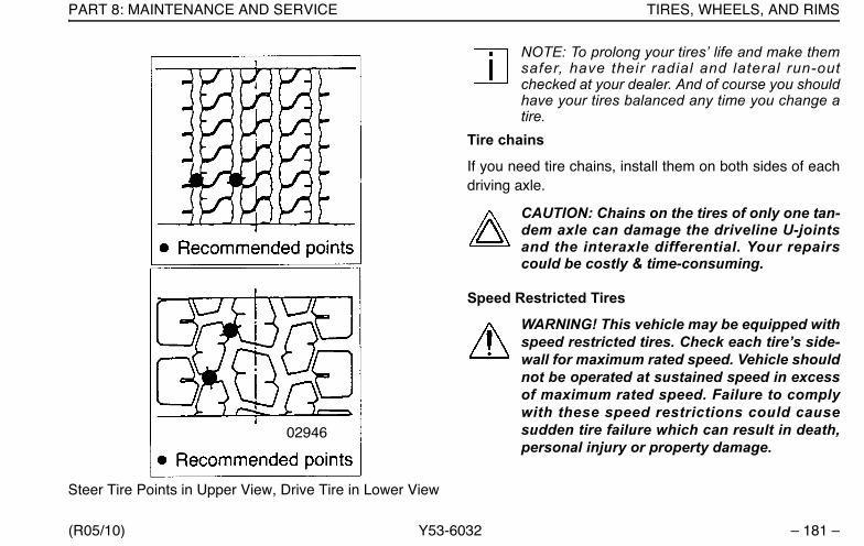
PART 8: MAINTENANCE AND SERVICE TIRES, WHEELS, AND RIMS
(R05/10) Y53-6032 – 181 –
NOTE: To prolong your tires’ life and make themsafer, have their radial and lateral run-outchecked at your dealer. And of course you shouldhave your tires balanced any time you change atire.
Tire chains
If you need tire chains, install them on both sides of eachdriving axle.
CAUTION: Chains on the tires of only one tan-dem axle can damage the driveline U-jointsand the interaxle differential. Your repairscould be costly & time-consuming.
Speed Restricted Tires
WARNING! This vehicle may be equipped withspeed restricted tires. Check each tire’s side-wall for maximum rated speed. Vehicle shouldnot be operated at sustained speed in excessof maximum rated speed. Failure to complywith these speed restrictions could causesudden tire failure which can result in death,personal injury or property damage.
Steer Tire Points in Upper View, Drive Tire in Lower View
02946
Y53-6032.book Page 181 Monday, May 24, 2010 3:37 PM

TIRE LOAD AND INFLATION TABLES PART 8: MAINTENANCE AND SERVICE
– 182 – Y53-6032 (R05/10)
Tire Load and Inflation TablesTable 12 Load Range Letters and Corresponding Ply Rating
( G = 14 ply; H = 16 ply)SINGLE RADIAL TIRES FOR VEHICLES IN HIGHWAY SERVICE
TireSize
LoadRange
Tire Load Limits At Various Cold Inflation Pressures (psi)70 75 80 85 90 95 100 105 110 115 120
11R22.5 G 4530 4770 4990 5220 5510 5730 5950 617511R22.5 H 4530 4770 4990 5220 5510 5730 5950 6175 6320 6465 661011R24.5 G 4820 5070 5310 5550 5840 6095 6350 661011R24.5 H 4820 5070 5310 5550 5840 6095 6350 6610 6790 6970 7160
275 / 70R22.5 H 4850 5050 5250 5480 5705 5945 6195 6450 6720 7000295 / 75R22.5 G 4500 4725 4940 5155 5370 5510 5780 5980 6175285 / 75R24.5 G 4545 4770 4940 5210 5420 5675 5835 6040 6175
DUAL RADIAL TIRES FOR VEHICLES IN HIGHWAY SERVICE11R22.5 G 4380 4580 4760 4950 5205 5415 5625 584011R22.5 H 4380 4580 4760 4950 5205 5415 5625 5840 5895 5950 600511R24.5 G 4660 4870 5070 5260 5510 5675 5840 600511R24.5 H 4660 4870 5070 5260 5510 5675 5840 6005 6205 6405 6610
275 / 70R22.5 H 4430 4610 4795 5005 5210 5430 5660 5890 6135 6395295 / 75R22.5 G 4095 4300 4540 4690 4885 5070 5260 5440 5675285 / 75R24.5 G 4135 4340 4540 4740 4930 5205 5310 5495 5675
NOTES:• Pressure listed is the minimum for the load.• All tire load figures are in pounds.• Figures in Bold face indicate maximum recommended load.
Source: Bridgestone Tire 2/02
Y53-6032.book Page 182 Monday, May 24, 2010 3:37 PM
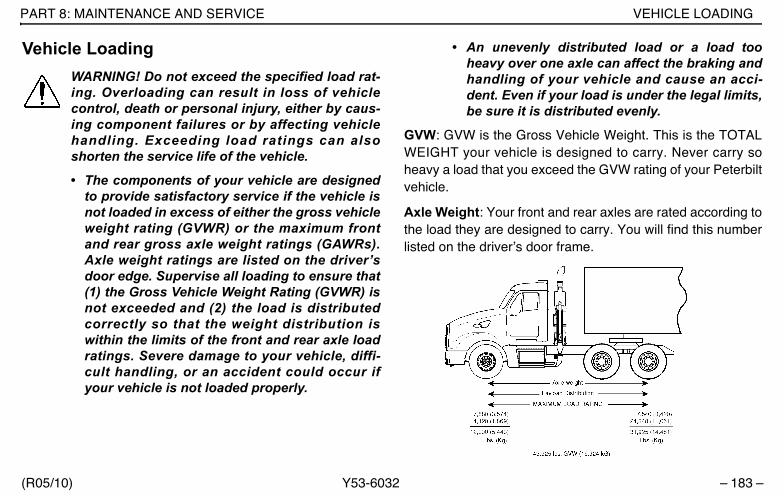
PART 8: MAINTENANCE AND SERVICE VEHICLE LOADING
(R05/10) Y53-6032 – 183 –
Vehicle LoadingWARNING! Do not exceed the specified load rat-ing. Overloading can result in loss of vehiclecontrol, death or personal injury, either by caus-ing component failures or by affecting vehiclehandling. Exceeding load ratings can alsoshorten the service life of the vehicle.
• The components of your vehicle are designedto provide satisfactory service if the vehicle isnot loaded in excess of either the gross vehicleweight rating (GVWR) or the maximum frontand rear gross axle weight ratings (GAWRs).Axle weight ratings are listed on the driver’sdoor edge. Supervise all loading to ensure that(1) the Gross Vehicle Weight Rating (GVWR) isnot exceeded and (2) the load is distributedcorrectly so that the weight distribution iswithin the limits of the front and rear axle loadratings. Severe damage to your vehicle, diffi-cult handling, or an accident could occur ifyour vehicle is not loaded properly.
• An unevenly distributed load or a load tooheavy over one axle can affect the braking andhandling of your vehicle and cause an acci-dent. Even if your load is under the legal limits,be sure it is distributed evenly.
GVW: GVW is the Gross Vehicle Weight. This is the TOTALWEIGHT your vehicle is designed to carry. Never carry soheavy a load that you exceed the GVW rating of your Peterbiltvehicle.
Axle Weight: Your front and rear axles are rated according tothe load they are designed to carry. You will find this numberlisted on the driver’s door frame.
Y53-6032.book Page 183 Monday, May 24, 2010 3:37 PM

VEHICLE LOADING PART 8: MAINTENANCE AND SERVICE
– 184 – Y53-6032 (R05/10)
Load Distribution: Be sure any load you carry is distributedso that no axle has to support more than its load limit.
Wheels And Rims
Hub Pilot Mount System Ball Seat Mount System
Hub, Drum, and Stud Assembly
• The hub pilot mounting system uses M22x1.5 metricthreads (about 7/8 in. dia.). The stud stands out at least1.9 in. beyond the brake drum. All studs are right handthreads. Pilot bosses machined on the hub fit tightly tothe wheel center bore.
• The ball seat mounting system uses 3/4 x 16 or1-1/8 x 16 threads. The dual mounting studs provide 1.3 -1.44 in. standout. Right hand and left hand threads arerequired. Inner and outer cap nuts center the wheels byseating against wheel ball seats.
Wheels
• Pilot mount wheels have stud holes that are reamedstraight through (no ball seats). Center bore diameter is8-21/32 in. Budd Uni-Mount - 10 wheels have UNI-MOUNT stamped on the disc.
• Ball seat wheels have spherical chamfers machined oneach stud hole. Center bore diameter is 8-23/32 in.
02949
Y53-6032.book Page 184 Monday, May 24, 2010 3:37 PM

PART 8: MAINTENANCE AND SERVICE VEHICLE LOADING
(R05/10) Y53-6032 – 185 –
Wheel Nuts
• Hub pilot nut has a hex body and a flange for clamp-ing against wheel face. Hex size is 33 mm (same as 1-5/16 in.).
• Inner and outer cap nuts mate with spherical cham-fers on wheels. Inner nut has 13/16 in. square end.Outer nut has 1-1/2 in. hex.
WARNING! Do not mismatch wheel compo-nents. Equipment that does not exactly matchoriginal specifications or that is mismatchedcould cause the wheels to break and separatefrom the vehicle causing death or personalinjury. Each mounting system is engineered foruse only with its correct mating part. Be sureproperly matched components are used for eachtype of mounting.
Wheel Cap Nut Torque
At the first 100 miles, have all wheel cap nuts torqued totheir specified value. After that, check wheel cap nuts atleast once a week. Contact the Service Department atyour dealership for information on the proper installation
procedure for the wheels on your truck. This is a job youmay not be able to do yourself. You need the right torquingequipment to do it.
WARNING! • Never use oil or grease on studs or nuts;
improper torque readings will result, whichcould cause improper wheel clamping andcould lead to a wheel failure resulting in anaccident causing death or personal injury.
• Tighten wheel cap nuts properly. If they arenot tightened properly, wheel nuts could even-tually cause the wheel to become loose, tofail, and/or to come off while the vehicle ismoving, possibly causing loss of control if thevehicle and death, serious personal injury ordamage to the vehicle.
Wheel Bearing Adjustment
For safe, reliable operation and adequate service life, yourwheel bearings must be checked and adjusted properly.The person best equipped to do this is your authorizeddealer’s service mechanic.
Y53-6032.book Page 185 Monday, May 24, 2010 3:37 PM

VEHICLE LOADING PART 8: MAINTENANCE AND SERVICE
– 186 – Y53-6032 (R05/10)
Disc Wheels
To check the torque on disc wheels, follow the crisscrosssequence shown. See the Specifications chart for propertorque specification.
WARNING! Use the correct components andtools when working on wheels. Grooves in thewheel disc or other damage to the disc canweaken the wheel and cause it to eventuallycome off. This could cause you to lose control ofyour vehicle, and may result in an accident caus-ing death or personal injury.
Crisscross Sequence For Disc Wheels
Demountable Rims
To check the torque on demountable rims, follow the criss-cross sequence shown. See the Specifications chart forproper torque specification.
WARNING! Improperly mounting and demount-ing tire and rim assemblies is dangerous. Failureto observe proper precautions could cause thetire-rim assembly to burst explosively, causingserious injury or death. See the wheel manufac-turer's literature for the proper way to mount anddemount your tires and rims. Follow their pre-cautions exactly.
02950
Y53-6032.book Page 186 Monday, May 24, 2010 3:37 PM

PART 8: MAINTENANCE AND SERVICE VEHICLE LOADING
(R05/10) Y53-6032 – 187 –
Crisscross Sequence For Demountable Rims
02951
Table 13 Cap Nut Torque Specifications (R12/01)
WHEEL AND NUT CONFIGURATION STUD SIZE
TORQUES FOR INNER & OUTER CAP NUTS
Lb. Ft. N.m
Stud-Piloted Disc Wheels
3/4”-16 Inner 1 1/8”-16 Outer
450-500 610-680
Heavy Duty Stud-Piloted Disc Wheels
15/16”-12 Inner 1 5/16”-12
Outer750-900 1025-1225
PHP-10; Budd Uni-Mount-10; WHD-8
M22 x 1.5-6H 450-500 610-680
Cast Spoke Wheel Assembly
1/2” Dia.5/8” Dia.3/4” Dia.
Rim Clamp Nut Torque
80-90 110-120
160-185 220-250
225-245 305-335
Y53-6032.book Page 187 Monday, May 24, 2010 3:37 PM
YOUR VEHICLE’S AIR SYSTEM PART 8: MAINTENANCE AND SERVICE
– 188 – Y53-6032 (R05/10)
Your Vehicle’s Air SystemWARNING! Prior to the removal of any air sys-tem component, always block and hold thevehicle by a secure means other than thevehicle's own brakes. Depleting air systempressure may cause vehicle to roll which mayresult in an accident involving death or per-sonal injury. Keep hands away from chamberpush rods and slack adjusters, they mayapply as system pressure drops.
• After completing any repairs to the air sys-tem, always test for air leaks, and check thebrakes for safe operation before putting thevehicle in service.
• Never connect or disconnect a hose or linecontaining air pressure. It may whip as airescapes. Never remove a component orpipe plug unless you are certain all systempressure has been depleted.
• Never exceed recommended air pressureand always wear safety glasses when work-ing with air pressure. Never look into air jetsor direct them at anyone.
• Never attempt to disassemble a componentuntil you have read and understood recom-mended procedures. Some componentscontain powerful springs and injury canresult if not properly disassembled. Useonly proper tools and observe all precau-tions pertaining to use of those tools.
• Completely bypassing a Bendix AD-IS airdryer will bypass the system’s pressureprotection valves. This could lead to loss ofair pressure or damage to the vehicle’s airsystem, which could cause an accident orpersonal injury. Always adhere to the manu-facturer’s procedure if it is necessary in anemergency to temporarily bypass an AD-IS-series air dryer.
The operation of the vehicle’s braking system and manyvehicle accessories depends upon the storage and appli-cation of a high-pressure air supply.
Your vehicle’s compressor takes outside air and com-presses it, usually to 100-120 psi. The compressed airthen goes to the reservoirs to be stored until needed.When you operate your air brakes, the stored compressedair flows into the chambers where it is used to apply your
Y53-6032.book Page 188 Monday, May 24, 2010 3:37 PM
PART 8: MAINTENANCE AND SERVICE YOUR VEHICLE’S AIR SYSTEM
(R05/10) Y53-6032 – 189 –
truck and trailer brakes. That is why, when you push downon your brake pedal, you don’t feel the same amount ofpressure on the pedal that you do when you apply thebrakes on your car. All you are doing on your truck isopening an air valve to allow air to flow into the brakechambers.
Air Supply SystemWARNING! Do not operate the vehicle if leak-age in the air system is detected. Conduct thefollowing procedure and contact an autho-rized Peterbilt Dealer (or any other properlyequipped service center) if a leak is detected.Failure to check the brakes or follow theseprocedures could cause a system failure,increasing the risk of an accident involvingdeath or personal injury.
Contamination of the air supply system is the major causeof problems in air-operated components such as brakevalves, wiper motors, and suspension height controlvalves. To keep contaminants to the lowest possible level,follow these maintenance procedures.
WARNING! If the supply and service tanks arenot drained at the recommended frequency,water could be sent to all air lines and valves.This could cause corrosion, which could com-promise the brake system safety and potentiallycause an accident involving death or personalinjury.
Daily• Drain moisture from the supply and service air tanks.• Operate air devices to circulate lubricants within the
unit.
Periodically
• Clean filter screens ahead of the valves by removingthe screens and soaking them in solvent. Blow themdry with pressurized air before reinstalling them.
Twice a Year
• Add approximately 1/4 oz. (7.5 ml) of light viscositylubricant to the air line leading to the wiper motor.Acceptable lubricants are Dow Corning 200 fluid, 200CS viscosity, and Sprague Wiper Lube. If you havealcohol dryers installed in the air system, the alcoholcan wash away lubricants from the wiper motors.
Y53-6032.book Page 189 Monday, May 24, 2010 3:37 PM
YOUR VEHICLE’S AIR SYSTEM PART 8: MAINTENANCE AND SERVICE
– 190 – Y53-6032 (R05/10)
CAUTION: Don’t use penetrating oil, brake fluid,or wax-based oils in the air system. These fluidsmay cause severe damage to air system compo-nents.
• Maintain the air compressor to prevent excessive oilby-pass. See your shop manual for maintenancedetails.
• Replace worn seals in valves and air motors as theyare needed.
Air DryerWARNING! Use of incorrect air dryer couldcause air system failure, leading to loss of vehi-cle control and serious personal injury or death.If your vehicle is equipped with a Bendix AD-ISair dryer, it is important that future replacementsbe identical or similar in design.
Any deviation from the Bendix AD-IS type airdryer would require changes to the vehicle air system.Some vehicles use a dual air system consisting of a wettank, forward dry tank, and rear dry tank. The dry tankshave a single-check valve in the tank inlet. The checkvalves prevent a complete loss of air in the event of an airsystem failure (tank or hose failure). This ensures a con-
trolled stop (with reduced braking capability). Other vehi-cles use a Bendix AD-IS air dryer which eliminates theneed for a wet tank and check valves in the dry tanks.
NOTE: A small amount of oil in the system may benormal and should not, by itself, be considered rea-son to replace a desiccant cartridge; oil-staineddesiccant can function adequately.
Every 900 operating hours or 30,000 miles/48,000 km or 3months, check for moisture in the air brake system byopening reservoirs, drain valves, or valves and checkingfor the presence of water. A tablespoon of water in a res-ervoir would point to the need for a desiccant cartridgechange. However, the following should be considered first:
• Air usage is exceptionally high/abnormal for a high-way vehicle. This may be due to accessory airdemands or some other unusual air requirement thatdoesn’t allow the compressor to load/unload in a nor-mal fashion or it may be due to excessive leaks in theair system.
• When more than a 30-degree F (17-degree C) rangeof temperature occurs in one day, small amounts ofwater can accumulate in the air brake system due tocondensation. Under these conditions, the presence
Y53-6032.book Page 190 Monday, May 24, 2010 3:37 PM

PART 8: MAINTENANCE AND SERVICE ENGINE COOLING SYSTEM
(R05/10) Y53-6032 – 191 –
of small amounts of moisture is normal and should notbe considered as an indication that the dryer is notperforming properly.
• An outside air source may have been used to chargethe air system, in which case this air did not passthrough the drying bed.
Engine Cooling SystemYour engine’s cooling system is standard with ExtendedLife Coolant (ELC). ELC consists of a mixture of ethyleneglycol, water, and organic acid technology chemical inhib-itors. ELC prevents corrosion and scale formation as wellas provides freezing and boiling point protection.
CAUTION: The engine cooling system hasvery specific maintenance and inspectionrequirements. Failure to follow requirementscan damage the engine. Engine damage caninclude but is not limited to:•Freezing•Boiling•Corrosion•Pitted cylinder liners
This information is found in the engine manufac-turers owner’s manual. It is the owner’s respon-sibility to follow all requirements listed in theengine manufacturers owner’s manual.
What To Check In An ELC-filled Cooling System
ELC Concentration
Check the level of freeze/boilover protection, which isdetermined by the ELC concentration. Use a glycol refrac-tometer to determine glycol level. Add ELC to obtain theELC to water ratio required to provide the protection youneed. Use the chart below to help determine how muchELC you need to add. In an ELC-filled cooling system, thefreeze point should be maintained between -30° F and -45° F (-34° C and -43° C)
NOTE: Maximum recommended ELC concentra-tion is 60% ELC and 40% water by volume (a 60/40 coolant mixture). The minimum recommendedconcentration is 40%.
Y53-6032.book Page 191 Monday, May 24, 2010 3:37 PM

ENGINE COOLING SYSTEM PART 8: MAINTENANCE AND SERVICE
– 192 – Y53-6032 (R05/10)
ELC Condition (Contamination and Inhibitor Concen-tration)
Perform a visual inspection of the ELC. It should have nocloudiness or floating debris. Determine the chemicalinhibitor concentration level by using an ELC-specific testkit or test strips. Inhibitor concentration level determinescorrosion protection. If you are concerned about possiblecoolant quality, contamination, or mechanical problems,submit a coolant sample for analysis. Improper mainte-nance may cause coolant degradation and could result indamage to the cooling system and engine components.
Consult your dealer or the ELC manufacturer’s represen-tative for recommended ELC test kits, test strips, and lab-oratory sample procedures.
ELC Extender
Add ELC extender if necessary at the maintenance inter-val under “Cooling” on page 152.
Coolant Filter
If your vehicle came with a non-chemical filter (“blank fil-ter”), replace it only with a blank filter at the interval speci-fied in the “Preventive Maintenance Schedule” onpage 143. Never use filters that contain SCAs in an ELC-filled system.
Desired ELC/Water ratio:
0% 10% 15% 20% 25% 30% 35% 40% 45% 50% 55% 60% 65% 70% 75% 80% 85% 90% 100%
Freeze point°F (°C)
+32 (0)
+25(-4)
+20(-7)
+15(-9)
+10(-12)
+5(-15)
-5(-21)
-12(-24)
-23(-31)
-34(-37)
-50(-46)
-65(-54)
-75(-59)
-84(-64)
-70(-57)
-55(-48)
-43(-42)
-30(-34)
-5(-21)
Y53-6032.book Page 192 Monday, May 24, 2010 3:37 PM
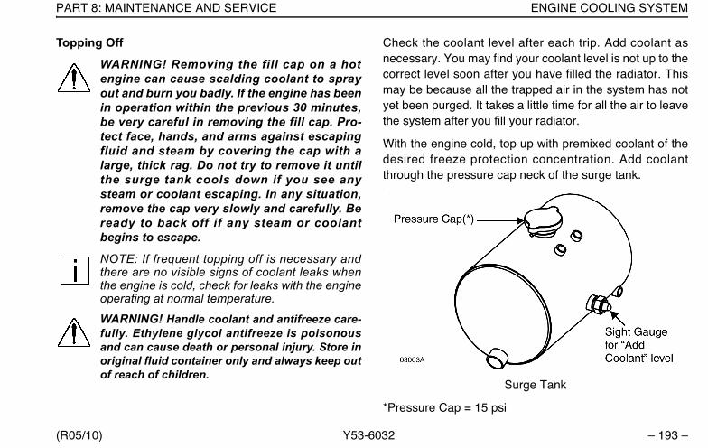
PART 8: MAINTENANCE AND SERVICE ENGINE COOLING SYSTEM
(R05/10) Y53-6032 – 193 –
Topping Off
WARNING! Removing the fill cap on a hotengine can cause scalding coolant to sprayout and burn you badly. If the engine has beenin operation within the previous 30 minutes,be very careful in removing the fill cap. Pro-tect face, hands, and arms against escapingfluid and steam by covering the cap with alarge, thick rag. Do not try to remove it untilthe surge tank cools down if you see anysteam or coolant escaping. In any situation,remove the cap very slowly and carefully. Beready to back off if any steam or coolantbegins to escape.
NOTE: If frequent topping off is necessary andthere are no visible signs of coolant leaks whenthe engine is cold, check for leaks with the engineoperating at normal temperature.
WARNING! Handle coolant and antifreeze care-fully. Ethylene glycol antifreeze is poisonousand can cause death or personal injury. Store inoriginal fluid container only and always keep outof reach of children.
Check the coolant level after each trip. Add coolant asnecessary. You may find your coolant level is not up to thecorrect level soon after you have filled the radiator. Thismay be because all the trapped air in the system has notyet been purged. It takes a little time for all the air to leavethe system after you fill your radiator.
With the engine cold, top up with premixed coolant of thedesired freeze protection concentration. Add coolantthrough the pressure cap neck of the surge tank..
Surge Tank
*Pressure Cap = 15 psi
Y53-6032.book Page 193 Monday, May 24, 2010 3:37 PM

ENGINE COOLING SYSTEM PART 8: MAINTENANCE AND SERVICE
– 194 – Y53-6032 (R05/10)
Proper Coolant Level
NOTE: Do not overfill a cooling system. Excesscoolant may result in overflow, loss of antifreeze,and reduced corrosion protection.
• The proper coolant level for a cold engine is at thebase of the filler neck extension tube.
• The proper coolant level for an engine at normal oper-ating temperature is even with the pressure cap seal.
Refilling Your Radiator
1. If your cooling system is built with petcocks in theupper engine coolant pipe, open them before fillingthe surge tank.
2. Be sure the radiator and engine block drains areclosed.
3. Remove the surge tank pressure cap
4. Through the surge tank, fill the system with premixedcoolant. Pour it in a steady flow until the surge tank isfull. It may be necessary to pause for 1 minute andthen re-fill if the fluid level dropped.
WARNING! Do not ingest ethylene glycolbased antifreeze, it is poisonous. It can beharmful or fatal, especially to children. Storein its original container only and keep it out ofreach of children.
5. If the system has petcocks, close them.
6. Start the engine and idle at a low RPM.
7. During low rpm idle, air will purge from the coolingsystem which will lower the coolant level in the surgetank. Continue to fill the surge tank until the levelremains at the base of the fill neck. This may take upto 2 minutes.
8. Operate the engine throttle unitl the operating temper-ature stabilizes (when the thermostat opens).
9. Fill the surge tank as necessary to raise the coolantlevel to the proper reading.
10. Operate the engine at high idle for another 10 minutesand add coolant to raise the level back up to the baseof the fill neck.
11. Replace the surge tank pressure cap.
Y53-6032.book Page 194 Monday, May 24, 2010 3:37 PM
PART 8: MAINTENANCE AND SERVICE ELECTRICAL
(R05/10) Y53-6032 – 195 –
Check the coolant level after each trip when the enginehas cooled. Add coolant as necessary. You may find yourcoolant level is not up to the correct level soon after youhave filled the radiator. This may be because all thetrapped air in the system has not yet been purged. It takesa little time for all the air to leave the system after you fillyour radiator.
ElectricalCAUTION: Do not modify or improperly repairthe vehicle’s electrical system or power distri-bution box. All electrical repairs should beperformed by a qualified service technician.Improper repair or modifications will voidyour warranty and/or cause serious damageto your vehicle.
Battery CareRegular attention to the charging system will help prolongthe service life of your batteries. Here are some commoncauses of battery failure:
• Overcharge: This condition may result from impropervoltage regulator adjustment. It results in overheatingof the battery, warped plates, and evaporation of elec-trolyte.
• Undercharge: Your voltage regulator may be mal-functioning or is improperly adjusted, the drive belt isslipping, or your vehicle has undergone long periodsof standing idle or short distance driving. These con-ditions result in battery plates becoming covered witha hard coating.
• Vibration: Loose battery hold-downs may cause bat-tery plate failure.
• Short Circuits: These discharge a battery by drain-ing electricity.
• Dirty or Loose Connections: Bad connections maystop the flow of electrical power to and from the bat-tery.
Y53-6032.book Page 195 Monday, May 24, 2010 3:37 PM
ELECTRICAL PART 8: MAINTENANCE AND SERVICE
– 196 – Y53-6032 (R05/10)
Recharging Batteries
Except for using small trickle chargers to maintain batterycondition, you should have your vehicle’s batteriescharged by a qualified service facility. To help reduce therisk of personal injuries, follow these guidelines carefullywhen recharging a battery:
WARNING! Batteries can kill or injure youseverely. They contain acid, produce poisonousand explosive gases, and supply levels of elec-tric current high enough to cause burns. A sparkor flame near a battery on charge may cause it toexplode with great force.
• Allow no sparks or open flame anywhere near thecharging area.
• Charge a battery only in a well-ventilated area, suchas outdoors or in a fully open garage which containsno pilot lights or other flames.
• Always make sure the battery charger is OFF beforeconnecting or disconnecting the cable clamps.
WARNING! Always shield your eyes, your skinand painted surfaces to from contact with batt-tery fluid. Batteries contain a corrosive fluidwhich can cause death or severe personalinjury.
• Use protective eyewear.
CAUTION: Never use a metallic funnel to adddistilled water. It could come in contact with aterminal, creating a short circuit, resulting insevere injury or damage to your vehicle.
• Maintain the full level of electrolyte in the batteries.This reduces the volume of gas in the cells. The elec-trolyte level should always be between 0.4–0.6 in.(10–15mm) above plates. Fill with distilled wateronly. After distilled water has been added, wait atleast a half hour to measure solution density (specificgravity). The specific gravity should be between1.258–1.265 or the electrolyte level within “MIN” and“MAX” marks.
Y53-6032.book Page 196 Monday, May 24, 2010 3:37 PM

PART 8: MAINTENANCE AND SERVICE ELECTRICAL
(R05/10) Y53-6032 – 197 –
• Before attempting any work on the batteries or electri-cal system, remove all jewelry. If metal jewelry orother metal comes in contact with electrical circuits, ashort circuit may occur causing you to be injured—plus electrical system failure and damage.
• To avoid short circuits and damage to yourself or thevehicle, never place metal tools or jumper cables onthe battery or nearby. Metal that accidentally comes incontact with the positive battery terminal or any othermetal on the vehicle (that is in contact with the posi-tive terminal), could cause a short circuit or an explo-sion.
• Keep all batteries away from children.
WARNING! Charger cables must be connectedpositive to positive (+ to +) and negative to neg-ative (– to –). If connected improperly, batteriescould explode causing death or serious per-sonal injury.
• Always make sure the battery charger isOFF before connecting or disconnectingthe cable clamps. To reduce the danger ofexplosions and resulting death or serious
personal injury, do not connect or discon-nect charger cables while the charger isoperating.
• Never reverse battery polarity.
• Battery terminals should not be coated with impropergrease. Use petroleum jelly or commercially available,noncorrosive, nonconducting terminal coatings.
• Keep the battery clean and dry.
• Look for any signs of damage.
WARNING! Examine the battery and alternatorcables for signs of damage or chaffing. Achaffed or damaged cable, in which wiring isexposed, can arch against metal componentsand cause a fire which can lead to death, per-sonal injury or damage to equipment.
• Battery acid that may spill during charging should bewashed off with a solution of warm water and bakingsoda to neutralize the acid. If you accidentally get acidin your eyes or on your skin, immediately rinse withcold water for several minutes and call a doctor.
Y53-6032.book Page 197 Monday, May 24, 2010 3:37 PM

ELECTRICAL PART 8: MAINTENANCE AND SERVICE
– 198 – Y53-6032 (R05/10)
• Do not charge a frozen battery; allow it to thaw outfirst. And always allow the battery to thaw gradually—do not apply direct heat. Gas trapped in the ice maycause an explosion.
• Never attempt to place the vehicle in motion, or runthe engine with batteries disconnected.
• When fast charging, remove the battery caps so pres-sure doesn’t accumulate.
• Never use a fast charger as a booster to start theengine. This can seriously damage sensitive elec-tronic components such as relays, radio, etc., as wellas the battery charger. Fast charging a battery is dan-gerous and should only be attempted by a competentmechanic with the proper equipment.
Slow Battery Charging
NOTE: Follow the instructions that come withyour battery charger. It is not necessary toremove the battery from the compartment.
1. Make sure the electrolyte level in each cell is betweenthe “MIN” and “MAX” marks. If the fluid level is belowthe “MIN” mark, correct the condition.
2. Disconnect the battery cables.
3. Connect charger cables.
4. Start charging the battery at a rate not over 6amperes. Normally, a battery should be charged at nomore than 10 percent of its rated capacity.
5. After charging, turn OFF charger and disconnectcharger cables.
Jump Starting Batteries
If your battery is discharged (dead), you may be able tostart it by using energy from a good battery in anothervehicle. This is termed “jump starting.” Because of the var-ious battery installations in optional electrical systems,Peterbilt does not recommend that you attempt to jumpstart your vehicle. If you have a battery problem, contact aPeterbilt Dealer or a reputable towing service. But if youare unable to do this, and must jump-start your vehicle,then ensure that you follow the precautions and instruc-tions below.
Y53-6032.book Page 198 Monday, May 24, 2010 3:37 PM
PART 8: MAINTENANCE AND SERVICE ELECTRICAL
(R05/10) Y53-6032 – 199 –
WARNING! Batteries contain acid that canburn and gasses that can explode. Ignoringsafety procedures can possible cause deathor severe personal injury.
• Never jump start a battery near fire, flames,or electrical sparks. Batteries generateexplosive gases. Keep sparks, flame, andlighted cigarettes away from batteries.
• Do not allow battery fluid to contact eyes,skin, fabrics, or painted surfaces. Alwayswear eye protection. Battery acid that mayspill during charging should be washed offwith a solution of warm water and bakingsoda to neutralize the acid. If you acciden-tally get acid in your eyes or on your skin,immediately rinse with cold water for sev-eral minutes and call a doctor.
• Be careful that metal tools or any metal incontact with the positive terminal do notcontact the positive battery terminal andany other metal on the vehicle at the sametime. Remove metal jewelry; avoid leaningover a battery. If metal jewelry or othermetal comes in contact with electrical cir-
cuits, a short circuit may occur causing youto be killed or injured—plus electrical sys-tem failure and damage to the vehicle.
• Do not try to jump start or charge a frozenbattery. (Even a battery with ice particles onthe electrolyte surface is dangerous.) Allowit to thaw out first. And always allow batteryto thaw gradually—do not apply direct heat.Gas trapped in the ice may cause an explo-sion.
• Do not try to jump start a vehicle if the elec-trolyte level in the battery of either vehicle islow. Maintain the full level of electrolyte inthe batteries. This reduces the volume ofgas in the cells.
• The voltage of the booster battery musthave a 12–volt rating. And the capacity ofthe booster battery should not be lowerthan that of the discharged battery. Use ofbatteries of different voltage or substan-tially different capacity rating may cause anexplosion. To avoid serious personal injuryand damage to the vehicle, heed all warn-ings and instructions of the jumper cable
Y53-6032.book Page 199 Monday, May 24, 2010 3:37 PM
ELECTRICAL PART 8: MAINTENANCE AND SERVICE
– 200 – Y53-6032 (R05/10)
manufacturer. The jumper cables must belong enough so that the vehicles do nottouch.
• Applying a higher voltage booster batterywill cause expensive damage to sensitiveelectronic components, such as relays, andthe radio. Improper hook–up of jumpercables or not following these procedurescan cause death, personal injury or damageto equipement.
• Battery posts, terminals, and related acces-sories contain lead and lead compounds,chemicals known to the State of Californiato cause cancer and reproductive harm.Wash hands after handling.
• To avoid serious personal injury and dam-age to the vehicle, heed all warnings andinstructions of the jumper cable manufac-turer.
CAUTION: Departures from these procedurescould also cause serious damage to bothvehicles. Improper use of a booster battery tostart a vehicle may cause an explosion.
To Jump Start Your Vehicle:
1. Wear eye protection and remove rings, metal watchbands, and any other metal jewelry.
2. Set the parking brakes. Place the transmissions ofboth vehicles in Neutral. Do not let the vehicles touchone another. Turn the ignition key to Off in the vehiclewith the discharged battery. Also turn off lights,heater, and any other unnecessary electrical load.
3. If either battery has vent caps, remove them andcheck the fluid level. If it is OK, replace the capsbefore going further. If the level is low, add distilledwater, and replace the caps before proceeding. If nowater is available, remove the caps and cover the filleropenings with a cloth before proceeding. After jumpstarting the vehicle, dispose of the cloth.
WARNING! If you do not cover the filler open-ings on the battery, electrolyte could boil outof the openings and cause death, seriousinjury or equipement damage. Replace capssecurely if there is enough fluid in the battery,or cover with a cloth if no water is availableand your fluid is low.
Y53-6032.book Page 200 Monday, May 24, 2010 3:37 PM
PART 8: MAINTENANCE AND SERVICE ELECTRICAL
(R05/10) Y53-6032 – 201 –
4. Attach one end of a jumper cable to the dead battery’spositive terminal. This will have a large red “+” or “P”on the battery case, post, or clamp. Attach the otherend of the same cable to the positive terminal of thegood battery.
5. Attach the remaining jumper cable FIRST to the neg-ative battery terminal (black “-” or “N”) of the good bat-tery, and then to the chassis or ground of the vehiclebeing jump started.
6. Start the engine in the vehicle with the good battery.Let it run a few minutes. Then start the engine in thevehicle with the dead battery. If the engine fails to start,do not continue to crank the starter but contact the near-est Authorized Service Center.
WARNING! When disconnecting jumper cables,make sure they do not get caught in any movingparts in the engine compartment. Failure tocomply may result in death or personal injury.
7. Reverse the above sequence exactly when removingthe jumper cables. Take care that your first step is toremove the cable from the chassis or ground of thevehicle that was jump-started.
Removing and Installing Batteries
WARNING! Always reinstall the battery com-partment cover (step) before entering the cab.Without the battery cover you could slip andfall, resulting in death or personal injury.
Whenever you have to install a battery or remove one, fol-low these guidelines for the safety of yourself and the bat-tery.
• Ensure all switches on the vehicle are turned Off.
• Disconnect the ground cable first when removing abattery.
• Connect the ground cable last when installing a bat-tery.
Headlamp AdjustmentFollow the procedure below to adjust a headlamp. Verticaladjustment is controlled via an access hole on the back-side of the headlamp assembly and a 10mm socket.Access to this adjuster knob is gained from inside thefender well. The headlights have vertical adjustment only.
Y53-6032.book Page 201 Monday, May 24, 2010 3:37 PM
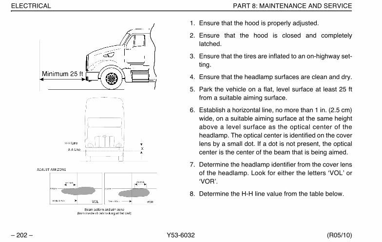
ELECTRICAL PART 8: MAINTENANCE AND SERVICE
– 202 – Y53-6032 (R05/10)
1. Ensure that the hood is properly adjusted.
2. Ensure that the hood is closed and completelylatched.
3. Ensure that the tires are inflated to an on-highway set-ting.
4. Ensure that the headlamp surfaces are clean and dry.
5. Park the vehicle on a flat, level surface at least 25 ftfrom a suitable aiming surface.
6. Establish a horizontal line, no more than 1 in. (2.5 cm)wide, on a suitable aiming surface at the same heightabove a level surface as the optical center of theheadlamp. The optical center is identified on the coverlens by a small dot. If a dot is not present, the opticalcenter is the center of the beam that is being aimed.
7. Determine the headlamp identifier from the cover lensof the headlamp. Look for either the letters ‘VOL’ or‘VOR’.
8. Determine the H-H line value from the table below.
Y53-6032.book Page 202 Monday, May 24, 2010 3:37 PM

PART 8: MAINTENANCE AND SERVICE TRANSMISSION AND DRIVE TRAIN
(R05/10) Y53-6032 – 203 –
9. Establish a second horizonal line, no more than 1 in.(2.5 cm) wide, below the H-H line. This is the A-A line.
10. Using a 10 mm socket, turn the headlamp’s adjusteruntil the aim zone visible in the beam pattern is levelwith the A-A line on the aiming surface; the lamp isnow properly adjusted.
11. Repeat for opposite headlamp.
Low beams and high beams are integrated; only lowbeams need adjustment. The high beams should be levelwht the H-H line once the low beams are adjusted the theA-A line.
Transmission And Drive TrainClutch AdjustmentClutch pedal free travel is usually 1 3/4 in. to 2 in. (34 to 51mm). This should be your guide for determining whetheryour truck needs clutch adjustment. Some vehicles haveautomatic clutch adjustment. If yours doesn’t have thisfeature, adjustment will have to be done by a trained certi-fied mechanic. Have the adjustment done before clutchpedal free travel is reduced to the minimum allowable 1/2in. (13 mm).
Fuel SystemLocation of Fuel Shut-off ValvesFuel shut-off valves for the fuel crossover line are on thebottom of the secondary fuel tank, at the crossover lineconnection. They are optional on the primary fuel tank.
SpecificationUse only diesel fuel as recommended by engine manufac-turers.
H-H Line
Distance from floor (mm)
X
VOR (mm)
X
VOL(mm)
560-900 0 53
900-1200 50 103
1200-1372 64 117
Y53-6032.book Page 203 Monday, May 24, 2010 3:37 PM
FUEL SYSTEM PART 8: MAINTENANCE AND SERVICE
– 204 – Y53-6032 (R05/10)
WARNING! A mixture of gasoline or alcoholwith diesel fuel in the presence of an ignitionsource (such as a cigarette) could cause anexplosion. You could be killed or seriouslyinjured. Use only the recommended dieselfuel.
CAUTION: If anyone ever pours gasoline intoyour fuel tank, drain the entire system. Other-wise, the pump and engine will be damaged.Don’t try to dilute the gasoline by adding die-sel fuel (See Warning above).
CAUTION: Use Ultra Low Sulfur Diesel fuelonly. Failure to do so may damage the engineand components of the Diesel Particulate Fil-ter (DPF).
Fuel Filters
Please follow these recommendations when you arechanging your fuel filters or strainer elements. Your enginewill run better and last longer if you do. See the enginemanufacturer’s recommendations for proper water andmicron requirements.
CAUTION: When removing filters, cover anyelectrical equipment and wiring that might getsoaked with fuel. Diesel fuel may permanentlydamage electrical insulation.
• When installing spin-on (throwaway) filters, handtighten them only to 1/2 to 2/3 turn after gasket con-tact. Mechanical tightening of these filters may distortor crack the filter head.
NOTE: To expel air from density-type strainer ele-ments, soak them in clean fuel before installingthem.
• When replacing a fuel filter element, don’t use a sub-stitute. Install only filter elements designed for fuel fil-tration. First clean and inspect the shell. Then insertthe new element and fill the container at least 2/3 fullof clean fuel before installing the shell.
• Throw away old gaskets. Replace them with new onesto ensure a positive seal.
• Position the shell and gasket properly. Then tightenthe cover nut or bolt just enough to prevent fuel leak-age.
Y53-6032.book Page 204 Monday, May 24, 2010 3:37 PM

PART 8: MAINTENANCE AND SERVICE FUEL SYSTEM
(R05/10) Y53-6032 – 205 –
CAUTION: Do not overtighten the valve. Over-tightening can damage the threads.
• After starting the engine, check for leaks around thefilter.
Emission Components
Deisel Exhaust Fluid Tank
Vehicles that comply with 2010 EPA emission requirementswill have a Deisel Exhaust Fluid (DEF) tank mounted to thevehicle frame. During normal operating situations, your vehi-cle may consume DEF at a rate of 3% per gallon of dieselconsumed. The DEF tank has been designed to hold a mini-mum of 6% of the diesel fuel your vehicle is designed tocarry.
DEF filter
The DEF system has a supply pump filter and this filtershould be serviced according to the preventive maintenanceschedule. Follow these steps to replace the DEF supplypump filter:
1. Turn off the vehicle and allow the vehicle to cooldown. Take special precaution with hot exhaust pip-ing.
WARNING! The exhaust piping can becomeextremely hot during engine operation andcan cause personal injury including seriousburns to the skin. Allow adequate coolingtime before working near any part of theexhaust system.
Y53-6032.book Page 205 Monday, May 24, 2010 3:37 PM
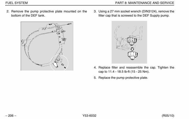
FUEL SYSTEM PART 8: MAINTENANCE AND SERVICE
– 206 – Y53-6032 (R05/10)
2. Remove the pump protective plate mounted on thebottom of the DEF tank.
3. Using a 27 mm socket wrench (DIN3124), remove thefilter cap that is screwed to the DEF Supply pump.
4. Replace filter and reassemble the cap. Tighten thecap to 11.4 - 18.5 lb-ft (15 - 25 Nm).
5. Replace the pump protective plate.
Y53-6032.book Page 206 Monday, May 24, 2010 3:37 PM

PART 8: MAINTENANCE AND SERVICE FUEL SYSTEM
(R05/10) Y53-6032 – 207 –
Steering
Guidelines For Checking A Steering SystemWARNING! A steering system that is not work-ing properly can cause an accident involvingdeath or personal injury. You could lose con-trol of your vehicle if the steering is not ingood order. For driving safety, give your steer-ing gear and components the following visualchecks frequently. Check them especiallyafter trips over rough roads.
• Check tie rod for straightness
• Check draglink clamp for looseness or interference
• Check ball joints and steering U-joints for looseness
• Check steering wheel for excessive freeplay. Checkthe simplest probable causes first:
– Unequal tire pressures
– Loose cap nuts
– Bent tie rod
– Loose wheel bearing
If these checks do not reveal the problem, or if you correctthem and still have a steering problem, take your vehicleto an authorized dealer for evaluation.
Front End Alignment
For driving safety and comfort, and to prolong the life ofyour vehicle, it is important to have proper front end align-ment. Check tire wear frequently. Uneven tire wear is asign that your front end or rear axles may be misaligned.
If you see uneven wear, take your vehicle to a service cen-ter familiar with aligning front ends on Peterbilt vehicles.
Rear Axle Alignment
Continual road shock and load stresses may force yourrear axles out of alignment. If you detect rapid tire wear onthe rear axles, you may have misaligned axles. If you sus-pect you do, have your rear axle alignment checked andadjusted by an authorized dealership.
U-Bolt Tension for Front and Rear Axles
It is important that U-bolts remain tight. Off-highway use ofyour vehicle will cause them to loosen faster. But all vehi-cles need to have their U-bolts checked and tightened
Y53-6032.book Page 207 Monday, May 24, 2010 3:37 PM
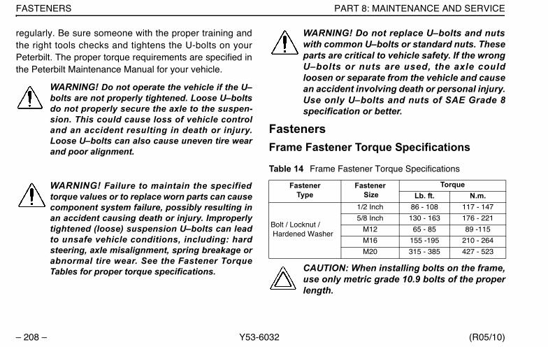
FASTENERS PART 8: MAINTENANCE AND SERVICE
– 208 – Y53-6032 (R05/10)
regularly. Be sure someone with the proper training andthe right tools checks and tightens the U-bolts on yourPeterbilt. The proper torque requirements are specified inthe Peterbilt Maintenance Manual for your vehicle.
WARNING! Do not operate the vehicle if the U–bolts are not properly tightened. Loose U–boltsdo not properly secure the axle to the suspen-sion. This could cause loss of vehicle controland an accident resulting in death or injury.Loose U–bolts can also cause uneven tire wearand poor alignment.
WARNING! Failure to maintain the specifiedtorque values or to replace worn parts can causecomponent system failure, possibly resulting inan accident causing death or injury. Improperlytightened (loose) suspension U–bolts can leadto unsafe vehicle conditions, including: hardsteering, axle misalignment, spring breakage orabnormal tire wear. See the Fastener TorqueTables for proper torque specifications.
WARNING! Do not replace U–bolts and nutswith common U–bolts or standard nuts. Theseparts are critical to vehicle safety. If the wrongU–bolts or nuts are used, the axle couldloosen or separate from the vehicle and causean accident involving death or personal injury.Use only U–bolts and nuts of SAE Grade 8specification or better.
FastenersFrame Fastener Torque Specifications
CAUTION: When installing bolts on the frame,use only metric grade 10.9 bolts of the properlength.
Table 14 Frame Fastener Torque Specifications
FastenerType
Fastener Size
TorqueLb. ft. N.m.
Bolt / Locknut / Hardened Washer
1/2 Inch 86 - 108 117 - 147
5/8 Inch 130 - 163 176 - 221
M12 65 - 85 89 -115
M16 155 -195 210 - 264
M20 315 - 385 427 - 523
Y53-6032.book Page 208 Monday, May 24, 2010 3:37 PM
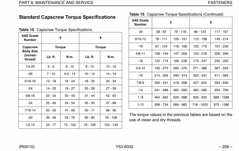
PART 8: MAINTENANCE AND SERVICE FASTENERS
(R05/10) Y53-6032 – 209 –
Standard Capscrew Torque Specifications
The torque values in the previous tables are based on theuse of clean and dry threads.
Table 15 Capscrew Torque Specifications
SAE Grade Number 5 8
Capscrew Body Size (inches-thread)
Torque Torque
Lb. ft. N.m. Lb. ft. N.m.
1/4-20 6 - 9 8 - 12 9 - 12 12 - 16
-28 7 - 10 9.5 - 14 10 - 14 14 - 19
5/16-18 13 - 18 18 - 24 18 - 25 24 - 34
-24 14 - 20 19 - 27 20 - 28 27 - 38
3/8-16 22 - 32 30 - 43 31 - 44 42 - 60
-24 25 - 40 34 - 54 35 - 50 47 - 68
7/16-14 35 - 50 47 - 68 50 - 71 68 - 96
-20 39 - 56 53 - 76 56 - 80 76 - 108
1/2-13 54 - 77 73 - 104 76 - 109 103 - 149
-20 58 - 87 79 - 118 86 - 123 117 - 167
9/16-12 78 - 111 105 - 151 110 - 158 149 - 214
-18 87 - 124 118 - 168 123 - 176 167 - 239
5/8-11 108 - 154 147 - 209 153 - 218 208 - 296
-18 122 - 174 166 - 236 173 - 247 235 - 335
3/4-10 192 - 273 260 - 370 271 - 386 367 - 523
-16 214 - 305 290 - 414 303 - 431 411 - 583
7/8-9 309 - 441 419 - 598 437 - 624 593 - 846
-14 341 - 486 462 - 659 482 - 589 654 - 799
1 -8 464 - 662 629 - 898 656 - 935 889 - 1268
1-12 508 - 724 689 - 982 718 - 1023 973 - 1386
Table 15 Capscrew Torque Specifications (Continued)
SAE Grade Number 5 8
Y53-6032.book Page 209 Monday, May 24, 2010 3:37 PM
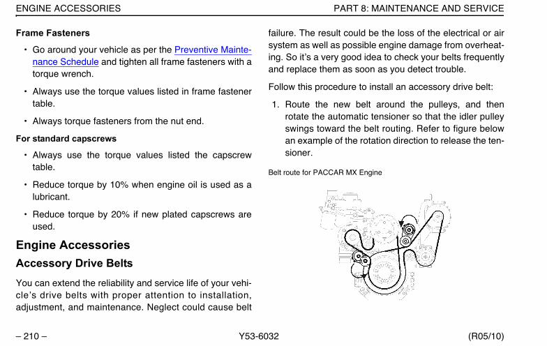
ENGINE ACCESSORIES PART 8: MAINTENANCE AND SERVICE
– 210 – Y53-6032 (R05/10)
Frame Fasteners
• Go around your vehicle as per the Preventive Mainte-nance Schedule and tighten all frame fasteners with atorque wrench.
• Always use the torque values listed in frame fastenertable.
• Always torque fasteners from the nut end.
For standard capscrews
• Always use the torque values listed the capscrewtable.
• Reduce torque by 10% when engine oil is used as alubricant.
• Reduce torque by 20% if new plated capscrews areused.
Engine AccessoriesAccessory Drive BeltsYou can extend the reliability and service life of your vehi-cle’s drive belts with proper attention to installation,adjustment, and maintenance. Neglect could cause belt
failure. The result could be the loss of the electrical or airsystem as well as possible engine damage from overheat-ing. So it’s a very good idea to check your belts frequentlyand replace them as soon as you detect trouble.
Follow this procedure to install an accessory drive belt:
1. Route the new belt around the pulleys, and thenrotate the automatic tensioner so that the idler pulleyswings toward the belt routing. Refer to figure belowan example of the rotation direction to release the ten-sioner.
Belt route for PACCAR MX Engine
Y53-6032.book Page 210 Monday, May 24, 2010 3:37 PM

PART 8: MAINTENANCE AND SERVICE ENGINE ACCESSORIES
(R05/10) Y53-6032 – 211 –
Belt route for Caterpillar Engine
2. Slip the belt around the idler pulley attached to theautomatic tensioner.
3. Release the automatic tensioner.
4. Check the belt alignment on each pulley. The beltmust fall between the flanges of each pulley.
Fan Clutch / FanWARNING! Do not work on the fan with theengine running. The engine fan can engage atany time without warning. Anyone near the fanwhen it turns on could be killed or seriouslyinjured. Before turning on the ignition, be surethat no one is near the fan.
Your truck may be equipped with an On/Off or ViscousFan Drive. Follow these guidelines to check your enginefan:
• Check the fan assembly mounting bolts for tightness.Inspect the fan blades for damage.
On/Off Fan Drives - Check the clutch operation by startingthe engine when it is cold. Idle the engine at about 800RPM. Listen for air leaks. Check that the fan is not work-ing while the engine is warming up. When the clutchengages, note the reading on the vehicle's panel-mountedcoolant temperature gauge. If the fan clutch engages atlow engine temperature or cycles on and off more fre-quently than it should (receives "false signals"), have theproblem corrected at your dealership.
Y53-6032.book Page 211 Monday, May 24, 2010 3:37 PM
AIR INTAKE SYSTEM PART 8: MAINTENANCE AND SERVICE
– 212 – Y53-6032 (R05/10)
Air Intake SystemEngine heat, vibration, and age combine to loosen airintake connections and cause cracks in the tubing andelbows. Leaks in the intake system allow abrasive dust toenter the engine and quickly cause expensive damage.During your daily walk-around inspection, carefully checkall tubing, elbows, clamps, supports, and fasteners forcondition and tightness.
CAUTION: Improper maintenance of the airintake system will allow abrasive dust to enterthe engine which can cause equipment dam-age.
Under normal operating conditions, we recom-mend complete disassembly and cleaning of the air intakesystem annually.
Under severe operating conditions, such as heavy off-highway use, the disassembly and cleaning should bemore frequent. Replace any defective parts. With the pos-sible exception of mounting brackets, don’t repair defec-tive parts.
Air CleanersThe following service information is basic to all air cleanermakes and models.
Service the air cleaner filter elements as specified in thePreventive Maintenance Schedule. If your vehicle isequipped with an optional air inlet restriction indicator, ser-vice the filter elements when the air inlet restriction indica-tor locks in the extreme Up position. Paper elementsrequire care and proper handling because they are criticalto engine service life.
TurbochargerWhen servicing the air intake and exhaust systems on aturbocharged engine, check the items that follow. If youdetect any deficiencies, take the vehicle to an authorizeddealer for servicing. Delay could lead to severe andexpensive damage to your vehicle.
WARNING! The exhaust piping and Diesel Par-ticulate Filter can become extremely hot dur-ing engine operation and can cause death orpersonal injury. Allow adequate cooling timebefore working on or near any part of theexhaust system.
Y53-6032.book Page 212 Monday, May 24, 2010 3:37 PM
PART 8: MAINTENANCE AND SERVICE EXHAUST SYSTEM
(R05/10) Y53-6032 – 213 –
WARNING! If your vehicle becomes disabled,the hot exhaust system could ignite drygrass, brush, spilled fuel, or other materialthat can cause fires which can lead to death,personal injury and property damage. Do notpark or operate your vehicle in areas wherethe hot exhaust system could cause a fire.
CAUTION: This truck is equipped with a dieselparticulate filter in order to meet both noiseand exhaust emissions requirements.Removal or tampering with the unit will notimprove engine performance. Also tamperingis against the rules that are established by theU.S. Code of Federal Regulations. The unitmay only be replaced with an approved part.
WARNING! Do not operate engine with the tur-bocharger intake piping disconnected. A suc-tion is created when the engine is running. Thissuction could draw your hand or anything elsenear it into the impeller fan. You could be killedor seriously injured. Always keep the intake pip-ing connected when you will be running theengine.
CAUTION: Operating the engine with the tur-bocharger intake piping disconnected willallow abrasive dust to enter the engine whichcan cause equipment damage.
• Lubricating System: Check the oil lines, housing, andconnections. Look for leaks, damage, or deterioration.Leaks could mean you have damaged oil lines or oilseals.
• Manifold: With the engine operating, check for leakingmanifold or flange gaskets.
• High Frequency Vibration: Vibration may indicateturbo rotor imbalance. Have your dealer investigatethis immediately.
Exhaust SystemDetails of inspection and maintenance of your exhaustsystem are covered under “Noise Control System” onpage 222.
Anti-lock Braking System (ABS)For details of use and maintenance of your anti-lock sys-tem, see the anti-lock braking system service literaturethat came with your truck.
Y53-6032.book Page 213 Monday, May 24, 2010 3:37 PM

ANTI-LOCK BRAKING SYSTEM (ABS) PART 8: MAINTENANCE AND SERVICE
– 214 – Y53-6032 (R05/10)
Below are some general notes on repairing your anti-lockbraking system:
• The foundation brake system must be in proper work-ing order to ensure the best ABS performance.
• Before welding anywhere on the vehicle, detach theABS ECU connector and all other electronic controlunits.
• Never detach the ECU connector with the ignitionturned on.
• Do not attempt to repair ABS/ASR/ATC electricalcables that are outside the vehicle. Replace faultycables as an assembly.
• When servicing brakes, hubs, or axle, recoat the ABSsensors with anti-seize compound. Make sure thesensor is pushed against the pulse wheel after thehub is reinstalled. On rear axles, the sensor should bepushed fully into the mounting block before reinstall-ing the hub.
• Check ABS wiring harnesses and piping periodicallyfor chafing or other problems. No regular mainte-nance is required on the ABS components.
• During wheel balancing, dyno testing, or any time theignition is on with part of the ABS disconnected, a fail-ure code will be recorded. After servicing or testing ofthe vehicle is completed, clear the failure codes.
If, due to operating conditions, a brake application causeseither wheel on the same axle to begin skidding, wheelspeed sensors immediately signal the anti-lock controllerin the modulator assembly. The controller respondsinstantly by signaling the solenoids in the modulator whichactivate the air valves, reducing application pressure asneeded to prevent the wheels from locking up. If this over-riding correction is effective, application pressure isallowed to build up to the original input.
Any malfunction of the anti-lock system on one or moreaxles will cause the system to fail-safe, and the panel-mounted amber warning light will come on, indicating botha malfunction, and automatic shut-down of the system. Ifthe air system is intact (indicated by the pressuregauges), the service brakes will continue to function nor-mally, but without benefit of the anti-lock feature.
Y53-6032.book Page 214 Monday, May 24, 2010 3:37 PM
PART 8: MAINTENANCE AND SERVICE CAB HEATER-AIR CONDITIONER
(R05/10) Y53-6032 – 215 –
WARNING! Although the brakes will continue tooperate with a malfunction in either circuit, thevehicle should not be operated until the systemis repaired, and both braking circuits, includingall pneumatic and mechanical components, areworking properly. Failure to do so may result indeath or personal injury.
CAUTION: Do not attempt to recycle the anti-lock system until the vehicle has beenbrought to a full stop.
NOTE: If one wheel on any driven axle continuesto slip or spin for approximately 4 seconds, thiswill cause the anti-lock controller for that axle togo into the fail-safe mode, and the warning lightwill give a shutdown signal. In this case, the anti-lock system can be turned back on, and the warn-ing light extinguished, by turning the key switchOFF and ON, after the vehicle has been broughtto a full stop. When the key switch is turned backon, the warning light will illuminate and remain onfor 3 to 5 seconds. This is a built-in function test ofthe warning light.
Cab Heater-Air ConditionerThe combination heater-air conditioner provides comfortfor those in the cab through accurate control of the cabenvironment in all weather conditions. Regular attentionwill help you keep your unit running well.
NOTES:Keep the engine exhaust system and thevehicle’s cab/sleeper ventilation system properlymaintained. It is recommended that the vehicle’sexhaust system and cab/sleeper be inspected
• by a competent technician every 15,000 miles
• whenever a change is noticed in the sound ofthe exhaust system
• whenever the exhaust system, underbody, cabor sleeper is damaged
Y53-6032.book Page 215 Monday, May 24, 2010 3:37 PM
CAB HEATER-AIR CONDITIONER PART 8: MAINTENANCE AND SERVICE
– 216 – Y53-6032 (R05/10)
NOTES:Allow for the proper operation of the vehi-cle ventilation system:
• Keep the inlet grille at the base of the wind-shield clear of snow, ice, leaves, and otherobstructions at all times.
• Keep the exhaust pipe area clear to helpreduce the buildup of exhaust gases under thevehicle.
Perform the following checks every 3 months or 30,000miles / 48,000 km, whichever occurs first:
Heater• Check all heater controls for full-range operation.
• Check hoses, connections, and heater core for condi-tion and leaks.
• Check the drain pan of the fresh air vent for trappedwater before assuming that there is a leak in the heat-ing system.
• If the heater core is leaking, take the vehicle to aPeterbilt dealer for proper heater service or repair.
• Check the heater core for debris blocking the air flow.If the blower is functioning properly, yet the heater isnot operating properly, the heater core may beclogged. Clean the heater core if necessary. If thecondition persists, take the vehicle to a Peterbiltdealer for proper heater service or repair.
Air ConditionerWARNING! The air conditioning system isunder pressure. If not handled properly, itcould explode, causing death or injury to youand can damage your vehicle. Any servicingthat requires depressurizing and rechargingthe air conditioning system must be con-ducted by a qualified technician with the rightfacilities to do the job.
• Check the compressor belt condition and proper ten-sion. Adjust 105 - 125 pounds.
• Check the compressor and drive clutch for noise andvibration. If you find problems, have the systemchecked thoroughly. A malfunctioning clutch usuallyindicates trouble elsewhere in the system.
Y53-6032.book Page 216 Monday, May 24, 2010 3:37 PM
PART 8: MAINTENANCE AND SERVICE CAB HEATER-AIR CONDITIONER
(R05/10) Y53-6032 – 217 –
• Check the evaporator core and condenser core fordebris restricting air flow. Clean if necessary. Smallparticles may be removed with compressed air blownthrough the core in the opposite direction of normal airflow.
WARNING! Wear eye protection any time youblow compressed air. Small particles blown bycompressed air could injure your eyes.
• Check all hoses for kinks, deterioration, chafing, andleaks. Adjust kinked or chafing hoses to eliminaterestrictions and prevent further wear.
• Check all components and connections for refrigerantleaks. If you discover a leak, don’t try to tighten a con-nection. Tightening a connection may cause a worseleak. Have a qualified technician correct the problem.
NOTE: A leaking evaporator or condenser corecannot be repaired; it must be replaced.
• Have the air conditioning system fully inspected annu-ally by your dealer.
Special Precautions
WARNING! Excessive heat may cause your airconditioning system to explode which mayresult in death or personal injury. Never weld,solder, steam clean, or use a blow torch nearany part of the air conditioning system. If arefrigerant leak develops in the presence ofexcessive heat or an open flame, hazardousgases may be generated. These gases maycause illness or death. If the system is leakingrefrigerant
• Stay away from the hot engine until theexhaust manifold has cooled.
• Don’t permit any open flame in the area.Even a match or a cigarette lighter may gen-erate a hazardous quantity of phosgenegas.
• Don’t smoke in the area. Inhaling gaseousrefrigerant through a cigarette may causeillness.
Y53-6032.book Page 217 Monday, May 24, 2010 3:37 PM

APPEARANCE PART 8: MAINTENANCE AND SERVICE
– 218 – Y53-6032 (R05/10)
AppearancePainted Surfaces
CAUTION: Do not aim the water jet directly atdoor locks or hatch. Tape the key holes to pre-vent water from seeping into the lock cylin-ders. Water in lock cylinders should beremoved with compressed air. To preventlocks from freezing in the winter, squirt glyc-erin or lock deicer into the lock cylinders.
• Wash frequently to remove grime and caustic depos-its that may stain the finish. Apply cool or lukewarmwater. You may want to use a mild soap.
• Avoid washing your vehicle in bright sunlight.
WARNING! Handle cleaning agents carefully.Cleaning agents may be poisonous and causedeath or personal injury if swallowed or inhaled.Keep them out of the reach of children.
• Road tar may be removed with a special commercialtar remover or mineral spirits.
• Waxing offers added protection against staining andoxidation. But to allow enough time for your truck’s fin-ish to cure, wait about ninety days after the date ofmanufacture before waxing. Don’t wax in the hot sun.Don’t friction burn the paint with a buffing machine.
Aluminum and Chrome Surfaces• Clean aluminum wheels and bumpers with warm
water.
• Tar remover will get rid of heavy deposits of roadgrime.
• To prevent spotting, wipe aluminum surfaces dry afterwashing.
• Under corrosive conditions, such as driving on saltedroads, clean aluminum parts with steam or high pres-sure water from a hose. A mild soap solution will help.Rinse thoroughly.
• Chrome surfaces are best cleaned with fresh water.Wipe dry to preserve their luster. A commercialchrome cleaner will remove light rust. After cleaning,wax flat surfaces and apply a thin coat of rust preven-tive lubricant around bolts or other fasteners.
Y53-6032.book Page 218 Monday, May 24, 2010 3:37 PM
PART 8: MAINTENANCE AND SERVICE APPEARANCE
(R05/10) Y53-6032 – 219 –
Stainless SteelFollow this procedure to clean and restore the finish ofstainless steel components:
1. In a plastic pail mix 4 tsp of alum (a powder found ingrocery stores or drugstores), with 32 oz. of water(warm water will dissolve alum faster, but cool willwork).
2. Apply the alum/water solution with a pad of steel wool(0000 grade or finer). GENTLY wipe the componentlengthwise; no pressure is necessary.
3. It is the chemical reaction between the carbon steel ofthe wool and the alum solution that cleans the stain-less, not the scrubbing or abrasive action of applica-tion.
4. You may also use any stainless cleaner recom-mended for cleaning boat parts.
Interior
Cleaning Cab Interiors
Peterbilt cab and sleeper interiors are built using a varietyof different materials including fabrics, carpet, polyure-
thane, and painted plastic surfaces. These cleaning pro-cedures will ensure that interior components remain ingood condition for the life of the vehicle.
General Cleaning Guidelines
WARNING!
• •Cleaning agents may contain hazardousagents. Thoroughly read, understand andfollow the manufacturer’s instructions whenusing a cleaning agent to avoid possibledeath, personal injury and property dam-age.
• Handle cleaning agents carefully. Keepthem out of the reach of children. Commer-cial cleaning agents may be poisonous.
CAUTION: To avoid possible property damage
• Do not spray any kind of liquid directly atinstruments or controls. Apply cleaner to arag first and then clean instruments andgauges. Excess fluid may damage the useand function of instruments and gauges.
Y53-6032.book Page 219 Monday, May 24, 2010 3:37 PM
APPEARANCE PART 8: MAINTENANCE AND SERVICE
– 220 – Y53-6032 (R05/10)
• Always test a commercial cleaning agent onan inconspicuous area of the surface to becleaned before using it.
• Never clean interior components withchemicals or solvents such as–Gasoline–Naphtha–Acetone–Turpentine–Benzene–Carbon Tetrachloride–Lacquer Thinner–Nail Polish Remover–Ammonia-based Products–Diesel Exhaust Fluid
• Clean difficult stains such as oil, grease,and mustard as soon as possible. Thelonger a stain goes untreated, the more dif-ficult it is to remove.
• Avoid application of conditioning productscontaining silicones or waxes to the topsurface of the dash panel. This may causeglare that can be a driver distraction.
Interior Trim, Dash Shell, and Instrument Panels
CAUTION: To avoid possible damage to thesecomponents, do not use abrasive cleaners,brushes, chemical solvents or strong deter-gents.
• Use a clean, lint-free cloth.
• Clean with the cloth dampened with a mild soap-and-water solution.
• Remove soap with a clean, damp rag.
• For difficult stains on painted plastic surfaces, such asthe dash shell, use Dupont™ Sontara® cleaner, partnumber PS-3909S. The product is available fromDupont as a presaturated wipe.
Carpet
CAUTION: Do not apply water directly to carpet.Excess water may damage the carpet. Keepcarpet as dry as possible.
• Use a clean, lint-free cloth or clean, soft-fiber brush.
• Clean with the cloth or brush dampened with a mildsoap-and-water solution.
Y53-6032.book Page 220 Monday, May 24, 2010 3:37 PM

PART 8: MAINTENANCE AND SERVICE APPEARANCE
(R05/10) Y53-6032 – 221 –
• Remove soap with a clean, damp rag.
• If a stronger cleaning solution is required, use a foam-type carpet shampoo.
Vinyl and Fabric Upholstery
CAUTION: To avoid possible damage to theupholstery, do not use chemical solvents orstrong detergents on these components.
• Use a clean, lint-free cloth.
• Clean with the cloth dampened with a mild soap-and-water solution.
• Remove soap with a clean, damp rag.
• For difficult stains, use a commercial fabric or vinylcleaner.
Leather Upholstery
CAUTION: To avoid possible damage to theupholstery, do not use oils, varnishes, solvents,abrasive cleaners or shoe polish on these com-ponents.
• Use a clean, lint-free cloth.
• Clean with the cloth dampened with lukewarm water.
• Dry with a clean cloth.
• For difficult stains, use a commercial leather cleaner.
WeatherstrippingOccasionally spray weatherstripping on doors and win-dows with silicone compound to help preserve resiliency.This is especially useful in freezing weather to preventdoors and windows from sticking shut with ice.
ChassisHose dirt and grime from the entire chassis. Then if an oilleak develops, you will be able to detect it easier.
CAUTION: Do not spray the suspension withchemical products or mineral oil; it can causedamage to the bushings.
Storing and Reintroducing Vehicles Into ServiceTo help maintain a vehicle in storage as well as ease itsreintroduction into service, perform the following actionsat least monthly:
Y53-6032.book Page 221 Monday, May 24, 2010 3:37 PM

NOISE CONTROL SYSTEM PART 8: MAINTENANCE AND SERVICE
– 222 – Y53-6032 (R05/10)
• Wash and protect painted and metal surfaces, andalso weatherstripping, as outlined in the preceding“Appearance” information.
• Operate the vehicle to circulate fluids and lubricantsthat have settled to the lowest part of a component.This will provide protection against corrosion on gearsand bearings and keep seals resilient.
Before starting the engine, do the following:
– Check the engine oil level and fill as required.
– Check and maintain batteries as outlined on page195.
– Drain any condensation from the fuel/water sepa-rator, if so equipped.
– Start the engine and bring to normal operatingtemperature:
– Operate the air conditioning system at least 10minutes.
– Drive the vehicle a short distance to allow lubri-cants to circulate in the transmission and axles.
Noise Control SystemNoise Emission WarrantyPeterbilt Motors Company warrants to the first person whopurchases this vehicle for purposes other than resale andto each subsequent purchaser that this vehicle, as manu-factured by Peterbilt Motors Company, was designed, builtand equipped to conform at the time it left Peterbilt’s con-trol with all applicable U.S. EPA Noise Control Regula-tions.
This warranty covers this vehicle as designed, built andequipped by Peterbilt, and is not limited to any particularpart, component or system of the vehicle manufactured byPeterbilt. Defects in design, assembly or in any part, com-ponent or system of the vehicle as manufactured by Peter-bilt, which at the time it left Peterbilt’s control caused noiseemissions to exceed Federal standards, are covered bythis warranty for the life of the vehicle.
Tampering with Noise Control System ProhibitedFederal law prohibits the following acts or the causingthereof:
Y53-6032.book Page 222 Monday, May 24, 2010 3:37 PM

PART 8: MAINTENANCE AND SERVICE NOISE CONTROL SYSTEM
(R05/10) Y53-6032 – 223 –
(1) The removal or rendering inoperative by any personother than for maintenance, repair, or replacement, of anydevice or element of design incorporated into any newvehicle for the purpose of noise control prior to its sale ordelivery to the ultimate purchaser or while it is in use, or(2) the operation of the vehicle after such device or ele-ment of design has been removed or rendered inoperativeby any person.
Among those acts presumed to constitute tampering are
Engine Cooling System
• Removing or rendering inoperative the fan clutch.
• Removing the fan shroud.
Air Intake System
Removing or rendering inoperative the air cleaner / silenc-ers or intake piping.
Exhaust System
• Removing or rendering inoperative the exhaust sys-tem components.
• Inner Fender Shields and Cab Skirts
• Removing shields or skirts.
• Cutting away parts of shields, skirts or damaged orloose portions of shields or skirts.
Fuel System
• Removing or rendering engine speed governor inop-erative, allowing engine speed to exceed manufac-turer’s specifications.
• Removing air signal attenuator on engines equippedwith this device.
Noise Insulating Blankets
• Removing noise insulators from engine block or fromaround the oil pan.
• Cutting holes in, or cutting away part of, noise insula-tors.
• Removing hood-mounted noise insulation.
Engine Electronic Control Unit (ECU)
Modifying ECU parameters.
Y53-6032.book Page 223 Monday, May 24, 2010 3:37 PM
NOISE CONTROL SYSTEM PART 8: MAINTENANCE AND SERVICE
– 224 – Y53-6032 (R05/10)
Inspection & Maintenance Instructions for Noise Control SystemThe following instructions are based on regular inspectionof the noise control system. If, during regular inspection ormaintenance of other systems or components, you findsomething wrong with parts of the noise control system,inspect those parts more frequently to be sure they areperforming up to specification. At the end of this sectionyou will find the Maintenance Log. This is a schedule ofinspection and maintenance intervals for each compo-nent.
WARNING! The exhaust piping and Diesel Par-ticulate Filter can become extremely hot dur-ing engine operation and can cause death orpersonal injury. Allow adequate cooling timebefore working on or near any part of theexhaust system.
Exhaust System
WARNING! If your vehicle becomes disabled,the hot exhaust system could ignite drygrass, brush, spilled fuel, or other materialthat can cause fires which can lead to death,personal injury and property damage. Do notpark or operate your vehicle in areas wherethe hot exhaust system could cause a fire.
Manifold
Check for exhaust leaks and condition of gaskets.Replace any blown gaskets. Use a torque wrench tocheck all cap-screws, including those at the flanges. Referto the engine manufacturer’s service manual for propertightening sequence and torque values.
Joints and Clamps
Check for leaks, and tighten as necessary. Check for dete-rioration or dents in pipes and clamps which could allowexhaust to escape.
Y53-6032.book Page 224 Monday, May 24, 2010 3:37 PM

PART 8: MAINTENANCE AND SERVICE NOISE CONTROL SYSTEM
(R05/10) Y53-6032 – 225 –
Piping
Check for rust, corrosion, and damage. If piping is perfo-rated at any point, temporary patching or lagging isacceptable until you can have permanent repairs made.On turbocharged engines check joints at the flanges andmounting brackets for tightness.
Diesel Particulate Filter (DPF)
NOTE: Use only exact replacement componentsin exhaust systems. Certain components containintegral catalytic converters essential for compli-ance with EPA emission standards. Using a non-compliant component as a replacement couldviolate these standards and also void the emis-sion system’s warranty.
Check clamps and mounting brackets for security. Checkinternal baffling for security. You can do this by listening forrattling sounds while tapping the unit with a rubber malletor revving the engine up and down through its normaloperating range. Check the DPF for rust and corrosion.
Exhaust Tail Pipe(s)
Check the mounting security. Tighten as necessary. Themiter cut at the tip of the pipe must be facing the rear ofthe truck. Do not modify the end of the pipe in any way.
Fan Shroud
WARNING! Do not work on the fan with theengine running. The engine fan can engage atany time without warning. Anyone near the fanwhen it turns on could be killed or seriouslyinjured. Before turning on the ignition, be surethat no one is near the fan.
Check all fasteners for tightness. Check for stress cracksin the shroud. Make sure the shroud is adjusted so that itdoes not touch the fan blades.
Hood Insulation Blanket
Fasteners
Check all fasteners for condition and security. Repair orreplace any broken or defective fasteners.
Y53-6032.book Page 225 Monday, May 24, 2010 3:37 PM
NOISE CONTROL SYSTEM PART 8: MAINTENANCE AND SERVICE
– 226 – Y53-6032 (R05/10)
Blanket
Check for chafing, tears, etc. Patch it if necessary. Findthe cause of the damage. If any component or accessoryis causing wear or damage and can’t be relocated, putreinforcing pads on the blanket at the site of wear.
Engine Mounted Noise Insulators
Fasteners
Check for condition and security. How you do this willdepend on the method of attaching the noise insulators onthe engine and around the oil pan (bolts, snap fasteners,or straps). Tighten loose fasteners; repair or replace anyworn or damaged fasteners.
Insulators
Check insulators around fasteners and stress points,especially where they may be affected by engine vibra-tion. Repair any cracked or damaged mounting points.Use suitable reinforcing plates to ensure that the insula-tors will remain in position.
Inner Fender Shields and Cab Skirts
Fasteners
Check all fasteners for security, especially the self-tappinghex head screws. Remove and replace any loose rivets.
Shields and Skirts
• Check shields and skirts for cracks at mounting andstress points. Check fender shields for tire marks,worn spots, or damage from objects thrown from tiretreads. You can repair cracked or damaged fiberglassfender shields with fiberglass and resin.
• If you find damage at a fastening point, you can gainadditional strength by installing a suitable reinforcingplate. This plate should be drilled to accept a rivet andlaminated to the shield with fiberglass and resin.
• Check cab skirts, sills, and brackets for overall condi-tion and repair them as necessary. Damaged rubberfender shields or cab skirting cannot be repaired. Youwill need to replace it.
Your authorized dealership can perform all of thesechecks and repairs or replacements.
Y53-6032.book Page 226 Monday, May 24, 2010 3:37 PM
PART 8: MAINTENANCE AND SERVICE NOISE CONTROL SYSTEM
(R05/10) Y53-6032 – 227 –
Air Intake System• Do all checks and maintenance chores listed in this
manual under Engine Air Intake System and AirCleaner (See Index).
• Check the induction tubing, elbow connections,clamps, brackets, and fasteners for deterioration,cracks, and security. If you find an air leak anywherebetween the air cleaner and the engine, repair thatleak immediately.
CAUTION: Air leaks cause excessive noiseand may result in serious damage to theengine. If you do not repair them the enginedamage won’t be covered by your warranty.Repair all air leaks as soon as you find them.
Y53-6032.book Page 227 Monday, May 24, 2010 3:37 PM

NOISE CONTROL SYSTEM PART 8: MAINTENANCE AND SERVICE
– 228 – Y53-6032 (R05/10)
Table 16 Noise Control System Maintenance LogsCOMPONENT RECOMMENDED
INTERVAL(MILES)
DATE &R.O. NUMBER
REPAIRFACILITY &LOCATION
WORK PERFORMED DATE &R.O. NUMBER
REPAIRFACILITY &LOCATION
WORK PERFORMED
Exhaust System Rout-ing Integrity 25,000
ShuttersShrouds 25,000
Hood InsulationBlanket 10,000
Engine-Mounted Hose InsultatorsFasteners
10,000
Inner Fender Shields 50,000
Cab SkirtFasteners 50,000
Air Intake System Integrity Element 5,000
Clutch-Type FanDrive 10,000
Y53-6032.book Page 228 Monday, May 24, 2010 3:37 PM

PART 9: VEHICLE IDENTIFICATION NUMBERS
(R05/10) Y53-6032 – 229 –
PART 9: VEHICLE IDENTIFICATION NUMBERS
Each vehicle completed by Peterbilt Motors Companyuses a Vehicle Identification Number (VIN) that containsthe model year designation of your Peterbilt. The practiceis in compliance with 49 CFR 565, Code of Federal Regu-lations.
All Peterbilt vehicles are identified by a 17–digit VehicleIdentification Number (VIN). This unique numeral and let-ter combination identifies the manufacturer, the modelyear it was built, and other vehicle attributes. The VIN is incompliance with 49CFR565, Code of Federal Regula-tions. As an example, the model year and assembly plantare designated by a letter in the tenth and eleventh char-acter positions (see 4 and 5 below).
EXAMPLE VIN: 1XP9D2X96XD345678
1XP 9D2X9 6 X D 345678
1 2 3 4 5 6
VIN characteristics
1 Manufacturer Identifier
2 Vehicle Attributes
3 Check Digit
4 Model Year
5 Assembly Plant
6 Serial/Chassis number
Model Year Codes
9 2009
A 2010
B 2011
C 2012
D 2013
0 (ZERO) Glider Kit
Y53-6032.book Page 229 Monday, May 24, 2010 3:37 PM

FEDERAL SAFETY STANDARD CERTIFICATION LABEL PART 10: CONSUMER INFORMATION
– 230 – Y53-6032 (R05/10)
PART 10: CONSUMER INFORMATION
Federal Safety Standard Certification LabelThe National Highway Traffic Safety Administration regu-lations require a label certifying compliance with FederalSafety Standards, for United States and U.S. Territories,be affixed to each motor vehicle and prescribe where suchlabel may be located.
This certification label, which indicates the date of manu-facture and other pertinent information, is located on theleft hand cab door post.
How To Order PartsWhen you need replacement parts for your Peterbilt vehi-cles, contact your nearest authorized Peterbilt dealer, whomay be located from the “Peterbilt Authorized U.S. andCanadian Dealers” listing (Cat. No. 5212).
When you order, it is IMPORTANT than you have the fol-lowing information ready:
• Your name and address.• Serial number of the truck.• The name of the part you need.• The name and number of the component for which
the part is required.• The quantity of parts you need.• How you want your order shipped.
NHTSA Consumer InformationIf you believe that your vehicle has a defect which couldcause a crash or could cause injury or death, you shouldimmediately inform the National Highway Traffic SafetyAdministration (NHTSA) in addition to notifying PeterbiltMotors Company.
If NHTSA receives similar complaints, it may open aninvestigation, and if it finds that a safety defect exists in agroup of vehicles, it may order a recall and remedy cam-
02955
Y53-6032.book Page 230 Monday, May 24, 2010 3:37 PM

PART 10: CONSUMER INFORMATION CANADIAN CONSUMER INFORMATION
(R05/10) Y53-6032 – 231 –
paign. However, NHTSA cannot get involved in individualproblems between you, your dealer, and Peterbilt MotorsCompany.
Contacting NHTSA is possible through telephone, wriittenmail and email. NHTSA also has a website where you caninput you comments directly to them onthe web. Pleaseuse any of the four ways to contact NHTSA:
Canadian Consumer InformationCanandian customers, who wish to report a safety-relateddefect to Transport Canada, Defect Investigations andRecalls, may telephone the toll free hotline 1-800-333-0510, or contact Transport Canada by mail at:
Transport Canada, ASFADPlace de Ville Tower C330 Sparks StreetOttawa ON K1A 0N5
For additional road safety information, please visit theRoad Safety website at
http://www.tc.gc.ca/roadsafety/menu.htm
Environmental ProtectionWARNING! Diesel engine exhaust and someof its constituents are known to the State ofCalifornia to cause cancer, birth defects, andother reproductive harm. Other chemicals inthis vehicle are also known to the State of Cal-ifornia to cause cancer, birth defects or otherreproductive harm. This warning requirementis mandated by California law (Proposition 65)and does not result from any change in themanner in which Peterbilt trucks are manufac-tured.
Some of the ingredients in engine oil, hydraulic oil, trans-mission and axle oil, engine coolant, diesel fuel, air condi-tioning refrigerant (R12, R134a, and PAG oil), batteries,
Toll Free 888-327-4236 (800-4249153 TTY)
8:00 am to 10:00 pm ET Monday-Friday
Office of Defects Investigations/CRD
NVS-216
1200 New Jersey Ave SE.
Washington, D.C. 20590
www www.safercar.gov
Y53-6032.book Page 231 Monday, May 24, 2010 3:37 PM
STATE OF CALIFORNIA PART 10: CONSUMER INFORMATION
– 232 – Y53-6032 (R05/10)
etc., may contaminate the environment if spilled or not dis-posed of properly. Contact your local government agencyfor information concerning proper disposal.
State of CaliforniaCalifornia Proposition 65 WarningDiesel engine exhaust and some of its constituents areknown to the State of California to cause cancer, birthdefects, and other reproductive harm.
Other chemicals in this vehicle are also known to theState of California to cause cancer, birth defects or otherreproductive harm.
Battery posts, terminals, and related accessories containlead and lead compounds, chemicals known to the Stateof California to cause cancer and reproductive harm.Wash hands after handling.
California Vehicle Code, Section 9951 - Disclosure of Recording DeviceYour vehicle may be equipped with one or more recordingdevices commonly referred to as “event data recorders(EDR)” or “sensing and diagnostic modules (SDM)”. If youare involved in an accident, the device(s) may have theability to record vehicle data that occurred just prior toand/or during the accident.
For additional information on your rights associated withthe use of this data, contact
the California Department of Motor Vehicles - LicensingOperations Division
or
http://www.dmv.ca.gov/pubs/vctop/d03_6/vc9951.htm
Y53-6032.book Page 232 Monday, May 24, 2010 3:37 PM

PART 11: SUBJECT INDEX
(R05/10) Y53-6032 – 233 –
PART 11: SUBJECT INDEX
AAnti-lock brakes 109, 213Appearance 218Appliances in the Cab 72BBattery
compartment cover 201electrolyte 196recharging 196slow battery charging 198
Belts, seat 77Brake
operation 109Brake system
Electronic Stability Control 111truck & tractor 109
CCap Nut Torque Specifications 187Cleaning the vehicle 218Consumer Information 230Controls
Air Horn 41Air Suspension Deflate Switch (Dump Valve) 45Brakesaver 49Cigarette Lighter 58
Cruise Control Switch 48Dome Light Switch 44Electric Horn 40Engine Brake 49Engine Fan Switch 46Fifth Wheel Lock (Slider Adjustment) Switch 52Fog Lights Switch 44Hazard Flasher 39Headlamps 42Headlights 42Heater-Air Conditioning Controls 54Interaxle Differential Lock Switch 50Manual Override 42Mirror Heat Switch 47Panel Light Knob 43Parking Brake Valve and Trailer Air Supply Valve 53Power Mirror Switch 47Tilt- Telescoping Steering Column 41Trailer Brake Hand Valve 40Turn Signal and Indicator Lights 35Windshield Wipers and Washers 37
Cooling systemcoolant level 194extended life coolant 191, 193temperature 65topping up 193
Y53-6032.book Page 233 Monday, May 24, 2010 3:37 PM

PART 11: SUBJECT INDEX
– 234 – Y53-6032 (R05/10)
DDash 14DEF 67, 205Defogging/defrosting system 57Deisel Exhaust Fluid 205Deisel Exhaust Fluid Tank 205Door lock 218Driver Information Display 30Driver’s Checklist 88Driving
vehicle inspection 88EElectrical system
batteries 197battery charging 198jumper cables 199
Electrolyte 196Emission, Diesel Exhaust Fluid Lamp 26Emissions, Diesel Particulate Filter (DPF) 25Emissions, Malfunction Indicator Lamp 26Engine
overspeed 141Engine Warmup 95Environmental Protection 231Exhaust fumes 144FFederal motor vehicle safety standards 5Federal Safety Standard Certification Label 230
Frame Fastener Torque Specifications 208GGauges and Displays 59
Air Application Gauge 63Air Filter Restriction Indicator or Gauge 70Engine Oil Pressure Gauge 64Fuel Gauge 66Manifold Pressure Gauge 69Primary And Secondary Air Pressure Gauges 63Pyrometer 70Speedometer / Odometer 30Speedometer-Message Center 60Tachometer 61Voltmeter 70Warning Lights and Buzzers 17Water Temperature Gauge 65
Glove Compartment 59GVWR - gross vehicle weight rating 179, 183HHeadlamp
adjustment 201Heater and air conditioner 57HEST warning lamp 128High beam 36High Exhaust System Temperature (HEST) warning lamp 127hood anti-blowdown device 12Hood Tilting 11
Y53-6032.book Page 234 Monday, May 24, 2010 3:37 PM
PART 11: SUBJECT INDEX
(R05/10) Y53-6032 – 235 –
JJumper cables 199KKeys 7Keys and Locks
Ignition Switch 41LLubrication
Axle 169–170coasting 141Steering Gear 171Transmission 165–??types and brands 161Universal Joint 171Wheel Bearing 170
Lubrication Index 163Luggage Compartment(s) 71MMaintenance Schedule 143Menu Control Switch (MCS) 15, 17Mirrors 71NNavigation System 73Noise Control System 222PParked Regeneration 131parked regeneration 51
Parking brakebrake system, operation 53, 119use 143
RRear suspension
fasteners (standard) 208Refrigerator 72Regeneration Switch 16, 51Restraint Systems 75
Inspection 83Komfort-Lok® Feature 79Shoulder Belt 76Sleeper Bunk Restraints 80Tether Belts 82
SSafe vehicle operation 88Safety stands 144Seat 75Seat adjustment 75Seats 75Servicing Specific Systems
Air Intake System 212Air System 188Anti-lock Braking System (ABS) 213Brake Adjustment 173Cab Heater-Air Conditioner 215Electrical 195Engine Accessories 210
Y53-6032.book Page 235 Monday, May 24, 2010 3:37 PM

PART 11: SUBJECT INDEX
– 236 – Y53-6032 (R05/10)
Engine Cooling System 191Fasteners 208Steering 207Tires, Wheels, And Rims 177Transmission And Drive Train 203
Shifting gears 141, 142Standard Capscrew Torque Specifications 209Starting and Operating 93
Anti-Lock Braking System 108Automated Transmission 105Auxiliary Transmission 105Bobtail Brake Proportioning System 117Brake Safety and Emergency 117Digital Message Center 117Driving Bobtail or with an Unloaded Trailer 126Driving With Deflated Air Springs 139Dual Range (Two Speed) Axles 103Idling the Engine 97If Your Vehicle Must Be Towed 105Interaxle Differential 101Manually Releasing Spring Brakes 121Operating the Clutch 99Overheated Brakes 118Parking Brakes and Their Use 118Retarders 125Setting Ride Height 136Shifting The Transmission 99Starting Procedure
Cold Temperature 94
Normal Temperature 93Stopping The Engine 134Trailer Air Supply Valve 120
Suspensionfasteners, torque 208
TTachometer 142Tire Load and Inflation Tables 182towing 106Transmission
lubrication 165warmup 97
UUnits of Measure 35VVehicle
driving 88Vehicle inspections 88Vehicle weight rating 183WWarning Light / Indicator Symbols 20Warning Light Symbols table 20Warning Light/Indicator Symbol Descriptions 23Wheels and tires
load rating 179replacement 177
Windshield washer reservoir 38
Y53-6032.book Page 236 Monday, May 24, 2010 3:37 PM

PART 11: SUBJECT INDEX
(R05/10) Y53-6032 – 237 –
Numerics49 CFR 565, Code of Federal Regulations 229
Y53-6032.book Page 237 Monday, May 24, 2010 3:37 PM
Related Documents