Many elements © Don Thomas, 2014, used with permission 18-545 — Advanced Digital Design ECE Department Lecture Quick Introduction to SystemVerilog: Sequental Logic L03 with credit to G. Larson

Welcome message from author
This document is posted to help you gain knowledge. Please leave a comment to let me know what you think about it! Share it to your friends and learn new things together.
Transcript
Many elements © Don Thomas, 2014, used with permission
!
18-545 — Advanced Digital Design ECE Department
Lecture
Quick Introduction to SystemVerilog: Sequental Logic
L03
with
cre
dit t
o G
. Lar
son
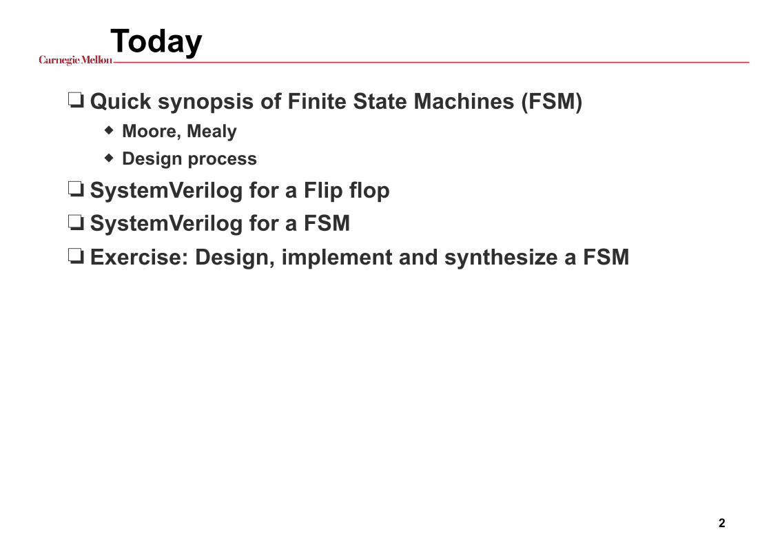
Today❏ Quick synopsis of Finite State Machines (FSM)
◆ Moore, Mealy ◆ Design process
❏ SystemVerilog for a Flip flop ❏ SystemVerilog for a FSM ❏ Exercise: Design, implement and synthesize a FSM
2
18-240 L9 —
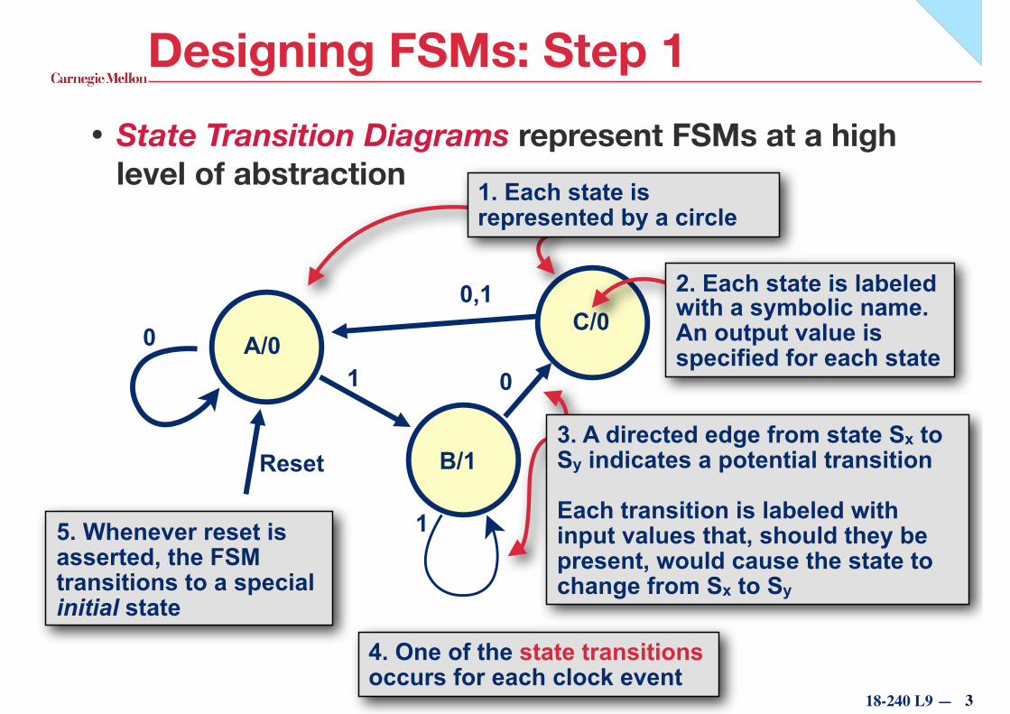
1. Each state is represented by a circle
Designing FSMs: Step 1• State Transition Diagrams represent FSMs at a high
level of abstraction
5. Whenever reset is asserted, the FSM transitions to a special initial state
Reset
3
4. One of the state transitions occurs for each clock event
A/0
B/1
C/02. Each state is labeled with a symbolic name. An output value is specified for each state
0
1
01
0,1
3. A directed edge from state Sx to Sy indicates a potential transition
Each transition is labeled with input values that, should they be present, would cause the state to change from Sx to Sy
18-240 L9 —
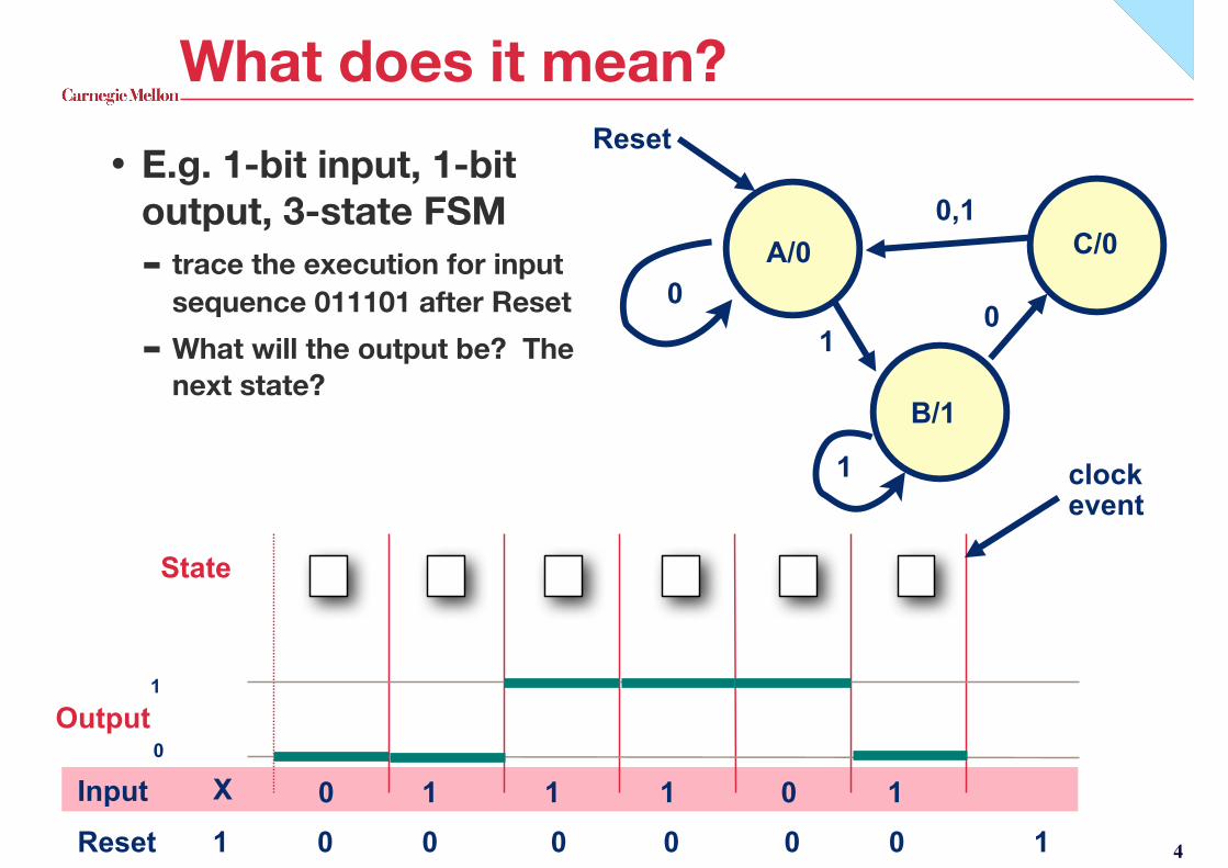
What does it mean?• E.g. 1-bit input, 1-bit
output, 3-state FSM - trace the execution for input
sequence 011101 after Reset - What will the output be? The
next state?
Output
0 1 111 0
1
0
State
clock event
Input
A A B B B C
Reset 1 0 0 0 0 0 0 1
X
4
0
1
1
0,1
B/1
C/00
Reset
A/0
18-240 L9 —
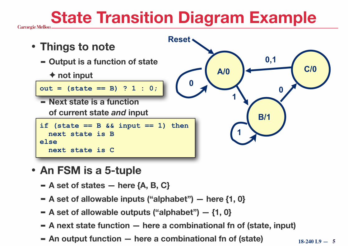
State Transition Diagram Example• Things to note
- Output is a function of state ✦ not input
- Next state is a function of current state and input
• An FSM is a 5-tuple - A set of states — here {A, B, C}
- A set of allowable inputs (“alphabet”) — here {1, 0} - A set of allowable outputs (“alphabet”) — {1, 0}
- A next state function — here a combinational fn of (state, input)
- An output function — here a combinational fn of (state) 5
0
1
1
0,1
B/1
C/00
Reset
A/0
if (state == B && input == 1) then next state is B else next state is C
out = (state == B) ? 1 : 0;
18-240 L9 —
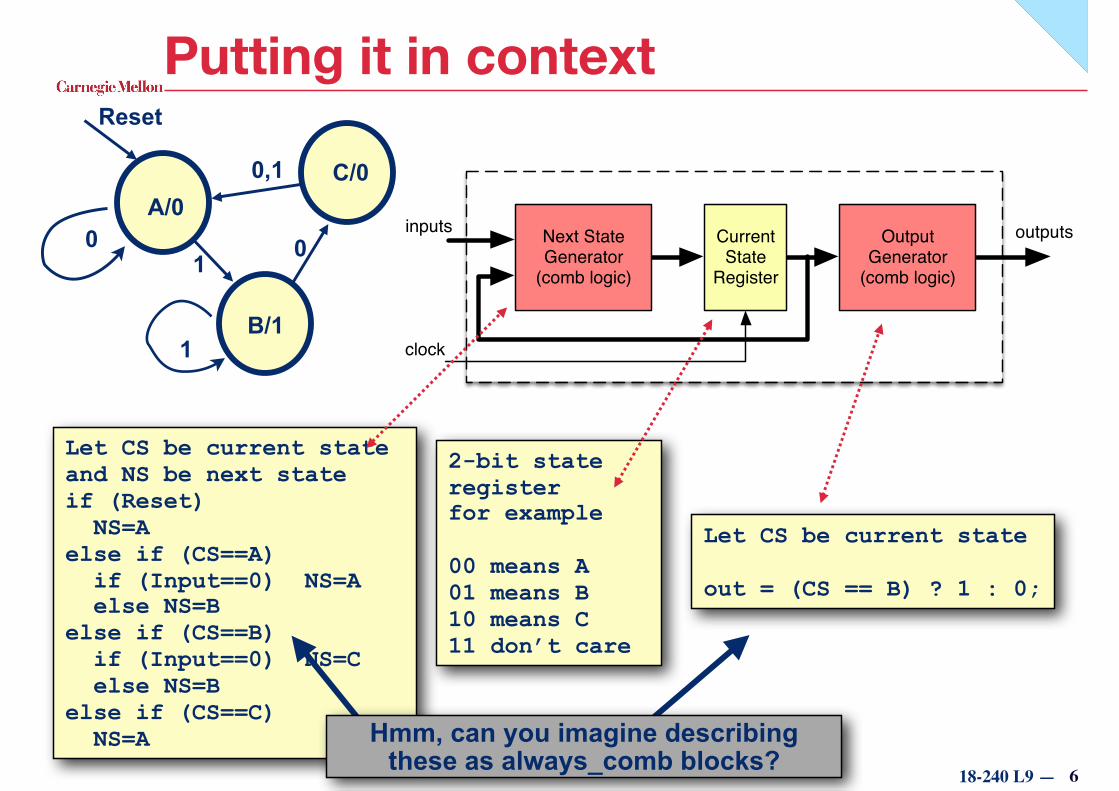
Next State Generator
(comb logic)
Current State
Register
Output Generator
(comb logic)
inputs
clock
outputs
Putting it in context
0
1
1
0,1
B/1
C/0
0
Reset
A/0
2-bit state register for example
00 means A 01 means B 10 means C 11 don’t care
Let CS be current state and NS be next state if (Reset) NS=A else if (CS==A) if (Input==0) NS=A else NS=B else if (CS==B) if (Input==0) NS=C else NS=B else if (CS==C) NS=A
Let CS be current state
out = (CS == B) ? 1 : 0;
6
Hmm, can you imagine describing these as always_comb blocks?
18-240 L9 —
Next State Generator
(comb logic)
Current State
Register
Output Generator
(comb logic)inputs
clock
outputs
Moore vs. Mealy Machines
7
the only difference
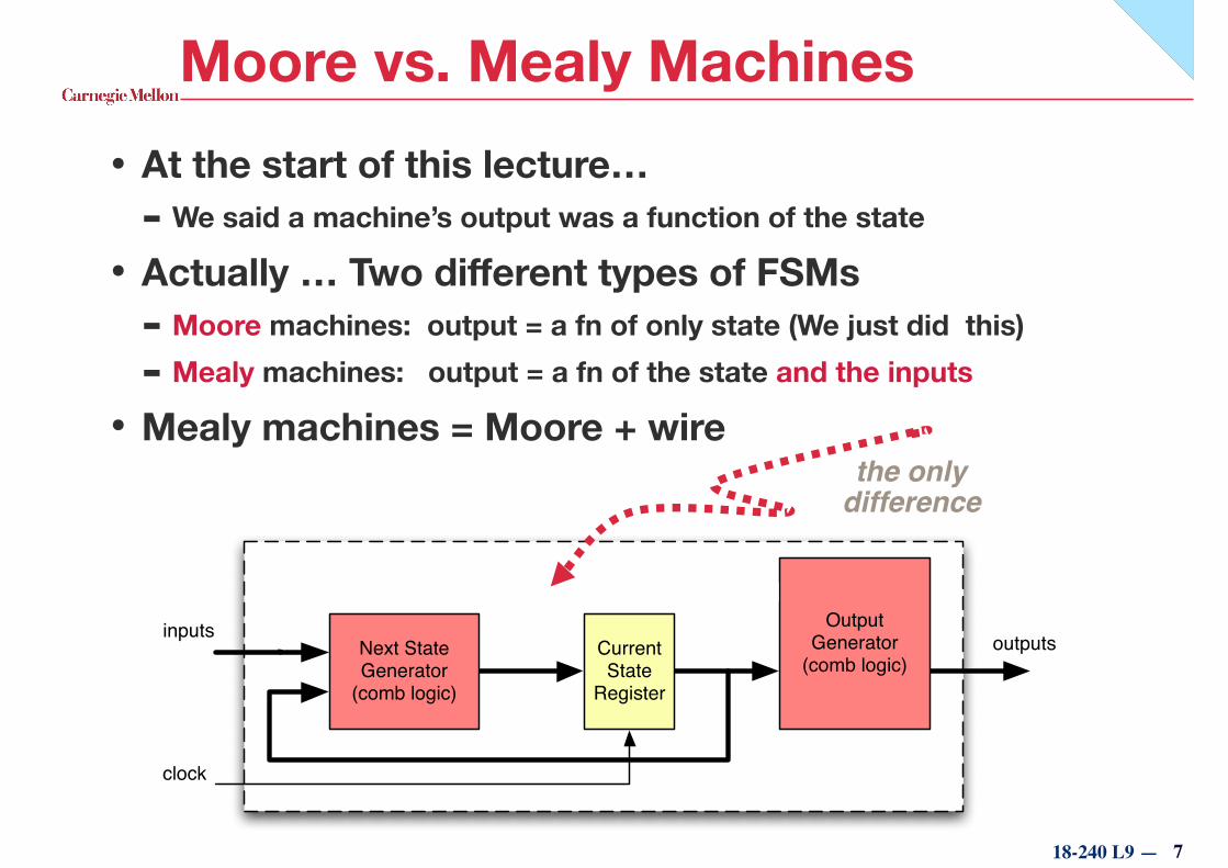
• At the start of this lecture… - We said a machine’s output was a function of the state
• Actually … Two different types of FSMs - Moore machines: output = a fn of only state (We just did this)
- Mealy machines: output = a fn of the state and the inputs
• Mealy machines = Moore + wire
18-240 L9 —
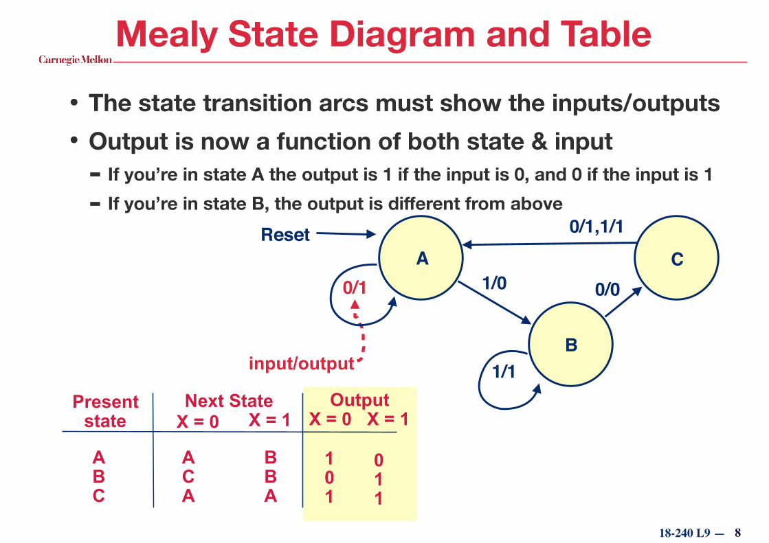
Mealy State Diagram and Table
• The state transition arcs must show the inputs/outputs • Output is now a function of both state & input
- If you’re in state A the output is 1 if the input is 0, and 0 if the input is 1 - If you’re in state B, the output is different from above
Present state
Next State Output X = 0 X = 1X = 0 X = 1
A B C
A C A
B B A
1 0 1
0 1 1
0/0
1/1
0/1 1/0
0/1,1/1A
B
CReset
input/output
8

18-240 L9 —
Mealy Output Notation• Mealy outputs are a function of state and inputs
• Placing a truth table in each state is a bit clumsy - Though less confusing for new students
• As the transitions already have input specifications, we reuse them to describe outputs
9
A
B
CReset
In X
Out0 11 0
In X
Out0 11 1
In X
Out0 01 1
0
1
10
BE CAREFUL: Mealy notation is confusing! You don’t have to actually take the transition for the output to occur

18-240 L9 —
Example: Series Recognizer
Moore State Transition Diagram Mealy State Transition Diagram
INPUT 0 0 0 0 1 0 1 0 1 1 0 1…
OUTPUT 0 0 0 0 1 0 1 0 1 0 0 1…
s? /0
R
s0 /0
0
s01 /1
1
1 0
01
s0s?
R 0/00/0
1/11/0
10
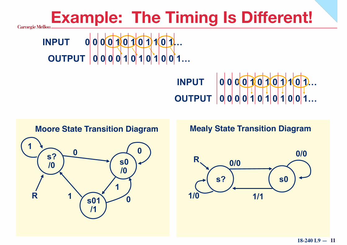
• Let’s do one example in both Moore and Mealy - Want a series recognizer FSM that outputs a 1 every time it detects
sequence ‘01’ in input stream
18-240 L9 —
Example: The Timing Is Different!INPUT 0 0 0 0 1 0 1 0 1 1 0 1…
OUTPUT 0 0 0 0 1 0 1 0 1 0 0 1…
INPUT 0 0 0 0 1 0 1 0 1 1 0 1…
OUTPUT 0 0 0 0 1 0 1 0 1 0 0 1…
11
Moore State Transition Diagram Mealy State Transition Diagram
s? /0
R
s0 /0
0
s01 /1
1
1 0
01
s0s?
R 0/00/0
1/11/0
18-240 L9 —
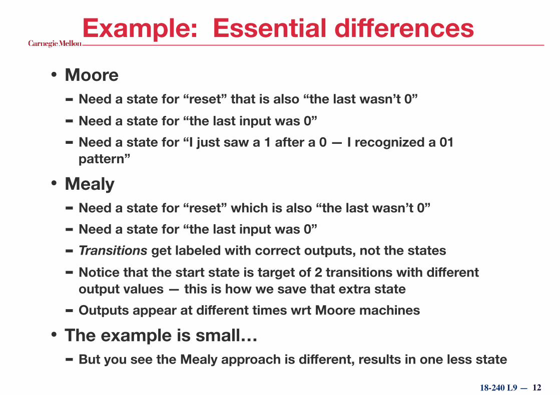
Example: Essential differences• Moore
- Need a state for “reset” that is also “the last wasn’t 0”
- Need a state for “the last input was 0” - Need a state for “I just saw a 1 after a 0 — I recognized a 01
pattern”
• Mealy - Need a state for “reset” which is also “the last wasn’t 0”
- Need a state for “the last input was 0”
- Transitions get labeled with correct outputs, not the states
- Notice that the start state is target of 2 transitions with different output values — this is how we save that extra state
- Outputs appear at different times wrt Moore machines
• The example is small… - But you see the Mealy approach is different, results in one less state
12
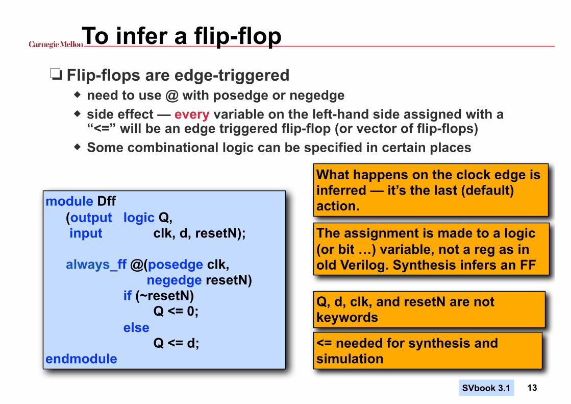
To infer a flip-flop❏ Flip-flops are edge-triggered
◆ need to use @ with posedge or negedge ◆ side effect — every variable on the left-hand side assigned with a
“<=” will be an edge triggered flip-flop (or vector of flip-flops) ◆ Some combinational logic can be specified in certain places
module Dff (output logic Q, input clk, d, resetN);
always_ff @(posedge clk, negedge resetN)
if (~resetN) Q <= 0; else Q <= d; endmodule
What happens on the clock edge is inferred — it’s the last (default) action.
Q, d, clk, and resetN are not keywords
<= needed for synthesis and simulation
13
The assignment is made to a logic (or bit …) variable, not a reg as in old Verilog. Synthesis infers an FF
SVbook 3.1
18-240 L2 —
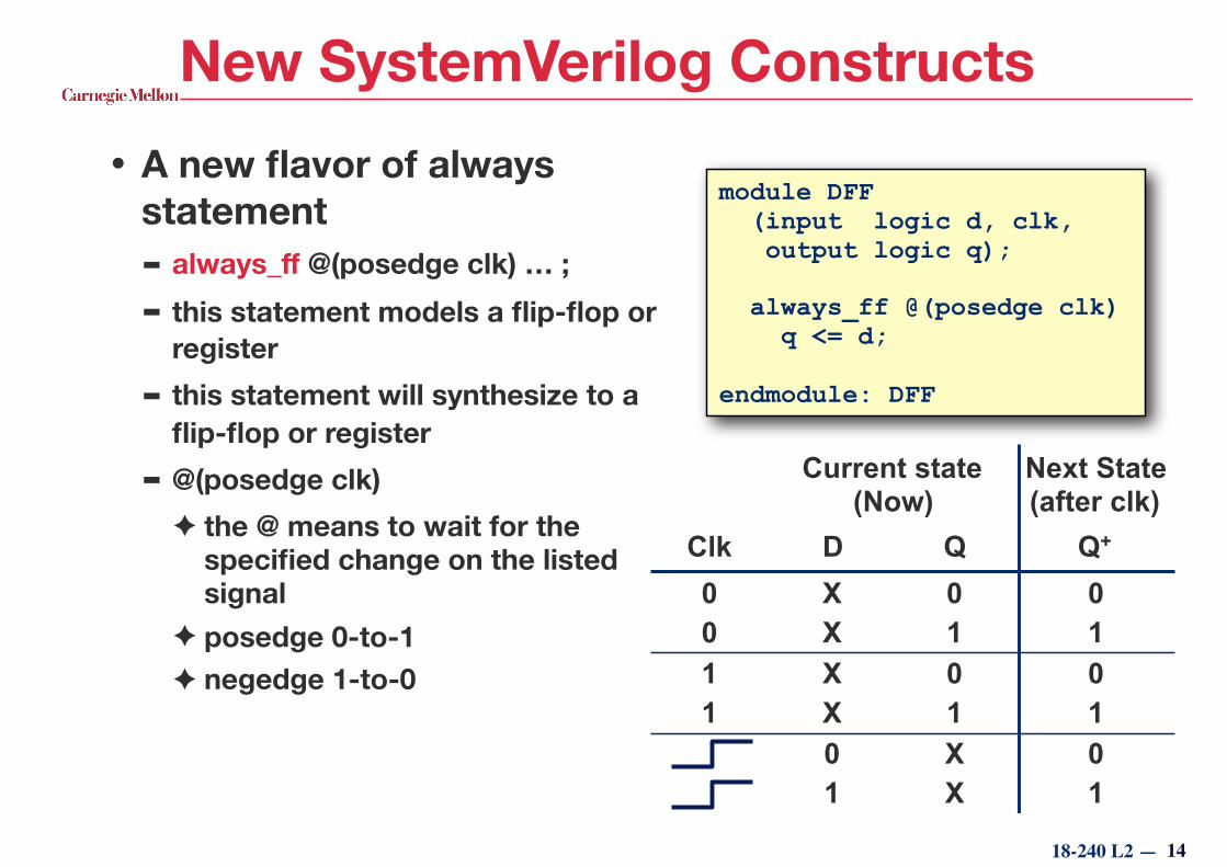
New SystemVerilog Constructs• A new flavor of always
statement - always_ff @(posedge clk) … ;
- this statement models a flip-flop or register
- this statement will synthesize to a flip-flop or register
- @(posedge clk) ✦ the @ means to wait for the
specified change on the listed signal
✦ posedge 0-to-1 ✦ negedge 1-to-0
14
module DFF (input logic d, clk, output logic q);
always_ff @(posedge clk) q <= d;
endmodule: DFF
Current state (Now)
Next State (after clk)
Clk D Q Q+
0 X 0 00 X 1 11 X 0 01 X 1 1
0 X 01 X 1
18-240 L2 —
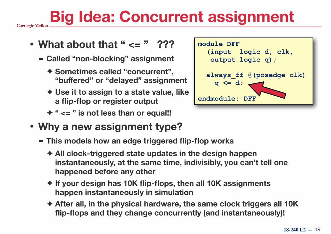
Big Idea: Concurrent assignment• What about that “ <= ” ???
- Called “non-blocking” assignment ✦ Sometimes called “concurrent”,
“buffered” or “delayed” assignment ✦ Use it to assign to a state value, like
a flip-flop or register output ✦ “ <= ” is not less than or equal!!
• Why a new assignment type? - This models how an edge triggered flip-flop works
✦ All clock-triggered state updates in the design happen instantaneously, at the same time, indivisibly, you can’t tell one happened before any other
✦ If your design has 10K flip-flops, then all 10K assignments happen instantaneously in simulation
✦ After all, in the physical hardware, the same clock triggers all 10K flip-flops and they change concurrently (and instantaneously)!
15
module DFF (input logic d, clk, output logic q);
always_ff @(posedge clk) q <= d;
endmodule: DFF
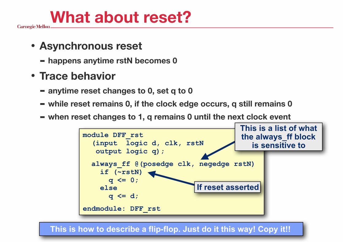
module DFF_rst (input logic d, clk, rstN output logic q);
always_ff @(posedge clk, negedge rstN) if (~rstN) q <= 0; else q <= d;
endmodule: DFF_rst
What about reset?• Asynchronous reset
- happens anytime rstN becomes 0
• Trace behavior - anytime reset changes to 0, set q to 0
- while reset remains 0, if the clock edge occurs, q still remains 0
- when reset changes to 1, q remains 0 until the next clock eventThis is a list of what the always_ff block
is sensitive to
This is how to describe a flip-flop. Just do it this way! Copy it!!
If reset asserted
18-240 L2 —
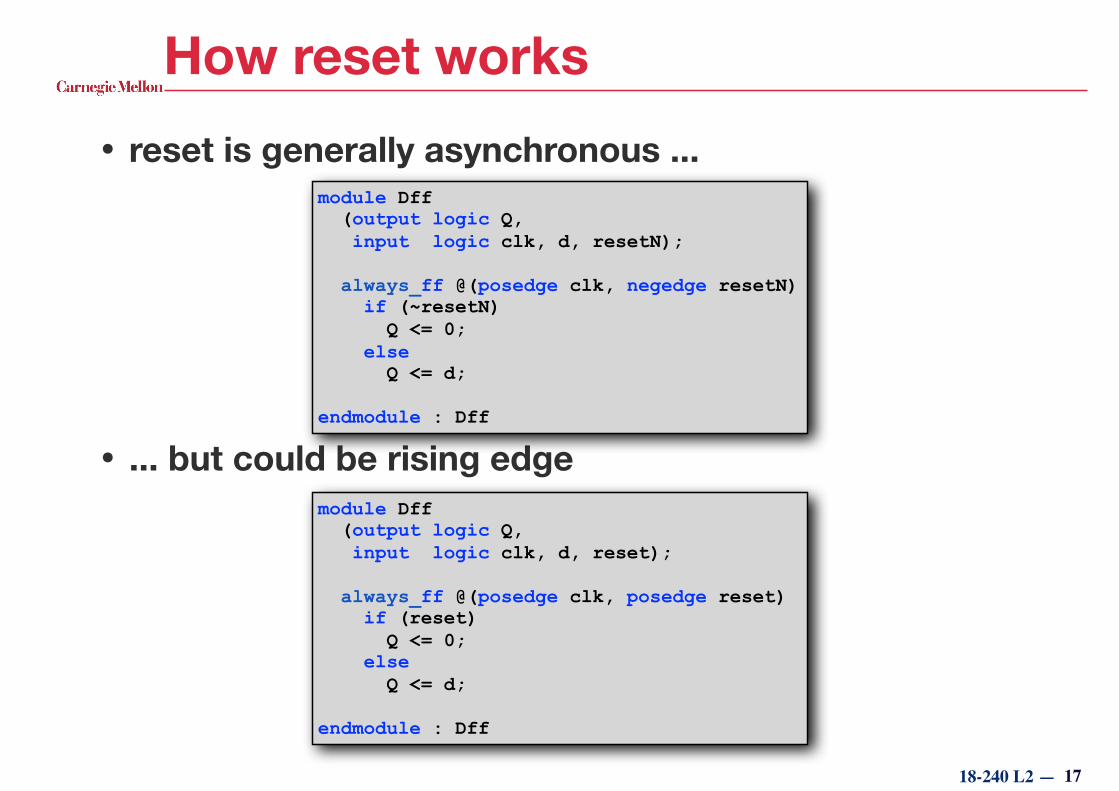
How reset works• reset is generally asynchronous ...
• ... but could be rising edge
17
module Dff (output logic Q, input logic clk, d, resetN);
always_ff @(posedge clk, negedge resetN) if (~resetN) Q <= 0; else Q <= d;
endmodule : Dff
module Dff (output logic Q, input logic clk, d, reset);
always_ff @(posedge clk, posedge reset) if (reset) Q <= 0; else Q <= d;
endmodule : Dff
18-240 L2 —
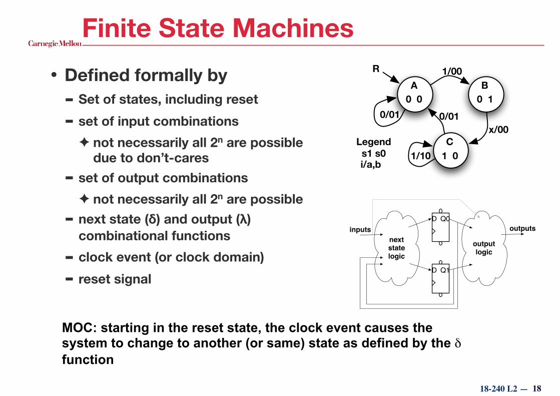
Finite State Machines• Defined formally by
- Set of states, including reset
- set of input combinations ✦ not necessarily all 2n are possible
due to don’t-cares - set of output combinations
✦ not necessarily all 2n are possible - next state (δ) and output (λ)
combinational functions
- clock event (or clock domain)
- reset signal
MOC: starting in the reset state, the clock event causes the system to change to another (or same) state as defined by the δ function
18
0 0 0 1
1 0
A
C
B
R 1/00
1/10
0/010/01
s1 s0Legend
i/a,b
x/00
D Q0
D Q1
next statelogic
output logic
inputs outputs
18-240 L2 —
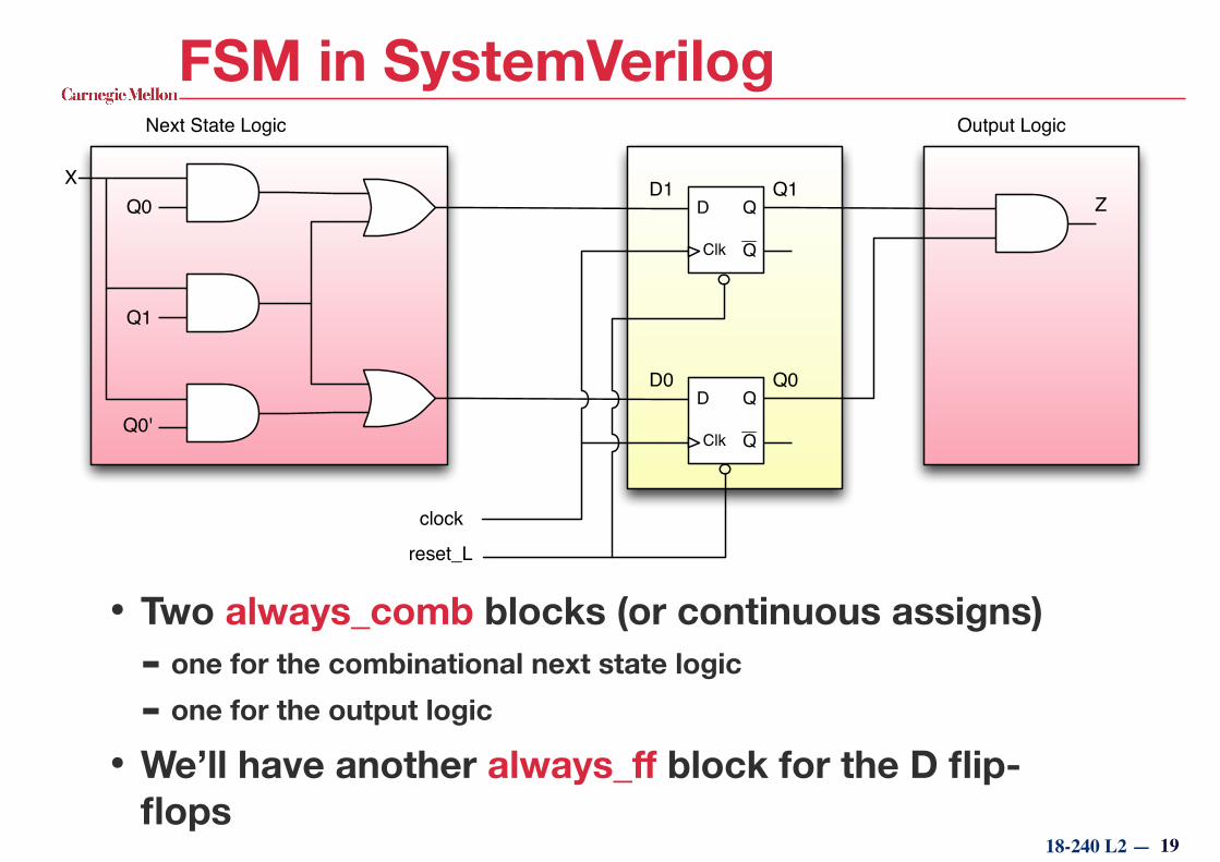
FSM in SystemVerilog
• Two always_comb blocks (or continuous assigns) - one for the combinational next state logic
- one for the output logic
• We’ll have another always_ff block for the D flip-flops
19
D
Clk
Q
Q
D
Clk
Q
Q
Q0
Q1
Q0'
X
Next State Logic
D1
D0
clockreset_L
Q1
Q0
Z
Output Logic

Explicit FSM Style• Done here as 3
blocks - The sequential part:
generates current state (cs) from the next state (ns) synchronously
- The next state generator: combinational logic to create the next state inputs (D1, D0) from the current state and input (x)
- The output generator: combinational logic to create the output (z) from the current state
Called explicit FSM style because everything is explicitly defined: state register, output logic, next state logic, and state assignment
module myFSM2 (input logic clk, rstN, x, output logic z);
logic [1:0] ns, cs; always_ff @(posedge clk, negedge rstN) if (~rstN) cs <= 0; else cs <= ns;
always_comb begin ns[1] = cs[1] & x | cs[0] & x; ns[0] = cs[1] & x | ~cs[0] & x; end
assign z = cs[1] & cs[0];
endmodule: myFSM2
18-240 L2 —
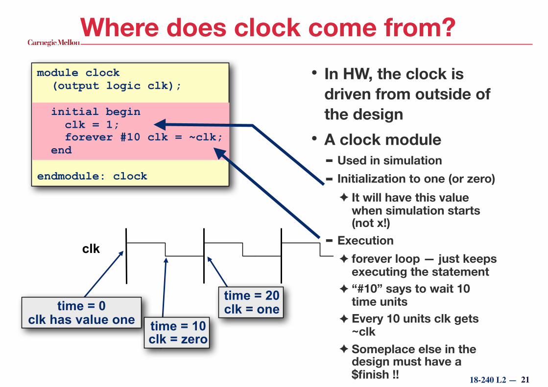
module clock (output logic clk);
endmodule: clock
Where does clock come from?• In HW, the clock is
driven from outside of the design
• A clock module - Used in simulation - Initialization to one (or zero)
✦ It will have this value when simulation starts (not x!)
- Execution ✦ forever loop — just keeps
executing the statement ✦ “#10” says to wait 10
time units ✦ Every 10 units clk gets
~clk ✦ Someplace else in the
design must have a $finish !!
initial begin clk = 1; forever #10 clk = ~clk; end
clk
21
time = 0 clk has value one
time = 20 clk = one
time = 10 clk = zero
enum — enumerate for state encoding
22
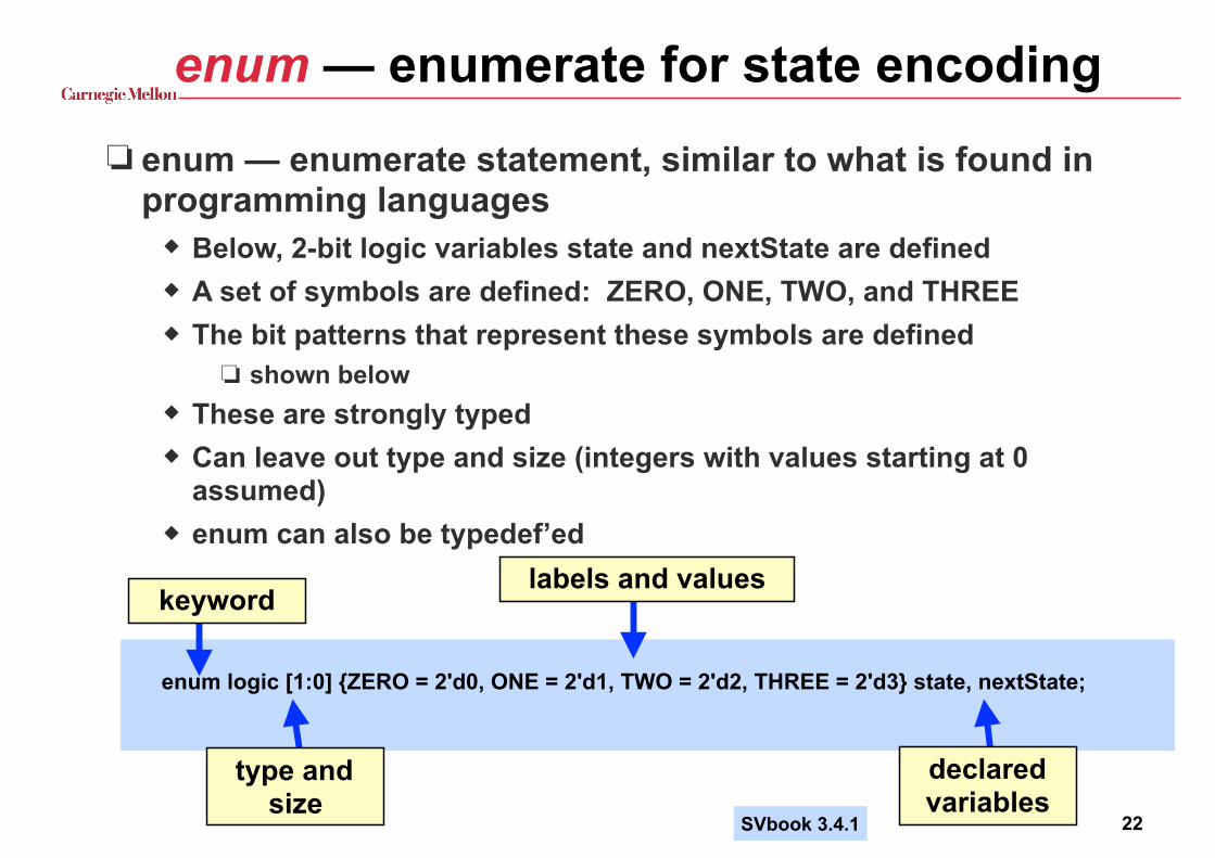
❏ enum — enumerate statement, similar to what is found in programming languages
◆ Below, 2-bit logic variables state and nextState are defined ◆ A set of symbols are defined: ZERO, ONE, TWO, and THREE ◆ The bit patterns that represent these symbols are defined
❏ shown below ◆ These are strongly typed ◆ Can leave out type and size (integers with values starting at 0
assumed) ◆ enum can also be typedef’ed
enum logic [1:0] {ZERO = 2'd0, ONE = 2'd1, TWO = 2'd2, THREE = 2'd3} state, nextState;
keyword
type and size
labels and values
declared variables
SVbook 3.4.1
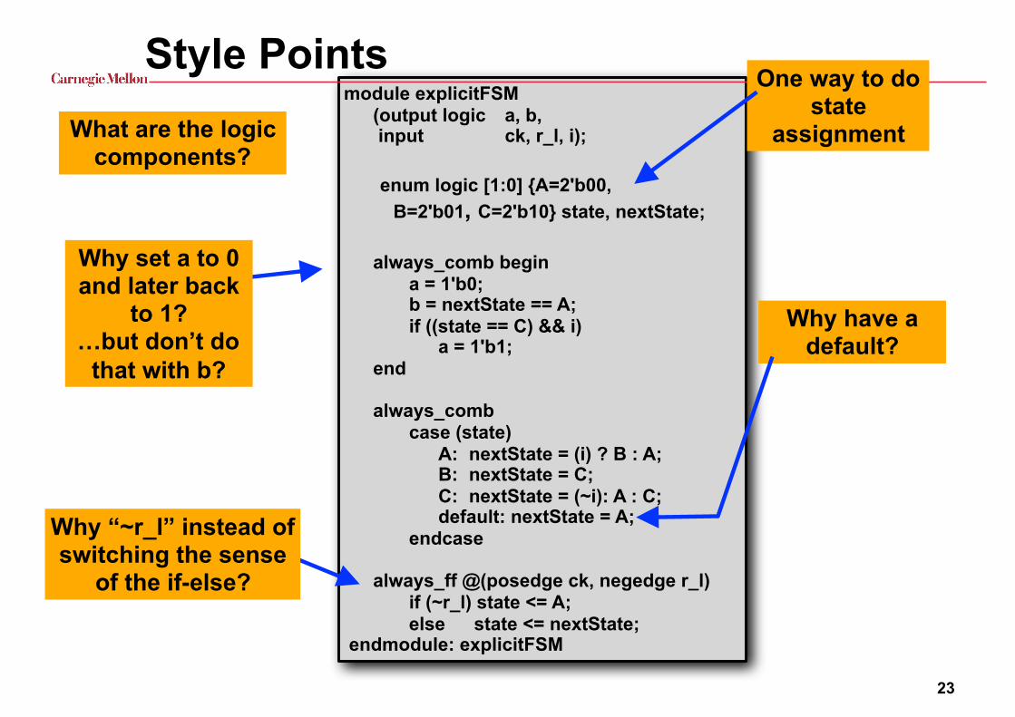
module explicitFSM (output logic a, b, input ck, r_l, i);
enum logic [1:0] {A=2'b00, B=2'b01, C=2'b10} state, nextState;
always_comb begin a = 1'b0; b = nextState == A; if ((state == C) && i) a = 1'b1; end
always_comb case (state) A: nextState = (i) ? B : A; B: nextState = C; C: nextState = (~i): A : C; default: nextState = A; endcase always_ff @(posedge ck, negedge r_l) if (~r_l) state <= A; else state <= nextState; endmodule: explicitFSM
Style PointsWhat are the logic
components?
Why have a default?
One way to do state
assignment
23
Why set a to 0 and later back
to 1? …but don’t do
that with b?
Why “~r_l” instead of switching the sense
of the if-else?
module explicitFSM (output logic a, b, input ck, r_l, i);
enum logic [1:0] {A=2'b00, B=2'b01, C=2'b10} state, nextState;
always_comb begin a = 1'b0; b = nextState == A; if ((state == C) && i) a = 1'b1; end
always_ff @(posedge ck, negedge r_l) if (~r_l) state <= A; else case (state) A: state <= (i) ? B : A; B: state <= C; C: state <= (~i): A : C; default: state <= A; endcase endmodule: explicitFSM
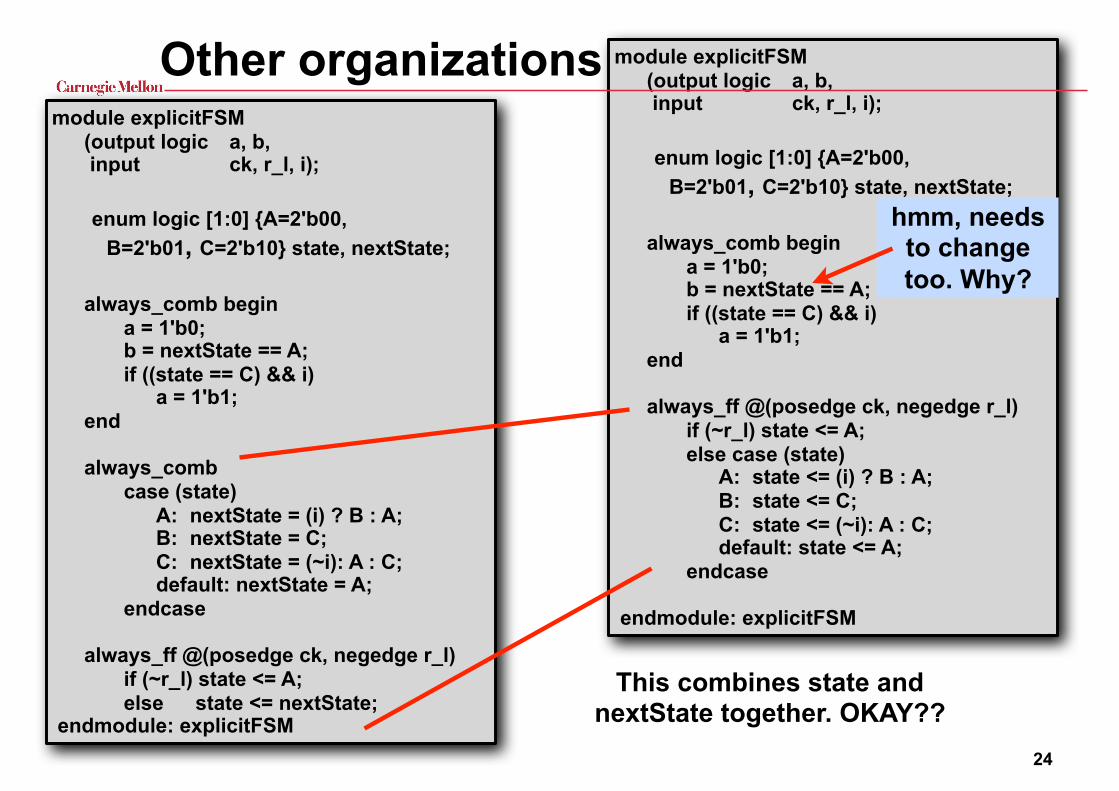
Other organizations
24
module explicitFSM (output logic a, b, input ck, r_l, i);
enum logic [1:0] {A=2'b00, B=2'b01, C=2'b10} state, nextState;
always_comb begin a = 1'b0; b = nextState == A; if ((state == C) && i) a = 1'b1; end
always_comb case (state) A: nextState = (i) ? B : A; B: nextState = C; C: nextState = (~i): A : C; default: nextState = A; endcase always_ff @(posedge ck, negedge r_l) if (~r_l) state <= A; else state <= nextState; endmodule: explicitFSM
This combines state and nextState together. OKAY??
hmm, needs to change too. Why?

Combining parts of an explicit fsm❏ Potential problem
◆ combining the output logic with the state update
◆ OK with a Mealy machine?
◆ OK with a Moore machine?
25
module explicitFSM (output logic a, b, input ck, r_l, i);
enum logic [1:0] {A=2'b00, B=2'b01, C=2'b10} state, nextState;
always_comb begin a = 1'b0; b = nextState == A; if ((state == C) && i) a = 1'b1; end
always_comb case (state) A: nextState = (i) ? B : A; B: nextState = C; C: nextState = (~i): A : C; default: nextState = A; endcase always_ff @(posedge ck, negedge r_l) if (~r_l) state <= A; else state <= nextState; endmodule: explicitFSM
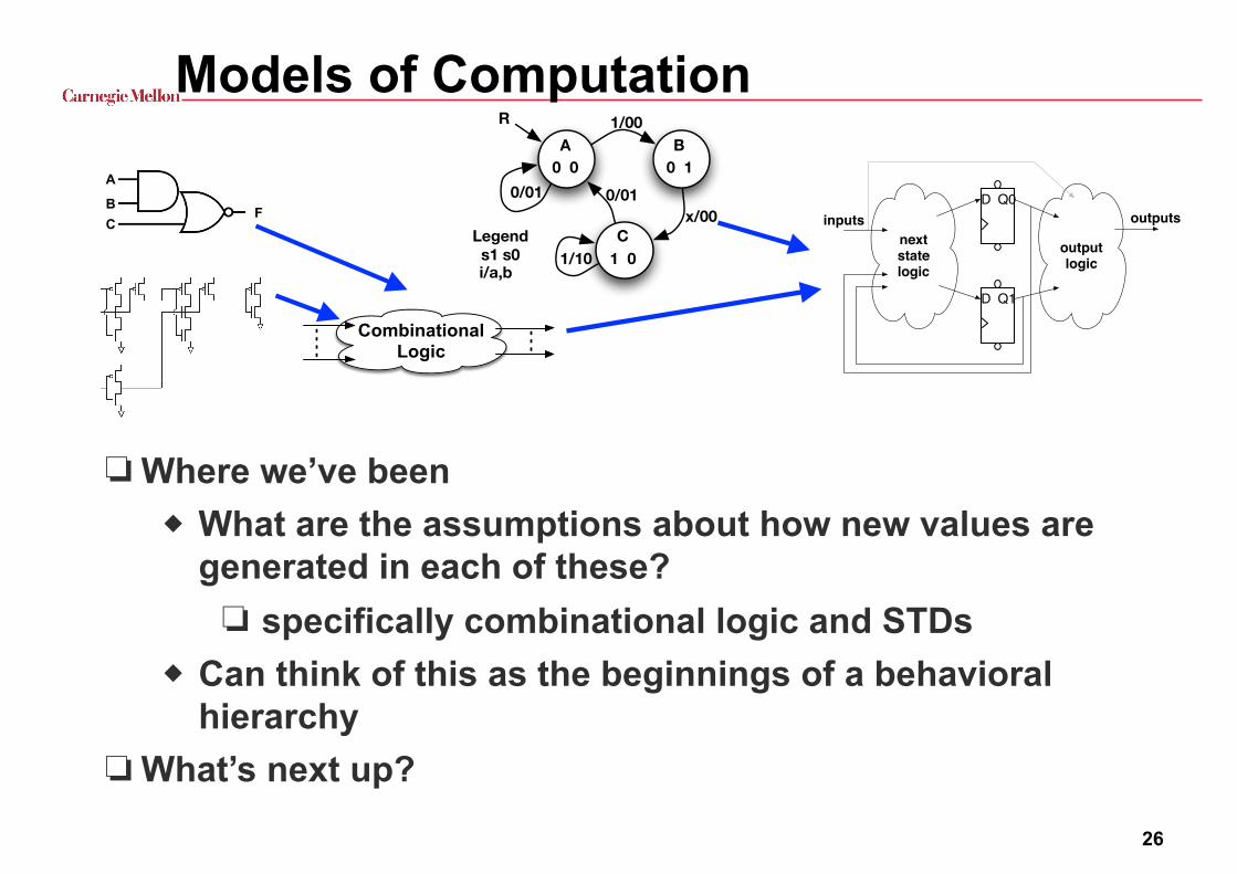
Models of Computation
❏ Where we’ve been ◆ What are the assumptions about how new values are
generated in each of these? ❏ specifically combinational logic and STDs
◆ Can think of this as the beginnings of a behavioral hierarchy
❏ What’s next up?
26
A
F B C
CombinationalLogic
0 0 0 1
1 0
A
C
B
R 1/00
1/10
0/010/01
s1 s0Legend
i/a,b
x/00D Q0
D Q1
next statelogic
output logic
inputs outputs
Related Documents