www.rosemount.com ¢00825-0100-46908¤ Quick Installation Guide 00825-0100-4690, Rev FA April 2013 Rosemount 2088 and 2090 Start End Step 1: Mount the Transmitter Step 2: Set the Jumpers Step 3: Connect the Wiring and Power Step 4: Verify Configuration Step 5: Trim the Transmitter Safety Instrumented Systems Product Certifications Rosemount 2088, 2090P, and 2090F Pressure Transmitters with 4-20 mA HART and 1-5 Vdc HART Low Power Protocol

Quick Installation Guide Rosemount 2088, 2090P, And 2090F Pressure Transmitters With 4-20 mA HART and 1-5 Vdc HART Low Power Protocol
Jan 01, 2016
Quick Installation Guide Rosemount 2088, 2090P, And 2090F Pressure Transmitters With 4-20 mA HART and 1-5 Vdc HART Low Power Protocol
Welcome message from author
This document is posted to help you gain knowledge. Please leave a comment to let me know what you think about it! Share it to your friends and learn new things together.
Transcript

www.rosemount.com
¢00825-0100-46908¤
Quick Installation Guide00825-0100-4690, Rev FAApril 2013 Rosemount 2088 and 2090
Start
End
Step 1: Mount the Transmitter
Step 2: Set the Jumpers
Step 3: Connect the Wiring and Power
Step 4: Verify Configuration
Step 5: Trim the Transmitter
Safety Instrumented Systems
Product Certifications
Rosemount 2088, 2090P, and 2090F Pressure Transmitters
with 4-20 mA HART and 1-5 Vdc HART Low Power Protocol
4690 Rev FA.fm Page 1 Monday, April 15, 2013 8:11 AM
Quick Installation Guide00825-0100-4690, Rev FA
April 2013Rosemount 2088 and 2090
4690 Rev FA.fm Page 2 Monday, April 15, 2013 8:11 AM
© 2013 Rosemount Inc. All rights reserved. All marks property of owner. Rosemount and the Rosemount logotype are registered trademarks of Rosemount Inc.
Emerson Process ManagementRosemount Division8200 Market BoulevardChanhassen, MN USA 55317T (US) (800) 999-9307T (Intnl) (952) 906-8888F (952) 949-7001
Emerson Process Management GmbH & Co. OHGArgelsrieder Feld 382234 WesslingGermanyT 49 (8153) 9390F49 (8153) 939172
Emerson Process Management Asia Pacific Private Limited1 Pandan CrescentSingapore 128461T (65) 6777 8211F (65) 6777 0947/65 6777 0743
Beijing Rosemount Far East Instrument Co., LtdNo. 6 North Street,Hepingli, Dong Cheng DistrictBeijing 100013, ChinaT (86) (10) 6428 2233F (86) (10) 6422 8586
IMPORTANT NOTICE
This installation guide provides basic guidelines for the Rosemount 2088 and 2090 transmitters. It does not provide instructions for configuration, diagnostics, maintenance, service, troubleshooting, Explosion-proof, Flameproof, or intrinsically safe (I.S.) installations.
Refer to the Rosemount 2088/2090 reference manual (document number 00809-0100-4690) for more instruction and low power output. This manual is also available electronically on www.rosemount.com.
WARNING
Explosions could result in death or serious injury:
Installation of this transmitter in an explosive environment must be in accordance with the appropriate local, national, and international standards, codes, and practices. Please review the approvals section of the Rosemount 2088/2090 manual for any restrictions associated with a safe installation.
• Before connecting a HART-based communicator in an explosive atmosphere, make sure the instruments in the loop are installed in accordance with intrinsically safe or non-incendive field wiring practices.
• In an Explosion-proof/Flameproof installation, do not remove the transmitter covers when power is applied to the unit.
Process leaks may cause harm or result in death • Use appropriately rated sanitary clamps and gaskets during installation. • The maximum working pressure of the clamp and gasket must be greater than or
equal to the working pressure range of the transmitter.
Electrical shock can result in death or serious injury• Avoid contact with the leads and terminals. High voltage that may be present on leads
can cause electrical shock.
2
Quick Installation Guide00825-0100-4690, Rev FAApril 2013 Rosemount 2088 and 2090
4690 Rev FA.fm Page 3 Monday, April 15, 2013 8:11 AM
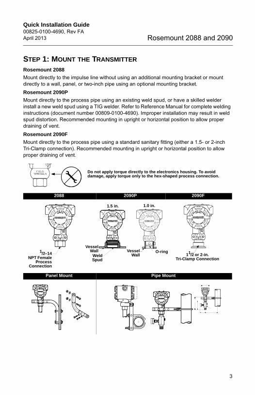
STEP 1: MOUNT THE TRANSMITTER
Rosemount 2088
Mount directly to the impulse line without using an additional mounting bracket or mount directly to a wall, panel, or two-inch pipe using an optional mounting bracket.
Rosemount 2090P
Mount directly to the process pipe using an existing weld spud, or have a skilled welder install a new weld spud using a TIG welder. Refer to Reference Manual for complete welding instructions (document number 00809-0100-4690). Improper installation may result in weld spud distortion. Recommended mounting in upright or horizontal position to allow proper draining of vent.
Rosemount 2090F
Mount directly to the process pipe using a standard sanitary fitting (either a 1.5- or 2-inch Tri-Clamp connection). Recommended mounting in upright or horizontal position to allow proper draining of vent.
Do not apply torque directly to the electronics housing. To avoid damage, apply torque only to the hex-shaped process connection.
2088 2090P 2090F
Panel Mount Pipe Mount
1/2–14NPT Female
ProcessConnection
VesselWall
WeldSpud
1.5 in. 1.0 in.
O-ringVesselWall 11/2 or 2-in.
Tri-Clamp Connection
3

Quick Installation Guide00825-0100-4690, Rev FA
April 2013Rosemount 2088 and 2090
4690 Rev FA.fm Page 4 Monday, April 15, 2013 8:11 AM
STEP 1 CONTINUED...
Liquid Flow Applications
1. Place taps to the side of the line.2. Mount beside or below the taps.
Gas Flow Applications
1. Place taps in the top or side of the line.2. Mount level or above the taps.
Steam Flow Applications
1. Place taps to the side of the line.2. Mount beside or below the taps.
3. Fill impulse lines with water.
4
Quick Installation Guide00825-0100-4690, Rev FAApril 2013 Rosemount 2088 and 2090
4690 Rev FA.fm Page 5 Monday, April 15, 2013 8:11 AM
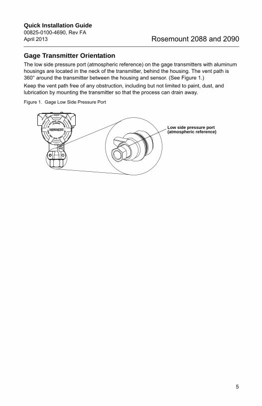
Gage Transmitter OrientationThe low side pressure port (atmospheric reference) on the gage transmitters with aluminum housings are located in the neck of the transmitter, behind the housing. The vent path is 360° around the transmitter between the housing and sensor. (See Figure 1.)
Keep the vent path free of any obstruction, including but not limited to paint, dust, and lubrication by mounting the transmitter so that the process can drain away.
Figure 1. Gage Low Side Pressure Port
Low side pressure port (atmospheric reference)
5
Quick Installation Guide00825-0100-4690, Rev FA
April 2013Rosemount 2088 and 2090
4690 Rev FA.fm Page 6 Monday, April 15, 2013 8:11 AM
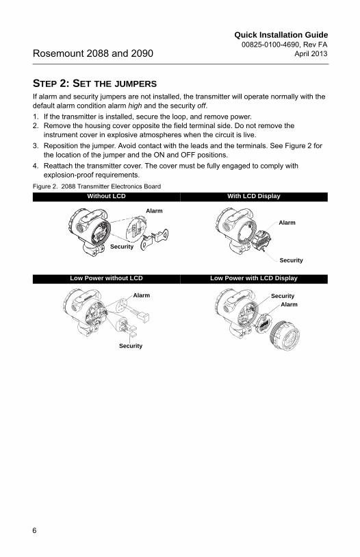
STEP 2: SET THE JUMPERSIf alarm and security jumpers are not installed, the transmitter will operate normally with the default alarm condition alarm high and the security off.
1. If the transmitter is installed, secure the loop, and remove power.2. Remove the housing cover opposite the field terminal side. Do not remove the
instrument cover in explosive atmospheres when the circuit is live.
3. Reposition the jumper. Avoid contact with the leads and the terminals. See Figure 2 for the location of the jumper and the ON and OFF positions.
4. Reattach the transmitter cover. The cover must be fully engaged to comply with explosion-proof requirements.
Figure 2. 2088 Transmitter Electronics Board
Without LCD With LCD Display
Low Power without LCD Low Power with LCD Display
Security
Alarm
Security
Alarm
Alarm
Security
Alarm
Security
6

Quick Installation Guide00825-0100-4690, Rev FAApril 2013 Rosemount 2088 and 2090
4690 Rev FA.fm Page 7 Monday, April 15, 2013 8:11 AM
STEP 3: CONNECT THE WIRING AND POWERUse the following steps to wire the transmitter:
1. Remove the housing cover on the side marked FIELD TERMINALS. 2. Connect the positive lead to the “PWR/COMM+” terminal, and the negative lead to the
“–” terminal.
3. Ensure proper grounding. It is important that the instrument cable shield:
• be trimmed close and insulated from touching the transmitter housing.• be connected to the next shield if cable is routed through a junction box.• be connected to a good earth at the power supply end.
NOTEInstallation of the transient protection terminal block does not provide transient protection unless the 2088 case is properly grounded.
NOTEDo not connect the powered signal wiring to the test terminals. Power could damage the test diode in the test connection. Twisted pair cable yields best results. For high EMI/RFI environments, shielded twisted pair cable should be used. Use 24 AWG or larger wire and do not exceed 5,000 feet (1,500 meters).
4. Plug and seal unused conduit connections.
5. If applicable, install wiring with a drip loop. Arrange the drip loop so the bottom is lower than the conduit connections and the transmitter housing.
6. Replace the housing cover.
Figure 3 and Figure 4 show wiring connections necessary to power a 2088 transmitter and enable communications with a hand-held Field Communicator.
7
Quick Installation Guide00825-0100-4690, Rev FA
April 2013Rosemount 2088 and 2090
4690 Rev FA.fm Page 8 Monday, April 15, 2013 8:11 AM
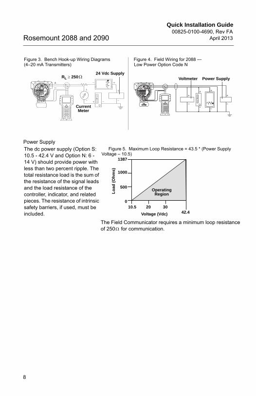
Power Supply
Figure 3. Bench Hook-up Wiring Diagrams (4–20 mA Transmitters)
Figure 4. Field Wiring for 2088 —Low Power Option Code N
The dc power supply (Option S: 10.5 - 42.4 V and Option N: 6 - 14 V) should provide power with less than two percent ripple. The total resistance load is the sum of the resistance of the signal leads and the load resistance of the controller, indicator, and related pieces. The resistance of intrinsic safety barriers, if used, must be included.
Figure 5. Maximum Loop Resistance = 43.5 * (Power Supply Voltage – 10.5)
CurrentMeter
24 Vdc SupplyRL 250 Power SupplyVoltmeter
Voltage (Vdc)
Lo
ad (
Oh
ms)
OperatingRegion
1387
1000
500
010.5 20 30
42.4
The Field Communicator requires a minimum loop resistanceof 250 for communication.
8
Quick Installation Guide00825-0100-4690, Rev FAApril 2013 Rosemount 2088 and 2090
4690 Rev FA.fm Page 9 Monday, April 15, 2013 8:11 AM
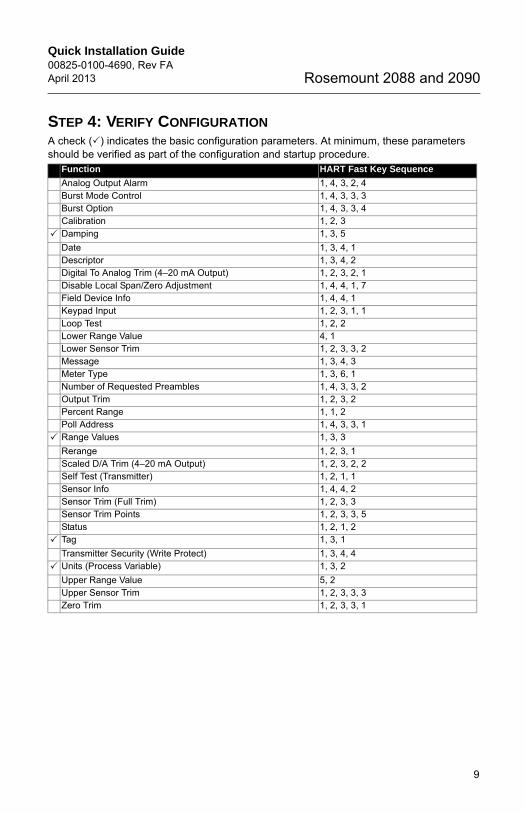
STEP 4: VERIFY CONFIGURATIONA check () indicates the basic configuration parameters. At minimum, these parameters should be verified as part of the configuration and startup procedure.
Function HART Fast Key Sequence
Analog Output Alarm 1, 4, 3, 2, 4Burst Mode Control 1, 4, 3, 3, 3 Burst Option 1, 4, 3, 3, 4 Calibration 1, 2, 3
Damping 1, 3, 5
Date 1, 3, 4, 1Descriptor 1, 3, 4, 2Digital To Analog Trim (4–20 mA Output) 1, 2, 3, 2, 1Disable Local Span/Zero Adjustment 1, 4, 4, 1, 7Field Device Info 1, 4, 4, 1Keypad Input 1, 2, 3, 1, 1Loop Test 1, 2, 2Lower Range Value 4, 1Lower Sensor Trim 1, 2, 3, 3, 2Message 1, 3, 4, 3Meter Type 1, 3, 6, 1Number of Requested Preambles 1, 4, 3, 3, 2Output Trim 1, 2, 3, 2 Percent Range 1, 1, 2Poll Address 1, 4, 3, 3, 1
Range Values 1, 3, 3
Rerange 1, 2, 3, 1Scaled D/A Trim (4–20 mA Output) 1, 2, 3, 2, 2Self Test (Transmitter) 1, 2, 1, 1Sensor Info 1, 4, 4, 2Sensor Trim (Full Trim) 1, 2, 3, 3Sensor Trim Points 1, 2, 3, 3, 5Status 1, 2, 1, 2
Tag 1, 3, 1
Transmitter Security (Write Protect) 1, 3, 4, 4
Units (Process Variable) 1, 3, 2
Upper Range Value 5, 2Upper Sensor Trim 1, 2, 3, 3, 3Zero Trim 1, 2, 3, 3, 1
9

Quick Installation Guide00825-0100-4690, Rev FA
April 2013Rosemount 2088 and 2090
4690 Rev FA.fm Page 10 Monday, April 15, 2013 8:11 AM
STEP 5: TRIM THE TRANSMITTER
NOTETransmitters are shipped fully calibrated per request or by the factory default of full scale (span = upper range limit).
Zero Trim A zero trim is a single-point adjustment used for compensating mounting position effects. If zero offset is less than 3% of true zero, follow the “Using the Field Communicator” instructions below. If zero offset is greater than 3% of true zero, follow the “Using the Transmitter Zero Adjustment Button” instructions below to rerange.
Using the Field Communicator
Using the Transmitter Zero Adjustment Button
Fast Keys Steps
1, 2, 3, 3, 1 1. Vent the transmitter and connect Field Communicator.2. At the menu, input the HART Fast Key sequence.3. Follow the commands to perform a zero trim.
1. Loosen the certifications label screw and rotate the label to expose the zero adjustment button.
2. Apply the desired pressure for the 4 mA output.
3. Set the 4 mA point by pressing the zero button for 2 seconds. Verify that the output is 4 mA. The optional LCD will display ZERO PASS.
Zero Adjustment Button
10
Quick Installation Guide00825-0100-4690, Rev FAApril 2013 Rosemount 2088 and 2090
4690 Rev FA.fm Page 11 Monday, April 15, 2013 8:11 AM
SAFETY INSTRUMENTED SYSTEMSThe following section applies to 2088 transmitters used in SIS applications.
NOTETransmitter output is not safety-rated during the following: configuration changes, multidrop, loop test. Alternative means should be used to ensure process safety during transmitter configuration and maintenance activities.
InstallationNo special installation is required in addition to the standard installation practices outlined in this document. Always ensure a proper seal by installing the electronics housing cover(s) so that metal contacts metal.
The loop must be designed so the terminal voltage does not drop below 10.5 Vdc when the transmitter output is 22.5 mA.
Position the security switch to the “ON” position to prevent accidental or deliberate change of configuration data during normal operation.
ConfigurationUse any HART-compliant master to communicate with and verify configuration of the 2088.
User-selected damping will affect the transmitters ability to respond to changes in the applied process. The damping value + response time must not exceed the loop requirements.
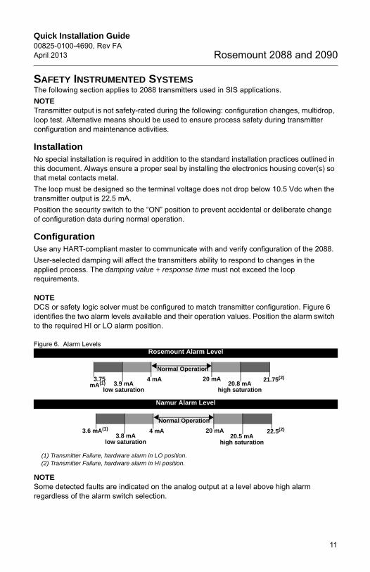
NOTEDCS or safety logic solver must be configured to match transmitter configuration. Figure 6 identifies the two alarm levels available and their operation values. Position the alarm switch to the required HI or LO alarm position.
Figure 6. Alarm Levels
NOTESome detected faults are indicated on the analog output at a level above high alarm regardless of the alarm switch selection.
Rosemount Alarm Level
Namur Alarm Level
(1) Transmitter Failure, hardware alarm in LO position. (2) Transmitter Failure, hardware alarm in HI position.
Normal Operation
4 mA 20 mA20.8 mA
high saturation
21.75(2)3.9 mA
low saturation
3.75mA(1)
Normal Operation
4 mA 20 mA20.5 mA
high saturation
22.5(2)
3.8 mAlow saturation
3.6 mA(1)
11
Quick Installation Guide00825-0100-4690, Rev FA
April 2013Rosemount 2088 and 2090
4690 Rev FA.fm Page 12 Monday, April 15, 2013 8:11 AM
Operation and MaintenanceProof Test and Inspection
The following proof tests are recommended. Proof test results and corrective actions taken must be documented at www.emersonprocess.com/rosemount/safety/certtechdocumentation.htm in the event that an error is found in the safety functionality.
Use "Table 1: Input Parameters" to perform a Loop Test, Analog Output Trim, or Sensor Trim. See the 2088 reference manual (00809-0100-4690) for additional information.
Proof Test
This proof test will detect 92% of DU failures not detected by the 2088 automatic diagnostics.
1. Bypass the safety PLC and take appropriate action to avoid a false trip. 2. Send a HART command to the transmitter to go to the high alarm current output and
verify that the analog current reaches that value (1).3. Send a HART command to the transmitter to go to the low alarm current output and
verify that the analog current reaches that value (2).4. Perform a minimum two-point sensor calibration check using the 4-20 mA range points
as the calibration points and verify that the mA output corresponds to the pressure input value(3).
5. Restore loop to full operation.6. Remove the bypass and otherwise restore normal operation.
Product RepairAll failures detected by the transmitter diagnostics or by the proof-test must be reported. Feedback can be submitted electronically at www.emersonprocess.com/rosemount/safety/certtechdocumentation.htm.
The 2088 is repairable by major component replacement. Follow the instructions in the 2088 reference manual (document number 00809-0100-4690) for additional information.
Reference
Specifications
The 2088 must be operated in accordance to the functional and performance specifications provided in the 2088 reference manual.
Failure Rate Data
The FMEDA report includes failure rates. This report is available at www.emersonprocess.com/rosemount.
(1) This tests for compliance voltage problems such as a low loop power supply voltage or increased wiring resistance. This also tests for other possible failures.
(2) This tests for possible quiescent current related failures.(3) If the two-point calibration is performed with electrical instrumentation, this proof test will not detect any
failures of the sensor.
12
Quick Installation Guide00825-0100-4690, Rev FAApril 2013 Rosemount 2088 and 2090
4690 Rev FA.fm Page 13 Monday, April 15, 2013 8:11 AM
2088 Safety Failure Values
Safety accuracy: 2.0%(1)
Safety response time: 1.5 sec
Product Life
50 years – based on worst case component wear-out mechanisms – not based on wear-out process wetted materials.
(1) A 2% variation of the transmitter mA output is allowed before a safety trip. Trip values in the DCS or safetylogic solver should be derated by 2%.
13

Quick Installation Guide00825-0100-4690, Rev FA
April 2013Rosemount 2088 and 2090
4690 Rev FA.fm Page 14 Monday, April 15, 2013 8:11 AM
PRODUCT CERTIFICATIONS
Approved Manufacturing LocationsRosemount Inc. - Chanhassen, Minnesota, USA
Emerson Process Management GmbH & Co. - Wessling, Germany
Emerson Process Management Asia Pacific Private Limited - Singapore
Beijing Rosemount Far East Instrument Co., Limited - Beijing, China
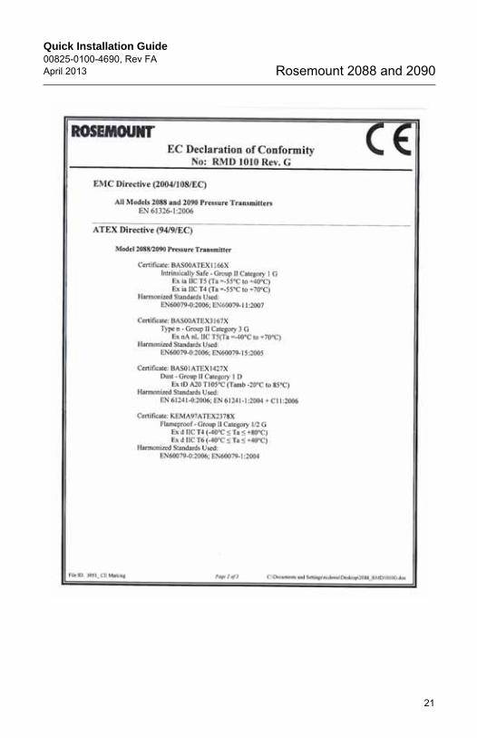
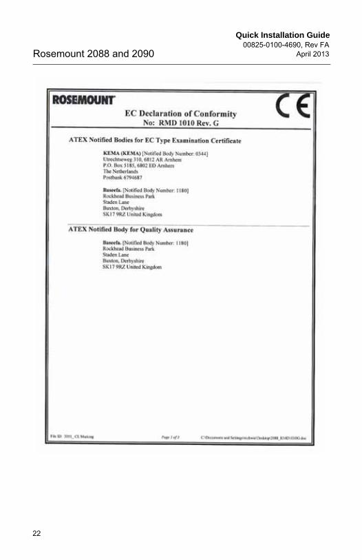
European Directive InformationThe EC declaration of conformity can be found on page 14. The most recent revision can be found at www.rosemount.com.
ATEX Directive (94/9/EC)Emerson Process Management complies with the ATEX Directive.
European Pressure Equipment Directive (PED) (97/23/EC) Model 2088/2090 Pressure Transmitters
- Sound Engineering Practice
Electro Magnetic Compatibility (EMC) (2004/108/EC)All Model 2088/2090 Pressure Transmitter: EN 61326-1:2006
Hazardous Locations CertificationsNorth American Certifications
Factory Mutual (FM)E5 Explosion-proof and Dust Ignition Proof
Certificate No.: 1V2A8.AE Applicable Standards: FM Class 3600 - 1998, FM Class 3615 - 1989, FM Class 3810 - 1989Markings: Explosion-proof for Class I, Division 1, Groups B, C, and D. Dust Ignition-Proof for Class II/III, Division 1, Groups E, F and G.Temperature Code: T5 (Ta = -40 °C to + 85 °C) Factory Sealed, Enclosure Type 4X.For input parameters see control drawing 02088-1018
I5 Intrinsically Safe and Non-IncendiveCertificate No.: 0V9A7.AXApplicable Standards: FM Class 3600 - 1998, FM Class 3610 - 2010, FM Class 3811 - 2004, FM Class 3810 - 1989.Markings: Intrinsically safe for use in Class I, Division 1, Groups A, B, C, D; Class II, Division 1, Groups E, F, and G; and Class III, Division 1 Temperature Code: T4 (Ta = 70 °C) in accordance with Rosemount drawing 02088-1018. Non-incendive for Class I, Division 2, Groups A, B, C, and D. Temperature Code: T4 (Ta = 85 °C), Enclosure Type 4X.For input parameters see control drawing 02088-1018.
14

Quick Installation Guide00825-0100-4690, Rev FAApril 2013 Rosemount 2088 and 2090
4690 Rev FA.fm Page 15 Monday, April 15, 2013 8:11 AM
15
Canadian Standards Association (CSA)
All CSA hazardous approved transmitters are certified per ANSI/ISA 12.27.01-2003.C6 Explosion-Proof, Intrinsically Safe, Dust Ignition-Proof and Class I Division 2
Applicable Standards: CAN/CSA Std. C22.2 No. 0-M91, CSA Std. C22.2 No. 25 - 1966, CSA Std. C22.2 No. 30 - M1986, CAN/CSA Std. C22.2 No. 94 - M91, CSA Std. C22.2 No. 142 - M1987, CAN/CSA Std. C22.2 No. 157-92, CSA Std. C22.2 No. 213 - M1987, ANSI/ISA 12.27.01-2003.Markings: Explosion-proof for Class I, Division 1, Groups B, C, and D. Dust-Ignition-Proof for Class II, Division 1, Groups E, F, G, Class III. Suitable for Class I, Division 2, Groups A, B, C, and D.Intrinsically Safe for Class I, Division 1, Groups A, B, C, and D. Temperature Code: T3C. Enclosure Type 4X. Factory sealed. Single Seal. See control drawing 02088-1024.
European Certifications
ED ATEX FlameproofCertification No.: KEMA97ATEX2378X Applicable Standards: EN60079-0:2006, EN60079-1:2007, EN60079-26:2007 Markings: II 1/2 G Ex d IIC T6 (-40 °C Tamb 40 °C); T4 (-40 °C Tamb 80 °C)
1180Vmax = 36 (with Output Code S) Vmax = 14 (with Output Code N)
Special Conditions for Safe Use (x):1.The cable and conduit entry devices shall be of a certified flameproof type Ex d, suitable for the conditions of use and correctly installed.2.With the use of conduit entries a sealing device shall be provided immediately on the entrance thereto.3.Unused apertures shall be closed with suitable Ex d certified blanking elements.4.Suitable heat-resisting cables shall be used when the ambient temperature at the cable or conduit entries exceed 65 °C.5.This device contains a thin wall diaphragm. Installation, maintenance, and use shall take into account the environmental conditions to which the diaphragm will be subjected. The manufacturer's instructions for installation and maintenance shall be followed in detail to assure safety during its expected lifetime.6.For information on the dimensions of the flameproof joints the manufacturer shall be contacted.
I1 ATEX Intrinsic Safety Certificate No.: BAS00ATEX1166XApplicable Standards: EN60079-0:2012, EN60079-11: 2012 Markings: II 1 G Ex ia IIC T5 Ga (–55 °C ≤ Tamb ≤ +40 °C)Ex ia IIC T4 Ga (–55 °C ≤ Tamb ≤ +70 °C)
1180
Quick Installation Guide00825-0100-4690, Rev FA
April 2013Rosemount 2088 and 2090
4690 Rev FA.fm Page 16 Monday, April 15, 2013 8:11 AM
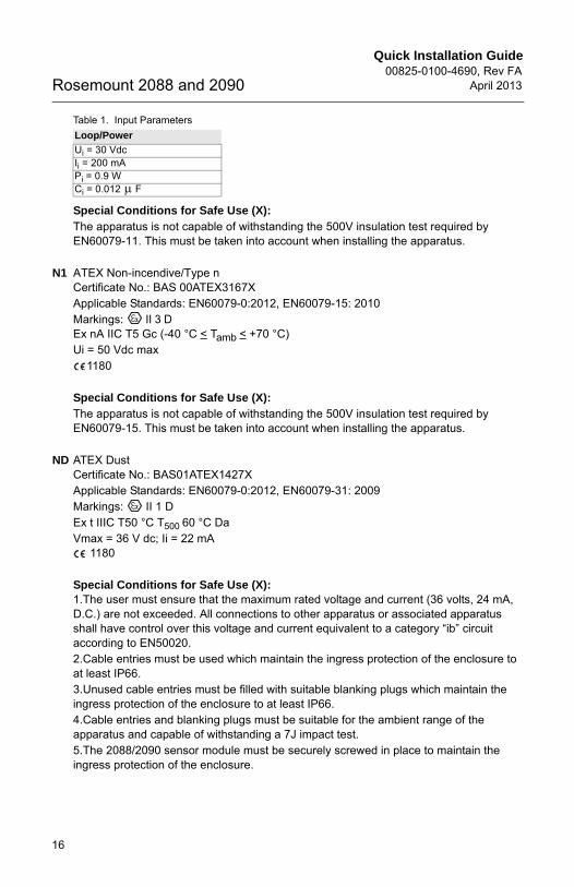
Table 1. Input Parameters
Special Conditions for Safe Use (X): The apparatus is not capable of withstanding the 500V insulation test required by EN60079-11. This must be taken into account when installing the apparatus.
N1 ATEX Non-incendive/Type n Certificate No.: BAS 00ATEX3167XApplicable Standards: EN60079-0:2012, EN60079-15: 2010Markings: II 3 DEx nA IIC T5 Gc (-40 °C < Tamb < +70 °C)Ui = 50 Vdc max
1180
Special Conditions for Safe Use (X):The apparatus is not capable of withstanding the 500V insulation test required by EN60079-15. This must be taken into account when installing the apparatus.
ND ATEX DustCertificate No.: BAS01ATEX1427XApplicable Standards: EN60079-0:2012, EN60079-31: 2009Markings: II 1 D Ex t IIIC T50 °C T500 60 °C Da Vmax = 36 V dc; Ii = 22 mA
1180
Special Conditions for Safe Use (X): 1.The user must ensure that the maximum rated voltage and current (36 volts, 24 mA, D.C.) are not exceeded. All connections to other apparatus or associated apparatus shall have control over this voltage and current equivalent to a category “ib” circuit according to EN50020.2.Cable entries must be used which maintain the ingress protection of the enclosure to at least IP66.3.Unused cable entries must be filled with suitable blanking plugs which maintain the ingress protection of the enclosure to at least IP66.4.Cable entries and blanking plugs must be suitable for the ambient range of the apparatus and capable of withstanding a 7J impact test.5.The 2088/2090 sensor module must be securely screwed in place to maintain the ingress protection of the enclosure.
Loop/Power
Ui = 30 VdcIi = 200 mAPi = 0.9 WCi = 0.012 F
16

Quick Installation Guide00825-0100-4690, Rev FAApril 2013 Rosemount 2088 and 2090
4690 Rev FA.fm Page 17 Monday, April 15, 2013 8:11 AM
IECEx Certifications
E7 IECEx Flameproof Certification No.: IECEx KEM 06.0021XApplicable Standards: IEC60079-0:2004, IEC60079-1:2003, IEC60079-26:2004 Markings: Ex d IIC T4 (-20 °C Tamb °C)Ex d IIC T6 (-20 °C Tamb °C)
I7 IECEx Intrinsic Safety Certificate No.: IECEx BAS 12.0071XApplicable Standards: IEC60079-0:2011, IEC60079-11: 2011 Markings: Ex ia IIC T5 Ga (-55 °C Tamb 40 °C)Ex ia IIC T4 Ga (–55 °C Tamb +70 °C)
Table 2. Input Parameters
Special Conditions for Safe Use (X): The equipment is not capable of withstanding the 500V insulation test required by EN60079-11. This must be taken into account when installing the equipment.
N7 IECEx Non-incendive/Type n Certificate No.: IECEx BAS 12.0072XApplicable Standards: EN60079-0:202012, EN60079-15: 2010Markings: Ex nA IIC T5 Gc (-40 °C Tamb +70 °C)Ui = 50 Vdc max
Input Parameters
Special Conditions for Safe Use (X): The equipment is not capable of withstanding the 500V insulation test required by EN60079-11. This must be taken into account when installing the equipment.
NK IECEx DustCertificate No.: IECEx BAS12.0073XApplicable Standards: IEC60079-0:2011, IEC60079-31: 2008Markings: Ex t IIIC T50 °C T500 60 °C Da Vmax = 36 Vdc; Ii = 24 mA
Loop/Power
Ui = 30 VdcIi = 200 mAPi = 0.9 WCi = 0.012 F
Loop/Power
Ui = 30 VdcIi = 200 mAPi = 0.9 WCi = 0.012 F
17

Quick Installation Guide00825-0100-4690, Rev FA
April 2013Rosemount 2088 and 2090
4690 Rev FA.fm Page 18 Monday, April 15, 2013 8:11 AM
Special Conditions for Safe Use (X): 1.The device contains a thin wall diaphragm. Installation, maintenance, and use shall take into account the environmental conditions to which the diaphragm will be subjected. The manufacturer's instructions for installation and maintenance shall be followed in detail to assure safety during its expected lifetime.2.Cable entries must be used which maintain the ingress protection of the enclosure to at least IP66.3.Unused cable entries must be used which maintain the ingress protection of the enclosure to at least IP66.4.Cable entries and blanking plugs must be suitable for the ambient range of the apparatus and capable of withstanding a 7J impact.5.The 2088/2090 sensor module must be securely screwed in place to maintain the ingress protection of the enclosure.
Japanese Certifications
E4 TIIS Flame-ProofEx d IIC T6
Brazil Certifications
I2 INMETRO Intrinsic SafetyCertificate No.: CEPEL 97.0063X; Markings: Ex ia IIC T5/T4 Ga/Gb T5 (-20 °C Tamb +40 °C); T4 (-20 °C Tamb +60 °C)
E2 INMETRO Flameproof (2088 Series only)Certificate No.: CEPEL 97.0076Markings: Ex d IIC T6/T5 Gb T6 (-20 °C Tamb +40 °C); T5 (-20 °C Tamb +60 °C)
China Certifications
I3 China Intrinsic SafetyCertificate No.: GYJ111063X (2088 Series); GYJ111065X (2090 Series) Applicable Standards: GB3836.1-2000, GB3836.4-2000Markings: Ex ia IIC T4/T5 T4 (-55 °C Tamb +70 °C); T5 (-55 °C Tamb +40 °C)
Table 3. Input Parameters
Refer to Appendix B of the 2088/2090 Reference Manual (document number 00809-0100-4108) for Special Conditions for Safe Use.
Certificate Description
TC15874 2088 with Alloy C-276 wetted parts (with display)TC15873 2088 with SST wetted parts (with display)TC15872 2088 with Alloy C-276 wetted parts (no display)TC15871 2088 with SST wetted parts (no display)
Loop/Power
Ui = 30 VdcIi = 200 mAPi = 0.9 WCi = 0.012 F
18

Quick Installation Guide00825-0100-4690, Rev FAApril 2013 Rosemount 2088 and 2090
4690 Rev FA.fm Page 19 Monday, April 15, 2013 8:11 AM
E3 China FlameproofCertificate No.: GYJ111062 (2088 Series); GYJ111064 (2090 Series)Applicable Standards: GB3836.1-2000, GB3836.2-2000Markings: Ex d IIC T4/T6 T4 (-20 °C Tamb +40 °C); T6 (-20 °C Tamb +80 °C)
Refer to Appendix B of the 2088/2090 Reference Manual (document number00809-0100-4108) for Special Conditions for Safe Use.
N3 China Type n Non-SparkingCertificate No.: GYJ101126X (2088 Series)Applicable Standards: GB3836.1-2000, GB3836.8-2000Markings: Ex nA nL IIC T5 (-40°C ≤ Tamb ≤ +70°C)
Refer to Appendix B of the 2088/2090 Reference Manual (document number00809-0100-4108) for Special Conditions for Safe Use.
Combinations of Certifications
Stainless steel certification tag is provided when optional approval is specified. Once a device labeled with multiple approval types is installed, it should not be reinstalled using any other approval types. Permanently mark the approval label to distinguish it from unused approval types.
K1 I1, N1, ED, and ND combination
K5 E5 and I5 combination
K6 C6, I1 and ED combination
K7 E7, I7, N7, and NK combination
KB K5, and C6 combination
KH K5, ED, and I1 combination
19

Quick Installation Guide00825-0100-4690, Rev FA
April 2013Rosemount 2088 and 2090
4690 Rev FA.fm Page 20 Monday, April 15, 2013 8:11 AM
20
Quick Installation Guide00825-0100-4690, Rev FAApril 2013 Rosemount 2088 and 2090
4690 Rev FA.fm Page 21 Monday, April 15, 2013 8:11 AM
21
Quick Installation Guide00825-0100-4690, Rev FA
April 2013Rosemount 2088 and 2090
4690 Rev FA.fm Page 22 Monday, April 15, 2013 8:11 AM
22
Related Documents