QUICK INSTALLATION GUIDE HYBRID INVERTER 3-6-ZSS-HP Rev. 1.0 – 23/05/2022

Welcome message from author
This document is posted to help you gain knowledge. Please leave a comment to let me know what you think about it! Share it to your friends and learn new things together.
Transcript

QUICK INSTALLATION GUIDE HYBRID INVERTER 3-6-ZSS-HP
Rev. 1.0 – 23/05/2022
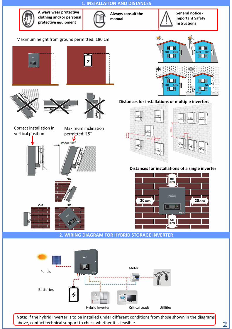
Note: If the hybrid inverter is to be installed under different conditions from those shown in the diagrams above, contact technical support to check whether it is feasible.
1. INSTALLATION
Maximum inclination permitted: 15°
Correct installation in vertical position
Maximum height from ground permitted: 180 cm
2. WIRING DIAGRAM FOR HYBRID STORAGE INVERTER
1. INSTALLATION AND DISTANCES
20 20
Distances for installations of a single inverter
Distances for installations of multiple inverters
Always wear protective clothing and/or personal protective equipment
Always consult the manual
General notice -Important Safety Instructions
Panels
Hybrid Inverter
Meter
Critical Loads Utilities
Batteries

1
5
6
7
2 3 4
98
10
1112
13
1. Menu/Back 2. Up3. Down4. Enter/Forward5. Discharge status6. Charge status7. Alarm status
8. System status9. PV production10. Grid power11. Home
consumption12. Battery power13. Date and time14. Wi-Fi signal
143. LIGHTS AND BUTTONS
Main menu
1. System settings
2. Advanced settings
3. Event list
4. System Info
5. Software Update
6. Energy statistics
From the main menu, press “Menu/Back” to enter the main menu.The main menu contains five different sections:
4. MAIN MENU
1. System settings1. Language Setting
2. Time3. Safety Param.
4. Energy Storage Mode5. Autotest
6. PV input mode
7. EPS Mode
8. Select.Commun.Address
2. Advanced settings1. Battery parameters
2. Anti Reflux3. IV Curve Scan
4. Logic interface
5. Factory Reset
6. Parallel setting
7. Rest Buetooth
8. CT Calibration
9. Battery Active
10. Set Electricity Meter
3. Event list1. List of current events
2. List of historical events
4. System Info1. Inverter Info
2. Battery Info3. Safety parameters
6.Energy StatisticsToday Week Month Year Life CyclePV prod. PV prod. PV prod. PV prod. PV prod.
AutoCon AutoCon AutoCon AutoCon AutoCon
Export Export Export Export Export
Consumption Consumption Consumption Consumption Consumption
AutoCon AutoCon AutoCon AutoCon AutoCon
Amount Amount Amount Amount Amount
5. SW UpdateStart Update ...
PWD: 0715
PWD: 0715
Status of the HYD-ES inverter
On Grid
Green light
Off-Grid
Green light
Alarm
Red lightOn-grid On
Standby (On-Grid) IntermittentOff-Grid On
Standby (Off-Grid) IntermittentAlarm On
Charge
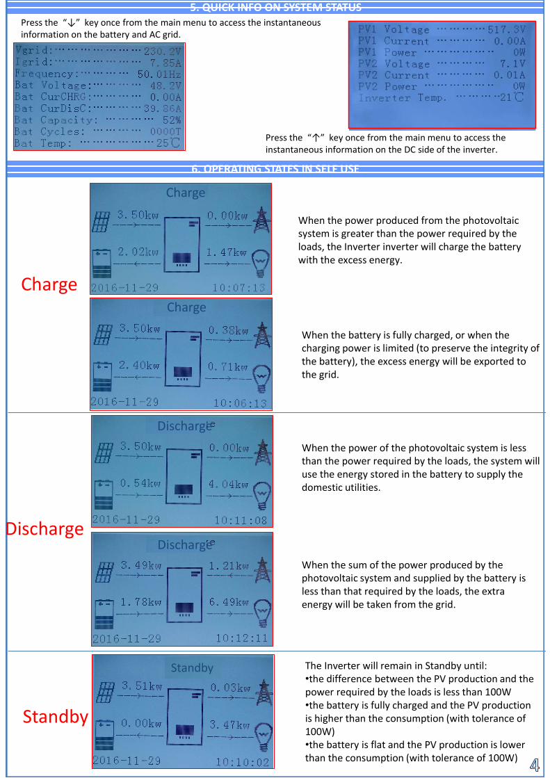
The Inverter will remain in Standby until: •the difference between the PV production and the power required by the loads is less than 100W•the battery is fully charged and the PV production is higher than the consumption (with tolerance of 100W)•the battery is flat and the PV production is lower than the consumption (with tolerance of 100W)
Press the “↓” key once from the main menu to access the instantaneous information on the battery and AC grid.
Press the “↑” key once from the main menu to access the instantaneous information on the DC side of the inverter.
6. OPERATING STATES IN SELF USE
5. QUICK INFO ON SYSTEM STATUS
When the power produced from the photovoltaic system is greater than the power required by the loads, the Inverter inverter will charge the battery with the excess energy.
When the battery is fully charged, or when the charging power is limited (to preserve the integrity of the battery), the excess energy will be exported to the grid.
Charge
When the power of the photovoltaic system is less than the power required by the loads, the system will use the energy stored in the battery to supply the domestic utilities.
Discharge
When the sum of the power produced by the photovoltaic system and supplied by the battery is less than that required by the loads, the extra energy will be taken from the grid.
Standby
StandbyStandby
Charge
Charge
Discharge
Discharge

3.1 Connessione BatteriaIf the system has to be switched off, make sure to disconnect the AC voltage first by opening the dedicated switch.NEVER turn off the batteries before disconnecting the AC voltage, therefore with the storage system connected to the AC grid.
Note: Maximum DoDProgrammable 80%
8.1 SINGLE PYLONTECH BATTERY
7. BATTERY CONNECTION
3.3 Connessioni alla Rete
InverterPIN
Batterycommunication Note
1 CAN H (blue wire)Communication betweenbattery BMS and Inverter
2CAN L white/blue
wire )
Inverter COM connector
Fase 2 Fase 3
PowerConnections
Communication connections
In case of a single battery, two power cables (positive and negative) and a communication cable shall be connected. This connection is shown in the figures below:
Note: The communication cable is located inside the kit in the inverter box.
Note: The DIP switch positions must be set according to the factory settings
The communication cable shall be connected to the battery's CAN port
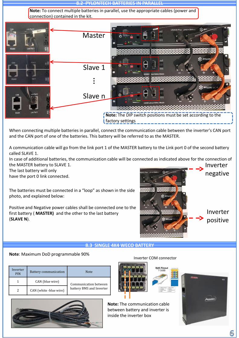
When connecting multiple batteries in parallel, connect the communication cable between the inverter's CAN port and the CAN port of one of the batteries. This battery will be referred to as the MASTER.
A communication cable will go from the link port 1 of the MASTER battery to the Link port 0 of the second battery called SLAVE 1.In case of additional batteries, the communication cable will be connected as indicated above for the connection of the MASTER battery to SLAVE 1.The last battery will only have the port 0 link connected.
8.2 PYLONTECH BATTERIES IN PARALLEL
8.3 SINGLE 4K4 WECO BATTERY
Master
Slave 1
Slave n
…
The batteries must be connected in a “loop” as shown in the side photo, and explained below:
Positive and Negative power cables shall be connected one to the first battery ( MASTER) and the other to the last battery(SLAVE N).
Inverter negative
Inverter positive
3.1 Connessione Batteria
Note: To connect multiple batteries in parallel, use the appropriate cables (power and connection) contained in the kit.
Note: The DIP switch positions must be set according to the factory settings
Note: The communication cablebetween battery and inverter isinside the inverter box
Note: Maximum DoD programmable 90%
InverterPIN Battery communication Note
1 CAN (blue wire)Communication betweenbattery BMS and Inverter
2 CAN (white -blue wire)
Inverter COM connector
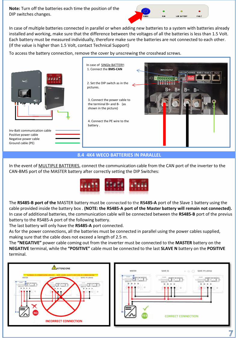
In case of SINGle BATTERY:1. Connect the BMS-CAN
2. Set the DIP switch as in thepictures.
3. Connect the power cable tothe terminal B+ and B- (asshown in the picture)
4. Connect the PE wire to thebattery .
In case of multiple batteries connected in parallel or when adding new batteries to a system with batteries already installed and working, make sure that the difference between the voltages of all the batteries is less than 1.5 Volt.Each battery must be measured individually, therefore make sure the batteries are not connected to each other. (If the value is higher than 1.5 Volt, contact Technical Support)
Note: Turn off the batteries each time the position of the DIP switches changes.
To access the battery connection, remove the cover by unscrewing the crosshead screws.
In the event of MULTIPLE BATTERIES, connect the communication cable from the CAN port of the inverter to the CAN-BMS port of the MASTER battery after correctly setting the DIP Switches:
The RS485-B port of the MASTER battery must be connected to the RS485-A port of the Slave 1 battery using the cable provided inside the battery box . (NOTE: the RS485-A port of the Master battery will remain not connected).In case of additional batteries, the communication cable will be connected between the RS485-B port of the previusbattery to the RS485-A port of the following battery.The last battery will only have the RS485-A port connected.As for the power connections, all the batteries must be connected in parallel using the power cables supplied, making sure that the cable does not exceed a length of 2.5 m.The “NEGATIVE” power cable coming out from the inverter must be connected to the MASTER battery on the NEGATIVE terminal, while the “POSITIVE” cable must be connected to the last SLAVE N battery on the POSITIVEterminal.
8.4 4K4 WECO BATTERIES IN PARALLEL
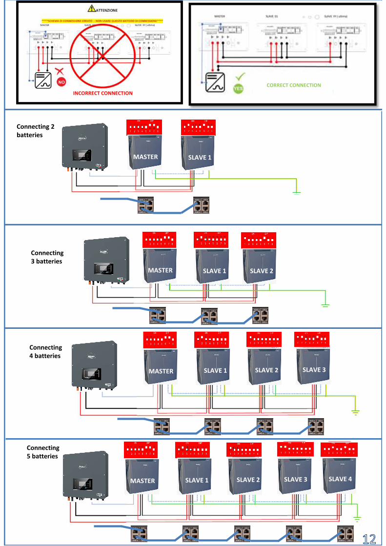
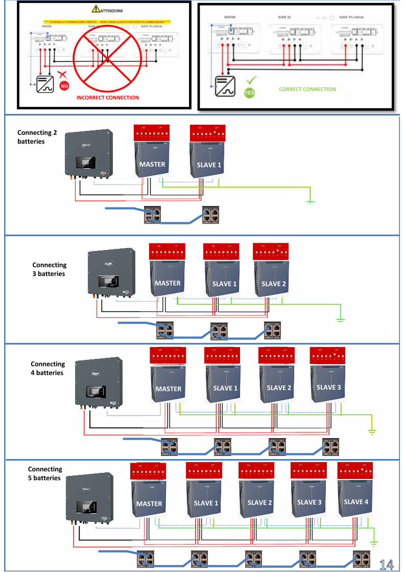
INCORRECT CONNECTIONCORRECT CONNECTION
Inv-Batt communication cablePositive power cableNegative power cableGround cable (PE)
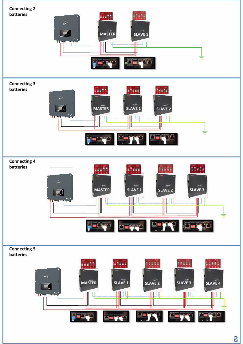
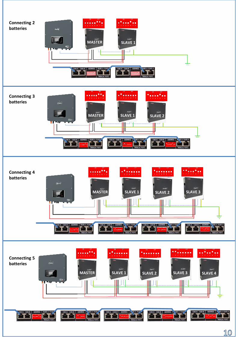
MASTER SLAVE 1
MASTER SLAVE 1 SLAVE 2
MASTER SLAVE 1 SLAVE 2 SLAVE 3
MASTER SLAVE 1 SLAVE 2 SLAVE 3 SLAVE 4
Connecting 5 batteries
Connecting 4 batteries
Connecting 3 batteries
Connecting 2 batteries

8.5 BATTERIA 4K4PRO WECO SINGOLA
Note: Maximum DoD programmable 90%
In case of multiple batteries connected in parallel or when adding new batteries to a system with batteries already installed and operating, make sure that the difference between the voltages of all the batteries is less than 1.5 volts. Each battery must be measured individually, therefore make sure the batteries are not connected to each other. (If the value is higher than 1.5 volts, contact Technical Support).
Note: The communication cables are in the kit that is contained in the WeCobattery box
In caso di SINGOLA BATTERIA:1. Connettere l‘ingresso CAN-A
2. Impostare i DIP Switch comein figura
3. Le connessioni di potenzadovranno avvenire agganciandogli appositi connettori B+ e B-nell‘ingresso corrispettivo (comeda figura)
4. Collegare il cavo di terra alla batteria tramite il foro filettato
Cavo comunicazione Inv-BattCavo potenza positivoCavo potenza negativoCavo di Terra (PE)
In the event of MULTIPLE BATTERIES, connect the communication cable from the CAN port of the inverter to the CAN-BMS port of the MASTER battery after correctly setting the DIP Switches:
8.6 WECO 4K4PRO BATTERIES IN PARALLEL
The RS485-B port of the MASTER battery must be connected to the RS485-A port of the Slave 1 battery using the cable provided inside the battery box . (NOTE: the RS485-A port ofthe Master battery will remain not connected).In case of additional batteries, the communication cable will be connected between the RS485-B port of the previous battery to the RS485-A port of the following battery.The last battery will only have the RS485-A port connected.As for the power connections, all the batteries must be connected in parallel using the power cables supplied, making sure that the cable does not exceed a length of 2.5 m.The “NEGATIVE” power cable coming out from the inverter must be connected to the MASTER battery on the NEGATIVE terminal, while the “POSITIVE” cable must be connected to the last SLAVE N battery on the POSITIVEterminal.
COLLEGAMENTO NON CORRETTOCOLLEGAMENTO CORRETTO
Note: Turn off the batteries each time the position of the DIP switches is changed.presente nella scatola dell’inverter.
PIN Inverter
Comunicazione batteria Note
1CAN (white – orange
wire) Communicationbetween battery BMS
and Inverter2 CAN (orange wire)
Inverter COM connector
MASTER SLAVE 1
MASTER SLAVE 1 SLAVE 2
MASTER SLAVE 1 SLAVE 2 SLAVE 3
MASTER SLAVE 1 SLAVE 2 SLAVE 3 SLAVE 4
Connecting 5 batteries
Connecting 4 batteries
Connecting 3 batteries
Connecting 2 batteries

8.7 SINGLE 5k3 WECO BATTERY
Note: Maximum DoD programmable 90%Note: The communication and power cables must be ordered separatelyNote: Turn off the batteries each time of the DIP switches is position changed.
In case of multiple batteries connected in parallel or when adding new batteries to a system with batteries already installed and operating, make sure that the difference between the voltages of all the batteries is less than 1.5 volts. Each battery must be measured individually, therefore make sure the batteries are not connected to each other. (If the value is higher than 1.5 volts, contact Technical Support). To access the battery connection, remove the cover of the LV section located on the left hand side by unscrewing the crosshead screws. See the figure to identify the LV section
8.7 SINGLE 5k3 WECO BATTERY
Inv-Batt communication cable Positive power cableNegative power cable Ground cable (PE)
Low voltage connector (LV)
High voltage connectors (HV)
Attention: When connecting 5k3 batteries to single-phase Inverter inverters, only the low voltage section must be used. To prevent damage to the batteries or inverter, do not use the high voltage section.
The RS485-B port of the MASTER battery must be connected to the RS485-A port of the Slave 1 battery using the cable provided inside the battery box . (NOTE: the RS485-A port of the Master battery will remain not connected).In case of additional batteries, the communication cable will be connected between the RS485-B port of the previous battery to the RS485-A port of the following battery. The last battery will only have the RS485-A port connected.As for the power connections, all the batteries must be connected in parallel using the power cables supplied, making sure that the cable does not exceed a length of 2.5 m.The “NEGATIVE” power cable coming out from the inverter must be connected to the MASTER battery on the NEGATIVE terminal, while the “POSITIVE” cable must be connected to the last SLAVE N battery on the POSITIVEterminal.
In case of a SINGLE BATTERY:1. Connect the CAN-A input2. Set the DIP switches as shown in the figure
3. Connect the power cables by attaching the appropriate B+ and B- connectors to the corresponding input (as shown in the figure).
4. Connect the ground cable to the battery through the threaded hole
8.8 WECO 5k3 BATTERIES IN PARALLELIn case of MULTIPLE BATTERIES, connect the communication cable from the CAN port of the inverter to the CAN- A port of the MASTER battery after defining the correct positioning of the DIP switches:
PIN Inverter
Comunicazione batteria Note
1CAN (white – orange
wire) Communicationbetween battery BMS
and Inverter2 CAN (orange wire)
Inverter COM connector
MASTER SLAVE 1
MASTER SLAVE 1 SLAVE 2
MASTER SLAVE 1 SLAVE 2 SLAVE 3
MASTER SLAVE 1 SLAVE 2 SLAVE 3 SLAVE 4
Connecting 3 batteries
Connecting 2 batteries
Connecting 4 batteries
Connecting 5 batteries
CORRECT CONNECTIONINCORRECT CONNECTION

8.7 SINGLE 5k3 WECO BATTERY
Note: Maximum DoD programmable 90%Note: The communication and power cables must be ordered separatelyNote: Turn off the batteries each time of the DIP switches is position changed.
In case of multiple batteries connected in parallel or when adding new batteries to a system with batteries already installed and operating, make sure that the difference between the voltages of all the batteries is less than 1.5 volts. Each battery must be measured individually, therefore make sure the batteries are not connected to each other. (If the value is higher than 1.5 volts, contact Technical Support). To access the battery connection, remove the cover of the LV section located on the left hand side by unscrewing the crosshead screws. See the figure to identify the LV section
8.9 SINGLE 5k3XP WECO BATTERY
Inv-Batt communication cable Positive power cableNegative power cable Ground cable (PE)
Low voltage connector (LV)
High voltage connectors (HV)
Attention: When connecting 5k3xp batteries to single-phase Inverter inverters, only the low voltage section must be used. To prevent damage to the batteries or inverter, do not use the high voltage section.
The RS485-B port of the MASTER battery must be connected to the RS485-A port of the Slave 1 battery using the cable provided inside the battery box . (NOTE: the RS485-A port of the Master battery will remain not connected).In case of additional batteries, the communication cable will be connected between the RS485-B port of the previous battery to the RS485-A port of the following battery. The last battery will only have the RS485-A port connected.As for the power connections, all the batteries must be connected in parallel using the power cables supplied, making sure that the cable does not exceed a length of 2.5 m.The “NEGATIVE” power cable coming out from the inverter must be connected to the MASTER battery on the NEGATIVE terminal, while the “POSITIVE” cable must be connected to the last SLAVE N battery on the POSITIVEterminal.
In case of a SINGLE BATTERY:1. Connect the CAN-A input2. Set the DIP switches as shown in the figure
3. Connect the power cables by attaching the appropriate B+ and B- connectors to the corresponding input (as shown in the figure).
4. Connect the ground cable to the battery through the threaded hole
8.10 WECO 5K3XP BATTERIES IN PARALLELIn case of MULTIPLE BATTERIES, connect the communication cable from the CAN port of the inverter to the CAN- A port of the MASTER battery after defining the correct positioning of the DIP switches:
PIN Inverter
Comunicazione batteria Note
1CAN (white – orange
wire) Communicationbetween battery BMS
and Inverter2 CAN (orange wire)
Inverter COM connector
MASTER SLAVE 1
MASTER SLAVE 1 SLAVE 2
MASTER SLAVE 1 SLAVE 2 SLAVE 3
MASTER SLAVE 1 SLAVE 2 SLAVE 3 SLAVE 4
Connecting 3 batteries
Connecting 2 batteries
Connecting 4 batteries
Connecting 5 batteries
CORRECT CONNECTIONINCORRECT CONNECTION
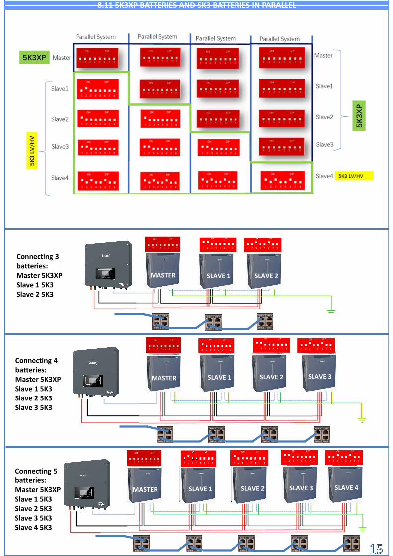
8.11 5K3XP BATTERIES AND 5K3 BATTERIES IN PARALLEL
Connecting 5 batteries:Master 5K3XPSlave 1 5K3Slave 2 5K3Slave 3 5K3Slave 4 5K3
MASTER SLAVE 1 SLAVE 2 SLAVE 3 SLAVE 4
Connecting 3 batteries:Master 5K3XPSlave 1 5K3Slave 2 5K3
Connecting 4 batteries:Master 5K3XPSlave 1 5K3Slave 2 5K3Slave 3 5K3
MASTER SLAVE 1 SLAVE 2
MASTER SLAVE 1 SLAVE 2 SLAVE 3
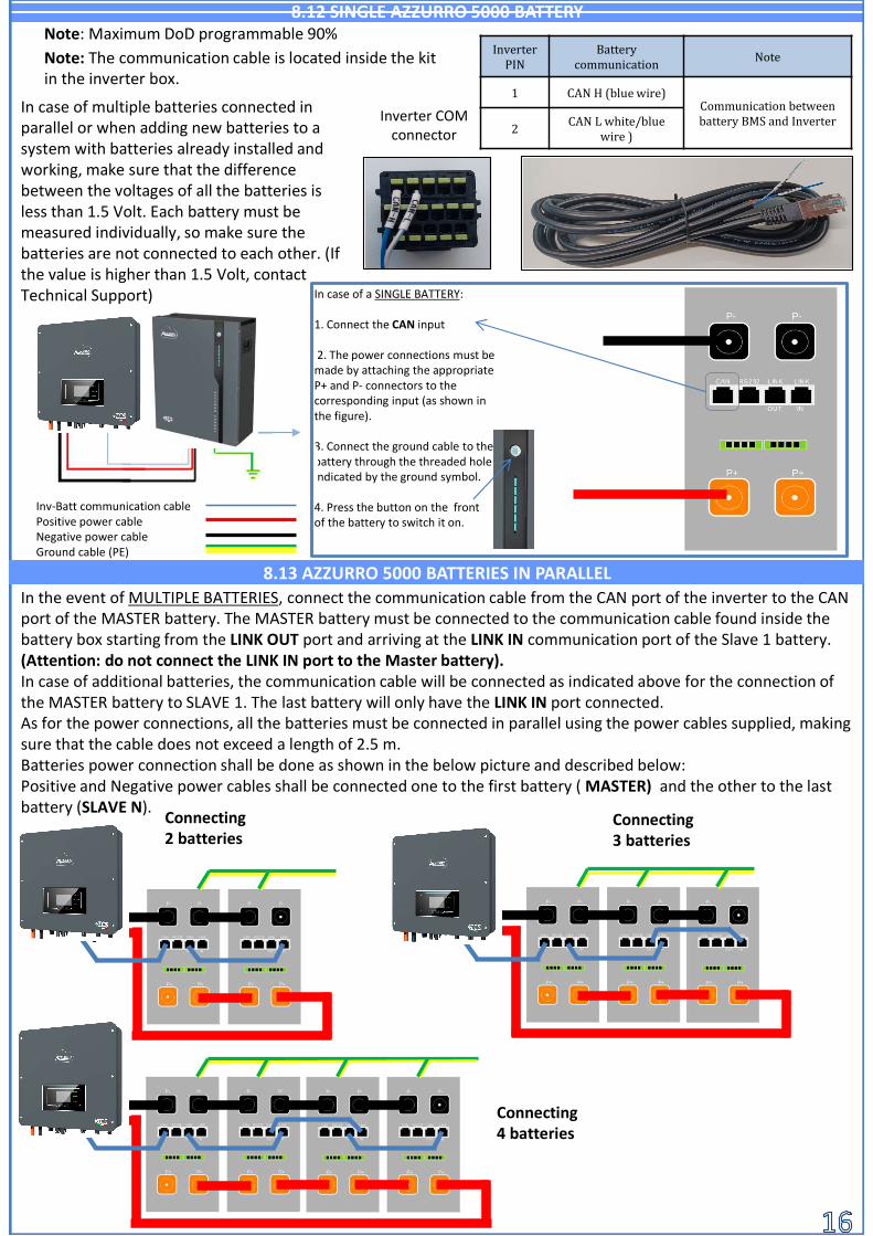
In case of a SINGLE BATTERY:
1. Connect the CAN input
2. The power connections must be made by attaching the appropriate P+ and P- connectors to the corresponding input (as shown in the figure).
3. Connect the ground cable to the battery through the threaded hole indicated by the ground symbol.
4. Press the button on the frontof the battery to switch it on.
8.12 SINGLE AZZURRO 5000 BATTERY
Note: The communication cable is located inside the kit in the inverter box.
Note: Maximum DoD programmable 90%
8.13 AZZURRO 5000 BATTERIES IN PARALLEL
InverterPIN
Batterycommunication
Note
1 CAN H (blue wire)Communication betweenbattery BMS and Inverter
2CAN L white/blue
wire )
Inverter COM connector
In case of multiple batteries connected in parallel or when adding new batteries to a system with batteries already installed and working, make sure that the difference between the voltages of all the batteries is less than 1.5 Volt. Each battery must be measured individually, so make sure the batteries are not connected to each other. (If the value is higher than 1.5 Volt, contact Technical Support)
In the event of MULTIPLE BATTERIES, connect the communication cable from the CAN port of the inverter to the CAN port of the MASTER battery. The MASTER battery must be connected to the communication cable found inside the battery box starting from the LINK OUT port and arriving at the LINK IN communication port of the Slave 1 battery. (Attention: do not connect the LINK IN port to the Master battery).In case of additional batteries, the communication cable will be connected as indicated above for the connection of the MASTER battery to SLAVE 1. The last battery will only have the LINK IN port connected.As for the power connections, all the batteries must be connected in parallel using the power cables supplied, making sure that the cable does not exceed a length of 2.5 m.Batteries power connection shall be done as shown in the below picture and described below:Positive and Negative power cables shall be connected one to the first battery ( MASTER) and the other to the last battery (SLAVE N). Connecting
2 batteriesConnecting3 batteries
Connecting4 batteries
Inv-Batt communication cablePositive power cableNegative power cableGround cable (PE)
6 7 8 9 10 11
1 2 3 4 5
Fase 2 Fase 3
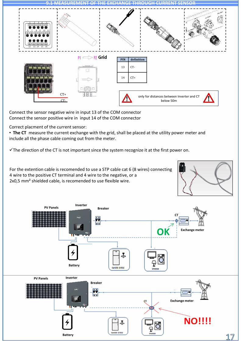
Correct placment of the current sensor:• The CT measure the current exchange with the grid, shall be placed at the utility power meter and include all the phase cable coming out from the meter.
The direction of the CT is not important since the system recognize it at the first power on.
Connect the sensor negative wire in input 13 of the COM connectorConnect the sensor positive wire in input 14 of the COM connector
OK
InverterPV Panels
For the extention cable is recomended to use a STP cable cat 6 (8 wires) connecting4 wire to the positive CT terminal and 4 wire to the negative, or a2x0,5 mm² shielded cable, is recomended to use flexible wire.
CT
Interruttore di protezione
9.1 MEASUREMENT OF THE EXCHANGE THROUGH CURRENT SENSOR
Breaker
Exchange meter
PIN definition
13 CT-
14 CT+
+ + + + +
+ + + + +
+ + + + ++
12 13 14 15 16
CT+
CT-only for distances between Inverter and CT
below 50m
InverterPV Panels Interruttore di protezione
Exchange meter
Breaker
Battery
Battery

The sensor must include all phase cables entering or leaving the meter.
9.2 MEASUREMENT OF THE EXCHANGE POWER THROUGH METER
INVERTER PIN METER PIN Nota
16 24Exchange meter communication
15 25
Battery
PV Panels
HYD
Load
Grid
Exchange meter
Meter L N
InverterPV Panels Breaker Exchange
meter
Battery
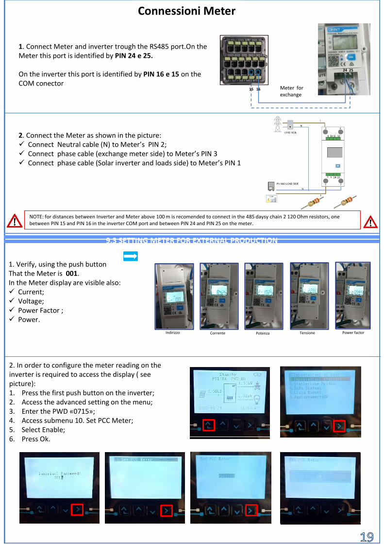
Connessioni Meter
Meter forexchange
2. Connect the Meter as shown in the picture: Connect Neutral cable (N) to Meter’s PIN 2; Connect phase cable (exchange meter side) to Meter’s PIN 3 Connect phase cable (Solar inverter and loads side) to Meter’s PIN 1
1. Connect Meter and inverter trough the RS485 port.On the Meter this port is identified by PIN 24 e 25.
On the inverter this port is identified by PIN 16 e 15 on the COM conector
1. Verify, using the push buttonThat the Meter is 001.In the Meter display are visible also: Current; Voltage; Power Factor ; Power.
NOTE: for distances between Inverter and Meter above 100 m is recomended to connect in the 485 daysy chain 2 120 Ohm resistors, onebetween PIN 15 and PIN 16 in the inverter COM port and between PIN 24 and PIN 25 on the meter.
9.3 SETTING METER FOR EXTERNAL PRODUCTION
2. In order to configure the meter reading on the inverter is required to access the display ( seepicture):1. Press the first push button on the inverter;2. Access the advanced setting on the menu;3. Enter the PWD «0715»;4. Access submenu 10. Set PCC Meter;5. Select Enable;6. Press Ok.
24 25
15 16
Indirizzo Corrente Potenza Tensione Power factor
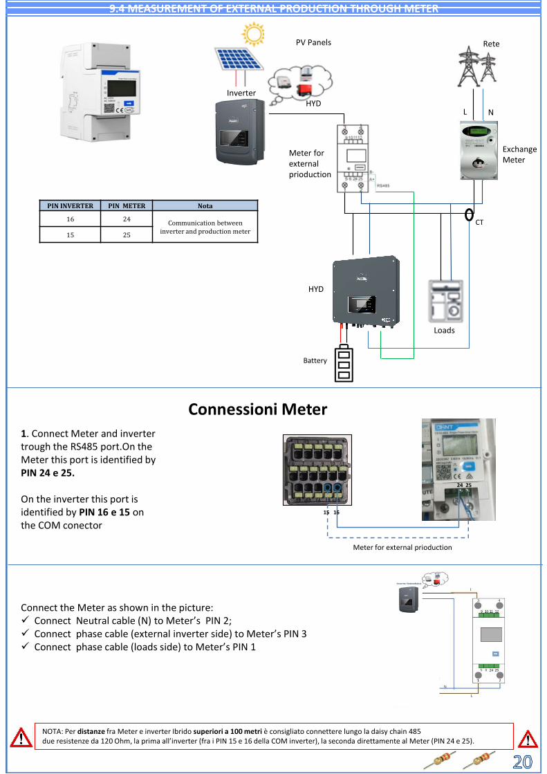
9.4 MEASUREMENT OF EXTERNAL PRODUCTION THROUGH METER
PIN INVERTER PIN METER Nota
16 24 Communication betweeninverter and production meter15 25
Battery
CT
Connessioni Meter
Meter for external prioduction
Connect the Meter as shown in the picture: Connect Neutral cable (N) to Meter’s PIN 2; Connect phase cable (external inverter side) to Meter’s PIN 3 Connect phase cable (loads side) to Meter’s PIN 1
1. Connect Meter and inverter trough the RS485 port.On the Meter this port is identified byPIN 24 e 25.
On the inverter this port isidentified by PIN 16 e 15 on the COM conector
NOTA: Per distanze fra Meter e inverter Ibrido superiori a 100 metri è consigliato connettere lungo la daisy chain 485 due resistenze da 120 Ohm, la prima all’inverter (fra i PIN 15 e 16 della COM inverter), la seconda direttamente al Meter (PIN 24 e 25).
PV Panels
HYD
Exchange Meter
L N
Rete
Loads
Meter forexternalprioduction
Inverter
HYD
24 25
15 16
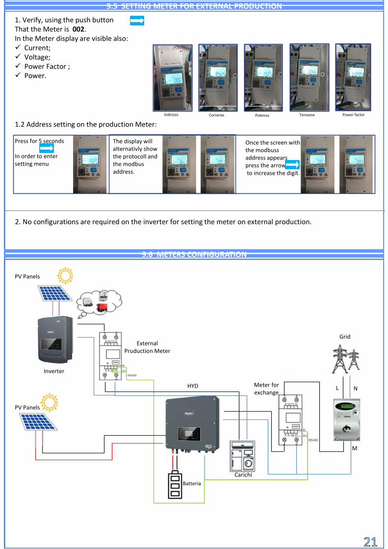
1. Verify, using the push buttonThat the Meter is 002.In the Meter display are visible also: Current; Voltage; Power Factor ; Power.
Indirizzo Corrente Potenza Tensione Power factor
9.5 SETTING METER FOR EXTERNAL PRODUCTION
2. No configurations are required on the inverter for setting the meter on external production.
9.6 METERS CONFIGURATION
1.2 Address setting on the production Meter:
Press for 5 seconds
In order to entersetting menu
The display willalternativly show the protocoll and the modbusaddress.
Once the screen withthe modbussaddress appearspress the arrowto increase the digit.
Batteria
PV Panels
M
L N
Grid
Carichi
Meter forexchange
Inverter
HYD
PV Panels
ExternalPruduction Meter
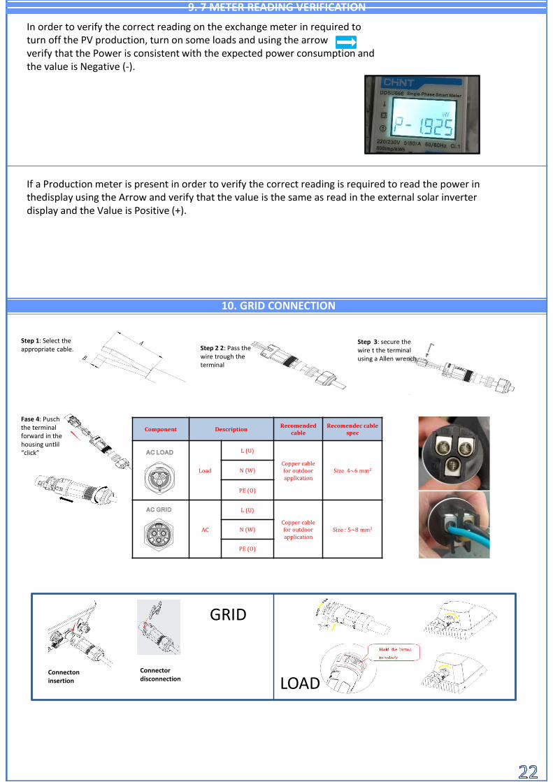
10. GRID CONNECTION
Step 1: Select the appropriate cable. Step 2 2: Pass the
wire trough the terminal
Step 3: secure the wire t the terminal using a Allen wrench
Fase 4: Puschthe terminal forward in the housing untlil“click”
Connectoninsertion
Connectordisconnection
GRID
LOAD
Component DescriptionRecomended
cableRecomendec cable
spec
Load
L (U)
Copper cablefor outdoor application
Size 4~6 mm2N (W)
PE (O)
AC
L (U)
Copper cablefor outdoor application
Size : 5~8 mm2N (W)
PE (O)
9. 7 METER READING VERIFICATION
In order to verify the correct reading on the exchange meter in required toturn off the PV production, turn on some loads and using the arrowverify that the Power is consistent with the expected power consumption and the value is Negative (-).
If a Production meter is present in order to verify the correct reading is required to read the power in thedisplay using the Arrow and verify that the value is the same as read in the external solar inverter display and the Value is Positive (+).
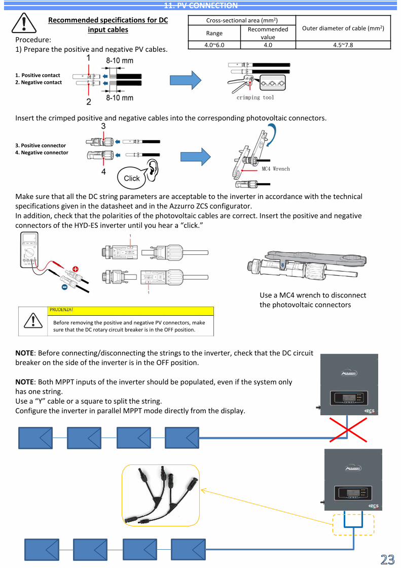
Cross-sectional area (mm2)Outer diameter of cable (mm2)
Range Recommended value
4.0~6.0 4.0 4.5~7.8
Recommended specifications for DC input cables
Procedure:1) Prepare the positive and negative PV cables.
Insert the crimped positive and negative cables into the corresponding photovoltaic connectors.
1. Positive contact 2. Negative contact
3. Positive connector 4. Negative connector
Make sure that all the DC string parameters are acceptable to the inverter in accordance with the technical specifications given in the datasheet and in the Azzurro ZCS configurator.In addition, check that the polarities of the photovoltaic cables are correct. Insert the positive and negative connectors of the HYD-ES inverter until you hear a “click.”
Use a MC4 wrench to disconnect the photovoltaic connectors
NOTE: Both MPPT inputs of the inverter should be populated, even if the system only has one string.Use a “Y” cable or a square to split the string.Configure the inverter in parallel MPPT mode directly from the display.
11. PV CONNECTION
NOTE: Before connecting/disconnecting the strings to the inverter, check that the DC circuit breaker on the side of the inverter is in the OFF position.
Before removing the positive and negative PV connectors, make sure that the DC rotary circuit breaker is in the OFF position.

OFF
HYD 3-6-HP GRID
8888
> 200W
Current flow
Loads
Import/Export meter
Turn on the batteries:
12. START UP PROCEDURE
Turn ON the AC circuit breaker located between the inverter and AC grid.
Inverter Ibrido RETE
ON
To supply DC voltage to the hybrid inverter, turn the switch to the ON position
Make sure that the AC circuit breaker of the hybrid inverter is open and that no voltage is present on the inverter's terminal block.
Check that the DC circuit breaker of the inverter is in the OFF position.
Make sure there is a domestic load of at least 200 W by using a current clamp to measure under the import/export meter.
In case of WeCo or Azzurro batteries, press the POWER button of each battery for 1 second, the RUN LED will turn on and the internal contactor will close automatically.
To turn on the Pylontech batteries: bring the switch on the front of all the batteries to the ON position.
Press the red SW button of a single battery for one second, the internal contactor will close automatically.

IMPORTANT: Always have a PC and USB memory in order to set the correct countrystandard and perform firmware upgrade
13. FIRST CONFIGURATION
Parameter Nota
1. Language OSD The default language is English
2. Date and time setting
*3. Safety parameters settingThe safety parameters need to be downloaded from the Azzurro webpageand upload in the inverter using a USB memory.
*4Battery paramenters setting
5. Configuration completed
back
Incrementa numero
Decrementa numero
Avanza o conferma
To write data and hour
1 setting
2. Date and timeDate and hour
*3. Safety parameters setting (country code)
1.Basic setting
3.Safety parameters
1. 001-000-CEI-021 Internal
4.3 Impostazioni di prima configurazione – Batteria1.Advanced setting
1.Battery paramenters
1. Battery Type
2. Depth of discharge
3. Save*
“Password 0001”1.PYLON (PYLONTECH)
4.GENERAL LITHIUM (WECO)
Depth of discharge
50%
Depth of dischargeEPS
80%
Safety Buffer
10%
* After setting the parametermake sure to press save (point 3)
2.AZZURRIO
*2. Time and date setting
*4. Battery parameters setting
In order to set the country is required to insert on a USB memory the safety folder ( unzipped) available at : https://www.zcsazzurro.com/it/documentazione/azzurro-hybrid-storage-inverter-single-phase-ep5kw
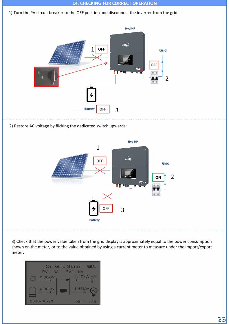
1) Turn the PV circuit breaker to the OFF position and disconnect the inverter from the grid
3) Check that the power value taken from the grid display is approximately equal to the power consumption shown on the meter, or to the value obtained by using a current meter to measure under the import/export meter.
Hyd HP
OFF
Grid
ON
NA NA
OFF1
2
14. CHECKING FOR CORRECT OPERATION
2) Restore AC voltage by flicking the dedicated switch upwards:
Hyd HP
GridOFF
Battery OFF
Battery
3
1
2
3OFF

Once the PV production start verify that:
the comsumption value does not change *.
Nota: If the above condition are not verified check the correct position and settingof the power Meter.
* Check that the power of the loads in use does not change: • Heat pump or pump → Load variable over me• Light or Hairdryer → Load constant over me
HYD - HP
ON
GRID
OFF
ON2) Turn on the PV switch
HYD - HP
ON
GRIDON1
2
Battery
ON 3
1
2
3
2) Turn on the batteries and verify that the system will work as described on the paragraph SELF-USE WORKING MODE:•PV>Load →Battery is charging•PV<Load Battery is discharging•PV=Load Battery is in stanby
Note: When using WeCo or Azzurro batteries at the first power on the Batterywill charge from the grid until ridge 100%
Battery
PV Panels
PV Panels
Max inverter power
Serial number of the machine
Software version
Hardware version
Info Inverter (1)Serial number:
ZM2ES060MBG265Hardware Version :
Software Version :V001
Press enter to view!Safety firmware version:
V02000
Information on DRMs0 mode (to enabled only for Australia)
Info Inverter (4)
Logic interface:Disabled
Info Inverter (2)Country: 001-000 Country code for legislation
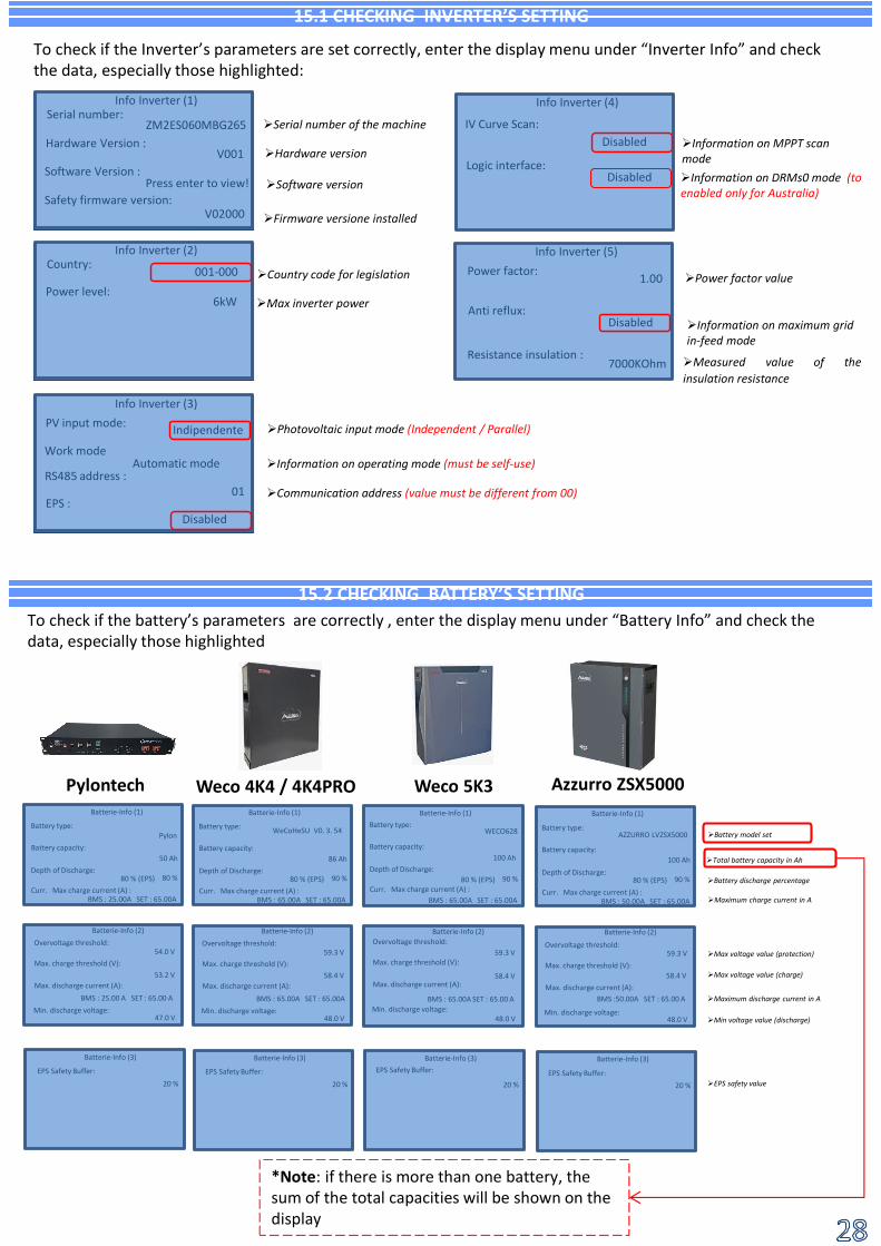
15.2 CHECKING BATTERY’S SETTING
15.1 CHECKING INVERTER’S SETTING
To check if the Inverter’s parameters are set correctly, enter the display menu under “Inverter Info” and check the data, especially those highlighted:
Power level:6kW
Firmware versione installed
Measured value of theinsulation resistance
Info Inverter (5)
Resistance insulation :7000KOhm
Photovoltaic input mode (Independent / Parallel)
Info Inverter (3)PV input mode:
Work mode
Indipendente
Automatic mode Information on operating mode (must be self-use)RS485 address :
01 Communication address (value must be different from 00)EPS :
Disabled
IV Curve Scan:Disabled
Information on maximum grid in-feed mode
Anti reflux:Disabled
Information on MPPT scan mode
Power factor valuePower factor: 1.00
To check if the battery’s parameters are correctly , enter the display menu under “Battery Info” and check the data, especially those highlighted
Battery model set
Batterie-Info (1)
Battery type:Pylon
Battery capacity:
Depth of Discharge:50 Ah
80 %
BMS : 25.00A SET : 65.00ACurr. Max charge current (A) :
Batterie-Info (2)
Overvoltage threshold:54.0 V
Max. charge threshold (V):53.2 V
Max. discharge current (A):
Min. discharge voltage:47.0 V
BMS : 25.00 A SET : 65.00 A
80 % (EPS)
*Note: if there is more than one battery, the sum of the total capacities will be shown on the display
Batterie-Info (3)
EPS Safety Buffer:
20 %
Batterie-Info (1)
86 Ah
90 %
BMS : 65.00A SET : 65.00A
Batterie-Info (2)
59.3 V
58.4 V
48.0 V
BMS : 65.00A SET : 65.00A
80 % (EPS)
Batterie-Info (3)
20 %
WeCoHeSU V0. 3. 54
Batterie-Info (1)
100 Ah
90 %
BMS : 65.00A SET : 65.00A
Batterie-Info (2)
59.3 V
58.4 V
48.0 V
BMS : 65.00A SET : 65.00 A
80 % (EPS)
Batterie-Info (3)
20 %
WECO628
Batterie-Info (1)
100 Ah
90 %
BMS : 50.00A SET : 65.00A
Batterie-Info (2)
59.3 V
58.4 V
48.0 V
BMS :50.00A SET : 65.00 A
80 % (EPS)
Batterie-Info (3)
20 %
AZZURRO LVZSX5000
Pylontech Weco 4K4 / 4K4PRO Weco 5K3 Azzurro ZSX5000
Max voltage value (charge)
Maximum discharge current in A
Min voltage value (discharge)
EPS safety value
Total battery capacity in Ah
Battery discharge percentage
Maximum charge current in A
Battery type:
Battery capacity:
Depth of Discharge:
Curr. Max charge current (A) :
Overvoltage threshold:
Max. charge threshold (V):
Max. discharge current (A):
Min. discharge voltage:
EPS Safety Buffer:
Battery type:
Battery capacity:
Depth of Discharge:
Curr. Max charge current (A) :
Overvoltage threshold:
Max. charge threshold (V):
Max. discharge current (A):
Min. discharge voltage:
EPS Safety Buffer:
Battery type:
Battery capacity:
Depth of Discharge:
Curr. Max charge current (A) :
Overvoltage threshold:
Max. charge threshold (V):
Max. discharge current (A):
Min. discharge voltage:
EPS Safety Buffer:
Max voltage value (protection)
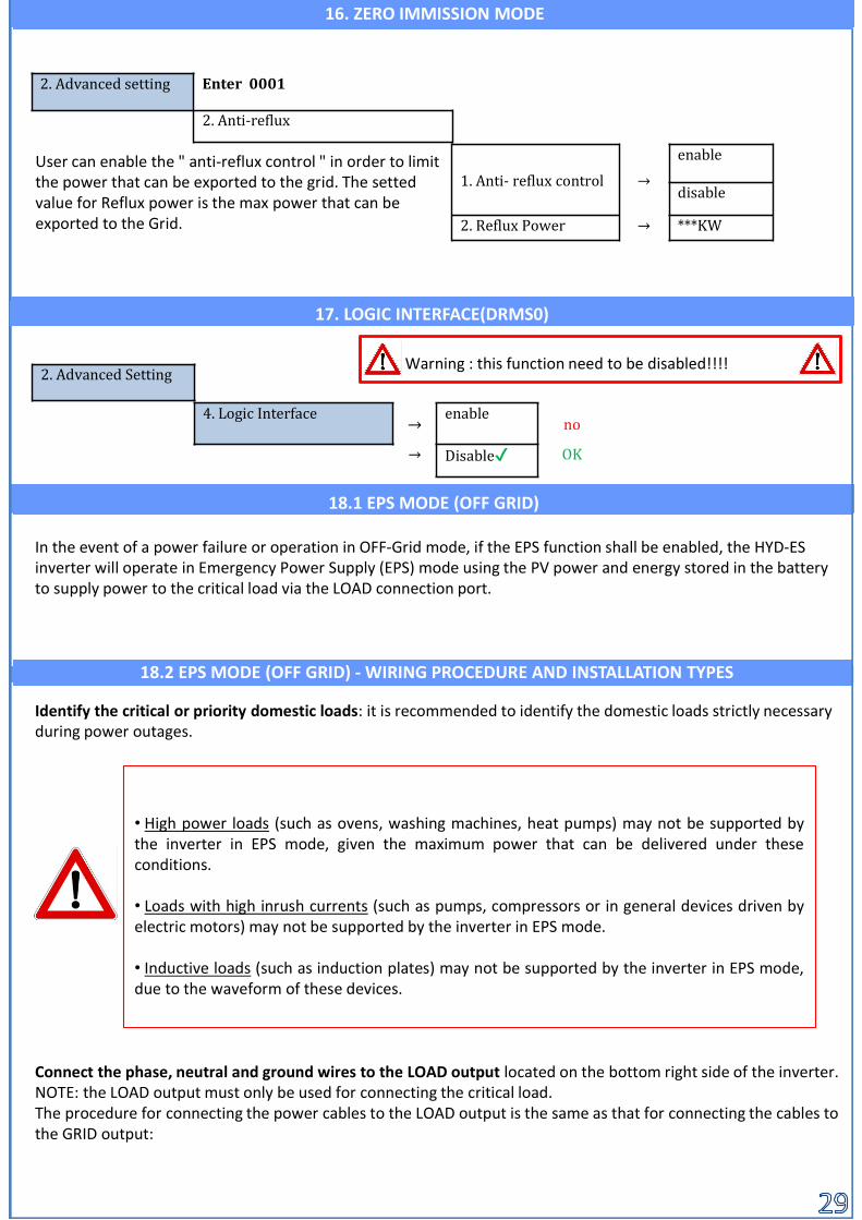
In the event of a power failure or operation in OFF-Grid mode, if the EPS function shall be enabled, the HYD-ES inverter will operate in Emergency Power Supply (EPS) mode using the PV power and energy stored in the battery to supply power to the critical load via the LOAD connection port.
• High power loads (such as ovens, washing machines, heat pumps) may not be supported bythe inverter in EPS mode, given the maximum power that can be delivered under theseconditions.
• Loads with high inrush currents (such as pumps, compressors or in general devices driven byelectric motors) may not be supported by the inverter in EPS mode.
• Inductive loads (such as induction plates) may not be supported by the inverter in EPS mode,due to the waveform of these devices.
Identify the critical or priority domestic loads: it is recommended to identify the domestic loads strictly necessary during power outages.
Connect the phase, neutral and ground wires to the LOAD output located on the bottom right side of the inverter.NOTE: the LOAD output must only be used for connecting the critical load.The procedure for connecting the power cables to the LOAD output is the same as that for connecting the cables to the GRID output:
18.2 EPS MODE (OFF GRID) - WIRING PROCEDURE AND INSTALLATION TYPES
18.1 EPS MODE (OFF GRID)
16. ZERO IMMISSION MODE
2. Advanced setting Enter 0001
2. Anti-reflux
1. Anti- reflux control →
enable
disable
2. Reflux Power → ***KW
User can enable the " anti-reflux control " in order to limitthe power that can be exported to the grid. The settedvalue for Reflux power is the max power that can beexported to the Grid.
17. LOGIC INTERFACE(DRMS0)
4. Logic Interface→
enableno
→ Disable✔ OK
2. Advanced SettingWarning : this function need to be disabled!!!!

CHANGE-OVER SWITCHIs recommended to install a change-over switch in order to be able to disconnect the load from power during maintenance operation or to connect the load to the grid in case of inverter failure.
DOUBLE SWITCH CONTACTORIn some circumstances, a double switch contactor can be installed. This device will ensure that the critical loads are normally powered by the grid, they will be powered by the EPS LOAD line of the inverter only in the event of a power failure thanks to the change-over of the contactors
230V
230V
If AC voltage supplied by the grid is present (normal operating condition), both the standard loads of the system and the priority or critical loads are supplied by the grid as shown in the figure below.
the LOAD output is always energised, even when the mains voltage is present.
Position 1→ Priority loads connected and powered by the inverter's LOAD line
Position 0→ Priority loads not powered by the inverter or by the grid
Position 2→ Priority loads connected and powered by the grid
18.3 EPS MODE (OFF GRID) - OPERATION
CHANGE-OVER SWITCH
CRITILCAL LOADS
GRID
Note: If the hybrid inverter is installed under different conditions from those shown in the diagrams above, contact technical support to check whether it is feasible.
NOTE: For the conditions described above, in the event of a power failure, the part of the system powered bythe inverter's LOAD port behaves like an IT system
0 0
F
N
F
N
PE
PEGRID
LOAD
F
N
PE
F
N
PE
2. Advanced Setting
1. Battery parameters
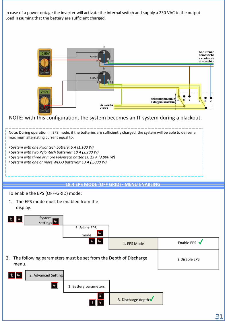
3. Discharge depth✔
System settings
5. Select EPS
mode
1. EPS Mode Enable EPS ✔
2.Disable EPS
To enable the EPS (OFF-GRID) mode:
1. The EPS mode must be enabled from the display.
2. The following parameters must be set from the Depth of Discharge menu.
Note: During operation in EPS mode, if the batteries are sufficiently charged, the system will be able to deliver a maximum alternating current equal to:
• System with one Pylontech battery: 5 A (1,100 W)• System with two Pylontech batteries: 10 A (2,200 W)• System with three or more Pylontech batteries: 13 A (3,000 W)• System with one or more WECO batteries: 13 A (3,000 W)
In case of a power outage the inverter will activate the internal switch and supply a 230 VAC to the output Load assuming that the battery are sufficient charged.
230V
0.00V
18.4 EPS MODE (OFF GRID) - MENU ENABLING
NOTE: with this configuration, the system becomes an IT system during a blackout.
F
N
PE
F
N
PE

The Inverter HYD-ES can be used in Stand Alone system .The energy provided by the Solar panel canbe stored in the batteries and provided to the load connected to the AC load Inverter. EPS functionneed to be enabled (Emergency Power Supply).
Verifyck that the DC circuit breaker of the inverter is in the OFF position.
1)
2) Turn on the batteries:
Switch on the photovoltaic system by turning the switch to the ON position.
3)
ON
In case of WeCo batteries, press the POWER button of each battery for 1 second, the RUN LED will turn on and the internal contactor will close automatically.
To turn on the Pylontech batteries: set the switch on the front of all the batteries to the ON position.
Press the red SW button of a single battery for one second, the internal contactor will close automatically.
19.1 OFF GRID MODE
19.2 OFF GRID MODE ONLY - START UP
PV Panels
IBRIDO
Critical Load
*** The max power that can be provided depend on the battery number and Models and also enviromentlcondition
BAtteries

20.1 PARALLEL INVERTER MODE- CONFIGURATION
1.The inverters need to be connected using the cable provided in the inverter box as described below:•Link port 0 Master inverter→ connected to the termination resistor (8 pin )•Link port 1 Master inverter → Link port 0 Slave 1 inverter•Link port 1 Slave 1 Inverter → Link port 0 Slave 2 Inverter•Link port 1 Slave 2 Inverter→ Link port 0 Slave 3 Inverter•...•Link port 1 Slave n-1 Inverter→ Link port 0 Slave n InverterInverter•Link port 1 Slave n Inverter → connected to the termination resistor (8 pin )Note: The termination resistors are provided in the inverter boxNOTE: The connection cable is provided with the inverter, is 3 meters long and cannot be extended.
2.If the inverter are all the same size is possible to parallel the LOAD output. When doing that is required to makesure that the connection to the parallel box of each inverter have: • Low impedance•Same lenght•Same section size .
3.Total load connected shall be less than the maximum available from the Inverter4.Meters shall be connected to the Master inverter (Primary)
Al primo ed all’ultimo inverter devono essere connesse le resistenze di terminazione (fornite in dotazione )
Cavo connessione parallelo fornito in dotazione di lunghezza 2,5m
2. Impostazioni avanzatePsw 00016.Impostazioni parallelo
OK 1.Parallel Control Enable / disable
2.Parallel Master-Slave Primary / Replica
3.Parallel Address 00 (Primary)
01 (replica 1)
…
0n (Replica n)
4.Save ok
20.2 PARALLEL INVERTERS MODE- SETTING
Enable
Primary
00
ok
Enable
Replica
01
ok
Enable
Replica
02
ok
Enable
Replica
03
ok
6
14.
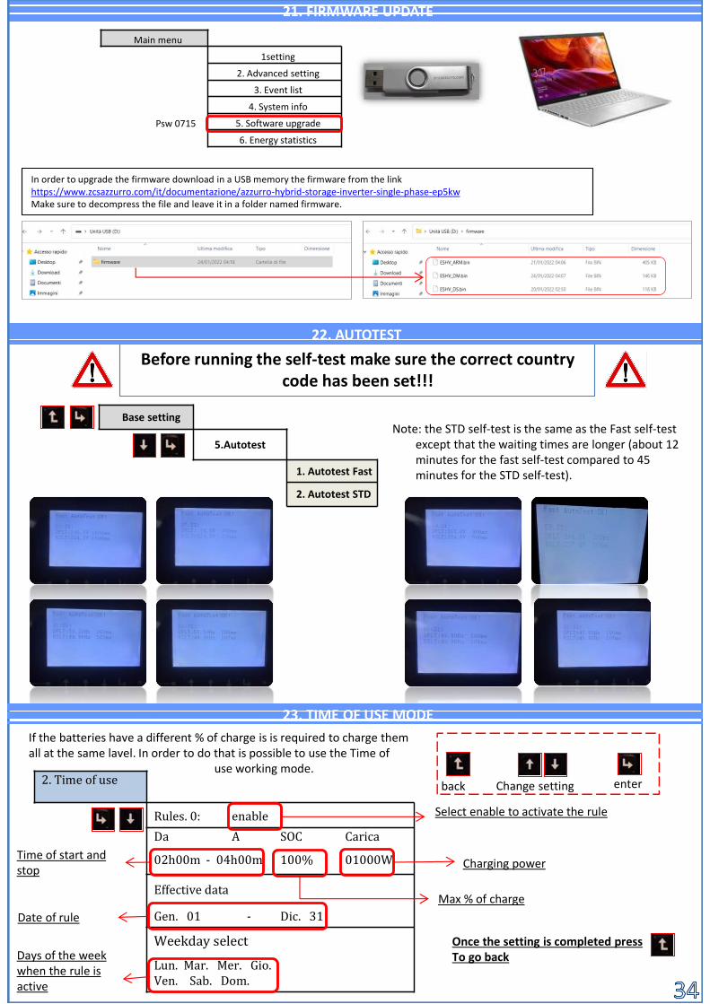
Note: the STD self-test is the same as the Fast self-test except that the waiting times are longer (about 12 minutes for the fast self-test compared to 45 minutes for the STD self-test).
Before running the self-test make sure the correct country code has been set!!!
Base setting
5.Autotest
1. Autotest Fast
2. Autotest STD
22. AUTOTEST
21. FIRMWARE UPDATE
14. 23. TIME OF USE MODE
2. Time of use
Rules. 0: enable
Da A SOC Carica
02h00m - 04h00m 100% 01000W
Effective data
Gen. 01 - Dic. 31
Weekday select
Lun. Mar. Mer. Gio. Ven. Sab. Dom.
Select enable to activate the rule
Time of start and stop
Max % of charge
Charging power
Date of rule
Days of the week when the rule isactive
Once the setting is completed pressTo go back
back Change setting enter
If the batteries have a different % of charge is is required to charge themall at the same lavel. In order to do that is possible to use the Time of
use working mode.
In order to upgrade the firmware download in a USB memory the firmware from the link https://www.zcsazzurro.com/it/documentazione/azzurro-hybrid-storage-inverter-single-phase-ep5kwMake sure to decompress the file and leave it in a folder named firmware.
Main menu
1setting
2. Advanced setting
3. Event list
4. System info
5. Software upgrade
6. Energy statistics
Psw 0715
Related Documents