My future ,drive and control Quick guide of PI8100 operation Service center in powtran technology company

Quick Guide of PI8100 Operation6-7
Oct 29, 2015
VDF
Welcome message from author
This document is posted to help you gain knowledge. Please leave a comment to let me know what you think about it! Share it to your friends and learn new things together.
Transcript
My future ,drive and control
Quick guide of PI8100 operation
Service center in powtran technology company

My future ,drive and control
1.Examples of connections between the Inverter
typical peripheral devices are shown.
Service center in powtran technology company
The Red mark is
Not option equipment
Please refer to “APPLICATION OF
OPTIONAL EQUIPMENT ”.
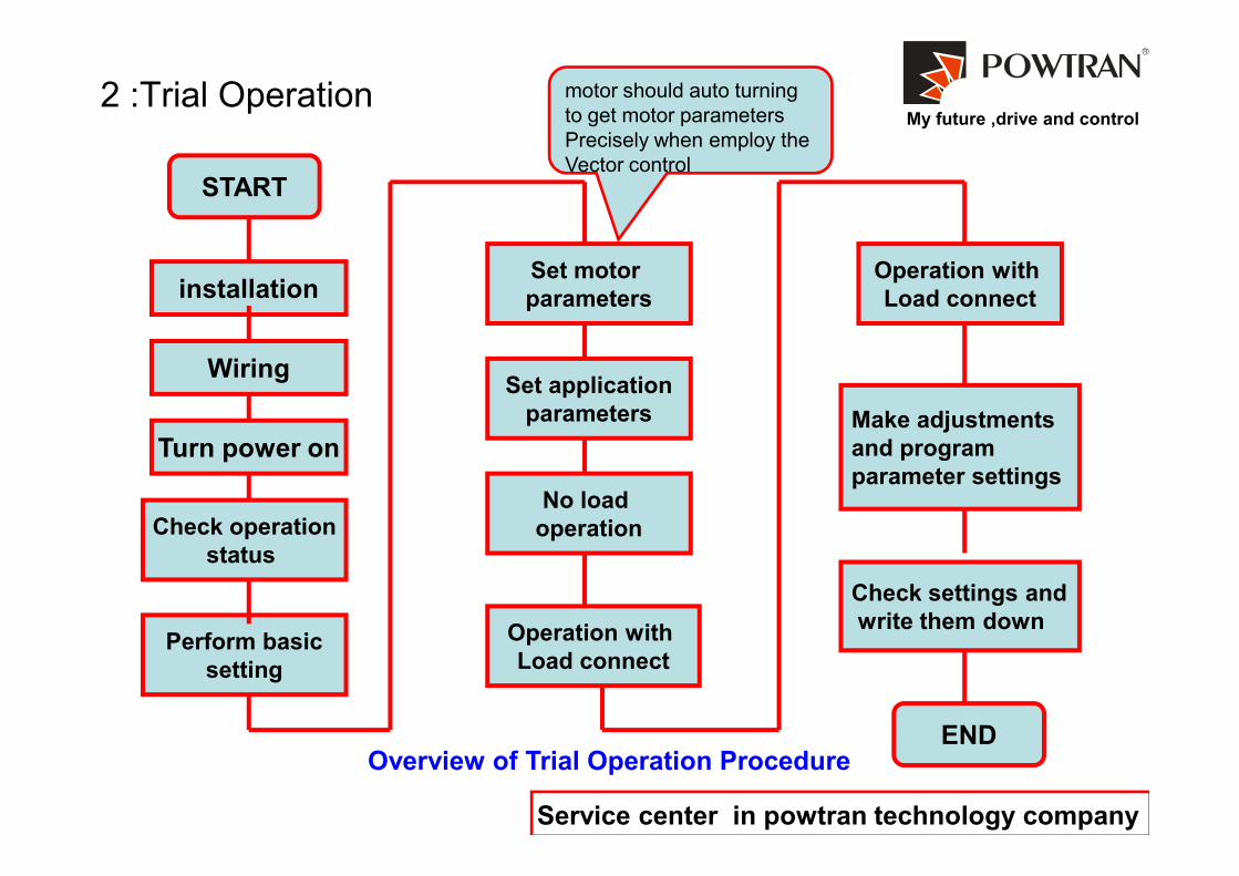
My future ,drive and control2 :Trial Operation
START
installation
Wiring
Turn power on
Set motor
parameters
Set application
parameters
Operation with
Load connect
Make adjustments
and program
motor should auto turning
to get motor parameters
Precisely when employ the
Vector control
Service center in powtran technology company
Overview of Trial Operation Procedure
Turn power on
Check operation
status
Perform basic
setting
No load
operation
Operation with
Load connect
and program
parameter settings
Check settings and
write them down
END
My future ,drive and control
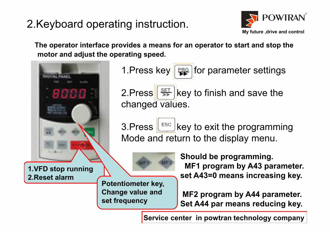
2.Keyboard operating instruction.
The operator interface provides a means for an operator to start and stop the
motor and adjust the operating speed.
1.Press key for parameter settings
2.Press key to finish and save the
changed values.
Service center in powtran technology company
3.Press key to exit the programming
Mode and return to the display menu.
1.VFD stop running
2.Reset alarmPotentiometer key,
Change value and
set frequency
Should be programming.
MF1 program by A43 parameter.
set A43=0 means increasing key.
MF2 program by A44 parameter.
Set A44 par means reducing key.

My future ,drive and control
F00: V/F control, Factory set to 0
F01: Keyboard Setting frequency , 50Hz
3.1 in common use parameters
B00 Motor rated frequency
B01 Motor rated current
Motor rated voltage
Motor pole-pairs
Motor rated speed
O15 use for programming DA1 analog output
O16 use for programming DA2 analog output
O21 use for programming SPA output signal
O22 use for programming SPB output signal
O23 use for programming contractor output signal 1
O24 use for programming contractor output signal 2
O36 stand for input terminal DI1,
O37 stand for input terminal DI2B.
1. Please configure the motor
parameter according the
Motor plate.
Service center in powtran technology company
F01: Keyboard Setting frequency , 50Hz
F02: Use AI1(external analog setting) ,1
F05: Running mode ,set to (I/O terminal control) 3
F09: Accelerate Time ,set to 10sec.
F10: Decelerate Time, set to 10sec.
F11: % of Output Voltage, set to 100 %
F12: Maximum Frequency, set to 50Hz
F13: Minimum Speed ,set to 20Hz
F14: Maximum Speed ,set to 50Hz
F16: Carrier Freq. can be changed (1.0 to 16.0kHz)
to reduce Motor generated noise but will increase
temperature of motor.
3.The I/O parameters
should be configure
when employ the I/O
terminal interface !
2.Application
parameters should
be set by site
requirement .
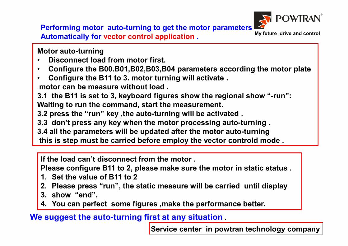
My future ,drive and controlPerforming motor auto-turning to get the motor parameters
Automatically for vector control application .
Motor auto-turning
• Disconnect load from motor first.
• Configure the B00.B01,B02,B03,B04 parameters according the motor plate
• Configure the B11 to 3. motor turning will activate .
motor can be measure without load .
3.1 the B11 is set to 3, keyboard figures show the regional show “-run”:
Waiting to run the command, start the measurement.
3.2 press the “run” key ,the auto-turning will be activated .
3.3 don’t press any key when the motor processing auto-turning .
Service center in powtran technology company
3.3 don’t press any key when the motor processing auto-turning .
3.4 all the parameters will be updated after the motor auto-turning
this is step must be carried before employ the vector controld mode .
If the load can’t disconnect from the motor .
Please configure B11 to 2, please make sure the motor in static status .
1. Set the value of B11 to 2
2. Please press “run”, the static measure will be carried until display
3. show “end”.
4. You can perfect some figures ,make the performance better.
We suggest the auto-turning first at any situation .
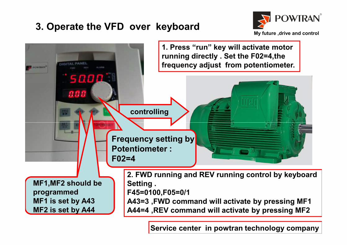
My future ,drive and control3. Operate the VFD over keyboard
controlling
1. Press “run” key will activate motor
running directly . Set the F02=4,the
frequency adjust from potentiometer.
Service center in powtran technology company
Frequency setting by
Potentiometer :
F02=4
MF1,MF2 should be
programmed
MF1 is set by A43
MF2 is set by A44
2. FWD running and REV running control by keyboard
Setting .
F45=0100,F05=0/1
A43=3 ,FWD command will activate by pressing MF1
A44=4 ,REV command will activate by pressing MF2
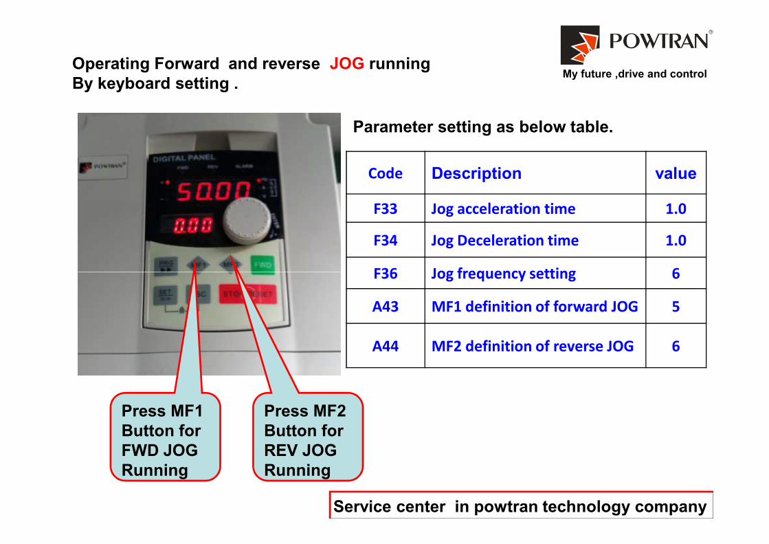
My future ,drive and controlOperating Forward and reverse JOG running
By keyboard setting .
Code Description value
F33 Jog acceleration time 1.0
F34 Jog Deceleration time 1.0
F36 Jog frequency setting 6
Parameter setting as below table.
Service center in powtran technology company
Press MF1
Button for
FWD JOG
Running
Press MF2
Button for
REV JOG
Running
F36 Jog frequency setting 6
A43 MF1 definition of forward JOG 5
A44 MF2 definition of reverse JOG 6
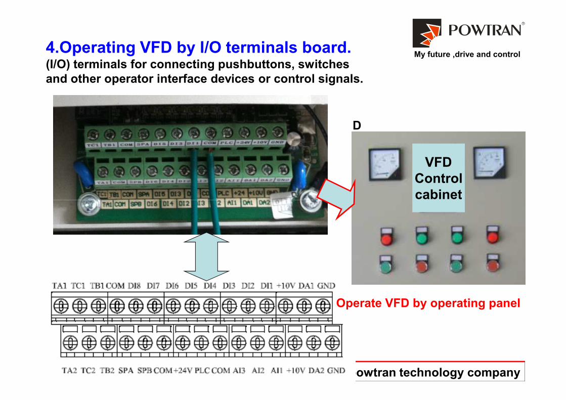
My future ,drive and control4.Operating VFD by I/O terminals board.(I/O) terminals for connecting pushbuttons, switches
and other operator interface devices or control signals.
D
VFD
Control
cabinet
Service center in powtran technology company
cabinet
Operate VFD by operating panel
My future ,drive and control
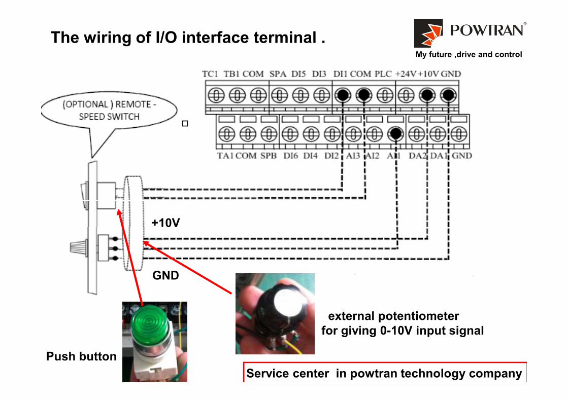
The wiring of I/O interface terminal .
Service center in powtran technology company
external potentiometer
for giving 0-10V input signal
Push button
+10V
GND
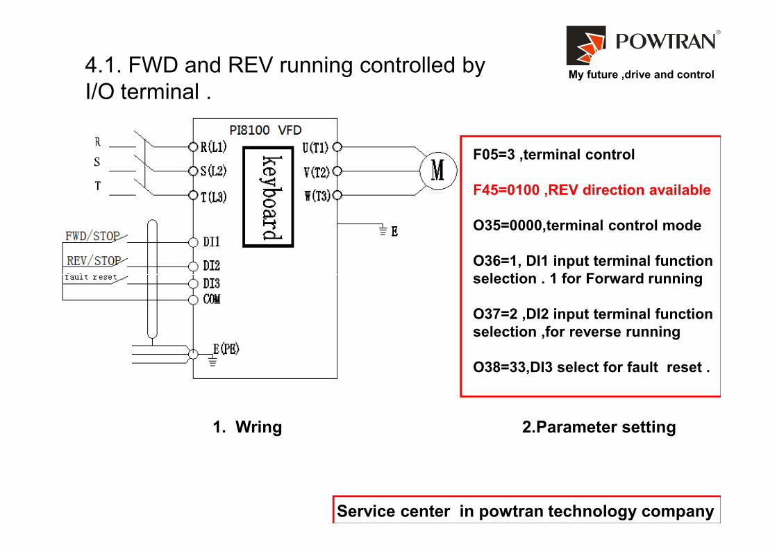
My future ,drive and control4.1. FWD and REV running controlled by
I/O terminal .
F05=3 ,terminal control
F45=0100 ,REV direction available
O35=0000,terminal control mode
O36=1, DI1 input terminal function
selection . 1 for Forward running
Service center in powtran technology company
1. Wring
selection . 1 for Forward running
O37=2 ,DI2 input terminal function
selection ,for reverse running
O38=33,DI3 select for fault reset .
2.Parameter setting

My future ,drive and control4.2. JOG for FWD and REV running controlled
by I/O terminal .
F05=3 ,terminal control
F45=0100 ,REV direction available
O35=0000,terminal control mode
O36=34, DI1 input terminal function
Service center in powtran technology company
Wring
selection . 34 for Forward JOG
command
O37=35 , DI2 input terminal
function selection . 35 for REV
JOG command
Parameter setting
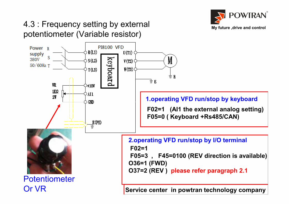
My future ,drive and control4.3 : Frequency setting by external
potentiometer (Variable resistor)
1.operating VFD run/stop by keyboard
Service center in powtran technology company
Potentiometer
Or VR
F02=1 (AI1 the external analog setting)
F05=0 ( Keyboard +Rs485/CAN)
1.operating VFD run/stop by keyboard
2.operating VFD run/stop by I/O terminal
F02=1
F05=3 , F45=0100 (REV direction is available)
O36=1 (FWD)
O37=2 (REV ) please refer paragraph 2.1

My future ,drive and control4.3 : Frequency setting by external
potentiometer (Variable resistor)
1.operating VFD run/stop by keyboard
JP5 cut/JP3 1-2: -10V~+10V
JP5 cut/JP3 2-3: 0~10V
JP5 connect: 0~20mA can be
regulated
o00/o01 Set the input voltage / current
range
o06/o07 Set the input signal
corresponding to set value
Service center in powtran technology company
Potentiometer
Or VR
F02=1 (AI1 the external analog setting)
F05=0 ( Keyboard +Rs485/CAN)
1.operating VFD run/stop by keyboard
2.operating VFD run/stop by I/O terminal
F02=1
F05=3 , F45=0100 (REV direction is available)
O36=1 (FWD)
O37=2 (REV ) please refer paragraph 2.1
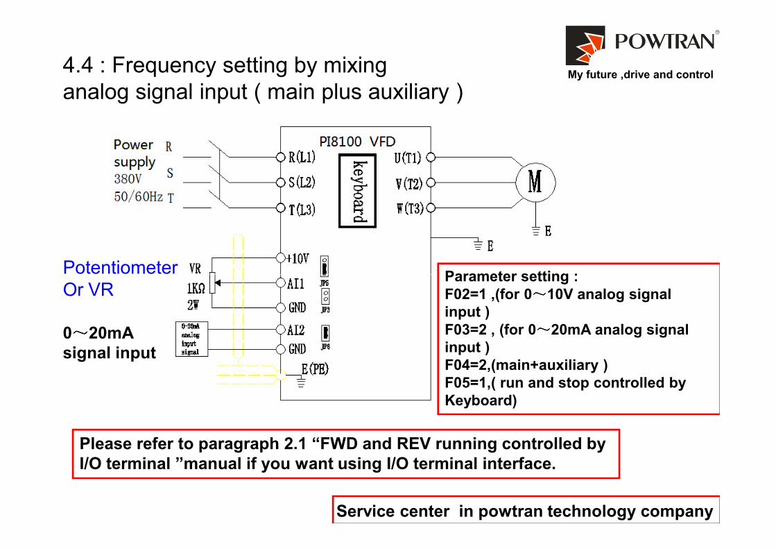
My future ,drive and control4.4 : Frequency setting by mixing
analog signal input ( main plus auxiliary )
PotentiometerParameter setting :
Service center in powtran technology company
Potentiometer
Or VR
0~~~~20mA
signal input
Parameter setting :
F02=1 ,(for 0~~~~10V analog signal
input )
F03=2 , (for 0~~~~20mA analog signal
input )
F04=2,(main+auxiliary )
F05=1,( run and stop controlled by
Keyboard)
Please refer to paragraph 2.1 “FWD and REV running controlled by
I/O terminal ”manual if you want using I/O terminal interface.
My future ,drive and control
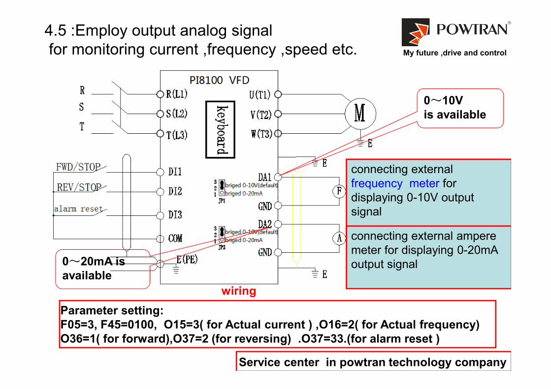
4.5 :Employ output analog signal
for monitoring current ,frequency ,speed etc.
0~~~~10V
is available
connecting external
frequency meter for
displaying 0-10V output
Service center in powtran technology company
Parameter setting:
F05=3, F45=0100, O15=3( for Actual current ) ,O16=2( for Actual frequency)
O36=1( for forward),O37=2 (for reversing) .O37=33.(for alarm reset )
wiring
0~~~~20mA is
available
displaying 0-10V output
signal
connecting external ampere
meter for displaying 0-20mA
output signal
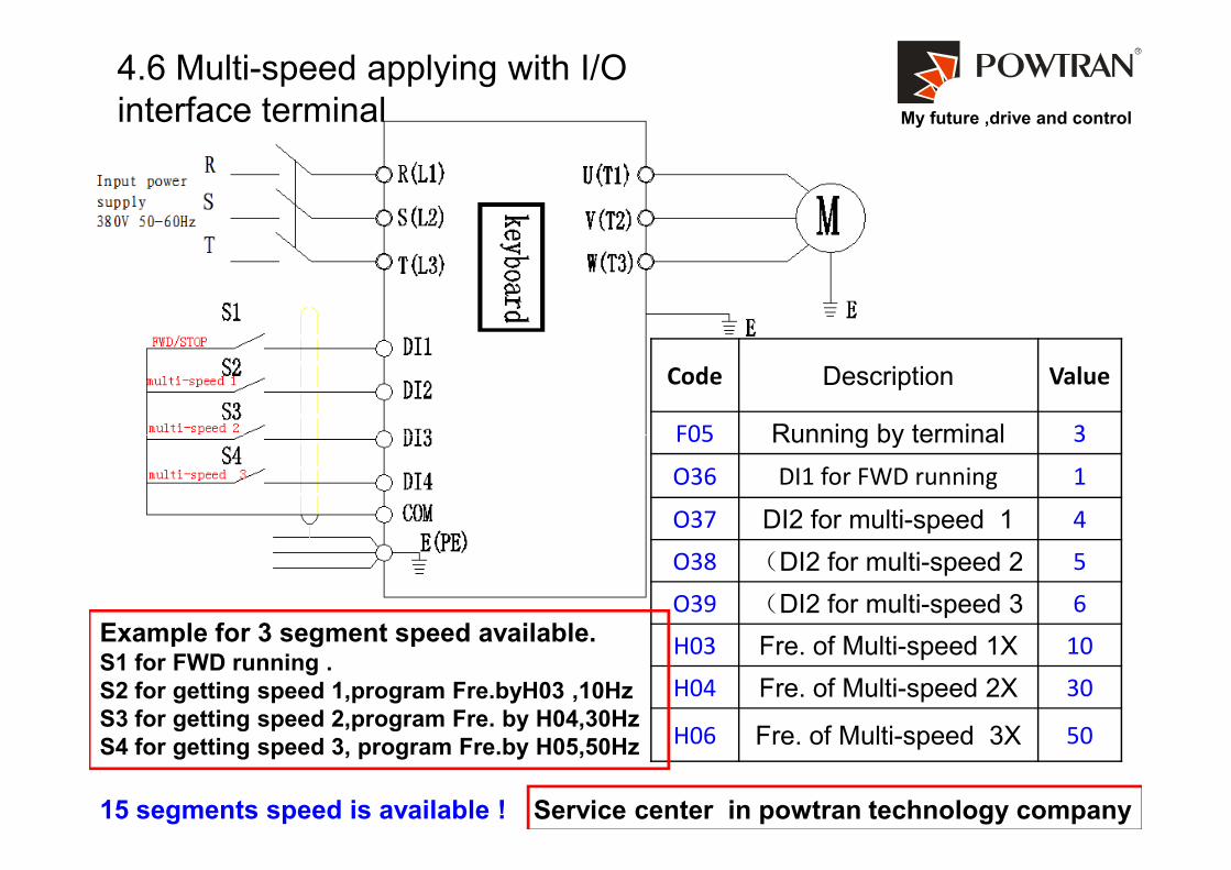
My future ,drive and control
4.6 Multi-speed applying with I/O
interface terminal
Code Description Value
F05 Running by terminal 3
Service center in powtran technology company
F05 Running by terminal 3
O36 DI1 for FWD running 1
O37 DI2 for multi-speed 1 4
O38 (DI2 for multi-speed 2 5
O39 (DI2 for multi-speed 3 6
H03 Fre. of Multi-speed 1X 10
H04 Fre. of Multi-speed 2X 30
H06 Fre. of Multi-speed 3X 50
Example for 3 segment speed available.S1 for FWD running .
S2 for getting speed 1,program Fre.byH03 ,10Hz
S3 for getting speed 2,program Fre. by H04,30Hz
S4 for getting speed 3, program Fre.by H05,50Hz
15 segments speed is available !
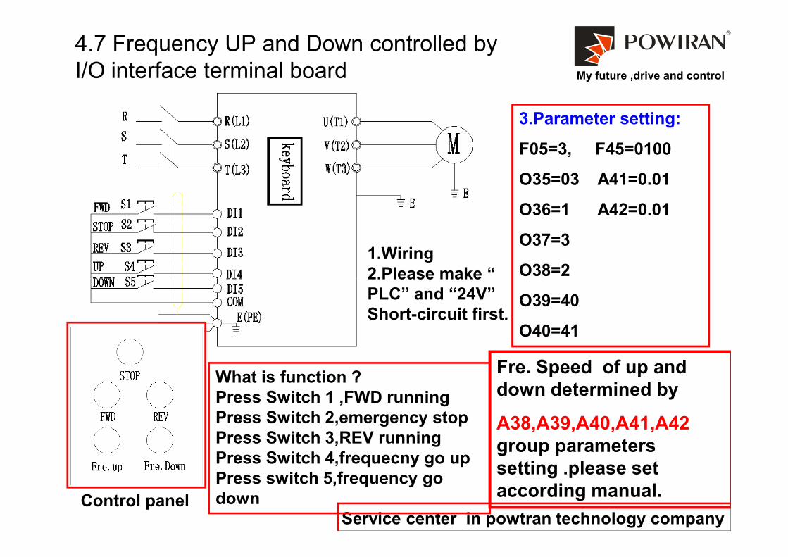
My future ,drive and control
4.7 Frequency UP and Down controlled by
I/O interface terminal board
3.Parameter setting:
F05=3, F45=0100
O35=03 A41=0.01
O36=1 A42=0.01
O37=3
O38=21.Wiring
2.Please make “
Service center in powtran technology company
What is function ?
Press Switch 1 ,FWD running
Press Switch 2,emergency stop
Press Switch 3,REV running
Press Switch 4,frequecny go up
Press switch 5,frequency go
down
O38=2
O39=40
O40=41
Fre. Speed of up and
down determined by
A38,A39,A40,A41,A42
group parameters
setting .please set
according manual.
2.Please make “
PLC” and “24V”
Short-circuit first.
Control panel

My future ,drive and control
4.8.Instruction of the proportional linkage function
1. Install the RS485 comnu. card to VFD.
2. Wiring according the electrical diagram
3.parameters setting on hosting and slave
VFD individually.
Function of proportional linkage.
1. Synchronizing speed between two or two
more motor is available .
2.Master VFD set main frequency .
3.Thin adjusting on the slave VFD is available.
Parameter setting on hosting VFD:
Service center in powtran technology company
Parameter setting on hosting VFD:
F02=1 fre. setting with AI1
A28=128,host commn. adress
A29=3 baud rate 3.9600bps ; A30=0 (commu.format)
F05=1 run/stop by I/O interface terminal.
O36=1 ,forward ;o37=reverse running
Parameters setting on slave VFD
F02=0 ,fre. Setting from or Rs485
F03=1 ,Auxiliary fre.setting from AI1 for thin adjusting fre.
F04=2 relationship between main and auxiliary fre.
F05=4 ,proportional linkage control
A28=(1-127) ,A29=3 (same as host VFD) , A30=0;
O36=39 ,DI1 for free stop,O37=40 (DI2 for fre. UP.)
O38=41 ( DI3 for Fre. Down) A43=8,A44=9,
A55=1( linkage factor)
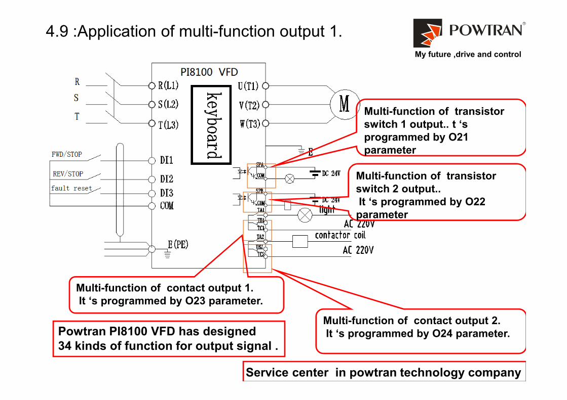
My future ,drive and control
4.9 :Application of multi-function output 1.
Multi-function of transistor
switch 1 output.. t ‘s
programmed by O21
parameter
Multi-function of transistor
switch 2 output..
It ‘s programmed by O22
Service center in powtran technology company
It ‘s programmed by O22
parameter
Multi-function of contact output 2.
It ‘s programmed by O24 parameter.
Multi-function of contact output 1.
It ‘s programmed by O23 parameter.
Powtran PI8100 VFD has designed
34 kinds of function for output signal .

My future ,drive and control
4.9 :Application of multi-function output 2.
Using the normal
Open of contactor
output .when any
happens ,pilot let turn
on. set O23=1
Service center in powtran technology company
VFD
Control
cabinet
Alarm
indicator
Ready
status
Using the normal
closed of contactor output. Once
the inverter starts ,this light will
turn on ,any alarm happens ,light
will turn off.
Set o24=1.

My future ,drive and control
4.9 :Application of multi-function output 3.
feed hopper
Conveyor belt Wheel
gear
VFD will start once the fre. of VF2 arriving at 30Hz,stop when fre. of VF2 limit 25Hz.
Start
stop
Service center in powtran technology company
Parameters setting :
O21=14 ,( arrival of FDT setting frequency 1 )
O29=30Hz,( FDT frequency setting )
O31=5, range of FDT inspection range
My future ,drive and control
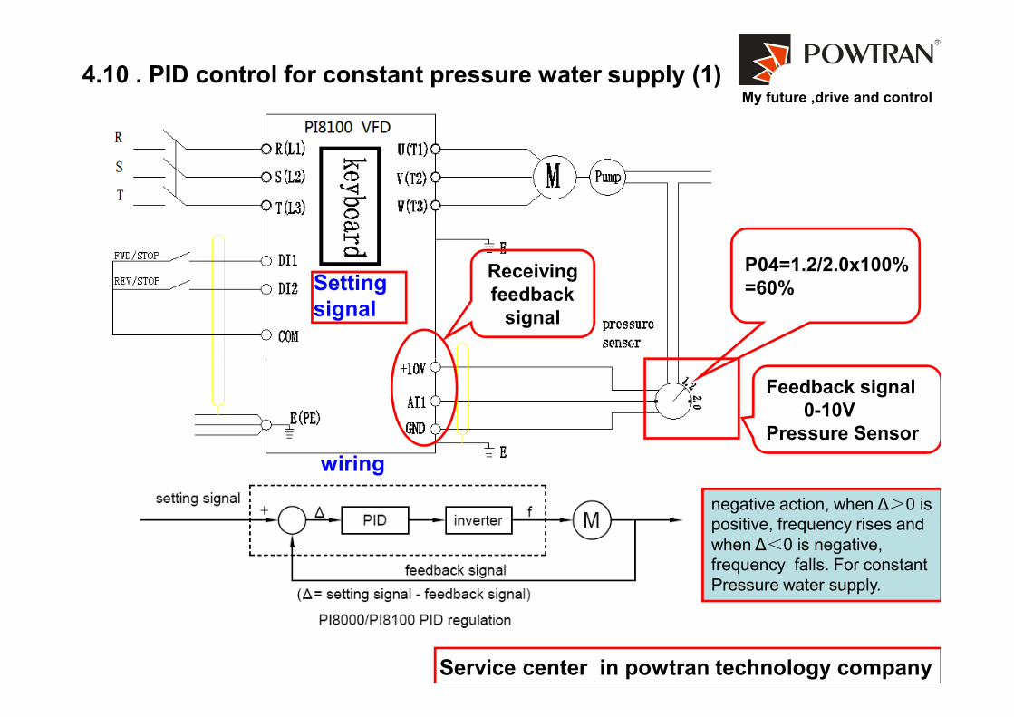
Receiving
feedback
signal
4.10 . PID control for constant pressure water supply (1)
Setting
signal
P04=1.2/2.0x100%
=60%
Service center in powtran technology company
Feedback signal
0-10V
Pressure Sensor
negative action, when ∆>0 is
positive, frequency rises and
when ∆<0 is negative,
frequency falls. For constant
Pressure water supply.
wiring
My future ,drive and control
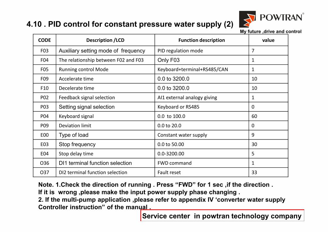
4.10 . PID control for constant pressure water supply (2)
CODE Description /LCD Function description value
F03 Auxiliary setting mode of frequency PID regulation mode 7
F04 The relationship between F02 and F03 Only F03 1
F05 Running control Mode Keyboard+terminal+RS485/CAN 1
F09 Accelerate time 0.0 to 3200.0 10
F10 Decelerate time 0.0 to 3200.0 10
P02 Feedback signal selection AI1 external analogy giving 1
P03 Setting signal selection Keyboard or RS485 0
P04 Keyboard signal 0.0 to 100.0 60
Service center in powtran technology company
P04 Keyboard signal 0.0 to 100.0 60
P09 Deviation limit 0.0 to 20.0 0
E00 Type of load Constant water supply 9
E03 Stop frequency 0.0 to 50.00 30
E04 Stop delay time 0.0-3200.00 5
O36 DI1 terminal function selection FWD command 1
O37 DI2 terminal function selection Fault reset 33
Note. 1.Check the direction of running . Press “FWD” for 1 sec ,if the direction .
If it is wrong ,please make the input power supply phase changing .
2. If the multi-pump application ,please refer to appendix IV ‘converter water supply
Controller instruction” of the manual .
Related Documents