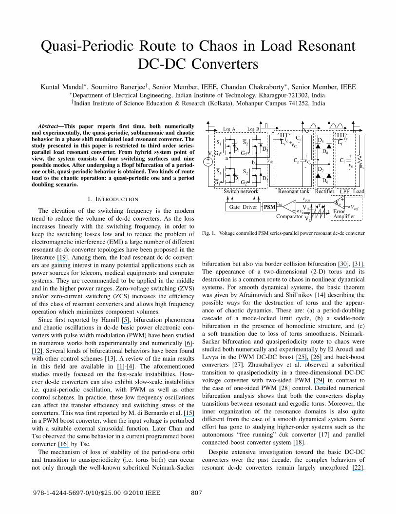
Quasi-Periodic Route to Chaos in Load Resonant DC-DC Converters Kuntal Mandal ∗ , Soumitro Banerjee † , Senior Member, IEEE, Chandan Chakraborty ∗ , Senior Member, IEEE ∗ Department of Electrical Engineering, Indian Institute of Technology, Kharagpur-721302, India † Indian Institute of Science Education & Research (Kolkata), Mohanpur Campus 741252, India Abstract—This paper reports first time, both numerically and experimentally, the quasi-periodic, subharmonic and chaotic behavior in a phase shift modulated load resonant converter. The study presented in this paper is restricted to third order series- parallel load resonant converter. From hybrid system point of view, the system consists of four switching surfaces and nine possible modes. After undergoing a Hopf bifurcation of a period- one orbit, quasi-periodic behavior is obtained. Two kinds of route lead to the chaotic operation: a quasi-periodic one and a period doubling scenario. I. I NTRODUCTION The elevation of the switching frequency is the modern trend to reduce the volume of dc-dc converters. As the loss increases linearly with the switching frequency, in order to keep the switching losses low and to reduce the problem of electromagnetic interference (EMI) a large number of different resonant dc-dc converter topologies have been proposed in the literature [19]. Among them, the load resonant dc-dc convert- ers are gaining interest in many potential applications such as power sources for telecom, medical equipments and computer systems. They are recommended to be applied in the middle and in the higher power ranges. Zero-voltage switching (ZVS) and/or zero-current switching (ZCS) increases the efficiency of this class of resonant converters and allows high frequency operation which minimizes component volumes. Since first reported by Hamill [5], bifurcation phenomena and chaotic oscillations in dc-dc basic power electronic con- verters with pulse width modulation (PWM) have been studied in numerous works both experimentally and numerically [6]- [12]. Several kinds of bifurcational behaviors have been found with other control schemes [13]. A review of the main results in this field are available in [1]-[4]. The aforementioned studies mostly focused on the fast-scale instabilities. How- ever dc-dc converters can also exhibit slow-scale instabilities i.e. quasi-periodic oscillation, with PWM as well as other control schemes. In practice, these low frequency oscillations can affect the transfer efficiency and switching stress of the converters. This was first reported by M. di Bernardo et al. [15] in a PWM boost converter, when the input voltage is perturbed with a suitable external sinusoidal function. Later Chan and Tse observed the same behavior in a current programmed boost converter [16] by Tse. The mechanism of loss of stability of the period-one orbit and transition to quasiperiodicity (i.e. torus birth) can occur not only through the well-known subcritical Neimark-Sacker + − v ramp V U V L t S 2 S 1 C s L s C p L f C f R L v C p i L v 0 V s i f D 5 D 6 D 7 D 8 v con V ref PSM Gate Driver Resonant tank Switch network Rectifier T s Comparator D 1 D 2 Leg A Leg B D 2 S 2 S 1 D 1 + - + - K p + - - + + - v sc Error v ab G 1 G 2 G 1 G 2 a b Load Amplifier LPF v C s Fig. 1. Voltage controlled PSM series-parallel power resonant dc-dc converter bifurcation but also via border collision bifurcation [30], [31]. The appearance of a two-dimensional (2-D) torus and its destruction is a common route to chaos in nonlinear dynamical systems. For smooth dynamical systems, the basic theorem was given by Afraimovich and Shil’nikov [14] describing the possible ways for the destruction of torus and the appear- ance of chaotic dynamics. These are: (a) a period-doubling cascade of a mode-locked limit cycle, (b) a saddle-node bifurcation in the presence of homoclinic structure, and (c) a soft transition due to loss of torus smoothness. Neimark- Sacker bifurcation and quasiperiodicity route to chaos were studied both numerically and experimentally by El Aroudi and Levya in the PWM DC-DC boost [25], [26] and buck-boost converters [27]. Zhusubaliyev et al. observed a subcritical transition to quasiperiodicity in a three-dimensional DC-DC voltage converter with two-sided PWM [29] in contrast to the case of one-sided PWM [28] control. Detailed numerical bifurcation analysis shows that both the converters display transitions between resonant and ergodic torus. Moreover, the inner organization of the resonance domains is also quite different from the case of a smooth dynamical system. Some effort has gone to studying higher-order systems such as the autonomous “free running” ´ cuk converter [17] and parallel connected boost converter system [18]. Despite extensive investigation toward the basic DC-DC converters over the past decade, the complex behaviors of resonant dc-dc converters remain largely unexplored [22]. 978-1-4244-5697-0/10/$25.00 ゥ2010 IEEE 807

Welcome message from author
This document is posted to help you gain knowledge. Please leave a comment to let me know what you think about it! Share it to your friends and learn new things together.
Transcript
Quasi-Periodic Route to Chaos in Load ResonantDC-DC Converters
Kuntal Mandal∗, Soumitro Banerjee†, Senior Member, IEEE, Chandan Chakraborty∗, Senior Member, IEEE∗Department of Electrical Engineering, Indian Institute of Technology, Kharagpur-721302, India†Indian Institute of Science Education & Research (Kolkata), Mohanpur Campus 741252, India
Abstract—This paper reports first time, both numericallyand experimentally, the quasi-periodic, subharmonic and chaoticbehavior in a phase shift modulated load resonant converter. Thestudy presented in this paper is restricted to third order series-parallel load resonant converter. From hybrid system point ofview, the system consists of four switching surfaces and ninepossible modes. After undergoing a Hopf bifurcation of a period-one orbit, quasi-periodic behavior is obtained. Two kinds of routelead to the chaotic operation: a quasi-periodic one and a perioddoubling scenario.
I. INTRODUCTION
The elevation of the switching frequency is the moderntrend to reduce the volume of dc-dc converters. As the lossincreases linearly with the switching frequency, in order tokeep the switching losses low and to reduce the problem ofelectromagnetic interference (EMI) a large number of differentresonant dc-dc converter topologies have been proposed in theliterature [19]. Among them, the load resonant dc-dc convert-ers are gaining interest in many potential applications such aspower sources for telecom, medical equipments and computersystems. They are recommended to be applied in the middleand in the higher power ranges. Zero-voltage switching (ZVS)and/or zero-current switching (ZCS) increases the efficiencyof this class of resonant converters and allows high frequencyoperation which minimizes component volumes.
Since first reported by Hamill [5], bifurcation phenomenaand chaotic oscillations in dc-dc basic power electronic con-verters with pulse width modulation (PWM) have been studiedin numerous works both experimentally and numerically [6]-[12]. Several kinds of bifurcational behaviors have been foundwith other control schemes [13]. A review of the main resultsin this field are available in [1]-[4]. The aforementionedstudies mostly focused on the fast-scale instabilities. How-ever dc-dc converters can also exhibit slow-scale instabilitiesi.e. quasi-periodic oscillation, with PWM as well as othercontrol schemes. In practice, these low frequency oscillationscan affect the transfer efficiency and switching stress of theconverters. This was first reported by M. di Bernardo et al. [15]in a PWM boost converter, when the input voltage is perturbedwith a suitable external sinusoidal function. Later Chan andTse observed the same behavior in a current programmed boostconverter [16] by Tse.
The mechanism of loss of stability of the period-one orbitand transition to quasiperiodicity (i.e. torus birth) can occurnot only through the well-known subcritical Neimark-Sacker
+−
vrampVU
VL
t
S2
S1
CsLs
Cp
Lf
CfRL
vCp
iL
v0
Vs
ifD5
D6
D7
D8
vcon
VrefPSMGate Driver
Resonant tank Switch network Rectifier
Ts
Comparator
D1
D2
Leg A Leg B
D2
S2
S1
D1
+ -
+
-
Kp+-
-
+
+
-vsc
Error
vab
G1 G2
G1 G2a
b
Load
Amplifier
LPF
vCs
Fig. 1. Voltage controlled PSM series-parallel power resonant dc-dc converter
bifurcation but also via border collision bifurcation [30], [31].The appearance of a two-dimensional (2-D) torus and itsdestruction is a common route to chaos in nonlinear dynamicalsystems. For smooth dynamical systems, the basic theoremwas given by Afraimovich and Shil’nikov [14] describing thepossible ways for the destruction of torus and the appear-ance of chaotic dynamics. These are: (a) a period-doublingcascade of a mode-locked limit cycle, (b) a saddle-nodebifurcation in the presence of homoclinic structure, and (c)a soft transition due to loss of torus smoothness. Neimark-Sacker bifurcation and quasiperiodicity route to chaos werestudied both numerically and experimentally by El Aroudi andLevya in the PWM DC-DC boost [25], [26] and buck-boostconverters [27]. Zhusubaliyev et al. observed a subcriticaltransition to quasiperiodicity in a three-dimensional DC-DCvoltage converter with two-sided PWM [29] in contrast tothe case of one-sided PWM [28] control. Detailed numericalbifurcation analysis shows that both the converters displaytransitions between resonant and ergodic torus. Moreover, theinner organization of the resonance domains is also quitedifferent from the case of a smooth dynamical system. Someeffort has gone to studying higher-order systems such as theautonomous “free running” cuk converter [17] and parallelconnected boost converter system [18].
Despite extensive investigation toward the basic DC-DCconverters over the past decade, the complex behaviors ofresonant dc-dc converters remain largely unexplored [22].
978-1-4244-5697-0/10/$25.00 ©2010 IEEE 807
G1
G1
G2
G2
s1 s1s2s2D1 D1 D2D2
s1s2 s1 s2
M1 M2 M3 M4 M5 M6
vabvcp
D5 D6 D7 D8D7 D8
vs
- vs
TsTsft
T1 Th
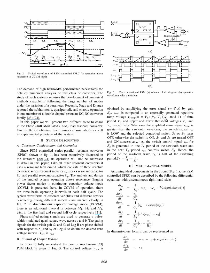
Fig. 2. Typical waveforms of PSM controlled SPRC for operation aboveresonance in CCVM mode
The demand of high bandwidth performance necessitates thedetailed numerical analysis of this class of converter. Thestudy of such systems requires the development of numericalmethods capable of following the large number of modesunder the variation of a parameter. Recently, Nagy and Drangareported the subharmonic, quasiperiodic and chaotic operationin one member of a double channel resonant DC-DC converterfamily [23],[24].
In this paper we will present two different route to chaosin the Phase Shift Modulated (PSM) load resonant converter.Our results are obtained from numerical simulations as wellas experimental prototype of the system.
II. SYSTEM DESCRIPTION
A. Converter Configuration and Operation
Since PSM controlled series-parallel resonant converter(SPRC) shown in fig. 1. has been extensively discussed inthe literature [20],[21] its operation will not be addressedin detail in this paper. Like all other resonant converters ituses a resonant tank circuit which consists of three reactiveelements: series resonant inductor Ls, series resonant capacitorCs, and parallel resonant capacitor Cp. The analysis and designof the studied system operating above resonance (laggingpower factor mode) in continuous capacitor voltage mode(CCVM) is presented here. In CCVM of operation, thereare three basic operating intervals in each half cycle. Thetypical waveforms of different variables and different devicesconducting during different intervals are marked clearly inFig. 2. In discontinuous capacitor voltage mode (DCVM),there is an additional interval in between M1, M2 and M4,M5, in the first half and second half cycle respectively [21].
Phase-shifted gating signals are used to generate a pulse-width-modulated quasi-square wave across a and b. The gatingsignals for the switch pair S2 and S2 of Leg B are phase shiftedwith respect to S1 and S1 of Leg A to obtain the desired zerovoltage interval Tsft in vab.
B. Control of Output Voltage
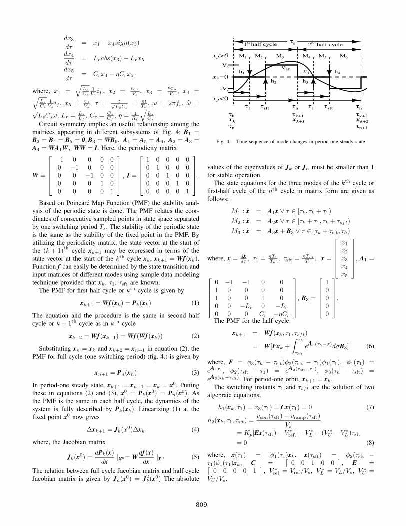
In order to fully understand the control mechanism [33]PSM block is given in Fig. 3. The control voltage vcon is
Q
Q
D
R
Svramp
vres
vcon
Q
Q
CLKD F/F
RS F/F
oo
+-
+-
+-- - -
Leg A
Leg B
DC
Comparator
vsc
(a)
CLK
vsc
vcon
vresvramp
Leg A
Leg B
(b)
Fig. 3. The conventional PSM (a) scheme block diagram (b) operationwaveforms with a transient
obtained by amplifying the error signal (v0-Vref ) by gainKp. vcon is compared to an externally generated repetitiveramp voltage vramp(t) = VL+(VU -VL)( t
Thmod 1) of time
period Th and upper and lower threshold voltages VU andVL respectively. Whenever the amplified error signal vcon isgreater than the sawtooth waveform, the switch signal vsc
is LOW and the selected controlled switch S2 or S2 turnsOFF. otherwise the switch is ON. S2 and S2 are turned OFFand ON successively, i.e., the switch control signal vsc forS2 is generated in one Th period of the sawtooth wave andin the next Th period vsc controls switch S2. Hence, theperiod of the sawtooth wave Th is half of the switchingperiod:Th = Ts
2 = 1
fs
.
III. MATHEMATICAL MODEL
Assuming ideal components in the circuit (Fig. 1.), the PSMcontrolled SPRC can be described by the following differentialequations with discontinuous right hand sides
diLdt
=1Ls
[−vCs− vCp
+ Vssign(sin(wt))]
dvCs
dt=
iLCs
dvCp
dt=
1Cp
[iL − ifsign(vCp)]
difdt
=1
Lf[abs(vCp
) − v0]
dv0
dt=
1Cf
[if − v0
RL]
In dimensionless form it can be represented as
dx1
dτ= −x1 − x3 + sign(sin(ωτ))
dx2
dτ= x1
808
dx3
dτ= x1 − x4sign(x3)
dx4
dτ= Lrabs(x3) − Lrx5
dx5
dτ= Crx4 − ηCrx5
where, x1 =√
Ls
Cs
1Vs
iL, x2 = vCs
Vs, x3 = vCp
Vs, x4 =√
Ls
Cs
1Vs
if , x5 = v0Vs
, τ = t√LsCs
= πtTh
, ω = 2πfs, ω =√
LsCsω, Lr = Ls
Lf, Cr = Cs
Cf, η = 1
RL
√Ls
Cs.
Circuit symmetry implies an useful relationship among thematrices appearing in different subsystems of Fig. 4: B1 =B2 = B4 = B5 = 0, B3 = WB6, A1 = A5 = A6, A2 = A3 =A4 = WA1W, WW = I. Here, the periodicity matrix
W =
⎡⎢⎢⎢⎢⎣
−1 0 0 0 00 −1 0 0 00 0 −1 0 00 0 0 1 00 0 0 0 1
⎤⎥⎥⎥⎥⎦ , I =
⎡⎢⎢⎢⎢⎣
1 0 0 0 00 1 0 0 00 0 1 0 00 0 0 1 00 0 0 0 1
⎤⎥⎥⎥⎥⎦ .
Based on Poincare Map Function (PMF) the stability anal-ysis of the periodic state is done. The PMF relates the coor-dinates of consecutive sampled points in state space separatedby one switching period Ts. The stability of the periodic stateis the same as the stability of the fixed point in the PMF. Byutilizing the periodicity matrix, the state vector at the start ofthe (k + 1)th cycle xk+1 may be expressed in terms of thestate vector at the start of the kth cycle xk, xk+1 = Wf(xk).Function f can easily be determined by the state transition andinput matrices of different modes using sample data modelingtechnique provided that xk, τ1, τsft are known.
The PMF for first half cycle or kth cycle is given by
xk+1 = Wf(xk) = Pk(xk) (1)
The equation and the procedure is the same in second halfcycle or k + 1th cycle as in kth cycle
xk+2 = Wf(xk+1) = Wf(Wf(xk)) (2)
Substituting xn = xk and xk+2 = xn+1 in equation (2), thePMF for full cycle (one switching period) (fig. 4.) is given by
xn+1 = Pn(xn) (3)
In period-one steady state, xk+1 = xn+1 = xk = x0. Puttingthese in equations (2) and (3), x0 = Pk(x0) = Pn(x0). Asthe PMF is the same in each half cycle, the dynamics of thesystem is fully described by Pk(xk). Linearizing (1) at thefixed point x0 now gives
Δxk+1 = Jk(x0)Δxk (4)
where, the Jacobian matrix
Jk(x0) =dPk(x)
dx|x0= W
df(x)dx
|x0 (5)
The relation between full cycle Jacobian matrix and half cycleJacobian matrix is given by Jn(x0) = J2
k(x0) The absolute
M1 M2 M3 M4 M5 M6
vab
τ1 τsft τh
τs
τn
τk+1τk
τh
τk+2
τn+1
τ1 τsft
x3x3=0
x3>0
x3<0
h2
h1
h3
h4
1st half cycle 2nd half cycle
xk xk+1 xk+2
Vs
-Vs
Fig. 4. Time sequence of mode changes in period-one steady state
values of the eigenvalues of Jk or Jn must be smaller than 1for stable operation.
The state equations for the three modes of the kth cycle orfirst-half cycle of the nth cycle in matrix form are given asfollows:
M1 : x = A1x ∨ τ ∈ [τk, τk + τ1)M2 : x = A2x ∨ τ ∈ [τk + τ1, τk + τsft)M3 : x = A3x + B3 ∨ τ ∈ [τk + τsft, τh)
where, x = dxdτ , τ1 = πT1
Th, τsft = πTsft
Th, x =
⎡⎢⎢⎢⎢⎣
x1
x2
x3
x4
x5
⎤⎥⎥⎥⎥⎦, A1 =
⎡⎢⎢⎢⎢⎣
0 −1 −1 0 01 0 0 0 01 0 0 1 00 0 −Lr 0 −Lr
0 0 0 Cr −ηCr
⎤⎥⎥⎥⎥⎦, B3 =
⎡⎢⎢⎢⎢⎣
10000
⎤⎥⎥⎥⎥⎦.
The PMF for the half cycle
xk+1 = Wf(xk, τ1, τsft)
= W[Fxk +∫ τh
τsft
eA3(τh−σ)dσB3] (6)
where, F = φ3(τh − τsft)φ2(τsft − τ1)φ1(τ1), φ1(τ1) =eA1τ1 , φ2(τsft − τ1) = eA2(τsft−τ1), φ3(τh − τsft) =eA3(τh−τsft). For period-one orbit, xk+1 = xk.
The switching instants τ1 and τsft are the solution of twoalgebraic equations,
h1(xk, τ1) = x3(τ1) = Cx(τ1) = 0 (7)
h2(xk, τ1, τsft) =vcon(τsft) − vramp(τsft)
Vs
= Kp[Ex(τsft) − V ∗ref ] − V ∗
L − (V ∗U − V ∗
L )τsft
= 0 (8)
where, x(τ1) = φ1(τ1)xk, x(τsft) = φ2(τsft −τ1)φ1(τ1)xk, C =
[0 0 1 0 0
], E =[
0 0 0 0 1], V ∗
ref = Vref/Vs, V ∗L = VL/Vs, V ∗
U =VU/Vs.
809
Since each mode has linear dynamics, the SPRC is apiecewise-linear system. On the other hand, the whole system,the PSM controlled SPRC becomes a nonlinear system, dueto the dependence of the mode change instants τ1 and τsft onthe state variables x3 and x5 respectively.
To obtain a linearized dynamic model from the half-cyclemodel, the fixed point corresponding to the nominal operatingcondition of the converter must first be found. Given thenominal source voltage and the nominal half switching periodτh, the fixed point x0 and two switching instants τ0
1 and τ0sft
satisfies (6), (7) and (8),
x0 = Wf(x0, τ01 , τ0
sft)h1(x0, τ0
1 ) = 0h2(x0, τ0
1 , τ0sft) = 0
This set of nonlinear equations can be solved numerically byNewton-Raphson’s method. After getting the fixed point(or theperiodic solution in continuous time) we can study the stabilityof the limit cycle by linearizing (6), (7) and (8).
Jk(x0) = W[∂f∂x
− ∂f∂p
(∂h∂p
)−1
(∂h∂x
)T
]|(x0, τ01 , τ0
sft) (9)
where, p =[
τ1 τsft
], h =
[h1 h2
]∂f∂x
= F
∂f∂τ1
= φ3(τh − τsft)φ2(τsft − τ1)[A1 − A2]φ1(τ1)xk
∂f∂τsft
= −φ3(τh − τsft)B3
∂h1
∂x= Cφ1(τ1)
∂h1
∂τ1= CA1φ1(τ1)xk
∂h2
∂x= −KpEφ2(τsft − τ1)φ1(τ1)
∂h2
∂τ1= −KpEφ2(τsft − τ1)[A1 − A2]φ1(τ1)xk
∂h2
∂τsft= −KpEA2x(τsft)[V ∗
U − V ∗L ]/τh
For the stable period-one orbit, the consideration of half-cycle dynamics is sufficient due to circuit symmetry [24].When the period-one orbit loses stability, i.e., beyond the firstinstability, a higher periodic stable orbit may occur; but thesymmetry between the half cycles will break, i.e., relation (5)does not hold. There may be another switching due to thepresence of the DCVM operation in some cycles:
h3 = x4 − abs(x1) = 0. (10)
IV. SIMULATION RESULTS
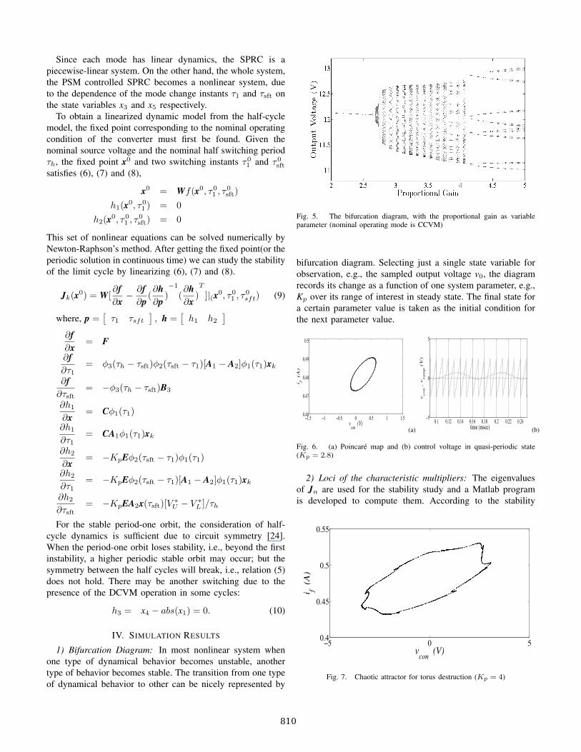
1) Bifurcation Diagram: In most nonlinear system whenone type of dynamical behavior becomes unstable, anothertype of behavior becomes stable. The transition from one typeof dynamical behavior to other can be nicely represented by
Fig. 5. The bifurcation diagram, with the proportional gain as variableparameter (nominal operating mode is CCVM)
bifurcation diagram. Selecting just a single state variable forobservation, e.g., the sampled output voltage v0, the diagramrecords its change as a function of one system parameter, e.g.,Kp over its range of interest in steady state. The final state fora certain parameter value is taken as the initial condition forthe next parameter value.
−1.5 −1 −0.5 0 0.5 1 1.50.46
0.47
0.48
0.49
0.5
vcon
(V)
i f
(A
)
(a)0.1 0.12 0.14 0.16 0.18 0.2 0.22 0.24
−5
0
5
time (msec)v
con ,
vram
p (
V)
(b)
Fig. 6. (a) Poincare map and (b) control voltage in quasi-periodic state(Kp = 2.8)
2) Loci of the characteristic multipliers: The eigenvaluesof Jn are used for the stability study and a Matlab programis developed to compute them. According to the stability
−5 0 50.4
0.45
0.5
0.55
vcon
(V)
i f (A
)
Fig. 7. Chaotic attractor for torus destruction (Kp = 4)
810
condition, as long as the characteristic multipliers lie insidethe unit circle, the periodic steady state solution is asymptoti-cally stable. When a complex-conjugate pair of characteristicmultipliers gets outside the unit circle the periodic solutionloses stability by Hopf bifurcation.
The values of parameters used in this study are: Ls =150 μH, Cs = Cp = 0.1 μF, Lf = 3000 μH, Cf = 0.47μF,Vref =12 V, VL = −2.5 V, VU = 2.5 V, Vs = 15 V,fs = 50 kHz, RL = 25 Ω.
At Kp = 2.64, the eigenvalues are −0.1066±0.9944(modulus�1) , 0.4215, 0.1169, 0.03295.
−5 0 50.4
0.45
0.5
0.55
vcon
(V)
i f
(A
)
(a)
−5 0 50.4
0.45
0.5
0.55
vcon
(V)
i f
(A
)
(b)
Fig. 8. Poincare map for (a) period-4 (Kp = 4.15) and (b) period-8 (Kp =4.3)
0.1 0.12 0.14 0.16 0.18 0.2 0.22−5
0
5
time (msec)
vcon , v
ram
p (
V)
(a)
0.1 0.15 0.2 0.25 0.3 0.35−5
0
5
time (msec)
vcon , v
ram
p (
V)
(b)
Fig. 9. Control voltage for (a) period-4 (Kp = 4.15) and (b) period-8(Kp = 4.3)
3) Quasi-periodic route to chaos: When the periodic be-havior undergoes the Hopf bifurcation, quasi-periodic behavior
−5 0 50.4
0.45
0.5
0.55
vcon
(V)
i f (A
)
Fig. 10. Eight-piece chaotic attractor attractor at (Kp = 4.8)
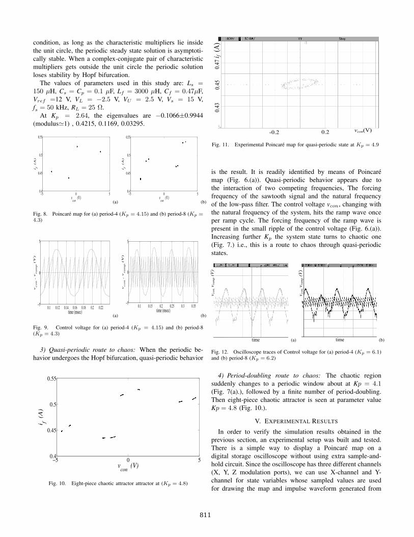
Fig. 11. Experimental Poincare map for quasi-periodic state at Kp = 4.9
is the result. It is readily identified by means of Poincaremap (Fig. 6.(a)). Quasi-periodic behavior appears due tothe interaction of two competing frequencies, The forcingfrequency of the sawtooth signal and the natural frequencyof the low-pass filter. The control voltage vcon, changing withthe natural frequency of the system, hits the ramp wave onceper ramp cycle. The forcing frequency of the ramp wave ispresent in the small ripple of the control voltage (Fig. 6.(a)).Increasing further Kp the system state turns to chaotic one(Fig. 7.) i.e., this is a route to chaos through quasi-periodicstates.
(a) (b)
Fig. 12. Oscilloscope traces of Control voltage for (a) period-4 (Kp = 6.1)and (b) period-8 (Kp = 6.2)
4) Period-doubling route to chaos: The chaotic regionsuddenly changes to a periodic window about at Kp = 4.1(Fig. 7(a).), followed by a finite number of period-doubling.Then eight-piece chaotic attractor is seen at parameter valueKp = 4.8 (Fig. 10.).
V. EXPERIMENTAL RESULTS
In order to verify the simulation results obtained in theprevious section, an experimental setup was built and tested.There is a simple way to display a Poincare map on adigital storage oscilloscope without using extra sample-and-hold circuit. Since the oscilloscope has three different channels(X, Y, Z modulation ports), we can use X-channel and Y-channel for state variables whose sampled values are usedfor drawing the map and impulse waveform generated from
811
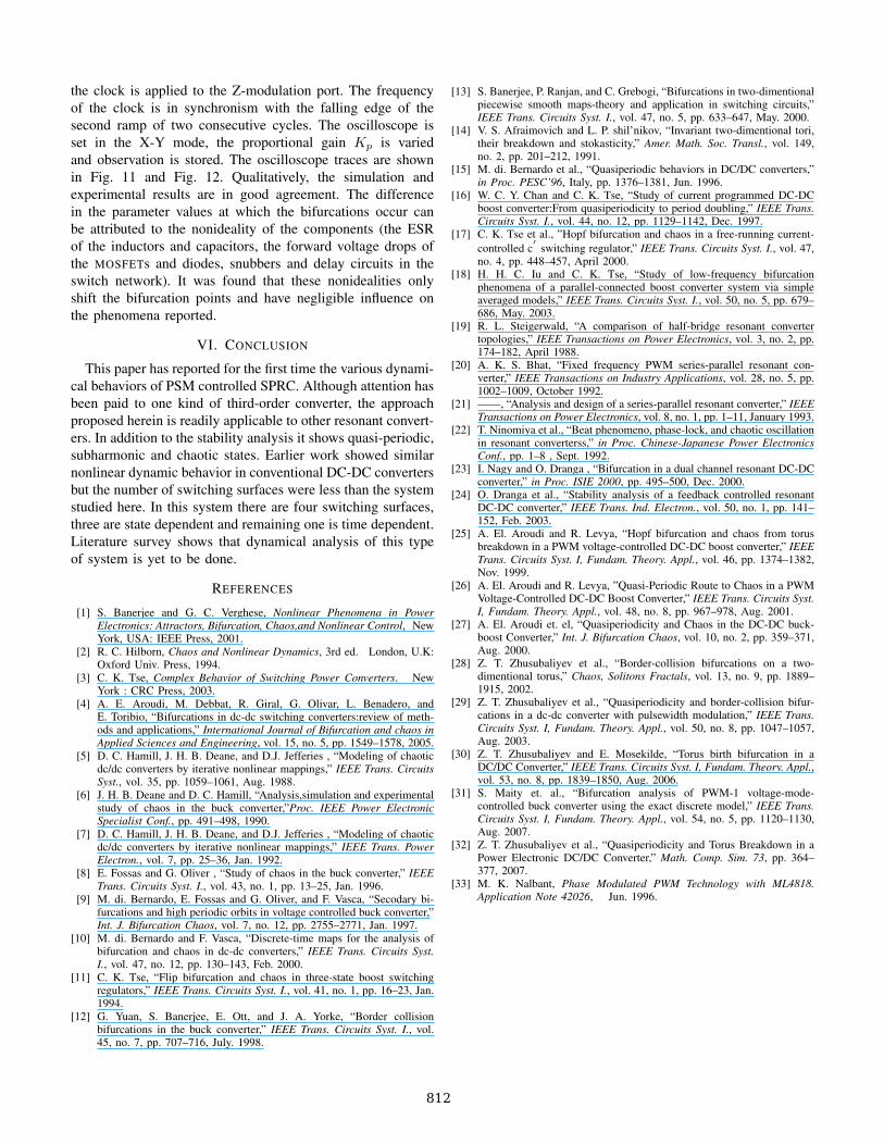
the clock is applied to the Z-modulation port. The frequencyof the clock is in synchronism with the falling edge of thesecond ramp of two consecutive cycles. The oscilloscope isset in the X-Y mode, the proportional gain Kp is variedand observation is stored. The oscilloscope traces are shownin Fig. 11 and Fig. 12. Qualitatively, the simulation andexperimental results are in good agreement. The differencein the parameter values at which the bifurcations occur canbe attributed to the nonideality of the components (the ESRof the inductors and capacitors, the forward voltage drops ofthe MOSFETs and diodes, snubbers and delay circuits in theswitch network). It was found that these nonidealities onlyshift the bifurcation points and have negligible influence onthe phenomena reported.
VI. CONCLUSION
This paper has reported for the first time the various dynami-cal behaviors of PSM controlled SPRC. Although attention hasbeen paid to one kind of third-order converter, the approachproposed herein is readily applicable to other resonant convert-ers. In addition to the stability analysis it shows quasi-periodic,subharmonic and chaotic states. Earlier work showed similarnonlinear dynamic behavior in conventional DC-DC convertersbut the number of switching surfaces were less than the systemstudied here. In this system there are four switching surfaces,three are state dependent and remaining one is time dependent.Literature survey shows that dynamical analysis of this typeof system is yet to be done.
REFERENCES
[1] S. Banerjee and G. C. Verghese, Nonlinear Phenomena in PowerElectronics: Attractors, Bifurcation, Chaos,and Nonlinear Control, NewYork, USA: IEEE Press, 2001.
[2] R. C. Hilborn, Chaos and Nonlinear Dynamics, 3rd ed. London, U.K:Oxford Univ. Press, 1994.
[3] C. K. Tse, Complex Behavior of Switching Power Converters. NewYork : CRC Press, 2003.
[4] A. E. Aroudi, M. Debbat, R. Giral, G. Olivar, L. Benadero, andE. Toribio, “Bifurcations in dc-dc switching converters:review of meth-ods and applications,” International Journal of Bifurcation and chaos inApplied Sciences and Engineering, vol. 15, no. 5, pp. 1549–1578, 2005.
[5] D. C. Hamill, J. H. B. Deane, and D.J. Jefferies , “Modeling of chaoticdc/dc converters by iterative nonlinear mappings,” IEEE Trans. CircuitsSyst., vol. 35, pp. 1059–1061, Aug. 1988.
[6] J. H. B. Deane and D. C. Hamill, “Analysis,simulation and experimentalstudy of chaos in the buck converter,”Proc. IEEE Power ElectronicSpecialist Conf., pp. 491–498, 1990.
[7] D. C. Hamill, J. H. B. Deane, and D.J. Jefferies , “Modeling of chaoticdc/dc converters by iterative nonlinear mappings,” IEEE Trans. PowerElectron., vol. 7, pp. 25–36, Jan. 1992.
[8] E. Fossas and G. Oliver , “Study of chaos in the buck converter,” IEEETrans. Circuits Syst. I., vol. 43, no. 1, pp. 13–25, Jan. 1996.
[9] M. di. Bernardo, E. Fossas and G. Oliver, and F. Vasca, “Secodary bi-furcations and high periodic orbits in voltage controlled buck converter,”Int. J. Bifurcation Chaos, vol. 7, no. 12, pp. 2755–2771, Jan. 1997.
[10] M. di. Bernardo and F. Vasca, “Discrete-time maps for the analysis ofbifurcation and chaos in dc-dc converters,” IEEE Trans. Circuits Syst.I., vol. 47, no. 12, pp. 130–143, Feb. 2000.
[11] C. K. Tse, “Flip bifurcation and chaos in three-state boost switchingregulators,” IEEE Trans. Circuits Syst. I., vol. 41, no. 1, pp. 16–23, Jan.1994.
[12] G. Yuan, S. Banerjee, E. Ott, and J. A. Yorke, “Border collisionbifurcations in the buck converter,” IEEE Trans. Circuits Syst. I., vol.45, no. 7, pp. 707–716, July. 1998.
[13] S. Banerjee, P. Ranjan, and C. Grebogi, “Bifurcations in two-dimentionalpiecewise smooth maps-theory and application in switching circuits,”IEEE Trans. Circuits Syst. I., vol. 47, no. 5, pp. 633–647, May. 2000.
[14] V. S. Afraimovich and L. P. shil’nikov, “Invariant two-dimentional tori,their breakdown and stokasticity,” Amer. Math. Soc. Transl., vol. 149,no. 2, pp. 201–212, 1991.
[15] M. di. Bernardo et al., “Quasiperiodic behaviors in DC/DC converters,”in Proc. PESC’96, Italy, pp. 1376–1381, Jun. 1996.
[16] W. C. Y. Chan and C. K. Tse, “Study of current programmed DC-DCboost converter:From quasiperiodicity to period doubling,” IEEE Trans.Circuits Syst. I., vol. 44, no. 12, pp. 1129–1142, Dec. 1997.
[17] C. K. Tse et al., ”Hopf bifurcation and chaos in a free-running current-controlled c
′switching regulator,” IEEE Trans. Circuits Syst. I., vol. 47,
no. 4, pp. 448–457, April 2000.[18] H. H. C. Iu and C. K. Tse, “Study of low-frequency bifurcation
phenomena of a parallel-connected boost converter system via simpleaveraged models,” IEEE Trans. Circuits Syst. I., vol. 50, no. 5, pp. 679–686, May. 2003.
[19] R. L. Steigerwald, “A comparison of half-bridge resonant convertertopologies,” IEEE Transactions on Power Electronics, vol. 3, no. 2, pp.174–182, April 1988.
[20] A. K. S. Bhat, “Fixed frequency PWM series-parallel resonant con-verter,” IEEE Transactions on Industry Applications, vol. 28, no. 5, pp.1002–1009, October 1992.
[21] ——, “Analysis and design of a series-parallel resonant converter,” IEEETransactions on Power Electronics, vol. 8, no. 1, pp. 1–11, January 1993.
[22] T. Ninomiya et al., “Beat phenomeno, phase-lock, and chaotic oscillationin resonant converterss,” in Proc. Chinese-Japanese Power ElectronicsConf., pp. 1–8 , Sept. 1992.
[23] I. Nagy and O. Dranga , “Bifurcation in a dual channel resonant DC-DCconverter,” in Proc. ISIE 2000, pp. 495–500, Dec. 2000.
[24] O. Dranga et al., “Stability analysis of a feedback controlled resonantDC-DC converter,” IEEE Trans. Ind. Electron., vol. 50, no. 1, pp. 141–152, Feb. 2003.
[25] A. El. Aroudi and R. Levya, “Hopf bifurcation and chaos from torusbreakdown in a PWM voltage-controlled DC-DC boost converter,” IEEETrans. Circuits Syst. I, Fundam. Theory. Appl., vol. 46, pp. 1374–1382,Nov. 1999.
[26] A. El. Aroudi and R. Levya, ”Quasi-Periodic Route to Chaos in a PWMVoltage-Controlled DC-DC Boost Converter,” IEEE Trans. Circuits Syst.I, Fundam. Theory. Appl., vol. 48, no. 8, pp. 967–978, Aug. 2001.
[27] A. El. Aroudi et. el, “Quasiperiodicity and Chaos in the DC-DC buck-boost Converter,” Int. J. Bifurcation Chaos, vol. 10, no. 2, pp. 359–371,Aug. 2000.
[28] Z. T. Zhusubaliyev et al., “Border-collision bifurcations on a two-dimentional torus,” Chaos, Solitons Fractals, vol. 13, no. 9, pp. 1889–1915, 2002.
[29] Z. T. Zhusubaliyev et al., “Quasiperiodicity and border-collision bifur-cations in a dc-dc converter with pulsewidth modulation,” IEEE Trans.Circuits Syst. I, Fundam. Theory. Appl., vol. 50, no. 8, pp. 1047–1057,Aug. 2003.
[30] Z. T. Zhusubaliyev and E. Mosekilde, “Torus birth bifurcation in aDC/DC Converter,” IEEE Trans. Circuits Syst. I, Fundam. Theory. Appl.,vol. 53, no. 8, pp. 1839–1850, Aug. 2006.
[31] S. Maity et. al., “Bifurcation analysis of PWM-1 voltage-mode-controlled buck converter using the exact discrete model,” IEEE Trans.Circuits Syst. I, Fundam. Theory. Appl., vol. 54, no. 5, pp. 1120–1130,Aug. 2007.
[32] Z. T. Zhusubaliyev et al., “Quasiperiodicity and Torus Breakdown in aPower Electronic DC/DC Converter,” Math. Comp. Sim. 73, pp. 364–377, 2007.
[33] M. K. Nalbant, Phase Modulated PWM Technology with ML4818.Application Note 42026, Jun. 1996.
812
Related Documents