NANO EXPRESS Open Access Quasi-classical modeling of molecular quantum-dot cellular automata multidriver gates Ehsan Rahimi * and Shahram Mohammad Nejad Abstract Molecular quantum-dot cellular automata (mQCA) has received considerable attention in nanoscience. Unlike the current-based molecular switches, where the digital data is represented by the on/off states of the switches, in mQCA devices, binary information is encoded in charge configuration within molecular redox centers. The mQCA paradigm allows high device density and ultra-low power consumption. Digital mQCA gates are the building blocks of circuits in this paradigm. Design and analysis of these gates require quantum chemical calculations, which are demanding in computer time and memory. Therefore, developing simple models to probe mQCA gates is of paramount importance. We derive a semi-classical model to study the steady-state output polarization of mQCA multidriver gates, directly from the two-state approximation in electron transfer theory. The accuracy and validity of this model are analyzed using full quantum chemistry calculations. A complete set of logic gates, including inverters and minority voters, are implemented to provide an appropriate test bench in the two-dot mQCA regime. We also briefly discuss how the QCADesigner tool could find its application in simulation of mQCA devices. Keywords: Electron transfer reactions, Molecular electronics, Molecular gates, Molecular quantum-dots, Quantum cellular automata Background Recent advances in molecular electronics on one hand and the limitations of conventional semiconductor devices, on the other hand, have driven a surge of activ- ities towards the realization of molecular devices, cir- cuits, and systems. Achieving the ultimate diminution in size, power consumption, and delay of electronic devices and systems has always been a challenging en- deavor of scientists and designers in this field. Due to the prospect of size reduction in electronics offered by molecular-level control of properties, molecular elec- tronics provides means to extend the Moore's law be- yond the foreseen limits of small-scale conventional silicon integrated circuits. The small size of molecules allows high device density in the range of 10 11 to 10 12 devices/cm 2 [1]. Besides, the chemical self-assembly capacity in manufacturing molecular devices provides many advantages to conventional semiconductor manu- facturing technology, including lower manufacturing cost and uniform device reproducibility. Molecular elec- tronics endeavors to use the nonlinear current–voltage characteristics of individual molecules or molecular as- semblies as active devices (diodes, transistors, etc.) in electronic circuits. However, the power consumption of molecular current switches at very high frequencies is still a drawback [2]. The π-σ-π mixed-valence type molecules, which provide double-well potentials for electrons, have been proposed and studied by Aviram towards the synthesis of memory, logic, and amplifica- tion [3]. Lent proposed using molecules in representing binary information within the molecular quantum-dot cellular automata (mQCA) paradigm [1,4]. Molecular QCA provides an alternative approach to represent and process data, where binary representation lies in the charge configuration within molecules rather than in the on/ off states of current switches. A cell in the mQCA model consists of a number of molecular quantum dots (or redox centers) and a few electrons. The electrons tend to occupy antipodal sites as a result of Coulomb repulsion. The Columbic interactions cause electrons to tunnel from one redox center to another in a cell, but not between cells. Thus, it is likely that no current * Correspondence: [email protected] Nanoptronics Research Center, School of Electrical and Electronic Engineering, Iran University of Science and Technology, Tehran 16844, Iran © 2012 Rahimi and Mohammad Nejad; licensee Springer. This is an Open Access article distributed under the terms of the Creative Commons Attribution License (http://creativecommons.org/licenses/by/2.0), which permits unrestricted use, distribution, and reproduction in any medium, provided the original work is properly cited. Rahimi and Nejad Nanoscale Research Letters 2012, 7:274 http://www.nanoscalereslett.com/content/7/1/274

Welcome message from author
This document is posted to help you gain knowledge. Please leave a comment to let me know what you think about it! Share it to your friends and learn new things together.
Transcript

Rahimi and Nejad Nanoscale Research Letters 2012, 7:274http://www.nanoscalereslett.com/content/7/1/274
NANO EXPRESS Open Access
Quasi-classical modeling of molecularquantum-dot cellular automata multidriver gatesEhsan Rahimi* and Shahram Mohammad Nejad
Abstract
Molecular quantum-dot cellular automata (mQCA) has received considerable attention in nanoscience. Unlike thecurrent-based molecular switches, where the digital data is represented by the on/off states of the switches, inmQCA devices, binary information is encoded in charge configuration within molecular redox centers. The mQCAparadigm allows high device density and ultra-low power consumption. Digital mQCA gates are the building blocksof circuits in this paradigm. Design and analysis of these gates require quantum chemical calculations, which aredemanding in computer time and memory. Therefore, developing simple models to probe mQCA gates is ofparamount importance. We derive a semi-classical model to study the steady-state output polarization of mQCAmultidriver gates, directly from the two-state approximation in electron transfer theory. The accuracy and validity ofthis model are analyzed using full quantum chemistry calculations. A complete set of logic gates, includinginverters and minority voters, are implemented to provide an appropriate test bench in the two-dot mQCA regime.We also briefly discuss how the QCADesigner tool could find its application in simulation of mQCA devices.
Keywords: Electron transfer reactions, Molecular electronics, Molecular gates, Molecular quantum-dots, Quantumcellular automata
BackgroundRecent advances in molecular electronics on one handand the limitations of conventional semiconductordevices, on the other hand, have driven a surge of activ-ities towards the realization of molecular devices, cir-cuits, and systems. Achieving the ultimate diminutionin size, power consumption, and delay of electronicdevices and systems has always been a challenging en-deavor of scientists and designers in this field. Due tothe prospect of size reduction in electronics offered bymolecular-level control of properties, molecular elec-tronics provides means to extend the Moore's law be-yond the foreseen limits of small-scale conventionalsilicon integrated circuits. The small size of moleculesallows high device density in the range of 1011 to 1012
devices/cm2 [1]. Besides, the chemical self-assemblycapacity in manufacturing molecular devices providesmany advantages to conventional semiconductor manu-facturing technology, including lower manufacturing
* Correspondence: [email protected] Research Center, School of Electrical and ElectronicEngineering, Iran University of Science and Technology, Tehran 16844, Iran
© 2012 Rahimi and Mohammad Nejad; licenseCreative Commons Attribution License (http://cdistribution, and reproduction in any medium,
cost and uniform device reproducibility. Molecular elec-tronics endeavors to use the nonlinear current–voltagecharacteristics of individual molecules or molecular as-semblies as active devices (diodes, transistors, etc.) inelectronic circuits. However, the power consumption ofmolecular current switches at very high frequencies isstill a drawback [2]. The π-σ-π mixed-valence typemolecules, which provide double-well potentials forelectrons, have been proposed and studied by Aviramtowards the synthesis of memory, logic, and amplifica-tion [3]. Lent proposed using molecules in representingbinary information within the molecular quantum-dotcellular automata (mQCA) paradigm [1,4]. MolecularQCA provides an alternative approach to represent andprocess data, where binary representation lies in the chargeconfiguration within molecules rather than in the on/off states of current switches. A cell in the mQCAmodel consists of a number of molecular quantum dots(or redox centers) and a few electrons. The electronstend to occupy antipodal sites as a result of Coulombrepulsion. The Columbic interactions cause electrons totunnel from one redox center to another in a cell, butnot between cells. Thus, it is likely that no current
e Springer. This is an Open Access article distributed under the terms of thereativecommons.org/licenses/by/2.0), which permits unrestricted use,provided the original work is properly cited.
Rahimi and Nejad Nanoscale Research Letters 2012, 7:274 Page 2 of 12http://www.nanoscalereslett.com/content/7/1/274
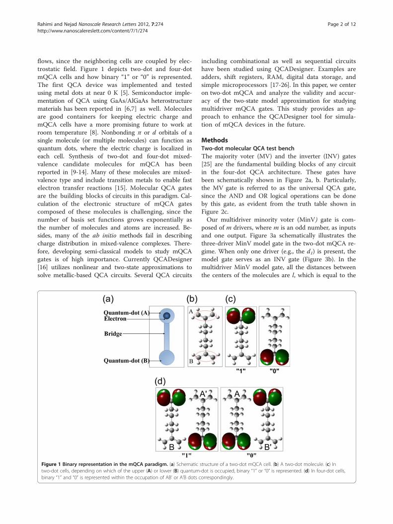
flows, since the neighboring cells are coupled by elec-trostatic field. Figure 1 depicts two-dot and four-dotmQCA cells and how binary “1” or “0” is represented.The first QCA device was implemented and testedusing metal dots at near 0 K [5]. Semiconductor imple-mentation of QCA using GaAs/AlGaAs heterostructurematerials has been reported in [6,7] as well. Moleculesare good containers for keeping electric charge andmQCA cells have a more promising future to work atroom temperature [8]. Nonbonding π or d orbitals of asingle molecule (or multiple molecules) can function asquantum dots, where the electric charge is localized ineach cell. Synthesis of two-dot and four-dot mixed-valence candidate molecules for mQCA has beenreported in [9-14]. Many of these molecules are mixed-valence type and include transition metals to enable fastelectron transfer reactions [15]. Molecular QCA gatesare the building blocks of circuits in this paradigm. Cal-culation of the electronic structure of mQCA gatescomposed of these molecules is challenging, since thenumber of basis set functions grows exponentially asthe number of molecules and atoms are increased. Be-sides, many of the ab initio methods fail in describingcharge distribution in mixed-valence complexes. There-fore, developing semi-classical models to study mQCAgates is of high importance. Currently QCADesigner[16] utilizes nonlinear and two-state approximations tosolve metallic-based QCA circuits. Several QCA circuits
Figure 1 Binary representation in the mQCA paradigm. (a) Schematictwo-dot cells, depending on which of the upper (A) or lower (B) quantumbinary “1” and “0” is represented within the occupation of AB’ or A’B dots c
including combinational as well as sequential circuitshave been studied using QCADesigner. Examples areadders, shift registers, RAM, digital data storage, andsimple microprocessors [17-26]. In this paper, we centeron two-dot mQCA and analyze the validity and accur-acy of the two-state model approximation for studyingmultidriver mQCA gates. This study provides an ap-proach to enhance the QCADesigner tool for simula-tion of mQCA devices in the future.
MethodsTwo-dot molecular QCA test benchThe majority voter (MV) and the inverter (INV) gates[25] are the fundamental building blocks of any circuitin the four-dot QCA architecture. These gates havebeen schematically shown in Figure 2a, b. Particularly,the MV gate is referred to as the universal QCA gate,since the AND and OR logical operations can be doneby this gate, as evident from the truth table shown inFigure 2c.Our multidriver minority voter (MinV) gate is com-
posed of m drivers, where m is an odd number, as inputsand one output. Figure 3a schematically illustrates thethree-driver MinV model gate in the two-dot mQCA re-gime. When only one driver (e.g., the d1) is present, themodel gate serves as an INV gate (Figure 3b). In themultidriver MinV model gate, all the distances betweenthe centers of the molecules are l, which is equal to the
structure of a two-dot mQCA cell. (b) A two-dot molecule. (c) In-dot is occupied, binary “1” or “0” is represented. (d) In four-dot cells,orrespondingly.

Figure 2 Four-dot QCA gates. (a) The universal MV gate. The majority of the three fixed inputs, which is “0” in this figure, appears at the outputas a result of Coulombic interactions and minimum energetics. (b) The inverter gate. (c) Truth table of the MV gate. When d3 = ”0”, the MV gateperforms AND logical operations on d1 and d2, and when d3 = ”1” the MV gate functions as a two-input OR gate [25].
Rahimi and Nejad Nanoscale Research Letters 2012, 7:274 Page 3 of 12http://www.nanoscalereslett.com/content/7/1/274
distance between the middle of upper and lower π-bonds as shown in Figure 3c. The inputs of the gates arekept fixed, while the output cells switch to their stablestates. To this end, two point charges q and 1-q sepa-rated by distance l are used to mimic each input asdepicted in Figure 3c.The MinV gate is an alternative to the MV gate in
the four-dot QCA, where the output is inverted.Compared to MV and INV gates in the four-dotarchitecture, which require 16 and 28 quantum-dotscorrespondingly, the MinV and INV gates require only8 and 4 quantum-dots in the two-dot mQCA regime.Consequently, these gates provide a small two-dotmQCA test bench, which make high level quantumchemical calculations feasible. The MinV gate can per-form NAND and NOR logical operations, as shownin Figure 3d, and provides a functionally completelogic set to implement any logic function in the two-dotmQCA framework. Additionally, it is possible to im-plement multi-input (or multidriver) MinV gates, whichin turn decrease the total number of gates requiredto implement a logic circuit. It is important to notethat since the MinV gate is not a planar gate, circuitsimplemented in the two-dot mQCA regime are notplanar circuits. We highlight that the practical QCAcircuits require clocked-control cells and clockingschemes [21,27-29], which are not addressed in thispaper.
Two-state model for molecular QCA gatesThe charge configuration in a QCA cell is quantified bythe so called ‘polarization’, and is defined as [30]
P ¼ qA þ qB′ð Þ � qB þ qA′ð ÞqA þ qB þ qA′ þ qB′
ð1Þ
where qA, qB, qA′ and qB′ are the charges localized at fourquantum dots labeled in Figure 1. For two-dot mQCAcells, the polarization is given by the charges qA and qB atthe corresponding redox centers in Equation 1. Thepolarization of a QCA cell varies between −1 and 1, whilenegative and positive polarizations represent binary “0”and “1”, respectively. In two-dot mQCA cells, the nor-malized dipole moment of the used two-dot molecule isalso identical to the polarization, which is given by
P ¼ μαl=2
ð2Þ
where μα denotes the component of the molecular dipolemoment that is parallel to the bridge direction, and theorigin is in the middle of the bridge. The dipole momentof an mQCA cell can be obtained through full quantumchemical calculations. An important parameter of a QCAdevice is the Kink energy (Ek), which is the required en-ergy to excite the system from the ground state to thefirst excited state. To distinguish a bit value from thethermal environment, Ek must be greater than kBT [31],

Figure 3 Two-dot QCA gates. (a) Structure of the three-input MinV gate. This gate is composed of three fixed inputs (d1, d2, and d3) and atwo-dot molecule (AB) as output. The minority of the three fixed inputs, which is “0” in this figure, appears at the output. (b) When there is onlyone input, the MinV gate functions as an inverter gate. (c) Two point charges q and 1-q separated by distance l, which is the distance betweenthe middle of upper and lower π-bonds, are used to mimic a fixed input. (d) Truth table of the MinV gate. When d3 = ”0”, the MinV gateperforms NAND logical operation on d1 and d2, and when d3 = ”1” the MinV gate functions as a two-input NOR gate.
Rahimi and Nejad Nanoscale Research Letters 2012, 7:274 Page 4 of 12http://www.nanoscalereslett.com/content/7/1/274
where T is the operation temperature in Kelvin, and kB isthe Boltzmann's constant. The Ek represents the energycost of cells i and j having opposite polarizations. That is,the electrostatic interaction between all the charges incells i and j is calculated by [16]
Ei;j ¼Xi;j
14πE0Er
qiqjri � rj�� �� ð3Þ
where E0 is the permittivity of free space, and Er is therelative permittivity of the material system. The Kink en-ergy is then given by [16]
Ek ¼ E′i;j � Ei;j ð4Þ
where E′i,j and Ei,j denote the electrostatic energy of cellsi and j having opposite and same polarizationscorrespondingly.Tougaw and Lent have used a simple Hamiltonian of
the extended-Hubbard type to describe the dynamic be-havior of four-dot metallic-based QCA nanodevices [32].
Although this Hamiltonian describes the dynamics ofthe coherent system composed of arrays of four-dotQCA cells elegantly in theory, it is only possible tomodel the small systems employing this scheme, sincethe total required number of direct-product basis setsgrows exponentially with the number of cells. In otherwords, an array with N number of four-dot cells and Bnumber of basis sets in each cell requires the total num-ber of direct-product basis sets as [32]
nbasis ¼ BN ð5ÞBy reducing the number of basis sets for each cell and
picking up the two orthogonal ones, the Hamiltonian ofa four-dot QCA wire can be mapped to Ising model as[32,33]
H ¼ �γXN
i¼1σx ið Þ � Ek
2
XN�1
i¼1σz ið Þσz iþ 1ð Þ ð6Þ
where Ek is the kink energy of four-dot cells, γ is thetunneling energy, and σx and σz are Pauli spin matrices.

Rahimi and Nejad Nanoscale Research Letters 2012, 7:274 Page 5 of 12http://www.nanoscalereslett.com/content/7/1/274
In semiconductor and metal-dot QCA, the tunnelingbarriers of the cells are connected to electrodes, andtheir heights are controlled externally by voltage sources[33]. The steady-state polarization of any cell, j in ablock of cells, can be obtained as a solution to theHartree-Fock intercellular approximation. This approxi-mation decouples the line of N cells into N single cellsubsystems and assumes that the cells are only coupledthrough expectation values of polarizations. The conse-quent solution is [33],
Pj ¼Ek
2γ�Pjffiffiffiffiffiffiffiffiffiffiffiffiffiffiffiffiffiffiffiffiffiffiffiffiffiffiffi
1þ Ek2γ
�Pj
� �2s ð7Þ
where P—j is the sum of the polarizations of the neighbor-
ing four-dot QCA cells. Equation 7 is currently used inthe nonlinear and two-state simulation engine of QCA-Designer to solve the metallic-based QCA circuits. It isimportant to note that mQCA utilizes non-abrupt clock-ing to reduce the probability of Kink, the property that isnot currently present in the QCADesigner as it is basedon metallic QCA. In mQCA, the tunneling barriers canbe controlled by external electric field [27]. It is demand-ing to enhance the tool to be able to simulate mQCA cir-cuits. As a primary step towards this end, we presenthow a similar equation to (7) can be derived directlyfrom the two-state approximation in electron transfertheory [34,35] for two-dot mQCA. We then discuss howthese approximations affect the results compared tothose obtained from full quantum chemistry calculations.Equation 8 describes the electron transfer (ET) process
in a two-dot mQCA cell, where the two redox centers, Aand B, are linked through an intervening bridge, I.
A� � I � B , A� I � B� ð8Þ
The electronic coupling between the redox centers,which is time independent, is an important factor inthe ET process. Within the two-state approximation,the Landau-Zener model [36,37] for avoided crossingof energy surfaces may be applied, where the two dia-batic states “1” and “0” denoted by ψa and ψb, and withenergies Haa and Hbb interact. The ground state ψ1 andthe first excited state of a QCA cell, ψ2, can be relatedto the diabatic states ψa and ψb by a unitary transform-ation [34]
ψ1 ¼ cosη ψa � sinη ψb ð9Þψ2 ¼ sinη ψa þ cosη ψb ð10Þ
In Equations 9 and 10, ψ1 and ψ2 are orthonormal,whereas ψa and ψb are not orthogonal in general. The
correspondence between diabatic and adiabatic two-statemodels arises from the secular determinant (Sab =<ψa|ψb> is neglected) [38]
Haa � E Hab
Hab Hbb � E
�������� ¼ 0 ð11Þ
where E is the adiabatic energy eigenvalue. The η inEquations 9 and 10 satisfies [38]
tan2η ¼ 2Hab= Haa � Hbbð Þ ð12Þ
The energy difference between the two diabatic statesin the output cell of the MinV gate can be approximatedby calculating the difference between the electrostaticenergies of the gate for the two output configurations,where the unit charge is localized at sites A and B cor-respondingly. Using Equation 3, for the “1” and “0” out-put states (Figure 3a), we obtain
Haa � Hbb ¼ 14πE0
� q1 þ q2 þ q3ð Þe2l
þ 3� q1 þ q2 þ q3ð Þð Þe2ffiffiffi2
pl
� �
� 14πE0
q1 þ q2 þ q3ð Þe2ffiffiffi2
pl
þ 3� q1 þ q2 þ q3ð Þð Þe2l
� �ð13Þ
Inserting Equation 13 into Equation 12 we have
cot2η ¼ 12Hab
� �e2
4πE0l
� �2� ffiffiffi
2p
2
� �� 2 q1 þ q2 þ q3ð Þ � 3½ � ð14Þ
The Kink energy of two-dot cells can be calculatedfrom Equation 3 and 4 for two neighboring cells as
Ek ¼ �e2
4πE0l2� ffiffiffi
2p
2
� �ð15Þ
and for each driver, the polarization is defined usingEquation 1
Pdi ¼qie� 1� qið Þeqieþ 1� qið Þe ¼ 2qi � 1 ; i ¼ 1;2;3 ð16Þ
Thus, Equation 14 can be rewritten in terms of the Kinkenergy and the input polarizations
cot2η ¼ �Ek
2Hab
X3i¼1
Pdi ð17Þ

Rahimi and Nejad Nanoscale Research Letters 2012, 7:274 Page 6 of 12http://www.nanoscalereslett.com/content/7/1/274
And finally, using Equation 1 and the transformationcoefficients in Equations 9 and 10, the outputpolarization of the MinV gate is obtained
Po ¼ þeð Þ cos2η� þeð Þ sin2ηþeð Þ cos2ηþ þeð Þ sin2η ¼ cos2η
¼ � cot2ηffiffiffiffiffiffiffiffiffiffiffiffiffiffiffiffiffiffiffiffiffiffiffi1þ cot22η
p ð18Þ
Inserting Equation 17 into Equation 18, we can findthe polarization of the output cell of the MinV gate interms of the polarizations of the inputs straightfor-wardly as
Po Pd1 ; Pd2 ; Pd3ð Þ ¼
Ek
2Hab
X3i¼1
Pdiffiffiffiffiffiffiffiffiffiffiffiffiffiffiffiffiffiffiffiffiffiffiffiffiffiffiffiffiffiffiffiffiffiffiffiffiffiffiffiffiffiffiffiffiffiffiffiffi1þ EK
2Hab
� �2 P3i¼1
Pdi
� �2s ð19Þ
Equation 19 in two-dot mQCA is analogous to Equa-tion 7 in four-dot metal-based QCA, where the tunnel-ing energy γ appears as electronic coupling of redoxcenters (Hab) in Equation 19. They also imply
Po d1; d2; d3ð Þ ¼ Po d1 þ d2 þ d3ð Þ ð20ÞThe additivity relation in Equation 20 originates from
the additivity of electrostatic potential energy in Equa-tion 13 for diabatic states.Multidriver MinV gates help reduce the number of
needed gates for implementation of a logic circuit. Simi-larly, for an m-input MinV gate, we obtain
Po Pd1 ; Pd2 ; . . . ;Pdmð Þ ¼ PoXmi¼1
Pdi
!
¼
Ek
2Hab
Xmi¼1
Pdiffiffiffiffiffiffiffiffiffiffiffiffiffiffiffiffiffiffiffiffiffiffiffiffiffiffiffiffiffiffiffiffiffiffiffiffiffiffiffiffiffiffiffiffiffiffiffiffi1þ Ek
2Hab
� �2 Pmi¼1
Pdi
� �2s
ð21ÞWe refer to Equaiton 21 as the two-state model
(TSM) for mQCA gates along this paper. The Ek and theHab are the only parameters of the TSM. Once the geo-metrical parameter l is determined, experimentally orfrom theoretical calculations, the Kink energy can becalculated using Equation 15. The electronic couplingmatrix element, Hab, can be calculated using variousquantum chemistry techniques [34,38-41] or obtainedvia spectroscopic experiments, including absorption[42,43], EPR [44], and ultraviolet photoelectron spectros-copy [45]. As we will present, the parameter μ=Ek/2Hab
plays an important role in the accuracy of the TSM. It is
also the slope of the switching response function at theorigin i.e.,
@Po
@Pmi¼1
Pdi
Pmi¼1
Pdi¼0¼ μ
������ ð22Þ
Results and discussionThe chemistry of mixed-valence complexes has receivedconsiderable attention recently in mQCA device imple-mentation, where the intramolecular electron transferand charge localization at redox sites are the importantkey factors. Mixed-valence compounds contain morethan one redox site in the same molecule or molecularunit. Simple model molecules for two-dot cells are the π-σ-π mixed-valence types, which were proposed byAviram and studied later by Hush [3,46]. In the Aviram'smodel molecule (1, 4-diallyl butane cation), the two π-allyl groups form two redox centers and are connectedby a σ-butyl bridge. One of the allyl groups is a neutralradical, while the other one is anionic (or cationic). Thepossibility of charge localization in some mixed-valencemQCA candidate molecules has been examined theoret-ically as well as experimentally [15,47,48]. Advances inquantum chemistry in the past half century provide reli-able methods to explore the electronic structure of mole-cules; however, many of the ab initio techniques fail indescribing charge distribution in mixed-valence com-plexes. The unrestricted Hartree-Fock method overesti-mates the charge localization due to the neglect ofelectron correlation effects [49]. In the density functionaltheory (DFT) method, the exchange potential defined inhybrid functional leads to underestimation of chargelocalization [47,49]. The complete active space self-consistent field (CASSCF) method [50,51] is believed tobe the most reliable for describing charge distribution inmixed-valence complexes [50]. However, the multi-determinant CASSCF calculations scale with the systemsize, which makes this method highly demanding in com-puter time and memory. The number of Slater determi-nants has factorial dependence on both the number ofactive electrons and particularly on the number of activeorbitals generating many-electron configurations (fullconfiguration interaction (CI) within the active space).This is much more significant than any dependence onthe number of one-electron basis functions. The numberof Slater determinants in a full CI calculation is given by:
nSlater ¼ MNα
� �MNβ
� �ð23Þ
where M is the number of active orbitals, Nα and Nβ arethe numbers of active electrons with α- and β-spins,

Rahimi and Nejad Nanoscale Research Letters 2012, 7:274 Page 7 of 12http://www.nanoscalereslett.com/content/7/1/274
respectively, and the quantities in parentheses are bino-mial coefficients:
ab
� �¼ a!
b! a� bð Þ! ð24Þ
We present full quantum chemistry calculations of thesteady-state output polarization of the universal MinVmodel gate serving as INV and three-input MinV gates.The results based on full quantum chemical calculationsare compared to the results obtained from the TSM. Theπ-σ-π mixed-valence type molecules, descended fromAviram's original idea are analyzed. These molecules in-clude 1, 6-heptadiene, 1, 8-nonadiene, and 1, 4-diallyl bu-tane radical cations, which will be referred to asmolecule 1, molecule 2, and molecule 3 in this paper, re-spectively (Figure 4). We optimized the geometry ofthese monocations using the DFT/B3LYP method. Thedot-dot distance, l, in these molecules is between 0.5 to0.8 Å. Bistability and electron localizability of thesemolecules have been studied in [3,46,49].Koopmans' theorem [52] has found extensive application
in calculation of the ET matrix element, Hab for symmetricmolecules. Under the two-state approximation, Hab is
Figure 4 Geometry of the molecules we used in our calculations. 1, 6-monocations from left to right. In the first two molecules, coordinates of thcoordinates of the central carbon have been set to origin. For 1, 4-diallyl btwo central carbon atoms.
related to adiabatic energies of the ground and first excitedstate (E1 and E2) as [34]
Hab ¼ 1=2ð Þ E2 � E1�
sin2η ð25ÞWhen no driver is present or the sum of the input dri-
vers is zero, Po=0; and from Equation 18 it is clear thatCos2η=0, thus
Hab ¼ 1=2ð Þ E2 � E1ð Þ ð26Þ
According to the one electron Koopmans' theorem, theionization potential of the highest occupied molecular or-bital (HOMO) and HOMO-1 can be expressed in terms ofthe molecular orbital (MO) energies, i.e., [38-41]
IHOMO ¼ �EHOMO ð27ÞIHOMO�1 ¼ �EHOMO�1 ð28Þ
Inserting Equations 27 and 28 into Equation 26, theelectronic coupling element is obtained in terms of theMO energies as [38-41]
Hab ¼ 1=2ð Þ EHOMO � EHOMO�1ð Þ ð29ÞThe state-averaged CASSCF (SA/CASSCF) method [53]
can be used to calculate the electronic coupling element
heptadiene, 1, 8-nonadiene, and 1, 4-diallyl butane radicale three highlighted atoms have been set to xy plane, while theutane, the origin has been set in the middle of the bond between the

Table 2 INV gates
1,6-heptadiene 1,8-nonadiene 1,4-diallyl butane
Pd Po Po* Po Po
* Po Po*
0.0 −0.068 0 −0.058 0 −2.3 E-05 0
0.1 −0.126 −0.101 −0.217 −0.207 −0.987 −0.974
0.2 −0.191 −0.200 −0.398 −0.389 −0.987 −0.993
0.3 −0.260 −0.293 −0.534 −0.536 −0.989 −0.997
0.4 −0.323 −0.378 −0.630 −0.646 −0.990 −0.998
0.5 −0.378 −0.455 −0.695 −0.726 −0.992 −0.998
0.6 −0.423 −0.523 −0.740 −0.785 −0.994 −0.999
Rahimi and Nejad Nanoscale Research Letters 2012, 7:274 Page 8 of 12http://www.nanoscalereslett.com/content/7/1/274
of asymmetric molecules. One can obtain Hab by calculat-ing the energies of the ground and first excited states anduse them in Equation 26 within the two-state approxima-tion. We have calculated the electronic coupling elementsusing both methods. The calculations for molecule 1 and2 were based on SA/CASSCF(3,4), and the calculationsfor molecule 3 were based on SA/CASSCF(5,6). In 1, 4-diallyl butane cation, the allyl π-bonds are aromatic, andthe active space is extended to five electrons in six orbitals.The calculated ET matrix elements have been compiled inTable 1. The Kink energies of the molecules have alsobeen calculated using Equation 15. Table 1 includes allrequired parameters of the TSM. All calculations reportedhere were performed in Gaussian 09 [54], using 6-31 G(d)basis set. Various basis sets have been extensively tested toexamine the basis set dependency of the results. Applica-tion of larger basis sets did not significantly influence theenergy difference between the ground state and the firstexcited state. The results from the two methods are ingood agreement. The ET matrix element, Hab decays ex-ponentially with dot-dot distance, l [55]. The dot-dot dis-tance for molecule 3 is less than that of molecule 2;however, the Hab has been remarkably decreased. Thisis due to the symmetry of this molecule and the aromaticbonds of the radical allyls. The geometrical parameter, l,and the type of head groups, play an important role in de-termining the ET matrix element. To obtain a more ac-curate electronic coupling element, the overlap integral,Sab, should be taken into account as described in the workof Farazdel et al [56]. Aviram [3] has obtained a negligibleoverlap integral for molecule 3 with dot-dot distance of7 Å. In mQCA, the electron transfer drama should have alittle effect on the geometric parameters [4]. Conse-quently, candidate molecules should possess fast electrontransfer reactions, and the relaxation of nuclear degrees offreedom can be ignored. Table 1 also lists the changes inthe head groups' π-bonds (Δζ) as a consequence of ETreactions. It is seen that ET reactions in molecule 3 shouldbe faster compared to the other two molecules.
INV gatesThe INV gate in two-dot mQCA is the nucleus of allother gates. Once its operation and switching properties
Table 1 Two-state model parameters for the usedmolecules
Molecule (cation) 1Hab (eV) 2Hab (eV) l (nm) Ek (eV) |μ| 3Δζ (Å)
1,6-heptadiene 0.310 0.368 0.56 −0.7531 1.023 0.06969
1,8-nonadiene 0.14 0.12 0.83 −0.5081 2.117 0.07002
1,4-diallyl butane 0.00707 0.00693 0.7 −0.6025 43.04 0.009051Hab has been calculated based on the Koopmans' theorem and DFT/B3LYPmethod.2Hab has been calculated based on the SA/CASSCF method.3Calculations have been done based on CASSCF method.
are clearly understood, the properties of more intricatestructures such as multidriver MinV gates can bederived from extrapolating the results obtained fromthe inverters, based on the additivity relation (Equa-tion 20). The analysis of inverters can be extended toexplain the behavior of more complex gates, which inturn form the building blocks for modules such asadders, multipliers, and processors. Table 2 comparesthe output polarizations of the INV gates, obtainedfrom full quantum chemistry calculations and the TSM.The normalized dipole moments (Equation 2) of themonocations adjacent to fixed inputs (point charges asfixed drivers) have been calculated based on SA/CASSCF(3,4) for molecule 1 and 2, and SA/CASSCF(5,6) for molecule 3. The root mean square errors(RMSE) of the results obtained from the two methodshave been calculated. The RMSE decreases with the in-crease of the μ parameter (or decrease of the ET matrixelement, Hab), determining the degree of agreement be-tween the results. The saturation polarization of theoutput is also dependant on the μ parameter. For INVgates, it is obtained by setting the sum of the input dri-vers to one in Equation 21 as
Posatj j ¼ 1ffiffiffiffiffiffiffiffiffiffiffiffiffiffiffiffiffiffi
1þ 1=μ2p ð30Þ
Equation 30 shows that the saturation polarization ofthe output increases with the increase of μ. This is alsoevident from the results in Table 2.
0.7 −0.460 −0.582 −0.771 −0.828 −0.996 −0.999
0.8 −0.490 −0.633 −0.793 −0.861 −0.997 −0.999
0.9 −0.513 −0.677 −0.808 −0.885 −0.998 −0.999
1.0 −0.531 −0.715 −0.818 −0.904 −0.999 −0.999
RMSE* 0.104 0.050 0.006
When there is a single driver, the change in the sign of the input will result ina change in the sign of output polarization. The negative inputs have beenomitted to reduce the size of the table.Po and Po
* denote the calculated output polarizations based on the SA/CASSCFand TSM methods respectively.RMSE* represents the root mean square errors of Po and Po
* .

Rahimi and Nejad Nanoscale Research Letters 2012, 7:274 Page 9 of 12http://www.nanoscalereslett.com/content/7/1/274
Two-driver devicesIn the model MinV gate, the number of input drivers(m) should be odd. No logic operation is performedwhen m is even. However, neglecting the logic, the two-driver device is an appropriate small model system forstudying the additivity relation, and how the accuracy ofthe TSM is influenced by the number of drivers. Here,the MinV gate is probed when only the two input driversd1 and d3 are present (Figure 3a). We have calculatedthe normalized dipole moments of the gates' outputsbased on the SA/CASSCF calculations. The outputpolarizations have also been calculated by the TSM. Theresults obtained from the two methods are compiled inTable 3, which are in good agreement. The conclusionsfrom analysis of the INV gates can be extrapolated totwo-driver devices as well. Compared to INV gates, theincrease in the RMSE of the two-driver devices, com-posed of molecule 1 or 2, is mainly attributed to theasymmetric head groups. In other words, the effect of d1on the head groups is different from that of d3, wherePd1 = Pd3. In molecule 3, the allyl head groups are sym-metric, and the TSM error mainly arises from the clas-sical approximation of the intercellular interactions. It isimportant to note that the output polarization of thetwo-driver devices can be calculated by employing theadditivity relation on the output polarizations of theINV gates. The additivity relation has been validated forthe SA/CASSCF method as well. Through full quantumchemistry calculations, the output polarizations of thetwo-driver devices were obtained. We also used the resultsof the INV gates, P(Pd1+ Pd2) from Table 2, to examinethe additivity relation for SA/CASSCF method. Asexpected, RMSE is highly dependent on the symmetry ofthe head groups. Unlike molecule 1 and 2, for the case ofmolecule 3, each driver has an exactly same effect on the
Table 3 Two-driver devices
Pd1 Pd2 1,6-heptadiene 1,8-no
Po(Pd1, Pd2) Po(Pd1 + Pd2) Po(Pd
0 0 −0.068 −0.068 −0.05
0.2 0.2 −0.316 −0.323 −0.62
0.4 0.2 −0.431 −0.423 −0.75
0.6 −0.2 −0.326 −0.323 −0.65
0.8 0.2 −0.560 −0.531 −0.84
1 −0.4 −0.383 −0.423 −0.71
0.4 −0.2 −0.204 −0.191 −0.45
1 −0.2 −0.469 −0.490 −0.78
0.6 −0.8 0.090 0.191 0.07
RMSE 0.038 0.11
RMSE* 0.137 0.10
Po(Pd1, Pd2) and Po(Pd1 + Pd2) denote the calculated output polarizations based on thRMSE has been calculated based on Po(Pd1,Pd2) and Po(Pd1 + Pd2).RMSE* has been calculated based on Po(Pd1, Pd2) and Po
* (Pd1 + Pd2) from Table 2.
head allyl groups, which leads to smaller RMSE. We alsohighlight that employing additivity relation decreases thecomputational cost of SA/CASSCF calculations. Table 2and Table 3 also show how the accuracy of the TSM isaffected by the number of input drivers. It is seen thatRMSE is approximately doubled when the number of in-put drivers is scaled up by a factor of two.
Three-input MinV gatesThe multidriver MinV gate is a universal gate in thetwo-dot mQCA. The output polarizations of these gateswith three fixed input drivers are shown in Table 4. Thistable also shows that the output polarizations of theMinV gates can be obtained from extrapolating the INVoutput polarizations using the additivity relation. For themodel molecules, considering the spatial location of thed2, the effect of d2 on the head groups is different fromthe same effect of d1 and d3, while in the TSM, driverswith equal polarizations have same effects on the headgroups and are treated the same. Quantum chemical cal-culations show that despite the equal sum of the inputpolarizations, the output polarizations are not equal par-ticularly when the sum of the drivers is zero. Table 4also displays that the SA/CASSCF method returns differ-ent output polarizations, while the sum of the inputpolarizations is zero. This is the main reason of the de-crease in the accuracy of the results obtained from theTSM for MinV gates. Ignoring these points by avoidingthe null state logic occurrence, the two-state approxima-tion results are fairly in good agreement with thequantum chemical calculations. Table 2 and Table 4show how the accuracy of the two-state model isdecreased with the number of drivers. It is seen thatRMSE is tripled when the number of input drivers isscaled up by a factor of three.
nadiene 1,4-diallyl butane
1, Pd2) Po(Pd1 + Pd2) Po(Pd1, Pd2) Po(Pd1 +Pd2)
8 −0.058 −0.001 −0.001
5 −0.630 −0.998 −0.992
3 −0.740 −0.994 −0.987
1 −0.630 −0.998 −0.992
0 −0.768 −0.985 −0.979
8 −0.740 −0.995 −0.988
4 −0.398 −0.999 −0.993
8 −0.793 −0.990 −0.984
5 0.398 0.997 0.991
2 0.005
8 0.014
e SA/CASSCF method.

Table 4 Three-driver MinV gates
Pd1 Pd2 Pd3 1,6-heptadiene 1,8-nonadiene 1,4-diallyl butane
Po Po* Po Po
* Po Po*
0 0 0 −0.005 0 −0.015 0 −0.001 0
0.2 0.2 1 −0.605 −0.819 −0.826 −0.947 −0.993 −0.999
0.4 0.2 0.6 −0.596 −0.775 −0.825 −0.930 −0.996 −0.999
0.6 −0.2 1 −0.610 −0.819 −0.826 −0.947 −0.993 −0.999
0.8 0.2 −1 −0.064 0 −0.289 0 −0.992 0
1 −0.4 1 −0.617 −0.853 −0.828 −0.959 −0.989 −0.999
0.4 −0.2 −0.2 −0.061 0 −0.143 0 −0.954 0
1 −0.2 1 −0.627 −0.878 −0.832 −0.967 −0.984 −0.999
0.6 −0.8 −0.2 0.197 0.378 0.377 0.646 0.988 0.998
−0.4 −0.8 −0.8 0.639 0.898 0.837 0.973 0.993 0.999
0.6 0.8 1 −0.617 −0.950 −0.836 −0.981 −0.969 −0.999
1 1 1 −0.634 −0.926 −0.830 −0.987 −0.957 −0.999
RMSE* 0.213 0.162 0.397
RMSE** 0.244 0.153 0.019
Po and Po* denote the calculated output polarizations based on the SA/CASSCF and TSM methods, respectively.
RMSE* has been calculated based on Po(Pd1, Pd2, Pd3) and Po* (Pd1 + Pd2 + Pd3).
RMSE** has been recalculated when points with Po* = 0 have been omitted.
Rahimi and Nejad Nanoscale Research Letters 2012, 7:274 Page 10 of 12http://www.nanoscalereslett.com/content/7/1/274
ConclusionsMolecular QCA gates are the building blocks of morecomplex modules. Probing molecular devices requiresquantum chemical calculations, which are challengingas the molecular system grows in size. A semi-classicalmodel was derived directly from the two-state approxi-mation in the ET theory, serving as a device for study-ing mQCA gates. This model is very similar to thetwo-state model which is currently the core of theQCADesigner simulation engine for solving circuitsbased on metallic QCA. The range of applications andlimitations of this model for mQCA gates was investi-gated carefully. The parametric TSM can be used tostudy more complex mQCA gates composed of prac-tical candidate mixed-valence molecules, where exploit-ing the SA/CASSCF method is of high computationalcost. A complete set of logic gates were implementedwithin the two-dot mQCA framework. These gates in-clude INV and MinV gates, which provide a small mo-lecular test bench, making further analysis by quantumchemistry methods, particularly SA/CASSCF, practical.The INV gate was studied as a nucleus of all othergates. It was also presented that output polarizations ofall other gates can be derived from extrapolating theresults obtained from inverters based on the additivityrelation. We compared the results obtained from theTSM to those obtained from SA/CASSCF calculationsfor INV and MinV gates. The degree of agreement be-tween the TSM and quantum chemical calculations ishighly dependent on the μ parameter and the sym-metry of the head groups. Additionally, application of
the additivity relation for CASSCF method can in turnreduce the computational cost. It is important to notethat we did not address questions of surface attach-ment, input/output, clocked control, layout, and pat-terning, which are the requirements of a practicalQCA system. Moreover, we did not consider the relax-ation of nuclear degrees of freedom associated withelectron transfer. It is presented that for mQCA, theelectron localization and Coulombic interactions playthe key roles, and nuclear positions can be consideredfrozen (nuclear relaxation even assists chargelocalization) [4]. Although we limited our focus onthe two-dot mQCA, it merits highlighting that the modelcan also be used for four-dot cells, since they can be con-sidered as double two-dot cells. Our focus was on themQCA gates as building blocks of circuits. The two-statemodel may be applied to simulate mQCA circuits as well,as it is currently used iteratively for simulation of metallicQCA circuits in the QCADesigner. However, to determinethe additive error resulting from exploiting the two-statemodel for solving mQCA circuits, further quantum chem-ical calculations on the mQCA clocked circuits composedof several molecules are required, which are extremelychallenging at the time, and have not been addressed inthis paper.
Competing interestsThe authors declare that they have no competing interests.
Authors' contributionsER developed the theories and carried out the quantum chemicalcalculations. SMN supervised the project. All authors read and approved thefinal manuscript.

Rahimi and Nejad Nanoscale Research Letters 2012, 7:274 Page 11 of 12http://www.nanoscalereslett.com/content/7/1/274
AcknowledgmentER was affiliated with Norwegian University of Science and Technology.Calculations presented in this work have been carried out on Stallo. ER alsothanks Professor Sven Larsson for many enlightening discussions on electrontransfer theory at Chalmers University of Technology.
Received: 29 March 2012 Accepted: 25 April 2012Published: 30 May 2012
References1. Lent CS: Bypassing the transistor paradigm. Science 2000, 288:1597–1599.2. Niemier M, Kogge P, Murphy R, Rodrigues A, Dysart T, Frost S: Data flow in
molecular QCA: logic can “sprint”, but the memory wall can still be a"hurdle". University of Notre Dame: Technical report; 2005.
3. Aviram A: Molecules for memory, logic, and amplification. J Am Chem Soc1988, 110:5687–5692.
4. Lent CS, Isaksen B, Lieberman M: Molecular quantum-dot cellularautomata. J Am Chem Soc 2003, 125:1056–1063.
5. Orlov AO, Amlani I, Kummamuru RK, Ramasubramaniam R, Toth G, Lent CS,Bernstein GH, Snider GL: Experimental demonstration of clocked single-electron switching in quantum-dot cellular automata. Appl Phys Lett 2000,77:295–297.
6. Smith C: Realization of quantum-dot cellular automata usingsemiconductor quantum dots. Superlatt Microst 2003, 34:195–203.
7. Gardelis S, Smith C, Cooper J, Ritchie D, Linfield E, Jin Y: Evidence fortransfer of polarization in a quantum-dot cellular automata cellconsisting of semiconductor quantum dots. Phys Rev B 2003, 67:033302.
8. Lent CS, Isaksen B: Clocked molecular quantum-dot cellular automata.IEEE T Electron Dev 2003, 50:1890–1896.
9. Qi H, Sharma S, Li Z, Snider GL, Orlov AO, Lent CS, Fehlner TP: Molecularquantum cellular automata cells. Electric field driven switching of asilicon surface bound array of vertically oriented two-dot molecularquantum cellular automata. J Am Chem Soc 2003, 125:15250–15259.
10. Jiao J, Long GJ, Grandjean F, Beatty AM, Fehlner TP: Building blocks for themolecular expression of quantum cellular automata. Isolation andcharacterization of a covalently bonded square array of two ferroceniumand two ferrocene complexes. J Am Chem Soc 2003, 125:7522–7523.
11. Jiao J, Long GJ, Rebbouh L, Grandjean F, Beatty AM, Fehlner TP: Propertiesof a mixed-valence (feII)2(fe
III)2 square cell for utilization in the quantumcellular automata paradigm for molecular electronics. J Am Chem Soc2005, 127:17819–17831.
12. Qi H, Gupta A, Noll BC, Snider GL, Lu Y, Lent C, Fehlner TP: Dependence offield switched ordered arrays of dinuclear mixed-valence complexes onthe distance between the redox centers and the size of the counterions.J Am Chem Soc 2005, 127:15218–15227.
13. Li Z, Fehlner TP: Molecular QCA cells. 2. Characterization of anunsymmetrical dinuclear mixed-valence complex bound to a Au surfaceby an organic linker. Inorg Chem 2003, 42:5715–5721.
14. Lu Y, Lent CS: Theoretical study of molecular quantum-dot cellularautomata. J Comput Elec 2005, 4:115–118.
15. Braun-Sand SB, Wiest O: Theoretical studies of mixed-valence transitionmetal complexes for molecular computing. J Phys Chem A 2002, 107:285–291.
16. Walus K, Dysart TJ, Jullien GA, Budiman RA: QCADesigner: a rapid designand simulation tool for quantum-dot cellular automata. IEEE TNanotechnol 2004, 3:26–31.
17. Vetteth A, Walus K, Dimitrov SV, Jullien GA: Quantum-dot cellular automatacarry-look-ahead adder and barrel shifter. Richardson, TX: IEEE Conf onEmerging Telecom Tech; 2002.
18. Frost SE, Rodrigues AF, Janiszewski AW, Rausch RT, Kogge PM: Memory inMotion: a Study of Storage Structures in QCA. 1st Workshop on Non-Silicon Computation 2002.
19. Niemier MT, Kogge PM: Logic in wire: using quantum dots to implementa microprocessor. ICECS '99 6th IEEE Int Conf Circuits and Systems 1999,3:1211–1215.
20. Walus K, Vetteth A, Jullien GA, Dimitrov VS: RAM design using quantum-dot cellular automata. Nanotechnology Conf and Trade Show 2003, 2:160–163.
21. Lent CS, Tougaw PD: A device architecture for computing with quantumdots. Proc of the IEEE 1997, 85:541–557.
22. Rahimi E, Nejad SM: Secure clocked QCA logic for implementation ofquantum cryptographic processors. Int Conf on Applied Electronics 2009,217–220.
23. Rahimi E, Nejad SM: Quantum-Dot Cellular ROM: A nano-scale levelapproach to digital data storage. 6th IEEE Int Conf on CommunicationSystems, Networks and Digital Signal Processing 2008, 618–621.
24. Rahimi E, Nejad SM: A novel architecture for quantum-dot cellular ROM.7th IEEE Int Conf on Communication Systems, Networks and Digital SignalProcessing 2010, 347–350.
25. Tougaw PD, Lent CS: Logical devices implemented using quantumcellular automata. J Appl Phys 1994, 75:1818–1825.
26. Mohammad Nejad S, Rahimi E: QCA: The prospective technology for digitaltelecommunication systems. In Nanotechnology for Telecommunications. CRCPress; 2010, 275–307.
27. Hennessy K, Lent CS: Clocking of molecular quantum-dot cellularautomata. J Vac Sci Technol B 2001, 19:1752–1755.
28. Orlov AO, Kummamuru R, Ramasubramaniam R, Lent CS, Bernstein GH,Snider GL: Clocked quantum-dot cellular automata shift register. Surf Sci2003, 532–535:1193–1198.
29. Karim F, Walus K, Ivanov A: Analysis of field-driven clocking for molecularquantum-dot cellular automata based circuits. J Comput Elec 2010,9:16–30.
30. Lent CS, Tougaw PD, Porod W, Bernstein GH: Quantum cellular automata.Nanotechnology 1993, 4:49.
31. Timler J, Lent CS: Power gain and dissipation in quantum-dot cellularautomata. J Appl Phys 2002, 91:823–831.
32. Tougaw PD, Lent CS: Dynamic behavior of quantum cellular automata. JAppl Phys 1996, 80:4722.
33. Géza T: Correlation and coherence in quantum-dot cellular automata. PhDThesis. University of Notre Dame; 2000.
34. Newton MD: Quantum chemical probes of electron-transfer kinetics: thenature of donor-acceptor interactions. Chem Rev 1991, 91:767–792.
35. Newton MD: Control of electron transfer kinetics: models for mediumreorganization and donor–acceptor coupling. Adv Chem Phys 2007,106:303–375.
36. Zener C: Non-adiabatic crossing of energy levels. Proc R Soc A 1932,137:696–702.
37. Zener C: Discussion of excited diatomic molecules by externalperturbations. Proc R Soc A 1933, 140:660–668.
38. Larsson S, Braga M: Transfer of mobile electrons in organic molecules.Chem Phys 1993, 176:367–375.
39. Li X-Y, Tang X-S, Xiao S-Q, He F-C: Application of Koopmans’ theorem inevaluating electron transfer matrix element of long-range electrontransfer. J Mol Struct (THEOCHEM) 2000, 530:49–58.
40. Li X-Y, Tang X-S, He F-C: Electron transfer in poly (p-phenylene)oligomers: effect of external electric field and application of Koopmanstheorem. Chem Phys 1999, 248:137–146.
41. Rodriguez-Monge L, Larsson S: Conductivity in polyacetylene. IV. Ab initiocalculations for a two-site model for electron transfer between allylanion and allyl. Int J Quantum Chem 1997, 61:847–857.
42. Hush NS: Intervalence-transfer absorption. Part 2. Theoreticalconsiderations and spectroscopic data. Prog Inorg Chem Vol 2007,8:391–444.
43. Hush NS: Homogeneous and heterogeneous optical and thermalelectron transfer. Electrochim Acta 1968, 13:1005–1023.
44. Bailey SE, Zink JI, Nelsen SF: Contributions of symmetric and asymmetricnormal coordinates to the intervalence electronic absorption andresonance raman spectra of a strongly coupled p-phenylenediamineradical cation. J Am Chem Soc 2003, 125:5939–5947.
45. Coropceanu V, Gruhn NE, Barlow S, Lambert C, Durivage JC, Bill TG, Nöll G,Marder SR, Brédas J-L: Electronic couplings in organic mixed-valencecompounds: the contribution of photoelectron spectroscopy. J Am ChemSoc 2004, 126:2727–2731.
46. Hush NS, Wong AT, Bacskay GB, Reimers JR: Electron and energy transferthrough bridged systems. 6. Molecular switches: the critical field inelectric field activated bistable molecules. J Am Chem Soc 1990,112:4192–4197.
47. Cabrero J, Calzado CJ, Maynau D, Caballol R, Malrieu JP: Metal−liganddelocalization in magnetic orbitals of binuclear complexes. J Phys ChemA 2002, 106:8146–8155.

Rahimi and Nejad Nanoscale Research Letters 2012, 7:274 Page 12 of 12http://www.nanoscalereslett.com/content/7/1/274
48. Lu Y, Quardokus R, Lent CS, Justaud F, Lapinte C, Kandel SA: Chargelocalization in isolated mixed-valence complexes: an STM andtheoretical study. J Am Chem Soc 2010, 132:13519–13524.
49. Lu Y, Lent CS: A metric for characterizing the bistability of molecularquantum-dot cellular automata. Nanotechnology 2008, 19:155703.
50. Malmqvist P-Å, Roos BO: The CASSCF state interaction method. Chem PhysLett 1989, 155:189–194.
51. Yamamoto N, Vreven T, Robb MA, Frisch MJ, Bernhard Schlegel H: A directderivative MC-SCF procedure. Chem Phys Lett 1996, 250:373–378.
52. Koopmans T: Über die zuordnung von wellenfunktionen undeigenwerten zu den einzelnen elektronen eines atoms. Physica 1934,1:104–113.
53. Ruedenberg K, Cheung LM, Elbert ST: MCSCF optimization throughcombined use of natural orbitals and the brillouin–levy–berthiertheorem. Int J Quantum Chem 1979, 16:1069–1101.
54. Frisch MJ, Trucks GW, Schlegel HB, Scuseria GE, Robb MA, Cheeseman JR,Scalmani G, Barone V, Mennucci B, Petersson GA, et al: Gaussian 09.Revision B.01. 2009.
55. Newton MD, Cave RJ: Molecular control of electron and hole transferprocesses: Theory and applications. Mol Electron 1997, 73.
56. Farazdel A, Dupuis M, Clementi E, Aviram A: Electric-field inducedintramolecular electron transfer in spiro n-electron systems and theirsuitability as molecular electronic devices. A theoretical study. J AmChem Soc 1990, 112:4206–4214.
doi:10.1186/1556-276X-7-274Cite this article as: Rahimi and Nejad: Quasi-classical modeling ofmolecular quantum-dot cellular automata multidriver gates. NanoscaleResearch Letters 2012 7:274.
Submit your manuscript to a journal and benefi t from:
7 Convenient online submission
7 Rigorous peer review
7 Immediate publication on acceptance
7 Open access: articles freely available online
7 High visibility within the fi eld
7 Retaining the copyright to your article
Submit your next manuscript at 7 springeropen.com
Related Documents