Universit ` a degli Studi di Padova Dipartimento di Fisica e Astronomia “Galileo Galilei” Corso di Laurea Magistrale in Fisica Quantum Memories for Quantum Communication Laureanda: Alessia Scriminich Relatore: Prof. Paolo Villoresi Correlatore: Prof. Giuseppe Vallone Anno Accademico 2016/2017

Welcome message from author
This document is posted to help you gain knowledge. Please leave a comment to let me know what you think about it! Share it to your friends and learn new things together.
Transcript
Universita degli Studi di PadovaDipartimento di Fisica e Astronomia
“Galileo Galilei”
Corso di Laurea Magistrale in Fisica
Quantum Memories for QuantumCommunication
Laureanda:
Alessia Scriminich
Relatore: Prof. Paolo VilloresiCorrelatore: Prof. Giuseppe Vallone
Anno Accademico 2016/2017

i
Abstract
Quantum memories are quantum light-matter interfaces able to receive, storeand retrieve a quantum state with a fidelity higher than any classical device.They will be an essential element of future Quantum Key Distribution (QKD)networks, where the properties of quantum systems are exploited to achieveinformation-theoretic unconditional security. In this thesis, I studied the appli-cation of Rubidium-vapour room-temperature quantum memories for the storageof polarisation qubits and particularly the possibility of interfering the pulsesstored in the memory both at a classical and quantum level. The two-photoninterference effect is indeed at the basis of the recently developed Measurement-Device-Independent QKD protocols. Specifically, I set up two twin polarisationqubit sources and interfered their outputs to measure classical beat-note inter-ference and quantum HOM two-photon interference. One of the pulses was thenstored in a quantum memory and interfered with the delayed output of the othersource. The storage time of the memory was adjusted to compensate for thedelay. I also designed and developed a driver for the electro-optic polarisationmodulator of the qubit source for a future QKD experiment. The driver is com-posed of a 4-level high-voltage switch circuit and a FPGA I programmed to actas a digital interface for both sources.
Sommario
Le memorie quantistiche sono interfacce luce-materia in grado di ricevere, mem-orizzare e riprodurre uno stato quantistico con una “fidelity” piu alta di qual-siasi altro dispositivo classico. Saranno un elemento essenziale di future reti didistribuzione di chiave quantistica (QKD), dove le proprieta quantistiche dellamateria sono struttate per permettere un livello assoluto di sicurezza. In questatesi, ho studiato l’applicazione delle memorie quantistiche a vapori di rubidioa temperatura ambiente per la memorizzazione di qubit in polarizzazione ed inparticolare la possibilita di far interferire gli impulsi immagazzinati sia a livelloclassico che quantistico. L’interferenza a due fotoni e infatti alla base dei pro-tocolli Measurement-Device-Independent QKD recentemente sviluppati. Nellospecifico, ho realizzato due sorgenti di qubit in polarizzazione ed interferito iloro output per misurare interferenza classica e interferenza quantistica a due fo-toni. L’output di una delle sorgenti e stato successivamente memorizzato in unamemoria ed ho misurato l’interferenza tra un impulso memorizzato ed un impulsoritardato proveniente dall’altra sorgente. Il tempo di memoria puo essere regolatoper compensare esattamente il ritardo inserito. Ho inoltre progettato e realizzatoun driver per il modulatore di polarizzazione elettro-ottico della sorgente di qubitper un futuro esperimento di QKD. Il driver e composto da un circuito di switch-ing a 4 livelli in alta tensione ed un FPGA che ho programmato per fungere dainterfaccia digitale per entrambe le sorgenti.

ii
Contents
1 Introduction 11.1 Quantum Communication . . . . . . . . . . . . . . . . . . . . . . 1
1.1.1 Advantages of Quantum Cryptography . . . . . . . . . . . 11.1.2 Quantum Key Distribution . . . . . . . . . . . . . . . . . . 21.1.3 Measurement-Device-Independent QKD . . . . . . . . . . 31.1.4 Memory-assisted MDI-QKD . . . . . . . . . . . . . . . . . 4
1.2 Electromagnetically Induced Transparency . . . . . . . . . . . . . 41.2.1 Atomic model, dressed states and quantum interference . . 51.2.2 The ensemble density operator . . . . . . . . . . . . . . . . 61.2.3 A fully quantum treatment: dark-state polaritons and adi-
abatic preparation . . . . . . . . . . . . . . . . . . . . . . 71.2.4 EIT at room temperature . . . . . . . . . . . . . . . . . . 71.2.5 Macroscopic properties . . . . . . . . . . . . . . . . . . . . 8
1.3 Quantum Memories . . . . . . . . . . . . . . . . . . . . . . . . . . 101.3.1 Overview of quantum memory designs . . . . . . . . . . . 111.3.2 Room-temperature Rb-vapour Quantum Memory for
polarisation qubits . . . . . . . . . . . . . . . . . . . . . . 12
2 Outline and goals of this work 152.1 Context . . . . . . . . . . . . . . . . . . . . . . . . . . . . . . . . 152.2 Objectives . . . . . . . . . . . . . . . . . . . . . . . . . . . . . . . 162.3 Challenges and methods . . . . . . . . . . . . . . . . . . . . . . . 16
3 Setup of the twin qubit sources 19
4 Hong-Ou-Mandel interference with polarisation qubits 214.1 Hong-Ou-Mandel interference . . . . . . . . . . . . . . . . . . . . 214.2 Setup . . . . . . . . . . . . . . . . . . . . . . . . . . . . . . . . . . 224.3 Classical interference . . . . . . . . . . . . . . . . . . . . . . . . . 23
4.3.1 Continuous wave classical interference . . . . . . . . . . . . 234.3.2 Classical interference with pulses . . . . . . . . . . . . . . 24
iii
iv
4.4 Quantum interference . . . . . . . . . . . . . . . . . . . . . . . . . 25
5 Storage and interference with quantum memory 295.1 Storage of pulses in a room-temperature quantum memory . . . . 295.2 Pulse interference with a quantum memory . . . . . . . . . . . . . 31
6 Setup for the random polarisation qubit source 356.1 Design and implementation of a driver circuit for the EOM . . . . 35
6.1.1 General idea of the design . . . . . . . . . . . . . . . . . . 366.1.2 Bootstrap gate drive technique . . . . . . . . . . . . . . . 366.1.3 Dimensioning and simulation . . . . . . . . . . . . . . . . 37
6.2 Electronic control of the setup via FPGA . . . . . . . . . . . . . . 38
7 Summary and outlook 437.1 Summary . . . . . . . . . . . . . . . . . . . . . . . . . . . . . . . 437.2 Outlook . . . . . . . . . . . . . . . . . . . . . . . . . . . . . . . . 44
A Study of orbital angular momentum states 47A.1 OAM states for Quantum Communication . . . . . . . . . . . . . 47A.2 Generation of OAM states with q-plates . . . . . . . . . . . . . . 48
A.2.1 Alignment and tuning of the q-plate . . . . . . . . . . . . 48A.3 Circular beams and their properties . . . . . . . . . . . . . . . . . 49
A.3.1 Radial intensity profile of vortex beams . . . . . . . . . . . 50A.3.2 Expansion in Laguerre-Gauss modes . . . . . . . . . . . . 51A.3.3 Vortex radius, encircled-energy radius and divergence . . . 52A.3.4 Imaging of the q-plate: Vortex closure . . . . . . . . . . . 55
A.4 OAM beam wavefront . . . . . . . . . . . . . . . . . . . . . . . . 55A.4.1 Zernike Polynomials . . . . . . . . . . . . . . . . . . . . . 55
List of Figures
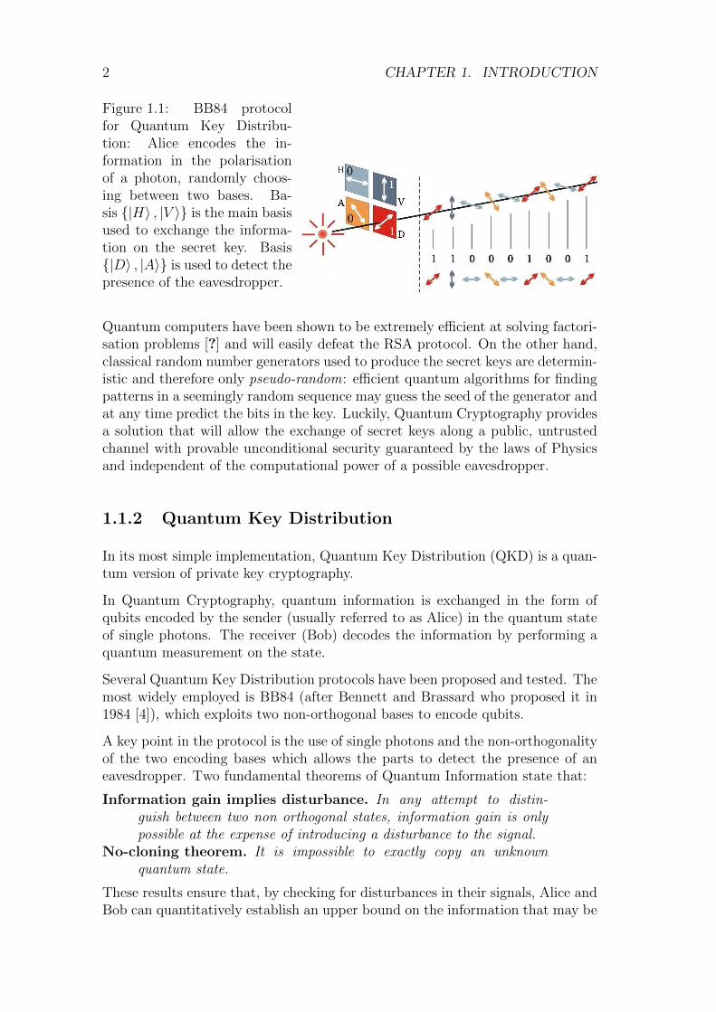
1.1 BB84 protocol for Quantum Key Distribution: Alice encodes theinformation in the polarisation of a photon, randomly choosingbetween two bases. Basis |H〉 , |V 〉 is the main basis used toexchange the information on the secret key. Basis |D〉 , |A〉 isused to detect the presence of the eavesdropper. . . . . . . . . . . 2
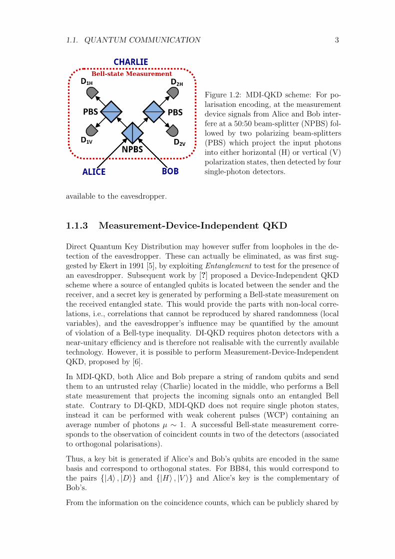
1.2 MDI-QKD scheme: For polarisation encoding, at the measurementdevice signals from Alice and Bob interfere at a 50:50 beam-splitter(NPBS) followed by two polarizing beam-splitters (PBS) whichproject the input photons into either horizontal (H) or vertical (V)polarization states, then detected by four single-photon detectors. 3
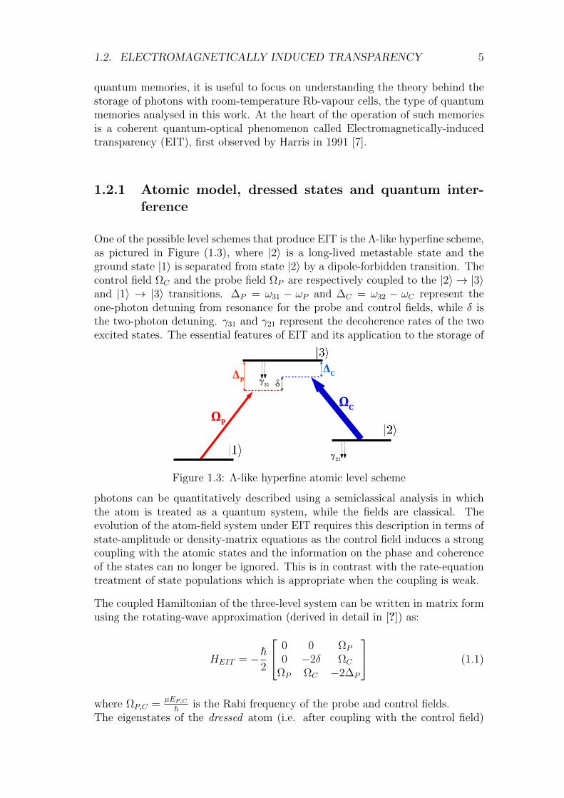
1.3 Λ-like hyperfine atomic level scheme . . . . . . . . . . . . . . . . . 5
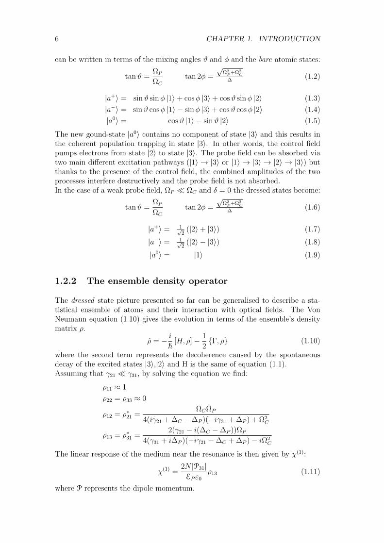
1.4 Evolution of the dark-state polariton ψ (top), probe field EP (bottom-left), and atomic excitation ρ12 (bottom-right). From [1]. . . . . . 8
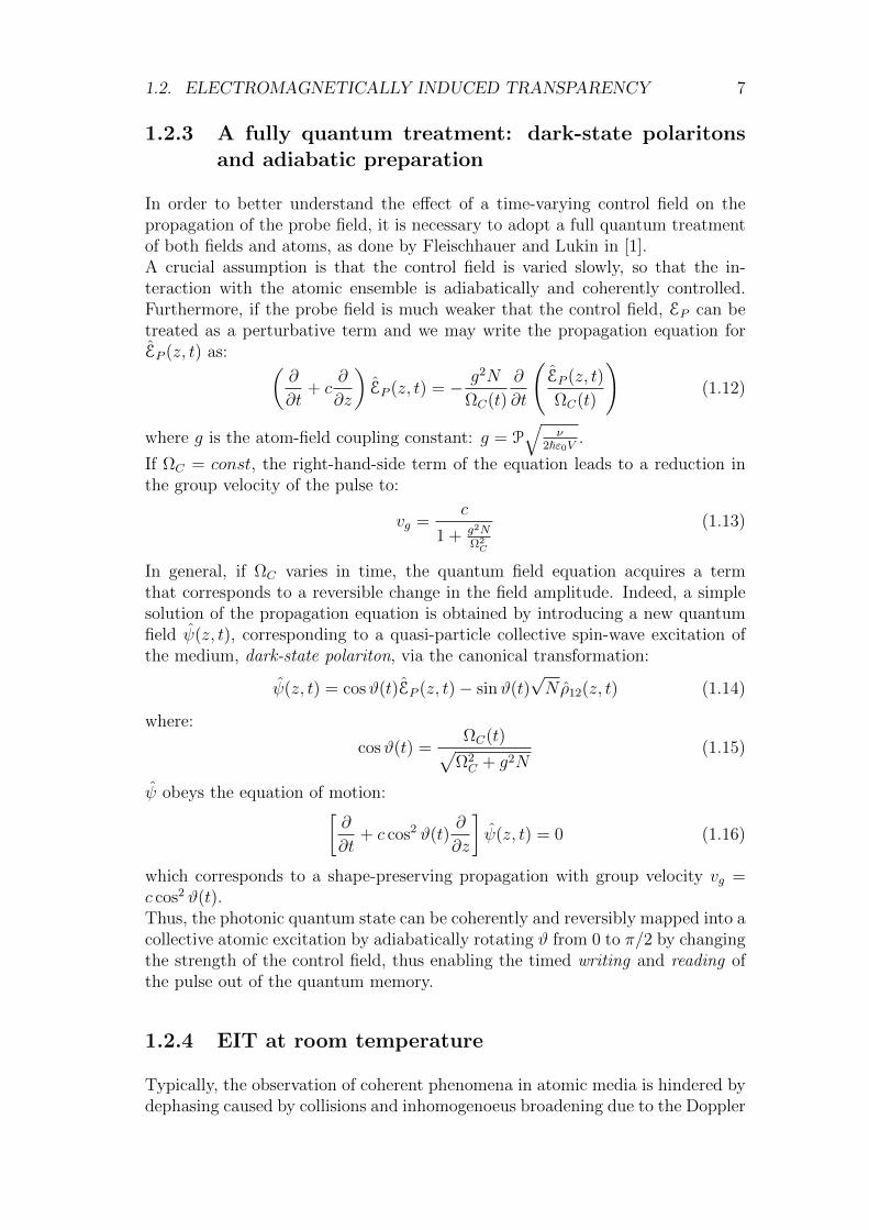
1.5 Imaginary term of the linear susceptibility χ(1) under conditions ofEIT as a function of the probe field detuning ∆P , normalised overthe dephasing rate γ31, under the assumption of weak decoherence:γ21 = 10−4γ31. The transparency window widens increasing therelative strength of the control field. The blue line corresponds toΩC = 0. . . . . . . . . . . . . . . . . . . . . . . . . . . . . . . . . 9
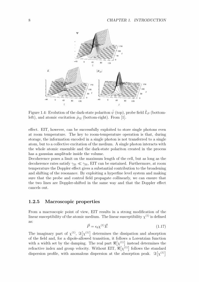
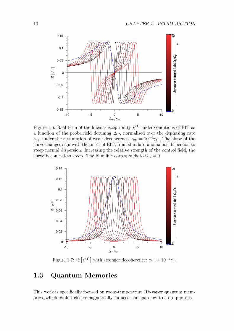
1.6 Real term of the linear susceptibility χ(1) under conditions of EITas a function of the probe field detuning ∆P , normalised over thedephasing rate γ31, under the assumption of weak decoherence:γ21 = 10−4γ31. The slope of the curve changes sign with the onsetof EIT, from standard anomalous dispersion to steep normal dis-persion. Increasing the relative strength of the control field, thecurve becomes less steep. The blue line corresponds to ΩC = 0. . . 10
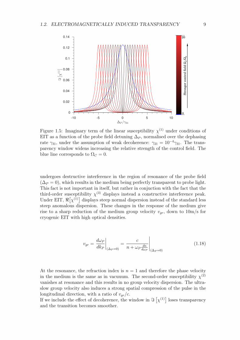
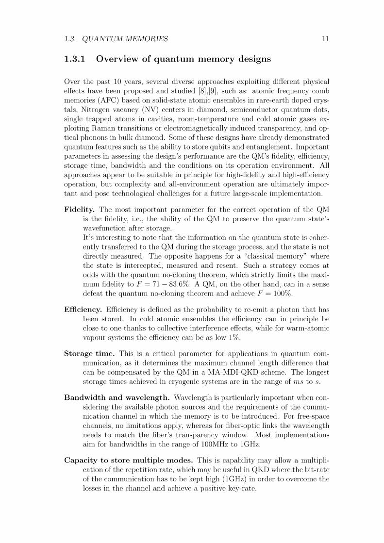
1.7 =[χ(1)]
with stronger decoherence: γ21 = 10−1γ31 . . . . . . . . . 10
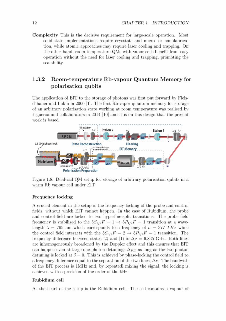
1.8 Dual-rail QM setup for storage of arbitrary polarisation qubits ina warm Rb vapour cell under EIT . . . . . . . . . . . . . . . . . . 12
v
vi LIST OF FIGURES
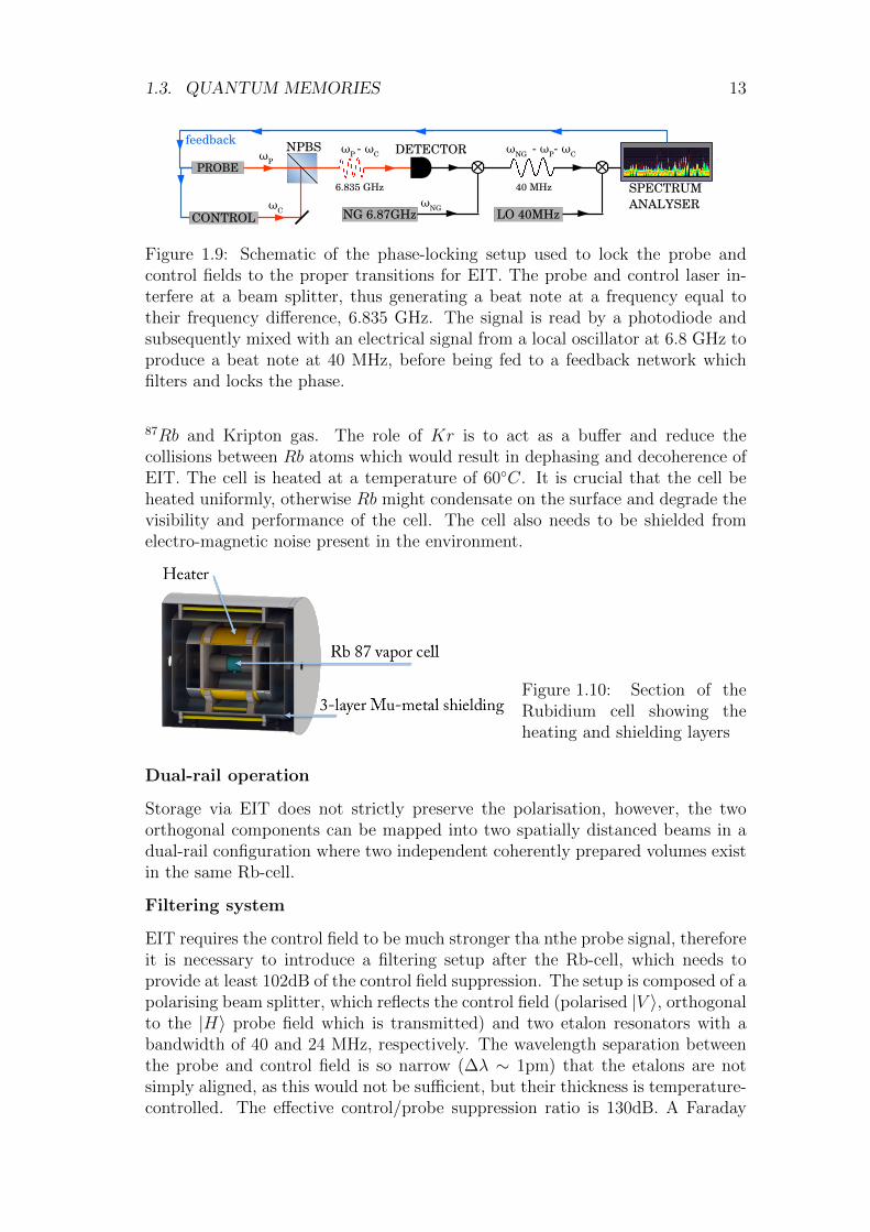
1.9 Schematic of the phase-locking setup used to lock the probe andcontrol fields to the proper transitions for EIT. The probe andcontrol laser interfere at a beam splitter, thus generating a beatnote at a frequency equal to their frequency difference, 6.835 GHz.The signal is read by a photodiode and subsequently mixed withan electrical signal from a local oscillator at 6.8 GHz to produce abeat note at 40 MHz, before being fed to a feedback network whichfilters and locks the phase. . . . . . . . . . . . . . . . . . . . . . . 13
1.10 Section of the Rubidium cell showing the heating and shielding layers 13
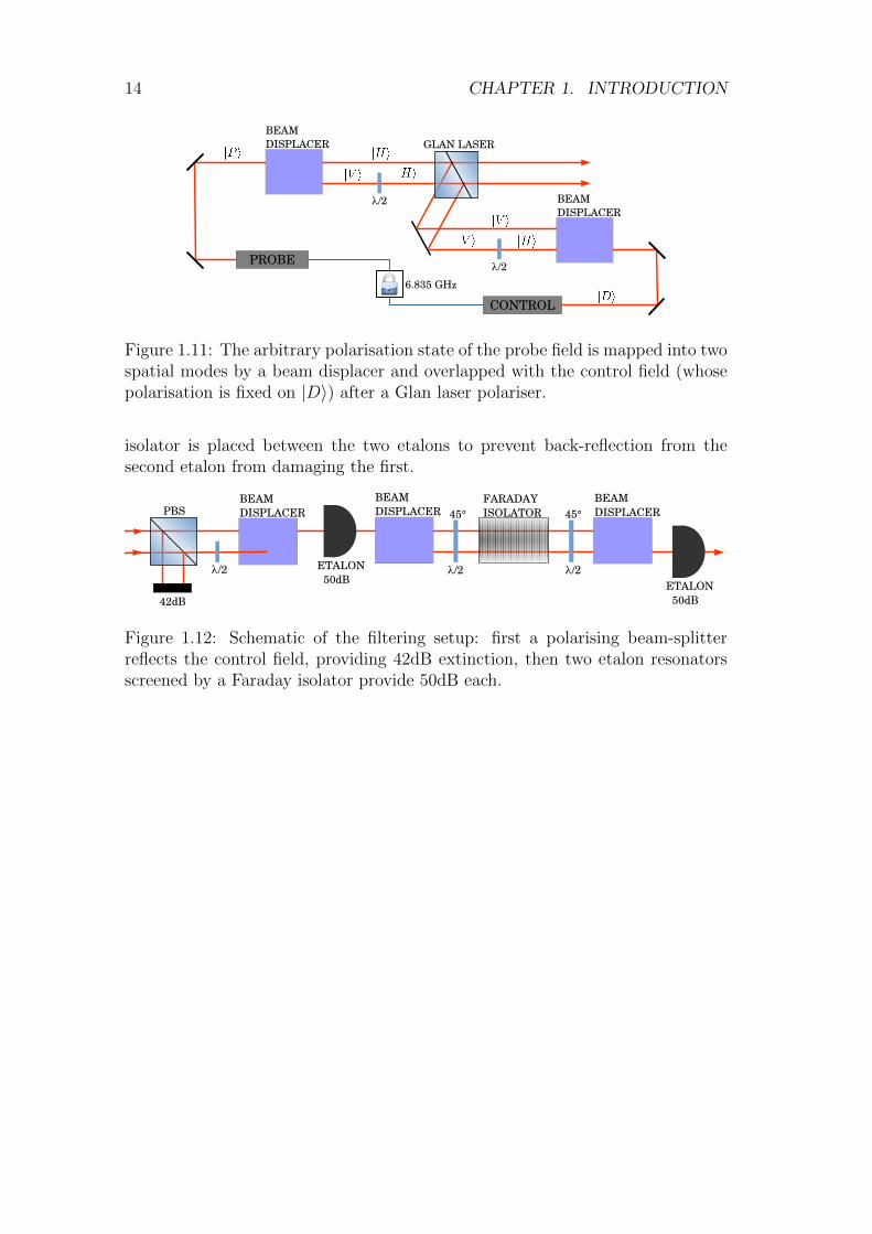
1.11 The arbitrary polarisation state of the probe field is mapped intotwo spatial modes by a beam displacer and overlapped with thecontrol field (whose polarisation is fixed on |D〉) after a Glan laserpolariser. . . . . . . . . . . . . . . . . . . . . . . . . . . . . . . . . 14
1.12 Schematic of the filtering setup: first a polarising beam-splitter re-flects the control field, providing 42dB extinction, then two etalonresonators screened by a Faraday isolator provide 50dB each. . . . 14
2.1 . . . . . . . . . . . . . . . . . . . . . . . . . . . . . . . . . . . . . 15
2.2 QBER vs mean photon number, colour-coded by key generationrate. The intersection between light blue and dark blue (negativekey rate area) corresponds to the boundary for the positive keyrate. The white dots indicate the bare and noise-free regimes.From [2] . . . . . . . . . . . . . . . . . . . . . . . . . . . . . . . . 16
4.1 HOM interference with single photons . . . . . . . . . . . . . . . . 22
4.2 Setup for HOM interference . . . . . . . . . . . . . . . . . . . . . 22
4.3 Zoomed-out view of the 1MHz beat-note interference fringes forCW operation. . . . . . . . . . . . . . . . . . . . . . . . . . . . . 24
4.4 Classical interference of two continuous wave beams, 1MHz-shiftedin frequency. . . . . . . . . . . . . . . . . . . . . . . . . . . . . . . 24
4.5 Classical interference of two 400ns-long pulses, 5MHz-shifted infrequency. . . . . . . . . . . . . . . . . . . . . . . . . . . . . . . . 25
4.6 Histrogram with the unfiltered counts in detector 1 and 2. . . . . 26
4.7 Filtered histogram corresponding single-photon counts for both de-tectors. . . . . . . . . . . . . . . . . . . . . . . . . . . . . . . . . . 26
4.8 HOM dip for two-photon coincidences, filtered on time bins at thepulse peak . . . . . . . . . . . . . . . . . . . . . . . . . . . . . . . 27
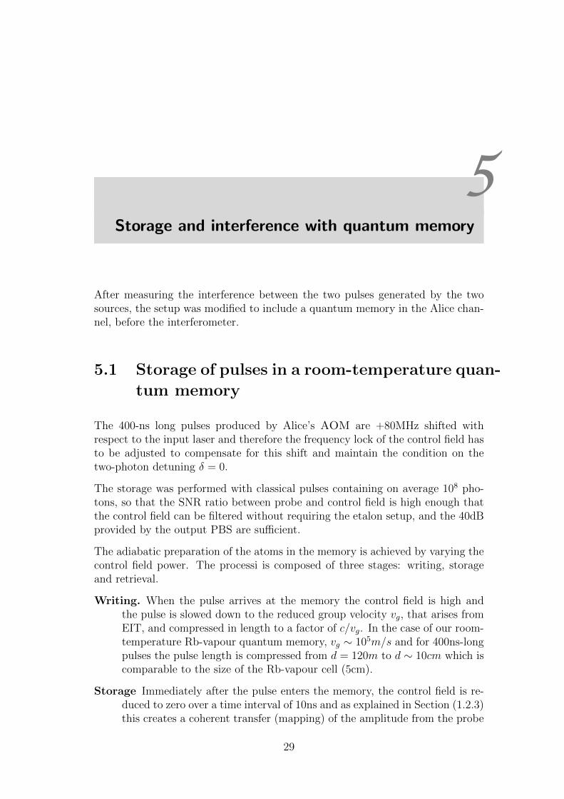
5.1 Cartoon representation of the storage process: (a) Time variationof the control field. (b) Storage under ideal conditions. (c) Realis-tic storage. . . . . . . . . . . . . . . . . . . . . . . . . . . . . . . . 30
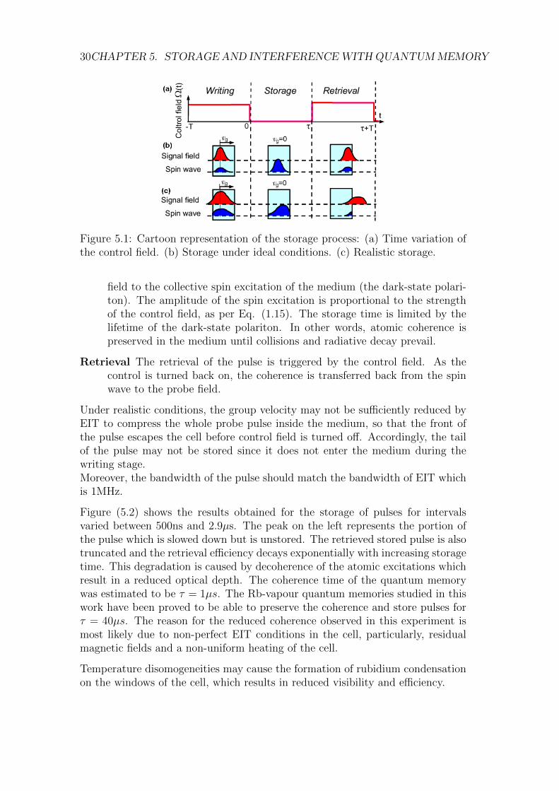
5.2 Retrieved pulse shape after different storage times. Decoherencecauses an exponential decay of the storage efficiency. . . . . . . . 31
LIST OF FIGURES vii
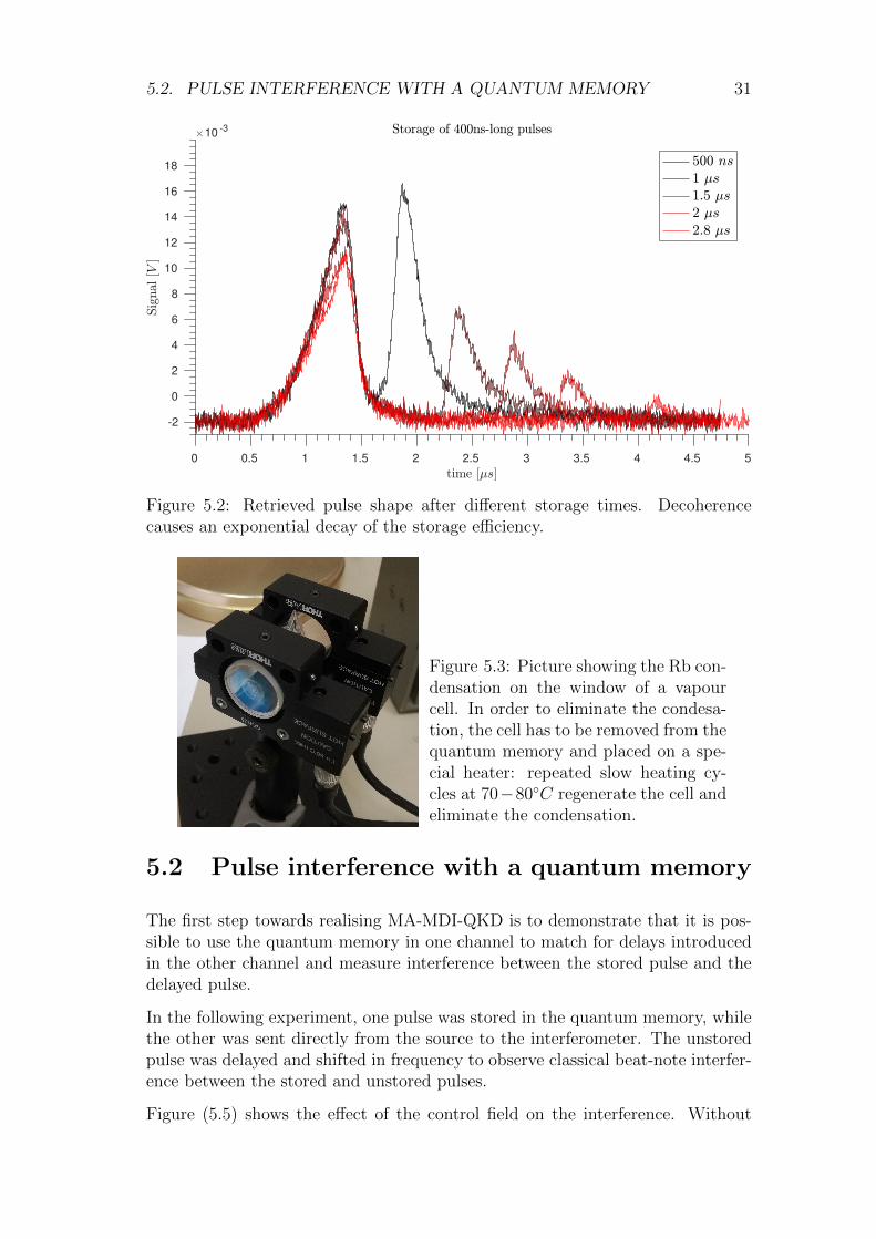
5.3 Picture showing the Rb condensation on the window of a vapourcell. In order to eliminate the condesation, the cell has to beremoved from the quantum memory and placed on a special heater:repeated slow heating cycles at 70− 80C regenerate the cell andeliminate the condensation. . . . . . . . . . . . . . . . . . . . . . 31
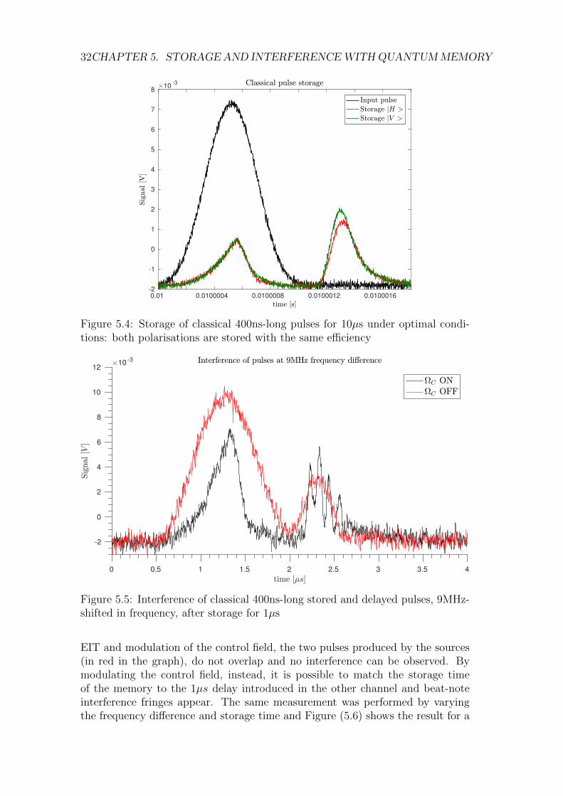
5.4 Storage of classical 400ns-long pulses for 10µs under optimal con-ditions: both polarisations are stored with the same efficiency . . 32
5.5 Interference of classical 400ns-long stored and delayed pulses, 9MHz-shifted in frequency, after storage for 1µs . . . . . . . . . . . . . . 32
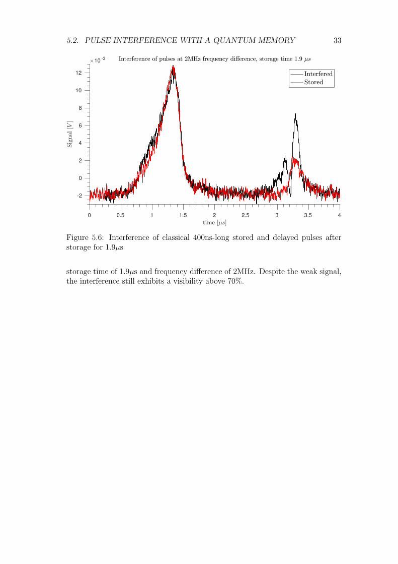
5.6 Interference of classical 400ns-long stored and delayed pulses afterstorage for 1.9µs . . . . . . . . . . . . . . . . . . . . . . . . . . . 33
6.1 Typical scheme for n-mosfet gate switching with bootstrap tech-nique . . . . . . . . . . . . . . . . . . . . . . . . . . . . . . . . . . 37
6.2 Schematic and simulation results of one of the three switches. . . 396.3 Output pulse signal Vout (blue), gate signal Vgate (green) and gate
current IRgate (red). The simulation shows that the current sourcedand sunk by the gate driver (±150mA) is within the operationallimits of the IR2117. . . . . . . . . . . . . . . . . . . . . . . . . . 39
6.4 Complete circuit schematic . . . . . . . . . . . . . . . . . . . . . . 406.5 PCB layout: top layer (red) and bottom layer (blue) . . . . . . . 406.6 Design schematic of the FPGA digital interface . . . . . . . . . . 41
7.1 Upgrade of the experiement to perform MA-MDI-QKD . . . . . . 45
A.1 q-plate between cross polarisers. . . . . . . . . . . . . . . . . . . . 49A.2 Unconverted power as a function of the voltage applied to the q-
plate: the minimum corresponds to the optimal tuning. . . . . . . 50A.3 Intensity distribution of vortex beams at different distances . . . . 51A.4 Comparison of cut and averaged profiles at z=500mm . . . . . . . 51A.5 Convergence of the LG and opt-LG models as a function of the
number of modes . . . . . . . . . . . . . . . . . . . . . . . . . . . 53A.6 Convergence of the models for z=500m, n=50 modes . . . . . . . 53A.7 Convergence of the models for z=500m, n=100 modes . . . . . . . 53A.8 Convergence of the models for z=4300m, n=10 modes . . . . . . . 54A.9 Vortex radius as a function of the distance from the q-plate. . . . 54A.10 Enclosed-energy radius as a function of the distance from the q-plate 55A.11 a . . . . . . . . . . . . . . . . . . . . . . . . . . . . . . . . . . . . 56A.12 From [3]: Zernike projection of vortex l = 1. The piston term
n = 0, not shown completely, is equal to π3/2 . . . . . . . . . . . . 57A.13 Wavefront for a superposition of OAM states l = 1 and l = 2. . . 58

viii LIST OF FIGURES
1Introduction
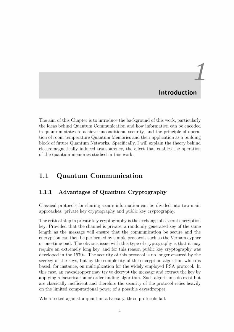
The aim of this Chapter is to introduce the background of this work, particularlythe ideas behind Quantum Communication and how information can be encodedin quantum states to achieve unconditional security, and the principle of opera-tion of room-temperature Quantum Memories and their application as a buildingblock of future Quantum Networks. Specifically, I will explain the theory behindelectromagnetically induced transparency, the effect that enables the operationof the quantum memories studied in this work.
1.1 Quantum Communication
1.1.1 Advantages of Quantum Cryptography
Classical protocols for sharing secure information can be divided into two mainapproaches: private key cryptography and public key cryptography.
The critical step in private key cryptography is the exchange of a secret encryptionkey. Provided that the channel is private, a randomly generated key of the samelength as the message will ensure that the communication be secure and theencryption can then be performed by simple prococols such as the Vernam cypheror one-time pad. The obvious issue with this type of cryptography is that it mayrequire an extremely long key, and for this reason public key cryptography wasdeveloped in the 1970s. The security of this protocol is no longer ensured by thesecrecy of the keys, but by the complexity of the encryption algorithm which isbased, for instance, on multiplication for the widely employed RSA protocol. Inthis case, an eavesdropper may try to decrypt the message and extract the key byapplying a factorisation or order-finding algorithm. Such algorithms do exist butare classically inefficient and therefore the security of the protocol relies heavilyon the limited computational power of a possible eavesdropper.
When tested against a quantum adversary, these protocols fail.
1
2 CHAPTER 1. INTRODUCTION
Figure 1.1: BB84 protocolfor Quantum Key Distribu-tion: Alice encodes the in-formation in the polarisationof a photon, randomly choos-ing between two bases. Ba-sis |H〉 , |V 〉 is the main basisused to exchange the informa-tion on the secret key. Basis|D〉 , |A〉 is used to detect thepresence of the eavesdropper.
Quantum computers have been shown to be extremely efficient at solving factori-sation problems [?] and will easily defeat the RSA protocol. On the other hand,classical random number generators used to produce the secret keys are determin-istic and therefore only pseudo-random: efficient quantum algorithms for findingpatterns in a seemingly random sequence may guess the seed of the generator andat any time predict the bits in the key. Luckily, Quantum Cryptography providesa solution that will allow the exchange of secret keys along a public, untrustedchannel with provable unconditional security guaranteed by the laws of Physicsand independent of the computational power of a possible eavesdropper.
1.1.2 Quantum Key Distribution
In its most simple implementation, Quantum Key Distribution (QKD) is a quan-tum version of private key cryptography.
In Quantum Cryptography, quantum information is exchanged in the form ofqubits encoded by the sender (usually referred to as Alice) in the quantum stateof single photons. The receiver (Bob) decodes the information by performing aquantum measurement on the state.
Several Quantum Key Distribution protocols have been proposed and tested. Themost widely employed is BB84 (after Bennett and Brassard who proposed it in1984 [4]), which exploits two non-orthogonal bases to encode qubits.
A key point in the protocol is the use of single photons and the non-orthogonalityof the two encoding bases which allows the parts to detect the presence of aneavesdropper. Two fundamental theorems of Quantum Information state that:
Information gain implies disturbance. In any attempt to distin-guish between two non orthogonal states, information gain is onlypossible at the expense of introducing a disturbance to the signal.
No-cloning theorem. It is impossible to exactly copy an unknownquantum state.
These results ensure that, by checking for disturbances in their signals, Alice andBob can quantitatively establish an upper bound on the information that may be
1.1. QUANTUM COMMUNICATION 3
Figure 1.2: MDI-QKD scheme: For po-larisation encoding, at the measurementdevice signals from Alice and Bob inter-fere at a 50:50 beam-splitter (NPBS) fol-lowed by two polarizing beam-splitters(PBS) which project the input photonsinto either horizontal (H) or vertical (V)polarization states, then detected by foursingle-photon detectors.
available to the eavesdropper.
1.1.3 Measurement-Device-Independent QKD
Direct Quantum Key Distribution may however suffer from loopholes in the de-tection of the eavesdropper. These can actually be eliminated, as was first sug-gested by Ekert in 1991 [5], by exploiting Entanglement to test for the presence ofan eavesdropper. Subsequent work by [?] proposed a Device-Independent QKDscheme where a source of entangled qubits is located between the sender and thereceiver, and a secret key is generated by performing a Bell-state measurement onthe received entangled state. This would provide the parts with non-local corre-lations, i.e., correlations that cannot be reproduced by shared randomness (localvariables), and the eavesdropper’s influence may be quantified by the amountof violation of a Bell-type inequality. DI-QKD requires photon detectors with anear-unitary efficiency and is therefore not realisable with the currently availabletechnology. However, it is possible to perform Measurement-Device-IndependentQKD, proposed by [6].
In MDI-QKD, both Alice and Bob prepare a string of random qubits and sendthem to an untrusted relay (Charlie) located in the middle, who performs a Bellstate measurement that projects the incoming signals onto an entangled Bellstate. Contrary to DI-QKD, MDI-QKD does not require single photon states,instead it can be performed with weak coherent pulses (WCP) containing anaverage number of photons µ ∼ 1. A successful Bell-state measurement corre-sponds to the observation of coincident counts in two of the detectors (associatedto orthogonal polarisations).
Thus, a key bit is generated if Alice’s and Bob’s qubits are encoded in the samebasis and correspond to orthogonal states. For BB84, this would correspond tothe pairs |A〉 , |D〉 and |H〉 , |V 〉 and Alice’s key is the complementary ofBob’s.
From the information on the coincidence counts, which can be publicly shared by
4 CHAPTER 1. INTRODUCTION
Coincidence Bell state
D1H ∧D2V |ψ−〉 = 1/√
2 (|HV 〉 − |V H〉)D1V ∧D2H |ψ−〉D1H ∧D1V |ψ+〉 = 1/
√2 (|HV 〉+ |V H〉)
D2H ∧D2V |ψ+〉
Table 1.1: Coincidence table for the Bell-state measurement
Charlie, Alice and Bob can then establish a correlation between their qubits andextract a secret key. Unlike direct QKD, the key bits are not directly encoded inthe string measured by Bob, but the information on the key is only created aftera successful Bell-state measurement. In order to guess the key, the eavesdropperwould need both the information on the coincidence counts, and the informationon the two strings that are being sent by Alice and Bob. Since their laboratoriesare well shielded and they exchange states with a subunitary mean photon num-ber, the eavesdropper cannot gain information by the mere coincidence counts,nor can he gain it by intercepting the flying qubits, as no information is encodedin them unless a successful Bell-state measurement is performed.
1.1.4 Memory-assisted MDI-QKD
Memory-assisted-MDI-QKD is an extension of MDI-QKD, which inherits its re-silience against detector attacks, and enhances its rate scaling.
MDI-QKD can only generate key bits if a successful Bell-state measurement isperformed, and this presumes that the two single photons arrive at the interferingbeam-splitter synchronised. In an out-of-the-lab implementation, the length ofthe two communication channels may not always be identical, or even stabilised.In MA-MDI-QKD, the photons transmitted by the users are stored each in aQM before the Bell-state measurement. This allows the pulses to be dynamicallysincronised and the protocol to work even for communication channels that inprinciple differ by kilometers (for storage times of the order of 10µs). The per-formance of such a scheme is moreover enhanced if the storage in the quantummemory can be heralded. In such a scheme, when a memorisation event occurs anadditional “heralding” photon is emitted by the quantum memory and, by imple-menting a coincidence setup, it is possible to filter only the actual memorisationevents and discard noise.
1.2 Electromagnetically Induced Transparency
Quantum memories (QMs), are quantum light-matter interfaces capable of re-ceiving, storing and retrieving photonic qubits with a higher fidelity than anyclassical device. Before moving on to explaining the design and operation of
1.2. ELECTROMAGNETICALLY INDUCED TRANSPARENCY 5
quantum memories, it is useful to focus on understanding the theory behind thestorage of photons with room-temperature Rb-vapour cells, the type of quantummemories analysed in this work. At the heart of the operation of such memoriesis a coherent quantum-optical phenomenon called Electromagnetically-inducedtransparency (EIT), first observed by Harris in 1991 [7].
1.2.1 Atomic model, dressed states and quantum inter-ference
One of the possible level schemes that produce EIT is the Λ-like hyperfine scheme,as pictured in Figure (1.3), where |2〉 is a long-lived metastable state and theground state |1〉 is separated from state |2〉 by a dipole-forbidden transition. Thecontrol field ΩC and the probe field ΩP are respectively coupled to the |2〉 → |3〉and |1〉 → |3〉 transitions. ∆P = ω31 − ωP and ∆C = ω32 − ωC represent theone-photon detuning from resonance for the probe and control fields, while δ isthe two-photon detuning. γ31 and γ21 represent the decoherence rates of the twoexcited states. The essential features of EIT and its application to the storage of
ΩC
ΩP
ΔCΔP δγ31
γ21
Figure 1.3: Λ-like hyperfine atomic level scheme
photons can be quantitatively described using a semiclassical analysis in whichthe atom is treated as a quantum system, while the fields are classical. Theevolution of the atom-field system under EIT requires this description in terms ofstate-amplitude or density-matrix equations as the control field induces a strongcoupling with the atomic states and the information on the phase and coherenceof the states can no longer be ignored. This is in contrast with the rate-equationtreatment of state populations which is appropriate when the coupling is weak.
The coupled Hamiltonian of the three-level system can be written in matrix formusing the rotating-wave approximation (derived in detail in [?]) as:
HEIT = −2
0 0 ΩP
0 −2δ ΩC
ΩP ΩC −2∆P
(1.1)
where ΩP,C =µEP,C
is the Rabi frequency of the probe and control fields.The eigenstates of the dressed atom (i.e. after coupling with the control field)
6 CHAPTER 1. INTRODUCTION
can be written in terms of the mixing angles ϑ and φ and the bare atomic states:
tanϑ =ΩP
ΩC
tan 2φ =
√Ω2
P +Ω2C
∆(1.2)
|a+〉 = sinϑ sinφ |1〉+ cosφ |3〉+ cosϑ sinφ |2〉 (1.3)
|a−〉 = sinϑ cosφ |1〉 − sinφ |3〉+ cosϑ cosφ |2〉 (1.4)
|a0〉 = cosϑ |1〉 − sinϑ |2〉 (1.5)
The new gound-state |a0〉 contains no component of state |3〉 and this results inthe coherent population trapping in state |3〉. In other words, the control fieldpumps electrons from state |2〉 to state |3〉. The probe field can be absorbed viatwo main different excitation pathways (|1〉 → |3〉 or |1〉 → |3〉 → |2〉 → |3〉) butthanks to the presence of the control field, the combined amplitudes of the twoprocesses interfere destructively and the probe field is not absorbed.In the case of a weak probe field, ΩP ΩC and δ = 0 the dressed states become:
tanϑ =ΩP
ΩC
tan 2φ =
√Ω2
P +Ω2C
∆(1.6)
|a+〉 = 1√2
(|2〉+ |3〉) (1.7)
|a−〉 = 1√2
(|2〉 − |3〉) (1.8)
|a0〉 = |1〉 (1.9)
1.2.2 The ensemble density operator
The dressed state picture presented so far can be generalised to describe a sta-tistical ensemble of atoms and their interaction with optical fields. The VonNeumann equation (1.10) gives the evolution in terms of the ensemble’s densitymatrix ρ.
ρ = − i
[H, ρ]− 1
2Γ, ρ (1.10)
where the second term represents the decoherence caused by the spontaneousdecay of the excited states |3〉,|2〉 and H is the same of equation (1.1).Assuming that γ21 γ31, by solving the equation we find:
ρ11 ≈ 1
ρ22 = ρ33 ≈ 0
ρ12 = ρ∗21 =ΩCΩP
4(iγ21 + ∆C −∆P )(−iγ31 + ∆P ) + Ω2C
ρ13 = ρ∗31 =2(γ21 − i(∆C −∆P ))ΩP
4(γ31 + i∆P )(−iγ21 −∆C + ∆P )− iΩ2C
The linear response of the medium near the resonance is then given by χ(1):
χ(1) =2N |P31|EP ε0
ρ13 (1.11)
where P represents the dipole momentum.
1.2. ELECTROMAGNETICALLY INDUCED TRANSPARENCY 7
1.2.3 A fully quantum treatment: dark-state polaritonsand adiabatic preparation
In order to better understand the effect of a time-varying control field on thepropagation of the probe field, it is necessary to adopt a full quantum treatmentof both fields and atoms, as done by Fleischhauer and Lukin in [1].A crucial assumption is that the control field is varied slowly, so that the in-teraction with the atomic ensemble is adiabatically and coherently controlled.Furthermore, if the probe field is much weaker that the control field, EP can betreated as a perturbative term and we may write the propagation equation forEP (z, t) as: (
∂
∂t+ c
∂
∂z
)EP (z, t) = − g2N
ΩC(t)
∂
∂t
(EP (z, t)
ΩC(t)
)(1.12)
where g is the atom-field coupling constant: g = P√
ν2ε0V .
If ΩC = const, the right-hand-side term of the equation leads to a reduction inthe group velocity of the pulse to:
vg =c
1 + g2NΩ2
C
(1.13)
In general, if ΩC varies in time, the quantum field equation acquires a termthat corresponds to a reversible change in the field amplitude. Indeed, a simplesolution of the propagation equation is obtained by introducing a new quantumfield ψ(z, t), corresponding to a quasi-particle collective spin-wave excitation ofthe medium, dark-state polariton, via the canonical transformation:
ψ(z, t) = cosϑ(t)EP (z, t)− sinϑ(t)√Nρ12(z, t) (1.14)
where:
cosϑ(t) =ΩC(t)√
Ω2C + g2N
(1.15)
ψ obeys the equation of motion:[∂
∂t+ c cos2 ϑ(t)
∂
∂z
]ψ(z, t) = 0 (1.16)
which corresponds to a shape-preserving propagation with group velocity vg =c cos2 ϑ(t).Thus, the photonic quantum state can be coherently and reversibly mapped into acollective atomic excitation by adiabatically rotating ϑ from 0 to π/2 by changingthe strength of the control field, thus enabling the timed writing and reading ofthe pulse out of the quantum memory.
1.2.4 EIT at room temperature
Typically, the observation of coherent phenomena in atomic media is hindered bydephasing caused by collisions and inhomogenoeus broadening due to the Doppler
8 CHAPTER 1. INTRODUCTION
Figure 1.4: Evolution of the dark-state polariton ψ (top), probe field EP (bottom-left), and atomic excitation ρ12 (bottom-right). From [1].
effect. EIT, however, can be successfully exploited to store single photons evenat room temperature. The key to room-temperature operation is that, duringstorage, the information encoded in a single photon is not transferred to a singleatom, but to a collective excitation of the medium. A single photon interacts withthe whole atomic ensemble and the dark-state polariton created in the processhas a gaussian amplitude inside the volume.Decoherence poses a limit on the maximum length of the cell, but as long as thedecoherence rates satisfy γ21 γ31, EIT can be sustained. Furthermore, at roomtemperature the Doppler effect gives a substantial contribution to the broadeningand shifting of the resonance. By exploiting a hyperfine level system and makingsure that the probe and control field propagate collinearly, we can ensure thatthe two lines are Doppler-shifted in the same way and that the Doppler effectcancels out.
1.2.5 Macroscopic properties
From a macroscopic point of view, EIT results in a strong modification of thelinear susceptibility of the atomic medium. The linear susceptibility χ(1) is definedas:
~P = ε0χ(1) ~E (1.17)
The imaginary part of χ(1), =[χ(1)]
determines the dissipation and absorptionof the field and, for a dipole-allowed transition, it follows a Lorentzian functionwith a width set by the damping. The real part <
[χ(1)]
instead determines the
refractive index and group velocity. Without EIT, <[χ(1)]
follows the standard
dispersion profile, with anomalous dispersion at the absorption peak. =[χ(1)]
1.2. ELECTROMAGNETICALLY INDUCED TRANSPARENCY 9
-10 -5 0 5 10
0
0.02
0.04
0.06
0.08
0.1
0.12
0.14
0
20
Stro
n ger
con
tro l
fiel
d Ω
C/Ω
P
Figure 1.5: Imaginary term of the linear susceptibility χ(1) under conditions ofEIT as a function of the probe field detuning ∆P , normalised over the dephasingrate γ31, under the assumption of weak decoherence: γ21 = 10−4γ31. The trans-parency window widens increasing the relative strength of the control field. Theblue line corresponds to ΩC = 0.
undergoes destructive interference in the region of resonance of the probe field(∆P = 0), which results in the medium being perfectly transparent to probe light.This fact is not important in itself, but rather in conjuction with the fact that thethird-order susceptibility χ(3) displays instead a constructive interference peak.Under EIT, <
[χ(1)]
displays steep normal dispersion instead of the standard lesssteep anomalous dispersion. These changes in the response of the medium giverise to a sharp reduction of the medium group velocity vgr, down to 10m/s forcryogenic EIT with high optical densities.
vgr =dωPdkP
∣∣∣∣(∆P =0)
=c
n+ ωPdndωP
∣∣∣∣∣(∆P =0)
(1.18)
At the resonance, the refraction index is n = 1 and therefore the phase velocityin the medium is the same as in vacuuum. The second-order susceptibility χ(2)
vanishes at resonance and this results in no group velocity dispersion. The ultra-slow group velocity also induces a strong spatial compression of the pulse in thelongitudinal direction, with a ratio of vgr/c.If we include the effect of decoherence, the window in =
[χ(1)]
loses transparencyand the transition becomes smoother.
10 CHAPTER 1. INTRODUCTION
-10 -5 0 5 10
-0.15
-0.1
-0.05
0
0.05
0.1
0.15
0
20
Stro
n ger
con
tro l
fiel
d Ω
C/Ω
P
Figure 1.6: Real term of the linear susceptibility χ(1) under conditions of EIT asa function of the probe field detuning ∆P , normalised over the dephasing rateγ31, under the assumption of weak decoherence: γ21 = 10−4γ31. The slope of thecurve changes sign with the onset of EIT, from standard anomalous dispersion tosteep normal dispersion. Increasing the relative strength of the control field, thecurve becomes less steep. The blue line corresponds to ΩC = 0.
-10 -5 0 5 10
0
0.02
0.04
0.06
0.08
0.1
0.12
0.14
0
20
Stro
n ger
con
tro l
fiel
d Ω
C/Ω
P
Figure 1.7: =[χ(1)]
with stronger decoherence: γ21 = 10−1γ31
1.3 Quantum Memories
This work is specifically focused on room-temperature Rb-vapor quantum mem-ories, which exploit electromagnetically-induced transparency to store photons.
1.3. QUANTUM MEMORIES 11
1.3.1 Overview of quantum memory designs
Over the past 10 years, several diverse approaches exploiting different physicaleffects have been proposed and studied [8],[9], such as: atomic frequency combmemories (AFC) based on solid-state atomic ensembles in rare-earth doped crys-tals, Nitrogen vacancy (NV) centers in diamond, semiconductor quantum dots,single trapped atoms in cavities, room-temperature and cold atomic gases ex-ploiting Raman transitions or electromagnetically induced transparency, and op-tical phonons in bulk diamond. Some of these designs have already demonstratedquantum features such as the ability to store qubits and entanglement. Importantparameters in assessing the design’s performance are the QM’s fidelity, efficiency,storage time, bandwidth and the conditions on its operation environment. Allapproaches appear to be suitable in principle for high-fidelity and high-efficiencyoperation, but complexity and all-environment operation are ultimately impor-tant and pose technological challenges for a future large-scale implementation.
Fidelity. The most important parameter for the correct operation of the QMis the fidelity, i.e., the ability of the QM to preserve the quantum state’swavefunction after storage.It’s interesting to note that the information on the quantum state is coher-ently transferred to the QM during the storage process, and the state is notdirectly measured. The opposite happens for a “classical memory” wherethe state is intercepted, measured and resent. Such a strategy comes atodds with the quantum no-cloning theorem, which strictly limits the maxi-mum fidelity to F = 71− 83.6%. A QM, on the other hand, can in a sensedefeat the quantum no-cloning theorem and achieve F = 100%.
Efficiency. Efficiency is defined as the probability to re-emit a photon that hasbeen stored. In cold atomic ensembles the efficiency can in principle beclose to one thanks to collective interference effects, while for warm-atomicvapour systems the efficiency can be as low 1%.
Storage time. This is a critical parameter for applications in quantum com-munication, as it determines the maximum channel length difference thatcan be compensated by the QM in a MA-MDI-QKD scheme. The longeststorage times achieved in cryogenic systems are in the range of ms to s.
Bandwidth and wavelength. Wavelength is particularly important when con-sidering the available photon sources and the requirements of the commu-nication channel in which the memory is to be introduced. For free-spacechannels, no limitations apply, whereas for fiber-optic links the wavelengthneeds to match the fiber’s transparency window. Most implementationsaim for bandwidths in the range of 100MHz to 1GHz.
Capacity to store multiple modes. This is capability may allow a multipli-cation of the repetition rate, which may be useful in QKD where the bit-rateof the communication has to be kept high (1GHz) in order to overcome thelosses in the channel and achieve a positive key-rate.
12 CHAPTER 1. INTRODUCTION
Complexity This is the decisive requirement for large-scale operation. Mostsolid-state implementations require cryostats and micro- or nanofabrica-tion, while atomic approaches may require laser cooling and trapping. Onthe other hand, room temperature QMs with vapor cells benefit from easyoperation without the need for laser cooling and trapping, promoting thescalability.
1.3.2 Room-temperature Rb-vapour Quantum Memory forpolarisation qubits
The application of EIT to the storage of photons was first put forward by Fleis-chhauer and Lukin in 2000 [1]. The first Rb-vapor quantum memory for storageof an arbitrary polarisation state working at room temperature was realised byFigueroa and collaborators in 2014 [10] and it is on this design that the presentwork is based.
Figure 1.8: Dual-rail QM setup for storage of arbitrary polarisation qubits in awarm Rb vapour cell under EIT
Frequency locking
A crucial element in the setup is the frequency locking of the probe and controlfields, without which EIT cannot happen. In the case of Rubidium, the probeand control field are locked to two hyperfine-split transitions. The probe fieldfrequency is stabilized to the 5S1/2F = 1 → 5P1/2F = 1 transition at a wave-length λ = 795 nm which corresponds to a frequency of ν = 377 THz whilethe control field interacts with the 5S1/2F = 2 → 5P1/2F = 1 transition. Thefrequency difference between states |2〉 and |1〉 is ∆ν = 6.835 GHz. Both linesare inhomogeneously broadened by the Doppler effect and this ensures that EITcan happen even at large one-photon detunings ∆P,C as long as the two-photondetuning is locked at δ = 0. This is achieved by phase-locking the control field toa frequency difference equal to the separation of the two lines, ∆ν. The bandwithof the EIT process is 1MHz and, by repeatedl mixing the signal, the locking isachieved with a precision of the order of the kHz.
Rubidium cell
At the heart of the setup is the Rubidium cell. The cell contains a vapour of
1.3. QUANTUM MEMORIES 13
PROBE
NG 6.8GHz
NPBS DETECTORωP
ωC
ωP ωC
ωNG
ωNG ωP ωC
6.835 GHz 40 MHz
CONTROL LO 40MHzNG 6.87GHz
SPECTRUMANALYSER
feedback
Figure 1.9: Schematic of the phase-locking setup used to lock the probe andcontrol fields to the proper transitions for EIT. The probe and control laser in-terfere at a beam splitter, thus generating a beat note at a frequency equal totheir frequency difference, 6.835 GHz. The signal is read by a photodiode andsubsequently mixed with an electrical signal from a local oscillator at 6.8 GHz toproduce a beat note at 40 MHz, before being fed to a feedback network whichfilters and locks the phase.
87Rb and Kripton gas. The role of Kr is to act as a buffer and reduce thecollisions between Rb atoms which would result in dephasing and decoherence ofEIT. The cell is heated at a temperature of 60C. It is crucial that the cell beheated uniformly, otherwise Rb might condensate on the surface and degrade thevisibility and performance of the cell. The cell also needs to be shielded fromelectro-magnetic noise present in the environment.
Figure 1.10: Section of theRubidium cell showing theheating and shielding layers
Dual-rail operation
Storage via EIT does not strictly preserve the polarisation, however, the twoorthogonal components can be mapped into two spatially distanced beams in adual-rail configuration where two independent coherently prepared volumes existin the same Rb-cell.
Filtering system
EIT requires the control field to be much stronger tha nthe probe signal, thereforeit is necessary to introduce a filtering setup after the Rb-cell, which needs toprovide at least 102dB of the control field suppression. The setup is composed of apolarising beam splitter, which reflects the control field (polarised |V 〉, orthogonalto the |H〉 probe field which is transmitted) and two etalon resonators with abandwidth of 40 and 24 MHz, respectively. The wavelength separation betweenthe probe and control field is so narrow (∆λ ∼ 1pm) that the etalons are notsimply aligned, as this would not be sufficient, but their thickness is temperature-controlled. The effective control/probe suppression ratio is 130dB. A Faraday
14 CHAPTER 1. INTRODUCTION
PROBE
CONTROL
BEAM DISPLACER
BEAM DISPLACER
GLAN LASER
/2λ
/2λ6.835 GHz
Figure 1.11: The arbitrary polarisation state of the probe field is mapped into twospatial modes by a beam displacer and overlapped with the control field (whosepolarisation is fixed on |D〉) after a Glan laser polariser.
isolator is placed between the two etalons to prevent back-reflection from thesecond etalon from damaging the first.
BEAM DISPLACER
BEAM DISPLACERPBS
/2λ/2λ
FARADAYISOLATOR
/2λ
45°45°
ETALON 50dB
BEAM DISPLACER
42dBETALON 50dB
Figure 1.12: Schematic of the filtering setup: first a polarising beam-splitterreflects the control field, providing 42dB extinction, then two etalon resonatorsscreened by a Faraday isolator provide 50dB each.
2Outline and goals of this work
2.1 Context
The present work fits in the broader framework of an ongoing collaborationbetween the QuantumFuture research group at the University of Padova, andthe Quantum Information and Technology group at Stony Brook University(NY,USA). The main expertise of the group in Padova is Quantum Commu-nication, while Stony Brook focuses its research on the development of room-temperature Quantum Memories.
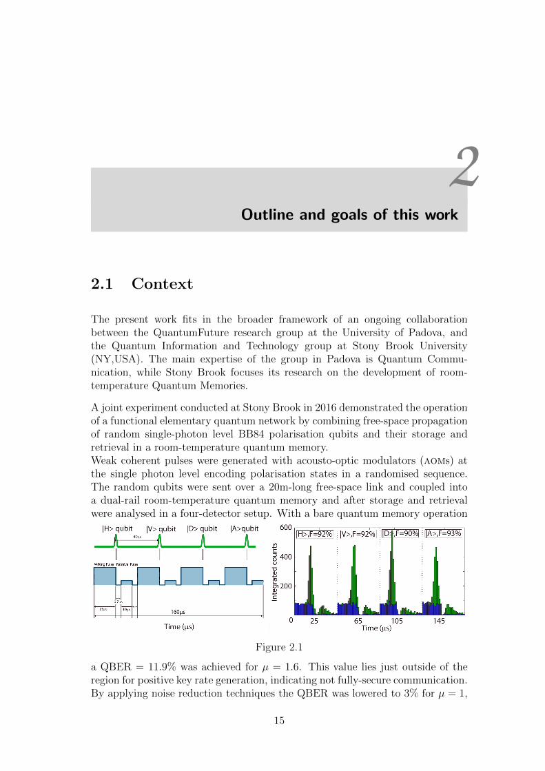
A joint experiment conducted at Stony Brook in 2016 demonstrated the operationof a functional elementary quantum network by combining free-space propagationof random single-photon level BB84 polarisation qubits and their storage andretrieval in a room-temperature quantum memory.Weak coherent pulses were generated with acousto-optic modulators (aoms) atthe single photon level encoding polarisation states in a randomised sequence.The random qubits were sent over a 20m-long free-space link and coupled intoa dual-rail room-temperature quantum memory and after storage and retrievalwere analysed in a four-detector setup. With a bare quantum memory operation
Figure 2.1
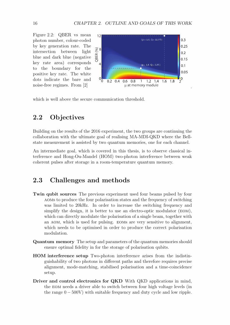
a QBER = 11.9% was achieved for µ = 1.6. This value lies just outside of theregion for positive key rate generation, indicating not fully-secure communication.By applying noise reduction techniques the QBER was lowered to 3% for µ = 1,
15
16 CHAPTER 2. OUTLINE AND GOALS OF THIS WORK
Figure 2.2: QBER vs meanphoton number, colour-codedby key generation rate. Theintersection between lightblue and dark blue (negativekey rate area) correspondsto the boundary for thepositive key rate. The whitedots indicate the bare andnoise-free regimes. From [2] .
which is well above the secure communication threshold.
2.2 Objectives
Building on the results of the 2016 experiment, the two groups are continuing thecollaboration with the ultimate goal of realising MA-MDI-QKD where the Bell-state measurement is assisted by two quantum memories, one for each channel.
An intermediate goal, which is covered in this thesis, is to observe classical in-terference and Hong-Ou-Mandel (HOM) two-photon interference between weakcoherent pulses after storage in a room-temperature quantum memory.
2.3 Challenges and methods
Twin qubit sources The previous experiment used four beams pulsed by fouraoms to produce the four polarisation states and the frequency of switchingwas limited to 20kHz. In order to increase the switching frequency andsimplify the design, it is better to use an electro-optic modulator (eom),which can directly modulate the polarisation of a single beam, together withan aom, which is used for pulsing. eoms are very sensitive to alignment,which needs to be optimised in order to produce the correct polarisationmodulation.
Quantum memory The setup and parameters of the quantum memories shouldensure optimal fidelity in for the storage of polarisation qubits.
HOM interference setup Two-photon interference arises from the indistin-guishability of two photons in different paths and therefore requires precisealignment, mode-matching, stabilised polarisation and a time-coincidencesetup.
Driver and control electronics for QKD With QKD applications in mind,the eom needs a driver able to switch between four high voltage levels (inthe range 0− 500V) with suitable frequency and duty cycle and low ripple.

2.3. CHALLENGES AND METHODS 17
In addition, the system needs a digital interface, implemented on an FPGA,which produces the triggers for the four voltage levels of the eom driver,for the aom and for the detectors.

18 CHAPTER 2. OUTLINE AND GOALS OF THIS WORK
3Setup of the twin qubit sources
The setup of the two qubit sources (Alice and Bob) is identical. The light for bothAlice and Bob is derived from the same laser source at 795nm, which is lockedto a control laser with a frequency difference of 8.35GHz. Two acousto-opticmodulators (aoms) generate two gaussian pulses 400ns-long with a repetitionrate of 20kHz. aoms are driven by a frequency modulation and an amplitudemodulation, which can be set on a DC level for CW operation. Because of thefrequency modulation at ν=80MHz, the aoms produce three output beams withfrequency shifts −ν, 0,+ν.
An iris selects the +ν component for both Alice and Bob, and these are thencoupled into two polarisation-maintaining (PM) fibers that reach the electro-optic polarisation setup. The mode entering the PM fiber is aligned at couplingwith the fast axis of the fiber, so that the polarisation at the output is stable withmore than 50dB of extinction ratio. At the output of the fiber, a half wave-platerotates the polarisation to horizontal while a polariser and quarter waveplateeliminate any residual ellipticity.
The electro-optic polarisation modulator (eom) is a Pockels cell type modulatorand consists of two lithium niobate (LiNbO3) crystals. Voltage applied across thecrystal structure induces change in the indices of refraction (both ordinary andextraordinary), leading to an electric field dependent birefringence. An opticalwave with polarisation components on both the ordinary and extraordinary axesof the crystal will experience a change in polarisation state arising from therelative phase delay between the orthogonal components. Thus, the electro-opticcrystal acts as a variable waveplate with retardance linearly dependent on theapplied voltage.
Lithium niobate exhibits a static temperature-dependent birefringence which maycause variations in the output polarisation. To minimize this effect, the twolithium niobate crystals are rotated 90 one with respect to the other so that thestatic birefrincence induced by the first is cancelled by the second crystal. Thisway, the temperature sensitivity of the crystal is typically < 1mrad/C. In orderfor the eom to produce the correct polarisation modulation, the beam needs to
19
20 CHAPTER 3. SETUP OF THE TWIN QUBIT SOURCES
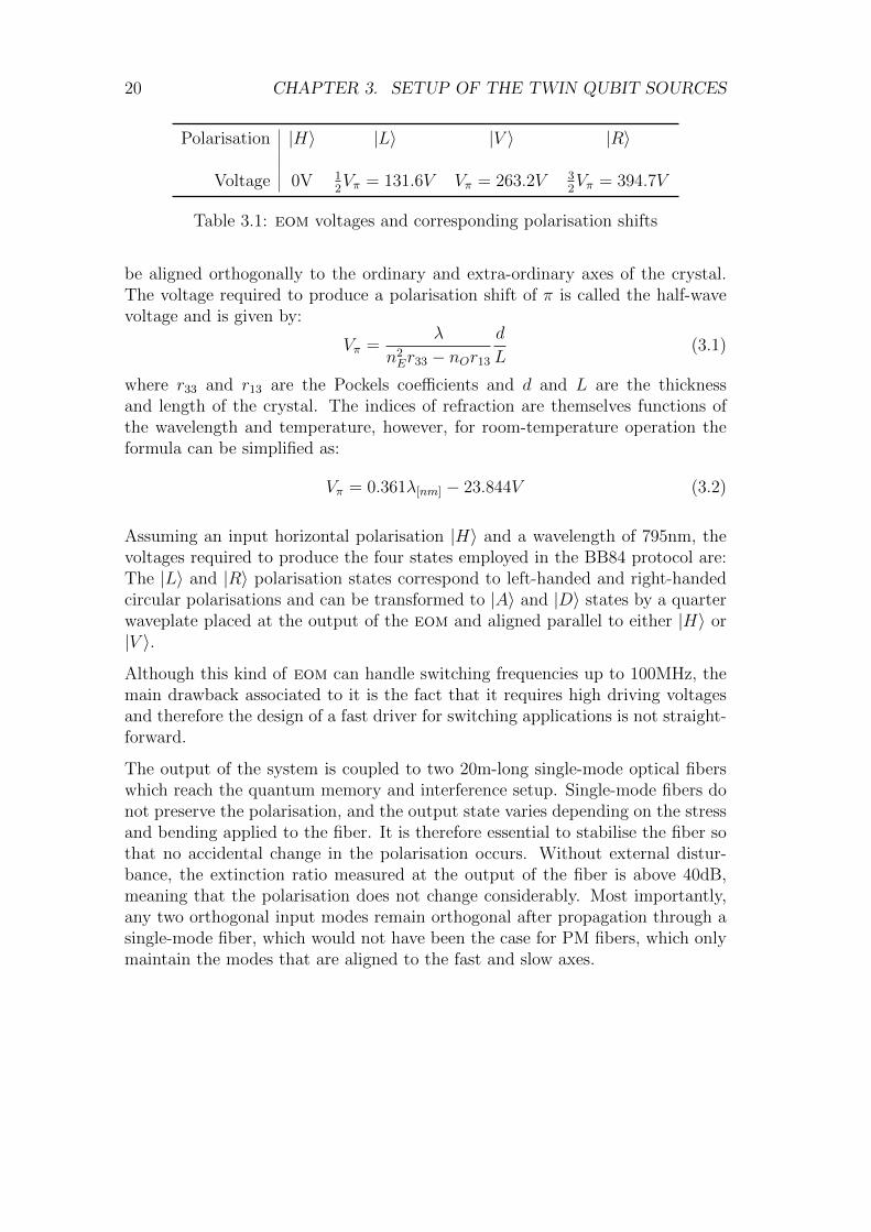
Polarisation |H〉 |L〉 |V 〉 |R〉
Voltage 0V 12Vπ = 131.6V Vπ = 263.2V 3
2Vπ = 394.7V
Table 3.1: eom voltages and corresponding polarisation shifts
be aligned orthogonally to the ordinary and extra-ordinary axes of the crystal.The voltage required to produce a polarisation shift of π is called the half-wavevoltage and is given by:
Vπ =λ
n2Er33 − nOr13
d
L(3.1)
where r33 and r13 are the Pockels coefficients and d and L are the thicknessand length of the crystal. The indices of refraction are themselves functions ofthe wavelength and temperature, however, for room-temperature operation theformula can be simplified as:
Vπ = 0.361λ[nm] − 23.844V (3.2)
Assuming an input horizontal polarisation |H〉 and a wavelength of 795nm, thevoltages required to produce the four states employed in the BB84 protocol are:The |L〉 and |R〉 polarisation states correspond to left-handed and right-handedcircular polarisations and can be transformed to |A〉 and |D〉 states by a quarterwaveplate placed at the output of the eom and aligned parallel to either |H〉 or|V 〉.
Although this kind of eom can handle switching frequencies up to 100MHz, themain drawback associated to it is the fact that it requires high driving voltagesand therefore the design of a fast driver for switching applications is not straight-forward.
The output of the system is coupled to two 20m-long single-mode optical fiberswhich reach the quantum memory and interference setup. Single-mode fibers donot preserve the polarisation, and the output state varies depending on the stressand bending applied to the fiber. It is therefore essential to stabilise the fiber sothat no accidental change in the polarisation occurs. Without external distur-bance, the extinction ratio measured at the output of the fiber is above 40dB,meaning that the polarisation does not change considerably. Most importantly,any two orthogonal input modes remain orthogonal after propagation through asingle-mode fiber, which would not have been the case for PM fibers, which onlymaintain the modes that are aligned to the fast and slow axes.
4Hong-Ou-Mandel interference with polarisation
qubits
4.1 Hong-Ou-Mandel interference
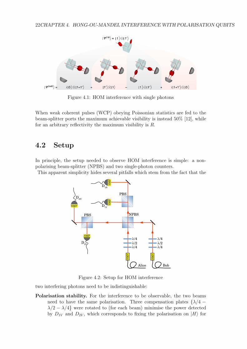
Hong-Ou-Mandel (HOM) interference is a quantum interference phenomenon firstobserved in 1987 [11] which occurs when two indistinguishable photons are fed totwo input ports of a 50:50 beam-splitter. HOM interference is fundamental forMDI-QKD applications.
With classical light, a beam-splitter acts as a power-splitter, by simply divid-ing the power at the two output ports by the ratio of transmissivity/reflectivityassociated to the beam-splitter. In the case of a single photon entering the beam-splitter, because of its indivisibility, the process becomes probabilistic and thephoton can either be reflected with probability R, or transmitted with probabil-ity (1−R), where R is the reflectivity of the beam-splitter.
For an input quantum state with a single photon at each port of a R:(1-R) beam-splitter,
ψIN = |1〉 ⊗ |1′〉 (4.1)
the output state is a quantum superposition of four possible cases, each weightedby their probability. In the case of reflection, the output state acquires an i factor.
ψOUT = R(1−R)i |0〉 ⊗ |1 + 1′〉 + R(1−R)i |0〉 |1 + 1′〉 ⊗ |0〉+ (1−R)(1−R) |1〉 ⊗ |1′〉 − R2 |1′〉 ⊗ |1〉
For a perfect 50:50 beam-splitter, if indeed the two photons |1〉 and |1′〉 are indis-tinguishable, the last two terms in ψOUT - corresponding to both photons beingeither reflected or transmitted - cancel out in destructive quantum interferenceand the two photons always exit the beam-splitter at the same port. This inter-ference can be measured by observing the coincidence between photons detectedat the two outputs. With indistinguishable single-photon Fock states the coinci-dence counts fall to zero and the visibility of the HOM dip is 100%.
21
22CHAPTER 4. HONG-OU-MANDEL INTERFERENCEWITH POLARISATIONQUBITS
Figure 4.1: HOM interference with single photons
When weak coherent pulses (WCP) obeying Poissonian statistics are fed to thebeam-splitter ports the maximum achievable visibility is instead 50% [12], whilefor an arbitrary reflectivity the maximum visibility is R.
4.2 Setup
In principle, the setup needed to observe HOM interference is simple: a non-polarising beam-splitter (NPBS) and two single-photon counters.This apparent simplicity hides several pitfalls which stem from the fact that the
/4λ/2λ/2λ
/4λ
/4λ /4λ
NPBS
PBS
PBS
BobAlice
SMF
SMF
SMF
SMF
SMF
SMF
D1H
D1V
D2V
D2H
Figure 4.2: Setup for HOM interference
two interfering photons need to be indistinguishable:
Polarisation stability. For the interference to be observable, the two beamsneed to have the same polarisation. Three compensation plates λ/4 −λ/2 − λ/4 were rotated to (for each beam) minimise the power detectedby D1V and D2V , which corresponds to fixing the polarisation on |H〉 for
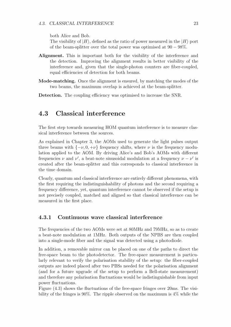
4.3. CLASSICAL INTERFERENCE 23
both Alice and Bob.The visibility of |H〉, defined as the ratio of power measured in the |H〉 portof the beam-splitter over the total power was optimised at 90− 98%.
Alignment. This is important both for the visibility of the interference andthe detection. Improving the alignment results in better visibility of theinterference and, given that the single-photon counters are fiber-coupled,equal efficiencies of detection for both beams.
Mode-matching. Once the alignment is ensured, by matching the modes of thetwo beams, the maximum overlap is achieved at the beam-splitter.
Detection. The coupling efficiency was optimised to increase the SNR.
4.3 Classical interference
The first step towards measuring HOM quantum interference is to measure clas-sical interference between the sources.
As explained in Chapter 3, the AOMs used to generate the light pulses outputthree beams with −ν, 0,+ν frequency shifts, where ν is the frequency modu-lation applied to the AOM. By driving Alice’s and Bob’s AOMs with differentfrequencies ν and ν ′, a beat-note sinusoidal modulation at a frequency ν − ν ′ iscreated after the beam-splitter and this corresponds to classical interference inthe time domain.
Clearly, quantum and classical interference are entirely different phenomena, withthe first requiring the indistinguishability of photons and the second requiring afrequency difference, yet, quantum interference cannot be observed if the setup isnot precisely coupled, matched and aligned so that classical interference can bemeasured in the first place.
4.3.1 Continuous wave classical interference
The frequencies of the two AOMs were set at 80MHz and 79MHz, so as to createa beat-note modulation at 1MHz. Both outputs of the NPBS are then coupledinto a single-mode fiber and the signal was detected using a photodiode.
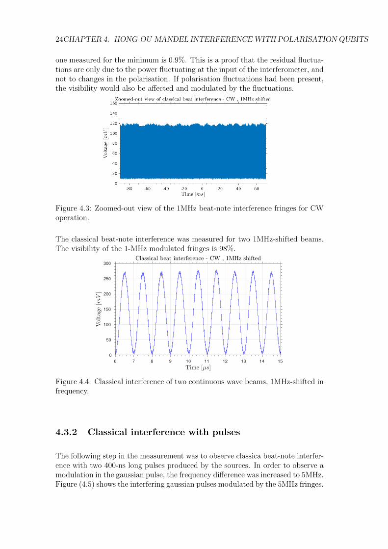
In addition, a removable mirror can be placed on one of the paths to direct thefree-space beam to the photodetector. The free-space measurement is particu-larly relevant to verify the polarisation stability of the setup: the fiber-coupledoutputs are indeed placed after two PBSs needed for the polarisation alignment(and for a future upgrade of the setup to perform a Bell-state measurement)and therefore any polarisation fluctuations would be indistinguishable from inputpower fluctuations.Figure (4.3) shows the fluctuations of the free-space fringes over 20ms. The visi-bility of the fringes is 90%. The ripple observed on the maximum is 4% while the
24CHAPTER 4. HONG-OU-MANDEL INTERFERENCEWITH POLARISATIONQUBITS
one measured for the minimum is 0.9%. This is a proof that the residual fluctua-tions are only due to the power fluctuating at the input of the interferometer, andnot to changes in the polarisation. If polarisation fluctuations had been present,the visibility would also be affected and modulated by the fluctuations.
Figure 4.3: Zoomed-out view of the 1MHz beat-note interference fringes for CWoperation.
The classical beat-note interference was measured for two 1MHz-shifted beams.The visibility of the 1-MHz modulated fringes is 98%.
6 7 8 9 10 11 12 13 14 15
0
50
100
150
200
250
300
Figure 4.4: Classical interference of two continuous wave beams, 1MHz-shifted infrequency.
4.3.2 Classical interference with pulses
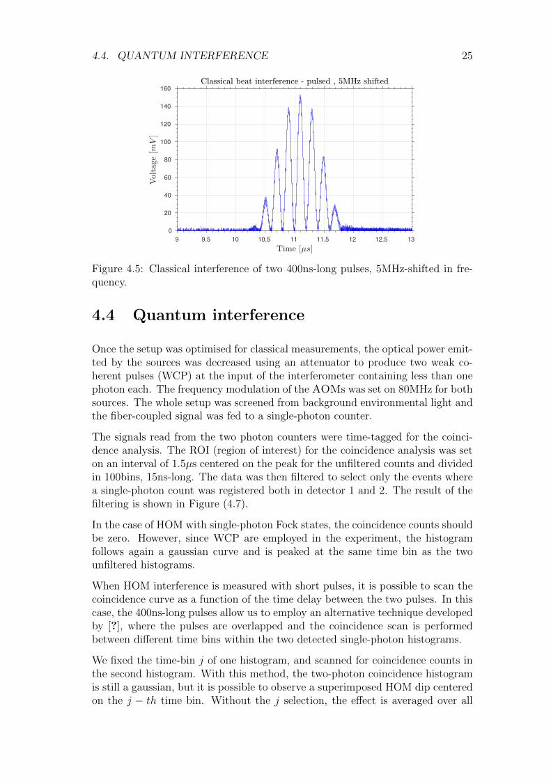
The following step in the measurement was to observe classica beat-note interfer-ence with two 400-ns long pulses produced by the sources. In order to observe amodulation in the gaussian pulse, the frequency difference was increased to 5MHz.Figure (4.5) shows the interfering gaussian pulses modulated by the 5MHz fringes.
4.4. QUANTUM INTERFERENCE 25
9 9.5 10 10.5 11 11.5 12 12.5 13
0
20
40
60
80
100
120
140
160
Figure 4.5: Classical interference of two 400ns-long pulses, 5MHz-shifted in fre-quency.
4.4 Quantum interference
Once the setup was optimised for classical measurements, the optical power emit-ted by the sources was decreased using an attenuator to produce two weak co-herent pulses (WCP) at the input of the interferometer containing less than onephoton each. The frequency modulation of the AOMs was set on 80MHz for bothsources. The whole setup was screened from background environmental light andthe fiber-coupled signal was fed to a single-photon counter.
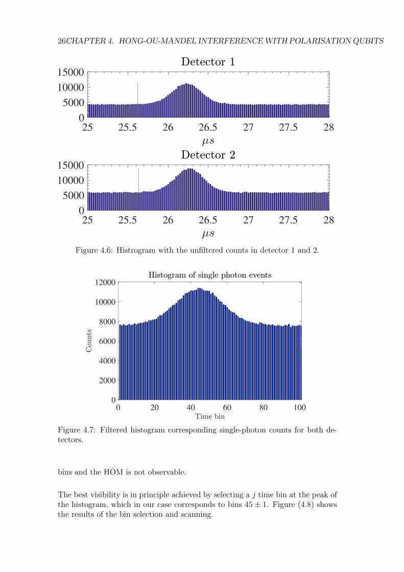
The signals read from the two photon counters were time-tagged for the coinci-dence analysis. The ROI (region of interest) for the coincidence analysis was seton an interval of 1.5µs centered on the peak for the unfiltered counts and dividedin 100bins, 15ns-long. The data was then filtered to select only the events wherea single-photon count was registered both in detector 1 and 2. The result of thefiltering is shown in Figure (4.7).
In the case of HOM with single-photon Fock states, the coincidence counts shouldbe zero. However, since WCP are employed in the experiment, the histogramfollows again a gaussian curve and is peaked at the same time bin as the twounfiltered histograms.
When HOM interference is measured with short pulses, it is possible to scan thecoincidence curve as a function of the time delay between the two pulses. In thiscase, the 400ns-long pulses allow us to employ an alternative technique developedby [?], where the pulses are overlapped and the coincidence scan is performedbetween different time bins within the two detected single-photon histograms.
We fixed the time-bin j of one histogram, and scanned for coincidence counts inthe second histogram. With this method, the two-photon coincidence histogramis still a gaussian, but it is possible to observe a superimposed HOM dip centeredon the j − th time bin. Without the j selection, the effect is averaged over all
26CHAPTER 4. HONG-OU-MANDEL INTERFERENCEWITH POLARISATIONQUBITS
25 25.5 26 26.5 27 27.5 28
0
5000
10000
15000
25 25.5 26 26.5 27 27.5 28
0
5000
10000
15000
Figure 4.6: Histrogram with the unfiltered counts in detector 1 and 2.
0 20 40 60 80 100
0
2000
4000
6000
8000
10000
12000
Figure 4.7: Filtered histogram corresponding single-photon counts for both de-tectors.
bins and the HOM is not observable.
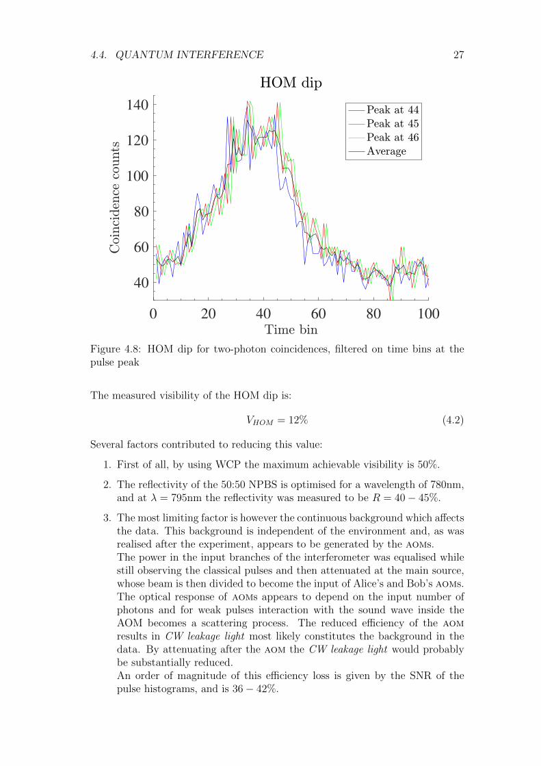
The best visibility is in principle achieved by selecting a j time bin at the peak ofthe histogram, which in our case corresponds to bins 45± 1. Figure (4.8) showsthe results of the bin selection and scanning.
4.4. QUANTUM INTERFERENCE 27
0 20 40 60 80 100
40
60
80
100
120
140
Figure 4.8: HOM dip for two-photon coincidences, filtered on time bins at thepulse peak
The measured visibility of the HOM dip is:
VHOM = 12% (4.2)
Several factors contributed to reducing this value:
1. First of all, by using WCP the maximum achievable visibility is 50%.
2. The reflectivity of the 50:50 NPBS is optimised for a wavelength of 780nm,and at λ = 795nm the reflectivity was measured to be R = 40− 45%.
3. The most limiting factor is however the continuous background which affectsthe data. This background is independent of the environment and, as wasrealised after the experiment, appears to be generated by the aoms.The power in the input branches of the interferometer was equalised whilestill observing the classical pulses and then attenuated at the main source,whose beam is then divided to become the input of Alice’s and Bob’s aoms.The optical response of aoms appears to depend on the input number ofphotons and for weak pulses interaction with the sound wave inside theAOM becomes a scattering process. The reduced efficiency of the aomresults in CW leakage light most likely constitutes the background in thedata. By attenuating after the aom the CW leakage light would probablybe substantially reduced.An order of magnitude of this efficiency loss is given by the SNR of thepulse histograms, and is 36− 42%.

28CHAPTER 4. HONG-OU-MANDEL INTERFERENCEWITH POLARISATIONQUBITS
In principle, all these effects have a multiplicative effect and the expected visibilityis:
V theorHOM = 50%⊗ 2R⊗ SNR = 16− 18% (4.3)
which is coherent with what is observed in the experiment.
5Storage and interference with quantum memory
After measuring the interference between the two pulses generated by the twosources, the setup was modified to include a quantum memory in the Alice chan-nel, before the interferometer.
5.1 Storage of pulses in a room-temperature quan-
tum memory
The 400-ns long pulses produced by Alice’s AOM are +80MHz shifted withrespect to the input laser and therefore the frequency lock of the control field hasto be adjusted to compensate for this shift and maintain the condition on thetwo-photon detuning δ = 0.
The storage was performed with classical pulses containing on average 108 pho-tons, so that the SNR ratio between probe and control field is high enough thatthe control field can be filtered without requiring the etalon setup, and the 40dBprovided by the output PBS are sufficient.
The adiabatic preparation of the atoms in the memory is achieved by varying thecontrol field power. The processi is composed of three stages: writing, storageand retrieval.
Writing. When the pulse arrives at the memory the control field is high andthe pulse is slowed down to the reduced group velocity vg, that arises fromEIT, and compressed in length to a factor of c/vg. In the case of our room-temperature Rb-vapour quantum memory, vg ∼ 105m/s and for 400ns-longpulses the pulse length is compressed from d = 120m to d ∼ 10cm which iscomparable to the size of the Rb-vapour cell (5cm).
Storage Immediately after the pulse enters the memory, the control field is re-duced to zero over a time interval of 10ns and as explained in Section (1.2.3)this creates a coherent transfer (mapping) of the amplitude from the probe
29
30CHAPTER 5. STORAGE AND INTERFERENCEWITHQUANTUMMEMORY
Figure 5.1: Cartoon representation of the storage process: (a) Time variation ofthe control field. (b) Storage under ideal conditions. (c) Realistic storage.
field to the collective spin excitation of the medium (the dark-state polari-ton). The amplitude of the spin excitation is proportional to the strengthof the control field, as per Eq. (1.15). The storage time is limited by thelifetime of the dark-state polariton. In other words, atomic coherence ispreserved in the medium until collisions and radiative decay prevail.
Retrieval The retrieval of the pulse is triggered by the control field. As thecontrol is turned back on, the coherence is transferred back from the spinwave to the probe field.
Under realistic conditions, the group velocity may not be sufficiently reduced byEIT to compress the whole probe pulse inside the medium, so that the front ofthe pulse escapes the cell before control field is turned off. Accordingly, the tailof the pulse may not be stored since it does not enter the medium during thewriting stage.Moreover, the bandwidth of the pulse should match the bandwidth of EIT whichis 1MHz.
Figure (5.2) shows the results obtained for the storage of pulses for intervalsvaried between 500ns and 2.9µs. The peak on the left represents the portion ofthe pulse which is slowed down but is unstored. The retrieved stored pulse is alsotruncated and the retrieval efficiency decays exponentially with increasing storagetime. This degradation is caused by decoherence of the atomic excitations whichresult in a reduced optical depth. The coherence time of the quantum memorywas estimated to be τ = 1µs. The Rb-vapour quantum memories studied in thiswork have been proved to be able to preserve the coherence and store pulses forτ = 40µs. The reason for the reduced coherence observed in this experiment ismost likely due to non-perfect EIT conditions in the cell, particularly, residualmagnetic fields and a non-uniform heating of the cell.
Temperature disomogeneities may cause the formation of rubidium condensationon the windows of the cell, which results in reduced visibility and efficiency.
5.2. PULSE INTERFERENCE WITH A QUANTUM MEMORY 31
0 0.5 1 1.5 2 2.5 3 3.5 4 4.5 5
-2
0
2
4
6
8
10
12
14
16
18
10-3
Figure 5.2: Retrieved pulse shape after different storage times. Decoherencecauses an exponential decay of the storage efficiency.
Figure 5.3: Picture showing the Rb con-densation on the window of a vapourcell. In order to eliminate the condesa-tion, the cell has to be removed from thequantum memory and placed on a spe-cial heater: repeated slow heating cy-cles at 70−80C regenerate the cell andeliminate the condensation.
5.2 Pulse interference with a quantum memory
The first step towards realising MA-MDI-QKD is to demonstrate that it is pos-sible to use the quantum memory in one channel to match for delays introducedin the other channel and measure interference between the stored pulse and thedelayed pulse.
In the following experiment, one pulse was stored in the quantum memory, whilethe other was sent directly from the source to the interferometer. The unstoredpulse was delayed and shifted in frequency to observe classical beat-note interfer-ence between the stored and unstored pulses.
Figure (5.5) shows the effect of the control field on the interference. Without
32CHAPTER 5. STORAGE AND INTERFERENCEWITHQUANTUMMEMORY
0.01 0.0100004 0.0100008 0.0100012 0.0100016
-2
-1
0
1
2
3
4
5
6
7
810
-3
Figure 5.4: Storage of classical 400ns-long pulses for 10µs under optimal condi-tions: both polarisations are stored with the same efficiency
0 0.5 1 1.5 2 2.5 3 3.5 4
-2
0
2
4
6
8
10
1210
-3
Figure 5.5: Interference of classical 400ns-long stored and delayed pulses, 9MHz-shifted in frequency, after storage for 1µs
EIT and modulation of the control field, the two pulses produced by the sources(in red in the graph), do not overlap and no interference can be observed. Bymodulating the control field, instead, it is possible to match the storage timeof the memory to the 1µs delay introduced in the other channel and beat-noteinterference fringes appear. The same measurement was performed by varyingthe frequency difference and storage time and Figure (5.6) shows the result for a
5.2. PULSE INTERFERENCE WITH A QUANTUM MEMORY 33
0 0.5 1 1.5 2 2.5 3 3.5 4
-2
0
2
4
6
8
10
12
10-3
Figure 5.6: Interference of classical 400ns-long stored and delayed pulses afterstorage for 1.9µs
storage time of 1.9µs and frequency difference of 2MHz. Despite the weak signal,the interference still exhibits a visibility above 70%.

34CHAPTER 5. STORAGE AND INTERFERENCEWITHQUANTUMMEMORY
6Setup for the random polarisation qubit source
In order to perform the storage and interference of pulses, the polarisation couldbe manually varied by applying the appropriate high voltage to the eoms througha DC power supply and HV amplifier. For MDI-QKD applications, however,the twin sources’ eoms should be driven independently to produce a randompolarisation modulation with a switching frequency equal to the repetition rateof the pulses produced by the aoms.
In this Chapter, I will present the design and implementation of a high-voltageswitching circuit, together with the development of the digital interface, imple-mented on an fpga, which is needed to produce the triggers for the four voltagelevels of the eom driver, for the aom and for the detectors.
6.1 Design and implementation of a driver cir-
cuit for the EOM
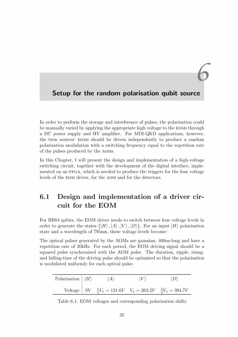
For BB84 qubits, the EOM driver needs to switch between four voltage levels inorder to generate the states |H〉 , |A〉 , |V 〉 , |D〉. For an input |H〉 polarisationstate and a wavelength of 795nm, these voltage levels become:
The optical pulses generated by the AOMs are gaussian, 400ns-long and have arepetition rate of 20kHz. For each period, the EOM driving signal should be asquared pulse synchronised with the AOM pulse. The duration, ripple, rising-and falling-time of the driving pulse should be optimised so that the polarisationis modulated uniformly for each optical pulse.
Polarisation |H〉 |A〉 |V 〉 |D〉
Voltage 0V 12Vπ = 131.6V Vπ = 263.2V 3
2Vπ = 394.7V
Table 6.1: EOM voltages and corresponding polarisation shifts
35
36CHAPTER 6. SETUP FOR THE RANDOMPOLARISATION QUBIT SOURCE
6.1.1 General idea of the design
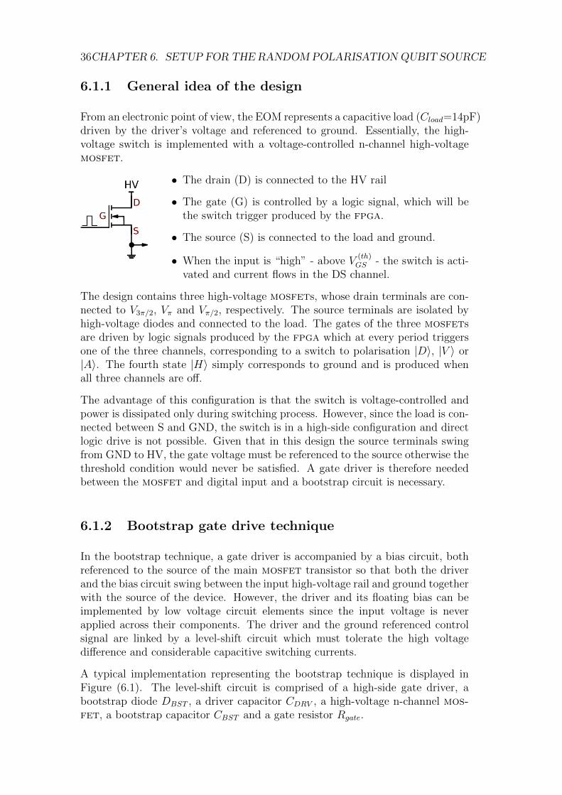
From an electronic point of view, the EOM represents a capacitive load (Cload=14pF)driven by the driver’s voltage and referenced to ground. Essentially, the high-voltage switch is implemented with a voltage-controlled n-channel high-voltagemosfet.
• The drain (D) is connected to the HV rail
• The gate (G) is controlled by a logic signal, which will bethe switch trigger produced by the fpga.
• The source (S) is connected to the load and ground.
• When the input is “high” - above V(th)GS - the switch is acti-
vated and current flows in the DS channel.
The design contains three high-voltage mosfets, whose drain terminals are con-nected to V3π/2, Vπ and Vπ/2, respectively. The source terminals are isolated byhigh-voltage diodes and connected to the load. The gates of the three mosfetsare driven by logic signals produced by the fpga which at every period triggersone of the three channels, corresponding to a switch to polarisation |D〉, |V 〉 or|A〉. The fourth state |H〉 simply corresponds to ground and is produced whenall three channels are off.
The advantage of this configuration is that the switch is voltage-controlled andpower is dissipated only during switching process. However, since the load is con-nected between S and GND, the switch is in a high-side configuration and directlogic drive is not possible. Given that in this design the source terminals swingfrom GND to HV, the gate voltage must be referenced to the source otherwise thethreshold condition would never be satisfied. A gate driver is therefore neededbetween the mosfet and digital input and a bootstrap circuit is necessary.
6.1.2 Bootstrap gate drive technique
In the bootstrap technique, a gate driver is accompanied by a bias circuit, bothreferenced to the source of the main mosfet transistor so that both the driverand the bias circuit swing between the input high-voltage rail and ground togetherwith the source of the device. However, the driver and its floating bias can beimplemented by low voltage circuit elements since the input voltage is neverapplied across their components. The driver and the ground referenced controlsignal are linked by a level-shift circuit which must tolerate the high voltagedifference and considerable capacitive switching currents.
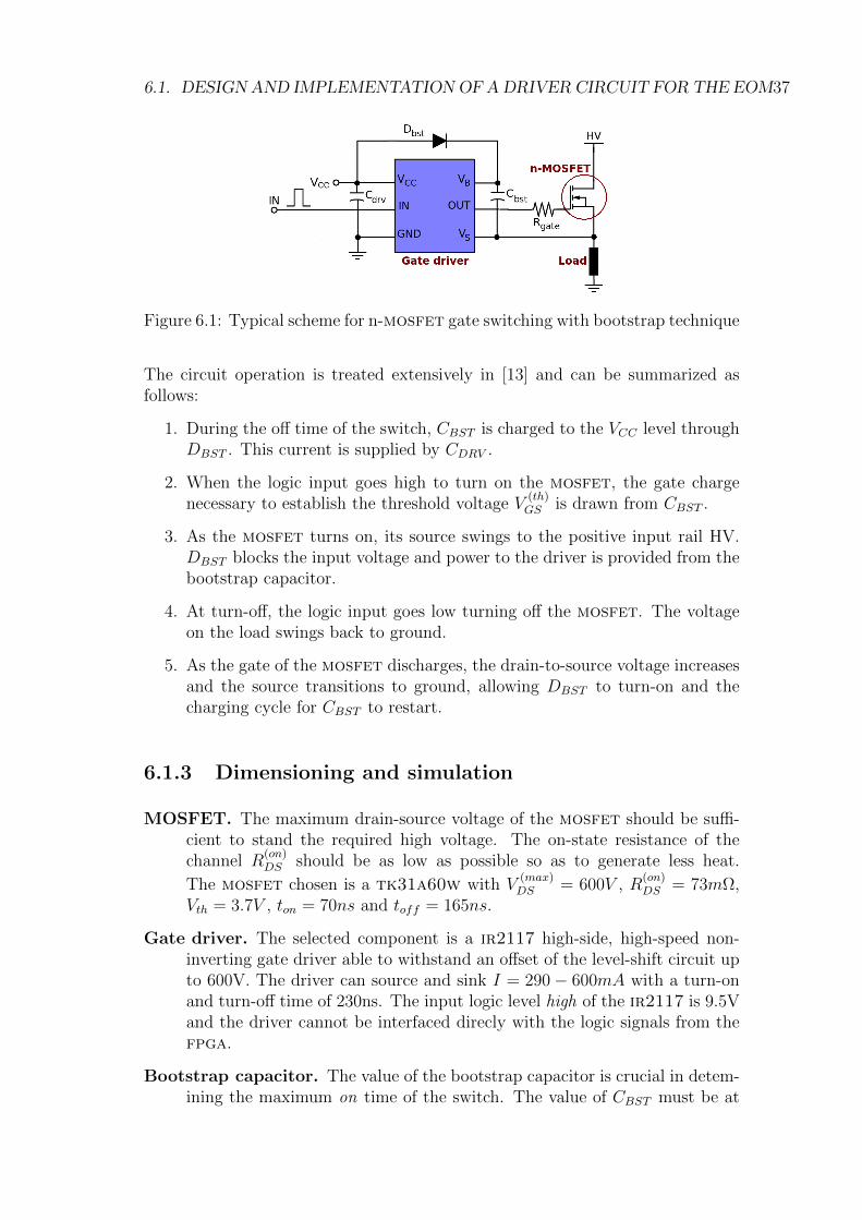
A typical implementation representing the bootstrap technique is displayed inFigure (6.1). The level-shift circuit is comprised of a high-side gate driver, abootstrap diode DBST , a driver capacitor CDRV , a high-voltage n-channel mos-fet, a bootstrap capacitor CBST and a gate resistor Rgate.
6.1. DESIGN AND IMPLEMENTATION OF ADRIVER CIRCUIT FOR THE EOM37
Figure 6.1: Typical scheme for n-mosfet gate switching with bootstrap technique
The circuit operation is treated extensively in [13] and can be summarized asfollows:
1. During the off time of the switch, CBST is charged to the VCC level throughDBST . This current is supplied by CDRV .
2. When the logic input goes high to turn on the mosfet, the gate chargenecessary to establish the threshold voltage V
(th)GS is drawn from CBST .
3. As the mosfet turns on, its source swings to the positive input rail HV.DBST blocks the input voltage and power to the driver is provided from thebootstrap capacitor.
4. At turn-off, the logic input goes low turning off the mosfet. The voltageon the load swings back to ground.
5. As the gate of the mosfet discharges, the drain-to-source voltage increasesand the source transitions to ground, allowing DBST to turn-on and thecharging cycle for CBST to restart.
6.1.3 Dimensioning and simulation
MOSFET. The maximum drain-source voltage of the mosfet should be suffi-cient to stand the required high voltage. The on-state resistance of thechannel R
(on)DS should be as low as possible so as to generate less heat.
The mosfet chosen is a tk31a60w with V(max)DS = 600V , R
(on)DS = 73mΩ,
Vth = 3.7V , ton = 70ns and toff = 165ns.
Gate driver. The selected component is a ir2117 high-side, high-speed non-inverting gate driver able to withstand an offset of the level-shift circuit upto 600V. The driver can source and sink I = 290− 600mA with a turn-onand turn-off time of 230ns. The input logic level high of the ir2117 is 9.5Vand the driver cannot be interfaced direcly with the logic signals from thefpga.
Bootstrap capacitor. The value of the bootstrap capacitor is crucial in detem-ining the maximum on time of the switch. The value of CBST must be at
38CHAPTER 6. SETUP FOR THE RANDOMPOLARISATION QUBIT SOURCE
least:
CBST =QCB
∆VCB=QG + ton · IB
∆VCB(6.1)
where IB = 400µA is the supply bias current of the ir2117 and∆VCB =1%VCC = 0.15V is the maximum allowable voltage ripple. For ton = 2µsCBST & 700n and a value CBST = 1µF as chosen.
Driver capacitor. As a rule of thumb, the driver capacitor must satisfy CDRV ∼10 · CBST and CDRV = 10µF.
Gate resistor. The purpose of the gate resisitor is to dampen any oscillationsin the output of the gate driver. The optimal value was calculated to beRgate = 62Ω.
Bootstrap and output diodes. The voltage rating of DBST and DOUT mustbe sufficiently high to stand-off the high-side mosfet drain voltage anda current rating greater than or equal to the maximum average current atswitching. It must also have a sufficiently fast reverse-recovery time to avoidmomentarily sourcing current from the high-voltage drain supply into thelower voltage VCC supply.
Pull-down resistor. A 10Ω resistor is placed between the output to the eomand ground to create a discharge path for the eom when all switches areoff.
HV DC-DC converter The high-voltage is supplied by a DC-DC converter,which for ann input voltage of 12V produces an output voltage of 500V,whichis then divided to produce V3π/2 , Vπ and Vπ/2. The output current of 20mAis not sufficient for switching the load, therefore a 1µF storage capacitoris placed between each drain and ground and acts a charge reservoir forswitching.
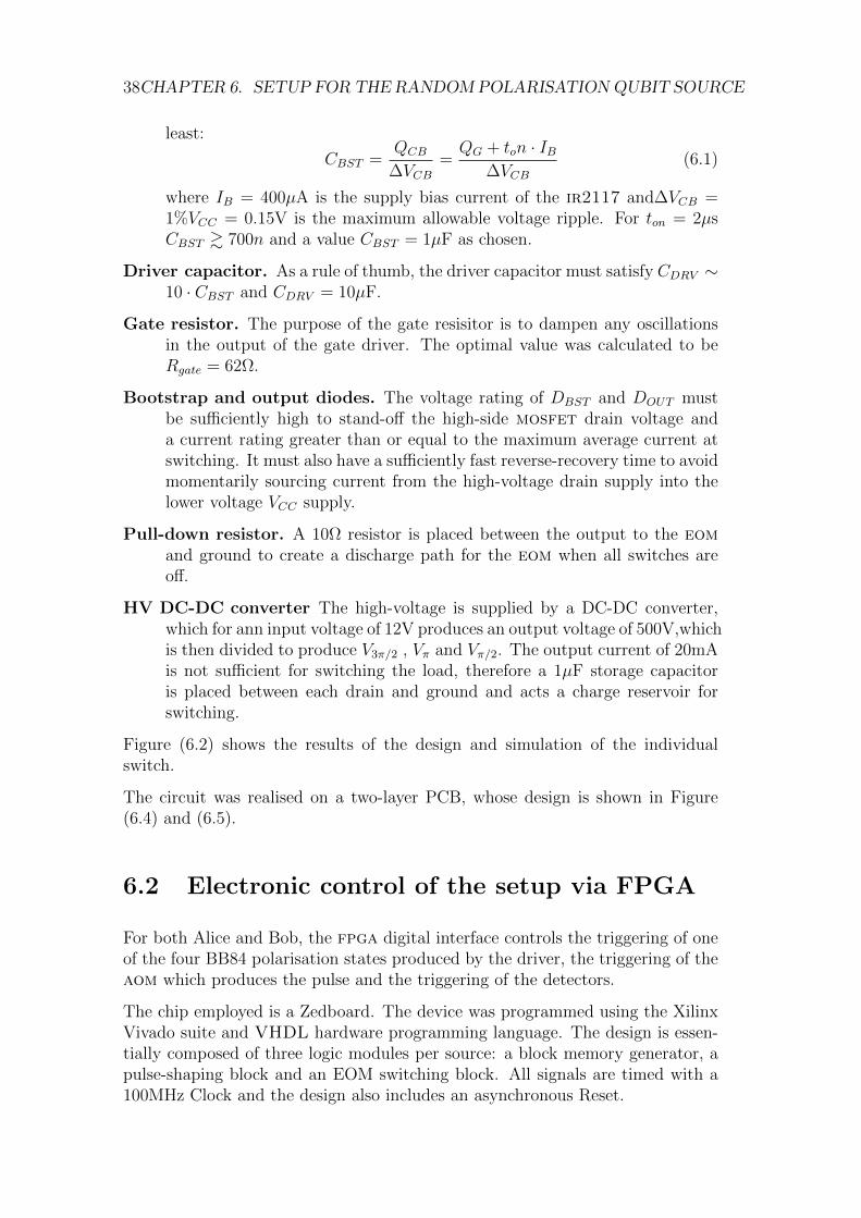
Figure (6.2) shows the results of the design and simulation of the individualswitch.
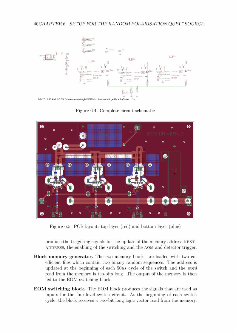
The circuit was realised on a two-layer PCB, whose design is shown in Figure(6.4) and (6.5).
6.2 Electronic control of the setup via FPGA
For both Alice and Bob, the fpga digital interface controls the triggering of oneof the four BB84 polarisation states produced by the driver, the triggering of theaom which produces the pulse and the triggering of the detectors.
The chip employed is a Zedboard. The device was programmed using the XilinxVivado suite and VHDL hardware programming language. The design is essen-tially composed of three logic modules per source: a block memory generator, apulse-shaping block and an EOM switching block. All signals are timed with a100MHz Clock and the design also includes an asynchronous Reset.
6.2. ELECTRONIC CONTROL OF THE SETUP VIA FPGA 39
(a) Circuit schematic of one of the three parallel switches.
(b) Simulated square pulses: input VIN = 10V (red), MOSFET gate signal Vgate =HV + Vcc (green) and output signal Vout = HV (blue).
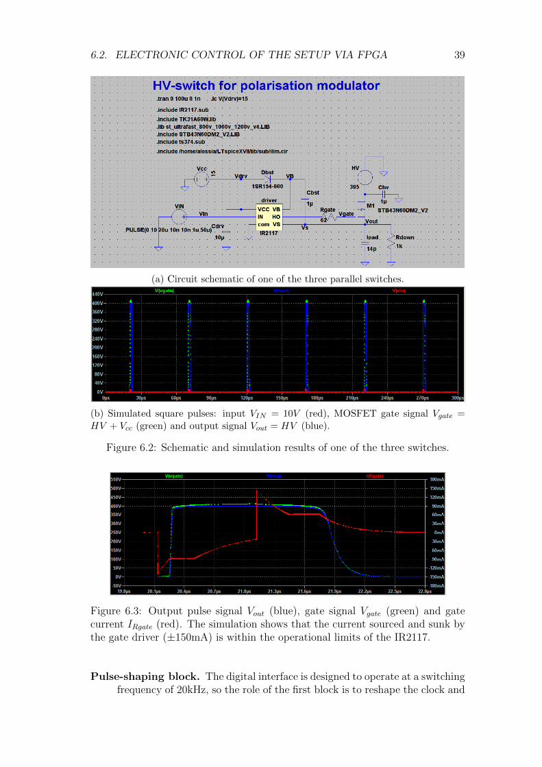
Figure 6.2: Schematic and simulation results of one of the three switches.
Figure 6.3: Output pulse signal Vout (blue), gate signal Vgate (green) and gatecurrent IRgate (red). The simulation shows that the current sourced and sunk bythe gate driver (±150mA) is within the operational limits of the IR2117.
Pulse-shaping block. The digital interface is designed to operate at a switchingfrequency of 20kHz, so the role of the first block is to reshape the clock and
40CHAPTER 6. SETUP FOR THE RANDOMPOLARISATION QUBIT SOURCE
9/9/1711:13AMf=0.55/home/alessia/eagle/NEW-circuit/schematic_4lHV.sch(Sheet:1/1)
SpiceO
rder1
SpiceO
rder2
SpiceO
rder1
SpiceO
rder2
SpiceO
rder1
SpiceO
rder2
SpiceO
rder1
SpiceO
rder2
SpiceOrder1SpiceOrder2
SpiceOrder1SpiceOrder2
SpiceOrder1SpiceOrder2
SpiceOrder1 SpiceOrder2
SpiceOrder1 SpiceOrder2
SpiceOrder1 SpiceOrder2
GND
60Ohm
GND
60Ohm
GND
GND
60Ohm
GND
GND
GND
GND
GND
IRF520IRF520
IRF520
10uF
10uF1uF
10uF
1uF
1uF
1uF1uF
GND
GND 10uF
GND
22K
GND
GNDGND
1k
4.7k
GND
4.7k
4.7k
MUR440R
LMUR440R
L
MUR440R
L
MUR440R
L
MUR440RLMUR440RL
MUR440RL
1N4004
GND1N4004
GND1N4004
GND
SMA-142-0701-871/880
SMA-142-0701-871/880
SMA-142-0701-871/880
SMA-142-0701-871/880
SSW-104-02-S-Q SSW-104-02-S-QSSW-104-02-S-Q
SK129
SK129
SK129
EMCO_FS05
GND
RGATE3RGATE2
RGATE1Q1
Q2Q3
C_D
RV3
C_BST3C_BST2
C_D
RV2
C_BST1
CHIN1
CHIN2
CHIN3
C_D
RV1
R_LOAD
H_0
H3_3
H3_2
H3_1
DOUT_
F
DOUT_
3
DOUT_
2
DOUT_
1
DBST_1DBST_2
DBST_3
DIN_1
DIN_2
DIN_3
TTL1
TTL2
TTL3
OUT
GATE3-1
GATE3-2GATE3-3
GATE3-4
GATE3-5
GATE3-6GATE3-7GATE3-8
GATE1-1
GATE1-2GATE1-3
GATE1-4
GATE1-5
GATE1-6 GATE1-7GATE1-8
GATE2-1
GATE2-2GATE2-3
GATE2-4
GATE2-5
GATE2-6 GATE2-7GATE2-8
KK1
KK3
KK4
EMCOFS05+VININ+
-VININ-
+VOUT OUT+COM CT
-VOUT OUT-
R1
31
2
HVPOWER12
VCC12
V_OUT
VS1
VS1
VS3
VS3
VS2VS2
VS2
12V
12V
TTL1
TTL1
TTL2
TTL2
TTL3
TTL3
VCC
VCC VCC
VCC
HV2
HV2
HV1
HV1
HV3
HV3
DC/DCCONVERTER
Figure 6.4: Complete circuit schematic
Figure 6.5: PCB layout: top layer (red) and bottom layer (blue)
produce the triggering signals for the update of the memory address next-address, the enabling of the switching and the aom and detector trigger.
Block memory generator. The two memory blocks are loaded with two co-efficient files which contain two binary random sequences. The address isupdated at the beginning of each 50µs cycle of the switch and the wordread from the memory is teo-bits long. The output of the memory is thenfed to the EOM-switching block.
EOM switching block. The EOM block produces the signals that are used asinputs for the four-level switch circuit. At the beginning of each switchcycle, the block receives a two-bit long logic vector read from the memory.
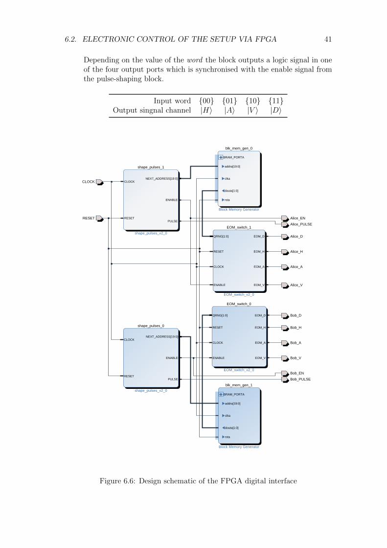
6.2. ELECTRONIC CONTROL OF THE SETUP VIA FPGA 41
Depending on the value of the word the block outputs a logic signal in oneof the four output ports which is synchronised with the enable signal fromthe pulse-shaping block.
Input word 00 01 10 11Output singnal channel |H〉 |A〉 |V 〉 |D〉
blk_mem_gen_0
Block Memory Generator
BRAM_PORTA
addra[19:0]
clka
douta[1:0]
rsta
CLOCK
shape_pulses_1
shape_pulses_v2_0
CLOCK
RESET
NEXT_ADDRESS[19:0]
ENABLE
PULSERESET Alice_EN
Alice_PULSE
Alice_D
Alice_H
EOM_switch_1
EOM_switch_v2_0
QRNG[1:0]
RESET
CLOCK
ENABLE
EOM_D
EOM_H
EOM_A
EOM_V
Alice_A
Alice_V
Bob_D
Bob_H
EOM_switch_0
EOM_switch_v2_0
QRNG[1:0]
RESET
CLOCK
ENABLE
EOM_D
EOM_H
EOM_A
EOM_V
Bob_A
shape_pulses_0
shape_pulses_v2_0
CLOCK
RESET
NEXT_ADDRESS[19:0]
ENABLE
PULSE
Bob_V
Bob_EN
Bob_PULSE
blk_mem_gen_1
Block Memory Generator
BRAM_PORTA
addra[19:0]
clka
douta[1:0]
rsta
Figure 6.6: Design schematic of the FPGA digital interface

42CHAPTER 6. SETUP FOR THE RANDOMPOLARISATION QUBIT SOURCE
7Summary and outlook
7.1 Summary
- In this thesis, I described the theory and operation of Rb-vapour room-temperature quantum memories and their applications in quantum com-munication.
- I set up two twin polarisation qubit sources which employ acousto-opticmodulators (aoms) for pulsing and electro-optic modulators (eoms) forpolarisation switching.
- I set up an interferometer to measure both classical and quantum interfer-ence.
- I observed classical beat-note interference both with continuous waves andpulses.
- I measured Hong-Ou-Mandel two-photon interference between two weakcoherent pulses produced by the sources, observing a HOM dip visibility of12%.
- I measured the characteristics of pulses stored in the quantum memory,particularly varying the storage time between 500ns− 2.8µs.
- I measured classical interference between a pulse stored in a quantum mem-ory and a pulse delayed at the source.
- I designed a 4-level high-voltage switch to be used as a driver for the eoms,and programmed an fpga to be used as a digital interface for the twodrivers, the two aoms and the detection setup.
- As a preliminary work, I studied and measured the propagation propertiesof vortex beams carrying orbital angular momentum produced by q-plates,their intensity distribution and wavefront.
43
44 CHAPTER 7. SUMMARY AND OUTLOOK
7.2 Outlook
The results presented in this thesis are a first step towards the integration of a Rb-vapour room-temperature quantum memory in a measurement-device-independentquantum key-distribution scheme to perform MA-MDI-QKD.
The QuantumFuture group in Padova and the QIT group in Stony Brook planto extend the collaboration, and I will continue working on this project as a PhDstudent in the QuantumFuture group.
In this respect, this thesis is a work-in-progress and many improvements andupgrades are possible and planned.
- A second quantum memory will be implemented in the channel which, forthis first experiment, was only delayed, so as to achieve fine control on theoverlap of the pulses and timing of the interference.
- The coherence (i.e. storage) time of the quantum memories is consider-ably improved by using paraffin-coated cells, where the dephasing due tocollisions is reduced.
- Two extra detectors will be added to the interference setup to perform acomplete Bell-state measurement.
- Once the setup is optimised for single-photon operation, a crucial exper-iment before the realisation of MA-MDI-QKD will be HOM interferencewith two quantum memories.
- As for the random qubit sources needed for the QKD experiment, the cus-tom high-voltage electronics designed for driving the eoms is delicate andcannot handle switching frequencies higher that 30kHz. A more robust so-lution, yet more expensive, would be to design a custom low-voltage switch,and interface it with a high-voltage amplifier to achieve the correct drivingvoltages for the eom.
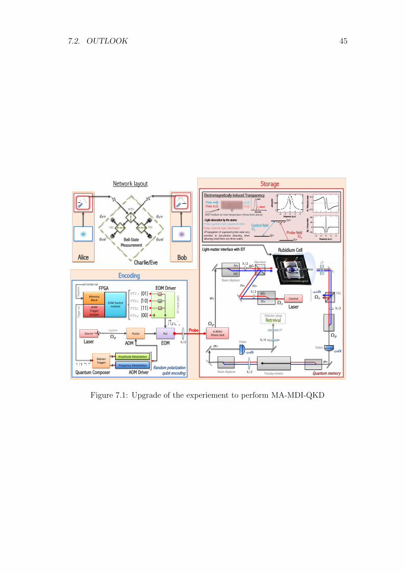
7.2. OUTLOOK 45
0110100110
MemoryBlock
AOMTriggermodule
EOMSwitchmodule
FPGA EOM Driver
Storage
Laser
Pulser Pol.
AOM EOM
Quantum Composer
MasterTrigger
AmplitudeModula8on
FrequencyModula8on
Encoding
795nm
TTL 1
TTL2TTL3 TTL4
HV 3
-leve
l swi
tch
Trig
ger o
ut
Sequ
ence
AOM Driver
Source
Random polarization qubit encoding
λ/2
Ω Probe
p
Network layout
Bell-State Measurement
Charlie/Eve Alice Bob
D1H
D1V
D2H
D2V
NPBS
PBS PBS
6.8GHzPhase-lock
Quantum memory
|P>
Light-matter interface with EIT
|V>|V>Beam displacer
Glan-laser |H>
λ/2
Rubidium Cell
λ/2
ControlΩ c
Laser
LP
-42dB
Retreival
|H>
|V>
|H>
|V>Ω c
Ω p
PBS
|P>
Ω p
λ/2 Faraday Isolator
Etalon
Etalon
-50dB-50dB
|P>
λ/4
LP
Detector setup
Beam displacer
λ/2
Control field
Probe field
|2>
|3>|1>
wLight absorption by the atoms: Probe: quantum state (squeezed state) Pump: coherent state (ideal laser) wPropagation of squeezed probe state very sensitive to two-photon detuning, when detuning small there are three scales. frequency (a.u.)
Ng-1
Gro
up in
dex
N-1
Refra
ction
inde
x Electromagnetically-Induced Transparency
abso
rptio
n
frequency (a.u.) Rb87 medium at room temperature (three-level atoms)
Pump Probe
Ω p
Ω c
input
delayed
time (ms)
80
40
0
-40
-4 -2 0 2 4
-0.5
0
0.5
80
40
0
-40
-4 -2 0 2 4
Figure 7.1: Upgrade of the experiement to perform MA-MDI-QKD

46 CHAPTER 7. SUMMARY AND OUTLOOK
AStudy of orbital angular momentum states
A.1 OAM states for Quantum Communication
Orbital angular momentum (OAM), together with spin angular momentum (SAM),is an intrinsic property of light. From a classical point of view, in the paraxiallimit the two components can be readily associated to different properties of theoptical beam: the SAM is associated with the beam’s circular polarization contentwhile the OAM is associated with the helical structure of the optical wavefrontaround the beam axis and with an optical vortex located on the beam axis.
The main motivation for the study of OAM states for quantum information andquantum communication applications arises from the fact that the OAM value isindependent of the choice of coordinates and therefore, unlike polarisation encod-ing, transmitter and receiver are not required to precisely align their references.Moreover, whereas the photon’s SAM can only take two values, Sz = ±, thevalue of OAM per photon can assume any integer value multiple of :
Lz = ±m (A.1)
The OAM unit m also defines the phase variation of the wavefront, described bythe m-fold helix exp(imϕ), where ϕ is the azimuthal angle in the plane orthogonalto the propagation axis. This higher dimensionality of the OAM states allows toencode information in qudits, i.e., qubits of dimension d.
OAM states have already been used to realise free-space QKD links [14], but un-fortunately, due to their higher divergence, the maximum distance of the channelis constrained to a few km. As explained in Section ??, it is also more difficultto correct any aberrations and distortions induced on the wavefront of an OAMbeam by atmospheric turbulence.
An interesting perspective would open from the study of the storage of OAMstates in a quantum memory. As explained in the following section, OAM beamscan be produced by conversion from SAM states, in a process called spin-to-orbital-conversion (STOC). This transformation is unitary and can therefore bereversed to re-obtain a SAM state with a fidelity as high as 98% [15].
47
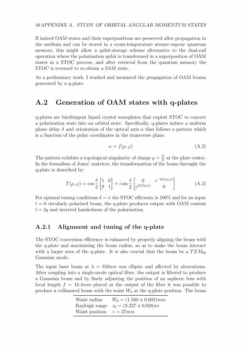
48APPENDIX A. STUDY OF ORBITAL ANGULAR MOMENTUM STATES
If indeed OAM states and their superpositions are preserved after propagation inthe medium and can be stored in a room-temperature atomic-vapour quantummemory, this might allow a qubit-storage scheme alternative to the dual-railoperation where the polarisation qubit is transformed in a superposition of OAMstates in a STOC process, and after retrieval from the quantum memory theSTOC is reversed to re-obtain a SAM state.
As a preliminary work, I studied and measured the propagation of OAM beamsgenerated by a q-plate.
A.2 Generation of OAM states with q-plates
q-plates are birefringent liquid crystal waveplates that exploit STOC to converta polarisation state into an orbital state. Specifically, q-plates induce a uniformphase delay δ and orientation of the optical axis α that follows a pattern whichis a function of the polar coordinates in the transverse plane.
α = f(ρ, ϕ) (A.2)
The pattern exhibits a topological singularity of charge q = |l|2
at the plate center.In the formalism of Jones’ matrices, the transformation of the beam throught theq-plate is described by:
T (ρ, ϕ) = cosδ
2
[1 00 1
]+ i sin
δ
2
[0 e−2if(ρ,ϕ)
e2if(ρ,ϕ) 0
](A.3)
For optimal tuning conditions δ = π the STOC efficienty is 100% and for an inputl = 0 circularly polarised beam, the q-plate produces output with OAM contentl = 2q and inverted handedness of the polarization.
A.2.1 Alignment and tuning of the q-plate
The STOC conversion efficiency is enhanced by properly aligning the beam withthe q-plate and maximising the beam radius, so as to make the beam interactwith a larger area of the q-plate. It is also crucial that the beam be a TEM00
Gaussian mode.
The input laser beam at λ = 850nm was elliptic and affected by aberrations.After coupling into a single-mode optical fiber, the output is filtered to producea Gaussian beam and by finely adjusting the position of an aspheric lens withfocal length f = 18.4mm placed at the output of the fiber it was possible toproduce a collimated beam with the waist W0 at the q-plate position. The beam
Waist radius W0 = (1.580± 0.002)mmRayleigh range z0 = (9.227± 0.028)mWaist position z = 27mm
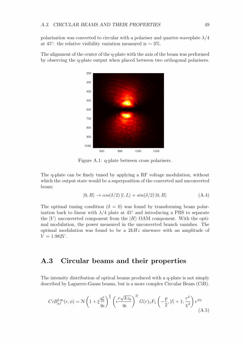
A.3. CIRCULAR BEAMS AND THEIR PROPERTIES 49
polarisation was converted to circular with a polariser and quarter-waveplate λ/4at 45: the relative visibility variation measured is ∼ 3%.
The alignment of the center of the q-plate with the axis of the beam was performedby observing the q-plate output when placed between two orthogonal polarisers.
Figure A.1: q-plate between cross polarisers.
The q-plate can be finely tuned by applying a RF voltage modulation, withoutwhich the output state would be a superposition of the converted and unconvertedbeam:
|0, R〉 → cos(δ/2) |l, L〉+ sin(δ/2) |0, R〉 (A.4)
The optimal tuning condition (δ = 0) was found by transforming beam polar-ization back to linear with λ/4 plate at 45 and introducing a PBS to separatethe |V 〉 unconverted component from the |H〉 OAM component. With the opti-mal modulation, the power measured in the unconverted branch vanishes. Theoptimal modulation was found to be a 2kHz sinewave with an amplitude ofV = 1.982V .
A.3 Circular beams and their properties
The intensity distribution of optical beams produced with a q-plate is not simplydescribed by Laguerre-Gauss beams, but is a more complex Circular Beam (CiB).
CiBξ,q0p,l (r, φ) = N
(1 + ξ
q∗0q0
) p2(ir√kz0
q0
)|l|G(r)1F1
(−p
2, |l|+ 1;
r2
χ2
)eilφ
(A.5)
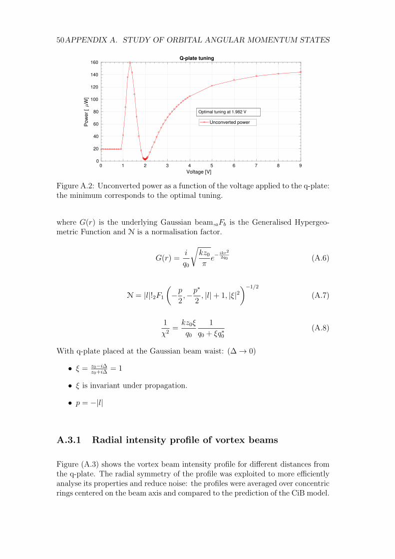
50APPENDIX A. STUDY OF ORBITAL ANGULAR MOMENTUM STATES
0 1 2 3 4 5 6 7 8 9
Voltage [V]
0
20
40
60
80
100
120
140
160
Pow
er
[W
]
Q-plate tuning
Unconverted power
Optimal tuning at 1.982 V
Figure A.2: Unconverted power as a function of the voltage applied to the q-plate:the minimum corresponds to the optimal tuning.
where G(r) is the underlying Gaussian beam,aFb is the Generalised Hypergeo-metric Function and N is a normalisation factor.
G(r) =i
q0
√kz0
πe− ikr2
2q0 (A.6)
N = |l|!2F1
(−p
2,−p
∗
2, |l|+ 1, |ξ|2
)−1/2
(A.7)
1
χ2=kz0ξ
q0
1
q0 + ξq∗0(A.8)
With q-plate placed at the Gaussian beam waist: (∆→ 0)
• ξ = z0−i∆z0+i∆
= 1
• ξ is invariant under propagation.
• p = −|l|
A.3.1 Radial intensity profile of vortex beams
Figure (A.3) shows the vortex beam intensity profile for different distances fromthe q-plate. The radial symmetry of the profile was exploited to more efficientlyanalyse its properties and reduce noise: the profiles were averaged over concentricrings centered on the beam axis and compared to the prediction of the CiB model.
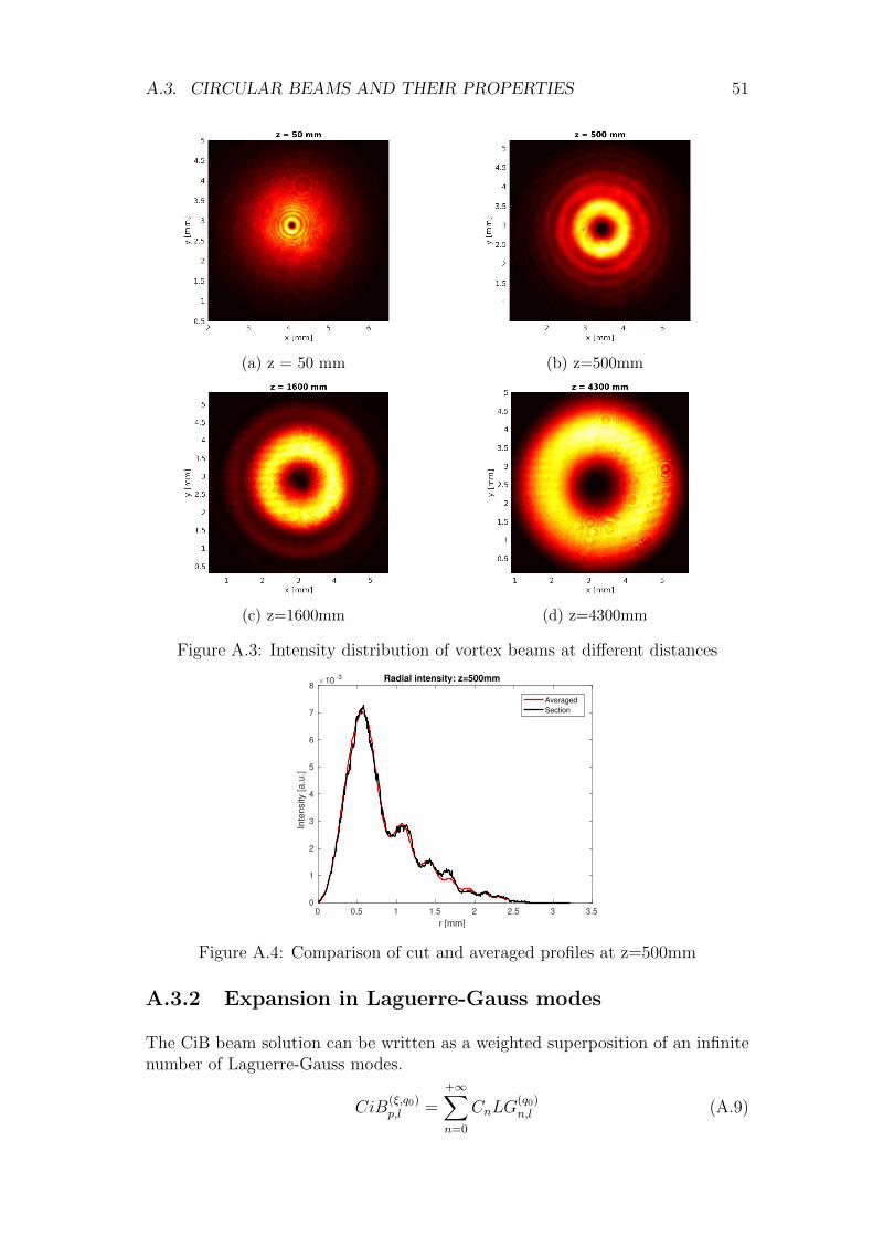
A.3. CIRCULAR BEAMS AND THEIR PROPERTIES 51
(a) z = 50 mm (b) z=500mm
(c) z=1600mm (d) z=4300mm
Figure A.3: Intensity distribution of vortex beams at different distances
0 0.5 1 1.5 2 2.5 3 3.5
r [mm]
0
1
2
3
4
5
6
7
8
Inte
nsity [
a.u
.]
10 -3 Radial intensity: z=500mm
Averaged
Section
Figure A.4: Comparison of cut and averaged profiles at z=500mm
A.3.2 Expansion in Laguerre-Gauss modes
The CiB beam solution can be written as a weighted superposition of an infinitenumber of Laguerre-Gauss modes.
CiB(ξ,q0)p,l =
+∞∑n=0
CnLG(q0)n,l (A.9)
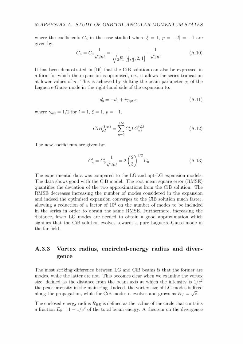
52APPENDIX A. STUDY OF ORBITAL ANGULAR MOMENTUM STATES
where the coefficients Cn in the case studied where ξ = 1, p = −|l| = −1 aregiven by:
Cn = C01√2n!
=1√
2F1
[12, 1
2, 2, 1
] · 1√2n!
(A.10)
It has been demostrated in [16] that the CiB solution can also be expressed ina form for which the expansion is optimised, i.e., it allows the series truncationat lower values of n. This is achieved by shifting the beam parameter q0 of theLaguerre-Gauss mode in the right-hand side of the expansion to:
q′0 = −d0 + iγoptz0 (A.11)
where γopt = 1/2 for l = 1, ξ = 1, p = −1.
CiB(ξ,q0)p,l =
+∞∑n=0
C ′nLG(q′0)n,l (A.12)
The new coefficients are given by:
C ′n = C ′01√2n!
= 2
(2
3
)3/2
C0 (A.13)
The experimental data was compared to the LG and opt-LG expansion models.The data shows good with the CiB model. The root-mean-square-error (RMSE)quantifies the deviation of the two approximations from the CiB solution. TheRMSE decreases increasing the number of modes considered in the expansionand indeed the optimised expansion converges to the CiB solution much faster,allowing a reduction of a factor of 102 on the number of modes to be includedin the series in order to obrain the same RMSE. Furthermore, increasing thedistance, fewer LG modes are needed to obtain a good approximation whichsignifies that the CiB solution evolves towards a pure Laguerre-Gauss mode inthe far field.
A.3.3 Vortex radius, encircled-energy radius and diver-gence
The most striking difference between LG and CiB beams is that the former aremodes, while the latter are not. This becomes clear when we examine the vortexsize, defined as the distance from the beam axis at which the intensity is 1/e2
the peak intensity in the main ring. Indeed, the vortex size of LG modes is fixedalong the propagation, while for CiB modes it evolves and grows as RV ∝
√z.
The enclosed-energy radius REE is defined as the radius of the circle that containsa fraction E0 = 1− 1/e2 of the total beam energy. A theorem on the divergence
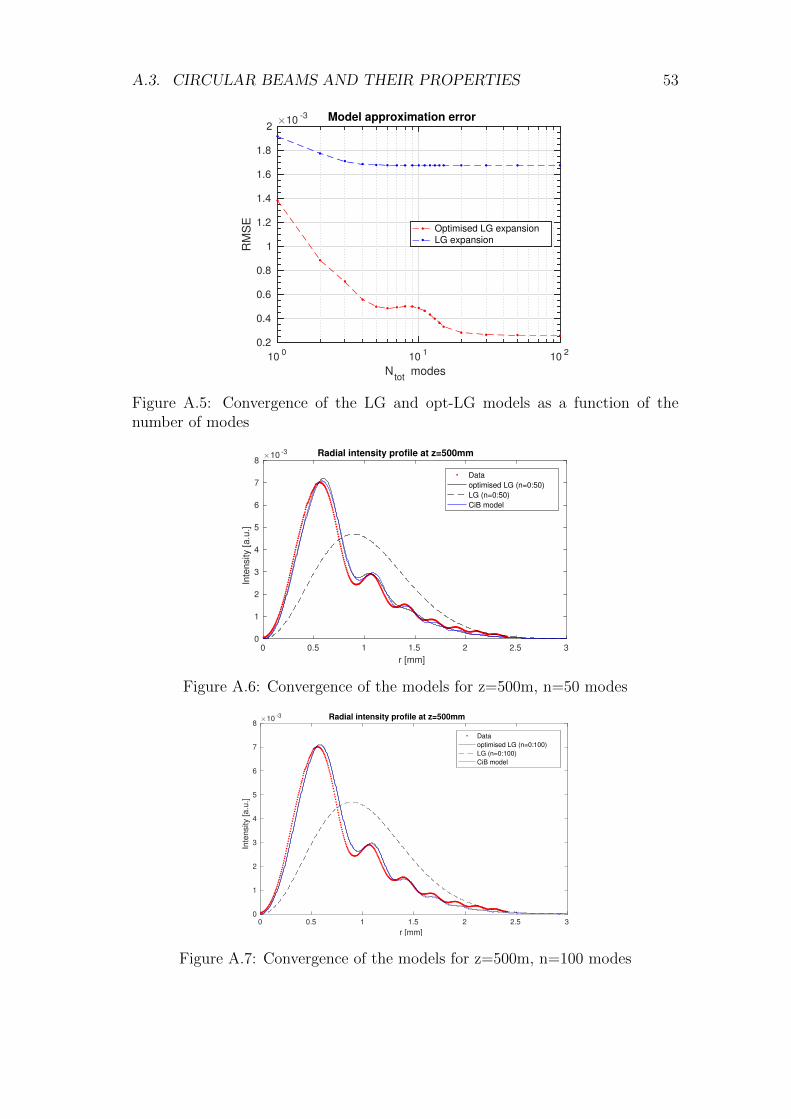
A.3. CIRCULAR BEAMS AND THEIR PROPERTIES 53
100
101
102
Ntot
modes
0.2
0.4
0.6
0.8
1
1.2
1.4
1.6
1.8
2
RM
SE
10-3 Model approximation error
Optimised LG expansion
LG expansion
Figure A.5: Convergence of the LG and opt-LG models as a function of thenumber of modes
0 0.5 1 1.5 2 2.5 3
r [mm]
0
1
2
3
4
5
6
7
8
Inte
nsity [a.u
.]
10 -3 Radial intensity profile at z=500mm
Data
optimised LG (n=0:50)
LG (n=0:50)
CiB model
Figure A.6: Convergence of the models for z=500m, n=50 modes
0 0.5 1 1.5 2 2.5 3
r [mm]
0
1
2
3
4
5
6
7
8
Inte
nsity [
a.u
.]
10 -3 Radial intensity profile at z=500mm
Data
optimised LG (n=0:100)
LG (n=0:100)
CiB model
Figure A.7: Convergence of the models for z=500m, n=100 modes
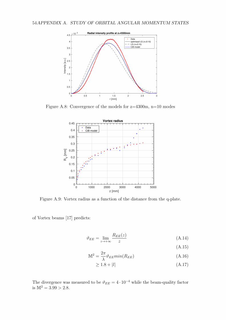
54APPENDIX A. STUDY OF ORBITAL ANGULAR MOMENTUM STATES
0 0.5 1 1.5 2 2.5 3
r [mm]
0
0.5
1
1.5
2
2.5
3
3.5
4
4.5
Inte
nsity [a.u
.]
10 -3 Radial intensity profile at z=4300mm
Data
optimised LG (n=0:10)
LG (n=0:10)
CiB model
Figure A.8: Convergence of the models for z=4300m, n=10 modes
0 1000 2000 3000 4000 5000
z [mm]
0
0.05
0.1
0.15
0.2
0.25
0.3
0.35
0.4
0.45
RV
[m
m]
Vortex radius
Data
CiB model
Figure A.9: Vortex radius as a function of the distance from the q-plate.
of Vortex beams [17] predicts:
ϑEE = limz→+∞
REE(z)
z(A.14)
(A.15)
M2 =2π
λϑEEmin(REE) (A.16)
≥ 1.8 + |l| (A.17)
The divergence was measured to be ϑEE = 4 · 10−4 while the beam-quality factoris M2 = 3.99 > 2.8.
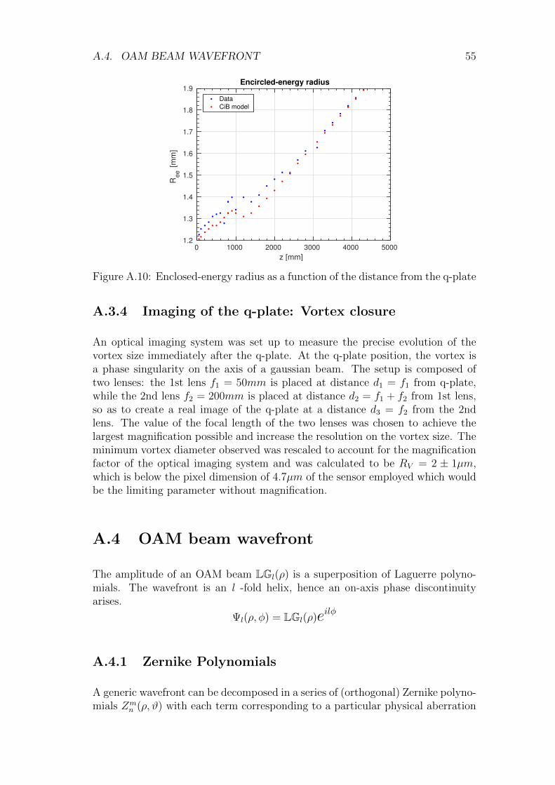
A.4. OAM BEAM WAVEFRONT 55
0 1000 2000 3000 4000 5000
z [mm]
1.2
1.3
1.4
1.5
1.6
1.7
1.8
1.9
Ree
[m
m]
Encircled-energy radius
Data
CiB model
Figure A.10: Enclosed-energy radius as a function of the distance from the q-plate
A.3.4 Imaging of the q-plate: Vortex closure
An optical imaging system was set up to measure the precise evolution of thevortex size immediately after the q-plate. At the q-plate position, the vortex isa phase singularity on the axis of a gaussian beam. The setup is composed oftwo lenses: the 1st lens f1 = 50mm is placed at distance d1 = f1 from q-plate,while the 2nd lens f2 = 200mm is placed at distance d2 = f1 + f2 from 1st lens,so as to create a real image of the q-plate at a distance d3 = f2 from the 2ndlens. The value of the focal length of the two lenses was chosen to achieve thelargest magnification possible and increase the resolution on the vortex size. Theminimum vortex diameter observed was rescaled to account for the magnificationfactor of the optical imaging system and was calculated to be RV = 2 ± 1µm,which is below the pixel dimension of 4.7µm of the sensor employed which wouldbe the limiting parameter without magnification.
A.4 OAM beam wavefront
The amplitude of an OAM beam LGl(ρ) is a superposition of Laguerre polyno-mials. The wavefront is an l -fold helix, hence an on-axis phase discontinuityarises.
Ψl(ρ, φ) = LGl(ρ)eilφ
A.4.1 Zernike Polynomials
A generic wavefront can be decomposed in a series of (orthogonal) Zernike polyno-mials Zm
n (ρ, ϑ) with each term corresponding to a particular physical aberration
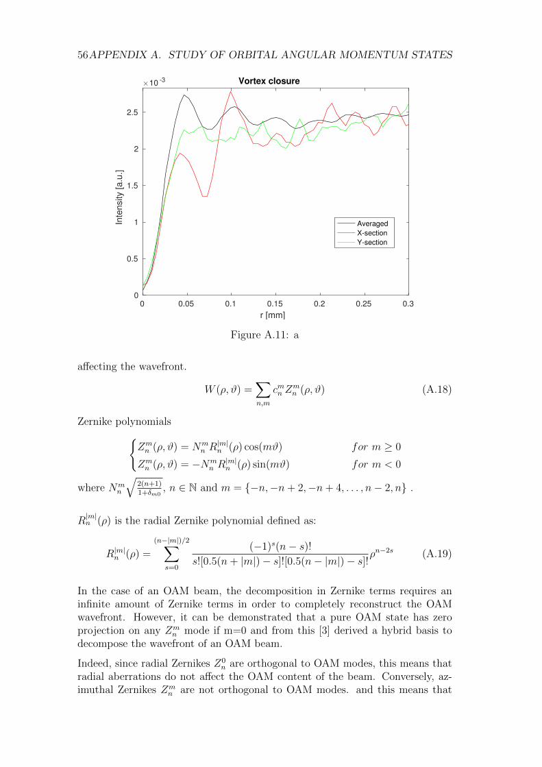
56APPENDIX A. STUDY OF ORBITAL ANGULAR MOMENTUM STATES
0 0.05 0.1 0.15 0.2 0.25 0.3
r [mm]
0
0.5
1
1.5
2
2.5In
tensity [
a.u
.]
10 -3 Vortex closure
Averaged
X-section
Y-section
Figure A.11: a
affecting the wavefront.
W (ρ, ϑ) =∑n,m
cmn Zmn (ρ, ϑ) (A.18)
Zernike polynomialsZmn (ρ, ϑ) = Nm
n R|m|n (ρ) cos(mϑ) for m ≥ 0
Zmn (ρ, ϑ) = −Nm
n R|m|n (ρ) sin(mϑ) for m < 0
where Nmn
√2(n+1)1+δm0
, n ∈ N and m = −n,−n+ 2,−n+ 4, . . . , n− 2, n .
R|m|n (ρ) is the radial Zernike polynomial defined as:
R|m|n (ρ) =
(n−|m|)/2∑s=0
(−1)s(n− s)!s![0.5(n+ |m|)− s]![0.5(n− |m|)− s]!
ρn−2s (A.19)
In the case of an OAM beam, the decomposition in Zernike terms requires aninfinite amount of Zernike terms in order to completely reconstruct the OAMwavefront. However, it can be demonstrated that a pure OAM state has zeroprojection on any Zm
n mode if m=0 and from this [3] derived a hybrid basis todecompose the wavefront of an OAM beam.
Indeed, since radial Zernikes Z0n are orthogonal to OAM modes, this means that
radial aberrations do not affect the OAM content of the beam. Conversely, az-imuthal Zernikes Zm
n are not orthogonal to OAM modes. and this means that
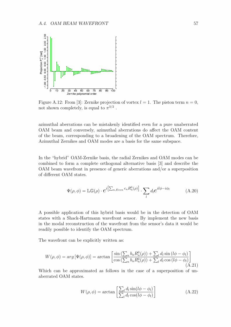
A.4. OAM BEAM WAVEFRONT 57
Figure A.12: From [3]: Zernike projection of vortex l = 1. The piston term n = 0,not shown completely, is equal to π3/2 .
azimuthal aberrations can be mistakenly identified even for a pure unaberratedOAM beam and conversely, azimuthal aberrations do affect the OAM contentof the beam, corresponding to a broadening of the OAM spectrum. Therefore,Azimuthal Zernikes and OAM modes are a basis for the same subspace.
In the “hybrid” OAM-Zernike basis, the radial Zernikes and OAM modes can becombined to form a complete orthogonal alternative basis [3] and describe theOAM beam wavefront in presence of generic aberrations and/or a superpositionof different OAM states.
Ψ(ρ, φ) = LG(ρ) · ei[∑
n,Even cnR0n(ρ)] ·
∑l
dleilφ−iφl (A.20)
A possible application of this hybrid basis would be in the detection of OAMstates with a Shack-Hartmann wavefront sensor. By implement the new basisin the modal reconstruction of the wavefront from the sensor’s data it would bereadily possible to identify the OAM spectrum.
The wavefront can be explicitly written as:
W (ρ, φ) = arg [Ψ(ρ, φ)] = arctan
[sin (
∑n bnR
0n(ρ)) +
∑l dl sin (lφ− φl)
cos (∑
n bnR0n(ρ)) +
∑l dl cos (lφ− φl)
](A.21)
Which can be approximated as follows in the case of a superposition of un-aberrated OAM states.
W (ρ, φ) = arctan
[∑l dl sin(lφ− φl)∑l dl cos(lφ− φl)
](A.22)
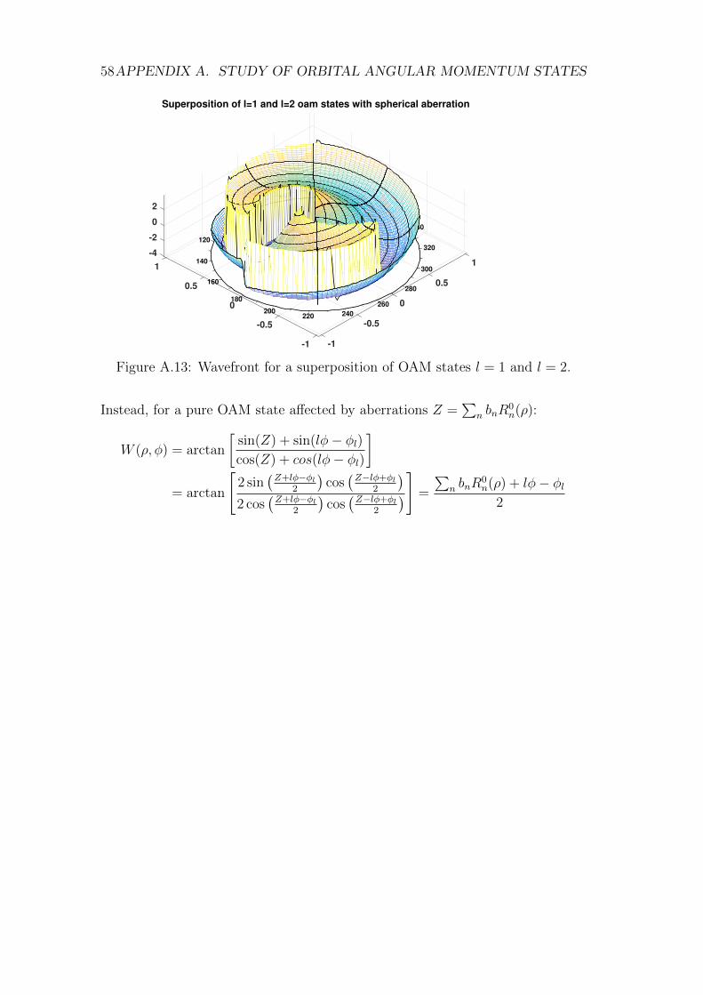
58APPENDIX A. STUDY OF ORBITAL ANGULAR MOMENTUM STATES
4060 2080
0
100340
120320
300
240
-411
140
0.50.5160
280
01800 260
-2
200220
-0.5-0.5
-1-1
0
Superposition of l=1 and l=2 oam states with spherical aberration
2
Figure A.13: Wavefront for a superposition of OAM states l = 1 and l = 2.
Instead, for a pure OAM state affected by aberrations Z =∑
n bnR0n(ρ):
W (ρ, φ) = arctan
[sin(Z) + sin(lφ− φl)cos(Z) + cos(lφ− φl)
]= arctan
[2 sin
(Z+lφ−φl
2
)cos(Z−lφ+φl
2
)2 cos
(Z+lφ−φl
2
)cos(Z−lφ+φl
2
)] =
∑n bnR
0n(ρ) + lφ− φl
2
Bibliography
[1] M. Fleischhauer and M. D. Lukin, “Dark-State Polaritons in Electromagnet-ically Induced Transparency,” Phys. Rev.Lett., vol. 84, no. 22, 2000.
[2] M. Namazi, G. Vallone, B. Jordaan, C. Goham, R. Shahrokhshahi, P. Vil-loresi, and E. Figueroa, “Free space quantum communication with quantummemory,” preprint available at arXiv:1609.08676, 2016.
[3] N. Uribe-Patarroyo, A. Alvarez-Herrero, and T. Belenguer, “A comprehen-sive approach to deal with instrumental optical aberrations effects in high-accuracy photon’s orbital angular momentum spectrum measurements,” Op-tics Express, vol. 18, no. 20, p. 21111, 2010.
[4] I. Damgard, S. Fehr, L. Salvail, and C. Schaffner, “Secure identificationand QKD in the bounded-quantum-storage model,” Theoretical ComputerScience, vol. 560, no. P1, pp. 12–26, 2014.
[5] A. K. Ekert, “Quantum Cryptography Based on Bell’s Theorem,” Phys.Rev.Lett., vol. 67, no. 6, pp. 661–663, 1991.
[6] H.-k. Lo, M. Curty, and B. Qi, “Measurement-Device-Independent QuantumKey Distribution,” vol. 130503, no. March, pp. 1–5, 2012.
[7] S. Harris, “Eletromagnetically Induced Transparency,” Physics Today,pp. 36–42, 1997.
[8] G. Brennen, E. Giacobino, and C. Simon, “Focus on Quantum Memory,”New Journal of Physics, vol. 17, 2015.
[9] C. Simon, M. Afzelius, Appel, et al., “Quantum memories :A review basedon the European integrated project”Qubit Applications (QAP)”,” EuropeanPhysical Journal D, vol. 58, no. 1, pp. 1–22, 2010.
[10] M. Namazi, C. Kupchak, B. Jordaan, R. Shahrokhshahi, and E. Figueroa,“Unconditional polarization qubit quantum memory at room temperature,”pp. 1–6, 2015.
59
60 BIBLIOGRAPHY
[11] C. K. Hong, Z. Y. Ou, and L. Mandel, “Measurement of Subpicosecond TimeIntervals Between Two Photo By Interference,” Phys. Rev.Lett., vol. 59,no. 18, pp. 2044–2046, 1987.
[12] J. Jin, J. A. Slater, E. Saglamyurek, N. Sinclair, M. George, R. Ricken,D. Oblak, W. Sohler, and W. Tittel, “Two-photon interference of weak co-herent laser pulses recalled from separate solid-state quantum memories,”Nature Communications, vol. 4, pp. 1–7, 2013.
[13] Balogh Laszlo, “Design And Application Guide For High Speed MOSFETGate Drive Circuits,” tech. rep., 1998.
[14] G. Vallone, V. D’Ambrosio, A. Sponselli, S. Slussarenko, L. Marrucci,F. Sciarrino, and P. Villoresi, “Free-space quantum key distribution byrotation-invariant twisted photons,” Physical Review Letters, vol. 113, no. 6,pp. 1–8, 2014.
[15] L. Marrucci, E. Karimi, S. Slussarenko, B. Piccirillo, E. Santamato, E. Na-gali, and F. Sciarrino, “Spin-to-orbital conversion of the angular momen-tum of light and its classical and quantum applications,” Journal of Optics,vol. 13, no. 6, p. 064001, 2011.
[16] G. Vallone, “Role of beam waist in Laguerre – Gauss expansion of vortexbeams,” Optics Letters, vol. 42, no. 6, pp. 1097–1100, 2017.
[17] G. Vallone, “On the properties of circular beams: normalization, La-guerre–Gauss expansion, and free-space divergence,” Optics Letters, vol. 40,no. 8, p. 1717, 2015.
[18] N. Brunner, N. Gisin, S. Massar, S. Pironio, and V. Scarani, “Device-Independent Security of Quantum Cryptography against Collective At-tacks,” Phys. Rev.Lett., vol. 98, no. June, pp. 1–4, 2007.
[19] N. L. Piparo, N. Sinclair, and M. Razavi, “Memory-assisted quantum keydistribution resilient against multiple-excitation effects,” vol. 1, 2017.
[20] N. Gisin and R. Thew, “Quantum Communication,” Nature Photonics,vol. 1, 2007.
[21] N. Gisin, G. Ribordy, W. Tittel, and H. Zbinden, “Quantum cryptography,”Reviews of Modern Physics, vol. 74, no. 1, pp. 145–195, 2002.
[22] R. Ursin, F. Tiefenbacher, T. Schmitt-Manderbach, H. Weier, T. Scheidl,M. Lindenthal, B. Blauensteiner, T. Jennewein, J. Perdigues, P. Trojek,B. Omer, M. Furst, M. Meyenburg, J. Rarity, Z. Sodnik, C. Barbieri, H. We-infurter, and A. Zeilinger, “Entanglement-based quantum communicationover 144km,” Nature Physics, vol. 3, no. 7, pp. 481–486, 2007.
[23] Z. Tang, Z. Liao, F. Xu, B. Qi, L. Qian, and H.-K. Lo, “Experimental Demon-stration of Polarization Encoding Measurement-Device-Independent Quan-tum Key Distribution,” Physical Review Letters, vol. 112, no. 19, p. 190503,2014.
BIBLIOGRAPHY 61
[24] I. Novikova, R. Walsworth, and Y. Xiao, “EIT-based slow and stored lightin warm atoms,” Laser & Photonics Reviews, no. July, pp. 1–21, 2011.
[25] M. Fleischhauer and J. Marangos, “Electromagnetically induced trans-parency : Optics in coherent media,” Reviews of Modern Physics, vol. 77,no. April, pp. 633–673, 2005.
[26] C. Kupchak, T. Mittiga, B. Jordaan, M. Namazi, C. Nolleke, andE. Figueroa, “Room-Temperature Single-photon level Memory for Polariza-tion States,” Scientific Reports, vol. 5, p. 7658, 2015.
[27] M. Namazi, T. Mittiga, C. Kupchak, and E. Figueroa, “Cascading QuantumLight-Matter Interfaces,” Phys. Rev. A, vol. 92, 2015.
[28] K. Boller, A. Imamolu, and S. Harris, “Observation of electromagneticallyinduced transparency,” Physical Review Letters, vol. 66, no. 20, pp. 2593–2596, 1991.
[29] W. W. Erickson, Electromagnetically Induced Transparency. PhD thesis,2012.
[30] H. Chen, X.-B. An, J. Wu, Z.-Q. Yin, S. Wang, W. Chen, and Z.-F. Han,“Hong–Ou–Mandel interference with two independent weak coherent states,”Chinese Physics B, vol. 25, no. 2, p. 020305, 2016.
[31] P. Marek, P. Zapletal, R. Filip, Y. Hashimoto, T. Toyama, J.-i. Yoshikawa,K. Makino, and A. Furusawa, “Direct observation of phase sensitive Hong-Ou-Mandel interference,” 2017.
[32] T. Wilk, Quantum Interface between an Atom and a Photon. PhD thesis,2008.
[33] Y. S. Kim, O. Slattery, P. S. Kuo, and X. Tang, “Conditions for two-photoninterference with coherent pulses,” Physical Review A - Atomic, Molecular,and Optical Physics, vol. 87, no. 6, pp. 1–5, 2013.
[34] G. Vallone, G. Parisi, F. Spinello, E. Mari, F. Tamburini, and P. Villoresi,“General theorem on the divergence of vortex beams,” Physical Review A,vol. 94, no. 2, pp. 1–8, 2016.
[35] B. Piccirillo, V. D’Ambrosio, S. Slussarenko, L. Marrucci, and E. Santamato,“Photon spin-to-orbital angular momentum conversion via an electricallytunable q -plate,” Applied Physics Letters, vol. 97, no. 24, pp. 4085–4090,2010.
[36] B. Piccirillo, V. Kumar, L. Marrucci, and E. Santamato, “Pancharatnam-Berry phase optical elements for generation and control of complex light:generalized superelliptical q-plates,” Spie Opto, vol. 9379, p. 937907, 2015.
[37] N. Uribe-Patarroyo, A. Alvarez-Herrero, and T. Belenguer, “Measurementof the quantum superposition state of an imaging ensemble of photons pre-pared in orbital angular momentum states using a phase-diversity method,”Physical Review A - Atomic, Molecular, and Optical Physics, vol. 81, 2010.
62 BIBLIOGRAPHY
[38] F. a. Starikov, G. G. Kochemasov, S. M. Kulikov, a. N. Manachinsky, N. V.Maslov, a. V. Ogorodnikov, S. a. Sukharev, V. P. Aksenov, I. V. Izmailov,F. Y. Kanev, V. V. Atuchin, and I. S. Soldatenkov, “Wavefront recon-struction of an optical vortex by a Hartmann-Shack sensor.,” Optics letters,vol. 32, no. 16, pp. 2291–3, 2007.
[39] L. Seifert, H. J. Tiziani, and W. Osten, “Wavefront reconstruction with theadaptive Shack-Hartmann sensor,” Optics Communications, vol. 245, no. 1-6, pp. 255–269, 2005.
[40] M. Nielsen and I. Chuang, Quantum Computation and Quantum Informa-tion. Cambridge UP, 2010.
[41] U. Leohnhardt, Measuring the Quantum State of Light. Cambridge UP, 1997.
[42] V. Vedral, Introduction to Quantum Information Science. Oxford UP, 2006.
[43] B. Saleh and M. Teich, Fundamentals of Photonics. Wiley, 2007.
Related Documents