SECTION 6.5 Quantum Mechanics and Atomic Orbitals 219 GIVE IT SOME THOUGHT What is the principal reason we must consider the uncertainty principle when discussing electrons and other subatomic particles but not when discussing our macroscopic world? 6.5 | QUANTUM MECHANICS AND ATOMIC ORBITALS In 1926 the Austrian physicist Erwin Schrödinger (1887–1961) proposed an equation, now known as Schrödinger’s wave equation, that incorporates both the wave-like behav- ior of the electron and its particle-like behavior. His work opened a new approach to dealing with subatomic particles, an approach known as quantum mechanics or wave mechanics. The application of Schrödinger’s equation requires advanced calculus, and so we will not be concerned with its details. We will, however, qualitatively consider the results Schrödinger obtained because they give us a powerful new way to view electronic structure. Let’s begin by examining the electronic structure of the simplest atom, hydrogen. Schrödinger treated the electron in a hydrogen atom like the wave on a plucked gui- tar string ( FIGURE 6.15). Because such waves do not travel in space, they are called standing waves. Just as the plucked guitar string produces a standing wave that has a fun- damental frequency and higher overtones (harmonics), the electron exhibits a lowest-energy standing wave and higher-energy ones. Furthermore, just as the over- tones of the guitar string have nodes, points where the amplitude of the wave is zero, so do the waves characteristic of the electron. Solving Schrödinger’s equation for the hydrogen atom leads to a series of mathemat- ical functions called wave functions that describe the electron in an atom. These wave functions are usually represented by the symbol (lowercase Greek letter psi). Although the wave function has no direct physical meaning, the square of the wave function, , provides information about the electron’s location when it is in an allowed energy state. For the hydrogen atom, the allowed energies are the same as those predicted by the Bohr model. However, the Bohr model assumes that the electron is in a circular orbit of some particular radius about the nucleus. In the quantum mechanical model, the elec- tron’s location cannot be described so simply. According to the uncertainty principle, if we know the momentum of the electron with high accuracy, our simultaneous knowledge of its location is very uncertain. Thus, we cannot hope to specify the exact location of an individual electron around the c 2 c Fundamental First overtone Second overtone 1 node n = 1 n = 2 n = 3 2 nodes FIGURE 6.15 Standing waves in a vibrating string.

Welcome message from author
This document is posted to help you gain knowledge. Please leave a comment to let me know what you think about it! Share it to your friends and learn new things together.
Transcript

SECTION 6.5 Quantum Mechanics and Atomic Orbitals 219
G I V E I T S O M E T H O U G H T
What is the principal reason we must consider the uncertainty principle whendiscussing electrons and other subatomic particles but not when discussing ourmacroscopic world?
6.5 | QUANTUM MECHANICS AND ATOMIC ORBITALS
In 1926 the Austrian physicist Erwin Schrödinger (1887–1961) proposed an equation,now known as Schrödinger’s wave equation, that incorporates both the wave-like behav-ior of the electron and its particle-like behavior. His work opened a new approach todealing with subatomic particles, an approach known as quantum mechanics or wavemechanics. The application of Schrödinger’s equation requires advanced calculus, and so wewill not be concerned with its details. We will, however, qualitatively consider the resultsSchrödinger obtained because they give us a powerful new way to view electronic structure.Let’s begin by examining the electronic structure of the simplest atom, hydrogen.
Schrödinger treated the electron in a hydrogen atom like the wave on a plucked gui-tar string (� FIGURE 6.15). Because such waves do not travel in space, they are calledstanding waves. Just as the plucked guitar string produces a standing wave that has a fun-damental frequency and higher overtones (harmonics), the electron exhibits alowest-energy standing wave and higher-energy ones. Furthermore, just as the over-tones of the guitar string have nodes, points where the amplitude of the wave is zero, sodo the waves characteristic of the electron.
Solving Schrödinger’s equation for the hydrogen atom leads to a series of mathemat-ical functions called wave functions that describe the electron in an atom. These wavefunctions are usually represented by the symbol (lowercase Greek letter psi). Althoughthe wave function has no direct physical meaning, the square of the wave function, ,provides information about the electron’s location when it is in an allowed energy state.
For the hydrogen atom, the allowed energies are the same as those predicted by theBohr model. However, the Bohr model assumes that the electron is in a circular orbit ofsome particular radius about the nucleus. In the quantum mechanical model, the elec-tron’s location cannot be described so simply.
According to the uncertainty principle, if we know the momentum of the electronwith high accuracy, our simultaneous knowledge of its location is very uncertain. Thus,we cannot hope to specify the exact location of an individual electron around the
c2c
Fundamental
First overtone
Second overtone
1 node
n = 1
n = 2
n = 3
2 nodes
� FIGURE 6.15 Standing waves in avibrating string.

y
x
High dot density, high c2
value, high probablility of finding electron in this region
Low dot density, low c2
value, low probability of finding electron in this region
z
� FIGURE 6.16 Electron-densitydistribution. This rendering represents theprobability, , of finding the electron in ahydrogen atom in its ground state. The originof the coordinate system is at the nucleus.
c2
220 CHAPTER 6 Electronic Structure of Atoms
nucleus. Rather, we must be content with a kind of statistical knowledge. We thereforespeak of the probability that the electron will be in a certain region of space at a given in-stant. As it turns out, the square of the wave function, , at a given point in spacerepresents the probability that the electron will be found at that location. For this rea-son, is called either the probability density or the electron density.
One way of representing the probability of finding the electron in various regionsof an atom is shown in � FIGURE 6.16, where the density of the dots represents theprobability of finding the electron. The regions with a high density of dots correspondto relatively large values for and are therefore regions where there is a high probabil-ity of finding the electron. Based on this representation, we often describe atoms asconsisting of a nucleus surrounded by an electron cloud.
Orbitals and Quantum NumbersThe solution to Schrödinger’s equation for the hydrogen atom yields a set of wave func-tions called orbitals. Each orbital has a characteristic shape and energy. For example, thelowest-energy orbital in the hydrogen atom has the spherical shape illustrated in Figure6.16 and an energy of . Note that an orbital (quantum mechanicalmodel, which describes electrons in terms of probabilities, visualized as “electronclouds”) is not the same as an orbit (Bohr model, which visualizes the electron movingin a physical orbit, like a planet around a star). The quantum mechanical model doesnot refer to orbits because the motion of the electron in an atom cannot be preciselydetermined (Heisenberg uncertainty principle).
The Bohr model introduced a single quantum number, n, to describe an orbit. Thequantum mechanical model uses three quantum numbers, n, l, and , which resultnaturally from the mathematics used, to describe an orbital.
1. The principal quantum number, n, can have positive integral values 1, 2, 3, . . . . Asn increases, the orbital becomes larger, and the electron spends more time fartherfrom the nucleus. An increase in n also means that the electron has a higher en-ergy and is therefore less tightly bound to the nucleus. For the hydrogen atom,
, as in the Bohr model.
2. The second quantum number—the angular momentum quantum number, l—canhave integral values from 0 to for each value of n. This quantum numberdefines the shape of the orbital. The value of l for a particular orbital is generallydesignated by the letters s, p, d, and f, * corresponding to l values of 0, 1, 2, and 3:
3. The magnetic quantum number, , can have integral values between and l, in-cluding zero. This quantum number describes the orientation of the orbital inspace, as we discuss in Section 6.6.
Notice that because the value of n can be any positive integer, an infinite number oforbitals for the hydrogen atom are possible. At any given instant, however, the electronin a hydrogen atom is described by only one of these orbitals—we say that the electronoccupies a certain orbital. The remaining orbitals are unoccupied for that particular stateof the hydrogen atom.
G I V E I T S O M E T H O U G H T
What is the difference between an orbit in the Bohr model of the hydrogen atomand an orbital in the quantum mechanical model?
The collection of orbitals with the same value of n is called an electron shell. Allthe orbitals that have , for example, are said to be in the third shell. The set ofn = 3
- lml
0
s
1
p
2
d
3
f
Value of l
Letter used
(n - 1)
En = -(2.18 * 10-18 J)(1>n2)
ml
-2.18 * 10-18 J
c2
c2
c2
*The letters come from the words sharp, principal, diffuse, and fundamental, which were used to describecertain features of spectra before quantum mechanics was developed.
G O F I G U R E
Where in the figure is the region ofhighest electron density?
SECTION 6.5 Quantum Mechanics and Atomic Orbitals 221
orbitals that have the same n and l values is called a subshell. Each subshell is designatedby a number (the value of n) and a letter (s, p, d, or f, corresponding to the value of l ).For example, the orbitals that have and are called 3d orbitals and are in the3d subshell.
� TABLE 6.2 summarizes the possible values of l and for values of n through. The restrictions on possible values give rise to the following very important
observations:
1. The shell with principal quantum number n consists of exactly n subshells. Eachsubshell corresponds to a different allowed value of l from 0 to . Thus, thefirst shell consists of only one subshell, the ; the second shell
consists of two subshells, the and ; thethird shell consists of three subshells, 3s, 3p, and 3d, and so forth.
2. Each subshell consists of a specific number of orbitals. Each orbitalcorresponds to a different allowed value of . For a given value of l,there are allowed values of , ranging from to . Thus,each subshell consists of one orbital; each sub-shell consists of three orbitals; each subshell consists of fiveorbitals, and so forth.
3. The total number of orbitals in a shell is , where n is the principalquantum number of the shell. The resulting number of orbitals forthe shells—1, 4, 9, 16—are related to a pattern seen in the periodictable: We see that the number of elements in the rows of the periodictable—2, 8, 18, and 32—equals twice these numbers. We will discussthis relationship further in Section 6.9.
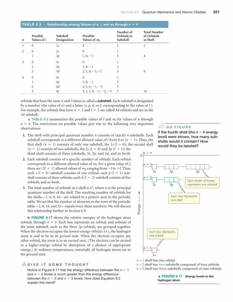
� FIGURE 6.17 shows the relative energies of the hydrogen atomorbitals through . Each box represents an orbital, and orbitals ofthe same subshell, such as the three 2p orbitals, are grouped together.When the electron occupies the lowest-energy orbital (1s ), the hydrogenatom is said to be in its ground state. When the electron occupies anyother orbital, the atom is in an excited state. (The electron can be excitedto a higher-energy orbital by absorption of a photon of appropriateenergy.) At ordinary temperatures, essentially all hydrogen atoms are inthe ground state.
G I V E I T S O M E T H O U G H T
Notice in Figure 6.17 that the energy difference between the and levels is much greater than the energy difference between the and levels. How does Equation 6.5 explain this trend?
n = 3n = 2n = 2
n = 1
n = 3
n2
d (l = 2)p (l = 1)s (l = 0)
+ l- lml(2l + 1)ml
2p (l = 1)2s (l = 0)(n = 2)1s (l = 0)(n = 1)
(n - 1)
n = 4ml
l = 2n = 3
TABLE 6.2 • Relationship among Values of n, l, and ml through n 4�
nPossible Values of l
Subshell Designation
Possible Values of ml
Number ofOrbitals in Subshell
Total Number of Orbitals in Shell
1 0 1s 0 1 1
2 0 2s 0 1
1 2p 1, 0, -1 3 4
3 0 3s 0 1
1 3p 1, 0, -1 3
2 3d 2, 1, 0, ,-2-1 5 9
4 0 4s 0 1
1 4p 1, 0, -1 3
2 4d 2, 1, 0, , -2-1 5
3 4f 3, 2, 1, 0, , , -3-2-1 7 16
Ene
rgy
n � �
n � 3
0
3s 3p
n � 2
2s
n � 1
1s
2p
3d
Each box representsone orbital
Each row representsone shell
Each cluster of boxesrepresents one subshell
n = 1 shell has one orbitaln = 2 shell has two subshells composed of four orbitalsn = 3 shell has three subshells composed of nine orbitals
� FIGURE 6.17 Energy levels in thehydrogen atom.
G O F I G U R E
If the fourth shell (the n = 4 energylevel) were shown, how many sub-shells would it contain? Howwould they be labeled?

222 CHAPTER 6 Electronic Structure of Atoms
SAMPLE EXERCISE 6.6 Subshells of the Hydrogen Atom
(a) Without referring to Table 6.2, predict the number of subshells in the fourth shell, that is,for . (b) Give the label for each of these subshells. (c) How many orbitals are in each ofthese subshells?
Analyze and Plan We are given the value of the principal quantum number, n. We need todetermine the allowed values of l and for this given value of n and then count the numberof orbitals in each subshell.
SOLUTIONThere are four subshells in the fourth shell, corresponding to the four possible values of l (0, 1,2, and 3).
These subshells are labeled 4s, 4p, 4d, and 4f. The number given in the designation of asubshell is the principal quantum number, n; the letter designates the value of the angular mo-mentum quantum number, l : for , s; for , p; for , d; for .
There is one 4s orbital (when , there is only one possible value of : 0). There arethree 4p orbitals (when , there are three possible values of : 1, 0, ). There are five 4dorbitals (when , there are five allowed values of ). There are seven 4forbitals (when , there are seven permitted values of ).
PRACTICE EXERCISE(a) What is the designation for the subshell with and ? (b) How many orbitals arein this subshell? (c) Indicate the values of for each of these orbitals.Answers: (a) ; (b) 3; (c) 1, 0,
6.6 | REPRESENTATIONS OF ORBITALSSo far we have emphasized orbital energies, but the wave function also provides infor-mation about an electron’s probable location in space. Let’s examine the ways in whichwe can picture orbitals because their shapes help us visualize how the electron density isdistributed around the nucleus.
The s OrbitalsWe have already seen one representation of the lowest-energy orbital of the hydrogenatom, the 1s (Figure 6.16). The first thing we notice about the electron density for the 1sorbital is that it is spherically symmetric—in other words, the electron density at a givendistance from the nucleus is the same regardless of the direction in which we proceedfrom the nucleus. All of the other s orbitals (2s, 3s, 4s, and so forth) are also sphericallysymmetric and centered on the nucleus.
Recall that the l quantum number for the s orbitals is 0; therefore, the quantumnumber must be 0. Thus, for each value of n, there is only one s orbital.
So how do s orbitals differ as the value of n changes? One way to address this ques-tion is to look at the radial probability function, also called the radial probabilitydensity, which is defined as the probability that we will find the electron at a specific dis-tance from the nucleus.
� FIGURE 6.18 shows the radial probability density for the 1s, 2s, and 3s orbitals ofhydrogen as a function of r, the distance from the nucleus. Three features of thesegraphs are noteworthy: the number of peaks, the number of points at which the proba-bility function goes to zero (called nodes), and how spread out the distribution is,which gives a sense of the size of the orbital.
For the 1s orbital, we see that the probability rises rapidly as we move away from thenucleus, maximizing at about . Thus, when the electron occupies the 1s orbital, it ismost likely to be found this distance from the nucleus.* Notice also that in the 1s orbitalthe probability of finding the electron at a distance greater than about from thenucleus is essentially zero.
3 Å
0.5 Å
ml
-15pml
l = 1n = 5
ml: 3, 2, 1, 0, -1, -2, -3l = 3ml: 2, 1, 0, -1, -2l = 2
-1mll = 1mll = 0
l = 3, fl = 2l = 1l = 0
ml
n = 4
*In the quantum mechanical model, the most probable distance at which to find the electron in the 1s orbitalis actually , the same as the radius of the orbit predicted by Bohr for . The distance isoften called the Bohr radius.
0.529 Ån = 10.529 Å

SECTION 6.6 Representations of Orbitals 223
Comparing the radial probability distributions for the 1s, 2s, and 3s orbitals revealsthree trends:
1. The number of peaks increases with increasing n, with the outermost peak beinglarger than inner ones.
2. The number of nodes increases with increasing n.
3. The electron density becomes more spread out with increasing n.
One widely used method of representing orbital shape is to draw a boundary sur-face that encloses some substantial portion, say , of the electron density for theorbital. This type of drawing is called a contour representation, and the contour repre-sentations for the s orbitals are spheres (� FIGURE 6.19). All the orbitals have the sameshape, but they differ in size, becoming larger as n increases, reflecting the fact that theelectron density becomes more spread out as n increases. Although the details of how
90%
0 1 2 3 4 5Distance from the nucleus, r (Å)
1s
Prob
abili
ty
6 7 8 9 10
1s
0 1
1 Node
2 Nodes
2 3 4 5Distance from the nucleus, r (Å)
2s
Prob
abili
ty
6 7 8 9 10
2s
0 1 2 3
3s
4 5Distance from the nucleus, r (Å)
3s
Prob
abili
ty
6 7 8 9 10
Most probable distance from nucleus ~ 0.5 Å
Most probable distance from nucleus ~ 3 Å
Most probable distance from nucleus ~ 7 Å
� FIGURE 6.18 Radial probability distributions for the 1s, 2s, and 3s orbitals ofhydrogen. These graphs of the radial probability function plot probability of finding the electronas a function of distance from the nucleus. As n increases, the most likely distance at which tofind the electron (the highest peak) moves farther from the nucleus.
G O F I G U R E
How many maxima would you expect to find in the radial probability functionfor the 4s orbital of the hydrogen atom? How many nodes would you expectin this function?
3s2s
1s
(a) (b)
� FIGURE 6.19 Comparison of the 1s,2s, and 3s orbitals. (a) Electron-densitydistribution of a 1s orbital. (b) Contourrepresentions of the 1s, 2s, and 3s orbitals.Each sphere is centered on the atom’snucleus and encloses the volume in whichthere is a 90% probability of finding theelectron.

224 CHAPTER 6 Electronic Structure of Atoms
electron density varies within a given contour representation are lost in these represen-tations, this is not a serious disadvantage. For qualitative discussions, the mostimportant features of orbitals are shape and relative size, which are adequately displayedby contour representations.
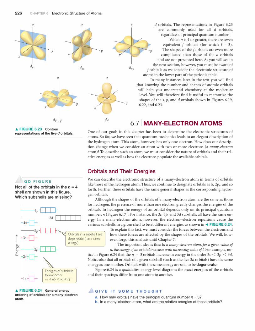
The p OrbitalsThe distribution of electron density for a 2p orbital is shown in � FIGURE 6.22(a). Theelectron density is not distributed spherically as in an s orbital. Instead, the density isconcentrated in two regions on either side of the nucleus, separated by a node at the nu-cleus. We say that this dumbbell-shaped orbital has two lobes. Recall that we are makingno statement of how the electron is moving within the orbital. Figure 6.22(a) portraysonly the averaged distribution of the electron density in a 2p orbital.
Beginning with the shell, each shell has three p orbitals. Recall that the lquantum number for p orbitals is 1. Therefore, the magnetic quantum number canhave three possible values: , 0, and . Thus, there are three 2p orbitals, three 3porbitals, and so forth, corresponding to the three possible values of . Each set of porbitals has the dumbbell shapes shown in Figure 6.22(a) for the 2p orbitals. For eachvalue of n, the three p orbitals have the same size and shape but differ from one anotherin spatial orientation. We usually represent p orbitals by drawing the shape and orienta-tion of their wave functions, as shown in Figure 6.22(b). It is convenient to label these asthe , , and orbitals. The letter subscript indicates the Cartesian axis along whichthe orbital is oriented.* Like s orbitals, p orbitals increase in size as we move from 2p to3p to 4p, and so forth.
pzpypx
ml
+1-1ml
n = 2
*We cannot make a simple correspondence between the subscripts (x, y, and z) and the allowed values (1, 0,and ). To explain why this is so is beyond the scope of an introductory text.-1
ml
Let’s examine the difference between probability density and ra-dial probability function more closely. � FIGURE 6.21 shows plotsof as a function of r for the 1s, 2s, and 3s orbitals of the[c(r)]2
PROBABILITY DENSITY AND RADIALPROBABILITY FUNCTIONS
According to quantum mechanics, we must describethe position of the electron in the hydrogen atom
in terms of probabilities. The information aboutthe probability is contained in the wave func-
tions, , obtained from Schrödinger’s equation. The square of thewave function, , called either the probability density or the elec-tron density, as noted earlier, gives the probability that the electronis at any point in space. Because s orbitals are spherically symmetric,the value of for an s electron depends only on its distance fromthe nucleus, r. Thus, the probability density can be written as
, where is the value of at r. This function givesthe probability density for any point located a distance r from thenucleus.
The radial probability function, which we used in Figure 6.18,differs from the probability density. The radial probability functionequals the total probability of finding the electron at all the points atany distance r from the nucleus. In other words, to calculate thisfunction, we need to “add up” the probability densities overall points located a distance r from the nucleus. � FIGURE 6.20compares the probability density at a point ( ) with the radialprobability function.
[c(r)]2
[c(r)]2
[c(r)]2cc(r)[c(r)]2
c
c2c
A CLOSER LOOK
� FIGURE 6.20 Comparing probability density and radial probability function .4Pr 2 [C (r )]2[C(r )]2
[y (r)]2 is probability density at any given point
4p r2[y (r)]2 is radial probabilityfunction � sum of all [y (r)]2
having any given value of r
SECTION 6.6 Representations of Orbitals 225
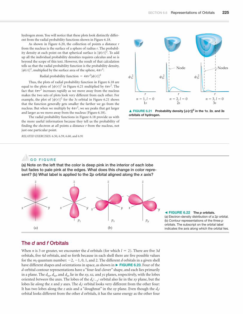
hydrogen atom. You will notice that these plots look distinctly differ-ent from the radial probability functions shown in Figure 6.18.
As shown in Figure 6.20, the collection of points a distance rfrom the nucleus is the surface of a sphere of radius r. The probabil-ity density at each point on that spherical surface is . To addup all the individual probability densities requires calculus and so isbeyond the scope of this text. However, the result of that calculationtells us that the radial probability function is the probability density,
, multiplied by the surface area of the sphere, :
Thus, the plots of radial probability function in Figure 6.18 areequal to the plots of in Figure 6.21 multiplied by . Thefact that increases rapidly as we move away from the nucleusmakes the two sets of plots look very different from each other. Forexample, the plot of for the 3s orbital in Figure 6.21 showsthat the function generally gets smaller the farther we go from thenucleus. But when we multiply by , we see peaks that get largerand larger as we move away from the nucleus (Figure 6.18).
The radial probability functions in Figure 6.18 provide us withthe more useful information because they tell us the probability offinding the electron at all points a distance r from the nucleus, notjust one particular point.
RELATED EXERCISES: 6.50, 6.59, 6.60, and 6.91
4pr2
[c(r)]2
4pr24pr2[c(r)]2
Radial probability function = 4pr2[c(r)]2
4pr2[c(r)]2
[c(r)]2
n � 1, l � 01s
rn � 2, l � 0
2s
Node Nodes
rn � 3, l � 0
3s
r
c2s2c1s
22 c3s
� FIGURE 6.21 Probability density in the 1s, 2s, and 3sorbitals of hydrogen.
[C(r )]2
px pypz
(a) (b)
x x x xy yyy
z z z z
� FIGURE 6.22 The p orbitals.(a) Electron-density distribution of a 2p orbital.(b) Contour representations of the three porbitals. The subscript on the orbital labelindicates the axis along which the orbital lies.
G O F I G U R E
(a) Note on the left that the color is deep pink in the interior of each lobebut fades to pale pink at the edges. What does this change in color repre-sent? (b) What label is applied to the 2p orbital aligned along the x axis?
The d and f OrbitalsWhen n is 3 or greater, we encounter the d orbitals (for which ). There are five 3dorbitals, five 4d orbitals, and so forth because in each shell there are five possible valuesfor the quantum number: , , 0, 1, and 2. The different d orbitals in a given shellhave different shapes and orientations in space, as shown in � FIGURE 6.23. Four of thed-orbital contour representations have a “four-leaf clover” shape, and each lies primarilyin a plane. The , , and lie in the xy, xz, and yz planes, respectively, with the lobesoriented between the axes. The lobes of the orbital also lie in the xy plane, but thelobes lie along the x and y axes. The orbital looks very different from the other four:It has two lobes along the z axis and a “doughnut” in the xy plane. Even though the orbital looks different from the other d orbitals, it has the same energy as the other four
dz2
dz2
dx2-y2
dyzdxzdxy
-1-2ml
l = 2
z z
zz
z
x x
x
x
x
y y
y
y
y
dyz dxz dxy
dz2dx2�y2
Ene
rgy
3d
4p
4s
3p
3s
2p
2s
1s
Orbitals in a subshell are degenerate (have same energy)
Energies of subshells follow orderns < np < nd < nf
226 CHAPTER 6 Electronic Structure of Atoms
� FIGURE 6.23 Contourrepresentations of the five d orbitals.
d orbitals. The representations in Figure 6.23are commonly used for all d orbitals,
regardless of principal quantum number.When n is 4 or greater, there are seven
equivalent f orbitals (for which ).The shapes of the f orbitals are even more
complicated than those of the d orbitalsand are not presented here. As you will see in
the next section, however, you must be aware off orbitals as we consider the electronic structure of
atoms in the lower part of the periodic table.In many instances later in the text you will find
that knowing the number and shapes of atomic orbitalswill help you understand chemistry at the molecularlevel. You will therefore find it useful to memorize theshapes of the s, p, and d orbitals shown in Figures 6.19,6.22, and 6.23.
6.7 | MANY-ELECTRON ATOMSOne of our goals in this chapter has been to determine the electronic structures ofatoms. So far, we have seen that quantum mechanics leads to an elegant description ofthe hydrogen atom. This atom, however, has only one electron. How does our descrip-tion change when we consider an atom with two or more electrons (a many-electronatom)? To describe such an atom, we must consider the nature of orbitals and their rel-ative energies as well as how the electrons populate the available orbitals.
Orbitals and Their EnergiesWe can describe the electronic structure of a many-electron atom in terms of orbitalslike those of the hydrogen atom. Thus, we continue to designate orbitals as ls, , and soforth. Further, these orbitals have the same general shapes as the corresponding hydro-gen orbitals.
Although the shapes of the orbitals of a many-electron atom are the same as thosefor hydrogen, the presence of more than one electron greatly changes the energies of theorbitals. In hydrogen the energy of an orbital depends only on its principal quantumnumber, n (Figure 6.17). For instance, the 3s, 3p, and 3d subshells all have the same en-ergy. In a many-electron atom, however, the electron–electron repulsions cause thevarious subshells in a given shell to be at different energies, as shown in � FIGURE 6.24.
To explain this fact, we must consider the forces between the electrons andhow these forces are affected by the shapes of the orbitals. We will, how-ever, forgo this analysis until Chapter 7.
The important idea is this: In a many-electron atom, for a given value ofn, the energy of an orbital increases with increasing value of l. For example, no-
tice in Figure 6.24 that the orbitals increase in energy in the order .Notice also that all orbitals of a given subshell (such as the five 3d orbitals) have the sameenergy as one another. Orbitals with the same energy are said to be degenerate.
Figure 6.24 is a qualitative energy-level diagram; the exact energies of the orbitalsand their spacings differ from one atom to another.
G I V E I T S O M E T H O U G H T
a. How may orbitals have the principal quantum number n = 3? b. In a many-electron atom, what are the relative energies of these orbitals?
3s 6 3p 6 3dn = 3
2px
l = 3
� FIGURE 6.24 General energyordering of orbitals for a many-electronatom.
G O F I G U R E
Not all of the orbitals in the n = 4shell are shown in this figure.Which subshells are missing?

SECTION 6.7 Many-Electron Atoms 227
� FIGURE 6.25 Electron spin. Theelectron behaves as if it were spinning aboutan axis, thereby generating a magnetic fieldwhose direction depends on the direction ofspin. The two directions for the magneticfield correspond to the two possible valuesfor the spin quantum number, .ms
N
S
� �
S
N
Electron Spin and the Pauli Exclusion PrincipleWe have now seen that we can use hydrogen-like orbitals to describe many-electronatoms. What, however, determines which orbitals the electrons occupy? That is, how dothe electrons of a many-electron atom populate the available orbitals? To answer thisquestion, we must consider an additional property of the electron.
When scientists studied the line spectra of many-electron atoms in great detail, theynoticed a very puzzling feature: Lines that were originally thought to be single were ac-tually closely spaced pairs. This meant, in essence, that there were twice as many energylevels as there were “supposed” to be. In 1925 the Dutch physicists George Uhlenbeckand Samuel Goudsmit proposed a solution to this dilemma. They postulated that elec-trons have an intrinsic property, called electron spin, that causes each electron tobehave as if it were a tiny sphere spinning on its own axis.
By now it probably does not surprise you to learn that electron spin is quantized.This observation led to the assignment of a new quantum number for the electron, inaddition to n, l, and , which we have already discussed. This new quantum number,the spin magnetic quantum number, is denoted (the subscript s stands for spin).Two possible values are allowed for , or , which was first interpreted as indicat-ing the two opposite directions in which the electron can spin. A spinning chargeproduces a magnetic field. The two opposite directions of spin therefore produce oppo-sitely directed magnetic fields (� FIGURE 6.25).* These two opposite magnetic fieldslead to the splitting of spectral lines into closely spaced pairs.
Electron spin is crucial for understanding the electronic structures of atoms. In 1925the Austrian-born physicist Wolfgang Pauli (1900–1958) discovered the principle thatgoverns the arrangements of electrons in many-electron atoms. The Pauli exclusionprinciple states that no two electrons in an atom can have the same set of four quantumnumbers n, l, , and . For a given orbital, the values of n, l, and are fixed. Thus, if wemlmsml
-12+1
2ms
ms
ml
*As we discussed earlier, the electron has both particle-like and wave-like properties. Thus, the picture of anelectron as a spinning charged sphere is, strictly speaking, just a useful pictorial representation that helps usunderstand the two directions of magnetic field that an electron can possess.
EXPERIMENTAL EVIDENCE FOR ELECTRON SPIN
Even before electron spin had been proposed, therewas experimental evidence that electrons had an ad-
ditional property that needed explanation. In 1921,Otto Stern and Walter Gerlach succeeded in sepa-
rating a beam of electrically neutral atoms into two groups by passingthem through a nonhomogeneous magnetic field (� FIGURE 6.26).
Let’s assume they used a beam of hydrogen atoms (in actuality,they used silver atoms, which contain just one unpaired electron). Wewould normally expect electrically neutral atoms to be unaffected bya magnetic field. However, the magnetic field arising from the elec-tron’s spin interacts with the magnet’s field, deflecting the atom fromits straight-line path. As shown in Figure 6.26, the magnetic fieldsplits the beam in two, suggesting that there are two (and only two) equivalent values for the electron’s magnetic field. TheStern–Gerlach experiment could be readily interpreted once it wasrealized that there are exactly two values for the spin of the electron.These values produce equal magnetic fields that are opposite indirection.
A CLOSER LOOK
Slit
Beam ofatoms
Magnet
Atoms having unpaired electron with spin quantum number ms � �1/2 deflect in one direction; those having unpaired electron with ms � �1/2 deflect in opposite direction
Beam collectorplate
� FIGURE 6.26 The Stern–Gerlach experiment.
228 CHAPTER 6 Electronic Structure of Atoms
Medicine for their discoveries concerning MRI. The major drawbackof this technique is expense: The current cost of a new MRI instru-ment for clinical applications is over $1.5 million.
RELATED EXERCISE: 6.93
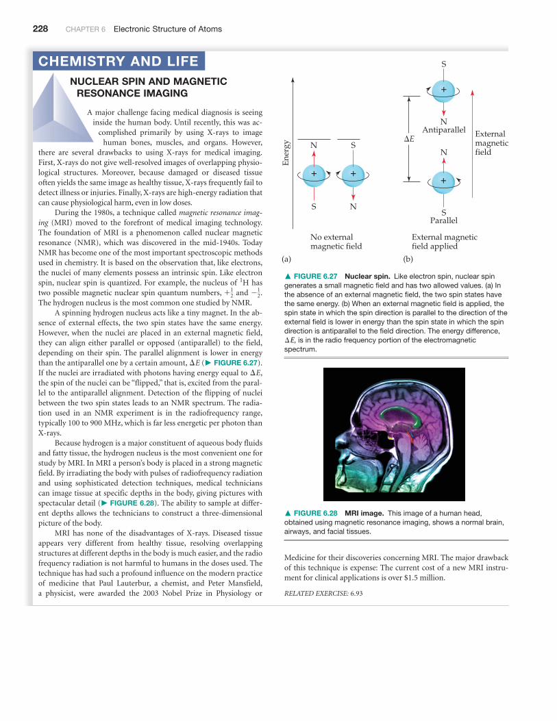
NUCLEAR SPIN AND MAGNETICRESONANCE IMAGING
A major challenge facing medical diagnosis is seeinginside the human body. Until recently, this was ac-
complished primarily by using X-rays to imagehuman bones, muscles, and organs. However,
there are several drawbacks to using X-rays for medical imaging.First, X-rays do not give well-resolved images of overlapping physio-logical structures. Moreover, because damaged or diseased tissueoften yields the same image as healthy tissue, X-rays frequently fail todetect illness or injuries. Finally, X-rays are high-energy radiation thatcan cause physiological harm, even in low doses.
During the 1980s, a technique called magnetic resonance imag-ing (MRI) moved to the forefront of medical imaging technology.The foundation of MRI is a phenomenon called nuclear magneticresonance (NMR), which was discovered in the mid-1940s. TodayNMR has become one of the most important spectroscopic methodsused in chemistry. It is based on the observation that, like electrons,the nuclei of many elements possess an intrinsic spin. Like electronspin, nuclear spin is quantized. For example, the nucleus of hastwo possible magnetic nuclear spin quantum numbers, and .The hydrogen nucleus is the most common one studied by NMR.
A spinning hydrogen nucleus acts like a tiny magnet. In the ab-sence of external effects, the two spin states have the same energy.However, when the nuclei are placed in an external magnetic field,they can align either parallel or opposed (antiparallel) to the field,depending on their spin. The parallel alignment is lower in energythan the antiparallel one by a certain amount, (� FIGURE 6.27).If the nuclei are irradiated with photons having energy equal to ,the spin of the nuclei can be “flipped,” that is, excited from the paral-lel to the antiparallel alignment. Detection of the flipping of nucleibetween the two spin states leads to an NMR spectrum. The radia-tion used in an NMR experiment is in the radiofrequency range,typically 100 to 900 MHz, which is far less energetic per photon thanX-rays.
Because hydrogen is a major constituent of aqueous body fluidsand fatty tissue, the hydrogen nucleus is the most convenient one forstudy by MRI. In MRI a person’s body is placed in a strong magneticfield. By irradiating the body with pulses of radiofrequency radiationand using sophisticated detection techniques, medical technicianscan image tissue at specific depths in the body, giving pictures withspectacular detail (� FIGURE 6.28). The ability to sample at differ-ent depths allows the technicians to construct a three-dimensionalpicture of the body.
MRI has none of the disadvantages of X-rays. Diseased tissueappears very different from healthy tissue, resolving overlappingstructures at different depths in the body is much easier, and the radiofrequency radiation is not harmful to humans in the doses used. Thetechnique has had such a profound influence on the modern practiceof medicine that Paul Lauterbur, a chemist, and Peter Mansfield,a physicist, were awarded the 2003 Nobel Prize in Physiology or
¢E¢E
-12+1
2
1H
CHEMISTRY AND LIFE
N
No externalmagnetic field
External magneticfield applied
(a) (b)
Externalmagneticfield
S
�
N
S
S
Antiparallel�E
�
S
N
N
Parallel
�
�
Ene
rgy
� FIGURE 6.27 Nuclear spin. Like electron spin, nuclear spingenerates a small magnetic field and has two allowed values. (a) Inthe absence of an external magnetic field, the two spin states havethe same energy. (b) When an external magnetic field is applied, thespin state in which the spin direction is parallel to the direction of theexternal field is lower in energy than the spin state in which the spindirection is antiparallel to the field direction. The energy difference,
, is in the radio frequency portion of the electromagneticspectrum.¢E
� FIGURE 6.28 MRI image. This image of a human head,obtained using magnetic resonance imaging, shows a normal brain,airways, and facial tissues.

SECTION 6.8 Electron Configurations 229
want to put more than one electron in an orbital and satisfy the Pauli exclusion principle,our only choice is to assign different values to the electrons. Because there are only twosuch values, we conclude that an orbital can hold a maximum of two electrons and they musthave opposite spins. This restriction allows us to index the electrons in an atom, giving theirquantum numbers and thereby defining the region in space where each electron is mostlikely to be found. It also provides the key to understanding the structure of the periodictable of the elements.
6.8 | ELECTRON CONFIGURATIONSArmed with knowledge of the relative energies of orbitals and the Pauli exclusion prin-ciple, we are in a position to consider the arrangements of electrons in atoms. The wayelectrons are distributed among the various orbitals of an atom is called the electronconfiguration of the atom.
The most stable electron configuration—the ground state—is that in which theelectrons are in the lowest possible energy states. If there were no restrictions on the pos-sible values for the quantum numbers of the electrons, all the electrons would crowdinto the ls orbital because it is the lowest in energy (Figure 6.24). The Pauli exclusionprinciple tells us, however, that there can be at most two electrons in any single orbital.Thus, the orbitals are filled in order of increasing energy, with no more than two electronsper orbital. For example, consider the lithium atom, which has three electrons. (Recallthat the number of electrons in a neutral atom equals its atomic number.) The ls orbitalcan accommodate two of the electrons. The third one goes into the next lowest energyorbital, the 2s.
We can represent any electron configuration by writing the symbol for the occupiedsubshell and adding a superscript to indicate the number of electrons in that subshell.For example, for lithium we write (read “ls two, 2s one”). We can also show thearrangement of the electrons as
In this representation, which we call an orbital diagram, each orbital is denoted by abox and each electron by a half arrow. A half arrow pointing up (_) represents an elec-tron with a positive spin magnetic quantum number and a half arrowpointing down (]) represents an electron with a negative spin magnetic quantum num-ber . This pictorial representation of electron spin, which corresponds to thedirections of the magnetic fields in Figure 6.25, is quite convenient.
Electrons having opposite spins are said to be paired when they are in the sameorbital (g). An unpaired electron is one not accompanied by a partner of opposite spin.In the lithium atom the two electrons in the 1s orbital are paired and the electron in the2s orbital is unpaired.
Hund’s RuleConsider now how the electron configurations of the elements change as we move fromelement to element across the periodic table. Hydrogen has one electron, which occu-pies the 1s orbital in its ground state:
The choice of a spin-up electron here is arbitrary; we could equally well show theground state with one spin-down electron. It is customary, however, to show unpairedelectrons with their spins up.
H
1s
: 1s1
(ms = -12)
(ms = +12)
Li
1s 2s
ls22s1
ms
230 CHAPTER 6 Electronic Structure of Atoms
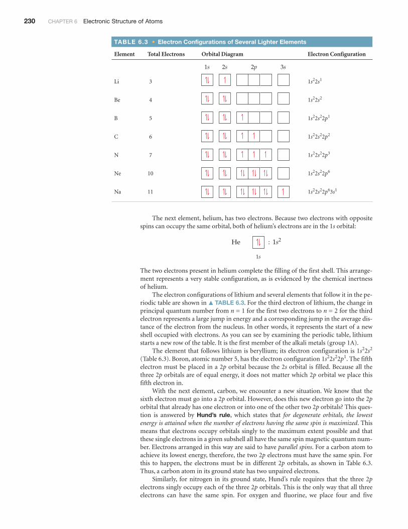
The next element, helium, has two electrons. Because two electrons with oppositespins can occupy the same orbital, both of helium’s electrons are in the 1s orbital:
The two electrons present in helium complete the filling of the first shell. This arrange-ment represents a very stable configuration, as is evidenced by the chemical inertnessof helium.
The electron configurations of lithium and several elements that follow it in the pe-riodic table are shown in � TABLE 6.3. For the third electron of lithium, the change inprincipal quantum number from n = 1 for the first two electrons to n = 2 for the thirdelectron represents a large jump in energy and a corresponding jump in the average dis-tance of the electron from the nucleus. In other words, it represents the start of a newshell occupied with electrons. As you can see by examining the periodic table, lithiumstarts a new row of the table. It is the first member of the alkali metals (group 1A).
The element that follows lithium is beryllium; its electron configuration is (Table 6.3). Boron, atomic number 5, has the electron configuration . The fifthelectron must be placed in a 2p orbital because the 2s orbital is filled. Because all thethree 2p orbitals are of equal energy, it does not matter which 2p orbital we place thisfifth electron in.
With the next element, carbon, we encounter a new situation. We know that thesixth electron must go into a 2p orbital. However, does this new electron go into the 2porbital that already has one electron or into one of the other two 2p orbitals? This ques-tion is answered by Hund’s rule, which states that for degenerate orbitals, the lowestenergy is attained when the number of electrons having the same spin is maximized. Thismeans that electrons occupy orbitals singly to the maximum extent possible and thatthese single electrons in a given subshell all have the same spin magnetic quantum num-ber. Electrons arranged in this way are said to have parallel spins. For a carbon atom toachieve its lowest energy, therefore, the two 2p electrons must have the same spin. Forthis to happen, the electrons must be in different 2p orbitals, as shown in Table 6.3.Thus, a carbon atom in its ground state has two unpaired electrons.
Similarly, for nitrogen in its ground state, Hund’s rule requires that the three 2pelectrons singly occupy each of the three 2p orbitals. This is the only way that all threeelectrons can have the same spin. For oxygen and fluorine, we place four and five
1s22s22p11s22s2
He
1s
: 1s2
2p 3s1s 2s
TABLE 6.3 • Electron Configurations of Several Lighter Elements
Element Total Electrons Orbital Diagram Electron Configuration
Li 3
Be 4
B 5
C 6
N 7
Ne 10
Na 11 1s22s22p63s1
1s22s22p6
1s22s22p3
1s22s22p2
1s22s22p1
1s22s2
1s22s1
SECTION 6.8 Electron Configurations 231
electrons, respectively, in the 2p orbitals. To achieve this, we pair up electrons in the 2porbitals, as we will see in Sample Exercise 6.7.
Hund’s rule is based in part on the fact that electrons repel one another. By occupy-ing different orbitals, the electrons remain as far as possible from one another, thusminimizing electron–electron repulsions.
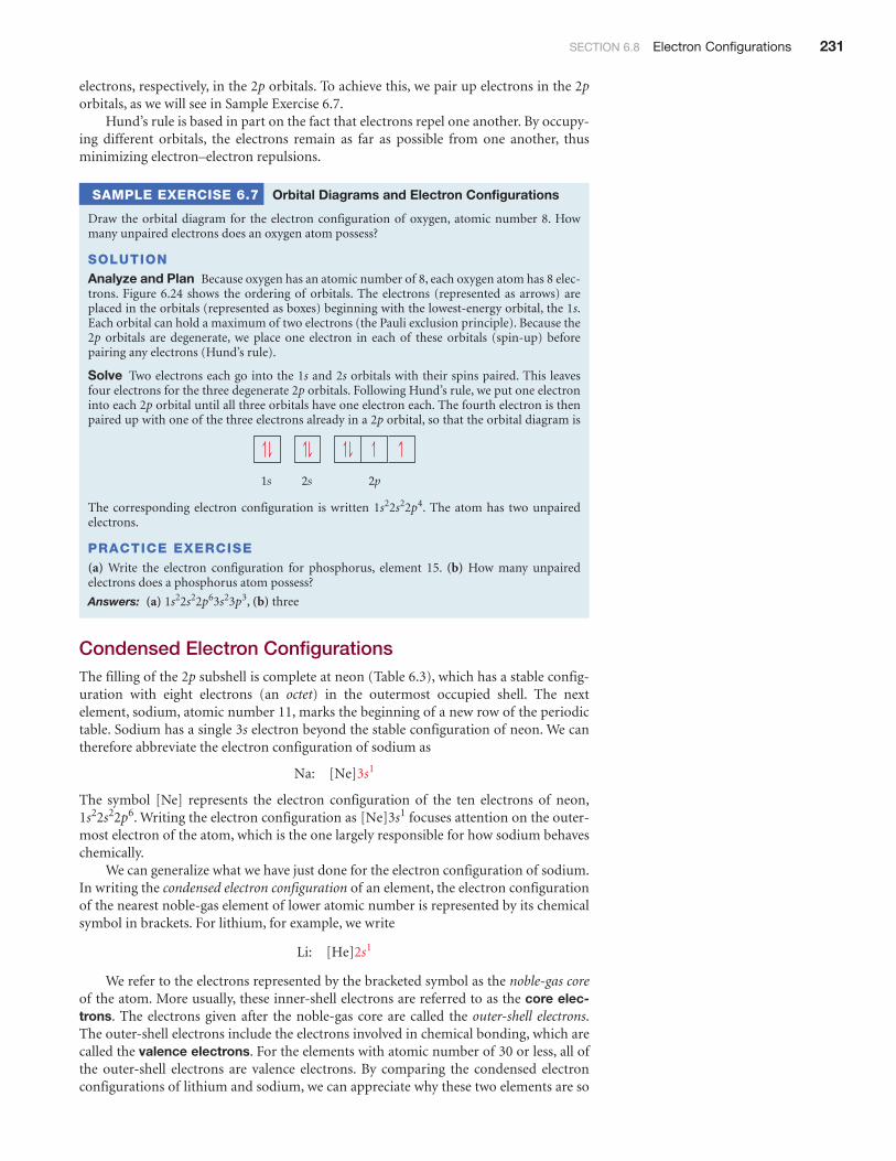
SAMPLE EXERCISE 6.7 Orbital Diagrams and Electron Configurations
Draw the orbital diagram for the electron configuration of oxygen, atomic number 8. Howmany unpaired electrons does an oxygen atom possess?
SOLUTIONAnalyze and Plan Because oxygen has an atomic number of 8, each oxygen atom has 8 elec-trons. Figure 6.24 shows the ordering of orbitals. The electrons (represented as arrows) areplaced in the orbitals (represented as boxes) beginning with the lowest-energy orbital, the 1s.Each orbital can hold a maximum of two electrons (the Pauli exclusion principle). Because the2p orbitals are degenerate, we place one electron in each of these orbitals (spin-up) beforepairing any electrons (Hund’s rule).
Solve Two electrons each go into the 1s and 2s orbitals with their spins paired. This leavesfour electrons for the three degenerate 2p orbitals. Following Hund’s rule, we put one electroninto each 2p orbital until all three orbitals have one electron each. The fourth electron is thenpaired up with one of the three electrons already in a 2p orbital, so that the orbital diagram is
The corresponding electron configuration is written . The atom has two unpairedelectrons.
PRACTICE EXERCISE(a) Write the electron configuration for phosphorus, element 15. (b) How many unpairedelectrons does a phosphorus atom possess?
Answers: (a) , (b) three
Condensed Electron ConfigurationsThe filling of the 2p subshell is complete at neon (Table 6.3), which has a stable config-uration with eight electrons (an octet) in the outermost occupied shell. The nextelement, sodium, atomic number 11, marks the beginning of a new row of the periodictable. Sodium has a single 3s electron beyond the stable configuration of neon. We cantherefore abbreviate the electron configuration of sodium as
The symbol [Ne] represents the electron configuration of the ten electrons of neon,. Writing the electron configuration as focuses attention on the outer-
most electron of the atom, which is the one largely responsible for how sodium behaveschemically.
We can generalize what we have just done for the electron configuration of sodium.In writing the condensed electron configuration of an element, the electron configurationof the nearest noble-gas element of lower atomic number is represented by its chemicalsymbol in brackets. For lithium, for example, we write
We refer to the electrons represented by the bracketed symbol as the noble-gas coreof the atom. More usually, these inner-shell electrons are referred to as the core elec-trons. The electrons given after the noble-gas core are called the outer-shell electrons.The outer-shell electrons include the electrons involved in chemical bonding, which arecalled the valence electrons. For the elements with atomic number of 30 or less, all ofthe outer-shell electrons are valence electrons. By comparing the condensed electronconfigurations of lithium and sodium, we can appreciate why these two elements are so
Li: [He]2s1
[Ne]3s11s22s22p6
Na: [Ne]3s1
1s22s22p63s23p3
1s22s22p4
1s 2s 2p

1A
3Li
[He]2s1
11Na
[Ne]3s1
19K
[Ar]4s1
37Rb
[Kr]5s1
55Cs
[Xe]6s1
87Fr
[Rn]7s1
Alkalimetals
� FIGURE 6.29 The outer-shellelectron configurations of the alkalimetals (group 1A in the periodic table).
232 CHAPTER 6 Electronic Structure of Atoms
similar chemically. They have the same type of electron configuration in the outermostoccupied shell. Indeed, all the members of the alkali metal group (1A) have a single svalence electron beyond a noble-gas configuration (� FIGURE 6.29).
Transition MetalsThe noble-gas element argon marks the end of the row started bysodium. The element following argon in the periodic table is potassium (K), atomicnumber 19. In all its chemical properties, potassium is clearly a member of the alkalimetal group. The experimental facts about the properties of potassium leave no doubtthat the outermost electron of this element occupies an s orbital. But this means that theelectron with the highest energy has not gone into a 3d orbital, which we might expect itto do. Because the 4s orbital is lower in energy than the 3d orbital (Figure 6.24), the con-densed electron configuration of potassium is
Following the complete filling of the 4s orbital (this occurs in the calcium atom),the next set of orbitals to be filled is the 3d. (You will find it helpful as we go along torefer often to the periodic table on the front inside cover.) Beginning with scandium andextending through zinc, electrons are added to the five 3d orbitals until they are com-pletely filled. Thus, the fourth row of the periodic table is ten elements wider than thetwo previous rows. These ten elements are known as either transition elements ortransition metals. Note the position of these elements in the periodic table.
In writing the electron configurations of the transition elements, we fill orbitals inaccordance with Hund’s rule—we add them to the 3d orbitals singly until all five or-bitals have one electron each and then place additional electrons in the 3d orbitals withspin pairing until the shell is completely filled. The condensed electron configurationsand the corresponding orbital diagram representations of two transition elements are asfollows:
Once all the 3d orbitals have been filled with two electrons each, the 4p orbitalsbegin to be occupied until the completed octet of outer electrons is reachedwith krypton (Kr), atomic number 36, another of the noble gases. Rubidium (Rb)marks the beginning of the fifth row. Refer again to the periodic table on the front insidecover. Notice that this row is in every respect like the preceding one, except that the valuefor n is greater by 1.
G I V E I T S O M E T H O U G H T
Based on the structure of the periodic table, which becomes occupied first, the6s orbital or the 5d orbitals?
The Lanthanides and ActinidesThe sixth row of the periodic table begins with one electron in the 6s orbital of cesium(Cs) and two electrons in the 6s orbital of barium (Ba). Notice, however, that the peri-odic table then has a break, with elements 57–70 placed below the main portion of thetable. This break point is where we begin to encounter a new set of orbitals, the 4f.
There are seven degenerate 4f orbitals, corresponding to the seven allowed values of, ranging from 3 to . Thus, it takes 14 electrons to fill the 4f orbitals completely.
The 14 elements corresponding to the filling of the 4f orbitals are known as either thelanthanide elements or the rare earth elements. These elements are set below the
-3ml
(4s24p6)
3d4s
Mn:
Zn:
or [Ar]
or [Ar]
[Ar]4s23d5
[Ar]4s23d10
K: [Ar]4s1
(1s22s22p63s23p6)
SECTION 6.9 Electron Configurations and the Periodic Table 233
other elements to avoid making the periodic table unduly wide. The properties of thelanthanide elements are all quite similar, and these elements occur together in nature.For many years it was virtually impossible to separate them from one another.
Because the energies of the 4f and 5d orbitals are very close to each other, the elec-tron configurations of some of the lanthanides involve 5d electrons. For example, theelements lanthanum (La), cerium (Ce), and praseodymium (Pr) have the followingelectron configurations:
Because La has a single 5d electron, it is sometimes placed below yttrium (Y) as thefirst member of the third series of transition elements; Ce is then placed as the firstmember of the lanthanides. Based on their chemistry, however, La can be considered thefirst element in the lanthanide series. Arranged this way, there are fewer apparentexceptions to the regular filling of the 4f orbitals among the subsequent members ofthe series.
After the lanthanide series, the third transition element series is completed by thefilling of the 5d orbitals, followed by the filling of the 6p orbitals. This brings us to radon(Rn), heaviest of the known noble-gas elements.
The final row of the periodic table begins by filling the 7s orbitals. The actinideelements, of which uranium (U, element 92) and plutonium (Pu, element 94) are thebest known, are then built up by completing the 5f orbitals. The actinide elements areradioactive, and most of them are not found in nature.
6.9 | ELECTRON CONFIGURATIONS AND THE PERIODIC TABLE
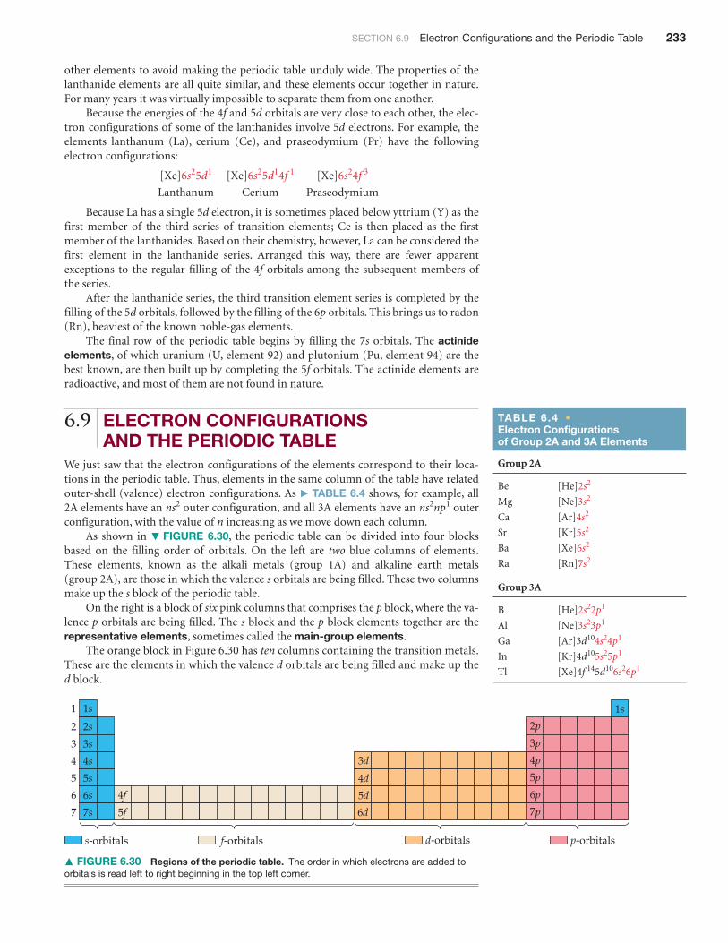
We just saw that the electron configurations of the elements correspond to their loca-tions in the periodic table. Thus, elements in the same column of the table have relatedouter-shell (valence) electron configurations. As � TABLE 6.4 shows, for example, all2A elements have an outer configuration, and all 3A elements have an outerconfiguration, with the value of n increasing as we move down each column.
As shown in � FIGURE 6.30, the periodic table can be divided into four blocksbased on the filling order of orbitals. On the left are two blue columns of elements.These elements, known as the alkali metals (group 1A) and alkaline earth metals(group 2A), are those in which the valence s orbitals are being filled. These two columnsmake up the s block of the periodic table.
On the right is a block of six pink columns that comprises the p block, where the va-lence p orbitals are being filled. The s block and the p block elements together are therepresentative elements, sometimes called the main-group elements.
The orange block in Figure 6.30 has ten columns containing the transition metals.These are the elements in which the valence d orbitals are being filled and make up thed block.
ns2np1ns2
[Xe]6s25d1 [Xe]6s25d14f 1 [Xe]6s24f 3
Lanthanum Cerium Praseodymium
TABLE 6.4 •Electron Configurations of Group 2A and 3A Elements
Group 2A
Be
Mg
Ca
Sr
Ba
Ra
Group 3A
B
Al
Ga
In
Tl [Xe]4f 145d106s26p1
[Kr]4d105s25p1
[Ar]3d104s24p1
[Ne]3s23p1
[He]2s22p1
[Rn]7s2
[Xe]6s2
[Kr]5s2
[Ar]4s2
[Ne]3s2
[He]2s2
1s
2s
3s
4s
5s
6s
7s
1
2
3
4
5
6
7
2p
3d
4f
5f
4d
5d
s-orbitals p-orbitalsf-orbitals d-orbitals
6d
3p
4p
5p
6p
7p
1s
� FIGURE 6.30 Regions of the periodic table. The order in which electrons are added toorbitals is read left to right beginning in the top left corner.

234 CHAPTER 6 Electronic Structure of Atoms
The elements in the two tan rows containing 14 columns are the ones in which thevalence f orbitals are being filled and make up the f block. Consequently, these elementsare often referred to as the f-block metals. In most tables, the f block is positionedbelow the periodic table to save space:
The number of columns in each block corresponds to the maximum number ofelectrons that can occupy each kind of subshell. Recall that 2, 6, 10, and 14 are the num-bers of electrons that can fill the s, p, d, and f subshells, respectively. Thus, the s block has2 columns, the p block has 6, the d block has 10, and the f block has 14. Recall also that lsis the first s subshell, 2p is the first p subshell, 3d is the first d subshell, and 4f is the first fsubshell, as Figure 6.30 shows. Using these facts, you can write the electron configura-tion of an element based merely on its position in the periodic table.
Let’s use the periodic table to write the electron configuration of selenium (Se, ele-ment 34). We first locate Se in the table and then move backward from it through thetable, from element 34 to 33 to 32 and so forth, until we come to the noble gas that pre-cedes Se. In this case, the noble gas is argon, Ar, element 18. Thus, the noble-gas core forSe is [Ar]. Our next step is to write symbols for the outer electrons. We do this by mov-ing across period 4 from K, the element following Ar, to Se:
Because K is in the fourth period and the s block, we begin with the 4s electrons, mean-ing our first two outer electrons are written . We then move into the d block, whichbegins with the 3d electrons. (The principal quantum number in the d block is alwaysone less than that of the preceding elements in the s block, as seen in Figure 6.30.) Tra-versing the d block adds ten electrons, . Finally we move into the p block, whoseprincipal quantum number is always the same as that of the s block. Counting thesquares as we move across the p block to Se tells us that we need four electrons, . Theelectron configuration for Se is therefore . This configuration can also bewritten with the subshells arranged in order of increasing principal quantum number:
.As a check, we add the number of electrons in the [Ar] core, 18, to the number of
electrons we added to the 4s, 3d, and 4p subshells. This sum should equal the atomicnumber of Se, 34: 18 + 2 + 10 + 4 = 34.
[Ar]3d104s24p3
[Ar]4s23d104p44p4
3d10
4s2
1A1
2
3
4
5
6
7
2A
4s2 4p43d10
3A 4A 5A
Noble-gas core
6A
Se
Ar
7A
8A
s d p
f
1A1
2
3
4
5
6
7
2A 3A 4A 5A 6A 7A
8A
s
d
p
f
SECTION 6.9 Electron Configurations and the Periodic Table 235
SAMPLE EXERCISE 6.8 Electron Configurations for a Group
What is the characteristic valence electron configuration of the group 7A elements, thehalogens?
SOLUTIONAnalyze and Plan We first locate the halogens in the periodic table, write the electron con-figurations for the first two elements, and then determine the general similarity between theconfigurations.
Solve The first member of the halogen group is fluorine (F, element 9). Moving backwardfrom F, we find that the noble-gas core is [He]. Moving from He to the element of next higheratomic number brings us to Li, element 3. Because Li is in the second period of the s block, weadd electrons to the 2s subshell. Moving across this block gives . Continuing to move to theright, we enter the p block. Counting the squares to F gives . Thus, the condensed electronconfiguration for fluorine is
The electron configuration for chlorine, the second halogen, is
From these two examples, we see that the characteristic valence electron configuration of ahalogen is , where n ranges from 2 in the case of fluorine to 6 in the case of astatine.
PRACTICE EXERCISEWhich family of elements is characterized by an electron configuration in the outer-most occupied shell?
Answer: group 4A
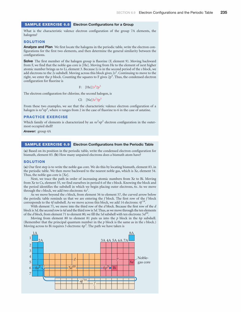
SAMPLE EXERCISE 6.9 Electron Configurations from the Periodic Table
(a) Based on its position in the periodic table, write the condensed electron configuration forbismuth, element 83. (b) How many unpaired electrons does a bismuth atom have?
SOLUTION(a) Our first step is to write the noble-gas core. We do this by locating bismuth, element 83, inthe periodic table. We then move backward to the nearest noble gas, which is Xe, element 54.Thus, the noble-gas core is [Xe].
Next, we trace the path in order of increasing atomic numbers from Xe to Bi. Movingfrom Xe to Cs, element 55, we find ourselves in period 6 of the s block. Knowing the block andthe period identifies the subshell in which we begin placing outer electrons, 6s. As we movethrough the s block, we add two electrons: .
As we move beyond the s block, from element 56 to element 57, the curved arrow belowthe periodic table reminds us that we are entering the f block. The first row of the f blockcorresponds to the 4f subshell. As we move across this block, we add 14 electrons: .
With element 71, we move into the third row of the d block. Because the first row of the dblock is 3d, the second row is 4d and the third row is 5d. Thus, as we move through the ten elementsof the d block, from element 71 to element 80, we fill the 5d subshell with ten electrons: .
Moving from element 80 to element 81 puts us into the p block in the 6p subshell.(Remember that the principal quantum number in the p block is the same as in the s block.)Moving across to Bi requires 3 electrons: . The path we have taken is
1A1
2
3
4
5
6
7
2A
6s2 6p35d10
4f 14
3A 4A 5A
Noble-gas core
6A
Bi
Xe
7A
8A
s d p
f
6p3
5d10
4f 14
6s2
ns2np2
ns2np5
Cl: [Ne]3s23p5
F: [He]2s22p5
2p52s2

236 CHAPTER 6 Electronic Structure of Atoms
Putting the parts together, we obtain the condensed electron configuration: .This configuration can also be written with the subshells arranged in order of increasing prin-cipal quantum number: .
Finally, we check our result to see if the number of electrons equals the atomic number ofBi, 83: Because Xe has 54 electrons (its atomic number), we have 54 + 2 + 14 + 10 + 3 = 83.(If we had 14 electrons too few, we would realize that we have missed the f block.)
(b) We see from the condensed electron configuration that the only partially occupied subshellis 6p. The orbital diagram representation for this subshell is
In accordance with Hund’s rule, the three 6p electrons occupy the three 6p orbitals singly, withtheir spins parallel. Thus, there are three unpaired electrons in the bismuth atom.
PRACTICE EXERCISEUse the periodic table to write the condensed electron configuration for (a) Co (element 27),(b) Te (element 52).
Answers: (a) or , (b) or
� FIGURE 6.31 gives, for all the elements, the ground-state electron configurationsfor the valence electrons. You can use this figure to check your answers as you practicewriting electron configurations. We have written these configurations with orbitals
[Kr]4d105s25p4[Kr]5s24d105p4[Ar]3d74s2[Ar]4s23d7
[Xe]4f 145d106s26p3
[Xe]6s24f 145d106p3
1A1
4Be2s2
1H1s1
3Li2s1
11Na3s1
19K4s1
21Sc
3d14s2
37Rb5s1
55Cs6s1
87Fr7s1
12Mg3s2
20Ca4s2
38Sr5s2
56Ba6s2
88Ra7s2
23V
3d34s2
41Nb
4d35s2
73Ta
4f 145d3
6s2
105Db
5f 146d3
7s2
39Y
4d15s2
57La
5d16s2
89Ac
6d17s2
22Ti
3d24s2
40Zr
4d25s2
72Hf
4f 145d2
6s2
104Rf
5f 146d2
7s2
2A2
3B3
4B4
5B5
6B6
7B7
3A13
4A14
5A15
6A16
7A17
8A18
[He]
[Ne]
[Ar]
[Kr]
[Xe]
[Rn]
[Xe]
[Rn]
Core
1B11
2B12
8 9
24Cr
3d54s1
42Mo
4d55s1
74W
4f 145d4
6s2
106Sg
5f 146d4
7s2
25Mn
3d54s2
43Tc
4d55s2
75Re
4f 145d5
6s2
5B
2s22p1
13Al
3s23p1
31Ga
3d104s2
4p1
49In
4d105s2
5p1
81Tl
4f 145d10
6s26p1
6C
2s22p2
14Si
3s23p2
32Ge
3d104s2
4p2
50Sn
4d105s2
5p2
82Pb
4f 145d10
6s26p2
7N
2s22p3
15P
3s23p3
33As
3d104s2
4p3
51Sb
4d105s2
5p3
83Bi
4f 145d10
6s26p3
8O
2s22p4
16S
3s23p4
34Se
3d104s2
4p4
52Te
4d105s2
5p4
84Po
4f 145d10
6s26p4
9F
2s22p5
17Cl
3s23p5
35Br
3d104s2
4p5
53I
4d105s2
5p5
85At
4f 145d10
6s26p5
2He1s2
10Ne
2s22p6
18Ar
3s23p6
36Kr
3d104s2
4p6
54Xe
4d105s2
5p6
86Rn
4f 145d10
6s26p6
71Lu
4f 145d1
6s2
103Lr
5f 146d1
7s2
70Yb
4f 146s2
102No
5f 147s2
69Tm
4f 136s2
101Md
5f 137s2
68Er
4f 126s2
100Fm
5f 127s2
67Ho
4f 116s2
99Es
5f 117s2
66Dy
4f 106s2
98Cf
5f 107s2
65Tb
4f 96s2
97Bk
5f 97s2
64Gd
4f 75d1
6s2
96Cm
5f 76d1
7s2
63Eu
4f 76s2
95Am5f 77s2
62Sm
4f 66s2
94Pu
5f 67s2
61Pm
4f 56s2
93Np
5f 46d1
7s2
60Nd
4f 46s2
92U
5f 36d1
7s2
59Pr
4f 36s2
91Pa
5f 26d1
7s2
58Ce
4f 15d1
6s2
90Th
6d27s2
26Fe
3d64s2
44Ru
4d75s1
76Os
4f 145d6
6s2
28Ni
3d84s2
46Pd4d10
78Pt
4f 145d9
6s1
29Cu
3d104s1
47Ag
4d105s1
79Au
4f 145d10
6s1
30Zn
3d104s2
48Cd
4d105s2
80Hg
4f 145d10
6s2
27Co
3d74s2
10
45Rh
4d85s1
77Ir
4f 145d7
6s2
8B
Metals
Lanthanideseries
Actinide series
Metalloids Nonmetals
107Bh
5f 146d5
7s2
108Hs
5f 146d6
7s2
109Mt
5f 146d7
7s2
109Mt
5f 146d7
7s2
110Ds
111Rg
112Cn
113 114 115 118116 117
� FIGURE 6.31 Valence electron configurations of the elements.
SECTION 6.9 Electron Configurations and the Periodic Table 237
listed in order of increasing principal quantum number. As we saw in Sample Exercise6.9, the orbitals can also be listed in order of filling, as they would be read off the peri-odic table.
Figure 6.31 allow us to reexamine the concept of valence electrons. Notice, for exam-ple, that as we proceed from to we add a completesubshell of 3d electrons to the electrons beyond the [Ar] core. Although the 3d electronsare outer-shell electrons, they are not involved in chemical bonding and are thereforenot considered valence electrons. Thus, we consider only the 4s and 4p electrons of Br tobe valence electrons. Similarly, if we compare the electron configurations of Ag (element47) and Au (element 79), we see that Au has a completely full subshell beyond itsnoble-gas core, but those 4f electrons are not involved in bonding. In general, for repre-sentative elements we do not consider the electrons in completely filled d or f subshells to bevalence electrons, and for transition elements we do not consider the electrons in a com-pletely filled f subshell to be valence electrons.
Anomalous Electron ConfigurationsThe electron configurations of certain elements appear to violate the rules we have justdiscussed. For example, Figure 6.31 shows that the electron configuration of chromium(element 24) is rather than the configuration we might expect.Similarly, the configuration of copper (element 29) is instead of .
This anomalous behavior is largely a consequence of the closeness of the 3d and 4sorbital energies. It frequently occurs when there are enough electrons to form preciselyhalf-filled sets of degenerate orbitals (as in chromium) or a completely filled d subshell(as in copper). There are a few similar cases among the heavier transition metals (thosewith partially filled 4d or 5d orbitals) and among the f-block metals. Although theseminor departures from the expected are interesting, they are not of great chemicalsignificance.
G I V E I T S O M E T H O U G H T
The elements Ni, Pd, and Pt are all in the same group. By examining the electronconfigurations for these elements in Figure 6.31, what can you conclude aboutthe relative energies of the nd and orbitals for this group?
SAMPLE INTEGRATIVE EXERCISE Putting Concepts Together
Boron, atomic number 5, occurs naturally as two isotopes, and , with natural abun-dances of and , respectively. (a) In what ways do the two isotopes differ from eachother? Does the electronic configuration of differ from that of (b) Draw the orbital di-agram for an atom of . Which electrons are the valence electrons? (c) Indicate three majorways in which the 1s electrons in boron differ from its 2s electrons. (d) Elemental boron reactswith fluorine to form , a gas. Write a balanced chemical equation for the reaction of solidboron with fluorine gas. (e) for (g) is . Calculate the standard en-thalpy change in the reaction of boron with fluorine. (f) When , also a gas at roomtemperature, comes into contact with water, the two react to form hydrochloric acid and boricacid, , a very weak acid in water. Write a balanced net ionic equation for this reaction.
SOLUTION(a) The two isotopes of boron differ in the number of neutrons in the nucleus. •(Sections2.3 and 2.4) Each of the isotopes contains five protons, but contains five neutrons, whereas
contains six neutrons. The two isotopes of boron have identical electron configurations,, because each has five electrons.
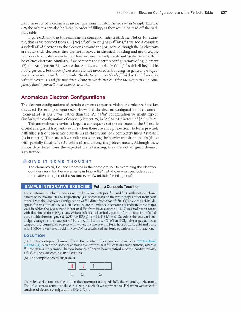
(b) The complete orbital diagram is
The valence electrons are the ones in the outermost occupied shell, the and electrons.The electrons constitute the core electrons, which we represent as [He] when we write thecondensed electron configuration, .[He]2s22p1
1s22p12s2
2p2s1s
1s22s22p1
11B
10B
H3BO3
BCl3
-1135.6 kJ>molBF3¢Hf°BF3
11B
11B?10B80.1%19.9%
11B10B
(n + 1)s
[Ar]3d94s2[Ar]3d104s1[Ar]3d44s2[Ar]3d54s1
4f 14
Br ([Ar]3d104s24p5)Cl ([Ne]3s23p5)
Related Documents