Quantachrome PoreMaster 60 SOP Page 1 of 41 Rev. No 2 https://rsc.aux.eng.ufl.edu SOP #: P-QMIP-01 Last Review/Update: 08/12/2020 1 Quantachrome PoreMaster 60 Standard Operating Procedure Rev. No. 2 by Gary Scheiffele & Caitlin Tibbetts Figure 1. Quantachrome PoreMaster 60 1. Purpose This standard operating procedure (SOP) is intended as a summary of basic instrument operation for the PoreMaster 60 shown in Figure 1. This includes safety, setup, sample loading, instrument settings, cell cleaning, sample disposal, and shutdown. This SOP does not supersede the Quantachrome operating manual. The full instrument manual includes theory, all cautions, and detailed explanations of parameters.

Welcome message from author
This document is posted to help you gain knowledge. Please leave a comment to let me know what you think about it! Share it to your friends and learn new things together.
Transcript

Quantachrome PoreMaster 60 SOP
Page 1 of 41 Rev. No 2
https://rsc.aux.eng.ufl.edu SOP #: P-QMIP-01
Last Review/Update: 08/12/2020
1
Quantachrome PoreMaster 60
Standard Operating Procedure
Rev. No. 2 by Gary Scheiffele & Caitlin Tibbetts
Figure 1. Quantachrome PoreMaster 60
1. Purpose
This standard operating procedure (SOP) is intended as a summary of basic instrument operation
for the PoreMaster 60 shown in Figure 1. This includes safety, setup, sample loading, instrument
settings, cell cleaning, sample disposal, and shutdown.
This SOP does not supersede the Quantachrome operating manual. The full instrument manual
includes theory, all cautions, and detailed explanations of parameters.

Quantachrome PoreMaster 60 SOP
Page 2 of 41 Rev. No 2
https://rsc.aux.eng.ufl.edu SOP #: P-QMIP-01
Last Review/Update: 08/12/2020
2
2. Overview
The PoreMaster 60 intrudes a non-wetting liquid (mercury) into pores over both a low-pressure
range (~0.2 psia to 50 psia) and a high-pressure range (0-60,000 psia). Volume intruded is
measured by the capacitance change as the length of a mercury column in a precision glass
capillary shortens. The Washburn equation relates the applied pressure to equivalent cylindrical
pore size given the mercury surface tension and contact angle. Thus the basic result is volume
intruded vs. pressure. This is converted to volume intruded vs. pore size. Pores are assumed to
be cylindrical for all basic calculations.
CAUTION CAUTION
Note: It is assumed that the liquid is also non-reactive. Thus, measurement should not be
attempted on materials that react with or dissolve in mercury. Small amounts of dissolved
material can significantly change the mercury contact angle and surface tension.
3. Prerequisites
Use of the PoreMaster 60 requires:
1. Becoming a user of MAIC/PAIC at https://maic.aux.eng.ufl.edu.
2. Requesting training through https://maic.aux.eng.ufl.
3. Reading the full instrument manual and this SOP.
4. Reading the mercury MSDS.
5. Successfully completing hands-on training under the supervision of MAIC/PAIC staff.
6. Samples that are inert in the presence of mercury.
4. Safety
4.1 PPE
• Safety glasses, nitrile gloves, and a disposable lab coat should be worn at all times when
operating the PoreMaster. A personal lab coat and storage container will be provided for
each user during safety training. Safety glasses and nitrile gloves are provided in Room
239.
4.2 Mercury
• The use of this instrument involves exposure to metallic mercury. As noted above, it is
required that the user is familiar with a mercury MSDS prior to use. There are also links
concerning metallic mercury in the reference section at the end of the document.
• The instrument housing is vented through the laboratory exhaust and all cleaning should
be done in the fume hood. As long as this is the case, exposure to vapor should be well
Quantachrome PoreMaster 60 SOP
Page 3 of 41 Rev. No 2
https://rsc.aux.eng.ufl.edu SOP #: P-QMIP-01
Last Review/Update: 08/12/2020
3
below the OSHA exposure limit. Any spills in these areas of more than 0.5 mL should be
reported to staff. Any spills outside these areas should be reported to staff immediately.
• To minimize mercury contamination, care should be taken to keep any containers of
mercury within or over the provided trays/containers. It is the user’s responsibility to
clean up stray mercury beads (even in the trays) prior to leaving the instrument. Small
beads can be cleaned by using painter’s tape to collect the beads and then folding the tape
to contain them. Larger beads that will not stick to tape, can be cleaned using the
handheld vacuum pump located in the main tray in the fume hood or simply rinsed into
the collection bottles from the trays.
• If desired, vapor monitors can be ordered at http://www.emt-
online.com/ProductPages/MercuryVapor.htm or similar sites.
4.3 Cryogen/Dewar
• Mercury is trapped from the vacuum system via a liquid nitrogen cold trap of ~0.5L. Fill
the trap wearing safety glasses and cryo gloves to protect against vacuum implosion if the
Dewar breaks.
4.4 Vacuum
• The instrument will pull a full vacuum (~10 mTorr) on your sample. Since the
penetrometers are glass, there is always a chance of breakage from residual flaws in the
glass. Always have the door to the low-pressure area closed when pulling vacuum on the
penetrometer.
4.5 Pressure
• To access the smallest pores, the PoreMaster applies up to 60,000 psia of pressure to the
penetrometer assembly. If a seal or rupture disk fails under pressure, a shock wave and
hydraulic oil mist will result (no mercury will be released). The user is responsible to
warn all lab occupants to wear safety glasses while the porosimeter is in use. If other
occupants do not comply, please contact staff before proceeding.
5. Procedure
5.1 Run Preparation
5.1.1 Area Preparation
• Both the PoreMaster table and fume hood cleaning area (Figure 2) should be clean and
ready for analysis. Cleaning materials (Kimwipes, paper towels, 409, ethanol), gloves,
waste containers, grease, and hydraulic oil should be ready. Waste containers should be
properly labeled.

Quantachrome PoreMaster 60 SOP
Page 4 of 41 Rev. No 2
https://rsc.aux.eng.ufl.edu SOP #: P-QMIP-01
Last Review/Update: 08/12/2020
4
• The tray on the far right is for clean parts, without mercury contamination, and holds the
penetrometers/cells, housing components for the cells, springs, and vacuum grease as
shown in Figure 3.
Figure 2. Cleaning station in fume hood
Figure 3. Clean tray with parts
Macro cell
Standard cell
Macro cell electrode
Macro cell housing
Macro cell housing top
Standard cell housing
Standard cell O-ring
Standard cell electrode
Spring for powder
samples
Vacuum grease
SS cylinders for blank
runs and small sample
runs.

Quantachrome PoreMaster 60 SOP
Page 5 of 41 Rev. No 2
https://rsc.aux.eng.ufl.edu SOP #: P-QMIP-01
Last Review/Update: 08/12/2020
5
5.1.2 Cold Trap Dewar and Vacuum Pump
• The cold trap (a “U” tube on the right side of the PoreMaster) is there to trap mercury
vapor before it reaches the vacuum pump oil. Before starting, remove the tube and clean,
making sure it is dry. Ethanol, a Kimwipe, and compressed air are all that is required.
• Once cleaned, replace the tube (check the O-rings for cracks once they are on the “U”
tube). Add liquid nitrogen to the cold trap Dewar such that after boiling ceases the Dewar
is ~3/4 full. Bring up to the “U” tube and cover tightly with aluminum foil.
• Turn on the vacuum pump (below the PoreMaster).
5.1.3 Cell Selection
• The penetrometer (or cell) is selected based primarily upon both the sample volume
(small, large, or macro) and the anticipated intruded volume in either the low- or high-
pressure range. Ideally either the low- or the high-pressure range will use 50-80% of the
stem volume (e.g. 1 to 1.6 cc for a 2 cc stem). A simple Archimedes density
measurement can provide a value for total open porosity. For a macro cell, the sample
volume must be at least half of the volume of the macro cell base (~8 cc) in order to fill
properly with mercury.
• A secondary consideration is sample homogeneity. The macro cell allows a much larger
sample volume and thus gives a better understanding of inhomogeneous samples. But if
the sample is highly porous (>2 cc of intrusion volume in either the low or high pressure
intrusion) sample size must be reduced.
5.1.4 Cell Assembly
• To begin, the cell should be clean and dry. No oil or residue from previous samples
should be present, otherwise the low-pressure station can be contaminated, and proper
vacuum will not be reached.
• Figure 4 details the components for the standard cell. The macro cell is similar, but has an
O-ring built into the top portion of the cell housing. For both types of cells, the etched (or
frosted) circle identifies the side of the cell in which the internal hook is upright. Figure 5
shows the internal hook for both the macro and standard cell. It is important to keep the
hook upright when testing powder materials that could be drawn through the
penetrometer as vacuum is applied.

Quantachrome PoreMaster 60 SOP
Page 6 of 41 Rev. No 2
https://rsc.aux.eng.ufl.edu SOP #: P-QMIP-01
Last Review/Update: 08/12/2020
6
Figure 4. PoreMaster short standard sample cell assembly
Figure 5. Internal hook in macro (left) and standard cell (right)
• Add the O-ring to the cell first, as shown in Figure 6.
• Add your sample.
• If the sample is a loose powder, add a spring to the sample compartment (pictured in
Figure 6). This provides electrical conduction through the sample, which will float and
pack against the electrode.
• Add a film of silicone vacuum grease to the rim of the cell that will be in contact with the
electrode. Make sure the entire rim has an even coating; when tapping your finger along
the rim, small peaks should form. If there is not enough grease, peaks will not form. If the
peaks are too large (falling over), then remove some grease.
Standard cell Upper cell housing
Etched/frosted circle
Electrode
O-ring
Internal hook

Quantachrome PoreMaster 60 SOP
Page 7 of 41 Rev. No 2
https://rsc.aux.eng.ufl.edu SOP #: P-QMIP-01
Last Review/Update: 08/12/2020
7
Figure 6. Assembling the cell: (a) adding the O-ring from the bottom, (b) adding the housing
from the bottom, and (c) securing the housing to the electrode
• Place the electrode against the rim and rotate at least 45 degrees. If you have a good seal,
you will be able to lift the cell vertically with one hand while supporting the cell with the
other as shown in Figure 7.
Figure 7. Checking seal on electrode
• Tighten the upper cell housing to the electrode with the spanner wrench. For normal
cells, apply 1/8 turn past initial resistance. For macro cells, apply ¼ turn past initial
resistance.
(a) (b) (c)

Quantachrome PoreMaster 60 SOP
Page 8 of 41 Rev. No 2
https://rsc.aux.eng.ufl.edu SOP #: P-QMIP-01
Last Review/Update: 08/12/2020
8
5.2 Low Pressure Analysis
5.2.1 Normal Cells
• A detailed image of the low pressure station is shown in Figure 8.
• Place the sample cell, with its housing in the low pressure (LP) station (Figure 9). Make
sure that the frosted circle is up to properly position the internal hook as seen in Figure 5.
Take care to turn slightly as the tip crosses the retaining O-ring. Back off a little if
resistance builds, and then proceed forward again. Maintain alignment along the length
of the cell so as to not break off or chip the cell tip! Once inserted, turn the black knurled
ring clockwise until tight to hold the cell in place.
• Either or both station(s) can be used; however, both must be sealed. If only one station is
in use, install the filler rod with cap into the other station. The filler rods should remain in
the LP stations when the stations/machine are not in use.
• Slide the cell retainer(s) over the cell(s) (or rod if only one station is used) and low
pressure port(s) and turn it (them) clockwise until the micro switch(es) click(s). The LP
Station indicator light will turn green when BOTH station micro switches are engaged.
• While holding the cell retainer, turn the cell retainer cap clockwise to tighten the cell in
place. Connect the signal cable to the signal cable connector on the cell retainer cap.
The cell retainers and cell retainer caps are interchangeable and can be used on either low
pressure station. However, the signal cable must be connected to its designated station
(the cables are labeled as 1 and 2). Make sure the door to the LP station is closed.
Figure 8. Detailed image of low pressure station

Quantachrome PoreMaster 60 SOP
Page 9 of 41 Rev. No 2
https://rsc.aux.eng.ufl.edu SOP #: P-QMIP-01
Last Review/Update: 08/12/2020
9
Figure 9. Low pressure station
5.2.2 Macro Cells
• To switch from normal cell to macro cell operation, first remove the cell retainer, cap,
and cable from Station 1. (Note that Station 2 cannot be used while Station 1 is in macro
cell mode.) Use the long hex wrench to turn the angle adjustment screw 27 turns
counterclockwise such that the post moves back far enough to clear the tab when the low
pressure assembly tilts as depicted in Figure 10 through Figure 12.
Slide cell assembly into
the LP station and turn
knurled ring clockwise
until the cell is tight in
place

Quantachrome PoreMaster 60 SOP
Page 10 of 41 Rev. No 2
https://rsc.aux.eng.ufl.edu SOP #: P-QMIP-01
Last Review/Update: 08/12/2020
10
Figure 10. Overhead view of changing angle adjustment screw for macro cell
Figure 11. Side view of changing angle adjustment screw for macro cell
Figure 12. Proper position with tilt for macro cell

Quantachrome PoreMaster 60 SOP
Page 11 of 41 Rev. No 2
https://rsc.aux.eng.ufl.edu SOP #: P-QMIP-01
Last Review/Update: 08/12/2020
11
• Check the tilt by clicking Operations/Manual Mode/Low Pressure, accept
responsibility, and then click on the valve, Vent/Cylinder. Check to make sure the
assembly is able to tilt without hitting the bolt/nut and then click Vent/Cylinder again to
return the assembly to its normal position. See Section 5.2.4 for dialog boxes showing
these steps.
• Insert the macro cell interlock (Figure 13). Turn clockwise to engage the micro switch.
Figure 13. Macro cell interlock
• Place the macro cell into the low pressure station. Again, take care to turn slightly as the
tip crosses the retaining O-ring. Back off a little if resistance builds, and then proceed
again. Maintain alignment along the length of the cell so as to not break off or chip the
cell tip! Once inserted, turn the black knurled ring clockwise until tight to hold the cell in
place.
• Although only Station 1 can be used, both stations must be sealed. Make sure Station 2 is
blanked with the filler rod and is capped.
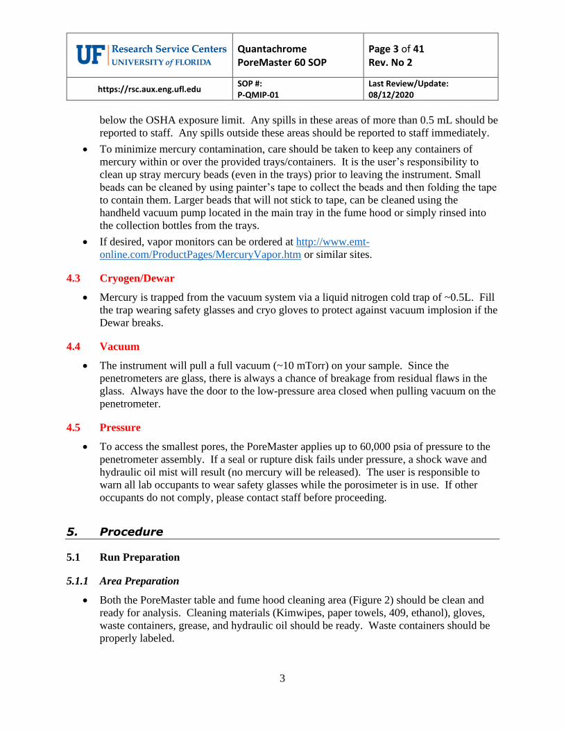
• Screw the macro cell retainer onto the macro cell interlock, making sure that the spring
goes over the post of the macro cell electrode as shown in Figure 14.
• Connect the Station 1 signal cable. Make sure the door to the LP station is closed.
Quantachrome PoreMaster 60 SOP
Page 12 of 41 Rev. No 2
https://rsc.aux.eng.ufl.edu SOP #: P-QMIP-01
Last Review/Update: 08/12/2020
12
Figure 14. Macro cell in low pressure station
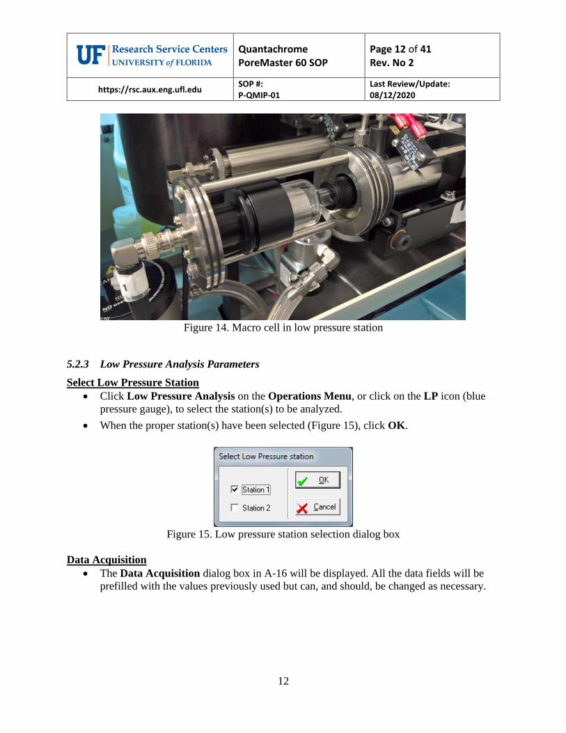
5.2.3 Low Pressure Analysis Parameters
Select Low Pressure Station
• Click Low Pressure Analysis on the Operations Menu, or click on the LP icon (blue
pressure gauge), to select the station(s) to be analyzed.
• When the proper station(s) have been selected (Figure 15), click OK.
Figure 15. Low pressure station selection dialog box
Data Acquisition
• The Data Acquisition dialog box in A-16 will be displayed. All the data fields will be
prefilled with the values previously used but can, and should, be changed as necessary.

Quantachrome PoreMaster 60 SOP
Page 13 of 41 Rev. No 2
https://rsc.aux.eng.ufl.edu SOP #: P-QMIP-01
Last Review/Update: 08/12/2020
13
Figure 16. Low pressure data acquisition dialog box
Note: A blank run correction may be applied in order to increase the already high accuracy of the
PoreMaster. Such a blank run can be used to correct for residual density and volume changes of mercury
due to temperature effects. In the ideal case, a blank run should be performed with a (control) sample
which is non-porous but of similar size (and of similar thermophysical properties) as the actual test
sample. The blank run (in the software called “blank cell correction”) should be performed under exactly
the same experimental conditions (e.g., same scan rate) as are employed for the actual test sample.
• Click Run Mode, Mercury Parameters, or Volume/Density Calculation to change any
of the operating parameters. Click Start to begin the analysis. All the various operating
parameters are described in more detail in Section 7.
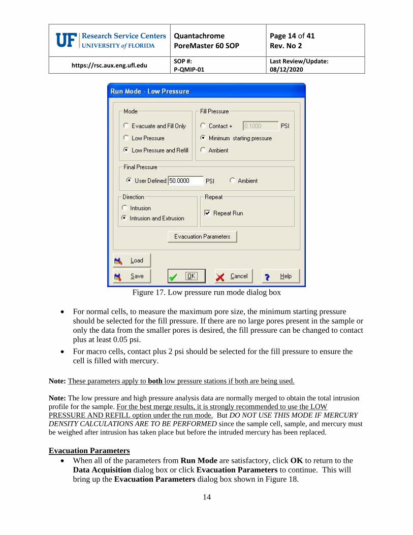
Run Mode
• To alter the low pressure operation, click Run Mode on the Data Acquisition dialog
box. The Run Mode dialog box will be displayed as shown in Figure 17.
Quantachrome PoreMaster 60 SOP
Page 14 of 41 Rev. No 2
https://rsc.aux.eng.ufl.edu SOP #: P-QMIP-01
Last Review/Update: 08/12/2020
14
Figure 17. Low pressure run mode dialog box
• For normal cells, to measure the maximum pore size, the minimum starting pressure
should be selected for the fill pressure. If there are no large pores present in the sample or
only the data from the smaller pores is desired, the fill pressure can be changed to contact
plus at least 0.05 psi.
• For macro cells, contact plus 2 psi should be selected for the fill pressure to ensure the
cell is filled with mercury.
Note: These parameters apply to both low pressure stations if both are being used.
Note: The low pressure and high pressure analysis data are normally merged to obtain the total intrusion
profile for the sample. For the best merge results, it is strongly recommended to use the LOW
PRESSURE AND REFILL option under the run mode. But DO NOT USE THIS MODE IF MERCURY
DENSITY CALCULATIONS ARE TO BE PERFORMED since the sample cell, sample, and mercury must
be weighed after intrusion has taken place but before the intruded mercury has been replaced.
Evacuation Parameters
• When all of the parameters from Run Mode are satisfactory, click OK to return to the
Data Acquisition dialog box or click Evacuation Parameters to continue. This will
bring up the Evacuation Parameters dialog box shown in Figure 18.

Quantachrome PoreMaster 60 SOP
Page 15 of 41 Rev. No 2
https://rsc.aux.eng.ufl.edu SOP #: P-QMIP-01
Last Review/Update: 08/12/2020
15
Figure 18. Low pressure evacuation parameters dialog box
• Evacuation occurs in two stages; fine and coarse. Fine evacuation is controlled by the
Evacuation Rate and lasts until either a set pressure or a set time. For solid pieces or
very coarse particles (those that will not fit through the cell stem hook) the set time can
be as short as 3 min. For fine powders, use a very slow evacuation rate and continue to
at least 1000 µm Hg (1000 mTorr) vacuum during fine evacuation. This will minimize
powder elutriation into the vacuum system. Similarly, for pore structures which could be
damaged by rapid pressure differentials, use a slow evacuation rate. Coarse evacuation
does not limit the draw from the pump and is used to achieve the 10 mTorr (10 µm Hg)
vacuum at the sample necessary for proper intrusion. However, 10 mTorr at the gauge is
not necessarily 10 mTorr at the sample; therefore, for a solid sample, coarse evacuation
should be at least 8 minutes.
Note: During the coarse evacuation the instrument fills the upper mercury reservoir.
• When all the Evacuation Parameters have been set, click OK to return to the Run
Mode dialog box. Then click OK to return to the Data Acquisition dialog box.
Mercury Parameters
• If it is necessary to change the constants for mercury, click Mercury Parameters. The
mercury parameters dialog box will be displayed (Figure 19).
• Click OK when all parameters are acceptable to return to the Data Acquisition dialog
box.

Quantachrome PoreMaster 60 SOP
Page 16 of 41 Rev. No 2
https://rsc.aux.eng.ufl.edu SOP #: P-QMIP-01
Last Review/Update: 08/12/2020
16
Figure 19. Mercury parameters dialog box
Volume/Density Calculations
• Click on the Volume/Density Calculation button if the volume and density of the
sample are required. If normalization by volume has been requested, it will be necessary
to enter the sample volume or do the calculations. The Volume/Density Calculation
dialog box will be displayed as shown in Figure 20. NOTE: This dialog box is also
accessible through the Data Reduction Menu.
Note: If normalization is to be done by weight and the density of the sample is not of interest, the
sample weight only needs to be entered in the Data Acquisition dialog box.
• For ease of operation, the calculation buttons are numbered. In order to prevent
producing erroneous results, the buttons should be selected in their numerical order. Click
OK when all parameters are acceptable to return to the Data Acquisition dialog box.
Figure 20. Volume/density calculation dialog box

Quantachrome PoreMaster 60 SOP
Page 17 of 41 Rev. No 2
https://rsc.aux.eng.ufl.edu SOP #: P-QMIP-01
Last Review/Update: 08/12/2020
17
• From the Data Acquisition dialog box, start the low pressure analysis by clicking on the
Start button as shown in Figure 16. (OK will save the setting but not start the run.) As
the low pressure evacuation run progresses, the PC will display a series of messages
showing the status of the analysis. Pressure vs. cumulative volume intruded plots will
also be displayed for each station used. When the analysis is complete, the data will be
uploaded from each station used and saved to disk.
5.2.4 Manual Mode
• As mentioned above for macro cell operation, at times it is useful to view the instrument
status under Operations/Manual Mode/Low Pressure. A disclaimer will appear that
must be accepted before proceeding (Figure 21).
• Clicking the lower left valve (Vent/Cylinder), highlighted in green in Figure 22, will
cause the low pressure station to tilt. Make sure both LP stations are sealed before
opening the valve.
• Adjustments (other than tilt) should not be made in Manual Mode without prior approval
from staff.
Figure 21. Disclaimer dialog box

Quantachrome PoreMaster 60 SOP
Page 18 of 41 Rev. No 2
https://rsc.aux.eng.ufl.edu SOP #: P-QMIP-01
Last Review/Update: 08/12/2020
18
Figure 22. Manual mode low pressure dialog box
Note: that the Station 1 and Station 2 numbers are mV signals and do not signify anything. The
50 PSIA Transducer and Vacuum Gauge values are useful to watch.
5.3 High Pressure Analysis
5.3.1 Cell/Penetrometer Preparation
• Once the low pressure/mercury fill run has completed, bring the “After LP Analysis” 500
mL wide mouth bottle from the fume hood to the low pressure station.
• Remove the signal cable, cell retainer, and loosen the black knurled nut to release the
pressure on the O-ring.
• Remove the cell from the low pressure station, taking care to maintain alignment until
the cell is completely out of the low pressure station to avoid breaking or chipping the tip.
• Place the cell vertically in the transfer bottle, electrode at the bottom, and transfer to the
hood or balance. (If measuring density, tare the bottle and weigh the
cell+sample+mercury.)
• Use a 1 mL syringe with pipetting needle (labeled mercury) to add/or remove pure
mercury so that the level is 1-2 cm from the stem. If any air pockets form, remove them
via the red winding wire.
Valve to
select to
check tilt

Quantachrome PoreMaster 60 SOP
Page 19 of 41 Rev. No 2
https://rsc.aux.eng.ufl.edu SOP #: P-QMIP-01
Last Review/Update: 08/12/2020
19
• Use a 5 mL syringe (no rubber gasket) with pipetting needle (labeled hydraulic oil) to fill
the stem with hydraulic oil above the mercury.
• For precise head pressure calculation, one can measure the mercury height above the
Delrin housing as shown in Figure 23.
• For normal cells, add the metal jacket as shown in Figure 24. The short cells employ the
spacer as well as the jacket.
• Transfer the cell to the bottle with hydraulic oil and gently, vertically oscillate the
assembly within the oil pool to help fill all voids and eliminate air bubbles surrounding
the electrode housing.
• Transfer the cell in the bottle with oil to the high pressure chamber for cell loading.
Figure 23. Mercury height above Delrin housing for head pressure calculation
Short Sample
Compartment Cell
Long Sample
Compartment Cell

Quantachrome PoreMaster 60 SOP
Page 20 of 41 Rev. No 2
https://rsc.aux.eng.ufl.edu SOP #: P-QMIP-01
Last Review/Update: 08/12/2020
20
Figure 24. Normal cells with metal housing for high pressure chamber
5.3.2 Cell Placement in High Pressure Chamber
• The high pressure (HP) chamber should be loosely closed after the previous run. Open,
and check that there is no debris or mercury at the bottom of the chamber.
• All the parts that are used in the high pressure chamber are exposed to oil, and it is not
necessary to clean them after each run. To keep the parts clean from debris, they are
stored and covered in a metal tray to the right of the PoreMaster as shown in Figure 25.
During transfer of parts, keep the tray next to the hydraulic chamber opening to minimize
the spread of oil (Figure 26).
• The capacitance sheath is used for all cells.
Metal housings act as
capacitance sheaths
for HP analysis
Weight for short
normal cells
Threaded spacer
connected to Delrin
LP cell housing

Quantachrome PoreMaster 60 SOP
Page 21 of 41 Rev. No 2
https://rsc.aux.eng.ufl.edu SOP #: P-QMIP-01
Last Review/Update: 08/12/2020
21
Figure 25. High pressure components
Normal Cells
• If a macro cell had been used last, add the Normal Cell Housing to the high pressure
chamber. There is only one threaded hole on the end for the placement tool – use this for
proper vertical orientation. Also remove ~5 mL of oil via pipetting needle/syringe found
in the upper left compartment of the PoreMaster.
• Attach the spacer to the capacitance sheath and thread onto Delrin housing, then add the
weight for the short, normal cells (see Figure 24).
• Lower the assembled cell/sheath/spacer/weight slowly into the hydraulic chamber.
Macro Cells
• If a normal cell had been used last, remove the Normal Cell Housing via the placement
tool and place in the metal tray. Also add ~5 mL of oil via pipetting needle/syringe found
in the upper left compartment of the PoreMaster.
• Lower the assembled macro cell slowly into the hydraulic chamber.
• Using the placement tool, gently lower the Macro Cell Housing over the macro cell,
being careful that the housing does not rotate while lowering. (Again, there is only one
possible hole for the placement tool.)
• Carefully slide the capacitance sheath over the cell stem (Figure 26). Maintain alignment
so that the cell end is not broken or chipped.
Macro Cell Housing
Normal Cell Housing
Capacitance Sheath – all cells
Short Cell
Spacer
Housing
Placement Tool
Weight

Quantachrome PoreMaster 60 SOP
Page 22 of 41 Rev. No 2
https://rsc.aux.eng.ufl.edu SOP #: P-QMIP-01
Last Review/Update: 08/12/2020
22
Figure 26. Macro cell in high pressure chamber
5.3.3 Closing the High Pressure Chamber
• Make sure that the vent valve is open by clicking on Load/Unload HP Cavity, dialog
box shown in Figure 27, on the Operations drop-down menu. The message under the
START OIL button should read Vent Open before proceeding.
• Rotate the upper housing clockwise until it is aligned over the cell.
• Inspect the O-ring/seal for flaws
• Lift up to unlock the housing, then guide down gently over the cell/capacitance sheath.
• Engage the threads, then turn ~8.5 full turns clockwise until there is a hard stop. There
may be some resistance as the seal engages.
• If there is steadily increasing resistance – STOP. Either the vent valve is not open, or
there is too much oil in the chamber, or the O-ring/seal is damaged.
Figure 27. Load/unload HP cavity dialog box
5.3.4 High Pressure Analysis Parameters
Data Acquisition
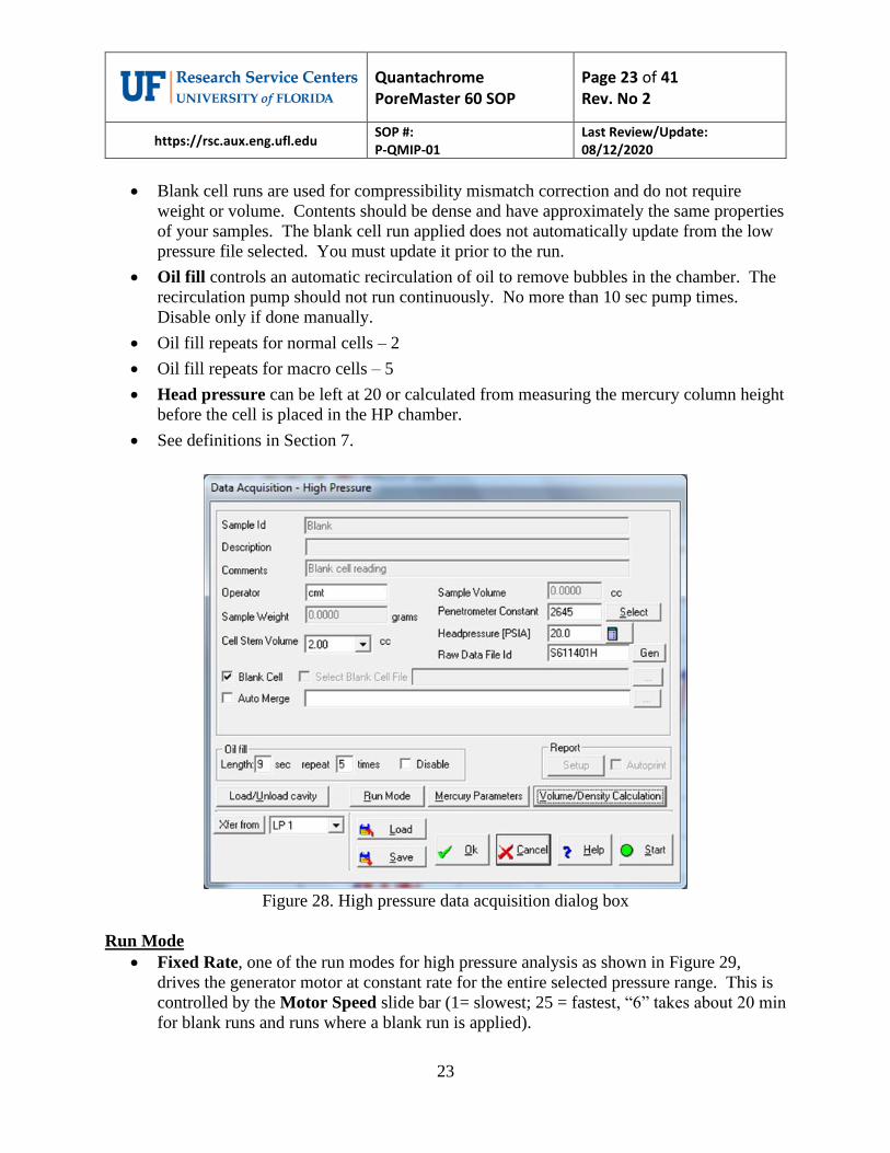
• Populating this dialog box (Figure 28) is best accomplished by clicking the “Xfer from”
tab in the bottom left. Data can be transferred from either of the low pressure stations.
• Auto Merge selects a low pressure file to merge with the high pressure run and populates
the fields. This and “Xfer from” are mutually exclusive.
Quantachrome PoreMaster 60 SOP
Page 23 of 41 Rev. No 2
https://rsc.aux.eng.ufl.edu SOP #: P-QMIP-01
Last Review/Update: 08/12/2020
23
• Blank cell runs are used for compressibility mismatch correction and do not require
weight or volume. Contents should be dense and have approximately the same properties
of your samples. The blank cell run applied does not automatically update from the low
pressure file selected. You must update it prior to the run.
• Oil fill controls an automatic recirculation of oil to remove bubbles in the chamber. The
recirculation pump should not run continuously. No more than 10 sec pump times.
Disable only if done manually.
• Oil fill repeats for normal cells – 2
• Oil fill repeats for macro cells – 5
• Head pressure can be left at 20 or calculated from measuring the mercury column height
before the cell is placed in the HP chamber.
• See definitions in Section 7.
Figure 28. High pressure data acquisition dialog box
Run Mode
• Fixed Rate, one of the run modes for high pressure analysis as shown in Figure 29,
drives the generator motor at constant rate for the entire selected pressure range. This is
controlled by the Motor Speed slide bar (1= slowest; 25 = fastest, “6” takes about 20 min
for blank runs and runs where a blank run is applied).

Quantachrome PoreMaster 60 SOP
Page 24 of 41 Rev. No 2
https://rsc.aux.eng.ufl.edu SOP #: P-QMIP-01
Last Review/Update: 08/12/2020
24
• Autospeed drives the pressure at the rate selected on the slide bar until a volume change
(intrusion or extrusion) takes place. The speed is then automatically reduced in
proportion to the rate of change in the volume. This allows the PoreMaster to provide the
best resolution in the range(s) where pores are located without wasting time scanning at
slow speeds when no volume change is detected. – Normal Mode
• Step-Wise allows you to select specific pressures (pore sizes) at which the data will be
acquired. If you select this mode, you must specify the Step-Wise Parameters by
selecting the Dwell Time and Select Points (Figure 30). (See Section 7 for details.)
• When Fixed Rate or Autospeed is selected, the starting and ending pressures can be
specified. The start pressure must be lower than the end pressure. The operator can also
select whether the analysis consists of only intrusion data or intrusion and extrusion. The
number of Repeat analyses (0 or 1) can also be selected.
Note: Repeat analyses can be done only if intrusion AND extrusion are selected.
Figure 29. High pressure run mode dialog box

Quantachrome PoreMaster 60 SOP
Page 25 of 41 Rev. No 2
https://rsc.aux.eng.ufl.edu SOP #: P-QMIP-01
Last Review/Update: 08/12/2020
25
Figure 30. Select points for step-wise parameters dialog box
Run Start
• When all parameters in the Data Acquisition dialog box for high pressure and associated
Run Mode, Mercury Parameters, and Volume/Density Calculations dialog boxes (the
last two are the same as low pressure) have been confirmed, start the run by clicking the
green dot Start tab.
5.3.5 Cell Removal
• At the completion of a run, open the vent valve again by clicking on Load/Unload HP
Cavity on the Operations drop-down menu. The message under the START OIL button
should read Vent Open before proceeding (Figure 27).
• Unscrew the HP cavity seal. You may need to use the opening wrench to assist in the
initial loosening of the seal. Continue to unscrew the assembly until the threads are no
longer engaged. Lift the upper end cap until it latches in the “UP” position, swing it out
of the way to the right side (over the petri dish lid). Make sure the high pressure parts
tray is near the opening for the chamber to reduce oil spillage. Carefully remove the
capacitance sheath from the cell, again maintaining alignment so that the stem does not
break or chip.
• For normal cells, remove weight and spacers and transfer the cell to the 500 mL “After
HP” wide mouth bottle. For macro cells, remove the macro cell housing first by using
the placement tool (after removing the sheath) as shown in Figure 31, and then place the
cell in the bottle for transport. Place all the parts directly into the metal tray, avoiding
drips. Then cover the tray and put it back on the right side of the PoreMaster.

Quantachrome PoreMaster 60 SOP
Page 26 of 41 Rev. No 2
https://rsc.aux.eng.ufl.edu SOP #: P-QMIP-01
Last Review/Update: 08/12/2020
26
• Inspect O-ring and backup ring for signs of wear. Contact staff for replacement. Inspect
interior for broken glass and spilled mercury. Contact staff if either is evident.
• Transfer the cell in the 500 mL WM bottle to the fume hood for cleaning.
Figure 31. Removing macro cell sheath and housing from the high pressure chamber
5.4 Troubleshooting
• There is an extensive table on problems/solutions in the instrument manual. What
follows are cases that are not covered in that table.
5.4.1 Abort Run
• Click on STOP at the top of the screen (on the PC), or ABORT at the bottom of the data
acquisition window. If both low pressure and high pressure runs are in progress at the
same time, select which run to abort from the message box as shown in Figure 32. A
high pressure run can also be aborted by pressing the EMERGENCY STOP button
located on the deck panel.
Figure 32. Abort run dialog box

Quantachrome PoreMaster 60 SOP
Page 27 of 41 Rev. No 2
https://rsc.aux.eng.ufl.edu SOP #: P-QMIP-01
Last Review/Update: 08/12/2020
27
Note: If a run is aborted, sometimes the instrument/computer communications are disrupted. To
be safe, after a run is aborted, reboot the computer and software, and turn off the PoreMaster and
turn it back on. Go to manual mode and check that all pressures have returned to ambient before
starting further runs.
5.4.2 Finishing Mercury Fill
• If this error message appears, the most likely explanation is that there is not enough
mercury in the lower reservoir. It is also possible that there is mercury in the upper low
pressure station trap. Report error to staff so that both chambers can be checked.
5.5 Cleanup
• There are three trays in the fume hood as shown in Figure 33. All are polypropylene and
are thus resistant to mercury, oil, ethanol, and detergent. The left tray is for primary
cleaning. The middle tray is for cell prep (Hg addition/subtraction, oil addition). The
right tray contains only clean items that may still have ethanol drying from
crevices/threads/etc. All are contained in a secondary containment tray, so any spills
inside a tray can be rinsed into a waste bottle and the rinsing can still be done within
containment. Wear gloves and lab coat for all cleaning procedures.
Figure 33. Cleaning stations
Primary Cleaning Tray
Transfer/Cell Prep Tray
Tools and Drying Tray
Clean Hg
Clean Oil
Transfer Bottles
Hg Waste
Containers

Quantachrome PoreMaster 60 SOP
Page 28 of 41 Rev. No 2
https://rsc.aux.eng.ufl.edu SOP #: P-QMIP-01
Last Review/Update: 08/12/2020
28
• Once a cell has been brought from the hydraulic chamber, 409 (or other grease cutting
detergent) is used to remove the bulk of the hydraulic oil from the assembly as shown in
Figure 34.
• The cell is then inverted over the “Mercury for Recycle” bottle (Figure 34).
• The electrode retaining assemble is removed, lifting the stem briefly from within the
bottle as shown in Figure 34.
• Mercury is released by sliding the electrode off center until a gap appears as shown in
Figure 34. This will allow the bulk of the mercury to drain into the recycle bottle.
Note: Do not let the 250 mL Mercury Recycle bottle become more than 2/3 full.
Figure 34. Cleaning the cell: (a) removing bulk of oil from the outside, (b) removing housing,
and (c) sliding electrode off to drain mercury into the recycle container
• Bring the cell to a horizontal position with the sample end over the recycle container. If
the sample is a solid piece, use a finger to keep the sample within the cell and pour the
rest of the mercury into the recycle bottle from the sample end.
• Place the contaminated sample into the Mercury Hazardous Waste container. This
container should be labeled from the start of use, and should contain only
paper/gloves/tape, mercury, water/detergent, and ethanol/oil in addition to samples.
There is only one mercury waste landfill, and they will not accept solvents like acetone or
toluene.
• Use the ethanol wash bottle to rinse any remaining mercury and oil into the Mercury
Hazardous Waste container, employing Kimwipes for any stubborn residue.
• Rinse the electrode and associated housing assembly off into the same container.
• Wipe dry and blow off all components with compressed air. Look carefully for
remaining oil, and repeat if necessary. All clean components are returned to the tray on
the right, including the spanner wrench.
(a) (b) (c)
Quantachrome PoreMaster 60 SOP
Page 29 of 41 Rev. No 2
https://rsc.aux.eng.ufl.edu SOP #: P-QMIP-01
Last Review/Update: 08/12/2020
29
• If a milky film (from small sample particles) forms on the cell, it can be removed by
using the pipe cleaner or sonicating – contact staff for instruction for sonication if the
pipe cleaner does not work.
6. Reporting
6.1 Data Processing on Workstation
• There is a UF site license for the use of the software. For UF internal users that have
installed the Porowin software on their computer, the contents of C:/QCData/PWconfig
must be copied from the instrument computer to have the correct calibration data. This
allows the data to be recalculated if necessary (missing densities, weights, etc.).
6.2 Report Multiview
• Go to Options, select Tabular Data Options and make sure that “Print one out of every
“1” data points” is selected. If this is not done, the entire data set will not be exported.
• After opening a file (displaying a Raw Volume vs. Pressure Plot) right click in the plot
area to bring up the options box (Figure 35) and select Report Setup as shown in Figure
36. Add your desired tables/graphs from the lists of available tables and graphs as shown
in Figure 37. There is also the option to save the user’s preference to load quickly for the
next report.

Quantachrome PoreMaster 60 SOP
Page 30 of 41 Rev. No 2
https://rsc.aux.eng.ufl.edu SOP #: P-QMIP-01
Last Review/Update: 08/12/2020
30
Figure 35. Options box
Figure 36. Report setup dialog box

Quantachrome PoreMaster 60 SOP
Page 31 of 41 Rev. No 2
https://rsc.aux.eng.ufl.edu SOP #: P-QMIP-01
Last Review/Update: 08/12/2020
31
• Example of generally accepted basic reports/graphs: standard report summary, pore size
distribution by volume for both intrusion and extrusion, and graphs of volume and Dv(r)
vs. pore size as selected in Figure 37.
Figure 37. Report setup dialog box with basic tables/graphs selected
• The reports/graphs will appear in cascading windows on the screen such that the last on
the list will be on the top of the stack as shown in Figure 38.
Figure 38. Selected tables/graphs opened from report setup

Quantachrome PoreMaster 60 SOP
Page 32 of 41 Rev. No 2
https://rsc.aux.eng.ufl.edu SOP #: P-QMIP-01
Last Review/Update: 08/12/2020
32
• Right click on each window and select Save as Report. This will save with a “.prp” file
extension, which is simply an ASCII text file. The files can be opened in Notepad or
Word using the “all files” function, but the tables can also be imported into Excel for
further analysis.
• In Excel: Select Open, All files, and pick the desired .prp file. This will open the Text
Import Wizard (Figure 39).
Figure 39. Text import wizard step 1 dialog box
• Either Delimited or Fixed Width can be selected, but the import must be started at the
appropriate row to get the data or the header plus data. For the example in Figure 38, the
data begins on row 24.
• For “character” column delimiters, select Tab, Space, and Treat consecutive
delineators as one (Figure 40). Make sure the lines are separating the data into
appropriate columns.

Quantachrome PoreMaster 60 SOP
Page 33 of 41 Rev. No 2
https://rsc.aux.eng.ufl.edu SOP #: P-QMIP-01
Last Review/Update: 08/12/2020
33
Figure 40. Text import wizard step 2 dialog box
• All the other calculations done in the PoreMaster program can be calculated in Excel
from the volume intrusion and extrusion data. Publication quality plots will usually be
done in an external program. See the full manual for the appropriate equations. The
values from the program can be used to make sure the equations were entered correctly
into Excel.
6.3 Editing Analysis Information or Data
• If data needs to be truncated or a weight or name needs to be updated, these can be
edited. Again, right click the main “Raw Volume vs. Pressure” and select either
Analysis Information or Edit Raw Data or Tags as shown in Figure 41. In the dialog
box (Figure 42) make whatever changes are necessary and then save the file with the
changes.

Quantachrome PoreMaster 60 SOP
Page 34 of 41 Rev. No 2
https://rsc.aux.eng.ufl.edu SOP #: P-QMIP-01
Last Review/Update: 08/12/2020
34
Figure 41. Options box highlighting options for editing a file
Figure 42. Analysis information dialog box
6.4 Raw Data
• The raw data files, “.prm” files, can be opened with Notepad, but note that the data has
not been adjusted for penetrometer constants.

Quantachrome PoreMaster 60 SOP
Page 35 of 41 Rev. No 2
https://rsc.aux.eng.ufl.edu SOP #: P-QMIP-01
Last Review/Update: 08/12/2020
35
7. Definitions
7.1 General
7.1.1 Data Acquisition Dialog Box
Sample Id: A sample identification name or number can be entered into this field. Twenty
characters are allowed.
• Description and Comments are the fields to display any comments or important notes
about the sample or analysis. These fields allow a maximum of 40 characters each.
• Operator displays the operator's name. This field allows a maximum of 30 characters.
• Sample Weight in grams is usually entered prior to the start of the analysis.
• Cell Stem Volume will toggle between the values 2.0 and 0.5 cc. Select the value that
reflects the penetrometer that is being used.
• Sample Volume: This value can be changed by the operator if the volume of the
sample (in cc) is known, or it can be calculated. If normalization is to be done by
weight and the density of the sample is not of interest, this field can be ignored.
• Penetrometer Constant in mV/cc is the calibration value of the sample cell. The
value supplied with the instrument can be used (and is recommended) or a value
determined by calibrating the sample cell can be entered. A value can also be
selected from the table of stored values by clicking Select. When Select is used,
only the constants appropriate to the station being loaded will be displayed.
Calibration constants specific to a given glass cell are not required for routine
analyses.
• Raw Data File Id displays the name of the file that holds the raw porosimetry
data. The filename ends with the extension .PRM. This file contains the
information necessary to do recalculations at a later time. The default filename
displayed is encoded to contain useful information. For example:
S5930011.PRM
Where: S = Sample
5 = the last number of the year, e.g. 2015 (6 for 2016)
9 = the month, September (1-9 represent the first nine months and A-C
represent months 10-12)
30 = the day of the month, day 30 of September
01 = the analysis number for the day, 01 is the first analysis of the day
1 = represents the station the sample is in (1 is for low pressure station 1,
2 is for low pressure station 2, and A is for high pressure)
Note: Up to 99 samples a day can be run in each station with this automatic encoding scheme.
Each time a run is completed in each station, the number is automatically incremented.

Quantachrome PoreMaster 60 SOP
Page 36 of 41 Rev. No 2
https://rsc.aux.eng.ufl.edu SOP #: P-QMIP-01
Last Review/Update: 08/12/2020
36
Note: If a different filename is desired, any valid DOS filename may be used. It can be no longer
than 8 characters (not including the extension .PRM). Only numbers and characters can be used.
Spaces and reserved characters such as ‘?’ or ‘*’ are not allowed.
• Gen is used to regenerate the automatic filename id in the event it was changed by the
user.
• Blank Cell: Check this box to perform a blank cell (empty cell) measurement.
When this box is checked, all of the fields in the Data Acquisition window will be
grayed out with the exception of the Operator, Cell Stem Volume, Raw Data File
Id, and Penetrometer Constant entry fields. Also, the Sample Volume and Sample
Weight entry fields will be automatically set to zero. After the blank cell
measurement is completed, the raw data file is stored in the C:\QCdata\Porodata
folder. A blank run for each station and cell type can be kept in the folder and
selected for the correction without having to run a blank analysis each time.
• Select Blank Cell File: If desired, a blank cell correction can be applied to an
analysis. This will subtract the data of a blank cell run from the sample data. If a
user wants to perform a measurement with the blank cell correction, check this box
then select the blank cell file from the correct folder.
Note: If a raw file that was not run as a blank is selected, the screen will display “Invalid
blank run file”. (Blank cell files have an entry of zero in the Sample Volume field and this
is the run parameter that the software uses when differentiating between sample
measurement files and blank cell files). Click on the “…” button to the right to re-open the
folder if a different blank file needs to be selected.
• Xfer from allows the user to populate the fields from the other stations.
7.1.2 Mercury Parameters Dialog Box
• Surface Tension: The allowable surface tension ranges from 400.00 to 550.00 ergs/cm2.
A value outside this range will result in the previous value being redisplayed. 480 is
recommended.
• Contact Angle: The valid range for the contact angle is from 90.01 to 179.99 degrees.
Any value outside this range will result in the previous value being redisplayed. The
extrusion contact angle must be equal to, or less than, the intrusion contact angle. 140 is
recommended for both as initial values.
7.1.3 Volume/Density Calculation Dialog Box
• Mercury Density: In order to calculate the volume and density of the sample the density
of mercury at ambient temperature must be provided. If known, it can be entered in the
field provided. If it is not known, enter the Ambient Temperature and click on the
Calculate Mercury Density button. The program will calculate the density of mercury.
• Weight of Empty Cell allows the weight of the fully assembled empty cell to be entered.
The weight of the cell always refers to a completely assembled cell-housing, including

Quantachrome PoreMaster 60 SOP
Page 37 of 41 Rev. No 2
https://rsc.aux.eng.ufl.edu SOP #: P-QMIP-01
Last Review/Update: 08/12/2020
37
the upper cell housing, cell contact assembly, O-ring, and vacuum grease. Use the same
parts for each weighing.
• Weight of Cell and Hg is the weight of the fully assembled cell filled completely with
mercury.
• Weight of Cell, Sample, and Hg is the weight of the fully assembled cell after loading it
with the sample and filling with mercury. Since this weight is a function of the fill, the
refill option in Low Pressure runs should not be used when determining sample densities.
Note: The weight of the Cell and Sample can also be measured and input to Calculate Sample
Weight or the sample can be weighed before assembly and entered into Sample Weight.
• Calculate Sample Volume will calculate the volume of the sample and all pores not
intruded at fill pressure.
• Calculate Density will calculate the bulk density of the sample in g/cc. The bulk density
is defined as the sample density determined by the volume of mercury displaced at fill
pressure.
7.2 Low Pressure Run Parameters
7.2.1 Run Mode Dialog Box
Mode – defines how the low pressure station will be used.
• Evacuate and Fill Only is used to simply fill a sample cell in preparation for a high
pressure analysis without recording any intrusion/extrusion data.
• Low Pressure performs a low pressure analysis up to the final requested pressure, up to a
maximum of 50 PSIA. Upon completion of the analysis, the station(s) are returned to
ambient pressure.
• Low Pressure and Refill is the same as the Low Pressure mode selection except that
after the analysis, the cell is re-evacuated and refilled in preparation for a high pressure
analysis.
Fill Pressure – defines the pressure at which a low pressure analysis will begin.
• Contact fills the sample cell until mercury contact with the base plate electrode is
detected plus a user selected value (usually 0.1 to 0.2 psi) to insure that the sample cell is
completely filled before starting the low pressure analysis. For macro cells, contact plus 2
psi should be selected.
• Minimum Starting Pressure will start analysis at about 0.2 psi.
• Ambient will fill the sample cell to ambient pressure.
Final Pressure
• This is the maximum pressure for a low pressure analysis. It may be Ambient or a User
Defined pressure up to 50 psia (50 psia is recommended).

Quantachrome PoreMaster 60 SOP
Page 38 of 41 Rev. No 2
https://rsc.aux.eng.ufl.edu SOP #: P-QMIP-01
Last Review/Update: 08/12/2020
38
Direction
• This instructs the PoreMaster to do either just an Intrusion or a combined Intrusion and
Extrusion analysis.
Repeat
• This allows the user to select 0 or 1 repeated scan on the same sample. These will be
performed as a single analysis and will create a single data file. See SPLIT FILE in Data
Reduction Section.
7.2.2 Evacuation Parameters Dialog Box
Evacuation Rate
• Ranges from slow (1) for fine powders to fast (10) for solid samples.
Fine Evacuation Until:
• This is controlled by the Evacuation Rate and lasts until either a set pressure or set time.
Coarse Evacuation Until:
• This stage of evacuation does not limit the draw from the pump and is used to achieve the
15 mTorr vacuum for intrusion. A set pressure or set time is also specified.
7.3 High Pressure Run Parameters
7.3.1 Data Acquisition Dialog Box
• Auto Merge can be selected to automatically merge the high pressure analysis with a
previously run low pressure analysis.
• Oil Fill: This specifies the number of times and length of each time the oil pump is
turned on to ensure bubbles are not trapped in the line.
Headpressure
• When performing a low pressure analysis, the stem is horizontal. However, upon transfer
to the high pressure cavity, the cell is vertical. This causes additional pressure due to the
hydrostatic head of mercury. To achieve greater precision (particularly in the low
pressure region of the high pressure analysis), enter the actual initial pressure in the
Headpressure (PSIA). The “head pressure” value is the sum of the ambient pressure
(local barometric pressure found at local airport web site) plus the pressure corresponding
to the weight of the column of mercury and is set to 20 psia by default.
• For convenience, a “Headpressure Calculator” is provided. To use the calculator, first
measure the height of the mercury column from its meniscus to the center of the bulb
portion of the penetrometer while the cell is in the upright position.
• Click the Calculator button next to the Headpressure (PSIA) field and enter the
measured height, in millimeters, in the new field provided. Click OK for the software to
calculate the actual head pressure (assuming atmospheric pressure is 14.7 psia) and
automatically enter it into the Headpressure (PSIA) field.

Quantachrome PoreMaster 60 SOP
Page 39 of 41 Rev. No 2
https://rsc.aux.eng.ufl.edu SOP #: P-QMIP-01
Last Review/Update: 08/12/2020
39
7.3.2 Load/Unload Cavity Dialog Box
• This opens the vent valve for the high pressure chamber and allows the user to start and
stop the oil pump manually.
7.3.3 Run Mode Dialog Box
Mode
• Fixed Rate drives the generator motor at constant rate for the entire selected pressure
range. This is controlled by the Motor Speed slide bar (1 = slowest; 25 = fastest).
• Autospeed drives the pressure at the rate selected on the slide bar until a volume change
(intrusion or extrusion) takes place. The speed is then automatically reduced in
proportion to the rate of change in the volume. This allows the PoreMaster to provide the
best resolution in the range(s) where pores are located without wasting time scanning at
slow speeds when no volume change is detected. This is the normal mode.
• Step-Wise allows you to select specific pressures (pore sizes) at which the data will be
acquired. If you select this mode, you must specify the Step-Wise Parameters as well.
Motor Speed
• The motor speed slide bar controls the Fixed Rate mode with 1 being the slowest and 25
being the fastest setting.
Pressure Range (PSIA)
• This allows the user to specify the Start Pressure and End Pressure with the maximum
range being 20 to 60,000 psi.
Step-Wise Parameters
• Step-Wise mode allows the user to select specific pressures (pore sizes) at which the data
will be acquired.
• If this mode is selected, the user must first specify Dwell Time (the time for which the
PoreMaster holds a desired pressure before advancing to the rest) from 0 to 999 seconds
– a value between 10 to 30 seconds is appropriate for most samples. A long dwell time
will unnecessarily slow the entire analysis. Next the user must specify the pressure values
required.
• Click on Select Points. Fill in the Range and Number of Points fields after deciding
whether the points are to be selected by pressure or pore size.
• Then click on Generate Intrusion Points and/or Generate Extrusion Points. Points
not separated by at least one pound will not be generated. A maximum of 2000 points
can be selected. Individual points can be added to the end of the list, inserted within the
list, edited, or deleted by clicking on the appropriate buttons at the bottom of the dialog
box. All the points can be deleted at once by clicking on Delete All.

Quantachrome PoreMaster 60 SOP
Page 40 of 41 Rev. No 2
https://rsc.aux.eng.ufl.edu SOP #: P-QMIP-01
Last Review/Update: 08/12/2020
40
8. Negligence
It is expected from all authorized users of this instrument to follow appropriate and safe
operational procedures in the manipulation of components and operation of the system.
Oversight or negligence in the operation and use of this instrument will lead to PI notification.
Negligence will result in re-training and removal of machine access if not corrected.
What is negligence - Quantachrome PoreMaster 60
(NRF Room 239)
1) BREAKAGE OF THE GLASS POROSIMETER CELLS (~$300-350 ea)
[Exception: breakage by failure of hydraulic seals at high pressure]
• Everything contacting the penetrometer assemblies during transport or cleaning is
plastic. Dropping the cell in such a way that it chips, or breaks is considered
negligence.
• When inserting or removing penetrometers from the low pressure stations, or when
inserting or removing metal sheaths for the high pressure station, be sure to maintain
linear alignment until the sheath is completely removed. It is very easy to break the
end of the cell by tilting the metal sheath just at the end of removal.
• Breakage of penetrometers due to negligence will result in loss of right to use
penetrometers purchased by NRF.
2) DAMAGE CAUSED BY USING EXCESSIVE FORCE
• Avoid excessive force when opening or closing the hydraulic chamber. As covered in
training, we do not want to break off posts or damage the threads of the high pressure
chamber seal (probable loss of instrument). Need for excessive force is most
commonly due to the presence of pressure in the chamber. This must be released
before proceeding. Other possible causes are misalignment or worn o-rings and/or
backup rings (check with staff if not obvious).
• Damage caused by using excessive force will result in immediate suspension of
machine access.
3) NOT USING PROPER CHEMICAL HYGIENE
• Users must notify staff if their sample contains any metals that may be dissolved by
mercury. Staff will arrange a separate waste mercury container, so the sample does
not contaminate the main mercury supply.

Quantachrome PoreMaster 60 SOP
Page 41 of 41 Rev. No 2
https://rsc.aux.eng.ufl.edu SOP #: P-QMIP-01
Last Review/Update: 08/12/2020
41
• EPA/DEP fines for things like (1) uncapped or unlabeled waste containers, (2) spills
that are not cleaned up (mercury, oil, etc.) immediately after the occurrence are not
part of the rate calculation. The staff is not there to clean up after you.
• If a user is not following proper chemical hygiene, the user and PI will be notified.
The user will be required to assist staff with cleanup immediately after the
occurrence, before using the machine again.
If you have any questions or concerns regarding the statements above, please contact a member
of the center’s staff for clarification.
I have read and understand the Negligence in Equipment Operation Statement
and the Critical Safety Reminders for the operation of this instrument.
AGREE □ NOT AGREE □
Please contact staff for a printed copy of the Negligence Form to be signed and added to your
profile.
Related Documents