UC Berkeley UC Berkeley Electronic Theses and Dissertations Title Engineering Lipid Vesicles for Cellular Reconstitution Permalink https://escholarship.org/uc/item/0hq5d9jr Author Richmond, David Publication Date 2011 Peer reviewed|Thesis/dissertation eScholarship.org Powered by the California Digital Library University of California

Welcome message from author
This document is posted to help you gain knowledge. Please leave a comment to let me know what you think about it! Share it to your friends and learn new things together.
Transcript
UC BerkeleyUC Berkeley Electronic Theses and Dissertations
TitleEngineering Lipid Vesicles for Cellular Reconstitution
Permalinkhttps://escholarship.org/uc/item/0hq5d9jr
AuthorRichmond, David
Publication Date2011 Peer reviewed|Thesis/dissertation
eScholarship.org Powered by the California Digital LibraryUniversity of California
Engineering Lipid Vesicles for Cellular Reconstitution
By
David Laurence Richmond
A dissertation submitted in partial satisfaction of the
requirements for the degree of
Doctor of Philosophy
in
Biophysics
in the
Graduate Division
of the
University of California, Berkeley
Committee in charge:
Professor Daniel A. Fletcher, Chair Professor Phillip Geissler
Professor Jay Groves Professor David Drubin
Spring 2011

Engineering Lipid Vesicles for Cellular Reconstitution
© 2011
By David Laurence Richmond
1
Abstract
Engineering Lipid Vesicles for Cellular Reconstitution
by
David Laurence Richmond
Doctor of Philosophy in Biophysics
University of California, Berkeley
Professor Daniel A. Fletcher, Chair
The reductionist approach to modern cell biology aims to identify the individual
molecules and interactions that give rise to complex biological activity. A complementary constructionist approach, known as reconstitution, aims to recapitulate biological structures and functions from basic building blocks in order to show which components are essential and how biophysical constraints, such as membrane boundaries, influence organization and activity. My dissertation research has applied and extended this ‘bottom-up’ approach to study the role of membrane mechanics in the formation of cellular filopodia and to develop new tools for reconstituting processes encapsulated within membranes and for engineering cell-like devices.
We investigated the mechanics of actin-membrane interactions by studying dendritic actin networks grown on the surface of giant unilamellar vesicles. In this minimal system, we observed the formation of parallel filament protrusions arising from the highly branched dendritic actin network, notably in the absence of bundling proteins. We confirmed through a simple theoretical model that a lipid bilayer can drive the emergence of bundled actin filament protrusions from branched actin filament networks, thus playing a role normally attributed to actin-binding proteins. This revealed a critical role for the membrane in organizing actin filaments at the plasma membrane. This work motivated the development of a technique for encapsulating protein contents in the lumen of lipid vesicles in order to emulate the biophysical boundary conditions of real cells. We demonstrated the use of a microfluidic jet to form lipid vesicles with controlled contents by deforming a planar bilayer. These vesicles mimic an
2
essential organizational feature of cells – encapsulation within a lipid membrane – and provide a platform for more complex cellular reconstitution. Subsequently, we adapted this technique to a pulsed inkjet-based device, enabling greater control of vesicle size and improved throughput. Using this inkjet-based device for vesicle formation, we were able to control membrane properties such as asymmetric lipid composition and insertion of membrane proteins, which are essential for numerous cellular processes. We demonstrated the applicability of this technique by reconstituting SNARE-mediated membrane fusion in a geometry that mimics exocytosis.
In summary, this work has provided new insight into the role of lipid bilayer mechanics on the reconstitution of cellular protrusions and developed a novel technique that enables formation of lipid vesicles with controlled contents and membrane properties. Further development of this technique will enable advanced reconstitution experiments and construction of functional cell-like devices for medical and biomaterials applications.

i
This dissertation is dedicated to my wife,
Virginia Amelia Richmond
ii
Table of Contents Acknowledgments ............................................................................................................ vi Chapter 1: Introduction to Cellular Reconstitution ..................................................... 1
1.1 Overview ..............................................................................................................................2 1.2 Lipid Membranes in Biology..............................................................................................3
1.2.1 Composition of Biological Membranes.........................................................................3 1.2.2 Organization of Lipid Membranes.................................................................................5 1.2.3 Physical Properties of Lipid Membranes.......................................................................6 1.2.4 Model Lipid Membranes ...............................................................................................8
1.3 The Actin Cytoskeleton.......................................................................................................9
1.3.1 Actin and Actin Binding Proteins................................................................................10 1.3.2 Mechanics of Actin Filaments .....................................................................................11
1.4 Actin-Membrane Interactions and Cell Motility ...........................................................12
1.4.1 The Dendritic Nucleation Model of Cell Motility .......................................................12 1.4.2 The Convergent Elongation Model of Filopodia Formation .......................................14
1.5 Cellular Reconstitution.....................................................................................................16
1.5.1 Encapsulation for Cellular Reconstitution...................................................................17 1.5.2 Engineering Cell-like Devices .....................................................................................20
1.6 Scope of Thesis...................................................................................................................22
Chapter 2: Membrane-Induced Bundling of Actin Filaments .................................. 23
2.1 Abstract ..............................................................................................................................24 2.2 Introduction .......................................................................................................................24 2.3 Results and Discussion......................................................................................................25 2.4 Conclusions ........................................................................................................................31 2.5 Materials and Methods .....................................................................................................32
2.5.1 Protein Expression, Purification, and Fluorescent Labeling........................................32 2.5.2 GUV Formation ...........................................................................................................32 2.5.3 In vitro Reconstitution of Thin Actin Filament Protrusions ........................................32 2.5.4 Microscopy ..................................................................................................................33 2.5.5 Data Analysis and Modeling........................................................................................33 2.5.6 Image Processing .........................................................................................................33
iii
2.6 Supplementary Information.............................................................................................34 2.6.1 Initiation of Filament Bundling by an Elastic Membrane ...........................................34 2.6.2 Membrane Tension Dependence on Membrane-Induced Bundling ............................35 2.6.4 Growth Dynamics of Parallel Filament Protrusions ....................................................40 2.6.5 Linescan Analysis of Arp2/3 and NWASP within Parallel Filament Protrusions........41 2.6.6 Fluorescence Recovery of Photobleaching of Actin along a Parallel Filament Protrusion...............................................................................................................................42 2.6.7 Conditions for Experiments Shown in Figures............................................................42
2.7 Acknowledgments .............................................................................................................43
Chapter 3: Unilamellar Vesicle Formation and Encapsulation by Microfluidic Jetting............................................................................................................................... 44
3.1 Abstract ..............................................................................................................................45 3.2 Introduction .......................................................................................................................45 3.3 Results and Discussion......................................................................................................46 3.4 Conclusions ........................................................................................................................58 3.5 Materials and Methods .....................................................................................................59
3.5.1 Solutions Used in the Jet Device .................................................................................59 3.5.2 Planar Bilayer Formation.............................................................................................59 3.5.3 Vesicle Characterization ..............................................................................................59 3.5.4 Glass Micronozzle Fabrication ....................................................................................60 3.5.5 Piezoelectric Jet Device ...............................................................................................60 3.5.6 Imaging ........................................................................................................................60 3.5.7 Estimation of Protrusion and Vortex Velocity ............................................................61
3.6 Supplementary Information.............................................................................................61
3.6.1 Estimation of Bulus Kinetic Energy, membrane Protrusion Free Energy, and Lipid Tube Free Energy...................................................................................................................61 3.6.2 Formation of Water-Oil-Water Emulsions Instead of Unilamellar Vesicles...............62
3.7 Acknowledgments .............................................................................................................62
Chapter 4: Inkjet Formation of Unilamellar Lipid Vesicles for Cell-like Encapsulation .................................................................................................................. 64
4.1 Abstract ..............................................................................................................................65 4.2 Introduction .......................................................................................................................65 4.3 Results and Discussion......................................................................................................67
4.3.1 Formation of Single Unilamellar Lipid Vesicles with Multiple Pulses of an Inkjet ...67
iv
4.3.2 Control of Vesicle Formation using Inkjet Parameters ...............................................70 4.3.3 Formation of Cell-Sized Vesicles through Variation of Fluid Viscosity.....................71 4.3.4 High-Throughput Inkjet Formation of Vesicles ..........................................................74 4.3.5 Real-Time Assembly and Interrogation of Actin Networks Inside Vesicles...............76
4.4 Conclusions ........................................................................................................................78 4.5 Materials and Methods .....................................................................................................79
4.5.1 Reagents.......................................................................................................................79 4.5.2 Rheometry....................................................................................................................79 4.5.3 Inkjet Device and Vesicle Formation ..........................................................................79 4.5.4 Planar Bilayer Lipid Membranes.................................................................................80 4.5.5 Actin Network Polymerization ....................................................................................80
4.6 Acknowledgments .............................................................................................................81
Chapter 5: Forming Giant Vesicles with Controlled Membrane Composition, Asymmetry, and Contents.............................................................................................. 82
5.1 Abstract ..............................................................................................................................83 5.2 Introduction .......................................................................................................................83 5.3 Results and Discussion......................................................................................................84
5.3.1 Formation of GUVs with Controlled Lipid Composition............................................84 5.3.2 Formation of GUVs with Asymmetric Membranes ....................................................87 5.3.3 Incorporation of Transmembrane Proteins and Control of Orientation in GUVs .......88 5.3.4 Reconstitution of Membrane Fusion in GUVs ............................................................92
5.4 Conclusions ........................................................................................................................96 5.5 Materials and Methods .....................................................................................................97
5.5.1 SUV Preparation ..........................................................................................................97 5.5.2 Protein Expression .......................................................................................................97 5.5.3 Proteo-Liposome Preparation ......................................................................................99 5.5.4 Chamber Design ..........................................................................................................99 5.5.5 Planar Bilayer Formation...........................................................................................100 5.5.6 GUV Formation by Microfluidic Jetting ...................................................................100 5.5.7 Incorporating TMR-PIP2 into GUVs .........................................................................101 5.5.8 Asymmetric DGS-NTA-Ni GUV Experiment ..........................................................101 5.5.9 tSNARE Incorporation and Functional SNARE Complex Formation ......................101 5.5.10 Syb-GFP Incorporation and Orientation..................................................................102 5.5.11 Analysis of TM Protein Orientation ........................................................................102 5.5.12 SUV-GUV Fusion Experiment................................................................................103 5.5.13 Analysis of SUV-GUV Fusion Events ....................................................................103 5.6.14 Imaging ....................................................................................................................104
5.7 Acknowledgments ...........................................................................................................104
v
Chapter 6: Concluding Remarks................................................................................ 106 6.1 Overview ..........................................................................................................................107 6.2 In vitro Reconstitution of Filopodial Protrusions.........................................................107 6.3 Encapsulation and Membrane Control for Cellular Reconstitution..........................109 6.4 Engineering Cell-like Devices.........................................................................................111 6.5 Outlook.............................................................................................................................114
References...................................................................................................................... 116
vi
Acknowledgments The past five years have been the most intellectually rich and challenging of my life. During this time I have come to appreciate that the best part of science is the people. I’ve been fortunate to be surrounded by an incredibly talented and inspiring group, and the friendships I’ve made during my graduate degree are the most valuable product of my time at Berkeley. In this limited space, I will only be able to thank a handful of people who I worked most closely with, but I’m thankful for all those who have made this experience so special.
I’d like to start by thanking my research advisor Dan Fletcher for all of his support and encouragement over the past five years. Despite an unenviable schedule, Dan always made time for one-on-one meetings, and I valued his advice on all matters. I have learned a great deal from these discussions and my experience in his lab has shaped the way that I approach science. Dan always encouraged me to pursue scientific questions that I found most interesting and, while challenging, I am tremendously thankful for this chance to develop as a scientist. Even more so, I am thankful for Dan’s consistent support of my career development and family life, regardless of its effect on my productivity in lab. Dan is a natural leader, always ready to inspire or to be inspired by others, and he has established an amazing research group with a high standard for scientific excellence. I am proud to be a product of the Fletcher lab, and each of its members has contributed to making me a better scientist.
For my first 2 years in the Fletcher lab, I worked alongside a fellow graduate student Allen Liu. This was a tremendous stroke of good fortune. Allen is one of the most consistently positive and supportive people I have ever met, and he patiently taught me many of the technical skills that I would rely on for my dissertation research: protein and lipid biochemistry, microscopy and image analysis, and most of all, the beauty of reconstitution. Allen’s enthusiasm for science is contagious, and I valued my time working him.
Jeanne Stachowiak is another person who had an enormously positive impact on my experience in the Fletcher Lab. Jeanne is probably the most productive person I have ever met. I had the great pleasure to work alongside Jeanne for a number of years, and she always found new and unexpected ways to make me smile. Her many discoveries kept me busy long after she graduated, but most importantly, Jeanne showed me that attitude need not be affected by workload, something I continue to aspire to.
For the last two years of my graduate degree, I’ve had the terrific pleasure of working alongside Eva Schmid. I enjoyed her company and good humour during our outrageously long experiments, and I learned a great deal from her scientific ability, efficiency and maturity. I’ve benefitted tremendously from Eva’s career advice, and I’m thankful for her encouragement to find a sustainable life-work balance. I may yet get there.
vii
There are a number of other students in the Fletcher lab who I didn’t have the opportunity to work with directly, but who influenced my research and myself in many positive ways. Sapun Parekh was one of the reasons I joined the Fletcher lab. I have a tremendous respect for his incredible work ethic and his total indifference to his many talents. Despite the fact that I never worked directly with Sapun, he always provided exceptional support for troubleshooting anything from electronics to protein purification to experimental design.
Ross Rounsevell joined the Fletcher lab shortly after I did, and has provided invaluable counsel since then. Ross is a great friend, and always found time to reassure me of the bigger picture when things were looking bleak. I also appreciate Ross’ constant reminder to get out and enjoy California. I would also like to thank many other members of the Fletcher lab for providing great technical suggestions, and for making lab a fun and inviting atmosphere: Thomas Li, Martijn van Duijn, Josh Shaevitz, Wilbur Lam, Neil Switz and Lina Nilsson. And members of the Cell Propulsion Lab at UCSF for providing camaraderie and proteins: Scott Hansen, Derek Wong, Angi Chau and Arthur Millius.
Thank you to the members of my dissertation committee, Phillip Geissler, Jay Groves and David Drubin, for their guidance and advice. I was very fortunate to work with Phill and two of his outstanding postdocs, Lutz Maibaum and Sander Pronk, and they made enormous contributions to our research of actin-membrane interactions, and took it in new and exciting directions. I rotated in the Groves Lab during my first year, and was extremely impressed by the quality of research. I’m thankful for many technical insights and suggestions from Jay and his talented students. I tremendously enjoyed my interactions with David Drubin, who always had wonderful advice on both research and career goals.
I had a tremendous amount of help during my time at Berkeley, and especially from two hard working Student Affairs Officers for the Biophysics Graduate Group: Kate Chase and Diane Sigman. Their hard work is immensely appreciated, and allowed me to focus my energy in the lab. I would also like to acknowledge the Natural Sciences and Engineering Research Council of Canada for financial support. This provided great freedom in choosing a dissertation lab and project.
Equally important to all of my research colleagues and mentors, are the many people who have provided friendship and welcome distractions from the constant challenges of research. A special thanks to the Bear-Bears: Ailey Crow, Viviana Risca, Vince Ramey and Rose Loughlin, who were my surrogate family for my first few years in Berkeley. And thank you to Phillip Elms, Derek Greenfield, Jesse Dill, Hari Shroff, Merek and Nicole Siu, Andy & Eliane Tremond, David Sivak, Adam Politzer, Courtney Hodges, Adam Mittleman, Katherine Miller, Patrick & Amyrose Gill, and Ryan & Amanda Garner for many great memories.
I couldn’t have survived this process without the support of my family. Thank you to my mom and dad for always being interested and involved in my career, no matter

viii
how esoteric or obscure. Thank you to my three brothers: Mike, Pete and Stephen, for showing me how to own my life. Thank you to my daughter Sabine, who in eight short weeks has already changed my life so much for the better. And finally, I’d like to finish with my biggest thanks. Thank you to my wife Ginny for her unwavering support and friendship. Thank you for making me feel special, and most of all, thank you for making me feel lucky. This dissertation is dedicated to you.

1
Chapter 1: Introduction to Cellular Reconstitution
2
1.1 Overview Since Erwin Schrödinger endorsed the structure of the gene as the problem to
solve in his essay “What is Life”, first published in 1944, physicists and mathematicians have been increasingly drawn to study problems in the biological sciences (Schrodinger 1967). This influx of scientists trained in the physical sciences has changed the face of biology, with an increased focus on measuring and modeling the molecular motions that underpin life at the cellular level. However, the sheer complexity of living cells still obscures the fundamental mechanisms behind their many essential activities. To address this challenge, high throughput methodologies have been developed for systematically characterizing complex biological systems. New fields such as bioinformatics are emerging to address the overwhelming quantities of data, but we will also need new approaches that instead aim to reduce the complexity of these problems. Cellular reconstitution approaches this challenge from the bottom up, aiming to re-engineer biological function from basic parts (e.g. proteins, lipids and nucleic acids), and it holds great promise for answering some of the most fundamental questions in biology.
The approach of reconstituting biological processes draws its inspiration from the
Richard Feynman quote, ‘That which I cannot create, I do not understand’. Reconstitution offers the ultimate test of our proposed biochemical models and allows us to determine the minimal set of parts that are required for a particular process, often greatly simplifying its description. We can also expect many insightful surprises as we attempt to engineer biological structures from complex, self-assembling materials. And once a process has been successfully reconstituted, it becomes much more accessible to mathematical modeling, which in turn helps to generalize our findings.
Reconstitution is becoming increasingly popular as traditional cell biological
approaches identify and characterize the key molecular components involved in essential cellular processes. To date, numerous cellular processes have been successfully reconstituted, including SNARE-mediated membrane fusion (Weber, Zemelman et al. 1998) and endosomal rocketing by the actin cytoskeleton (Taunton, Rowning et al. 2000). However, a number of challenges remain for addressing complex cell biological questions by reconstitution. A key challenge is the ability to assemble biological materials into cell-like systems that mimic the physical constraints and biochemical boundary conditions that play subtle but important roles in many cellular processes. In particular, there is an increased need to develop techniques capable of encapsulating biological reagents in lipid membrane capsules that capture the complexity of cellular membranes.
My dissertation research focused on reconstitution of biological processes at lipid
membranes and development of new tools for cellular reconstitution and engineering cell-like devices. I will begin by covering the relevant background for the biological materials that we worked with, primarily lipid membranes and proteins of the actin cytoskeleton, and their role in cells. I will also discuss the importance of encapsulation for cellular reconstitution and the possibility of engineering cell-like devices. Throughout this introductory chapter, I will cite review articles that give a more thorough
3
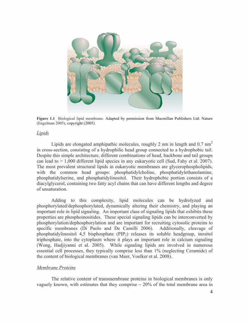
coverage of the literature, and I apologize in advance for any seminal papers that I do not cite. 1.2 Lipid Membranes in Biology The primary role of lipid bilayer membranes is compartmentalization. All cells are essentially membrane-bound compartments, enabling them to accumulate and retain the many resources necessary for life. Eukaryotic cells additionally compartmentalize internal metabolic reactions in a variety of membrane enclosed organelles. Membranes serve as the gateway across which signals are sent and received, and materials imported and exported. Biological membranes are a melting pot of different lipid molecules, sterols and membrane proteins. This variety of chemical species is necessary to support the diverse biological processes that occur in association with membranes. They also provide the substrate for a wide range of enzymatic reactions, such as lipid mediated signaling. But a purely chemical description of lipid membranes is insufficient to capture their important role in cells. Lipid membranes exhibit two-dimensional fluidity, and they have mechanical properties that govern the way they bend, fuse and break, each of which has important repercussions in fundamental processes, such as cell motility, division and intracellular trafficking. In the next few sections, I will discuss the composition of biological membranes, their organization and physical properties, and the use of synthetic lipid membranes as models for understanding properties of biological membranes. 1.2.1 Composition of Biological Membranes The main components of biological membranes are lipids, sterols, and membrane proteins. These molecules maintain close contact as a result of their amphipathic nature, forming an effective permeability barrier against diffusion of hydrophilic molecules. Early models of biological membranes suggested that they were a so-called fluid mosaic, consisting of dispersed membrane proteins floating in a uniform sea of lipids (Singer and Nicolson 1972). It is now quite clear that biological membranes are heterogeneous mixtures of lipids, with a dense population of membrane proteins (Engelman 2005) (Figure 1.1). I will briefly discuss the structure of individual lipids and membrane proteins, focusing on transmembrane proteins which span both leaflets of the bilayer, and will use a few common examples to illustrate their basic properties.
4
Figure 1.1 Biological lipid membrane. Adapted by permission from Macmillan Publishers Ltd: Nature (Engelman 2005), copyright (2005). Lipids Lipids are elongated amphipathic molecules, roughly 2 nm in length and 0.7 nm2 in cross-section, consisting of a hydrophilic head group connected to a hydrophobic tail. Despite this simple architecture, different combinations of head, backbone and tail groups can lead to > 1,000 different lipid species in any eukaryotic cell (Sud, Fahy et al. 2007). The most prevalent structural lipids in eukaryotic membranes are glycerophospholipids, with the common head groups: phosphatidylcholine, phosphatidylethanolamine, phosphatidylserine, and phosphatidylinositol. Their hydrophobic portion consists of a diacylglycerol, containing two fatty acyl chains that can have different lengths and degree of unsaturation.
Adding to this complexity, lipid molecules can be hydrolyzed and phosphorylated/dephosphorylated, dynamically altering their chemistry, and playing an important role in lipid signaling. An important class of signaling lipids that exhibits these properties are phosphoinositides. These special signaling lipids can be interconverted by phosphorylation/dephosphorylation and are important for recruiting cytosolic proteins to specific membranes (Di Paolo and De Camilli 2006). Additionally, cleavage of phosphatidylinositol 4,5 bisphosphate (PIP2) releases its soluble headgroup, inositol triphosphate, into the cytoplasm where it plays an important role in calcium signaling (Wong, Hadjiyanni et al. 2005). While signaling lipids are involved in numerous essential cell processes, they typically comprise less than 1% (neglecting Ceramide) of the content of biological membranes (van Meer, Voelker et al. 2008). Membrane Proteins The relative content of transmembrane proteins in biological membranes is only vaguely known, with estimates that they comprise ~ 20% of the total membrane area in
5
red blood cells (Dupuy and Engelman 2008). While at the time of writing more than 600 high-resolution structures of membrane proteins have been obtained, it appears that there are few general rules to describe their organization. One generalization that appears to hold true is that within these proteins, the distribution of hydrophobic residues (Ala, Ile, Val and Leu) peaks in the interior of the membrane, the distribution of aromatic residues (Tyr and Trp) peaks at the lipid-water interface, and polar residues are absent from the membrane interior (von Heijne 2006). Thus, membrane proteins universally have a hydrophobic core, which makes favorable interactions with the surrounding hydrophobic waist of the lipid bilayer, and they may have polar domains that protrude into the cytoplasmic or extracellular spaces.
In contrast to the emerging structural understanding of membrane proteins, it has long been appreciated that they play an essential role in many cellular processes. In fact, it’s estimated that 20-30% of all open reading frames in typical genomes encode for transmembrane proteins (Krogh, Larsson et al. 2001). Their many functional roles include energy production, signal transduction, directed transport and membrane fusion (Whitelegge, Gomez et al. 2003). I will briefly introduce the family of transmembrane proteins that mediate membrane fusion, which is an essential step in all intracellular trafficking events. Membrane fusion enables transport of soluble components between distinct compartments within the cell, and simultaneous deposition of lipids and proteins into the acceptor membrane. For example, exocytosis is the fusion of intracellular vesicles with the plasma membrane, and it is necessary for both deposition of membrane receptors into the plasma membrane and release of hormones and neurotransmitters during intercellular signaling (Martens and McMahon 2008).
The process of membrane fusion involves high energetic barriers, and requires the
action of proteins that destabilize lipid membranes and bring them into close apposition for fusion (Chernomordik and Kozlov 2008). The core fusion machinery for exocytosis consists of the SNARE proteins, which reside in each apposing membrane, and contain SNARE motifs that contribute to formation of a 4-helix bundle, called the SNARE complex (Martens and McMahon 2008). Formation of the SNARE complex tethers the apposing membranes and provides the energy that destabilizes the membrane and favours fusion. In the case of exocytosis in neuronal synapses, the SNARE-family proteins are synaptobrevin (resides in the synaptic vesicle), and SNAP25 and syntaxin-1 (reside in the plasma membrane). Membrane fusion of small lipid vesicles by neuronal SNARE proteins has been reconstituted in vitro (Weber, Zemelman et al. 1998), and has provided a powerful assay for characterizing the role of multiple accessory proteins, such as MUNC13, MUNC18, complexins, and synaptotagmins (Jahn and Scheller 2006). In Chapter 5, I will present an assay for reconstituting SNARE-mediated fusion in the physiologic geometry. 1.2.2 Organization of Lipid Membranes Lipid membranes can exhibit both lateral and transbilayer heterogeneity, and this is important to their function in cells. In the plane of the membrane, lipids molecules can phase separate when the entropic cost of de-mixing is overcome by the enthalpic gain of
6
lipid interactions. Depending on the structure and packing of the lipids, which is largely dependent on the degree of unsaturation of their fatty acyl tails and the presence of cholesterol, they can form liquid-disordered, liquid-ordered or solid domains (Ipsen, Karlstrom et al. 1987). This process has been studied in great detail in simplified model membranes (Veatch and Keller 2005), and their presence has been hotly debated in biological membranes, where they may play an important role in concentrating transmembrane proteins that partition into these microdomains, or lipid rafts, as the result of favorable interactions with the raft lipids (Simons and Gerl 2010). The plasma membrane of cells is asymmetrically organized, with phosphatidylserine (PS) and phosphatidylethanolamine (PE) enriched on the cytosolic leaflet, and sphingomyelin (SM) and glycosphingolipids (GSLs) enriched on the extra-cellular leaflet (van Meer, Voelker et al. 2008). In the case of SM and GSLs the lipid is synthesized on the lumenal side of the Golgi, and retains that orientation after delivery to the plasma membrane. However, for PS and PE, the small lipid head group greatly increases the rate of transbilayer exchange (Homan and Pownall 1988; Anglin and Conboy 2009), termed flip-flop, and cells must maintain the asymmetric distribution by the action of ATP-dependent aminophospholipid transporters (Daleke and Lyles 2000). Lipid asymmetry has a number of important consequences. Oligosaccharides of the extracellular facing GSLs form a thin glycocalyx which has a role in cell-cell signaling and adhesion (Weinbaum, Tarbell et al. 2007). Furthermore, transfer of PS to the external leaflet has been identified as a mechanism used by dying cells to signal phagocytic uptake by macrophages (Wu, Tibrewal et al. 2006).
Similarly, transmembrane proteins are oriented in biological membranes, enabling them to conduct their necessary function, such as transducing signals from the outside to the inside of a cell, or unidirectionally transporting ions for the generation of electrochemical gradients. Transmembrane protein orientation is accomplished during insertion of the protein into the bilayer by the translocation complex as specified by their signal sequence (Kida, Morimoto et al. 2007). 1.2.3 Physical Properties of Lipid Membranes Lipid membranes are exceedingly complex materials, and their peculiar physical properties have been the focus of physicist’s attention for over forty years. The mechanical description of lipid membranes considers their response to three types of deformations: extension, bending, and shear. In general, lipid membranes exhibit high resistance to extension, moderate resistance to bending, and no resistance to shear (recall, they’re fluid). Here I will discuss theory and measurements of these key properties. Membrane Fluidity The fluidity of lipid membranes is the result of the non-covalent interactions between lipid molecules, enabling them to move freely past each other in the plane of the membrane. This property has been studied by a number of different techniques, including Fluorescence Recovery After Photobleaching (FRAP), Fluorescence
7
Correlation Spectroscopy (FCS) and Single Particle Tracking (SPT) (Chen, Lagerholm et al. 2006). In FRAP experiments, a lipid dye is incorporated into the bilayer membrane, and irreversibly photobleached in a small region by continuous excitation. When the continuous excitation is stopped, the photobleached region recovers by diffusive mixing with neighboring regions. The diffusion constant of the lipid membrane can then be calculated from the rate of fluorescence recovery. For model lipid membranes, lipids exhibit a diffusion constant of ~ 1 – 5 µm2/s (Groves and Boxer 1995; Weng, Kanter et al. 2006). Biological membranes are characterized by diffusion constants that are approximately ten-fold lower than model membranes (Douglass and Vale 2005). Membrane Elasticity The elasticity of lipid membranes can be described by two elastic moduli. The energetic penalty for stretching apart the individual lipid molecules in the membrane, which gradually exposes the hydrophobic core of the bilayer to water, is known as the area compression modulus, KA. The energetic cost of bending the membrane, which frustrates the packing of lipid molecules similarly resulting in exposure of the hydrophobic core to water, is the bending modulus κc. These parameters define the way membranes undulate due to thermal forces, and the way they respond to being stretched. For example, the increase in membrane tension due to the relative increase in membrane area is given implicitly by the following equation,
(1.1)
where α = ΔA/A is the relative increase in membrane area, kB is Boltzmann’s constant, T is the temperature, c ~ 0.03 is a coefficient, σ is the membrane tension, and A is the area of the unstressed membrane.
Multiple techniques have been developed for measuring the elastic moduli of lipid membranes (Evans and Rawicz 1990; Dobereiner, Gompper et al. 2003). The most widely used of these techniques is Micropipet Aspiration (MPA), which uses micropipet suction to stretch the membrane of a lipid vesicle or cell, while simultaneously measuring the membrane tension. At low membrane tension (σ < 0.1 kBT/nm2), membrane area increases by “smoothing out” the thermally undulating wrinkles in the membrane. The rate of relative area increase with increasing tension can be used to calculate κc using Equation (1.1). At high membrane tension (0.1 kBT/nm2 < σ < 2.5 kBT/nm2), membrane undulations are largely suppressed, and membrane area increases as the result of increasing the spacing of the lipid molecules. In this regime, the rate of membrane area increase with tension can be used to calculate KA according to Equation (1.1). However, in the high tension regime membranes are relatively inextensible, and will typically lyse if the area / lipid is increased more than a few percent (Evans and Rawicz 1990).
MPA experiments have been used to characterize both model and biological
membranes, over a wide variety of lipid compositions. Typical values of bending modulus range from κc ~ 10 – 30 kBT for synthetic bilayers (Duwe, Kaes et al. 1990;
8
Evans and Rawicz 1990), and κc ~ 10 – 100 kBT for cellular membranes (Duwe, Kaes et al. 1990; Peterson, Strey et al. 1992). Whereas the apparent area extension modulus ranges from KA ~ 25 – 50 kBT/nm2 for synthetic bilayers (Evans and Rawicz 1990; Rawicz, Olbrich et al. 2000), it is slightly higher, KA ~ 100 kBT/nm2 for biological membranes (Evans and Waugh 1977). These two parameters are in general related by the simple relationship, κc ~ ΚΑt2, were t is the thickness of the lipid bilayer (t ~ 4 nm) (Evans and Rawicz 1990). This relationship between lipid length and membrane stiffness has been confirmed; however, it is not the entire story, and one important exception is that unsaturated lipids tend to produce more flexible membranes (lower κc) than saturated lipids (Rawicz, Olbrich et al. 2000).
A theoretical description of membrane energetics was accomplished in the 1970’s
by W. Helfrich (Helfrich 1973), and gained popularity after its success describing the shape of red blood cells (Deuling and Helfrich 1976). Given two assumptions: (1) conservation of volume, and (2) no change in surface topology, the energy of a closed membrane can be described by the following Helfrich free energy,
€
E = σ∫ dA +12
κC∫ C1 + C2 −C0( )2dA (1.2)
where C1 and C2 are the two principle curvatures, and C0 is the spontaneous curvature, which can be non-zero as a result of lipid structure and transbilayer asymmetry. Equation (1.2) provides a useful tool for calculating the energetics of membrane deformations, such as the tubular membrane protrusions of filopodia, which will be discussed in Section 1.4.2 and again in Chapter 2. 1.2.4 Model Lipid Membranes Due in large part to the complexity of biological membranes, researchers have developed numerous techniques for making model lipid membranes of controlled composition from purified or synthetic lipid molecules. Formation of lipid membranes with controlled composition has enabled insight into how the molecular properties of lipid molecules affect the physical properties of lipid membranes, such as fluidity, phase separation, bending and stretching. Model membranes come in many shapes and sizes, from planar supported lipid bilayers to spherical lipid vesicles. Supported lipid bilayers consist of a large planar bilayer membrane which float on a nanometer layer of water above a solid substrate such as glass or mica (Chan and Boxer 2007). The planar geometry of supported bilayers makes them ideal for microscopy, and micropatterning of the substrate enables engineering spatial organization on the micron lengthscale (Groves and Boxer 2002). Since the fluidity of individual lipids within supported bilayers is unperturbed by the substrate, they provide an important testbed for studying the dynamics of lipids and associated proteins, and engineering synthetic cell-cell interfaces (Mossman, Campi et al. 2005). However, the presence of the substrate prevents the use of supported bilayers for studying processes involving membrane curvature and deformation, or transbilayer signal transduction and transport.
9
Alternatively, unsupported lipid bilayers, formed vertically between two aqueous droplets, have been used to study transport across lipid bilayers by transmembrane channels (Bayley, Cronin et al. 2008), but they are difficult to image by conventional microscopy.
An alternative to planar bilayers are spherical lipid vesicles which can be made in
a variety of different sizes. Small unilamellar vesicles (SUVs) made by sonication or extrusion are < 100 nm, large unilamellar vesicles made by extrusion are 100 nm – 1 µm, and giant unilamellar vesicles (GUVs) made by gentle swelling or electroformation have diameters > 1 µm. GUVs offer a number of advantages over supported lipid membranes, including physiological membrane tension and curvature, and the ability to manipulate them to measure their physical properties. Enticingly, GUVs can also be made similar in size to individual cells, and thereby provide an ideal system for encapsulation of biological reagents for cellular reconstitution. A central challenge for engineering model membranes is to obtain greater control over their composition and organization for reconstitution experiments and engineering synthetic cell-like devices. Incorporation of transmembrane proteins with controlled orientation and control of transbilayer lipid asymmetry are two features of particular interest that will be addressed in Chapter 5. 1.3 The Actin Cytoskeleton The plasma membrane lives in constant contact with the cytoskeleton, a network of filamentous protein polymers that provide the internal infrastructure of cells, and largely define their mechanical properties. It may be stabilized by a cortical network of filaments, or it may be “pushed” by polymerization forces, or “pulled” by the molecular motors that walk along the filaments, creating a wide variety of cellular shapes. There are three major classes of cytoskeletal filaments in eukaryotic cells, actin filaments, microtubules and intermediate filaments. Here I shall focus on the actin cytoskeleton, which is found in all eukaryotic organisms and plays important roles in internal transport, endocytosis, cell motility, mechanotransduction, and division (Fletcher and Mullins 2010). The actin cytoskeleton is involved in a multiplicity of cellular activities. Actin filaments can polymerize in a cooperative fashion at the plasma membrane to generate the forces of cell motility, or invert this action to propel membrane invaginations during endocytosis. They provide internal tracks for directed transport, and can re-organize to form the cytokinetic ring which constricts to divide one cell into two. In order to understand the diverse cellular functions carried out by the actin cytoskeleton, we must also consider the roles some 100+ actin binding proteins (ABPs), which govern the spatiotemporal dynamics of actin filaments (Pollard and Cooper 1986; Pollard and Cooper 2009).
10
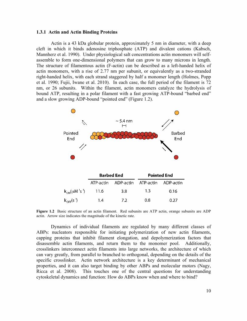
1.3.1 Actin and Actin Binding Proteins Actin is a 43 kDa globular protein, approximately 5 nm in diameter, with a deep cleft in which it binds adenosine triphosphate (ATP) and divalent cations (Kabsch, Mannherz et al. 1990). Under physiological salt concentrations actin monomers will self-assemble to form one-dimensional polymers that can grow to many microns in length. The structure of filamentous actin (F-actin) can be described as a left-handed helix of actin monomers, with a rise of 2.77 nm per subunit, or equivalently as a two-stranded right-handed helix, with each strand staggered by half a monomer length (Holmes, Popp et al. 1990; Fujii, Iwane et al. 2010). In each case, the full period of the filament is 72 nm, or 26 subunits. Within the filament, actin monomers catalyze the hydrolysis of bound ATP, resulting in a polar filament with a fast growing ATP-bound “barbed end” and a slow growing ADP-bound “pointed end” (Figure 1.2).
Figure 1.2 Basic structure of an actin filament. Red subunits are ATP actin, orange subunits are ADP actin. Arrow size indicates the magnitude of the kinetic rate. Dynamics of individual filaments are regulated by many different classes of ABPs: nucleators responsible for initiating polymerization of new actin filaments, capping proteins that inhibit filament elongation, and depolymerization factors that disassemble actin filaments, and return them to the monomer pool. Additionally, crosslinkers interconnect actin filaments into large networks, the architecture of which can vary greatly, from parallel to branched to orthogonal, depending on the details of the specific crosslinker. Actin network architecture is a key determinant of mechanical properties, and it can also target binding by other ABPs and molecular motors (Nagy, Ricca et al. 2008). This touches one of the central questions for understanding cytoskeletal dynamics and function: How do ABPs know when and where to bind?
11
1.3.2 Mechanics of Actin Filaments
Actin filaments are a major structural component of cells, generating the forces for numerous processes and providing much of their mechanical integrity. I will briefly discuss the ability of actin polymerization to generate force, the stiffness of actin filaments, and filaments’ ability to sustain external loads.
Growth of actin filaments occurs when the rate of monomer addition exceeds the rate of deletion. This can be described in terms of the equilibrium constant of the equation, Keq = kON / kOFF, or equivalently by the critical concentration, Kc = 1 / Keq = kOFF / kON. When [A], the concentration of free actin monomers, is great than Kc actin filaments will elongate, and when [A] is less than Kc they will shrink. External force affects the equilibrium constant according to Boltzmann’s Equation, yielding
€
KeqF = Keqe
(−Fδ / kBT ), where is the equilibrium constant under force, F is the load force and δ is the increase in filament length upon monomer addition (δ ~ 2.7 nm). Thus, monomer addition and deletion are precisely balanced at the stall force,
(1.3)
The stall force represents the largest force that can be generated by polymerization, and is on the order of 8 pN in cells with [A] ~ 30 µM (Howard 2001). Polymerization stall forces up to ~ 1 pN have been observed in vitro (Footer, Kerssemakers et al. 2007). This force is less than the force required to generate large deformations in lipid membranes, necessitating the coordinated effort of multiple actin filaments for cellular shape change, as we will see in the case of filopodial protrusions (Section 1.4.2).
To treat the mechanical rigidity of actin filaments, we make the simplifying assumption that actin filaments are thin (uniform) rods. We can simply define their flexural rigidity, κf, as the product of the Young’s modulus, Y, and the moment of inertia of the cross-section, I (i.e. κf = YI). More common is to discuss the persistence length, Lp = κf / kBT, which is the length scale over which the orientation of the filament becomes uncorrelated due to thermal fluctuations. It follows from this description that the energy associated with bending fluctuations is given by,
(1.4)
known as the Kratky-Porod model, where β = 1 / kBT, κ is the local curvature of the filament, and the integral runs the entire length of the filament (Boal 2002). The remarkable fact that actin monomers can form filaments many microns in length enabled calculation of their persistence length by direct observation of their thermal fluctuations. Free actin filaments have a persistence length, Lp ~ 9 µm (Isambert, Venier et al. 1995).
The ability of actin filaments to resist deforming under load is crucial to their function in cells. It was demonstrated in the 18th century by Leonhard Euler that beyond a certain compressive force, a slim rod will becomes unstable to any lateral deformation.
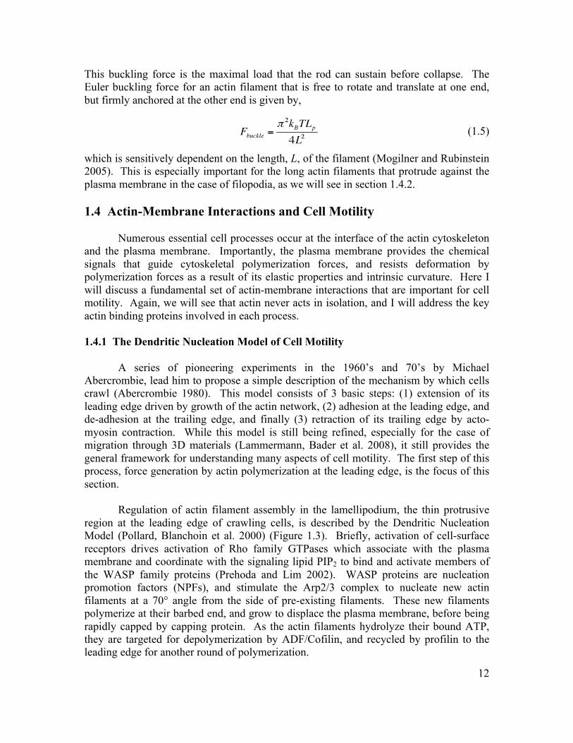
12
This buckling force is the maximal load that the rod can sustain before collapse. The Euler buckling force for an actin filament that is free to rotate and translate at one end, but firmly anchored at the other end is given by,
(1.5)
which is sensitively dependent on the length, L, of the filament (Mogilner and Rubinstein 2005). This is especially important for the long actin filaments that protrude against the plasma membrane in the case of filopodia, as we will see in section 1.4.2. 1.4 Actin-Membrane Interactions and Cell Motility Numerous essential cell processes occur at the interface of the actin cytoskeleton and the plasma membrane. Importantly, the plasma membrane provides the chemical signals that guide cytoskeletal polymerization forces, and resists deformation by polymerization forces as a result of its elastic properties and intrinsic curvature. Here I will discuss a fundamental set of actin-membrane interactions that are important for cell motility. Again, we will see that actin never acts in isolation, and I will address the key actin binding proteins involved in each process. 1.4.1 The Dendritic Nucleation Model of Cell Motility A series of pioneering experiments in the 1960’s and 70’s by Michael Abercrombie, lead him to propose a simple description of the mechanism by which cells crawl (Abercrombie 1980). This model consists of 3 basic steps: (1) extension of its leading edge driven by growth of the actin network, (2) adhesion at the leading edge, and de-adhesion at the trailing edge, and finally (3) retraction of its trailing edge by acto-myosin contraction. While this model is still being refined, especially for the case of migration through 3D materials (Lammermann, Bader et al. 2008), it still provides the general framework for understanding many aspects of cell motility. The first step of this process, force generation by actin polymerization at the leading edge, is the focus of this section.
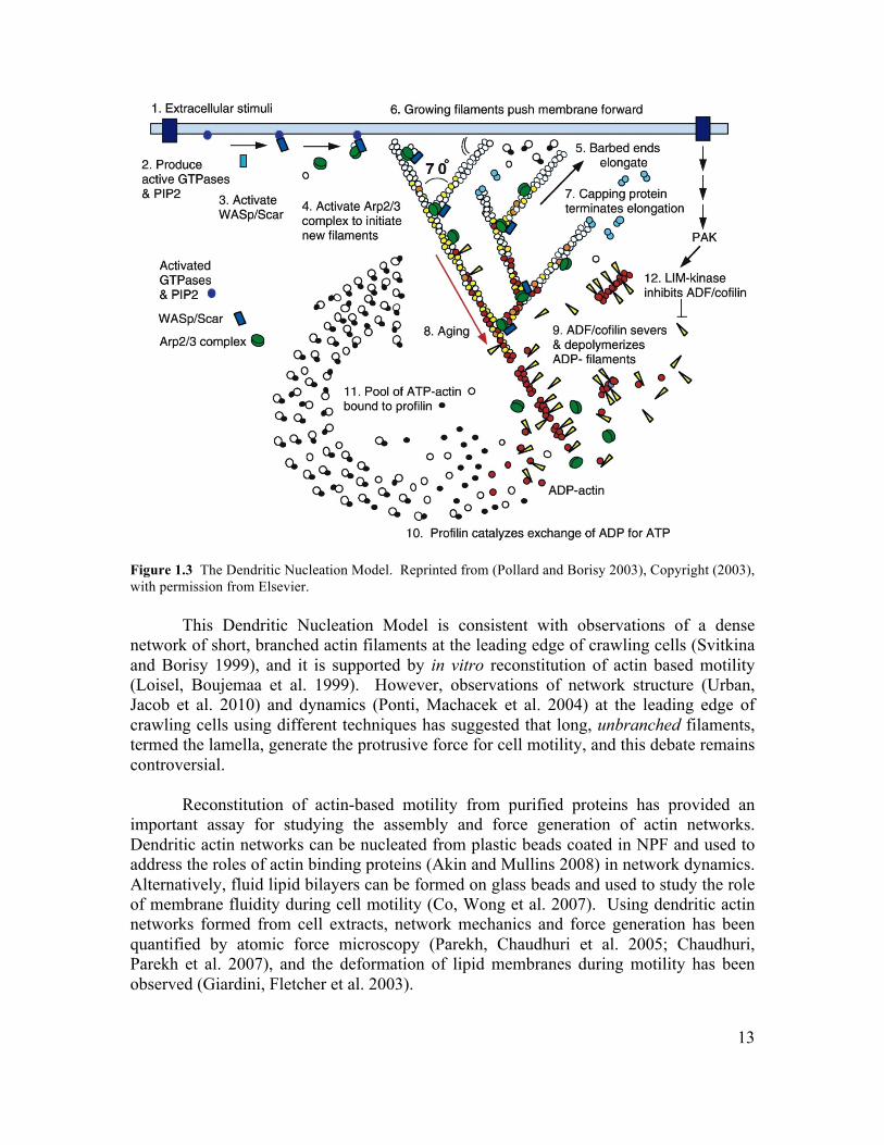
Regulation of actin filament assembly in the lamellipodium, the thin protrusive region at the leading edge of crawling cells, is described by the Dendritic Nucleation Model (Pollard, Blanchoin et al. 2000) (Figure 1.3). Briefly, activation of cell-surface receptors drives activation of Rho family GTPases which associate with the plasma membrane and coordinate with the signaling lipid PIP2 to bind and activate members of the WASP family proteins (Prehoda and Lim 2002). WASP proteins are nucleation promotion factors (NPFs), and stimulate the Arp2/3 complex to nucleate new actin filaments at a 70° angle from the side of pre-existing filaments. These new filaments polymerize at their barbed end, and grow to displace the plasma membrane, before being rapidly capped by capping protein. As the actin filaments hydrolyze their bound ATP, they are targeted for depolymerization by ADF/Cofilin, and recycled by profilin to the leading edge for another round of polymerization.
13
Figure 1.3 The Dendritic Nucleation Model. Reprinted from (Pollard and Borisy 2003), Copyright (2003), with permission from Elsevier.
This Dendritic Nucleation Model is consistent with observations of a dense network of short, branched actin filaments at the leading edge of crawling cells (Svitkina and Borisy 1999), and it is supported by in vitro reconstitution of actin based motility (Loisel, Boujemaa et al. 1999). However, observations of network structure (Urban, Jacob et al. 2010) and dynamics (Ponti, Machacek et al. 2004) at the leading edge of crawling cells using different techniques has suggested that long, unbranched filaments, termed the lamella, generate the protrusive force for cell motility, and this debate remains controversial. Reconstitution of actin-based motility from purified proteins has provided an important assay for studying the assembly and force generation of actin networks. Dendritic actin networks can be nucleated from plastic beads coated in NPF and used to address the roles of actin binding proteins (Akin and Mullins 2008) in network dynamics. Alternatively, fluid lipid bilayers can be formed on glass beads and used to study the role of membrane fluidity during cell motility (Co, Wong et al. 2007). Using dendritic actin networks formed from cell extracts, network mechanics and force generation has been quantified by atomic force microscopy (Parekh, Chaudhuri et al. 2005; Chaudhuri, Parekh et al. 2007), and the deformation of lipid membranes during motility has been observed (Giardini, Fletcher et al. 2003).
14
1.4.2 The Convergent Elongation Model of Filopodia Formation
One of the most striking examples of membrane deformations by actin polymerization is the formation of thin finger-like protrusions, termed filopodia, from the leading edge of crawling cells (Faix and Rottner 2006). Filopodia play a diverse set of functional roles in single cell motility, collective cell motility, cell-cell signaling and tissue development, and they are consequently defined in terms of their stereotypical architecture. Filopodia consist of a parallel, polar array of 20-50 actin filaments ensheathed by a membrane tube, roughly 100nm in diameter.
The structure of filopodia can be largely understood in terms of the forces
involved. A point force directed perpendicular to a planar membrane will result, beyond a threshold force, in formation of a membrane tube. This has been demonstrated theoretically (Derenyi, Julicher et al. 2002), and confirmed experimentally (Raucher and Sheetz 1999; Koster, Cacciuto et al. 2005). Using Equation (1.1), it is easy to calculate the energetics of a membrane tube, and the resulting force of extension. Neglecting the membrane cap at the tip and assuming a membrane with zero spontaneous curvature, the entire tube is characterized by a constant mean curvature,
€
H = 12 (C1 + C2 −C0) = 12Rwhere R is the radius of the tube. Integrating over the surface of the cylindrical tube
yields , where κc is the membrane bending rigidity, σ is the
membrane tension, and L is the length of the tube. Minimizing the energy with respect to
the radius yields . The radius of the membrane tube is determined by a balance between the membrane tension, which favors a smaller radius and less membrane area, and the bending rigidity which favors a larger radius and lower curvature. Typical values of membrane tension and bending rigidity, σ ~ 0.005 kBT/nm2 and κc ~ 30 kBT (see Section 1.2.3), result in a tube radius of R ~ 50nm, consistent with what is observed in cells (Urban, Jacob et al. 2010). The force required to maintain a membrane tube at constant length can be calculated by differentiating the energy with respect to length at constant radius, , yielding a load force of F ~ 12 pN for membrane parameters as above. Experiments which pull membrane tethers from cells yield slightly higher force values, F = 10 – 50 pN, likely due to the additional energetic penalty of breaking membrane-cortex links during this process (Shao and Hochmuth 1996). Based on similar arguments, it was deduced that a minimum of ~ 10 actin filaments are required to generate the protrusive force to form a filopodium, which underscores the need for cooperativity of actin filaments during this process (Mogilner and Rubinstein 2005).
The precise mechanism by which actin filaments coordinate protrusion to form
filopodia remains an important and controversial question in the field of cell motility (Faix, Breitsprecher et al. 2009). Filopodia appear to arise from the underlying dendritic network, and this observation is at the heart of the Convergent Elongation Model (Figure 1.4), which describes the formation of filopodia as an architectural transition from branched to bundled actin filaments (Svitkina, Bulanova et al. 2003; Mejillano, Kojima et al. 2004). The Convergent Elongation Model proposes that a number of actin filaments
15
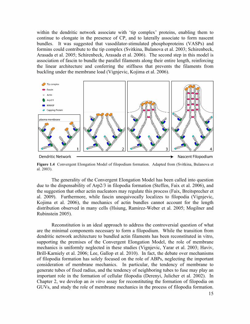
within the dendritic network associate with ‘tip complex’ proteins, enabling them to continue to elongate in the presence of CP, and to laterally associate to form nascent bundles. It was suggested that vasodilator-stimulated phosphoproteins (VASPs) and formins could contribute to the tip complex (Svitkina, Bulanova et al. 2003; Schirenbeck, Arasada et al. 2005; Schirenbeck, Arasada et al. 2006). The second step in this model is association of fascin to bundle the parallel filaments along their entire length, reinforcing the linear architecture and conferring the stiffness that prevents the filaments from buckling under the membrane load (Vignjevic, Kojima et al. 2006).
Figure 1.4 Convergent Elongation Model of filopodium formation. Adapted from (Svitkina, Bulanova et al. 2003).
The generality of the Convergent Elongation Model has been called into question
due to the dispensability of Arp2/3 in filopodia formation (Steffen, Faix et al. 2006), and the suggestion that other actin nucleators may regulate this process (Faix, Breitsprecher et al. 2009). Furthermore, while fascin unequivocally localizes to filopodia (Vignjevic, Kojima et al. 2006), the mechanics of actin bundles cannot account for the length distribution observed in many cells (Hsiung, Ramirez-Weber et al. 2005; Mogilner and Rubinstein 2005).
Reconstitution is an ideal approach to address the controversial question of what
are the minimal components necessary to form a filopodium. While the transition from dendritic network architecture to bundled actin filaments has been reconstituted in vitro, supporting the premises of the Convergent Elongation Model, the role of membrane mechanics is uniformly neglected in these studies (Vignjevic, Yarar et al. 2003; Haviv, Brill-Karniely et al. 2006; Lee, Gallop et al. 2010). In fact, the debate over mechanisms of filopodia formation has solely focused on the role of ABPs, neglecting the important consideration of membrane mechanics. In particular, the tendency of membrane to generate tubes of fixed radius, and the tendency of neighboring tubes to fuse may play an important role in the formation of cellular filopodia (Derenyi, Julicher et al. 2002). In Chapter 2, we develop an in vitro assay for reconstituting the formation of filopodia on GUVs, and study the role of membrane mechanics in the process of filopodia formation.
16
We demonstrate that filopodium formation can occur in the absence of tip complex and bundling proteins, and that Euler buckling under the membrane load does not govern filopodium stability. 1.5 Cellular Reconstitution The cellular organization of biological organisms was first observed in 1665 by Robert Hooke, and continues to provide the basic framework for describing living systems. Cells have an impressive repertoire of different activities, and outdo the most complicated man-made devices for their complexity, adaptability and plasticity. Surprisingly, even fragments of cells are often capable of running complex cellular programs and executing behaviour that is indecipherable from that of their living counterparts. For example, cytoplasts are cell fragments lacking nuclei and organelles that exhibit persistent directed motility (Verkhovsky, Svitkina et al. 1999). This observation illustrates an important design feature of biological systems - they appear to run on ‘molecular autopilot’. Indeed, many biological processes can successfully be described using the concepts of directed self-assembly, in which component parts self-assemble into larger functional structures in response to internal or external cues. Reconstitution provides a powerful approach for exploring the principle of self-assembly in biology (Liu and Fletcher 2009). The primary goal of reconstitution experiments is to recapitulate a complex cellular function from the minimal set of components and requisite boundary conditions. For example, cell motility, which is a cell-scale activity and could in principle require a huge number of accessory proteins, has been minimally reconstituted using a set of only five different proteins (Loisel, Boujemaa et al. 1999). Importantly, this establishes a simple model for the process of cell motility which can be intuitively understood, and upon which layers of complexity can be added. By further adding or subtracting non-essential ABPs, or simply titrating protein concentration, we can alter the global behaviour of the system. Thus, reconstitution allows us to distill out the essential aspects of motility, and then build up the complexity in an understandable way. This provides an essential tool for gaining insight and intuition into the way that self-assembling systems work, and for exploring the emergent properties that arise. From an engineering perspective, directed self-assembly is an intriguing design principle, and is remarkably different from conventional engineering approaches. For example, the challenge of reconstitution is often to specify the correct set of components, their stoichiometric ratios, and the requisite boundary conditions that direct the self-assembly process. We don’t assemble actin comet tails by carefully securing each monomer in its final place, rather we mix together the active ingredients under conditions which result in actin polymerization at the active surface. As a result, no two self-assembled actin networks are the same, and likewise no two cells are identical. An important lesson from this work is that the boundary conditions often govern the behaviour of the system, and offer the primary level of control.
17
The boundary conditions of cells are largely specified by their bounding plasma membrane. Indeed, compartmentalization is a fundamental feature of cells, and as such, it is intrinsically linked to many cellular activities, such as signal transduction, shape change, motility and division. Furthermore, there are important physical consequences of confining biochemical reactions on the length scale of cells, that aren’t captured by bulk in vitro assays. Thus, encapsulation of bioactive materials in cell-like containers is an essential step for reconstitution of complex cellular behavior. Furthermore, encapsulation will provide a means to harness the power of bioactive materials for cell-like devices that aim to accomplish complex tasks like tracking down and engulfing bacteria in the body. Here I will discuss the physical consequences of confining bioactive materials and recent techniques that achieve confinement in various cell-sized containers for reconstitution. I will then consider the promise and possibility of building cell-like devices from bioactive materials. Finally, I will consider some future challenges of this approach to understanding cell biology. 1.5.1 Encapsulation for Cellular Reconstitution
Compartmentalization is thought to be one of the earliest features of living systems (Schrum, Zhu et al. 2010), enabling cells to distinguish themselves from their environment, and thereby accumulate the materials necessary for life and retain genetic variations that confer a competitive advantage. As a result, cells have evolved numerous activities which are intrinsically linked to their global organization: machinery to propel themselves forward in order explore their external environment, mechanisms to interact by transducing chemical and mechanical signals across their plasma membrane, and internal infrastructure to separate genetic material during cell division. But compartmentalization also has important consequences for the reactions that underpin these larger processes. Confinement of biochemical reactions on the length scale of cells can shift their outcomes and make new behaviors possible, with important consequences for the internal organization of cells.
Dynamic organization of a cell’s internal compartments is largely accomplished
by microtubules – another class of cytoskeletal polymers that generate force by polymerization/depolymerization, and provide tracks for intracellular trafficking by molecular motors. For example, the model organism S. pombe (fission yeast) uses a network of microtubules emanating from the microtubule organizing center to maintain the central position of its nucleus during interphase. These microtubules span the distance between the nucleus and the cell tips, and generate balanced pushing forces that center the nucleus (Tran, Marsh et al. 2001), and can re-center a displaced nucleus (Tolic-Norrelykke, Sacconi et al. 2005; Daga, Yonetani et al. 2006). Similarly during mitosis, polymerizing microtubules interact with the cell boundary to center the future spindle, and maintain the alignment of the spindle with the cell axis, ensuring that each daughter cell inherits a full copy of genetic material (Tolic-Norrelykke, Sacconi et al. 2004; Vogel, Raabe et al. 2007). Interestingly, it has been shown that the organization of microtubules radiating from a microtubule organizing center (Pinot, Chesnel et al. 2009), and the alignment (Minc, Burgess et al. 2011) and physical size of the mitotic spindle (Dumont
18
and Mitchison 2009), are all sensitively dependent on the size and geometry of the container.
For efficient centering by pushing, microtubules must be highly dynamic, with
enhanced depolymerization events (catastrophes) at the cell periphery (Faivre-Moskalenko and Dogterom 2002). Mathematical modeling demonstrates that confinement may influence the dynamics of microtubules in cells, and can even account for the observed length distribution without the need to assume the activity of microtubule associating proteins (Gregoretti, Margolin et al. 2006). There are also numerous examples of microtubules positioning internal structures using pulling forces, provided by depolymerization or associated motor proteins. Interestingly, it has been suggested that the mechanism cells use depends on their size and geometry, with pushing forces most prevalent in small, symmetric cells, and pulling forces more common in larger asymmetric cell types (Tolic-Norrelykke 2008).
The size of cells clearly has a number of important consequences, and it has been
suggested that viable cells must be between 0.2 – 10 µm in diameter (Noireaux, Maeda et al. 2011). The minimum size for living cells has been accounted for as the volume that can accommodate the minimum genome and protein machinery for replication and other essential metabolic activities (Knoll 1999). A useful concept to understand the upper limit is the ratio of surface area to volume, which scales as the inverse radius for a spherical cell. A primary concern is that above some critical size, the surface area to volume ratio of the cell becomes insufficient for transport to supply nutrients to sustain the internal processes and expel their accumulating waste.
The surface area to volume ratio also accounts for more subtle effects of
confinement on the dynamics of cell activity. For instance, numerous cellular reactions involved in cell signaling and motility occur between cytoplasmic molecules that independently associate with the inner surface of the plasma membrane. This has the consequence of constraining them a reduced volume, thereby increasing their effective concentrations, and resulting in an effective dissociation constant for the reaction that scales with the surface area to volume ratio (Kholodenko, Hoek et al. 2000). This provides a potential mechanism for initiating or amplifying essential biochemical reactions. Another consequence of protein binding to lipid membranes is that in systems with very high surface area to volume ratio, moderate binding affinity may lead to depletion of the reacting molecules from the cytoplasm. Again, this has important consequences for cell behaviour, and may facilitate cell polarization by suppressing growth of secondary foci (Otsuji, Ishihara et al. 2007; Altschuler, Angenent et al. 2008; Howell, Savage et al. 2009).
Recapitulating the compartmentalization and confinement of cells is an important
goal for in vitro reconstitution. However, we are faced with an inconvenient fact - compartmentalization is so fundamental to the existence of cells, that there is no machinery for accomplishing this task. Cells inherit this organizational scheme along with their genetic material and their first copy of protein machinery and organelles from their predecessors, and pass it on through successive rounds of cell division. Thus, unlike
19
DNA replication and protein expression, there is no analogous encapsulation machinery to hi-jack for the purpose of assembling cell-like systems for reconstituting cellular behaviour and engineering cell-live devices. Consequently, researchers have used engineering approaches of microfabrication and microfluidics to replicate the confined environment of cells.
Solid chambers with micron scale features can be made from glass using standard
microfabrication techniques. Microtubule asters confined in cell-sized microfabricated chambers spontaneously center, and provide an important assay for testing the relative contributions of microtubule buckling (Holy, Dogterom et al. 1997) and catastrophe (Faivre-Moskalenko and Dogterom 2002) in this self-organizing process. Additionally, the inner surface of these chambers can be functionalized by covalent attachment of motor proteins, in order to study the effect of cortical interactions and pulling forces in organization of the microtubule cytoskeleton (Romet-Lemonne, VanDuijn et al. 2005). While these chambers are ideal for studying the physical effects of confinement geometry on the organization of stiff polymers (Garner, Campbell et al. 2007; Minc, Burgess et al. 2011), they fail to replicate numerous features of the plasma membrane that are important for motility, division and signal transduction, and they preclude the possibility of forming devices.
An alternative approach for generating cell-sized containers is to form picoliter
volumes of aqueous solvent within a continuous oil phase by microfluidics (Hosokawa, Fujii et al. 1999; Atencia and Beebe 2005; Teh, Lin et al. 2008). These droplets can be stabilized by detergents or lipid molecules, which self-assemble at the oil-water interface forming inverted emulsions, importantly preventing non-specific adsorption of macromolecules, and making them useful for conducting high throughput biochemical reactions (Williams, Peisajovich et al. 2006). Inverted emulsions have also been used to study the organization of protein polymers confined to cellular length scales (Claessens, Tharmann et al. 2006); however, similar to microfabricated chambers, inverted emulsions fail to mimic the physiological properties of cellular membranes and cannot be used to engineer stable cell-like devices. Formation of water-oil-water emulsions (Takeuchi, Garstecki et al. 2005; Utada, Lorenceau et al. 2005) partially addresses this issue, but still present unphysiologically high bending rigidity, and cannot be used to study transmembrane signal transduction or transport.
The ideal containers for mimicking the biophysical boundary conditions of cells
are synthetic lipid vesicles, which can be made with complex lipid chemistry, and provide a molecularly thin, fluid deformable barrier comparable to cellular membranes. Lipid vesicles can be made over a wide range of sizes (0.02 – 10’s µm) by a variety of techniques; however, macromolecules do not spontaneously partition into the lumen of lipid vesicles during their formation. Encapsulation efficiency is typically very low for macromolecules and depends sensitively on the properties of the molecule such as size and charge. Alternatively, intended contents can be introduced after formation of giant vesicles by electroporation of the GUV membrane, or injection techniques such as electroinjection (Karlsson, Nolkrantz et al. 2000; Jesorka, Markstrom et al. 2005). Collectively, these techniques have enabled the study of GUV deformation by
20
encapsulated polymers which function in cell division (Osawa, Anderson et al. 2008) and motility (Honda, Takiguchi et al. 1999; Miyata, Nishiyama et al. 1999); however, their numerous limitations have motivated development of methods designed explicitly for controlled encapsulation in cell-sized GUVs.
Controlled encapsulation in lipid vesicles has been accomplished by centrifuging
inverted emulsions through an oil-water interface (Pautot, Frisken et al. 2003), and has been used to reconstitute protein expression (Noireaux and Libchaber 2004), and assembly of an actin cortex in GUVs (Pontani, van der Gucht et al. 2009). However, this technique offers limited control of vesicle size and suffers from low throughput (Pautot, Frisken et al. 2003). A central aim of my dissertation work was contributing to the development of a technique for forming monodisperse giant vesicles with controlled internal contents, and progress towards this aim will be discussed in Chapters 3 and 4. The ability to form lipid vesicles with controlled contents opens many possibilities for reconstituting cell signaling pathways and engineering cell-like devices. One important challenge that remains is the ability to incorporate transmembrane proteins with controlled orientation into the membranes of these vesicles, which will enable reconstitution studies of signaling and transport, and will be crucial for engineering devices that interact with their environment. I will discuss progress towards this aim in Chapter 5.
1.5.2 Engineering Cell-like Devices Many biological molecules are more complex than what can be currently designed de novo. But the continued isolation and characterization of these components offers the possibility of integrating them into biologically inspired devices with novel functionality tailored for specific applications in health and industry. It is now conceivable that a cellular device, composed of the machinery and design principles gleaned from many different organisms, could be created from the ground up. Reconstitution will help bridge the gap from basic science to innovation by providing indispensible tools and insight into the emergent properties of complex self-organizing systems. An example of this is the reconstitution of DNA polymerization by Roger Kornberg in the 1950’s (Kornberg 1960), which has increasing applications in biotechnology (He 2008). There are a number of new fields that aim to engineer functional tissues and organs from living cells and other biological materials, and even to re-engineer cells for entirely new purposes, such as bio-fuel production. There has also been considerable progress in designing synthetic devices from molecular parts for therapeutic purposes. Drug delivery particles that incorporate the drug payload into lipid micelles, biodegradable polymers, and aptameric molecules, have been developed to improve lifetime and targeting of drugs (Goldberg, Langer et al. 2007). Encapsulation of cargo, including protein enzymes, cytokines, genes, image contrast agents and small molecule drugs, into small lipid vesicles has also been accomplished (Torchilin 2005). Here I will discuss the promise and challenges of pushing beyond simple drug delivery particles, and attempting to engineer cell-inspired devices with advanced functionality (Figure 1.5).
21
Figure 1.5 Design of a cell-inspired devices. Protein expression machinery is encapsulated within a unilamellar lipid vesicle with controlled membrane properties. Incorporation of transmembrane proteins into the bilayer membrane enables signal transduction. In this case, an external stimulus triggers expression of a protein polymer that drives changes in vesicle morphology. Deformation of lipid vesicles by an encapsulated cytoskeletal network could be used to increase their retention at tumour sites, and ultimately rupture the vesicle membrane for controlled release of drug cargo.
An important advantage of building cell-like devices from basic parts is that we
avoid the potential of crosstalk and compensatory mechanisms that plague efforts to re-engineer living cells. A rather more interesting advantage of building synthetic devices from scratch is that it is easy to incorporate non-biological materials, and to take non-physiological shortcuts in the design process. Some examples that have already been explored include the use of block copolymers to form bilayer membranes (Pautot, Frisken et al. 2003), and the use of high affinity linkages such as biotin-streptavidin and His-NTANi (Nye and Groves 2008) to localize signaling molecules. This will be especially important when the goal is to deliver imaging contrast agents or drugs, which may have complicated solubility requirement or toxic effects on living cells. The freedom to use non-physiological mechanisms in our design will be important to simplify early devices, but it will also have the positive effect of empowering the user to explore novel ways to achieve functionality. Our improving physical understanding of biological mechanisms from in vitro reconstitution experiments will facilitate attempts to engineer complex behaviour from minimal components (Stachowiak, Hayden et al. 2010). In Chapter 6, I will consider the promise and challenges of engineering cell-like devices, and discuss some of our early progress towards this goal.
22
1.6 Scope of Thesis
In this dissertation, I will describe the bulk of my work as a graduate student. In Chapter 2, I will describe our reconstitution of membrane-bound, finger-like projections of the actin cytoskeleton, termed filopodia, which are important for cell-cell signaling and motility. In Chapters 3 and 4, I will introduce a new tool for encapsulating biological reagents in monodisperse lipid membrane compartments for cellular reconstitution, and in Chapter 5, I will present our work to control membrane properties of these cell-like systems. I will conclude by discussing the implications of these results in Chapter 6, and considering the benefits and challenges of cellular reconstitution and future possibilities for engineering cell-like devices. While the challenges of cellular reconstitution are considerable, the potential for fundamental insight and the promise for medical and biomaterials applications are enormous.
23
Chapter 2: Membrane-Induced Bundling of Actin Filaments
Reproduced by permission of Nature Publishing Group. Allen P. Liu*, David L. Richmond*, Lutz Maibaum, Sander Pronk, Phillip L. Geissler,
and Daniel A. Fletcher (2008). “Membrane-induced bundling of actin filaments.” Nature Physics 4(10): 789-793. *Equal contribution.
© 2008 by Nature Publishing Group
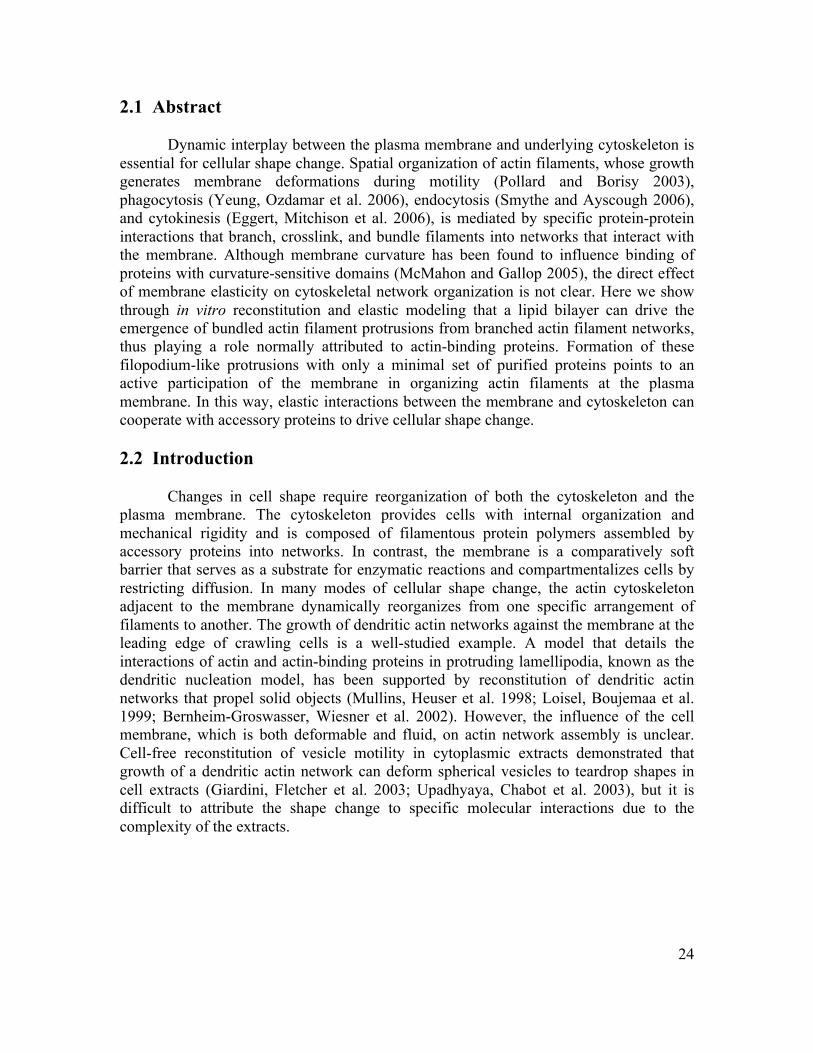
24
2.1 Abstract
Dynamic interplay between the plasma membrane and underlying cytoskeleton is essential for cellular shape change. Spatial organization of actin filaments, whose growth generates membrane deformations during motility (Pollard and Borisy 2003), phagocytosis (Yeung, Ozdamar et al. 2006), endocytosis (Smythe and Ayscough 2006), and cytokinesis (Eggert, Mitchison et al. 2006), is mediated by specific protein-protein interactions that branch, crosslink, and bundle filaments into networks that interact with the membrane. Although membrane curvature has been found to influence binding of proteins with curvature-sensitive domains (McMahon and Gallop 2005), the direct effect of membrane elasticity on cytoskeletal network organization is not clear. Here we show through in vitro reconstitution and elastic modeling that a lipid bilayer can drive the emergence of bundled actin filament protrusions from branched actin filament networks, thus playing a role normally attributed to actin-binding proteins. Formation of these filopodium-like protrusions with only a minimal set of purified proteins points to an active participation of the membrane in organizing actin filaments at the plasma membrane. In this way, elastic interactions between the membrane and cytoskeleton can cooperate with accessory proteins to drive cellular shape change. 2.2 Introduction
Changes in cell shape require reorganization of both the cytoskeleton and the
plasma membrane. The cytoskeleton provides cells with internal organization and mechanical rigidity and is composed of filamentous protein polymers assembled by accessory proteins into networks. In contrast, the membrane is a comparatively soft barrier that serves as a substrate for enzymatic reactions and compartmentalizes cells by restricting diffusion. In many modes of cellular shape change, the actin cytoskeleton adjacent to the membrane dynamically reorganizes from one specific arrangement of filaments to another. The growth of dendritic actin networks against the membrane at the leading edge of crawling cells is a well-studied example. A model that details the interactions of actin and actin-binding proteins in protruding lamellipodia, known as the dendritic nucleation model, has been supported by reconstitution of dendritic actin networks that propel solid objects (Mullins, Heuser et al. 1998; Loisel, Boujemaa et al. 1999; Bernheim-Groswasser, Wiesner et al. 2002). However, the influence of the cell membrane, which is both deformable and fluid, on actin network assembly is unclear. Cell-free reconstitution of vesicle motility in cytoplasmic extracts demonstrated that growth of a dendritic actin network can deform spherical vesicles to teardrop shapes in cell extracts (Giardini, Fletcher et al. 2003; Upadhyaya, Chabot et al. 2003), but it is difficult to attribute the shape change to specific molecular interactions due to the complexity of the extracts.
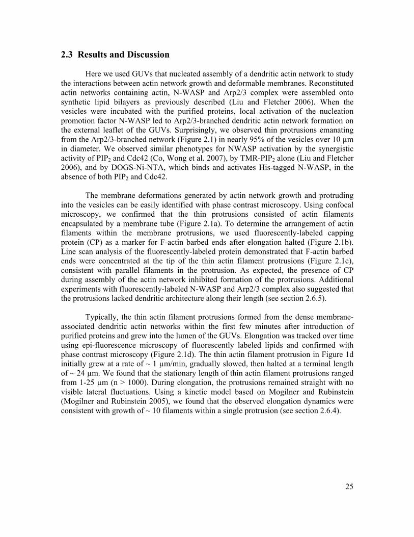
25
2.3 Results and Discussion
Here we used GUVs that nucleated assembly of a dendritic actin network to study the interactions between actin network growth and deformable membranes. Reconstituted actin networks containing actin, N-WASP and Arp2/3 complex were assembled onto synthetic lipid bilayers as previously described (Liu and Fletcher 2006). When the vesicles were incubated with the purified proteins, local activation of the nucleation promotion factor N-WASP led to Arp2/3-branched dendritic actin network formation on the external leaflet of the GUVs. Surprisingly, we observed thin protrusions emanating from the Arp2/3-branched network (Figure 2.1) in nearly 95% of the vesicles over 10 µm in diameter. We observed similar phenotypes for NWASP activation by the synergistic activity of PIP2 and Cdc42 (Co, Wong et al. 2007), by TMR-PIP2 alone (Liu and Fletcher 2006), and by DOGS-Ni-NTA, which binds and activates His-tagged N-WASP, in the absence of both PIP2 and Cdc42.
The membrane deformations generated by actin network growth and protruding
into the vesicles can be easily identified with phase contrast microscopy. Using confocal microscopy, we confirmed that the thin protrusions consisted of actin filaments encapsulated by a membrane tube (Figure 2.1a). To determine the arrangement of actin filaments within the membrane protrusions, we used fluorescently-labeled capping protein (CP) as a marker for F-actin barbed ends after elongation halted (Figure 2.1b). Line scan analysis of the fluorescently-labeled protein demonstrated that F-actin barbed ends were concentrated at the tip of the thin actin filament protrusions (Figure 2.1c), consistent with parallel filaments in the protrusion. As expected, the presence of CP during assembly of the actin network inhibited formation of the protrusions. Additional experiments with fluorescently-labeled N-WASP and Arp2/3 complex also suggested that the protrusions lacked dendritic architecture along their length (see section 2.6.5).
Typically, the thin actin filament protrusions formed from the dense membrane-associated dendritic actin networks within the first few minutes after introduction of purified proteins and grew into the lumen of the GUVs. Elongation was tracked over time using epi-fluorescence microscopy of fluorescently labeled lipids and confirmed with phase contrast microscopy (Figure 2.1d). The thin actin filament protrusion in Figure 1d initially grew at a rate of ~ 1 µm/min, gradually slowed, then halted at a terminal length of ~ 24 µm. We found that the stationary length of thin actin filament protrusions ranged from 1-25 µm (n > 1000). During elongation, the protrusions remained straight with no visible lateral fluctuations. Using a kinetic model based on Mogilner and Rubinstein (Mogilner and Rubinstein 2005), we found that the observed elongation dynamics were consistent with growth of ~ 10 filaments within a single protrusion (see section 2.6.4).
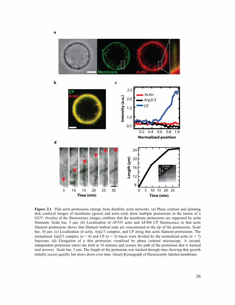
26
Figure 2.1 Thin actin protrusions emerge from dendritic actin networks. (a) Phase contrast and spinning disk confocal images of membrane (green) and actin (red) show multiple protrusions in the lumen of a GUV. Overlay of the fluorescence images confirms that the membrane protrusions are supported by actin filaments. Scale bar, 5 µm. (b) Localization of AF555 actin and AF488 CP fluorescence in thin actin filament protrusions shows that filament barbed ends are concentrated at the tip of the protrusions. Scale bar, 10 µm. (c) Localization of actin, Arp2/3 complex, and CP along thin actin filament protrusions. The normalized Arp2/3 complex (n = 4) and CP (n = 3) traces were divided by the normalized actin (n = 7) linescans. (d) Elongation of a thin protrusion visualized by phase contrast microscopy. A second, independent protrusion enters the field at 10 minutes and crosses the path of the protrusion that is tracked (red arrows). Scale bar, 3 µm. The length of the protrusion was tracked through time showing that growth initially occurs quickly but slows down over time. (Inset) Kymograph of fluorescently labeled membrane.
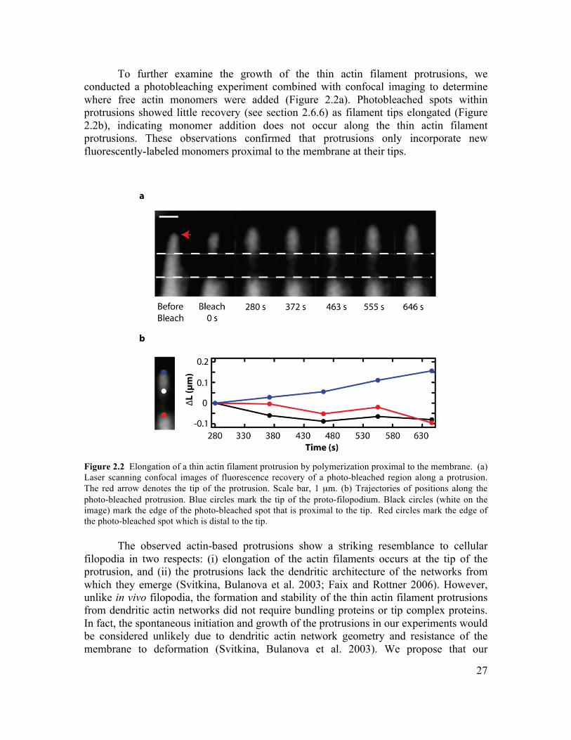
27
To further examine the growth of the thin actin filament protrusions, we conducted a photobleaching experiment combined with confocal imaging to determine where free actin monomers were added (Figure 2.2a). Photobleached spots within protrusions showed little recovery (see section 2.6.6) as filament tips elongated (Figure 2.2b), indicating monomer addition does not occur along the thin actin filament protrusions. These observations confirmed that protrusions only incorporate new fluorescently-labeled monomers proximal to the membrane at their tips.
Figure 2.2 Elongation of a thin actin filament protrusion by polymerization proximal to the membrane. (a) Laser scanning confocal images of fluorescence recovery of a photo-bleached region along a protrusion. The red arrow denotes the tip of the protrusion. Scale bar, 1 µm. (b) Trajectories of positions along the photo-bleached protrusion. Blue circles mark the tip of the proto-filopodium. Black circles (white on the image) mark the edge of the photo-bleached spot that is proximal to the tip. Red circles mark the edge of the photo-bleached spot which is distal to the tip.
The observed actin-based protrusions show a striking resemblance to cellular filopodia in two respects: (i) elongation of the actin filaments occurs at the tip of the protrusion, and (ii) the protrusions lack the dendritic architecture of the networks from which they emerge (Svitkina, Bulanova et al. 2003; Faix and Rottner 2006). However, unlike in vivo filopodia, the formation and stability of the thin actin filament protrusions from dendritic actin networks did not require bundling proteins or tip complex proteins. In fact, the spontaneous initiation and growth of the protrusions in our experiments would be considered unlikely due to dendritic actin network geometry and resistance of the membrane to deformation (Svitkina, Bulanova et al. 2003). We propose that our
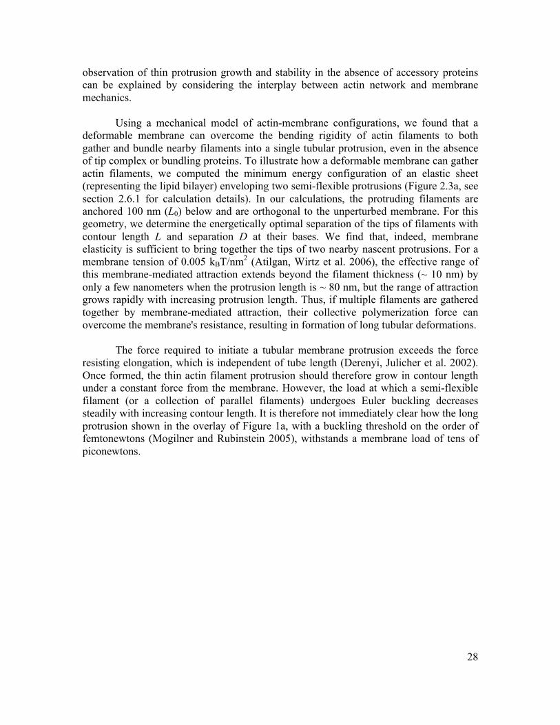
28
observation of thin protrusion growth and stability in the absence of accessory proteins can be explained by considering the interplay between actin network and membrane mechanics.
Using a mechanical model of actin-membrane configurations, we found that a deformable membrane can overcome the bending rigidity of actin filaments to both gather and bundle nearby filaments into a single tubular protrusion, even in the absence of tip complex or bundling proteins. To illustrate how a deformable membrane can gather actin filaments, we computed the minimum energy configuration of an elastic sheet (representing the lipid bilayer) enveloping two semi-flexible protrusions (Figure 2.3a, see section 2.6.1 for calculation details). In our calculations, the protruding filaments are anchored 100 nm (L0) below and are orthogonal to the unperturbed membrane. For this geometry, we determine the energetically optimal separation of the tips of filaments with contour length L and separation D at their bases. We find that, indeed, membrane elasticity is sufficient to bring together the tips of two nearby nascent protrusions. For a membrane tension of 0.005 kBT/nm2 (Atilgan, Wirtz et al. 2006), the effective range of this membrane-mediated attraction extends beyond the filament thickness (~ 10 nm) by only a few nanometers when the protrusion length is ~ 80 nm, but the range of attraction grows rapidly with increasing protrusion length. Thus, if multiple filaments are gathered together by membrane-mediated attraction, their collective polymerization force can overcome the membrane's resistance, resulting in formation of long tubular deformations.
The force required to initiate a tubular membrane protrusion exceeds the force
resisting elongation, which is independent of tube length (Derenyi, Julicher et al. 2002). Once formed, the thin actin filament protrusion should therefore grow in contour length under a constant force from the membrane. However, the load at which a semi-flexible filament (or a collection of parallel filaments) undergoes Euler buckling decreases steadily with increasing contour length. It is therefore not immediately clear how the long protrusion shown in the overlay of Figure 1a, with a buckling threshold on the order of femtonewtons (Mogilner and Rubinstein 2005), withstands a membrane load of tens of piconewtons.
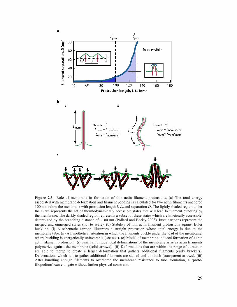
29
Figure 2.3 Role of membrane in formation of thin actin filament protrusions. (a) The total energy associated with membrane deformation and filament bending is calculated for two actin filaments anchored 100 nm below the membrane with protrusion length L-L0 and separation D. The lightly shaded region under the curve represents the set of thermodynamically accessible states that will lead to filament bundling by the membrane. The darkly shaded region represents a subset of these states which are kinetically accessible, determined by the branching distance of ~100 nm (Pollard and Borisy 2003). Inset cartoons represent the merged and unmerged states (not to scale). (b) Stability of thin actin filament protrusions against Euler buckling. (i) A schematic cartoon illustrates a straight protrusion whose total energy is due to the membrane tube. (ii) A hypothetical situation in which the filaments buckle under the load of the membrane, where buckling is energetically unfavorable (see text). (c) Model of membrane-induced formation of a thin actin filament protrusion. (i) Small amplitude local deformations of the membrane arise as actin filaments polymerize against the membrane (solid arrows). (ii) Deformations that are within the range of attraction are able to merge to create a larger deformation that gathers additional filaments (curly brackets). Deformations which fail to gather additional filaments are stalled and diminish (transparent arrows). (iii) After bundling enough filaments to overcome the membrane resistance to tube formation, a ‘proto-filopodium’ can elongate without further physical constraint.
30
The balance of forces that suggests buckling of long protrusions neglects the fact that a membrane tube must bend with the deflections of the filaments it encloses. While the additional bending energy from the curvature of the membrane tube is relatively small (Derenyi, Julicher et al. 2002), the steric constraint that it must follow the curvature of the enclosed actin filaments has important repercussions. For the case of a straight protrusion, the membrane energy is Emem = fmemLmem where fmem is the membrane resistance force and Lmem is the length of the membrane tube, and the bending energy of the filaments, Ebundle, is zero (Figure 2.3b i). For the case of a buckled protrusion, the initial stages of buckling would involve membrane configurations conformal to the enclosed filaments. Because the membrane bends and does not shorten in these configurations, Emem exceeds fmemLmem while Ebundle is also positive (Figure 2.3b ii). Thus, the total energy of the deformation is lower for a straight protrusion than for a buckled protrusion (see section 2.6.3, (Pronk, Geissler et al. 2008)).
The resulting stability against lateral deflections is consistent with our observation
of long, straight actin filament protrusions as well as other long filopodia observed in vivo (Wood, Jacinto et al. 2002; Onfelt, Nedvetzki et al. 2006). This stabilization of membrane-enclosed filaments against buckling has in fact been observed for microtubules protruding from the interior of a liposome (Fygenson, Elbaum et al. 1997). Strikingly, these microtubules bend substantially inside the liposome body, but remain straight where surrounded by membrane tubes.
Our elastic model for membrane-induced bundling points to the protrusion length
of individual actin filaments as a key parameter regulating the incidence of the filopodia-like protrusions. According to our calculations, increasing the protrusion length while holding membrane tension fixed should increase both the range and strength of lateral attraction between filaments. The maximum protrusion length is typically thought to be determined by a balance between polymerization force and membrane resistance (Figure 2.3a). The force-limited length resulting from this balance, while limiting on average, could be transiently exceeded due to fluctuations in the network’s internal stress. But it is also possible that single-filament protrusions rarely reach this limit before branching disrupts membrane configurations that favor bundling. In this case the branch-limited maximum protrusion length of a single filament is determined instead by the relative kinetics of branching and polymerization.
If protrusion lengths are branch limited, our model would predict that shorter
protrusion lengths created by increased branching would reduce the likelihood of the thin actin filament protrusions. Indeed, when Arp2/3 complex concentration was increased by three fold while actin concentration was held constant, we observed a ~ 60% reduction in the frequency of filopodia formation, consistent with expectations from the model and confirming that filament protrusions lengths are limited by kinetics rather than polymerization force. Conversely, the frequency of filopodium-like structures did not decrease when Arp2/3 complex concentration was decreased to as low as 10 nM (data not shown).
31
A second key parameter in the elastic model is membrane tension σ. Our calculations indicate that decreasing σ, while keeping fixed, should reduce the membrane’s ability to gather filaments. Consistent with this prediction, we found that decreasing membrane tension by increasing solution osmolarity, while keeping concentrations of Arp2/3 complex and free actin monomer fixed, indeed lowered the frequency of forming thin actin filament protrusions by ~ 15% (see section 2.6.2).
Based on in vitro experiments and electron microscopy studies, Svitkina et al. proposed the convergent elongation model to describe the formation of filopodia from lamellipodia (Svitkina, Bulanova et al. 2003). This model describes the transition from branched to parallel filament architecture in two stages: (i) elongation and lateral association of filaments by tip complex proteins with anti-capping and barbed-end clustering activities, followed by (ii) stabilization of the thin actin array of actin filaments by bundling proteins. Recent studies have identified additional filopodium regulators (Mattila, Pykalainen et al. 2007; Sigal, Quintero et al. 2007), and other studies have challenged whether an underlying dendritic network is necessary for filopodium formation (Snapper, Takeshima et al. 2001; Steffen, Faix et al. 2006). This debate has focused solely on the role of actin-binding proteins (Gupton and Gertler 2007), overlooking the question of whether and how the membrane could play a role in filament organization during filopodium formation. The unexpected formation and stability of the filopodium-like protrusions in our in vitro system suggests that parallel actin-based structures are a natural result of the interaction between growing actin networks and an elastic membrane. Our results demonstrate that the lipid bilayer alone can facilitate free barbed-end clustering and alignment of filaments that can continue to elongate without buckling under the membrane load.
2.4 Conclusions
Formation of filopodium-like structures without bundling proteins or tip-complex
proteins suggests that membrane-induced alignment of actin filaments could facilitate formation of filopodia in cells (Figure 2.3c). We propose a model in which actin filaments are routinely brought together by elastic interactions with the membrane, forming a ‘proto-filopodium’, which sets the stage for the formation of a mature filopodium through the participation of actin-binding proteins. Specifically, actin filaments initially gathered by the membrane would be stabilized by tip-complex proteins that associate with the filament ends to prevent capping and by bundling proteins such as fascin that reinforce parallel filament organization during membrane protrusion. In this way, accessory proteins exploit membrane-induced organization of actin filaments to provide regulatory control of protrusions but are not required for their initial formation. The minimal system for generating thin actin filament protrusions presented here would serve as an excellent platform for investigating and evaluating the role of various proteins required for filopodia formation in vivo; however, electron microscopy images of the actin filaments in these protrusions will be required to definitively confirm their organization. In a broader context, this work suggests that the mechanical properties of
32
the plasma membrane may play a critical role in organizing the cytoskeletal filaments that drive many forms of cellular shape change. 2.5 Materials and Methods 2.5.1 Protein Expression, Purification, and Fluorescent Labeling
Actin was purified from rabbit muscle acetone powder as described by Spudich and Watt (Spudich and Watt 1971). Fluorescently-labeled actin was prepared by reacting actin with AF350, AF488, or AF555 maleimide (Molecular Probes). His6-HA-tagged ΔEVH1 N-WASP was over-expressed in Escherichia coli and purified using Nickel affinity chromatography and HiTRAP Q (Amersham) (Papayannopoulos, Co et al. 2005). Arp2/3 complex was purified from bovine brains (Egile, Loisel et al. 1999). AF488 N-WASP and AF488 Arp2/3 complex were labeled with AF488 maleimide. Protein purities were checked by sodium dodecyl sulfate polyacrylamide gel electrophoresis. Protein concentrations were determined by protein absorbance and BCA assays. N-WASP and Arp2/3 complex activities were confirmed by using in vitro bead motility assay with N-WASP-coated microspheres (Wiesner, Helfer et al. 2003). AF488 capping protein, Cdc42/RhoGDI, and intersectin DH-PH were expressed in E. coli and were gifts from Jack Taunton. 2.5.2 GUV Formation
GUVs were prepared in sucrose solution from synthetic and natural lipids as described previously (Liu and Fletcher 2006). All lipids used were purchased from Avanti Polar Lipids unless otherwise stated. Three compositions were used primarily and all nucleated actin equally well. For canonical N-WASP activation with Cdc42 and PIP2, GUVs containing 75% egg PC, 20% DOPS, and 5% brain PIP2 were used (Co, Wong et al. 2007). For some experiments, phase separating GUVs containing 24.3% DOPC, 35% DPPC, 40% cholesterol, and 0.7% BODIPY TMR PIP2 were used where actin nucleation occurs robustly with BODIPY TMR PIP2 alone (in the absence of Cdc42). DOGS-NiNTA vesicles, which binds His-tagged N-WASP, containing vesicles have 95% egg PC and 5% DOGS-NiNTA. Refer to section 2.6.7 for specific conditions used in each experiment. BODIPY TMR PIP2 was purchased from Echelon Biosciences (Salt Lake City, Utah). For experiments where visualization of membrane was desired, either fluorescent lipid fluorescein-DOPE or C5 C8 BODIPY was used. 2.5.3 In vitro Reconstitution of Thin Actin Filament Protrusions
GUVs were pre-incubated with 4 µM of N-WASP for a minimum of 10 minutes prior to initiating the reaction. For experiments requiring Cdc42, 0.75 µM of Cdc42/RhoGDI complex, 0.18 µM DH-PH, and 0.5 µM GTPγS were included during the pre-incubation step. Assembly of actin on GUVs was initiated by diluting the vesicle solution 10-fold into actin and Arp2/3 complex. The final mixture contains ~8.5 µM G-actin, ~160 nM Arp2/3 complex, and ~400 nM N-WASP in actin polymerization buffer.
33
Osmolarity of the final protein mixtures was matched to the vesicles to within 5%. Large osmolarity differences are otherwise adjusted by varying the final salt concentration of the polymerization buffer (between 1x to 2 x), which has no effect on the extent of actin polymerization. The protein vesicle mixture was added to a homemade chamber (0.1mm x 5mm x 20mm) consisting of a glass coverslip adhered to a glass slide using double-sided tape, then sealed with VALAP (1:1:1 of vaseline, lanoline, and paraffin) before imaging. 2.5.4 Microscopy
Actin associated vesicles were imaged by phase contrast and epifluorescence microscopy using a 100x 1.25 NA objective for most studies on an inverted microscope (Zeiss Axiovert 200) equipped with motorized stage control and a back-illuminated cooled CCD camera. All light microscopy operations were driven by Metamorph imaging software. Laser scanning confocal microscopy was used for protein localization and photo-bleaching experiments (Zeiss LSM 510). A small region along a single proto-filopodium was bleached using a 63x objective 1.25 NA with 18 mW argon laser at 488 nm and 458 nm. Fluorescence recovery was monitored over 10 min. Spinning disk confocal microscopy was also used to image actin networks on GUV. 2.5.5 Data Analysis and Modeling
Linescans of AF555 actin, AF488 Arp2/3 complex, and AF488 capping proteins along proto-filopodia were performed in Metamorph. Raw fluorescence intensity was corrected for background fluorescence and normalized with respect to the base of proto-filopodia (dendritic networks) for actin. For Arp2/3 complex and capping proteins, the linescans were further divided by the intensity traces for actin to represent the relative localization of actin binding proteins to actin.
For analysis of photobleaching experiment, fluorescence intensity across the length of the proto-filopodium was tracked over time. Regions of the fluorescence linescan were fitted to a sigmoidal function. The inflection point is identified and used as a metric to track movements of the marked positions.
Growth rate of filopodium-like protrusions was measured from phase contrast images. Integrated fluorescence actin intensity associated with the GUV was collected simultaneously with proto-filopodium elongation. After correcting for photo-bleaching and background fluorescence, the actin “polymerization curve” was fit to a sigmoid and time-dependent actin concentrations were interpolated (see section 2.6.4). 2.5.6 Image Processing
All images were processed using Adobe Photoshop. Any brightness or contrast adjustments were uniformly applied to the entire image field and stack.
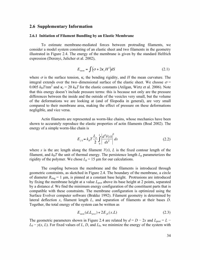
34
2.6 Supplementary Information 2.6.1 Initiation of Filament Bundling by an Elastic Membrane
To estimate membrane-mediated forces between protruding filaments, we consider a model system consisting of an elastic sheet and two filaments in the geometry illustrated in Figure 2.4. The energy of the membrane is given by the standard Helfrich expression (Derenyi, Julicher et al. 2002),
€
Emem = σ + 2κcH2( )∫ dS (2.1)
where σ is the surface tension, κc the bending rigidity, and H the mean curvature. The integral extends over the two–dimensional surface of the elastic sheet. We choose σ = 0.005 kBT/nm2 and κc = 20 kBT for the elastic constants (Atilgan, Wirtz et al. 2006). Note that this energy doesn’t include pressure terms: this is because not only are the pressure differences between the inside and the outside of the vesicles very small, but the volume of the deformations we are looking at (and of filopodia in general), are very small compared to their membrane area, making the effect of pressure on these deformations negligible, and vice versa.
Actin filaments are represented as worm-like chains, whose mechanics have been shown to accurately reproduce the elastic properties of actin filaments (Boal 2002). The energy of a simple worm-like chain is
(2.2)
where s is the arc length along the filament , L is the fixed contour length of the filament, and kBT the unit of thermal energy. The persistence length Lp parameterizes the rigidity of the polymer. We chose Lp = 15 µm for our calculations.
The coupling between the membrane and the filaments is introduced through geometric constraints, as sketched in Figure 2.4. The boundary of the membrane, a circle of diameter Rring = 1 µm, is pinned at a constant base height. Protrusions are introduced by fixing the membrane height at a value Lprot above its base height at 2 points, separated by a distance d. We find the minimum energy configuration of the constituent parts that is compatible with these constraints. The membrane configuration is optimized using the Surface Evolver computer software (Brakke 1992). Filament geometry is determined by lateral deflection x, filament length L, and separation of filaments at their bases D. Together, the total energy of the system can be written as
€
Emem (d,Lprot ) + 2E fil (x,L) (2.3)
The geometric parameters shown in Figure 2.4 are related by d = D − 2x and Lprot = L − L0 − y(x, L). For fixed values of L, D, and L0, we minimize the energy of the system with
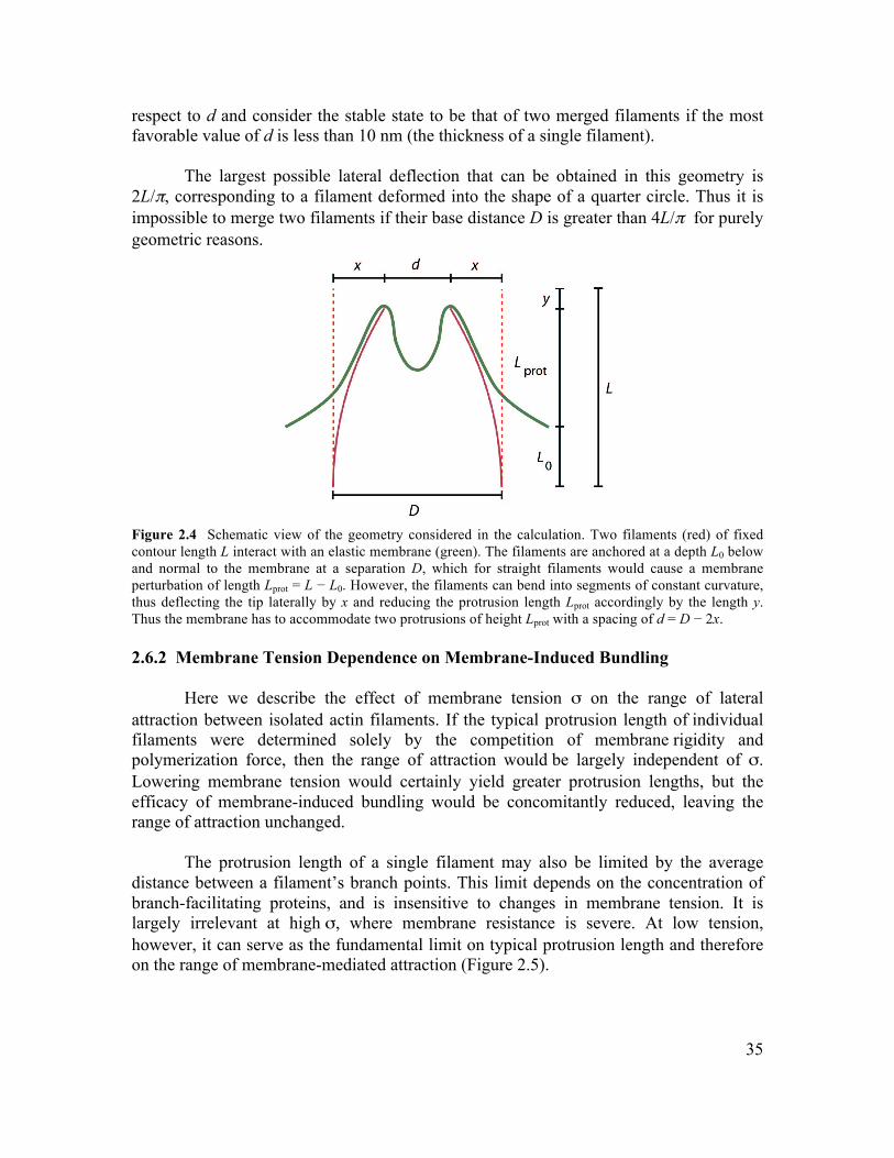
35
respect to d and consider the stable state to be that of two merged filaments if the most favorable value of d is less than 10 nm (the thickness of a single filament).
The largest possible lateral deflection that can be obtained in this geometry is 2L/π, corresponding to a filament deformed into the shape of a quarter circle. Thus it is impossible to merge two filaments if their base distance D is greater than 4L/π for purely geometric reasons.
Figure 2.4 Schematic view of the geometry considered in the calculation. Two filaments (red) of fixed contour length L interact with an elastic membrane (green). The filaments are anchored at a depth L0 below and normal to the membrane at a separation D, which for straight filaments would cause a membrane perturbation of length Lprot = L − L0. However, the filaments can bend into segments of constant curvature, thus deflecting the tip laterally by x and reducing the protrusion length Lprot accordingly by the length y. Thus the membrane has to accommodate two protrusions of height Lprot with a spacing of d = D − 2x. 2.6.2 Membrane Tension Dependence on Membrane-Induced Bundling Here we describe the effect of membrane tension σ on the range of lateral attraction between isolated actin filaments. If the typical protrusion length of individual filaments were determined solely by the competition of membrane rigidity and polymerization force, then the range of attraction would be largely independent of σ. Lowering membrane tension would certainly yield greater protrusion lengths, but the efficacy of membrane-induced bundling would be concomitantly reduced, leaving the range of attraction unchanged.
The protrusion length of a single filament may also be limited by the average distance between a filament’s branch points. This limit depends on the concentration of branch-facilitating proteins, and is insensitive to changes in membrane tension. It is largely irrelevant at high σ, where membrane resistance is severe. At low tension, however, it can serve as the fundamental limit on typical protrusion length and therefore on the range of membrane-mediated attraction (Figure 2.5).
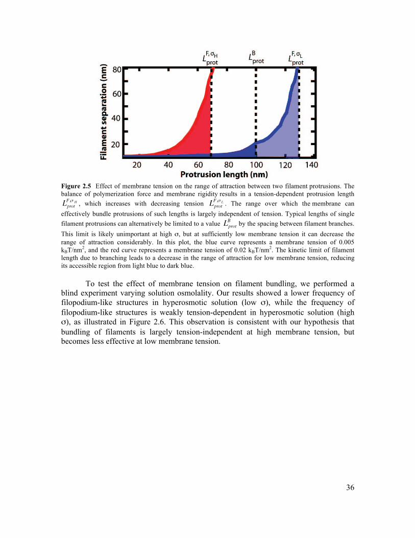
36
Figure 2.5 Effect of membrane tension on the range of attraction between two filament protrusions. The balance of polymerization force and membrane rigidity results in a tension-dependent protrusion length
, which increases with decreasing tension . The range over which the membrane can effectively bundle protrusions of such lengths is largely independent of tension. Typical lengths of single filament protrusions can alternatively be limited to a value by the spacing between filament branches. This limit is likely unimportant at high σ, but at sufficiently low membrane tension it can decrease the range of attraction considerably. In this plot, the blue curve represents a membrane tension of 0.005 kBT/nm2, and the red curve represents a membrane tension of 0.02 kBT/nm2. The kinetic limit of filament length due to branching leads to a decrease in the range of attraction for low membrane tension, reducing its accessible region from light blue to dark blue.
To test the effect of membrane tension on filament bundling, we performed a blind experiment varying solution osmolality. Our results showed a lower frequency of filopodium-like structures in hyperosmotic solution (low σ), while the frequency of filopodium-like structures is weakly tension-dependent in hyperosmotic solution (high σ), as illustrated in Figure 2.6. This observation is consistent with our hypothesis that bundling of filaments is largely tension-independent at high membrane tension, but becomes less effective at low membrane tension.
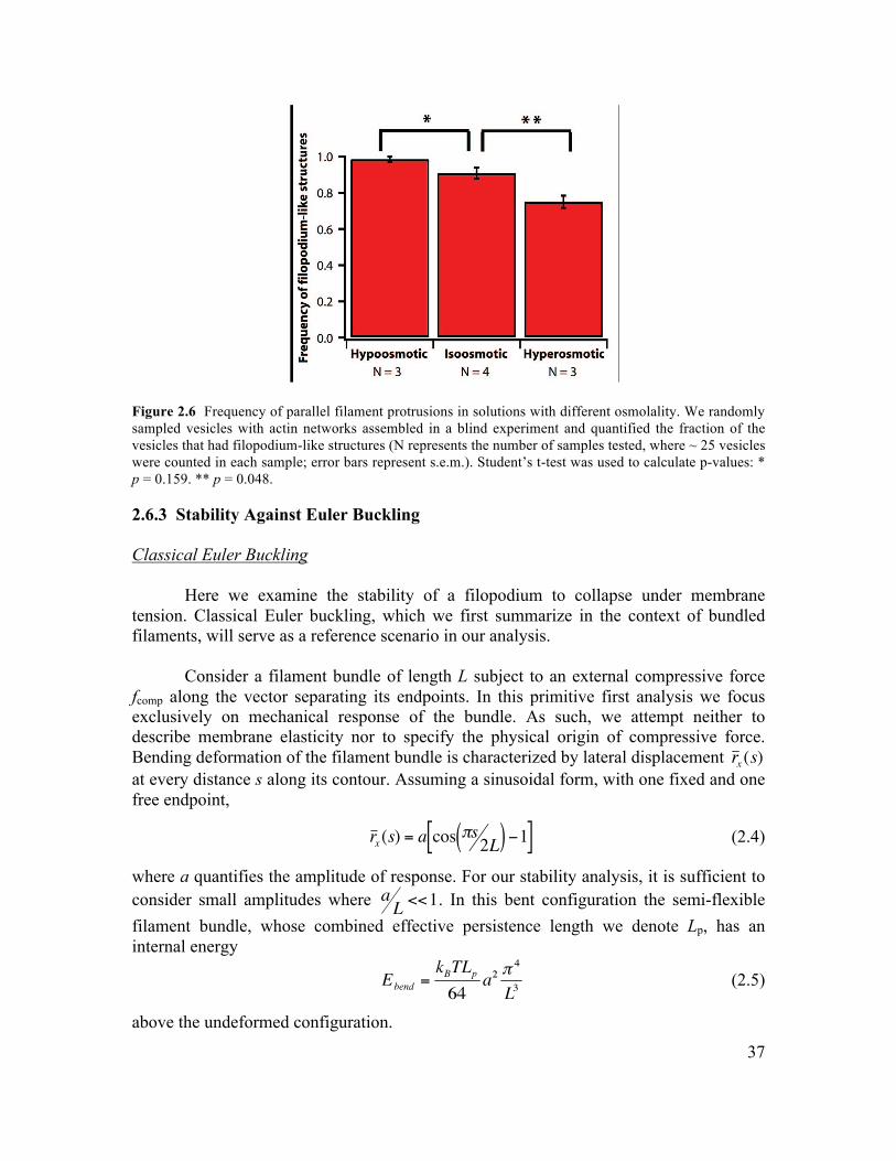
37
Figure 2.6 Frequency of parallel filament protrusions in solutions with different osmolality. We randomly sampled vesicles with actin networks assembled in a blind experiment and quantified the fraction of the vesicles that had filopodium-like structures (N represents the number of samples tested, where ~ 25 vesicles were counted in each sample; error bars represent s.e.m.). Student’s t-test was used to calculate p-values: * p = 0.159. ** p = 0.048. 2.6.3 Stability Against Euler Buckling Classical Euler Buckling
Here we examine the stability of a filopodium to collapse under membrane tension. Classical Euler buckling, which we first summarize in the context of bundled filaments, will serve as a reference scenario in our analysis.
Consider a filament bundle of length L subject to an external compressive force fcomp along the vector separating its endpoints. In this primitive first analysis we focus exclusively on mechanical response of the bundle. As such, we attempt neither to describe membrane elasticity nor to specify the physical origin of compressive force. Bending deformation of the filament bundle is characterized by lateral displacement at every distance s along its contour. Assuming a sinusoidal form, with one fixed and one free endpoint,
€
r x (s) = a cos πs2L( ) −1[ ] (2.4)
where a quantifies the amplitude of response. For our stability analysis, it is sufficient to consider small amplitudes where . In this bent configuration the semi-flexible filament bundle, whose combined effective persistence length we denote Lp, has an internal energy
(2.5)
above the undeformed configuration.
38
The external potential of compression offsets this energetic penalty by
(2.6)
The sign of change in total energy,
€
ΔEtot = Ebend + ΔEcomp , determines whether deformation on a given amplitude will occur spontaneously. Summing equations (2.5) and (2.6), we obtain
€
ΔEtot = Ebend + ΔEcomp (2.7)
€
=kBTLp
64a2 π
4
L3−fcomp16
a2 π2
L< 0
Here we have defined the Euler buckling force . Forces of compression
below this threshold induce no lateral displacement (in this zero-temperature approximation), while larger forces deform the filament bundle at all amplitudes. In other
words, for , the filament buckles. At this force, the bent state of
the filament is more favorable at any deformation amplitude a, and the filament buckles.
In the following two sections we consider the possible roles of membrane in this
scenario when the semiflexible filament bundle is enclosed by a membrane tube. We do so for two different membrane configurations, corresponding to Figures 2.7b and 2.7c. Case I: The Membrane Tube Shortens as the Filament Buckles
In the hypothetical membrane deformation, shown in Figure 2.7b, the membrane retains its straight cylindrical shape, and in effect interacting with the bundle only at its tip. The energy associated with the membrane tube is linearly proportional to the membrane length Lmem
€
Emem = fmemLmem (2.8)
where fmem = πκ/R + 2πRσ.
(2.9)
Comparing with equation (2.6), we see that in this case the membrane acts solely as a source of compressive force. The change in total energy thus has a form similar to equation (2.7)
(2.10)
39
According to this result, sufficiently long protrusions,
€
L > π 2kBTLp /4 fmem should undergo classical Euler buckling (instability to compression at all amplitudes). Closer scrutiny of the filopodium geometry, however, reveals that configurations of the membrane tubule and filament bundle are incompatible in this configuration. Specifically, without deforming laterally the membrane tube would be penetrated by the bent filament bundle, as illustrated in Figure 2.7b. Case II: The Membrane Tube Remains the Same Length as the Filament Buckles
In a physically sensible configuration the membrane would adapt to the bent bundle’s shape. Specifically, for small displacement of a long protrusion, the membrane sheath deforms together with the filaments it surrounds, as sketched in Figure 2.7c. As a result of this constraint, contour length of the tube’s axis is not diminished by bending the filament bundle. Surface area of the membrane tube is thus essentially unchanged, providing no energetic reward for bending. In fact the membrane’s energy can only increase due to bending. Without an energetically advantageous membrane response, filopodium compression is expressly unfavorable,
(2.11)
We thus predict stability of even very long filopodia to small longitudinal deformations. Interestingly, the membrane in this case acts to stabilize against buckling while still compressing the filament along its contour. It should also be stressed that this stability against buckling is simply due to the fact that the driving force that normally leads to buckling is absent here: it is not the result of an inherent property of the filament bundle.
In this argument we have assumed that the filopodium diameter R is small
compared to its length. If space were available for substantial rearrangement of the filament bundle inside the membrane, it would be important to consider other possible modes of collapse. An analysis of such modes, which is beyond the scope of this manuscript, indicates that filopodia longer than a few tube diameters should be stable to compression.
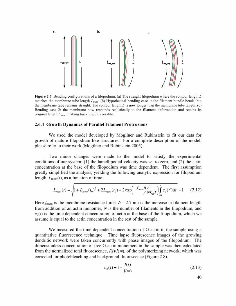
40
Figure 2.7 Bending configurations of a filopodium. (a) The straight filopodium where the contour length L matches the membrane tube length Lmem. (b) Hypothetical bending case 1: the filament bundle bends, but the membrane tube remains straight. The contour length L is now longer than the membrane tube length. (c) Bending case 2: the membrane now responds realistically to the filament deformation and retains its original length Lmem, making buckling unfavorable. 2.6.4 Growth Dynamics of Parallel Filament Protrusions
We used the model developed by Mogilner and Rubinstein to fit our data for growth of mature filopodium-like structures. For a complete description of the model, please refer to their work (Mogilner and Rubinstein 2005).
Two minor changes were made to the model to satisfy the experimental conditions of our system: (1) the lamellipodial velocity was set to zero, and (2) the actin concentration at the base of the filopodium was time dependent. The first assumption greatly simplified the analysis, yielding the following analytic expression for filopodium length, Lmem(t), as a function of time.
€
Lmem (t) = 1+ Lmem (t0)2 + 2Lmem (t0) + 2exp − fmemδ NkBT
⎛ ⎝ ⎜ ⎞
⎠ ⎟ c0(t')dt't0
t
∫ −1 (2.12)
Here fmem is the membrane resistance force, δ = 2.7 nm is the increase in filament length from addition of an actin monomer, N is the number of filaments in the filopodium, and c0(t) is the time dependent concentration of actin at the base of the filopodium, which we assume is equal to the actin concentration in the rest of the sample.
We measured the time dependent concentration of G-actin in the sample using a quantitative fluorescence technique. Time lapse fluorescence images of the growing dendritic network were taken concurrently with phase images of the filopodium. The dimensionless concentration of free G-actin monomers in the sample was then calculated from the normalized total fluorescence, I(t)/I(∞), of the polymerizing network, which was corrected for photobleaching and background fluorescence (Figure 2.8).
(2.13)
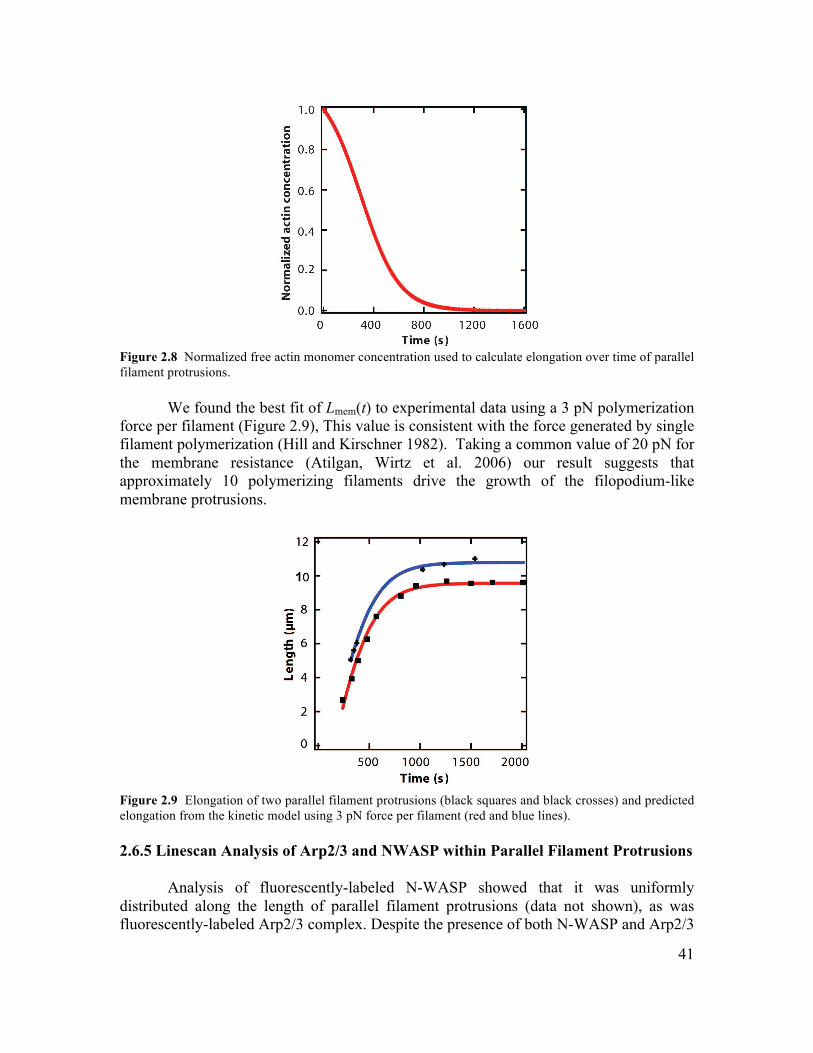
41
Figure 2.8 Normalized free actin monomer concentration used to calculate elongation over time of parallel filament protrusions.
We found the best fit of Lmem(t) to experimental data using a 3 pN polymerization force per filament (Figure 2.9), This value is consistent with the force generated by single filament polymerization (Hill and Kirschner 1982). Taking a common value of 20 pN for the membrane resistance (Atilgan, Wirtz et al. 2006) our result suggests that approximately 10 polymerizing filaments drive the growth of the filopodium-like membrane protrusions.
Figure 2.9 Elongation of two parallel filament protrusions (black squares and black crosses) and predicted elongation from the kinetic model using 3 pN force per filament (red and blue lines). 2.6.5 Linescan Analysis of Arp2/3 and NWASP within Parallel Filament Protrusions
Analysis of fluorescently-labeled N-WASP showed that it was uniformly distributed along the length of parallel filament protrusions (data not shown), as was fluorescently-labeled Arp2/3 complex. Despite the presence of both N-WASP and Arp2/3
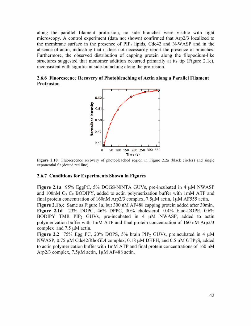
42
along the parallel filament protrusion, no side branches were visible with light microscopy. A control experiment (data not shown) confirmed that Arp2/3 localized to the membrane surface in the presence of PIP2 lipids, Cdc42 and N-WASP and in the absence of actin, indicating that it does not necessarily report the presence of branches. Furthermore, the observed distribution of capping protein along the filopodium-like structures suggested that monomer addition occurred primarily at its tip (Figure 2.1c), inconsistent with significant side-branching along the protrusion. 2.6.6 Fluorescence Recovery of Photobleaching of Actin along a Parallel Filament Protrusion
Figure 2.10 Fluorescence recovery of photobleached region in Figure 2.2a (black circles) and single exponential fit (dotted red line). 2.6.7 Conditions for Experiments Shown in Figures Figure 2.1a 95% EggPC, 5% DOGS-NiNTA GUVs, pre-incubated in 4 µM NWASP and 100nM C5 C8 BODIPY, added to actin polymerization buffer with 1mM ATP and final protein concentration of 160nM Arp2/3 complex, 7.5µM actin, 1µΜ AF555 actin. Figure 2.1b,c Same as Figure 1a, but 300 nM AF488 capping protein added after 30min. Figure 2.1d 23% DOPC, 46% DPPC, 30% cholesterol, 0.4% Fluo-DOPE, 0.6% BODIPY TMR PIP2 GUVs, pre-incubated in 4 µM NWASP, added to actin polymerization buffer with 1mM ATP and final protein concentration of 160 nM Arp2/3 complex and 7.5 µM actin. Figure 2.2 75% Egg PC, 20% DOPS, 5% brain PIP2 GUVs, preincubated in 4 µM NWASP, 0.75 µM Cdc42/RhoGDI complex, 0.18 µM DHPH, and 0.5 µM GTPγS, added to actin polymerization buffer with 1mM ATP and final protein concentrations of 160 nM Arp2/3 complex, 7.5µM actin, 1µΜ AF488 actin.
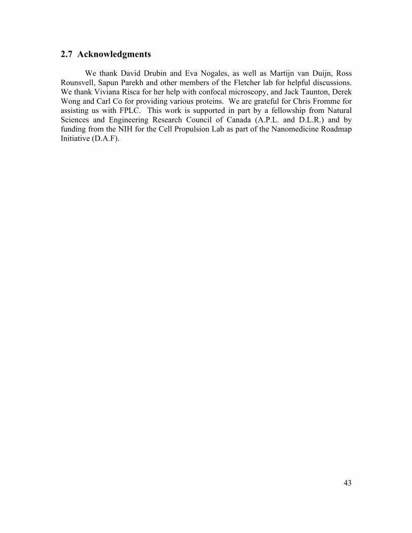
43
2.7 Acknowledgments We thank David Drubin and Eva Nogales, as well as Martijn van Duijn, Ross Rounsvell, Sapun Parekh and other members of the Fletcher lab for helpful discussions. We thank Viviana Risca for her help with confocal microscopy, and Jack Taunton, Derek Wong and Carl Co for providing various proteins. We are grateful for Chris Fromme for assisting us with FPLC. This work is supported in part by a fellowship from Natural Sciences and Engineering Research Council of Canada (A.P.L. and D.L.R.) and by funding from the NIH for the Cell Propulsion Lab as part of the Nanomedicine Roadmap Initiative (D.A.F).
44
Chapter 3: Unilamellar Vesicle Formation and Encapsulation by Microfluidic Jetting
Reproduced by permission of the National Academy of Sciences of the USA. Jeanne C. Stachowiak, David L. Richmond, Thomas H. Li, Allen P. Liu, Sapun H.
Parekh, and Daniel A. Fletcher (2008). “Unilamellar Vesicle Formation and Encapsulation by Microfluidic Jetting.” Proceedings of the National Academy of
Sciences 105(12): 4697-4702.
© 2008 by The National Academy of Sciences of the USA
45
3.1 Abstract
Compartmentalization of biomolecules within lipid membranes is a fundamental requirement of living systems and an essential feature of many pharmaceutical therapies. However, applications of membrane-enclosed solutions of proteins, DNA, or biologically active compounds have been limited by the difficulty of forming unilamellar vesicles with controlled contents in a repeatable manner. Here we demonstrate a method for simultaneously creating and loading GUVs using a pulsed microfluidic jet. Akin to blowing a bubble, the microfluidic jet deforms a planar lipid bilayer into a vesicle that is filled with solution from the jet and separates from the planar bilayer. In contrast to existing techniques, our method rapidly generates multiple monodisperse, unilamellar vesicles containing solutions of unrestricted composition and molecular weight. Using the microfluidic jetting technique, we demonstrate repeatable encapsulation of 500-nm particles into GUVs and show that functional pore proteins can be incorporated into the vesicle membrane to mediate transport. The ability of microfluidic jetting to controllably encapsulate solutions inside of GUVs creates new opportunities for the study and use of compartmentalized biomolecular systems in science, industry and medicine. 3.2 Introduction
Encapsulation of enzymes in lipid vesicles was first attempted by Sessa and Weissmann in 1970 (Sessa and Weissman.G 1970). Since then, vesicles encapsulating biologically-active compounds have been used as chemical micro-reactors (Walde 1996), delivery vehicles for pharmaceuticals (Lasic and Papahadjopoulos 1995), and platforms for synthetic biological systems (Hanczyc, Fujikawa et al. 2003; Chen, Roberts et al. 2004). Since mixtures of lipids and biomolecules will not spontaneously organize into solution-encapsulating vesicles of defined composition and size, several methods have been devised to form and load vesicles including swelling (Reeves and Dowben 1969), extrusion (Olson, Hunt et al. 1979), electroformation (Angelova and Dimitrov 1986), electroinjection (Karlsson, Nolkrantz et al. 2000), and reverse evaporation and emulsion (Szoka and Papahadjopoulos 1978; Pautot, Frisken et al. 2003).
Among the most important properties of a vesicle formation and loading technique are (i) control of membrane unilamellarity, (ii) control of vesicle size, and (iii) control of internal solution concentration without solute-specific selectivity. Furthermore, practical applications of vesicle encapsulation require high encapsulation efficiency to minimize needed solution volume, high-throughput formation, and the ability to examine the vesicle and any associated reactions immediately after loading. Furthermore, in applications to study in vitro protein assemblies (Liu and Fletcher 2006) and cell-like membrane deformations (Miyata, Nishiyama et al. 1999), GUVs with diameters > 10 µm are desirable to facilitate direct visualization of internal behavior by light microscopy.
Although each existing vesicle formation technique achieves some of these criteria, none enables vesicle formation and encapsulation with all of these properties.
46
For example, swelling typically results in the formation of multilamellar vesicles (MLVs) that vary widely in size and encapsulate with low, solute-specific efficiency (Walde 1996). Electroformation can produce GUVs with diameters above 10 µm. However, vesicle diameter is not controlled, and the technique is restricted to low ionic strength conditions, limiting its applicability for encapsulation of biomolecules (Bucher, Fischer et al. 1998). The size uniformity of GUVs and the unilamellarity of MLVs made by several techniques (Reeves and Dowben 1969; Szoka and Papahadjopoulos 1978; Angelova and Dimitrov 1986) can be greatly enhanced by extruding the vesicles through filters with sub-micron pores, though the resulting vesicles are limited to the size of the pores and have the same internal composition as the original vesicles (Colletier, Chaize et al. 2002). The reverse emulsion technique, offers the advantage of solute-independent encapsulation efficiency. However the size of vesicles produced by reverse emulsion is not directly controllable and throughput is limited (Pautot, Frisken et al. 2003). Recently, several groups have reported the high-throughput production of monodisperse single and double emulsion structures using microdevices that hydrodynamically focus fluid streams (Atencia and Beebe 2005; Utada, Lorenceau et al. 2005; Gunther and Jensen 2006) and pulsed microfluidic jets that deform interfaces (Funakoshi, Suzuki et al. 2007), though none have been shown to form unilamellar vesicles, an essential requirement for many applications.
Here we demonstrate the formation and loading of GUVs by microfluidic jetting-induced deformation of a planar lipid bilayer (Figure 3.1a). This technique relies on a precisely controlled pulsatile liquid jet directed into a unilamellar lipid bilayer formed between two aqueous phases (Figure 3.1b). One GUV is formed for each pulse of the liquid jet against the lipid bilayer, which remains intact after the vesicle is formed, and multiple monodisperse vesicles are formed by repeated pulses against the same lipid bilayer (Figure 3.1c). Using high-speed video microscopy, we examine the vesicle formation process to investigate the fluid-membrane interactions which determine vesicle size and enable vesicle separation from the planar bilayer. Finally, we encapsulate a solution of 500-nm diameter particles and demonstrate protein pore-mediated transport of solutes across vesicle boundaries. 3.3 Results and Discussion
Vesicles produced by microfluidic jetting against a planar lipid bilayer are highly uniform in size (average diameter = 208 µm based on a total measured population of 46 GUVs, varying by 2-3% for a given series of pulses and by less than 7% for different planar bilayers and nozzles of nominally the same size, Figure 3.1c-d) and robust (outlasting the observation time of several hours after formation). Multiple vesicles can be created in rapid succession since lipid molecules capable of replenishing the planar bilayer are available in high concentration (in the supporting oil phase around the black film). High throughput formation of 1,000s of vesicles per minute is feasible based on a formation time of 5ms per GUV but was not the objective of this work. Since the vesicle is created from a single lipid bilayer (Funakoshi, Suzuki et al. 2006). we expect only unilamellar vesicles to be formed with this technique. Furthermore, since this technique relies on large (relative to molecular radii) physical deformations of a planar lipid bilayer
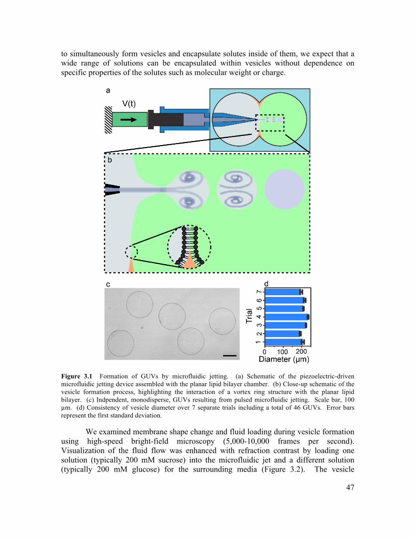
47
to simultaneously form vesicles and encapsulate solutes inside of them, we expect that a wide range of solutions can be encapsulated within vesicles without dependence on specific properties of the solutes such as molecular weight or charge.
Figure 3.1 Formation of GUVs by microfluidic jetting. (a) Schematic of the piezoelectric-driven microfluidic jetting device assembled with the planar lipid bilayer chamber. (b) Close-up schematic of the vesicle formation process, highlighting the interaction of a vortex ring structure with the planar lipid bilayer. (c) Indpendent, monodisperse, GUVs resulting from pulsed microfluidic jetting. Scale bar, 100 µm. (d) Consistency of vesicle diameter over 7 separate trials including a total of 46 GUVs. Error bars represent the first standard deviation.
We examined membrane shape change and fluid loading during vesicle formation using high-speed bright-field microscopy (5,000-10,000 frames per second). Visualization of the fluid flow was enhanced with refraction contrast by loading one solution (typically 200 mM sucrose) into the microfluidic jet and a different solution (typically 200 mM glucose) for the surrounding media (Figure 3.2). The vesicle
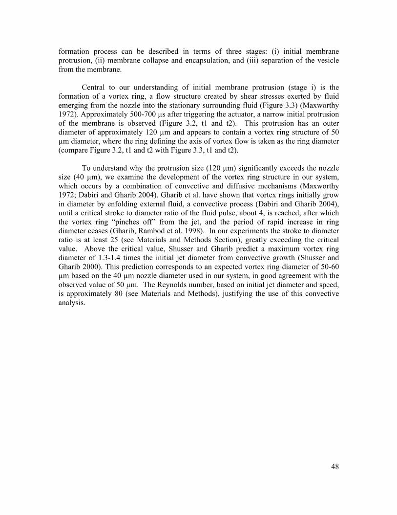
48
formation process can be described in terms of three stages: (i) initial membrane protrusion, (ii) membrane collapse and encapsulation, and (iii) separation of the vesicle from the membrane.
Central to our understanding of initial membrane protrusion (stage i) is the formation of a vortex ring, a flow structure created by shear stresses exerted by fluid emerging from the nozzle into the stationary surrounding fluid (Figure 3.3) (Maxworthy 1972). Approximately 500-700 µs after triggering the actuator, a narrow initial protrusion of the membrane is observed (Figure 3.2, t1 and t2). This protrusion has an outer diameter of approximately 120 µm and appears to contain a vortex ring structure of 50 µm diameter, where the ring defining the axis of vortex flow is taken as the ring diameter (compare Figure 3.2, t1 and t2 with Figure 3.3, t1 and t2).
To understand why the protrusion size (120 µm) significantly exceeds the nozzle size (40 µm), we examine the development of the vortex ring structure in our system, which occurs by a combination of convective and diffusive mechanisms (Maxworthy 1972; Dabiri and Gharib 2004). Gharib et al. have shown that vortex rings initially grow in diameter by enfolding external fluid, a convective process (Dabiri and Gharib 2004), until a critical stroke to diameter ratio of the fluid pulse, about 4, is reached, after which the vortex ring “pinches off” from the jet, and the period of rapid increase in ring diameter ceases (Gharib, Rambod et al. 1998). In our experiments the stroke to diameter ratio is at least 25 (see Materials and Methods Section), greatly exceeding the critical value. Above the critical value, Shusser and Gharib predict a maximum vortex ring diameter of 1.3-1.4 times the initial jet diameter from convective growth (Shusser and Gharib 2000). This prediction corresponds to an expected vortex ring diameter of 50-60 µm based on the 40 µm nozzle diameter used in our system, in good agreement with the observed value of 50 µm. The Reynolds number, based on initial jet diameter and speed, is approximately 80 (see Materials and Methods), justifying the use of this convective analysis.
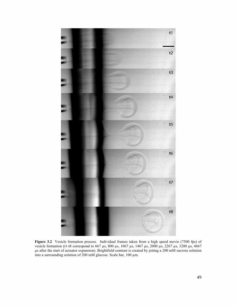
49
Figure 3.2 Vesicle formation process. Individual frames taken from a high speed movie (7500 fps) of vesicle formation (t1-t8 correspond to 667 µs, 800 µs, 1067 µs, 1467 µs, 2000 µs, 2267 µs, 3200 µs, 4667 µs after the start of actuator expansion). Brightfield contrast is created by jetting a 200 mM sucrose solution into a surrounding solution of 200 mM glucose. Scale bar, 100 µm.
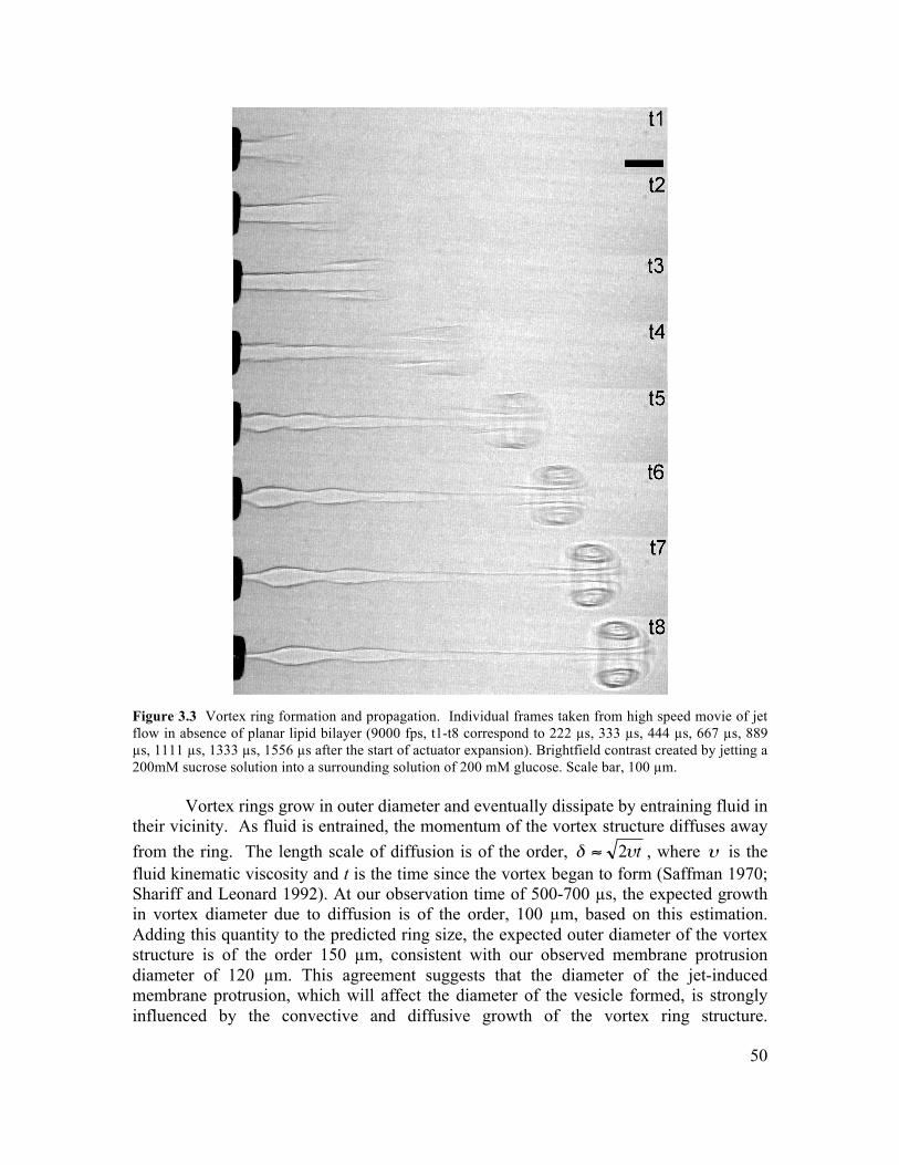
50
Figure 3.3 Vortex ring formation and propagation. Individual frames taken from high speed movie of jet flow in absence of planar lipid bilayer (9000 fps, t1-t8 correspond to 222 µs, 333 µs, 444 µs, 667 µs, 889 µs, 1111 µs, 1333 µs, 1556 µs after the start of actuator expansion). Brightfield contrast created by jetting a 200mM sucrose solution into a surrounding solution of 200 mM glucose. Scale bar, 100 µm.
Vortex rings grow in outer diameter and eventually dissipate by entraining fluid in their vicinity. As fluid is entrained, the momentum of the vortex structure diffuses away from the ring. The length scale of diffusion is of the order, tυδ 2≈ , where is the fluid kinematic viscosity and t is the time since the vortex began to form (Saffman 1970; Shariff and Leonard 1992). At our observation time of 500-700 µs, the expected growth in vortex diameter due to diffusion is of the order, 100 µm, based on this estimation. Adding this quantity to the predicted ring size, the expected outer diameter of the vortex structure is of the order 150 µm, consistent with our observed membrane protrusion diameter of 120 µm. This agreement suggests that the diameter of the jet-induced membrane protrusion, which will affect the diameter of the vesicle formed, is strongly influenced by the convective and diffusive growth of the vortex ring structure.
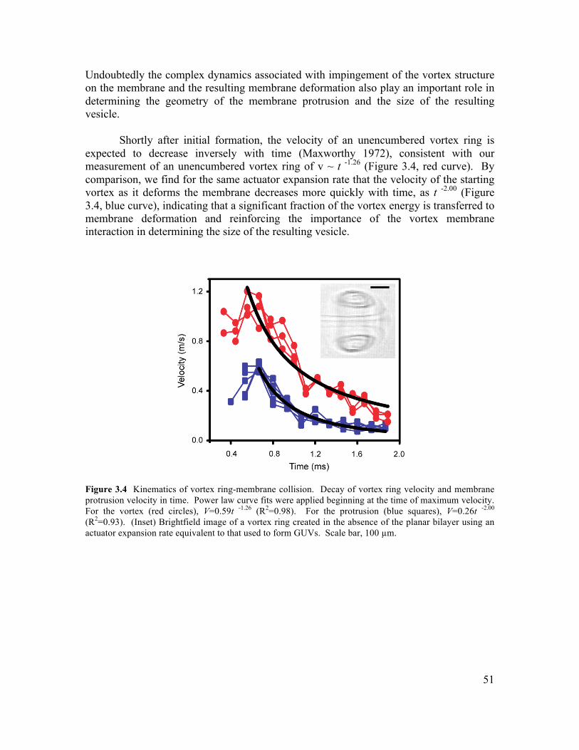
51
Undoubtedly the complex dynamics associated with impingement of the vortex structure on the membrane and the resulting membrane deformation also play an important role in determining the geometry of the membrane protrusion and the size of the resulting vesicle.
Shortly after initial formation, the velocity of an unencumbered vortex ring is expected to decrease inversely with time (Maxworthy 1972), consistent with our measurement of an unencumbered vortex ring of v ~ t -1.26 (Figure 3.4, red curve). By comparison, we find for the same actuator expansion rate that the velocity of the starting vortex as it deforms the membrane decreases more quickly with time, as t -2.00 (Figure 3.4, blue curve), indicating that a significant fraction of the vortex energy is transferred to membrane deformation and reinforcing the importance of the vortex membrane interaction in determining the size of the resulting vesicle.
Figure 3.4 Kinematics of vortex ring-membrane collision. Decay of vortex ring velocity and membrane protrusion velocity in time. Power law curve fits were applied beginning at the time of maximum velocity. For the vortex (red circles), V=0.59t -1.26 (R2=0.98). For the protrusion (blue squares), V=0.26t -2.00 (R2=0.93). (Inset) Brightfield image of a vortex ring created in the absence of the planar bilayer using an actuator expansion rate equivalent to that used to form GUVs. Scale bar, 100 µm.
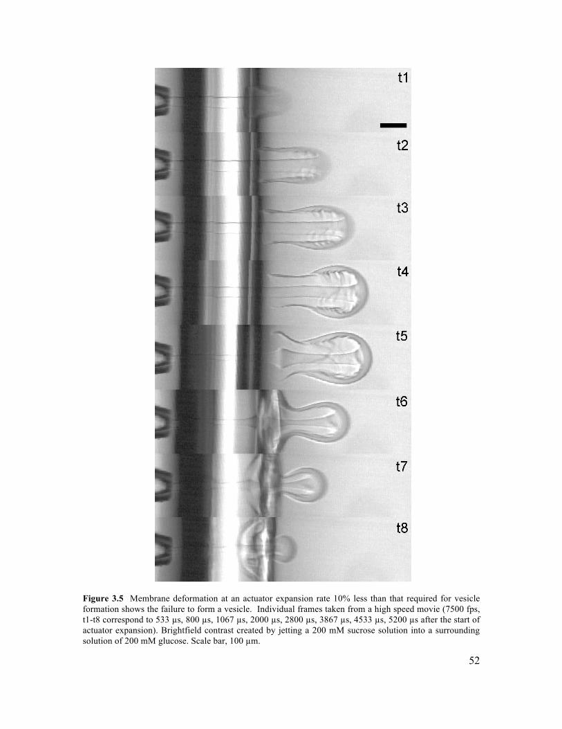
52
Figure 3.5 Membrane deformation at an actuator expansion rate 10% less than that required for vesicle formation shows the failure to form a vesicle. Individual frames taken from a high speed movie (7500 fps, t1-t8 correspond to 533 µs, 800 µs, 1067 µs, 2000 µs, 2800 µs, 3867 µs, 4533 µs, 5200 µs after the start of actuator expansion). Brightfield contrast created by jetting a 200 mM sucrose solution into a surrounding solution of 200 mM glucose. Scale bar, 100 µm.
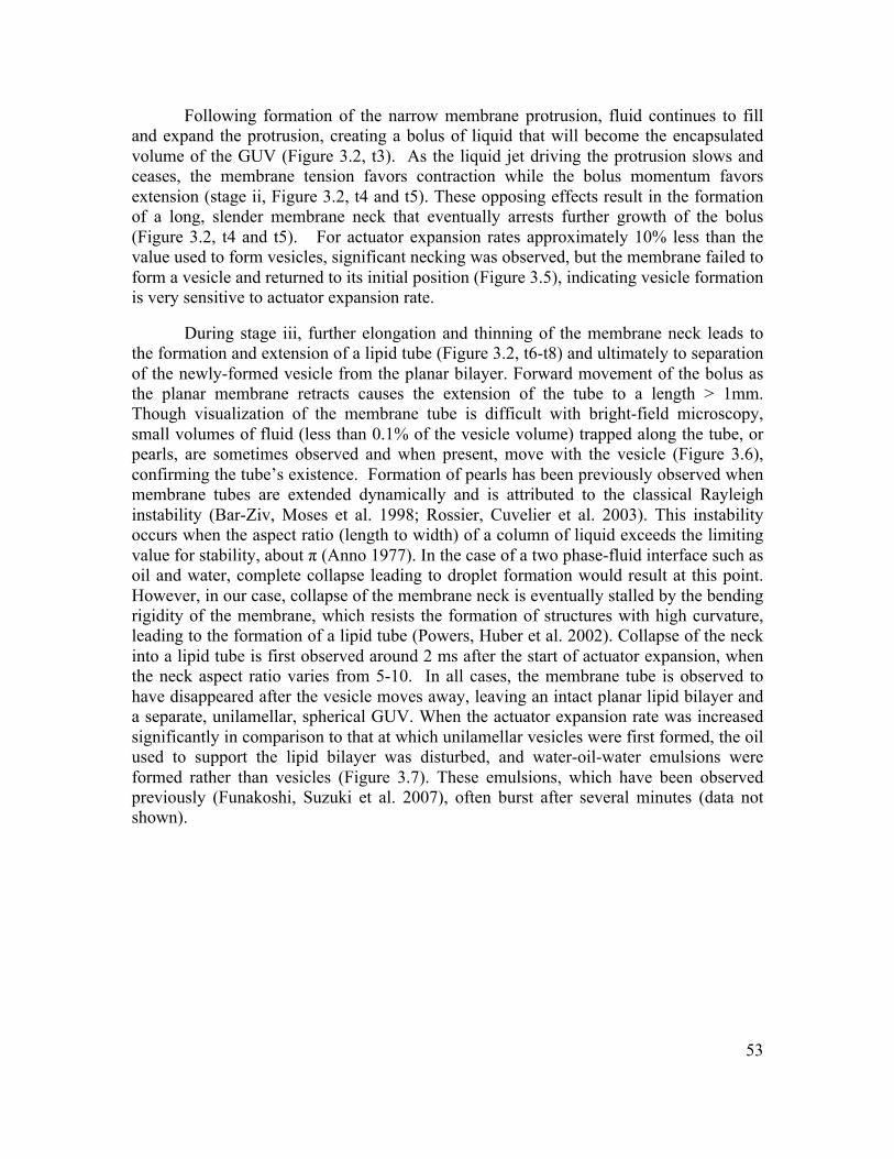
53
Following formation of the narrow membrane protrusion, fluid continues to fill and expand the protrusion, creating a bolus of liquid that will become the encapsulated volume of the GUV (Figure 3.2, t3). As the liquid jet driving the protrusion slows and ceases, the membrane tension favors contraction while the bolus momentum favors extension (stage ii, Figure 3.2, t4 and t5). These opposing effects result in the formation of a long, slender membrane neck that eventually arrests further growth of the bolus (Figure 3.2, t4 and t5). For actuator expansion rates approximately 10% less than the value used to form vesicles, significant necking was observed, but the membrane failed to form a vesicle and returned to its initial position (Figure 3.5), indicating vesicle formation is very sensitive to actuator expansion rate.
During stage iii, further elongation and thinning of the membrane neck leads to the formation and extension of a lipid tube (Figure 3.2, t6-t8) and ultimately to separation of the newly-formed vesicle from the planar bilayer. Forward movement of the bolus as the planar membrane retracts causes the extension of the tube to a length > 1mm. Though visualization of the membrane tube is difficult with bright-field microscopy, small volumes of fluid (less than 0.1% of the vesicle volume) trapped along the tube, or pearls, are sometimes observed and when present, move with the vesicle (Figure 3.6), confirming the tube’s existence. Formation of pearls has been previously observed when membrane tubes are extended dynamically and is attributed to the classical Rayleigh instability (Bar-Ziv, Moses et al. 1998; Rossier, Cuvelier et al. 2003). This instability occurs when the aspect ratio (length to width) of a column of liquid exceeds the limiting value for stability, about π (Anno 1977). In the case of a two phase-fluid interface such as oil and water, complete collapse leading to droplet formation would result at this point. However, in our case, collapse of the membrane neck is eventually stalled by the bending rigidity of the membrane, which resists the formation of structures with high curvature, leading to the formation of a lipid tube (Powers, Huber et al. 2002). Collapse of the neck into a lipid tube is first observed around 2 ms after the start of actuator expansion, when the neck aspect ratio varies from 5-10. In all cases, the membrane tube is observed to have disappeared after the vesicle moves away, leaving an intact planar lipid bilayer and a separate, unilamellar, spherical GUV. When the actuator expansion rate was increased significantly in comparison to that at which unilamellar vesicles were first formed, the oil used to support the lipid bilayer was disturbed, and water-oil-water emulsions were formed rather than vesicles (Figure 3.7). These emulsions, which have been observed previously (Funakoshi, Suzuki et al. 2007), often burst after several minutes (data not shown).
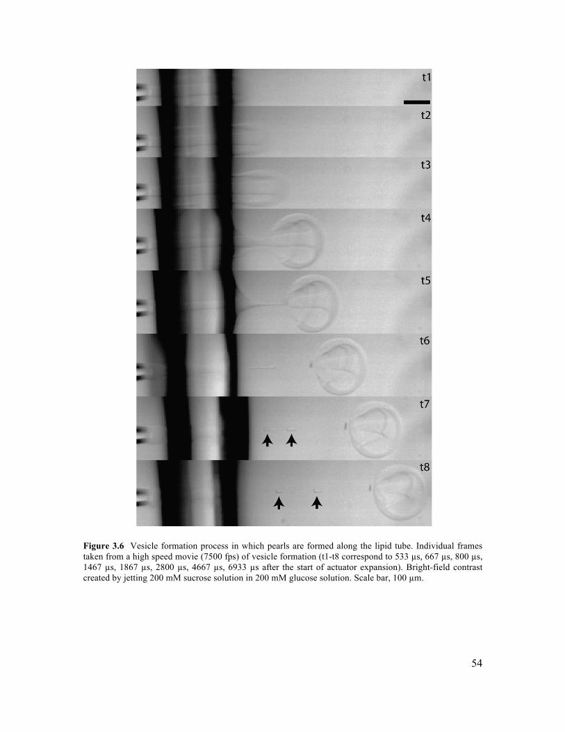
54
Figure 3.6 Vesicle formation process in which pearls are formed along the lipid tube. Individual frames taken from a high speed movie (7500 fps) of vesicle formation (t1-t8 correspond to 533 µs, 667 µs, 800 µs, 1467 µs, 1867 µs, 2800 µs, 4667 µs, 6933 µs after the start of actuator expansion). Bright-field contrast created by jetting 200 mM sucrose solution in 200 mM glucose solution. Scale bar, 100 µm.
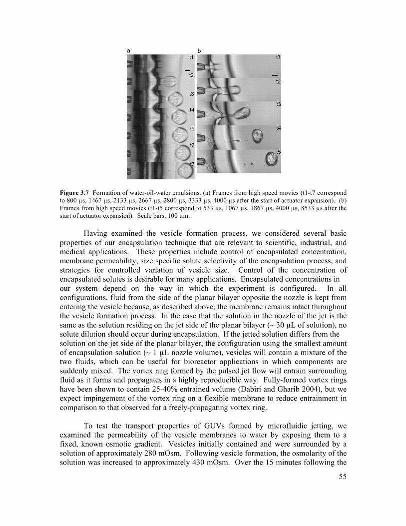
55
Figure 3.7 Formation of water-oil-water emulsions. (a) Frames from high speed movies (t1-t7 correspond to 800 µs, 1467 µs, 2133 µs, 2667 µs, 2800 µs, 3333 µs, 4000 µs after the start of actuator expansion). (b) Frames from high speed movies (t1-t5 correspond to 533 µs, 1067 µs, 1867 µs, 4000 µs, 8533 µs after the start of actuator expansion). Scale bars, 100 µm.
Having examined the vesicle formation process, we considered several basic properties of our encapsulation technique that are relevant to scientific, industrial, and medical applications. These properties include control of encapsulated concentration, membrane permeability, size specific solute selectivity of the encapsulation process, and strategies for controlled variation of vesicle size. Control of the concentration of encapsulated solutes is desirable for many applications. Encapsulated concentrations in our system depend on the way in which the experiment is configured. In all configurations, fluid from the side of the planar bilayer opposite the nozzle is kept from entering the vesicle because, as described above, the membrane remains intact throughout the vesicle formation process. In the case that the solution in the nozzle of the jet is the same as the solution residing on the jet side of the planar bilayer (~ 30 µL of solution), no solute dilution should occur during encapsulation. If the jetted solution differs from the solution on the jet side of the planar bilayer, the configuration using the smallest amount of encapsulation solution (~ 1 µL nozzle volume), vesicles will contain a mixture of the two fluids, which can be useful for bioreactor applications in which components are suddenly mixed. The vortex ring formed by the pulsed jet flow will entrain surrounding fluid as it forms and propagates in a highly reproducible way. Fully-formed vortex rings have been shown to contain 25-40% entrained volume (Dabiri and Gharib 2004), but we expect impingement of the vortex ring on a flexible membrane to reduce entrainment in comparison to that observed for a freely-propagating vortex ring.
To test the transport properties of GUVs formed by microfluidic jetting, we examined the permeability of the vesicle membranes to water by exposing them to a fixed, known osmotic gradient. Vesicles initially contained and were surrounded by a solution of approximately 280 mOsm. Following vesicle formation, the osmolarity of the solution was increased to approximately 430 mOsm. Over the 15 minutes following the
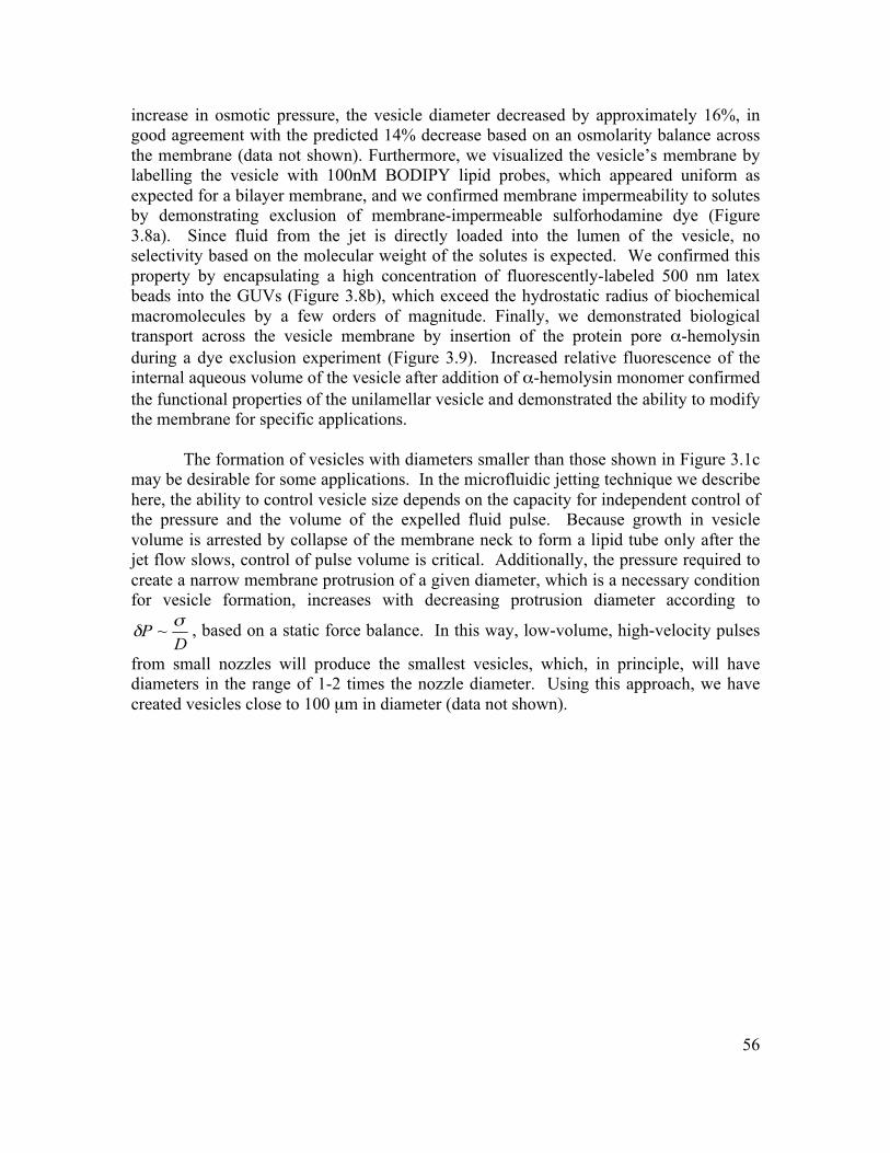
56
increase in osmotic pressure, the vesicle diameter decreased by approximately 16%, in good agreement with the predicted 14% decrease based on an osmolarity balance across the membrane (data not shown). Furthermore, we visualized the vesicle’s membrane by labelling the vesicle with 100nM BODIPY lipid probes, which appeared uniform as expected for a bilayer membrane, and we confirmed membrane impermeability to solutes by demonstrating exclusion of membrane-impermeable sulforhodamine dye (Figure 3.8a). Since fluid from the jet is directly loaded into the lumen of the vesicle, no selectivity based on the molecular weight of the solutes is expected. We confirmed this property by encapsulating a high concentration of fluorescently-labeled 500 nm latex beads into the GUVs (Figure 3.8b), which exceed the hydrostatic radius of biochemical macromolecules by a few orders of magnitude. Finally, we demonstrated biological transport across the vesicle membrane by insertion of the protein pore α-hemolysin during a dye exclusion experiment (Figure 3.9). Increased relative fluorescence of the internal aqueous volume of the vesicle after addition of α-hemolysin monomer confirmed the functional properties of the unilamellar vesicle and demonstrated the ability to modify the membrane for specific applications.
The formation of vesicles with diameters smaller than those shown in Figure 3.1c may be desirable for some applications. In the microfluidic jetting technique we describe here, the ability to control vesicle size depends on the capacity for independent control of the pressure and the volume of the expelled fluid pulse. Because growth in vesicle volume is arrested by collapse of the membrane neck to form a lipid tube only after the jet flow slows, control of pulse volume is critical. Additionally, the pressure required to create a narrow membrane protrusion of a given diameter, which is a necessary condition for vesicle formation, increases with decreasing protrusion diameter according to
, based on a static force balance. In this way, low-volume, high-velocity pulses
from small nozzles will produce the smallest vesicles, which, in principle, will have diameters in the range of 1-2 times the nozzle diameter. Using this approach, we have created vesicles close to 100 µm in diameter (data not shown).
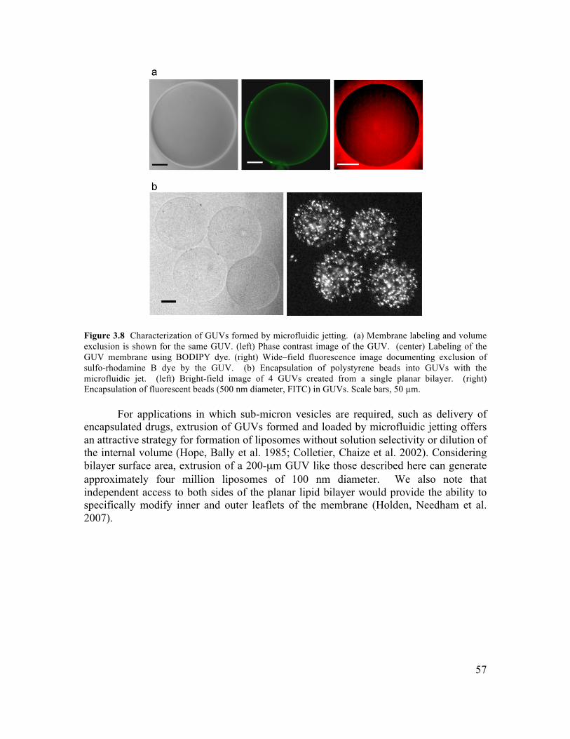
57
Figure 3.8 Characterization of GUVs formed by microfluidic jetting. (a) Membrane labeling and volume exclusion is shown for the same GUV. (left) Phase contrast image of the GUV. (center) Labeling of the GUV membrane using BODIPY dye. (right) Wide–field fluorescence image documenting exclusion of sulfo-rhodamine B dye by the GUV. (b) Encapsulation of polystyrene beads into GUVs with the microfluidic jet. (left) Bright-field image of 4 GUVs created from a single planar bilayer. (right) Encapsulation of fluorescent beads (500 nm diameter, FITC) in GUVs. Scale bars, 50 µm.
For applications in which sub-micron vesicles are required, such as delivery of encapsulated drugs, extrusion of GUVs formed and loaded by microfluidic jetting offers an attractive strategy for formation of liposomes without solution selectivity or dilution of the internal volume (Hope, Bally et al. 1985; Colletier, Chaize et al. 2002). Considering bilayer surface area, extrusion of a 200-µm GUV like those described here can generate approximately four million liposomes of 100 nm diameter. We also note that independent access to both sides of the planar lipid bilayer would provide the ability to specifically modify inner and outer leaflets of the membrane (Holden, Needham et al. 2007).
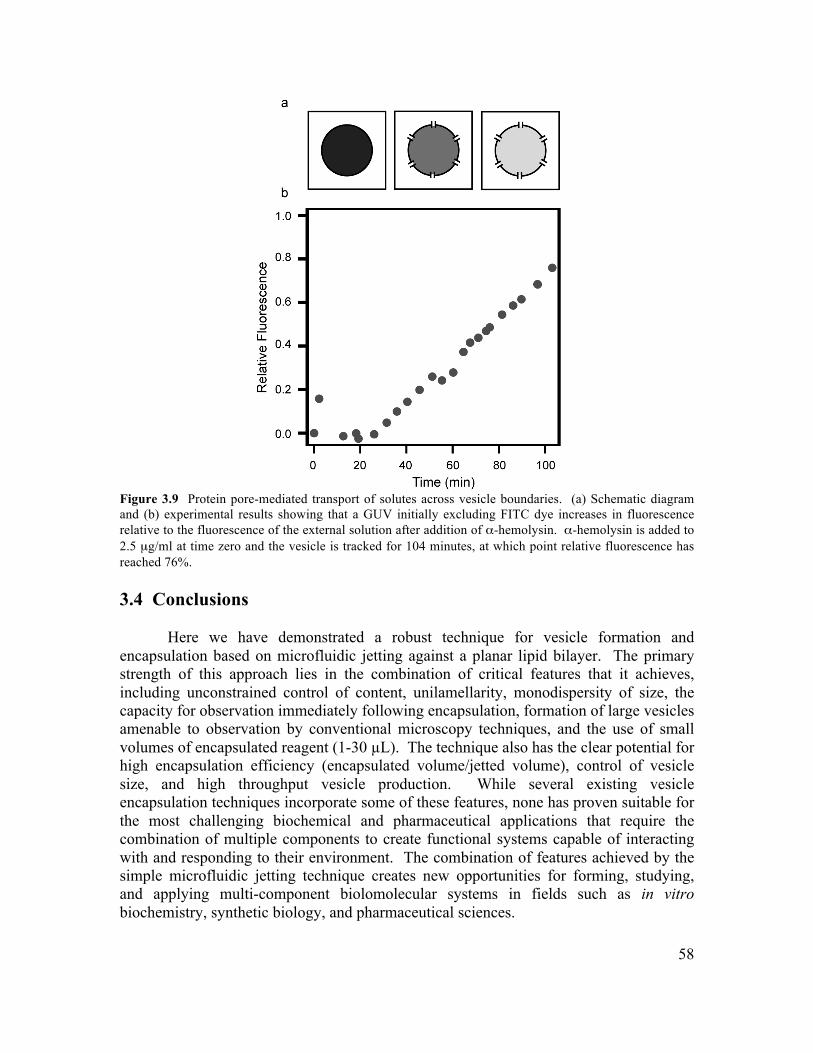
58
Figure 3.9 Protein pore-mediated transport of solutes across vesicle boundaries. (a) Schematic diagram and (b) experimental results showing that a GUV initially excluding FITC dye increases in fluorescence relative to the fluorescence of the external solution after addition of α-hemolysin. α-hemolysin is added to 2.5 µg/ml at time zero and the vesicle is tracked for 104 minutes, at which point relative fluorescence has reached 76%. 3.4 Conclusions
Here we have demonstrated a robust technique for vesicle formation and encapsulation based on microfluidic jetting against a planar lipid bilayer. The primary strength of this approach lies in the combination of critical features that it achieves, including unconstrained control of content, unilamellarity, monodispersity of size, the capacity for observation immediately following encapsulation, formation of large vesicles amenable to observation by conventional microscopy techniques, and the use of small volumes of encapsulated reagent (1-30 µL). The technique also has the clear potential for high encapsulation efficiency (encapsulated volume/jetted volume), control of vesicle size, and high throughput vesicle production. While several existing vesicle encapsulation techniques incorporate some of these features, none has proven suitable for the most challenging biochemical and pharmaceutical applications that require the combination of multiple components to create functional systems capable of interacting with and responding to their environment. The combination of features achieved by the simple microfluidic jetting technique creates new opportunities for forming, studying, and applying multi-component biolomolecular systems in fields such as in vitro biochemistry, synthetic biology, and pharmaceutical sciences.
59
3.5 Materials and Methods 3.5.1 Solutions Used in the Jet Device
Sucrose and glucose were dissolved in deionized water to achieve the desired concentration and osmolality. Each solution was passed through a 0.2 µm filter. In the experiments to demonstrate encapsulation of particles, polychromatic red latex microsphere solution (0.5 µm diameter, 2.63% solids, Polysciences, Inc., Warrington, PA) was added in a volume ratio of 3:1000 after filtration. 3.5.2 Planar Bilayer Formation
Planar lipid bilayers were formed by contacting monolayers as described by Funakoshi et al. (Funakoshi, Suzuki et al. 2006; Funakoshi, Suzuki et al. 2007). Bilayer formation took place in a home-built transparent acrylic chamber. The chamber was constructed by laser-cutting an “infinity” shape out of a 3-mm-thick sheet of acrylic (TAP Plastics, Dublin, CA) (Figure 3.1a,b), where the “waist” of the pattern was about 1.5 - 2 mm wide. A hole of approximately 1.4 mm diameter was drilled in one end of the chamber to facilitate insertion of the glass micro-nozzle. The chamber was then bonded to a flat, 2 mm thick, acrylic substrate using acrylic cement (TAP plastics, Dublin, CA). The chamber assembly was allowed to set for at least 8 hours at room temperature before use. 1,2-Diphytanoyl-sn-Glycero-3-Phosphocholine (DPhPC, Avanti Polar Lipids) was the lipid used to form the planar bilayers, though the technique need not be specific to this lipid. The lipid was dried under rough vacuum in a test tube for approximately 90 minutes, leaving a dry lipid film on the test tube walls. After vacuum treatment, the lipid was resuspended in n-decane (Sigma Aldrich) at 25 mg/mL. Following addition of n-decane, the solution was stored at - 20 C with drierite (W.A. Hammond Drierite Co. Ltd., Xenia, OH). To prepare the planar bilayer, 12-14 µL of the lipid/decane solution was injected into the bottom of the chamber. Water droplets, 27-30 µL in volume, were injected into each side of the chamber sequentially. After formation, the bilayer was allowed to equilibrate for approximately 1 minute before insertion of the glass micro-nozzle. 3.5.3 Vesicle Characterization
Vesicles formed by microfluidic jetting were fluorescently labeled with BODIPY 500/510 C8, C5 (Molecular Probes, Inc) and tested for exclusion of membrane-impermeable Sulforhodamine B (Sigma Aldrich). To test for functional insertion of a trans-membrane protein, we tested incorporation of α-hemolysin into a vesicle. 10 µM FITC dye (Molecular Probes, Inc) was added to the solution surrounding a vesicle formed by microfluidic jetting, and wide field fluorescence imaging confirmed exclusion of the dye from the vesicle’s internal volume. Next, α-hemolysin monomers (Sigma Aldrich) were added to the solution surrounding the vesicle to a final concentration of 2.5 µg/ml, and the average fluorescence over a fixed area of the vesicle’s internal volume and a fixed area of the external solution were monitored for 104 minutes. Relative fluorescence
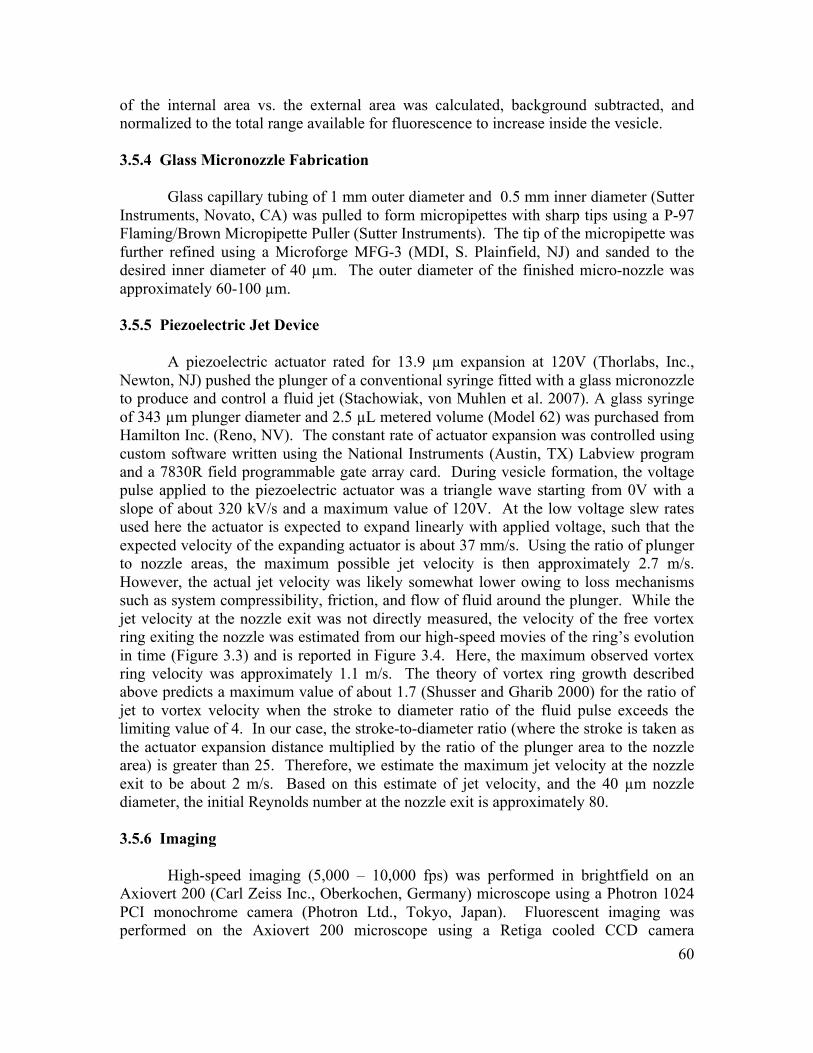
60
of the internal area vs. the external area was calculated, background subtracted, and normalized to the total range available for fluorescence to increase inside the vesicle. 3.5.4 Glass Micronozzle Fabrication
Glass capillary tubing of 1 mm outer diameter and 0.5 mm inner diameter (Sutter Instruments, Novato, CA) was pulled to form micropipettes with sharp tips using a P-97 Flaming/Brown Micropipette Puller (Sutter Instruments). The tip of the micropipette was further refined using a Microforge MFG-3 (MDI, S. Plainfield, NJ) and sanded to the desired inner diameter of 40 µm. The outer diameter of the finished micro-nozzle was approximately 60-100 µm. 3.5.5 Piezoelectric Jet Device
A piezoelectric actuator rated for 13.9 µm expansion at 120V (Thorlabs, Inc., Newton, NJ) pushed the plunger of a conventional syringe fitted with a glass micronozzle to produce and control a fluid jet (Stachowiak, von Muhlen et al. 2007). A glass syringe of 343 µm plunger diameter and 2.5 µL metered volume (Model 62) was purchased from Hamilton Inc. (Reno, NV). The constant rate of actuator expansion was controlled using custom software written using the National Instruments (Austin, TX) Labview program and a 7830R field programmable gate array card. During vesicle formation, the voltage pulse applied to the piezoelectric actuator was a triangle wave starting from 0V with a slope of about 320 kV/s and a maximum value of 120V. At the low voltage slew rates used here the actuator is expected to expand linearly with applied voltage, such that the expected velocity of the expanding actuator is about 37 mm/s. Using the ratio of plunger to nozzle areas, the maximum possible jet velocity is then approximately 2.7 m/s. However, the actual jet velocity was likely somewhat lower owing to loss mechanisms such as system compressibility, friction, and flow of fluid around the plunger. While the jet velocity at the nozzle exit was not directly measured, the velocity of the free vortex ring exiting the nozzle was estimated from our high-speed movies of the ring’s evolution in time (Figure 3.3) and is reported in Figure 3.4. Here, the maximum observed vortex ring velocity was approximately 1.1 m/s. The theory of vortex ring growth described above predicts a maximum value of about 1.7 (Shusser and Gharib 2000) for the ratio of jet to vortex velocity when the stroke to diameter ratio of the fluid pulse exceeds the limiting value of 4. In our case, the stroke-to-diameter ratio (where the stroke is taken as the actuator expansion distance multiplied by the ratio of the plunger area to the nozzle area) is greater than 25. Therefore, we estimate the maximum jet velocity at the nozzle exit to be about 2 m/s. Based on this estimate of jet velocity, and the 40 µm nozzle diameter, the initial Reynolds number at the nozzle exit is approximately 80. 3.5.6 Imaging
High-speed imaging (5,000 – 10,000 fps) was performed in brightfield on an Axiovert 200 (Carl Zeiss Inc., Oberkochen, Germany) microscope using a Photron 1024 PCI monochrome camera (Photron Ltd., Tokyo, Japan). Fluorescent imaging was performed on the Axiovert 200 microscope using a Retiga cooled CCD camera
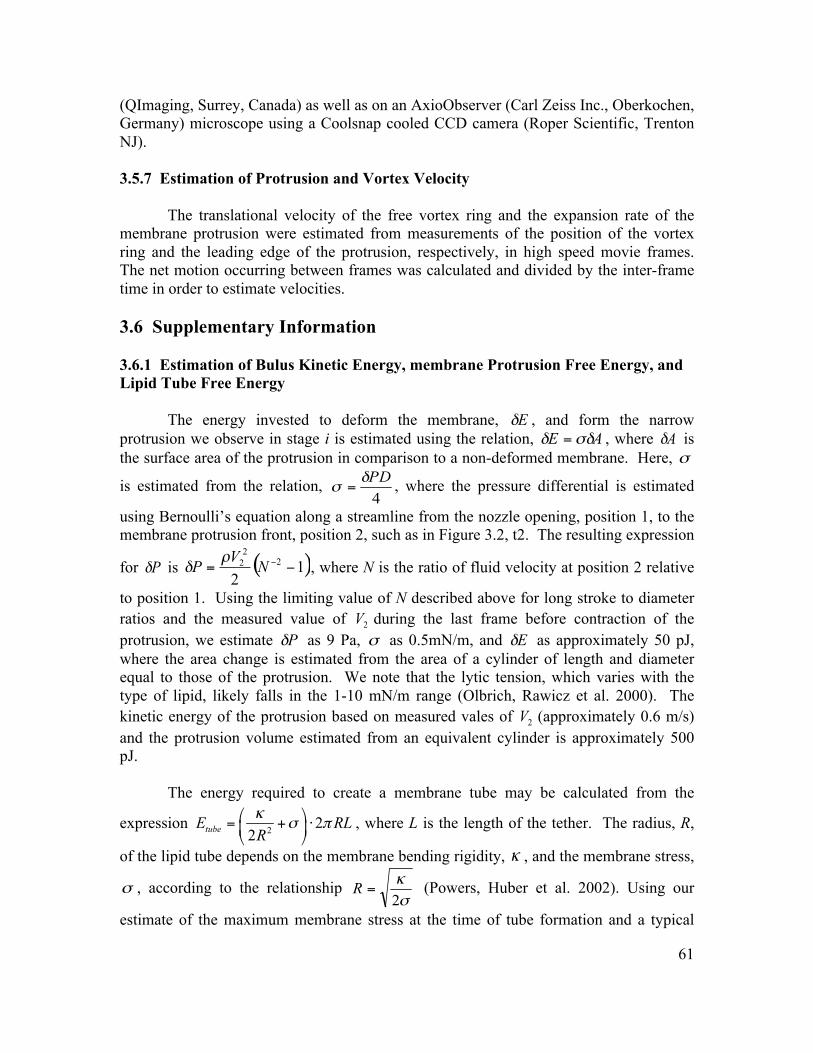
61
(QImaging, Surrey, Canada) as well as on an AxioObserver (Carl Zeiss Inc., Oberkochen, Germany) microscope using a Coolsnap cooled CCD camera (Roper Scientific, Trenton NJ). 3.5.7 Estimation of Protrusion and Vortex Velocity
The translational velocity of the free vortex ring and the expansion rate of the membrane protrusion were estimated from measurements of the position of the vortex ring and the leading edge of the protrusion, respectively, in high speed movie frames. The net motion occurring between frames was calculated and divided by the inter-frame time in order to estimate velocities. 3.6 Supplementary Information 3.6.1 Estimation of Bulus Kinetic Energy, membrane Protrusion Free Energy, and Lipid Tube Free Energy
The energy invested to deform the membrane, , and form the narrow protrusion we observe in stage i is estimated using the relation, , where is the surface area of the protrusion in comparison to a non-deformed membrane. Here,
is estimated from the relation, , where the pressure differential is estimated
using Bernoulli’s equation along a streamline from the nozzle opening, position 1, to the membrane protrusion front, position 2, such as in Figure 3.2, t2. The resulting expression
for is ( )12
222 −= −NVP ρ
δ , where N is the ratio of fluid velocity at position 2 relative
to position 1. Using the limiting value of N described above for long stroke to diameter ratios and the measured value of during the last frame before contraction of the protrusion, we estimate as 9 Pa, as 0.5mN/m, and as approximately 50 pJ, where the area change is estimated from the area of a cylinder of length and diameter equal to those of the protrusion. We note that the lytic tension, which varies with the type of lipid, likely falls in the 1-10 mN/m range (Olbrich, Rawicz et al. 2000). The kinetic energy of the protrusion based on measured vales of (approximately 0.6 m/s) and the protrusion volume estimated from an equivalent cylinder is approximately 500 pJ.
The energy required to create a membrane tube may be calculated from the
expression , where L is the length of the tether. The radius, R,
of the lipid tube depends on the membrane bending rigidity, , and the membrane stress,
, according to the relationship (Powers, Huber et al. 2002). Using our
estimate of the maximum membrane stress at the time of tube formation and a typical
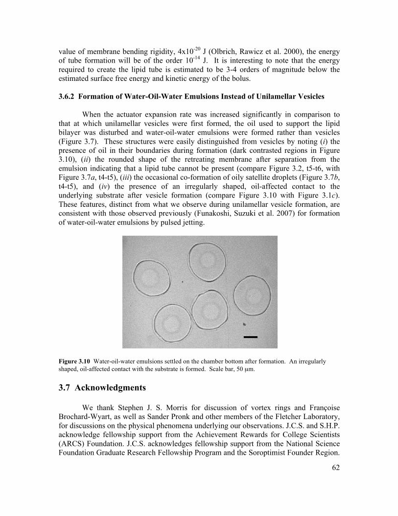
62
value of membrane bending rigidity, 4x10-20 J (Olbrich, Rawicz et al. 2000), the energy of tube formation will be of the order 10-14 J. It is interesting to note that the energy required to create the lipid tube is estimated to be 3-4 orders of magnitude below the estimated surface free energy and kinetic energy of the bolus. 3.6.2 Formation of Water-Oil-Water Emulsions Instead of Unilamellar Vesicles
When the actuator expansion rate was increased significantly in comparison to that at which unilamellar vesicles were first formed, the oil used to support the lipid bilayer was disturbed and water-oil-water emulsions were formed rather than vesicles (Figure 3.7). These structures were easily distinguished from vesicles by noting (i) the presence of oil in their boundaries during formation (dark contrasted regions in Figure 3.10), (ii) the rounded shape of the retreating membrane after separation from the emulsion indicating that a lipid tube cannot be present (compare Figure 3.2, t5-t6, with Figure 3.7a, t4-t5), (iii) the occasional co-formation of oily satellite droplets (Figure 3.7b, t4-t5), and (iv) the presence of an irregularly shaped, oil-affected contact to the underlying substrate after vesicle formation (compare Figure 3.10 with Figure 3.1c). These features, distinct from what we observe during unilamellar vesicle formation, are consistent with those observed previously (Funakoshi, Suzuki et al. 2007) for formation of water-oil-water emulsions by pulsed jetting.
Figure 3.10 Water-oil-water emulsions settled on the chamber bottom after formation. An irregularly shaped, oil-affected contact with the substrate is formed. Scale bar, 50 µm. 3.7 Acknowledgments
We thank Stephen J. S. Morris for discussion of vortex rings and Françoise Brochard-Wyart, as well as Sander Pronk and other members of the Fletcher Laboratory, for discussions on the physical phenomena underlying our observations. J.C.S. and S.H.P. acknowledge fellowship support from the Achievement Rewards for College Scientists (ARCS) Foundation. J.C.S. acknowledges fellowship support from the National Science Foundation Graduate Research Fellowship Program and the Soroptimist Founder Region.

63
D.L.R. and A.P.L. acknowledge fellowship support from the Natural Sciences and Engineering Research Council of Canada. This work was supported by a National Institutes of Health Nanomedicine Development Centers award (to D.A.F.).
64
Chapter 4: Inkjet Formation of Unilamellar Lipid Vesicles for Cell-like Encapsulation
Reproduced by permission of The Royal Society of Chemistry. Jeanne C. Stachowiak, David L. Richmond, Thomas H. Li, Françoise Brochard-Wyart,
and Daniel A. Fletcher (2009). “Inkjet Formation of Unilamellar Lipid Vesicles for Cell-like Encapsulation.” Lab on a Chip 9(14): 2003-2009.
http://pubs.rsc.org/en/Content/ArticleLanding/2009/LC/B904984C
© 2009 by The Royal Society of Chemistry
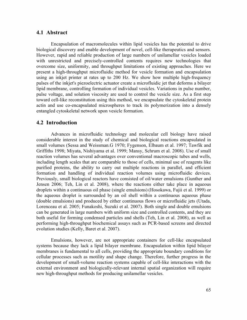
65
4.1 Abstract
Encapsulation of macromolecules within lipid vesicles has the potential to drive biological discovery and enable development of novel, cell-like therapeutics and sensors. However, rapid and reliable production of large numbers of unilamellar vesicles loaded with unrestricted and precisely-controlled contents requires new technologies that overcome size, uniformity, and throughput limitations of existing approaches. Here we present a high-throughput microfluidic method for vesicle formation and encapsulation using an inkjet printer at rates up to 200 Hz. We show how multiple high-frequency pulses of the inkjet's piezoelectric actuator create a microfluidic jet that deforms a bilayer lipid membrane, controlling formation of individual vesicles. Variations in pulse number, pulse voltage, and solution viscosity are used to control the vesicle size. As a first step toward cell-like reconstitution using this method, we encapsulate the cytoskeletal protein actin and use co-encapsulated microspheres to track its polymerization into a densely entangled cytoskeletal network upon vesicle formation. 4.2 Introduction
Advances in microfluidic technology and molecular cell biology have raised considerable interest in the study of chemical and biological reactions encapsulated in small volumes (Sessa and Weissman.G 1970; Fygenson, Elbaum et al. 1997; Tawfik and Griffiths 1998; Miyata, Nishiyama et al. 1999; Mansy, Schrum et al. 2008). Use of small reaction volumes has several advantages over conventional macroscopic tubes and wells, including length scales that are comparable to those of cells, minimal use of reagents like purified proteins, the ability to carry out multiple reactions in parallel, and efficient formation and handling of individual reaction volumes using microfluidic devices. Previously, small biological reactors have consisted of oil/water emulsions (Gunther and Jensen 2006; Teh, Lin et al. 2008), where the reactions either take place in aqueous droplets within a continuous oil phase (single emulsions) (Hosokawa, Fujii et al. 1999) or the aqueous droplet is surrounded by an oil shell within a continuous aqueous phase (double emulsions) and produced by either continuous flows or microfluidic jets (Utada, Lorenceau et al. 2005; Funakoshi, Suzuki et al. 2007). Both single and double emulsions can be generated in large numbers with uniform size and controlled contents, and they are both useful for forming condensed particles and shells (Teh, Lin et al. 2008), as well as performing high-throughput biochemical assays such as PCR-based screens and directed evolution studies (Kelly, Baret et al. 2007).
Emulsions, however, are not appropriate containers for cell-like encapsulated systems because they lack a lipid bilayer membrane. Encapsulation within lipid bilayer membranes is fundamental to all cells, providing the appropriate boundary conditions for cellular processes such as motility and shape change. Therefore, further progress in the development of small-volume reaction systems capable of cell-like interactions with the external environment and biologically-relevant internal spatial organization will require new high-throughput methods for producing unilamellar vesicles.
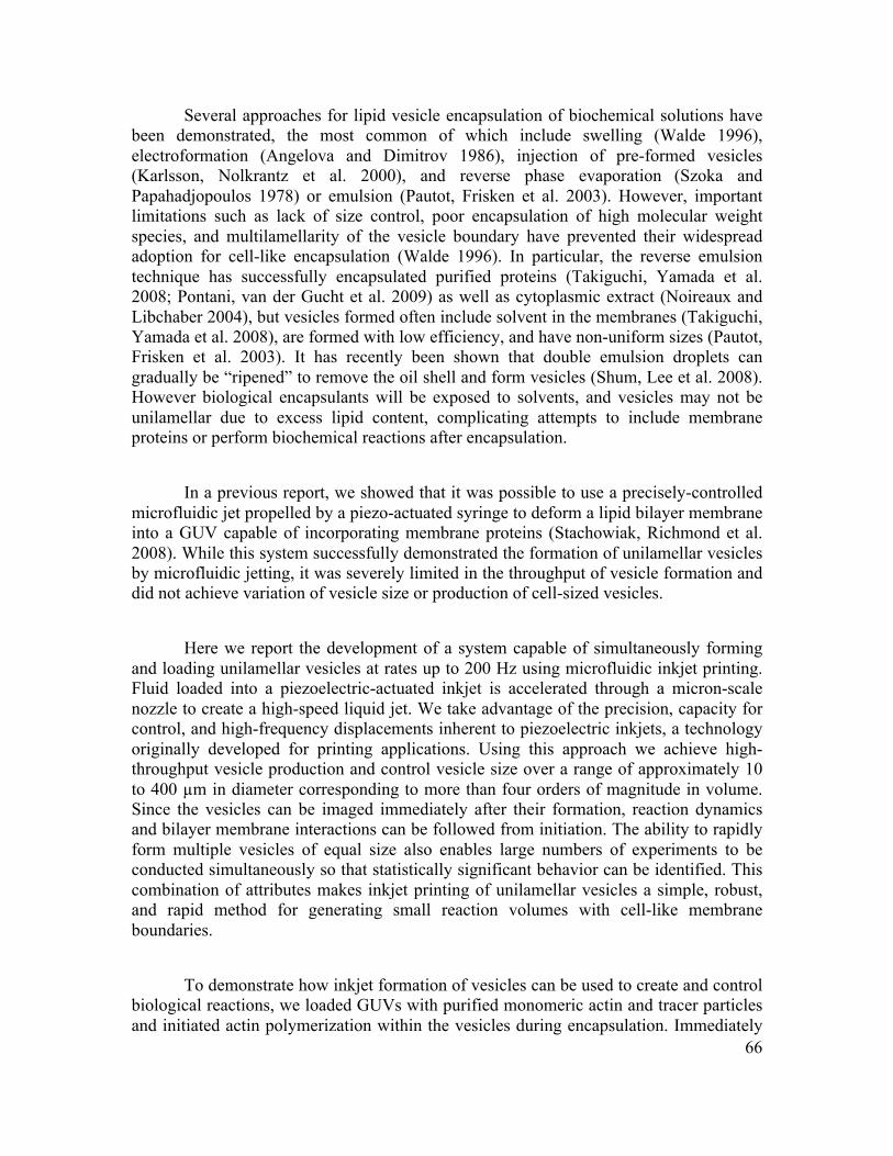
66
Several approaches for lipid vesicle encapsulation of biochemical solutions have been demonstrated, the most common of which include swelling (Walde 1996), electroformation (Angelova and Dimitrov 1986), injection of pre-formed vesicles (Karlsson, Nolkrantz et al. 2000), and reverse phase evaporation (Szoka and Papahadjopoulos 1978) or emulsion (Pautot, Frisken et al. 2003). However, important limitations such as lack of size control, poor encapsulation of high molecular weight species, and multilamellarity of the vesicle boundary have prevented their widespread adoption for cell-like encapsulation (Walde 1996). In particular, the reverse emulsion technique has successfully encapsulated purified proteins (Takiguchi, Yamada et al. 2008; Pontani, van der Gucht et al. 2009) as well as cytoplasmic extract (Noireaux and Libchaber 2004), but vesicles formed often include solvent in the membranes (Takiguchi, Yamada et al. 2008), are formed with low efficiency, and have non-uniform sizes (Pautot, Frisken et al. 2003). It has recently been shown that double emulsion droplets can gradually be “ripened” to remove the oil shell and form vesicles (Shum, Lee et al. 2008). However biological encapsulants will be exposed to solvents, and vesicles may not be unilamellar due to excess lipid content, complicating attempts to include membrane proteins or perform biochemical reactions after encapsulation.
In a previous report, we showed that it was possible to use a precisely-controlled microfluidic jet propelled by a piezo-actuated syringe to deform a lipid bilayer membrane into a GUV capable of incorporating membrane proteins (Stachowiak, Richmond et al. 2008). While this system successfully demonstrated the formation of unilamellar vesicles by microfluidic jetting, it was severely limited in the throughput of vesicle formation and did not achieve variation of vesicle size or production of cell-sized vesicles.
Here we report the development of a system capable of simultaneously forming and loading unilamellar vesicles at rates up to 200 Hz using microfluidic inkjet printing. Fluid loaded into a piezoelectric-actuated inkjet is accelerated through a micron-scale nozzle to create a high-speed liquid jet. We take advantage of the precision, capacity for control, and high-frequency displacements inherent to piezoelectric inkjets, a technology originally developed for printing applications. Using this approach we achieve high-throughput vesicle production and control vesicle size over a range of approximately 10 to 400 µm in diameter corresponding to more than four orders of magnitude in volume. Since the vesicles can be imaged immediately after their formation, reaction dynamics and bilayer membrane interactions can be followed from initiation. The ability to rapidly form multiple vesicles of equal size also enables large numbers of experiments to be conducted simultaneously so that statistically significant behavior can be identified. This combination of attributes makes inkjet printing of unilamellar vesicles a simple, robust, and rapid method for generating small reaction volumes with cell-like membrane boundaries.
To demonstrate how inkjet formation of vesicles can be used to create and control biological reactions, we loaded GUVs with purified monomeric actin and tracer particles and initiated actin polymerization within the vesicles during encapsulation. Immediately
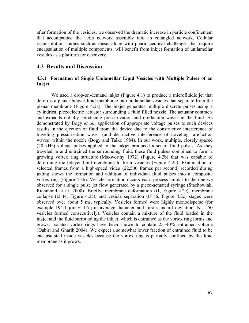
67
after formation of the vesicles, we observed the dramatic increase in particle confinement that accompanied the actin network assembly into an entangled network. Cellular reconstitution studies such as these, along with pharmaceutical challenges that require encapsulation of multiple components, will benefit from inkjet formation of unilamellar vesicles as a platform for discovery. 4.3 Results and Discussion 4.3.1 Formation of Single Unilamellar Lipid Vesicles with Multiple Pulses of an Inkjet
We used a drop-on-demand inkjet (Figure 4.1) to produce a microfluidic jet that deforms a planar bilayer lipid membrane into unilamellar vesicles that separate from the planar membrane (Figure 4.2a). The inkjet generates multiple discrete pulses using a cylindrical piezoelectric actuator surrounding a fluid filled nozzle. The actuator contracts and expands radially, producing pressurization and rarefaction waves in the fluid. As demonstrated by Bogy et al., application of appropriate voltage pulses to such devices results in the ejection of fluid from the device due to the constructive interference of traveling pressurization waves (and destructive interference of traveling rarefaction waves) within the nozzle (Bogy and Talke 1984). In our work, multiple, closely spaced (20 kHz) voltage pulses applied to the inkjet produced a set of fluid pulses. As they traveled in and entrained the surrounding fluid, these fluid pulses combined to form a growing vortex ring structure (Maxworthy 1972) (Figure 4.2b) that was capable of deforming the bilayer lipid membrane to form vesicles (Figure 4.2c). Examination of selected frames from a high-speed video (22,500 frames per second) recorded during jetting shows the formation and addition of individual fluid pulses into a composite vortex ring (Figure 4.2b). Vesicle formation occurs via a process similar to the one we observed for a single pulse jet flow generated by a piezo-actuated syringe (Stachowiak, Richmond et al. 2008). Briefly, membrane deformation (t1, Figure 4.2c), membrane collapse (t2–t4, Figure 4.2c), and vesicle separation (t5–t6, Figure 4.2c) stages were observed over about 5 ms, typically. Vesicles formed were highly monodisperse (for example 194.1 µm ± 4.6 µm average diameter and first standard deviation, N = 50 vesicles formed consecutively). Vesicles contain a mixture of the fluid loaded in the inkjet and the fluid surrounding the inkjet, which is entrained as the vortex ring forms and grows. Isolated vortex rings have been shown to contain 25–40% entrained volume (Dabiri and Gharib 2004). We expect a somewhat lower fraction of entrained fluid to be encapsulated inside vesicles because the vortex ring is partially confined by the lipid membrane as it grows.
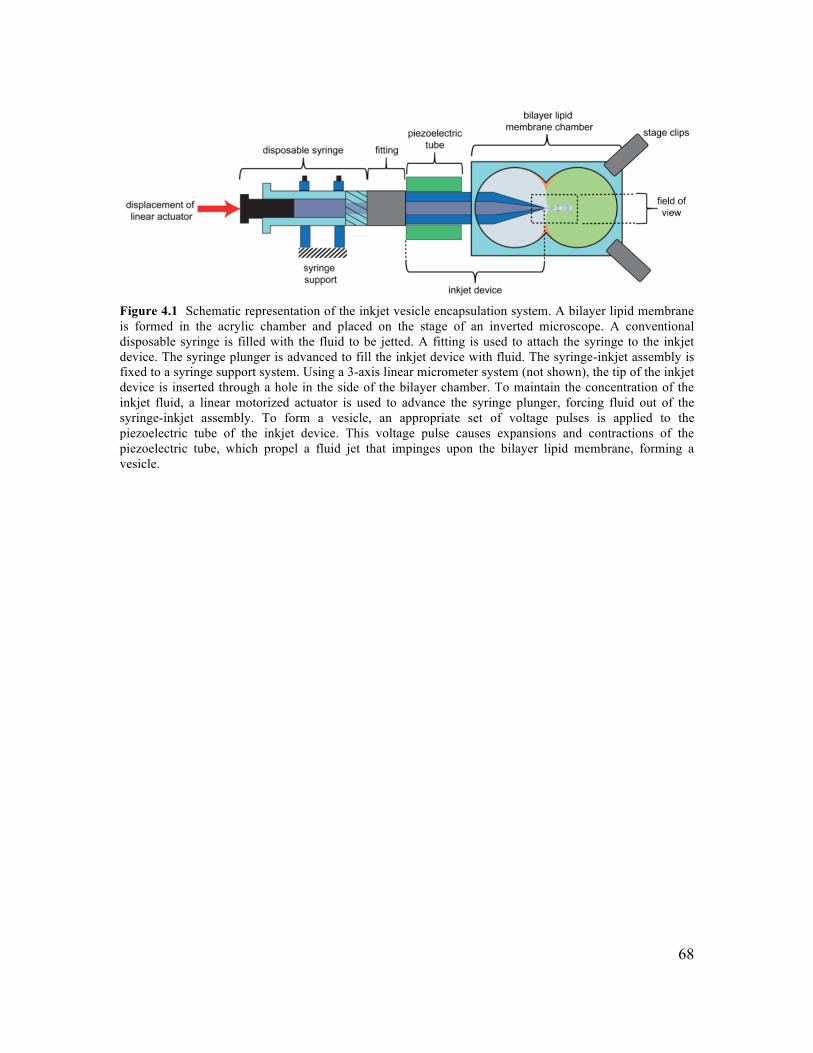
68
Figure 4.1 Schematic representation of the inkjet vesicle encapsulation system. A bilayer lipid membrane is formed in the acrylic chamber and placed on the stage of an inverted microscope. A conventional disposable syringe is filled with the fluid to be jetted. A fitting is used to attach the syringe to the inkjet device. The syringe plunger is advanced to fill the inkjet device with fluid. The syringe-inkjet assembly is fixed to a syringe support system. Using a 3-axis linear micrometer system (not shown), the tip of the inkjet device is inserted through a hole in the side of the bilayer chamber. To maintain the concentration of the inkjet fluid, a linear motorized actuator is used to advance the syringe plunger, forcing fluid out of the syringe-inkjet assembly. To form a vesicle, an appropriate set of voltage pulses is applied to the piezoelectric tube of the inkjet device. This voltage pulse causes expansions and contractions of the piezoelectric tube, which propel a fluid jet that impinges upon the bilayer lipid membrane, forming a vesicle.
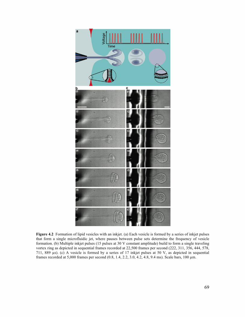
69
Figure 4.2 Formation of lipid vesicles with an inkjet. (a) Each vesicle is formed by a series of inkjet pulses that form a single microfluidic jet, where pauses between pulse sets determine the frequency of vesicle formation. (b) Multiple inkjet pulses (15 pulses at 30 V constant amplitude) build to form a single traveling vortex ring as depicted in sequential frames recorded at 22,500 frames per second (222, 311, 356, 444, 578, 711, 889 µs). (c) A vesicle is formed by a series of 17 inkjet pulses at 50 V, as depicted in sequential frames recorded at 5,000 frames per second (0.8, 1.4, 2.2, 3.0, 4.2, 4.8, 9.4 ms). Scale bars, 100 µm.
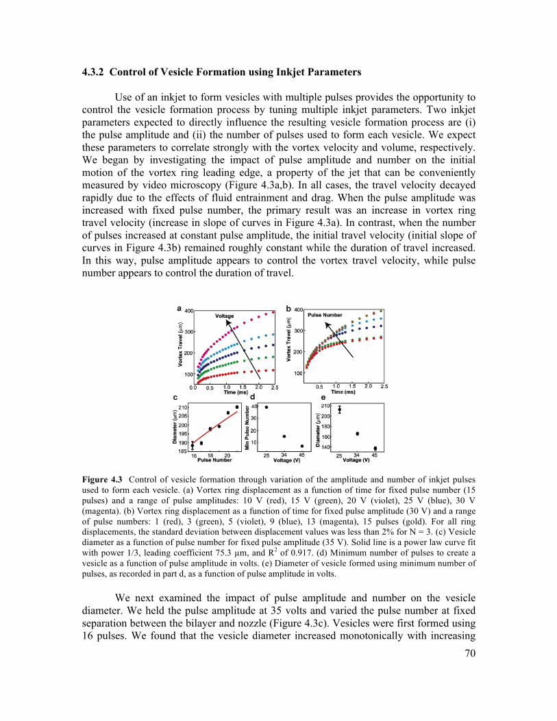
70
4.3.2 Control of Vesicle Formation using Inkjet Parameters
Use of an inkjet to form vesicles with multiple pulses provides the opportunity to control the vesicle formation process by tuning multiple inkjet parameters. Two inkjet parameters expected to directly influence the resulting vesicle formation process are (i) the pulse amplitude and (ii) the number of pulses used to form each vesicle. We expect these parameters to correlate strongly with the vortex velocity and volume, respectively. We began by investigating the impact of pulse amplitude and number on the initial motion of the vortex ring leading edge, a property of the jet that can be conveniently measured by video microscopy (Figure 4.3a,b). In all cases, the travel velocity decayed rapidly due to the effects of fluid entrainment and drag. When the pulse amplitude was increased with fixed pulse number, the primary result was an increase in vortex ring travel velocity (increase in slope of curves in Figure 4.3a). In contrast, when the number of pulses increased at constant pulse amplitude, the initial travel velocity (initial slope of curves in Figure 4.3b) remained roughly constant while the duration of travel increased. In this way, pulse amplitude appears to control the vortex travel velocity, while pulse number appears to control the duration of travel.
Figure 4.3 Control of vesicle formation through variation of the amplitude and number of inkjet pulses used to form each vesicle. (a) Vortex ring displacement as a function of time for fixed pulse number (15 pulses) and a range of pulse amplitudes: 10 V (red), 15 V (green), 20 V (violet), 25 V (blue), 30 V (magenta). (b) Vortex ring displacement as a function of time for fixed pulse amplitude (30 V) and a range of pulse numbers: 1 (red), 3 (green), 5 (violet), 9 (blue), 13 (magenta), 15 pulses (gold). For all ring displacements, the standard deviation between displacement values was less than 2% for N = 3. (c) Vesicle diameter as a function of pulse number for fixed pulse amplitude (35 V). Solid line is a power law curve fit with power 1/3, leading coefficient 75.3 µm, and R2 of 0.917. (d) Minimum number of pulses to create a vesicle as a function of pulse amplitude in volts. (e) Diameter of vesicle formed using minimum number of pulses, as recorded in part d, as a function of pulse amplitude in volts.
We next examined the impact of pulse amplitude and number on the vesicle diameter. We held the pulse amplitude at 35 volts and varied the pulse number at fixed separation between the bilayer and nozzle (Figure 4.3c). Vesicles were first formed using 16 pulses. We found that the vesicle diameter increased monotonically with increasing
71
number of pulses from approximately 187 µm (16 pulses) to 210 µm (21 pulses). The relationship between pulse number and vesicle diameter was fit reasonably well (R2 = 0.917, N = 18) by a power law relation with exponent 1/3, as would be expected if the vesicle volume varied proportionally with pulse number. However, the ideal fit (R2 = 0.965) was achieved with a somewhat larger exponent (0.429 ± 0.04) indicating that vesicle volume increased with pulse number faster than could be accounted for by a linear relationship. This additional growth likely arose from fluid entrainment, which had more time to evolve as the pulse number increased, increasing the duration of the composite pulse. We examined the combined impact of variations in pulse number and amplitude on vesicle diameter, identifying the minimum number of pulses needed to create a vesicle, 7–39, over a range of pulse amplitudes, 25–45 volts (Figure 4.3d). We found that the minimum number of pulses decreased with increasing pulse amplitude, and the vesicle diameter decreased with increasing pulse amplitude (Figure 4.3e) from approximately 210 to 140 µm. Here as pulse velocity increased with increasing amplitude, the amount of membrane deformation achieved by each pulse increased such that fewer pulses were needed to form a vesicle, and the resulting vesicle was smaller. 4.3.3 Formation of Cell-Sized Vesicles through Variation of Fluid Viscosity
Some experiments using small encapsulated volumes, particularly those aimed at reconstituting specific cellular processes, would benefit from vesicle dimensions on the scale of typical single cells. Vesicle diameters in the range of 1–50 µm would better emulate most eukaryotic and some bacterial cells, extending the range of encapsulation applications. Since vesicle volume is defined during the encapsulation process by collapse of the deformed membrane around the jetted fluid, we hypothesized that differences in viscosity on either side of the bilayer membrane would alter the collapse dynamics and resulting vesicle size.
First, we found that jetting of a more viscous solution (8.75 w/v% ficoll 400 and
300 mM sucrose dissolved in water ~ 5 cp) while maintaining an inviscid solution on both sides of the bilayer (300 mM glucose dissolved in water ~1 cp) led to a dramatic increase in vesicle diameter (380 µm diameter, data not shown).
Next, we investigated whether jetting a less viscous fluid into a more viscous fluid would lead to the formation of a smaller vesicle. The fluid in the jet (300 mM sucrose solution) and on the jet side of the bilayer (300 mM glucose solution) had a viscosity of approximately 1 cp, while the viscosity of the fluid on the opposing side of the bilayer had approximately 3.9 cp viscosity (7.5 w/v% ficoll 400 and 300 mM glucose solution) at low shear rates as measured by rheometry (Figure 4.4a). We observed that vesicles of significantly smaller size (approximately 8–110 µm) were formed in this configuration (Figure 4.4b). Notably, vesicles were formed during retraction of the membrane rather than during expansion, and the process of formation was characterized by an asymmetric retraction, not observed in the absence of a viscosity differential. Specifically, lateral retraction of the membrane sides occurred more rapidly than axial retraction of the membrane, such that the aspect ratio (axial extent to lateral extent) of the membrane protrusion increased during retraction until a vesicle was formed.
72
Vesicle formation is successful when the lateral retraction of membrane sides comes to completion before the axial retraction of the membrane, allowing a portion of the membrane area to separate. The observered decrease in vesicle size with increase in viscosity differential is expected considering that each membrane retraction process, axial and lateral, depends on viscosity. Axial retraction involves dragging the vesicle bolus through the surrounding fluid and is therefore slowed down by increasing the viscosity of the fluid on the side of the bilayer opposite the jet. Lateral retraction requires expulsion of the encapsulated fluid through the bolus neck and is thus sped up by decreasing the viscosity of the fluid on the jet side of the bilayer (in and around the jet). Therefore, when a relatively higher viscosity solution is used in the jet, the rate of axial retraction increases relative to the rate of lateral retraction such that longer, more powerful ejections are required to form vesicles, and the resulting vesicles are larger. In contrast, use of a lower viscosity in the jet than on the opposing side of the membrane decreases the rate of axial retraction in comparison to lateral retraction, resulting in an asymmetric contraction of the membrane that enables formation of smaller vesicles. Cell-sized vesicles formed using this viscosity differential were monodisperse with a typical variation in diameter of approximately 10% within populations made using the same jetting parameters (relative viscosity, voltage, pulse number, and nozzle-bilayer separation). It is likely that these parameters can be varied in order to maintain a specific vesicle size while accommodating variations in the composition and viscosity of encapsulated solution. However, interdependencies between these parameters have not been characterized quantitatively.
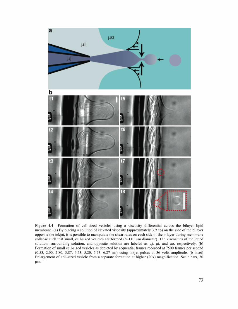
73
Figure 4.4 Formation of cell-sized vesicles using a viscosity differential across the bilayer lipid membrane. (a) By placing a solution of elevated viscosity (approximately 3.9 cp) on the side of the bilayer opposite the inkjet, it is possible to manipulate the shear rates on each side of the bilayer during membrane collapse such that small, cell-sized vesicles are formed (8–110 µm diameter). The viscosities of the jetted solution, surrounding solution, and opposite solution are labeled as µj, µi, and µo, respectively. (b) Formation of small cell-sized vesicles as depicted by sequential frames recorded at 7500 frames per second (0.53, 2.00, 2.80, 3.87, 4.53, 5.20, 5.73, 6.27 ms) using inkjet pulses at 36 volts amplitude. (b inset) Enlargement of cell-sized vesicle from a separate formation at higher (20x) magnification. Scale bars, 50 µm.
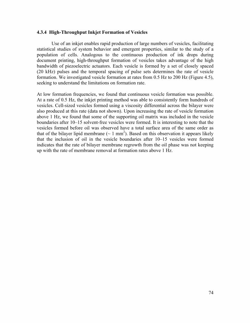
74
4.3.4 High-Throughput Inkjet Formation of Vesicles
Use of an inkjet enables rapid production of large numbers of vesicles, facilitating statistical studies of system behavior and emergent properties, similar to the study of a population of cells. Analogous to the continuous production of ink drops during document printing, high-throughput formation of vesicles takes advantage of the high bandwidth of piezoelectric actuators. Each vesicle is formed by a set of closely spaced (20 kHz) pulses and the temporal spacing of pulse sets determines the rate of vesicle formation. We investigated vesicle formation at rates from 0.5 Hz to 200 Hz (Figure 4.5), seeking to understand the limitations on formation rate.
At low formation frequencies, we found that continuous vesicle formation was possible. At a rate of 0.5 Hz, the inkjet printing method was able to consistently form hundreds of vesicles. Cell-sized vesicles formed using a viscosity differential across the bilayer were also produced at this rate (data not shown). Upon increasing the rate of vesicle formation above 1 Hz, we found that some of the supporting oil matrix was included in the vesicle boundaries after 10–15 solvent-free vesicles were formed. It is interesting to note that the vesicles formed before oil was observed have a total surface area of the same order as that of the bilayer lipid membrane (~ 1 mm2). Based on this observation it appears likely that the inclusion of oil in the vesicle boundaries after 10–15 vesicles were formed indicates that the rate of bilayer membrane regrowth from the oil phase was not keeping up with the rate of membrane removal at formation rates above 1 Hz.
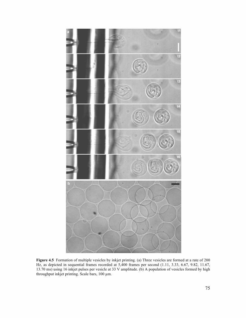
75
Figure 4.5 Formation of multiple vesicles by inkjet printing. (a) Three vesicles are formed at a rate of 200 Hz, as depicted in sequential frames recorded at 5,400 frames per second (1.11, 3.33, 6.67, 9.82, 11.67, 13.70 ms) using 16 inkjet pulses per vesicle at 33 V amplitude. (b) A population of vesicles formed by high throughput inkjet printing. Scale bars, 100 µm.
76
At higher frequencies, multiple solvent-free vesicles could still be formed, though oil fouled the vesicles after only a few (less than 15) were made. When small batches of vesicles are formed, the rate of membrane regrowth no longer limits the vesicle production rate. Instead, the formation rate should be limited by the time required for a single vesicle to form and the lipid membrane to relax back to its original position, which is about 5 ms. In agreement with this idea, we were able to form several solvent-free vesicles at rates up to 200 Hz (Figure 4.5a). After several vesicles are formed at this rate, a pause in vesicle formation of 2–4 seconds allows the bilayer to regrow. In this way, multiple batches of several solvent-free vesicles each were formed with an inter-batch spacing of 2–4 seconds and an inter-vesicle spacing of as little as 5 ms (200 Hz). This maximum rate of vesicle formation may be particularly useful if the rate of membrane regrowth can be increased such that it is no longer limiting, and it therefore likely represents an upper limit for vesicle production rates.
4.3.5 Real-Time Assembly and Interrogation of Actin Networks Inside Vesicles
Encapsulation of biological molecules with defined composition and concentration is a significant technical challenge that has limited progress on reconstituting cellular processes in vitro. To demonstrate the utility of vesicle formation and loading by inkjet printing for reconstitution experiments, we loaded and polymerized the cytoskeletal protein actin in the lumen of a GUV (Figure 4.6). A bilayer lipid membrane was set up with actin polymerization buffer on each side. Purified actin and latex beads (used to probe solution rheology) were loaded into the inkjet nozzle in monomeric form, and a vesicle containing a mixture of actin monomers (~ 0.39 mg/mL monomeric actin), beads, and polymerization buffer was formed (Figure 4.6a). Entrainment of actin polymerization buffer during vesicle formation initiated actin polymerization only in the lumen of the GUV, avoiding clogging the inkjet nozzle and temporally defining the start of the reaction such that actin polymerization could be observed immediately following encapsulation.
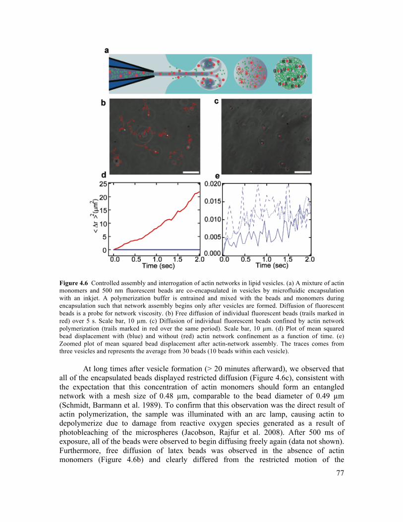
77
Figure 4.6 Controlled assembly and interrogation of actin networks in lipid vesicles. (a) A mixture of actin monomers and 500 nm fluorescent beads are co-encapsulated in vesicles by microfluidic encapsulation with an inkjet. A polymerization buffer is entrained and mixed with the beads and monomers during encapsulation such that network assembly begins only after vesicles are formed. Diffusion of fluorescent beads is a probe for network viscosity. (b) Free diffusion of individual fluorescent beads (trails marked in red) over 5 s. Scale bar, 10 µm. (c) Diffusion of individual fluorescent beads confined by actin network polymerization (trails marked in red over the same period). Scale bar, 10 µm. (d) Plot of mean squared bead displacement with (blue) and without (red) actin network confinement as a function of time. (e) Zoomed plot of mean squared bead displacement after actin-network assembly. The traces comes from three vesicles and represents the average from 30 beads (10 beads within each vesicle).
At long times after vesicle formation (> 20 minutes afterward), we observed that all of the encapsulated beads displayed restricted diffusion (Figure 4.6c), consistent with the expectation that this concentration of actin monomers should form an entangled network with a mesh size of 0.48 µm, comparable to the bead diameter of 0.49 µm (Schmidt, Barmann et al. 1989). To confirm that this observation was the direct result of actin polymerization, the sample was illuminated with an arc lamp, causing actin to depolymerize due to damage from reactive oxygen species generated as a result of photobleaching of the microspheres (Jacobson, Rajfur et al. 2008). After 500 ms of exposure, all of the beads were observed to begin diffusing freely again (data not shown). Furthermore, free diffusion of latex beads was observed in the absence of actin monomers (Figure 4.6b) and clearly differed from the restricted motion of the
78
encapsulated beads (Figure 4.6d,e). Specifically, the slope of the mean squared displacement versus time curve for freely diffusing beads (Figure 4.6d, red) is more than 3 orders of magnitude larger than the slope of the curve for vesicle encapsulated beads restricted by entangled actin filaments (Figure 4.6d,e blue).
This experiment demonstrates the ability of microfluidic vesicle formation to perform controlled encapsulation of active protein solutions and initiate biomolecular reactions inside lipid vesicles. Further, controlled encapsulation and polymerization of actin within a unilamellar lipid vesicle is an important step toward reconstitution of the cytoskeleton and its membrane interactions. Reconstitution of cytoskeletal structures on lipid vesicles has emerged as a powerful approach for investigating the interplay between force generating polymer networks and deformable lipid membrane substrates (Liu, Richmond et al. 2008; Osawa, Anderson et al. 2008). While cortical actin networks have recently been assembled in the lumen of GUVs (Pontani, van der Gucht et al. 2009), reconstitution of complex membrane bound cytoskeletal structures has been limited by the challenge of encapsulating known ratios of actin, actin binding proteins and membrane bound crosslinkers and nucleation factors. Direct control of vesicle size and content by microfluidic encapsulation with an inkjet offers a new platform for quantitatively investigating how specific proteins influence the architecture of membrane bound cytoskeletal and related questions in the emerging area of cellular reconstitution. 4.4 Conclusions
New experimental techniques are needed to enable the assembly of lipid vesicle encapsulated systems with increasing sophistication and similarity to living systems. In this paper, we demonstrate a high-throughput microfluidic encapsulation method using an inkjet for unilamellar vesicle formation and loading, which enables the unrestricted encapsulation of biological macromolecules and synthetic particles. We show that uniformly sized vesicles can be produced at rates up to 200 Hz, enabling studies on large populations of confined bioreactors. Further, through manipulation of inkjet parameters and fluid viscosity, we show that vesicles size can be controlled over a wide range (fewer than 10 µm to greater than 400 µm in diameter), which encompasses the size of many cells, a capability that will enable in vitro reconstitution of cellular structures and processes.
As a demonstration of in vitro reconstitution within inkjet-formed vesicles, we polymerized actin monomers upon encapsulation with 500 nm latex beads in the lumen of a unilamellar vesicle. This study exploits an inherent feature of our technique, reproducible mixing between the droplet volume and the jetted volume, to deliver the polymerization initiators during vesicle formation and to provide a passive readout of the mechanical properties of the actin network by bead diffusion. Further, this approach can be generalized to initiate many other reactions at the time of vesicle formation.
By facilitating further development of cell-like encapsulated systems, inkjet-based vesicle production will provide new opportunities for fundamental understanding of biological processes and advancement of primitive cell studies (Noireaux and Libchaber
79
2004; Mansy, Schrum et al. 2008). Additionally, the capacity of vesicle encapsulated systems to incorporate components and processes borrowed from biological cells will promote the design of increasingly sophisticated cell-like assays (Kelly, Baret et al. 2007) and drug delivery tools (LaVan, McGuire et al. 2003).
4.5 Materials and Methods 4.5.1 Reagents
1,2-Diphytanoyl-sn-glycero-3-phosphocholine (DPhPC) lipid was purchased dissolved in chloroform from Avanti Polar Lipids, resuspended in n-decane (Sigma-Aldrich) at a concentration of 25 mg/ml, and stored at −20 °C with a dessicant (Drierite). Sucrose and glucose were prepared at approximately 400 mOsm. Ficoll PM 400 (Amersham Biosciences) solutions was prepared at 7.5–8.75 weight percent, and 300 mM of glucose was added to aid in visualization during jetting. Actin was purified from rabbit muscle acetone powder (Spudich and Watt 1971), and purity was confirmed by sodium dodecyl sulfate polyacrylamide gel electrophoresis. Actin concentration was determined by UV absorbance and BCA assays. 4.5.2 Rheometry
Viscosity of solutions was measured at low shear rates (18–50 s−1) using a Gemini rheometer (Malvern Instruments) with a concentric cylinder geometry. 4.5.3 Inkjet Device and Vesicle Formation
Inkjets and drive electronics were from MicroFab Technologies. Inkjets used home built glass orifices installed by MicroFab. Orifices were made from glass capillary stock (0.6 mm inner diameter and 0.75 mm outer diameter) and formed by pulling the capillaries into micropipettes with sharp tips (P97 Flaming/Brown Micropipette Puller, Sutter Instruments). Micropipettes were refined using a Microforge MFG-3 (MicroData Instruments) and sanded to the desired orifice inner diameter, 10 µm. Disposable syringes were used to load inkjets with the jetted solution from the rear and provided constant perfusion of this solution (approximately 10 µL/min) during experiments. Loaded inkjets were inserted into bilayer lipid membrane chambers and positioned with less than 200 µm between the nozzle orifice and bilayer (Figure 4.1). Multiple fluid pulses from the print head (12–30) were used to form vesicles. Application of a trapezoidal voltage pulse from the drive triggered each pulse. Identical pulses repeated at 20 kHz had a rise time of 3 µs, amplitude of 25–35 V, duration at this amplitude of 35 µs (to maximize velocity), and fall time of 3 µs. Vesicle formation was recorded using high-speed microscopy (500–30,000 frames per second, Photron 1024 PCI). Osmotically balanced (~ 400 mOsM) solutions of sucrose in the nozzle and glucose surrounding the bilayer were used to achieve optical contrast and sinking of the vesicles to the chamber bottom for observation.
80
4.5.4 Planar Bilayer Lipid Membranes
Vesicles were formed from planar lipid bilayer membranes constructed by contacting monolayers in a double-well chamber (Funakoshi, Suzuki et al. 2006; Holden, Needham et al. 2007; Stachowiak, Richmond et al. 2008). Bilayers were formed at the intersection of chamber wells (30–80 µL each), where chambers had the shape of an “infinity” symbol, and the bilayer was formed at the waist of the pattern. However, chamber wells of arbitrary shape are possible, where circular, ellipsoidal, and rectangular shapes have been used. Chambers were made using a laser cutter (Versa Laser) typically from 3 mm acrylic sheets (TAP plastics) and bonded to acrylic cover slips (0.2 mm thick, Astra Products) using acrylic cement (TAP plastics). A hole of approximately 1.5 mm diameter was drilled on one end of the chamber, perpendicular to the bilayer plane, to facilitate insertion and positioning of the inkjet nozzle. Adhesive (Locktite 495) adhered a thin (0.26 mm) sheet of natural rubber (McMaster-Carr) to the external surface of this hole to provide a seal. A needle was used to make a small hole in the rubber sheet for insertion of the inkjet nozzle. To form bilayer lipid membranes, approximately 12 µL of lipid solution (25 mg/mL DPhPC dissolved in n-decane) was pipetted into the chamber. Aqueous droplets were pipetted sequentially into each of the fluid chambers and rapidly came into contact, forming the bilayer lipid membrane at their interface. 4.5.5 Actin Network Polymerization
To polymerize 9.2 µM actin in the lumen of GUVs (assuming 50% dilution during encapsulation), the inkjet was loaded with 385 mOsm sucrose, 5 mM Tris HCl pH 7.8, 0.2 mM CaCl2, 0.01% NaN3, 2 mM ATP pH 7.5, 18.4 µM actin, and 300x dilution of 2.63% solids-latex Fluoresbrite Polychromatic red 0.5 µm diameter microspheres (Polysciences, Inc.). Microspheres were sonicated for 5 minutes prior to use in order to break up aggregates. The solution was filtered prior to addition of the microspheres, ATP, and actin. The solution in the droplets surrounding the bilayer lipid membrane contained 200 mM KCl, 4 mM MgCl2, and 2 mM EGTA pH 7.5. The vesicles were formed at 22 volts and 18 pulses, and bead motion was monitored between 15 and 40 minutes from the time of encapsulation. For the control experiment used to assess microsphere diffusion in the absence of an actin network, solutions A and B were prepared. Solution A contained 385 mOsm sucrose, 5 mM Tris HCl pH 7.8, 0.2 mM CaCl2, 0.01% NaN3, 333x dilution of sonicated 2.63% solids-latex Fluoresbrite Polychromatic red 0.5 micron microspheres. Solution B contained 200 mM KCl, 4 mM MgCl2, 2 mM EGTA pH 7.5. Solutions A and B were mixed in a 1:1 ratio and added to a homemade chamber (0.1 mm × 5 mm × 20 mm) consisting of a glass coverslip adhered to a glass slide using double-sided tape, then sealed with VALAP (1:1:1 of vaseline, lanoline, and paraffin) before imaging. Bead diffusion was recorded at 100x using a CoolSnap HQ Camera (Photometrics). Bead tracking was done using the Track Points application in Metamorph v7.1 (Molecular Devices), and diffusion curves were calculated using MatLab software (MathWorks).
81
4.6 Acknowledgments
The authors are grateful to Malvern Instruments for use of the Gemini rheometer and C.S. Dutcher of the Muller lab for assistance with viscosity measurements. D.L.R. acknowledges fellowship support from the Natural Sciences and Engineering Research Council of Canada. This work was supported by the Cell Propulsion Lab, a National Institutes of Health Nanomedicine Development Center at UC Berkeley and UCSF (to D.A.F.). Sandia is a multiprogram laboratory operated by Sandia Corporation, a Lockheed Martin Company, for the United States Department of Energy's National Nuclear Security Administration under contract DE-AC04-94AL85000.
82
Chapter 5: Forming Giant Vesicles with Controlled Membrane Composition, Asymmetry, and Contents
The data presented in this chapter represents collaborative efforts between the following authors: David Richmond*, Eva Schmid*, Sascha Martens, Jeanne Stachowiak, Nicole
Liska and Daniel Fletcher. * Equal contribution. Reproduced with their permission.
83
5.1 Abstract
Growing knowledge of the key molecular components involved in biological processes such as endocytosis, exocytosis, and motility has enabled direct testing of proposed mechanistic models by reconstitution. However, current techniques for building increasingly complex cellular structures and functions from purified components are limited in their ability to create conditions that emulate the physical and biochemical constraints of real cells. Here we present an integrated method for forming GUVs with simultaneous control over (i) lipid composition and asymmetry, (ii) oriented membrane protein incorporation, and (iii) internal contents. As an application of this method, we constructed a synthetic system in which membrane proteins were delivered to the outside of giant vesicles by membrane fusion, mimicking aspects of exocytosis. Using confocal fluorescence microscopy, we visualized small encapsulated vesicles docking and fusing with the GUV membrane, resulting in exposure of previously encapsulated membrane proteins to the external environment. This method for creating giant vesicles can be used to test molecular models of biological processes that depend on confined volume and complex membrane composition and may be useful in constructing functional systems for therapeutic and biomaterials applications. 5.2 Introduction
Lipid bilayer membranes provide the archetypal organizing structure by which
cells separate themselves from their environment and internally compartmentalize and transport molecules. At the molecular level, cellular membranes are a crowded mix of many different lipids and proteins, and their composition and organization are crucial to a broad range of cellular functions (van Meer, Voelker et al. 2008). In endo- and exocytosis (Di Paolo and De Camilli 2006; Wickner and Schekman 2008), apoptosis (Fadok, Voelker et al. 1992), signal transduction (Hannun and Obeid 2008) and motility (Vanhaesebroeck, Leevers et al. 2001), membranes serve as substrates for the activity of specialized lipids, transmembrane proteins, and associated binding proteins. Moreover, cells use cycles of endo- and exocytosis to dynamically regulate cell membrane composition and area.
Significant progress has been made in identifying the functional role of membrane composition and organization in cells. However, the sheer complexity and redundancy that underlies cellular behavior has made it difficult to elucidate the fundamental mechanisms at work in biological processes at membranes. To address these issues, traditional cell biological approaches are increasingly being complemented by in vitro experiments aimed at reconstituting cellular behavior from a minimal system of components. For example, synthetic lipid vesicles have been used to study the necessary and sufficient protein machinery for membrane fusion (Martens and McMahon 2008; Tareste, Shen et al. 2008; Wickner and Schekman 2008; Hui, Johnson et al. 2009; Ohya, Miaczynska et al. 2009), membrane deformation by cytoskeletal proteins (Koster, VanDuijn et al. 2003; Liu, Richmond et al. 2008; Osawa, Anderson et al. 2008), and
84
scission by membrane binding proteins (Roux, Uyhazi et al. 2006; Wollert, Wunder et al. 2009). In order to capture the essential features of complex cellular processes by reconstitution, methods are required to assemble purified components in ways that more faithfully emulate real cells (Liu and Fletcher 2009). For example, properties that are believed to influence membrane processes and are therefore desirable to control in reconstitutions include asymmetric lipid composition, insertion of membrane proteins, physical properties such as membrane tension, and fixed volumes for soluble proteins and other biochemical components (Antonny 2006; Gregoretti, Margolin et al. 2006; Lecuit and Lenne 2007; van Meer, Voelker et al. 2008). Current techniques use either spontaneous lipid transfer (Pagano, Martin et al. 1981), peptide-induced fusion (Kahya, Pecheur et al. 2001), centrifugation (Pautot, Frisken et al. 2003; Pautot, Frisken et al. 2003) or microfluidics (Utada, Lorenceau et al. 2005; Funakoshi, Suzuki et al. 2007) to deform lipid monolayers formed at oil-water interfaces and accomplish encapsulation of biomolecules in cell-sized volumes; however, formation of populations of monodisperse vesicles with unrestricted contents and user-defined membrane properties has not yet been demonstrated and is not possible with existing techniques. Here we present an integrated method for forming giant vesicles with controlled internal contents, asymmetric lipid composition, and oriented transmembrane proteins. We begin by demonstrating incorporation of physiologically relevant signaling lipids into GUVs made by microfluidic jetting (Stachowiak, Richmond et al. 2008; Stachowiak, Richmond et al. 2009), which enables simultaneous control of internal contents. We extend this approach to form GUVs with asymmetric lipid bilayers and then demonstrate incorporation and orientation of transmembrane proteins in the GUVs. Finally we combine key features of our method and demonstrate its utility by constructing a synthetic system in which membrane fusion is driven by the well-characterized SNARE fusion machinery (Jahn and Scheller 2006; Martens and McMahon 2008; Wickner and Schekman 2008) in a geometry that closely mimics excoytosis in cells. We directly observe membrane fusion events that result in delivery of proteins from the inner leaflet of encapsulated Small Unilamellar Vesicles (SUVs) to the outer leaflet of GUVs. This demonstration recapitulates the process by which cells dynamically regulate their plasma membrane properties, and it suggests a bio-inspired mechanism for dynamically regulating surface chemistry of giant vesicles. The integrated method we present has the potential to facilitate both advanced reconstitution and construction of synthetic biological devices. 5.3 Results and Discussion 5.3.1 Formation of GUVs with Controlled Lipid Composition
A first step towards engineering systems that recapitulate the physical boundary conditions of cells is encapsulation of components in giant vesicles of controlled lipid chemistry. Several recent microfluidic techniques (Pautot, Frisken et al. 2003; Pautot, Frisken et al. 2003; Utada, Lorenceau et al. 2005; Funakoshi, Suzuki et al. 2007;
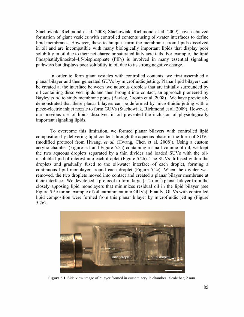
85
Stachowiak, Richmond et al. 2008; Stachowiak, Richmond et al. 2009) have achieved formation of giant vesicles with controlled contents using oil-water interfaces to define lipid membranes. However, these techniques form the membranes from lipids dissolved in oil and are incompatible with many biologically important lipids that display poor solubility in oil due to their net charge or saturated fatty acid tails. For example, the lipid Phosphatidylinositol-4,5-bisphosphate (PIP2) is involved in many essential signaling pathways but displays poor solubility in oil due to its strong negative charge.
In order to form giant vesicles with controlled contents, we first assembled a planar bilayer and then generated GUVs by microfluidic jetting. Planar lipid bilayers can be created at the interface between two aqueous droplets that are initially surrounded by oil containing dissolved lipids and then brought into contact, an approach pioneered by Bayley et al. to study membrane pores (Bayley, Cronin et al. 2008). We have previously demonstrated that these planar bilayers can be deformed by microfluidic jetting with a piezo-electric inkjet nozzle to form GUVs (Stachowiak, Richmond et al. 2009). However, our previous use of lipids dissolved in oil prevented the inclusion of physiologically important signaling lipids.
To overcome this limitation, we formed planar bilayers with controlled lipid composition by delivering lipid content through the aqueous phase in the form of SUVs (modified protocol from Hwang, et al. (Hwang, Chen et al. 2008)). Using a custom acrylic chamber (Figure 5.1 and Figure 5.2a) containing a small volume of oil, we kept the two aqueous droplets separated by a thin divider and loaded SUVs with the oil-insoluble lipid of interest into each droplet (Figure 5.2b). The SUVs diffused within the droplets and gradually fused to the oil-water interface of each droplet, forming a continuous lipid monolayer around each droplet (Figure 5.2c). When the divider was removed, the two droplets moved into contact and created a planar bilayer membrane at their interface. We developed a protocol to form large (~ 2 mm2) planar bilayer from the closely apposing lipid monolayers that minimizes residual oil in the lipid bilayer (see Figure 5.5e for an example of oil entrainment into GUVs) Finally, GUVs with controlled lipid composition were formed from this planar bilayer by microfluidic jetting (Figure 5.2c).
Figure 5.1 Side view image of bilayer formed in custom acrylic chamber. Scale bar, 2 mm.
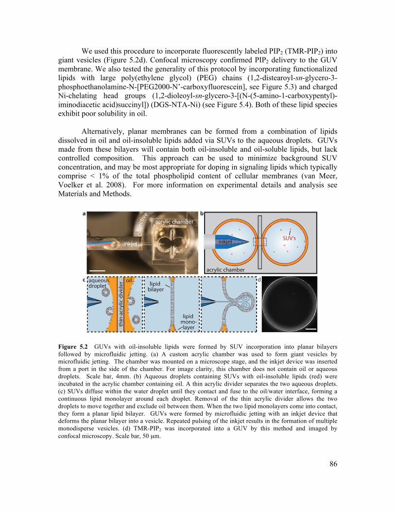
86
We used this procedure to incorporate fluorescently labeled PIP2 (TMR-PIP2) into giant vesicles (Figure 5.2d). Confocal microscopy confirmed PIP2 delivery to the GUV membrane. We also tested the generality of this protocol by incorporating functionalized lipids with large poly(ethylene glycol) (PEG) chains (1,2-distearoyl-sn-glycero-3-phosphoethanolamine-N-[PEG2000-N’-carboxyfluorescein], see Figure 5.3) and charged Ni-chelating head groups (1,2-dioleoyl-sn-glycero-3-[(N-(5-amino-1-carboxypentyl)-iminodiacetic acid)succinyl]) (DGS-NTA-Ni) (see Figure 5.4). Both of these lipid species exhibit poor solubility in oil.
Alternatively, planar membranes can be formed from a combination of lipids dissolved in oil and oil-insoluble lipids added via SUVs to the aqueous droplets. GUVs made from these bilayers will contain both oil-insoluble and oil-soluble lipids, but lack controlled composition. This approach can be used to minimize background SUV concentration, and may be most appropriate for doping in signaling lipids which typically comprise < 1% of the total phospholipid content of cellular membranes (van Meer, Voelker et al. 2008). For more information on experimental details and analysis see Materials and Methods.
Figure 5.2 GUVs with oil-insoluble lipids were formed by SUV incorporation into planar bilayers followed by microfluidic jetting. (a) A custom acrylic chamber was used to form giant vesicles by microfluidic jetting. The chamber was mounted on a microscope stage, and the inkjet device was inserted from a port in the side of the chamber. For image clarity, this chamber does not contain oil or aqueous droplets. Scale bar, 4mm. (b) Aqueous droplets containing SUVs with oil-insoluble lipids (red) were incubated in the acrylic chamber containing oil. A thin acrylic divider separates the two aqueous droplets. (c) SUVs diffuse within the water droplet until they contact and fuse to the oil/water interface, forming a continuous lipid monolayer around each droplet. Removal of the thin acrylic divider allows the two droplets to move together and exclude oil between them. When the two lipid monolayers come into contact, they form a planar lipid bilayer. GUVs were formed by microfluidic jetting with an inkjet device that deforms the planar bilayer into a vesicle. Repeated pulsing of the inkjet results in the formation of multiple monodisperse vesicles. (d) TMR-PIP2 was incorporated into a GUV by this method and imaged by confocal microscopy. Scale bar, 50 µm.
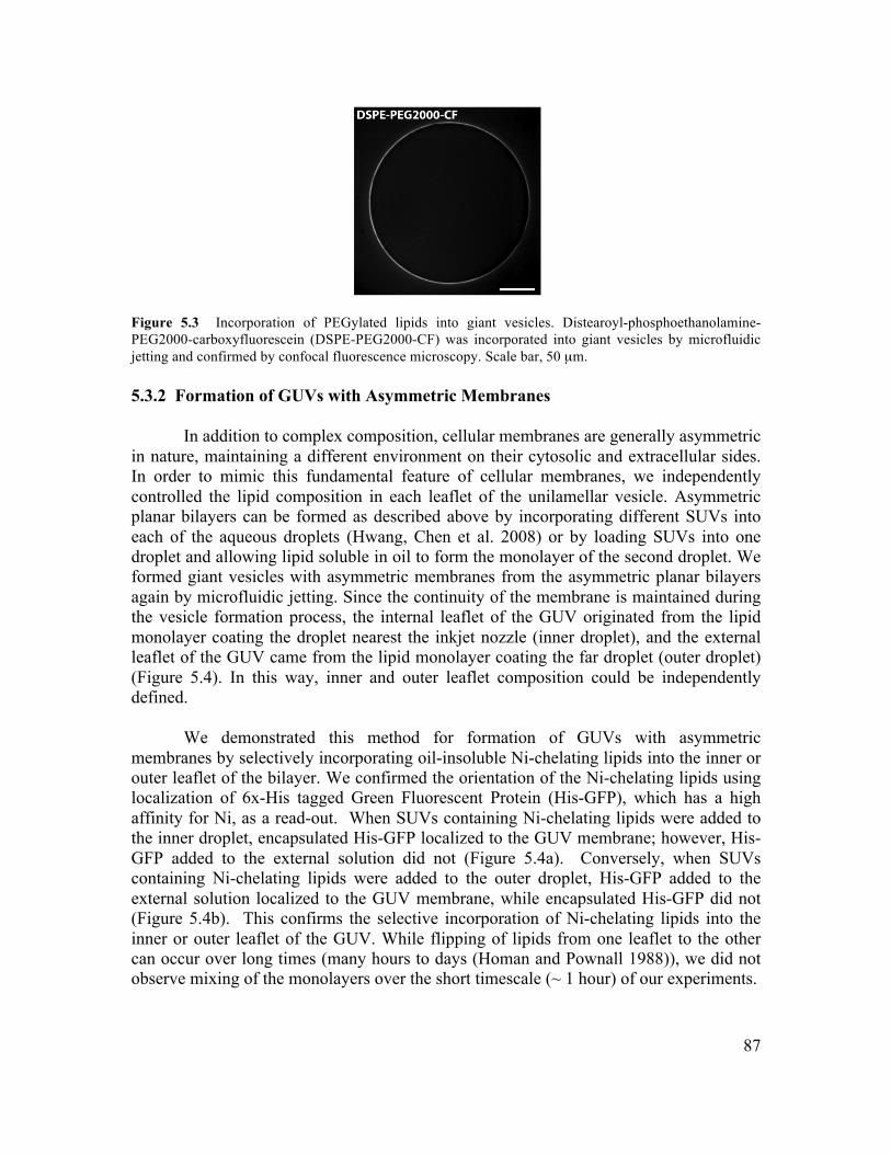
87
Figure 5.3 Incorporation of PEGylated lipids into giant vesicles. Distearoyl-phosphoethanolamine-PEG2000-carboxyfluorescein (DSPE-PEG2000-CF) was incorporated into giant vesicles by microfluidic jetting and confirmed by confocal fluorescence microscopy. Scale bar, 50 µm. 5.3.2 Formation of GUVs with Asymmetric Membranes
In addition to complex composition, cellular membranes are generally asymmetric in nature, maintaining a different environment on their cytosolic and extracellular sides. In order to mimic this fundamental feature of cellular membranes, we independently controlled the lipid composition in each leaflet of the unilamellar vesicle. Asymmetric planar bilayers can be formed as described above by incorporating different SUVs into each of the aqueous droplets (Hwang, Chen et al. 2008) or by loading SUVs into one droplet and allowing lipid soluble in oil to form the monolayer of the second droplet. We formed giant vesicles with asymmetric membranes from the asymmetric planar bilayers again by microfluidic jetting. Since the continuity of the membrane is maintained during the vesicle formation process, the internal leaflet of the GUV originated from the lipid monolayer coating the droplet nearest the inkjet nozzle (inner droplet), and the external leaflet of the GUV came from the lipid monolayer coating the far droplet (outer droplet) (Figure 5.4). In this way, inner and outer leaflet composition could be independently defined.
We demonstrated this method for formation of GUVs with asymmetric membranes by selectively incorporating oil-insoluble Ni-chelating lipids into the inner or outer leaflet of the bilayer. We confirmed the orientation of the Ni-chelating lipids using localization of 6x-His tagged Green Fluorescent Protein (His-GFP), which has a high affinity for Ni, as a read-out. When SUVs containing Ni-chelating lipids were added to the inner droplet, encapsulated His-GFP localized to the GUV membrane; however, His-GFP added to the external solution did not (Figure 5.4a). Conversely, when SUVs containing Ni-chelating lipids were added to the outer droplet, His-GFP added to the external solution localized to the GUV membrane, while encapsulated His-GFP did not (Figure 5.4b). This confirms the selective incorporation of Ni-chelating lipids into the inner or outer leaflet of the GUV. While flipping of lipids from one leaflet to the other can occur over long times (many hours to days (Homan and Pownall 1988)), we did not observe mixing of the monolayers over the short timescale (~ 1 hour) of our experiments.
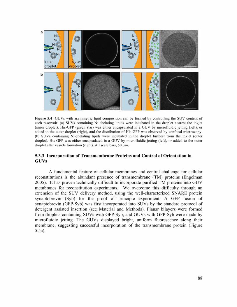
88
Figure 5.4 GUVs with asymmetric lipid composition can be formed by controlling the SUV content of each reservoir. (a) SUVs containing Ni-chelating lipids were incubated in the droplet nearest the inkjet (inner droplet). His-GFP (green star) was either encapsulated in a GUV by microfluidic jetting (left), or added to the outer droplet (right), and the distribution of His-GFP was observed by confocal microscopy. (b) SUVs containing Ni-chelating lipids were incubated in the droplet furthest from the inkjet (outer droplet). His-GFP was either encapsulated in a GUV by microfluidic jetting (left), or added to the outer droplet after vesicle formation (right). All scale bars, 50 µm. 5.3.3 Incorporation of Transmembrane Proteins and Control of Orientation in GUVs
A fundamental feature of cellular membranes and central challenge for cellular reconstitutions is the abundant presence of transmembrane (TM) proteins (Engelman 2005). It has proven technically difficult to incorporate purified TM proteins into GUV membranes for reconstitution experiments. We overcome this difficulty through an extension of the SUV delivery method, using the well-characterized SNARE protein synaptobrevin (Syb) for the proof of principle experiment. A GFP fusion of synaptobrevin (GFP-Syb) was first incorporated into SUVs by the standard protocol of detergent assisted insertion (see Material and Methods). Planar bilayers were formed from droplets containing SUVs with GFP-Syb, and GUVs with GFP-Syb were made by microfluidic jetting. The GUVs displayed bright, uniform fluorescence along their membrane, suggesting successful incorporation of the transmembrane protein (Figure 5.5a).
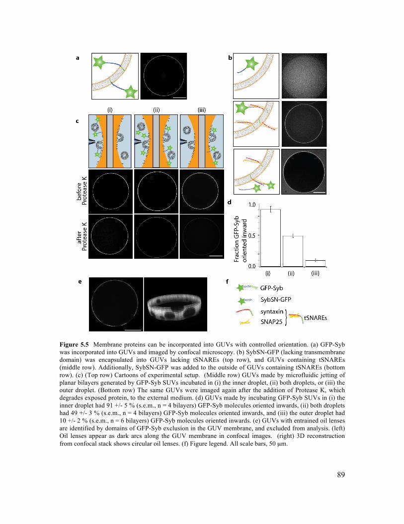
89
Figure 5.5 Membrane proteins can be incorporated into GUVs with controlled orientation. (a) GFP-Syb was incorporated into GUVs and imaged by confocal microscopy. (b) SybSN-GFP (lacking transmembrane domain) was encapsulated into GUVs lacking tSNAREs (top row), and GUVs containing tSNAREs (middle row). Additionally, SybSN-GFP was added to the outside of GUVs containing tSNAREs (bottom row). (c) (Top row) Cartoons of experimental setup. (Middle row) GUVs made by microfluidic jetting of planar bilayers generated by GFP-Syb SUVs incubated in (i) the inner droplet, (ii) both droplets, or (iii) the outer droplet. (Bottom row) The same GUVs were imaged again after the addition of Protease K, which degrades exposed protein, to the external medium. (d) GUVs made by incubating GFP-Syb SUVs in (i) the inner droplet had 91 +/- 5 % (s.e.m., n = 4 bilayers) GFP-Syb molecules oriented inwards, (ii) both droplets had 49 +/- 3 % (s.e.m., n = 4 bilayers) GFP-Syb molecules oriented inwards, and (iii) the outer droplet had 10 +/- 2 % (s.e.m., n = 6 bilayers) GFP-Syb molecules oriented inwards. (e) GUVs with entrained oil lenses are identified by domains of GFP-Syb exclusion in the GUV membrane, and excluded from analysis. (left) Oil lenses appear as dark arcs along the GUV membrane in confocal images. (right) 3D reconstruction from confocal stack shows circular oil lenses. (f) Figure legend. All scale bars, 50 µm.
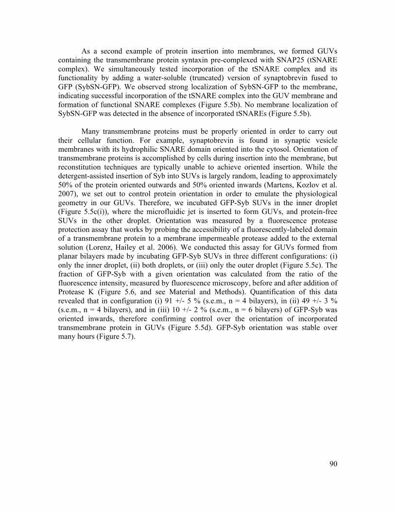
90
As a second example of protein insertion into membranes, we formed GUVs containing the transmembrane protein syntaxin pre-complexed with SNAP25 (tSNARE complex). We simultaneously tested incorporation of the tSNARE complex and its functionality by adding a water-soluble (truncated) version of synaptobrevin fused to GFP (SybSN-GFP). We observed strong localization of SybSN-GFP to the membrane, indicating successful incorporation of the tSNARE complex into the GUV membrane and formation of functional SNARE complexes (Figure 5.5b). No membrane localization of SybSN-GFP was detected in the absence of incorporated tSNAREs (Figure 5.5b).
Many transmembrane proteins must be properly oriented in order to carry out their cellular function. For example, synaptobrevin is found in synaptic vesicle membranes with its hydrophilic SNARE domain oriented into the cytosol. Orientation of transmembrane proteins is accomplished by cells during insertion into the membrane, but reconstitution techniques are typically unable to achieve oriented insertion. While the detergent-assisted insertion of Syb into SUVs is largely random, leading to approximately 50% of the protein oriented outwards and 50% oriented inwards (Martens, Kozlov et al. 2007), we set out to control protein orientation in order to emulate the physiological geometry in our GUVs. Therefore, we incubated GFP-Syb SUVs in the inner droplet (Figure 5.5c(i)), where the microfluidic jet is inserted to form GUVs, and protein-free SUVs in the other droplet. Orientation was measured by a fluorescence protease protection assay that works by probing the accessibility of a fluorescently-labeled domain of a transmembrane protein to a membrane impermeable protease added to the external solution (Lorenz, Hailey et al. 2006). We conducted this assay for GUVs formed from planar bilayers made by incubating GFP-Syb SUVs in three different configurations: (i) only the inner droplet, (ii) both droplets, or (iii) only the outer droplet (Figure 5.5c). The fraction of GFP-Syb with a given orientation was calculated from the ratio of the fluorescence intensity, measured by fluorescence microscopy, before and after addition of Protease K (Figure 5.6, and see Material and Methods). Quantification of this data revealed that in configuration (i) 91 +/- 5 % (s.e.m., n = 4 bilayers), in (ii) 49 +/- 3 % (s.e.m., n = 4 bilayers), and in (iii) 10 +/- 2 % (s.e.m., n = 6 bilayers) of GFP-Syb was oriented inwards, therefore confirming control over the orientation of incorporated transmembrane protein in GUVs (Figure 5.5d). GFP-Syb orientation was stable over many hours (Figure 5.7).
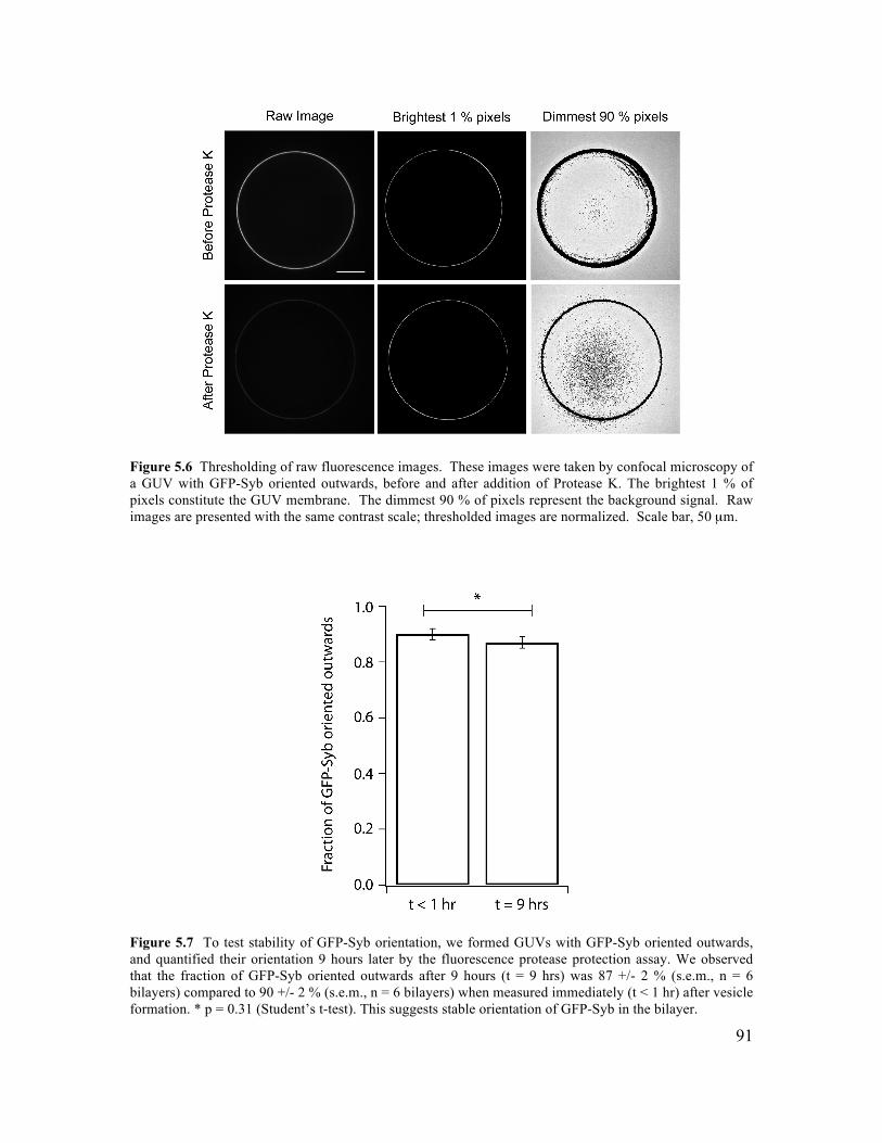
91
Figure 5.6 Thresholding of raw fluorescence images. These images were taken by confocal microscopy of a GUV with GFP-Syb oriented outwards, before and after addition of Protease K. The brightest 1 % of pixels constitute the GUV membrane. The dimmest 90 % of pixels represent the background signal. Raw images are presented with the same contrast scale; thresholded images are normalized. Scale bar, 50 µm.
Figure 5.7 To test stability of GFP-Syb orientation, we formed GUVs with GFP-Syb oriented outwards, and quantified their orientation 9 hours later by the fluorescence protease protection assay. We observed that the fraction of GFP-Syb oriented outwards after 9 hours (t = 9 hrs) was 87 +/- 2 % (s.e.m., n = 6 bilayers) compared to 90 +/- 2 % (s.e.m., n = 6 bilayers) when measured immediately (t < 1 hr) after vesicle formation. * p = 0.31 (Student’s t-test). This suggests stable orientation of GFP-Syb in the bilayer.
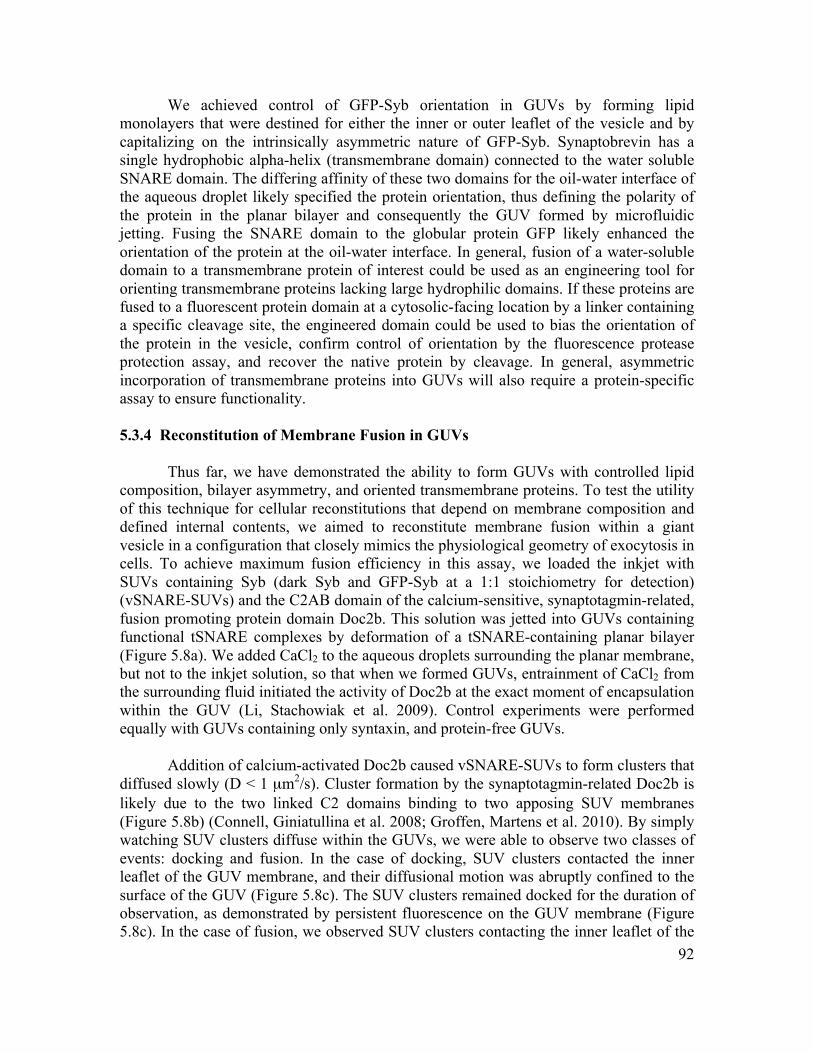
92
We achieved control of GFP-Syb orientation in GUVs by forming lipid monolayers that were destined for either the inner or outer leaflet of the vesicle and by capitalizing on the intrinsically asymmetric nature of GFP-Syb. Synaptobrevin has a single hydrophobic alpha-helix (transmembrane domain) connected to the water soluble SNARE domain. The differing affinity of these two domains for the oil-water interface of the aqueous droplet likely specified the protein orientation, thus defining the polarity of the protein in the planar bilayer and consequently the GUV formed by microfluidic jetting. Fusing the SNARE domain to the globular protein GFP likely enhanced the orientation of the protein at the oil-water interface. In general, fusion of a water-soluble domain to a transmembrane protein of interest could be used as an engineering tool for orienting transmembrane proteins lacking large hydrophilic domains. If these proteins are fused to a fluorescent protein domain at a cytosolic-facing location by a linker containing a specific cleavage site, the engineered domain could be used to bias the orientation of the protein in the vesicle, confirm control of orientation by the fluorescence protease protection assay, and recover the native protein by cleavage. In general, asymmetric incorporation of transmembrane proteins into GUVs will also require a protein-specific assay to ensure functionality. 5.3.4 Reconstitution of Membrane Fusion in GUVs
Thus far, we have demonstrated the ability to form GUVs with controlled lipid composition, bilayer asymmetry, and oriented transmembrane proteins. To test the utility of this technique for cellular reconstitutions that depend on membrane composition and defined internal contents, we aimed to reconstitute membrane fusion within a giant vesicle in a configuration that closely mimics the physiological geometry of exocytosis in cells. To achieve maximum fusion efficiency in this assay, we loaded the inkjet with SUVs containing Syb (dark Syb and GFP-Syb at a 1:1 stoichiometry for detection) (vSNARE-SUVs) and the C2AB domain of the calcium-sensitive, synaptotagmin-related, fusion promoting protein domain Doc2b. This solution was jetted into GUVs containing functional tSNARE complexes by deformation of a tSNARE-containing planar bilayer (Figure 5.8a). We added CaCl2 to the aqueous droplets surrounding the planar membrane, but not to the inkjet solution, so that when we formed GUVs, entrainment of CaCl2 from the surrounding fluid initiated the activity of Doc2b at the exact moment of encapsulation within the GUV (Li, Stachowiak et al. 2009). Control experiments were performed equally with GUVs containing only syntaxin, and protein-free GUVs.
Addition of calcium-activated Doc2b caused vSNARE-SUVs to form clusters that
diffused slowly (D < 1 µm2/s). Cluster formation by the synaptotagmin-related Doc2b is likely due to the two linked C2 domains binding to two apposing SUV membranes (Figure 5.8b) (Connell, Giniatullina et al. 2008; Groffen, Martens et al. 2010). By simply watching SUV clusters diffuse within the GUVs, we were able to observe two classes of events: docking and fusion. In the case of docking, SUV clusters contacted the inner leaflet of the GUV membrane, and their diffusional motion was abruptly confined to the surface of the GUV (Figure 5.8c). The SUV clusters remained docked for the duration of observation, as demonstrated by persistent fluorescence on the GUV membrane (Figure 5.8c). In the case of fusion, we observed SUV clusters contacting the inner leaflet of the
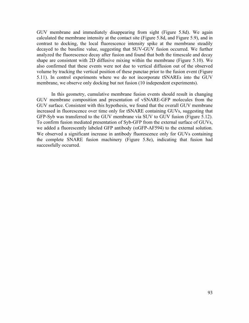
93
GUV membrane and immediately disappearing from sight (Figure 5.8d). We again calculated the membrane intensity at the contact site (Figure 5.8d, and Figure 5.9), and in contrast to docking, the local fluorescence intensity spike at the membrane steadily decayed to the baseline value, suggesting that SUV-GUV fusion occurred. We further analyzed the fluorescence decay after fusion and found that both the timescale and decay shape are consistent with 2D diffusive mixing within the membrane (Figure 5.10). We also confirmed that these events were not due to vertical diffusion out of the observed volume by tracking the vertical position of these punctae prior to the fusion event (Figure 5.11). In control experiments where we do not incorporate tSNAREs into the GUV membrane, we observe only docking but not fusion (10 independent experiments).
In this geometry, cumulative membrane fusion events should result in changing
GUV membrane composition and presentation of vSNARE-GFP molecules from the GUV surface. Consistent with this hypothesis, we found that the overall GUV membrane increased in fluorescence over time only for tSNARE containing GUVs, suggesting that GFP-Syb was transferred to the GUV membrane via SUV to GUV fusion (Figure 5.12). To confirm fusion mediated presentation of Syb-GFP from the external surface of GUVs, we added a fluorescently labeled GFP antibody (αGFP-AF594) to the external solution. We observed a significant increase in antibody fluorescence only for GUVs containing the complete SNARE fusion machinery (Figure 5.8e), indicating that fusion had successfully occurred.

94
Figure 5.8 Reconstitution of membrane fusion leads to transfer of SNARE proteins from the inner leaflet of SUVs to the outer leaflet of GUVs. (a) GUVs were formed with incorporated tSNAREs and encapsulated Doc2 and vSNARE-SUVs. Ca2+ was entrained from the aqueous droplets during the formation process. (b) Confocal image of vSNARE-SUVs encapsulated in a tSNARE-GUV (c) Docking of an SUV cluster to a GUV. Diffusion of an encapsulated SUV cluster was tracked for 10 minutes. The location of the SUV cluster in the first frame is denoted by ‘x’. The track is separated into before (red) and after (green) docking to the GUV membrane. Fluorescence intensity of the GUV membrane at the docking location (yellow box) is shown for 2 minutes around the docking event. (d) Fusion of an SUV cluster to a GUV. The path of an SUV cluster was tracked (red) for 5 minutes, until fusion with the GUV membrane. The location of the SUV cluster in the first frame is denoted by ‘x’. Fluorescence intensity of the GUV membrane at the fusion location (yellow box) is shown for 2 minutes around the fusion event. Fluorescence decay is fit by a 2D diffusion model (R2 = 0.81, see Materials and Methods). (e) Membrane fusion was confirmed by addition of fluorescently labeled antibody against GFP to the external solution. Fluorescence intensity of GUV membranes containing syntaxin + SNAP25 (tSNAREs) increased by 5922 +/- 2108 a.u. (s.e.m., n = 6 bilayers), whereas GUV membranes containing only syntaxin, or no SNARE proteins, increased by 816 +/- 193 a.u. (s.e.m., n = 7 bilayers) and 506 +/- 419 a.u. (s.e.m., n = 5 bilayers), respectively. * p < 0.05 (Student’s t-test). All scale bars, 25 µm.
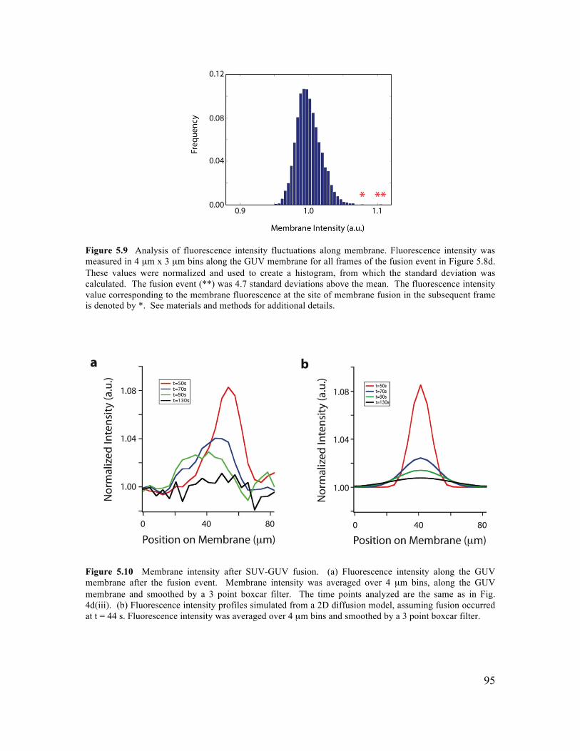
95
Figure 5.9 Analysis of fluorescence intensity fluctuations along membrane. Fluorescence intensity was measured in 4 µm x 3 µm bins along the GUV membrane for all frames of the fusion event in Figure 5.8d. These values were normalized and used to create a histogram, from which the standard deviation was calculated. The fusion event (**) was 4.7 standard deviations above the mean. The fluorescence intensity value corresponding to the membrane fluorescence at the site of membrane fusion in the subsequent frame is denoted by *. See materials and methods for additional details.
Figure 5.10 Membrane intensity after SUV-GUV fusion. (a) Fluorescence intensity along the GUV membrane after the fusion event. Membrane intensity was averaged over 4 µm bins, along the GUV membrane and smoothed by a 3 point boxcar filter. The time points analyzed are the same as in Fig. 4d(iii). (b) Fluorescence intensity profiles simulated from a 2D diffusion model, assuming fusion occurred at t = 44 s. Fluorescence intensity was averaged over 4 µm bins and smoothed by a 3 point boxcar filter.
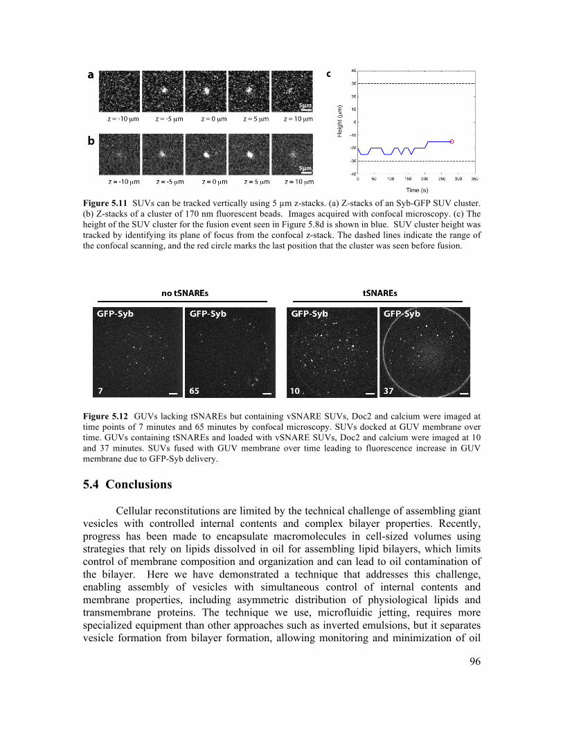
96
Figure 5.11 SUVs can be tracked vertically using 5 µm z-stacks. (a) Z-stacks of an Syb-GFP SUV cluster. (b) Z-stacks of a cluster of 170 nm fluorescent beads. Images acquired with confocal microscopy. (c) The height of the SUV cluster for the fusion event seen in Figure 5.8d is shown in blue. SUV cluster height was tracked by identifying its plane of focus from the confocal z-stack. The dashed lines indicate the range of the confocal scanning, and the red circle marks the last position that the cluster was seen before fusion.
Figure 5.12 GUVs lacking tSNAREs but containing vSNARE SUVs, Doc2 and calcium were imaged at time points of 7 minutes and 65 minutes by confocal microscopy. SUVs docked at GUV membrane over time. GUVs containing tSNAREs and loaded with vSNARE SUVs, Doc2 and calcium were imaged at 10 and 37 minutes. SUVs fused with GUV membrane over time leading to fluorescence increase in GUV membrane due to GFP-Syb delivery. 5.4 Conclusions
Cellular reconstitutions are limited by the technical challenge of assembling giant
vesicles with controlled internal contents and complex bilayer properties. Recently, progress has been made to encapsulate macromolecules in cell-sized volumes using strategies that rely on lipids dissolved in oil for assembling lipid bilayers, which limits control of membrane composition and organization and can lead to oil contamination of the bilayer. Here we have demonstrated a technique that addresses this challenge, enabling assembly of vesicles with simultaneous control of internal contents and membrane properties, including asymmetric distribution of physiological lipids and transmembrane proteins. The technique we use, microfluidic jetting, requires more specialized equipment than other approaches such as inverted emulsions, but it separates vesicle formation from bilayer formation, allowing monitoring and minimization of oil
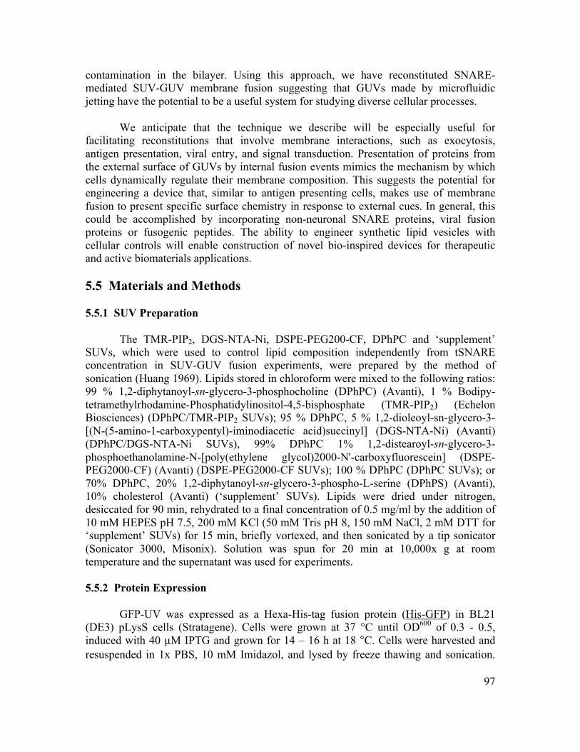
97
contamination in the bilayer. Using this approach, we have reconstituted SNARE-mediated SUV-GUV membrane fusion suggesting that GUVs made by microfluidic jetting have the potential to be a useful system for studying diverse cellular processes.
We anticipate that the technique we describe will be especially useful for facilitating reconstitutions that involve membrane interactions, such as exocytosis, antigen presentation, viral entry, and signal transduction. Presentation of proteins from the external surface of GUVs by internal fusion events mimics the mechanism by which cells dynamically regulate their membrane composition. This suggests the potential for engineering a device that, similar to antigen presenting cells, makes use of membrane fusion to present specific surface chemistry in response to external cues. In general, this could be accomplished by incorporating non-neuronal SNARE proteins, viral fusion proteins or fusogenic peptides. The ability to engineer synthetic lipid vesicles with cellular controls will enable construction of novel bio-inspired devices for therapeutic and active biomaterials applications. 5.5 Materials and Methods 5.5.1 SUV Preparation
The TMR-PIP2, DGS-NTA-Ni, DSPE-PEG200-CF, DPhPC and ‘supplement’ SUVs, which were used to control lipid composition independently from tSNARE concentration in SUV-GUV fusion experiments, were prepared by the method of sonication (Huang 1969). Lipids stored in chloroform were mixed to the following ratios: 99 % 1,2-diphytanoyl-sn-glycero-3-phosphocholine (DPhPC) (Avanti), 1 % Bodipy-tetramethylrhodamine-Phosphatidylinositol-4,5-bisphosphate (TMR-PIP2) (Echelon Biosciences) (DPhPC/TMR-PIP2 SUVs); 95 % DPhPC, 5 % 1,2-dioleoyl-sn-glycero-3-[(N-(5-amino-1-carboxypentyl)-iminodiacetic acid)succinyl] (DGS-NTA-Ni) (Avanti) (DPhPC/DGS-NTA-Ni SUVs), 99% DPhPC 1% 1,2-distearoyl-sn-glycero-3-phosphoethanolamine-N-[poly(ethylene glycol)2000-N'-carboxyfluorescein] (DSPE-PEG2000-CF) (Avanti) (DSPE-PEG2000-CF SUVs); 100 % DPhPC (DPhPC SUVs); or 70% DPhPC, 20% 1,2-diphytanoyl-sn-glycero-3-phospho-L-serine (DPhPS) (Avanti), 10% cholesterol (Avanti) (‘supplement’ SUVs). Lipids were dried under nitrogen, desiccated for 90 min, rehydrated to a final concentration of 0.5 mg/ml by the addition of 10 mM HEPES pH 7.5, 200 mM KCl (50 mM Tris pH 8, 150 mM NaCl, 2 mM DTT for ‘supplement’ SUVs) for 15 min, briefly vortexed, and then sonicated by a tip sonicator (Sonicator 3000, Misonix). Solution was spun for 20 min at 10,000x g at room temperature and the supernatant was used for experiments. 5.5.2 Protein Expression
GFP-UV was expressed as a Hexa-His-tag fusion protein (His-GFP) in BL21 (DE3) pLysS cells (Stratagene). Cells were grown at 37 °C until OD600 of 0.3 - 0.5, induced with 40 µM IPTG and grown for 14 – 16 h at 18 °C. Cells were harvested and resuspended in 1x PBS, 10 mM Imidazol, and lysed by freeze thawing and sonication.
98
The lysate was centrifuged for 45 min at 20,000 g, 4 °C and the supernatant was incubated with 0.5 ml of Ni-NTA Agarose beads (Quiagen) per 1 l of culture for 1 – 2 h. Beads were washed 7x with 1x PBS, 10 mM Imidazol and 2x for 15 min in the same buffer. The protein was eluted with 1x PBS, 150 mM Imidazole, dialysed into 1x PBS, concentrated, aliquoted and frozen.
eGFP- rat synaptobrevin (GFP-tag fused to the N-terminus of synaptobrevin (NP_036795), GFP-Syb,) was expressed as a Hexa-His-tag fusion in BL21(DE3) pLysS cells (Stratagene). Cells were grown at 37 °C until OD600 of 0.9 - 1, induced with 40 µM IPTG and grown for 14 – 16 h at 18 °C. Cells were harvested and resuspended in 25 mM HEPES pH 7.5, 400 mM KCl, 5% Triton X-100, 2 mM MgCl2, 1 mM βMercaptoethanol (bMe), EDTA-free Complete protease inhibitors (Roche), DNaseI. Cells were lysed by freeze thawing and the lysate was centrifuged for 45 min at 125,000 g, 4 0C. Supernatant was incubated with 2 ml of Ni-NTA Agarose beads (Qiagen) per 1 l of culture for 2 h. Beads were washed 7x with 25 mM HEPES pH 7.5, 400 mM KCl, 1 % Triton X-100, 1 mM bMe, 3 more wash steps with increasing concentrations of Imidazole up to 25 mM. Beads were washed 5x with 25 mM HEPES pH 7.5, 100 mM KCl, 10 % glycerol, 1 % w/v n-octyl-D-glucopyranoside (OGP), 1 mM bMe and then resuspended in 10 ml 25 mM HEPES pH 7.5, 100 mM KCl, 10 % glycerol, 1 % w/v OGP, 1 mM bMe and cleaved with thrombin over night at 4 0C, and further 8 hours at room temperature. 10 mM Imidazole was added to the beads and incubated for 30 min at room temperature. Supernatant was concentrated and beads were washed with 25 mM HEPES pH 7.5, 100 mM KCl, 10 % glycerol, 1 % w/v OGP, 1 mM bMe, supernatant was pooled (50 ml) and concentrated, protein was aliquoted and frozen.
The truncated, water-soluble domain of rat synaptobrevin (amino acid 1-96) fused to eGFP (GFP-tag at C-terminus of protein domain, SybSN-GFP) was expressed as Hexa-His tag fusion protein. Cells were grown at 37 °C until OD600 of 0.3 - 0.5, induced with 40 µM IPTG and grown over night at 18 °C. Cells were harvested and resuspended in 25 mM HEPES pH 7.5, 400 mM KCl, 5 % Triton X-100, 2 mM MgCl2, 1 mM bMe, EDTA-free Complete protease inhibitors (Roche), DNaseI. Cells were lysed by freeze thawing and the lysate was centrifuged for 45 min at 20,000 g, 4 0C. Supernatant was incubated with 0.5 ml of Nickel beads (Qiagen) per 1 l of culture for 2 h. Beads were washed 7x with 25 mM HEPES pH 7.5, 400 mM KCl, 1 mM bMe, 3 more washsteps with increasing concentrations of Imidazole up to 25 mM. Protein was eluted with 150 mM Imidazole, dialysed into 25 mM HEPES pH 7.5, 100 mM KCl, 2 mM DTT, aliquoted and frozen.
The rat Doc2b (NP_112404) C2AB domain fragment (amino acid 125-412, doc2) was expressed as GST fusion protein in BL21 (DE3) pLysS cells. Cells were grown at 37 °C until OD600 of 0.3, induced with 40 µM IPTG and grown for 14 – 16 h at 18 °C. Cells were harvested and resuspended in 50 mM HEPES pH 7.5, 300 mM NaCl 4 mM DTT, 2 mM MgCl2, DNaseI, RNaseA, EDTA-free Complete protease inhibitors and lysed by freeze thawing. The lysate was centrifuged for 45 min at 125,000 g, 4 °C and the supernatant was incubated with 1 ml of glutathione-sepharose beads per 1 l of culture for 1 – 2 h. Beads were washed 7x with 50 mM HEPES pH 7.5, 300 mM NaCl, 4 mM DTT
99
followed by two 15 min washes with 50 mM HEPES pH 7.5, 500 mM NaCl, 4 mM DTT, 2 mM MgCl2, DNaseI, RNaseA. The protein was cleaved off the beads with thrombin by over night incubation at 16 °C. The supernatant was concentrated and the protein was further purified by gel filtration in 50 mM HEPES pH 7.5, 150 mM NaCl, 4 mM DTT using a HiLoad 16/60 Superdex 75 column (Pharmacia Biotech). The protein was concentrated again, shock frozen and stored at -80 °C.
Rat full length synaptobrevin (NP_036795, Syb), full-length SNAP25b (NP_112253, SNAP25) and a syntaxin1a (NP_446240) construct (amino acid 180-288) that lacks the N-terminal regulatory domain, which is composed of the helices Ha, Hb and Hc (syntaxin1a ΔHabc), were expressed as GST fusion. Expression was conducted as described previously, protocol for syntaxin1a ΔHabc equals SNAP25.
Possible protein and RNA contamination was checked by SDS gel electrophoresis and UV spectroscopy, respectively. The functionality of SNARE proteins was monitored by SDS-resistant SNARE complex formation. 5.5.3 Proteo-Liposome Preparation GFP-Syb, tSNARE, syntaxin-only and vSNARE SUVs were prepared by detergent assisted insertion into pre-formed SUVs. For GFP-Syb SUVs DPhPC lipids in chloroform were dried under nitrogen and desiccated for 90 min. Lipids were rehydrated in 50 mM Tris pH 8, 150 mM NaCl, 2 mM DTT for 15 min at room temperature and tip sonicated to create a 10 mM SUV solution. Solution was spun for 20 min at 10,000x g at room temperature to spin out aggregates. 20 µl of the SUVs were added to 80 µl of a 10 µM solution of GFP-Syb and incubated for 15 min at room temperature. The detergent was diluted below the critical micelle concentration by the addition of 100 µl 25 mM HEPES pH 7.4, 100 mM KCl, 2mM DTT, subsequently dialyzed against 2 L of 25 mM HEPES pH 7.4, 100 mM KCl, 2mM DTT and 10 g BioBeads (BioRad) over night at 4 °C to remove the detergent and spun at 10,000x g for 5 min at room temperature to remove aggregates. The supernatant was used for experiments. tSNARE SUVs were prepared as described for GFP-Syb SUVs except that 10 µl of 20mg/ml DPhPC SUVs were added to 90 µl of an 11.1 µM preformed tSNARE complex solution (1:1 SNAP25 and syntaxinΔHabc, 1hr room temperature). Syntaxin-only SUVs were prepared as described for tSNARE SUVs except that SNAP25 was omitted. vSNARE SUVs were prepared similarly to GFP-Syb SUVs except that 20µl of a 10 mM SUV mix (70 % DPhPC, 15 % DPhPS, 10% Cholesterol, 5 % DPhPE (1,2-diphytanoyl-sn-glycero-3-phosphoethanolamine, Avanti) were added to 80 µl of a premixed solution of 5 µM Syb and 5 µM GFP-Syb . 5.5.4 Chamber Design
Chambers were designed with two cylindrical bores (4.3 mm diameter) separated by a 0.5 mm wide slot through the center that holds a thin acrylic divider. When the divider is removed, it leaves a 3 mm wide ‘window’ between the two cylinders.
100
Chambers were cut from sheets of 4.5 mm thick acrylic (McMaster-Carr) using a laser cutter (Versa Laser). A 1.5 mm hole was drilled in one end of the chamber, and covered by a 0.26 mm latex film (McMaster-Carr), forming a seal. A small hole was made in the latex film with a 23G needle to allow insertion and alignment of the inkjet nozzle (Figure 5.2a). Finally, a thin (0.2 mm) acrylic coverslip (Astra products) was cemented (acrylic cement, TAP plastics) to the bottom of the chamber. Chambers were cleaned with 2 % Neutrad (Decon Laboratories) solution at 60 °C, thoroughly rinsed and re-used multiple times. 5.5.5 Planar Bilayer Formation A planar bilayer was prepared by incubating two SUV containing droplets (45 µl each), separated by a thin (0.2 mm) acrylic divider, in an oil (decane, 40 µl total) loaded acrylic chamber (Figure 5.1 and Figure 5.2b). Incubation was typically done overnight at 4 °C. However, when forming asymmetric (protein-free) lipid bilayers, the incubation time was reduced to tens of minutes to prevent transbilayer mixing of lipids by diffusion through the oil. SUV concentrations in the droplets ranged from 0.02 – 0.5 mg/ml. Typically, if 0.1 mg/ml or lower SUVs were used, 30 µl of 50 mg/ml DPhPC was added to the oil to a final concentration of 21 mg/ml shortly before bilayer formation to improve stability of the bilayer (this was unnecessary when higher SUV concentrations were used). DPhPC lipids are commonly used in black membrane experiments, and are ideal because of their solubility in oil, low melting temperature and stability against oxidation (Collins and Keller 2008). Bilayer formation was initiated by removal of the thin acrylic divider. Bilayers were typically stable for more than 1 hour. 5.5.6 GUV Formation by Microfluidic Jetting
GUVs were formed by microfluidic jetting against planar bilayer substrates, as described previously (Stachowiak, Richmond et al. 2009). Briefly, a micro-nozzle was formed by pulling a glass capillary (0.6 mm ID, 0.75 mm OD) to a fine tip using a P-97 Micropipette Puller (Sutter Instruments), and then subsequently melting and sanding the tip until the orifice was 10-15 µm ID. Micro-nozzles were mounted into piezo-electric inkjet devices by MicroFab Technologies, and are referred to as inkjets. Contents to be encapsulated in GUVs were loaded into a disposable syringe, and back-filled into an inkjet. An acrylic chamber containing a pre-formed bilayer was mounted on an Axiovert 200 inverted microscope (Carl Zeiss), and the inkjet nozzle was inserted through the small hole in the latex film and aligned within 200 µm from the planar bilayer (Figure 5.1 and Figure 5.2). A 10-20 minute waiting period was typically sufficient to allow oil lenses to evacuate the planar bilayer. The presence of oil lenses can be observed by light microscopy (Li, Stachowiak et al. 2009) and bilayer thinning can be facilitated by agitating the planar bilayer with the microfluidic jet. A microfluidic jet was formed from multiple pulses of the piezo-electric inkjet, and the pulse train was controlled by the drive electronics (MicroJet III controller box, MicroFab Technologies). Typical shot profiles were 15 - 35 identical trapezoidal pulses repeated at 20 kHz with 25-35 V amplitude, and 3 µs rise time, 35 µs duration and 3 µs fall time. A wide range of solutions were

101
encapsulated in GUVs using this technique, but the encapsulated solution was always osmotically balanced to the inner and outer droplet solutions, and typically contained > 100 mOsm sucrose, or 6 % iodixanol (Sigma-Aldrich) to sink the GUV for ease of imaging. Vesicle formation was recorded using a high-speed camera (1024PCI, Photron). After formation, GUVs were assessed for the presence of entrained oil. Oil lenses were easily identified by increased signal from fluorescently labeled lipids or the exclusion of transmembrane proteins in this domain (Figure 5.5e), and can also be identified by phase contrast differences using phase microscopy. GUVs containing significant oil were excluded from our analysis. In order to characterize success rate of vesicle formation, we recorded the fraction of bilayers from which vesicles were made, for each of five consecutive days of experiments. On average, vesicles were formed each day from 66% +/- 13% (s.e.m.) of bilayers (n = 30 bilayers). 5.5.7 Incorporating TMR-PIP2 into GUVs Aqueous droplets containing 0.1 mg/ml DPhPC/TMR-PIP2 SUVs were added to both sides of the oil-loaded chamber, and the chamber was incubated overnight at 4 °C. The thin acrylic divider was removed, and the chamber was left for 10 minutes to allow for planar bilayer formation before an inkjet loaded with 350 mOsm sucrose was used to form GUVs by microfluidic jetting. 5.5.8 Asymmetric DGS-NTA-Ni GUV Experiment In order to selectively incorporate DGS-NTA-Ni into the inner leaflet of a GUV the oil containing chamber was set up with an inner droplet containing 0.02 mg/ml DPhPC/DGS-NTA-Ni SUVs and an outer droplet containing 0.02 mg/ml DPhPC SUVs, and was incubated for one hour. After incubation, DPhPC in oil was added to a final concentration of 21 mg/ml in the chamber. The thin acrylic divider was removed and GUVs were formed using an inkjet containing either 2 µM His-GFP and 6 % iodixanol in 10 mM Hepes pH 7.5, 200 mM KCl (Figure 5.4a, left), or only 6 % iodixanol in 10mM Hepes pH 7.5, 200 mM KCl (Figure 5.4a, right). After formation of multiple GUVs from a single bilayer, the sample was transferred to a spinning disc confocal microscope for imaging. GUVs with encapsulated His-GFP were imaged immediately. 0.3 µM His-GFP was added to chambers with GUVs lacking encapsulated His-GFP, and they were incubated for 30 min before imaging. Selective incorporation of DGS-NTA-Ni into the outer leaflet of a GUV was accomplished by repeating this procedure, with 0.02 mg/ml DPhPC/DGS-NTA-Ni SUVs in the outer droplet and 0.02 mg/ml DPhPC SUVs in the inner droplet (Figure 5.4b). 5.5.9 tSNARE Incorporation and Functional SNARE Complex Formation Aqueous droplets containing either 0.05 mg/ml tSNARE SUVs (DPhPC SUVs with inserted tSNARE complexes) and 0.05 mg/ml supplement SUVs (DPhPC/DPhPS/cholesterol 70/20/10) or 0.1 mg/ml supplement SUVs only (control), in 25 mM HEPES pH 7.5, 100 mM KCl, 2 mM DTT were added to both sides of an oil-loaded chamber, and the chamber was incubated overnight at 4 °C. After incubation,
102
DPhPC in oil was added to a final concentration of 21 mg/ml in the chamber. The thin acrylic divider was removed, forming a tSNARE containing planar bilayer, and an inkjet loaded with 1 µM SybSN-GFP, 6 % iodixanol, 25 mM HEPES pH 7.5, 100 mM KCl and 2 mM DTT was used to form GUVs. Alternatively, binding of SybSN-GFP to tSNAREs in the external leaflet of GUVs was tested by addition of 1 µM SybSN-GFP to the chamber after vesicle formation, instead of loading it into the inkjet. 5.5.10 Syb-GFP Incorporation and Orientation In order to form GUVs with GFP-Syb with the GFP domain facing outwards the oil containing chamber was set up with an outer droplet containing 0.05 mg/ml GFP-Syb SUVs and an inner droplet containing 0.05 mg/ml DPhPC SUVs and incubated overnight at 4 °C. After incubation, DPhPC in oil was added to a final concentration of 21 mg/ml in the chamber. The thin acrylic divider was removed and an inkjet loaded with 6 % iodixanol, 25 mM HEPES pH 7.5, 100 mM KCl and 2 mM DTT was used to form GUVs. After formation of multiple GUVs from a single bilayer, images of the GUVs were captured using spinning disc confocal microscopy and positions were recorded using a motorized stage (Prior). Protease K (Sigma-Aldrich) was carefully added to the outer droplet to a final concentration of 0.2 mg/ml, and mixed by gentle pipetting. Protease K was added approximately one hour after vesicle formation, unless we tested for stability of protein orientation, in which case we waited 9 hours before addition of protease K. After 10 min of incubation we returned to the previously recorded positions and captured a second set of images of the same GUVs. Conversely, GFP-Syb was incorporated into GUVs with the GFP domain facing inwards by setting up the oil-containing chamber with 0.05 mg/ml GFP-Syb SUVs in the inner droplet, and 0.05 mg/ml DPhPC SUVs in the outer droplet for overnight incubation. GUVs with GFP-Syb oriented symmetrically were formed by incubating 0.05 mg/ml GFP-Syb SUVs in both droplets. 5.5.11 Analysis of TM Protein Orientation The average membrane intensity was calculated for each vesicle, before (< I before >) and after (< I after >) exposure to Protease K. In each case, average membrane intensity was calculated as the average of the brightest 1 % of pixels (membrane signal) minus the average of the dimmest 90 % of pixels (background signal). Each thresholded image was checked visually for agreement with the raw image (Figure 5.6). The fraction of GFP-Syb with the GFP domain oriented inwards was then calculated for each vesicle from the average membrane intensity before and after addition of Protease K by applying the following equation.
f in = < I after > / < I before > (5.1)
103
5.5.12 SUV-GUV Fusion Experiment
Aqueous droplets containing either 0.05 mg/ml tSNARE SUVs (DPhPC) and 0.05 mg/ml supplement SUVs (DPhPC/DPhPS/cholesterol 70/20/10) for fusion experiments or 0.1 mg/ml supplement SUVs only for control experiments, in 25 mM HEPES pH 7.5, 100 mM KCl, 0.4 mM CaCl2, 2 mM DTT were added to both sides of an oil-loaded chamber, and the chamber was incubated overnight at 4 °C. After incubation, DPhPC in oil was added to a final concentration of 21 mg/ml in the chamber. The thin acrylic divider was removed, forming a tSNARE containing planar bilayer, and an inkjet loaded with 2 µg/ml vSNARE SUVs, 0.5 µM Doc2, 6 % iodixanol, 25 mM HEPES pH 7.5, 100 mM KCl and 2 mM DTT was used to form GUVs. While we typically produce >50 vesicles with this technique, here we transfer the sample after formation of a few (< 5) GUVs to the spinning disk confocal microscope and a single GUV was selected, based on separation from bilayer, neighboring GUVs and chamber walls. Acquisition of the first image was typically 10 min after the first vesicle was formed, and vesicles were imaged for up to one hour. The internal volume of a GUV was sampled by capturing a time series of z-stack images, with images taken every 5 µm in height over 50 - 75 µm, and full z-stacks taken every 10 s. The objective lens (Achroplan 20x, 0.45 NA, Zeiss) used in this study had a depth of field ~ 5 µm, enabling SUV clusters to be seen in multiple adjacent z-stack frames (Figure 5.11), ensuring that they could be tracked continuously through the lumen of the GUV. This fusion experiment was performed thirteen times, six of which were control experiments with no tSNAREs. Of the seven experiments that were fusion competent, we observed docking events that didn’t immediately result in fusion in four of these experiments and fusion events in five of these experiments. Of the six control experiments, we never observed fusion events, but we did observe stable docking events in five of these experiments.
For detection of GFP-Syb delivery from the inner leaflet of SUVs to the outer leaflet of GUVs we formed tSNARE containing planar bilayers as described above. To control for non-specific fusion we formed planar bilayers from (1) SUVs containing syntaxin only, or (2) protein-free DPhPC SUVs. We encapsulated 20 µg/ml vSNARE SUVs, 0.5 µM Doc2, 6 % iodixanol, 25 mM HEPES pH 7.5, 100 mM KCl and 2 mM DTT. We incubated the GUVs for 12-16 hours after formation, to ensure maximum fusion and protein presentation. We then added 30 µg/ml anti-GFP AF 594 antibody (Invitrogen) to the surrounding solution, incubated for 30 min on room temperature, washed and imaged the GUVs with confocal microscopy. Linescan analysis was used to measure fluorescence increase due to antibody binding. 5.5.13 Analysis of SUV-GUV Fusion Events SUV tracking was accomplished in two steps. First, SUV clusters of interest were manually tracked in the vertical dimension, by identifying their plane of focus from each z-stack of images. These images were then stitched together into a two dimensional (2D) time series and the X-Y position of the SUV cluster was tracked using automated tracking software (Crocker and Grier 1996) adapted for use in MatLab
104
(http://www.physics.georgetown.edu/matlab/). To report this data, we projected the 3D track onto a 2D image taken at the plane where the SUV contacted the GUV (Figure 5.8c,d). Furthermore, all fusion events were confirmed by ensuring that the cluster was no less than 10 µm from the vertical boundary of the observed volume in the frame before fusion occurred (Figure 5.11).
SUV-GUV docking and fusion were analyzed by quantifying the fluorescence intensity along the membrane over time. Membrane intensity was averaged over 4 µm x 3 µm bins (4 µm along the membrane, 3 µm across the membrane) and normalized by the average intensity of the entire GUV membrane in the plane of focus. The local increase in fluorescence intensity upon SUV fusion (Figure 5.8d) was compared to random fluctuations in the fluorescence of the GUV membrane, and was found to be 4.7 standard deviations above the mean (Figure 5.9). In order to understand the timescale of decay observed after fusion, we compared the observed decay to a simple 2D diffusion model. This model calculated the concentration of a fluorophore on a 2D surface, starting from a point source, and diffusively spreading with a diffusion constant of 2 µm2/s. The concentration profile was integrated over a 4 µm x 5 µm window to mimic the effect of image acquisition and analyis (4 µm along the membrane, 5 µm to account for the depth of focus), and converted to an intensity profile by normalizing to match the fluorescence intensity of the SUV cluster before fusion. Finally, the normalized intensity profile was added to unity, to account for the basal membrane intensity. This model had only one free parameter, which corresponded to the precise timing of SUV-GUV fusion. Comparison of the simulated intensity profiles after fusion showed good qualitative agreement to the observed intensity profiles (Figure 5.10). Furthermore, the simulated data was used to fit the maximum of the intensity profile over time (Figure 5.8d), and the best fit (R2 = 0.81) was found assuming fusion occurred at 44 s. 5.6.14 Imaging After formation, GUVs were transferred, within the acrylic chamber, to a neighboring microscope (AxioObserverZI (Zeiss) with motorized nosepiece and spinning disk confocal (Yokogawa CSU-10)) for confocal microscopy with a cooled EMCCD camera (Cascade II, Photometrics). Images were acquired using a 20x objective (Zeiss, Achroplan 0.45 NA), and analyzed using ImageJ (National Institutes of Health) and MatLab (Mathworks). 5.7 Acknowledgments The authors thank Patrick Oakes, Ali Hanson, and Erkan Tuzel for their contributions and helpful suggestions for tracking vesicle diffusion and docking during the 2009 Physiology Course at the Marine Biological Laboratory. We also thank William Hwang for experimental advice about forming planar membranes from SUVs, Ross Rounsevell for supplying His-GFP and insight, and the rest of the Fletcher laboratory for helpful discussions. D.L.R. acknowledges fellowship support from the Natural Sciences
105
and Engineering Research Council of Canada. E.M.S. was supported by the Miller Institute for Basic Research in Science. S.M was supported by an EMBO Fellowship ALTF212006. Sandia is a multiprogram laboratory operated by Sandia Corporation, a Lockheed Martin Company, for the United States Department of Energy's National Nuclear Security Administration under contract DE-AC04-94AL85000. N.L. acknowledges fellowship support by the Austrian Academy of Sciences. This work was supported in part by the Cell Propulsion Lab, a National Institutes of Health Nanomedicine Development Center (to D.A.F.).

106
Chapter 6: Concluding Remarks
107
6.1 Overview During the course of my graduate degree, I worked with a number of talented people on a variety of different projects. The consistent motivation for this work was the idea that by re-constructing cellular structures and functions from purified components, we gain fundamental insight into the guiding principles of cellular behaviour, and we enable the development of cell-like devices for applications in industry and medicine. I have presented our major findings in Chapters 2-5 of this dissertation, and I will now discuss the future prospects, and challenges, of this work. 6.2 In vitro Reconstitution of Filopodial Protrusions
In recent years, the formation of filopodia has been a highly controversial topic, with different models proposing that different sets of actin binding proteins are required (Svitkina, Bulanova et al. 2003; Block, Stradal et al. 2008). In Chapter 2, we presented reconstitution of filopodial protrusions, which provided us with a powerful approach to address this issue. Reconstitution allowed us to temporarily ignore the additional regulatory mechanisms, which may vary between different cell types, and in doing so, to identify the minimal set of proteins that are necessary and sufficient for this process.
The starting point for this work was an experimental system developed by Allen
Liu, for assembling dendritic actin networks on the external surface of GUVs (Liu and Fletcher 2006). Surprisingly, we observed in this minimal system that parallel filament protrusions formed spontaneously in the absence of tip complex or bundling proteins, suggesting that filopodial protrusions are a natural consequence of dendritic network growth against a deformable lipid membrane. This result has broad implications for cytoskeletal mechanics because it demonstrates the ability of the membrane to facilitate structural re-organization of the actin cytoskeleton, which has previously been solely attributed to the action of actin binding proteins.
An important challenge for this work, and a general challenge for all
reconstitution experiments, is to place the findings within the context of the physiological cellular process that was reconstituted. Our results suggest that the elastic properties of the membrane are sufficient to bundle polymerizing actin filaments anchored near the membrane into a common protrusion that can transition into a long, stable filopodium. This could contribute to the important first step of aligning actin filaments into a nascent filopodium in cells, which is then reinforced by actin bundling proteins, such as Ena/VASP and fascin.
In order to compare our result to the process of filopodia formation in cells, it’s
also important to consider the high concentration of capping protein present in the cell cortex (Pollard, Blanchoin et al. 2000). Capping protein inhibits generation of the long actin filaments that are necessary for formation of filopodia(Svitkina, Bulanova et al. 2003). Consistent with this, introduction of capping protein in our assay entirely abrogates formation of filopodia. This presents an ideal in vitro assay to test anti-capping
108
proteins that are proposed to reside in the filopodial tip complex for their ability to rescue in vitro filopodia formation in the presence of capping protein. Specifically, it would be interesting to test the contribution of formins and Ena/VASP, which have been proposed as key constituents of the tip complex in cellular filopodia (Svitkina, Bulanova et al. 2003; Schirenbeck, Arasada et al. 2005). Do they confer resistance against capping protein, or increase the rate of elongation of filopodia formed in vitro?
Additionally, it would be interesting to test the effect of membrane tubulating
proteins, which have been proposed to contribute to filopodia formation in cells by lowering the energetic barrier of membrane deformation (Mattila, Pykalainen et al. 2007). Do they localize to the tips of nascent in vitro filopodia and facilitate their formation? In general, it is a promising avenue of research to increase the sophistication of this minimal reconstitution assay, and approach the complexity of cellular filopodia from the bottom-up.
Another important advantage of reconstitution experiments is that they are
amenable to detailed computational modeling. Our observation of filopodia formation in the absence of bundling proteins was followed up by Lutz Maibaum in the Geissler Lab, using a newly developed Monte Carlo model. While supramolecular structures on this length scale are typically too computationally expensive to simulate, Lutz developed a new Monte Carlo model which coarse grains the membrane into 5 x 5 x 5 nm3 subunits, greatly enhancing simulation efficiency. This model confirmed the ability of a lipid membrane to induce bundling of polymerizing actin filaments anchored perpendicular to the membrane into a single protrusion.
Another important result from this work was the observation that filopodia are not
susceptible to Euler buckling under the load of the membrane, contrary to previous predictions (Mogilner and Rubinstein 2005). We observed filopodia that grew to lengths of ~ 10 mm in the absence of any crosslinking proteins, whereas classical Euler buckling would predict a stability length of only ~ 200 nm. This inspired us to revisit the derivation of Euler buckling for the special case of buckling inside a membrane tube. In particular, Sander Pronk, who had the original insight, followed this work up with a beautiful paper on the stability of filopodia (Pronk, Geissler et al. 2008). Here he used Monte Carlo modeling to test stability against buckling under a range of conditions, confirming our basic assertion.
The surprising stability of our reconstituted filopodia raises an interesting question: What is the role of fascin in cellular filopodia? Fascin is a small globular protein that strongly localizes to filopodia where it crosslinks actin into tight parallel arrays (Vignjevic, Kojima et al. 2006). Importantly, we have demonstrated both experimentally and theoretically that fascin isn’t necessary to prevent collapse of filopodia under the load of the membrane tube. However, one crucial difference between cellular filopodia and in vitro filopodia is their environment. As cellular filopodia protrude outwards into a dense environment, they are still susceptible to Euler buckling from external forces such as extracellular matrix and neighboring cells. Indeed, we observed that our in vitro filopodia buckled when they contacted the far side of the GUV,
109
which provided an external force. Thus, it seems reasonable to believe that one role of fascin is to stiffen cellular filopodia against interactions with their environment. Perhaps more interesting is the idea that the role of fascin is to create the highly stereotypical architecture of actin filaments that is one of the defining features of filopodia. It has been shown that the motor protein myosin X preferentially localizes to bundled actin filaments in filopodia, where it delivers cargo to the tips of filopodia (Nagy, Ricca et al. 2008). Similarly, it is known that the branching activity of Arp2/3 is typically suppressed within filopodia, reinforcing the local actin architecture (Svitkina, Bulanova et al. 2003; Mongiu, Weitzke et al. 2007). We have confirmed the formation of filopodia in the presence of fascin using our in vitro reconstituted system, and it would be interesting to test the effect of fascin on the localization of myosin X, and other ABPs, to filopodia.
One possible explanation for the differential association of ABPs with actin filaments in cellular filopodia is their highly constrained organization. Recent work by Viviana Risca in the Fletcher Lab and Evan Wang in the Geissler Lab suggests that Arp2/3 binding and nucleation may be influenced by the spectrum of local actin filament fluctuations. Monte Carlo simulations confirm that actin filament fluctuations in fascin crosslinked bundles are greatly reduced, consistent with reduced binding of Arp2/3 to these structures. This presents an exciting, and possibly general mechanism whereby ABPs localize to specific actin structures as the result of local filament fluctuations. 6.3 Encapsulation and Membrane Control for Cellular Reconstitution Assembly of dendritic actin networks from purified proteins is one of the great successes of reconstitution, and has now been used in the Fletcher Lab to study network mechanics (Chaudhuri, Parekh et al. 2007), force generation (Parekh, Chaudhuri et al. 2005), membrane organization (Liu and Fletcher 2006) and filopodium formation (Liu, Richmond et al. 2008). However, if we consider actin-based motility on the whole cell level according to the description by Abercrombie, we see that there is still a lot of room to grow for the bottom-up approach. Questions regarding spontaneous symmetry breaking and the role of membrane tension in coupling protrusion and de-adhesion (Kozlov and Mogilner 2007), requires methods for assembling dendritic networks in the interior of lipid bilayer vesicles. Such methods will also provide important tools for engineering cell-like therapeutic devices that mimic the advanced capabilities of real cells, such as the ability to home to sites of disease and engulf harmful pathogens, to address unmet needs in health and medicine. In Chapter 3, I presented a technique for encapsulating biomolecules in lipid bilayer vesicles, developed by Jeanne Stachowiak, myself, Thomas Li, Allen Liu and Sapun Parekh. This technique combined three key capabilities: (1) the ability to form large unsupported planar lipid bilayers, which was recently developed for use in electrophysiology studies of transmembrane proteins (Bayley, Cronin et al. 2008), (2) a piezo-electric driven microfluidic jet for deforming the planar bilayer into a giant vesicle, and (3) a high-speed camera which enabled visualization of bilayer deformation by the jet
110
with sub-millisecond time resolution. Importantly, this work demonstrated the ability to encapsulate contents of unrestricted molecular weight (i.e. macromolecules such as proteins and DNA, and supramolecular structures such as SUVs) in unilamellar lipid vesicles by use of a microfluidic jet. In Chapter 4, I presented a new design for our microfluidic jetting device that repositioned the piezo-electric actuator in the base of the nozzle, similar to inkjet technology. An important advantage of this new design is that the piezo-electric actuator stayed in constant contact with the capillary that discharges the fluid, enabling the jet to be formed from multiple consecutive pulses, rather than one large kick as in the previous device. This yielded considerably more control over the properties of the jet, greatly improving the performance of the technique, and enabling continuous formation of vesicles up to 200 Hz. The inkjet technology also provides an important engineering framework for subsequent development of this technique. For example, the most prevalent failure mode of this technique is bilayer rupture during jetting. After many experiments, it is clear that this typically happens during arrival of the first pulse, likely because this is when the jet has the highest velocity. By building up the microfluidic jet from multiple pulses, the inkjet technology offers the potential to ramp up the velocity of each subsequent pulse, thereby increasing the jet velocity over the course of the shot. This has the promise to minimize bilayer rupture by deforming the bilayer with a slow moving jet that gradually increases in velocity as the tip-bilayer separation increases during the process of vesicle formation, and will be an important direction to pursue. Another important advance that was highlighted in Chapter 4 was control over the size of vesicles from 10 – 400 mm, making use of microfluidic jetting with a viscosity mismatch across the planar bilayer. This capability has exciting possibilities for studying the effect of confined volumes in cellular processes. For example, the finite number of signaling molecules has been proposed as an essential property for spontaneous polarization of the actin cytoskeleton in budding yeast lacking their endogeneous budding site markers (Altschuler, Angenent et al. 2008). Reconstitution of this process in the confined interior of lipid vesicles, with variable surface area to volume ratio, would provide valuable insight into the applicability of these minimal models. Another important lesson for reconstituting cytoskeletal processes in the internal volume of lipid vesicles will be the need to work at high protein concentrations in order to assemble large dynamic structures from a small pool of monomers. This will surely require greater attention to the regulatory control of these processes, and will hold valuable lessons for engineering cell-like devices. In addition to confinement of macromolecules in small volumes, cellular reconstitution will require exquisite control of the membrane properties that bound the system. For example, the plasma membrane of cells is the site of signal transduction, endo- and exocytosis, and provides the substrate for countless biochemical reactions and mechanical processes, each of which depends on the precise lipid and transmembrane protein composition and organization of the membrane.
111
In Chapter 5, we addressed the challenge of controlling membrane properties by delivering oil-insoluble lipids and transmembrane proteins via SUVs to planar bilayers from which vesicles were subsequently formed by microfluidic jetting. This approach has numerous advantages, including the ability to form giant lipid vesicles with asymmetric lipid composition and oriented transmembrane proteins. We used this technique to reconstitute SNARE-mediated fusion of encapsulated SUVs to the surrounding GUV membrane, mimicking an important mechanism by which cells control the lipid and protein content of their plasma membrane. This system provides a valuable assay for testing the role of lipid membrane asymmetry and membrane tension in SNARE-mediated membrane fusion.
An important next step for this method will be to test incorporation and
functionality of a wider range of transmembrane proteins; however, this work is still limited by the availability of protocols for extracting and purifying transmembrane proteins from cellular membranes. One transmembrane protein that has been successfully incorporated into SUVs and would be interesting to consider for cellular reconstitution is the mechanosensitive channel MscL. Incorporation of MscL into GUVs would offer a powerful in vitro assay to study the response of mechanosensitive channels to controlled mechanical perturbation (e.g. by MPA), and could provide a useful tool to prevent osmotic rupture of cell-like devices. Another exciting possibility for this method is incorporation of unidirectional transmembrane transporters, such as the Ca2+ ATPase or the H+ pump bacteriorhodopsin which have previously been symmetrically incorporated into GUVs by electroformation (Girard, Pecreaux et al. 2004). The ability to incorporate these channels into GUVs with controlled orientation would greatly simplify the in vitro characterization of their function.
The approach described in this thesis for encapsulating macromolecules in lipid vesicles with controlled membrane properties has many advantages, but it also introduces some new technical challenges. In particular, it relies on the surfactant properties of lipids for assembling lipid bilayers from two monolayers, each formed at an oil-water interface. This can lead to the problematic entrainment of oil into the lipid membrane during vesicle formation. To address this issue, we have adopted multiple steps in our protocols that favour bilayer thinning, and these are discussed in the Materials and Methods of Chapter 5. Additionally, the use of different organic solvents (ie. branched vs. linear chain) or alternate methods which further reduce the tendency for oil to reside in the planar bilayer membrane will be valuable. Finally, formation of lipid vesicles by microfluidic jetting still requires considerable user involvement to align the jet and refine the jetting parameters. Automation of this method will be an important step in making it accessible to researchers with less technical backgrounds. 6.4 Engineering Cell-like Devices
Cellular reconstitution offers the promise of fundamental insight into numerous cellular processes, yet it is still enormously challenging due to our relative inexperience and limited toolbox for assembling cellular structures. As our toolbox expands, and we continue to identify and characterize key molecular components, reconstitution will
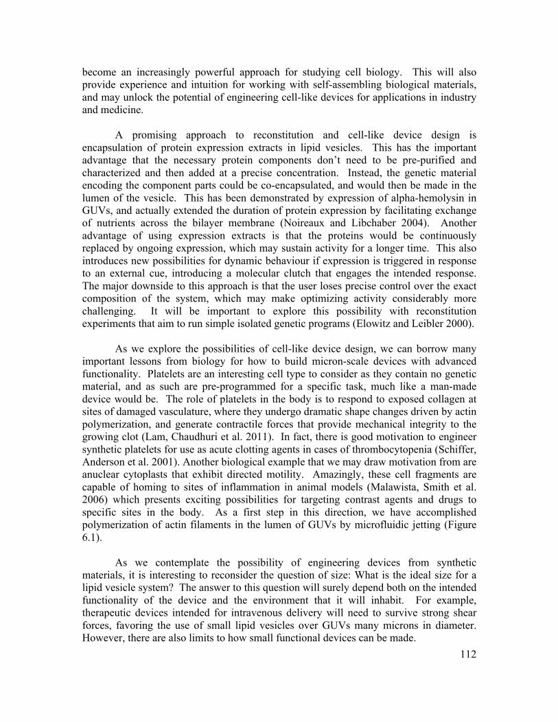
112
become an increasingly powerful approach for studying cell biology. This will also provide experience and intuition for working with self-assembling biological materials, and may unlock the potential of engineering cell-like devices for applications in industry and medicine.
A promising approach to reconstitution and cell-like device design is
encapsulation of protein expression extracts in lipid vesicles. This has the important advantage that the necessary protein components don’t need to be pre-purified and characterized and then added at a precise concentration. Instead, the genetic material encoding the component parts could be co-encapsulated, and would then be made in the lumen of the vesicle. This has been demonstrated by expression of alpha-hemolysin in GUVs, and actually extended the duration of protein expression by facilitating exchange of nutrients across the bilayer membrane (Noireaux and Libchaber 2004). Another advantage of using expression extracts is that the proteins would be continuously replaced by ongoing expression, which may sustain activity for a longer time. This also introduces new possibilities for dynamic behaviour if expression is triggered in response to an external cue, introducing a molecular clutch that engages the intended response. The major downside to this approach is that the user loses precise control over the exact composition of the system, which may make optimizing activity considerably more challenging. It will be important to explore this possibility with reconstitution experiments that aim to run simple isolated genetic programs (Elowitz and Leibler 2000).
As we explore the possibilities of cell-like device design, we can borrow many important lessons from biology for how to build micron-scale devices with advanced functionality. Platelets are an interesting cell type to consider as they contain no genetic material, and as such are pre-programmed for a specific task, much like a man-made device would be. The role of platelets in the body is to respond to exposed collagen at sites of damaged vasculature, where they undergo dramatic shape changes driven by actin polymerization, and generate contractile forces that provide mechanical integrity to the growing clot (Lam, Chaudhuri et al. 2011). In fact, there is good motivation to engineer synthetic platelets for use as acute clotting agents in cases of thrombocytopenia (Schiffer, Anderson et al. 2001). Another biological example that we may draw motivation from are anuclear cytoplasts that exhibit directed motility. Amazingly, these cell fragments are capable of homing to sites of inflammation in animal models (Malawista, Smith et al. 2006) which presents exciting possibilities for targeting contrast agents and drugs to specific sites in the body. As a first step in this direction, we have accomplished polymerization of actin filaments in the lumen of GUVs by microfluidic jetting (Figure 6.1). As we contemplate the possibility of engineering devices from synthetic materials, it is interesting to reconsider the question of size: What is the ideal size for a lipid vesicle system? The answer to this question will surely depend both on the intended functionality of the device and the environment that it will inhabit. For example, therapeutic devices intended for intravenous delivery will need to survive strong shear forces, favoring the use of small lipid vesicles over GUVs many microns in diameter. However, there are also limits to how small functional devices can be made.
113
Figure 6.1 (a) Encapsulation of monomeric actin (red) and fascin (green) into GUVs by microfluidic jetting. (b) Actin polymerization within the vesicle yielded a crosslinked network of filaments, which we visualized by confocal microscopy. Scale bar, 50 µm.
For living cells, the smallest conceivable (and observed) size is ~ 200 nm, and this is imposed by the volume required for the minimal genome and the corresponding replication machinery (Knoll 1999). Non-living devices, which don’t require any genetic material or replication machinery, are freed from this requirement, and we can consider the smallest size to be imposed by the stability of the lipid vesicles compartment. Lipid vesicles are stable above a minimal diameter of ~ 20 nm, due to the balance between the line tension of the exposed ‘edge’ that would result if the vesicle were to unfold into a planar sheet, and the energy required to bend the membrane into the highly curved configuration of a spherical surface (Fromherz 1983). However, in such a highly confined environment, a single molecule has the concentration of ~ 400 mM, and it would likely be prohibitive to engineer complicated biochemical reactions to occur under such extreme conditions. Thus, it is likely that, similar to the case for living cells, the minimum size for cell-inspired devices will be imposed by the requirement of encapsulating sufficient materials to support the intended action.
For devices designed to accomplish shape change and motility, driven by the
polymerization forces of encapsulated polymers and motors, another important consideration is the deformability of the lipid membrane. Lipid vesicles with diameters ~ 20 nm are highly tensed, and allow almost no shape change. The minimal size and design for dramatic shape change may in fact be exemplified by platelets, which are oblate discoids ~ 2 x 0.5 um in size, and contain actin at 100’s mM (Pollard, Fujiwara et al. 1977). An interesting challenge will be to reconstitute directed actin polymerization at such extreme concentrations, whereas dendritic actin network formation has typically been reconstituted at ~ 10 µM in µL volumes.
114
Looking forward, there are many challenges for translating discoveries from reconstitution experiments into functional devices. The primary challenge derives from the complications of working with biological materials which typically need to be purified from primary sources, or expressed in bacterial or cell-free systems, and carefully characterized prior to use, a process that can require considerable background knowledge and experience. This challenge is compounded when we consider assembling complex devices that will require simultaneous use of many different materials. In the near future, this work will benefit greatly from collaborative centers, such as the recent NIH initiative for nano-medicine which funded collaborative research projects in multiple NanoMedicine Development Centers. Increasingly, biomaterials are commercially available (Avanti, Cytoskeleton) and this will be important for making a wide range of biological materials easily accessible for testing different design ideas. As the list of molecular activities that can be reconstituted in vitro from purified components grows, and the community surpasses a critical mass, it would be beneficial to establish a database of standardized parts, core assays and technologies, similar to the resource offered by the BioBricks Foundation that has emerged for genetic engineering (Smolke 2009). Encapsulation introduces a number of new challenges for reconstitution and device design. The technical challenge of encapsulating macromolecular components in lipid vesicles with simultaneous control of membrane properties is significant. Furthermore, functionality of cell-like devices will rely on transmembrane proteins, for activation by external signals, and other transport activities, such as exocytosis or secretion for controlled release. Currently, there are relatively few examples of reconstitution with transmembrane proteins; however, new facilities for expressing and purifying transmembrane proteins will help bridge this gap (e.g. MPEC, UCSF). A final consideration that will be important as we consider translating basic research discoveries into viable applications, will be throughput of the manufacturing process. A humbling exercise is to consider that the number of platelets in a healthy individual are measured in the 100’s of millions per milliliter. 6.5 Outlook The possibilities of cell-inspired design are only beginning to emerge. Currently, we aim to reconstitute biological function in order to learn how these systems function in their physiologic setting. But this experience also enables us to apply these biological materials to solve important problems in energy and medicine. It is interesting to consider where this pursuit may take us. Will we continue to work with natural materials purified from primary sources, or will we increasingly rely on engineered materials with enhanced robustness, modularity and predictability? What will be the limits of complexity that can be engineered from the bottom up? The minimal genome has recently been estimated at ~ 400 genes (Glass, Assad-Garcia et al. 2006), which encodes the hundreds of proteins necessary for metabolism, growth, replication and division. In stark contrast, the most complex reconstitution is currently 17 proteins (Ohya, Miaczynska et al. 2009). Will we ever be able to build systems with the complexity required to sustain life? If so, at what level of complexity will our intuition fail to keep
115
up with the overwhelming interdependency and non-linearity of the system behavior. Will new theoretical models, benchmarked against in vitro reconstitution experiments, provide a means to predict the emergent behavior of a system of complex components and boundary conditions? Analogous to predicting protein structure ab initio from the sequence of amino acids (ie. protein folding), this will provide be a powerful tool for designing new generations of cell-like devices. Indeed, it is an exciting time in this field, and I hope my contributions will provide useful ideas and tools for those who follow in this work.
116
References Abercrombie, M. (1980). "CROONIAN LECTURE, 1978 - CRAWLING MOVEMENT OF METAZOAN CELLS." Proceedings of the Royal Society of London Series B-Biological Sciences 207(1167): 129-&.
Akin, O. and R. D. Mullins (2008). "Capping protein increases the rate of actin-based motility by promoting filament nucleation by the Arp2/3 complex." Cell 133(5): 841-851.
Altschuler, S. J., S. B. Angenent, et al. (2008). "On the spontaneous emergence of cell polarity." Nature 454(7206): 886-U841.
Angelova, M. I. and D. S. Dimitrov (1986). "LIPOSOME ELECTROFORMATION." Faraday Discussions 81(81): 303-+.
Anglin, T. C. and J. C. Conboy (2009). "Kinetics and Thermodynamics of Flip-Flop in Binary Phospholipid Membranes Measured by Sum-Frequency Vibrational Spectroscopy." Biochemistry 48(43): 10220-10234.
Anno, J. N. (1977). The mechanics of liquid jets. Lexington, Massachusetts, Lexington Books.
Antonny, B. (2006). "Membrane deformation by protein coats." Current Opinion in Cell Biology 18(4): 386-394.
Atencia, J. and D. J. Beebe (2005). "Controlled microfluidic interfaces." Nature 437(7059): 648-655.
Atilgan, E., D. Wirtz, et al. (2006). "Mechanics and dynamics of actin-driven thin membrane protrusions." Biophysical Journal 90(1): 65-76.
Bar-Ziv, R., E. Moses, et al. (1998). "Dynamic excitations in membranes induced by optical tweezers." Biophysical Journal 75(1): 294-320.
Bayley, H., B. Cronin, et al. (2008). "Droplet interface bilayers." Molecular Biosystems 4(12): 1191-1208.
Bernheim-Groswasser, A., S. Wiesner, et al. (2002). "The dynamics of actin-based motility depend on surface parameters." Nature 417(6886): 308-311.
Block, J., T. E. B. Stradal, et al. (2008). "Filopodia formation induced by active mDia2/Drf3." Journal of Microscopy-Oxford 231(3): 506-517.
Boal, D. (2002). Mechanics of the Cell. Cambridge, Cambridge University Press.
117
Bogy, D. B. and F. E. Talke (1984). "EXPERIMENTAL AND THEORETICAL-STUDY OF WAVE-PROPAGATION PHENOMENA IN DROP-ON-DEMAND INK JET DEVICES." Ibm Journal of Research and Development 28(3): 314-321.
Brakke, K. (1992). "The surface evolver." Experimental Mathematics 1(2): 141-165.
Bucher, P., A. Fischer, et al. (1998). "Giant vesicles as biochemical compartments: The use of microinjection techniques." Langmuir 14(10): 2712-2721.
Chan, Y. H. M. and S. G. Boxer (2007). "Model membrane systems and their applications." Current Opinion in Chemical Biology 11(6): 581-587.
Chaudhuri, O., S. H. Parekh, et al. (2007). "Reversible stress softening of actin networks." Nature 445(7125): 295-298.
Chen, I. A., R. W. Roberts, et al. (2004). "The emergence of competition between model protocells." Science 305(5689): 1474-1476.
Chen, Y., B. C. Lagerholm, et al. (2006). "Methods to measure the lateral diffusion of membrane lipids and proteins." Methods 39(2): 147-153.
Chernomordik, L. V. and M. M. Kozlov (2008). "Mechanics of membrane fusion." Nat Struct Mol Biol 15(7): 675-683.
Claessens, M., R. Tharmann, et al. (2006). "Microstructure and viscoelasticity of confined serniflexible polymer networks." Nature Physics 2(3): 186-189.
Co, C., D. T. Wong, et al. (2007). "Mechanism of actin network attachment to moving membranes: Barbed end capture by N-WASP WH2 domains." Cell 128(5): 901-913.
Colletier, J.-P., B. Chaize, et al. (2002). "Protein encapsulation in liposomes: Efficiency depends on interactions between protein and phospholipid bilayer." BMC Biotechnology 2(9 Cited June 24, 2002).
Collins, M. D. and S. L. Keller (2008). "Tuning lipid mixtures to induce or suppress domain formation across leaflets of unsupported asymmetric bilayers." Proceedings of the National Academy of Sciences of the United States of America 105(1): 124-128.
Connell, E., A. Giniatullina, et al. (2008). "Cross-linking of phospholipid membranes is a conserved property of calcium-sensitive synaptotagmins." Journal of Molecular Biology 380(1): 42-50.
Crocker, J. C. and D. G. Grier (1996). "Methods of digital video microscopy for colloidal studies." Journal of Colloid and Interface Science 179(1): 298-310.
Dabiri, J. O. and M. Gharib (2004). "Fluid entrainment by isolated vortex rings." Journal of Fluid Mechanics 511: 311-331.
118
Daga, R. R., A. Yonetani, et al. (2006). "Asymmetric microtubule pushing forces in nuclear centering." Current Biology 16(15): 1544-1550.
Daleke, D. L. and J. V. Lyles (2000). "Identification and purification of aminophospholipid flippases." Biochimica Et Biophysica Acta-Molecular and Cell Biology of Lipids 1486(1): 108-127.
Derenyi, I., F. Julicher, et al. (2002). "Formation and interaction of membrane tubes." Physical Review Letters 88(23).
Deuling, H. J. and W. Helfrich (1976). "Red blood cell shapes as explained on the basis of curvature elasticity." Biophysical Journal 16(8): 861-868.
Di Paolo, G. and P. De Camilli (2006). "Phosphoinositides in cell regulation and membrane dynamics." Nature 443(7112): 651-657.
Dobereiner, H. G., G. Gompper, et al. (2003). "Advanced flicker spectroscopy of fluid membranes." Physical Review Letters 91(4).
Douglass, A. D. and R. D. Vale (2005). "Single-molecule microscopy reveals plasma membrane microdomains created by protein-protein networks that exclude or trap signaling molecules in T cells." Cell 121(6): 937-950.
Dumont, S. and T. J. Mitchison (2009). "Compression Regulates Mitotic Spindle Length by a Mechanochemical Switch at the Poles." Current Biology 19(13): 1086-1095.
Dupuy, A. D. and D. M. Engelman (2008). "Protein area occupancy at the center of the red blood cell membrane." Proceedings of the National Academy of Sciences 105(8): 2848-2852.
Duwe, H. P., J. Kaes, et al. (1990). "BENDING ELASTIC-MODULI OF LIPID BILAYERS - MODULATION BY SOLUTES." Journal De Physique 51(10): 945-962.
Eggert, U. S., T. J. Mitchison, et al. (2006). "Animal cytokinesis: From parts list to mechanisms." Annual Review of Biochemistry 75: 543-566.
Egile, C., T. P. Loisel, et al. (1999). "Activation of the CDC42 effector N-WASP by the Shigella flexneri IcsA protein promotes actin nucleation by Arp2/3 complex and bacterial actin-based motility." Journal of Cell Biology 146(6): 1319-1332.
Elowitz, M. B. and S. Leibler (2000). "A synthetic oscillatory network of transcriptional regulators." Nature 403(6767): 335-338.
Engelman, D. M. (2005). "Membranes are more mosaic than fluid." Nature 438(7068): 578-580.
Evans, E. and W. Rawicz (1990). "Entropy-driven tension and bending elasticity in condensed-fluid membranes." Physical Review Letters 64(17): 2094.
119
Evans, E. A. and R. Waugh (1977). "OSMOTIC CORRECTION TO ELASTIC AREA COMPRESSIBILITY MEASUREMENTS ON RED-CELL MEMBRANE." Biophysical Journal 20(3): 307-313.
Fadok, V. A., D. R. Voelker, et al. (1992). "EXPOSURE OF PHOSPHATIDYLSERINE ON THE SURFACE OF APOPTOTIC LYMPHOCYTES TRIGGERS SPECIFIC RECOGNITION AND REMOVAL BY MACROPHAGES." Journal of Immunology 148(7): 2207-2216.
Faivre-Moskalenko, C. and M. Dogterom (2002). "Dynamics of microtubule asters in microfabricated chambers: The role of catastrophes." Proceedings of the National Academy of Sciences of the United States of America 99(26): 16788-16793.
Faix, J., D. Breitsprecher, et al. (2009). "Filopodia: Complex models for simple rods." International Journal of Biochemistry & Cell Biology 41(8-9): 1656-1664.
Faix, J. and K. Rottner (2006). "The making of filopodia." Current Opinion in Cell Biology 18(1): 18-25.
Fletcher, D. A. and R. D. Mullins (2010). "Cell mechanics and the cytoskeleton." Nature 463(7280): 485-492.
Footer, M. J., J. W. J. Kerssemakers, et al. (2007). "Direct measurement of force generation by actin filament polymerization using an optical trap." Proceedings of the National Academy of Sciences of the United States of America 104(7): 2181-2186.
Fromherz, P. (1983). "LIPID-VESICLE STRUCTURE - SIZE CONTROL BY EDGE-ACTIVE AGENTS." Chemical Physics Letters 94(3): 259-266.
Fujii, T., A. H. Iwane, et al. (2010). "Direct visualization of secondary structures of F-actin by electron cryomicroscopy." Nature 467(7316): 724-U117.
Funakoshi, K., H. Suzuki, et al. (2006). "Lipid bilayer formation by contacting monolayers in a microfluidic device for membrane protein analysis." Analytical Chemistry 78(24): 8169-8174.
Funakoshi, K., H. Suzuki, et al. (2007). "Formation of giant lipid vesiclelike compartments from a planar lipid membrane by a pulsed jet flow." Journal of the American Chemical Society 129: 12608-+.
Fygenson, D. K., M. Elbaum, et al. (1997). "Microtubules and vesicles under controlled tension." Physical Review E 55(1): 850-859.
Garner, E. C., C. S. Campbell, et al. (2007). "Reconstitution of DNA segregation driven by assembly of a prokaryotic actin homolog." Science 315(5816): 1270-1274.
120
Gharib, M., E. Rambod, et al. (1998). "A universal time scale for vortex ring formation." Journal of Fluid Mechanics 360: 121-140.
Giardini, P. A., D. A. Fletcher, et al. (2003). "Compression forces generated by actin comet tails on lipid vesicles." Proceedings of the National Academy of Sciences of the United States of America 100(11): 6493-6498.
Girard, P., J. Pecreaux, et al. (2004). "A new method for the reconstitution of membrane proteins into giant unilamellar vesicles." Biophysical Journal 87(1): 419-429.
Glass, J. I., N. Assad-Garcia, et al. (2006). "Essential genes of a minimal bacterium." Proceedings of the National Academy of Sciences of the United States of America 103(2): 425-430.
Goldberg, M., R. Langer, et al. (2007). "Nanostructured materials for applications in drug delivery and tissue engineering." Journal of Biomaterials Science-Polymer Edition 18(3): 241-268.
Gregoretti, I. V., G. Margolin, et al. (2006). "Insights into cytoskeletal behavior from computational modeling of dynamic microtubules in a cell-like environment." Journal of Cell Science 119(22): 4781-4788.
Groffen, A. J., S. Martens, et al. (2010). "Doc2b Is a High-Affinity Ca2+ Sensor for Spontaneous Neurotransmitter Release." Science 327(5973): 1614-1618.
Groves, J. T. and S. G. Boxer (1995). "Electric field-induced concentration gradients in planar supported bilayers." Biophysical Journal 69(5): 1972-1975.
Groves, J. T. and S. G. Boxer (2002). "Micropattern formation in supported lipid membranes." Accounts of Chemical Research 35(3): 149-157.
Gunther, A. and K. F. Jensen (2006). "Multiphase microfluidics: from flow characteristics to chemical and materials synthesis." Lab on a Chip 6(12): 1487-1503.
Gupton, S. L. and F. B. Gertler (2007). "Filopodia: The Fingers That Do the Walking." Sci. STKE 2007(400): re5-.
Hanczyc, M. M., S. M. Fujikawa, et al. (2003). "Experimental models of primitive cellular compartments: Encapsulation, growth, and division." Science 302(5645): 618-622.
Hannun, Y. A. and L. M. Obeid (2008). "Principles of bioactive lipid signalling: lessons from sphingolipids." Nature Reviews Molecular Cell Biology 9(2): 139-150.
Haviv, L., Y. Brill-Karniely, et al. (2006). "Reconstitution of the transition from lamellipodium to filopodium in a membrane-free system." Proceedings of the National Academy of Sciences of the United States of America 103(13): 4906-4911.
121
He, M. Y. (2008). "Cell-free protein synthesis: applications in proteomics and biotechnology." New Biotechnology 25(2-3): 126-132.
Helfrich, W. (1973). "ELASTIC PROPERTIES OF LIPID BILAYERS - THEORY AND POSSIBLE EXPERIMENTS." Zeitschrift Fur Naturforschung C-a Journal of Biosciences C 28(11-1): 693-703.
Hill, T. L. and M. W. Kirschner (1982). "BIOENERGETICS AND KINETICS OF MICROTUBULE AND ACTIN FILAMENT ASSEMBLY-DISASSEMBLY." International Review of Cytology-a Survey of Cell Biology 78: 1-125.
Holden, M. A., D. Needham, et al. (2007). "Functional bionetworks from nanoliter water droplets." Journal of the American Chemical Society 129(27): 8650-8655.
Holmes, K. C., D. Popp, et al. (1990). "ATOMIC MODEL OF THE ACTIN FILAMENT." Nature 347(6288): 44-49.
Holy, T. E., M. Dogterom, et al. (1997). "Assembly and positioning of microtubule asters in microfabricated chambers." Proceedings of the National Academy of Sciences of the United States of America 94(12): 6228-6231.
Homan, R. and H. J. Pownall (1988). "Transbilayer diffusion of phospholipids: dependence on headgroup structure and acyl chain length." Biochimica et Biophysica Acta (BBA) - Biomembranes 938(2): 155-166.
Honda, M., K. Takiguchi, et al. (1999). "Morphogenesis of liposomes encapsulating actin depends on the type of actin-crosslinking." Journal of Molecular Biology 287(2): 293-300.
Hope, M. J., M. B. Bally, et al. (1985). "PRODUCTION OF LARGE UNILAMELLAR VESICLES BY A RAPID EXTRUSION PROCEDURE - CHARACTERIZATION OF SIZE DISTRIBUTION, TRAPPED VOLUME AND ABILITY TO MAINTAIN A MEMBRANE-POTENTIAL." Biochimica Et Biophysica Acta 812(1): 55-65.
Hosokawa, K., T. Fujii, et al. (1999). "Handling of picoliter liquid samples in a poly(dimethylsiloxane)-based microfluidic device." Analytical Chemistry 71(20): 4781-4785.
Howard, J. (2001). Mechanics of Motor Proteins and the Cytoskeleton. Sunderland, Sinauer Associates, Inc.
Howell, A. S., N. S. Savage, et al. (2009). "Singularity in Polarization: Rewiring Yeast Cells to Make Two Buds." Cell 139(4): 731-743.
Hsiung, F., F. A. Ramirez-Weber, et al. (2005). "Dependence of Drosophila wing imaginal disc cytonemes on decapentaplegic." Nature 437(7058): 560-563.
122
Huang, C. H. (1969). "STUDIES ON PHOSPHATIDYLCHOLINE VESICLES . FORMATION AND PHYSICAL CHARACTERISTICS." Biochemistry 8(1): 344-&.
Hui, E. F., C. P. Johnson, et al. (2009). "Synaptotagmin-Mediated Bending of the Target Membrane Is a Critical Step in Ca2+-Regulated Fusion." Cell 138(4): 709-721.
Hwang, W. L., M. Chen, et al. (2008). "Asymmetric droplet interface bilayers." Journal of the American Chemical Society 130(18): 5878-+.
Ipsen, J. H., G. Karlstrom, et al. (1987). "PHASE-EQUILIBRIA IN THE PHOSPHATIDYLCHOLINE-CHOLESTEROL SYSTEM." Biochimica Et Biophysica Acta 905(1): 162-172.
Isambert, H., P. Venier, et al. (1995). "FLEXIBILITY OF ACTIN-FILAMENTS DERIVED FROM THERMAL FLUCTUATIONS - EFFECT OF BOUND NUCLEOTIDE, PHALLOIDIN, AND MUSCLE REGULATORY PROTEINS." Journal of Biological Chemistry 270(19): 11437-11444.
Jacobson, K., Z. Rajfur, et al. (2008). "Chromophore-assisted laser inactivation in cell biology." Trends in Cell Biology 18(9): 443-450.
Jahn, R. and R. H. Scheller (2006). "SNAREs [mdash] engines for membrane fusion." Nat Rev Mol Cell Biol 7(9): 631-643.
Jesorka, A., M. Markstrom, et al. (2005). "Controlled hydrogel formation in the internal compartment of giant unilamellar vesicles." Journal of Physical Chemistry B 109(31): 14759-14763.
Kabsch, W., H. G. Mannherz, et al. (1990). "ATOMIC-STRUCTURE OF THE ACTIN - DNASE-I COMPLEX." Nature 347(6288): 37-44.
Kahya, N., E. I. Pecheur, et al. (2001). "Reconstitution of membrane proteins into giant unilamellar vesicles via peptide-induced fusion." Biophysical Journal 81(3): 1464-1474.
Karlsson, M., K. Nolkrantz, et al. (2000). "Electroinjection of colloid particles and biopolymers into single unilamellar liposomes and cells for bioanalytical applications." Analytical Chemistry 72(23): 5857-5862.
Kelly, B. T., J. C. Baret, et al. (2007). "Miniaturizing chemistry and biology in microdroplets." Chemical Communications(18): 1773-1788.
Kholodenko, B. N., J. B. Hoek, et al. (2000). "Why cytoplasmic signalling proteins should be recruited to cell membranes." Trends in Cell Biology 10(5): 173-178.
Kida, Y., F. Morimoto, et al. (2007). "Two translocating hydrophilic segments of a nascent chain span the ER membrane during multispanning protein topogenesis." The Journal of Cell Biology 179(7): 1441-1452.
123
Knoll, A. (1999). Size Limits of Very Small Microorganisms. Washington, DC, National Academy Press.
Kornberg, A. (1960). "BIOLOGIC SYNTHESIS OF DEOXYRIBONUCLEIC ACID." Science 131(3412): 1503-1508.
Koster, G., A. Cacciuto, et al. (2005). "Force barriers for membrane tube formation." Physical Review Letters 94(6).
Koster, G., M. VanDuijn, et al. (2003). "Membrane tube formation from giant vesicles by dynamic association of motor proteins." Proceedings of the National Academy of Sciences of the United States of America 100: 15583-15588.
Kozlov, M. M. and A. Mogilner (2007). "Model of polarization and bistability of cell fragments." Biophysical Journal 93(11): 3811-3819.
Krogh, A., B. Larsson, et al. (2001). "Predicting transmembrane protein topology with a hidden markov model: application to complete genomes." Journal of Molecular Biology 305(3): 567-580.
Lam, W. A., O. Chaudhuri, et al. (2011). "Mechanics and contraction dynamics of single platelets and implications for clot stiffening." Nat Mater 10(1): 61-66.
Lammermann, T., B. L. Bader, et al. (2008). "Rapid leukocyte migration by integrin-independent flowing and squeezing." Nature 453(7191): 51-+.
Lasic, D. D. and D. Papahadjopoulos (1995). "LIPOSOMES REVISITED." Science 267(5202): 1275-1276.
LaVan, D. A., T. McGuire, et al. (2003). "Small-scale systems for in vivo drug delivery." Nature Biotechnology 21(10): 1184-1191.
Lecuit, T. and P. F. Lenne (2007). "Cell surface mechanics and the control of cell shape, tissue patterns and morphogenesis." Nature Reviews Molecular Cell Biology 8(8): 633-644.
Lee, K., J. L. Gallop, et al. (2010). "Self-Assembly of Filopodia-Like Structures on Supported Lipid Bilayers." Science 329(5997): 1341-1345.
Li, T. H., J. C. Stachowiak, et al. (2009). "MIXING SOLUTIONS IN INKJET FORMED VESICLES." Methods in Enzymology Liposomes, Pt G 465: 75-94.
Liu, A. P. and D. A. Fletcher (2006). "Actin polymerization serves as a membrane domain switch in model lipid bilayers." Biophysical Journal 91(11): 4064-4070.
Liu, A. P. and D. A. Fletcher (2009). "Biology under construction: in vitro reconstitution of cellular function." Nature Reviews Molecular Cell Biology 10(9): 644-650.
124
Liu, A. P., D. L. Richmond, et al. (2008). "Membrane-induced bundling of actin filaments." Nature Physics 4(10): 789-793.
Loisel, T. P., R. Boujemaa, et al. (1999). "Reconstitution of actin-based motility of Listeria and Shigella using pure proteins." Nature 401(6753): 613-616.
Lorenz, H., D. W. Hailey, et al. (2006). "The fluorescence protease protection (FPP) assay to determine protein localization and membrane topology." Nature Protocols 1(1): 276-279.
Malawista, S. E., E. O. Smith, et al. (2006). "Cryopreservable neutrophil surrogates: Granule-poor, motile cytoplasts from polymorphonuclear leukocytes home to inflammatory lesions in vivo." Cell Motility and the Cytoskeleton 63(5): 254-257.
Mansy, S. S., J. P. Schrum, et al. (2008). "Template-directed synthesis of a genetic polymer in a model protocell." Nature 454(7200): 122-U110.
Martens, S., M. M. Kozlov, et al. (2007). "How synaptotagmin promotes membrane fusion." Science 316(5828): 1205-1208.
Martens, S. and H. T. McMahon (2008). "Mechanisms of membrane fusion: disparate players and common principles." Nature Reviews Molecular Cell Biology 9(7): 543-556.
Mattila, P. K., A. Pykalainen, et al. (2007). "Missing-in-metastasis and IRSp53 deform PI(4,5)P-2-rich membranes by an inverse BAR domain-like mechanism." Journal of Cell Biology 176(7): 953-964.
Maxworthy, T. (1972). "STRUCTURE AND STABILITY OF VORTEX RINGS." Journal of Fluid Mechanics 51(JAN11): 15-&.
McMahon, H. T. and J. L. Gallop (2005). "Membrane curvature and mechanisms of dynamic cell membrane remodelling." Nature 438(7068): 590-596.
Mejillano, M. R., S. Kojima, et al. (2004). "Lamellipodial versus filopodial mode of the actin nanomachinery: Pivotal role of the filament barbed end." Cell 118(3): 363-373.
Minc, N., D. Burgess, et al. (2011). "Influence of Cell Geometry on Division-Plane Positioning." Cell 144(3): 414-426.
Miyata, H., S. Nishiyama, et al. (1999). "Protrusive growth from giant liposomes driven by actin polymerization." Proceedings of the National Academy of Sciences of the United States of America 96(5): 2048-2053.
Mogilner, A. and B. Rubinstein (2005). "The physics of filopodial protrusion." Biophysical Journal 89(2): 782-795.
Mongiu, A. K., E. L. Weitzke, et al. (2007). "Kinetic-structural analysis of neuronal growth cone veil motility." Journal of Cell Science 120(6): 1113-1125.
125
Mossman, K. D., G. Campi, et al. (2005). "Altered TCR signaling from geometrically repatterned immunological synapses." Science 310(5751): 1191-1193.
Mullins, R. D., J. A. Heuser, et al. (1998). "The interaction of Arp2/3 complex with actin: Nucleation, high affinity pointed end capping, and formation of branching networks of filaments." Proceedings of the National Academy of Sciences of the United States of America 95(11): 6181-6186.
Nagy, S., B. L. Ricca, et al. (2008). "A myosin motor that selects bundled actin for motility." Proceedings of the National Academy of Sciences of the United States of America 105(28): 9616-9620.
Noireaux, V. and A. Libchaber (2004). "A vesicle bioreactor as a step toward an artificial cell assembly." Proceedings of the National Academy of Sciences of the United States of America 101(51): 17669-17674.
Noireaux, V., Y. T. Maeda, et al. (2011). "Development of an artificial cell, from self-organization to computation and self-reproduction." Proceedings of the National Academy of Sciences 108(9): 3473-3480.
Nye, J. A. and J. T. Groves (2008). "Kinetic control of histidine-tagged protein surface density on supported lipid bilayers." Langmuir 24(8): 4145-4149.
Ohya, T., M. Miaczynska, et al. (2009). "Reconstitution of Rab- and SNARE-dependent membrane fusion by synthetic endosomes." Nature 459(7250): 1091-U1077.
Olbrich, K., W. Rawicz, et al. (2000). "Water permeability and mechanical strength of polyunsaturated lipid bilayers." Biophysical Journal 79(1): 321-327.
Olson, F., C. A. Hunt, et al. (1979). "PREPARATION OF LIPOSOMES OF DEFINED SIZE DISTRIBUTION BY EXTRUSION THROUGH POLYCARBONATE MEMBRANES." Biochimica Et Biophysica Acta 557(1): 9-23.
Onfelt, B., S. Nedvetzki, et al. (2006). "Structurally distinct membrane nanotubes between human macrophages support long-distance vesicular traffic or surfing of bacteria." Journal of Immunology 177(12): 8476-8483.
Osawa, M., D. E. Anderson, et al. (2008). "Reconstitution of contractile FtsZ rings in liposomes." Science 320(5877): 792-794.
Otsuji, M., S. Ishihara, et al. (2007). "A mass conserved reaction-diffusion system captures properties of cell polarity." Plos Computational Biology 3(6): 1040-1054.
Pagano, R. E., O. C. Martin, et al. (1981). "FORMATION OF ASYMMETRIC PHOSPHOLIPID-MEMBRANES VIA SPONTANEOUS TRANSFER OF FLUORESCENT LIPID ANALOGS BETWEEN VESICLE POPULATIONS." Biochemistry 20(17): 4920-4927.
126
Papayannopoulos, V., C. Co, et al. (2005). "A polybasic motif allows N-WASP to act as a sensor of PIP2 density." Molecular Cell 17(2): 181-191.
Parekh, S. H., O. Chaudhuri, et al. (2005). "Loading history determines the velocity of actin-network growth." Nature Cell Biology 7(12): 1219-1223.
Pautot, S., B. J. Frisken, et al. (2003). "Engineering asymmetric vesicles." Proceedings of the National Academy of Sciences of the United States of America 100(19): 10718-10721.
Pautot, S., B. J. Frisken, et al. (2003). "Production of unilamellar vesicles using an inverted emulsion." Langmuir 19(7): 2870-2879.
Peterson, M. A., H. Strey, et al. (1992). "THEORETICAL AND PHASE-CONTRAST MICROSCOPIC EIGENMODE ANALYSIS OF ERYTHROCYTE FLICKER - AMPLITUDES." Journal De Physique Ii 2(5): 1273-1285.
Pinot, M., F. Chesnel, et al. (2009). "Effects of Confinement on the Self-Organization of Microtubules and Motors." Current Biology 19(11): 954-960.
Pollard, T. D., L. Blanchoin, et al. (2000). "MOLECULAR MECHANISMS CONTROLLING ACTIN FILAMENT DYNAMICS IN NONMUSCLE CELLS." Annual Review of Biophysics and Biomolecular Structure 29(1): 545-576.
Pollard, T. D. and G. G. Borisy (2003). "Cellular motility driven by assembly and disassembly of actin filaments." Cell 112(4): 453-465.
Pollard, T. D. and J. A. Cooper (1986). "ACTIN AND ACTIN-BINDING PROTEINS - A CRITICAL-EVALUATION OF MECHANISMS AND FUNCTIONS." Annual Review of Biochemistry 55: 987-1035.
Pollard, T. D. and J. A. Cooper (2009). "Actin, a Central Player in Cell Shape and Movement." Science 326(5957): 1208-1212.
Pollard, T. D., K. Fujiwara, et al. (1977). "CONTRACTILE PROTEINS IN PLATELET ACTIVATION AND CONTRACTION." Annals of the New York Academy of Sciences 283(FEB10): 218-236.
Pontani, L. L., J. van der Gucht, et al. (2009). "Reconstitution of an Actin Cortex Inside a Liposome." Biophysical Journal 96(1): 192-198.
Ponti, A., M. Machacek, et al. (2004). "Two distinct actin networks drive the protrusion of migrating cells." Science 305(5691): 1782-1786.
Powers, T. R., G. Huber, et al. (2002). "Fluid-membrane tethers: Minimal surfaces and elastic boundary layers." Physical Review E 65(4).
127
Prehoda, K. and W. Lim (2002). "How signaling proteins integrate multiple inputs: a comparison of N-WASP and Cdk2." Current Opinion in Cell Biology 14: 149-154.
Pronk, S., P. L. Geissler, et al. (2008). "Limits of filopodium stability." Physical Review Letters 100(25).
Raucher, D. and M. P. Sheetz (1999). "Characteristics of a membrane reservoir buffering membrane tension." Biophysical Journal 77(4): 1992-2002.
Rawicz, W., K. C. Olbrich, et al. (2000). "Effect of Chain Length and Unsaturation on Elasticity of Lipid Bilayers." Biophysical Journal 79(1): 328-339.
Reeves, J. P. and R. M. Dowben (1969). "FORMATION AND PROPERTIES OF THIN-WALLED PHOSPHOLIPID VESICLES." Journal of Cellular Physiology 73(1): 49-&.
Romet-Lemonne, G., M. VanDuijn, et al. (2005). "Three-dimensional control of protein patterning in microfabricated devices." Nano Letters 5(12): 2350-2354.
Rossier, O., D. Cuvelier, et al. (2003). "Giant vesicles under flows: Extrusion and retraction of tubes." Langmuir 19(3): 575-584.
Roux, A., K. Uyhazi, et al. (2006). "GTP-dependent twisting of dynamin implicates constriction and tension in membrane fission." Nature 441(7092): 528-531.
Saffman, P. G. (1970). "VELOCITY OF VISCOUS VORTEX RINGS." Studies in Applied Mathematics 49(4): 371-&.
Schiffer, C. A., K. C. Anderson, et al. (2001). "Platelet transfusion for patients with cancer: Clinical practice guidelines of the American Society of Clinical Oncology." Journal of Clinical Oncology 19(5): 1519-1538.
Schirenbeck, A., R. Arasada, et al. (2005). "Formins and VASPs may co-operate in the formation of filopodia." Biochemical Society Transactions 33: 1256-1259.
Schirenbeck, A., R. Arasada, et al. (2006). "The bundling activity of vasodilator-stimulated phosphoprotein is required for filopodium formation." Proceedings of the National Academy of Sciences of the United States of America 103(20): 7694-7699.
Schmidt, C. F., M. Barmann, et al. (1989). "CHAIN DYNAMICS, MESH SIZE, AND DIFFUSIVE TRANSPORT IN NETWORKS OF POLYMERIZED ACTIN - A QUASIELASTIC LIGHT-SCATTERING AND MICROFLUORESCENCE STUDY." Macromolecules 22(9): 3638-3649.
Schrodinger, E. (1967). What is Life? and Mind and Matter. Cambridge, Cambridge University Press.
Schrum, J. P., T. F. Zhu, et al. (2010). "The Origins of Cellular Life." Cold Spring Harbor Perspectives in Biology 2(9).
128
Sessa, G. and Weissman.G (1970). "INCORPORATION OF LYSOZYME INTO LIPOSOMES - A MODEL FOR STRUCTURE-LINKED LATENCY." Journal of Biological Chemistry 245(13): 3295-&.
Shao, J. Y. and R. M. Hochmuth (1996). "Micropipette suction for measuring piconewton forces of adhesion and tether formation from neutrophil membranes." Biophysical Journal 71(5): 2892-2901.
Shariff, K. and A. Leonard (1992). "VORTEX RINGS." Annual Review of Fluid Mechanics 24: U235-U279.
Shum, H. C., D. Lee, et al. (2008). "Double emulsion templated monodisperse phospholipid vesicles." Langmuir 24(15): 7651-7653.
Shusser, M. and M. Gharib (2000). "Energy and velocity of a forming vortex ring." Physics of Fluids 12(3): 618-621.
Sigal, Y. J., O. A. Quintero, et al. (2007). "Cdc42 and ARP2/3-independent regulation of filopodia by an integral membrane lipid-phosphatase-related protein." Journal of Cell Science 120(2): 340-352.
Simons, K. and M. J. Gerl (2010). "Revitalizing membrane rafts: new tools and insights." Nature Reviews Molecular Cell Biology 11(10): 688-699.
Singer, S. J. and G. L. Nicolson (1972). "FLUID MOSAIC MODEL OF STRUCTURE OF CELL-MEMBRANES." Science 175(4023): 720-&.
Smolke, C. D. (2009). "Building outside of the box: iGEM and the BioBricks Foundation." Nature Biotechnology 27(12): 1099-1102.
Smythe, E. and K. R. Ayscough (2006). "Actin regulation in endocytosis." Journal of Cell Science 119(22): 4589-4598.
Snapper, S. B., F. Takeshima, et al. (2001). "N-WASP deficiency reveals distinct pathways for cell surface projections and microbial actin-based motility." Nature Cell Biology 3(10): 897-904.
Spudich, J. A. and S. Watt (1971). "REGULATION OF RABBIT SKELETAL MUSCLE CONTRACTION .1. BIOCHEMICAL STUDIES OF INTERACTION OF TROPOMYOSIN-TROPONIN COMPLEX WITH ACTIN AND PROTEOLYTIC FRAGMENTS OF MYOSIN." Journal of Biological Chemistry 246(15): 4866-&.
Stachowiak, J. C., C. C. Hayden, et al. (2010). "Steric confinement of proteins on lipid membranes can drive curvature and tubulation." Proceedings of the National Academy of Sciences of the United States of America 107(17): 7781-7786.

129
Stachowiak, J. C., D. L. Richmond, et al. (2009). "Inkjet formation of unilamellar lipid vesicles for cell-like encapsulation." Lab on a Chip 9(14): 2003-2009.
Stachowiak, J. C., D. L. Richmond, et al. (2008). "Unilamellar vesicle formation and encapsulation by microfluidic jetting." Proceedings of the National Academy of Sciences of the United States of America 105(12): 4697-4702.
Stachowiak, J. C., M. G. von Muhlen, et al. (2007). "Piezoelectric control of needle-free transdermal drug delivery." Journal of Controlled Release 124(1-2): 88-97.
Steffen, A., J. Faix, et al. (2006). "Filopodia formation in the absence of functional WAVE- and Arp2/3-complexes." Molecular Biology of the Cell 17(6): 2581-2591.
Sud, M., E. Fahy, et al. (2007). "LMSD: LIPID MAPS structure database." Nucleic Acids Research 35: D527-D532.
Svitkina, T. M. and G. G. Borisy (1999). "Arp2/3 complex and actin depolymerizing factor cofilin in dendritic organization and treadmilling of actin filament array in lamellipodia." Journal of Cell Biology 145(5): 1009-1026.
Svitkina, T. M., E. A. Bulanova, et al. (2003). "Mechanism of filopodia initiation by reorganization of a dendritic network." Journal of Cell Biology 160(3): 409-421.
Szoka, F. and D. Papahadjopoulos (1978). "PROCEDURE FOR PREPARATION OF LIPOSOMES WITH LARGE INTERNAL AQUEOUS SPACE AND HIGH CAPTURE BY REVERSE-PHASE EVAPORATION." Proceedings of the National Academy of Sciences of the United States of America 75(9): 4194-4198.
Takeuchi, S., P. Garstecki, et al. (2005). "An axisymmetric flow-focusing microfluidic device." Advanced Materials 17(8): 1067-+.
Takiguchi, K., A. Yamada, et al. (2008). "Entrapping Desired Amounts of Actin Filaments and Molecular Motor Proteins in Giant Liposomes." Langmuir 24(20): 11323-11326.
Tareste, D., J. Shen, et al. (2008). "SNAREpin/Munc18 promotes adhesion and fusion of large vesicles to giant membranes." Proceedings of the National Academy of Sciences of the United States of America 105(7): 2380-2385.
Taunton, J., B. A. Rowning, et al. (2000). "Actin-dependent propulsion of endosomes and lysosomes by recruitment of N-WASP." Journal of Cell Biology 148(3): 519-530.
Tawfik, D. S. and A. D. Griffiths (1998). "Man-made cell-like compartments for molecular evolution." Nature Biotechnology 16(7): 652-656.
Teh, S. Y., R. Lin, et al. (2008). "Droplet microfluidics." Lab on a Chip 8(2): 198-220.
130
Tolic-Norrelykke, I. M. (2008). "Push-me-pull-you: how microtubules organize the cell interior." European Biophysics Journal with Biophysics Letters 37(7): 1271-1278.
Tolic-Norrelykke, I. M., L. Sacconi, et al. (2005). "Nuclear and division-plane positioning revealed by optical micromanipulation." Current Biology 15(13): 1212-1216.
Tolic-Norrelykke, I. M., L. Sacconi, et al. (2004). "Positioning and elongation of the fission yeast spindle by microtubule-based pushing." Current Biology 14(13): 1181-1186.
Torchilin, V. P. (2005). "Recent advances with liposomes as pharmaceutical carriers." Nature Reviews Drug Discovery 4(2): 145-160.
Tran, P. T., L. Marsh, et al. (2001). "A mechanism for nuclear positioning in fission yeast based on microtubule pushing." Journal of Cell Biology 153(2): 397-411.
Upadhyaya, A., J. R. Chabot, et al. (2003). "Probing polymerization forces by using actin-propelled lipid vesicles." Proceedings of the National Academy of Sciences of the United States of America 100(8): 4521-4526.
Urban, E., S. Jacob, et al. (2010). "Electron tomography reveals unbranched networks of actin filaments in lamellipodia." Nature Cell Biology 12(5): 429-U436.
Utada, A. S., E. Lorenceau, et al. (2005). "Monodisperse double emulsions generated from a microcapillary device." Science 308(5721): 537-541.
van Meer, G., D. R. Voelker, et al. (2008). "Membrane lipids: where they are and how they behave." Nat Rev Mol Cell Biol 9(2): 112-124.
Vanhaesebroeck, B., S. J. Leevers, et al. (2001). "Synthesis and function of 3-phosphorylated inositol lipids." Annual Review of Biochemistry 70: 535-602.
Veatch, S. L. and S. L. Keller (2005). "Seeing spots: Complex phase behavior in simple membranes." Biochimica et Biophysica Acta (BBA) - Molecular Cell Research 1746(3): 172-185.
Verkhovsky, A. B., T. M. Svitkina, et al. (1999). "Self-polarization and directional motility of cytoplasm." Current Biology 9(1): 11-20.
Vignjevic, D., S. Kojima, et al. (2006). "Role of fascin in filopodial protrusion." Journal of Cell Biology 174(6): 863-875.
Vignjevic, D., D. Yarar, et al. (2003). "Formation of filopodia-like bundles in vitro from a dendritic network." Journal of Cell Biology 160(6): 951-962.
Vogel, S. K., I. Raabe, et al. (2007). "Interphase microtubules determine the initial alignment of the mitotic spindle." Current Biology 17(5): 438-444.
131
von Heijne, G. (2006). "Membrane-protein topology." Nat Rev Mol Cell Biol 7(12): 909-918.
Walde, P. (1996). "Enzymatic reactions in liposomes." Current Opinion in Colloid & Interface Science 1(5): 638-644.
Weber, T., B. V. Zemelman, et al. (1998). "SNAREpins: Minimal machinery for membrane fusion." Cell 92(6): 759-772.
Weinbaum, S., J. M. Tarbell, et al. (2007). "The Structure and Function of the Endothelial Glycocalyx Layer." Annual Review of Biomedical Engineering 9(1): 121-167.
Weng, K. C., J. L. Kanter, et al. (2006). "Fluid supported lipid bilayers containing mono sialoganglioside GM1: A QCM-D and FRAP study." Colloids and Surfaces B-Biointerfaces 50(1): 76-84.
Whitelegge, J. P., S. M. Gomez, et al. (2003). Proteomics of membrane proteins. Proteome Characterization and Proteomics. San Diego, Academic Press Inc. 65: 271-307.
Wickner, W. and R. Schekman (2008). "Membrane fusion." Nature Structural & Molecular Biology 15(7): 658-664.
Wiesner, S., E. Helfer, et al. (2003). "A biomimetic motility assay provides insight into the mechanism of actin-based motility." Journal of Cell Biology 160(3): 387-398.
Williams, R., S. G. Peisajovich, et al. (2006). "Amplification of complex gene libraries by emulsion PCR." Nature Methods 3(7): 545-550.
Wollert, T., C. Wunder, et al. (2009). "Membrane scission by the ESCRT-III complex." Nature 458(7235): 172-U172.
Wong, R., I. Hadjiyanni, et al. (2005). "PIP2 Hydrolysis and Calcium Release Are Required for Cytokinesis in Drosophila Spermatocytes." Current Biology 15(15): 1401-1406.
Wood, W., A. Jacinto, et al. (2002). "Wound healing recapitulates morphogenesis in Drosophila embryos." Nature Cell Biology 4(11): 907-912.
Wu, Y., N. Tibrewal, et al. (2006). "Phosphatidylserine recognition by phagocytes: a view to a kill." Trends in Cell Biology 16(4): 189-197.
Yeung, T., B. Ozdamar, et al. (2006). "Lipid metabolism and dynamics during phagocytosis." Current Opinion in Cell Biology 18(4): 429-437.
Related Documents