Case 1 Case 2 Bandwidth capacity Reserved 0 Network links with functions for bandwidth reservation Network links without functions for bandwidth reservation

Welcome message from author
This document is posted to help you gain knowledge. Please leave a comment to let me know what you think about it! Share it to your friends and learn new things together.
Transcript

QOS based Multicast CommunicationsYuko Onoe Hideyuki TokudaNTT Keio UniversityInformation and Communication Systems Laboratories Faculty of Environmental Information1-1 Hikarinooka, Yokosuka city, Japan 239 5322 Endo, Fijisawa city, Japan 252AbstractIn a distributed multimedia integration environ-ment, there is a need for transmission control methodsbased on real-time communication protocols, that pro-vide a relative Quality Of Service (QOS) to allow avariety of receiving capacities for group members andtheir requests and that provide a dynamic QOS to copewith temporary CPU overload and network congestion.Therefore, this study proposes a cooperative con-trol method for end-to-end QOS control at a trans-port layer and for point-to-point control at a networklayer. The former is mainly a set of ow-monitoringand ow-adjusting functions, and the latter a set of ow-control functions. The ow-adjusting functionsprovide in-depth evaluation of (1) the characteristicsof the transmission data, (2) end-to-end network per-formance, and (3) the requirements of receiver appli-cations. The appropriate QOS levels and ow controlmethods are then determined on the basis of the re-sults.1 IntroductionNetwork architectures for multimedia communica-tion must ensure the predictability of communicationprocessing on a network-wide basis by transmittingbulk data, such as multimedia data, e�ciently, whileminimizing communication overhead and delay vari-ations. They must also provide scheduling based on ow priorities to avoid network overload and conges-tion.2 Transmission controls of multicastprotocols for continuous media2.1 Transmission controlsExisting real-time communication protocols pro-vide two types of transmission controls. One is re-source reservation and the other is transmission ratecontrol. The former is for reserving CPU capacity andnetwork bandwidths in advance (RSVP[9], ST-II[8]),while the latter changes the transmission rate dynam-ically according to the ow status (HeiTP[2], RTP[6])to cope with packet arrival delay and packet loss. Themedia scaling technologies described in this paper arebased on transmission rate control.In a widely distributed environment, these twomethods are applied individually or combined to pro-vide more various and exible network services. For
Case 1
Case 2
Bandwidth capacity
Reserved
0
Network links with functions for bandwidth reservation
Network links without functions for bandwidth reservationFigure 1: An example of combining resourceresevation and transmission rate controlexample, resources for only the minimum indispens-able components of transmission ow are reserved anddynamic transmission controls function for the re-maining resources according to the degree of networktra�c. That is, until the amount of tra�c reaches thenetwork bandwidth capacity, more bandwidth than re-served can be used and the tra�c can be shaped inresponse to network load. In the worst case, even re-served bandwidth can be used (Fig. 1: Case 1). Forguarantees of end-to-end service quality when thereare some datalinks or routers which do no supportresource reservation on the routing paths, dynamictransmission controls come into play to connect thereserved networks (Fig. 1: Case 2).2.2 Dynamic transmission control re-sponding to network environmentsToday's transmission control is either uni�ed toprovide a unique QOS to a whole group, or static,where the reservation values, once speci�ed and as-signed, hardly ever change. To overcome these limi-tations, it is important to develop transmission con-trol schemes that provide a relative QOS on heteroge-neous networks to allow a variety of group�memberreceiving capacities and requests and provide a dy-namic QOS to cope with temporal CPU overload andnetwork congestion and application requirements.Our approach to resolve these issues is to implementa cooperative control scheme for an end-to-end QOScontrol at the transport layer and a point-to-point con-

trol scheme at the network layer. More speci�cally, theQOS control's functions at intermediate agents to pro-vide a di�erent QOS for each network, and the owis monitored and, if necessary, adjusted to change theend-to-end QOS depending on the status of the trans-mission. Table 1: An example of QOS levelsSubjects Q1 Q2 Q3AudioSignal L+Rsignals(mono) L�RsignalsFrequency 10�4k Hz 4k�10kHz 10k�20kHzphone level AMbroadcasts FMbroadcastsVoice voiced part silencepartVideo�JPEGNTSC �elds even �elds odd �eldsFrame rate evenframes oddframesDegree high middle lowof variationVideo�MPEGPicture I�frame P�frame B�frameMoreover, to handle QOS in group communica-tions, QOS levels (Table 1) are introduced into groupaddress schemes [2][7]. The QOS levels are speci�edaccording to potential factors, such as network andCPU capacities, and dynamic ones, such as networkand CPU loads, to dynamically form subgroups instatic multicast groups and provide a proper QOS foreach subgroup.2.3 An example of QOS �elds in networkpacketsAs an example of network packet fragmentation andthe speci�cation of QOS �elds, we discuss YUV en-coded video image data 320 x 240 pixels in size. Avideo image captured by a video input board is frag-mented according to MTU (Maximum TransmissionUnit) sizes at network layers and Y and UV dataat regular intervals construct one network packet asshown in Fig. 2. In this example, for temporalresolution the frame rate is speci�ed and for spatialresolution the value for YUV signals is speci�ed inQOS �elds in network packets to simultaneously han-dle multiple QOS factors.
320 pixel
Frame-1 Frame-2 Frame-3
8x8
UV
Y Y
8
8
1 byte
(F1,Y4)
Y Y Y Y Y Y Y
Y Y Y Y Y Y Y Y
Y
UV UV UV
UV
UV
UV UV UV
1 byte x 64 2 byte x 32
Y UV
YUV-1
(Frame-1, YUV-1)(F1,Y2) (F1,Y3)
Y UV4 x 4 2 x 4
32 bytes
x 1200
(F2,Y2) (F2,Y3) (F2,Y4)(F2,Y1)
(F3,Y2) (F3,Y3) (F3,Y4)(F3,Y1)
QOS LEVELNetwork packetization
Video image data
240 pixel
Figure 2: An example of network fragmentationconsidering QOS levels2.4 A method of QOS level speci�cationWe want to regularly change the qualiry of videoimages in order to maximize network e�ciency, so wegive each incoming packet the next number from anarray containing QOS-level assignments.The methodof producing the array uses the relationship wherebyan increase of one in the QOS level corresponds to thereceiving rate being multiplied by a constant factor.Packet receiving rates vary at regular times (theconstant factor 'a') as QOS levels increase and thenumber of received packets of level n receivers is fn,f1 � an�1 = fnThen, when they are assigned as f1 = S, fn = F , n =Q, packet receiving rate variance, a, can be formulizedas a = Q�1rFS
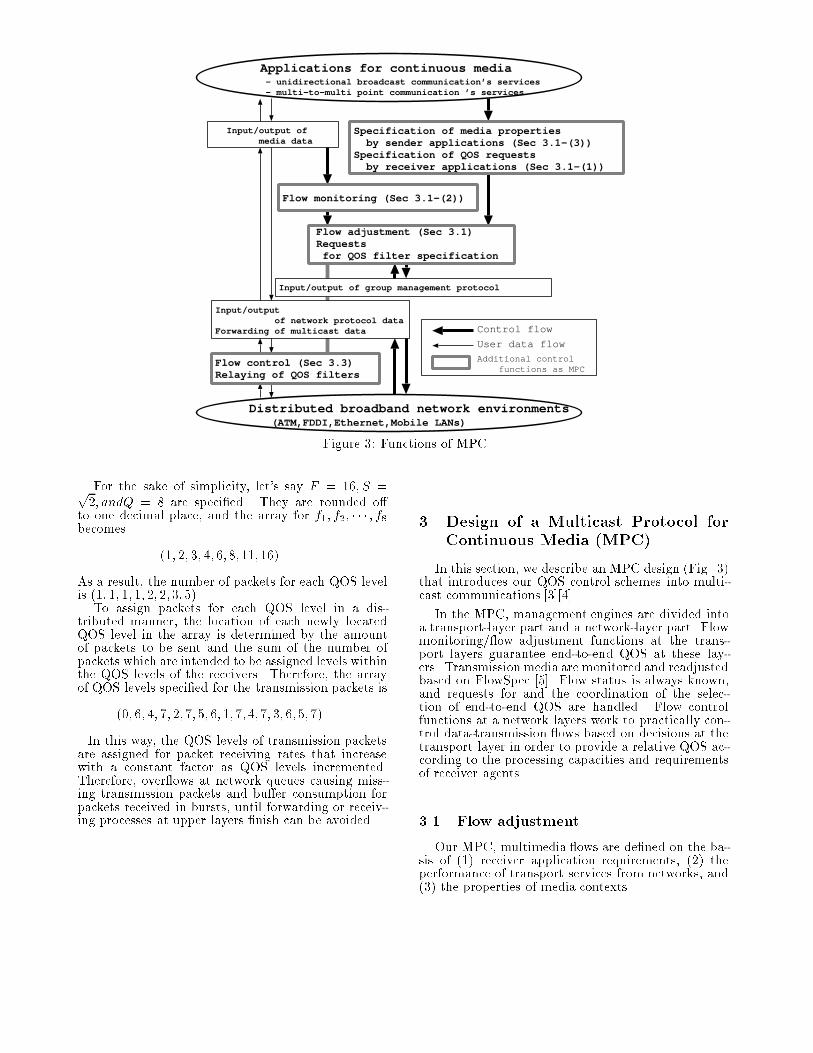
Input/output of group management protocol
Flow monitoring (Sec 3.1-(2))
Specification of media properties by sender applications (Sec 3.1-(3))Specification of QOS requests by receiver applications (Sec 3.1-(1))
Input/output of media data
Flow adjustment (Sec 3.1)Requests for QOS filter specification
Flow control (Sec 3.3)Relaying of QOS filters
Input/output of network protocol dataForwarding of multicast data
- unidirectional broadcast communication’s services - multi-to-multi point communication ’s services
Applications for continuous media
Control flow
User data flow
Additional control functions as MPC
(ATM,FDDI,Ethernet,Mobile LANs)Distributed broadband network environmentsFigure 3: Functions of MPCFor the sake of simplicity, let's say F = 16; S =p2; andQ = 8 are speci�ed. They are rounded o�to one decimal place, and the array for f1; f2; � � � ; f8becomes (1; 2; 3; 4; 6;8;11;16)As a result, the number of packets for each QOS levelis (1; 1; 1; 1; 2; 2;3;5).To assign packets for each QOS level in a dis-tributed manner, the location of each newly locatedQOS level in the array is determined by the amountof packets to be sent and the sum of the number ofpackets which are intended to be assigned levels withinthe QOS levels of the receivers. Therefore, the arrayof QOS levels speci�ed for the transmission packets is(0; 6; 4; 7; 2;7;5; 6; 1;7;4;7; 3; 6;5;7). In this way, the QOS levels of transmission packetsare assigned for packet receiving rates that increasewith a constant factor as QOS levels incremented.Therefore, over ows at network queues causing miss-ing transmission packets and bu�er consumption forpackets received in bursts, until forwarding or receiv-ing processes at upper layers �nish can be avoided.
3 Design of a Multicast Protocol forContinuous Media (MPC)In this section, we describe an MPC design (Fig. 3)that introduces our QOS control schemes into multi-cast communications [3][4].In the MPC, management engines are divided intoa transport-layer part and a network-layer part. Flowmonitoring/ ow adjustment functions at the trans-port layers guarantee end-to-end QOS at these lay-ers. Transmissionmedia are monitored and readjustedbased on FlowSpec [5]. Flow status is always known,and requests for and the coordination of the selec-tion of end-to-end QOS are handled. Flow controlfunctions at a network layers work to practically con-trol data-transmission ows based on decisions at thetransport layer in order to provide a relative QOS ac-cording to the processing capacities and requirementsof receiver agents.3.1 Flow adjustmentOur MPC, multimedia ows are de�ned on the ba-sis of (1) receiver application requirements, (2) theperformance of transport services from networks, and(3) the properties of media contexts.
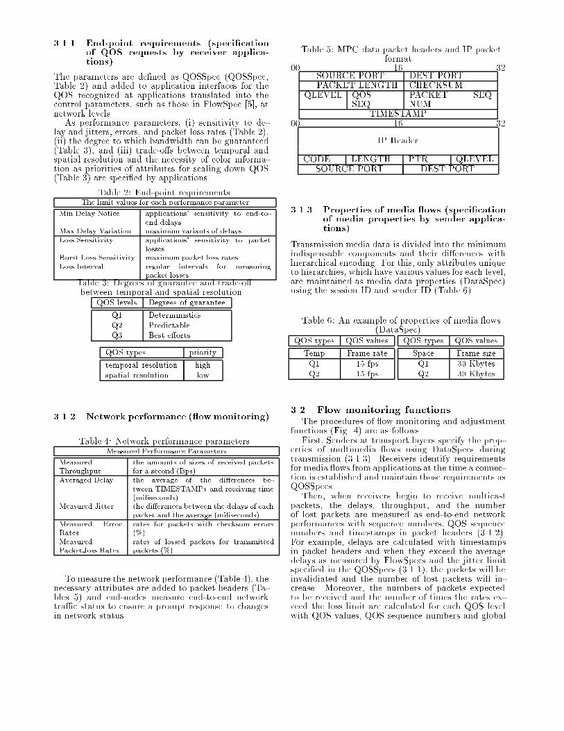
3.1.1 End-point requirements (speci�cationof QOS requests by receiver applica-tions)The parameters are de�ned as QOSSpec (QOSSpec,Table 2) and added to application interfaces for theQOS recognized at applications translated into thecontrol parameters, such as those in FlowSpec [5], atnetwork levels.As performance parameters, (i) sensitivity to de-lay and jitters, errors, and packet loss rates (Table 2),(ii) the degree to which bandwidth can be guaranteed(Table 3), and (iii) trade-o�s between temporal andspatial resolution and the necessity of color informa-tion as priorities of attributes for scaling down QOS(Table 3) are speci�ed by applications.Table 2: End-point requirementsThe limit values for each performance parameterMin Delay Notice applications' sensitivity to end-to-end delaysMax Delay Variation maximum variants of delaysLoss Sensitivity applications' sensitivity to packetlossesBurst Loss Sensitivity maximum packet loss ratesLoss Interval regular intervals for measuringpacket lossesTable 3: Degrees of guarantee and trade-o�between temporal and spatial resolutionQOS levels Degrees of guaranteeQ1 DeterministicsQ2 PredictableQ3 Best e�ortsQOS types prioritytemporal resolution highspatial resolution low3.1.2 Network performance ( ow monitoring)Table 4: Network performance parametersMeasured Performance ParametersMeasuredThroughput the amounts of sizes of received packetsfor a second (Bps)Averaged Delay the average of the di�erences be-tween TIMESTAMPs and receiving time(miliseconds)Measured Jitter the di�erences between the delays of eachpacket and the average (miliseconds)Measured ErrorRates rates for packets with checksum errors(%)MeasuredPacket loss Rates rates of lossed packets for transmittedpackets (%)To measure the network performance (Table 4), thenecessary attributes are added to packet headers (Ta-bles 5) and end-nodes measure end-to-end networktra�c status to ensure a prompt response to changesin network status.
Table 5: MPC data packet headers and IP packetformat00 16 32SOURCE PORT DEST PORTPACKET LENGTH CHECKSUMQLEVEL QOSSEQ PACKET SEQNUMTIMESTAMP00 16 32IP HeaderCODE LENGTH PTR QLEVELSOURCE PORT DEST PORT3.1.3 Properties of media ows (speci�cationof media properties by sender applica-tions)Transmission media data is divided into the minimumindispensable components and their di�erences withhierarchical encoding. For this, only attributes uniqueto hierarchies, which have various values for each level,are maintained as media data properties (DataSpec)using the session ID and sender ID (Table 6).Table 6: An example of properties of media ows(DataSpec)QOS types QOS valuesTemp Frame rateQ1 15 fpsQ2 15 fps QOS types QOS valuesSpace Frame sizeQ1 30 KbytesQ2 30 Kbytes3.2 Flow monitoring functionsThe procedures of ow monitoring and adjustmentfunctions (Fig. 4) are as follows.First, Senders at transport layers specify the prop-erties of multimedia ows using DataSpecs duringtransmission (3.1.3). Receivers identify requirementsfor media ows from applications at the time a connec-tion is established and maintain those requirements asQOSSpecs.Then, when receivers begin to receive multicastpackets, the delays, throughput, and the numberof lost packets are measured as end-to-end networkperformances with sequence numbers, QOS sequencenumbers and timestamps in packet headers (3.1.2).For example, delays are calculated with timestampsin packet headers and when they exceed the averagedelays as measured by FlowSpecs and the jitter limitspeci�ed in the QOSSpecs (3.1.1), the packets will beinvalidiated and the number of lost packets will in-crease. Moreover, the numbers of packets expectedto be received and the number of times the rates ex-ceed the loss limit are calculated for each QOS levelwith QOS values, QOS sequence numbers and global
Sender applicationsReceiver applications
Transport layer
Network layer
Network
1. DataSpec
1. QOSSpec
2. measuredFlowSpec
Media flow
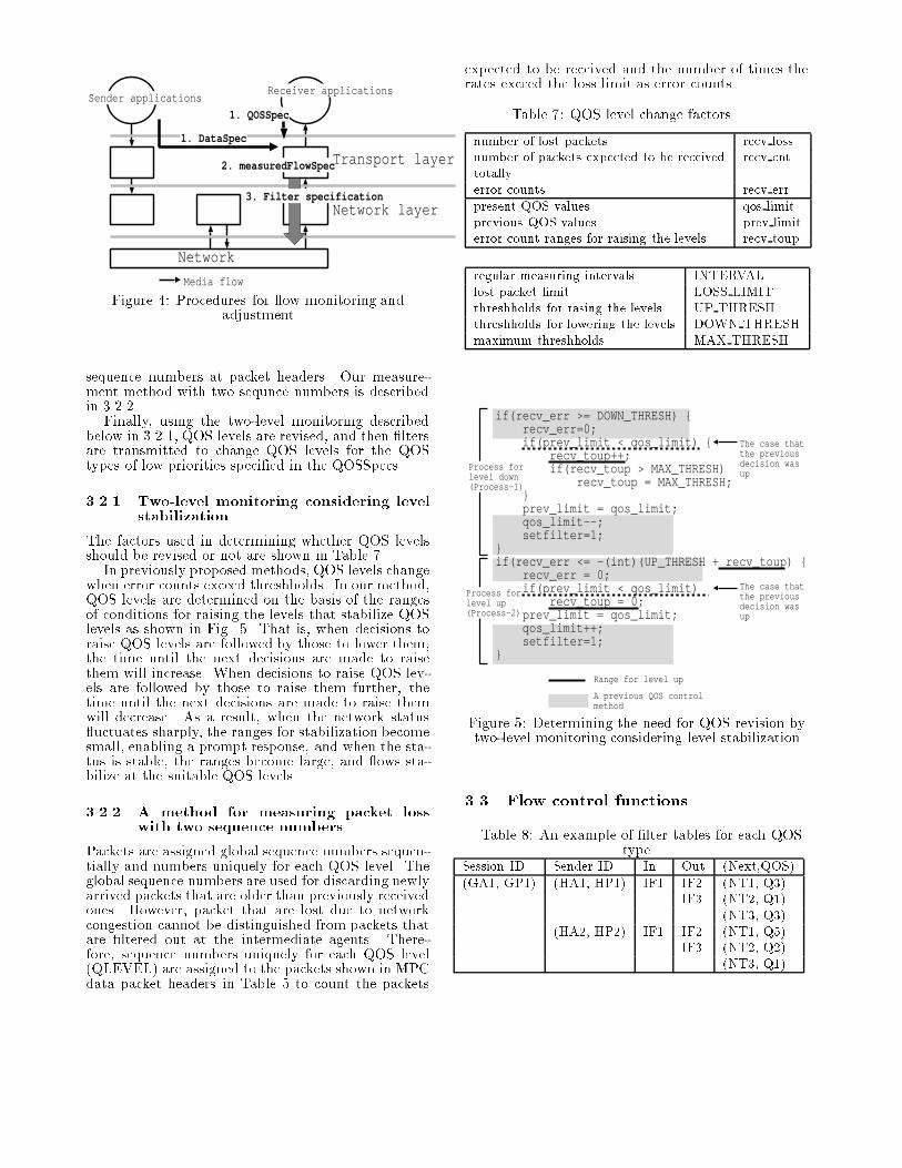
3. Filter specificationFigure 4: Procedures for ow monitoring andadjustmentsequence numbers at packet headers. Our measure-ment method with two sequnce numbers is describedin 3.2.2.Finally, using the two-level monitoring describedbelow in 3.2.1, QOS levels are revised, and then �ltersare transmitted to change QOS levels for the QOStypes of low priorities speci�ed in the QOSSpecs.3.2.1 Two-level monitoring considering levelstabilizationThe factors used in determining whether QOS levelsshould be revised or not are shown in Table 7.In previously proposed methods, QOS levels changewhen error counts exceed threshholds. In our method,QOS levels are determined on the basis of the rangesof conditions for raising the levels that stabilize QOSlevels as shown in Fig. 5. That is, when decisions toraise QOS levels are followed by those to lower them,the time until the next decisions are made to raisethem will increase. When decisions to raise QOS lev-els are followed by those to raise them further, thetime until the next decisions are made to raise themwill decrease. As a result, when the network status uctuates sharply, the ranges for stabilization becomesmall, enabling a prompt response, and when the sta-tus is stable, the ranges become large, and ows sta-bilize at the suitable QOS levels.3.2.2 A method for measuring packet losswith two sequence numbersPackets are assigned global sequence numbers sequen-tially and numbers uniquely for each QOS level. Theglobal sequence numbers are used for discarding newlyarrived packets that are older than previously receivedones. However, packet that are lost due to networkcongestion cannot be distinguished from packets thatare �ltered out at the intermediate agents. There-fore, sequence numbers uniquely for each QOS level(QLEVEL) are assigned to the packets shown in MPCdata packet headers in Table 5 to count the packets
expected to be received and the number of times therates exceed the loss limit as error counts.Table 7: QOS level change factorsnumber of lost packets recv lossnumber of packets expected to be receivedtotally recv cnterror counts recv errpresent QOS values qos limitprevious QOS values prev limiterror count ranges for raising the levels recv toupregular measuring intervals INTERVALlost packet limit LOSS LIMITthreshholds for rasing the levels UP THRESHthreshholds for lowering the levels DOWN THRESHmaximum threshholds MAX THRESHif(recv_err >= DOWN_THRESH) { recv_err=0; if(prev_limit < qos_limit) { recv_toup++; if(recv_toup > MAX_THRESH) recv_toup = MAX_THRESH; } prev_limit = qos_limit; qos_limit--; setfilter=1;}if(recv_err <= -(int)(UP_THRESH + recv_toup) { recv_err = 0; if(prev_limit < qos_limit) recv_toup = 0; prev_limit = qos_limit; qos_limit++; setfilter=1;}
Process forlevel down(Process-1)
Process forlevel up(Process-2)
The case that the previousdecision was up
Range for level up
A previous QOS control method
The case that the previousdecision was upFigure 5: Determining the need for QOS revision bytwo-level monitoring considering level stabilization3.3 Flow control functionsTable 8: An example of �lter tables for each QOStypeSession ID Sender ID In Out (Next,QOS)(GA1, GP1) (HA1, HP1) IF1 IF2 (NT1, Q3)IF3 (NT2, Q1)(NT3, Q3)(HA2, HP2) IF1 IF2 (NT1, Q5)IF3 (NT2, Q2)(NT3, Q1)
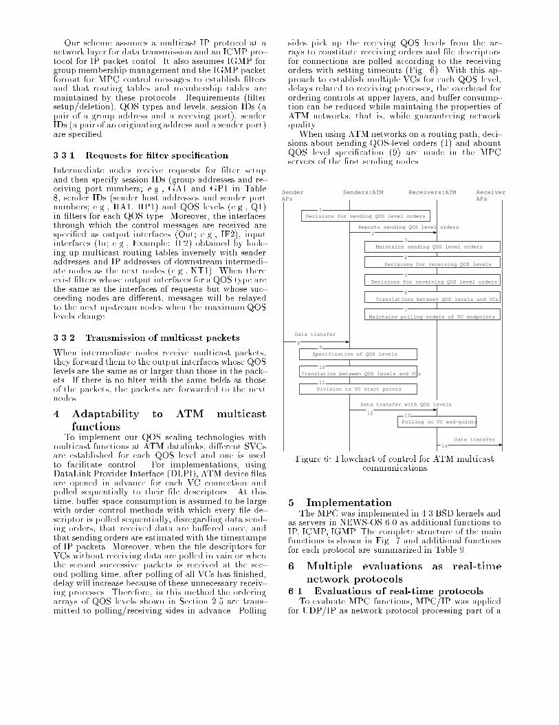
Our scheme assumes a multicast IP protocol at anetwork layer for data transmission and an ICMP pro-tocol for IP packet contol. It also assumes IGMP forgroup membership management and the IGMP packetformat for MPC control messages to establish �ltersand that routing tables and membership tables aremaintained by these protocols. Requirements (�ltersetup/deletion), QOS types and levels, session IDs (apair of a group address and a receving port), senderIDs (a pair of an originating address and a sender port)are speci�ed.3.3.1 Requests for �lter speci�cationIntermediate nodes receive requests for �lter setupand then specify session IDs (group addresses and re-ceiving port numbers; e.g., GA1 and GP1 in Table8, sender IDs (sender host addresses and sender portnumbers; e.g., HA1, HP1) and QOS levels (e.g., Q1)in �lters for each QOS type. Moreover, the interfacesthrough which the control messages are received arespeci�ed as output interfaces (Out; e.g., IF2), inputinterfaces (In; e.g., Example: IF2) obtained by look-ing up multicast routing tables inversely with senderaddresses and IP addresses of downstream intermedi-ate nodes as the next nodes (e.g., NT1). When thereexist �lters whose output interfaces for a QOS type arethe same as the interfaces of requests but whose suc-ceeding nodes are di�erent, messages will be relayedto the next upstream nodes when the maximumQOSlevels change.3.3.2 Transmission of multicast packetsWhen intermediate nodes receive multicast packets,they forward them to the output interfaces whose QOSlevels are the same as or larger than those in the pack-ets. If there is no �lter with the same �elds as thoseof the packets, the packets are forwarded to the nextnodes.4 Adaptability to ATM multicastfunctionsTo implement our QOS scaling technologies withmulticast functions at ATM datalinks, di�erent SVCsare established for each QOS level and one is usedto facilitate control. For implementations, usingDataLink Provider Interface (DLPI), ATM device �lesare opened in advance for each VC connection andpolled sequentially to their �le descriptors. At thistime, bu�er space consumption is assumed to be largewith order control methods with which every �le de-scriptor is polled sequentially, disregarding data send-ing orders, that received data are bu�ered once, andthat sending orders are estimated with the timestampsof IP packets. Moreover, when the �le descriptors forVCs without receiving data are polled in vain or whenthe second successive packets is received at the sec-ond polling time, after polling of all VCs has �nished,delay will increase because of these unnecessary receiv-ing processes. Therefore, in this method the orderingarrays of QOS levels shown in Section 2.5 are trans-mitted to polling/receiving sides in advance. Polling
sides pick up the receving QOS levels from the ar-rays to constitute receiving orders and �le descriptorsfor connections are polled according to the receivingorders with setting timeouts (Fig. 6). With this ap-proach to establish multiple VCs for each QOS level,delays related to receiving processes, the overhead forordering controls at upper layers, and bu�er consump-tion can be reduced while maintaing the properties ofATM networks, that is, while guaranteeing networkquality.When using ATM networks on a routing path, deci-sions about sending QOS-level orders (1) and abountQOS level speci�cation (9) are made in the MPCservers of the �rst sending nodes.Senders:ATM Receivers:ATMSender
APsReceiver APs
Data transfer
Reports sending QOS level orders
Data transfer
Decisions for sending QOS level orders
Maintains sending QOS level orders
Decisions for receiving QOS levels
Decisions for receiving QOS level orders
Translations between QOS levels and VCs
Specification of QOS levels
Translation between QOS levels and VCs
Maintains polling orders of VC endpoints
Polling on VC end-points
1
23
4
5
6
7
89
10
11
12 13
14
Division to VC start points
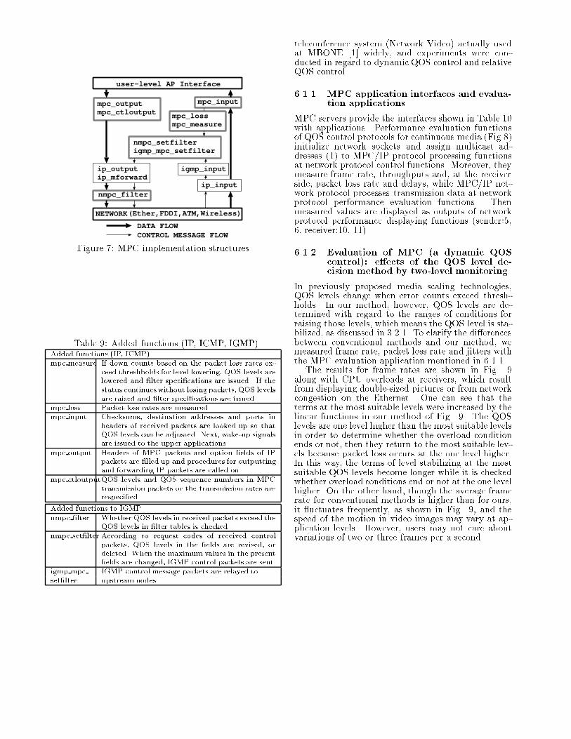
Data transfer with QOS levelsFigure 6: Flowchart of control for ATM multicastcommunications5 ImplementationThe MPC was implemented in 4.3 BSD kernels andas servers in NEWS-OS 6.0 as additional functions toIP, ICMP, IGMP. The complete structure of the mainfunctions is shown in Fig. 7 and additional functionsfor each protocol are summarized in Table 9.6 Multiple evaluations as real-timenetwork protocols6.1 Evaluations of real-time protocolsTo evaluate MPC functions, MPC/IP was appliedfor UDP/IP as network protocol processing part of a
user-level AP Interface
mpc_outputmpc_ctloutput
ip_outputip_mforward
mpc_input
igmp_input
ip_input
mpc_lossmpc_measure
nmpc_setfilterigmp_mpc_setfilter
CONTROL MESSAGE FLOWDATA FLOW
nmpc_filter
NETWORK(Ether,FDDI,ATM,Wireless)Figure 7: MPC implementation structuresTable 9: Added functions (IP, ICMP, IGMP)Added functions (IP, ICMP)mpc measure If down counts based on the packet loss rates ex-ceed threshholds for level lowering, QOS levels arelowered and �lter speci�cations are issued. If thestatus continueswithout losing packets, QOS levelsare raised and �lter speci�cations are issued.mpc loss Packet loss rates are measured.mpc input Checksums, destination addresses and ports inheaders of received packets are looked up so thatQOS levels can be adjusted. Next, wake-up signalsare issued to the upper applications.mpc output Headers of MPC packets and option �elds of IPpackets are �lled up and procedures for outputtingand forwarding IP packets are called on.mpc ctloutputQOS levels and QOS sequence numbers in MPCtransmission packets or the transmission rates arerespeci�ed.Added functions to IGMPnmpc �lter Whether QOS levels in received packets exceed theQOS levels in �lter tables is checked.nmpc set�lter According to request codes of received controlpackets, QOS levels in the �elds are revised, ordeleted. When the maximum values in the present�elds are changed, IGMP control packets are sent.igmp mpc IGMP control message packets are relayed toset�lter upstream nodes.
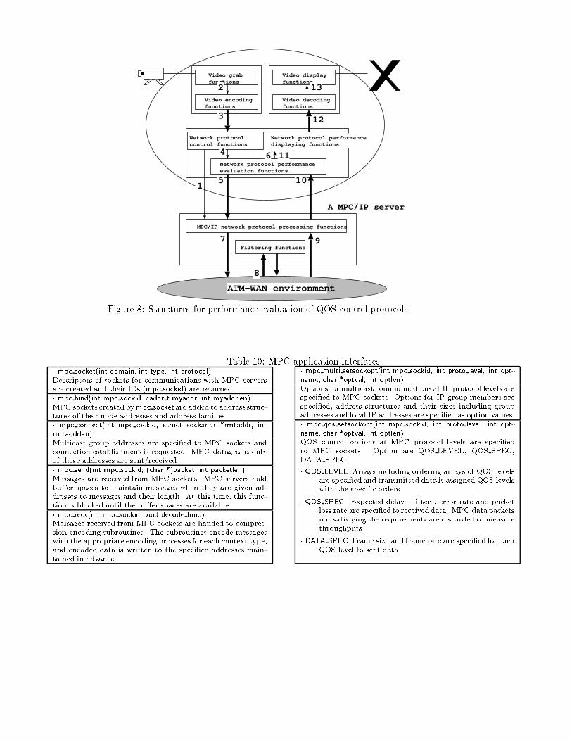
teleconference system (Network Video) actually usedat MBONE [1] widely, and experiments were con-ducted in regard to dynamic QOS control and relativeQOS control.6.1.1 MPC application interfaces and evalua-tion applicationsMPC servers provide the interfaces shown in Table 10with applications. Performance evaluation functionsof QOS control protocols for continuous media (Fig.8)initialize network sockets and assign multicast ad-dresses (1) to MPC/IP protocol processing functionsat network protocol control functions. Moreover, theymeasure frame rate, throughputs and, at the receiverside, packet loss rate and delays, while MPC/IP net-work protocol processes transmission data at networkprotocol performance evaluation functions. Thenmeasured values are displayed as outputs of networkprotocol performance displaying functions (sender:5,6, receiver:10, 11).6.1.2 Evaluation of MPC (a dynamic QOScontrol): e�ects of the QOS level de-cision method by two-level monitoringIn previously proposed media scaling technologies,QOS levels change when error counts exceed thresh-holds. In our method, however, QOS levels are de-termined with regard to the ranges of conditions forraising those levels, which means the QOS level is sta-bilized, as discussed in 3.2.1. To clarify the di�erencesbetween conventional methods and our method, wemeasured frame rate, packet loss rate and jitters withthe MPC evaluation application mentioned in 6.1.1.The results for frame rates are shown in Fig. 9along with CPU overloads at receivers, which resultfrom displaying double-sized pictures or from networkcongestion on the Ethernet. One can see that theterms at the most suitable levels were increased by thelinear functions in our method of Fig. 9. The QOSlevels are one level higher than the most suitable levelsin order to determine whether the overload conditionends or not, then they return to the most suitable lev-els because packet loss occurs at the one level higher.In this way, the terms of level stabilizing at the mostsuitable QOS levels become longer while it is checkedwhether overload conditions end or not at the one levelhigher. On the other hand, though the average framerate for conventional methods is higher than for ours,it uctuates frequently, as shown in Fig. 9, and thespeed of the motion in video images may vary at ap-plication levels. However, users may not care aboutvariations of two or three frames per a second.
Video grab functions
Video encoding functions
A MPC/IP server
MPC/IP network protocol processing functions
Filtering functions
Network protocol control functions
Network protocol performance evaluation functions
Video display functions
Video decoding functions
ATM-WAN environment
1
2
3
4
5
6
7
8
9
10
11
12
13
Network protocol performance displaying functions
Figure 8: Structures for performance evaluation of QOS control protocolsTable 10: MPC application interfaces� mpc socket(int domain, int type, int protocol)Descriptors of sockets for communications with MPC serversare created and their IDs (mpc sockid) are returned.� mpc bind(int mpc sockid, caddr t myaddr, int myaddrlen)MPC sockets created bympc socket are added to address struc-tures of their node addresses and address families.� mpc connect(int mpc sockid, struct sockaddr *rmtaddr, intrmtaddrlen)Multicast group addresses are speci�ed to MPC sockets andconnection establishment is requested. MPC datagrams onlyof these addresses are sent/received.� mpc send(int mpc sockid, (char *)packet, int packetlen)Messages are received from MPC sockets. MPC servers holdbu�er spaces to maintain messages when they are given ad-dresses to messages and their length. At this time, this func-tion is blocked until the bu�er spaces are available.� mpc recv(int mpc sockid, void decode func)Messages received from MPC sockets are handed to compres-sion encoding subroutines. The subroutines encode messageswith the appropriate encoding processes for each context type,and encoded data is written to the speci�ed addresses main-tained in advance.� mpc multi setsockopt(int mpc sockid, int proto level, int opt-name, char *optval, int optlen)Options for multicast communications at IP protocol levels arespeci�ed to MPC sockets. Options for IP group members arespeci�ed, address structures and their sizes including groupaddresses and local IP addresses are speci�ed as option values.� mpc qos setsockopt(int mpc sockid, int proto level, int opt-name, char *optval, int optlen)QOS control options at MPC protocol levels are speci�edto MPC sockets. Option are QOS LEVEL, QOS SPEC,DATA SPEC.� QOS LEVEL Arrays including ordering arrays of QOS levelsare speci�ed and transmitted data is assigned QOS levelswith the speci�c orders.� QOS SPEC Expected delays, jitters, error rate and packetloss rate are speci�ed to received data. MPC data packetsnot satisfying the requirements are discarded to measurethroughputs.� DATA SPEC Frame size and frame rate are speci�ed for eachQOS level to sent data.

0
5
10
15
20
25
30
35
40[fps]
0 100 200 300 400 500 600 700 800 900[sec]
"Our Method""Conventional Method"Figure 9: Evaluation of frame rate
0
5
10
15
20
25
30[%]
0 100 200 300 400 500 600 700 800 900[sec]
"Our Method""Conventional Method"Figure 10: Evaluation of error rate
-50
0
50
100
150
200
250
300
350
400[msec]
0 100 200 300 400 500 600 700 800 900[sec]
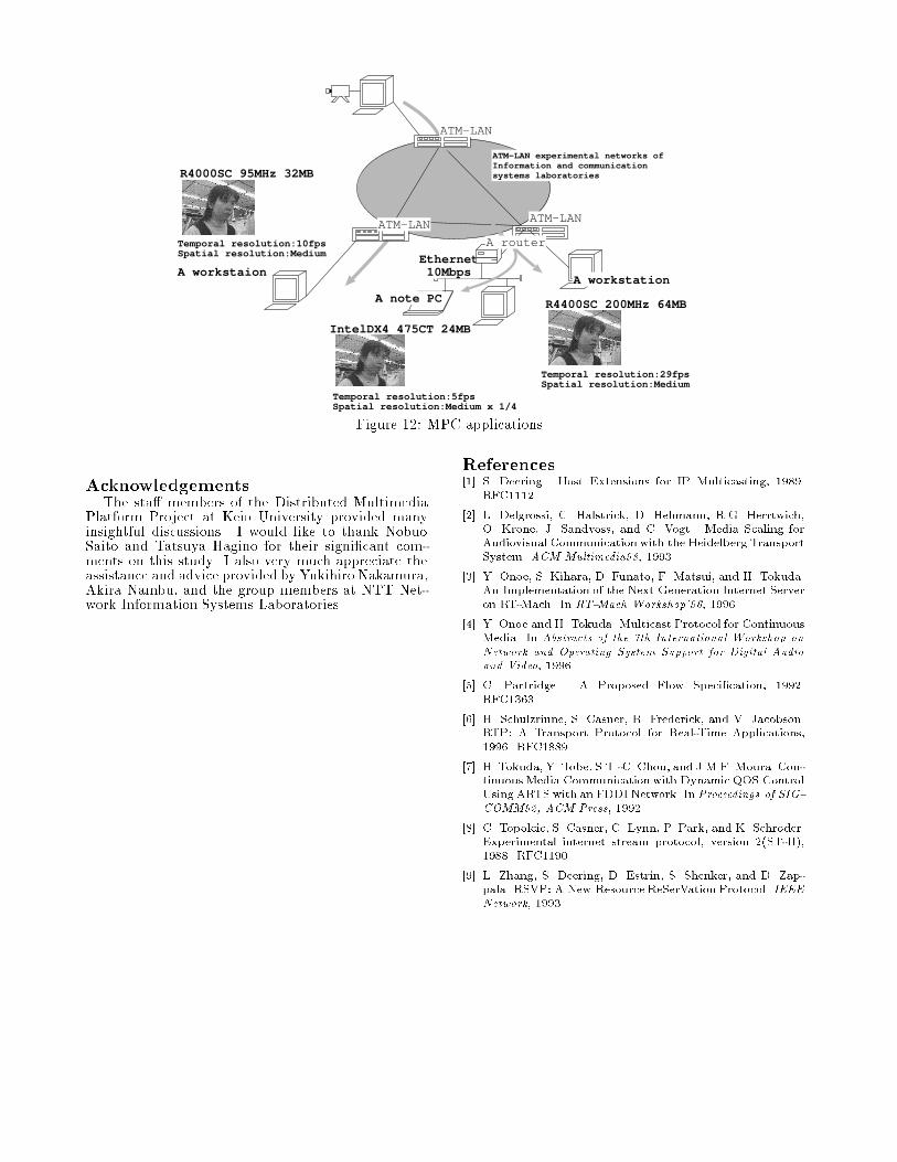
"Our Method""Conventional Method"Figure 11: Evaluation of delay jittersThe evaluation results for packet loss rate are shownin Fig. 10; the averages were 10.19% for conventionaltechnology and 2.94% for our method. Therefore, con-ventional approaches may result in video images hav-ing many blank blocks, and the displayed video im-ages could be disordered more frequently. Moreover,from the evaluation result for jitters in Fig. 11, theaverages were 84.73 msec for the conventional methodand 28.66 msec for our method with video images thatdo not move smoothly. From the above comparisons,we can conclude that dynamic QOS control with thetwo-level monitoring is preferable to conventional onein terms of the stabilization of average packet-loss rateand jitters.6.1.3 Evaluation with multimedia application(relative QOS control)Our experimental environment for examining thee�ect of relative QOS control is shown in Fig. 12 andthe results are summarized in Table 11. When a re-ceiver workstation was the gateway between an ATMnetwork and an Ethernet, and multicast packets wereforwarded from B to a notebook PC, the implementa-tion of this protocol functioned properly. As shown inthe experimental results for relative QOS evaluation(Table 11 and Fig. 12), though receiving capacities
Table 11: Mesurement resultsQOSData size Time Space MbpsA Normal 29 fps Medium 37 MDouble 14 fps Medium 18 MB Normal 10 fps Medium 13 MDouble 5 fps Medium 7 MC Half 10 fps Small 3.4 MNormal 5 fps Small 1.7 MDouble 3 fps Small 1.2 Mvary for each receiver node, all nodes can receive thesame movie images with various levels of quality vary-ing according to their receiving capacity.7 ConsiderationsIn the future, as we move to IPv6, the next-generation IP, how to map ows to the QOS connec-tions established for each ow ID of the IP switch andcell switch routers will be an important issue. Else-where at this time experiments are being conductedover high-speed ATM networks, and MPC will be ap-plied to integrated network environments with mobileLAN.8 Future studiesKeio University, NTT Information and Communi-cation Systems Laboratories and NTT Optical Net-work Systems Laboratories have started ultra high-speed computer network projects to carry out jointutilization tests of multimedia communications. Inthe experimental networks, �ve Keio University cam-puses at Shinanomachi, Mita, Yagami, Hiyoshi, andFujisawa and NTT Yokosuka research laboratoriesare connected by 155.5Mbps (135Mbps practically)high�speed links and ATM switches. Evaluation ex-periments for the MPC functions are now underwayfor continuous media processing and high-speed com-munications.
ATM-LAN experimental networks ofInformation and communication systems laboratories
ATM-LAN
Ethernet 10Mbps
A note PC
A workstation
A router
R4400SC 200MHz 64MB
R4000SC 95MHz 32MB
IntelDX4 475CT 24MB
Temporal resolution:29fpsSpatial resolution:Medium
Temporal resolution:10fpsSpatial resolution:Medium
Temporal resolution:5fpsSpatial resolution:Medium x 1/4
A workstaion
ATM-LAN
ATM-LAN
Figure 12: MPC applicationsAcknowledgementsThe sta� members of the Distributed MultimediaPlatform Project at Keio University provided manyinsightful discussions. I would like to thank NobuoSaito and Tatsuya Hagino for their signi�cant com-ments on this study. I also very much appreciate theassistance and advice provided by Yukihiro Nakamura,Akira Nambu, and the group members at NTT Net-work Information Systems Laboratories. References[1] S. Deering. Host Extensions for IP Multicasting, 1989.RFC1112.[2] L. Delgrossi, C. Halstrick, D. Hehmann, R.G. Herrtwich,O. Krone, J. Sandvoss, and C. Vogt. Media Scaling forAudiovisual Communication with the Heidelberg TransportSystem. ACM Multimedia93, 1993.[3] Y. Onoe, S. Kihara, D. Funato, F. Matsui, and H. Tokuda.An Implementation of the Next Generation Internet Serveron RT-Mach. In RT-Mach Workshop'96, 1996.[4] Y. Onoe and H. Tokuda. Multicast Protocol for ContinuousMedia. In Abstracts of the 7th International Workshop onNetwork and Operating System Support for Digital Audioand Video, 1996.[5] C. Partridge. A Proposed Flow Speci�cation, 1992.RFC1363.[6] H. Schulzrinne, S. Casner, R. Frederick, and V. Jacobson.RTP: A Transport Protocol for Real-Time Applications,1996. RFC1889.[7] H. Tokuda, Y. Tobe, S.T.-C. Chou, and J.M.F. Moura. Con-tinuous Media Communication with Dynamic QOS ControlUsing ARTS with an FDDI Network. In Proceedings of SIG-COMM92, ACM Press, 1992.[8] C. Topolcic, S. Casner, C. Lynn, P. Park, and K. Schroder.Experimental internet stream protocol, version 2(ST-II),1988. RFC1190.[9] L. Zhang, S. Deering, D. Estrin, S. Shenker, and D. Zap-pala. RSVP: A New Resource ReSerVation Protocol. IEEENetwork, 1993.
Related Documents