Professional Audio Equipment OWNER’S MANUAL Lexicon QLI-32 Immersive Processor ®

QLI32 Manual RevH Original (1)
Dec 11, 2015
processador para cinema
Welcome message from author
This document is posted to help you gain knowledge. Please leave a comment to let me know what you think about it! Share it to your friends and learn new things together.
Transcript

Professional Audio Equipment
O W N E R ’ S M A N U A L
Lexicon QLI-32Immersive Processor
®

IMPORTANT SAFETY INSTRUCTIONS
SAFETY INSTRUCTIONS
NOTICE FOR CUSTOMERS IF YOUR UNIT IS EQUIPPED WITH A POWER CORD.
WARNING: THIS APPLIANCE SHALL BE CONNECTED TO A MAINS SOCKET OUTLET WITH A PROTECTIVE EARTHING CONNECTION.
The cores in the mains lead are coloured in accordance with the following code:
GREEN and YELLOW - Earth BLUE - Neutral BROWN - Live
As colours of the cores in the mains lead of this appliance may not cor-respond with the coloured markings identifying the terminals in your plug, proceed as follows:
• The core which is coloured green and yellow must be connected to the terminal in the plug marked with the letter E, or with the earth symbol, or coloured green, or green and yellow.
• The core which is coloured blue must be connected to the terminal marked N or coloured black.
• The core which is coloured brown must be connected to the terminal marked L or coloured red.
This equipment may require the use of a different line cord, attachment plug, or both, depending on the available power source at installation. If the attachment plug needs to be changed, refer servicing to qualified service personnel who should refer to the table below. The green/yellow wire shall be connected directly to the units chassis.
CONDUCTORWIRE COLOR
Normal AltL LIVE BROWN BLACK
N NEUTRAL BLUE WHITE
E EARTH GND GREEN/YEL GREEN
WARNING: If the ground is defeated, certain fault conditions in the unit or in the system to which it is connected can result in full line voltage between chassis and earth ground. Severe injury or death can then result if the chassis and earth ground are touched simultaneously.
WARNING FOR YOUR PROTECTIONPLEASE READ THE FOLLOWING:
KEEP THESE INSTRUCTIONS
HEED ALL WARNINGS
FOLLOW ALL INSTRUCTIONS
THE APPARATUS SHALL NOT BE EXPOSED TO DRIPPING OR SPLASHING LIQUID AND NO OBJECT FILLED WITHI LIQUID, SUCH AS VASES, SHALL BE PLACED ON THE APPARATUS.
CLEAN ONLY WITH A DRY CLOTH.
DO NOT BLOCK ANY OF THE VENTILATION OPENINGS. INSTALL IN ACCORDANCE WITH THE MANUFACTURER’S INSTRUCTIONS.
DO NOT INSTALL NEAR ANY HEAT SOURCES SUCH AS RADIATORS, HEAT REGISTERS, STOVES, OR OTHER APPARATUS THAT PRODUCE HEAT.
ONLY USE ATTACHMENTS/ACCESSORIES SPECIFIED BY THE MANUFACTURER.
UNPLUG THIS APPARATUS DURING LIGHTNING STORMS OR WHEN UNUSED FOR LONG PERIODS OF TIME.
Do not defeat the safety purpose of the polarized or grounding-type plug. A polarized plug has two blades with one wider than the other. A grounding type plug has two blades and a third grounding prong. The wide blade or third prong are provided for your safety. If the provided plug does not fit your outlet, consult an electrician for replacement of the obsolete outlet.
Protect the power cord from being walked on or pinched particularly at plugs, convenience receptacles, and the point where they exit from the apparatus.
Use only with the cart stand, tripod bracket, or table specified by the manufacture, or sold with the apparatus. When a cart is used, use caution when moving the cart/apparatus combination to avoid injury from tip-over.
Refer all servicing to to qualified service personnel. Servicing is required when the apparatus has been damaged in any way, such as power-supply cord or plug is damaged, liquid has been spilled or objects have fallen into the apparatus, the apparatus has been exposed to rain or moisture, does not operate normally, or has been dropped.
MAINS DISCONNECT: The plug shall remain readily operable. For rack-mount or installation where plug is not accessible, an all-pole mains switch with a contact separation of at least 3 mm in each pole shall be incorporated into the electrical installation of the rack or building.
FOR UNITS EQUIPPED WITH EXTERNALLY ACCESSIBLE FUSE RECEPTACLE: Replace fuse with same type and rating only. 1Amp slow-blow fuse.
MULTIPLE-INPUT VOLTAGE: This equipment may require the use of a different line cord, attachment plug, or both, depending on the available power source at installation. Connect this equipment only to the power source indicated on the equipment rear panel. To reduce the risk of fire or electric shock, refer servicing to qualified service personnel or equivalent.
If connected to 240V supply, a suitable CSA/UL certified power cord shall be used for this supply.
This Equipment is intended for rack mount use only.
ELECTROMAGNETIC COMPATIBILITY
This device complies with part 15 of the FCC Rules and the Product Specifications noted on the Declaration of Conformity. Operation is subject to the following two conditions:
• this device may not cause harmful interference, and
• this device must accept any interference received, including interference that may cause undesired operation.
Operation of this unit within significant electromagnetic fields should be avoided.
IMPORTANT SAFETY INSTRUCTIONS
DECLARATION OF CONFORMITYManufacturer’s Name: Lexicon ProManufacturer’s Address: 10653 South River Front Parkway, Suite 300 South Jordan, UT 84095, USAdeclares that the product:
Product name: Lexicon QLI-32 Immersive ProcessorNote: Product name may be suffixed by the EU.
Product option: None
conforms to the following Product Specifications:
Safety: IEC 60065 -- 2001:7th ED + AM 1-- 05 UL 60065 -- 2007 CAN/CSA 60065 -- 2003 + AM 1-- 05 EMC: EN 55103:2009 EN 61000--3:2010 EN 55022:2010 EN 61000-4:2010
Supplementary Information:
The product herewith complies with the requirements of the:Low Voltage Directive 2006/95/ECEMC Directive 2004/108/EC.RoHS Directive 2002/95/ECWEEE Directive 2002/96/EC
With regard to Directive 2005/32/EC and EC Regulation 1275/2008 of 17 December 2008, this product is designed, produced, and classified as Professional Audio Equipment and thus is exempt from this Directive.
Jim Pennock Director of Technology 10653 South River Front Parkway, Suite 300 South Jordan, UT 84095, USA Date: April 21, 2015
European Contact: Your local Lexicon Sales and Service Office or
Harman Music Group10653 South River Front Parkway, Suite 300 South Jordan, UT 84095, USA
If you want to dispose this product, do not mix it with general household waste. There is a separate collection system for used electronic products in accordance with legislation that requires proper treatment, recovery and recycling.
Private household in the 25 member states of the EU, in Switzerland and Norway may return their used electronic products free of charge to designated collection facilities or to a retailer (if you purchase a similar new one).
For Countries not mentioned above, please contact your local authorities for a correct method of disposal.
By doing so you will ensure that your disposed product undergoes the necessary treatment, recovery and recycling and thus prevent potential negative effects on the environment and human health.
U.K. MAINS PLUG WARNING
A molded mains plug that has been cut off from the cord us unsafe. Discard the mains plug at a suitable disposal facility. NEVER UNDER ANY CIRCUMSTANCES SHOULD YOU INSERT A DAMAGED OR CUT MAINS PLUG INTO A 13 AMP POWER SOCKET. Do not use the mains plug without the cover in place. Replacement fuse covers can be obtained from your local retailer. Replacement fuses are 13 amps and MUST be ASTA approved to BS1362.
WarrantyThis warranty is valid only for the original purchaser and only in the United States. If outside the United States please contact the local Lexicon® distribu-tor.
1. The warranty registration card that accompanies this product must be mailed within 30 days after purchase date to validate this warranty. Proof-of-purchase is considered to be the burden of the consumer.
2. Lexicon Professional warrants this product, when bought and used solely within the U.S., to be free from defects in materials and workmanship under normal use and service.
3. Lexicon Professional’s liability under this warranty is limited to repairing or, at our discretion, replacing defective materials that show evidence of defect, provided the product is returned to Lexicon Professional WITH RETURN AUTHORIZATION from the factory, where all parts and labor will be covered up to a period of 3 years. A Return Authorization number must be obtained from Lexicon Professional by telephone. The company shall not be liable for any consequential damage as a result of the product’s use.
4. Lexicon Professional reserves the right to make changes in design or make additions to or improvements upon this product without incurring any obligation to install the same additions or improvements on products pre-viously manufactured.
5. The foregoing is in lieu of all other warranties, expressed or implied, and Lexicon Professional neither assumes nor authorizes any person to assume on its behalf any obligation or liability in connection with the sale of this product. In no event shall Lexicon Professional or its dealers be liable for special or consequential damages or from any delay in the performance of this warranty due to causes beyond its control.

TABLE OF CONTENTS
INTRODUCTION ................................................................... 2
QLI-32 SPECIFICATIONS ....................................................... 3
THE FRONT PANEL .............................................................. 5
THE REAR PANEL ................................................................ 6
USING THE QLI-32 .............................................................. 7Installation .................................................................... 7Powering Up the QLI-32 .............................................. 7Network Configuration ................................................. 7Overview Page ............................................................... 8Control Menu ............................................................... 8Equalization .................................................................. 9Calibration Mic Setup ................................................... 10Auto Equalization Procedure ......................................... 10LFE Equalization Procedure .......................................... 11Copy an Equalization Curve ......................................... 12RTA Viewing Controls .................................................. 12Manually Adjust Outputs .............................................. 12Sending TCP Automation Commands .......................... 12BLU link I/O ................................................................ 12
SYSTEM CONFIGURATION ................................................... 13File Managment ............................................................ 13Room Configuration ..................................................... 13Room Setup Diagrams............................................. 14-21Channel Routing ........................................................... 22System Tab .................................................................... 22Firmware Updates ......................................................... 23Diagnostics .................................................................... 23Restore Factory Settings ................................................ 23
ANALOG DB25 CABLE DIAGRAMS ....................................... 24
DIGITAL RJ45 CABLE DIAGRAMS .......................................... 25
AUTOMATION BLOCK DIAGRAM .......................................... 26
TCP AUTOMATION COMMANDS ........................................... 27

2
INTRODUCTIONCongratulations and thank you for purchasing the QLI-32 Immersive Processor! Intelligent and flexible, this cinema processor is fully compatible with existing cinema processors and designed to deliver up to 32 channels of surround sound. For an immersive and life-like sound experience, the QLI-32 is the smart solution for any cinema.
INCLUDED ITEMS
• QLI-32 Immersive Processor• This owner's manual• Power Cord• Lexicon Warranty Card

3
QLI-32 SURROUND SPECIFICATIONS
ANALOG INPUTSConnector One 25-pin Dsub connector, FemaleLevel (for -20dBFS) +300mVFreq Response @48K 20Hz - 20kHz, ±.15dB A/D Conversion 24 bitsA/D Dyn Range 105dB A-weightedTHD <0.002% 20 → 20kHz @ -20dBFSCrosstalk @ 1Khz <–75dB at 20 → 20k with a -20dBFS input signal
MICROPHONE INPUTConnector XLR/TRS Combo Jack, FemaleImpedance 20K Ohm, balancedNominal Input Level +3mVFreq Response 20Hz - 20kHz, ±.3dBTHD <.008% 20Hz → 20kHz @ 3µVA/D Dyn Range >112 dB unweighted, 115dB A-weighted
AES DIGITAL AUDIO INPUTConnectors 2 Stacked RJ45 ConnectorsFormat AES/EBUSample Rate 48, 96 kHzBit Depth 24-bitChannel Count 8 Channels
BLU LINK AUDIO INPUT/OUTPUTConnectors 2 Stacked RJ45 ConnectorsFormat Harman® BLU linkSample Rate 48kHzBit Depth 24 bitChannel Count In: 8 Channels Out: 32 ChannelsMaximum Cable Length 100 meters (328 feet)Latency 54ms
AUTOMATION INTERFACESConnector 12 Pin GPI Block Connector
INTERNAL STORAGEInternal non-volatile Flash.
POWER Requirements 100-240 VAC (±10%) 50-60Hz, 36W maxConnector 3-pin IEC
DIMENSIONSRack Units 1RUSize 19.0” W x 1.75” H x 9.5” D (483mm x 445mm x 241mm)Weight 7.70 lbs

4
REGULATORY APPROVALS
EMC:EN 55103-1:2009EN 61000-3-2:2010EN 61000-3-3:2008EN 55022:2010EN 55103-2:2009EN 61000-4-2:2008 Ed 2.0EN 61000-4-3:2010 Ed 3.2EN 61000-4-4:2007EN 61000-4-5:2006EN 61000-4-6:2006EN 61000-4-11:2004
SAFETY:IEC 60065 – 2001: 7th Ed + AM 1-05UL 60065 – 2007CAN/CSA 60065 – 2003 + AM 1-05
ENVIRONMENTOperating 0° to 40° CStorage 0° to 40 °C

5
THE FRONT PANEL
1. ON / OFF LED IndicatorIndicator is lights Green when device is powered on.
2. STATUS LED IndicatorLit Green when system is operating and Red when there is an error condi-tion. Flashing green means the system is not yet ready for operation (per-forming initialization).
3. QLI Immersive Processing Button Pressing the button toggles the QLI state between enabled (normal) and bypassed. Button backlight is Green when QLI processing is enabled. Not lit while in bypass mode.
4. MUTE Button Pressing the button toggles the device state between muted and unmuted. When the device is Muted the backlight will be red and all outputs will be muted.
5. Analog In IndicatorGreen LED lights when 8 channel analog input is selected.
6. AES / EBU Digital In IndicatorGreen LED lights when 16 channel AES/EBU input is selected.
7. BLU link In IndicatorGreen LED lights when input audio is taken from the BLU link loop.
8. Stereo Input ModeGreen LED lights when two channels of stereo input are being processed.
9. 5.1 Input ModeGreen LED lights when 6 channels (5 + LFE) of input are being processed.
10. 7.1 Input ModeGreen LED lights when 8 channels (7 + LFE) of input are being processed.
11. Signal In Indicator Green LED that lights if any enabled channel (stereo, 5.1, 7.1) of the select-ed source (analog, AES/EBU, BLU link) had a level exceeding -60 dBFS in the past 10 seconds.
12. BLU link Out IndicatorGreen LED that lights if any output had a level exceeding -60 dBFS in the past 10 seconds.
1 3 5 7 8 10 10
2 4 6 9 11

6
THE REAR PANEL
1. POWER JACKStandard 3-pin IEC power connector. 100-240 VAC (±10%), 50-60Hz automatic switching to correct voltage range.
2. BLU LINK IN/OUTRJ-45 connectors carrying 16 audio channels in and 32 channels out over BLU link digital audio interface.
3. AES/EBU INTwo RJ-45 connectors allow eight AES/EBU digital channels in each.
4. MICROPHONE INTRS/XLR combo jack for EQ microphone input. Mic level input signal expected. Balanced & Unbalanced 10V phantom power available.
5. POWER SWITCHFlip the rocker switch to turn QLI-32 ON or OFF.
6. ETHERNET INPUTRJ-45 connection used to network the QLI-32 device and control it via Ethernet.
7. AUTOMATION PINSTwelve pin block connector to send GPI automation controls to the device.
8. DB25 8-CHANNEL ANALOG INDB25 connector carries eight analog inputs.
NOTE:*Refer to the Appendix (Page 24) for connector pin out diagrams.
1 2 3 4
5 6 7 81 Amp

7
USING THE QLI
INSTALLATION1. Install the QLI-32 Immersive processor below any existing Cinema
Processor in the B-chain signal flow. 2. Disable any equalization, delays, matrixing, or crossovers prior to the
QLI-32 device. 3. Connect the power cable to any 50-60Hz 120-220V wall outlet. 4. Using an ethernet cable connect the device to the auditorium network
switch. 5. Connect the existing Cinema Processor audio output to one of the audio
inputs of the QLI-32 Immersive Processor (8 channel analog, BLU link, or digital AES/EBU).
6. Connect the QLI-32 BLU link output to the BLU link loop of Crown®
DCi Amplifiers or BLU link-to-Analog converter in your audio equip-ment rack.
POWERING UP THE QLI-321. Plug in the power cord.2. Flip the Power switch on the rear panel to the on position.3. Allow 30 seconds for the QLI-32 Immersive Processor to boot up.
NETWORK CONFIGURATION The QLI-32 processor can fit into a number of different network architec-tures. The most simple configuration available is with a direct ethernet con-nection to machine. Configuring the device to a theater control network will allow more devices to connect and automation commands to be sent.
To configure the QLI-32 Immersive Processor and apply custom network address settings access the web user interface.
NETWORK SETUP FOR FACTORY QLI-321. Directly connect a computer to the unit or connect unit to the same
router/switch as the computer. 2. Type 169.254.1.15 into the address bar of any web browser. If the QLI-
32 has factory settings this will be the correct IP Address to reach the web interface.
3. Navigate to the Configuration page by selecting the gear icon in the upper right corner of the page. username: admin password: admin
4. Navigate to the SyStem tab then the network SettingS sub menu. 5. Input the IPv4 IP Address, Subnet Mask, and Default Gateway that
match your current control network scheme.

8
CHANGE NON-FACTORY NETWORK SETTINGS1. Directly connect a computer to the unit or connect unit to the same
router/switch as the computer. 2. Type the current device IP Address into the address bar of any web
browser. 3. Navigate to the Configuration page by selecting the gear icon in the
upper right corner of the page. username: admin password: admin4. Navigate to the SyStem tab then the network SettingS sub menu. 5. Input the new IPv4 IP Address, Subnet Mask, and Default Gateway that
match your control network scheme.
LOCATE A QLI-32 ON NETWORKIf a units IP Address is forgotten or goes missing on the network use the fol-lowing procedure:
1. Install the USL Ethernet Discoverer software on a Windows PC. 2. Open the program and start a network device scan.3. Find the device that matches the serial number on the rear panel of the
QLI-32.4. Write down the matching IP Address or bookmark the web interface
page in your web browser.
RESET A QLI-32 IP ADDRESSIf unit cannot be found using the prior procedures the following steps will reset the QLI-32 to its factory settings.
1. Hold the Mute button on the front panel for seconds until the left-to-right light sequence completes.
2. Power reset the device.3. The IP Address of the device will now be 169.254.1.15.
NOTE:*Resetting the device IP settings will not reset all settings (EQ, Network, Room Dimensions, etc...) to factory default.
OVERVIEW PAGE The QLI-32 overview page shows real time status of the device through the front panel graphic. Additionally, it provides network information, site data, BLU link status, and firmware versions.
To visit the overview page enter the assigned IP Address of the QLI-32 into any web browser. Once on the initial overview page, you can navigate to other pages using the menu bar links or, with a narrow browser window, by selecting other pages in the drop down menu selector on the far right.
CONTROL MENU To manually control the QLI-32 Immersive processor use the Control page of the web interface. The Front Panel graphic and separate sections show the current status of the device. All changes to the control settings will be reflected on the front panel graphic above and on the actual front panel of the device. Only the SourCe and input mode settings are retained after sys-tem restarts.

9
SOURCEChoose the expected input type coming from the cinema processor to the QLI-32. This setting is preserved on system restart.
INPUT MODESelect the channel format of the source input. Changing the Input mode state will reset the QLI mode to Normal. This setting is preserved on system restart.
QLI STATUS Enable or Bypass Quantum Logic processing or Mute audio output. When enabled, Quantum Logic immersive processing will be handled by the device. When bypassed, surround inputs will be arrayed across surround speakers with an adjustable bypass surround delay. Channel equalization is applied in either case.
QLI MODE QLI has been designed to provide a highly immersive cinematic audio experience with all movie soundtracks. QLI is also equally effective for Alternative Content such as live broadcasts of music concerts (eg, opera), theater performances, and sporting events. In some instances, it may be preferable to set QLI to alternative Content mode in order to obtain an immersive experience more suitable to this type of content.
SURROUND INPUT LEVEL Content (movie soundtracks) produced for professional cinema applications expect the surround loudspeakers to be calibrated to a reference level of 82dB SPL, whereas content produced for consumer applications (DVD/Blu-ray) expect the surround loudspeakers to be calibrated to a reference level of 85dB SPL. The Surround input level control allows QLI to account for relative source level differences between Cinema and Consumer (DVD/Blu-ray) content if a consumer surround decoder is used. Set the Surround input level control to match the type of surround decoder in use.
Source Routing Surround Input LevelCinema Server Cinema Processor QLI-32 Cinema
DVD/Blu-ray (DD/DTS) Cinema Processor QLI-32 Cinema
DVD/Blu-ray Built-in Decoder QLI-32 Consumer
DVD/Blu-ray (DD/DTS) Consumer Decoder QLI-32 Consumer
EQUALIZATION The QLI-32 equalization tab allows the user to adjust the equalization curves of each channel to improve frequency response in auditoriums. The Real Time Analyzer (RTA) graphic provides 1/3 octave resolution in the fre-quency spectrum for each of the 32 channels of output.
The device factory settings have flat equalization curves and gains at zero on every channel. It is highly recommended to either manually EQ each chan-nel or run the Auto-EQ procedure to create the best listening experience.

10
SIGNAL GENERATORA signal generator exists on each channel with the following types of signals:
• Pink Noise - equal energy per octave noise• Sweep - 20Hz to 20kHz sweep with 4 second per octave rate• 100 Hz - sine wave with 100 Hertz frequency• 1 kHz - sine wave with 1000 Hertz frequency• 10 kHz - sine wave with 10,000 Hertz frequency
CALIBRATION MIC SETUP• Step 1Connect four omni-directional microphones to a microphone multiplexor device such as the USL MMP-10.
• Step 2Position the microphones at ear height (3.3-4 ft) in a diamond shaped pat-tern at several locations in the seating area (not closer than 5 ft to any wall or 16 ft from the screen).
• Step 3Connect the multiplexor output to the mic input of the QLI-32.
• Step 4Press the yellow SPL button to calibrate the microphone(s) driving the RTA while the pink noise generator of the processor is enabled.
• Step 5Adjust the Microphone Gain control until the indicated SPL matches the SPL on a reference meter.
NOTE:*Multiple microphone positions ensures spatial averaging and improves the overall quality of equalization by reducing the effect of specific room modes.
*All SPL readings are C-weighted decibels at a slow polling rate.
AUTO EQUALIZATION PROCEDUREWith the calibration microphones properly placed and the microphone mul-tiplexor connected to the QLI-32 you are now ready to run an Auto-EQ. • Step 1Select the Auto-EQ button on the equalization page.
• Step 2Using the drop down menus and check boxes select all the channels to EQ.
• Step 3Select any addition parameters (Gain Smoothing/Centering) to be processed during Auto-EQ.
• Step 4Select “Go!”. The processor will now go through the Auto-EQ process. Allow up to two minutes per channel to complete the process.

11
gain Smoothing - Applies smoothing to adjacent bands to create a more uniform EQ curve.
gain Centering - Applies a adjustment to the whole EQ curve to center on 0dB.
NOTE:*All Auto-EQ generated curves target the X-Curve and 85dBc SPL per SMPTE ST 202:2010 specification.
LFE PARAMETRIC EQThe LFE channel uses a parametric equalizer instead of a graphic equalizer. Note that selecting the LFE channel in the equalizer tab does NOT turn off pink noise on the previously selected channel. This allows pink noise to drive the LFE and center channels simultaneously so the transition frequency region can be viewed for possible phase errors. A suggested LFE adjustment procedure is below:
• Step 1On the Outputs Tab turn the generator on for both the Center channel and the LFE.
• Step 2Navigate to the Equalizer tab and select the LFE channel. The generator should already be on and pink noise should be visible on the RTA.
• Step 3At this point, confirm that pink noise is driving both the center and LFE channels.
• Step 4Adjust the leftmost (master) gain control until the LFE level matches the mid-band level of the center channel on the RTA display.
• Step 5Adjust the frequency control on the PEQ to the worst dip or peak in the LFE portion of the RTA display. You may use up to four PEQ’s depending on the amount of peaks and dips in the RTA.
• Step 7Set the Q and adjust the PEQ gain as required to remove the peak or dip. The Q can be increased to make the peak or notch narrower, or decreased to make it wider. The frequency can be adjusted as required to center the peak or notch on the notch or peak displayed on the RTA.
• Step 8If there is a notch in the transition region between the LFE and center chan-nel frequencies, try reversing the phase on the LFE channel (Invert button on the Outputs tab).
• Step 9Finally, adjust the leftmost gain control up to increase the LFE output as required. SMPTE RP 200-2002 calls for LFE to be 10dB above the center channel, but this may be excessive in some auditoriums.

12
COPY EQUALIZATION CURVESTo copy the EQ curve of one channel and apply it to another channel(s) select the “Copy” button below the RTA graphic on the equalization page. Note that this only copies the EQ curve of the source channel to the destina-tion channel. The Gain fader level is excluded in the copy.
RTA VIEWING CONTROLSTo adjust the viewing parameters of the RTA mouse over the graphical area. Here you can zoom in/out, increase the resolution of the Y-axis (dbC), change the decay, and offset the X-Curve. Smaller decay values will increase the polling rate while larger values give a more stable value over time. X-Curve control can be used to move the limit curves up or down to best fit the current RTA data.
MANUAL OUPUT ADJUSTMENTS Visit the outputS tab to manually mute, invert phase, or adjust chan-nel output faders. Channels are categorized into either Stage, Surrounds, Heights, and Back Surrounds. Grab a fader with a mouse-click and drag up or down to adjust the gain of that specific channel. Inverting a channel will invert the phase 180º, helpful if the wiring polarity is backwards on a speaker.
SENDING TCP AUTOMATION COMMANDSThe QLI-32 is capable of receiving TCP/IP commands from digital cinema servers or automation controllers if on the same network as the device send-ing commands.
Commands use the following ASCII form: “qli32.sys.command value”. TCP command strings must be sent to port 10001. To query the current state of an automation command ommit the value from the string.
For a full listing of all QLI-32 TCP command strings refer to page 27 - TCP Automation Commands.
BLU LINK I/OThe QLI-32 accepts up to 8 channels of BLU link inputs and outputs up to 32 channels. By default the QLI-32 will be mapped to the following BLU link channels: Input channel range: BLU link #65-81 Output channel range: BLU link #1-32
The routing of these channels are fully interchangable within their given BLU link range. To customize the starting channel of the input and output ranges or change the mapping within view the Channel Routing section on page 22.

13
SYSTEM CONFIGURATION
The Configuration menu can be accessed by selecting the gear icon in the top right corner of the user interface. The login credentials are admin:admin. In the Configuration menus the user is able to save/load configuration files, define room characterstics, alter channel routing, and edit system settings.
NOTE:*Saving configuration parameters may cause a short pause in audio playback. It is not recommended to edit system settings during a live show.
FILE MANAGEMENT The File tab allows a user to load or save a configuration to the device. A configuration file (.qli) is a snapshot of every setting on the device at that moment including:
• Room Dimensions• Seating Areas• Speaker Definitions & Locations • Equalization Curves• Bypass Surround Delays• Channel Routing • Network Settings
To load a previously saved configuration file select the folder icon.
To save a new configuration file select the disk icon.
ROOM CONFIGURATION In order to get a full immersive experience the user must provide the proces-sor with data regarding room dimensions, seating area, and speaker locations.Measurements can be input in units of feet or meters depending on what is chosen in SyStem -> general SettingS. After all Auditorium Size, Seating Area, and Speaker Location values have been entered and saved, values high-lighted in red should be examined for possible mistakes.
NOTE:*If the Measurment Unit setting is changed after room information has been entered, all values will automatically converted to the new units.

14
AUDITORIUM SIZEDefine the rectangular dimensions of the auditorium that the QLI-32 is installed for. • Width — distance of the left wall to right wall at the front and rear• Length — distance from the front to the rear of room• Height — distance from the floor to ceiling at the front and rear• Rear Elevation — height of floor at rear above the floor at the front• Reference Listening Position — X = distance from the theater center line, this should be 0.0 Y = distance from Y origin, normally 2/3rds of room length Z = height of reference listener’s ears above floor at front, normally 4ft (1.2m) + height of floor at reference position
Press the save button when each category is complete before moving to the next.
FRONT WIDTH
REAR WIDTH
LENGTH
-X +X
+Y
-Y
TOP VIEW
REFERENCE POSITION X = 0
REFERENCE POSITION YTOP VIEW
SIDE VIEW FRONT HEIGHT
LENGTH
+Y-Y
REAR
HEIGHT
REAR
ELEVATIONREFERENCE POSITION Z
REFERENCE POSITION Y
+Z
SIDE VIEW

15
SEATING AREASThe next step in calibrating the Quantum Logic engine is to define the seat-ing area(s) within the cinema auditorium. Normally, a room will be suffi-ciently defined within a single seating area.
If there is a gap creating distinct seating areas (i.e. a wide dividing aisle in stadium seating or a change in seating width due to a side entrance hallway) then you may define a second or third seating area in the menu. When more than one seating area is defined, they must be defined in order of front of theater to the rear (increasing Y values from Seating Area 1 to Seating Area 2).
Input the X, Y, and Z coordinates at the 6 vertices that outline the seat-ing area. The middle vertex will help capture the general shape of a curved row of seating. The origin point in the room is defined as the center of the screen at the floor. The coordinates are defined:
X = distance from center line origin (negative value to left, positive to right)Y = distance away from the screenZ = height of floor at that vertex above the floor at front
Press the save button when each category is complete before moving to the next.
SINGLE SEATING AREA EXAMPLE -X +X
4 16
40
60
128
2
+Y-Y
+Z
X Y Z
XX
X Y Z X Y Z
X Y Z X Y Z X Y Z
FRONT
REAR
-16
-16
12 12 12
58 5858 8 88 0
0 +16
+16
0 00
TOP VIEWSEATING AREA 1
DIMENSIONS
SIDE VIEW

16
-X +X
4 16
40
60
612
2
+Y-Y
+Z
X Y Z
XX
X Y Z X Y Z
X Y Z X Y Z X Y Z
FRONT
REAR
-15
-15
6 8 6
20 1818 0 00 0
0 +15
+15
0 00
X Y Z X Y Z X Y Z
X Y Z X Y Z X Y Z
FRONT
REAR
-16
-16
22 22 22
35 3535 7 77 0
0 +12
+12
3 33
XXX Y Z X Y Z X Y Z
X Y Z X Y Z X Y Z
FRONT
REAR
-16
-16
40 40 40
58 5858 12 1212 0
0 +16
+16
7 77
15
12
86
18
22
35
40
73
SEATING AREA 1
SEATING AREA 2
SEATING AREA 3
THREE SEATING AREAS EXAMPLEShown below is an example of an auditorium with three distict seating areas. Each defined seating area is able to accomodate curvatures, varied width, and sloped or stadium seating arrangements.
TOP VIEW
SIDE VIEW
DIMENSIONS

17
SPEAKER LOCATIONSThe last piece of information needed for the Quantum Logic immersive experience is the number and locations of the speakers in the auditorium. Like the seating area definitions, the origin point in the room is defined as the centerpoint of the screen at the floor.
On the dropdown of each speaker category choose the number of speakers or speaker pairs that exist. Next, enter the X, Y, and Z coordinates for each speaker defined.
Remember to press the save button before moving to the next category.
NOTE:*The maximum amount of speakers than can be defined must be less than or equal to 32.
Screens• Quantum Logic processing always requires these seven stage speakers.• Normally, with the Y origin being the front of screen, stage speakers will
have negative Y values.• If Stage Height speakers are in front of the screen then may have positive
Y values.• Three screen height channels are a requirement for a Quantum Logic
setup.• Any speaker behind the screen will need a negative Y value.
Surrounds• A minimum of two pairs (four speakers) are required.• A maximum of eight pairs (sixteen speakers) is allowed.• It is assumed that all surrounds are symmetrical so it is only necessary to
define one surround wall of speakers. • If the first speaker pair is on the wall between the screen and where the
seating area begins check the Gap box.• Speaker pairs must be defined from front to rear (increasing Y values).
Heights• It is assumed that all height surrounds are symmetrical so it is only neces-
sary to define one surround wall of speakers.• A minimum of two pairs (four speakers) are required.• A maximum of four pairs (eight speakers) are allowed.• Speaker pairs must be defined from front to rear (increasing Y values).
Rears• A minimum of two surround speakers are required.• A maximum of five speakers is allowed.• Speakers must be defined from rear corner to center of rear wall.

18
TOP VIEW
FRONT VIEW
+Y
-Y
Z
-X +X
Mains
Heights
Heights
Mains
STAGE SPEAKERS WITH CURVED SCREENShown below is an example of a symmetrical auditorium with a curved screen. In this configuration the Center and Center Height speakers with have X values of 0.0. Stage Left and Right (Mains or Heights) may have pos-itive Y values based on the arc angle of the screen and placement variations.
19
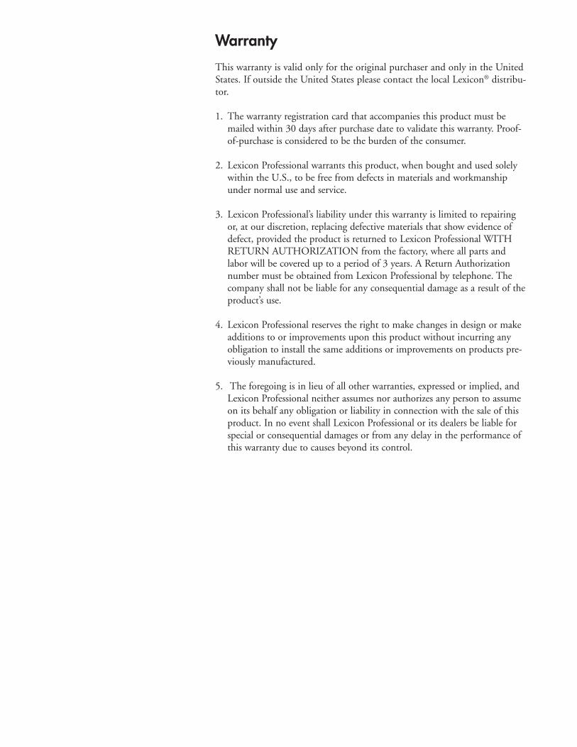
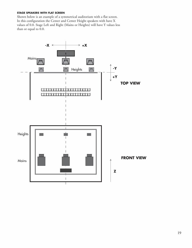
STAGE SPEAKERS WITH FLAT SCREENShown below is an example of a symmetrical auditorium with a flat screen. In this configuration the Center and Center Height speakers with have X values of 0.0. Stage Left and Right (Mains or Heights) will have Y values less than or equal to 0.0.
+Y
-Y
Z
-X +X
Mains
Heights
Heights
Mains
TOP VIEW
FRONT VIEW

20
TOP VIEW
Mains
Heights
Heights
Mains
+Y
-Y
Z
-X +X
STAGE SPEAKERS WITH OFFSET CURVED SCREENThe example below shows an auditorium with an offset screen to allow for an exit door on the right side of the room. In this configuration the Center and Center Height speakers with have negative X values. Stage Left and Right (Mains or Heights) may have positive Y values based on the arc angle of the screen and placement variations.
FRONT VIEW

21
SURROUND SPEAKERS LAYOUTThe figure below is an example of an auditorium using 7 surround pairs, 4 height pairs, and 3 rear speakers. Each speaker pair will have ascending Y values starting from the front of the auditorium to the rear.
In this example all Height Surround Z values will be equal since they are mounted at the same level in the auditorium. Lower surrounds 2-7 will have increasing Z values since they follow the slope of the seating.
+Y-Y
+Z
-X +X
Y: Surround 5
Z: Surround 5
Y: Right Surround 5
X: Right Surround 5
Rear Surrounds
+Y
-Y
Height Surrounds
Surrounds
Rear Surrounds
SIDE VIEW
TOP VIEW

22
CHANNEL ROUTING To alter the channel routing within the processor visit the routing tab within the System Configuration Menu. You are able to edit the following routing configurations:
• Analog Inputs• Digital AES Inputs• BLU link Inputs• BLU link Outputs
To make an edit to channel routing first choose the category of input/out-put. Next find the channel to re-route and use the drop down menu to make a change. You may mark a channel as unused if needed.
By default the QLI-32 will have standard SMPTE channel routing (L,C,R,LFE,Ls,Rs) for inputs. Ensure that the expected input channel rout-ing of the QLI-32 is consistent with the output from your cinema sound processor.
BLU LINK OFFSETSThe BLU link Input/Output ‘Starting Channel’ dropdown menus allow for editing the BLU link channels on which the device operates. For input, match whatever channels the upstream device is sending and make sure the input starting channel does not conflict.
For example, a default Dolby® CP-850 will output on BLU link channels 1-64. This would require the QLI-32 to have an input starting channel of 1 and an output starting channel of 65. The BLU link amplifiers would also need to match the output of the QLI-32.
SYSTEM TAB The SyStem tab in the System Configuration Menu allows the user to edit the following:
• General Settings - Change measurement unit and add bypass surround delay
• QLI Settings* - Edit the Room Factor Adjustment• Network Settings - Edit IPv4 networking addresses• NTP Settings - Point the device to a NTP server to syncronize the system
clock• Site Info - Edit the auditorium name, theater name, and audio processor
type
*NOTE:Based on Auditorium Size, Seating Area, and Speaker Location information, QLI automatically configures itself to provide optimal performance. How-ever, not all aspects of the room or playback system can be accounted for based on this information. The room faCtor adjuSt control is provided to allow minor adjustments to be made to the automated QLI configuration if required. For the vast majority of rooms there is no need to alter the room faCtor adjuSt, and this control can be left to its Auto setting. If needed, the room faCtor adjuSt should be used as part of the calibration and tuning of the audio playback system.

23
FIRMWARE UPDATES Visit the upgrade tab within the System Configuration Menu to push a system update to the QLI-32 immersive processor. Press the folder button to open a file prompt and select the .upd firmware file.
The latest QLI-32 firmware is available at the Lexicon Pro support page.
DIAGNOSTICS The diagnoStiCS tab shows detailed system information for troubleshooting and error checking.
BLU LINK STATUSThe BLU link status menu shows all detailed information regarding the BLU link chip in the processor. This information may be helpful if troubleshoot-ing BLU link related problems in a system.
• IN/OUT Cable Status — indicates the presence of a valid BLU link con-nection
• IN/OUT Corrected — shows the number of recoverable bit errors that have occurred
• IN/OUT Errors — shows the number of unrecoverable bit errors that have occurred
• Lock Source — mastership indicator• Sample Rate — current sample rate negotiated in the BLU link loop• BLU link Version — indicates the code version loaded onto the BLU link
chip• FPGA HDL Version — indicates the code version loaded onto the FPGA
SYSTEM LOGSThe system logs shows various information such as processor core tempera-tures and configuration edits. There are several color coded categories to improve readabilty.
RESTORE FACTORY SETTINGS If unit cannot be found using the prior procedures the following steps will reset the QLI-32 to its factory settings.
1. Power down the device.2. Power up the device. 3. Immediately hold the QLI button down until the light sequence ends and
all lights blink solid (about 10 seconds).4. The system will now have Factory Default Settings.
NOTE:*Reverting the device to Factory Settings will cause all saved settings to be lost. It is recommended to save a backup beforehand.
24
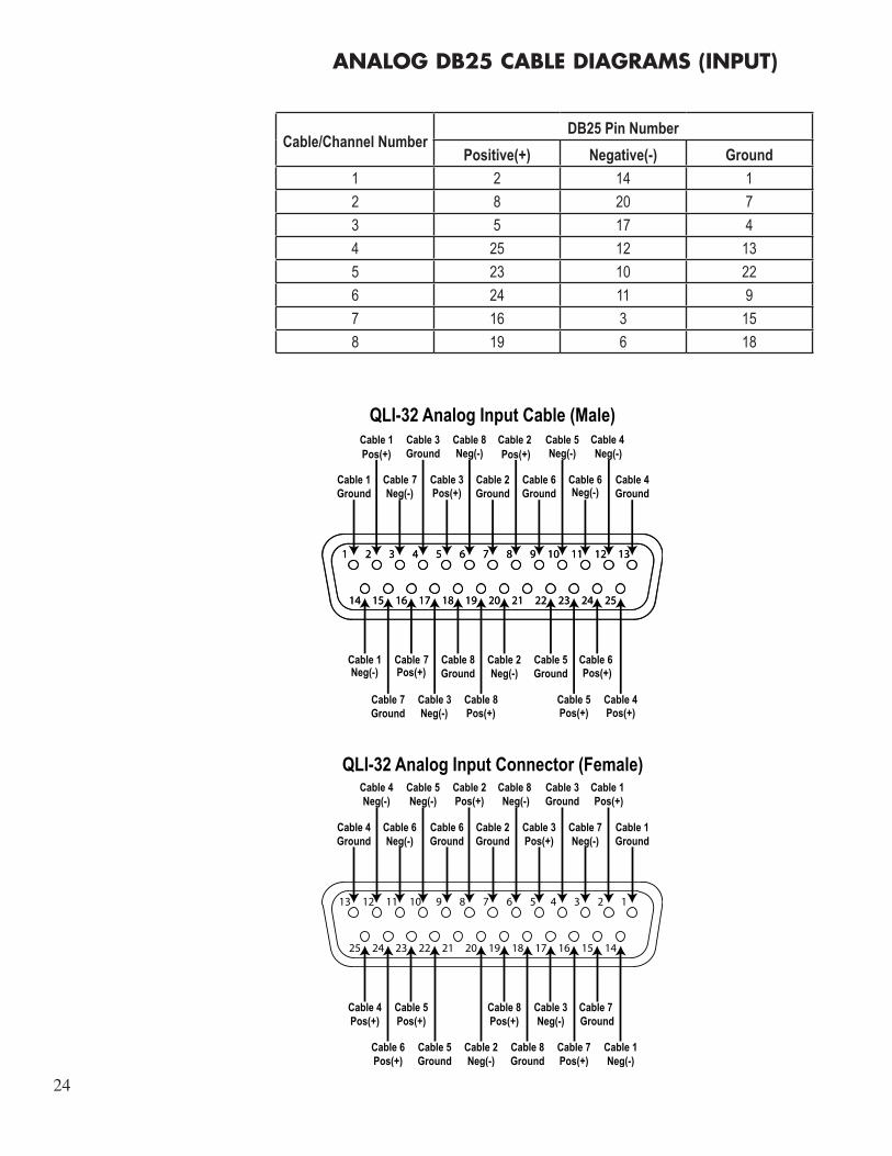
ANALOG DB25 CABLE DIAGRAMS (INPUT)
Cable/Channel NumberDB25 Pin Number
Positive(+) Negative(-) Ground
1 2 14 1
2 8 20 7
3 5 17 4
4 25 12 13
5 23 10 22
6 24 11 9
7 16 3 15
8 19 6 18
13121110987654321
252423222120191817161514
7 8
87
7
8
QLI-32 Analog Input Cable (Male)
Pos(+) Pos(+)
Neg(-) Pos(+)
Neg(-) Neg(-) Neg(-)
Neg(-)
Neg(-) Pos(+)
Neg(-) Pos(+) Pos(+) Pos(+)
Pos(+)Neg(-)
12345678910111213
141516171819202122232425
Cable 2Pos(+)
Cable 3Ground
Cable 6Ground
Cable 3Pos(+)
Cable 2Ground
Cable 7Neg(-)
Cable 8Ground
Cable 5Ground
Cable 7Pos(+)
Cable 7 Ground
Cable 3Neg(-)
Cable 1Neg(-)
Cable 2Neg(-)
Cable 8Pos(+)
QLI-32 Analog Input Connector (Female)Cable 1 Pos(+)
Cable 8 Neg(-)
Cable 5Neg(-)
Cable 1Ground
Cable 4Neg(-)
Cable 4Ground
Cable 6Neg(-)
Cable 6Pos(+)
Cable 4Pos(+)
Cable 5Pos(+)

25
AES/EBU RJ-45 CONNECTOR DIAGRAM
Jack RJ-45 pin AES/EBU Signal
Top
1 1/2+
2 1/2-
3 3/4+
4 5/6+
5 5/6-
6 3/4-
7 7/8+
8 7/8-
Bottom
1 9/10+
2 9/10-
3 11/12+
4 13/14+
5 13/14-
6 11/12-
7 15/16+
8 15/16-
87654321
87654321
12345678
RJ-45 Connector & Cable Pinout
NOTE:*Only 8 AES/EBU channel inputs can be processed at a time.
26
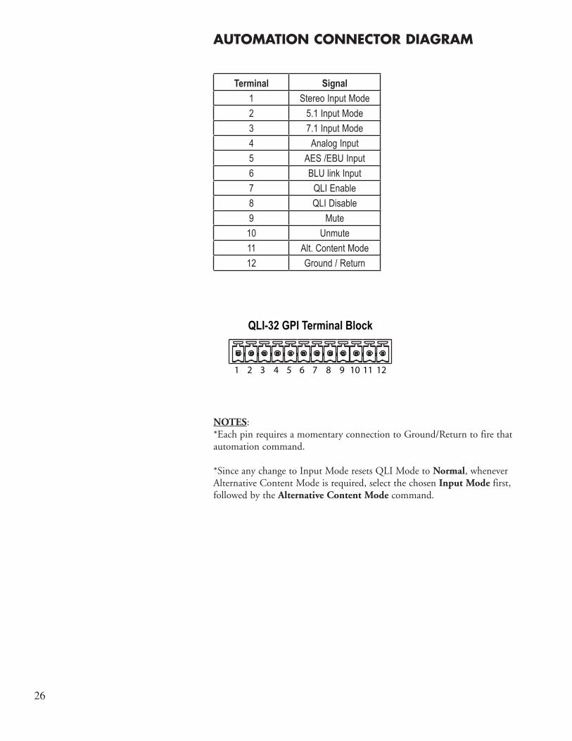
AUTOMATION CONNECTOR DIAGRAM
Terminal Signal
1 Stereo Input Mode
2 5.1 Input Mode
3 7.1 Input Mode
4 Analog Input
5 AES /EBU Input
6 BLU link Input
7 QLI Enable
8 QLI Disable
9 Mute
10 Unmute
11 Alt. Content Mode
12 Ground / Return
NOTES:*Each pin requires a momentary connection to Ground/Return to fire that automation command.
*Since any change to Input Mode resets QLI Mode to Normal, whenever Alternative Content Mode is required, select the chosen Input Mode first, followed by the Alternative Content Mode command.
121110987654321
QLI-32 GPI Terminal Block

27
TCP AUTOMATION COMMANDS
SYSTEM COMMANDS
Read Write
qli32.sys.input qli32.sys.input [analog,aes,blulink]
qli32.sys.mute qli32.sys.mute [0,1]
QLI MODE COMMANDS
Read Write
qli32.sys.qli.mode qli32.sys.qli.mode[normal,altcontent]
qli32.sys.qli.inputmode qli32.sys.qli.inputmode[stereo,5.1,7.1]
qli32.sys.qli.surroundinputlevel qli32.sys.qli.surroundinputlevel [cinema,consumer]
qli32.sys.qli.bypass qli32.sys.qli.bypass [0,1]
TEST COMMANDS
Read Write
qli32.sys.test.speaker_test
qli32.sys.test.speaker_test [(seconds per speaker, number of loops), stop]
NOTE: *Telnet port 10001 required for all commands
*Since any change to Input Mode resets QLI Mode to Normal, whenever Alternative Content Mode is required, select the chosen Input Mode first, followed by the Alternative Content Mode command.
*Some digital cinema servers may need the “\t” tab character in place of spaces and the “\r” return character at the end of command. Ex: “qli32.sys.inputmode\t5.1\r”
8760 South Sandy ParkwaySandy, Utah 84070, U.S.A.Phone: (801)-568-7660 Fax: (801)-568-7662QLI-32 Immersive Processor
Questions or comments?Email us at: [email protected] visit us online at www.lexiconpro.com
Copyright 2015 Lexicon Professional® Part# 184063_RevH
Related Documents