Product Manual 972.931.2728 | 888.972.2728 | www.contemporaryresearch.com

Welcome message from author
This document is posted to help you gain knowledge. Please leave a comment to let me know what you think about it! Share it to your friends and learn new things together.
Transcript
Product Manual
972.931.2728 | 888.972.2728 | www.contemporaryresearch.com
Page | 2 QIP-D IPTV Decoder/Controller Product Manual 072021
Contents
Overview ............................................................................................................................................................................................. 3
Installing the QIP-D ............................................................................................................................................................................. 4
IPTV – Unicast/Multicast ..................................................................................................................................................................... 4
Channel List ......................................................................................................................................................................................... 4
QIP-D Control and Setup ..................................................................................................................................................................... 5
Front Panel Operation ........................................................................................................................................................................ 5
Rear Panel Connections ...................................................................................................................................................................... 6
Setup Notes ......................................................................................................................................................................................... 7
On-Screen Text Communication Menu............................................................................................................................................... 8
On-Screen Graphical A/V Menu .......................................................................................................................................................... 9
HD2-RC IR Remote ............................................................................................................................................................................11
Web Pages.........................................................................................................................................................................................12
RS-232/Telnet/UDP Two-Way Communication Protocol .................................................................................................................14
Table of RS-232 Control Commands .................................................................................................................................................15
Response Strings ...............................................................................................................................................................................18
Creating and Loading the Channel List .............................................................................................................................................20
iCC-Net Control Overview .................................................................................................................................................................22
Building an IPTV Based Control System ............................................................................................................................................22
Integrated Display Controller ............................................................................................................................................................24
HDMI CEC Control .............................................................................................................................................................................24
RS-232 Display Control ......................................................................................................................................................................24
iCC-Net Protocol Format ...................................................................................................................................................................26
Command String Protocol .................................................................................................................................................................27
Table of iCC-Net Control Commands ................................................................................................................................................28
Firmware Update ..............................................................................................................................................................................30
Specifications ....................................................................................................................................................................................31
Safety Instructions and Warranty .....................................................................................................................................................33
Page | 3 QIP-D IPTV Decoder/Controller Product Manual 072021
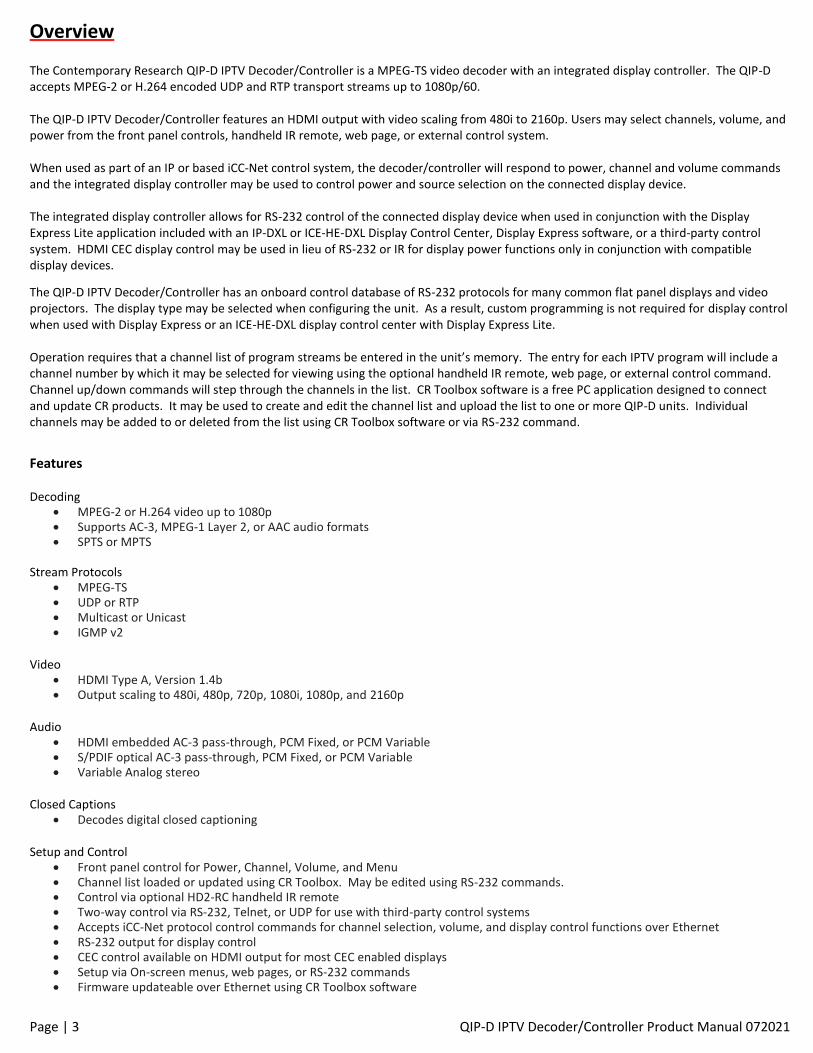
Overview The Contemporary Research QIP-D IPTV Decoder/Controller is a MPEG-TS video decoder with an integrated display controller. The QIP-D accepts MPEG-2 or H.264 encoded UDP and RTP transport streams up to 1080p/60. The QIP-D IPTV Decoder/Controller features an HDMI output with video scaling from 480i to 2160p. Users may select channels, volume, and power from the front panel controls, handheld IR remote, web page, or external control system. When used as part of an IP or based iCC-Net control system, the decoder/controller will respond to power, channel and volume commands and the integrated display controller may be used to control power and source selection on the connected display device. The integrated display controller allows for RS-232 control of the connected display device when used in conjunction with the Display Express Lite application included with an IP-DXL or ICE-HE-DXL Display Control Center, Display Express software, or a third-party control system. HDMI CEC display control may be used in lieu of RS-232 or IR for display power functions only in conjunction with compatible display devices.
The QIP-D IPTV Decoder/Controller has an onboard control database of RS-232 protocols for many common flat panel displays and video projectors. The display type may be selected when configuring the unit. As a result, custom programming is not required for display control when used with Display Express or an ICE-HE-DXL display control center with Display Express Lite. Operation requires that a channel list of program streams be entered in the unit’s memory. The entry for each IPTV program will include a channel number by which it may be selected for viewing using the optional handheld IR remote, web page, or external control command. Channel up/down commands will step through the channels in the list. CR Toolbox software is a free PC application designed to connect and update CR products. It may be used to create and edit the channel list and upload the list to one or more QIP-D units. Individual channels may be added to or deleted from the list using CR Toolbox software or via RS-232 command.
Features Decoding
• MPEG-2 or H.264 video up to 1080p • Supports AC-3, MPEG-1 Layer 2, or AAC audio formats • SPTS or MPTS
Stream Protocols
• MPEG-TS • UDP or RTP • Multicast or Unicast • IGMP v2
Video
• HDMI Type A, Version 1.4b • Output scaling to 480i, 480p, 720p, 1080i, 1080p, and 2160p
Audio
• HDMI embedded AC-3 pass-through, PCM Fixed, or PCM Variable • S/PDIF optical AC-3 pass-through, PCM Fixed, or PCM Variable • Variable Analog stereo
Closed Captions
• Decodes digital closed captioning Setup and Control
• Front panel control for Power, Channel, Volume, and Menu • Channel list loaded or updated using CR Toolbox. May be edited using RS-232 commands. • Control via optional HD2-RC handheld IR remote • Two-way control via RS-232, Telnet, or UDP for use with third-party control systems • Accepts iCC-Net protocol control commands for channel selection, volume, and display control functions over Ethernet • RS-232 output for display control • CEC control available on HDMI output for most CEC enabled displays • Setup via On-screen menus, web pages, or RS-232 commands • Firmware updateable over Ethernet using CR Toolbox software
Page | 4 QIP-D IPTV Decoder/Controller Product Manual 072021
Installing the QIP-D The slim profile of the QIP-D allows for mounting behind a flat panel display. The unit may be attached to the flat panel display with user provided hook and loop fastener adhesive tape or attached to the wall using the mounting ears. The unit may also be set flat on a suitable shelf or other stable flat surface. Connect the HDMI output a video display, video matrix/router, or video encoder. Analog and SPDIF digital audio outputs are available for
connection to an amplifier, audio system processor, or other compatible audio input. Connect the Ethernet port to the IPTV network switch
or directly to the output of an IPTV encoder. The QIP-D will need to be connected to an appropriate power source. The unit may be
powered from a PoE injector or PoE enabled network switch through the Ethernet port or the optional PS12-1.0 power supply.
After the QIP-D is connected, a channel list will need to be uploaded to the unit prior to viewing programs.
IPTV – Unicast/Multicast The QIP-D can receive an IPTV MPEG-TS transport stream that is transmitted as unicast or multicast. Network switch considerations should be based on which method will be implemented.
Unicast Unicast communication is used when the IPTV stream is to be transmitted directly from one encoder to one decoder. Only one decoder can view the content of the IPTV stream at a time. The encoder may be connected to the QIP-D directly or through an unmanaged or managed network switch. This mode is for simple one-to-one communication from the encoder to the decoder. The unicast stream will be received at the IP address specified in the unit’s configuration. The unicast IP address must be different than the unit’s normal IP address. The unicast stream may be SPTS (single program transport stream) or MPTS (multiple program transport stream). Each program will be able to be accessed by direct channel entry or channel up/down.
Multicast Multicast communication allows for an IPTV stream from one or many encoders to be viewed by one or many decoders while minimizing network traffic. Multicast communication requires a Layer 2 managed network switch. The network switch will need to have IGMP snooping enabled. The IPTV stream from the encoders is assigned a unique IP destination address and port in the range reserved for multicast. An IPTV stream is not forwarded by the switch to a decoder until it receives a request from the decoder. Each multicast stream may be SPTS (single program transport stream) or MPTS (multiple program transport stream). The programs will be able to be accessed by direct channel entry or channel up/down.
Channel List A channel list will need to be uploaded to the QIP-D. The channel list will contain a channel number, channel name and related information for each IPTV stream that is to be available for viewing. The available IPTV streams are referenced by the channel number. An IPTV stream may be selected for viewing by entering the associated channel number from the web page, IR remote, or other control source. Channel Up/Down from the front panel, web page, IR remote or other control source will step through the channels entered in the channel list. The channel list can be uploaded through an Ethernet connection using CR Toolbox software, or by a terminal emulator over Telnet or RS-232.
Page | 5 QIP-D IPTV Decoder/Controller Product Manual 072021
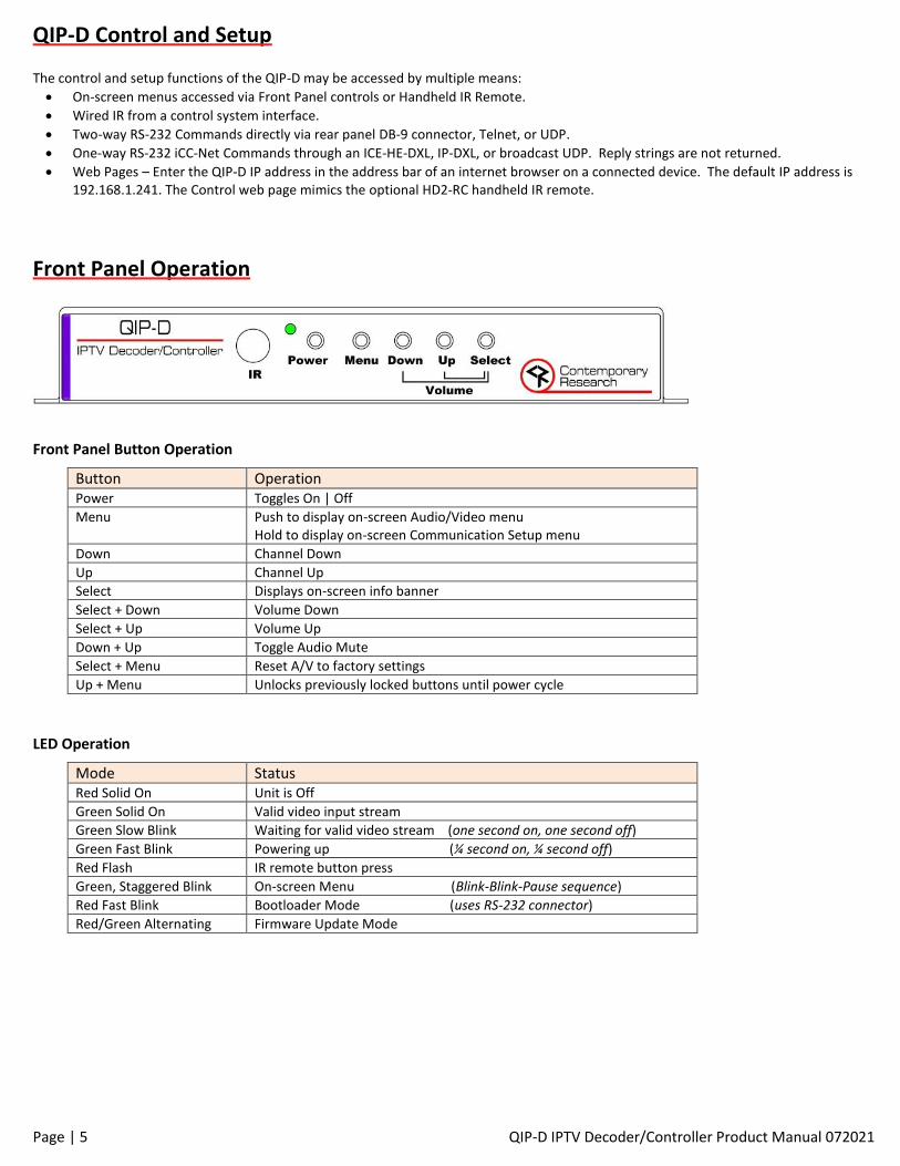
QIP-D Control and Setup The control and setup functions of the QIP-D may be accessed by multiple means:
• On-screen menus accessed via Front Panel controls or Handheld IR Remote.
• Wired IR from a control system interface.
• Two-way RS-232 Commands directly via rear panel DB-9 connector, Telnet, or UDP.
• One-way RS-232 iCC-Net Commands through an ICE-HE-DXL, IP-DXL, or broadcast UDP. Reply strings are not returned.
• Web Pages – Enter the QIP-D IP address in the address bar of an internet browser on a connected device. The default IP address is 192.168.1.241. The Control web page mimics the optional HD2-RC handheld IR remote.
Front Panel Operation
Front Panel Button Operation
Button Operation Power Toggles On | Off
Menu Push to display on-screen Audio/Video menu Hold to display on-screen Communication Setup menu
Down Channel Down
Up Channel Up
Select Displays on-screen info banner
Select + Down Volume Down
Select + Up Volume Up
Down + Up Toggle Audio Mute
Select + Menu Reset A/V to factory settings
Up + Menu Unlocks previously locked buttons until power cycle
LED Operation
Mode Status Red Solid On Unit is Off
Green Solid On Valid video input stream
Green Slow Blink Waiting for valid video stream (one second on, one second off)
Green Fast Blink Powering up (¼ second on, ¼ second off)
Red Flash IR remote button press
Green, Staggered Blink On-screen Menu (Blink-Blink-Pause sequence)
Red Fast Blink Bootloader Mode (uses RS-232 connector)
Red/Green Alternating Firmware Update Mode
Page | 6 QIP-D IPTV Decoder/Controller Product Manual 072021
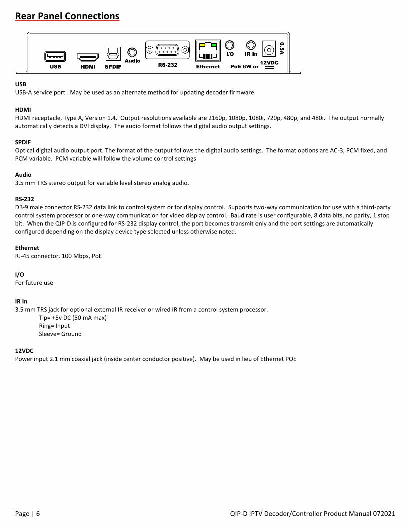
Rear Panel Connections USB USB-A service port. May be used as an alternate method for updating decoder firmware.
HDMI HDMI receptacle, Type A, Version 1.4. Output resolutions available are 2160p, 1080p, 1080i, 720p, 480p, and 480i. The output normally automatically detects a DVI display. The audio format follows the digital audio output settings. SPDIF Optical digital audio output port. The format of the output follows the digital audio settings. The format options are AC-3, PCM fixed, and PCM variable. PCM variable will follow the volume control settings Audio 3.5 mm TRS stereo output for variable level stereo analog audio. RS-232 DB-9 male connector RS-232 data link to control system or for display control. Supports two-way communication for use with a third-party control system processor or one-way communication for video display control. Baud rate is user configurable, 8 data bits, no parity, 1 stop bit. When the QIP-D is configured for RS-232 display control, the port becomes transmit only and the port settings are automatically configured depending on the display device type selected unless otherwise noted. Ethernet RJ-45 connector, 100 Mbps, PoE
I/O For future use
IR In 3.5 mm TRS jack for optional external IR receiver or wired IR from a control system processor. Tip= +5v DC (50 mA max)
Ring= Input Sleeve= Ground
12VDC Power input 2.1 mm coaxial jack (inside center conductor positive). May be used in lieu of Ethernet POE
Page | 7 QIP-D IPTV Decoder/Controller Product Manual 072021
Setup Notes
DVI Compatibility with DVI displays is normally supported and automatically detected. Forced DVI mode may be manually selected from the HDMI-DVI menu setting in the A/V web page or by RS-232 command.
Audio The volume settings do not affect digital audio in AC-3 or PCM modes. PCM Variable supports volume control on all audio outputs. The analog audio outputs always follow the volume control settings. If there is no audio, make sure the volume is up (and not muted). A “motorboat” sound means the display does not support AC-3, and the mode should be changed to PCM.
IR Control • Interference from room fluorescent lights can cause problems with IR remote operation. If this occurs, the frequency of the IR may
be changed in the HD2-RC remote. Hold Select and press “9” to set the IR frequency at 57 KHz. Hold Select and press “4” to set the IR to the normal 38 KHz frequency.
• Rear panel IR input jack for use with IR-RXD (5034-001) external IR receiver or equivalent
• If there is significant IR interference, an IR-RXD Remote Sensor may be required. Cover the front-panel IR sensor to reduce interference.
• Disabling the IR sensor in the configuration settings will also disable the rear panel IR input jack.
• The QIP-D will respond to a universal remote with the TV type set to Sharp.
RS-232 Control Port Depending on the application, the RS-232 port may be configured for one-way or full two-way communication. For installations which the QIP-D will be used for display device control, the RS-232 port will be transmit only. Control strings will be sent to the display, but the unit will not respond to any response data on the receive pin from the display. The RS-232 Data LED however will flash green when data is received which may be useful for troubleshooting purposes. Two-way communication will allow for full control of the QIP-D from a third-party control system processor when display control is not desired. To configure the RS-232 port for one-way communication, an RS-232 display device type must be entered when configuring the QIP-D. Codes for the display device types are listed on page 25. To configure the RS-232 port for two-way communication, enter 0 for the Display Device Type.
Network Addressing Although the unit has only one physical Ethernet connection, internally there are two network interfaces. Traffic to each interface is automatically managed. The primary network interface is for communication, control, and firmware updates and will have the IP address assigned to the unit. The second network interface is for the IPTV traffic. The IP address used by the second network interface is dynamic and will change according to the destination address of the IPTV stream that is viewed. For viewing a unicast IPTV stream, the interface will use the Unicast Destination Address that is entered when configuring the unit. When viewing a multicast IPTV stream, the IP address of the second interface is assigned automatically. If no unicast IPTV stream is in the channel list, it is best practice to set the Unicast Destination Address to the default setting of 000.000.000.000. An IP address in the reserved range will be assigned and an entry of 24:12:34:xx:xx:xx will appear in the MAC table of a network switch. This should prevent any potential unintended IP address conflicts.
Restore Factory Default Settings The unit may have the configuration restored to the factory default settings. The factory default settings may be restored using the on-screen text menu. Hold the Menu button to open the on-screen text menu. Select the System menu and scroll to Firmware. Verify that the System firmware is displayed. Press Select to bring up the blinking cursor. Simultaneously press Power and Up to restore the default settings. The factory default settings may also be restored via the RS-232 command ‘>Z!’. Note that the RS-232 port settings will be changed if different than the default and the RS-232 communication will be lost.
Page | 8 QIP-D IPTV Decoder/Controller Product Manual 072021
On-Screen Text Communication Menu The on-screen communication menu may be accessed by holding the Menu button on the front panel or handheld IR remote. The action may be emulated from a control system processor via the wired IR input.
On-Screen Setup Menu Button Operation
Button Function Power Exit OSD Menu Mode
Menu Hold to enter OSD Menu Mode Push to exit OSD Menu Mode
Down Next menu item
Up Previous menu item
Select Data Entry Mode See table below
Data Entry Mode Button Operation
Button Function Menu Go to previous field or back to Menu
Up / Down Change selected data
Select Go to next field or save selected data and go back to Menu
On-Screen Communication Settings
Button Function IP Address 192.168.1.241
IP Mode Select Static |DHCP Gateway and Subnet Mask settings remain when toggled from DHCP to Static
Gateway 192.168.1.1 Automatic for DHCP. Use Menu/Select and Up/Down arrows to manually set a static address, Select saves after the last entry.
Subnet Mask 255.255.255.0 Telnet Port 0023 (1 – 16535)
Unicast DstAddr Sets the unicast destination address
Device Number Enter device number (1 - 4000)
TV Control Type See Control Type list and enter the required number (1 – 99)
IR Receive On | Off
Versions Firmware versions Press Select, then Up/Down to scroll through versions QIP-D V2.04 – System Firmware HW Rev D0 – Hardware Version Boot Ldr V1.02 – Bootloader Version Decoder V1.22 – Decoder Firmware
Page | 9 QIP-D IPTV Decoder/Controller Product Manual 072021
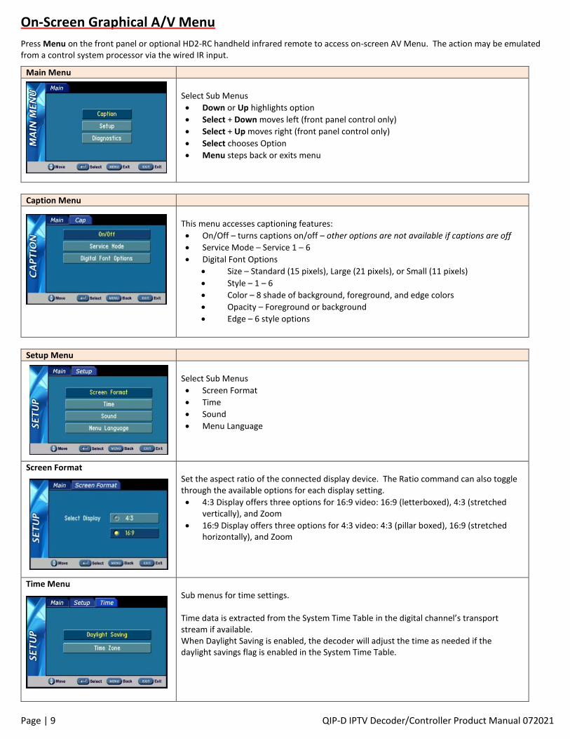
On-Screen Graphical A/V Menu
Press Menu on the front panel or optional HD2-RC handheld infrared remote to access on-screen AV Menu. The action may be emulated from a control system processor via the wired IR input.
Main Menu
Select Sub Menus
• Down or Up highlights option
• Select + Down moves left (front panel control only)
• Select + Up moves right (front panel control only)
• Select chooses Option
• Menu steps back or exits menu
Caption Menu
This menu accesses captioning features:
• On/Off – turns captions on/off – other options are not available if captions are off
• Service Mode – Service 1 – 6
• Digital Font Options
• Size – Standard (15 pixels), Large (21 pixels), or Small (11 pixels)
• Style – 1 – 6
• Color – 8 shade of background, foreground, and edge colors
• Opacity – Foreground or background
• Edge – 6 style options
Setup Menu
Select Sub Menus
• Screen Format
• Time
• Sound
• Menu Language
Screen Format
Set the aspect ratio of the connected display device. The Ratio command can also toggle through the available options for each display setting.
• 4:3 Display offers three options for 16:9 video: 16:9 (letterboxed), 4:3 (stretched vertically), and Zoom
• 16:9 Display offers three options for 4:3 video: 4:3 (pillar boxed), 16:9 (stretched horizontally), and Zoom
Time Menu
Sub menus for time settings. Time data is extracted from the System Time Table in the digital channel’s transport stream if available. When Daylight Saving is enabled, the decoder will adjust the time as needed if the daylight savings flag is enabled in the System Time Table.
Page | 10 QIP-D IPTV Decoder/Controller Product Manual 072021
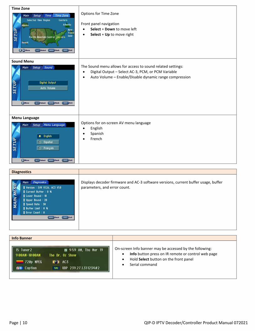
Time Zone Options for Time Zone Front panel navigation
• Select + Down to move left
• Select + Up to move right
Sound Menu
The Sound menu allows for access to sound related settings:
• Digital Output – Select AC-3, PCM, or PCM Variable
• Auto Volume – Enable/Disable dynamic range compression
Menu Language
Options for on-screen AV menu language
• English
• Spanish
• French
Diagnostics
Displays decoder firmware and AC-3 software versions, current buffer usage, buffer parameters, and error count.
Info Banner
On-screen Info banner may be accessed by the following:
• Info button press on IR remote or control web page
• Hold Select button on the front panel
• Serial command
Page | 11 QIP-D IPTV Decoder/Controller Product Manual 072021
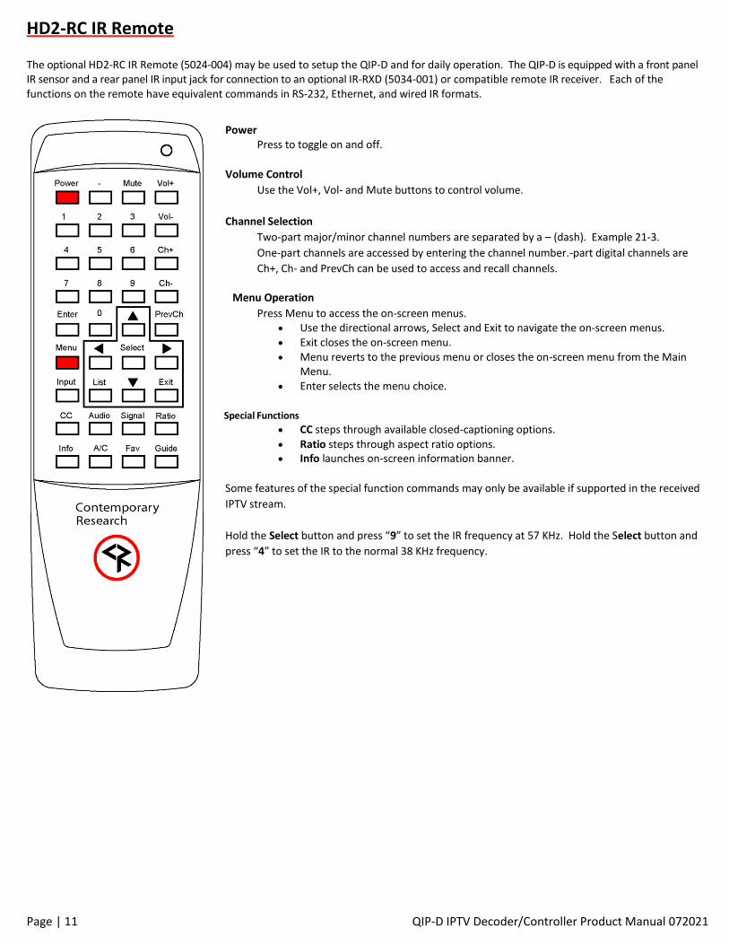
HD2-RC IR Remote The optional HD2-RC IR Remote (5024-004) may be used to setup the QIP-D and for daily operation. The QIP-D is equipped with a front panel IR sensor and a rear panel IR input jack for connection to an optional IR-RXD (5034-001) or compatible remote IR receiver. Each of the functions on the remote have equivalent commands in RS-232, Ethernet, and wired IR formats.
Power Press to toggle on and off.
Volume Control
Use the Vol+, Vol- and Mute buttons to control volume.
Channel Selection
Two-part major/minor channel numbers are separated by a – (dash). Example 21-3.
One-part channels are accessed by entering the channel number.-part digital channels are
Ch+, Ch- and PrevCh can be used to access and recall channels.
Menu Operation
Press Menu to access the on-screen menus. • Use the directional arrows, Select and Exit to navigate the on-screen menus. • Exit closes the on-screen menu. • Menu reverts to the previous menu or closes the on-screen menu from the Main
Menu. • Enter selects the menu choice.
Special Functions
• CC steps through available closed-captioning options. • Ratio steps through aspect ratio options. • Info launches on-screen information banner.
Some features of the special function commands may only be available if supported in the received
IPTV stream.
Hold the Select button and press “9” to set the IR frequency at 57 KHz. Hold the Select button and
press “4” to set the IR to the normal 38 KHz frequency.
Page | 12 QIP-D IPTV Decoder/Controller Product Manual 072021
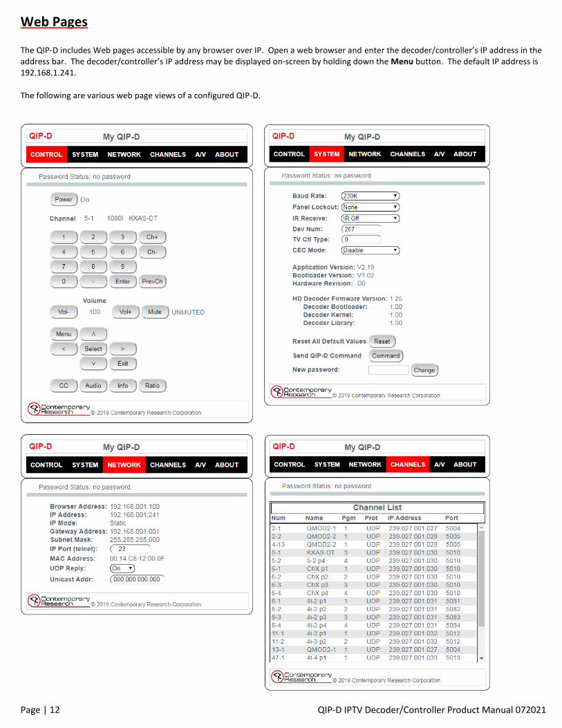
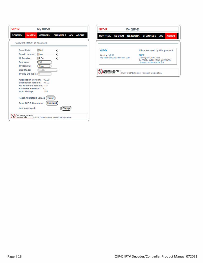
Web Pages The QIP-D includes Web pages accessible by any browser over IP. Open a web browser and enter the decoder/controller’s IP address in the address bar. The decoder/controller’s IP address may be displayed on-screen by holding down the Menu button. The default IP address is 192.168.1.241.
The following are various web page views of a configured QIP-D.
Page | 13 QIP-D IPTV Decoder/Controller Product Manual 072021
Page | 14 QIP-D IPTV Decoder/Controller Product Manual 072021
RS-232/Telnet/UDP Two-Way Communication Protocol The QIP-D full duplex RS-232/Telnet protocol enables a system programmer to control all IPTV decoder/controller functions as well as monitor decoder status. All commands are sent as ASCII strings. No delays between characters or commands are required, as data is interrupt driven and buffered. Communications parameters are 1200 to 230,400 baud, 8 data bits, no parity, and 1 stop bit. Factory default is 9600 baud. All settings are
saved to NVRAM in the decoder. The RS-232 port will accept non-standard control such as voltage that swings from 0 to +5 VDC, commonly
found when IR ports are used to send RS-232 commands.
The same commands can be sent over IP Telnet (up to two sessions) and via UDP to the decoder/controller’s IP address to port 31933 (fixed). The default Telnet port is 23. Setting the Telnet port to 0 disables Telnet communication. UDP responses are disabled by default. UDP responses may be enabled in the web page Network Settings menu or RS-232 command. Responses will be sent to port 31934 at the broadcast IP address of the decoder/controller’s subnet.
General Protocol Specifications Characters in command strings to the QIP-D are common ASCII keyboard characters. Command strings sent to the QIP-D begin with the ASCII > (greater than symbol) as an ‘Attention’ character and end with carriage return - ASCII CR, Hex $0D, or keyboard Enter - as an ‘End-of-command’ character. Responses from the QIP-D begin with the ASCII < (less than symbol) as an ‘Attention’ character and end with a carriage return followed by a line feed - ASCII LF or Hex $0A as an ‘End-of-command’ character. A carriage return is required at the end of each command and is assumed in all examples.
Command String Structure [Attention] [Command] (Parameters) [Return] Attention Single character (>) starts the string Command A two-character command Parameters Added attributes to some commands Return A carriage return ends the command string. ASCII CR, Hex $0D, or keyboard ‘Enter’ may be used in programming. For
simplicity, the programming examples in the manual will not show the ‘CR’.
Command and Status Response Commands can be sent back-to-back at any time without any delay. To allow for rapid, multiple commands, status responses are intentionally delayed by about 125mS, sending the most recent status in response to control commands or user actions.
String Example The example below is a command for a channel change to 6-2 followed by the response string. >TC=6-2 <1TU006Uxx1002x0 The status of a setting may be queried by omitting the = (equals symbol). The following command example queries the 64-step volume level and shows the returned response. >VL <VL=62
Page | 15 QIP-D IPTV Decoder/Controller Product Manual 072021
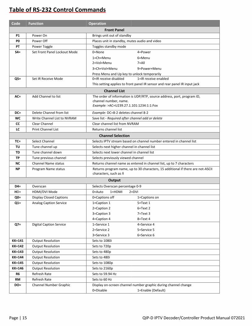
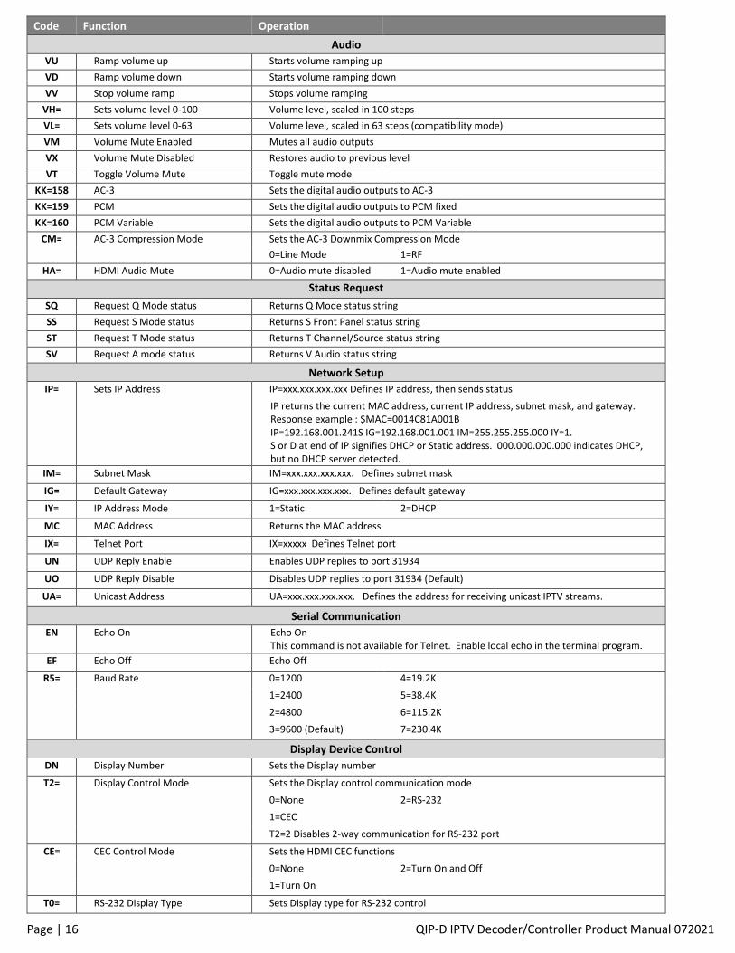
Table of RS-232 Control Commands
Code Function Operation
Front Panel
P1 Power On Brings unit out of standby
P0 Power Off Places unit in standby, mutes audio and video
PT Power Toggle Toggles standby mode
S4= Set Front Panel Lockout Mode 0=None 4=Power
1=Ch+Menu 6=Menu
2=Vol+Menu 7=All
3=Ch+Vol+Menu 9=Power+Menu
Press Menu and Up key to unlock temporarily
Q5= Set IR Receive Mode 0=IR receive disabled 1=IR receive enabled
This setting applies to front panel IR sensor and rear panel IR input jack
Channel List
AC= Add Channel to list The order of information is UDP/RTP, source address, port, program ID, channel number, name. Example: >AC=U239.27.1.101:1234:1:1:Fox
DC= Delete Channel from list Example: DC=8-2 deletes channel 8-2
WC Write Channel List to NVRAM Save list - Required after channel add or delete
CC Clear Channel Clear channel list from NVRAM
LC Print Channel List Returns channel list
Channel Selection
TC= Select Channel Selects IPTV stream based on channel number entered in channel list
TU Tune channel up Selects next higher channel in channel list
TD Tune channel down Selects next lower channel in channel list
TP Tune previous channel Selects previously viewed channel
NC Channel Name status Returns channel name as entered in channel list, up to 7 characters
NP Program Name status Returns program name, up to 30 characters, 15 additional if there are not-ASCII characters, such as ñ
Output
D4= Overscan Selects Overscan percentage 0-9
HD= HDMI/DVI Mode 0=Auto 1=HDMI 2=DVI
Q0= Display Closed Captions 0=Captions off 1=Captions on
Q1= Analog Caption Service 1=Caption 1 5=Text 1
2=Caption 2 6=Text 2
3=Caption 3 7=Text 3
4=Caption 4 8=Text 4
Q7= Digital Caption Service 1=Service 1 4=Service 4
2=Service 2 5=Service 5
3=Service 3 6=Service 6
KK=141 Output Resolution Sets to 1080i
KK=142 Output Resolution Sets to 720p
KK=143 Output Resolution Sets to 480p
KK=144 Output Resolution Sets to 480i
KK=145 Output Resolution Sets to 1080p
KK=146 Output Resolution Sets to 2160p
R6 Refresh Rate Sets to 59.94 Hz
RM Refresh Rate Sets to 60 Hz
DO= Channel Number Graphic Display on-screen channel number graphic during channel change
0=Disable 1=Enable (Default)
Page | 16 QIP-D IPTV Decoder/Controller Product Manual 072021
Code Function Operation
Audio
VU Ramp volume up Starts volume ramping up
VD Ramp volume down Starts volume ramping down
VV Stop volume ramp Stops volume ramping
VH= Sets volume level 0‐100 Volume level, scaled in 100 steps
VL= Sets volume level 0‐63 Volume level, scaled in 63 steps (compatibility mode)
VM Volume Mute Enabled Mutes all audio outputs
VX Volume Mute Disabled Restores audio to previous level
VT Toggle Volume Mute Toggle mute mode
KK=158 AC-3 Sets the digital audio outputs to AC-3
KK=159 PCM Sets the digital audio outputs to PCM fixed
KK=160 PCM Variable Sets the digital audio outputs to PCM Variable
CM= AC-3 Compression Mode Sets the AC-3 Downmix Compression Mode
0=Line Mode 1=RF
HA= HDMI Audio Mute 0=Audio mute disabled 1=Audio mute enabled
Status Request
SQ Request Q Mode status Returns Q Mode status string
SS Request S Mode status Returns S Front Panel status string
ST Request T Mode status Returns T Channel/Source status string
SV Request A mode status Returns V Audio status string
Network Setup
IP= Sets IP Address IP=xxx.xxx.xxx.xxx Defines IP address, then sends status
IP returns the current MAC address, current IP address, subnet mask, and gateway. Response example : $MAC=0014C81A001B IP=192.168.001.241S IG=192.168.001.001 IM=255.255.255.000 IY=1. S or D at end of IP signifies DHCP or Static address. 000.000.000.000 indicates DHCP, but no DHCP server detected.
IM= Subnet Mask IM=xxx.xxx.xxx.xxx. Defines subnet mask
IG= Default Gateway IG=xxx.xxx.xxx.xxx. Defines default gateway
IY= IP Address Mode 1=Static 2=DHCP
MC MAC Address Returns the MAC address
IX= Telnet Port IX=xxxxx Defines Telnet port
UN UDP Reply Enable Enables UDP replies to port 31934
UO UDP Reply Disable Disables UDP replies to port 31934 (Default)
UA= Unicast Address UA=xxx.xxx.xxx.xxx. Defines the address for receiving unicast IPTV streams.
Serial Communication
EN Echo On Echo On This command is not available for Telnet. Enable local echo in the terminal program.
EF Echo Off Echo Off
R5= Baud Rate 0=1200 4=19.2K
1=2400 5=38.4K
2=4800 6=115.2K
3=9600 (Default) 7=230.4K
Display Device Control
DN Display Number Sets the Display number
T2= Display Control Mode Sets the Display control communication mode
0=None 2=RS-232
1=CEC
T2=2 Disables 2-way communication for RS-232 port
CE= CEC Control Mode Sets the HDMI CEC functions
0=None 2=Turn On and Off
1=Turn On
T0= RS-232 Display Type Sets Display type for RS-232 control
Page | 17 QIP-D IPTV Decoder/Controller Product Manual 072021
Code Function Operation
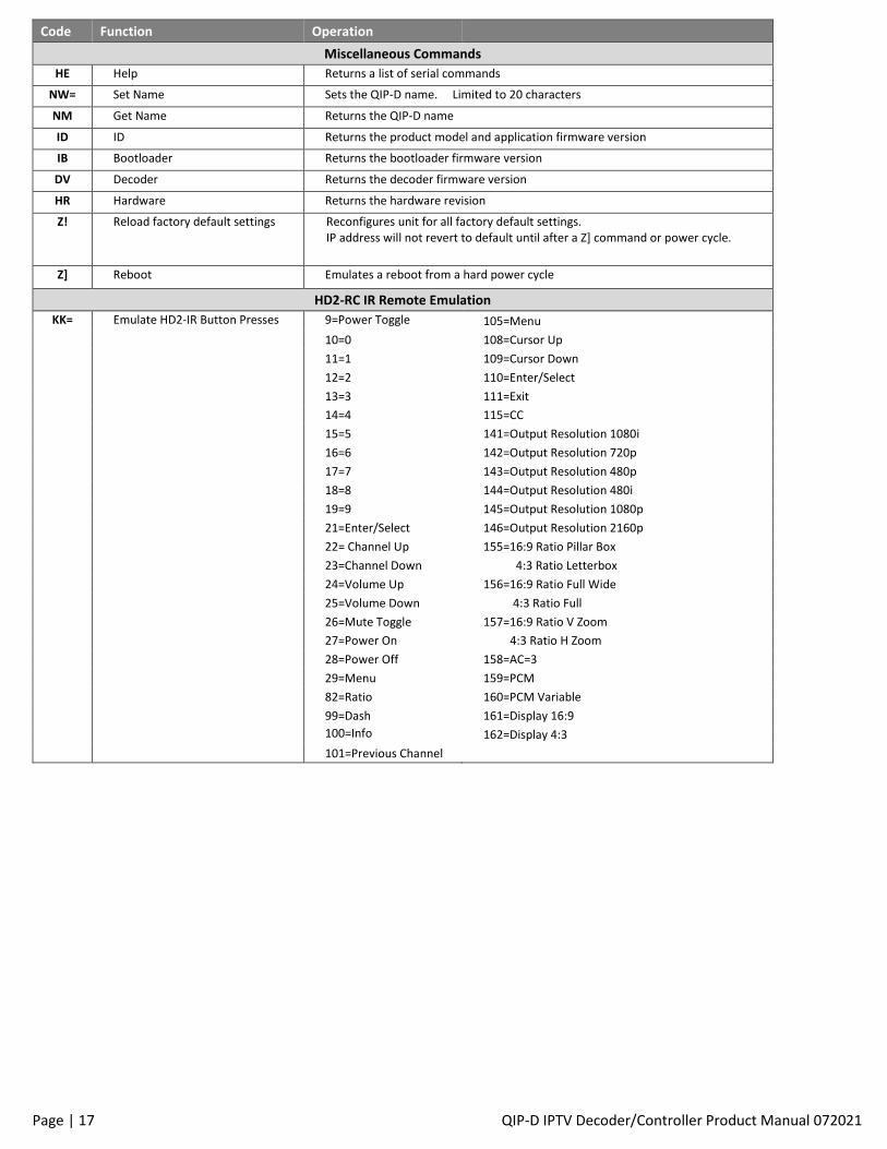
Miscellaneous Commands
HE Help Returns a list of serial commands
NW= Set Name Sets the QIP-D name. Limited to 20 characters
NM Get Name Returns the QIP-D name
ID ID Returns the product model and application firmware version
IB Bootloader Returns the bootloader firmware version
DV Decoder Returns the decoder firmware version
HR Hardware Returns the hardware revision
Z! Reload factory default settings Reconfigures unit for all factory default settings. IP address will not revert to default until after a Z] command or power cycle.
Z] Reboot Emulates a reboot from a hard power cycle
HD2-RC IR Remote Emulation
KK= Emulate HD2-IR Button Presses 9=Power Toggle 105=Menu
10=0 108=Cursor Up
11=1 109=Cursor Down
12=2 110=Enter/Select
13=3 111=Exit
14=4 115=CC
15=5 141=Output Resolution 1080i
16=6 142=Output Resolution 720p
17=7 143=Output Resolution 480p
18=8 144=Output Resolution 480i
19=9 145=Output Resolution 1080p
21=Enter/Select 146=Output Resolution 2160p
22= Channel Up 155=16:9 Ratio Pillar Box
23=Channel Down 4:3 Ratio Letterbox
24=Volume Up 156=16:9 Ratio Full Wide
25=Volume Down 4:3 Ratio Full
26=Mute Toggle 157=16:9 Ratio V Zoom
27=Power On 4:3 Ratio H Zoom
28=Power Off 158=AC=3
29=Menu 159=PCM
82=Ratio 160=PCM Variable
99=Dash 161=Display 16:9
100=Info 162=Display 4:3
101=Previous Channel
Page | 18 QIP-D IPTV Decoder/Controller Product Manual 072021
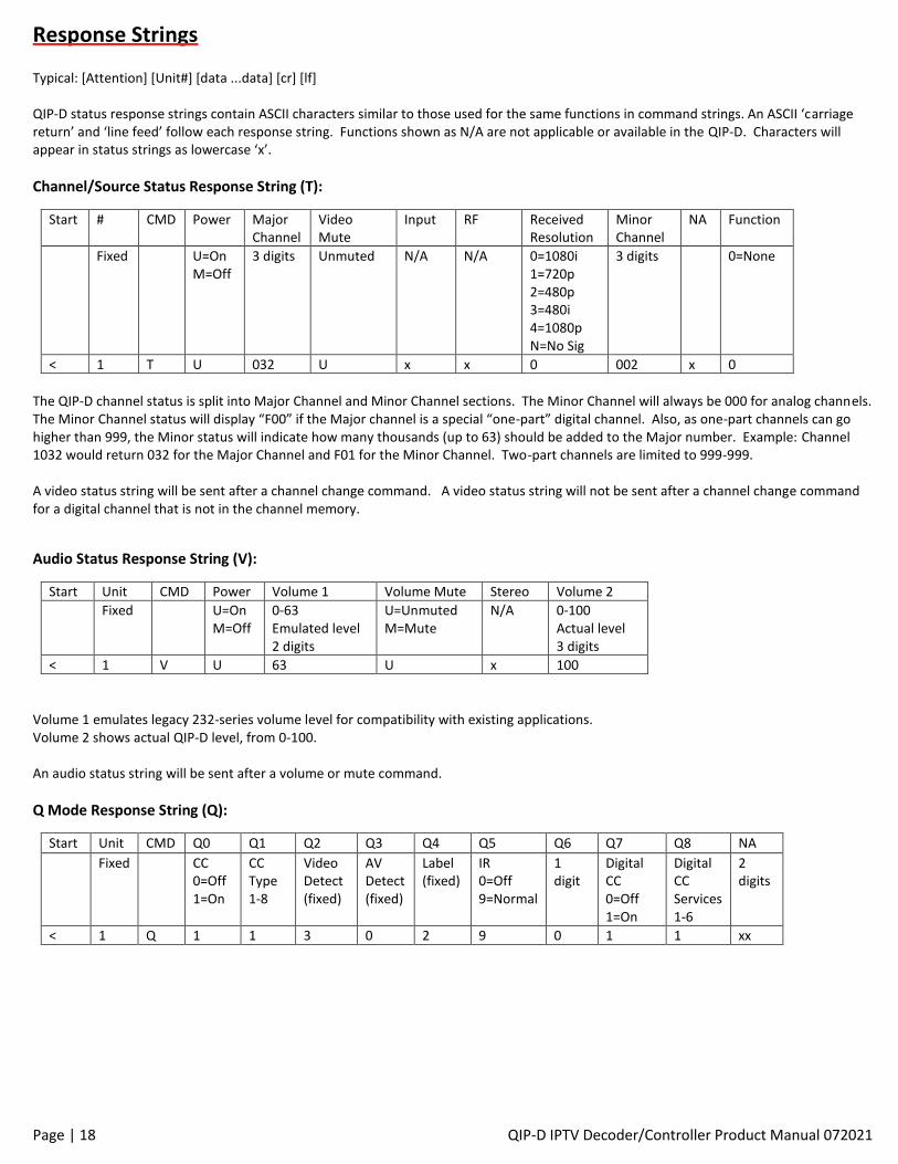
Response Strings Typical: [Attention] [Unit#] [data ...data] [cr] [lf] QIP-D status response strings contain ASCII characters similar to those used for the same functions in command strings. An ASCII ‘carriage return’ and ‘line feed’ follow each response string. Functions shown as N/A are not applicable or available in the QIP-D. Characters will appear in status strings as lowercase ‘x’.
Channel/Source Status Response String (T):
Start # CMD Power Major Channel
Video Mute
Input RF Received Resolution
Minor Channel
NA Function
Fixed U=On M=Off
3 digits Unmuted N/A
N/A 0=1080i 1=720p 2=480p 3=480i 4=1080p N=No Sig
3 digits 0=None
< 1 T U 032 U x x 0 002 x 0
The QIP-D channel status is split into Major Channel and Minor Channel sections. The Minor Channel will always be 000 for analog channels. The Minor Channel status will display “F00” if the Major channel is a special “one-part” digital channel. Also, as one-part channels can go higher than 999, the Minor status will indicate how many thousands (up to 63) should be added to the Major number. Example: Channel 1032 would return 032 for the Major Channel and F01 for the Minor Channel. Two-part channels are limited to 999-999. A video status string will be sent after a channel change command. A video status string will not be sent after a channel change command for a digital channel that is not in the channel memory.
Audio Status Response String (V):
Start Unit CMD Power Volume 1 Volume Mute Stereo Volume 2
Fixed U=On M=Off
0-63 Emulated level 2 digits
U=Unmuted M=Mute
N/A 0-100 Actual level 3 digits
< 1 V U 63 U x 100
Volume 1 emulates legacy 232-series volume level for compatibility with existing applications. Volume 2 shows actual QIP-D level, from 0-100. An audio status string will be sent after a volume or mute command.
Q Mode Response String (Q):
Start Unit CMD Q0 Q1 Q2 Q3 Q4 Q5 Q6 Q7 Q8 NA
Fixed CC 0=Off 1=On
CC Type 1-8
Video Detect (fixed)
AV Detect (fixed)
Label (fixed)
IR 0=Off 9=Normal
1 digit
Digital CC 0=Off 1=On
Digital CC Services 1-6
2 digits
< 1 Q 1 1 3 0 2 9 0 1 1 xx
Page | 19 QIP-D IPTV Decoder/Controller Product Manual 072021
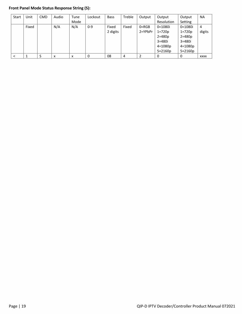
Front Panel Mode Status Response String (S):
Start Unit CMD Audio Tune Mode
Lockout Bass Treble Output Output Resolution
Output Setting
NA
Fixed N/A N/A 0-9 Fixed 2 digits
Fixed 0=RGB 2=YPbPr
0=1080i 1=720p 2=480p 3=480i 4=1080p 5=2160p
0=1080i 1=720p 2=480p 3=480i 4=1080p 5=2160p
4 digits
< 1 S x x 0 08 4 2 0 0 xxxx
Page | 20 QIP-D IPTV Decoder/Controller Product Manual 072021
Creating and Loading the Channel List A list of available channels will need to be uploaded to the QIP-D prior to viewing the IPTV streams. Each channel entry will include UDP/RTP, channel number, IP address and port, program number, and channel name. Each channel’s IP address may be that of a unicast or multicast stream. The list may contain a mix of unicast and multicast addresses. An entry will need to be made for each program of a multiple program transport stream. In the case of a unicast stream, the IP address in the channel list will need to match the unicast address entered in the network menu of the web page, front panel setup menu or by RS-232 command. The unicast address cannot be identical to the IP address of the unit. A channel number is assigned to each IPTV stream and is used for identification. The channel number is used to recall a channel directly either by the optional handheld remote, web page, or a command from a control system processor. One-part and two-part channel numbers are supported. The valid range for one-part channel numbers is 1 to 9999, and the valid range for two-part channel numbers is 1-1 to 999-999. Two-part channel numbers are useful in the situation where an RF encoder/modulator is used as the channel’s source, and the output is set for a simultaneous RF and IP stream. The channel name is limited to seven characters. The channel list may be entered three ways.
• Individual channels may be added using the AC command via the RS-232 serial port or Telnet.
• Individual channels may be added using CR Toolbox software
• A list of channels may be added by creating a text document of the entire channel list and uploading the list using CR Toolbox.
RS-232 A minimum of two command strings are required when adding channels via RS-232. A channel is added using the AC command and stored in NVRAM using the WC command. Multiple channels may be added before sending the WC command. The order of information is UDP/RTP, multicast or unicast address, port, program ID, channel number, name. (A colon separates all fields except UDP/RTP and IP address octets.) The example below shows the command and response strings for adding an new channel to the QIP-D. >AC=U239.27.1.101:1234:1:1:Fox <AC=OK >WC <WC=OK
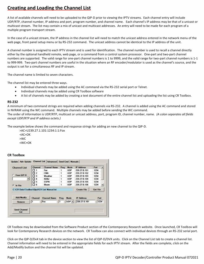
CR Toolbox
CR Toolbox may be downloaded from the Software Product section of the Contemporary Research website. Once launched, CR Toolbox will look for Contemporary Research devices on the network. CR Toolbox can also connect with individual devices through an RS-232 serial port. Click on the QIP-D/DvX tab in the device section to view the list of QIP-D/DVX units. Click on the Channel List tab to create a channel list. Channel information will need to be entered in the appropriate fields for each IPTV stream. After the fields are complete, click on the Add/Modify button and the channel list will be updated.
Page | 21 QIP-D IPTV Decoder/Controller Product Manual 072021
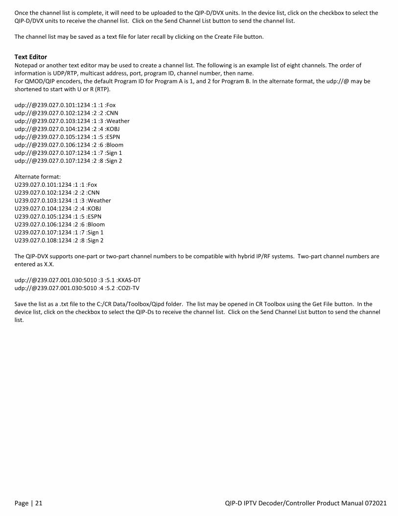
Once the channel list is complete, it will need to be uploaded to the QIP-D/DVX units. In the device list, click on the checkbox to select the QIP-D/DVX units to receive the channel list. Click on the Send Channel List button to send the channel list. The channel list may be saved as a text file for later recall by clicking on the Create File button.
Text Editor Notepad or another text editor may be used to create a channel list. The following is an example list of eight channels. The order of information is UDP/RTP, multicast address, port, program ID, channel number, then name. For QMOD/QIP encoders, the default Program ID for Program A is 1, and 2 for Program B. In the alternate format, the udp://@ may be shortened to start with U or R (RTP). udp://@239.027.0.101:1234 :1 :1 :Fox udp://@239.027.0.102:1234 :2 :2 :CNN udp://@239.027.0.103:1234 :1 :3 :Weather udp://@239.027.0.104:1234 :2 :4 :KOBJ udp://@239.027.0.105:1234 :1 :5 :ESPN udp://@239.027.0.106:1234 :2 :6 :Bloom udp://@239.027.0.107:1234 :1 :7 :Sign 1 udp://@239.027.0.107:1234 :2 :8 :Sign 2 Alternate format: U239.027.0.101:1234 :1 :1 :Fox U239.027.0.102:1234 :2 :2 :CNN U239.027.0.103:1234 :1 :3 :Weather U239.027.0.104:1234 :2 :4 :KOBJ U239.027.0.105:1234 :1 :5 :ESPN U239.027.0.106:1234 :2 :6 :Bloom U239.027.0.107:1234 :1 :7 :Sign 1 U239.027.0.108:1234 :2 :8 :Sign 2 The QIP-DVX supports one-part or two-part channel numbers to be compatible with hybrid IP/RF systems. Two-part channel numbers are entered as X.X. udp://@239.027.001.030:5010 :3 :5.1 :KXAS-DT udp://@239.027.001.030:5010 :4 :5.2 :COZI-TV Save the list as a .txt file to the C:/CR Data/Toolbox/Qipd folder. The list may be opened in CR Toolbox using the Get File button. In the device list, click on the checkbox to select the QIP-Ds to receive the channel list. Click on the Send Channel List button to send the channel list.
Page | 22 QIP-D IPTV Decoder/Controller Product Manual 072021
iCC-Net Control Overview iCC-Net is a unique and proprietary control command protocol from Contemporary Research for sending one-way control commands to display controllers, HDTV tuner/controllers, IPTV decoder/controllers, and HDTV tuners over new or existing video distribution infrastructure. The video distribution system may be for delivery of CATV channels over coax, MPEG-TS IPTV streams delivered over an Ethernet network, or a combination of both. The user will be able to select the channel that is shown on each display as well as control power, volume, and other display related functions. The display controllers, HDTV tuner/controllers and IPTV decoder/controllers will receive an iCC-Net command string and translate it to the IR or RS-232 protocol required for control of the connected video display. The control interface may be a Display Express server, embedded Display Express Lite in an ICE-HE-DXL or IP-DXL display control center, or a third-party control processor. The structure of the iCC-Net command string allows for independent control of over 4000 individual display controllers, HDTV tuner/controllers, IPTV decoder/controllers, and HDTV tuners in any combination. The display controllers, HDTV tuner/controllers, IPTV decoder/controllers, and HDTV tuners will be each configured with a unique display device number. As the command strings are broadcast to all devices on the distribution network, a device will only respond when it receives a command string with a device number value that matches its configured device number. All other devices will drop the command string without responding.
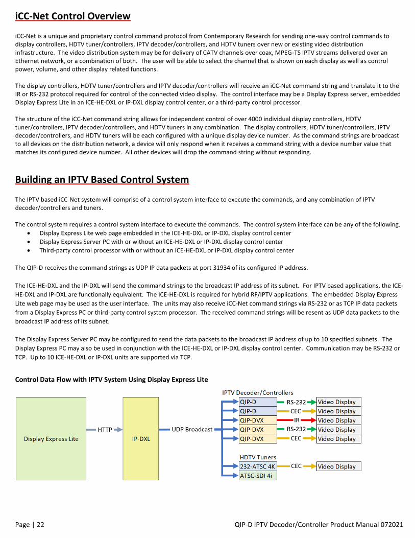
Building an IPTV Based Control System The IPTV based iCC-Net system will comprise of a control system interface to execute the commands, and any combination of IPTV decoder/controllers and tuners. The control system requires a control system interface to execute the commands. The control system interface can be any of the following.
• Display Express Lite web page embedded in the ICE-HE-DXL or IP-DXL display control center
• Display Express Server PC with or without an ICE-HE-DXL or IP-DXL display control center
• Third-party control processor with or without an ICE-HE-DXL or IP-DXL display control center
The QIP-D receives the command strings as UDP IP data packets at port 31934 of its configured IP address.
The ICE-HE-DXL and the IP-DXL will send the command strings to the broadcast IP address of its subnet. For IPTV based applications, the ICE-
HE-DXL and IP-DXL are functionally equivalent. The ICE-HE-DXL is required for hybrid RF/IPTV applications. The embedded Display Express
Lite web page may be used as the user interface. The units may also receive iCC-Net command strings via RS-232 or as TCP IP data packets
from a Display Express PC or third-party control system processor. The received command strings will be resent as UDP data packets to the
broadcast IP address of its subnet.
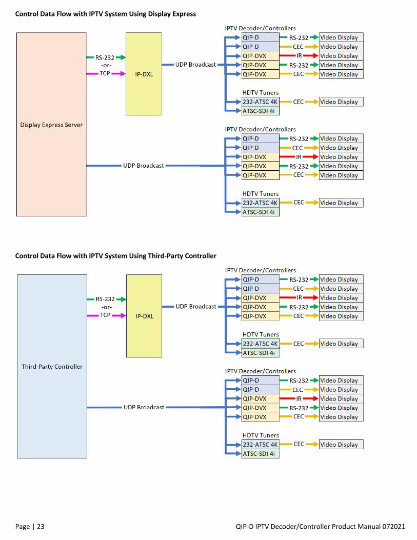
The Display Express Server PC may be configured to send the data packets to the broadcast IP address of up to 10 specified subnets. The
Display Express PC may also be used in conjunction with the ICE-HE-DXL or IP-DXL display control center. Communication may be RS-232 or
TCP. Up to 10 ICE-HE-DXL or IP-DXL units are supported via TCP.
Control Data Flow with IPTV System Using Display Express Lite
Page | 23 QIP-D IPTV Decoder/Controller Product Manual 072021
Control Data Flow with IPTV System Using Display Express
Control Data Flow with IPTV System Using Third-Party Controller
Page | 24 QIP-D IPTV Decoder/Controller Product Manual 072021
Integrated Display Controller The QIP-D supports sending control commands to the connected display using RS-232 or HDMI CEC. The power state of the display will follow the power state of the QIP-D. When used as part of an iCC-Net control system, more display control functions are available. For RS-232 controlled displays, the control functions include power, source selection, and the ability to pass through custom RS-232 strings from the control system. Display control may be enabled in the on-screen text menu, web page, or via RS-232 command. The options are HDMI CEC or RS-232. If RS-232 is selected, two-way RS-232 communication of the QIP-D will be disabled and the RS-232 port will function as transmit only to control the display. The RS-232 protocols for many common TV and display makes and models are built in to the QIP-D application firmware. If a desired display type is not listed, contact Contemporary Research support for assistance.
HDMI CEC Control HDMI CEC may be selected for sending power commands to the display. No other control functions are available for CEC control. HDMI CEC sends standardized control commands over the HDMI cable. CEC functionality is available in many TVs and displays designed for the consumer market. If control of the TV or display via HDMI CEC is desired, it is important to check the TV or display’s documentation to determine if CEC is supported. It is common for manufacturers to use their own unique term to refer to HDMI CEC. For example, Samsung refers to CEC as Anylink. LG refers to it as SimpLink. CEC will likely need to be enabled in the display. Some displays will automatically detect that a CEC supported device has been connected and prompt for confirmation. Although the industry strives for standardization relating to CEC, it is possible that some or all CEC control communication between the ICC1-TC and connected display may not function depending on display make and model. In this situation, RS-232 is recommended for reliable display control.
RS-232 Display Control One-way RS-232 display control is available through the rear panel DB-9 RS-232 port. The RS-232 port may be used to send commands for power and input source selection. When used with Display Express or a third-party control system using iCC-Net protocols, it is possible to forward custom RS-232 strings to the display. The connection to the display should be with an RS-232 null modem cable. Most displays with a 3.5mm RS-232 port are compatible with the optional Contemporary Research CC-COM 3.5 (5061-009) serial cable. Typically, displays from LG with a 3.5mm RS-232 port require a DB-9 male to female null modem adaptor (5061-012) if used with the CC-COM 3.5 serial cable or equivalent. The RS-232 display (TV) type will need to be selected via the on-screen text menu or RS-232 command. Refer to the table for a list of the supported display types. If the desired display type is not listed, contact Contemporary Research support for assistance. The com port parameters will automatically be changed to match the requirements of the selected display type unless otherwise noted.
Page | 25 QIP-D IPTV Decoder/Controller Product Manual 072021
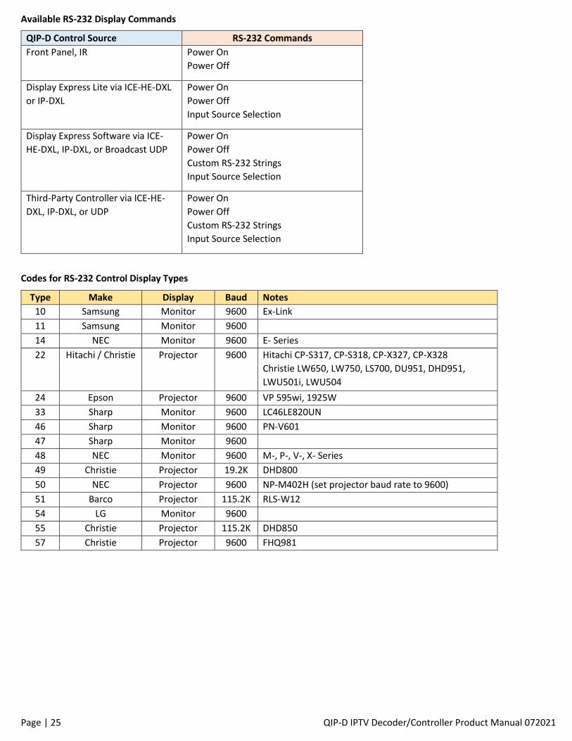
Available RS-232 Display Commands
QIP-D Control Source RS-232 Commands
Front Panel, IR Power On
Power Off
Display Express Lite via ICE-HE-DXL
or IP-DXL
Power On
Power Off
Input Source Selection
Display Express Software via ICE-
HE-DXL, IP-DXL, or Broadcast UDP
Power On
Power Off
Custom RS-232 Strings
Input Source Selection
Third-Party Controller via ICE-HE-
DXL, IP-DXL, or UDP
Power On
Power Off
Custom RS-232 Strings
Input Source Selection
Codes for RS-232 Control Display Types
Type Make Display Baud Notes
10 Samsung Monitor 9600 Ex-Link
11 Samsung Monitor 9600
14 NEC Monitor 9600 E- Series
22 Hitachi / Christie Projector 9600 Hitachi CP-S317, CP-S318, CP-X327, CP-X328
Christie LW650, LW750, LS700, DU951, DHD951,
LWU501i, LWU504
24 Epson Projector 9600 VP 595wi, 1925W
33 Sharp Monitor 9600 LC46LE820UN
46 Sharp Monitor 9600 PN-V601
47 Sharp Monitor 9600
48 NEC Monitor 9600 M-, P-, V-, X- Series
49 Christie Projector 19.2K DHD800
50 NEC Projector 9600 NP-M402H (set projector baud rate to 9600)
51 Barco Projector 115.2K RLS-W12
54 LG Monitor 9600
55 Christie Projector 115.2K DHD850
57 Christie Projector 9600 FHQ981
Page | 26 QIP-D IPTV Decoder/Controller Product Manual 072021
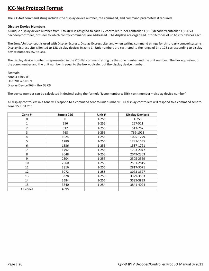
iCC-Net Protocol Format
The iCC-Net command string includes the display device number, the command, and command parameters if required.
Display Device Numbers A unique display device number from 1 to 4094 is assigned to each TV controller, tuner controller, QIP-D decoder/controller, QIP-DVX decoder/controller, or tuner to which control commands are addressed. The displays are organized into 16 zones of up to 255 devices each. The Zone/Unit concept is used with Display Express, Display Express Lite, and when writing command strings for third-party control systems. Display Express Lite is limited to 128 display devices in zone 1. Unit numbers are restricted to the range of 1 to 128 corresponding to display device numbers 257 to 384. The display device number is represented in the iCC-Net command string by the zone number and the unit number. The hex equivalent of the zone number and the unit number is equal to the hex equivalent of the display device number. Example: Zone 3 = hex 03 Unit 201 = hex C9 Display Device 969 = Hex 03 C9 The device number can be calculated in decimal using the formula ‘(zone number x 256) + unit number = display device number’. All display controllers in a zone will respond to a command sent to unit number 0. All display controllers will respond to a command sent to Zone 15, Unit 255.
Zone # Zone x 256 Unit # Display Device #
0 0 1-255 1-255
1 256 1-255 257-511
2 512 1-255 513-767
3 768 1-255 769-1023
4 1024 1-255 1025-1279
5 1280 1-255 1281-1535
6 1536 1-255 1537-1791
7 1792 1-255 1793-2047
8 2048 1-255 2049-2303
9 2304 1-255 2305-2559
10 2560 1-255 2561-2815
11 2816 1-255 2817-3071
12 3072 1-255 3073-3327
13 3328 1-255 3329-3583
14 3584 1-255 3585-3839
15 3840 1-254 3841-4094
All Zones 4095
Page | 27 QIP-D IPTV Decoder/Controller Product Manual 072021
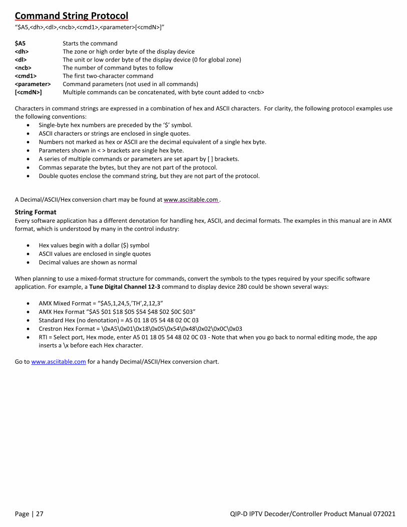
Command String Protocol “$A5,<dh>,<dl>,<ncb>,<cmd1>,<parameter>[<cmdN>]” $A5 Starts the command <dh> The zone or high order byte of the display device <dl> The unit or low order byte of the display device (0 for global zone) <ncb> The number of command bytes to follow <cmd1> The first two-character command <parameter> Command parameters (not used in all commands) [<cmdN>] Multiple commands can be concatenated, with byte count added to <ncb> Characters in command strings are expressed in a combination of hex and ASCII characters. For clarity, the following protocol examples use the following conventions:
• Single-byte hex numbers are preceded by the ‘$’ symbol.
• ASCII characters or strings are enclosed in single quotes.
• Numbers not marked as hex or ASCII are the decimal equivalent of a single hex byte.
• Parameters shown in < > brackets are single hex byte.
• A series of multiple commands or parameters are set apart by [ ] brackets.
• Commas separate the bytes, but they are not part of the protocol.
• Double quotes enclose the command string, but they are not part of the protocol.
A Decimal/ASCII/Hex conversion chart may be found at www.asciitable.com .
String Format Every software application has a different denotation for handling hex, ASCII, and decimal formats. The examples in this manual are in AMX format, which is understood by many in the control industry:
• Hex values begin with a dollar ($) symbol
• ASCII values are enclosed in single quotes
• Decimal values are shown as normal
When planning to use a mixed-format structure for commands, convert the symbols to the types required by your specific software application. For example, a Tune Digital Channel 12-3 command to display device 280 could be shown several ways:
• AMX Mixed Format = “$A5,1,24,5,’TH’,2,12,3”
• AMX Hex Format “$A5 $01 $18 $05 $54 $48 $02 $0C $03”
• Standard Hex (no denotation) = A5 01 18 05 54 48 02 0C 03
• Crestron Hex Format = \0xA5\0x01\0x18\0x05\0x54\0x48\0x02\0x0C\0x03
• RTI = Select port, Hex mode, enter A5 01 18 05 54 48 02 0C 03 - Note that when you go back to normal editing mode, the app inserts a \x before each Hex character.
Go to www.asciitable.com for a handy Decimal/ASCII/Hex conversion chart.
Page | 28 QIP-D IPTV Decoder/Controller Product Manual 072021
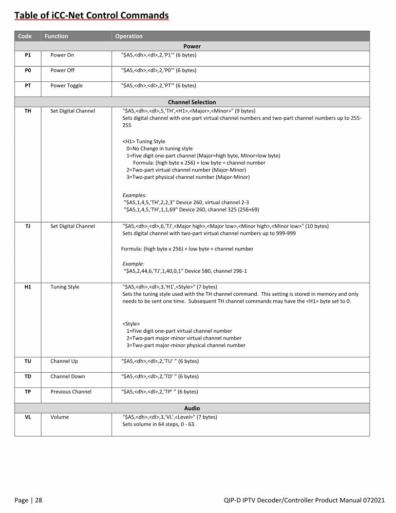
Table of iCC-Net Control Commands
Code Function Operation
Power
P1 Power On "$A5,<dh>,<dl>,2,'P1'" (6 bytes)
P0 Power Off "$A5,<dh>,<dl>,2,'P0'" (6 bytes)
PT Power Toggle "$A5,<dh>,<dl>,2,'PT'" (6 bytes)
Channel Selection
TH Set Digital Channel "$A5,<dh>,<dl>,5,'TH',<H1>,<Major>,<Minor>" (9 bytes) Sets digital channel with one-part virtual channel numbers and two-part channel numbers up to 255-255
<H1> Tuning Style 0=No Change in tuning style 1=Five digit one-part channel (Major=high byte, Minor=low byte) Formula: (high byte x 256) + low byte = channel number 2=Two-part virtual channel number (Major-Minor) 3=Two-part physical channel number (Major-Minor)
Examples: "$A5,1,4,5,'TH',2,2,3" Device 260, virtual channel 2-3 "$A5,1,4,5,'TH',1,1,69" Device 260, channel 325 (256+69)
TJ Set Digital Channel "$A5,<dh>,<dl>,6,'TJ',<Major high>,<Major low>,<Minor high>,<Minor low>" (10 bytes) Sets digital channel with two-part virtual channel numbers up to 999-999
Formula: (high byte x 256) + low byte = channel number
Example: "$A5,2,44,6,'TJ',1,40,0,1" Device 580, channel 296-1
H1 Tuning Style "$A5,<dh>,<dl>,3,'H1',<Style>" (7 bytes) Sets the tuning style used with the TH channel command. This setting is stored in memory and only needs to be sent one time. Subsequent TH channel commands may have the <H1> byte set to 0.
<Style> 1=Five digit one-part virtual channel number 2=Two-part major-minor virtual channel number 3=Two-part major-minor physical channel number
TU Channel Up “$A5,<dh>,<dl>,2,’TU’ ” (6 bytes)
TD Channel Down “$A5,<dh>,<dl>,2,’TD’ ” (6 bytes)
TP Previous Channel “$A5,<dh>,<dl>,2,’TP’ ” (6 bytes)
Audio
VL Volume "$A5,<dh>,<dl>,3,'VL',<Level>" (7 bytes) Sets volume in 64 steps, 0 - 63.
Page | 29 QIP-D IPTV Decoder/Controller Product Manual 072021
Code Function Operation
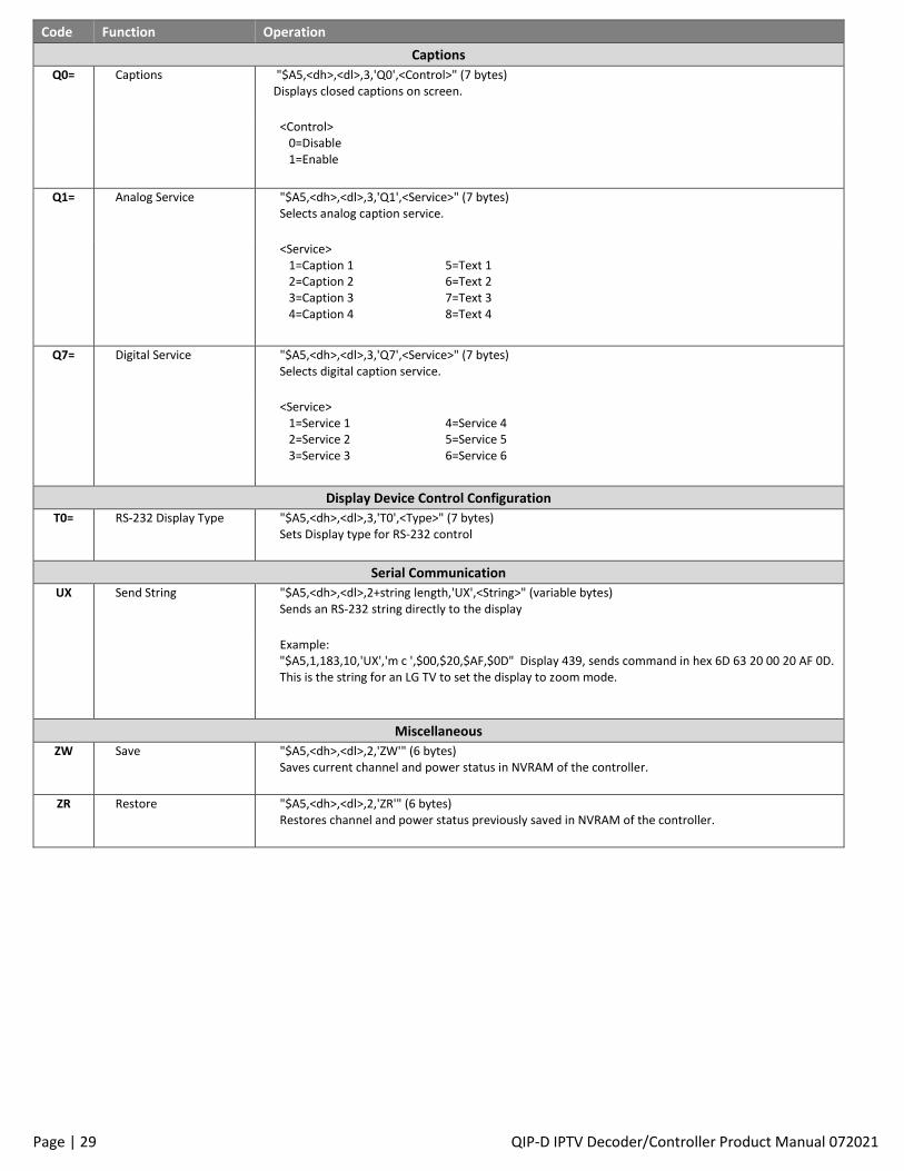
Captions
Q0= Captions "$A5,<dh>,<dl>,3,'Q0',<Control>" (7 bytes) Displays closed captions on screen.
<Control> 0=Disable 1=Enable
Q1= Analog Service "$A5,<dh>,<dl>,3,'Q1',<Service>" (7 bytes) Selects analog caption service.
<Service> 1=Caption 1 2=Caption 2 3=Caption 3 4=Caption 4
5=Text 1 6=Text 2 7=Text 3 8=Text 4
Q7= Digital Service "$A5,<dh>,<dl>,3,'Q7',<Service>" (7 bytes) Selects digital caption service.
<Service> 1=Service 1 2=Service 2 3=Service 3
4=Service 4 5=Service 5 6=Service 6
Display Device Control Configuration
T0= RS-232 Display Type "$A5,<dh>,<dl>,3,'T0',<Type>" (7 bytes) Sets Display type for RS-232 control
Serial Communication
UX Send String "$A5,<dh>,<dl>,2+string length,'UX',<String>" (variable bytes) Sends an RS-232 string directly to the display
Example: "$A5,1,183,10,'UX','m c ',$00,$20,$AF,$0D" Display 439, sends command in hex 6D 63 20 00 20 AF 0D. This is the string for an LG TV to set the display to zoom mode.
Miscellaneous
ZW Save "$A5,<dh>,<dl>,2,'ZW'" (6 bytes) Saves current channel and power status in NVRAM of the controller.
ZR Restore "$A5,<dh>,<dl>,2,'ZR'" (6 bytes) Restores channel and power status previously saved in NVRAM of the controller.
Page | 30 QIP-D IPTV Decoder/Controller Product Manual 072021
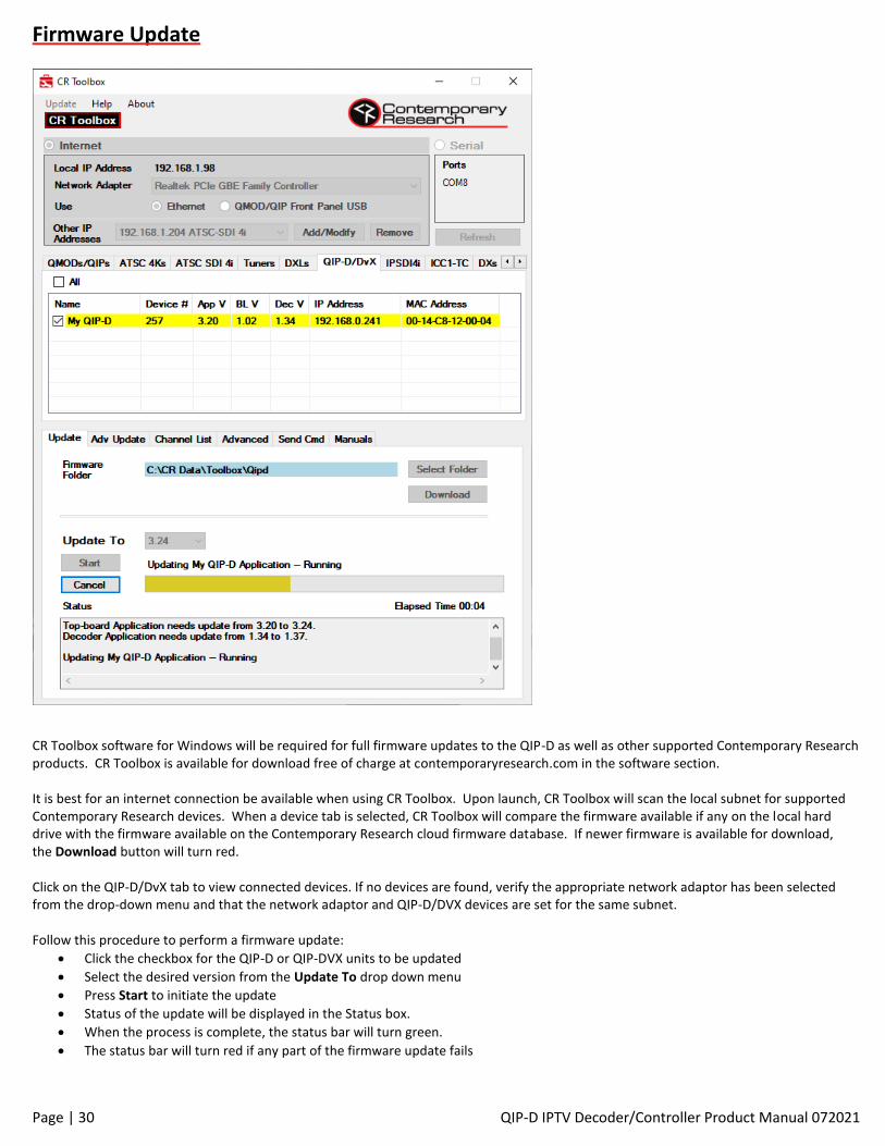
Firmware Update
CR Toolbox software for Windows will be required for full firmware updates to the QIP-D as well as other supported Contemporary Research products. CR Toolbox is available for download free of charge at contemporaryresearch.com in the software section. It is best for an internet connection be available when using CR Toolbox. Upon launch, CR Toolbox will scan the local subnet for supported Contemporary Research devices. When a device tab is selected, CR Toolbox will compare the firmware available if any on the local hard drive with the firmware available on the Contemporary Research cloud firmware database. If newer firmware is available for download, the Download button will turn red. Click on the QIP-D/DvX tab to view connected devices. If no devices are found, verify the appropriate network adaptor has been selected from the drop-down menu and that the network adaptor and QIP-D/DVX devices are set for the same subnet. Follow this procedure to perform a firmware update:
• Click the checkbox for the QIP-D or QIP-DVX units to be updated
• Select the desired version from the Update To drop down menu
• Press Start to initiate the update
• Status of the update will be displayed in the Status box.
• When the process is complete, the status bar will turn green.
• The status bar will turn red if any part of the firmware update fails
Page | 31 QIP-D IPTV Decoder/Controller Product Manual 072021
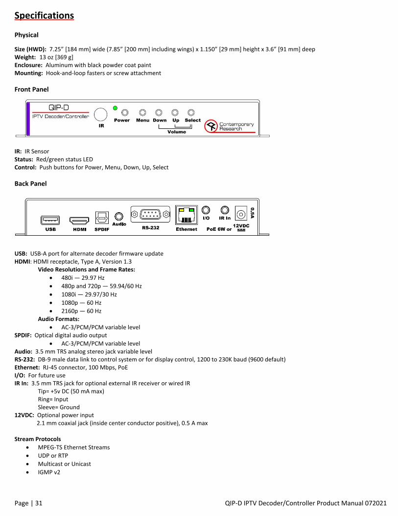
Specifications
Physical
Size (HWD): 7.25” [184 mm] wide (7.85” [200 mm] including wings) x 1.150” [29 mm] height x 3.6” [91 mm] deep Weight: 13 oz [369 g] Enclosure: Aluminum with black powder coat paint Mounting: Hook-and-loop fasters or screw attachment
Front Panel
IR: IR Sensor Status: Red/green status LED Control: Push buttons for Power, Menu, Down, Up, Select
Back Panel
USB: USB-A port for alternate decoder firmware update HDMI: HDMI receptacle, Type A, Version 1.3
Video Resolutions and Frame Rates:
• 480i — 29.97 Hz
• 480p and 720p — 59.94/60 Hz
• 1080i — 29.97/30 Hz
• 1080p — 60 Hz
• 2160p — 60 Hz Audio Formats:
• AC-3/PCM/PCM variable level SPDIF: Optical digital audio output
• AC-3/PCM/PCM variable level Audio: 3.5 mm TRS analog stereo jack variable level RS-232: DB-9 male data link to control system or for display control, 1200 to 230K baud (9600 default) Ethernet: RJ-45 connector, 100 Mbps, PoE I/O: For future use IR In: 3.5 mm TRS jack for optional external IR receiver or wired IR Tip= +5v DC (50 mA max)
Ring= Input Sleeve= Ground
12VDC: Optional power input 2.1 mm coaxial jack (inside center conductor positive), 0.5 A max Stream Protocols
• MPEG-TS Ethernet Streams
• UDP or RTP
• Multicast or Unicast
• IGMP v2
Page | 32 QIP-D IPTV Decoder/Controller Product Manual 072021
Decoding
• Video decoding MPEG-2 (480i, 480p, 720p, 1080i), H.264 (480i, 480p, 720p, 1080i, 1080p)
• Audio decoding AC-3, MPEG-1 Layer or AAC
• Supports single program or multiple program transport streams
• On board closed caption decoder supports EIA-608 and EIA-708 embedded closed captions
Options HD2-RC IR Tuner Remote, 4AAA batteries (5024-004) PS12-1.0 Power Supply (5401-001) IR-RXD External IR Receiver (5034-001) CC-COM-B RS-232 Null Modem Cable (5061-003) CC-COM 3.5 Serial Cable (5061-009)
Trademarks
HDMI, the HDMI logo, and High-Definition Multimedia Interface are trademarks or registered trademarks of HDMI Licensing, LLC
Page | 33 QIP-D IPTV Decoder/Controller Product Manual 072021
Safety Instructions and Warranty
Read before operating equipment.
• Cleaning - Unplug this product from the wall outlet before cleaning. Do not use liquid cleaners or aerosol cleaners. Use a damp cloth for cleaning.
• Power Sources - Use supplied or equivalent UL/CSA approved low voltage DC plug-in transformer.
• Outdoor Antenna Grounding - If you connect an outside antenna or cable system to the product, be sure the antenna or cable system is grounded so as to provide some protection against voltage surges and built-up static charges. Section 810 of the National Electrical Code, ANSI/NFPA No. 70, pro- vides information with respect to proper grounding of the mast and supporting structure, grounding of the lead-in wire to an antenna discharge unit, size of grounding conductors, location of antenna discharge unit, connection to grounding electrodes, and requirements for the grounding electrode.
• Lightning - Avoid installation or reconfiguration of wiring during lightning activity.
• Power Lines - Do not locate an outside antenna system near overhead power lines or other electric light or power circuits or where it can fall into such power lines or circuits. When installing an outside antenna system, refrain from touching such power lines or circuits, as contact with them might be fatal.
• Overloading - Do not overload wall outlets and extension cords as this can result in a risk of fire or electric shock.
• Object and Liquid Entry - Never push objects of any kind into this product through openings as they may touch dangerous voltage points or short out parts, resulting in a fire or electric shock. Never spill liquid of any kind on the product.
• Servicing - Do not attempt to service this product yourself as opening or removing covers may expose you to dangerous voltage or other hazards. Refer all servicing to qualified service personnel.
• Damage Requiring Service - Unplug this product from the wall outlet and refer servicing to qualified service personnel under the following conditions:
o When the power supply cord or plug is damaged.
o If liquid spills or objects fall into the product.
o If the product is exposed to rain or water.
o If the product does not operate normally by following the operating instructions. Adjust only those controls that are
covered by the operating instructions. An improper adjustment of other controls may result in damage and will often require extensive work by a qualified technician to restore the product to its normal operation.
o If the video product is dropped or the cabinet is damaged.
o When the product exhibits a distinct change in performance, this indicates a need for service.
• Heat – This product should be situated away from heat sources such as radiators, heat registers, stoves, or other products (including amplifiers) that produce heat.
Note to CATV system installer: This reminder is provided to call CATV system installer’s attention to Article 820-40 of the National Electrical
Code (Section 54 of Canadian Electrical Code, Part I), that provides guidelines for proper grounding and, in particular, specifies that the cable
ground shall be connected to the grounding system of the building as close to the point of cable entry as possible.
Warranty: Three (3) year limited warranty on all parts and labor for Contemporary Research manufactured products. Contemporary
Research warrants its manufactured products against defects in materials and workmanship for a period of three years from the day of
Page | 34 QIP-D IPTV Decoder/Controller Product Manual 072021
purchase by authorized dealer. If Contemporary Research receives notice of such defects during the warranty period; Contemporary
Research, at its option, will repair or replace products that prove to be defective.
Exclusions: The above warranty shall not apply to defects resulting from improper or inadequate maintenance by the customer, customers
applied software or interfacing, unauthorized modifications or misuse, mishandling, operation outside the normal environmental
specifications for the product, use of the incorrect, modified or extended power supply, acts of God, weather, or improper site operation
and maintenance. Please note Contemporary Research SSV-DX Display Express PC and Luxul Managed Switch products carry a six-month
limited warranty.
Product Service: Contemporary Research will test, repair, or replace the product or products without charge if the unit is under warranty. If
the product is out of warranty, Contemporary Research will test, and then repair the product or products. The parts and labor charge will be
estimated by a technician and confirmed by the customer prior to repair. All components must be returned for testing as a complete unit.
Contemporary Research will not accept responsibility for shipment after it has left the premises.
Technical Support: Contemporary Research technicians will determine and discuss with the customer the criteria for repair and/or
replacement. Contemporary Research Technical Support can be contacted through one of the following resources: e-mail support at
[email protected] or phone at: 972-931-2728
Return Material Authorization (RMA) Number: Before returning a product for repair or replacement, request an RMA from Contemporary
Research’s technical support. Provide tech support with a return phone number, e-mail address, shipping address, product serial numbers
and original purchase order number. Describe the reason for repairs or returns as well as the date of purchase. See the General RMA Terms
and Procedures section for more information. RMA’s are valid for 30 days and will be issued to authorized Contemporary Research dealers
only. End users must return products through authorized Contemporary Research dealers. Include the assigned RMA number in all
correspondence with Contemporary Research. Write the assigned RMA number clearly on the shipping label of the box when returning the
product.
Voided Warranty: The warranty does not apply if the original serial number has been removed or if the product has been disassembled or
damaged through misuse, accident, acts of God, weather, modifications, use of incorrect, modified or extended power supply, or
unauthorized repair.
Shipping and Handling: Contemporary Research will not pay for inbound shipping transportation or insurance charges or accept any responsibility for laws and ordinances from inbound transit. Contemporary Research will pay for outbound shipping, transportation, and insurance charges for all items under warranty, but will not assume responsibility for loss and/or damage by the outbound freight carrier. If the return shipment appears damaged, retain the original boxes and packing material for inspection by the carrier. Contact your carrier immediately. Products not under Warranty: Payment arrangements are required before outbound shipment for all out of warranty products. General RMA Terms and Procedures: RMA’s are valid for 30 days and will be issued only to authorized Contemporary Research dealers only.
• End users must return products through authorized Contemporary Research dealers.
• Before a defective product can be authorized to send in for repair, it must first go through the troubleshooting process with a member of the Contemporary Research Technical Support team.
• Products authorized for repair must have a valid RMA (Return Material Authorization) number.
• Contemporary Research Technical Support will approve the issue of an RMA number.
• An RMA number is to be included in all correspondence with Contemporary Research.
• The RMA number must appear clearly on the shipping label when the product is returned.
• A packing slip must be included on the inside of the box with the RMA number listed and reason for RMA return.
• Products received at Contemporary Research that do not have a valid RMA number clearly marked on the outside of the shipping container may be refused and returned to sender.
• Boxes showing external damage will be refused and sent back to the sender regardless of the clearly marked RMA number and will remain the responsibility of the sender.
Advanced Replacement Policies: For Contemporary Research manufactured products, advance replacement will be provided for “out-of-
the-box” failures up to thirty (30) days after the initial shipment of products.
Shipments of equipment that are refused upon attempted delivery, for any reason, are subject to restocking charges.
Related Documents