QGD-20/25/30 & QGD-40/50 Direct Drive Rotary Screw Air Compressor Parts Manual This manual contains important safety information and should be made available to all personnel who operate and/or maintain this product. Carefully read this manual before attempting to operate or perform maintenance on this equipment. Manual No. 65112-1A May 2009 Edition Update: August 2010

Welcome message from author
This document is posted to help you gain knowledge. Please leave a comment to let me know what you think about it! Share it to your friends and learn new things together.
Transcript
QGD-20/25/30& QGD-40/50
Direct Drive Rotary Screw Air Compressor
Parts Manual
This manual contains important safety information and should be made available to all personnel who operate and/or maintain this product. Carefully read this manual before attempting to operate or perform maintenance on this equipment.
Manual No. 65112-1A
May 2009 Edition
Update: August 2010
bknutson
IESS


Alphabetical Index
Airend (50 hp, 100/125#) ................................................................................................ 8-9
Airend(s) (20/25/30 hp) .................................................................................................... 4-5
Airend(s) (40 hp/50 hp, 150#) ......................................................................................... 6-7
Air Filter ...................................................................................................................... 20-21
Air Piping (20/25/30 hp) ............................................................................................. 44-45
Air Piping (40/50 hp) .................................................................................................. 46-47
Cabinet (20/25/30 hp) ................................................................................................ 62-63
Cabinet (40/50 hp) ..................................................................................................... 64-65
Control Piping (20/25/30 hp) ....................................................................................... 28-39
Control Piping (40/50 hp) ........................................................................................... 40-43
Control Schematics ..................................................................................................... 68-75
Cooler (20/25/30 hp) .................................................................................................. 58-59
Cooler (40/50 hp) ....................................................................................................... 60-61
Decals ......................................................................................................................... 66-67
Drive Coupling ........................................................................................................... 10-11
Electrical Control & Starting (gauge control) ............................................................... 22-27
Electrical Control Diagram (full voltage, auto dual) ..................................................... 76-79
Fluid Piping (20/25/30 hp) (updated 08/10) ............................................................... 50-51
Fluid Piping (40/50 hp) ............................................................................................... 52-53
Fluid Specifications ..............................................................................................................2
Inlet Valves ................................................................................................................. 14-19
Motor Mounting (20/25/30 hp) (updated 11/10/09) .........................................................12
Motor Mounting (40/50 hp) (updated 11/10/09) ..............................................................13
Ordering Replacement Parts ...............................................................................................1
Receiver (20/25/30 hp) ............................................................................................... 48-49
Recommended Spare Parts (updated 12/15/09) .................................................................3
Reservoir (20/25/30 hp) .............................................................................................. 54-55
Reservoir (40/50 hp) ................................................................................................... 56-57
Serial Number Identification ................................................................................................1
Shaft Seal Kit ...............................................................................................................4/6/8
Book Update: 05/01/09all groUps and part nUmBers verified and Updated.
added 50 hp data & receiver option.
Quincy Compressor® - QGD


Serial Number Identification
The serial number tag is located on the top flange of the unit frame just left of the control panel and in the upper right corner of the electrical control panel.
Ordering Replacement Parts
Prompt service can be rendered on replacement part orders if the following information is given:
1. The serial number must be given when ordering replacement parts. Part numbers should be verified per the bill of materials associated with the serial number to ensure that correct replacement parts are ordered.
2. State the exact part number needed. Do not order by index numbers, as index numbers are repeated throughout this manual and if used for ordering parts will necessitate time consuming correspondence.
3. State the exact quantity needed.
4. State the preferred type of transportation.
All replacement parts are to be ordered through an authorized distributor. Insist on Genuine Quincy Parts only! Failure to do so may void your warranty.
Quincy Compressor® - QGD 1

Fluid Specifications
Quincy Compressor® recommends that all Quincy Rotary Screw Products be filled with one of the following QuinSyn® Brand synthetic fluids:
HQuinSyn Plus™H HQuinSyn XP®H
HQuinSyn PG™H HQuinSyn F® (food grade)H
Synthetic fluids other than QuinSyn brand(s) may not be compatible with components used in Quincy Compressor products. If it is deemed necessary to convert a Quincy compressor or vacuum pump to a synthetic other than QuinSyn brand, please contact an authorized Quincy Compressor distributor. To locate your nearest distributor, contact Sales & Marketing in Quincy, Illinois:Phone 217-222-7700, FAX 217-222-4138 or visit our website:http://www.quincycompressor.com.
The following information will be required by the distributor when changing compressor fluid:
Model (circle configuration): ______________________________________________________________________
Serial no. _____________________________________ fluid originally uSed: ____________________________
fluid now uSed (if changed): _____________________ new fluid to Be uSed: ____________________________
Additional information regarding fluid specifications can be found in the Instruction Manual shipped with your unit.
• Fluid Analysis Kit
Quincy Compressor offers free fluid analysis to provide early detection of excessive parts wear, fluid breakdown, or a contaminated fluid system. Order the Fluid Analysis Kit (part no. 128515) from your local authorized Quincy Compressor distributor.
• Fluid Requirements
20, 25 & 30hp - 3.00 gallons 40 hp - 7.50 gallons
horSepower cooling pSiQGD 20 25 30 40 A/C 100 125
2 Quincy Compressor® - QGD
Warning
Guards must be fastened in place before startinG the machine and never removed before disconnectinG and lockinG out the main power supply.
Danger
air in the pipinG from this equipment will cause severe injury or death if used for breathinG air or food processinG (if non-food Grade fluid is used). air used for these processes must meet osha 29cfr1910.134 or fda 21cfr178.3570 standards.
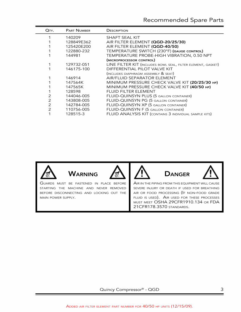
Recommended Spare Parts
Qty. PartNumber DescriPtioN
1 140209 Shaft Seal kit 1 128849e362 aiR filteR element (QgD-20/25/30) 1 125420e200 aiR filteR element (QgD-40/50) 1 122880-232 temPeRatuRe Switch (230°f) (gauge control) 1 144981 temPeRatuRe PRobe-high vibRation, 0.50 nPt (microprocessor control) 1 129732-051 line filteR kit (includes bowl seal, filter element, Gasket) 1 146175-100 diffeRential Pilot valve kit (includes diaphraGm assembly & seat) 1 146914 aiR/fluid SePaRatoR element 1 147564k minimum PReSSuRe check valve kit (20/25/30 hp) 1 147565k minimum PReSSuRe check valve kit (40/50 hp) 1 128598 fluid filteR element 2 144046-005 fluid-QuinSyn PluS (5 Gallon container) 2 143808-005 fluid-QuinSyn Pg (5 Gallon container) 2 142784-005 fluid-QuinSyn XP (5 Gallon container) 2 110756-005 fluid-QuinSyn f (5 Gallon container) 1 128515-3 fluid analySiS kit (contains 3 individual sample kits)
added air filter element part number for 40/50 hp units (12/15/09).
Quincy compressor® - Qgd 3
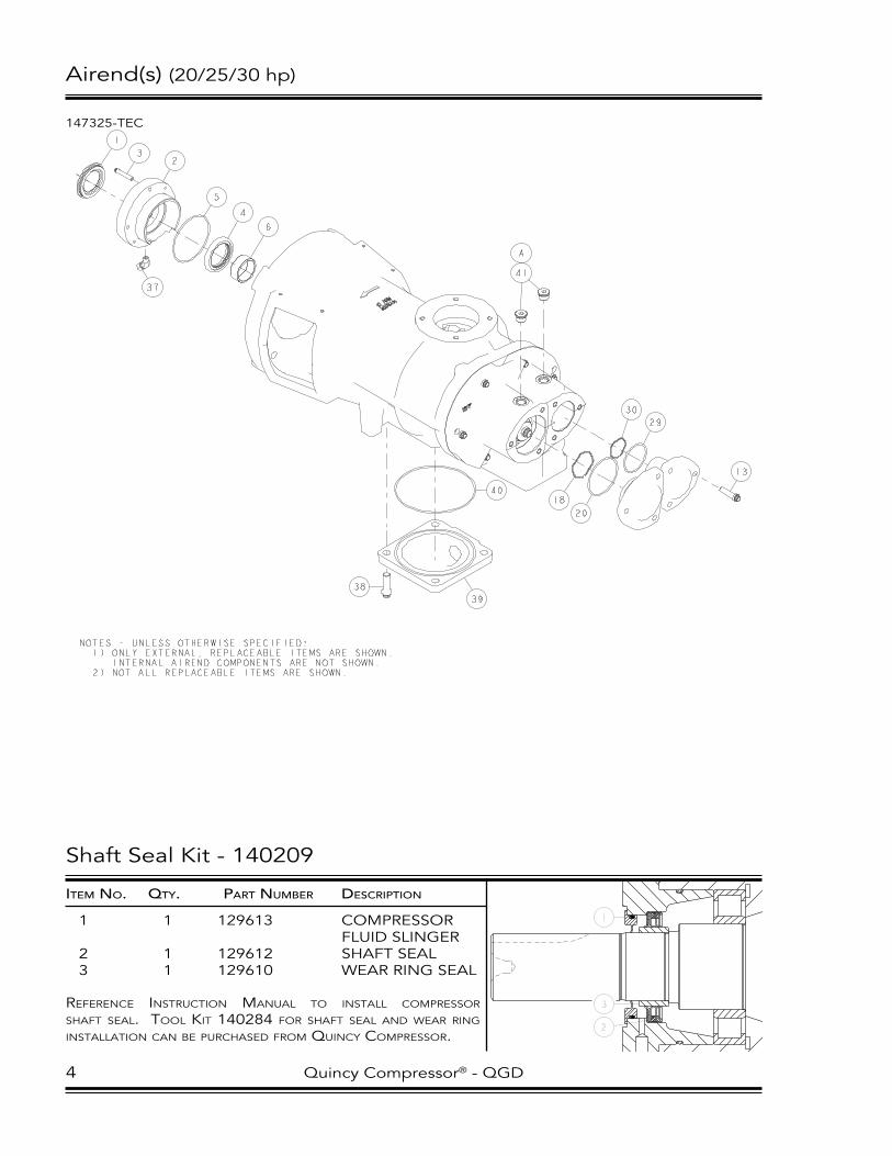
Airend(s) (20/25/30 hp)
147325-TeC
NOTES - UNLESS OTHERWISE SPECIFIED: 1) ONLY EXTERNAL, REPLACEABLE ITEMS ARE SHOWN. INTERNAL AIREND COMPONENTS ARE NOT SHOWN. 2) NOT ALL REPLACEABLE ITEMS ARE SHOWN.
5
1
32
4
6
37
38
39
40
41
A
13
30
18
29
20
Shaft Seal Kit - 140209
itemNo. Qty. PartNumber DescriPtioN
1 1 129613 COMPReSSOR FluID SlINGeR2 1 129612 ShAFT SeAl3 1 129610 weAR RING SeAl
reference inStruction Manual to inStall coMpreSSor Shaft Seal. tool kit 140284 for Shaft Seal and wear ring inStallation can Be purchaSed froM quincy coMpreSSor.
4 Quincy Compressor® - QGD

Airend(s) (20/25/30 hp)
itemNo. Qty. PartNumber DescriPtioN
1 1 129613 COMPReSSOR FluID SlINGeR2 1 129466 SeAl ADAPTeR3 4 90386-J15 COuNTeRBORe SCRew-1/4-20 uNC X 1.50, GRADe 8 (@ 9 ft-lBS)4 1 129612 ShAFT SeAl5 1 22749-154 vITON O-RING-3.75 I.D.6 1 129610 weAR RING SeAl7 * 124232-005 ROTOR BeARING8 * 147323 ROTOR hOuSING9 * 147344-1 MAle ROTOR-120 MM10 * 147345-1 FeMAle ROTOR-101 MM11 1 146895-2 DISChARGe eND PlATe 1 146895-1 DISChARGe eND PlATe (30 hp, 100 & 125 psi)12 2 124145-009 DOwel PIN13 12 90386-l15 COuNTeRBORe SCRew-3/8-16 uNC X 1.50, GRADe 8 (@ 45 ft-lBS, Back off to 25 ft-lBS)14 * 124232-003 ROTOR BeARING15 1 125688 BeARING ReTAINeR16 * 129963-026 ROTOR BeARING17 * 129963-022 ROTOR BeARING18 1 141973-08 SPRING19 ** 146838 DISChARGe CAP ShIM-TeMPeReD STeel20 1 22749-151 vITON O-RING-3.00 I.D.21 1 146834 DISChARGe eND CAP22 1 146836-1 BeARING ReTAINeR23 2 141747-N15 COuNTeRBORe SCRew-1/2-20 uNF X 1.50, GRADe 8 (@ 90 ft-lBS)24 ** 146617 ROTOR ShIM-TeMPeReD STeel25 ** 146977 ROTOR ShIM-TeMPeReD STeel26 1 146836-2 BeARING ReTAINeR27 1 146835 DISChARGe eND CAP28 ** 146839 DISChARGe CAP ShIM-TeMPeReD STeel29 1 22749-140 vITON O-RING-2.25 I.D.30 1 141973-09 SPRING31 * 129963-027 ROTOR BeARING32 * 129963-028 ROTOR BeARING33 1 22749-169 vITON O-RING-7.50 I.D.34 2 140675-004 vITON O-RING/FACe SeAl-0.61 I.D.35 1 129964-150 INTeRNAl ReTAINING RING 36 * 128865-002 ROTOR BeARING37 1 128967-001 45° MAle elBOw-0.25 TuBe X 0.12 NPT38 4 90386-N16 COuNTeRBORe SCRew-1/2-13 uNC X 1.75, GRADe 8 (@ 80 ft-lBS)39 1 147111 FluID GAlleRy COveR PlATe40 1 22749-163 vITON O-RING-6.00 I.D.41 2 128883-075 PIPe PluG-3/4-16 (o-ring)
coMponent Maintenance partS
A 2 140406-908 vITON O-RING-0.64 I.D.
* iteMS not Sold Separately, MuSt Be ordered aS a coMplete airend. ** quantity aS required. @ indicateS torque value in foot poundS (luBricated threadS).
Quincy Compressor® - QGD 5

Airend(s) (40 hp/50 hp, 150#) - 146842-003/-103/-004
146842-TC3
NOTES - UNLESS OTHERWISE SPECIFIED: 1) ONLY EXTERNAL REPLACEABLE ITEMS ARE SHOWN. INTERNAL AIREND COMPONENTS ARE NOT SHOWN. 2) NOT ALL REPLACEABLE ITEMS ARE SHOWN.
20 C
24
16
20 C
20 C
27
22
25
20 C
C 20
2623
31
30
17
28
18 A
C 20 A 18
B 19
Shaft Seal Kit - 140209
itemNo. Qty. PartNumber DescriPtioN
1 1 129613 COMPReSSOR FluID SlINGeR2 1 129612 ShAFT SeAl3 1 129610 weAR RING SeAl
reference inStruction Manual to inStall coMpreSSor Shaft Seal. tool kit 140284 for Shaft Seal and wear ring inStallation can Be purchaSed froM quincy coMpreSSor.
6 Quincy Compressor® - QGD

Airend(s) (40 hp/50 hp, 150#) - 146842-003/-103/-004
itemNo. Qty. PartNumber DescriPtioN
1 * 146844-1 ROTOR hOuSING2 2 124145-004 DOwel PIN3 * 124232-002 ROTOR BeARING4 1 129964-003 BeARING ReTAINeR RING5 * 124232-003 ROTOR BeARING6 2 125688 BeARING ReTAINeR7 * 129611 MAle ROTOR-127 MM8 * 142087 FeMAle ROTOR-127 MM9 1 125577-001 DISChARGe PlATe GASKeT10 * 146846 DISChARGe eND hOuSING11 9 90386-l14 COuNTeRBORe SCRew-3/8-16 uNC X 1.25, GRADe 8 (@ 45 ft-lBS, Back off to 25 ft-lBS)12 * 125580-001 ROTOR BeARING-DISChARGe eND13 2 125572 BeARING ReTAINeR14 6 123478-K12 CAP SCRew-5/16-18 uNC X 1.00, GRADe 5 (@ 13 ft-lBS)15 2 125567 DISChARGe eND CAP16 2 22749-151 vITON O-RING-3.00 I.D.17 8 123478-J12 CAP SCRew-1/4-20 uNC X 1.00, GRADe 5 (@ 6 ft-lBS)18 2 128883-044 PIPe PluG-7/16-20 (o-ring)19 1 128883-075 PIPe PluG-3/4-16 (o-ring)20 11 128883-038 PIPe PluG-3/8-24 (o-ring)21 1 143019 AIR SeAl22 1 129612 ShAFT SeAl23 1 142658 SeAl ADAPTeR24 1 22749-242 vITON O-RING-4.00 I.D.25 1 129613 COMPReSSOR FluID SlINGeR26 4 90386-K12 COuNTeRBORe SCRew-5/16-18 uNC X 1.00, GRADe 8 (@ 13 ft-lBS)27 1 129610 weAR RING SeAl28 ** 125576 DISChARGe CAP ShIM-TeMPeReD STeel29 ** 125575 ROTOR ShIM-TeMPeReD STeel30 1 121032-6 PIPe NIPPle-BRASS, 0.12 NPT X 2.531 1 125780-002 90° FeMAle elBOw-0.25 TuBe X 0.12 NPT
coMponent Maintenance partS
A 2 140406-904 vITON O-RING-0.35 I.D.B 1 140406-908 vITON O-RING-0.64 I.D.C 11 140406-903 vITON O-RING-0.30 I.D.
* iteMS not Sold Separately, MuSt Be ordered aS a coMplete airend. ** quantity aS required. @ indicateS torque value in foot poundS (luBricated threadS).
Quincy Compressor® - QGD 7
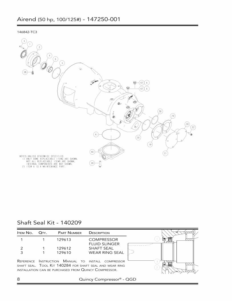
Airend (50 hp, 100/125#) - 147250-001
146842-TC3
NOTES-UNLESS OTHERWISE SPECIFIED: 1) ONLY SOME REPLACEABLE ITEMS ARE SHOWN. NOT ALL REPLACEABLE ITEMS ARE SHOWN. INTERNAL COMPONENTS ARE NOT SHOWN. 2) ITEM A IS A MAINTENANCE PART.
5
41
20
30
3
1
38
2
4
6
39
40
22
28
29
19
21
42 A
42 A
Shaft Seal Kit - 140209
itemNo. Qty. PartNumber DescriPtioN
1 1 129613 COMPReSSOR FluID SlINGeR2 1 129612 ShAFT SeAl3 1 129610 weAR RING SeAl
reference inStruction Manual to inStall coMpreSSor Shaft Seal. tool kit 140284 for Shaft Seal and wear ring inStallation can Be purchaSed froM quincy coMpreSSor.
8 Quincy Compressor® - QGD

Airend (50 hp, 100/125#) - 147250-001
itemNo. Qty. PartNumber DescriPtioN
1 1 129613 COMPReSSOR FluID SlINGeR2 1 129466 SeAl ADAPTeR3 4 90386-J15 COuNTeRBORe SCRew-1/4-20 uNC X 1.50, GRADe 8 (@ 9 ft-lBS)4 1 129612 ShAFT SeAl5 1 22749-154 vITON O-RING-3.75 I.D.6 1 129610 weAR RING SeAl7 * 124232-005 ROTOR BeARING8 * 147251 ROTOR hOuSING9 * 146806-01 MAle ROTOR-143 MM10 * 146807 FeMAle ROTOR-143 MM11 1 147214 DISChARGe eND PlATe12 2 124145-004 DOwel PIN13 6 90386-N17 COuNTeRBORe SCRew-1/2-13 uNC X 2.00, GRADe 8 (@ 75 ft-lBS)14 1 124232-029 ROTOR BeARING15 1 129964-334 INTeRNAl ReTAINING RING 16 * 129963-025 ROTOR BeARING17 * 129963-024 ROTOR BeARING18 1 141973-07 SPRING19 ** 146815 DISChARGe CAP ShIM-TeMPeReD STeel20 1 22749-240 vITON O-RING-3.75 I.D.21 1 146810 DISChARGe eND CAP22 6 90386-l14 COuNTeRBORe SCRew-3/8-16 uNC X 1.25, GRADe 8 (@ 45 ft-lBS, Back off to 25 ft-lBS)23 1 146813 BeARING ReTAINeR24 6 141747-K12 COuNTeRBORe SCRew-5/16-24 uNF X 1.00, GRADe 8 (@ 20 ft-lBS)25 ** 146726 BeARING ADJuSTMeNT ShIM-TeMPeReD STeel26 ** 147591 BeARING ADJuSTMeNT ShIM-TeMPeReD STeel27 1 146814 BeARING ReTAINeR28 1 146811 DISChARGe eND CAP29 ** 146816 DISChARGe CAP ShIM-TeMPeReD STeel30 1 22749-233 vITON O-RING-2.88 I.D.31 1 141973-08 SPRING32 * 129963-022 ROTOR BeARING33 * 129963-023 ROTOR BeARING34 1 22749-268 vITON O-RING-8.50 I.D.35 2 140675-005 vITON O-RING/FACe SeAl-0.74 I.D.36 1 129964-244 INTeRNAl ReTAINING RING 37 * 128865-001 ROTOR BeARING38 1 124393-004 MAle CONNeCTOR-0.25 TuBe X 0.12 NPT39 4 90386-N16 COuNTeRBORe SCRew-1/2-13 uNC X 1.75, GRADe 8 (@ 80 ft-lBS)40 1 147111 FluID GAlleRy COveR PlATe41 1 22749-163 vITON O-RING-6.00 I.D.42 2 128883-075 PIPe PluG-3/4-16 (o-ring)
coMponent Maintenance partS
A 2 140406-908 vITON O-RING-0.64 I.D.
* iteMS not Sold Separately, MuSt Be ordered aS a coMplete airend. ** quantity aS required. @ indicateS torque value in foot poundS (luBricated threadS).
Quincy Compressor® - QGD 9
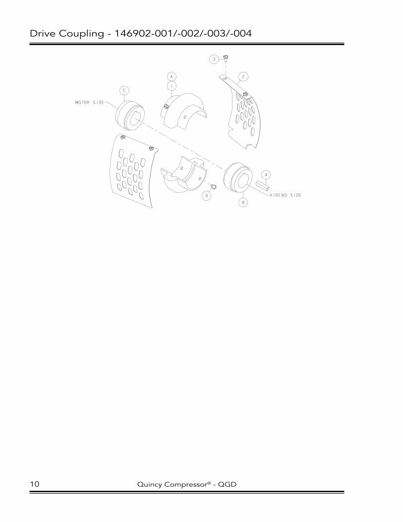
Drive Coupling - 146902-001/-002/-003/-004
2
4
3
1
A
B
C
D AIREND SIDE
MOTOR SIDE
10 Quincy Compressor® - QGD

Drive Coupling - 146902-001/-002/-003/-004
itemNo. Qty. PartNumber DescriPtioN
1 1 128387-100 DRIve COuPlING (20,25 & 30 hp) 1 128387-125 DRIve COuPlING (40 hp, oDp) 1 128387-154 DRIve COuPlING (40 hp, teFc/50 hp)2 2 146820 COuPlING GuARD (20,25 & 30 hp/50 hp, 100/125#) 2 146804 COuPlING GuARD (40 hp/50 hp, 150#)3 4 123478-J09 CAP SCRew-1/4-20 uNC X 0.63, GRADe 5 (@ 6 ft-lBS) (20,25 & 30 hp) 4 123478-J07 CAP SCRew-1/4-20 uNC X 0.50, GRADe 5 (@ 6 ft-lBS) (40 & 50 hp)4 1 20109 ShAFT Key
coMponent Maintenance partS
20/25/30 hp:A 1 128387-400 DRIve COuPlING eleMeNT (1 pair of halveS Sold aS a Matched Set only)B 1 128387-300 COuPlING huB-AIReND SIDe (includeS Set Screw)C 1 128387-200 COuPlING huB-MOTOR SIDe (includeS Set Screw)D 1 128387-500 DRIve COuPlING BOlT KIT (@ 22 ft-lBS, dry threadS)
40/50 hp:A 1 128387-412 DRIve COuPlING eleMeNT (1 pair of halveS Sold aS a Matched Set only)B 1 128387-301 COuPlING huB-AIReND SIDe (includeS Set Screw)C 1 128387-219 COuPlING huB-MOTOR SIDe (includeS Set Screw) (40 hp, oDp) 1 128387-203 COuPlING huB-MOTOR SIDe (includeS Set Screw) (40 hp, teFc/50 hp)D 1 128387-501 DRIve COuPlING BOlT KIT (@ 22 ft-lBS, dry threadS)
@ indicateS torque value in foot poundS (luBricated threadS).
Quincy Compressor® - QGD 11

Motor Mounting (20/25/30 hp) - 146904-001/-002
1
2
34
5
6
7
8
911
10
9
NOTES-UNLESS OTHERWISE SPECIFIED: 1) ITEMS 3 & 4 ARE USED TO ATTACH DRIVE MOTOR TO AIREND HOUSING. 2) SHIPPING SUPPORTS (ITEM 10) ARE TO BE REMOVED AFTER INSTALLATION.
ItemNo. Qty. PartNumber DescrIPtIoN
1 1 147334-02 Motor support (20 hp) 1 147334-01 Motor support (25 & 30 hp)2 2 142201-02 Motor Mount3 4 142578-n15 cap screw-zinc, 1/2-13 unc x 1.50, grade 5 (@ 23 ft-lbs)4 4 123115-08z lockwasher-zinc, 0.505 2 142578-n23 cap screw-zinc, 1/2-13 unc x 3.50, grade 5 (@ 23 ft-lbs)6 2 124370-n02 locknut-1/2-13 unc 7 6 129303r050 fender washer8 2 110428w050 flat washer-0.509 6 14654408020 lock screw-zinc, 8 MM x 20 MM10 2 146942-01 shipping support11 2 141631-n10 cap screw-1/2-13 unc x 0.75, grade 5 (@ 23 ft-lbs)
@ IndIcates torque value In foot pounds (lubrIcated threads).
updated part number for Item 5 (11/10/09).
12 Quincy compressor® - Qgd

Motor Mounting (40/50 hp) - 146937-001/-002/-003
NOTES-UNLESS OTHERWISE SPECIFIED: 1) ITEMS 3 & 4 ARE USED TO ATTACH DRIVE MOTOR TO AIREND HOUSING. 2) ITEM 7 NOT USED IN THIS LOCATION ON 40 HP UNITS WITH ODP MOTORS (UNITS WITH SPACERS). 3) SHIPPING SUPPORT(S) (ITEM 10) TO BE REMOVED AFTER UNIT INSTALLATION. 4) 50 HP, 100 & 125# UNITS USE TWO (2) SUPPORTS, ALL 40 HP UNITS & 50 HP, 150# UNITS USE ONE (1). 4) ITEM 13 (SPACER) USED ONLY ON 40 HP UNITS WITH ODP MOTORS.
1
2
3
4
5
6
7
7
8
9
10 11
12
13
(NOTE 2)
(NOTES 3 & 4)
ItemNo. Qty. PartNumber DescrIPtIoN
1 1 147334-04 Motor support (all 40 hp/50 hp 150#) 1 147334-03 Motor support (50 hp, 100/125#)2 2 142201-02 Motor Mount3 4 142578-n15 cap screw-zinc, 1/2-13 unc x 1.50, grade 5 (@ 23 ft-lbs) (all 40 hp/50 hp 150#)
4 142578-Q15 cap screw-zinc, 5/8-11 unc x 1.50, grade 5 (@ 110 ft-lbs) (50 hp, 100/125#)4 4 123115-08z lockwasher-zinc, 0.50 (all 40 hp/50 hp 150#)
4 123115-10z lockwasher-zinc, 0.63 (50 hp, 100/125#)5 2 142578-n23 cap screw-zinc, 1/2-13 unc x 3.50, grade 5 (@ 23 ft-lbs) (TEFC) 2 142578-n25 cap screw-zinc, 1/2-13 unc x 4.00, grade 5 (@ 23 ft-lbs) (ODp)6 2 124370-n02 locknut-1/2-13 unc 7 * 129303r050 fender washer8 2 110428w050 flat washer-0.509 1 14654408020 lock screw-zinc, 8 MM x 20 MM10 1 146942-02 shipping support (all 40 hp/50 hp 150#)
2 146942-03 shipping support (50 hp, 100/125#)11 * 141631-n10 cap screw-1/2-13 unc x 0.75, grade 5 (@ 23 ft-lbs)12 4 14654412025 lock screw-zinc, 12 MM x 25 MM
4 14654412030 lock screw-zinc, 12 MM x 30 MM13 2 129059-3 Motor spacer (40 hp,ODp Only)
@ IndIcates torque value In foot pounds (lubrIcated threads). * quantIty varIes. reference drawIng notes.
updated part number for Item 5 (11/10/09).
Quincy compressor® - Qgd 13

Inlet valve (20/25/30* hp) - 128900-006/-007
NOTES-UNLESS OTHERWISE SPECIFIED: 1) APPLY LOCTITE 271 TO ITEM 12 AT ASSEMBLY WITH ITEM 13. 2) COAT PRESSURE SIDE OF ITEM 14 WITH E4 (MOLYDISULF) POWDER. 3) ITEM 25 (SPACER) NOT USED ON 25 HP UNITS. 4) COAT ENTIRE OUTSIDE WALL OF SLEEVE (ITEM 19) WITH LOCTITE 609. 5) APPLY TEFLON LUBRICANT TO SEAL (ITEM 14) PRIOR TO INSTALLATION IN CYLINDER. 6) MAKE SURE FLAT PORTION OF SEAL (ITEM 14) IS FACING AWAY FROM CYLINDER.
3
2
5
6
7
825
9
1019
11
12
13
1
17
16
15
8
14
4
23
24
18
20
21
22
14 Quincy Compressor® - QGD
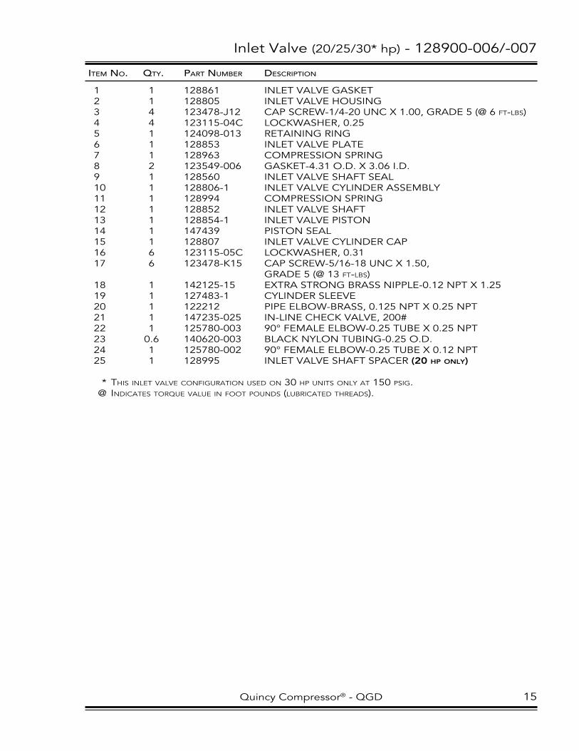
Inlet valve (20/25/30* hp) - 128900-006/-007
itemNo. Qty. PartNumber DescriPtioN
1 1 128861 INleT vAlve GASKeT2 1 128805 INleT vAlve hOuSING3 4 123478-J12 CAP SCRew-1/4-20 uNC X 1.00, GRADe 5 (@ 6 ft-lBS)4 4 123115-04C lOCKwASheR, 0.255 1 124098-013 ReTAINING RING 6 1 128853 INleT vAlve PlATe7 1 128963 COMPReSSION SPRING8 2 123549-006 GASKeT-4.31 O.D. X 3.06 I.D.9 1 128560 INleT vAlve ShAFT SeAl10 1 128806-1 INleT vAlve CylINDeR ASSeMBly11 1 128994 COMPReSSION SPRING12 1 128852 INleT vAlve ShAFT13 1 128854-1 INleT vAlve PISTON14 1 147439 PISTON SeAl15 1 128807 INleT vAlve CylINDeR CAP16 6 123115-05C lOCKwASheR, 0.3117 6 123478-K15 CAP SCRew-5/16-18 uNC X 1.50, GRADe 5 (@ 13 ft-lBS)18 1 142125-15 eXTRA STRONG BRASS NIPPle-0.12 NPT X 1.2519 1 127483-1 CylINDeR Sleeve20 1 122212 PIPe elBOw-BRASS, 0.125 NPT X 0.25 NPT21 1 147235-025 IN-lINe CheCK vAlve, 200#22 1 125780-003 90° FeMAle elBOw-0.25 TuBe X 0.25 NPT23 0.6 140620-003 BlACK NylON TuBING-0.25 O.D.24 1 125780-002 90° FeMAle elBOw-0.25 TuBe X 0.12 NPT25 1 128995 INleT vAlve ShAFT SPACeR (20 hp only)
* thiS inlet valve configuration uSed on 30 hp unitS only at 150 pSig. @ indicateS torque value in foot poundS (luBricated threadS).
Quincy Compressor® - QGD 15

Inlet valve (30 hp, full voltage) - 146952
2
3
9
13
15
16
17
19
14
8
21
22
20
12
11
18
1
10
7
6
5
16 Quincy Compressor® - QGD

Inlet valve (30 hp, full voltage) - 146952
itemNo. Qty. PartNumber DescriPtioN
1 1 127202 INleT vAlve ShAFT2 1 143127 INleT vAlve hOuSING ASSeMBly3 4 142578-N15 CAP SCRew-zINC, 1/2-13 uNC X 1.50, GRADe 5 (@ 23 ft-lBS)4 1 20075 INleT vAlve GASKeT5 1 143128 INleT vAlve PlATe ASSeMBly6 1 125912 vAlve DISC-ByPASS7 1 2134 vAlve GASKeT8 1 123092 SPRING9 1 123157-012 BuNA-N O-RING-0.38 I.D.10 1 127203 vAlve PlATe ReTAINeR11 1 127201 INleT vAlve SPACeR12 1 126460-200 PISTON CuP13 1 124370-l02 lOCKNuT-3/8-16 uNC14 1 126461 INleT vAlve SPRING15 1 126358 INleT vAlve CylINDeR CAP16 3 123115-04z lOCKwASheR-zINC, 0.2517 3 123478-J09 CAP SCRew-1/4-20 uNC X 0.63, GRADe 5 (@ 6 ft-lBS)18 1 126796 INleT vAlve ShAFT SeAl19 4 123115-08z lOCKwASheR-zINC, 0.5020 1 146989 INleT vAlve ADAPTeR21 4 90386-l14 COuNTeRBORe SCRew-3/8-16 uNC X 1.25, GRADe 8 (@ 45 ft-lBS, Back off to 25 ft-lBS)22 1 22749-155 vITON O-RING-4.00 I.D.
@ indicateS torque value in foot poundS (luBricated threadS).
Quincy Compressor® - QGD 17

Inlet valve (30 hp, wye-delta) - 147587 / (40/50 hp) - 126650
NOTE-UNLESS OTHERWISE SPECIFIED: 1) APPLY LOCTITE 609 TO ITEM 15 AT ASSEMBLY WITH ITEM 11.
6
5
3
4
8
9
16
17
10
11
12
1314
15
2
1
22
23
21
19
7
20
18 Quincy Compressor® - QGD

Inlet valve (30 hp, wye-delta) - 147587 / (40/50 hp) - 126650
itemNo. Qty. PartNumber DescriPtioN
1 1 141608 INleT vAlve GASKeT2 4 142578-N15 CAP SCRew-zINC, 1/2-13 uNC X 1.50, GRADe 5 (@ 23 ft-lBS)3 1 126646 INleT vAlve hOuSING4 1 122995 INleT vAlve PlATe ASSeMBly5 1 124368-N02z JAM NuT-1/2-13 uNC, zINC6 1 128720-001 heX heAD SCRew-1/2-13 uNC X 5.00, GRADe 5 (@ 55 ft-lBS)7 1 123092 SPRING8 1 123549-003 GASKeT-6.50 O.D. X 4.56 I.D.9 1 126644 INleT vAlve CylINDeR (includeS BuShing-p/n 22880)10 1 126649 INleT vAlve SPRING11 1 126648 INleT vAlve ShAFT12 1 126647 FlAT wASheR-0.5613 1 126460-350 PISTON CuP14 1 1478-1 FlAT wASheR-0.5215 1 123478-N12 CAP SCRew-1/2-13 uNC X 1.00, GRADe 5 (@ 55 ft-lBS)16 1 126645 INleT vAlve COveR PlATe17 6 123478-l15 CAP SCRew-3/8-16 uNC X 1.50, GRADe 5 (@ 23 ft-lBS)18 1 141258 INleT vAlve GASKeT19 5 123115-08C lOCKwASheR, 0.5020 6 123115-06C lOCKwASheR, 0.3821* 4 90386-l14 COuNTeRBORe SCRew-3/8-16 uNC X 1.25, GRADe 8 (@ 45 ft-lBS, Back off to 25 ft-lBS)22* 1 146989 INleT vAlve ADAPTeR23* 1 22749-155 vITON O-RING-4.00 I.D.
* iteMS 21, 22 & 23 uSed only on 30 hp, wye-delta unitS. @ indicateS torque value in foot poundS (luBricated threadS).
Quincy Compressor® - QGD 19

Air Filter - 146903-001 thru -008
NOTES-UNLESS OTHERWISE SPECIFIED: 1) ITEM 4 (VIBRATION DAMPENER) IS NOT SHOWN. 2) ITEMS 9 & 10 (HOSE AND HOSE CLAMP) ARE USED ONLY ON UNITS W/CABINET.
2
3
5
6
79
10
8
1
20 Quincy Compressor® - QGD

Air Filter - 146903-001 thru -008
itemNo. Qty. PartNumber DescriPtioN
1 1 146929-03 AIR FIlTeR hOuSING TOP (QgD-20/25 & 30, Full voltage) 1 146960 AIR FIlTeR hOuSING ASSeMBly (QgD-30, Wye-Delta) 1 146929-01 AIR FIlTeR hOuSING ASSeMBly (QgD-40/50)2 1 128849e362 AIR FIlTeR eleMeNT (QgD-20/25/30) 1 125420e200 AIR FIlTeR eleMeNT (QgD-40/50)3 1 128882 wING NuT-1/4-20 uNC4 2.7 20579 vIBRATION DAMPeNeR5 1 113956-002 SeAlING wASheR6* 1 146956 AIR FIlTeR GASKeT (QgD-20/25) 1 146957 AIR FIlTeR GASKeT (QgD-30, Full voltage)7* 1 127635-002 ThReADeD ROD, 0.25 X 9.38 (QgD-20/25) 1 127635-009 ThReADeD ROD, 0.25 X 7.00 (QgD-30, Full voltage)8* 1 146929-04 AIR FIlTeR hOuSING BOTTOM (QgD-20/25) 1 146929-05 AIR FIlTeR hOuSING BOTTOM (QgD-30, Full voltage)9 1 146958-54 INTAKe AIR hOSe-3.5 ID X 54.00 (QgD-20/25/30, W/cabinet) 1 123072-90 INTAKe AIR hOSe-4.0 ID X 90.00 (QgD-40/50, W/cabinet)10 2 110423-056 hOSe ClAMP (QgD-20/25/30, W/cabinet) 2 110423-072 hOSe ClAMP (QgD-40/50, W/cabinet)
* iteMS 6, 7 & 8 are not uSed on qgd-30, wye-delta or qgd 40/50.
Quincy Compressor® - QGD 21

electrical Control & Starting (gauge control)
PIX5120
1
2
3
16
4
5
6
7
9
13
14
15
21 20 19
22
23
24
25
26
WYE-DELTACONTACTOR
WYE-DELTAOVERLOADLOCATION
22 Quincy Compressor® - QGD

electrical Control & Starting (gauge control)
itemNo. Qty. PartNumber DescriPtioN
1 START BuTTON requireS: 1 146102l001 IlluMINATeD GReeN BuTTON-MOMeNTARy 1 143144-03 GReeN lAMP 1 146103-006 lAMP BASe CONTACT 2 146103-001 CONTACT BlOCK (norMally open)2 1 146102-006 eMeRGeNCy STOP BuTTONrequireS: 1 146103-002 CONTACT BlOCK (norMally cloSed)3 hAT INDICATOR requireS: 1 146102-012 ReD INDICATOR leNSe 1 143144-02 ReD lAMP 1 146103-006 lAMP BASe CONTACT 1 146103-007 CONTACT BASe ADAPTeR4 1 146551-50 hOuRMeTeR (50 hz) 1 146551-60 hOuRMeTeR (60 hz)5 2 147135-01 RelAy ASSeMBly6 1 142334-26 TeRMINAl BlOCK ASSeMBly7 1 146459 hMI Bezel8* 1 122880-232 TeMPeRATuRe SwITCh (230°F)9 1 129229-005 POweR BlOCK10* 1 143470 eleCTRICAl DeCAlS SheeT11* 1 113058 CONTROl PANel DeCAl-ul lISTeD12* 10 146302-218 ShIelDeD CABle 13 1 147311-1 DeCAl-AuTO DuAl 1 147311-2 DeCAl-AuTO DeMAND 1 147311-3 DeCAl-leAD/lAG14 *** 144739 PROGRAMMABle TIMeR15 2 128002-001 GROuND TeRMINAl16 1 146102-007 TwO POSITION SeleCTOR SwITChincludeS: 1 146103-002 CONTACT BlOCK (norMally cloSed)** 1 146103-001 CONTACT BlOCK (norMally open)17* 1 129229-006 POweR BlOCK (Wye-Delta)18* 1 129229-009 POweR BlOCK (40/50 hp, Wye-Delta, 200/230 volt only)19 (page 22) TRANSFORMeR20 (page 22) TRANSFORMeR FuSe (priMary)21 1 128622-250 TRANSFORMeR FuSe (Secondary) (20/25/30 hp) 1 128622-400 TRANSFORMeR FuSe (Secondary) (40/50 hp)22 (page 22) DRIve MOTOR CONTACTOR23 (page 23) DRIve MOTOR OveRlOAD RelAy24 1 144570-01 FAN MOTOR CONTACTOR-120 vOlT25 1 (page 23) FAN MOTOR OveRlOAD DISCONNeCT
phaSe Monitor option:26 1 147319 PhASe MONITOR (200-690 volt) 3 128858-010 FuSe 1 144117-06 FuSeBlOCK
auto reStart option (not Shown): 2 144739 PROGRAMMABle TIMeR 2 147135-01 RelAy ASSeMBly
* not Shown. ** uSed on auto deMand and lead/lag unitS only. *** quantity of 1 on full voltage unitS, 2 on wye-delta unitS.
Quincy Compressor® - QGD 23

electrical Control & Starting (microprocessor control)
PIX5121
2
4
5
6
7
8
9
17
20 19 18
22 21
23
24
25
26
27
28
1 3
WYE-DELTACONTACTOR
WYE-DELTAOVERLOADLOCATION
24 Quincy Compressor® - QGD

electrical Control & Starting (microprocessor control)
itemNo. Qty. PartNumber DescriPtioN
1 1 146303-102 PlC CONTROlleR2 1 146303-202 OPeRATOR INTeRFACe3 1 146303-504 ChIP-BATTeRy BACKuP4 1 146457 CONTROl PANel DeCAl5 1 146459 hMI Bezel6 1 146102-006 eMeRGeNCy STOP BuTTONrequireS: 2 146103-002 CONTACT BlOCK (norMally cloSed)7 1 142334-26 TeRMINAl BlOCK ASSeMBly8 3 128002-001 GROuND TeRMINAl9 1 129229-005 POweR BlOCK10* 1 129229-006 POweR BlOCK (Wye-Delta, 20/25/30 hp) 1 129229-007 POweR BlOCK (Wye-Delta, 40/50 hp)11* 1 143470 eleCTRICAl DeCAlS SheeT12* 1 144981 TeMPeRATuRe PROBe-hIGh vIBRATION, 0.50 NPT13* 1 145072 PReSSuRe TRANSDuCeR (0-300#)14* 1 145072C07 CABle ASSeMBly-80 INCh15* 8 146302-218 ShIelDeD CABle16* 1 113058 CONTROl PANel DeCAl-ul lISTeD17 1 145785-250 TRANSFORMeR (250va) (20/25/30 hp) 1 145785-350 TRANSFORMeR (350va) (40/50 hp)18 1 144117-06 FuSeBlOCK19 (page 22) TRANSFORMeR FuSe (priMary)20 1 128857-005 TRANSFORMeR FuSe (Secondary) (20/25/30 hp) 1 128857-007 TRANSFORMeR FuSe (Secondary) (40/50 hp)21 1 144117-04 FuSeBlOCK22 1 128857-009 FuSe (6 aMp)23 1 146551-60 hOuRMeTeR (60 hz) 1 146551-50 hOuRMeTeR (50 hz)24 1 (page 22) DRIve MOTOR CONTACTOR25 1 (page 23) DRIve MOTOR OveRlOAD RelAy26 1 144570-01 FAN MOTOR CONTACTOR-120 vOlT27 1 (page 23) FAN MOTOR OveRlOAD DISCONNeCT
phaSe Monitor option:28 1 147319 PhASe MONITOR (200-690 volt) 3 128858-010 FuSe 1 144117-06 FuSeBlOCK
* not Shown.
Quincy Compressor® - QGD 25

electrical Control & Starting
transFormer
GauGecoNtrolVoltaGe Qty. 20/25/30hP 40/50hP
200 1 128413-251 128413-351 230 1 128413-253 128413-353 380 1 128413-256 128413-356 415 1 128413-254 128413-354 460 1 128413-253 128413-353 575 1 128413-255 128413-355
transFormer Fuses (primary)
VoltaGe Qty. 20/25/30hP 40/50hP
200 2 128857-012 128857-006 230 2 128857-015 128857-005 380 2 128857-011 128857-004 415 2 128857-011 128857-004 460 2 128857-011 128857-030 575 2 128857-003 128857-011
Drive motor contactor
FullVoltaGe
VoltaGe Qty. 20hP 25hP 30hP 40hP 50hP
200 1 144570-09 144570-10 144570-12 144570-13 144570-13 230 1 144570-09 144570-10 144570-11 144570-12 144570-13 380 1 144570-06 144570-07 144570-08 144570-09 144570-10 415 1 144570-06 144570-06 144570-08 144570-09 144570-10 460 1 144570-06 144570-07 144570-09 144570-09 144570-09 575 1 144570-05 144570-06 144570-07 144570-08 144570-08
Wye-Delta
VoltaGe Qty. 20hP 25hP 30hP 40hP 50hP
200 * 144570-07 (1) 144570-08 (2) 144570-09 (1) 144570-10 (1) 144570-11 (2) * 144570-05 (1) 144570-08 (1) 144570-08 (1) 230 * 144570-07 (1) 144570-08 (2) 144570-08 (2) 144570-09 (1) 144570-10 (1) * 144570-05 (1) 144570-08 (1) 144570-08 (1) 380 * 144570-04 (1) 144570-04 (1) 144570-05 (2) 144570-09 (1) 144570-08 (2) * 144570-02 (1) 144570-03 (1) 144570-08 (1) 415 * 144570-03 (1) 144570-04 (1) 144570-05 (2) 144570-06 (1) 144570-07 (1) * 144570-01 (1) 144570-02 (1) 144570-05 (1) 144570-05 (1) 460 * 144570-04 (1) 144570-05 (2) 144570-06 (1) 144570-07 (1) 144570-07 (1) * 144570-03 (1) 144570-05 (1) 144570-05 (1) 144570-05 (1) 575 * 144570-03 (1) 144570-04 (1) 144570-05 (2) 144570-06 (1) 144570-06 (1) * 144570-02 (1) 144570-03 (1) 144570-05 (1) 144570-05 (1)
* quantity iS in parentheSiS ( ) following part nuMBer.
26 Quincy Compressor® - QGD

electrical Control & Starting
Drive motor overloaD relay
FullVoltaGe
VoltaGe Qty. 20hP 25hP 30hP 40hP 50hP
200 1 143780-06 143780-07 143780-08 143780-09 143780-01 200 1 143780-06 143780-07 143780-07 143780-08 143780-09 380 1 143780-04 143780-05 143780-05 143780-06 143780-06 415 1 143780-04 143780-04 143780-05 143780-06 143780-06 460 1 143780-04 143780-04 143780-05 143780-06 143780-06 575 1 143780-03 143780-04 143780-04 143780-05 143780-05
Wye-Delta
VoltaGe Qty. 20hP 25hP 30hP 40hP 50hP 200 1 143780-04 143780-05 143780-06 143780-06 143780-08 230 1 143780-04 143780-05 143780-05 143780-06 143780-07 380 1 143780-14 143780-03 143780-03 143780-04 143780-05 415 1 143780-14 143780-03 143780-03 143780-04 143780-05 460 1 143780-03 143780-03 143780-03 143780-04 143780-05 575 1 143780-14 143780-03 143780-03 143780-04 143780-04
Fan motor overloaD Disconnect
VoltaGe Qty. 20/25/30hP 40/50hP
200 1 146237-21 146237-23 230 1 146237-20 146237-22 380 1 146237-21 146237-21 415 1 146237-20 146237-20 460 1 146237-17 146237-19 575 1 146237-16 146237-18
Quincy Compressor® - QGD 27

Control Piping (20/25 hp, gauge) - 147314-001 thru -004
LEAD/LAG DETAIL
SEE DETAILFOR LEAD/LAG
P
IO
SAMPLEPORT
1
1
1
1
1
1
1
1
1
1
1
1
1
1
1
1
22
2
22
2
3
3
3
3
3
3
3
3
3
4
4
5
6
A 7
9
10
11 12
12
12
12
13
14
14
16
17
26
18
19
20
20
20
20
21
22
C 23
23 C
24
25
25
25
27
27
27
27
D 28
29
30 E
31 2
32
33
33
33
34
35
36
37
38
39
40
44
4444
46
47
45
SEEAIRENDGROUP
43 42 41
15
3
3
3
3
3
3
3
8
B
1
118
28 Quincy Compressor® - QGD

Control Piping (20/25 hp, gauge) - 147314-001 thru -004
itemNo. Qty. PartNumber DescriPtioN
1 18 124349-005 90° MAle elBOw-0.25 TuBe X 0.25 NPT2 7 142125-1 eXTRA STRONG BRASS NIPPle-0.25 NPT X ClOSe3 30 140620-003 BlACK NylON TuBING-0.25 O.D.4 2 147239-025 ShuTTle vAlve-0.25 NPT5 1 147235-025 IN-lINe CheCK vAlve, 200#6 1 125025 lINe FIlTeR ORIFICe (Ø0.040)7 1 21969-2 DIFFeReNTIAl PIlOT vAlve8 1 140508 SIGhTGlASS (o-ring)9 1 128826 BlOwDOwN vAlve10 1 120496-4 SOleNOID vAlve-3-wAy11 1 6150 PIPe CROSS-BRASS, 0.25 NPT12 4 7361 PIPe Tee-BRASS, 0.25 NPT13 1 111098-002 PIPe NIPPle-BRASS, 0.125 NPT X 0.25 NPT X ClOSe14 2 124393-003 MAle CONNeCTOR-0.19 TuBe X 0.25 NPT15 2 140620-002 BlACK NylON TuBING-0.19 O.D.16 2 142125-18 eXTRA STRONG BRASS NIPPle-0.25 NPT X 2.0017 1 140533-1 PIPING SuPPORT BRACKeT18 2 129203-003 BulKheAD COuPlING-BRASS, 0.25 NPT19 1 126345 PReSSuRe GAuGe-lIQuID FIlleD (0-200#)20 4 124393-005 MAle CONNeCTOR-0.25 TuBe X 0.25 NPT21 1 142947 FluID SAMPle vAlve22 1 122212 PIPe elBOw-BRASS, 0.125 NPT X 0.25 NPT23 2 122056 CheCK vAlve24 1 140317 RuBBeR GROMMeT25 2 124349-004 90° MAle elBOw-0.25 TuBe X 0.125 NPT26 2 140764-l05 PAN heAD CAP SCRew-10 uNF X 0.3827 4 122636 PIPe elBOw-BRASS, 0.25 NPT28 1 129732 AuTOMATIC lINe FIlTeR29 1 7361-001 PIPe Tee-BRASS, 0.12 NPT30 1 140106-024 ADAPTeR-7/16-20 X 0.25 NPTF (o-ring)31 1 125259-002 PIPe COuPlING-BRASS, 0.25 X 0.2532 1 121034-2 PIPe Tee-BRASS, 0.25 NPT33 3 124347-003 CONNeCTOR-0.25 TuBe X 0.125 NPT34 1 124335-006 PIPe PluG-GAlvANIzeD, 0.25 NPT35 1 121033-1 PIPe BuShING-BRASS, 0.25 NPT X 0.125 NPT36 1 128664-3 TeMPeRATuRe GAuGe ASSeMBly37 1 128663 PeRCeNT CAPACITy GAuGe38 1 128662 PReSSuRe GAuGe (0-300#)39 1 147464 DIFFeReNTIAl PReSSuRe GAuGe-AIR FIlTeR40 1 147465 DIFFeReNTIAl PReSSuRe GAuGe-SePARATOR41 1 147466 GAuGe PANel DeCAl42 1 147514-14 GAuGe PANel43 4 12798508012 CAP SCRew-zINC, 8 MM X 12 MM44* 1 22454-1 PReSSuRe SwITCh (70-125#) 1 8698-011 PReSSuRe SwITCh (150-210#)45 1 124393-004 MAle CONNeCTOR-0.25 TuBe X 0.12 NPT46 1 129251-025 PluG vAlve47 1 20201 Tee-0.25 TuBe X 0.12 NPT X 0.12 NPT (leaD/lag only)
coMponent Maintenance partS
A 1 20775 DIFFeReNTIAl PIlOT vAlve KIT (includeS diaphragM, diaphragM gaSketS, Seat gaSket, Seat diSk, Seat ring)B 2 22749-010 vITON O-RING-0.25 I.D.C 4 123157-008 BuNA-N O-RING-0.18 I.D.D 1 129732-051 lINe FIlTeR KIT (includeS Bowl Seal, filter eleMent, gaSket)e 1 140406-904 vITON O-RING-0.35 I.D.
* quantity of two on unitS with lead/lag control option. reference drawing.
Quincy Compressor® - QGD 29

Control Piping (20/25 hp, microprocessor) - 147315-001
NOTES-UNLESS OTHERWISE SPECIFIED: 1) ITEM 32 (CABLE ASSEMBLY) IS NOT SHOWN. 2) ITEM 36 LOCATED ON BACK SIDE OF RESERVOIR.
P
IO
SAMPLEPORT
1
1
1
1
1
1
1
1
1
1
22
2
2 2
3
3
3
3
3
4
4
5
6
A 7
9
10
12
12
13
14
14
16
17
26
18 19
20
20
21
22
27
27
27
D 28
30 E
29
31
11
SEEAIRENDGROUP
15
3
3
8
B
2
23 C
1
24
25
3
12
1
118
(NOTE 2)
36
F
30 Quincy Compressor® - QGD

Control Piping (20/25 hp, microprocessor) - 147315-001
itemNo. Qty. PartNumber DescriPtioN
1 13 124349-005 90° MAle elBOw-0.25 TuBe X 0.25 NPT2 6 142125-1 eXTRA STRONG BRASS NIPPle-0.25 NPT X ClOSe3 20 140620-003 BlACK NylON TuBING-0.25 O.D.4 2 147239-025 ShuTTle vAlve-0.25 NPT5 1 147235-025 IN-lINe CheCK vAlve, 200#6 1 125025 lINe FIlTeR ORIFICe (Ø0.040)7 1 21969-2 DIFFeReNTIAl PIlOT vAlve8 1 140508 SIGhTGlASS (o-ring)9 1 128826 BlOwDOwN vAlve10 1 120496-12 SOleNOID vAlve-3-wAy11 1 129251-025 PluG vAlve12 3 7361 PIPe Tee-BRASS, 0.25 NPT13 1 111098-002 PIPe NIPPle-BRASS, 0.125 NPT X 0.25 NPT X ClOSe14 2 124393-003 MAle CONNeCTOR-0.19 TuBe X 0.25 NPT15 2 140620-002 BlACK NylON TuBING-0.19 O.D.16 1 142125-18 eXTRA STRONG BRASS NIPPle-0.25 NPT X 2.0017 1 140533-1 PIPING SuPPORT BRACKeT18 2 129203-003 BulKheAD COuPlING-BRASS, 0.25 NPT19 1 126345 PReSSuRe GAuGe-lIQuID FIlleD (0-200#)20 2 124393-005 MAle CONNeCTOR-0.25 TuBe X 0.25 NPT21 1 142947 FluID SAMPle vAlve22 1 122212 PIPe elBOw-BRASS, 0.125 NPT X 0.25 NPT23 1 122056 CheCK vAlve24 1 140317 RuBBeR GROMMeT25 1 124349-004 90° MAle elBOw-0.25 TuBe X 0.125 NPT26 2 140764-l05 PAN heAD CAP SCRew-10 uNF X 0.3827 3 122636 PIPe elBOw-BRASS, 0.25 NPT28 1 129732 AuTOMATIC lINe FIlTeR29 1 124335-006 PIPe PluG-GAlvANIzeD, 0.25 NPT30 1 140106-024 ADAPTeR-7/16-20 X 0.25 NPTF (o-ring)31 1 121033-1 PIPe BuShING-BRASS, 0.25 NPT X 0.125 NPT32 1 146296 CABle ASSeMBly-5 MeTeR33 1 128883-075 PIPe PluG-3/4-16 (o-ring)
coMponent Maintenance partS
A 1 20775 DIFFeReNTIAl PIlOT vAlve KIT (includeS diaphragM, diaphragM gaSketS, Seat gaSket, Seat diSk, Seat ring)B 2 22749-010 vITON O-RING-0.25 I.D.C 2 123157-008 BuNA-N O-RING-0.18 I.D.D 1 129732-051 lINe FIlTeR KIT (includeS Bowl Seal, filter eleMent, gaSket)e 1 140406-904 vITON O-RING-0.35 I.D.F 1 140406-908 vITON O-RING-0.64 I.D.
Quincy Compressor® - QGD 31

Control Piping (30 hp, gauge, full voltage) - 147314-005 thru -008
LEAD/LAG DETAIL
SEE DETAILFOR LEAD/LAG
O
SAMPLEPORT
1
1
1
11
1
1
1
1
1
1
2
2
2
2 2
3
3
3
3
3
3
4
4
6
A 7
10
11
12
12
12
14
18
19
20
20
20
20
21
23 C
25
25
31 2
32
33
33
33
34
35
36
37
38
39
40
13
1313
48
SEEAIRENDGROUP
43 42 41
3
3
3
3
3
3
1
LOWER PORT
UPPER PORT
LOWER PORT
UPPER PORT
PI
17 26
20
B 8
5
27
E 30
46
22
31
27
12 2
23 C
124
1
47
29
25
3
3
45 4428 D
1
3
3
1
18
44
9
127
16
14
3
15
32 Quincy Compressor® - QGD
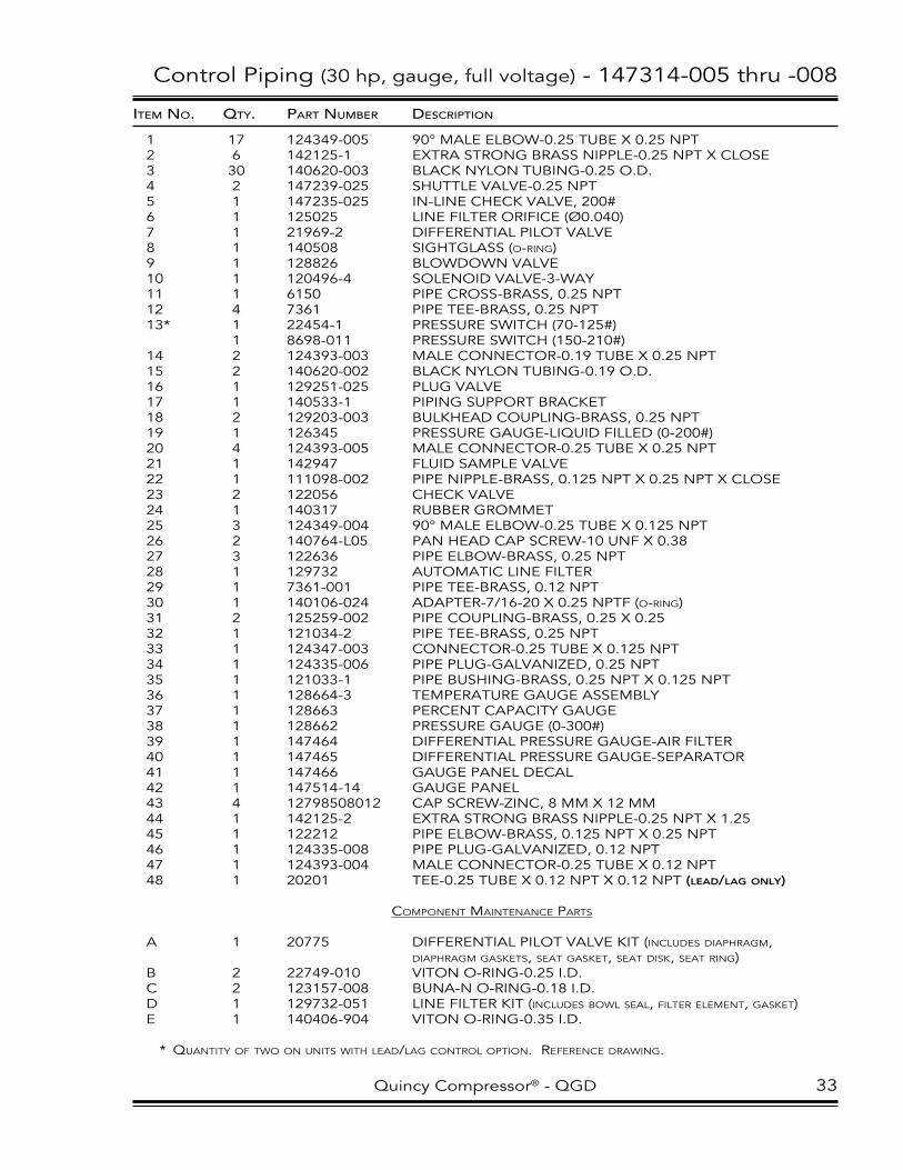
Control Piping (30 hp, gauge, full voltage) - 147314-005 thru -008
itemNo. Qty. PartNumber DescriPtioN
1 17 124349-005 90° MAle elBOw-0.25 TuBe X 0.25 NPT2 6 142125-1 eXTRA STRONG BRASS NIPPle-0.25 NPT X ClOSe3 30 140620-003 BlACK NylON TuBING-0.25 O.D.4 2 147239-025 ShuTTle vAlve-0.25 NPT5 1 147235-025 IN-lINe CheCK vAlve, 200#6 1 125025 lINe FIlTeR ORIFICe (Ø0.040)7 1 21969-2 DIFFeReNTIAl PIlOT vAlve8 1 140508 SIGhTGlASS (o-ring)9 1 128826 BlOwDOwN vAlve10 1 120496-4 SOleNOID vAlve-3-wAy11 1 6150 PIPe CROSS-BRASS, 0.25 NPT12 4 7361 PIPe Tee-BRASS, 0.25 NPT13* 1 22454-1 PReSSuRe SwITCh (70-125#) 1 8698-011 PReSSuRe SwITCh (150-210#)14 2 124393-003 MAle CONNeCTOR-0.19 TuBe X 0.25 NPT15 2 140620-002 BlACK NylON TuBING-0.19 O.D.16 1 129251-025 PluG vAlve17 1 140533-1 PIPING SuPPORT BRACKeT18 2 129203-003 BulKheAD COuPlING-BRASS, 0.25 NPT19 1 126345 PReSSuRe GAuGe-lIQuID FIlleD (0-200#)20 4 124393-005 MAle CONNeCTOR-0.25 TuBe X 0.25 NPT21 1 142947 FluID SAMPle vAlve22 1 111098-002 PIPe NIPPle-BRASS, 0.125 NPT X 0.25 NPT X ClOSe23 2 122056 CheCK vAlve24 1 140317 RuBBeR GROMMeT25 3 124349-004 90° MAle elBOw-0.25 TuBe X 0.125 NPT26 2 140764-l05 PAN heAD CAP SCRew-10 uNF X 0.3827 3 122636 PIPe elBOw-BRASS, 0.25 NPT28 1 129732 AuTOMATIC lINe FIlTeR29 1 7361-001 PIPe Tee-BRASS, 0.12 NPT30 1 140106-024 ADAPTeR-7/16-20 X 0.25 NPTF (o-ring)31 2 125259-002 PIPe COuPlING-BRASS, 0.25 X 0.2532 1 121034-2 PIPe Tee-BRASS, 0.25 NPT33 1 124347-003 CONNeCTOR-0.25 TuBe X 0.125 NPT34 1 124335-006 PIPe PluG-GAlvANIzeD, 0.25 NPT35 1 121033-1 PIPe BuShING-BRASS, 0.25 NPT X 0.125 NPT36 1 128664-3 TeMPeRATuRe GAuGe ASSeMBly37 1 128663 PeRCeNT CAPACITy GAuGe38 1 128662 PReSSuRe GAuGe (0-300#)39 1 147464 DIFFeReNTIAl PReSSuRe GAuGe-AIR FIlTeR40 1 147465 DIFFeReNTIAl PReSSuRe GAuGe-SePARATOR41 1 147466 GAuGe PANel DeCAl42 1 147514-14 GAuGe PANel43 4 12798508012 CAP SCRew-zINC, 8 MM X 12 MM44 1 142125-2 eXTRA STRONG BRASS NIPPle-0.25 NPT X 1.2545 1 122212 PIPe elBOw-BRASS, 0.125 NPT X 0.25 NPT46 1 124335-008 PIPe PluG-GAlvANIzeD, 0.12 NPT47 1 124393-004 MAle CONNeCTOR-0.25 TuBe X 0.12 NPT48 1 20201 Tee-0.25 TuBe X 0.12 NPT X 0.12 NPT (leaD/lag only)
coMponent Maintenance partS
A 1 20775 DIFFeReNTIAl PIlOT vAlve KIT (includeS diaphragM, diaphragM gaSketS, Seat gaSket, Seat diSk, Seat ring)B 2 22749-010 vITON O-RING-0.25 I.D.C 2 123157-008 BuNA-N O-RING-0.18 I.D.D 1 129732-051 lINe FIlTeR KIT (includeS Bowl Seal, filter eleMent, gaSket)e 1 140406-904 vITON O-RING-0.35 I.D.
* quantity of two on unitS with lead/lag control option. reference drawing.
Quincy Compressor® - QGD 33

Control Piping (30 hp, gauge, wye-delta) - 147314-009 thru -012
LEAD/LAG DETAIL
SEE DETAILFOR LEAD/LAG
P
I
O
SAMPLEPORT
1
1
1
1
1
1
1
1
1
1
1
1
22
2
22
3
3
3
3
3
3
3
3
4
4
5
6
A 7
9
10
11 12
12
12
14
17
26
18
19
20
20
20
20
21
23 C
30
30
27
45 E
31 2
32
33
33
33
34
13
36
37
38
39
40
35
3535
47
SEEAIRENDGROUP
43 42 41
3
3
3
3
3
3
1
LOWERPORT
UPPERPORT
8
B
16
44
2746
14
15
18
1
3
28
C
16
1
25
2230
30
C 23
2
24
30
30
3
29
1
3
3
320
34 Quincy Compressor® - QGD

Control Piping (30 hp, gauge, wye-delta) - 147314-009 thru -012
itemNo. Qty. PartNumber DescriPtioN
1 16 124349-005 90° MAle elBOw-0.25 TuBe X 0.25 NPT2 7 142125-1 eXTRA STRONG BRASS NIPPle-0.25 NPT X ClOSe3 30 140620-003 BlACK NylON TuBING-0.25 O.D.4 2 147239-025 ShuTTle vAlve-0.25 NPT5 1 147235-025 IN-lINe CheCK vAlve, 200#6 1 125025 lINe FIlTeR ORIFICe (Ø0.040)7 1 21969-2 DIFFeReNTIAl PIlOT vAlve8 1 140508 SIGhTGlASS (o-ring)9 1 128826 BlOwDOwN vAlve10 1 120496-4 SOleNOID vAlve-3-wAy11 1 6150 PIPe CROSS-BRASS, 0.25 NPT12 3 7361 PIPe Tee-BRASS, 0.25 NPT13 1 121033-1 PIPe BuShING-BRASS, 0.25 NPT X 0.125 NPT14 2 124393-003 MAle CONNeCTOR-0.19 TuBe X 0.25 NPT15 2 140620-002 BlACK NylON TuBING-0.19 O.D.16 2 142125-18 eXTRA STRONG BRASS NIPPle-0.25 NPT X 2.0017 1 140533-1 PIPING SuPPORT BRACKeT18 2 129203-003 BulKheAD COuPlING-BRASS, 0.25 NPT19 1 126345 PReSSuRe GAuGe-lIQuID FIlleD (0-200#)20 5 124393-005 MAle CONNeCTOR-0.25 TuBe X 0.25 NPT21 1 142947 FluID SAMPle vAlve22 1 122212 PIPe elBOw-BRASS, 0.125 NPT X 0.25 NPT23 2 122056 CheCK vAlve24 1 140317 RuBBeR GROMMeT25 1 124393-004 MAle CONNeCTOR-0.25 TuBe X 0.12 NPT26 2 140764-l05 PAN heAD CAP SCRew-10 uNF X 0.3827 2 122636 PIPe elBOw-BRASS, 0.25 NPT28 1 129732 AuTOMATIC lINe FIlTeR29 1 124335-008 PIPe PluG-GAlvANIzeD, 0.12 NPT30 5 124349-004 90° MAle elBOw-0.25 TuBe X 0.125 NPT31 1 125259-002 PIPe COuPlING-BRASS, 0.25 X 0.2532 1 121034-2 PIPe Tee-BRASS, 0.25 NPT33 3 124347-003 CONNeCTOR-0.25 TuBe X 0.125 NPT34 1 124335-006 PIPe PluG-GAlvANIzeD, 0.25 NPT35 1 22454-1 PReSSuRe SwITCh (70-125#) 1 8698-011 PReSSuRe SwITCh (150-210#)36 1 128664-3 TeMPeRATuRe GAuGe ASSeMBly37 1 128663 PeRCeNT CAPACITy GAuGe38 1 128662 PReSSuRe GAuGe (0-300#)39 1 147464 DIFFeReNTIAl PReSSuRe GAuGe-AIR FIlTeR40 1 147465 DIFFeReNTIAl PReSSuRe GAuGe-SePARATOR41 1 147466 GAuGe PANel DeCAl42 1 147514-14 GAuGe PANel43 4 12798508012 CAP SCRew-zINC, 8 MM X 12 MM44 1 121033-2 PIPe BuShING-BRASS, 0.38 NPT X 0.25 NPT45 1 140106-024 ADAPTeR-7/16-20 X 0.25 NPTF (o-ring)46 1 129251-025 PluG vAlve47 1 20201 Tee-0.25 TuBe X 0.12 NPT X 0.12 NPT (leaD/lag only)
coMponent Maintenance partS
A 1 20775 DIFFeReNTIAl PIlOT vAlve KIT (includeS diaphragM, diaphragM gaSketS, Seat gaSket, Seat diSk, Seat ring)B 2 22749-010 vITON O-RING-0.25 I.D.C 2 123157-008 BuNA-N O-RING-0.18 I.D.D 1 129732-051 lINe FIlTeR KIT (includeS Bowl Seal, filter eleMent, gaSket)e 1 140406-904 vITON O-RING-0.35 I.D.
* quantity of two on unitS with lead/lag control option. reference drawing.
Quincy Compressor® - QGD 35

Control Piping (30 hp, microprocessor, full voltage) - 147315-002
PI
O
SEE AIREND GROUP
3
2
1
SAMPLEPORT
PRESSURESENSOR
1
1
1
1
1
1
1
1
1
1
1
2
2
2
2
3
3
33
3
4
4
5
6
A 7
B 8
9
10
12
1212
13
14
14
15
16
17 26
18
18
19
20
20
20
21
22
23 C
2431
32
25
27
27
27
1
28 D
29
27
30
E 33
34
2
3
35
3
LOWER PORT
UPPER PORT
LOWER PORT
UPPER PORT
3
3
NOTES-UNLESS OTHERWISE SPECIFIED: 1) ITEM 11 (CABLE ASSEMBLY) IS NOT SHOWN. 2) ITEM 36 LOCATED ON BACK SIDE OF RESERVOIR.
(NOTE 2)
36 F
36 Quincy Compressor® - QGD

Control Piping (30 hp, microprocessor, full voltage) - 147315-002
itemNo. Qty. PartNumber DescriPtioN
1 12 124349-005 90° MAle elBOw-0.25 TuBe X 0.25 NPT2 5 142125-1 eXTRA STRONG BRASS NIPPle-0.25 NPT X ClOSe3 20 140620-003 BlACK NylON TuBING-0.25 O.D.4 2 147239-025 ShuTTle vAlve-0.25 NPT5 1 147235-025 IN-lINe CheCK vAlve, 200#6 1 125025 lINe FIlTeR ORIFICe (Ø0.040)7 1 21969-2 DIFFeReNTIAl PIlOT vAlve8 1 140508 SIGhTGlASS (o-ring)9 1 128826 BlOwDOwN vAlve10 1 120496-12 SOleNOID vAlve-3-wAy11 1 146296 CABle ASSeMBly-5 MeTeR12 3 7361 PIPe Tee-BRASS, 0.25 NPT13 1 121033-1 PIPe BuShING-BRASS, 0.25 NPT X 0.125 NPT14 2 124393-003 MAle CONNeCTOR-0.19 TuBe X 0.25 NPT15 2 140620-002 BlACK NylON TuBING-0.19 O.D.16 1 142125-18 eXTRA STRONG BRASS NIPPle-0.25 NPT X 2.0017 1 140533-1 PIPING SuPPORT BRACKeT18 2 129203-003 BulKheAD COuPlING-BRASS, 0.25 NPT19 1 126345 PReSSuRe GAuGe-lIQuID FIlleD (0-200#)20 3 124393-005 MAle CONNeCTOR-0.25 TuBe X 0.25 NPT21 1 142947 FluID SAMPle vAlve22 1 122212 PIPe elBOw-BRASS, 0.125 NPT X 0.25 NPT23 1 122056 CheCK vAlve24 1 140317 RuBBeR GROMMeT25 1 124349-004 90° MAle elBOw-0.25 TuBe X 0.125 NPT26 2 140764-l05 PAN heAD CAP SCRew-10 uNF X 0.3827 4 122636 PIPe elBOw-BRASS, 0.25 NPT28 1 129732 AuTOMATIC lINe FIlTeR29 1 124335-006 PIPe PluG-GAlvANIzeD, 0.25 NPT30 1 142125-2 eXTRA STRONG BRASS NIPPle-0.25 NPT X 1.2531 1 111098-002 PIPe NIPPle-BRASS, 0.125 NPT X 0.25 NPT X ClOSe32 1 125259-002 PIPe COuPlING-BRASS, 0.25 X 0.2533 1 140106-024 ADAPTeR-7/16-20 X 0.25 NPTF (o-ring)34 1 129251-025 PluG vAlve35 1 124335-008 PIPe PluG-GAlvANIzeD, 0.12 NPT36 1 128883-075 PIPe PluG-3/4-16 (o-ring)
coMponent Maintenance partS
A 1 20775 DIFFeReNTIAl PIlOT vAlve KIT (includeS diaphragM, diaphragM gaSketS, Seat gaSket, Seat diSk, Seat ring)B 2 22749-010 vITON O-RING-0.25 I.D.C 2 123157-008 BuNA-N O-RING-0.18 I.D.D 1 129732-051 lINe FIlTeR KIT (includeS Bowl Seal, filter eleMent, gaSket)e 1 140406-904 vITON O-RING-0.35 I.D.F 1 140406-908 vITON O-RING-0.64 I.D.
Quincy Compressor® - QGD 37
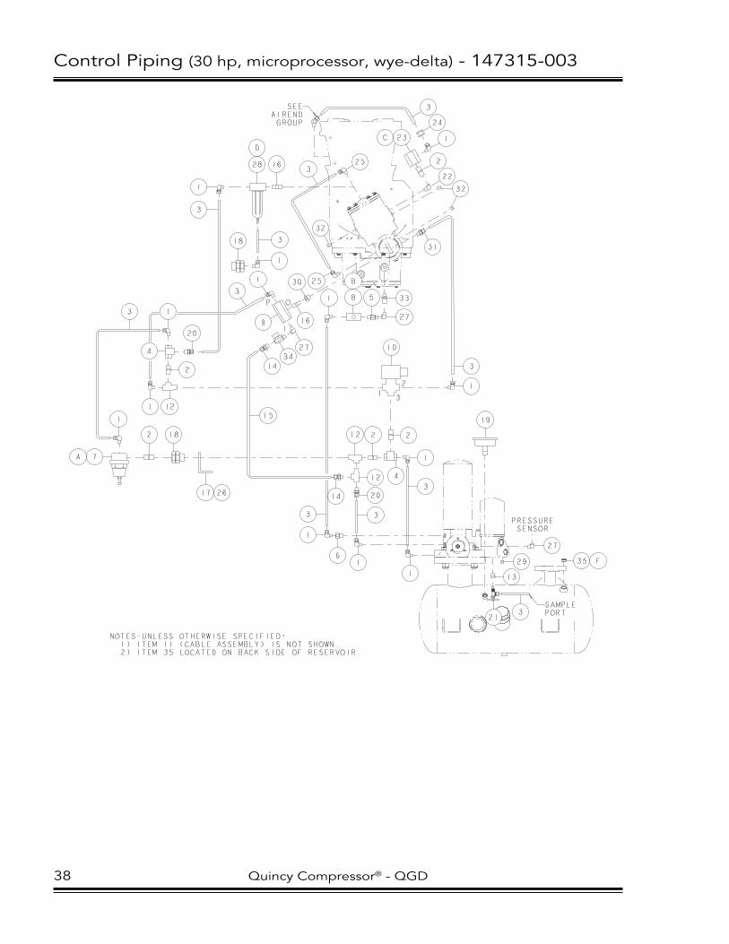
Control Piping (30 hp, microprocessor, wye-delta) - 147315-003
NOTES-UNLESS OTHERWISE SPECIFIED: 1) ITEM 11 (CABLE ASSEMBLY) IS NOT SHOWN. 2) ITEM 35 LOCATED ON BACK SIDE OF RESERVOIR.
SAMPLEPORT
PRESSURESENSOR
3
2
1
P
I
O
1
1
1
1
1
1
1
1
1
1
1
1
2
2 22
2
3
3
3
3
3
1
3
3
3
3
3
3
4
4
5
6
A 7
8
B
9
10
12
12
12
13
14
14
15
16
16
17 26
18
18
19
20
21
22
C 23
24
25
25
27
27
27
28
D
29
30
31
33
34
32
20
32
SEEAIRENDGROUP
35 F
38 Quincy Compressor® - QGD
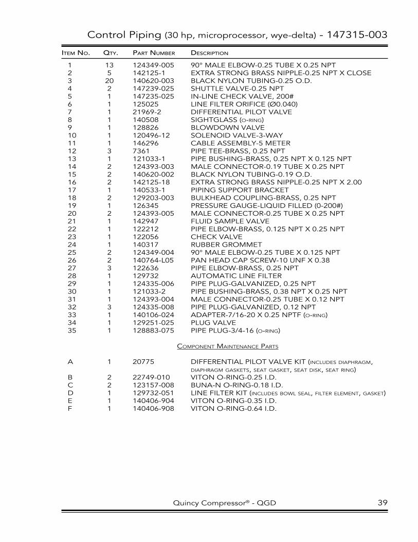
Control Piping (30 hp, microprocessor, wye-delta) - 147315-003
itemNo. Qty. PartNumber DescriPtioN
1 13 124349-005 90° MAle elBOw-0.25 TuBe X 0.25 NPT2 5 142125-1 eXTRA STRONG BRASS NIPPle-0.25 NPT X ClOSe3 20 140620-003 BlACK NylON TuBING-0.25 O.D.4 2 147239-025 ShuTTle vAlve-0.25 NPT5 1 147235-025 IN-lINe CheCK vAlve, 200#6 1 125025 lINe FIlTeR ORIFICe (Ø0.040)7 1 21969-2 DIFFeReNTIAl PIlOT vAlve8 1 140508 SIGhTGlASS (o-ring)9 1 128826 BlOwDOwN vAlve10 1 120496-12 SOleNOID vAlve-3-wAy11 1 146296 CABle ASSeMBly-5 MeTeR12 3 7361 PIPe Tee-BRASS, 0.25 NPT13 1 121033-1 PIPe BuShING-BRASS, 0.25 NPT X 0.125 NPT14 2 124393-003 MAle CONNeCTOR-0.19 TuBe X 0.25 NPT15 2 140620-002 BlACK NylON TuBING-0.19 O.D.16 2 142125-18 eXTRA STRONG BRASS NIPPle-0.25 NPT X 2.0017 1 140533-1 PIPING SuPPORT BRACKeT18 2 129203-003 BulKheAD COuPlING-BRASS, 0.25 NPT19 1 126345 PReSSuRe GAuGe-lIQuID FIlleD (0-200#)20 2 124393-005 MAle CONNeCTOR-0.25 TuBe X 0.25 NPT21 1 142947 FluID SAMPle vAlve22 1 122212 PIPe elBOw-BRASS, 0.125 NPT X 0.25 NPT23 1 122056 CheCK vAlve24 1 140317 RuBBeR GROMMeT25 2 124349-004 90° MAle elBOw-0.25 TuBe X 0.125 NPT26 2 140764-l05 PAN heAD CAP SCRew-10 uNF X 0.3827 3 122636 PIPe elBOw-BRASS, 0.25 NPT28 1 129732 AuTOMATIC lINe FIlTeR29 1 124335-006 PIPe PluG-GAlvANIzeD, 0.25 NPT30 1 121033-2 PIPe BuShING-BRASS, 0.38 NPT X 0.25 NPT31 1 124393-004 MAle CONNeCTOR-0.25 TuBe X 0.12 NPT32 3 124335-008 PIPe PluG-GAlvANIzeD, 0.12 NPT33 1 140106-024 ADAPTeR-7/16-20 X 0.25 NPTF (o-ring)34 1 129251-025 PluG vAlve35 1 128883-075 PIPe PluG-3/4-16 (o-ring)
coMponent Maintenance partS
A 1 20775 DIFFeReNTIAl PIlOT vAlve KIT (includeS diaphragM, diaphragM gaSketS, Seat gaSket, Seat diSk, Seat ring)B 2 22749-010 vITON O-RING-0.25 I.D.C 2 123157-008 BuNA-N O-RING-0.18 I.D.D 1 129732-051 lINe FIlTeR KIT (includeS Bowl Seal, filter eleMent, gaSket)e 1 140406-904 vITON O-RING-0.35 I.D.F 1 140406-908 vITON O-RING-0.64 I.D.
Quincy Compressor® - QGD 39

Control Piping (40/50 hp, gauge) - 147314-013 thru -016
LEAD/LAG DETAIL
SEE DETAILFOR LEAD/LAG
P
I
O
SAMPLEPORT
1
1
1
1
1
1
1
1
1
1
1
1
1
1
2
2
2
22
2
3
3
3
3
3
3
34
4
4
5
A 7
9
10
11
12
12
12
14
16
18
19
20
44
20
20
21
23 C
24
30
30
25
22
28 E
31 2
32
33
33
33
36
37
38
39
40
35
3535
46
50
25
SEEAIRENDGROUP
43 42 41
15
3
3
3
3
3
8
B
3
25
25
47
3
16 13
18
1 3
3
23
C
29
45 F
648FLUID FILTER BLOCK
27 D
3
49
17 26
40 Quincy Compressor® - QGD

Control Piping (40/50 hp, gauge) - 147314-013 thru -016
ITEM NO. QTY. PART NUMBER DESCRIPTION
1 13 124349-005 90° MALE ELBOW-0.25 TUBE X 0.25 NPT2 7 142125-1 EXTRA STRONG BRASS NIPPLE-0.25 NPT X CLOSE3 44 140620-003 BLACK NYLON TUBING-0.25 O.D.4 2 147239-025 SHUTTLE VALVE-0.25 NPT5 1 147235-025 IN-LINE CHECK VALVE, 200#6 1 125025-007 LINE FILTER ORIFICE (Ø0.060)7 1 21969-2 DIFFERENTIAL PILOT VALVE8 1 140508 SIGHTGLASS (O-RING)9 1 128826 BLOWDOWN VALVE10 1 120496-4 SOLENOID VALVE-3-WAY11 1 6150 PIPE CROSS-BRASS, 0.25 NPT12 3 7361 PIPE TEE-BRASS, 0.25 NPT13 1 121033-2 PIPE BUSHING-BRASS, 0.38 NPT X 0.25 NPT14 1 124393-012 MALE CONNECTOR-0.38 TUBE X 0.25 NPT15 2 140620-004 BLACK NYLON TUBING-0.38 O.D.16 2 142125-18 EXTRA STRONG BRASS NIPPLE-0.25 NPT X 2.0017 1 140533-1 PIPING SUPPORT BRACKET18 2 129203-003 BULKHEAD COUPLING-BRASS, 0.25 NPT19 1 126345 PRESSURE GAUGE-LIQUID FILLED (0-200#)20 3 124393-005 MALE CONNECTOR-0.25 TUBE X 0.25 NPT21 1 142947 FLUID SAMPLE VALVE22 1 122212 PIPE ELBOW-BRASS, 0.125 NPT X 0.25 NPT23 2 122056 CHECK VALVE24 1 140317 RUBBER GROMMET25 1 124393-004 MALE CONNECTOR-0.25 TUBE X 0.12 NPT26 2 140764-L05 PAN HEAD CAP SCREW-10 UNF X 0.3827 1 128886-006 ELBOW-0.50 TUBE X 3/4-16 (O-RING)28 1 129732 AUTOMATIC LINE FILTER29 2 124335-008 PIPE PLUG-GALVANIZED, 0.12 NPT30 6 124349-004 90° MALE ELBOW-0.25 TUBE X 0.125 NPT31 1 125259-002 PIPE COUPLING-BRASS, 0.25 X 0.2532 1 121034-2 PIPE TEE-BRASS, 0.25 NPT33 3 124347-003 CONNECTOR-0.25 TUBE X 0.125 NPT34 2 140620-005 BLACK NYLON TUBING-0.50 O.D.35* 1 22454-1 PRESSURE SWITCH (70-125#) 1 8698-011 PRESSURE SWITCH (150-210#)36 1 128664-3 TEMPERATURE GAUGE ASSEMBLY37 1 128663 PERCENT CAPACITY GAUGE38 1 128662 PRESSURE GAUGE (0-300#)39 1 147464 DIFFERENTIAL PRESSURE GAUGE-AIR FILTER40 1 147465 DIFFERENTIAL PRESSURE GAUGE-SEPARATOR41 1 147466 GAUGE PANEL DECAL42 1 147514-14 GAUGE PANEL43 4 12798508012 CAP SCREW-ZINC, 8 MM X 12 MM44 1 124393-015 MALE CONNECTOR-0.50 TUBE X 0.25 NPT45 1 128886-003 ELBOW-0.25 TUBE X 7/16-20 (O-RING)46 1 129251-025 PLUG VALVE47 1 124349-009 90° MALE ELBOW-0.38 TUBE X 0.125 NPT48 1 142125-3 EXTRA STRONG BRASS NIPPLE-0.25 NPT X 1.5049 1 125780-003 90° FEMALE ELBOW-0.25 TUBE X 0.25 NPT50 1 20201 TEE-0.25 TUBE X 0.12 NPT X 0.12 NPT (LEAD/LAG ONLY)
COMPONENT MAINTENANCE PARTS
A 1 20775 DIFFERENTIAL PILOT VALVE KIT (INCLUDES DIAPHRAGM, DIAPHRAGM GASKETS, SEAT GASKET, SEAT DISK, SEAT RING)B 2 22749-010 VITON O-RING-0.25 I.D.C 2 123157-008 BUNA-N O-RING-0.18 I.D.D 2 140406-908 VITON O-RING-0.64 I.D.E 1 129732-051 LINE FILTER KIT (INCLUDES BOWL SEAL, FILTER ELEMENT, GASKET)F 1 140406-904 VITON O-RING-0.35 I.D.
* QUANTITY OF TWO ON UNITS WITH LEAD/LAG CONTROL OPTION. REFERENCE DRAWING.
Quincy Compressor® - QGD 41

Control Piping (40/50 hp, microprocessor) - 147315-004
NOTES-UNLESS OTHERWISE SPECIFIED: 1) ITEM 35 LOCATED ON BACK SIDE OF RESERVOIR.
P
I
O
SAMPLEPORT
31
1
1
1
1
1
1
1
1
2
2
22
2
3
3
35
4
4
5
A 7
9
10
12
12
14
16
18 19
33
20
21
24
22
28 D
13
25
SEEAIRENDGROUP
15
3
8
B
3
31
31
37
3
16 13
18
1 3
3
23
C
29
30 E
636FLUIDFILTERBLOCK
F 34
3
32
17 26
PRESSURESENSOR
27
29
29
3
12
38 F
42 Quincy Compressor® - QGD

Control Piping (40/50 hp, microprocessor) - 147315-004
itemNo. Qty. PartNumber DescriPtioN
1 9 124349-005 90° MAle elBOw-0.25 TuBe X 0.25 NPT2 5 142125-1 eXTRA STRONG BRASS NIPPle-0.25 NPT X ClOSe3 20 140620-003 BlACK NylON TuBING-0.25 O.D.4 2 147239-025 ShuTTle vAlve-0.25 NPT5 1 147235-025 IN-lINe CheCK vAlve, 200#6 1 125025-007 lINe FIlTeR ORIFICe (Ø0.060)7 1 21969-2 DIFFeReNTIAl PIlOT vAlve8 1 140508 SIGhTGlASS (o-ring)9 1 128826 BlOwDOwN vAlve10 1 120496-12 SOleNOID vAlve-3-wAy11 1 121033-2 PIPe BuShING-BRASS, 0.38 NPT X 0.25 NPT12 3 7361 PIPe Tee-BRASS, 0.25 NPT13 1 129251-025 PluG vAlve14 1 124393-012 MAle CONNeCTOR-0.38 TuBe X 0.25 NPT15 2 140620-004 BlACK NylON TuBING-0.38 O.D.16 2 142125-18 eXTRA STRONG BRASS NIPPle-0.25 NPT X 2.0017 1 140533-1 PIPING SuPPORT BRACKeT18 2 129203-003 BulKheAD COuPlING-BRASS, 0.25 NPT19 1 126345 PReSSuRe GAuGe-lIQuID FIlleD (0-200#)20 1 124393-005 MAle CONNeCTOR-0.25 TuBe X 0.25 NPT21 1 142947 FluID SAMPle vAlve22 1 122212 PIPe elBOw-BRASS, 0.125 NPT X 0.25 NPT23 1 122056 CheCK vAlve24 1 140317 RuBBeR GROMMeT25 1 124393-004 MAle CONNeCTOR-0.25 TuBe X 0.12 NPT26 2 140764-l05 PAN heAD CAP SCRew-10 uNF X 0.3827 1 122636 PIPe elBOw-BRASS, 0.25 NPT28 1 129732 AuTOMATIC lINe FIlTeR29 4 124335-008 PIPe PluG-GAlvANIzeD, 0.12 NPT30 1 128886-003 elBOw-0.25 TuBe X 7/16-20 (o-ring)31 3 124349-004 90° MAle elBOw-0.25 TuBe X 0.125 NPT32 1 125780-003 90° FeMAle elBOw-0.25 TuBe X 0.25 NPT33 1 124393-015 MAle CONNeCTOR-0.50 TuBe X 0.25 NPT34 1 128886-006 elBOw-0.50 TuBe X 3/4-16 (o-ring)35 2 140620-005 BlACK NylON TuBING-0.50 O.D.36 1 142125-3 eXTRA STRONG BRASS NIPPle-0.25 NPT X 1.5037 1 124349-010 90° MAle elBOw-0.38 TuBe X 0.25 NPT38 1 128883-075 PIPe PluG-3/4-16 (o-ring)
coMponent Maintenance partS
A 1 20775 DIFFeReNTIAl PIlOT vAlve KIT (includeS diaphragM, diaphragM gaSketS, Seat gaSket, Seat diSk, Seat ring)B 2 22749-010 vITON O-RING-0.25 I.D.C 2 123157-008 BuNA-N O-RING-0.18 I.D.D 1 129732-051 lINe FIlTeR KIT (includeS Bowl Seal, filter eleMent, gaSket)e 1 140406-904 vITON O-RING-0.35 I.D.F 3 140406-908 vITON O-RING-0.64 I.D.
Quincy Compressor® - QGD 43

Air Piping (20/25/30 hp) - 146922-001/-002
1
2
3 A B
B A 3
4 C D
5 D
6 E
7
7
8
9
9
10
11
12
13
14
15
15
14
13
1617
18
19
20
TO LINE FILTER
44 Quincy Compressor® - QGD

Air Piping (20/25/30 hp) - 146922-001/-002
ITEM NO. QTY. PART NUMBER DESCRIPTION
1 1 146971-05 FORMED TUBE ASSEMBLY-PAR-FLANGED, 1.00 O.D.2 1 147528 HOSE ASSEMBLY-0.875 X 21.50 LONG3 2 140676-020 ELBOW-1.00 TUBE X 1-5/8-12 (O-RING)4 1 140682-023 CONNECTOR-1.00 TUBE X 1-5/8-12 (O-RING)5 1 140677-014 ELBOW-1.00 TUBE X 1.00-11.5 NPTF (O-RING)6 1 147573-3275 MOISTURE SEPARATOR7* 1 146395 MANUAL CONDENSATE DRAIN 1 115698-125 ELECTRONIC DRAIN VALVE (OPTIONAL)
8 1 126020-010 PIPE NIPPLE-GALVANIZED, 1.00 NPT X 2.009 2 21740 PIPE COUPLING-GALVANIZED, 1.00 NPT10 4 142578-J21 CAP SCREW-ZINC, 1/4-20 UNC X 3.00, GRADE 5 (@ 6 FT-LBS)11 4 112272-J02 SELF-LOCKING HEX NUT-ZINC, 1/4-20 UNC12 1 126020-034 PIPE NIPPLE-GALVANIZED, 1.00 NPT X 5.0013 1 121033-5 PIPE BUSHING-BRASS, 0.50 NPT X 0.25 NPT14 1 124349-005 90° MALE ELBOW-0.25 TUBE X 0.25 NPT15 2 140620-003 BLACK NYLON TUBING-0.25 O.D.16 2 124393-005 MALE CONNECTOR-0.25 TUBE X 0.25 NPT17 2 129203-003 BULKHEAD COUPLING-BRASS, 0.25 NPT18 4 141822-334 TUBE CLAMP-1.31 I.D.19 2 141827-05 TUBE CLAMP COVER PLATE-1.38 I.D.20** 1 142125-1 EXTRA STRONG BRASS NIPPLE-0.25 NPT X CLOSE
COMPONENT MAINTENANCE PARTS
A 2 140406-916 VITON O-RING-1.17 I.D.B 2 140675-007 VITON O-RING/FACE SEAL-1.18 I.D.C 1 140406-920 VITON O-RING-1.48 I.D.D 2 140675-006 VITON O-RING/FACE SEAL-0.93 I.D.E 1 145999-050 VITON O-RING
* ELECTRONIC DRAIN VALVE IS OPTIONAL. ** ITEM 20 (NIPPLE) USED ONLY WITH ELECTRONIC DRAIN VALVE. @ INDICATES TORQUE VALUE IN FOOT POUNDS (LUBRICATED THREADS).
Quincy Compressor® - QGD 45
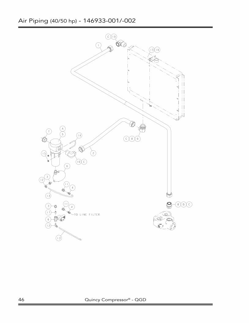
Air Piping (40/50 hp) - 146933-001/-002
1
2
3
3
6
7
8 B C
C B 9
C 10
10 C
5
A
17
13
13
6
TO LINE FILTER
12
11
4
12
114
14
15
15 16
46 Quincy Compressor® - QGD

Air Piping (40/50 hp) - 146933-001/-002
itemNo. Qty. PartNumber DescriPtioN
1 1 146893-09 FORMeD TuBe ASSeMBly-PAR-FlANGeD, 1.50 O.D.2 1 146893-10 FORMeD TuBe ASSeMBly-PAR-FlANGeD, 1.50 O.D.3 1 121033-5 PIPe BuShING-BRASS, 0.50 NPT X 0.25 NPT4 2 124393-012 MAle CONNeCTOR-0.38 TuBe X 0.25 NPT5 1 147573-3550 MOISTuRe SePARATOR6 1 146395 MANuAl CONDeNSATe DRAIN 1 115698-125* eleCTRONIC DRAIN vAlve (optional)7 1 125868-021 PIPe BuShING-GAlvANIzeD, 1.50 NPT X 1.25 NPT8 1 140682-026 CONNeCTOR-1.50 TuBe X 1-7/8-12 (o-ring)9 1 140676-024 elBOw-1.50 TuBe X 1-7/8-12 (o-ring)10 2 140677-017 elBOw-1.50 TuBe X 1-1/2-11.5 NPTF (o-ring)11 2 129203-003 BulKheAD COuPlING-BRASS, 0.25 NPT12 2 124349-010 90° MAle elBOw-0.38 TuBe X 0.25 NPT13 2 140620-004 BlACK NylON TuBING-0.38 O.D.14 1 120806 u-BOlT, 5/16-18 uNC15 6 112272-K02 SelF-lOCKING heX NuT-zINC, 5/16-18 uNC16 4 141631-K10 CAP SCRew-5/16-18 uNC X 0.75, GRADe 5 (@ 23 ft-lBS)17** 1 142125-1 eXTRA STRONG BRASS NIPPle-0.25 NPT X ClOSe
coMponent Maintenance partS
A 1 145999-051 vITON O-RING B 2 140406-924 vITON O-RING-1.72 I.D.C 4 140675-008 vITON O-RING/FACe SeAl-1.49 I.D.
* electronic drain valve iS optional. ** iteM 11 (nipple) uSed only with electronic drain valve. @ indicateS torque value in foot poundS (luBricated threadS).
Quincy Compressor® - QGD 47

Receiver (20/25/30 hp) - 147593-001
6
7
23
4
6
5
15 A
A 14
13
12
11
9
1
8
16
10
48 Quincy Compressor® - QGD

Receiver (20/25/30 hp) - 147593-001
itemNo. Qty. PartNumber DescriPtioN
1 1 147535-200 120 GAllON ReCeIveR2 1 110425-100 QuARTeR TuRN vAlve3 1 126020-014 PIPe NIPPle-GAlvANIzeD, 1.00 NPT X 2.504 1 125868-029 PIPe BuShING-GAlvANIzeD, 2.00 NPT X 1.00 NPT5 1 110514-300 PReSSuRe GAuGe6 2 121033-5 PIPe BuShING-BRASS, 0.50 NPT X 0.25 NPT7 1 2713 DRAINCOCK-0.25 NPT8 1 143556-200 PReSSuRe RelIeF vAlve9 8 141631-N12 CAP SCRew-1/2-13 uNC X 1.00, GRADe 5 (@ 23 ft-lBS)10 8 112272-N02 SelF-lOCKING heX NuT-zINC, 1/2-13 uNC11 2 146002-4 DeCAl-QuINCy lOGO, whITe (17.5 inch)12 1 5042 DeCAl-DRAIN TANK eveRy DAy13 1 146754-04 hOSe ASSeMBly-SeAl-lOK, 45° BeND14 1 140677-014 elBOw-1.00 TuBe X 1.00-11.5 NPTF (o-ring)15 1 140681-015 CONNeCTOR-1.00 NPTF X 1.00 TuBe (o-ring)16 1 124335-004 PIPe PluG-GAlvANIzeD, 3.00 NPT
coMponent Maintenance partS
A 2 140675-006 vITON O-RING/FACe SeAl-0.93 I.D.
@ indicateS torque value in foot poundS (luBricated threadS).
Quincy Compressor® - QGD 49

Fluid Piping (20/25/30 hp) - 146908-001/-002
50 Quincy Compressor® - QGD
Updated August 2010

Fluid Piping (20/25/30 hp) - 146908-001/-002
ITEM NO. QTY. PART NUMBER DESCRIPTION
1 1 128598 FLUID FILTER ELEMENT2 1 146971-01 FORMED TUBE ASSEMBLY-PAR-FLANGED, 0.75 O.D.3 1 146971-02 FORMED TUBE ASSEMBLY-PAR-FLANGED, 0.75 O.D.4 1 146971-03 FORMED TUBE ASSEMBLY-PAR-FLANGED, 0.75 O.D.5 1 146971-04 FORMED TUBE ASSEMBLY-PAR-FLANGED, 0.75 O.D.6 1 146893-13 FORMED TUBE ASSEMBLY-PAR-FLANGED, 0.75 O.D. 1 146893-12* FORMED TUBE ASSEMBLY-PAR-FLANGED, 0.75 O.D.7 1 140682-019 CONNECTOR-0.75 TUBE X 1-5/16-12 (O-RING)8 4 140676-016 ELBOW-0.75 TUBE X 7/8-14 (O-RING)9 1 140682-017 CONNECTOR-0.75 TUBE X 3/4-16 (O-RING)10 1 128786-200 THERMAL VALVE, 200°F11 1 140672-005 TEE-0.75 TUBE X 1-1/16-12 (O-RING)12 1 140676-014 ELBOW-0.75 TUBE X 1-1/16-12 (O-RING) 13 1 140682-016 CONNECTOR-0.75 TUBE X 1-1/16-12 (O-RING)
COMPONENT MAINTENANCE PARTS
A 1 140675-005 VITON O-RING/FACE SEAL-0.74 I.D.B 1 140406-916 VITON O-RING-1.17 I.D.C 1 140675-004 VITON O-RING/FACE SEAL-0.61 I.D.D 1 140406-912 VITON O-RING-0.92 I.D.E 1 140406-908 VITON O-RING-0.64 I.D.
* THIS TUBE ASSEMBLY USED ONLY ON 30 HP, 100 & 125 PSI UNITS.
Quincy Compressor® - QGD 51
Updated August 2010

Fluid Piping (40/50 hp) - 146924-001/-002
1
2
3
4
5
6
7
8
9
10
11
12
13 A B
13
A
B
13
A
B
13
A
B
14 A C
15 A B
15
A
B
AIREND
RESERVOIR
52 Quincy Compressor® - QGD

Fluid Piping (40/50 hp) - 146924-001/-002
itemNo. Qty. PartNumber DescriPtioN
1 1 142136 FluID FIlTeR eleMeNT2 1 146893-04 FORMeD TuBe ASSeMBly-PAR-FlANGeD, 1.00 O.D.3 1 146893-05 FORMeD TuBe ASSeMBly-PAR-FlANGeD, 1.00 O.D.4 1 146893-06 FORMeD TuBe ASSeMBly-PAR-FlANGeD, 1.00 O.D.5 1 146893-08 FORMeD TuBe ASSeMBly-PAR-FlANGeD, 1.00 O.D. (all 40 hp/50 hp, 150#)
1 146893-07 FORMeD TuBe ASSeMBly-PAR-FlANGeD, 1.00 O.D. (50 hp, 100/125#)6 1 146925 FluID MANIFOlD BlOCK7 1 140536-1 TheRMAl vAlve-CARTRIDGe8 1 140537 FluID FIlTeR STuD9 1 146959 FluID MANIFOlD BlOCK SuPPORT10 1 2140 PIPe PluG-0.125 NPT11 2 141631-K10 CAP SCRew-5/16-18 uNC X 0.75, GRADe 5 (@ 23 ft-lBS)12 2 110511-J07 heX heAD SCRew-zINC, 1/4-20 uNC X 0.5013 5 140682-020 CONNeCTOR-1.00 TuBe X 1-5/16-12 (o-ring)14 1 140682-021 CONNeCTOR-1.00 TuBe X 1-1/16-12 (o-ring)15 2 140676-018 elBOw-1.00 TuBe X 1-5/16-12 (o-ring)
coMponent Maintenance partS
A 8 140675-006 vITON O-RING/FACe SeAl-0.93 I.D.B 7 140406-916 vITON O-RING-1.17 I.D.C 1 140406-912 vITON O-RING-0.92 I.D.
Quincy Compressor® - QGD 53

Reservoir (20/25/30 hp) - 146910-001
1
2
3
4
5
6
7
89
10
11 A
12 B
13
14
15
16
17
18
19
20
C
D
21
22
23
24
25
26
54 Quincy Compressor® - QGD

Reservoir (20/25/30 hp) - 146910-001
itemNo. Qty. PartNumber DescriPtioN
1 1 146913-175 AIR/FluID ReSeRvOIR2 3 142201-02 MOTOR MOuNT3 3 12798512050 CAP SCRew-zINC, 12 MM X 50 MM4 6 129303R050 FeNDeR wASheR5 1 122636 PIPe elBOw-BRASS, 0.25 NPT6 1 126016-026 PIPe NIPPle-GAlvANIzeD, 0.25 NPT X 4.007 1 125259-002 PIPe COuPlING-BRASS, 0.25 X 0.258 1 129251-025 PluG vAlve9 1 124335-006 PIPe PluG-GAlvANIzeD, 0.25 NPT10 1 143555-175 PReSSuRe RelIeF vAlve11 1 129844-162 FIlleR CAP (o-ring)12 1 129843-188 SIGhTGlASS (o-ring)13 1 126019-102 PIPe NIPPle-GAlvANIzeD, 0.75 NPT X 13.5014 1 146912 MulTI-PuRPOSe BlOCK15 1 22749-156 vITON O-RING-4.25 I.D.16 1 146914 AIR/FluID SePARATOR eleMeNT17 4 142578-Q20 CAP SCRew-zINC, 5/8-11 uNC X 2.75, GRADe 5 (@ 110 ft-lBS)18 4 124370-Q02 lOCKNuT-5/8-11 uNC19 1 140147-2 TheRMAl vAlve-CARTRIDGe20 1 128599 FluID FIlTeR STuD21 4 123115-08z lOCKwASheR-zINC, 0.5022 4 142578-N16 CAP SCRew-zINC, 1/2-13 uNC X 1.75, GRADe 5 (@ 23 ft-lBS)23 1 22749-226 vITON O-RING-2.00 I.D.24 1 147218-1 PReSSuRe RelIeF vAlve COveR25 1 122560-12 u-BOlT-zINC, 1/2-13 uNC, 0.75 I.D. X 1.2526 2 124370-J02 lOCKNuT-1/4-20 uNC
coMponent Maintenance partS
A 1 140406-920 vITON O-RING-1.48 I.D.B 1 140406-924 vITON O-RING-1.72 I.D.C 1 147563 SePARATOR NIPPleD 1 147564 MINIMuM PReSSuRe CheCK vAlve 1 147564K MINIMuM PReSSuRe CheCK vAlve KIT
@ indicateS torque value in foot poundS (luBricated threadS).
Quincy Compressor® - QGD 55

Reservoir (40/50 hp) - 146923-001/-002
1
2
3
4
4
5
B 6
9
11 C
14
15
16
17
18
13 E
20
21
22
18
18
24
26 25
12
D
7
8
A
10
25
F 19
23
23
(NOTE 1)
NOTES-UNLESS OTHERWISE SPECIFIED: 1) REFERENCE BOM FOR SCREW AND WASHER SIZE. VARIES ACCORDING TO UNIT AIREND.
56 Quincy Compressor® - QGD

Reservoir (40/50 hp) - 146923-001/-002
itemNo. Qty. PartNumber DescriPtioN
1 1 146963-175 AIR/FluID ReSeRvOIR2 4 142201-02 MOTOR MOuNT3 4 12798512050 CAP SCRew-zINC, 12 MM X 50 MM4 8 129303R050 FeNDeR wASheR5 1 143556-175 PReSSuRe RelIeF vAlve6 1 146932 MulTI-PuRPOSe BlOCK7 1 22749-156 vITON O-RING-4.25 I.D.8 1 22749-231 vITON O-RING-2.61 I.D.9 2 146914 AIR/FluID SePARATOR eleMeNT10 4 142578-Q16 CAP SCRew-zINC, 5/8-11 uNC X 1.75, GRADe 5 (@ 110 ft-lBS)11 1 129843-188 SIGhTGlASS (o-ring)12 1 129844-162 FIlleR CAP (o-ring)13 1 128883-075 PIPe PluG-3/4-16 (o-ring)14 1 122636 PIPe elBOw-BRASS, 0.25 NPT15 1 126016-026 PIPe NIPPle-GAlvANIzeD, 0.25 NPT X 4.0016 1 125259-002 PIPe COuPlING-BRASS, 0.25 X 0.2517 1 129251-025 PluG vAlve18 3 124335-006 PIPe PluG-GAlvANIzeD, 0.25 NPT19 1 128883-050 PIPe PluG-1/2-20 (o-ring)20 1 147218 PReSSuRe RelIeF vAlve COveR21 1 122560-08 u-BOlT-zINC, 5/16-18 uNC, 1.50 I.D. X 2.1922 2 112272-K02 SelF-lOCKING heX NuT-zINC, 5/16-18 uNC23 2 2721 PIPe PluG-0.50 NPT24 4 142578-N15 CAP SCRew-zINC, 1/2-13 uNC X 1.50, GRADe 5 (@ 23 ft-lBS) (all 40 hp/50 hp, 150#) 4 142578-q17 CAP SCRew-zINC, 5/8-11 uNC X 2.00, GRADe 5 (@ 110 ft-lBS) (50 hp, 100/125#)25 * 123115-10z lOCKwASheR-zINC, 0.6326** 4 123115-08z lOCKwASheR-zINC, 0.50
coMponent Maintenance partS
A 1 147563 SePARATOR NIPPleB 1 147565K MINIMuM PReSSuRe CheCK vAlve KITC 1 140406-924 vITON O-RING-1.72 I.D.D 1 140406-920 vITON O-RING-1.48 I.D.e 2 140406-908 vITON O-RING-0.64 I.D.F 1 140406-905 vITON O-RING-0.41 I.D.
@ indicateS torque value in foot poundS (luBricated threadS). * quantity of 8 on 50 hp, 100/125#. quantity of 4 on all 40 hp & on 50 hp, 150#. ** iteM 26 not uSed on 50 hp, 100/125#. (reference drawing noteS.)
Quincy Compressor® - QGD 57

Cooler (20/25/30 hp) - 146901-002/-003
12
3
5
6
6
7
8
15
NOTES-UNLESS OTHERWISE SPECIFIED: 1) ITEM 10 (RUBBER SEAL) IS NOT SHOWN AND IS USED AROUND COOLER (AT ATTACHMENT TO SHROUD).
LESS CABINET
WITH CABINET
11
11
11
12
13
14
9
17 16
12
4
58 Quincy Compressor® - QGD

Cooler (20/25/30 hp) - 146901-002/-003
itemNo. Qty. PartNumber DescriPtioN
1 1 146917 COMBINATION COOleR 2 1 146447-01 FAN CONe3 1 147260-10 FAN wheel-18”4 1 147505 COOleR SuPPORT5 1 147506-01 COOleR BRACe6 1 147508-01 ACCeSS PANel COveR (less cabinet) 1 147508-02 ACCeSS PANel COveR (With cabinet)7 1 147059 FAN hOuSING COveR PlATe8 1 147510 COOleR ShROuD9 4 141631-l12 CAP SCRew-3/8-16 uNC X 1.00, GRADe 5 (@ 23 ft-lBS)10 4 141528 RuBBeR SeAl11 14 141631-K10 CAP SCRew-5/16-18 uNC X 0.75, GRADe 5 (@ 23 ft-lBS)12 10 110511-J07 heX heAD SCRew-zINC, 1/4-20 uNC X 0.5013 8 129303l025 FeNDeR wASheR14 2 14654408020 lOCK SCRew-zINC, 8 MM X 20 MM15* 1 147509 FAN GuARD16* 6 122151 heX heAD SCRew-1/4-20 uNC X 0.63, GRADe 5 (@ 6 ft-lBS)17* 6 22456z SPeeD NuT-GRIP, zINC, 1/4-20 uNC
@ indicateS torque value in foot poundS (luBricated threadS). * theSe iteMS not uSed on unitS with caBinet.
Quincy Compressor® - QGD 59

Cooler (40/50 hp) - 146926-001/-003
2
4
5
8
15
1
3
6
7
17
10
9
60 Quincy Compressor® - QGD

Cooler (40/50 hp) - 146926-001/-003
itemNo. Qty. PartNumber DescriPtioN
1 1 147530 COOleR ShROuD2 1 146927-01 COOleR SuPPORT3 1 147533-01 FAN MOTOR PANel4 1 146447-01 FAN CONe5 1 147260-01 FAN wheel-18”6 1 147529-01 ACCeSS PANel-COOleR ShROuD (less cabinet) 1 147529-02 ACCeSS PANel-COOleR ShROuD (With cabinet)7 1 147059 FAN hOuSING COveR PlATe8 1 147249-01 FluID COOleR9 1 147249-02 AFTeRCOOleR10 1 146703-07 veNT COveR PANel11* 4 14654412025 lOCK SCRew-zINC, 12 MM X 25 MM12* 16 110511-J07 heX heAD SCRew-zINC, 1/4-20 uNC X 0.5013* 12 141631-K10 CAP SCRew-5/16-18 uNC X 0.75, GRADe 5 (@ 23 ft-lBS)14* 4 141631-l12 CAP SCRew-3/8-16 uNC X 1.00, GRADe 5 (@ 23 ft-lBS)15 1 146927-03 PIPe SuPPORT BRACKeT16* 4 112272-K02 SelF-lOCKING heX NuT-zINC, 5/16-18 uNC17 1 147534-01 TOP PANel-COOleR ShROuD18* 6 141631-J10 CAP SCRew-1/4-20 uNC X 0.75, GRADe 5 (@ 23 ft-lBS)19* 6 22456z SPeeD NuT-GRIP, zINC, 1/4-20 uNC
@ indicateS torque value in foot poundS (luBricated threadS). * hardware iteMS not Shown.
Quincy Compressor® - QGD 61

Cabinet (20/25/30 hp) - 147514-001/-002
1
1
1
1
2
2
3
3
4
4
5
6
7
8
9
10
11
12
13
14
15
19
20
62 Quincy Compressor® - QGD

Cabinet (20/25/30 hp) - 147514-001/-002
itemNo. Qty. PartNumber DescriPtioN
1 4 147514-01 CORNeR POST PANel2 2 147514-02 eND RAIl PANel3 2 147514-03 SIDe RAIl PANel4 2 147514-04 ReveAl POST PANel5 1 147514-05 veNTeD TOP PANel6 1 147514-06 COOleR DOOR PANel7 1 147514-07 SIDe DOOR PANel8 1 147514-08 SIDe DOOR PANel9 1 147514-09 FRONT DOOR PANel10 1 147514-10 FRONT DOOR PANel11 1 147514-11 ReveAl POST PANel12 1 147514-12 PANel ASSeMBly13 1 146939-13 eNClOSuRe DOOR eXTeNSION PANel14 10 128954-3 QuARTeR TuRN DOOR lATCh15 10 146682 DOOR SuPPORT16* 20 14654405012 lOCK SCRew-zINC, 5 MM X 12 MM17* 16 14654408020 lOCK SCRew-zINC, 8 MM X 20 MM18* 41 110511-J07 heX heAD SCRew-zINC, 1/4-20 uNC X 0.5019 3 146021-2 DeCAl-Q/QuINCy, whITe (15 inch)20 1 147514-15 COveR PANel (electronic control unit)
* hardware iteMS not Shown.
Quincy Compressor® - QGD 63

Cabinet (40/50 hp) - 146939-001/-002
1
1
2
3
3
4
4
5
6
7
7
7
7
8
9
10
11
12
13
14
15
19
20
64 Quincy Compressor® - QGD

Cabinet (40/50 hp) - 146939-001/-002
itemNo. Qty. PartNumber DescriPtioN
1 2 146939-01 ReveAl POST PANel2 1 146939-02 SIDe DOOR PANel3 2 146939-03 SIDe RAIl PANel4 2 146939-04 eND RAIl PANel5 1 146939-05 ReveAl POST PANel6 1 146939-06 veNTeD TOP PANel7 4 146939-07 CORNeR POST PANel8 1 146939-08 AIR INTAKe PANel9 1 146939-09 FRONT DOOR PANel10 1 146939-10 SIDe DOOR PANel11 1 146939-11 FRONT DOOR PANel12 1 146939-12 COOleR DOOR PANel13 1 146939-13 eNClOSuRe DOOR eXTeNSION PANel14 10 128954-3 QuARTeR TuRN DOOR lATCh15 10 146682 DOOR SuPPORT16 20 14654405012 lOCK SCRew-zINC, 5 MM X 12 MM17 16 14654408020 lOCK SCRew-zINC, 8 MM X 20 MM18 41 110511-J07 heX heAD SCRew-zINC, 1/4-20 uNC X 0.5019 3 146021-2 DeCAl-Q/QuINCy, whITe (15 INCh)20 1 146939-16 COveR PANel (electronic control unit)
@ indicateS torque value in foot poundS (luBricated threadS).
Quincy Compressor® - QGD 65

Decals - 146955-020/-025/-030/-040/-050
NOTES-UNLESS OTHERWISE SPECIFIED: 1) UNIT WITH MICROPROCESSOR CONTROL AND CABINET (PHANTOM) SHOWN. DECAL LOCATIONS ARE GENERAL AND WILL BE ADJUSTED AS NECESSARY FOR UNITS WITH GAUGE CONTROLS AND UNITS LESS CABINET. 2) ITEMS 5 & 6 ARE WIRE TIED TO THE E-STOP BUTTON. 3) ITEM 9 IS WIRE TIED TO THE SHIPPING SUPPORT BRACKET.
2
3 56
8
7
INSIDE ELECTRICALENCLOSURE DOOR
104
9
1 AR1 AJ
1 AA
1 AJ
1 AF
1 AG 1 AH1 AG 1 AG
1 AJ
1 AJ
1 AB
1 AQ
66 Quincy Compressor® - QGD

Decals - 146955-020/-025/-030/-040/-050
itemNo. Qty. PartNumber DescriPtioN
1 1 146001 SAFeTy DeCAl SheeT2 1 146021-2 DeCAl-Q/QuINCy, whITe (15 inch)3 1 147469-20 DeCAl-QGD-20 1 147469-25 DeCAl-QGD-25 1 147469-30 DeCAl-QGD-30 1 147469-40 DeCAl-QGD-40 1 147469-50 DeCAl-QGD-504 1 142325 FluID level DeCAl5 1 141250 CAuTION TAG-JOG MOTOR6 1 22177 TAG-FluID TyPe ShIPPeD wITh uNIT7 1 128198 GeNuINe QuINCy COMPONeNTS lABel8 1 110690-001 PlASTIC eNvelOPe9 1 146028-1 wARNING TAG-ReMOve ReD BRACKeTS10 1 143861 DeCAl-ThIS MAChINe PROTeCTeD wITh QuINSyN PG™ 1 144048 DeCAl-ThIS MAChINe PROTeCTeD wITh QuINSyN PluS 1 140519-3 DeCAl-ThIS MAChINe PROTeCTeD wITh QuINSyN XP® 1 128426 DeCAl-ThIS MAChINe PROTeCTeD wITh QuINSyN-F®
Quincy Compressor® - QGD 67

Control Schematic (20/25 hp, gauge)
AEBVCGCV
DPGADPGSFF
FSVILCVIVLF
MPCVORPGPRPS
RESSG
SHVSLTG
3WSV
AIRENDBLOWDOWN VALVECAPACITY GAUGECAPACITY VALVEDIFFERENTIAL PRESSURE GAUGE (AIR FILTER)DIFFERENTIAL PRESSURE GAUGE (SEPARATOR)FLUID FILTERFLUID SAMPLE VALVEINLINE CHECK VALVEINLET VALVELINE FILTERMINIMUM PRESSURE CHECK VALVEORIFICEPRESSURE GAUGEPRESSURE REGULATORPRESSURE SWITCHRESERVOIRSIGHTGLASSSHUTTLE VALVESCAVENGE LINETEMPERATURE GAUGE3-WAY SOLENOID VALVE
ILCV
BV
CV
FF
3WSV
PR
SHV
RPG
RES
MPCV
SL
OR
SG
CVCG
TG
PG
SEP
P
I
O
LEAD/LAGONLY PSPS
3
2
1
FSV
H
L
AE
IV
SHV
LF
DPGA
DPGS
68 Quincy Compressor® - QGD
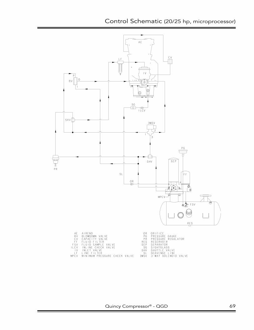
Control Schematic (20/25 hp, microprocessor)
AEBVCVFFFSVILCV
IVLF
MPCV
AIRENDBLOWDOWN VALVECAPACITY VALVEFLUID FILTERFLUID SAMPLE VALVEINLINE CHECK VALVEINLET VALVELINE FILTERMINIMUM PRESSURE CHECK VALVE
ILCV
AE
BV
CV
IV
FF
3WSV
PR
SHV
PG
RES
MPCV
SL
OR
SHV
SG
ORPGPR
RESSEPSG
SHVSL
3WSV
ORIFICEPRESSURE GAUGEPRESSURE REGULATORRESERVOIRSEPARATORSIGHTGLASSSHUTTLE VALVESCAVENGE LINE3-WAY SOLENOID VALVE
SEP
P
I
O
3
2
1
FSV
LF
Quincy Compressor® - QGD 69

Control Schematic (30 hp, gauge, full voltage)
ILCV
BV
CV
FF
3WSV
PR
SHV
PG
RES
MPCV
SL OR
SHV
SG
CV
CG
TG
PG
SEP
P
I
O
3
21
FSV
H
L
AE
IV
LEAD/LAGONLY PSPS
LF
AEBVCGCV
DPGA
DPGS
FFFSV
ILCVIVLF
MPCVORPGPRPS
RESSG
SHVSLTG
3WSV
AIRENDBLOWDOWN VALVECAPACITY GAUGECAPACITY VALVEDIFFERENTIAL PRESSUREGAUGE (AIR FILTER)DIFFERENTIAL PRESSUREGAUGE (SEPARATOR)FLUID FILTERFLUID SAMPLE VALVEINLINE CHECK VALVEINLET VALVELINE FILTERMINIMUM PRESSURE CHECK VALVEORIFICEPRESSURE GAUGEPRESSURE REGULATORPRESSURE SWITCHRESERVOIRSIGHTGLASSSHUTTLE VALVESCAVENGE LINETEMPERATURE GAUGE3-WAY SOLENOID VALVE
DPGA
DPGS
70 Quincy Compressor® - QGD

Control Schematic (30 hp, gauge, wye-delta)
ILCVBV
CV
FF
3WSV
PR
SHV
PG
RES
MPCV
SL OR
SHV
SG
CVCG
TG
PG
SEP
P
I
O
3
2
1
FSV
H
L
PS
AE
IV
PS
LEAD/LAGONLY
LF
AEBVCGCV
DPGA
DPGS
FFFSVILCV
IVLF
MPCVORPGPRPSRESSGSHVSLTG
3WSV
AIRENDBLOWDOWN VALVECAPACITY GAUGECAPACITY VALVEDIFFERENTIAL PRESSUREGAUGE (AIR FILTER)DIFFERENTIAL PRESSUREGAUGE (SEPARATOR)FLUID FILTERFLUID SAMPLE VALVEINLINE CHECK VALVEINLET VALVELINE FILTERMINIMUM PRESSURE CHECK VALVEORIFICEPRESSURE GAUGEPRESSURE REGULATORPRESSURE SWITCHRESERVOIRSIGHTGLASSSHUTTLE VALVESCAVENGE LINETEMPERATURE GAUGE3-WAY SOLENOID VALVE
DPGA
DPGS
LOWERPORT
Quincy Compressor® - QGD 71

Control Schematic (30 hp, microprocessor, full voltage)
AEBVCVFFFSVILCV
IVLF
AIRENDBLOWDOWN VALVECAPACITY VALVEFLUID FILTERFLUID SAMPLE VALVEINLINE CHECK VALVEINLET VALVELINE FILTER
ILCV
BV
CV
FF
3WSV
PR
SHV
RES
MPCV
SL
OR
SHV
SG
MPCVORPG
RESSG
SHVSL
3WSV
MINIMUM PRESSURE CHECK VALVEORIFICEPRESSURE GAUGERESERVOIRSIGHTGLASSSHUTTLE VALVESCAVENGE LINE3-WAY SOLENOID VALVE
SEP
3
2
1
FSV
AE
IV
PG
PI
O
LF
72 Quincy Compressor® - QGD

Control Schematic (30 hp, microprocessor, wye-delta)
ILCVBV
CV
FF
3WSV
PR
SHV
PG
RES
MPCV
SL
OR
SHV
SG
SEP
P
I
O
3
2
1
AE
IV
PSAEBVCVFFFSVILCV
IVLF
MPCVORPGPSRESSGSHVSL
3WSV
AIRENDBLOWDOWN VALVECAPACITY VALVEFLUID FILTERFLUID SAMPLE VALVEINLINE CHECK VALVEINLET VALVELINE FILTERMINIMUM PRESSURE CHECK VALVEORIFICEPRESSURE GAUGEPRESSURE SENSORRESERVOIRSIGHTGLASSSHUTTLE VALVESCAVENGE LINE3-WAY SOLENOID VALVE
FSV
LF
Quincy Compressor® - QGD 73

Control Schematic (40/50 hp, gauge)
ILCV
BV
CV
3WSV
PR
SHV
PG
RES
MPCV
SL
OR
SHV
SG
CVCG
TG
PG
P
I
O
PS
3
2
1
FSV
H
L
AE
IV
SEP
SEP
PSLEAD/LAG
ONLY
DPGA
DPGS
LF
AEBVCGCV
DPGA
DPGS
FFFSVILCV
IVLF
MPCVORPGPRPSRESSGSHVSLTG
3WSV
AIRENDBLOWDOWN VALVECAPACITY GAUGECAPACITY VALVEDIFFERENTIAL PRESSUREGAUGE (AIR FILTER)DIFFERENTIAL PRESSUREGAUGE (SEPARATOR)FLUID FILTERFLUID SAMPLE VALVEINLINE CHECK VALVEINLET VALVELINE FILTERMINIMUM PRESSURE CHECK VALVEORIFICEPRESSURE GAUGEPRESSURE REGULATORPRESSURE SWITCHRESERVOIRSIGHTGLASSSHUTTLE VALVESCAVENGE LINETEMPERATURE GAUGE3-WAY SOLENOID VALVE
74 Quincy Compressor® - QGD

Control Schematic (40/50 hp, microprocessor)
ILCV
BV
CV
FF3WSV
PR
SHV
PG
RES
MPCV
SL
OR
SHV
SG
P
I
O
3
2
1
AE
IV
PSSEP SEP
FSV
AEBVCVFFFSVILCV
IVLF
MPCVORPGPSRESSGSHVSL
3WSV
AIRENDBLOWDOWN VALVECAPACITY VALVEFLUID FILTERFLUID SAMPLE VALVEINLINE CHECK VALVEINLET VALVELINE FILTERMINIMUM PRESSURE CHECK VALVEORIFICEPRESSURE GAUGEPRESSURE SENSORRESERVOIRSIGHTGLASSSHUTTLE VALVESCAVENGE LINE3-WAY SOLENOID VALVE
LF
Quincy Compressor® - QGD 75

electrical Control Diagram (full voltage, auto dual)
wP2072A
NOTES1) AT INSTALLATION THE CUSTOMER IS TO PROVIDE DISCONNECT AND BRANCH CIRCUIT OVERCURRENT PROTECTION IN ACCORDANCE WITH THE NATIONAL ELECTRICAL CODE AND/OR ANY LOCAL CODES HAVING PRECEDENCE.2) UNLESS OTHERWISE SPECIFIED ALL WIRES ARE RED EXCEPT "N" WIRES ARE WHITE AND "G" WIRES ARE GREEN.3) TR1 TO BE SET TO OFF-DELAY AND HAVE A TIME SETTING OF 10-15 MINUTES.
G
POWERON
CR2
TR1
CPT1
2FU
1FU
N3FU
2
STARTSTOP
PB1PB2
3
17
CR1
1
PL1
G
CR2
1TS17 5
7
H.A.T.
RPL2
CR2
8
CR1
N9TR1
CR2 OL1
10 11M1
HM
17 N
15 16
M1
PS1
SV1UNLOAD
COMPRESSORMOTOR
MOTOR CIRCUITOVERCURRENTPROTECTIONSEE NOTE 1
POWERSUPPLY
L1 L2 L3
M1
OL1
PPR
*
18
J2
17 12
SEE TABLE
A2A1
SEE NOTE 3
6
15 18
FU FUSEPB PUSH BUTTONSS SELECTOR SWITCHCR CONTROL RELAYCPT CONTROL POWER TRANSTS TEMP. SWITCHHAT HIGH AIR TEMP.PL PANEL LIGHTTR TIMING RELAY
OL OVERLOAD RELAYM CONTACTORSV SOLENOID VALVEVS VACUUM SWITCH SCREW TERMINAL OCTAL SOCKET NUMBER OPTIONALSHM HOUR METERJ JUMPERS
NOMENCLATURE
N
*
OL4 M4
A
B
C
PHASEPROTECTION
RELAY
FU7
FU8
FU9
J1
****
INSIDE ELECTRICAL ENCLOSURE
OUTSIDE ELECTRICAL ENCLOSURE
SS1
CONTINOUSRUN
AUTODUAL
FAN MOTOR
M4
OL4
76 Quincy Compressor® - QGD

electrical Control Diagram (wye-delta, auto dual)
wP2072A1
NOTES1) AT INSTALLATION THE CUSTOMER IS TO PROVIDE DISCONNECT AND BRANCH CIRCUIT OVERCURRENT PROTECTION IN ACCORDANCE WITH THE NATIONAL ELECTRICAL CODE AND/OR ANY LOCAL CODES HAVING PRECEDENCE.2) UNLESS OTHERWISE SPECIFIED ALL WIRES ARE RED EXCEPT "N" WIRES ARE WHITE AND "G" WIRES ARE GREEN.3) TR1 TO BE SET TO OFF-DELAY AND HAVE A TIME SETTING OF 10-15 MINUTES.4) TR2 TO BE SET TO ON-DELAY AND HAVE A TIME SETTING OF 6 SECONDS.
POWERON
CR2
TR1
CPT1
2FU
1FU
N3FU
2
STARTSTOP
PB1PB2
3
17
CR1
1
PL1
G
CR2
1TS17 5
7
H.A.T.
RPL2
CR2
8
CR1
N9TR1
CR2 OL1
10 11
HM
17 N
15 16
M2
PS1
SV1UNLOAD
MOTOR CIRCUITOVERCURRENTPROTECTIONSEE NOTE 1
POWERSUPPLY
L1 L2 L3
PPR
*
18
J2
17 12
SEE TABLE
A2A1
SEE NOTE 3
6
15 18
FU FUSEPB PUSH BUTTONSS SELECTOR SWITCHCR CONTROL RELAYCPT CONTROL POWER TRANSTS TEMP. SWITCHHAT HIGH AIR TEMP.PL PANEL LIGHTTR TIMING RELAYOL OVERLOAD RELAYM CONTACTORSV SOLENOID VALVEVS VACUUM SWITCH SCREW TERMINAL OCTAL SOCKET NUMBER OPTIONALSHM HOUR METER
NOMENCLATURE
N
*
OL4 M4
*A
B
C
PHASEPROTECTION
RELAY
FU7
FU8
FU9
J1
*
**
INSIDE ELECTRICAL ENCLOSURE
OUTSIDE ELECTRICAL ENCLOSURE
M3M2
COMPRESSORMOTOR
OL1
M2
M2M3M2
TR2
TR2
TR2
22
24
24
25
A1 A2
SEE NOTE 4
15
15
16
18
M323
SS1
CONTINOUSRUN
AUTODUAL
FAN MOTOR
M4
OL4
G
Quincy Compressor® - QGD 77

electrical Control Diagram (microprocessor control, full voltage)
wP2073A
FU1
FU2
CPT
E-STOP
MOTOR CIRCUITOVERCURRENTPROTECTION(NOTE 1)
POWERSUPPLY
L1 L2 L3
*PHASE
PROTECTIONRELAY
A
B
C
1M
N
I0.0
L1
18
15M4
FUPBSSCRCPTTSHATPLCCTOLMSVPSX2*HMI
NOMENCLATURE
PLC
9
5
T3 T2 T1
OL1
BLACK
BLACK
BLACK
WHITE
WHITE
WHITECT1
CT2
CT3
*THIS CONFIGURATION USED ONLY WITH DRIVE MOTOR OVERLOAD THAT USES CT'S
FUSEPUSH BUTTONSELECTOR SWITCHCONTROL RELAYCONTROL POWER TRANSFORMERTEMPERATURE SENSORHIGH AIR TEMPERATUREPROGRAMMABLE LOGIC CONTROLLERCURRENT TRANSFORMEROVERLOAD RELAYCONTACTORSOLENOID VALVEPRESSURE SENSORSCREW TERMINALNUMBER DESIGNATOR ON DEVICEOPTIONALHUMAN MACHINE INTERFACE
M1
COMPRESSORMOTOR
FU3 N4
N
Q0.0
NOTES-UNLESS OTHERWISE SPECIFIED:1) AT INSTALLATION, CUSTOMER IS TO PROVIDE DISCONNECT AND BRANCH CIRCUIT OVERLOAD PROTECTION IN ACCORDANCE WITH THE NATIONAL ELECTRICAL CODE AND/OR ANY LOCAL CODES HAVING PRECEDENCE.2) TO ENABLE REMOTE START REMOVE J2 . UNIT MUST BE LOCALLY STARTED BEFORE REMOTE INPUT WILL WORK. WHEN CONTACT BETWEEN 17 AND 7 IS CLOSED THE UNIT WILL START.3) TO ENABLE REMOTE UNLOAD REMOVE J3. WHEN CONTACT BETWEEN 17 AND 16 IS CLOSED THE UNIT WILL LOAD.
X3
X2
X1
Q0.1
Q0.2
Q0.3
Q0.4
Q0.5
1417
I0.1
I0.2
I0.3
I0.4
I0.5
I0.6
I0.7
OL1
2
2M
1L
2L
8 M111
24
120VAC
24VAC
19FU4
120VAC
24VDC
120VAC
M
L+17
B+
A+
M
HMI
STARTSTOP
24 17
23
20 PRESSURE SENSOR4-20Ma
0-300 PSI
TEMPERATURE SENSOR4-20Ma0-300 F
1
J2
16
717
17J3
SEE NOTE 2
SEE NOTE 3
230VSINGLE PHASEPOWER SUPPLY
L1 L2
*DRYER
20/25/30HORSE POWER
UNITS
MOTOR CIRCUITOVERCURRENTPROTECTION(NOTE 1)
2
1
WHITE
RED
3
4
25
I1.0
Q0.6
X7 CR1 X6CR1
*GENERAL FAULT CONTACT
X5
*CR1GENERAL FAULT
29
Q0.7
Q1.0
Q1.1
3L24VAC
PACKAGE DRAIN
SV2
N
2
499 OHM, 1% METALFILM, 1/4 WATT
1 2
UNLOAD
3SV1
499 OHM, 1% METALFILM, 1/4 WATT
28M124
31DRYER FAULT
I1.1
I1.2
I1.3
I1.4
I1.5
PORT 0
PORT 1
J4
COMPRESSORMOTOR
HOURMETER
PB1E-STOP
*PPR
J1
J5
OL4 OL11017
DRYER RUNNING
22
30M1
13
M4
FAN MOTOR
M4
OL4
J6
78 Quincy Compressor® - QGD

electrical Control Diagram (microprocessor control, wye-delta)
wP2073B
M2M3
FU1
FU2
CPT
MOTOR CIRCUITOVERCURRENTPROTECTION(NOTE 1)
POWERSUPPLY
L1 L2 L3
*PHASE
PROTECTIONRELAY
A
B
C
1M
N
I0.0
L1
18
15M4
FUPBSSCRCPTTSHATPLCCTOLMSVPSX2*HMI
NOMENCLATURE
PLC
9
5
OL1OL4 10
COMPRESSORMOTOR
T3 T2 T1
OL1
BLACK
BLACK
BLACK
WHITE
WHITE
WHITE
CT1
CT2
CT3
*THIS CONFIGURATION USED ONLY WITH DRIVE MOTOR OVERLOAD THAT USES CT'S
FUSEPUSH BUTTONSELECTOR SWITCHCONTROL RELAYCONTROL POWER TRANSFORMERTEMPERATURE SENSORHIGH AIR TEMPERATUREPROGRAMMABLE LOGIC CONTROLLERCURRENT TRANSFORMEROVERLOAD RELAYCONTACTORSOLENOID VALVEPRESSURE SENSORSCREW TERMINALNUMBER DESIGNATOR ON DEVICEOPTIONALHUMAN MACHINE INTERFACE
M3 M2
COMPRESSORMOTOR
FU3 N4
N
Q0.0
NOTES-UNLESS OTHERWISE SPECIFIED:1) AT INSTALLATION, CUSTOMER IS TO PROVIDE DISCONNECT AND BRANCH CIRCUIT OVERLOAD PROTECTION IN ACCORDANCE WITH THE NATIONAL ELECTRICAL CODE AND/OR ANY LOCAL CODES HAVING PRECEDENCE.2) TO ENABLE REMOTE START REMOVE J2 . UNIT MUST BE LOCALLY STARTED BEFORE REMOTE INPUT WILL WORK. WHEN CONTACT BETWEEN 17 AND 7 IS CLOSED THE UNIT WILL START.3) TO ENABLE REMOTE UNLOAD REMOVE J3. WHEN CONTACT BETWEEN 17 AND 16 IS CLOSED THE UNIT WILL LOAD.4) DRYERS FOR THE 20-30HP UNITS WILL BE 220V SINGLE PHASE. DRYERS FOR THE 40-60HP UNITS WILL BE THE SAME THREE PHASE VOLTAGE AS THE UNIT.
X3
X2
X1
Q0.1
Q0.2
Q0.3
Q0.4
Q0.5
I0.1
I0.2
I0.3
I0.4
I0.5
I0.6
I0.7
OL1
2
2M
1L
2L
8M2
11
M312
24
120VAC
24VAC
19FU4
120VAC
24VDC
120VAC
M
L+17
B+
A+
M
HMI
STARTSTOP
24 17
23
20 PRESSURE SENSOR4-20Ma
0-300 PSI
TEMPERATURE SENSOR4-20Ma0-300 F
1
PB1E-STOP
J2
16
717
17J3
SEE NOTE 2
SEE NOTE 3
230VSINGLE PHASEPOWER SUPPLY
L1 L2
*DRYER
20/25/30HORSE POWER
UNITS
MOTOR CIRCUITOVERCURRENTPROTECTION(NOTE 1)
2
1
WHITE
RED
3
4
25DRYER RUNNING
I1.0
Q0.6
X7 CR1 X6CR1
GENERAL FAULT CONTACT
X5
*CR1GENERAL FAULT
29
Q0.7
Q1.0
Q1.1
3L24VAC
PACKAGE DRAIN
SV2
N
2
499 OHM, 1% METALFILM, 1/4 WATT
1 2
UNLOAD
3SV1
M3
26M2
499 OHM, 1% METALFILM, 1/4 WATT
28M224
31DRYER FAULT
I1.1
I1.2
I1.3
I1.4
I1.5
PORT 0
PORT 1
HOURMETER
J5
22
30M1
E-STOP1417 *PPR
J1
13
M4
FAN MOTOR
M4
OL4
J6
Quincy Compressor® - QGD 79

Standard Terms and Conditions
Quincy Compressor and Ortman Fluid Power Divisions
TITle & lIeN RIGhTS: The equipment shall remain personal property, regardless of how affixed to any realty or structure. until the price (including any notes given therefore) of the equipment has been fully paid in cash, Seller shall, in the event of Buyer’s default, have the right to repossess such equipment.PATeNT INFRINGMeNT: If properly notified and given an opportunity to do so with friendly assistance, Seller will defend Buyer and the ultimate user of the equipment from any actual or alleged infringement of any published united States patent by the equipment or any part thereof furnished pursuant hereto (other than parts of special design, construction, or manufacture specified by and originating with Buyer), and will pay all damages and costs awarded by competent court in any suit thus defended or of which it may have had notice and opportunity to defend as aforesaid.
STANDARD wARRANTy: Seller warrants that products of its own manufacture will be free from defects in workmanship and materials under normal use and service for the period specified in the product instruction manual. warranty for service parts will be ninety (90) days from date of factory shipment. electric Motors, gasoline and diesel engines, electrical apparatus and all other accessories, components and parts not manufactured by Seller are warranted only to the extent of the original manufacturer’s warranty.
Notice of the alleged defect must be given to the Seller, in writing with all identifying details including serial number, type of equipment and date of purchase within thirty (30) days of the discovery of the same during the warranty period.
Seller’s sole obligation on this warranty shall be, at its option, to repair or replace or refund the purchase price of any product or part thereof which proves to be defective. If requested by Seller, such product or part thereof must be promptly returned to seller, freight prepaid, for inspection.
Seller warrants repaired or replaced parts of its own manufacture against defects in materials and workmanship under normal use and service for ninety (90) days or for the remainder of the warranty on the product being repaired.
This warranty shall not apply and Seller shall not be responsible or liable for:
(a) Consequential, collateral or special losses or damages;
(b) equipment conditions caused by fair wear and tear, abnormal conditions of use, accident, neglect or misuse of equipment, improper storage or damage resulting during shipping;
(c) Deviation from operating instructions, specifications or other special terms of sale;
(d) labor charges, loss or damage resulting from improper operation, maintenance or repairs made by person(s) other than Seller or Seller’s authorized service station.
In no event shall Seller be liable for any claims whether arising from breach of contract or warranty or claims of negligence or negligent manufacture in excess of the purchase price.
ThIS wARRANTy IS The SOle wARRANTy OF SelleRS AND ANy OTheR wARRANTIeS, wheTheR eXPReSS OR IMPlIeD IN lAw OR IMPlIeD IN FACT, INCluDING ANy wARRANTIeS OF MeRChANTABIlITy AND FITNeSS FOR PARTICulAR uSe ARe heReBy SPeCIFICAlly eXCluDeD.
lIABIlITy lIMITATIONS: under no circumstances shall the Seller have any liability for liquidated damages or for collateral, consequential or special damages or for loss of profits, or for actual losses or for loss of production or progress of construction, whether resulting from delays in delivery or performance, breach of warranty, negligent manufacture or otherwise.
eNvIROMeNTAl AND OShA ReQuIReMeNTS: At the time of shipment of the equipment from the factory, Quincy Compressor / Ortman Fluid Power will comply with the various Federal, State and local laws and regulations concerning occupational health and safety and pollution. however, in the installation and operation of the equipment and other matters over which the seller has no control, the Seller assumes no responsibility for compliance with those laws and regulations, whether by the way of indemnity, warranty or otherwise.
80 Quincy Compressor® - QGD

Standard Terms and Conditions
Quincy Compressor and Ortman Fluid Power Divisions
leGAl eFFeCT: except as expressly otherwise agreed to in writing by an authorized representative of Seller, the following terms and conditions shall apply to and form a part of this order and any additional and/or different terms of Buyer’s purchase order or other form of acceptance are rejected in advance and shall not become a part of this order.
The rights of Buyer hereunder shall be neither assignable nor transferable except with the written consent of Seller.
This order may not be canceled or altered except with the written consent of Seller and upon terms which will indemnify Seller against all loss occasioned thereby. All additional costs incurred by Seller due to changes in design or specifications, modification of this order or revision of product must be paid for by Buyer.
In addition to the rights and remedies conferred upon Seller by this order, Seller shall have all rights and remedies conferred at law and in equity and shall not be required to proceed with the performance of this order if Buyer is in default in the performance of such order or of any other contract or order with seller.
TeRMS OF PAyMeNT: unless otherwise specified in the order acknowledgment, the terms of payment shall be net cash within thirty (30) days after shipment. These terms shall apply to partial as well as complete shipments. If any proceeding be initiated by or against Buyer under any bankruptcy or insolvency law, or in the judgment of Seller the financial condition of Buyer, at the time the equipment is ready for shipment, does not justify the terms of payment specified, Seller reserves the right to require full payment in cash prior to making shipment. If such payment is not received within fifteen (15) days after notification of readiness for shipment, Seller may cancel the order as to any unshipped item and require payment of its reasonable cancellation charges.
If Buyer delays shipment, payments based on date of shipment shall become due as of the date when ready for shipment. If Buyer delays completion of manufacture, Seller may elect to require payment according to percentage of completion. equipment held for Buyer shall be at Buyer’s risk and storage charges may be applied at the discretion of Seller.
Accounts past due shall bare interest at the highest rate lawful to contract for but if there is no limit set by law, such interest shall be eighteen percent (18%). Buyer shall pay all cost and expenses, including reasonable attorney’s fees, incurred in collecting the same, and no claim, except claims within Seller’s warranty of material or workmanship, as stated below, will be recognized unless delivered in writing to Seller within thirty (30) days after date of shipment.
TAXeS: All prices exclude present and future sales, use, occupation, license, excise, and other taxes in respect of manufacture, sales or delivery, all of which shall be paid by Buyer unless included in the purchase price at the proper rate or a proper exemption certificate is furnished.
ACCePTANCe: All offers to purchase, quotations and contracts of sales are subject to final acceptance by an authorized representative at Seller’s plant.
DelIveRy: except as otherwise specified in this quotation, delivery will be F. O. B. point of shipment. In the absence of exact shipping instruction, Seller will use its discretion regarding best means of insured shipment. No liability will be accepted by Seller for so doing. All transportation charges are at Buyer’s expense. Time of delivery is an estimate only and is based upon the receipt of all information and necessary approvals. The shipping schedule shall not be construed to limit seller in making commitments for materials or in fabricating articles under this order in accordance with Seller’s normal and reasonable production schedules.
Seller shall in no event be liable for delays caused by fires, acts of God, strikes, labor difficulties, acts of governmental or military authorities, delays in transportation or procuring materials, or causes of any kind beyond Seller’s control. No provision for liquidated damages for any cause shall apply under this order. Buyer shall accept delivery within thirty (30) days after receipt of notification of readiness for shipment. Claims for shortages will be deemed to have been waived if not made in writing within ten (10) days after the receipt of the material in respect of which any such shortage is claimed. Seller is not responsible for loss or damage in transit after having received “In Good Order” receipt from the carrier. All claims for loss or damage in transit should be made to the carrier.
Quincy Compressor® - QGD 81

Notes
_______________________________________________________ _______________________________________________________ _______________________________________________________ _______________________________________________________ _______________________________________________________ _______________________________________________________ _______________________________________________________ _______________________________________________________ _______________________________________________________ _______________________________________________________ _______________________________________________________ _______________________________________________________ _______________________________________________________ _______________________________________________________ _______________________________________________________ _______________________________________________________ _______________________________________________________ _______________________________________________________ _______________________________________________________ _______________________________________________________ _______________________________________________________ _______________________________________________________ _______________________________________________________ _______________________________________________________ _______________________________________________________ _______________________________________________________ _______________________________________________________ _______________________________________________________ _______________________________________________________ _______________________________________________________ _______________________________________________________ _______________________________________________________ _______________________________________________________ _______________________________________________________ _______________________________________________________ _______________________________________________________ _______________________________________________________ _______________________________________________________
82 Quincy Compressor® - QGD


© 2008 Quincy Compressor
All Rights Reserved. litho in u.S.A.
Quincy Compressor Products: 217.222.7700
e-mail: [email protected]
website: quincycompressor.com
Related Documents