N.V. Siva Rama Krishna .T et al Int. Journal of Engineering Research and Applications www.ijera.com ISSN : 2248-9622, Vol. 4, Issue 5( Version 7), May 2014, pp.92-98 www.ijera.com 92 | Page Area efficient Short Bit Width Two’s Compliment Multiplier Using CSA N.V. Siva Rama Krishna .T #1 , K .Hari Kishore *2 , K .Vinay Kumar #3 #1 Student of VLSI Systems Research Group, Department of Electronics and Communication Engineering, K L University, Guntur, AP-INDIA #2 ASSOC.Professor VLSI System Research Group, Department Of Electronics and Communication Engineering, K L University, Guntur, AP – INDIA #3 Student of VLSI Systems Research Group, Department of Electronics and Communication Engineering, K L University, Guntur, AP-INDIA Abstract Two’s complement multipliers are important for a wide range of applications. In this project, we present a technique to reduce by one row the maximum height of the partial product array generated by a radix-4 Modified Booth Encoded multiplier, without any increase in the delay of the partial product generation stage. The proposed method can be extended to higher radix encodings, as well as to the proposed approach using CSA to add partial products improve the performance by reducing area and delay; the results based on a rough theoretical analysis and on logic synthesis showed its efficiency in terms of both area and delay. And we are implementing this on CADENCE Platform in 180 nm technology. And using clock gating technique to reduce further delay Key words - Modified Booth Encoding, CSA-Carry Save Adder, partial product array I. INTRODUCTION The MAC(Multiplier and Accumulator Unit) is used for image processing and digital signal processing (DSP) in a DSP processor. Algorithm of MAC is Booth's radix-4 algorithm, wallace tree, 4:2 CSA, 64bit carry select adder and improves speed. MIPS was implemented as micro processors and permitted high performance pipeline implementations through the use of their simple register oriented instruction sets. Although those algorithms ( radix-4 algorithm, pipelining, etc ) are widely used technique for speeding up each part, the MAC on specific processor cannot be run at 100% efficiency. Due to the reasons of lower speed of MAC, MIPS instruction "mul" (multiplication) takes longer time than any other instruction in our MIPS processor. To improve speed of MIPS, MAC needs to be fast and MIPS must have special algorithm for "mul" instruction. One of the method we chose was to design multi-clock MAC instead of one-clock MAC which improved the speed of MIPS. In general, the instruction set of MIPS processor includes complex works like multiplication and floating point operation which has multi execution stage. Therefore, system clock of the processor was increased efficiently.We applied 2 stage pipelining to the MAC to MIPS processor and as a result we were able to get the result of matrix multiplication which was used. Booth Encoding The Booth encoding, or Booth algorithm, was proposed by Andrew D. Booth in 1951 This method can be used to multiply two two’s complement number without the sign bit extension. The operation of Booth encoding consists of two major steps [2]: the first one is to take one bit of the multiplier, and then to decide whether to add the multiplicand according to the current and previous bits of the multiplier. This encoding scheme is serial, which means that the different value of the 2 bits (current and previous bits) corresponds to the different operations. The serial encoding scheme is usually applied in serial multipliers. The operation procedure can be described with the following table. 00: no arithmetic operation. 01: adding the multiplicand to the left half of the product. 10: subtracting the multiplicand from the left half of the product. 11: no arithmetic operation. The second step is to shift the product right one bit. Modified Booth Encoding RESEARCH ARTICLE OPEN ACCESS

Welcome message from author
This document is posted to help you gain knowledge. Please leave a comment to let me know what you think about it! Share it to your friends and learn new things together.
Transcript

N.V. Siva Rama Krishna .T et al Int. Journal of Engineering Research and Applications www.ijera.com
ISSN : 2248-9622, Vol. 4, Issue 5( Version 7), May 2014, pp.92-98
www.ijera.com 92 | P a g e
Area efficient Short Bit Width Two’s Compliment Multiplier
Using CSA
N.V. Siva Rama Krishna .T #1
, K .Hari Kishore*2
, K .Vinay Kumar #3
#1
Student of VLSI Systems Research Group, Department of Electronics and Communication Engineering, K L
University, Guntur, AP-INDIA #2
ASSOC.Professor VLSI System Research Group, Department Of Electronics and Communication
Engineering, K L University, Guntur, AP – INDIA #3
Student of VLSI Systems Research Group, Department of Electronics and Communication Engineering, K L
University, Guntur, AP-INDIA
Abstract Two’s complement multipliers are important for a wide range of applications. In this project, we present a
technique to reduce by one row the maximum height of the partial product array generated by a radix-4
Modified Booth Encoded multiplier, without any increase in the delay of the partial product generation stage.
The proposed method can be extended to higher radix encodings, as well as to the proposed approach using
CSA to add partial products improve the performance by reducing area and delay; the results based on a rough
theoretical analysis and on logic synthesis showed its efficiency in terms of both area and delay. And we are
implementing this on CADENCE Platform in 180 nm technology. And using clock gating technique to reduce
further delay
Key words - Modified Booth Encoding, CSA-Carry Save Adder, partial product array
I. INTRODUCTION The MAC(Multiplier and Accumulator Unit)
is used for image processing and digital signal
processing (DSP) in a DSP processor. Algorithm of
MAC is Booth's radix-4 algorithm, wallace tree, 4:2
CSA, 64bit carry select adder and improves speed.
MIPS was implemented as micro processors and
permitted high performance pipeline implementations
through the use of their simple register oriented
instruction sets. Although those algorithms ( radix-4
algorithm, pipelining, etc ) are widely used technique
for speeding up each part, the MAC on specific
processor cannot be run at 100% efficiency.
Due to the reasons of lower speed of MAC,
MIPS instruction "mul" (multiplication) takes longer
time than any other instruction in our MIPS
processor. To improve speed of MIPS, MAC needs to
be fast and MIPS must have special algorithm for
"mul" instruction. One of the method we chose was
to design multi-clock MAC instead of one-clock
MAC which improved the speed of MIPS. In general,
the instruction set of MIPS processor includes
complex works like multiplication and floating point
operation which has multi execution stage. Therefore,
system clock of the processor was increased
efficiently.We applied 2 stage pipelining to the MAC
to MIPS processor and as a result we were able to get
the result of matrix multiplication which was used.
Booth Encoding
The Booth encoding, or Booth algorithm,
was proposed by Andrew D. Booth in 1951 This
method can be used to multiply two two’s
complement number without the sign bit extension.
The operation of Booth encoding consists of two
major steps [2]: the first one is to take one bit of the
multiplier, and then to decide whether to add the
multiplicand according to the current and previous
bits of the multiplier. This encoding scheme is serial,
which means that the different value of the 2 bits
(current and previous bits) corresponds to the
different operations. The serial encoding scheme is
usually applied in serial multipliers. The operation
procedure can be described with the following table.
00: no arithmetic operation.
01: adding the multiplicand to the left half of the
product.
10: subtracting the multiplicand from the left half
of the product.
11: no arithmetic operation.
The second step is to shift the product right one
bit.
Modified Booth Encoding
RESEARCH ARTICLE OPEN ACCESS
N.V. Siva Rama Krishna .T et al Int. Journal of Engineering Research and Applications www.ijera.com
ISSN : 2248-9622, Vol. 4, Issue 5( Version 7), May 2014, pp.92-98
www.ijera.com 93 | P a g e
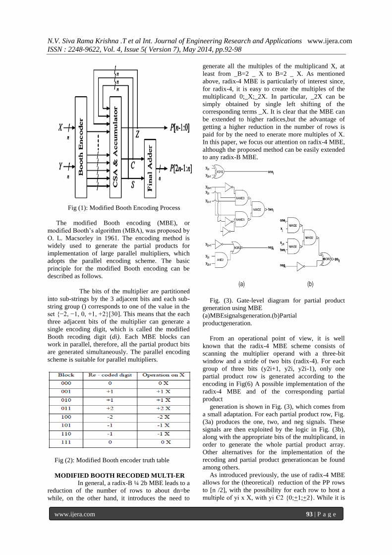
Fig (1): Modified Booth Encoding Process
The modified Booth encoding (MBE), or
modified Booth’s algorithm (MBA), was proposed by
O. L. Macsorley in 1961. The encoding method is
widely used to generate the partial products for
implementation of large parallel multipliers, which
adopts the parallel encoding scheme. The basic
principle for the modified Booth encoding can be
described as follows.
The bits of the multiplier are partitioned
into sub-strings by the 3 adjacent bits and each sub-
string group () corresponds to one of the value in the
set {−2, −1, 0, +1, +2}[30]. This means that the each
three adjacent bits of the multiplier can generate a
single encoding digit, which is called the modified
Booth recoding digit (di). Each MBE blocks can
work in parallel, therefore, all the partial product bits
are generated simultaneously. The parallel encoding
scheme is suitable for parallel multipliers.
Fig (2): Modified Booth encoder truth table
MODIFIED BOOTH RECODED MULTI-ER
In general, a radix-B ¼ 2b MBE leads to a
reduction of the number of rows to about dn=be
while, on the other hand, it introduces the need to
generate all the multiples of the multiplicand X, at
least from _B=2 _ X to B=2 _ X. As mentioned
above, radix-4 MBE is particularly of interest since,
for radix-4, it is easy to create the multiples of the
multiplicand 0;_X;_2X. In particular, _2X can be
simply obtained by single left shifting of the
corresponding terms _X. It is clear that the MBE can
be extended to higher radices,but the advantage of
getting a higher reduction in the number of rows is
paid for by the need to enerate more multiples of X.
In this paper, we focus our attention on radix-4 MBE,
although the proposed method can be easily extended
to any radix-B MBE.
Fig. (3). Gate-level diagram for partial product
generation using MBE
(a)MBEsignalsgeneration.(b)Partial
productgeneration.
From an operational point of view, it is well
known that the radix-4 MBE scheme consists of
scanning the multiplier operand with a three-bit
window and a stride of two bits (radix-4). For each
group of three bits (y2i+1, y2i, y2i-1), only one
partial product row is generated according to the
encoding in Fig(6) A possible implementation of the
radix-4 MBE and of the corresponding partial
product
generation is shown in Fig. (3), which comes from
a small adaptation. For each partial product row, Fig.
(3a) produces the one, two, and neg signals. These
signals are then exploited by the logic in Fig. (3b),
along with the appropriate bits of the multiplicand, in
order to generate the whole partial product array.
Other alternatives for the implementation of the
recoding and partial product generationcan be found
among others.
As introduced previously, the use of radix-4 MBE
allows for the (theoretical) reduction of the PP rows
to [n /2], with the possibility for each row to host a
multiple of yi x X, with yi Є2 {0;+1;+2}. While it is
N.V. Siva Rama Krishna .T et al Int. Journal of Engineering Research and Applications www.ijera.com
ISSN : 2248-9622, Vol. 4, Issue 5( Version 7), May 2014, pp.92-98
www.ijera.com 94 | P a g e
straightforward to generate the positive terms 0, X,
and 2X at least through a left shift of X, some
attention is required to generate the terms -X and -2X
which, as observed in Table 1, can arise from three
configurations of the y2i+1, y2i, and y2i-1 bits. To
avoid computing negative encodings, i.e., -X and -
2X, the two’s complement of the multiplicand is
generally used. From a mathematical point of view,
the use of two’s complement
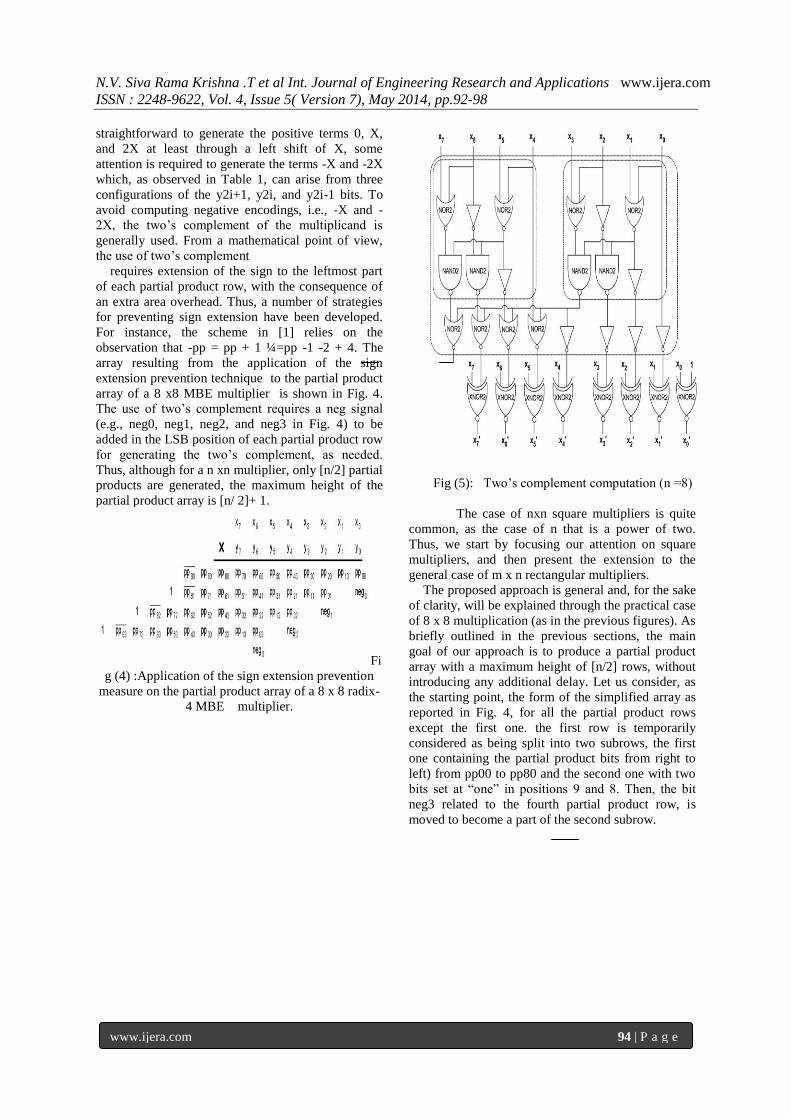
requires extension of the sign to the leftmost part
of each partial product row, with the consequence of
an extra area overhead. Thus, a number of strategies
for preventing sign extension have been developed.
For instance, the scheme in [1] relies on the
observation that -pp = pp + 1 ¼=pp -1 -2 + 4. The
array resulting from the application of the sign
extension prevention technique to the partial product
array of a 8 x8 MBE multiplier is shown in Fig. 4.
The use of two’s complement requires a neg signal
(e.g., neg0, neg1, neg2, and neg3 in Fig. 4) to be
added in the LSB position of each partial product row
for generating the two’s complement, as needed.
Thus, although for a n xn multiplier, only [n/2] partial
products are generated, the maximum height of the
partial product array is [n/ 2]+ 1.
Fi
g (4) :Application of the sign extension prevention
measure on the partial product array of a 8 x 8 radix-
4 MBE multiplier.
Fig (5): Two’s complement computation (n =8)
The case of nxn square multipliers is quite
common, as the case of n that is a power of two.
Thus, we start by focusing our attention on square
multipliers, and then present the extension to the
general case of m x n rectangular multipliers.
The proposed approach is general and, for the sake
of clarity, will be explained through the practical case
of 8 x 8 multiplication (as in the previous figures). As
briefly outlined in the previous sections, the main
goal of our approach is to produce a partial product
array with a maximum height of [n/2] rows, without
introducing any additional delay. Let us consider, as
the starting point, the form of the simplified array as
reported in Fig. 4, for all the partial product rows
except the first one. the first row is temporarily
considered as being split into two subrows, the first
one containing the partial product bits from right to
left) from pp00 to pp80 and the second one with two
bits set at “one” in positions 9 and 8. Then, the bit
neg3 related to the fourth partial product row, is
moved to become a part of the second subrow.

N.V. Siva Rama Krishna .T et al Int. Journal of Engineering Research and Applications www.ijera.com
ISSN : 2248-9622, Vol. 4, Issue 5( Version 7), May 2014, pp.92-98
www.ijera.com 95 | P a g e
Fig. (6).Gate-level diagram for the generation of
two’s complement partial product rows
(a) 3-5 decoder. (b) 4-1 multiplexer
.
Fig. (7). Partial product array by applying the
two’s complement computation method in to the last
row.
The key point of this “graphical” transformation is
that the second subrow containing also the bit neg3,
can now be easily added to the first subrow, with a
constant short carry propagation of three positions
(further denoted as “3-bits addition”), a value which
is easily shown to be general, i.e., independent of the
length of the operands, for square multipliers. In fact,
with reference to the notation of Fig.(10), we have
that qq90 qq90 qq80 qq70 qq60 = 0 0 pp80 pp70
pp60 + 0 1 1 0 neg3. As introduced above, due to the
particular value of the second operand, i.e., 0 1 1 0
neg3, in , we have observed that it requires a carry
propagation only across the least-significant three
positions, a fact that can also be seen by
theimplementation shown in Fig. (9).
It is worth observing that, in order not to
have delay penalizations, it is necessary that the
generation of the other rows is done in parallel with
the generation of the first row cascaded by the
computation of the bits qq90 qq90 qq80 qq70 qq60 in
Fig. (8b). In order to achieve this, we must simplify
and differentiate the generation of the first row with
respect to the other rows. We observe that the Booth
recoding for the first row is computed more easily
than for
the other rows, because the y_1 bit used by the
MBE is always equal to zero. In order to have a
preliminary .
. Fig (8): Partial product array after adding the
last neg bit to the first row. (a) Basic idea. (b)
Resulting array.
Fig. (9): Gate-level diagram of the proposed
method for adding the last neg bit in the first row.
In order to have a preliminary analysis which is
possibly independent of technological details, we
refer to the circuits in the following figures:
Fig. (3), slightly adapted for the partial
product generation using MBE;
Fig.(9), obtained through manual synthesis
(aimed at modularity and area reduction
without compromising the delay), for the
addition of the last neg bit to the three most
significant bits of the first row;
Fig.(10), obtained by simplifying Fig. 1
(since, in the first row, it is y2i-1 = 0), for
the partial product generation of the first
row only using MBE; and

N.V. Siva Rama Krishna .T et al Int. Journal of Engineering Research and Applications www.ijera.com
ISSN : 2248-9622, Vol. 4, Issue 5( Version 7), May 2014, pp.92-98
www.ijera.com 96 | P a g e
Fig.(11), obtained through manual synthesis of a
combination of the two parts of Fig. (10) and aimed
at decreasing the delay of Fig.(10) with no or very
small area increase, for the partial product generation
of the first row only using MBE.
In particular, we observe that, by direct
comparison of Figs. (5) and (12), the generation of
the MBE signals for the first row is simpler, and
theoretically allows for the saving of the delay of
oneNAND3gate. In addition, the implementation in
Fig. (13) has a delay that is smaller than the two parts
of Fig. (12), although it could require a small amount
of additional area. As we see in the following, this
issue hardly has any significant impact on the overall
design, since this extra hardware is used only for the
three most significant bits of the first row, and not for
all the other bits of the array.
Fig. (10): Gate-level diagram for first row partial
product generation.
(a)MBE signals generation. (b) Partial product
generation.
Fig. (11): Combined MBE signals and partial
product generation for the firstrow (improved for
speed).
The high-level description of our idea is as follows:
1. generation of the three most significant bit
weights of the first row, plus addition of the
last neg bit:possible implementations can
use a replication of three times the circuit of
Fig. 13 (each for the three most significant
bits of the first row), cascaded by the circuit
of Fig. (11) to add the neg signal;
2. parallel generation of the other bits of the
first row: possible implementations can use
instances of the circuitry depicted in Fig.
(12), for each bit of the first row, except for
the three most significant;
3. parallel generation of the bits of the other
rows: possible implementations can use the
circuitry of Fig.(5), replicated for each bit
of the other rows. All items 1 to 3 are
independent, and therefore can be executed
in parallel. Clearly if, as assumed and
expected, item 1 is not the bottleneck (i.e.,
the critical path), then the implementation of
the proposed idea has reached the goal of
not introducing time penalties.
VERIFICATION AND RESULTS
Fig (12): multiplier using ripple carry
adder (existing ) according to fig3(a)
and fig3(b)
N.V. Siva Rama Krishna .T et al Int. Journal of Engineering Research and Applications www.ijera.com
ISSN : 2248-9622, Vol. 4, Issue 5( Version 7), May 2014, pp.92-98
www.ijera.com 97 | P a g e
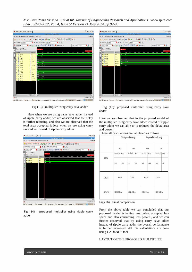
Fig (13) : multiplier using carry save adder
Here when we are using carry save adder instead
of ripple carry adder, we are observed that the delay
is further reducing, and also we are observed that the
total area occupied is less when we are using carry
save adder instead of ripple carry adder
Fig (14) : proposed multiplier using ripple carry adder
Fig (15): proposed multiplier using carry save
adder
Here we are observed that in the proposed model of
the multiplier using carry save adder instead of ripple
carry adder we can able to to reduced the delay area
and power.
These all calculations are tabulated as follows
Fig (16) : Final comparison
From the above table we can concluded that our
proposed model is having less delay, occupied less
space and also consuming less power , and we can
further observed that by using carry save adder
instead of ripple carry adder the overall performance
is further increased. All this calculations are done
using CADENCE tool
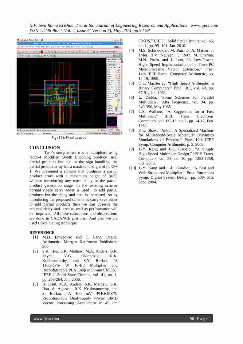
LAYOUT OF THE PROPOSED MULTIPLIER
N.V. Siva Rama Krishna .T et al Int. Journal of Engineering Research and Applications www.ijera.com
ISSN : 2248-9622, Vol. 4, Issue 5( Version 7), May 2014, pp.92-98
www.ijera.com 98 | P a g e
Fig (17): Final Layout
CONCLUSION Two’s complement n x n multipliers using
radix-4 Modified Booth Encoding produce [n/2]
partial products but due to the sign handling, the
partial product array has a maximum height of [n /2]+
1. We presented a scheme that produces a partial
product array with a maximum height of [n/2],
without introducing any extra delay in the partial
product generation stage. In the existing scheme
normal ripple carry adder is used to add partial
products but the delay and area is increased so by
introducing the proposed scheme as carry save adder
to add partial products then we can observe the
reduced delay and area as well as performance will
be improved. All these calucations and observations
are done in CADANCE platform. And also we are
used Clock Gating technique.
REFERENCE
[1] M.D. Ercegovac and T. Lang, Digital
Arithmetic. Morgan Kaufmann Publishers,
200
[2] S.K. Hsu, S.K. Mathew, M.A. Anders, B.R.
Zeydel, V.G. Oklobdzija, R.K.
Krishnamurthy, and S.Y. Borkar, “A
110GOPS/ W 16-Bit Multiplier and
Reconfigurable PLA Loop in 90-nm CMOS,”
IEEE J. Solid State Circuits, vol. 41, no. 1,
pp. 256-264, Jan. 2006.
[3] H. Kaul, M.A. Anders, S.K. Mathew, S.K.
Hsu, A. Agarwal, R.K. Krishnamurthy, and
S. Borkar, “A 300 mV 494GOPS/W
Reconfigurable Dual-Supply 4-Way SIMD
Vector Processing Accelerator in 45 nm
CMOS,” IEEE J. Solid State Circuits, vol. 45,
no. 1, pp. 95- 101, Jan. 2010.
[4] M.S. Schmookler, M. Putrino, A. Mather, J.
Tyler, H.V. Nguyen, C. Roth, M. Sharma,
M.N. Pham, and J. Lent, “A Low-Power,
High- Speed Implementation of a PowerPC
Microprocessor Vector Extension,” Proc.
14th IEEE Symp. Computer Arithmetic, pp.
12-19, 1999.
[5] O.L. MacSorley, “High Speed Arithmetic in
Binary Computers,” Proc. IRE, vol. 49, pp.
67-91, Jan. 1961.
[6] L. Dadda, “Some Schemes for Parallel
Multipliers,” Alta Frequenza, vol. 34, pp.
349-356, May 1965.
[7] C.S. Wallace, “A Suggestion for a Fast
Multiplier,” IEEE Trans. Electronic
Computers, vol. EC-13, no. 1, pp. 14-17, Feb.
1964.
[8] D.E. Shaw, “Anton: A Specialized Machine
for Millisecond-Scale Molecular Dynamics
Simulations of Proteins,” Proc. 19th IEEE
Symp. Computer Arithmetic, p. 3, 2009.
[9] J.-Y. Kang and J.-L. Gaudiot, “A Simple
High-Speed Multiplier Design,” IEEE Trans.
Computers, vol. 55, no. 10, pp. 1253-1258,
Oct. 2006.
[10] J.-Y. Kang and J.-L. Gaudiot, “A Fast and
Well-Structured Multiplier,” Proc. Euromicro
Symp. Digital System Design, pp. 508- 515,
Sept. 2004.