The Trusted Source ® Q-Series Electric Winch Assembly and Installation Manual # 92122.200X REQUIRED TOOLS: SAFETY GLASSES GLOVES TORQUE WRENCH 10 MM SOCKET 10 MM WRENCH 13 MM WRENCH 14 MM WRENCH 4 MM HEX (ALLEN ® ) KEY 5 MM HEX (ALLEN ® ) KEY P2 PHILLIPS HEAD SCREW DRIVER NEEDLE NOSE PLIERS READ ALL SAFETY MESSAGES AND UNDERSTAND ALL INSTRUCTIONS AND PROCEDURE NOTICES BEFORE ATTEMPTING TO INSTALL OR USE THIS PRODUCT.

Welcome message from author
This document is posted to help you gain knowledge. Please leave a comment to let me know what you think about it! Share it to your friends and learn new things together.
Transcript
The Trusted Source
®
Q-Series Electric WinchAssembly and Installation Manual
#92122.200X
REQUIRED TOOLS:SAFETY GLASSESGLOVESTORQUE WRENCH10 MM SOCKET10 MM WRENCH
13 MM WRENCH14 MM WRENCH4 MM HEX (ALLEN®) KEY5 MM HEX (ALLEN®) KEYP2 PHILLIPS HEAD SCREW DRIVERNEEDLE NOSE PLIERS
READ ALL SAFETY MESSAGES AND UNDERSTAND ALL INSTRUCTIONS AND PROCEDURE NOTICES BEFORE ATTEMPTING TO INSTALL OR USE THIS PRODUCT.
HRM_92112_200X_Assembly_12P_Layout 1 2/8/12 4:51 PM Page 1
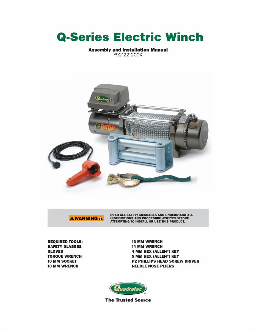
Winch ControllerConnectedto Solenoid Assembly
Solenoid Assembly
Tie Bar ClutchHandle
Cable Assembly
Winch Base
Winch Controller
The Trusted Source
®
2
Unpacking: When unpacking, check to make sure all parts are included. If any part is missing or
broken, please call Quadratec Customer Service at 800-745-6037 as soon as possible.
A Few Words About Product Safety: Your safety and the safety of others is
very important To help you avoid risks
and make informed decisions this manual
contains safety messages about your
Q-Series self-recovery winch. Individual
safety messages and sections of this
manual may be preceded by the safety
alert symbol ! [in triangle] and one of
three signal words:
You CAN be KILLED or SERIOUSLY HURT if you don’t follow instructions.
You CAN be HURT if you don’t follow instructions.
Other important information regarding a safe assembly or operation procedure may be emphasized by a NOTICE signal.
HRM_92112_200X_Assembly_12P_Layout 1 2/8/12 4:51 PM Page 2
The Trusted Source
®
3
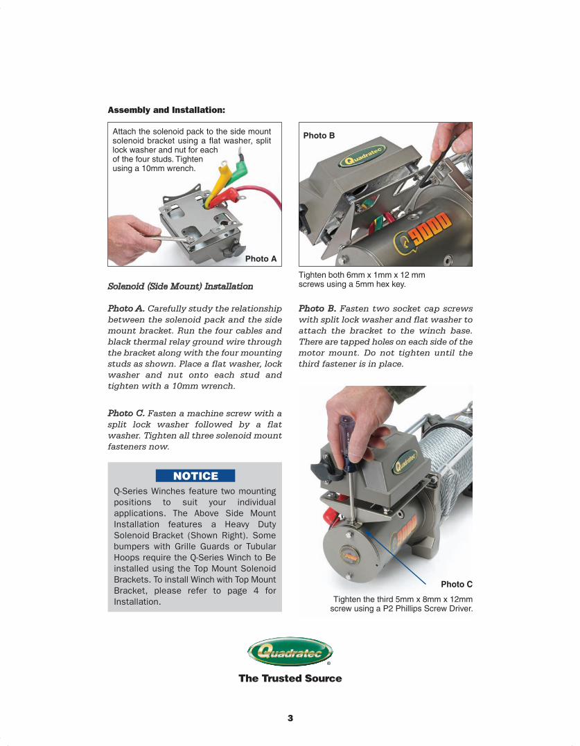
Assembly and Installation:
Solenoid (Side Mount) Installation
Photo A. Carefully study the relationship
between the solenoid pack and the side
mount bracket. Run the four cables and
black thermal relay ground wire through
the bracket along with the four mounting
studs as shown. Place a flat washer, lock
washer and nut onto each stud and
tighten with a 10mm wrench.
Photo B. Fasten two socket cap screws
with split lock washer and flat washer to
attach the bracket to the winch base.
There are tapped holes on each side of the
motor mount. Do not tighten until the
third fastener is in place.
Attach the solenoid pack to the side mountsolenoid bracket using a flat washer, splitlock washer and nut for each of the four studs. Tighten using a 10mm wrench.
Photo A
Photo B
Tighten both 6mm x 1mm x 12 mmscrews using a 5mm hex key.
Photo C
Tighten the third 5mm x 8mm x 12mmscrew using a P2 Phillips Screw Driver.
Photo C. Fasten a machine screw with a
split lock washer followed by a flat
washer. Tighten all three solenoid mount
fasteners now.
Q-Series Winches feature two mountingpositions to suit your individual applications. The Above Side Mount Installation features a Heavy Duty Solenoid Bracket (Shown Right). Somebumpers with Grille Guards or TubularHoops require the Q-Series Winch to Beinstalled using the Top Mount SolenoidBrackets. To install Winch with Top MountBracket, please refer to page 4 for Installation.
HRM_92112_200X_Assembly_12P_Layout 1 2/8/12 4:51 PM Page 3
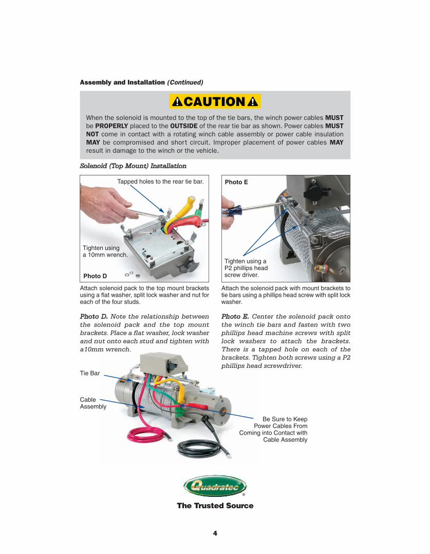
Tie Bar
Be Sure to Keep Power Cables From
Coming into Contact withCable Assembly
Cable Assembly
The Trusted Source
®
4
Tapped holes to the rear tie bar.
Tighten using a 10mm wrench.
Tighten using aP2 phillips headscrew driver.
Attach solenoid pack to the top mount bracketsusing a flat washer, split lock washer and nut foreach of the four studs.
Photo D
Photo E
Attach the solenoid pack with mount brackets totie bars using a phillips head screw with split lockwasher.
Assembly and Installation (Continued)
When the solenoid is mounted to the top of the tie bars, the winch power cables MUSTbe PROPERLY placed to the OUTSIDE of the rear tie bar as shown. Power cables MUSTNOT come in contact with a rotating winch cable assembly or power cable insulationMAY be compromised and short circuit. Improper placement of power cables MAY result in damage to the winch or the vehicle.
Photo D. Note the relationship between
the solenoid pack an d the top mount
brackets. Place a flat washer, lock washer
and nut onto each stud and tighten with
a10mm wrench.
Photo E. Center the solenoid pack onto
the winch tie bars and fasten with two
phillips head machine screws with split
lock washers to attach the brackets.
There is a tapped hole on each of the
brackets. Tighten both screws using a P2
phillips head screwdriver.
Solenoid (Top Mount) Installation
HRM_92112_200X_Assembly_12P_Layout 1 2/8/12 4:51 PM Page 4
The Trusted Source
®
5
Assembly and Installation (Continued)
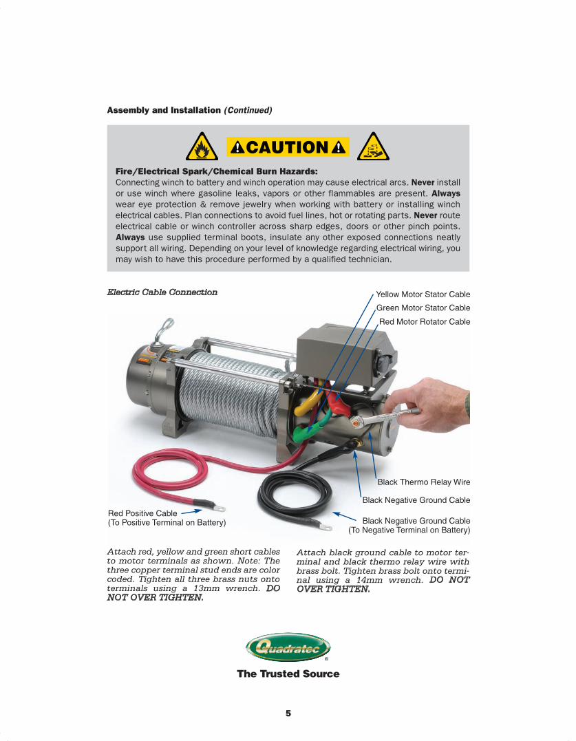
Yellow Motor Stator Cable
Green Motor Stator Cable
Red Motor Rotator Cable
Black Thermo Relay Wire
Black Negative Ground Cable
Red Positive Cable (To Positive Terminal on Battery) Black Negative Ground Cable
(To Negative Terminal on Battery)
Attach red, yellow and green short cablesto motor terminals as shown. Note: Thethree copper terminal stud ends are colorcoded. Tighten all three brass nuts ontoterminals using a 13mm wrench. DONOT OVER TIGHTEN.
Attach black ground cable to motor ter-minal and black thermo relay wire withbrass bolt. Tighten brass bolt onto termi-nal using a 14mm wrench. DO NOTOVER TIGHTEN.
Fire/Electrical Spark/Chemical Burn Hazards: Connecting winch to battery and winch operation may cause electrical arcs. Never installor use winch where gasoline leaks, vapors or other flammables are present. Alwayswear eye protection & remove jewelry when working with battery or installing winch electrical cables. Plan connections to avoid fuel lines, hot or rotating parts. Never routeelectrical cable or winch controller across sharp edges, doors or other pinch points. Always use supplied terminal boots, insulate any other exposed connections neatlysupport all wiring. Depending on your level of knowledge regarding electrical wiring, youmay wish to have this procedure performed by a qualified technician.
Electric Cable Connection
HRM_92112_200X_Assembly_12P_Layout 1 2/8/12 4:51 PM Page 5
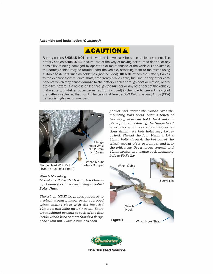
Winch Mounting
Mount the Roller Fairlead to the Mount-
ing Frame (not included) using supplied
Bolts, Nuts.
The winch MUST be properly secured to
a winch mount bumper or an approved
winch mount plate with the included
10m nuts and bolts (qty. 4 / each). There
are machined pockets at each of the four
inside winch base corners that fit a flange
head whiz nut. Place a nut into each
pocket and center the winch over the
mounting base holes. Hint: a touch of
bearing grease can hold the 4 nuts in
place prior to fastening the flange head
whiz bolts. In some rare mounting situa-
tions drilling for bolt holes may be re-
quired. Thread the four 10mm x 1.5 x
35mm bolts through the bottom of the
winch mount plate or bumper and into
the whiz nuts. Use a torque wrench and
10mm socket and torque each mounting
bolt to 50 Ft-lbs.
The Trusted Source
®
6
Assembly and Installation (Continued)
FlangeHead WhizNut (10mmx 1.5mm)
Flange Head Whiz Bolt(10mm x 1.5mm x 35mm)
Winch Cable
Cotter Pin
Winch Hook
Winch Hook Strap
Winch Mount Plate or Bumper
Figure 1
Battery cables SHOULD NOT be drawn taut. Leave slack for some cable movement. Thebattery cables SHOULD BE secure, out of the way of moving parts, road debris, or anypossibility of being damaged by operation or maintenance of the vehicle. For example,the battery cables may be routed under the vehicle, attaching them to the frame usingsuitable fasteners such as cable ties (not included). DO NOT attach the Battery Cablesto the exhaust system, drive shaft, emergency brake cable, fuel line, or any other com-ponents which may cause damage to the battery cables through heat or motion, or cre-ate a fire hazard. If a hole is drilled through the bumper or any other part of the vehicle,make sure to install a rubber grommet (not included) in the hole to prevent fraying ofthe battery cables at that point. The use of at least a 650 Cold Cranking Amps (CCA)battery is highly recommended.
HRM_92112_200X_Assembly_12P_Layout 1 2/8/12 4:52 PM Page 6
Winch Hook Assembly
Pull the Cable through the Fairlead and
connect the Hook and Safety Pin. Attach
winch hook to the winch cable as shown
using the cotter pin. Spread the cotter pin
ends to secure the hook.
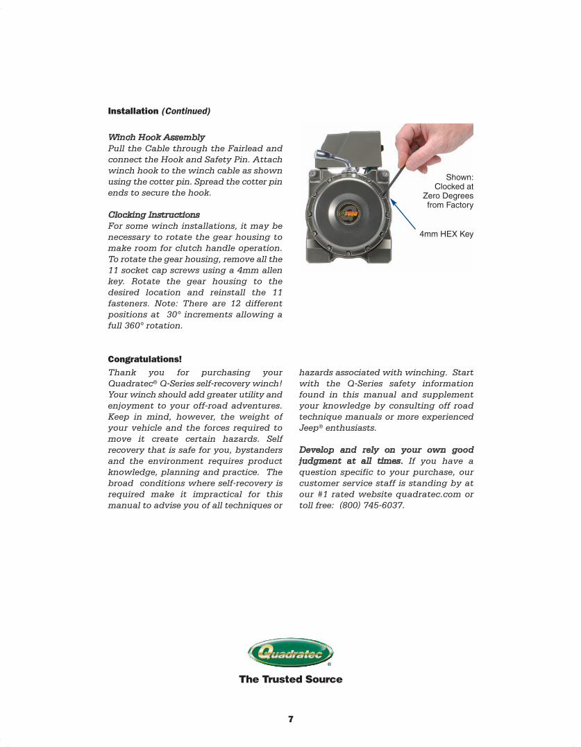
Clocking Instructions
For some winch installations, it may be
necessary to rotate the gear housing to
make room for clutch handle operation.
To rotate the gear housing, remove all the
11 socket cap screws using a 4mm allen
key. Rotate the gear housing to the
desired location and reinstall the 11
fasteners. Note: There are 12 different
positions at 30° increments allowing a
full 360° rotation.
Thank you for purchasing your
Quadratec® Q-Series self-recovery winch!
Your winch should add greater utility and
enjoyment to your off-road adventures.
Keep in mind, however, the weight of
your vehicle and the forces required to
move it create certain hazards. Self
recovery that is safe for you, bystanders
and the environment requires product
knowledge, planning and practice. The
broad conditions where self-recovery is
required make it impractical for this
manual to advise you of all techniques or
hazards associated with winching. Start
with the Q-Series safety information
found in this manual and supplement
your knowledge by consulting off road
technique manuals or more experienced
Jeep® enthusiasts.
Develop and rely on your own good
judgment at all times. If you have a
question specific to your purchase, our
customer service staff is standing by at
our #1 rated website quadratec.com or
toll free: (800) 745-6037.
The Trusted Source
®
7
Installation (Continued)
Congratulations!
Shown: Clocked at
Zero Degrees from Factory
4mm HEX Key
HRM_92112_200X_Assembly_12P_Layout 1 2/8/12 4:52 PM Page 7
The Trusted Source
®
8
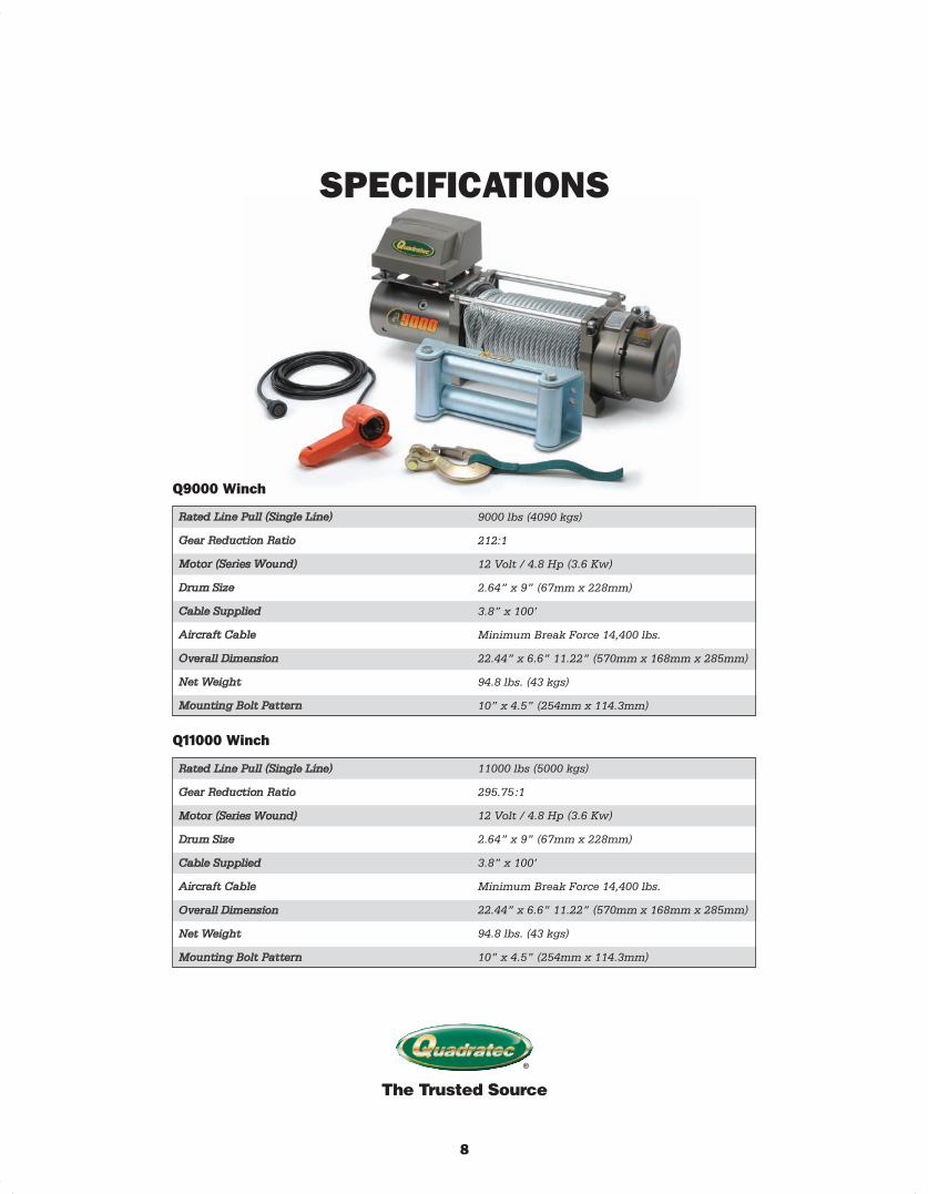
SPECIFICATIONS
Rated Line Pull (Single Line)
Gear Reduction Ratio
Motor (Series Wound)
Drum Size
Cable Supplied
Aircraft Cable
Overall Dimension
Net Weight
Mounting Bolt Pattern
9000 lbs (4090 kgs)
212:1
12 Volt / 4.8 Hp (3.6 Kw)
2.64” x 9” (67mm x 228mm)
3.8” x 100’
Minimum Break Force 14,400 lbs.
22.44” x 6.6” 11.22” (570mm x 168mm x 285mm)
94.8 lbs. (43 kgs)
10” x 4.5” (254mm x 114.3mm)
Q9000 Winch
Rated Line Pull (Single Line)
Gear Reduction Ratio
Motor (Series Wound)
Drum Size
Cable Supplied
Aircraft Cable
Overall Dimension
Net Weight
Mounting Bolt Pattern
Q11000 Winch
11000 lbs (5000 kgs)
295.75:1
12 Volt / 4.8 Hp (3.6 Kw)
2.64” x 9” (67mm x 228mm)
3.8” x 100’
Minimum Break Force 14,400 lbs.
22.44” x 6.6” 11.22” (570mm x 168mm x 285mm)
94.8 lbs. (43 kgs)
10” x 4.5” (254mm x 114.3mm)
HRM_92112_200X_Assembly_12P_Layout 1 2/8/12 4:52 PM Page 8
The Trusted Source
®
9
Revised 2 / 2012
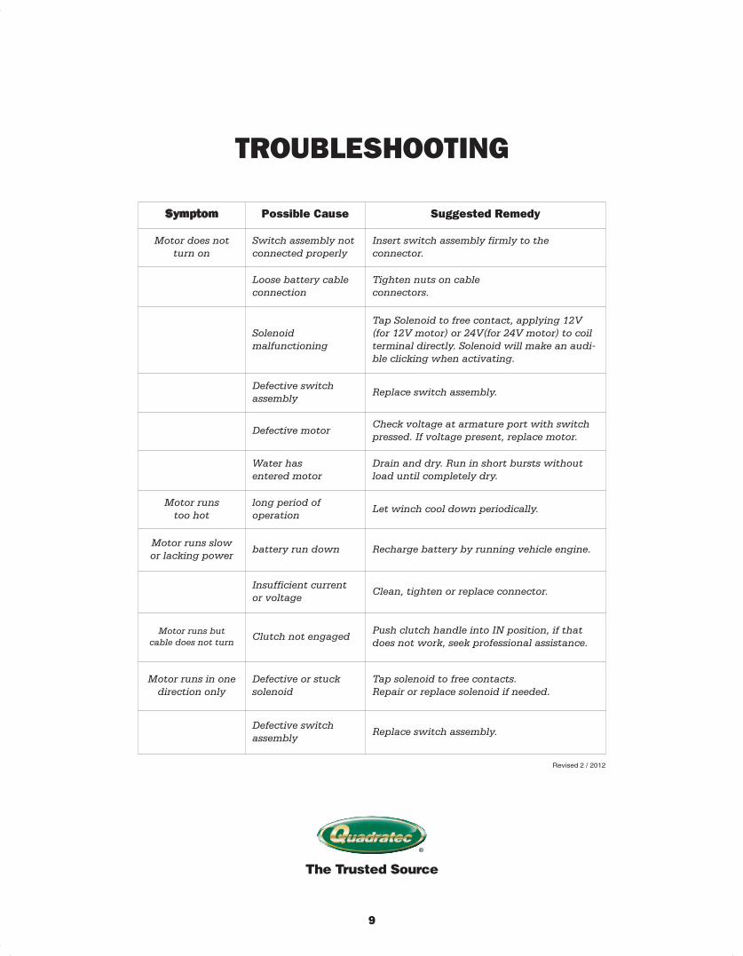
Symptom Possible Cause Suggested Remedy
Motor does not
turn on
Switch assembly not
connected properly
Insert switch assembly firmly to the
connector.
Loose battery cable
connection
Tighten nuts on cable
connectors.
Solenoid
malfunctioning
Tap Solenoid to free contact, applying 12V
(for 12V motor) or 24V(for 24V motor) to coil
terminal directly. Solenoid will make an audi-
ble clicking when activating.
Defective switch
assemblyReplace switch assembly.
Defective motorCheck voltage at armature port with switch
pressed. If voltage present, replace motor.
Water has
entered motor
Drain and dry. Run in short bursts without
load until completely dry.
Motor runs
too hot
long period of
operationLet winch cool down periodically.
Motor runs slow
or lacking powerbattery run down Recharge battery by running vehicle engine.
Insufficient current
or voltageClean, tighten or replace connector.
Motor runs but
cable does not turnClutch not engaged
Push clutch handle into IN position, if that
does not work, seek professional assistance.
Motor runs in one
direction only
Defective or stuck
solenoid
Tap solenoid to free contacts.
Repair or replace solenoid if needed.
Defective switch
assemblyReplace switch assembly.
TROUBLESHOOTING
HRM_92112_200X_Assembly_12P_Layout 1 2/8/12 4:52 PM Page 9

____________________________
____________________________
____________________________
____________________________
____________________________
____________________________
____________________________
____________________________
____________________________
____________________________
____________________________
____________________________
____________________________
____________________________
____________________________
____________________________
____________________________
____________________________
____________________________
____________________________
____________________________
____________________________
____________________________
____________________________
____________________________
____________________________
____________________________
____________________________
____________________________
____________________________
____________________________
____________________________
____________________________
____________________________
____________________________
____________________________
____________________________
____________________________
____________________________
____________________________
____________________________
____________________________
____________________________
____________________________
____________________________
____________________________
____________________________
____________________________
____________________________
____________________________
____________________________
____________________________
____________________________
____________________________
____________________________
____________________________
____________________________
____________________________
____________________________
____________________________
____________________________
____________________________
____________________________
____________________________
____________________________
____________________________
____________________________
____________________________
The Trusted Source
®
10
INSTALLATION NOTES
HRM_92112_200X_Assembly_12P_Layout 1 2/8/12 4:52 PM Page 10
Your Q-series self-recovery winch is covered by the
following Limited Warranty provided exclusively
by Quadratec, Inc., 1028 Saunders Lane,
West Chester PA 19380.
This Limited Warranty is the only warranty made
in connection with purchase. Quadratec® neither
assumes nor authorizes any vendor, retailer or
other person or entity to assume for it any other
obligation or liability in connection with this
product or Limited Warranty.
What is Covered:
LIFETIME MECHANICAL & 1 Year Electrical
Subject to the terms, exclusions and limitations
herein and with respect only to winches first sold
in the United States, Quadratec® warrants to the
initial retail purchaser only that your Q-series
winch shall be free of defects in material and
workmanship: (a.) for so long as your Q-Series
winch is owned by the initial retail purchaser with
respect to mechanical and other non-electrical
components and (b.) for a period of 1 year from
date of purchase with respect to all electrical com-
ponents (ex: motor, solenoid & control). All other
warranties are hereby disclaimed, except to the
extent prohibited by applicable law in which case
any implied warranty of merchantability or fitness
for a particular purpose on this product is limited
to 1 year from date of initial retail sale.
Quadratec® reserves the rights to: (a.) require in-
voice or other proof your winch is within the terms
of this Limited Warranty as a condition of
warranty service and, (b.) make future revisions
to this product and Limited Warranty without
prior notice or obligation to upgrade your winch.
What is Not Covered:
Your Quadratec® Limited Warranty does not cover
products or parts Quadratec® determines to have
been damaged by or subjected to: (a.) installation
damage, alteration, modification, failure to main-
tain or attempted repair or service by anyone not
authorized by Quadratec®, (b.) normal wear &
tear, cosmetic damage or damage from moisture or
water immersion, (c.) Acts of God, accidents, mis-
use (including overload & continuous pulls),
negligence, inadequate mounting or impact
with vehicle(s), obstacles or other aspects of the
environment, (d.) theft, vandalism or other
intentional damage.
Remedy Limited to Repair/Replacement:
The exclusive remedy provided hereunder shall,
upon Quadratec® inspection and at Quadratec’s
option, be either repair or replacement of product
or parts (new or refurbished) covered under this
Limited Warranty.
Customers requesting warranty consideration on
Q-series self-recovery winches should first contact
Quadratec® to obtain a RGA number
(610-701-3336). All labor, removal, shipping and
installation costs are customer’s responsibility.
Other Limitations - Exclusion of Damages
- Your Rights Under State Law:
In consideration of the purchase price paid, nei-
ther Quadratec® nor any independent Quadratec®
distributor/licensee are responsible for any time
loss, rental costs, or for any incidental, consequen-
tial, punitive or other damages you may have or
incur in connection with any part or product pur-
chased. Your exclusive remedy hereunder for cov-
ered parts is repair/replacement as described
above.
This Limited Warranty gives you specific rights.
You may also have other rights that vary from
state to state. For example, some states do not
allow Limitations of how long an implied war-
ranty lasts and /or do not allow the exclusion or
limitation of incidental or consequential damages,
so the limitations and exclusions herein may not
apply to you.
Note: An extra glovebox copy of above warranty
information is supplied on a separate 5” x 7” card.
Please retain for your records.
©Quadratec, Inc. 2012. All Rights Reserved.
The Trusted Source
®
11
Quadratec® Limited Warranty for Q-Series Self-Recovery Winches
HRM_92112_200X_Assembly_12P_Layout 1 2/8/12 4:52 PM Page 11

The Trusted Source
®
HRM_92112_200X_Assembly_12P_Layout 1 2/8/12 4:52 PM Page 12
Related Documents