1 © 2003 Cisco Systems, Inc. All rights reserved. Session Number Presentation_ID WiMAX Overview WiMAX Overview Parviz Yegani Cisco Systems [email protected] IETF-64 Nov. 7-11, 2005 Vancouver, Canada

Welcome message from author
This document is posted to help you gain knowledge. Please leave a comment to let me know what you think about it! Share it to your friends and learn new things together.
Transcript
1© 2003 Cisco Systems, Inc. All rights reserved.Session NumberPresentation_ID
WiMAX OverviewWiMAX Overview
Parviz YeganiCisco [email protected]
IETF-64Nov. 7-11, 2005Vancouver, Canada

222© 2003 Cisco Systems, Inc. All rights reserved.Presentation_ID
Outline
WiMAX NWG GoalsNetwork Reference ModelReference Points and InterfacesNWG Release 1 FeaturesImplementation ScenariosUsage Modes (Fixed, Nomadic, Mobile)Quality of Service (QoS)Mobility Management (MM)SecurityNext Steps

333© 2003 Cisco Systems, Inc. All rights reserved.Presentation_ID
WiMAX NWG Goals
Network WG was formed to create an open end-to-end framework for interoperable WiMAX networks, satisfying operators’ business requirements for multi-vendor interoperability. NWG specification will include the following:
Normative use of protocols and procedures to satisfy various functions of a working system based on existing IEEE and IETF standards
Protocols and procedures defined over various interfaces for different capabilities supported by the network
A unified approach from which interoperable profilescan be derived for basic interoperability for different usage modes and service models
444© 2003 Cisco Systems, Inc. All rights reserved.Presentation_ID
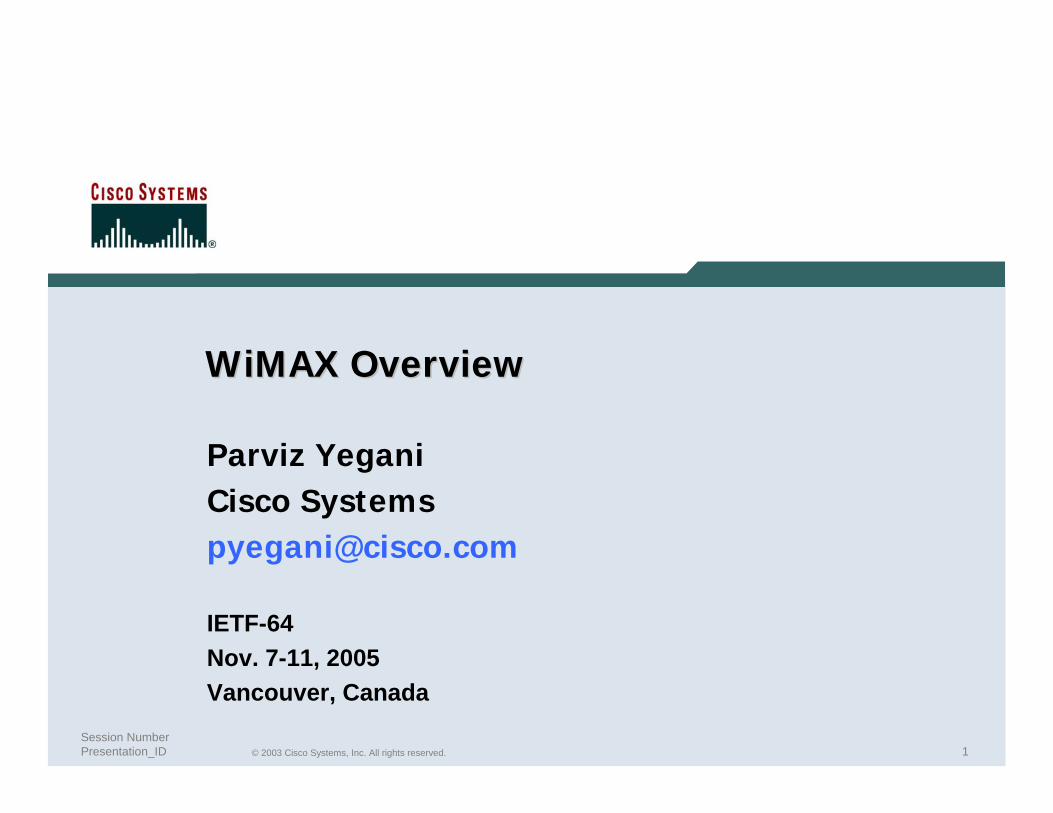
Network Reference Architecture
.
MS
ASN
R8
R6
NSP
R1 R3
ASN GW
R8 R4
R2
home CSN
R5 (Roaming)
R6
ASN GW(FA)
BS
NAP
visited CSN
HA AAA
BS
open
closed
Architecture allows multiple implementation options for a given functional entity, and yet achieve interoperability among different realizations of functional entities
555© 2003 Cisco Systems, Inc. All rights reserved.Presentation_ID
Interfaces …
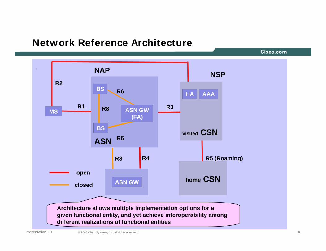
R1 – the interface between the MS and the ASN as per the air interface (PHY and MAC) specifications (IEEE P802.16d/e). R1 may include additional protocols related to the management plane.
R2 – the interface between the MS and CSN associated with Authentication, Services Authorization, IP Host Configuration management, and mobility management. This is a logical interface thus does not reflect a direct protocol interface between MS and CSN.
R3 – the interface between the ASN and the CSN to support AAA, policy enforcement and mobility management capabilities. It also encompasses the bearer plane methods (e.g., tunneling) to transfer IP data between the ASN and the CSN.
666© 2003 Cisco Systems, Inc. All rights reserved.Presentation_ID
Interfaces …
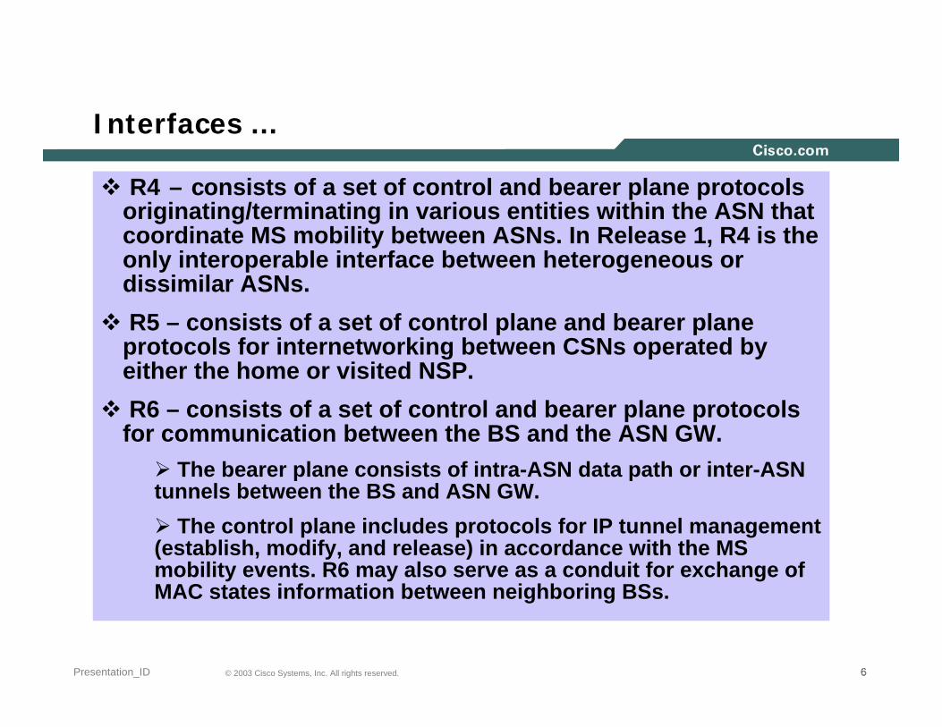
R4 – consists of a set of control and bearer plane protocols originating/terminating in various entities within the ASN that coordinate MS mobility between ASNs. In Release 1, R4 is the only interoperable interface between heterogeneous or dissimilar ASNs.R5 – consists of a set of control plane and bearer plane
protocols for internetworking between CSNs operated by either the home or visited NSP. R6 – consists of a set of control and bearer plane protocols
for communication between the BS and the ASN GW. The bearer plane consists of intra-ASN data path or inter-ASN
tunnels between the BS and ASN GW. The control plane includes protocols for IP tunnel management
(establish, modify, and release) in accordance with the MS mobility events. R6 may also serve as a conduit for exchange of MAC states information between neighboring BSs.

777© 2003 Cisco Systems, Inc. All rights reserved.Presentation_ID
Interfaces
R8 – consists of a set of control plane message flows and, in some situations, bearer plane data flows between the base stations to ensure fast and seamless handover.
bearer plane consists of protocols that allow the data transfer between Base Stations involved in handover of a certain MS.
control plane consists of the inter-BS communication protocol defined in IEEE 802.16 and additional set of protocols that allow controlling the data transfer between the Base Stations involved in handover of a certain MS.

888© 2003 Cisco Systems, Inc. All rights reserved.Presentation_ID
Interoperability Framework
Main goals: Maximize vendors access to the marketMaximize revenue opportunity for operators
Reference Points (RPs)Network Entities on either side of an RP represent a collection
of control protocols and bearer end-pointsInteroperability will be verified based only on protocols &
procedures exposed across an RP For a supported capability, NWG will specify the normative use
of protocols over an RPIf the vendor claims support for the capability and exposes the
RP, then the implementation must comply with the NWG definition
Avoids the situation where a protocol entity can reside on either end of an RP or replication of identical procedures across multiple RPs
999© 2003 Cisco Systems, Inc. All rights reserved.Presentation_ID
NWG Release 1 Features
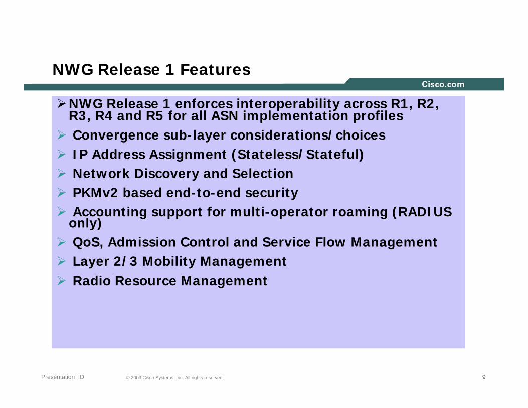
NWG Release 1 enforces interoperability across R1, R2, R3, R4 and R5 for all ASN implementation profilesConvergence sub-layer considerations/choicesIP Address Assignment (Stateless/Stateful)Network Discovery and SelectionPKMv2 based end-to-end security Accounting support for multi-operator roaming (RADIUS
only)QoS, Admission Control and Service Flow ManagementLayer 2/3 Mobility ManagementRadio Resource Management

101010© 2003 Cisco Systems, Inc. All rights reserved.Presentation_ID
.
Implementation Scenarios
.
BSC
BTS
BTS
ASN Scenario 1 – Decomposed BS
MS
ASN GW
Ry
BS1ASN GW
ASN Scenario 2 – BS and ASN GW
Internet
Visited CSN - IP Core
Home CSN - IP Core
R1
R2
R3
R4
R5
Rx
BS2
R6
111111© 2003 Cisco Systems, Inc. All rights reserved.Presentation_ID
Access Scenarios
.
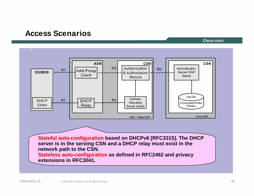
Stateful auto-configuration based on DHCPv6 [RFC3315]. The DHCP server is in the serving CSN and a DHCP relay must exist in the network path to the CSN. Stateless auto-configuration as defined in RFC2462 and privacy extensions in RFC3041.

121212© 2003 Cisco Systems, Inc. All rights reserved.Presentation_ID
Usage Modes
.
Fixed Access / Nomadicity(e.g. DSL Overlay, Greenfield)
Portability / Simple Mobility(e.g. Greenfield, DSL Overlay, 3G Overlay)
Full Mobility(e.g. Greenfield, 3G Overlay)
Usage Modes: Representative of the types of profiles the WiMAX Forum may develop – to guide implementations and multi-vendor interoperability
WiMAX architecture is designed to support evolution path from fixed to nomadic to portability with simple mobility and eventually to full mobilitydeployment with E2E QoS and Securitysupport

131313© 2003 Cisco Systems, Inc. All rights reserved.Presentation_ID
Quality of Service (QoS)
IEEE QoS FrameworkDeals with radio link (802.16) QoSConnection-oriented serviceFive QoS classes are defined- UGS: Unsolicited Grant Service- rtPS: real-time Polling Service- ertPS: enhanced real-time Polling Service- nrtPS: non-real-time Polling Service- BE: Best-Effort
Provisioned QoS profile for permitted flows per subscriberAdmission policies for new service flows
NWG QoS FrameworkExtends the 802.16 QoS framework to NWG NRMDeals with WiMax QoS only (see next slide)QoS control entities are placed either in the BS or ASN GW

141414© 2003 Cisco Systems, Inc. All rights reserved.Presentation_ID
QoS Framework
MS
Admission Control
SFM
LPFLocal Policy Data
ASN
QoS/PolicyData
Home NSP
R3/R5
R1
LocalResources Info
SFA
AF
SFM – Service Flow ManagementSFA – Service Flow AuthorizationAF – Application FunctionPF – Policy FunctionLPF – Local Policy Function
(1) AF => PF
(2) PF => SFA
(3) SFA => SFM
PF
Note – The SFA, after successful user authentication, must update its location with the PF.
151515© 2003 Cisco Systems, Inc. All rights reserved.Presentation_ID
QoS Models in Release 1
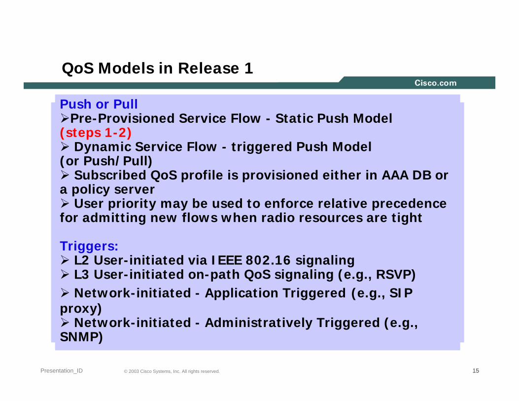
Push or Pull Pre-Provisioned Service Flow - Static Push Model
(steps 1-2)Dynamic Service Flow - triggered Push Model
(or Push/Pull)Subscribed QoS profile is provisioned either in AAA DB or
a policy serverUser priority may be used to enforce relative precedence
for admitting new flows when radio resources are tight
Triggers:L2 User-initiated via IEEE 802.16 signalingL3 User-initiated on-path QoS signaling (e.g., RSVP)Network-initiated - Application Triggered (e.g., SIP
proxy)Network-initiated - Administratively Triggered (e.g.,
SNMP)
161616© 2003 Cisco Systems, Inc. All rights reserved.Presentation_ID
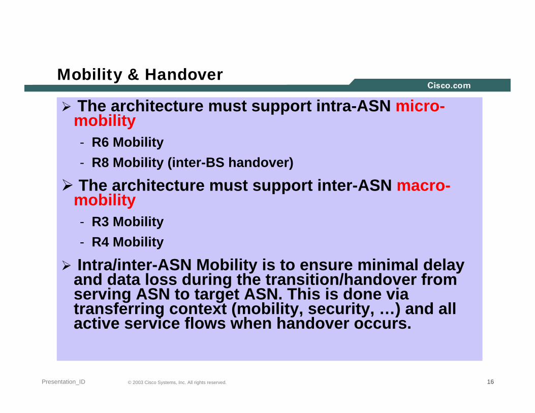
Mobility & Handover
The architecture must support intra-ASN micro-mobility- R6 Mobility- R8 Mobility (inter-BS handover)
The architecture must support inter-ASN macro-mobility- R3 Mobility- R4 Mobility
Intra/inter-ASN Mobility is to ensure minimal delay and data loss during the transition/handover from serving ASN to target ASN. This is done via transferring context (mobility, security, …) and all active service flows when handover occurs.
171717© 2003 Cisco Systems, Inc. All rights reserved.Presentation_ID
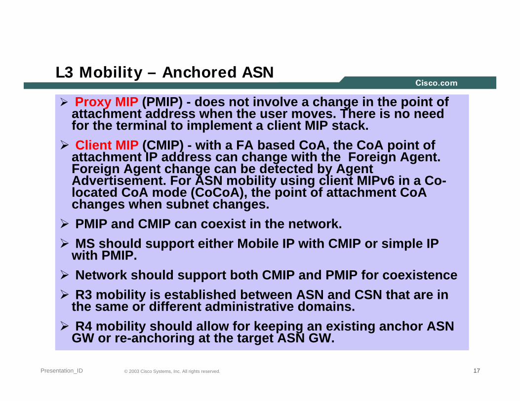
L3 Mobility – Anchored ASN
Proxy MIP (PMIP) - does not involve a change in the point of attachment address when the user moves. There is no need for the terminal to implement a client MIP stack.Client MIP (CMIP) - with a FA based CoA, the CoA point of
attachment IP address can change with the Foreign Agent. Foreign Agent change can be detected by Agent Advertisement. For ASN mobility using client MIPv6 in a Co-located CoA mode (CoCoA), the point of attachment CoA changes when subnet changes. PMIP and CMIP can coexist in the network.MS should support either Mobile IP with CMIP or simple IP
with PMIP.Network should support both CMIP and PMIP for coexistenceR3 mobility is established between ASN and CSN that are in
the same or different administrative domains. R4 mobility should allow for keeping an existing anchor ASN
GW or re-anchoring at the target ASN GW.
181818© 2003 Cisco Systems, Inc. All rights reserved.Presentation_ID
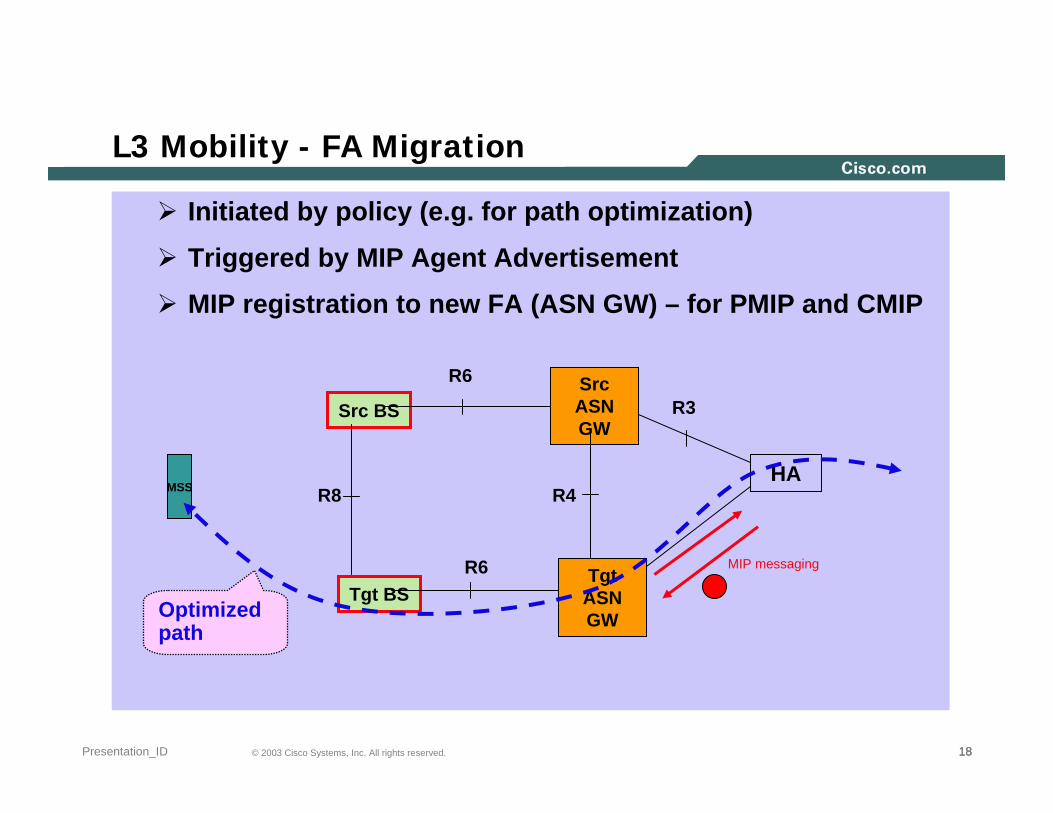
L3 Mobility - FA Migration
Initiated by policy (e.g. for path optimization)
Triggered by MIP Agent Advertisement
MIP registration to new FA (ASN GW) – for PMIP and CMIP
Src BS
Tgt BS
Src ASN GW
R6
Tgt ASN GW
R4
R6
MSS R8
MIP messaging
HA
R3
Optimized path

191919© 2003 Cisco Systems, Inc. All rights reserved.Presentation_ID
R6 Mobility
R6 mobility should take into account different level of Data Path granularities: per-flow, user, and per-BS Data Paths. The Data Path is identified via the classification operation based on a set of classification criteria such as MS IP address.

202020© 2003 Cisco Systems, Inc. All rights reserved.Presentation_ID
Security
WiMAX architecture must comply with the security and trust architecturedefined in the IEEE 802.16 specification and IETF EAP RFCs.Authenticator is anchored during HO (e.g., in the ASN GW)Session is anchored at the first GW through which the MS connects to
the networkHA and Anchor GW have trust relationship with Home AAA
Anchor GW and HA are in different administrative domainsTrust relationship needs to be set up before signallingHome AAA distributes keys to Authenticator and HA
Authenticator distributes AKs to the BSsHA has to authorize setup of forwarding path for MS to Anchor GWSignaling between HA and Anchor GW needs to be secureEAP packets carried between the EAP Relay (BS) and the Authenticator to populate channel binding attributes in the Authenticator
ASN is treated as a single NAS

212121© 2003 Cisco Systems, Inc. All rights reserved.Presentation_ID
What’s Next?
NWG Release 1 ScheduleStage 2 is near completionStage 3 just started (Oct. 2005)
Release 2 (tentative) ScheduleStage 1 2Q06 Stage 2&3 4Q06New Features- Legal Intercept- VoIP (full support)- IPv6 Mobility- IMS- BCMCS- Other features as requested by SPWG.
Related Documents


![IEEE 802.16: WiMAX Overview, WiMAX · PDF filevs. 3G. The common Misconceptions about WiMAX & 3G CDMA are [5]: 1) Cost . c. ... IEEE 802.16: WiMAX Overview, WiMAX Architecture . Mojtaba](https://static.cupdf.com/doc/110x72/5a752f217f8b9ad22a8c6f07/ieee-80216-wimax-overview-wimax-architecture-vs-3g-the-common-misconceptions.jpg)