PX3-3000/4000/5000 Series User Guide Xerus ™ Firmware v3.5.0 Copyright © 2019 Raritan, Inc. PX3-1F-v3.5.0-E January 2019 255-80-0035-00

Welcome message from author
This document is posted to help you gain knowledge. Please leave a comment to let me know what you think about it! Share it to your friends and learn new things together.
Transcript

PX3-3000/4000/5000 Series User Guide
Xerus™ Firmware v3.5.0
Copyright © 2019 Raritan, Inc. PX3-1F-v3.5.0-E January 2019 255-80-0035-00

WARNING! Read and understand all sections in this guide before installing or operating this product.
WARNING! Connect this product to an AC power source whose voltage is within the range specified on the product's nameplate. Operating this product outside the nameplate voltage range may result in electric shock, fire, personal injury and death.
WARNING! Connect this product to an AC power source that is current limited by a suitably rated fuse or circuit breaker in accordance with national and local electrical codes. Operating this product without proper current limiting may result in electric shock, fire, personal injury and death.
WARNING! Connect this product to a protective earth ground. Never use a "ground lift adaptor" between the product's plug and the wall receptacle. Failure to connect to a protective earth ground may result in electric shock, fire, personal injury and death.
WARNING! This product contains no user serviceable parts. Do not open, alter or disassemble this product. All servicing must be performed by qualified personnel. Disconnect power before servicing this product. Failure to comply with this warning may result in electric shock, personal injury and death.
WARNING! Use this product in a dry location. Failure to use this product in a dry location may result in electric shock, personal injury and death.
WARNING! Do not rely on this product's receptacle lamps, receptacle relay switches or any other receptacle power on/off indicator to determine whether power is being supplied to a receptacle. Unplug a device connected to this product before performing repair, maintenance or service on the device. Failure to unplug a device before servicing it may result in electric shock, fire, personal injury and death.
WARNING! Only use this product to power information technology equipment that has a UL/IEC 60950-1 or equivalent rating. Attempting to power non-rated devices may result in electric shock, fire, personal injury and death.
WARNING! Do not use a Raritan product containing outlet relays to power large inductive loads such as motors or compressors. Attempting to power a large inductive load may result in damage to the relay.
WARNING! Do not use this product to power critical patient care equipment, fire or smoke alarm systems. Use of this product to power such equipment may result in personal injury and death.
WARNING! If this product is a model that requires assembly of its line cord or plug, all such assembly must be performed by a licensed electrician and the line cord or plugs used must be suitably rated based on the product's nameplate ratings and national and local electrical codes. Assembly by unlicensed electricians or failure to use suitably rated line cords or plugs may result in electric shock, fire, personal injury or death.
WARNING! This product contains a chemical known to the State of California to cause cancer, birth defects, or other reproductive harm.
Safety Guidelines

1. Installation of this product should only be performed by a person who has knowledge and experience with electric power.
2. Make sure the line cord is disconnected from power before physically mounting or moving the location of this product.
3. This product is designed to be used within an electronic equipment rack. The metal case of this product is electrically bonded to the line cord ground wire. A threaded grounding point on the case may be used as an additional means of protectively grounding this product and the rack.
4. Examine the branch circuit receptacle that will supply electric power to this product. Make sure the receptacle’s power lines, neutral and protective earth ground pins are wired correctly and are the correct voltage and phase. Make sure the branch circuit receptacle is protected by a suitably rated fuse or circuit breaker.
5. If the product is a model that contains receptacles that can be switched on/off, electric power may still be present at a receptacle even when it is switched off.
Tip 1: The outlet (socket) shall be installed near the equipment and shall be easily accessible.
Tip 2: For detailed information on any Raritan PDU's overcurrent protectors' design, refer to that model's product specification on Raritan website's PDU Product Selector page https://www.raritan.com/product-selector.
Safety Instructions

This document contains proprietary information that is protected by copyright. All rights reserved. No part of this document may be photocopied, reproduced, or translated into another language without express prior written consent of Raritan, Inc.
© Copyright 2019 Raritan, Inc. All third-party software and hardware mentioned in this document are registered trademarks or trademarks of and are the property of their respective holders.
FreeType Project Copyright Notice
Portions of this software are copyright © 2015 The FreeType Project (www.freetype.org). All rights reserved.
FCC Information
This equipment has been tested and found to comply with the limits for a Class A digital device, pursuant to Part 15 of the FCC Rules. These limits are designed to provide reasonable protection against harmful interference in a commercial installation. This equipment generates, uses, and can radiate radio frequency energy and if not installed and used in accordance with the instructions, may cause harmful interference to radio communications. Operation of this equipment in a residential environment may cause harmful interference.
VCCI Information (Japan)
Raritan is not responsible for damage to this product resulting from accident, disaster, misuse, abuse, non-Raritan modification of the product, or other events outside of Raritan's reasonable control or not arising under normal operating conditions.
If a power cable is included with this product, it must be used exclusively for this product.

vi
Contents
Safety Guidelines ii
Safety Instructions iii
Applicable Models xviii
What's New in the PX3 User Guide xx
Chapter 1 Introduction 1
Product Models................................................................................................................................. 1 Package Contents............................................................................................................................. 1
Zero U Products ..................................................................................................................... 2 1U Products............................................................................................................................ 2 2U Products............................................................................................................................ 2
APIPA and Link-Local Addressing ................................................................................................... 2 Before You Begin .............................................................................................................................. 3
Unpacking the Product and Components.............................................................................. 3 Preparing the Installation Site............................................................................................... 4 Checking the Branch Circuit Rating ...................................................................................... 4 Filling Out the Equipment Setup Worksheet ......................................................................... 4
Chapter 2 Rackmount, Inlet and Outlet Connections 5
Circuit Breaker Orientation Limitation ............................................................................................ 5 Rack-Mounting the PDU................................................................................................................... 5
Rackmount Safety Guidelines................................................................................................ 5 Mounting Zero U Models Using L-Brackets .......................................................................... 6 Mounting Zero U Models Using Button Mount ...................................................................... 7 Mounting Zero U Models Using Claw-Foot Brackets............................................................ 8 Mounting Zero U Models Using Two Rear Buttons ............................................................. 10 Mounting 1U or 2U Models .................................................................................................. 11
Connecting a PX3 Locking Line Cord ............................................................................................. 12 Disconnecting a PX3 Locking Line Cord.............................................................................. 13
Installing Cable Retention Clips on the Inlet (Optional) ................................................................ 14 Installing Cable Retention Clips on Outlets (Optional) .................................................................. 15 Locking Outlets and Cords ............................................................................................................. 16
SecureLock™ Outlets and Cords......................................................................................... 16
Contents
vii
Button-Type Locking Outlets ............................................................................................... 18
Chapter 3 Initial Installation and Configuration 19
Connecting the PDU to a Power Source ........................................................................................ 19 Connecting the PX3 to Your Network............................................................................................. 19
USB Wireless LAN Adapters................................................................................................ 21 Supported Wireless LAN Configuration .............................................................................. 21 Dual Ethernet Connection.................................................................................................... 21
Configuring the PX3........................................................................................................................ 22 Connecting a Mobile Device to PX3 ..................................................................................... 23 Connecting the PX3 to a Computer...................................................................................... 28
Bulk Configuration Methods .......................................................................................................... 31 Cascading Multiple PX3 Devices for Sharing Ethernet Connectivity............................................. 32
Cascading All Devices via USB ............................................................................................ 33 Extended Cascading with PX3 Devices ................................................................................ 36 Restrictions of Port-Forwarding Connections .................................................................... 39
Power-Sharing Restrictions and Connection ................................................................................ 41 Making a Power-Sharing Connection.................................................................................. 42 Power-Sharing Configurations and Restrictions ................................................................ 43 Supported Sensor Configurations for Power Sharing......................................................... 44
Chapter 4 Connecting External Equipment (Optional) 46
Connecting Raritan Environmental Sensor Packages .................................................................. 46 Identifying the Sensor Port .................................................................................................. 46 DX2 Sensor Packages .......................................................................................................... 47 DX Sensor Packages ............................................................................................................ 48 DPX3 Sensor Packages........................................................................................................ 50 DPX2 Sensor Packages........................................................................................................ 51 DPX Sensor Packages.......................................................................................................... 54 Using an Optional DPX3-ENVHUB4 Sensor Hub ................................................................. 59 Mixing Diverse Sensor Types............................................................................................... 60
Connecting Asset Management Strips........................................................................................... 65 Combining Regular Asset Strips ......................................................................................... 65 Introduction to Asset Tags................................................................................................... 67 Connecting Regular Asset Strips to PX3 ............................................................................. 68 Connecting Blade Extension Strips ..................................................................................... 69 Connecting Composite Asset Strips (AMS-Mx-Z)................................................................ 72
Contents
viii
Connecting a Logitech Webcam..................................................................................................... 75 Connecting a GSM Modem ............................................................................................................. 75 Connecting an Analog Modem ....................................................................................................... 76 Connecting an External Beeper ..................................................................................................... 77 Connecting a Schroff LHX/SHX Heat Exchanger ........................................................................... 77
Chapter 5 Introduction to PDU Components 78
Panel Components ......................................................................................................................... 78 Inlet ...................................................................................................................................... 78 Outlets .................................................................................................................................. 79 Connection Ports.................................................................................................................. 81 Dot-Matrix LCD Display ....................................................................................................... 84 Reset Button ...................................................................................................................... 124
Circuit Breakers ........................................................................................................................... 125 Resetting the Button-Type Circuit Breaker....................................................................... 125 Resetting the Handle-Type Circuit Breaker...................................................................... 126
Fuse .............................................................................................................................................. 127 Fuse Replacement on Zero U Models ............................................................................... 127 Fuse Replacement on 1U Models ...................................................................................... 128
Beeper .......................................................................................................................................... 130 Replaceable Controller ................................................................................................................ 130 Threaded Grounding Point ........................................................................................................... 132
Chapter 6 Using the Web Interface 133
Supported Web Browsers ............................................................................................................ 133 Login, Logout and Password Change........................................................................................... 133
Login................................................................................................................................... 133 Changing Your Password................................................................................................... 135 Remembering User Names and Passwords ..................................................................... 137 Logout ................................................................................................................................ 137
Web Interface Overview................................................................................................................ 137 Menu................................................................................................................................... 139 Quick Access to a Specific Page ........................................................................................ 143 Sorting a List ...................................................................................................................... 144
Dashboard .................................................................................................................................... 145 Dashboard - Inlet I1 ........................................................................................................... 147 Dashboard - OCP ............................................................................................................... 149 Dashboard - Alerted Sensors ............................................................................................ 150 Dashboard - Inlet History .................................................................................................. 151 Dashboard - Alarms........................................................................................................... 154
PDU ............................................................................................................................................... 155 Internal Beeper State ........................................................................................................ 159 PX3 Latching Relay Behavior............................................................................................. 160 Options for Outlet State on Startup ................................................................................... 160

Contents
ix
Initialization Delay Use Cases............................................................................................ 161 Inrush Current and Inrush Guard Delay............................................................................ 161 Time Units .......................................................................................................................... 161 Setting Thresholds for Total Active Energy or Power ....................................................... 162 +12V Power Supply Sensor ................................................................................................ 163
Inlet ............................................................................................................................................... 164 Configuring a Multi-Inlet Model......................................................................................... 166
Outlets .......................................................................................................................................... 168 Available Data of the Outlets Overview Page .................................................................... 172 Bulk Configuration for Outlet Thresholds ......................................................................... 173 Setting Outlet Power-On Sequence and Delay.................................................................. 174 Setting Non-Critical Outlets .............................................................................................. 175 Load Shedding Mode.......................................................................................................... 176 Individual Outlet Pages ...................................................................................................... 179
Outlet Groups................................................................................................................................ 186 Creating an Outlet Group................................................................................................... 187 Outlet Group Power Control .............................................................................................. 188 Resetting a Group's Active Energy .................................................................................... 191 Modifying an Outlet Group ................................................................................................. 193 Deleting an Outlet Group ................................................................................................... 196 Viewing More Information.................................................................................................. 197
OCPs ............................................................................................................................................. 199 Individual OCP Pages ......................................................................................................... 202 Possible OCP-Tripped Root Cause .................................................................................... 206
Peripherals ................................................................................................................................... 207 Yellow- or Red-Highlighted Sensors................................................................................. 214 Managed vs Unmanaged Sensors/Actuators .................................................................... 215 Sensor/Actuator States...................................................................................................... 216 Finding the Sensor's Serial Number ................................................................................. 218 Identifying the Sensor Position and Channel .................................................................... 219 How the Automatic Management Function Works............................................................ 220 Managing One Sensor or Actuator .................................................................................... 221 Individual Sensor/Actuator Pages ..................................................................................... 222 Z Coordinate Format.......................................................................................................... 228
Feature Port ................................................................................................................................. 229 Asset Strip.......................................................................................................................... 230 External Beeper ................................................................................................................. 238 Schroff LHX/SHX ................................................................................................................ 238 Power CIM.......................................................................................................................... 243
User Management ........................................................................................................................ 243 Creating Users ................................................................................................................... 244 Editing or Deleting Users................................................................................................... 248 Creating Roles.................................................................................................................... 250 Editing or Deleting Roles ................................................................................................... 252 Setting Your Preferred Measurement Units ..................................................................... 253 Setting Default Measurement Units .................................................................................. 253
Contents
x
Device Settings ............................................................................................................................. 254 Configuring Network Settings ........................................................................................... 256 Configuring Network Services........................................................................................... 278 Configuring Security Settings............................................................................................ 286 Setting the Date and Time ................................................................................................. 310 Event Rules and Actions .................................................................................................... 314 Setting Data Logging.......................................................................................................... 375 Configuring Data Push Settings ........................................................................................ 376 Monitoring Server Accessibility ......................................................................................... 384 Front Panel Settings .......................................................................................................... 393 Configuring the Serial Port................................................................................................ 394 Lua Scripts ......................................................................................................................... 396 Miscellaneous .................................................................................................................... 402
Maintenance ................................................................................................................................. 403 Device Information............................................................................................................. 405 Viewing Connected Users .................................................................................................. 410 Viewing or Clearing the Local Event Log........................................................................... 412 Updating the PX3 Firmware............................................................................................... 413 Viewing Firmware Update History ..................................................................................... 417 Bulk Configuration ............................................................................................................. 418 Backup and Restore of Device Settings............................................................................. 425 Network Diagnostics.......................................................................................................... 426 Downloading Diagnostic Information ................................................................................ 428 Hardware Issue Detection ................................................................................................. 428 Rebooting the PX3.............................................................................................................. 429 Resetting All Settings to Factory Defaults ........................................................................ 430 Retrieving Software Packages Information....................................................................... 431
Webcam Management.................................................................................................................. 431 Configuring Webcams and Viewing Live Images............................................................... 433 Sending Links to Snapshots or Videos .............................................................................. 436 Viewing and Managing Locally-Saved Snapshots ............................................................. 439 Changing Storage Settings ................................................................................................ 441
SmartLock and Card Reader........................................................................................................ 444 SmartLock.......................................................................................................................... 446 Card Readers ..................................................................................................................... 451
Chapter 7 Using SNMP 453
Enabling and Configuring SNMP.................................................................................................. 453 SNMPv2c Notifications....................................................................................................... 454 SNMPv3 Notifications ........................................................................................................ 455
Downloading SNMP MIB .............................................................................................................. 458 SNMP Gets and Sets..................................................................................................................... 458
The PX3 MIB ....................................................................................................................... 459 Retrieving Energy Usage ................................................................................................... 461 A Note about Enabling Thresholds.................................................................................... 461
Contents
xi
Chapter 8 Using the Command Line Interface 462
About the Interface....................................................................................................................... 462 Logging in to CLI........................................................................................................................... 463
With HyperTerminal........................................................................................................... 463 With SSH or Telnet............................................................................................................. 464 With an Analog Modem ...................................................................................................... 465 Different CLI Modes and Prompts ..................................................................................... 465 Closing a Local Connection ............................................................................................... 466
The ? Command for Showing Available Commands.................................................................... 466 Querying Available Parameters for a Command......................................................................... 467 Showing Information .................................................................................................................... 467
Network Configuration....................................................................................................... 468 PDU Configuration ............................................................................................................. 472 Outlet Information.............................................................................................................. 472 Outlet Group Information................................................................................................... 473 Inlet Information ................................................................................................................ 474 Overcurrent Protector Information ................................................................................... 475 Date and Time Settings...................................................................................................... 475 Default Measurement Units............................................................................................... 476 Environmental Sensor Information ................................................................................... 476 Environmental Sensor Package Information .................................................................... 478 Actuator Information.......................................................................................................... 478 Outlet Sensor Threshold Information................................................................................ 479 Outlet Pole Sensor Threshold Information ....................................................................... 480 Outlet Group Threshold Information ................................................................................. 481 Inlet Sensor Threshold Information .................................................................................. 482 Inlet Pole Sensor Threshold Information .......................................................................... 484 Overcurrent Protector Sensor Threshold Information ..................................................... 485 Environmental Sensor Threshold Information.................................................................. 486 Environmental Sensor Default Thresholds ....................................................................... 487 Security Settings ................................................................................................................ 488 Authentication Settings...................................................................................................... 489 Existing User Profiles ........................................................................................................ 490 Existing Roles..................................................................................................................... 491 Load Shedding Settings ..................................................................................................... 491 Serial Port Settings............................................................................................................ 491 EnergyWise Settings .......................................................................................................... 492 Asset Strip Settings ........................................................................................................... 492 Rack Unit Settings of an Asset Strip.................................................................................. 492 Blade Extension Strip Settings .......................................................................................... 493 Event Log............................................................................................................................ 494 Wireless LAN Diagnostic Log ............................................................................................ 495 Server Reachability Information........................................................................................ 495
Contents
xii
Command History .............................................................................................................. 496 Reliability Data ................................................................................................................... 497 Reliability Error Log........................................................................................................... 497 Reliability Hardware Failures............................................................................................ 497 Examples............................................................................................................................ 497
Clearing Information .................................................................................................................... 499 Clearing Event Log............................................................................................................. 499 Clearing WLAN Log............................................................................................................ 500
Configuring the PX3 Device and Network .................................................................................... 500 Entering Configuration Mode............................................................................................. 500 Quitting Configuration Mode.............................................................................................. 501 PDU Configuration Commands.......................................................................................... 501 Network Configuration Commands................................................................................... 509 Time Configuration Commands......................................................................................... 533 Checking the Accessibility of NTP Servers ....................................................................... 537 Security Configuration Commands.................................................................................... 537 Outlet Configuration Commands....................................................................................... 557 Outlet Group Configuration Commands ............................................................................ 559 Inlet Configuration Commands.......................................................................................... 561 Overcurrent Protector Configuration Commands............................................................. 563 User Configuration Commands ......................................................................................... 563 Role Configuration Commands.......................................................................................... 575 Authentication Commands ................................................................................................ 580 Environmental Sensor Configuration Commands ............................................................ 592 Configuring Environmental Sensors' Default Thresholds ................................................ 596 Sensor Threshold Configuration Commands.................................................................... 598 Actuator Configuration Commands................................................................................... 611 Server Reachability Configuration Commands ................................................................. 612 EnergyWise Configuration Commands.............................................................................. 616 Asset Management Commands......................................................................................... 617 Serial Port Configuration Commands ............................................................................... 623 Multi-Command Syntax ..................................................................................................... 625
Load Shedding Configuration Commands ................................................................................... 627 Enabling or Disabling Load Shedding................................................................................ 627
Power Control Operations............................................................................................................ 628 Turning On the Outlet(s) .................................................................................................... 628 Turning Off the Outlet(s) .................................................................................................... 629 Power Cycling the Outlet(s) ............................................................................................... 630 Canceling the Power-On Process...................................................................................... 631 Example - Power Cycling Specific Outlets ........................................................................ 631
Actuator Control Operations ........................................................................................................ 631 Switching On an Actuator................................................................................................... 632 Switching Off an Actuator .................................................................................................. 632 Example - Turning On a Specific Actuator ........................................................................ 633
Contents
xiii
Unblocking a User ........................................................................................................................ 633 Resetting the PX3 ......................................................................................................................... 633
Restarting the PDU ............................................................................................................ 633 Resetting Active Energy Readings..................................................................................... 634 Resetting to Factory Defaults ............................................................................................ 635
Network Troubleshooting............................................................................................................. 635 Entering Diagnostic Mode.................................................................................................. 635 Quitting Diagnostic Mode................................................................................................... 636 Diagnostic Commands....................................................................................................... 636
Retrieving Previous Commands................................................................................................... 638 Automatically Completing a Command ....................................................................................... 638 Logging out of CLI......................................................................................................................... 639
Chapter 9 Using SCP Commands 640
Firmware Update via SCP ............................................................................................................ 640 Bulk Configuration via SCP .......................................................................................................... 641 Backup and Restore via SCP........................................................................................................ 642 Downloading Diagnostic Data via SCP ......................................................................................... 643 Uploading or Downloading Raw Configuration Data ................................................................... 645
Keys that Cannot Be Uploaded .......................................................................................... 649
Chapter 10 In-Line Monitors 650
Overview........................................................................................................................................ 650 Safety Instructions........................................................................................................................ 650 Flexible Cord Installation Instructions ........................................................................................ 651
Flexible Cord Selection...................................................................................................... 652 Plug Selection .................................................................................................................... 652 Receptacle Selection ......................................................................................................... 652 Derating a Raritan Product................................................................................................ 652 Wiring of 3-Phase In-Line Monitors .................................................................................. 653 In-Line Monitor Unused Channels..................................................................................... 654 Step by Step Flexible Cord Installation ............................................................................. 654
In-Line Monitor's Web Interface .................................................................................................. 659 Dashboard Page................................................................................................................. 659 Inlets/Outlets Page ............................................................................................................ 664
Contents
xiv
Appendix A Specifications 667
Maximum Ambient Operating Temperature................................................................................ 667 Serial RS-232 "RJ-45" Port Pinouts............................................................................................. 667 Sensor RJ-45 Port Pinouts........................................................................................................... 667 Feature RJ-45 Port Pinouts ......................................................................................................... 668 Expansion RJ-45 Port Pinouts ..................................................................................................... 669
Appendix B Equipment Setup Worksheet 670
Appendix C Configuration or Firmware Upgrade with a USB Drive 673
Device Configuration/Upgrade Procedure................................................................................... 673 System and USB Requirements................................................................................................... 674 Configuration Files ....................................................................................................................... 675
fwupdate.cfg....................................................................................................................... 675 config.txt............................................................................................................................. 680 devices.csv ......................................................................................................................... 682 Creating Configuration Files via Mass Deployment Utility ............................................... 683 Data Encryption in 'config.txt'............................................................................................ 684
Firmware Upgrade via USB.......................................................................................................... 686
Appendix D Bulk Configuration or Firmware Upgrade via DHCP/TFTP 688
Bulk Configuration/Upgrade Procedure...................................................................................... 688 TFTP Requirements...................................................................................................................... 689 DHCP IPv4 Configuration in Windows.......................................................................................... 690 DHCP IPv6 Configuration in Windows.......................................................................................... 700 DHCP IPv4 Configuration in Linux................................................................................................ 707 DHCP IPv6 Configuration in Linux................................................................................................ 709
Appendix E Raw Configuration Upload and Download 711
Downloading Raw Configuration.................................................................................................. 711 Download via Web Browsers ............................................................................................. 711 Download via Curl .............................................................................................................. 712
Uploading Raw Configuration....................................................................................................... 713 Upload via Curl................................................................................................................... 714 Curl Upload Return Codes................................................................................................. 715

Contents
xv
Appendix F Resetting to Factory Defaults 717
Using the Reset Button ................................................................................................................ 717 Using the CLI Command .............................................................................................................. 718
Appendix G PX3 Models with Residual Current Monitoring 720
RCM Current Sensor .................................................................................................................... 720 RCM State Sensor......................................................................................................................... 721 Compliance with IEC 62020.......................................................................................................... 722 RCM Self-Test............................................................................................................................... 723 Web Interface Operations for RCM .............................................................................................. 723
Checking RCM State and Current...................................................................................... 724 Setting RCM Current Thresholds ...................................................................................... 726 Scheduling RCM Self-Test................................................................................................. 728 Disabling or Enabling Front Panel RCM Self-Test............................................................ 728 Setting RCM DC Current Thresholds................................................................................. 729
Front Panel Operations for RCM.................................................................................................. 730 LCD Message for RCM Critical State................................................................................. 730 Checking RCM States and Current.................................................................................... 731 Running RCM Self-Test ..................................................................................................... 732
RCM SNMP Operations ................................................................................................................ 734 RCM Trap............................................................................................................................ 734 RCM Residual Current and State Objects ......................................................................... 734 Setting RCM Thresholds .................................................................................................... 734 Running RCM Self-Test ..................................................................................................... 734
CLI Operations for RCM................................................................................................................ 735 Showing Residual Current Monitoring Information .......................................................... 735 Setting RCM Current Thresholds ...................................................................................... 735 Setting Front Panel RCM Self-Test ................................................................................... 737 Running RCM Self-Test ..................................................................................................... 737 Degaussing RCM Type B Sensors...................................................................................... 737
Appendix H Old Generations of PX3 Models 739
PX3 'Phase II' Front Panel Display............................................................................................... 739 PX3 'Phase I' Front Panel Display ................................................................................................ 740
Overview of the LCD Display .............................................................................................. 740 Control Buttons.................................................................................................................. 741 Operating the LCD Display................................................................................................. 742
Contents
xvi
Serial RS-232 "DB9" Port Pinouts ............................................................................................... 757
Appendix I LDAP Configuration Illustration 759
Step A. Determine User Accounts and Roles .............................................................................. 759 Step B. Configure User Groups on the AD Server ....................................................................... 760 Step C. Configure LDAP Authentication on the PX3 .................................................................... 760 Step D. Configure Roles on the PX3............................................................................................. 762
Appendix J Updating the LDAP Schema 765
Returning User Group Information .............................................................................................. 765 From LDAP/LDAPS ............................................................................................................ 765 From Microsoft Active Directory........................................................................................ 765
Setting the Registry to Permit Write Operations to the Schema................................................. 766 Creating a New Attribute.............................................................................................................. 766 Adding Attributes to the Class ..................................................................................................... 767 Updating the Schema Cache ........................................................................................................ 769 Editing rciusergroup Attributes for User Members .................................................................... 769
Appendix K RADIUS Configuration Illustration 772
Standard Attributes ...................................................................................................................... 772 NPS Standard Attribute Illustration .................................................................................. 772 FreeRADIUS Standard Attribute Illustration..................................................................... 789
Vendor-Specific Attributes ........................................................................................................... 790 NPS VSA Illustration .......................................................................................................... 790 FreeRADIUS VSA Illustration............................................................................................. 801
AD-Related Configuration ............................................................................................................ 802
Appendix L Additional PX3 Information 806
RJ45-to-DB9 Cable Requirements for Modem Connections ...................................................... 806 Reserving IP Addresses in DHCP Servers ................................................................................... 807
Reserving IP in Windows.................................................................................................... 807 Reserving IP in Linux ......................................................................................................... 809
Sensor Threshold Settings........................................................................................................... 810 Thresholds and Sensor States........................................................................................... 811 "To Assert" and Assertion Timeout ................................................................................... 813 "To De-assert" and Deassertion Hysteresis ..................................................................... 815
Contents
xvii
Default Voltage and Current Thresholds ..................................................................................... 817 Altitude Correction Factors.......................................................................................................... 819 Unbalanced Current Calculation.................................................................................................. 820 Data for BTU Calculation.............................................................................................................. 821 Ways to Probe Existing User Profiles .......................................................................................... 821 Raritan Training Website.............................................................................................................. 822 Role of a DNS Server.................................................................................................................... 822 Cascading Troubleshooting.......................................................................................................... 822
Possible Root Causes ........................................................................................................ 823 Slave Device Events in the Log .......................................................................................... 825 The Ping Tool...................................................................................................................... 826
Installing the USB-to-Serial Driver (Optional)............................................................................. 826 Initial Network Configuration via CLI........................................................................................... 828 Device-Specific Settings............................................................................................................... 833 TLS Certificate Chain.................................................................................................................... 833
What is a Certificate Chain ................................................................................................ 833 Illustration - GMAIL SMTP Certificate Chain..................................................................... 837
Browsing through the Online Help............................................................................................... 840
Appendix M Integration 842
Dominion KX II / III Configuration................................................................................................. 842 Configuring Rack PDU Targets.......................................................................................... 842 Turning Outlets On/Off and Cycling Power........................................................................ 846
Dominion KSX II, SX or SX II Configuration .................................................................................. 847 Dominion KSX II.................................................................................................................. 847 Dominion SX and SX II ........................................................................................................ 848
Power IQ Configuration ................................................................................................................ 852 dcTrack ......................................................................................................................................... 852
dcTrack Overview............................................................................................................... 853 Asset Management Strips and dcTrack............................................................................. 854
Index 855
xviii
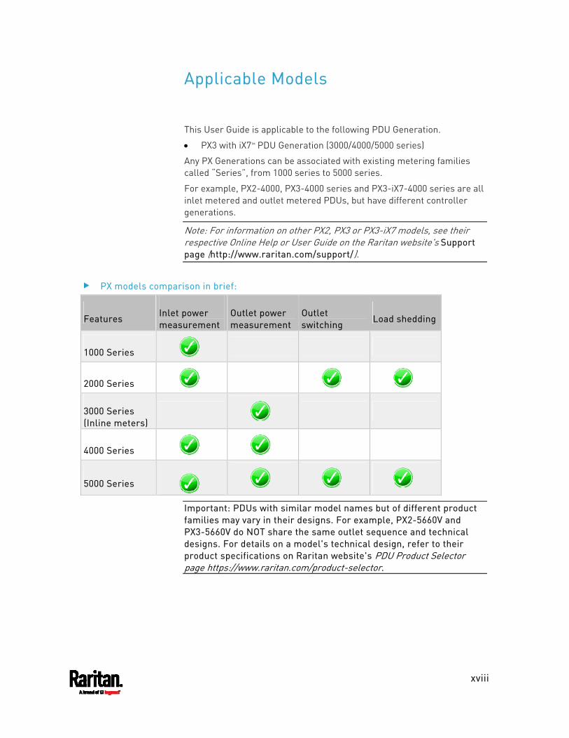
This User Guide is applicable to the following PDU Generation.
PX3 with iX7™ PDU Generation (3000/4000/5000 series)
Any PX Generations can be associated with existing metering families called “Series”, from 1000 series to 5000 series.
For example, PX2-4000, PX3-4000 series and PX3-iX7-4000 series are all inlet metered and outlet metered PDUs, but have different controller generations.
Note: For information on other PX2, PX3 or PX3-iX7 models, see their respective Online Help or User Guide on the Raritan website's Support page (http://www.raritan.com/support/).
PX models comparison in brief:
Features Inlet power measurement
Outlet power measurement
Outlet switching
Load shedding
1000 Series
2000 Series
3000 Series (Inline meters)
4000 Series
5000 Series
Important: PDUs with similar model names but of different product families may vary in their designs. For example, PX2-5660V and PX3-5660V do NOT share the same outlet sequence and technical designs. For details on a model's technical design, refer to their product specifications on Raritan website's PDU Product Selector page https://www.raritan.com/product-selector.
Applicable Models
Applicable Models
xix
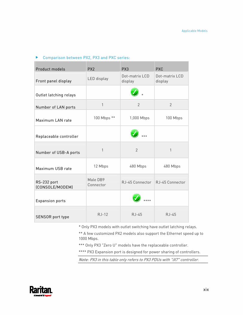
Comparison between PX2, PX3 and PXC series:
Product models PX2 PX3 PXC
Front panel display LED display Dot-matrix LCD display
Dot-matrix LCD display
Outlet latching relays *
Number of LAN ports 1 2 2
Maximum LAN rate 100 Mbps ** 1,000 Mbps 100 Mbps
Replaceable controller ***
Number of USB-A ports 1 2 1
Maximum USB rate 12 Mbps 480 Mbps 480 Mbps
RS-232 port (CONSOLE/MODEM)
Male DB9 Connector
RJ-45 Connector RJ-45 Connector
Expansion ports ****
SENSOR port type RJ-12 RJ-45 RJ-45
* Only PX3 models with outlet switching have outlet latching relays.
** A few customized PX2 models also support the Ethernet speed up to 1000 Mbps.
*** Only PX3 "Zero U" models have the replaceable controller.
**** PX3 Expansion port is designed for power sharing of controllers.
Note: PX3 in this table only refers to PX3 PDUs with "iX7" controller.
xx
Important: If your PX3 is running any firmware version older than 3.3.0, you must upgrade it to 3.3.x or 3.4.x before upgrading it to 3.5.0 or later. See Updating the PX3 Firmware (on page 413).
The following sections have changed or information has been added to the PX3 User Guide based on enhancements and changes to the equipment and/or user documentation.
Applicable Models (on page xviii)
Introduction (on page 1)
Zero U Products (on page 2)
1U Products (on page 2)
2U Products (on page 2)
Connecting the PX3 to Your Network (on page 19)
Supported Wireless LAN Configuration (on page 21)
Dual Ethernet Connection (on page 21)
Saving User Credentials for PDView's Automatic Login (on page 26)
RJ45-to-DB9 Cable Requirements for Computer Connections (on page 30)
Bulk Configuration Methods (on page 31)
Cascading Multiple PX3 Devices for Sharing Ethernet Connectivity (on page 32)
Cascading All Devices via USB (on page 33)
Extended Cascading with PX3 Devices (on page 36)
Power-Sharing Restrictions and Connection (on page 41)
Making a Power-Sharing Connection (on page 42)
Power-Sharing Configurations and Restrictions (on page 43)
Supported Sensor Configurations for Power Sharing (on page 44)
Using an Optional DPX-ENVHUB4 Sensor Hub (on page 56)
Daisy-Chain Limitations of Composite Asset Strips (on page 74)
Connecting a Logitech Webcam (on page 75)
Connecting a GSM Modem (on page 75)
Connecting an Analog Modem (on page 76)
PX3-5000 Series (on page 80)
Zero U Connection Ports (on page 81)
What's New in the PX3 User Guide
What's New in the PX3 User Guide
xxi
Dot-Matrix LCD Display (on page 84)
Automatic and Manual Modes (on page 84)
Control Buttons (on page 85)
Operating the Dot-Matrix LCD Display (on page 86)
Main Menu (on page 87)
Alerts (on page 88)
PDU (on page 91)
Muting the Internal Beeper (on page 94)
Outlet Groups (on page 103)
Showing an Outlet Group's Information (on page 103)
Group's Power Control (on page 105)
Device Info (on page 115)
Manually Changing the Zero U LCD Orientation (on page 121)
Alerts Notice in a Yellow or Red Screen (on page 121)
Reset Button (on page 124)
Threaded Grounding Point (on page 132)
Supported Web Browsers (on page 133)
Login (on page 133)
Web Interface Overview (on page 137)
Menu (on page 139)
Dashboard (on page 145)
Dashboard - Alarms (on page 154)
PDU (on page 155)
+12V Power Supply Sensor (on page 163)
Inlet (on page 164)
Off and Lock Icons for Outlets (on page 178)
Individual Outlet Pages (on page 179)
Outlet Groups (on page 186)
Creating an Outlet Group (on page 187)
Outlet Group Power Control (on page 188)
If Switchable Outlet Groups are Limited (on page 191)
Resetting a Group's Active Energy (on page 191)
Modifying an Outlet Group (on page 193)
Deleting an Outlet Group (on page 196)
Chapter 1: What's New in the PX3 User Guide
xxii
Viewing More Information (on page 197)
Peripherals (on page 207)
Configuring Network Settings (on page 256)
Wired Network Settings (on page 258)
Ethernet Interface Settings (on page 260)
Setting the Cascading Mode (on page 269)
Changing HTTP(S) Settings (on page 280)
Setting the Date and Time (on page 310)
Default Log Messages (on page 321)
Available Actions (on page 336)
Shut down a Server and Control its Power (on page 342)
Send Email (on page 345)
Send SMS Message (on page 348)
Switch Outlet Group (on page 354)
Placeholders for Custom Messages (on page 363)
Configuring Data Push Settings (on page 376)
Data Push Format (on page 378)
Sensor Log (on page 378)
Sensor Descriptors for Inlet Active Power (on page 379)
Log Rows (on page 380)
Asset Management Tag List (on page 381)
Asset Management Log (on page 383)
Monitoring Server Accessibility (on page 384)
Server Status Checking or Power Control (on page 389)
Front Panel Settings (on page 393)
Miscellaneous (on page 402)
Maintenance (on page 403)
Updating the PX3 Firmware (on page 413)
Full Disaster Recovery (on page 417)
Bulk Configuration (on page 418)
Performing Bulk Configuration (on page 422)
Hardware Issue Detection (on page 428)
SmartLock (on page 446)
Door Handle Status and Control (on page 448)
Card Readers (on page 451)
What's New in the PX3 User Guide
xxiii
IP Configuration (on page 468)
IPv4-Only or IPv6-Only Configuration (on page 469)
Network Interface Settings (on page 470)
Outlet Group Information (on page 473)
Outlet Group Threshold Information (on page 481)
Reliability Hardware Failures (on page 497)
Setting the IPv4 Configuration Mode (on page 509)
Setting the IPv4 Preferred Host Name (on page 510)
Setting the IPv4 Address (on page 511)
Setting IPv4 Static Routes (on page 512)
Setting the IPv6 Configuration Mode (on page 513)
Setting the IPv6 Preferred Host Name (on page 514)
Setting the IPv6 Address (on page 515)
Setting IPv6 Static Routes (on page 516)
Enabling or Disabling the LAN Interface (on page 518)
Changing the LAN Interface Speed (on page 519)
Changing the LAN Duplex Mode (on page 519)
Configuring the Cascading Mode (on page 525)
Outlet Group Configuration Commands (on page 559)
Creating an Outlet Group (on page 559)
Managing an Outlet Group (on page 560)
Powering On/Off/Cycle Outlet Groups (on page 561)
Sensor Threshold Configuration Commands (on page 598)
Commands for Outlet Group Sensors (on page 600)
Resetting Active Energy Readings (on page 634)
Bulk Configuration via SCP (on page 641)
Uploading or Downloading Raw Configuration Data (on page 645)
Keys that Cannot Be Uploaded (on page 649)
Maximum Ambient Operating Temperature (on page 667)
Device Configuration/Upgrade Procedure (on page 673)
fwupdate.cfg (on page 675)
config.txt (on page 680)
Firmware Upgrade via USB (on page 686)
Bulk Configuration or Firmware Upgrade via DHCP/TFTP (on page 688)
Chapter 1: What's New in the PX3 User Guide
xxiv
Bulk Configuration/Upgrade Procedure (on page 688)
Raw Configuration Upload and Download (on page 711)
Downloading Raw Configuration (on page 711)
Download via Web Browsers (on page 711)
Download via Curl (on page 712)
Uploading Raw Configuration (on page 713)
Upload via Curl (on page 714)
Curl Upload Return Codes (on page 715)
Using the Reset Button (on page 717)
LCD Message for RCM Critical State (on page 730)
Checking RCM States and Current (on page 731)
Running RCM Self-Test (on page 732)
Old Generations of PX3 Models (on page 739)
PX3 'Phase II' Front Panel Display (on page 739)
PX3 'Phase I' Front Panel Display (on page 740)
RJ45-to-DB9 Cable Requirements for Modem Connections (on page 806)
Reserving IP Addresses in DHCP Servers (on page 807)
Reserving IP in Windows (on page 807)
Reserving IP in Linux (on page 809)
"To De-assert" and Deassertion Hysteresis (on page 815)
Data for BTU Calculation (on page 821)
Slave Device Events in the Log (on page 825)
Initial Network Configuration via CLI (on page 828)
Please see the Release Notes for a more detailed explanation of the changes applied to this version of PX3.
1
In this User Guide, PX3 refers to PX3 with "iX7™" controller (that is, PX3-iX7) unless otherwise specified.
Raritan's PX3 is an intelligent power distribution unit (PDU) that allows you to reboot remote servers and other network devices and/or to monitor power in the data center.
The intended use of PX3 is distribution of power to information technology equipment such as computers and communication equipment where such equipment is typically mounted in an equipment rack located in an information technology equipment room.
Raritan offers different types of PX3 models -- some are outlet-switching capable, and some are not. With the outlet-switching function, you can recover systems remotely in the event of system failure and/or system lockup, eliminate the need to perform manual intervention or dispatch field personnel, reduce downtime and mean time to repair, and increase productivity.
In This Chapter
Product Models ...........................................................................................1 Package Contents........................................................................................1 APIPA and Link-Local Addressing ..............................................................2 Before You Begin.........................................................................................3
Product Models
PX3 comes in several models that are built to stock and can be obtained almost immediately. Raritan also offers custom models that are built to order and can only be obtained on request.
Download the PX3 Data Sheet from Raritan's website, visit the Product Selector page (http://www.findmypdu.com/) on Raritan's website, or contact your local reseller for a list of available models.
Package Contents
The following sub-topics describe the equipment and other material included in the product package.
Chapter 1 Introduction
Chapter 1: Introduction
2
Zero U Products One PX3 Screws, brackets and/or buttons for Zero U Cable retention clips for the inlet (for some models only) Cable retention clips for outlets (for some models only)
1U Products One PX3 1U bracket pack and screws Cable retention clips for the inlet (for some models only)
2U Products One PX3 2U bracket pack and screws Cable retention clips for the inlet (for some models only)
APIPA and Link-Local Addressing
The PX3 supports Automatic Private Internet Protocol Addressing (APIPA).
With APIPA, your PX3 automatically configures a link-local IP address and a link-local host name when it cannot obtain a valid IP address from any DHCP server in the TCP/IP network.
Only IT devices connected to the same subnet can access the PX3 using the link-local address/host name. Those in a different subnet cannot access it.
Exception: PX3 in the Port Forwarding mode does not support APIPA. See Setting the Cascading Mode (on page 269).
Once the PX3 can get a DHCP-assigned IP address, it stops using APIPA and the link-local address is replaced by the DHCP-assigned address.
Scenarios where APIPA applies: DHCP is enabled on the PX3, but no IP address is assigned to the
PX3. This may be caused by the absence or malfunction of DHCP servers in the network.
Chapter 1: Introduction
3
Note: Configuration by connecting the PX3 to a computer using a network cable is an application of this scenario. See Connecting the PX3 to a Computer (on page 28).
The PX3 previously obtained an IP address from the DHCP server, but the lease of this IP address has expired, and the lease cannot be renewed, or no new IP address is available.
Link-local addressing: IPv4 address:
Factory default is to enable IPv4 only. The link-local IPv4 address is 169.254.x.x/16, which ranges between 169.254.1.0 and 169.254.254.255.
IPv6 address: A link-local IPv6 address is available only after IPv6 is enabled on the PX3. See Configuring Network Settings (on page 256).
Host name - pdu.local: You can type https://pdu.local to access the PX3 instead of typing the link-local IP address.
For retrieval of the link-local address, see Device Info (on page 115).
Before You Begin
Before beginning the installation, perform the following activities:
Unpack the product and components Prepare the installation site Check the branch circuit rating Fill out the equipment setup worksheet
Unpacking the Product and Components 1. Remove the PX3 and other equipment from the box in which they
were shipped. See Package Contents (on page 1) for a complete list of the contents of the box.
2. Compare the serial number of the equipment with the number on the packing slip located on the outside of the box and make sure they match.
3. Inspect the equipment carefully. If any of the equipment is damaged or missing, contact Raritan Technical Support Department for assistance.
4. Verify that all circuit breakers on the PX3 are set to ON. If not, turn them ON.
Chapter 1: Introduction
4
Or make sure that all fuses are inserted and seated properly. If there are any fuse covers, ensure that they are closed.
Note: Not all models have overcurrent protectors.
Preparing the Installation Site 1. Make sure the installation area is clean and free of extreme
temperatures and humidity.
Note: If necessary, contact Raritan Technical Support for the maximum operating temperature for your model. See Maximum Ambient Operating Temperature (on page 667).
2. Allow sufficient space around the PX3 for cabling and outlet connections.
3. Review Safety Instructions (on page iii) listed in this User Guide.
Checking the Branch Circuit Rating
The rating of the branch circuit supplying power to the PDU shall be in accordance with national and local electrical codes.
Filling Out the Equipment Setup Worksheet
An Equipment Setup Worksheet is provided in this User Guide. See Equipment Setup Worksheet (on page 670). Use this worksheet to record the model, serial number, and use of each IT device connected to the PDU.
As you add and remove devices, keep the worksheet up-to-date.
5
In This Chapter
Circuit Breaker Orientation Limitation .......................................................5 Rack-Mounting the PDU..............................................................................5 Connecting a PX3 Locking Line Cord........................................................12 Installing Cable Retention Clips on the Inlet (Optional) ...........................14 Installing Cable Retention Clips on Outlets (Optional) .............................15 Locking Outlets and Cords........................................................................16
Circuit Breaker Orientation Limitation
Usually a PDU can be mounted in any orientation. However, when mounting a PDU with circuit breakers, you must obey these rules:
Circuit breakers CANNOT face down. For example, do not horizontally mount a Zero U PDU with circuit breakers on the ceiling.
If a rack is subject to shock in environments such as boats or airplanes, the PDU CANNOT be mounted upside down. If installed upside down, shock stress reduces the trip point by 10%.
Note: If normally the line cord is down, upside down means the line cord is up.
Rack-Mounting the PDU
This chapter describes how to rack mount a PX3. Only the most common rackmount method is displayed. Follow the procedure suitable for your model.
Rackmount Safety Guidelines
In Raritan products which require rack mounting, follow these precautions:
Operation temperature in a closed rack environment may be greater than room temperature. Do not exceed the rated maximum ambient temperature of the Power Distribution Units. See Specifications (on page 667) in the User Guide.
Ensure sufficient airflow through the rack environment. Mount equipment in the rack carefully to avoid uneven
mechanical loading.
Chapter 2 Rackmount, Inlet and Outlet Connections

Chapter 2: Rackmount, Inlet and Outlet Connections
6
Connect equipment to the supply circuit carefully to avoid overloading circuits.
Ground all equipment properly, especially supply connections, to the branch circuit.
Mounting Zero U Models Using L-Brackets
If your PDU has circuit breakers implemented, read Circuit Breaker Orientation Limitation (on page 5) before mounting it.
To mount Zero U models using L-brackets: 1. Align the baseplates on the rear of the PX3 device. 2. Secure the baseplates in place. Use the included L-shaped hex key
to loosen the hex socket screws until the baseplate is "slightly" fastened.

Chapter 2: Rackmount, Inlet and Outlet Connections
7
3. Align the L-brackets with the baseplates so that the five screw-holes on the baseplates line up through the L-bracket's slots. The rackmount side of brackets should face either the left or right side of the PX3 device.
4. Fasten the brackets in place with at least three screws (one through each slot). Use additional screws as desired.
5. Using rack screws, fasten the PX3 device to the rack through the
L-brackets.
Mounting Zero U Models Using Button Mount
If your PDU has circuit breakers implemented, read Circuit Breaker Orientation Limitation (on page 5) before mounting it.
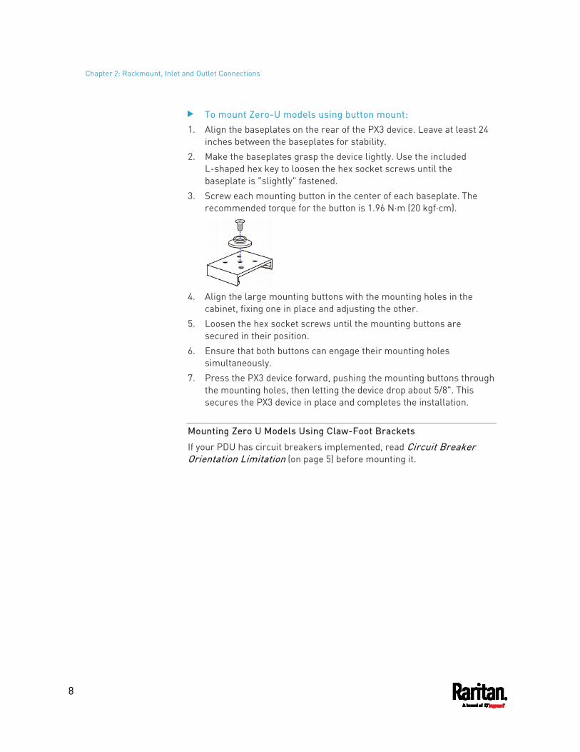
Chapter 2: Rackmount, Inlet and Outlet Connections
8
To mount Zero-U models using button mount: 1. Align the baseplates on the rear of the PX3 device. Leave at least 24
inches between the baseplates for stability. 2. Make the baseplates grasp the device lightly. Use the included
L-shaped hex key to loosen the hex socket screws until the baseplate is "slightly" fastened.
3. Screw each mounting button in the center of each baseplate. The recommended torque for the button is 1.96 N·m (20 kgf·cm).
4. Align the large mounting buttons with the mounting holes in the
cabinet, fixing one in place and adjusting the other. 5. Loosen the hex socket screws until the mounting buttons are
secured in their position. 6. Ensure that both buttons can engage their mounting holes
simultaneously. 7. Press the PX3 device forward, pushing the mounting buttons through
the mounting holes, then letting the device drop about 5/8". This secures the PX3 device in place and completes the installation.
Mounting Zero U Models Using Claw-Foot Brackets
If your PDU has circuit breakers implemented, read Circuit Breaker Orientation Limitation (on page 5) before mounting it.

Chapter 2: Rackmount, Inlet and Outlet Connections
9
To mount Zero U models using claw-foot brackets: 1. Align the baseplates on the rear of the PX3 device. 2. Secure the baseplates in place. Use the included L-shaped hex key
to loosen the hex socket screws until the baseplate is "slightly" fastened.
3. Align the claw-foot brackets with the baseplates so that the five screw-holes on the baseplates line up through the bracket's slots. The rackmount side of brackets should face either the left or right side of the PX3 device.
4. Fasten the brackets in place with at least three screws (one through each slot). Use additional screws as desired.
5. Using rack screws, fasten the PX3 device to the rack through the
claw-foot brackets.
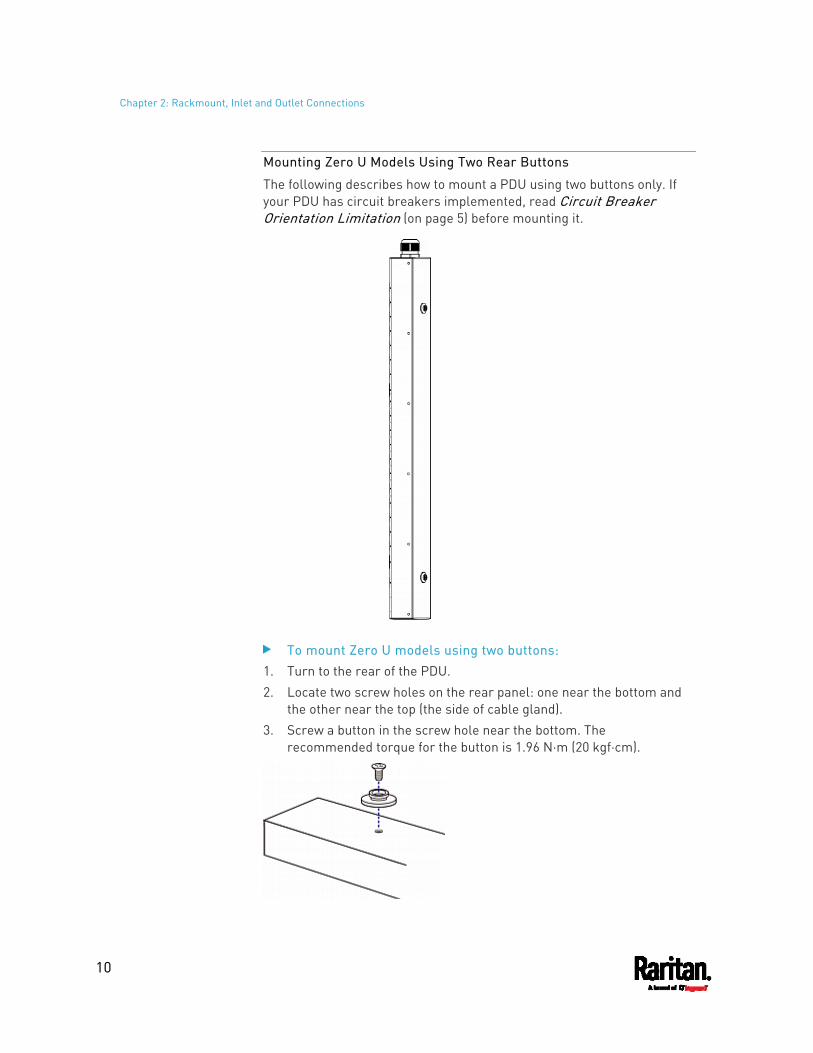
Chapter 2: Rackmount, Inlet and Outlet Connections
10
Mounting Zero U Models Using Two Rear Buttons
The following describes how to mount a PDU using two buttons only. If your PDU has circuit breakers implemented, read Circuit Breaker Orientation Limitation (on page 5) before mounting it.
To mount Zero U models using two buttons: 1. Turn to the rear of the PDU. 2. Locate two screw holes on the rear panel: one near the bottom and
the other near the top (the side of cable gland). 3. Screw a button in the screw hole near the bottom. The
recommended torque for the button is 1.96 N·m (20 kgf·cm).

Chapter 2: Rackmount, Inlet and Outlet Connections
11
4. Screw a button in the screw hole near the top. The recommended torque for the button is 1.96 N·m (20 kgf·cm).
5. Ensure that the two buttons can engage their mounting holes in the rack or cabinet simultaneously.
6. Press the PX3 device forward, pushing the mounting buttons through the mounting holes, then letting the device drop slightly. This secures the PX3 device in place and completes the installation.
Mounting 1U or 2U Models
Using the appropriate brackets and tools, fasten the 1U or 2U device to the rack or cabinet.
To mount the PX3 device: 1. Attach a rackmount bracket to both sides of the PX3 with the
provided screws.
2. Insert the cable-support bar into rackmount brackets.
3. Secure with the provided end cap screws.
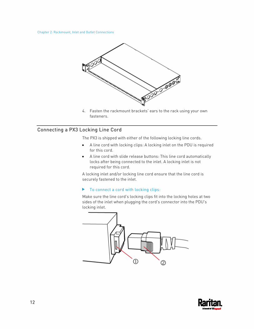
Chapter 2: Rackmount, Inlet and Outlet Connections
12
4. Fasten the rackmount brackets' ears to the rack using your own
fasteners.
Connecting a PX3 Locking Line Cord
The PX3 is shipped with either of the following locking line cords.
A line cord with locking clips: A locking inlet on the PDU is required for this cord.
A line cord with slide release buttons: This line cord automatically locks after being connected to the inlet. A locking inlet is not required for this cord.
A locking inlet and/or locking line cord ensure that the line cord is securely fastened to the inlet.
To connect a cord with locking clips:
Make sure the line cord's locking clips fit into the locking holes at two sides of the inlet when plugging the cord's connector into the PDU's locking inlet.
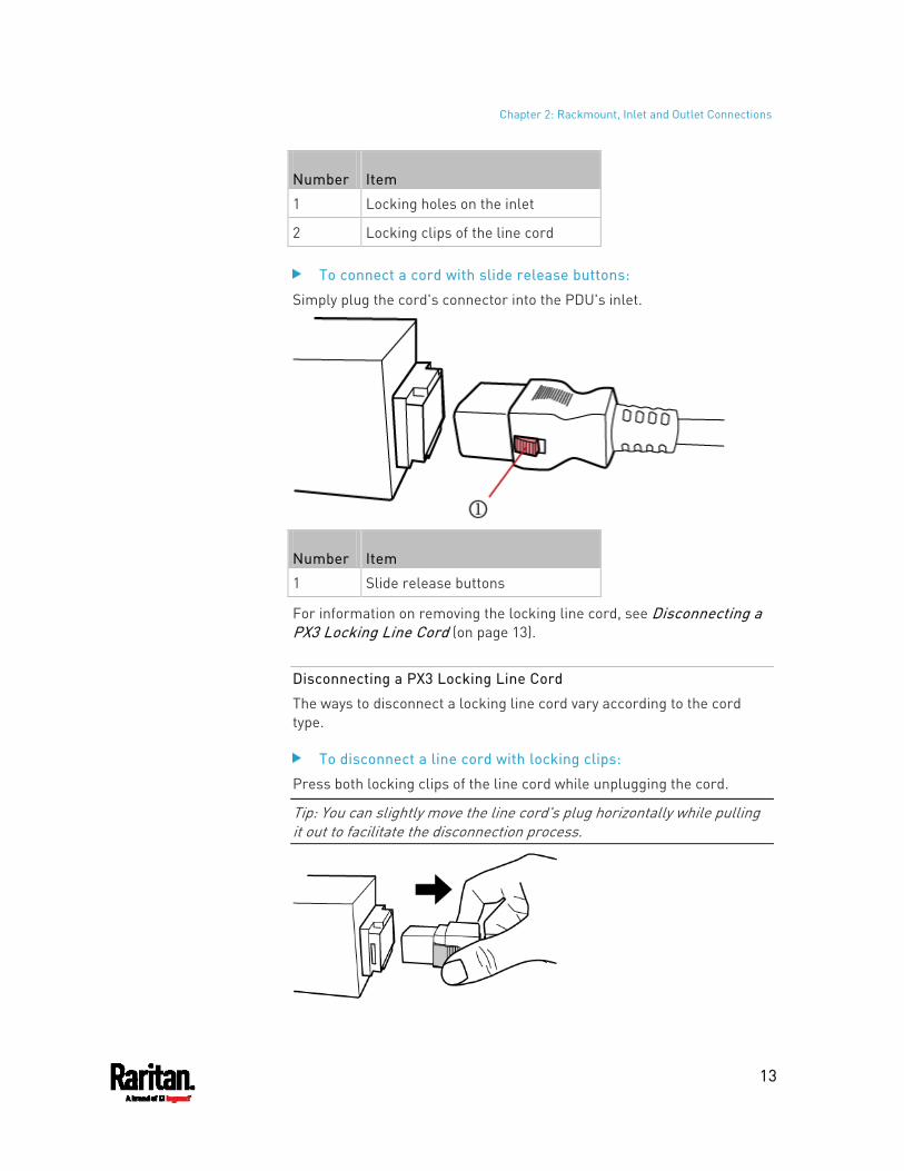
Chapter 2: Rackmount, Inlet and Outlet Connections
13
Number Item
1 Locking holes on the inlet
2 Locking clips of the line cord
To connect a cord with slide release buttons:
Simply plug the cord's connector into the PDU's inlet.
Number Item
1 Slide release buttons
For information on removing the locking line cord, see Disconnecting a PX3 Locking Line Cord (on page 13).
Disconnecting a PX3 Locking Line Cord
The ways to disconnect a locking line cord vary according to the cord type.
To disconnect a line cord with locking clips:
Press both locking clips of the line cord while unplugging the cord.
Tip: You can slightly move the line cord's plug horizontally while pulling it out to facilitate the disconnection process.
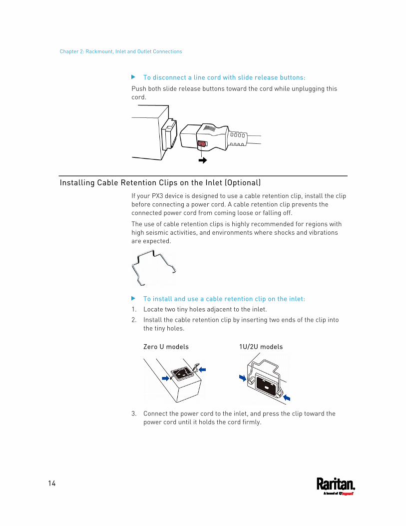
Chapter 2: Rackmount, Inlet and Outlet Connections
14
To disconnect a line cord with slide release buttons:
Push both slide release buttons toward the cord while unplugging this cord.
Installing Cable Retention Clips on the Inlet (Optional)
If your PX3 device is designed to use a cable retention clip, install the clip before connecting a power cord. A cable retention clip prevents the connected power cord from coming loose or falling off.
The use of cable retention clips is highly recommended for regions with high seismic activities, and environments where shocks and vibrations are expected.
To install and use a cable retention clip on the inlet: 1. Locate two tiny holes adjacent to the inlet. 2. Install the cable retention clip by inserting two ends of the clip into
the tiny holes.
Zero U models 1U/2U models
3. Connect the power cord to the inlet, and press the clip toward the power cord until it holds the cord firmly.
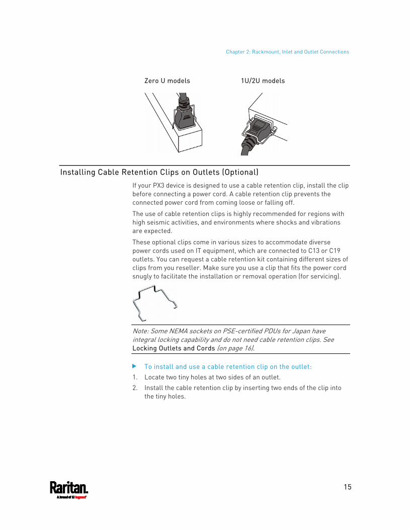
Chapter 2: Rackmount, Inlet and Outlet Connections
15
Zero U models 1U/2U models
Installing Cable Retention Clips on Outlets (Optional)
If your PX3 device is designed to use a cable retention clip, install the clip before connecting a power cord. A cable retention clip prevents the connected power cord from coming loose or falling off.
The use of cable retention clips is highly recommended for regions with high seismic activities, and environments where shocks and vibrations are expected.
These optional clips come in various sizes to accommodate diverse power cords used on IT equipment, which are connected to C13 or C19 outlets. You can request a cable retention kit containing different sizes of clips from you reseller. Make sure you use a clip that fits the power cord snugly to facilitate the installation or removal operation (for servicing).
Note: Some NEMA sockets on PSE-certified PDUs for Japan have integral locking capability and do not need cable retention clips. See Locking Outlets and Cords (on page 16).
To install and use a cable retention clip on the outlet: 1. Locate two tiny holes at two sides of an outlet. 2. Install the cable retention clip by inserting two ends of the clip into
the tiny holes.
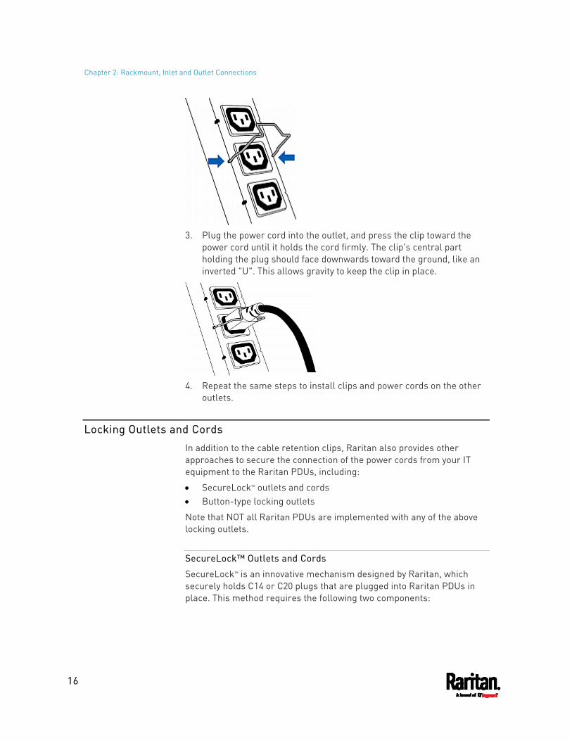
Chapter 2: Rackmount, Inlet and Outlet Connections
16
3. Plug the power cord into the outlet, and press the clip toward the
power cord until it holds the cord firmly. The clip's central part holding the plug should face downwards toward the ground, like an inverted "U". This allows gravity to keep the clip in place.
4. Repeat the same steps to install clips and power cords on the other
outlets.
Locking Outlets and Cords
In addition to the cable retention clips, Raritan also provides other approaches to secure the connection of the power cords from your IT equipment to the Raritan PDUs, including:
SecureLock™ outlets and cords Button-type locking outlets
Note that NOT all Raritan PDUs are implemented with any of the above locking outlets.
SecureLock™ Outlets and Cords
SecureLock™ is an innovative mechanism designed by Raritan, which securely holds C14 or C20 plugs that are plugged into Raritan PDUs in place. This method requires the following two components:
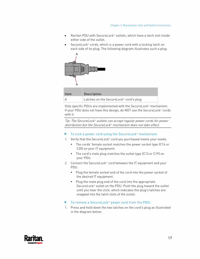
Chapter 2: Rackmount, Inlet and Outlet Connections
17
Raritan PDU with SecureLock™ outlets, which have a latch slot inside either side of the outlet.
SecureLock™ cords, which is a power cord with a locking latch on each side of its plug. The following diagram illustrates such a plug.
Item Description
A Latches on the SecureLock™ cord's plug
Only specific PDUs are implemented with the SecureLock™ mechanism. If your PDU does not have this design, do NOT use the SecureLock™ cords with it.
Tip: The SecureLock™ outlets can accept regular power cords for power distribution but the SecureLock™ mechanism does not take effect.
To lock a power cord using the SecureLock™ mechanism: 1. Verify that the SecureLock™ cord you purchased meets your needs.
The cords' female socket matches the power socket type (C14 or C20) on your IT equipment.
The cord's male plug matches the outlet type (C13 or C19) on your PDU.
2. Connect the SecureLock™ cord between the IT equipment and your PDU. Plug the female socket end of the cord into the power socket of
the desired IT equipment. Plug the male plug end of the cord into the appropriate
SecureLock™ outlet on the PDU. Push the plug toward the outlet until you hear the click, which indicates the plug's latches are snapped into the latch slots of the outlet.
To remove a SecureLock™ power cord from the PDU: 1. Press and hold down the two latches on the cord's plug as illustrated
in the diagram below.
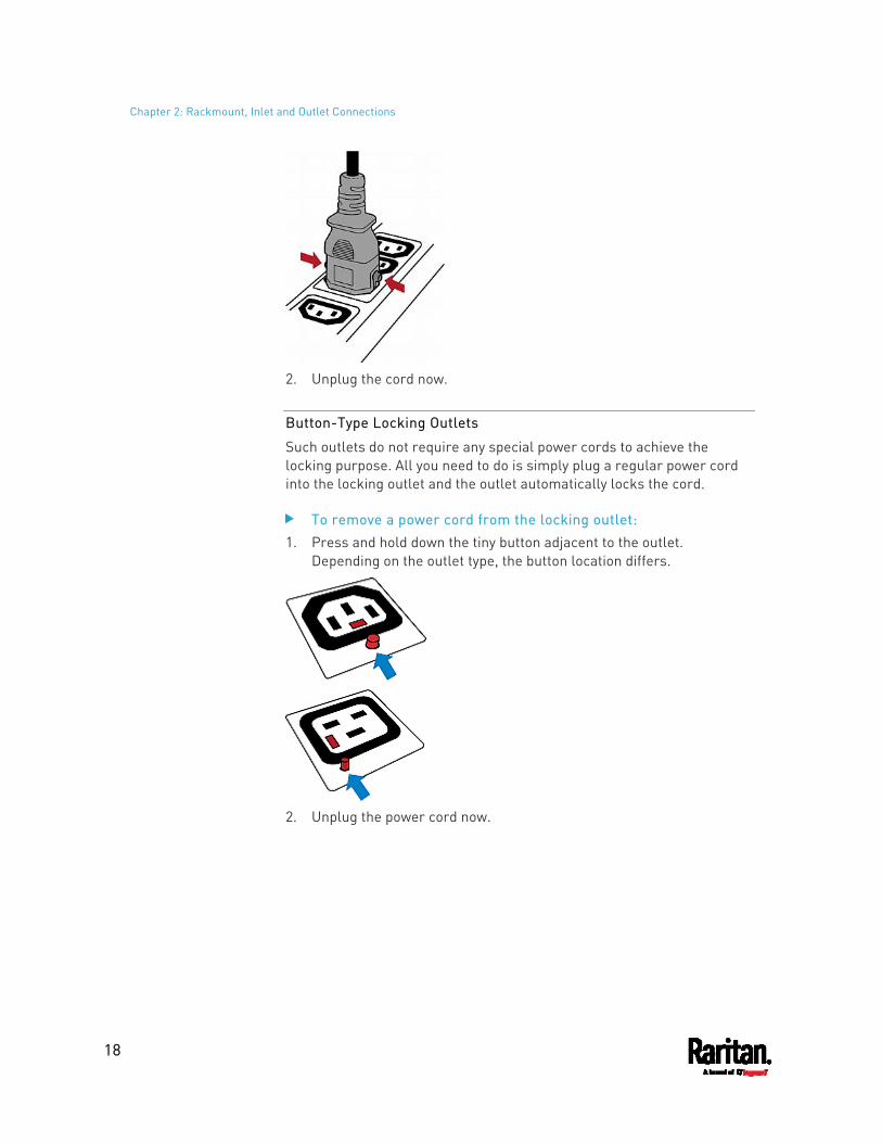
Chapter 2: Rackmount, Inlet and Outlet Connections
18
2. Unplug the cord now.
Button-Type Locking Outlets
Such outlets do not require any special power cords to achieve the locking purpose. All you need to do is simply plug a regular power cord into the locking outlet and the outlet automatically locks the cord.
To remove a power cord from the locking outlet: 1. Press and hold down the tiny button adjacent to the outlet.
Depending on the outlet type, the button location differs.
2. Unplug the power cord now.
19
This chapter explains how to install your PX3 and configure it for network connectivity.
In This Chapter
Connecting the PDU to a Power Source ...................................................19 Connecting the PX3 to Your Network........................................................19 Configuring the PX3...................................................................................22 Bulk Configuration Methods .....................................................................31 Cascading Multiple PX3 Devices for Sharing Ethernet Connectivity........32 Power-Sharing Restrictions and Connection ...........................................41
Connecting the PDU to a Power Source
1. Verify that all circuit breakers on the PX3 are set to ON. If not, turn them ON. Or make sure that all fuses are inserted and seated properly. If there are any fuse covers, ensure that they are closed.
Note: Not all models have overcurrent protectors.
2. Connect each PX3 to an appropriately rated branch circuit. See the label or nameplate affixed to your PX3 for appropriate input ratings or range of ratings.
Note: When a PX3 powers up, it proceeds with the power-on self test and software loading for a few moments. At this time, the outlet LEDs cycle through different colors. Note that outlet LEDs are only available on some PDU models.
3. When the software has completed loading, the outlet LEDs show a steady color and the front panel display illuminates.
Connecting the PX3 to Your Network
To remotely administer the PX3, you must connect the PX3 to your local area network (LAN). PX3 can be connected to a wired or wireless network.
Note: If your PX3 will work as a master device in the bridging mode, you must make a wired connection. See Cascading Multiple PX3 Devices for Sharing Ethernet Connectivity (on page 32).
Chapter 3 Initial Installation and Configuration
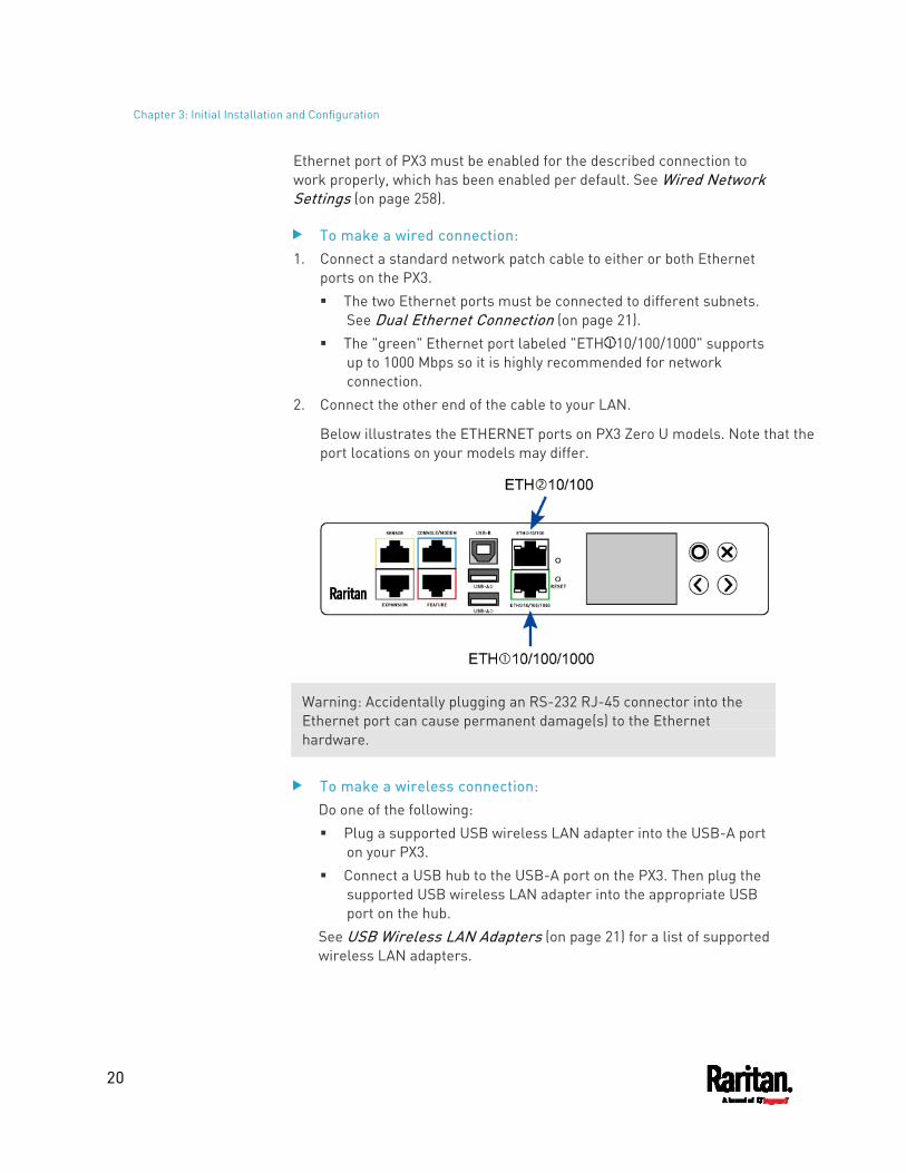
Chapter 3: Initial Installation and Configuration
20
Ethernet port of PX3 must be enabled for the described connection to work properly, which has been enabled per default. See Wired Network Settings (on page 258).
To make a wired connection: 1. Connect a standard network patch cable to either or both Ethernet
ports on the PX3. The two Ethernet ports must be connected to different subnets.
See Dual Ethernet Connection (on page 21). The "green" Ethernet port labeled "ETH 10/100/1000" supports
up to 1000 Mbps so it is highly recommended for network connection.
2. Connect the other end of the cable to your LAN.
Below illustrates the ETHERNET ports on PX3 Zero U models. Note that the port locations on your models may differ.
Warning: Accidentally plugging an RS-232 RJ-45 connector into the Ethernet port can cause permanent damage(s) to the Ethernet hardware.
To make a wireless connection: Do one of the following: Plug a supported USB wireless LAN adapter into the USB-A port
on your PX3. Connect a USB hub to the USB-A port on the PX3. Then plug the
supported USB wireless LAN adapter into the appropriate USB port on the hub.
See USB Wireless LAN Adapters (on page 21) for a list of supported wireless LAN adapters.
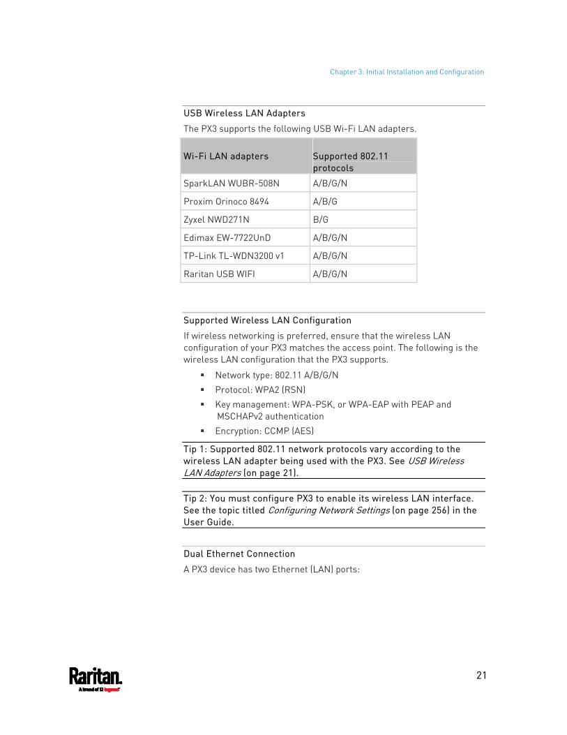
Chapter 3: Initial Installation and Configuration
21
USB Wireless LAN Adapters
The PX3 supports the following USB Wi-Fi LAN adapters.
Wi-Fi LAN adapters Supported 802.11 protocols
SparkLAN WUBR-508N A/B/G/N
Proxim Orinoco 8494 A/B/G
Zyxel NWD271N B/G
Edimax EW-7722UnD A/B/G/N
TP-Link TL-WDN3200 v1 A/B/G/N
Raritan USB WIFI A/B/G/N
Supported Wireless LAN Configuration
If wireless networking is preferred, ensure that the wireless LAN configuration of your PX3 matches the access point. The following is the wireless LAN configuration that the PX3 supports.
Network type: 802.11 A/B/G/N Protocol: WPA2 (RSN) Key management: WPA-PSK, or WPA-EAP with PEAP and
MSCHAPv2 authentication Encryption: CCMP (AES)
Tip 1: Supported 802.11 network protocols vary according to the wireless LAN adapter being used with the PX3. See USB Wireless LAN Adapters (on page 21).
Tip 2: You must configure PX3 to enable its wireless LAN interface. See the topic titled Configuring Network Settings (on page 256) in the User Guide.
Dual Ethernet Connection
A PX3 device has two Ethernet (LAN) ports:
Chapter 3: Initial Installation and Configuration
22
ETH 10/100/1000 (marked in green) supports up to 1000 Mbps. This is "ETH1".
ETH 10/100 (marked in white) supports up to 100 Mbps. This is "ETH2".
For more information on the two ports, see Connection Port Functions (on page 81).
You can connect both ports to different subnets (networks) and therefore obtain two IP addresses for wired networking. It is strongly recommended that you DO NOT connect both ports to the same subnet to avoid potential issues. Contact your IT department if you are not sure whether the two Ethernet ports are connecting to the same or different subnets.
Exception: A USB-cascading chain must connect to "only one" network. Do NOT connect both Ethernet ports of any PX3 master or slave device to the LAN. See Cascading Multiple PX3 Devices for Sharing Ethernet Connectivity (on page 32).
Check list when connecting both ports to the networks: Both Ethernet interfaces are connecting to different subnets. Both Ethernet interfaces have been enabled. By default both are
enabled. See Device Info (on page 115) and Ethernet Interface Settings (on page 260).
Both Ethernet interfaces are configured with proper IPv4 and/or IPv6 settings. See Wired Network Settings (on page 258). It is NOT required that the two Ethernet interfaces share similar
network settings. For example, you can enable IPv4 settings in one interface but enable IPv6 settings in the other, or apply static IP to one but DHCP IP to the other.
The cascading mode is disabled. By default it is disabled. See Setting the Cascading Mode (on page 269).
Configuring the PX3
You can initially configure the PX3 via one of the following:
A TCP/IP network that supports DHCP A mobile device with PDView installed A computer physically connected to the PX3
Configuration via a DHCP-enabled network: 1. Connect the PX3 to a DHCP IPv4 network. See Connecting the PX3
to Your Network (on page 19).
Chapter 3: Initial Installation and Configuration
23
2. Retrieve the DHCP-assigned IPv4 address. Use the front panel LCD display to retrieve it. See Device Info (on page 115).
3. Launch a web browser to configure the PX3. See Login (on page 133).
Configuration via a connected mobile device: 1. Download the PDView app to your mobile device. See Connecting a
Mobile Device to PX3 (on page 23). 2. Connect the mobile device to PX3 via USB. 3. Launch PDView to configure the PX3.
Configuration via a connected computer: 1. Connect the PX3 to a computer. See Connecting the PX3 to a
Computer (on page 28). 2. Use the connected computer to configure the PX3 via the command
line or web interface. Command line interface: See Initial Network Configuration via
CLI (on page 828). Web interface: Launch the web browser on the computer, and
type the link-local IP address or pdu.local to access the PX3. See Login (on page 133). For link-local IP address retrieval, see Device Info (on page 115).
Tip: To configure a number of PX3 devices quickly, see Bulk Configuration Methods (on page 31).
Connecting a Mobile Device to PX3
Raritan's PDView is a free app that turns your iOS or Android mobile device into a local display for PX3.
PDView is especially helpful when your PX3 is not connected to the network but you need to check the PX3 status, retrieve its information, or change its settings.
Requirements for using PDView: PX3 is running any post-3.0.0 firmware version. If using an Android device, it must support USB "On-The-Go" (OTG). An appropriate USB cable is required. For information, refer to Step
B below.
Step A: Download and install PDView 1. Visit either Apple App or Google Play Store.
https://itunes.apple.com/app/raritan-pdview/id780382738
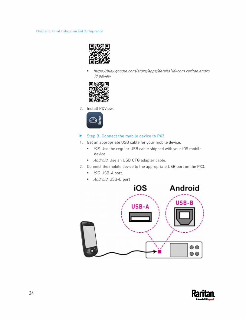
Chapter 3: Initial Installation and Configuration
24
https://play.google.com/store/apps/details?id=com.raritan.andro
id.pdview
2. Install PDView.
Step B: Connect the mobile device to PX3 1. Get an appropriate USB cable for your mobile device.
iOS: Use the regular USB cable shipped with your iOS mobile device.
Android: Use an USB OTG adapter cable. 2. Connect the mobile device to the appropriate USB port on the PX3.
iOS: USB-A port. Android: USB-B port
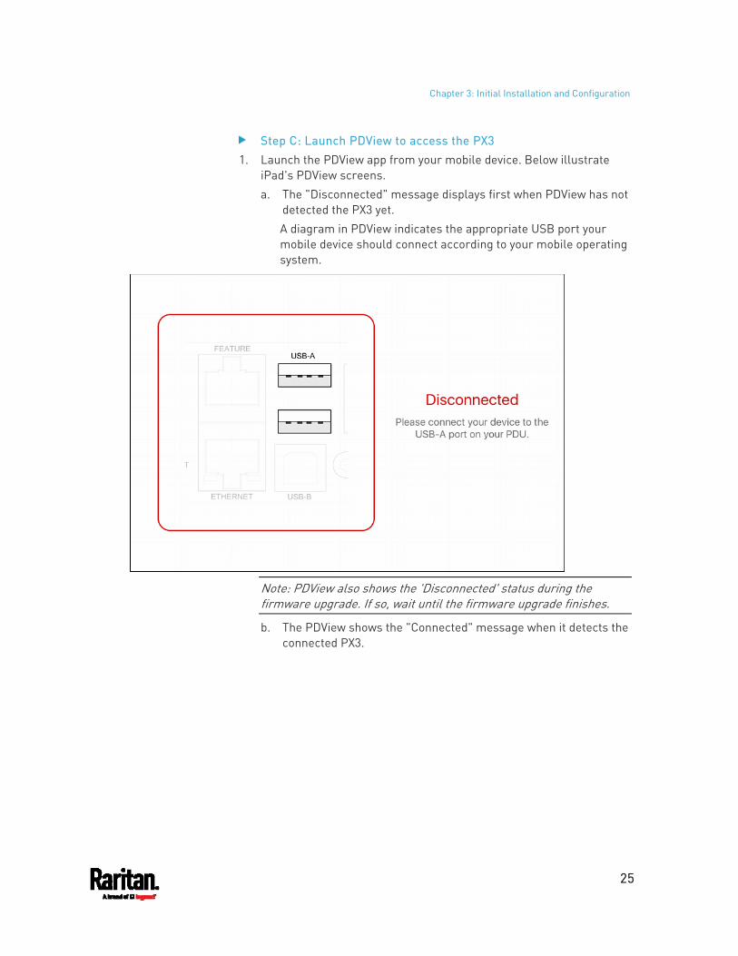
Chapter 3: Initial Installation and Configuration
25
Step C: Launch PDView to access the PX3 1. Launch the PDView app from your mobile device. Below illustrate
iPad's PDView screens. a. The "Disconnected" message displays first when PDView has not
detected the PX3 yet. A diagram in PDView indicates the appropriate USB port your mobile device should connect according to your mobile operating system.
Note: PDView also shows the 'Disconnected' status during the firmware upgrade. If so, wait until the firmware upgrade finishes.
b. The PDView shows the "Connected" message when it detects the connected PX3.
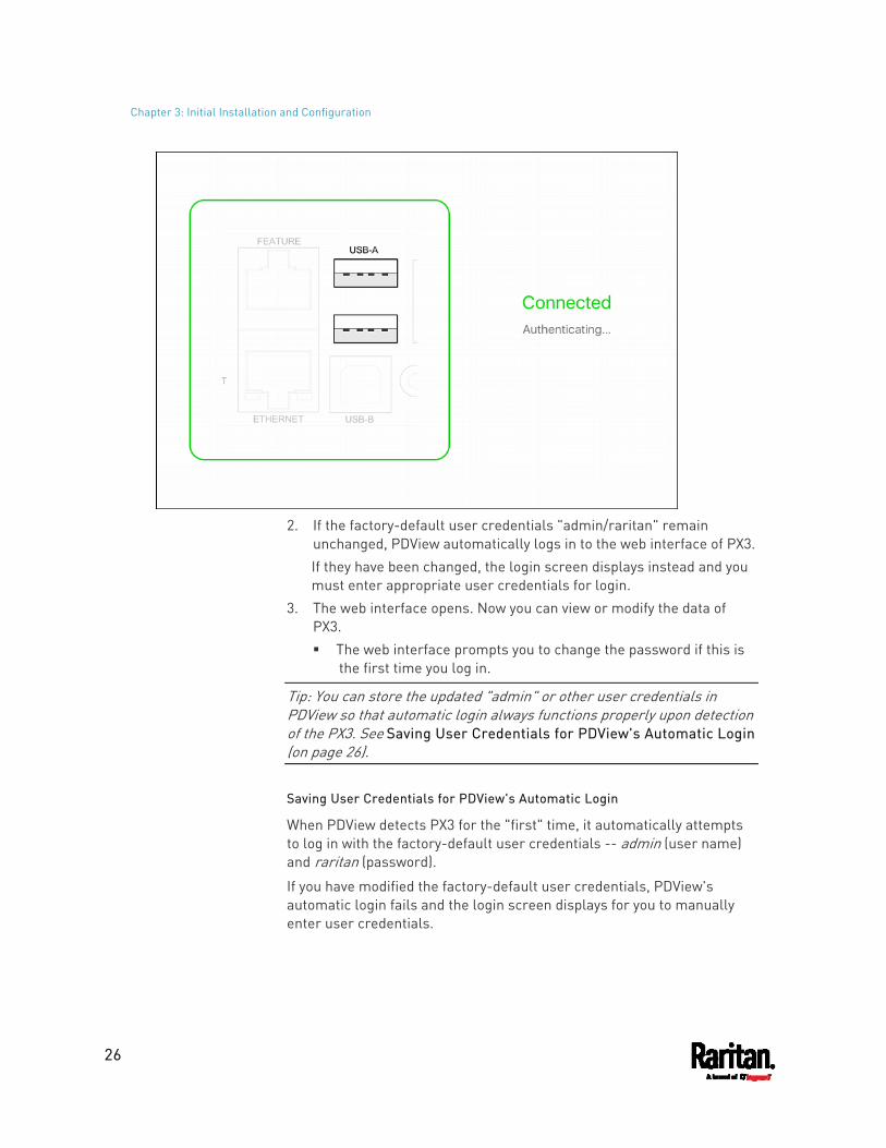
Chapter 3: Initial Installation and Configuration
26
2. If the factory-default user credentials "admin/raritan" remain
unchanged, PDView automatically logs in to the web interface of PX3. If they have been changed, the login screen displays instead and you must enter appropriate user credentials for login.
3. The web interface opens. Now you can view or modify the data of PX3. The web interface prompts you to change the password if this is
the first time you log in.
Tip: You can store the updated "admin" or other user credentials in PDView so that automatic login always functions properly upon detection of the PX3. See Saving User Credentials for PDView's Automatic Login (on page 26).
Saving User Credentials for PDView's Automatic Login
When PDView detects PX3 for the "first" time, it automatically attempts to log in with the factory-default user credentials -- admin (user name) and raritan (password).
If you have modified the factory-default user credentials, PDView's automatic login fails and the login screen displays for you to manually enter user credentials.
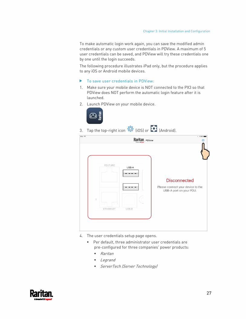
Chapter 3: Initial Installation and Configuration
27
To make automatic login work again, you can save the modified admin credentials or any custom user credentials in PDView. A maximum of 5 user credentials can be saved, and PDView will try these credentials one by one until the login succeeds.
The following procedure illustrates iPad only, but the procedure applies to any iOS or Android mobile devices.
To save user credentials in PDView: 1. Make sure your mobile device is NOT connected to the PX3 so that
PDView does NOT perform the automatic login feature after it is launched.
2. Launch PDView on your mobile device.
3. Tap the top-right icon (iOS) or (Android).
4. The user credentials setup page opens.
Per default, three administrator user credentials are pre-configured for three companies' power products: Raritan Legrand ServerTech (Server Technology)
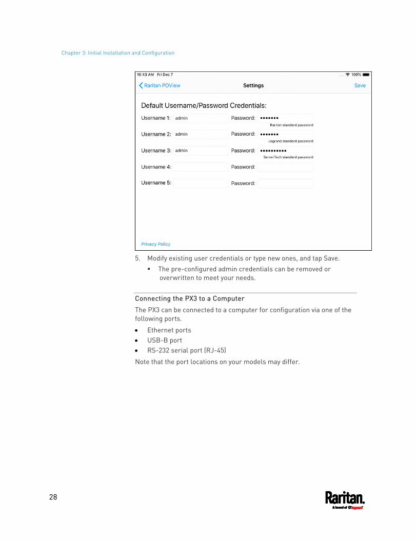
Chapter 3: Initial Installation and Configuration
28
5. Modify existing user credentials or type new ones, and tap Save.
The pre-configured admin credentials can be removed or overwritten to meet your needs.
Connecting the PX3 to a Computer
The PX3 can be connected to a computer for configuration via one of the following ports.
Ethernet ports USB-B port RS-232 serial port (RJ-45)
Note that the port locations on your models may differ.
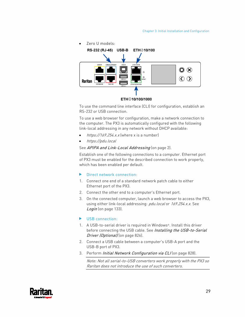
Chapter 3: Initial Installation and Configuration
29
Zero U models:
To use the command line interface (CLI) for configuration, establish an RS-232 or USB connection.
To use a web browser for configuration, make a network connection to the computer. The PX3 is automatically configured with the following link-local addressing in any network without DHCP available:
https://169.254.x.x (where x is a number) https://pdu.local See APIPA and Link-Local Addressing (on page 2).
Establish one of the following connections to a computer. Ethernet port of PX3 must be enabled for the described connection to work properly, which has been enabled per default.
Direct network connection: 1. Connect one end of a standard network patch cable to either
Ethernet port of the PX3. 2. Connect the other end to a computer's Ethernet port. 3. On the connected computer, launch a web browser to access the PX3,
using either link-local addressing: pdu.local or 169.254.x.x. See Login (on page 133).
USB connection: 1. A USB-to-serial driver is required in Windows®. Install this driver
before connecting the USB cable. See Installing the USB-to-Serial Driver (Optional) (on page 826).
2. Connect a USB cable between a computer's USB-A port and the USB-B port of PX3.
3. Perform Initial Network Configuration via CLI (on page 828).
Note: Not all serial-to-USB converters work properly with the PX3 so Raritan does not introduce the use of such converters.
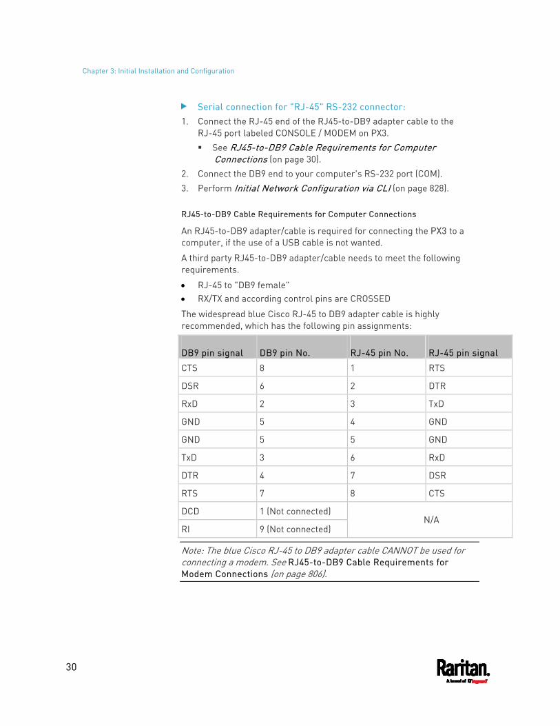
Chapter 3: Initial Installation and Configuration
30
Serial connection for "RJ-45" RS-232 connector: 1. Connect the RJ-45 end of the RJ45-to-DB9 adapter cable to the
RJ-45 port labeled CONSOLE / MODEM on PX3. See RJ45-to-DB9 Cable Requirements for Computer
Connections (on page 30). 2. Connect the DB9 end to your computer's RS-232 port (COM). 3. Perform Initial Network Configuration via CLI (on page 828).
RJ45-to-DB9 Cable Requirements for Computer Connections
An RJ45-to-DB9 adapter/cable is required for connecting the PX3 to a computer, if the use of a USB cable is not wanted.
A third party RJ45-to-DB9 adapter/cable needs to meet the following requirements.
RJ-45 to "DB9 female" RX/TX and according control pins are CROSSED
The widespread blue Cisco RJ-45 to DB9 adapter cable is highly recommended, which has the following pin assignments:
DB9 pin signal DB9 pin No. RJ-45 pin No. RJ-45 pin signal
CTS 8 1 RTS
DSR 6 2 DTR
RxD 2 3 TxD
GND 5 4 GND
GND 5 5 GND
TxD 3 6 RxD
DTR 4 7 DSR
RTS 7 8 CTS
DCD 1 (Not connected)
RI 9 (Not connected) N/A
Note: The blue Cisco RJ-45 to DB9 adapter cable CANNOT be used for connecting a modem. See RJ45-to-DB9 Cable Requirements for Modem Connections (on page 806).
Chapter 3: Initial Installation and Configuration
31
Bulk Configuration Methods
If you have to set up multiple PX3 devices, you can use one of the following configuration methods to save your time.
A bulk configuration file downloaded from PX3: Requirement: All PX3 devices to configure are of the same model
and firmware. Procedure: First finish configuring one PX3. Then download the bulk
configuration file from it and copy this file to all of the other PX3 devices. See Bulk Configuration (on page 418).
A TFTP server: Requirement: DHCP is enabled in your network and a TFTP server is
available. Procedure: Prepare special configuration files, which must include
fwupdate.cfg, and copy them to the root directory of the TFTP server. Re-boot all PX3 devices after connecting them to the network. See Bulk Configuration or Firmware Upgrade via DHCP/TFTP (on page 688).
Curl command: Requirement: Two files are required -- one is a configuration file in
TXT and the other is a devices list file in CSV. See config.txt (on page 680) and devices.csv (on page 682).
Procedure: Upload both files to all of PX3 devices one by one, using the appropriate curl command. See Upload via Curl (on page 714).
SCP or PSCP command: Requirement: Two files are required -- one is a configuration file in
TXT and the other is a devices list file in CSV. Procedure: Upload both files to all of PX3 devices one by one, using
the appropriate SCP or PSCP command. See Uploading or Downloading Raw Configuration Data (on page 645).
Chapter 3: Initial Installation and Configuration
32
A USB flash drive: Requirement: A FAT32- or supperfloppy-formatted USB flash drive
containing two special configuration files and one devices list file is required.
Procedure: Plug this USB drive into the PX3. When a happy smiley is shown on the front panel display, press and hold one of the control buttons on the front panel until the display turns blank. See Configuration or Firmware Upgrade with a USB Drive (on page 673).
Cascading Multiple PX3 Devices for Sharing Ethernet Connectivity
Important: To upgrade an existing Raritan USB-cascading chain from any pre-3.3.10 firmware version to version 3.3.10 or later, follow the Upgrade Sequence in an Existing Cascading Chain (on page 415).
You can have multiple PX3 devices share one Ethernet connection by cascading them via one of the interfaces below:
USB interface Ethernet interface
The first one in the cascading chain is the master device and all the other are slave devices. Only the master device is physically connected to the LAN -- wired or wireless.
Each device in the chain is accessible over the network, with the Bridging or Port-Forwarding cascading mode activated on the master device. See Setting the Cascading Mode (on page 269).
Bridging: Each device in the cascading chain is accessed with a different IP address.
Port Forwarding: Each device in the cascading chain is accessed with the same IP address(es) but with a different port number assigned.
Basic cascading restrictions: All devices in the chain must run "compatible" firmware versions.
Firmware version 3.3.10 or later is NOT compatible with pre-3.3.10 firmware versions in terms of the cascading feature so all Raritan devices in the cascading chain must run version 3.3.10 or later.
Chapter 3: Initial Installation and Configuration
33
The cascading mode of all devices in the chain must be the same. In the Bridging mode, the master device can have "only one"
connection to the network. DO NOT connect both Ethernet ports to the network(s) unless your network has the R/STP protocol enabled.
Note: The Port Forwarding mode does NOT have this restriction. In this mode, you can enable two wired and one wireless network connections.
Do NOT connect slave devices to the LAN or WLAN. (WIFI only) You must use Raritan's USB WIFI wireless LAN adapter
instead of other WIFI adapters for wireless network connection.
Troubleshooting: When a networking issue occurs, check the cascading connection and/or software settings of all devices in the chain. See Cascading Troubleshooting (on page 822).
Online Cascading Guide:
For detailed information on the cascading configuration and restrictions, refer to the Cascading Guide, which is available from Raritan website's Support page (http://www.raritan.com/support/).
Cascading All Devices via USB
You must set the cascading mode before establishing the chain. See Setting the Cascading Mode (on page 269).
Any certified USB 2.0 cable up to 5 meters (16 feet) long can be used.
Both cascading modes support a maximum of 16 devices in a chain.
The following diagram illustrates PX3 devices cascaded via USB.
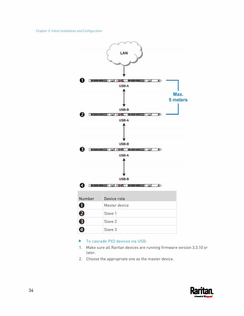
Chapter 3: Initial Installation and Configuration
34
Number Device role
Master device
Slave 1
Slave 2
Slave 3
To cascade PX3 devices via USB: 1. Make sure all Raritan devices are running firmware version 3.3.10 or
later. 2. Choose the appropriate one as the master device.
Chapter 3: Initial Installation and Configuration
35
When the Port Forwarding mode over "wireless LAN" is intended, the master device must be a Raritan product with two USB-A ports, such as PX3, EMX2-888, PX3TS or BCM2.
3. Log in to all devices one by one and select the same cascading mode. Bridging mode:
Set the cascading mode of all devices to Bridging. Port Forwarding mode:
Set the cascading mode of all devices to Port Forwarding. Make sure the cascading role and downstream interface are also set correctly.
See Setting the Cascading Mode (on page 269). 4. Connect the master device to the LAN, using a method below.
Bridging mode: Use a standard network patch cable (CAT5e or higher).
Port Forwarding mode: Use a standard network patch cable and/or a Raritan USB WIFI wireless LAN adapter. For information on the Raritan USB WIFI adapter, see USB Wireless LAN Adapters (on page 21).
5. Connect the USB-A port of the master device to the USB-B port of an additional PX3 via a USB cable. This additional device is Slave 1.
6. Connect Slave 1's USB-A port to the USB-B port of an additional PX3 via another USB cable. The second additional device is Slave 2.
7. Repeat the same step to connect more slave devices. You can cascade up to 15 slave devices.
8. (Optional) Configure or change the network settings of the master and/or slave devices as needed. See Configuring Network Settings (on page 256). Bridging mode: Each cascaded device has its own network
settings. For example, you can have some devices use DHCP-assigned IP addresses and the others use static IP addresses.
Port Forwarding mode: Only the master device's network settings should be configured.
A tip for USB cascading:
The "USB-cascading" chain can be a combination of diverse Raritan products that support the USB-cascading feature, including PX2, PX3, PXC, transfer switch, BCM and EMX.
Chapter 3: Initial Installation and Configuration
36
Extended Cascading with PX3 Devices
PX3 supports cascading via either Ethernet or USB ports. This is because they have "two" Ethernet ports.
You can use either Ethernet port on the PX3 PDU for cascading.
You must set the cascading mode before establishing the chain. See Setting the Cascading Mode (on page 269).
Both cascading modes support a maximum of 16 devices in a chain.
When establishing a Port-Forwarding chain, make sure you follow the guidelines described in the section titled Restrictions of Port-Forwarding Connections (on page 39).
You can mix Ethernet and USB cascading in the PX3 PDU chain if preferred. The following diagram illustrates such a chain.
The distance between two Ethernet-cascaded devices can be up to 100 meters, while the distance between two USB-cascaded devices supports up to 5 meters only.
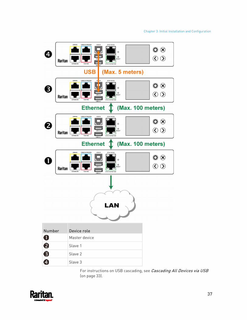
Chapter 3: Initial Installation and Configuration
37
Number Device role
Master device
Slave 1
Slave 2
Slave 3
For instructions on USB cascading, see Cascading All Devices via USB (on page 33).
Chapter 3: Initial Installation and Configuration
38
Suggestions for extended cascading: Ethernet cascading is recommended because of the longer distance,
lower latency and more reliable connection it supports. The 'green' ETH1 port (ETH 10/100/1000) on a Raritan master
device is recommended for network connection because it supports up to 1000 Mbps.
To cascade PX3 PDUs via Ethernet ports: 1. Make sure all Raritan devices are running firmware version 3.3.10 or
later. 2. Choose one PX3 as the master device. 3. Log in to all devices one by one and select the same cascading mode.
Bridging mode: Set the cascading mode of all devices to Bridging.
Port Forwarding mode: Set the cascading mode of all devices to Port Forwarding. Make sure the cascading role and downstream interface are also set correctly.
See Setting the Cascading Mode (on page 269). 4. Connect the master device to the LAN, using a method below.
Bridging mode: Use a standard network patch cable (CAT5e or higher).
Port Forwarding mode: Use a standard network patch cable and/or a Raritan USB WIFI wireless LAN adapter. For information on the Raritan USB WIFI adapter, see USB Wireless LAN Adapters (on page 21).
5. Connect the available Ethernet port of the master device to either Ethernet port of another PX3 via a standard network patch cable. This additional PX3 device is Slave 1.
6. Connect Slave 1's available Ethernet port to either Ethernet port of another PX3 via a standard network patch cable. The second additional device is Slave 2.
7. Repeat the same step to connect more PX3 PDUs. You can cascade up to 15 slave devices.
8. (Optional) Configure or change the network settings of the master and/or slave devices as needed. See Configuring Network Settings (on page 256). Bridging mode: Each cascaded device has its own network
settings.
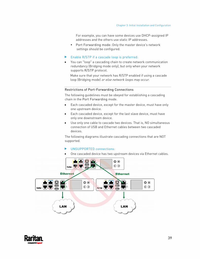
Chapter 3: Initial Installation and Configuration
39
For example, you can have some devices use DHCP-assigned IP addresses and the others use static IP addresses.
Port Forwarding mode: Only the master device's network settings should be configured.
Enable R/STP if a cascade loop is preferred: You can "loop" a cascading chain to create network communication
redundancy (Bridging mode only), but only when your network supports R/STP protocol. Make sure that your network has R/STP enabled if using a cascade loop (Bridging mode) or else network loops may occur.
Restrictions of Port-Forwarding Connections
The following guidelines must be obeyed for establishing a cascading chain in the Port Forwarding mode.
Each cascaded device, except for the master device, must have only one upstream device.
Each cascaded device, except for the last slave device, must have only one downstream device.
Use only one cable to cascade two devices. That is, NO simultaneous connection of USB and Ethernet cables between two cascaded devices.
The following diagrams illustrate cascading connections that are NOT supported.
UNSUPPORTED connections: One cascaded device has two upstream devices via Ethernet cables.
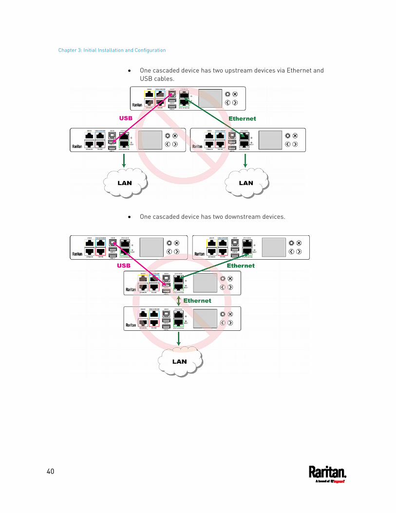
Chapter 3: Initial Installation and Configuration
40
One cascaded device has two upstream devices via Ethernet and USB cables.
One cascaded device has two downstream devices.
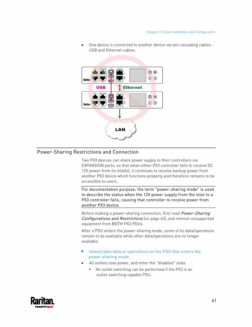
Chapter 3: Initial Installation and Configuration
41
One device is connected to another device via two cascading cables - USB and Ethernet cables.
Power-Sharing Restrictions and Connection
Two PX3 devices can share power supply to their controllers via EXPANSION ports, so that when either PX3 controller fails to receive DC 12V power from its inlet(s), it continues to receive backup power from another PX3 device which functions properly and therefore remains to be accessible to users.
For documentation purpose, the term "power-sharing mode" is used to describe the status when the 12V power supply from the inlet to a PX3 controller fails, causing that controller to receive power from another PX3 device.
Before making a power-sharing connection, first read Power-Sharing Configurations and Restrictions (on page 43), and remove unsupported equipment from BOTH PX3 PDUs.
After a PDU enters the power-sharing mode, some of its data/operations remain to be available while other data/operations are no longer available.
Unavailable data or operations on the PDU that enters the power-sharing mode:
All outlets lose power, and enter the "disabled" state. No outlet switching can be performed if the PX3 is an
outlet-switching capable PDU.
Chapter 3: Initial Installation and Configuration
42
All internal sensors become "unavailable", including sensors of inlets, outlets, and OCPs.
Exception: Only active energy data remains available.
Communications with relay/meter boards are lost. Therefore, firmware upgrade may fail due to this reason.
Available data or operations on the PDU that enters the power-sharing mode:
Change software settings, such as customizing names, modifying network settings, configuring thresholds, and so on.
Note: Outlet switching is not available because all outlets lose power.
Monitor the status of connected Raritan environmental sensor packages, or configure/control their settings.
Operate the front panel display.
Events that occur when entering the power-sharing mode: The 12V power supply sensor enters the fault state. See +12V Power
Supply Sensor (on page 163).
Tip: You can set an event rule for sending a notification when this sensor enters the fault state. See Event Rules and Actions (on page 314).
The above event is logged in the internal event log. See Default Log Messages (on page 321).
To find whether a PX3 has entered the power-sharing mode: Check the state of its +12V power supply sensor.
Tip: For SNMP, the sensor type for this +12V power supply is i1smpsStatus (46).
Making a Power-Sharing Connection
Make sure BOTH PX3 devices comply with the configuration limitations when establishing a power-sharing connection. See Power-Sharing Configurations and Restrictions (on page 43).
The supported maximum power-sharing distance is 2 meters.
Make a power-sharing connection: 1. Get a standard network patch cable (Cat5e/6), which can be up to 2
meters long. Do NOT use a crossover cable.
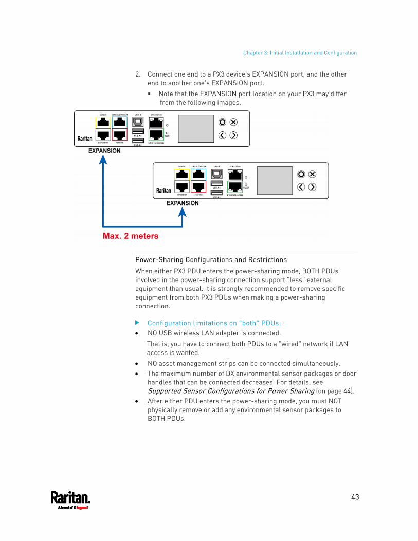
Chapter 3: Initial Installation and Configuration
43
2. Connect one end to a PX3 device's EXPANSION port, and the other end to another one's EXPANSION port. Note that the EXPANSION port location on your PX3 may differ
from the following images.
Power-Sharing Configurations and Restrictions
When either PX3 PDU enters the power-sharing mode, BOTH PDUs involved in the power-sharing connection support "less" external equipment than usual. It is strongly recommended to remove specific equipment from both PX3 PDUs when making a power-sharing connection.
Configuration limitations on "both" PDUs: NO USB wireless LAN adapter is connected.
That is, you have to connect both PDUs to a "wired" network if LAN access is wanted.
NO asset management strips can be connected simultaneously. The maximum number of DX environmental sensor packages or door
handles that can be connected decreases. For details, see Supported Sensor Configurations for Power Sharing (on page 44).
After either PDU enters the power-sharing mode, you must NOT physically remove or add any environmental sensor packages to BOTH PDUs.
Chapter 3: Initial Installation and Configuration
44
Supported Sensor Configurations for Power Sharing
All information and restrictions described in this section apply to BOTH PDUs involved in the power-sharing configuration, unless otherwise specified.
There are no limitations for connecting Raritan's DPX or DPX2 environmental sensor packages to an iX7™ PDU in the power-sharing mode. See DPX Sensor Packages (on page 54) or DPX2 Sensor Packages (on page 51).
The maximum number of supported DPX3 environmental sensor packages remains unchanged -- that is, 12 DPX3 packages. See DPX3 Sensor Packages (on page 50).
The maximum number of supported DX environmental sensor packages also remains unchanged as long as the DPX3-ENVHUB4 sensor hub is not used -- that is, 12 DX sensor packages. See DX Sensor Packages (on page 48).
The maximum number of supported DX2 environmental sensor packages remains unchanged -- that is, 12 DX2 packages. See DX2 Sensor Packages (on page 47).
However, there are DX restrictions when DPX3-ENVHUB4 is used, and there are also door handles-related restrictions.
DX sensor restrictions while DPX3-ENVHUB4 is involved: A maximum of one DPX3-ENVHUB4 and a maximum of 10 DX sensor
packages are supported.
Door handle connection restrictions (via DX2-DH2C2 or DX-PD2C5):
No connection of any "SouthCo H3-EM series" door handle(s) to DX2-DH2C2 because of insufficient power supply in the power-sharing mode.
A maximum of 2 door handles connected to a maximum of one DX2-DH2C2 or one DX-PD2C5 package are supported.
All of the 2 door handles must be controlled by the same PDU so that you can have "only one" handle opened at a time to avoid critical power consumption. That is, ALL door handles must be connected to only one PDU in the power-sharing connection, NOT both PDUs.
Note: It is strongly suggested to check and make sure the upper limit of "powered cry contact actuators" is set to 1 when making a power-sharing connection. See Peripherals (on page 207).
Chapter 3: Initial Installation and Configuration
45
Other sensor restrictions when door handles are present:
First make sure the connection of door handles complies with the above restrictions.
The following restrictions apply only to the PDU that has all the door handles connected.
When there are 2 door handles connected to the PDU (via DX2-DH2C2 or DX-PD2C5), up to 10 sensor packages of DPX/DPX2/DPX3/DX2 or up to 2 additional DX sensor packages can be additionally connected. Raritan's sensor hubs must NOT be used.
When there is only 1 handle connected, up to 12 sensor packages of DPX/DPX2/DPX3/DX2 or up to 3 DX sensor packages can be additionally connected. Raritan's sensor hubs must NOT be used.
NO physical changes made to the number of connected sensor packages:
After either PDU enters the power-sharing mode, you must NOT physically remove or add any environmental sensor packages to BOTH PDUs.
Warning: The in-rush current of a newly added sensor package may cause both PDUs to reboot.
For information on Raritan's sensor packages or hubs, see Connecting Raritan Environmental Sensor Packages (on page 46).
46
More features are available if you connect Raritan's or third-party external equipment to your PX3.
In This Chapter
Connecting Raritan Environmental Sensor Packages .............................46 Connecting Asset Management Strips......................................................65 Connecting a Logitech Webcam................................................................75 Connecting a GSM Modem ........................................................................75 Connecting an Analog Modem ..................................................................76 Connecting an External Beeper ................................................................77 Connecting a Schroff LHX/SHX Heat Exchanger ......................................77
Connecting Raritan Environmental Sensor Packages
PX3 supports all types of Raritan environmental sensor packages, including DPX, DPX2, DPX3, DX and DX2 sensor packages. DPX series is the first generation while DX2 series is the latest generation.
For detailed information on each sensor package, refer to the Environmental Sensors and Actuators Guide (or Online Help) on Raritan website's Support page (http://www.raritan.com/support/).
An environmental sensor package may comprise sensors only or a combination of sensors and actuators.
PX3 can manage a maximum of 32 sensors and/or actuators. The supported maximum cabling distance is 98 feet (30 meters), except for DPX sensor packages.
For information on connecting different types of sensor packages, see:
DX2 Sensor Packages (on page 47) DX Sensor Packages (on page 48) DPX3 Sensor Packages (on page 50) DPX2 Sensor Packages (on page 51) DPX Sensor Packages (on page 54)
Identifying the Sensor Port
Warning: If you purchase Raritan's environmental sensor packages, make sure you connect them to the correct port on the PX3, or damages may be caused to PX3 and/or connected sensor packages.
Chapter 4 Connecting External Equipment (Optional)
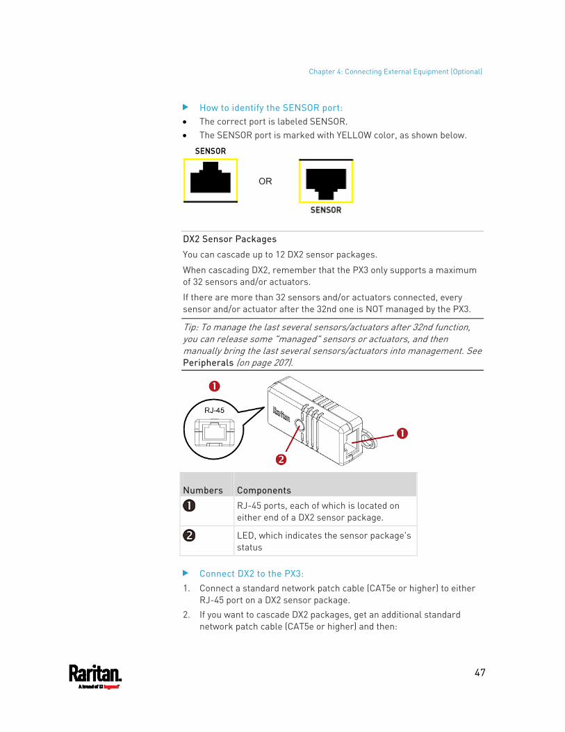
Chapter 4: Connecting External Equipment (Optional)
47
How to identify the SENSOR port: The correct port is labeled SENSOR. The SENSOR port is marked with YELLOW color, as shown below.
DX2 Sensor Packages
You can cascade up to 12 DX2 sensor packages.
When cascading DX2, remember that the PX3 only supports a maximum of 32 sensors and/or actuators.
If there are more than 32 sensors and/or actuators connected, every sensor and/or actuator after the 32nd one is NOT managed by the PX3.
Tip: To manage the last several sensors/actuators after 32nd function, you can release some "managed" sensors or actuators, and then manually bring the last several sensors/actuators into management. See Peripherals (on page 207).
Numbers Components
RJ-45 ports, each of which is located on either end of a DX2 sensor package.
LED, which indicates the sensor package's status
Connect DX2 to the PX3: 1. Connect a standard network patch cable (CAT5e or higher) to either
RJ-45 port on a DX2 sensor package. 2. If you want to cascade DX2 packages, get an additional standard
network patch cable (CAT5e or higher) and then:
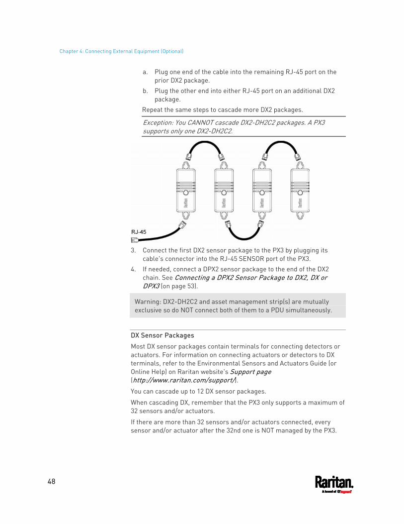
Chapter 4: Connecting External Equipment (Optional)
48
a. Plug one end of the cable into the remaining RJ-45 port on the prior DX2 package.
b. Plug the other end into either RJ-45 port on an additional DX2 package.
Repeat the same steps to cascade more DX2 packages.
Exception: You CANNOT cascade DX2-DH2C2 packages. A PX3 supports only one DX2-DH2C2.
3. Connect the first DX2 sensor package to the PX3 by plugging its
cable's connector into the RJ-45 SENSOR port of the PX3. 4. If needed, connect a DPX2 sensor package to the end of the DX2
chain. See Connecting a DPX2 Sensor Package to DX2, DX or DPX3 (on page 53).
Warning: DX2-DH2C2 and asset management strip(s) are mutually exclusive so do NOT connect both of them to a PDU simultaneously.
DX Sensor Packages
Most DX sensor packages contain terminals for connecting detectors or actuators. For information on connecting actuators or detectors to DX terminals, refer to the Environmental Sensors and Actuators Guide (or Online Help) on Raritan website's Support page (http://www.raritan.com/support/).
You can cascade up to 12 DX sensor packages.
When cascading DX, remember that the PX3 only supports a maximum of 32 sensors and/or actuators.
If there are more than 32 sensors and/or actuators connected, every sensor and/or actuator after the 32nd one is NOT managed by the PX3.
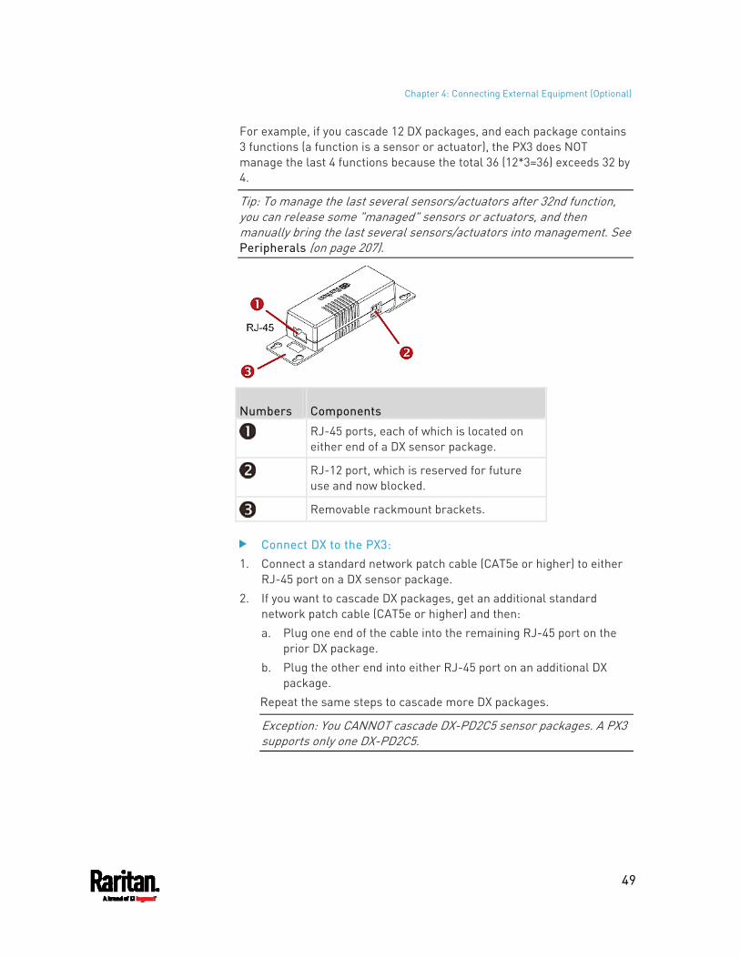
Chapter 4: Connecting External Equipment (Optional)
49
For example, if you cascade 12 DX packages, and each package contains 3 functions (a function is a sensor or actuator), the PX3 does NOT manage the last 4 functions because the total 36 (12*3=36) exceeds 32 by 4.
Tip: To manage the last several sensors/actuators after 32nd function, you can release some "managed" sensors or actuators, and then manually bring the last several sensors/actuators into management. See Peripherals (on page 207).
Numbers Components
RJ-45 ports, each of which is located on either end of a DX sensor package.
RJ-12 port, which is reserved for future use and now blocked.
Removable rackmount brackets.
Connect DX to the PX3: 1. Connect a standard network patch cable (CAT5e or higher) to either
RJ-45 port on a DX sensor package. 2. If you want to cascade DX packages, get an additional standard
network patch cable (CAT5e or higher) and then: a. Plug one end of the cable into the remaining RJ-45 port on the
prior DX package. b. Plug the other end into either RJ-45 port on an additional DX
package. Repeat the same steps to cascade more DX packages.
Exception: You CANNOT cascade DX-PD2C5 sensor packages. A PX3 supports only one DX-PD2C5.
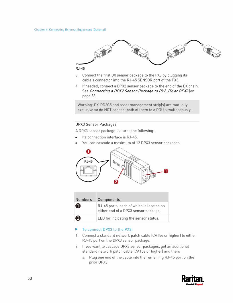
Chapter 4: Connecting External Equipment (Optional)
50
3. Connect the first DX sensor package to the PX3 by plugging its
cable's connector into the RJ-45 SENSOR port of the PX3. 4. If needed, connect a DPX2 sensor package to the end of the DX chain.
See Connecting a DPX2 Sensor Package to DX2, DX or DPX3 (on page 53).
Warning: DX-PD2C5 and asset management strip(s) are mutually exclusive so do NOT connect both of them to a PDU simultaneously.
DPX3 Sensor Packages
A DPX3 sensor package features the following:
Its connection interface is RJ-45. You can cascade a maximum of 12 DPX3 sensor packages.
Numbers Components
RJ-45 ports, each of which is located on either end of a DPX3 sensor package.
LED for indicating the sensor status.
To connect DPX3 to the PX3: 1. Connect a standard network patch cable (CAT5e or higher) to either
RJ-45 port on the DPX3 sensor package. 2. If you want to cascade DPX3 sensor packages, get an additional
standard network patch cable (CAT5e or higher) and then: a. Plug one end of the cable into the remaining RJ-45 port on the
prior DPX3.
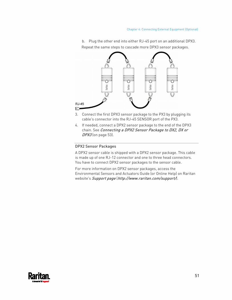
Chapter 4: Connecting External Equipment (Optional)
51
b. Plug the other end into either RJ-45 port on an additional DPX3. Repeat the same steps to cascade more DPX3 sensor packages.
3. Connect the first DPX3 sensor package to the PX3 by plugging its
cable's connector into the RJ-45 SENSOR port of the PX3. 4. If needed, connect a DPX2 sensor package to the end of the DPX3
chain. See Connecting a DPX2 Sensor Package to DX2, DX or DPX3 (on page 53).
DPX2 Sensor Packages
A DPX2 sensor cable is shipped with a DPX2 sensor package. This cable is made up of one RJ-12 connector and one to three head connectors. You have to connect DPX2 sensor packages to the sensor cable.
For more information on DPX2 sensor packages, access the Environmental Sensors and Actuators Guide (or Online Help) on Raritan website's Support page (http://www.raritan.com/support/).
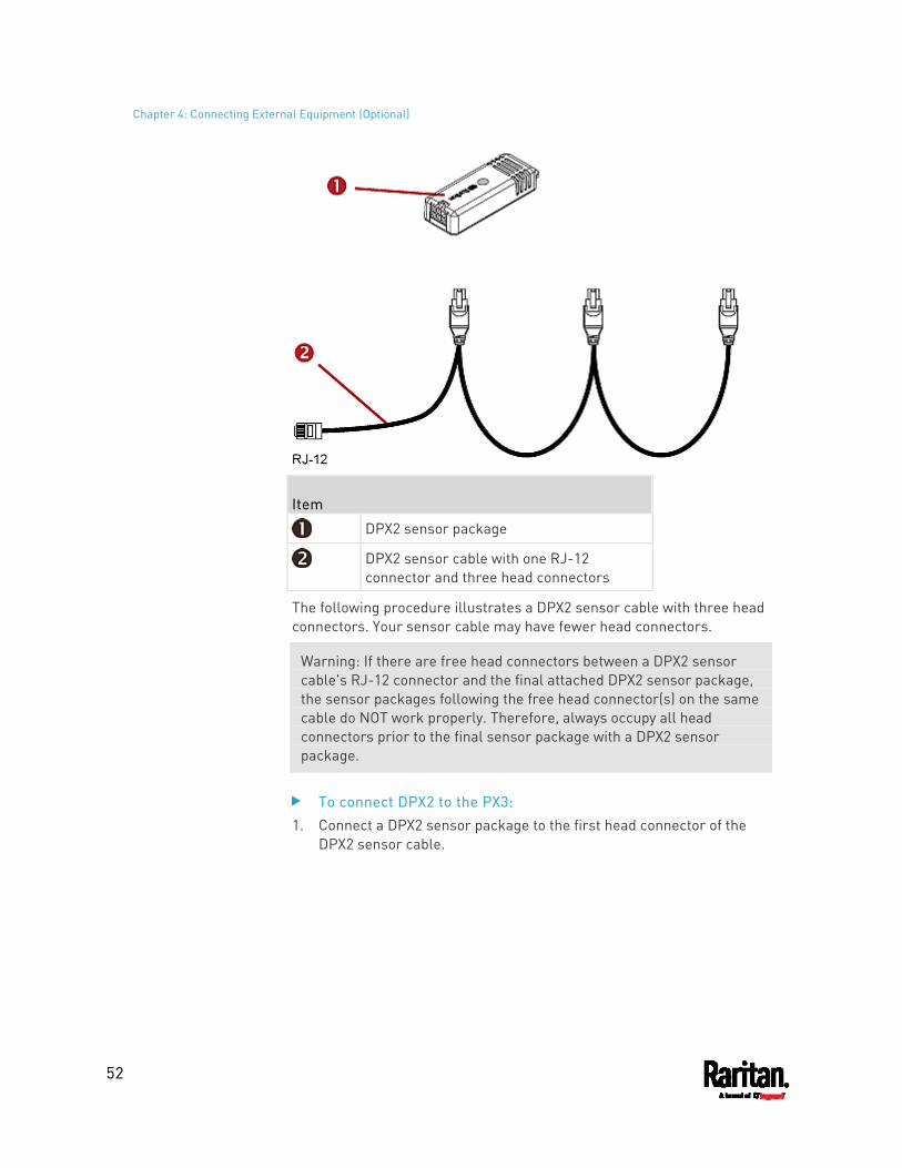
Chapter 4: Connecting External Equipment (Optional)
52
Item
DPX2 sensor package
DPX2 sensor cable with one RJ-12 connector and three head connectors
The following procedure illustrates a DPX2 sensor cable with three head connectors. Your sensor cable may have fewer head connectors.
Warning: If there are free head connectors between a DPX2 sensor cable's RJ-12 connector and the final attached DPX2 sensor package, the sensor packages following the free head connector(s) on the same cable do NOT work properly. Therefore, always occupy all head connectors prior to the final sensor package with a DPX2 sensor package.
To connect DPX2 to the PX3: 1. Connect a DPX2 sensor package to the first head connector of the
DPX2 sensor cable.
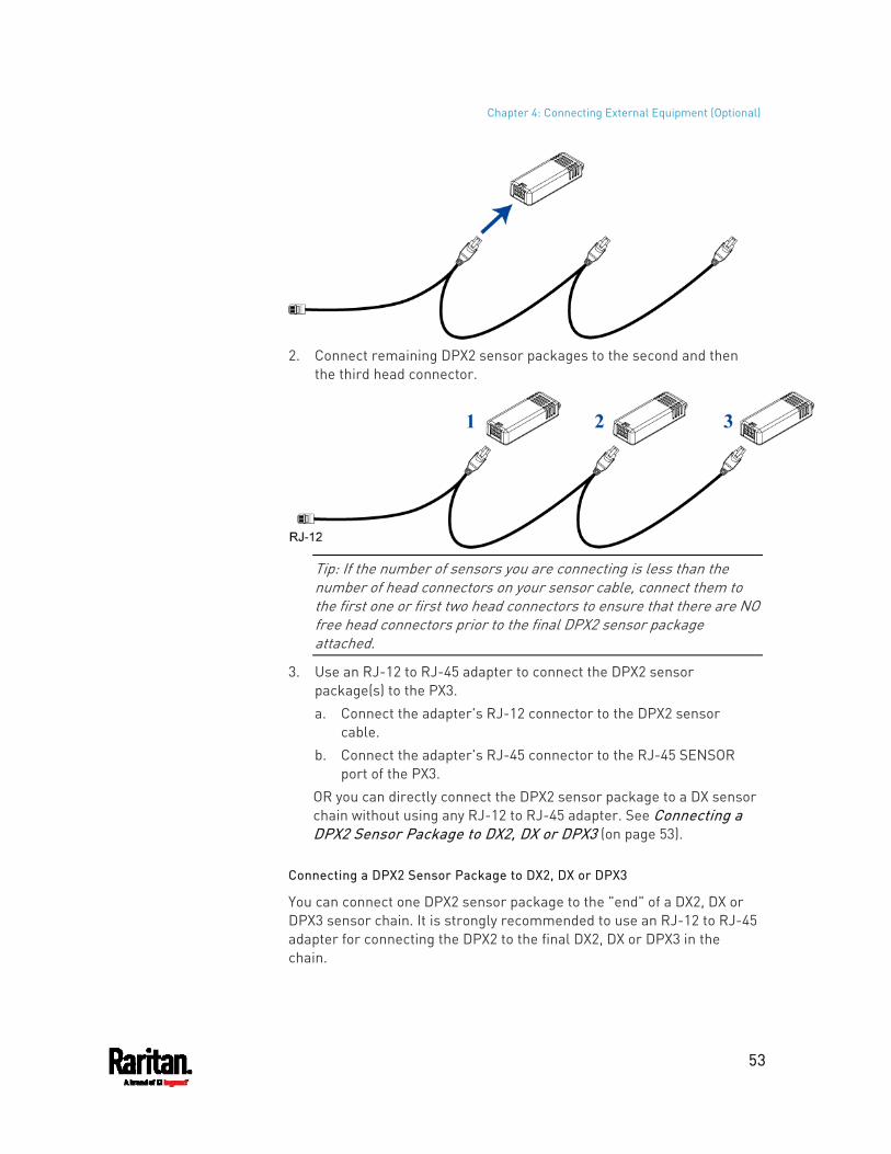
Chapter 4: Connecting External Equipment (Optional)
53
2. Connect remaining DPX2 sensor packages to the second and then
the third head connector.
Tip: If the number of sensors you are connecting is less than the number of head connectors on your sensor cable, connect them to the first one or first two head connectors to ensure that there are NO free head connectors prior to the final DPX2 sensor package attached.
3. Use an RJ-12 to RJ-45 adapter to connect the DPX2 sensor package(s) to the PX3. a. Connect the adapter's RJ-12 connector to the DPX2 sensor
cable. b. Connect the adapter's RJ-45 connector to the RJ-45 SENSOR
port of the PX3. OR you can directly connect the DPX2 sensor package to a DX sensor chain without using any RJ-12 to RJ-45 adapter. See Connecting a DPX2 Sensor Package to DX2, DX or DPX3 (on page 53).
Connecting a DPX2 Sensor Package to DX2, DX or DPX3
You can connect one DPX2 sensor package to the "end" of a DX2, DX or DPX3 sensor chain. It is strongly recommended to use an RJ-12 to RJ-45 adapter for connecting the DPX2 to the final DX2, DX or DPX3 in the chain.
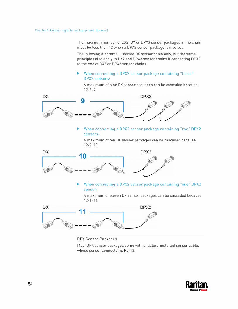
Chapter 4: Connecting External Equipment (Optional)
54
The maximum number of DX2, DX or DPX3 sensor packages in the chain must be less than 12 when a DPX2 sensor package is involved.
The following diagrams illustrate DX sensor chain only, but the same principles also apply to DX2 and DPX3 sensor chains if connecting DPX2 to the end of DX2 or DPX3 sensor chains.
When connecting a DPX2 sensor package containing "three" DPX2 sensors: A maximum of nine DX sensor packages can be cascaded because 12-3=9.
When connecting a DPX2 sensor package containing "two" DPX2 sensors: A maximum of ten DX sensor packages can be cascaded because 12-2=10.
When connecting a DPX2 sensor package containing "one" DPX2 sensor: A maximum of eleven DX sensor packages can be cascaded because 12-1=11.
DPX Sensor Packages
Most DPX sensor packages come with a factory-installed sensor cable, whose sensor connector is RJ-12.
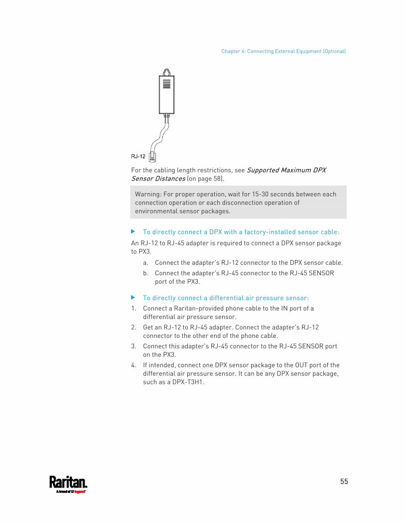
Chapter 4: Connecting External Equipment (Optional)
55
For the cabling length restrictions, see Supported Maximum DPX Sensor Distances (on page 58).
Warning: For proper operation, wait for 15-30 seconds between each connection operation or each disconnection operation of environmental sensor packages.
To directly connect a DPX with a factory-installed sensor cable:
An RJ-12 to RJ-45 adapter is required to connect a DPX sensor package to PX3.
a. Connect the adapter's RJ-12 connector to the DPX sensor cable. b. Connect the adapter's RJ-45 connector to the RJ-45 SENSOR
port of the PX3.
To directly connect a differential air pressure sensor: 1. Connect a Raritan-provided phone cable to the IN port of a
differential air pressure sensor. 2. Get an RJ-12 to RJ-45 adapter. Connect the adapter's RJ-12
connector to the other end of the phone cable. 3. Connect this adapter's RJ-45 connector to the RJ-45 SENSOR port
on the PX3. 4. If intended, connect one DPX sensor package to the OUT port of the
differential air pressure sensor. It can be any DPX sensor package, such as a DPX-T3H1.
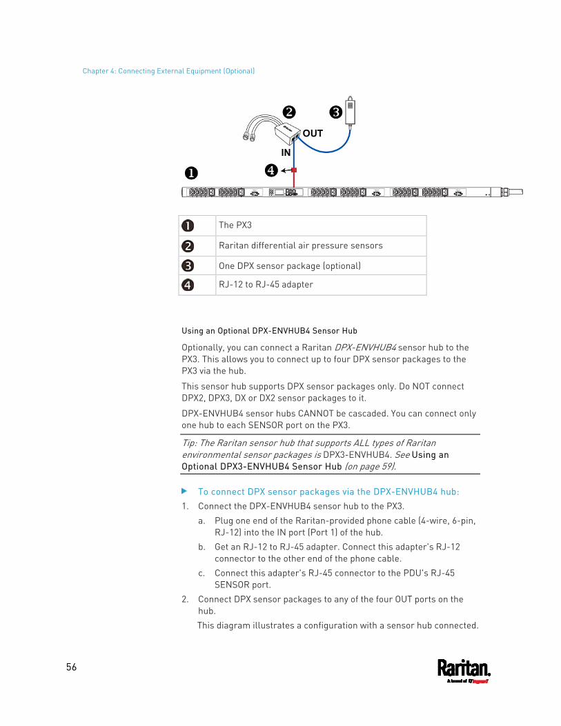
Chapter 4: Connecting External Equipment (Optional)
56
The PX3
Raritan differential air pressure sensors
One DPX sensor package (optional)
RJ-12 to RJ-45 adapter
Using an Optional DPX-ENVHUB4 Sensor Hub
Optionally, you can connect a Raritan DPX-ENVHUB4 sensor hub to the PX3. This allows you to connect up to four DPX sensor packages to the PX3 via the hub.
This sensor hub supports DPX sensor packages only. Do NOT connect DPX2, DPX3, DX or DX2 sensor packages to it.
DPX-ENVHUB4 sensor hubs CANNOT be cascaded. You can connect only one hub to each SENSOR port on the PX3.
Tip: The Raritan sensor hub that supports ALL types of Raritan environmental sensor packages is DPX3-ENVHUB4. See Using an Optional DPX3-ENVHUB4 Sensor Hub (on page 59).
To connect DPX sensor packages via the DPX-ENVHUB4 hub: 1. Connect the DPX-ENVHUB4 sensor hub to the PX3.
a. Plug one end of the Raritan-provided phone cable (4-wire, 6-pin, RJ-12) into the IN port (Port 1) of the hub.
b. Get an RJ-12 to RJ-45 adapter. Connect this adapter's RJ-12 connector to the other end of the phone cable.
c. Connect this adapter's RJ-45 connector to the PDU's RJ-45 SENSOR port.
2. Connect DPX sensor packages to any of the four OUT ports on the hub. This diagram illustrates a configuration with a sensor hub connected.
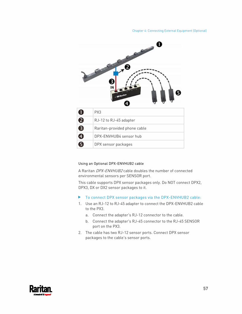
Chapter 4: Connecting External Equipment (Optional)
57
PX3
RJ-12 to RJ-45 adapter
Raritan-provided phone cable
DPX-ENVHUB4 sensor hub
DPX sensor packages
Using an Optional DPX-ENVHUB2 cable
A Raritan DPX-ENVHUB2 cable doubles the number of connected environmental sensors per SENSOR port.
This cable supports DPX sensor packages only. Do NOT connect DPX2, DPX3, DX or DX2 sensor packages to it.
To connect DPX sensor packages via the DPX-ENVHUB2 cable: 1. Use an RJ-12 to RJ-45 adapter to connect the DPX-ENVHUB2 cable
to the PX3. a. Connect the adapter's RJ-12 connector to the cable. b. Connect the adapter's RJ-45 connector to the RJ-45 SENSOR
port on the PX3. 2. The cable has two RJ-12 sensor ports. Connect DPX sensor
packages to the cable's sensor ports.
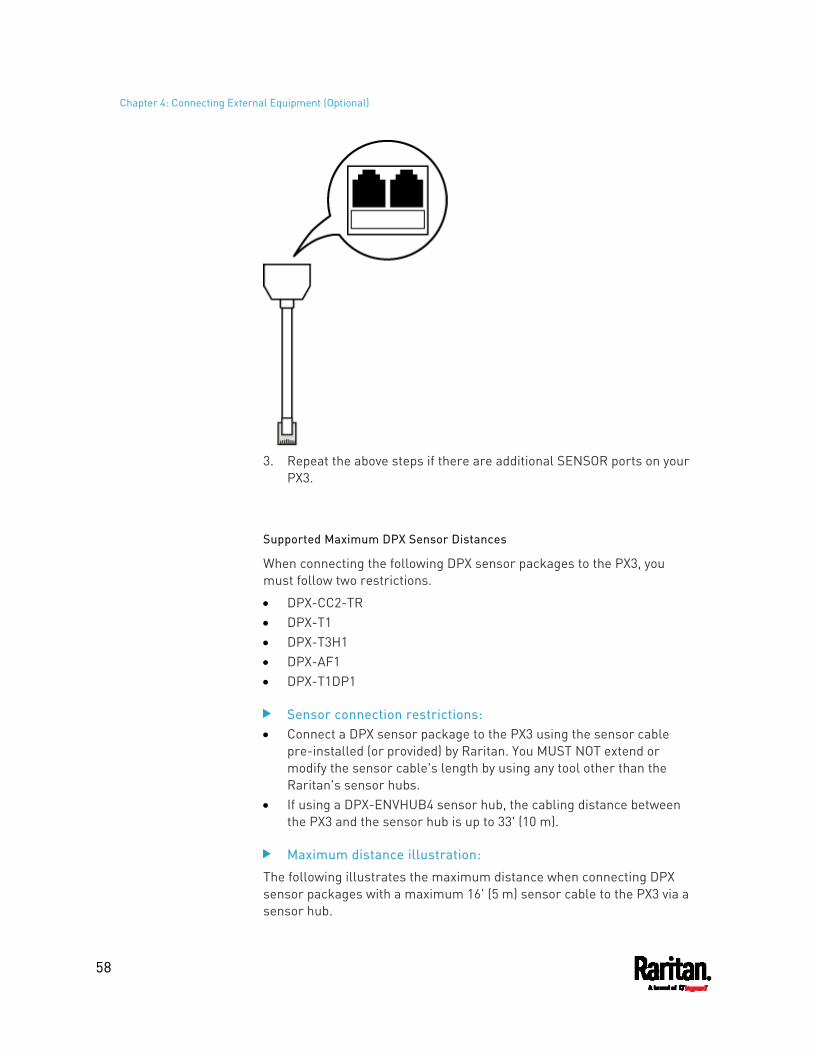
Chapter 4: Connecting External Equipment (Optional)
58
3. Repeat the above steps if there are additional SENSOR ports on your
PX3.
Supported Maximum DPX Sensor Distances
When connecting the following DPX sensor packages to the PX3, you must follow two restrictions.
DPX-CC2-TR DPX-T1 DPX-T3H1 DPX-AF1 DPX-T1DP1
Sensor connection restrictions: Connect a DPX sensor package to the PX3 using the sensor cable
pre-installed (or provided) by Raritan. You MUST NOT extend or modify the sensor cable's length by using any tool other than the Raritan's sensor hubs.
If using a DPX-ENVHUB4 sensor hub, the cabling distance between the PX3 and the sensor hub is up to 33' (10 m).
Maximum distance illustration:
The following illustrates the maximum distance when connecting DPX sensor packages with a maximum 16' (5 m) sensor cable to the PX3 via a sensor hub.
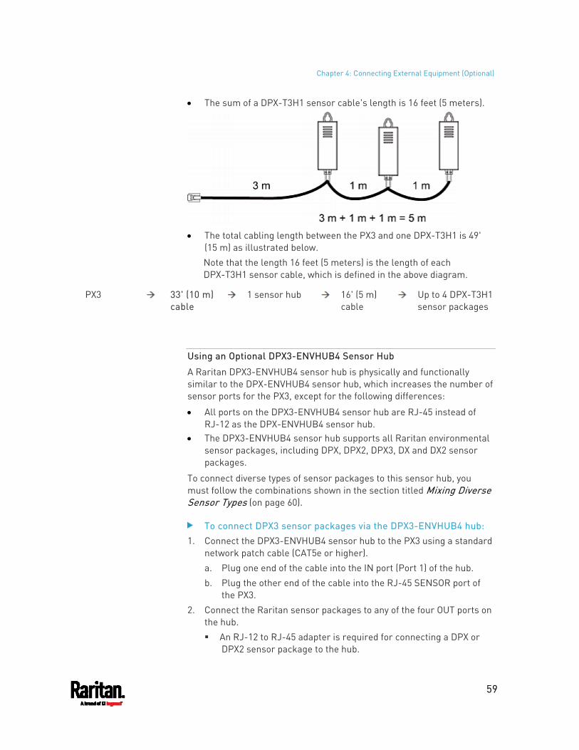
Chapter 4: Connecting External Equipment (Optional)
59
The sum of a DPX-T3H1 sensor cable's length is 16 feet (5 meters).
The total cabling length between the PX3 and one DPX-T3H1 is 49'
(15 m) as illustrated below. Note that the length 16 feet (5 meters) is the length of each DPX-T3H1 sensor cable, which is defined in the above diagram.
PX3 33' (10 m) cable
1 sensor hub 16' (5 m) cable
Up to 4 DPX-T3H1 sensor packages
Using an Optional DPX3-ENVHUB4 Sensor Hub
A Raritan DPX3-ENVHUB4 sensor hub is physically and functionally similar to the DPX-ENVHUB4 sensor hub, which increases the number of sensor ports for the PX3, except for the following differences:
All ports on the DPX3-ENVHUB4 sensor hub are RJ-45 instead of RJ-12 as the DPX-ENVHUB4 sensor hub.
The DPX3-ENVHUB4 sensor hub supports all Raritan environmental sensor packages, including DPX, DPX2, DPX3, DX and DX2 sensor packages.
To connect diverse types of sensor packages to this sensor hub, you must follow the combinations shown in the section titled Mixing Diverse Sensor Types (on page 60).
To connect DPX3 sensor packages via the DPX3-ENVHUB4 hub: 1. Connect the DPX3-ENVHUB4 sensor hub to the PX3 using a standard
network patch cable (CAT5e or higher). a. Plug one end of the cable into the IN port (Port 1) of the hub. b. Plug the other end of the cable into the RJ-45 SENSOR port of
the PX3. 2. Connect the Raritan sensor packages to any of the four OUT ports on
the hub. An RJ-12 to RJ-45 adapter is required for connecting a DPX or
DPX2 sensor package to the hub.
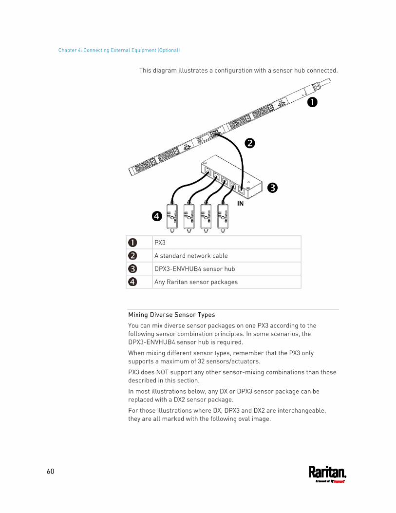
Chapter 4: Connecting External Equipment (Optional)
60
This diagram illustrates a configuration with a sensor hub connected.
PX3
A standard network cable
DPX3-ENVHUB4 sensor hub
Any Raritan sensor packages
Mixing Diverse Sensor Types
You can mix diverse sensor packages on one PX3 according to the following sensor combination principles. In some scenarios, the DPX3-ENVHUB4 sensor hub is required.
When mixing different sensor types, remember that the PX3 only supports a maximum of 32 sensors/actuators.
PX3 does NOT support any other sensor-mixing combinations than those described in this section.
In most illustrations below, any DX or DPX3 sensor package can be replaced with a DX2 sensor package.
For those illustrations where DX, DPX3 and DX2 are interchangeable, they are all marked with the following oval image.
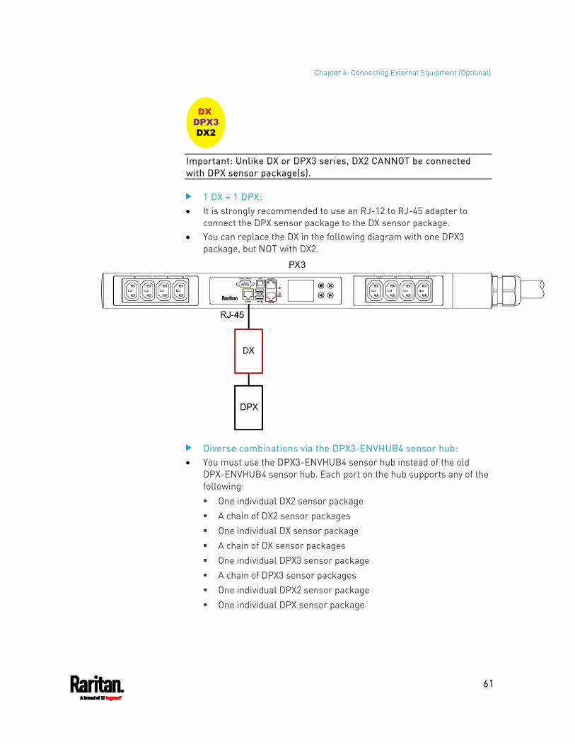
Chapter 4: Connecting External Equipment (Optional)
61
Important: Unlike DX or DPX3 series, DX2 CANNOT be connected with DPX sensor package(s).
1 DX + 1 DPX: It is strongly recommended to use an RJ-12 to RJ-45 adapter to
connect the DPX sensor package to the DX sensor package. You can replace the DX in the following diagram with one DPX3
package, but NOT with DX2.
Diverse combinations via the DPX3-ENVHUB4 sensor hub: You must use the DPX3-ENVHUB4 sensor hub instead of the old
DPX-ENVHUB4 sensor hub. Each port on the hub supports any of the following: One individual DX2 sensor package A chain of DX2 sensor packages One individual DX sensor package A chain of DX sensor packages One individual DPX3 sensor package A chain of DPX3 sensor packages One individual DPX2 sensor package One individual DPX sensor package
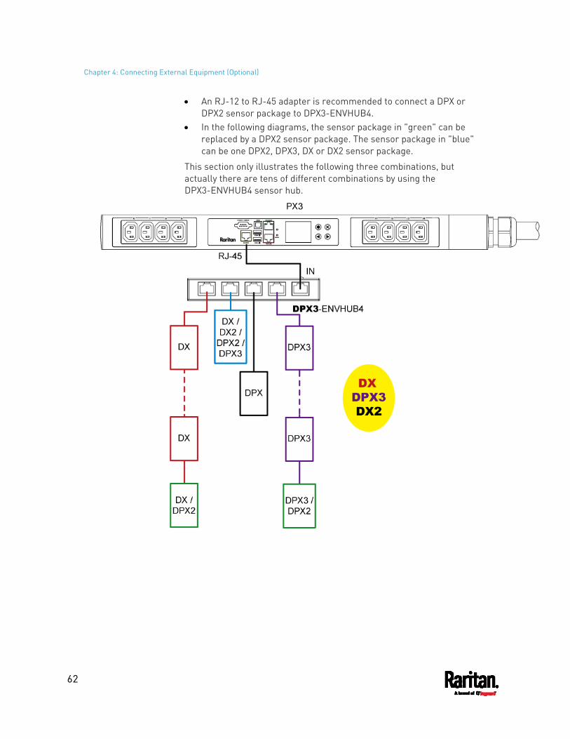
Chapter 4: Connecting External Equipment (Optional)
62
An RJ-12 to RJ-45 adapter is recommended to connect a DPX or DPX2 sensor package to DPX3-ENVHUB4.
In the following diagrams, the sensor package in "green" can be replaced by a DPX2 sensor package. The sensor package in "blue" can be one DPX2, DPX3, DX or DX2 sensor package.
This section only illustrates the following three combinations, but actually there are tens of different combinations by using the DPX3-ENVHUB4 sensor hub.
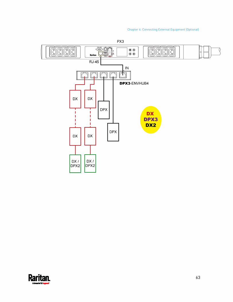
Chapter 4: Connecting External Equipment (Optional)
63
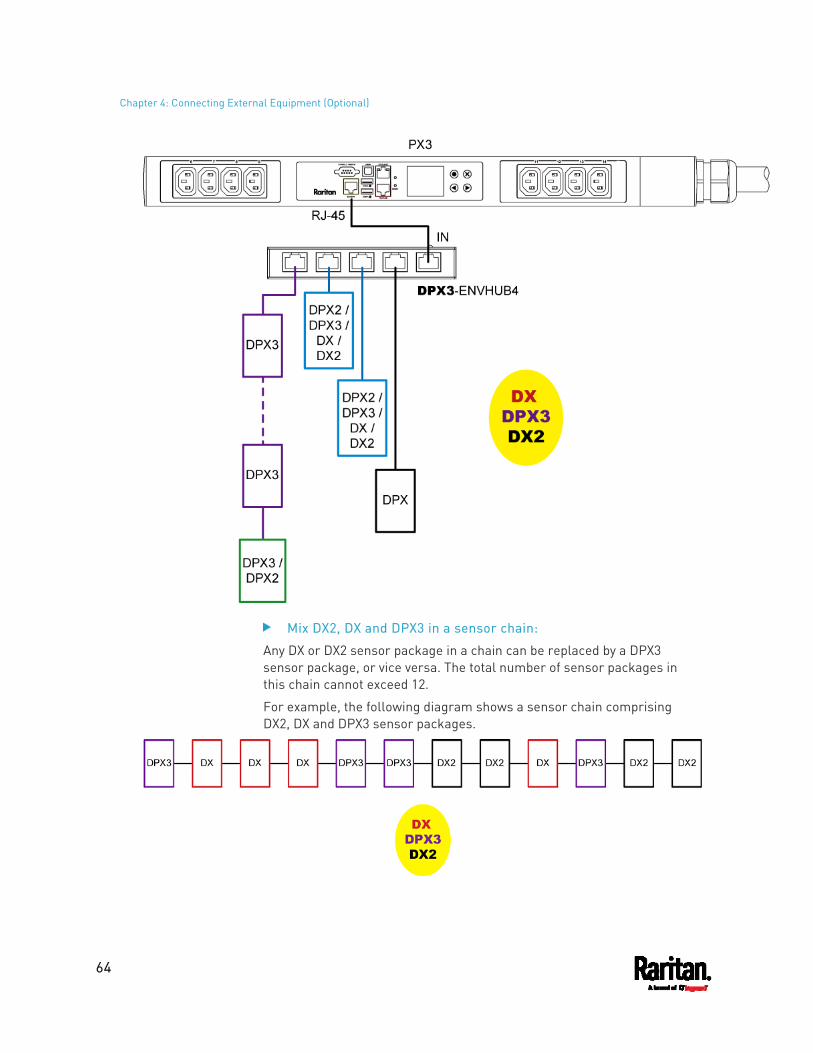
Chapter 4: Connecting External Equipment (Optional)
64
Mix DX2, DX and DPX3 in a sensor chain:
Any DX or DX2 sensor package in a chain can be replaced by a DPX3 sensor package, or vice versa. The total number of sensor packages in this chain cannot exceed 12.
For example, the following diagram shows a sensor chain comprising DX2, DX and DPX3 sensor packages.
Chapter 4: Connecting External Equipment (Optional)
65
You can add a DPX2 sensor package to the end of such a sensor-mixing chain if needed. See Connecting a DPX2 Sensor Package to DX2, DX or DPX3 (on page 53).
Connecting Asset Management Strips
You can remotely track the locations of up to 64 IT devices in the rack by connecting asset management strips (asset strips) to the PX3 after IT devices are tagged electronically.
To use the asset management feature, you need the following items:
Raritan asset strips: An asset strip transmits the asset management tag's ID and positioning information to the PX3.
Raritan asset tags: An asset management tag (asset tag) is adhered to an IT device. The asset tag uses an electronic ID to identify and locate the IT device.
Warning: DX-PD2C5 and asset management strip(s) are mutually exclusive so do NOT connect both of them to a PDU simultaneously.
Combining Regular Asset Strips
Each tag port on the regular asset strips corresponds to a rack unit and can be used to locate IT devices in a specific rack (or cabinet).
For each rack, you can attach asset strips up to 64U long, consisting of one MASTER and multiple SLAVE asset strips.
The difference between the master and slave asset strips is that the master asset strip has an RJ-45 connector while the slave does not.
The following diagram illustrates some asset strips. Note that Raritan provides more types of asset strips than the diagram.
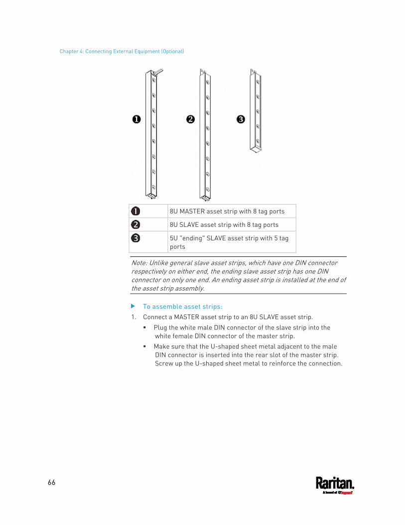
Chapter 4: Connecting External Equipment (Optional)
66
8U MASTER asset strip with 8 tag ports
8U SLAVE asset strip with 8 tag ports
5U "ending" SLAVE asset strip with 5 tag ports
Note: Unlike general slave asset strips, which have one DIN connector respectively on either end, the ending slave asset strip has one DIN connector on only one end. An ending asset strip is installed at the end of the asset strip assembly.
To assemble asset strips: 1. Connect a MASTER asset strip to an 8U SLAVE asset strip.
Plug the white male DIN connector of the slave strip into the white female DIN connector of the master strip.
Make sure that the U-shaped sheet metal adjacent to the male DIN connector is inserted into the rear slot of the master strip. Screw up the U-shaped sheet metal to reinforce the connection.
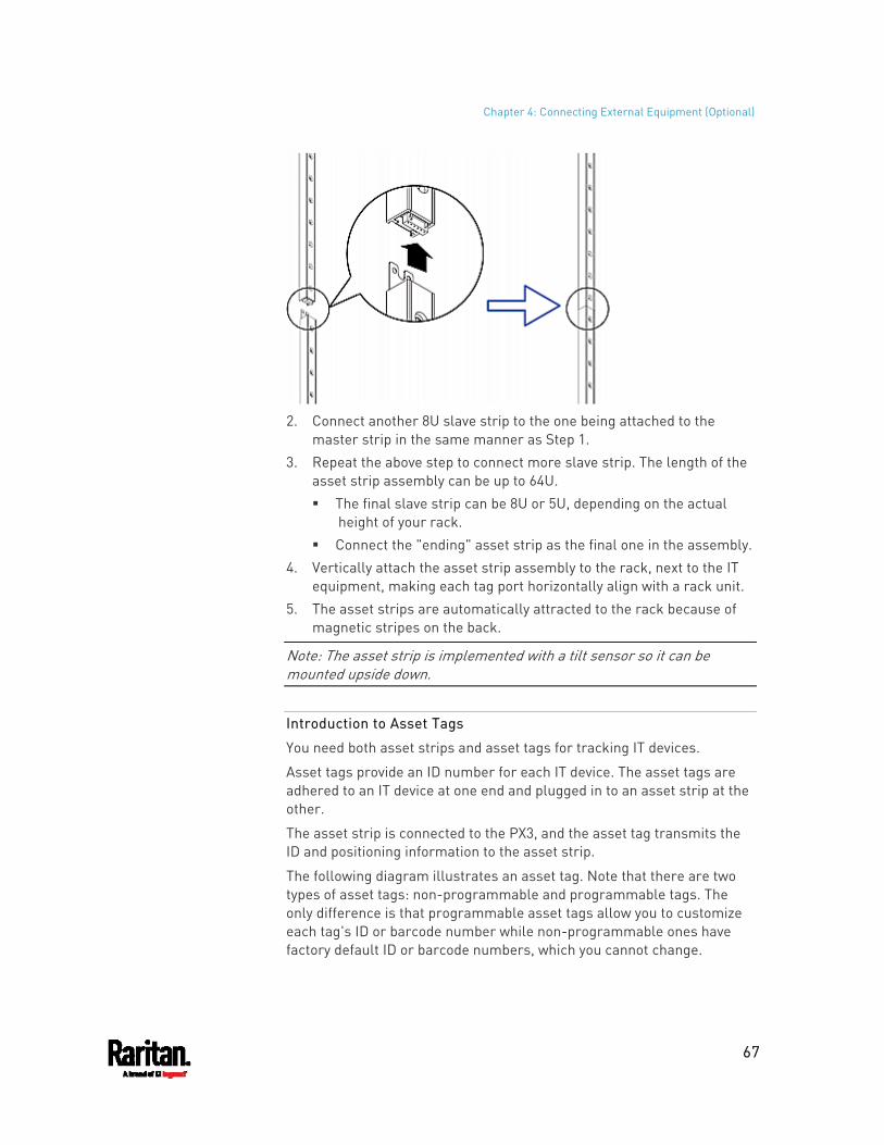
Chapter 4: Connecting External Equipment (Optional)
67
2. Connect another 8U slave strip to the one being attached to the
master strip in the same manner as Step 1. 3. Repeat the above step to connect more slave strip. The length of the
asset strip assembly can be up to 64U. The final slave strip can be 8U or 5U, depending on the actual
height of your rack. Connect the "ending" asset strip as the final one in the assembly.
4. Vertically attach the asset strip assembly to the rack, next to the IT equipment, making each tag port horizontally align with a rack unit.
5. The asset strips are automatically attracted to the rack because of magnetic stripes on the back.
Note: The asset strip is implemented with a tilt sensor so it can be mounted upside down.
Introduction to Asset Tags
You need both asset strips and asset tags for tracking IT devices.
Asset tags provide an ID number for each IT device. The asset tags are adhered to an IT device at one end and plugged in to an asset strip at the other.
The asset strip is connected to the PX3, and the asset tag transmits the ID and positioning information to the asset strip.
The following diagram illustrates an asset tag. Note that there are two types of asset tags: non-programmable and programmable tags. The only difference is that programmable asset tags allow you to customize each tag's ID or barcode number while non-programmable ones have factory default ID or barcode numbers, which you cannot change.
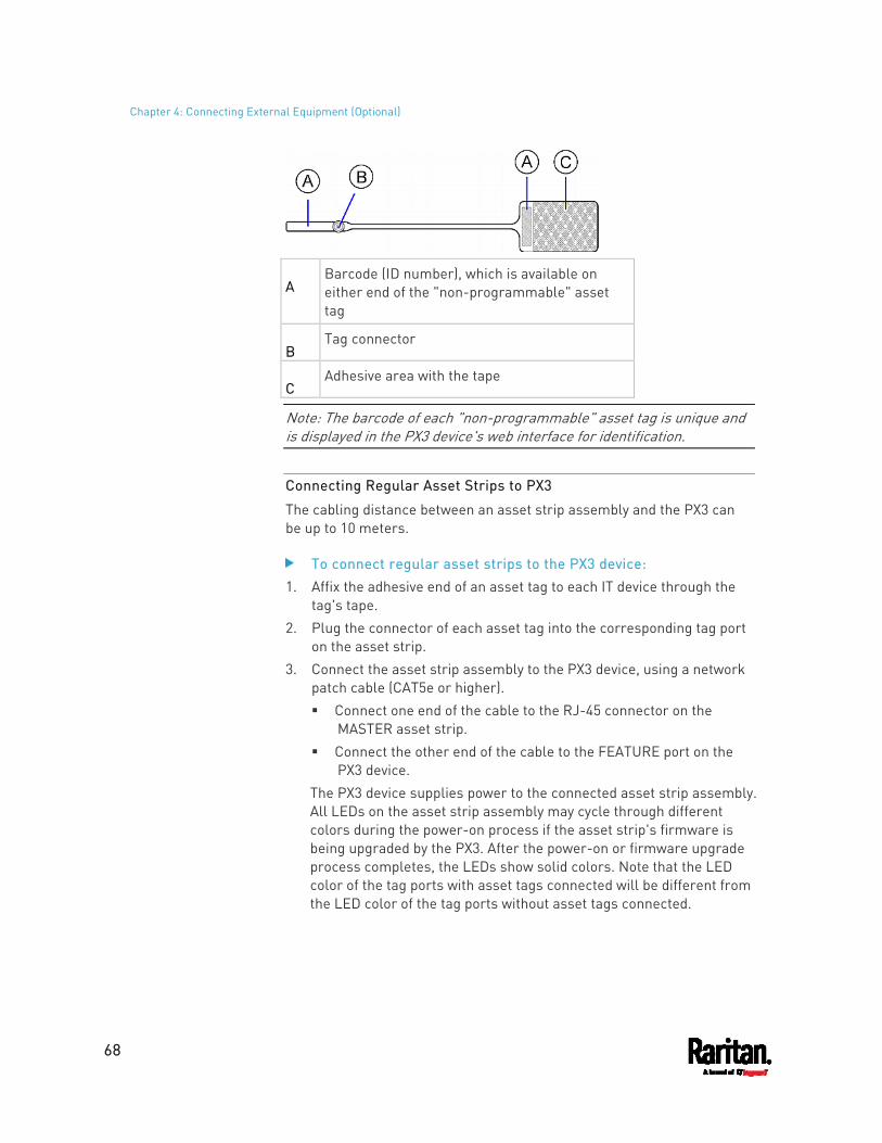
Chapter 4: Connecting External Equipment (Optional)
68
A Barcode (ID number), which is available on either end of the "non-programmable" asset tag
B Tag connector
C Adhesive area with the tape
Note: The barcode of each "non-programmable" asset tag is unique and is displayed in the PX3 device's web interface for identification.
Connecting Regular Asset Strips to PX3
The cabling distance between an asset strip assembly and the PX3 can be up to 10 meters.
To connect regular asset strips to the PX3 device: 1. Affix the adhesive end of an asset tag to each IT device through the
tag's tape. 2. Plug the connector of each asset tag into the corresponding tag port
on the asset strip. 3. Connect the asset strip assembly to the PX3 device, using a network
patch cable (CAT5e or higher). Connect one end of the cable to the RJ-45 connector on the
MASTER asset strip. Connect the other end of the cable to the FEATURE port on the
PX3 device. The PX3 device supplies power to the connected asset strip assembly. All LEDs on the asset strip assembly may cycle through different colors during the power-on process if the asset strip's firmware is being upgraded by the PX3. After the power-on or firmware upgrade process completes, the LEDs show solid colors. Note that the LED color of the tag ports with asset tags connected will be different from the LED color of the tag ports without asset tags connected.
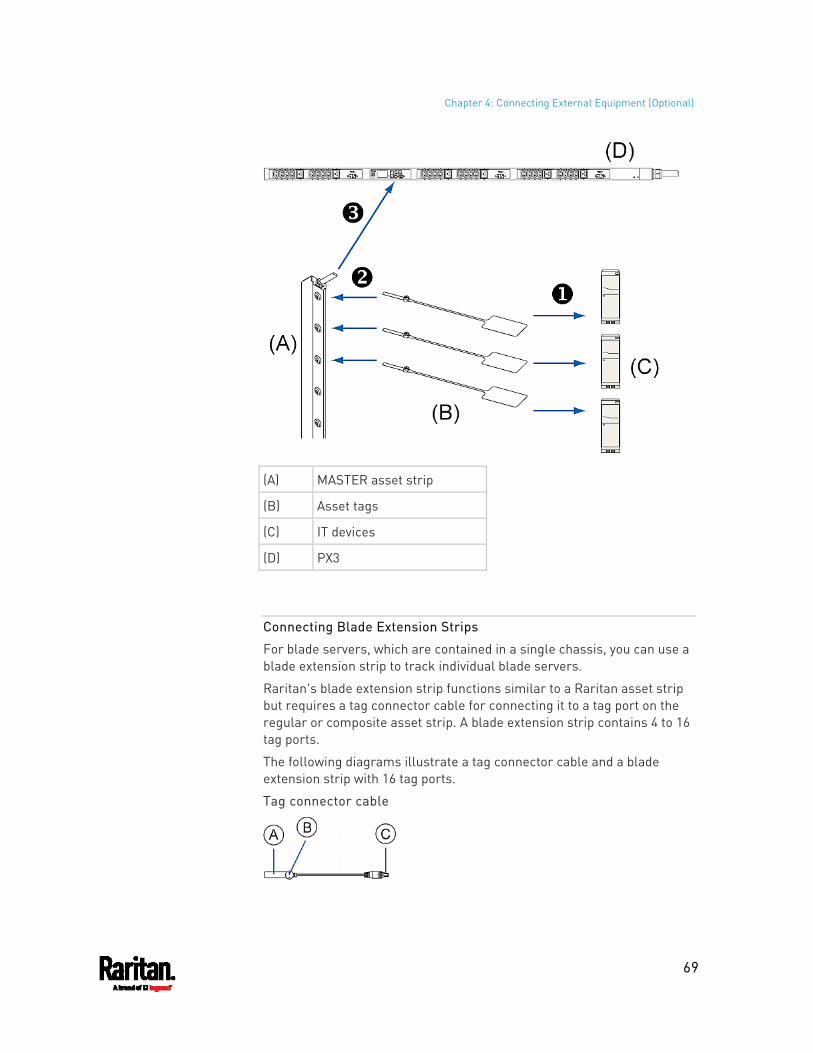
Chapter 4: Connecting External Equipment (Optional)
69
(A) MASTER asset strip
(B) Asset tags
(C) IT devices
(D) PX3
Connecting Blade Extension Strips
For blade servers, which are contained in a single chassis, you can use a blade extension strip to track individual blade servers.
Raritan's blade extension strip functions similar to a Raritan asset strip but requires a tag connector cable for connecting it to a tag port on the regular or composite asset strip. A blade extension strip contains 4 to 16 tag ports.
The following diagrams illustrate a tag connector cable and a blade extension strip with 16 tag ports.
Tag connector cable
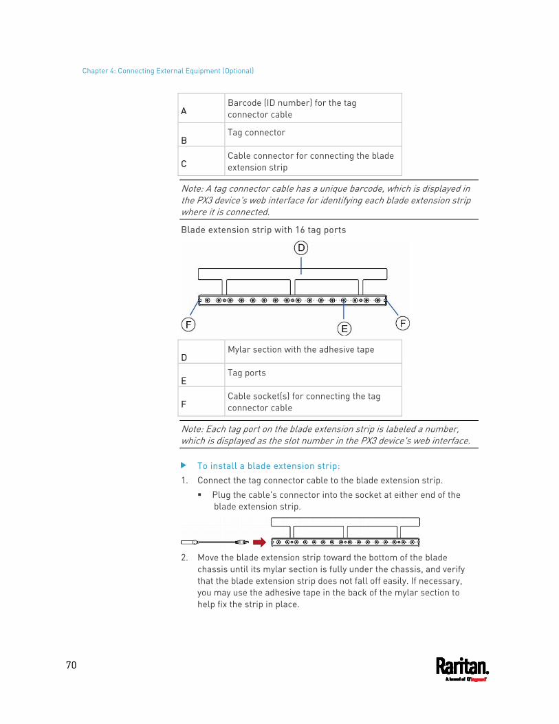
Chapter 4: Connecting External Equipment (Optional)
70
A Barcode (ID number) for the tag connector cable
B Tag connector
C Cable connector for connecting the blade extension strip
Note: A tag connector cable has a unique barcode, which is displayed in the PX3 device's web interface for identifying each blade extension strip where it is connected.
Blade extension strip with 16 tag ports
D Mylar section with the adhesive tape
E Tag ports
F Cable socket(s) for connecting the tag connector cable
Note: Each tag port on the blade extension strip is labeled a number, which is displayed as the slot number in the PX3 device's web interface.
To install a blade extension strip: 1. Connect the tag connector cable to the blade extension strip.
Plug the cable's connector into the socket at either end of the blade extension strip.
2. Move the blade extension strip toward the bottom of the blade
chassis until its mylar section is fully under the chassis, and verify that the blade extension strip does not fall off easily. If necessary, you may use the adhesive tape in the back of the mylar section to help fix the strip in place.
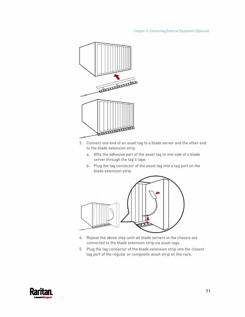
Chapter 4: Connecting External Equipment (Optional)
71
3. Connect one end of an asset tag to a blade server and the other end
to the blade extension strip. a. Affix the adhesive part of the asset tag to one side of a blade
server through the tag's tape. b. Plug the tag connector of the asset tag into a tag port on the
blade extension strip.
4. Repeat the above step until all blade servers in the chassis are
connected to the blade extension strip via asset tags. 5. Plug the tag connector of the blade extension strip into the closest
tag port of the regular or composite asset strip on the rack.

Chapter 4: Connecting External Equipment (Optional)
72
6. Repeat the above steps to connect additional blade extension strips.
Up to 128 asset tags on blade extension strips are supported per FEATURE port.
Note: If you need to temporarily disconnect the blade extension strip from the asset strip, wait at least 1 second before re-connecting it back, or the PX3 device may not detect it.
Connecting Composite Asset Strips (AMS-Mx-Z)
A composite asset strip is named AMS-Mx-Z, where x is a number, such as AMS-M2-Z or AMS-M3-Z. It is a type of asset strip that functions the same as regular MASTER asset strips except for the following differences:
It has two RJ-45 connectors. Multiple composite asset strips can be daisy chained. It contains less tag ports than regular asset strips.
For example, AMS-M2-Z contains two tag ports, and AMS-M3-Z contains three tag ports only.
The composite asset strip is especially useful for tracking large devices such as SAN boxes in the cabinet.
The following diagram illustrates AMS-M3-Z.
Chapter 4: Connecting External Equipment (Optional)
73
A Two RJ-45 connectors
B Tag ports
Important: DO NOT hot swap or hot plug any AMS-Mx-Z in a composite asset strip chain after connecting the chain to the PX3 device. Doing so may cause the device's FEATURE port to malfunction.
To connect composite asset strips to the PX3 device:
If there are only 2 or 3 IT devices to track, you can connect only one AMS-M2-Z or AMS-M3-Z to the PX3 device. In this case, go to step 2. If there are more than 2 or 3 IT devices, you need to daisy chain multiple composite asset strips and start from step 1.
1. (Optional) Daisy chain multiple composite asset strips. a. Get a standard network patch cable that is within 2 meters. b. Connect one end of the network cable to the RJ-45 connector
labeled "Output" on the first composite asset strip. c. Connect the other end of the cable to the RJ-45 connector
labeled "Input" on the secondary composite asset strip. d. Repeat the same steps to connect more composite asset strips.
See Daisy-Chain Limitations of Composite Asset Strips (on page 74) for the maximum number of composite asset strips supported per chain.
Note: Different types of composite asset strips can be mixed in a chain as of release 3.3.0.
2. Connect the composite asset strip(s) to the PX3 device via a standard network patch cable (CAT5e or higher). a. Connect one end of the cable to the RJ-45 port labeled "Input" on
the composite asset strip. For a composite asset strip chain, connect the cable to the
"Input" port of the first asset strip. b. Connect the other end of the cable to the FEATURE port on the
PX3 device. 3. Affix an asset tag to the IT device. Then connect this asset tag to the
composite asset strip by plugging the tag connector into the tag port on the composite asset strip. For details, see Connecting Regular Asset Strips to PX3 (on page 68).
4. (Optional) For a chain, it is highly recommended using the cable ties to help hold the weight of all connecting cables.
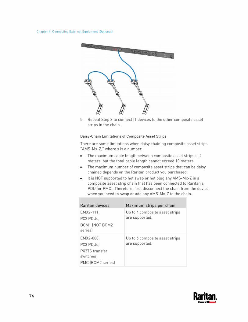
Chapter 4: Connecting External Equipment (Optional)
74
5. Repeat Step 3 to connect IT devices to the other composite asset
strips in the chain.
Daisy-Chain Limitations of Composite Asset Strips
There are some limitations when daisy chaining composite asset strips "AMS-Mx-Z," where x is a number.
The maximum cable length between composite asset strips is 2 meters, but the total cable length cannot exceed 10 meters.
The maximum number of composite asset strips that can be daisy chained depends on the Raritan product you purchased.
It is NOT supported to hot swap or hot plug any AMS-Mx-Z in a composite asset strip chain that has been connected to Raritan's PDU (or PMC). Therefore, first disconnect the chain from the device when you need to swap or add any AMS-Mx-Z to the chain.
Raritan devices Maximum strips per chain
EMX2-111, PX2 PDUs, BCM1 (NOT BCM2 series)
Up to 4 composite asset strips are supported.
EMX2-888, PX3 PDUs, PX3TS transfer switches PMC (BCM2 series)
Up to 6 composite asset strips are supported.
Chapter 4: Connecting External Equipment (Optional)
75
Note: In case you hot swap or hot plug any AMS-Mx-Z in a chain, causing the FEATURE port of the PX3 to malfunction, you can power cycle or reset the PX3 to restore the FEATURE port.
Connecting a Logitech Webcam
Connect webcams to PX3 in order to view videos or snapshots of the webcam's surrounding area.
The following USB Video Class (UVC) compliant webcam is supported:
Logitech® HD pro C920 Logitech® Webcam® Pro 9000, Model 960-000048
Other UVC-compliant webcams may also work. However, Raritan has neither tested them nor claimed that they will work properly.
Tip: You can easily find a list of UVC-compliant webcams on the Internet.
The PX3 supports up to two webcams. After connecting a webcam, you can retrieve visual information from anywhere through the PX3 web interface.
For more information on the Logitech webcam, refer to the user documentation accompanying it.
To connect a webcam: 1. Connect the webcam to the USB-A port on the PX3. The PX3
automatically detects the webcam. 2. Position the webcam properly.
Important: If a USB hub is used to connect the webcam, make sure it is a "powered" hub.
Snapshots or videos captured by the webcam are immediately displayed in the PX3 web interface after the connection is complete. See Configuring Webcams and Viewing Live Images (on page 433).
Connecting a GSM Modem
The following Cinterion® GSM modems can be connected to the PX3 in order to send SMS messages containing event information.
MC52iT MC55iT EHS6
See Available Actions (on page 336) for more information on SMS messages.
Chapter 4: Connecting External Equipment (Optional)
76
Note: PX3 cannot receive SMS messages.
To connect the GSM modem: 1. Connect the GSM modem to the serial port labeled CONSOLE /
MODEM on the PX3. A third party RJ-45 to "DB9 male" adapter/cable is required for
this connection. See RJ45-to-DB9 Cable Requirements for Modem Connections (on page 806).
2. Configure the GSM modem as needed. See the supporting GSM modem help for information on configuring the GSM modem.
3. Configure the GSM modem settings in the PX3 to specify the modem's SIM PIN number and the recipient phone number. See Configuring the Serial Port (on page 394).
Connecting an Analog Modem
The PX3 supports remote dial-in communications to access the CLI through an analog modem. This dial-in feature provides an additional alternative to access the PX3 when the LAN access is not available. To dial in to the PX3, the remote computer must have a modem connected and dial the correct phone number.
Below are the analog modems that the PX3 supports for sure:
NETCOMM IG6000 Industrial Grade SmartModem US Robotics 56K modem
The PX3 may also support other analog modems which Raritan did not test.
Note that the PX3 does NOT support dial-out or dial-back operations via the modem.
To connect an analog modem: 1. Plug a telephone cord into the phone jack of the supported modem. 2. Plug the modem's RS-232 cable into the serial port labeled
CONSOLE / MODEM on the PX3. A third party RJ-45 to "DB9 male" adapter/cable is required for
this connection. See RJ45-to-DB9 Cable Requirements for Modem Connections (on page 806).
You need to enable the modem dial-in support to take advantage of this feature, see Configuring the Serial Port (on page 394).
Chapter 4: Connecting External Equipment (Optional)
77
Connecting an External Beeper
The PX3 supports the use of an external beeper for audio alarms.
External beepers that are supported include but may not be limited to the following:
Mallory Sonalert MODEL SNP2R
After having an external beeper connected, you can create event rules for the PX3 to switch on or off the external beeper when specific events occur. See Event Rules and Actions (on page 314).
To connect an external beeper: 1. Connect a standard network patch cable to the FEATURE port of the
PX3. 2. Plug the other end of the cable into the external beeper's RJ-45
socket. The beeper can be located at a distance up to 330 feet (100 m) away from the PX3.
Connecting a Schroff LHX/SHX Heat Exchanger
To remotely monitor and administer the Schroff® LHX-20, LHX-40 and SHX-30 heat exchangers through the PX3 device, you must establish a connection between the heat exchanger and the PX3 device.
For more information on the LHX/SHX heat exchanger, see the user documentation accompanying that product.
To establish a connection between the PDU and LHX/SHX heat exchanger, an RJ-45 to RS-232 adapter cable provided by Schroff is required.
To connect an LHX or SHX heat exchanger: 1. Plug the RS-232 DB9 end of the adapter cable into the RS-232 port
on the Schroff LHX/SHX heat exchanger. 2. Plug the RJ-45 end of the cable into the port labeled FEATURE on
your PX3 device.
To enable the support of the LHX/SHX heat exchanger, see Miscellaneous (on page 402).
78
This chapter explains how to use the PX3 device, including:
Introduction to the LEDs and ports on the PDU Operation of the front panel display The overcurrent protector's behavior The internal beeper's behavior The reset button
In This Chapter
Panel Components ....................................................................................78 Circuit Breakers ......................................................................................125 Fuse..........................................................................................................127 Beeper......................................................................................................130 Replaceable Controller............................................................................130 Threaded Grounding Point ......................................................................132
Panel Components
PX3 comes in Zero U, 1U, and 2U sizes. All types of models come with the following components on the outer panels.
Inlet Outlets Connection ports Dot-matrix LCD display Reset button
Connection ports, the LCD display and reset button are located on a replaceable controller of the PX3 model. See Replaceable Controller (on page 130).
Inlet
Most of PX3 PDUs are shipped with a locking line cord, which is ready to be plugged into the PDU's inlet and an appropriate receptacle for electricity reception. Such devices cannot be rewired by the user.
A locking line cord helps secure the cord connection. For details, see Connecting a PX3 Locking Line Cord (on page 12).
Connect each PX3 to an appropriately rated branch circuit. See the label or nameplate affixed to your PX3 for appropriate input ratings or range of ratings.
Chapter 5 Introduction to PDU Components
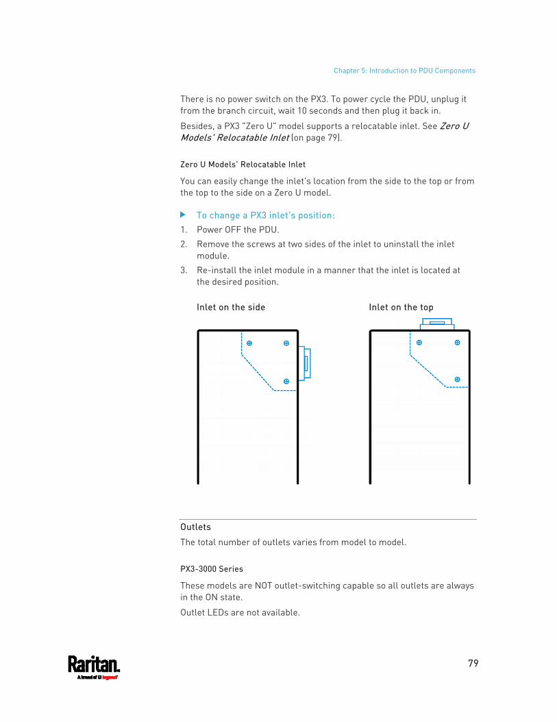
Chapter 5: Introduction to PDU Components
79
There is no power switch on the PX3. To power cycle the PDU, unplug it from the branch circuit, wait 10 seconds and then plug it back in.
Besides, a PX3 "Zero U" model supports a relocatable inlet. See Zero U Models' Relocatable Inlet (on page 79).
Zero U Models' Relocatable Inlet
You can easily change the inlet's location from the side to the top or from the top to the side on a Zero U model.
To change a PX3 inlet's position: 1. Power OFF the PDU. 2. Remove the screws at two sides of the inlet to uninstall the inlet
module. 3. Re-install the inlet module in a manner that the inlet is located at
the desired position.
Inlet on the side Inlet on the top
Outlets
The total number of outlets varies from model to model.
PX3-3000 Series
These models are NOT outlet-switching capable so all outlets are always in the ON state.
Outlet LEDs are not available.
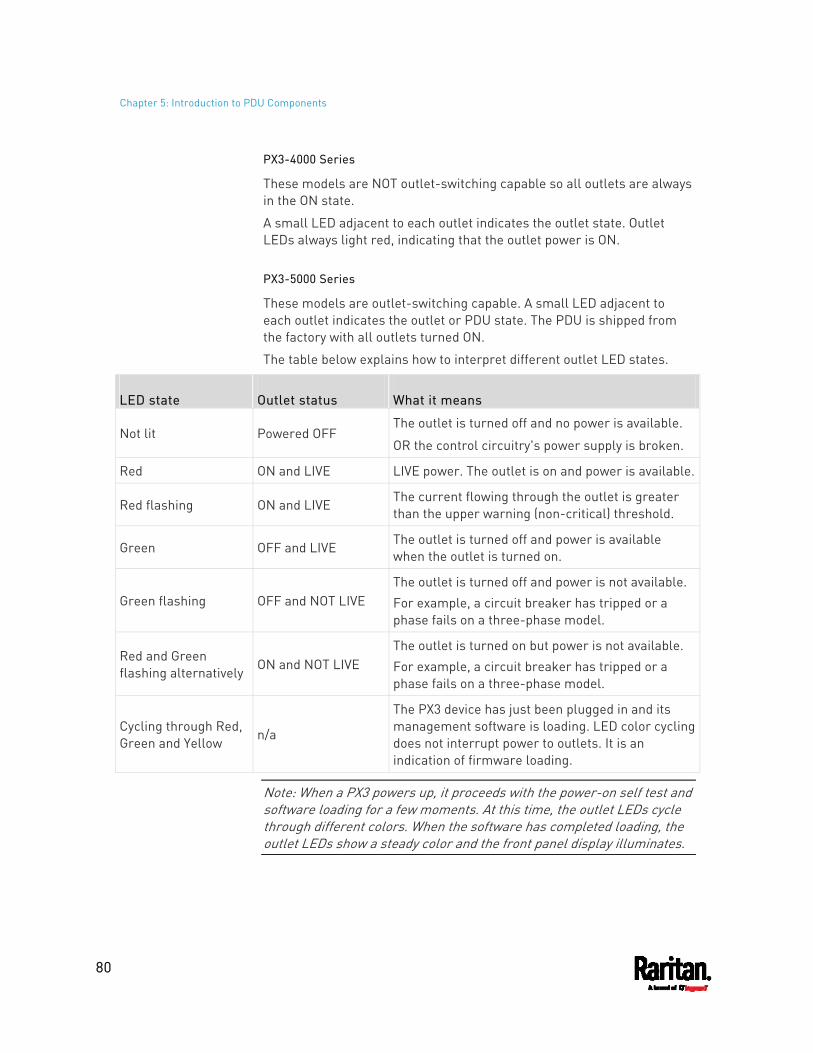
Chapter 5: Introduction to PDU Components
80
PX3-4000 Series
These models are NOT outlet-switching capable so all outlets are always in the ON state.
A small LED adjacent to each outlet indicates the outlet state. Outlet LEDs always light red, indicating that the outlet power is ON.
PX3-5000 Series
These models are outlet-switching capable. A small LED adjacent to each outlet indicates the outlet or PDU state. The PDU is shipped from the factory with all outlets turned ON.
The table below explains how to interpret different outlet LED states.
LED state Outlet status What it means
Not lit Powered OFF The outlet is turned off and no power is available.
OR the control circuitry's power supply is broken.
Red ON and LIVE LIVE power. The outlet is on and power is available.
Red flashing ON and LIVE The current flowing through the outlet is greater than the upper warning (non-critical) threshold.
Green OFF and LIVE The outlet is turned off and power is available when the outlet is turned on.
Green flashing OFF and NOT LIVE The outlet is turned off and power is not available. For example, a circuit breaker has tripped or a phase fails on a three-phase model.
Red and Green flashing alternatively ON and NOT LIVE
The outlet is turned on but power is not available. For example, a circuit breaker has tripped or a phase fails on a three-phase model.
Cycling through Red, Green and Yellow
n/a
The PX3 device has just been plugged in and its management software is loading. LED color cycling does not interrupt power to outlets. It is an indication of firmware loading.
Note: When a PX3 powers up, it proceeds with the power-on self test and software loading for a few moments. At this time, the outlet LEDs cycle through different colors. When the software has completed loading, the outlet LEDs show a steady color and the front panel display illuminates.
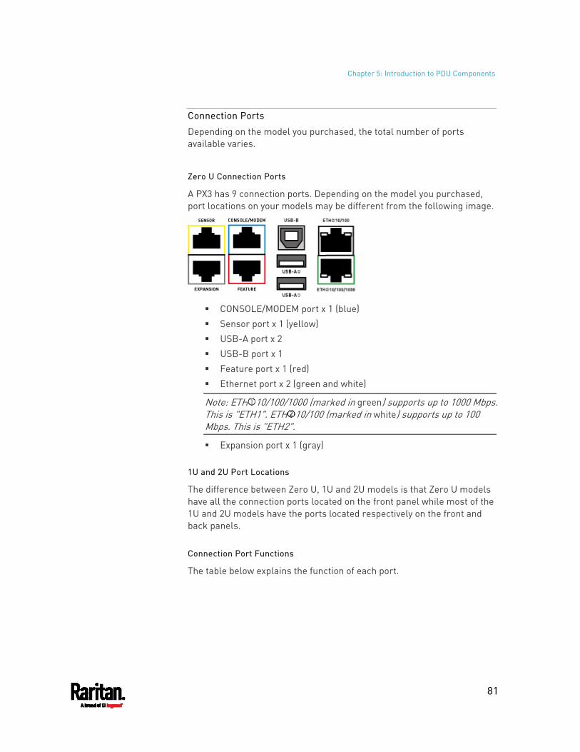
Chapter 5: Introduction to PDU Components
81
Connection Ports
Depending on the model you purchased, the total number of ports available varies.
Zero U Connection Ports
A PX3 has 9 connection ports. Depending on the model you purchased, port locations on your models may be different from the following image.
CONSOLE/MODEM port x 1 (blue) Sensor port x 1 (yellow) USB-A port x 2 USB-B port x 1 Feature port x 1 (red) Ethernet port x 2 (green and white)
Note: ETH 10/100/1000 (marked in green) supports up to 1000 Mbps. This is "ETH1". ETH 10/100 (marked in white) supports up to 100 Mbps. This is "ETH2".
Expansion port x 1 (gray)
1U and 2U Port Locations
The difference between Zero U, 1U and 2U models is that Zero U models have all the connection ports located on the front panel while most of the 1U and 2U models have the ports located respectively on the front and back panels.
Connection Port Functions
The table below explains the function of each port.
Chapter 5: Introduction to PDU Components
82
Port Used for...
USB-B Cascading PX3 devices for sharing a network connection. See Cascading All Devices via USB (on page 33).
Establishing a USB connection between a computer and the PX3 for: Using the command line interface. Performing the disaster recovery. Contact Raritan Technical
Support for instructions. Connecting to an Android mobile device for viewing or configuring
the PX3. See Connecting a Mobile Device to PX3 (on page 23).
USB-A This is a "host" port, which is powered, per USB 2.0 specifications.
Connecting to an iOS mobile device for viewing or configuring the PX3. See Connecting a Mobile Device to PX3 (on page 23).
Connecting a USB device, such as a Logitech® webcam or wireless LAN adapter.
Cascading PX3 devices for sharing a network connection.
FEATURE Connection to one of the following devices: A Raritan access product, such as Dominion KX III KVM switch,
with the use of a power CIM. A Schroff® LHX-20, SHX-30 or LHX-40 device, using an RJ-45 to
RS-232 cable provided by Schroff. An external beeper with the RJ-45 socket. A Raritan asset management strip, which allows you to track
the locations of IT devices on the rack. See Connecting External Equipment (Optional) (on page 46).
Warning: This is not an RS-232 port so do NOT plug in an RS-232 device, or damages can be caused to the device.
Chapter 5: Introduction to PDU Components
83
Port Used for...
CONSOLE/ MODEM (RJ-45)
Establishing a serial connection between the PX3 and a computer or modem.
You need a third-party RJ-45 to DB9 adapter/cable for the connection(s). Note that the RJ-45 to DB9 adapter/cable for connecting a computer is different from the one for connecting a modem. For details, refer to:
RJ45-to-DB9 Cable Requirements for Computer Connections (on page 30)
RJ45-to-DB9 Cable Requirements for Modem Connections (on page 806)
SENSOR (RJ-45)
Connection to one of the following devices: Raritan's environmental sensor package(s). Raritan's sensor hub, which expands the number of a sensor
port to four ports.
ETH 10/100/1000, ETH 10/100
PX3 has two Ethernet ports. ETH 10/100/1000 (marked in green) supports up to 1000 Mbps.
This is "ETH1". ETH 10/100 (marked in white) supports up to 100 Mbps. This is
"ETH2". Connecting the PX3 to your company's network via a standard network patch cable (Cat5e/6). This connection is necessary to administer or access the PX3 remotely. There are two small LEDs adjacent to the port:
Green indicates a physical link and activity. Yellow indicates communications at 10/100 BaseT speeds. Note that the yellow LED of the ETH 10/100 port has NO
function so it will not be lit regardless of the communication status.
You can use either Ethernet port for network connection or cascading. See Extended Cascading with PX3 Devices (on page 36).
Note: Network connection to this port is not required if wireless connection is preferred, or if the PX3 is a slave device in the cascading configuration.
EXPANSION Connecting to the EXPANSION port of another PX3 so that the power supply to either PX3 controller will continue whenever power failure occurs on the inlet of one PX3 PDU. See Power-Sharing Restrictions and Connection (on page 41).
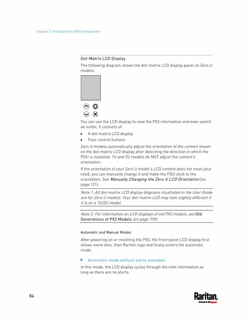
Chapter 5: Introduction to PDU Components
84
Dot-Matrix LCD Display
The following diagram shows the dot-matrix LCD display panel on Zero U models.
You can use the LCD display to view the PX3 information and even switch an outlet. It consists of:
A dot-matrix LCD display Four control buttons
Zero U models automatically adjust the orientation of the content shown on the dot-matrix LCD display after detecting the direction in which the PDU is installed. 1U and 2U models do NOT adjust the content's orientation.
If the orientation of your Zero U model's LCD content does not meet your need, you can manually change it and make the PDU stick to the orientation. See Manually Changing the Zero U LCD Orientation (on page 121).
Note 1: All dot-matrix LCD display diagrams illustrated in the User Guide are for Zero U models. Your dot-matrix LCD may look slightly different if it is on a 1U/2U model.
Note 2: For information on LCD displays of old PX3 models, see Old Generations of PX3 Models (on page 739).
Automatic and Manual Modes
After powering on or resetting the PX3, the front panel LCD display first shows some dots, then Raritan logo and finally enters the automatic mode.
Automatic mode without alerts available:
In this mode, the LCD display cycles through the inlet information as long as there are no alerts.
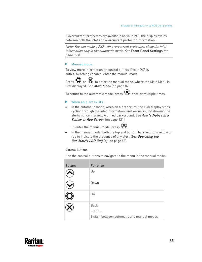
Chapter 5: Introduction to PDU Components
85
If overcurrent protectors are available on your PX3, the display cycles between both the inlet and overcurrent protector information.
Note: You can make a PX3 with overcurrent protectors show the inlet information only in the automatic mode. See Front Panel Settings (on page 393).
Manual mode:
To view more information or control outlets if your PX3 is outlet-switching capable, enter the manual mode.
Press or to enter the manual mode, where the Main Menu is first displayed. See Main Menu (on page 87).
To return to the automatic mode, press once or multiple times.
When an alert exists: In the automatic mode, when an alert occurs, the LCD display stops
cycling through the inlet information, and warns you by showing the alerts notice in a yellow or red background. See Alerts Notice in a Yellow or Red Screen (on page 121).
To enter the manual mode, press . In the manual mode, both the top and bottom bars will turn yellow or
red to indicate the presence of any alert. See Operating the Dot-Matrix LCD Display (on page 86).
Control Buttons
Use the control buttons to navigate to the menu in the manual mode.
Button Function
Up
Down
OK
Back
-- OR --
Switch between automatic and manual modes
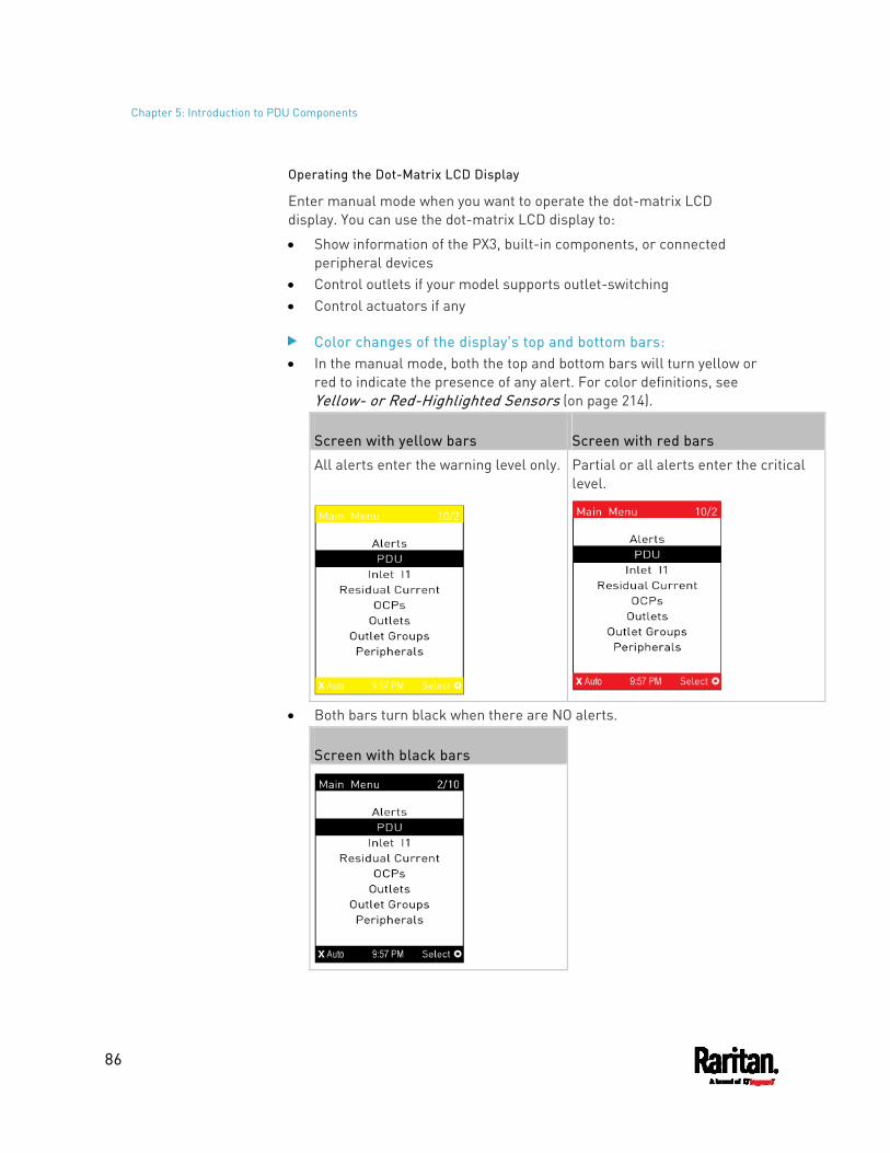
Chapter 5: Introduction to PDU Components
86
Operating the Dot-Matrix LCD Display
Enter manual mode when you want to operate the dot-matrix LCD display. You can use the dot-matrix LCD display to:
Show information of the PX3, built-in components, or connected peripheral devices
Control outlets if your model supports outlet-switching Control actuators if any
Color changes of the display's top and bottom bars: In the manual mode, both the top and bottom bars will turn yellow or
red to indicate the presence of any alert. For color definitions, see Yellow- or Red-Highlighted Sensors (on page 214).
Screen with yellow bars Screen with red bars
All alerts enter the warning level only.
Partial or all alerts enter the critical level.
Both bars turn black when there are NO alerts.
Screen with black bars
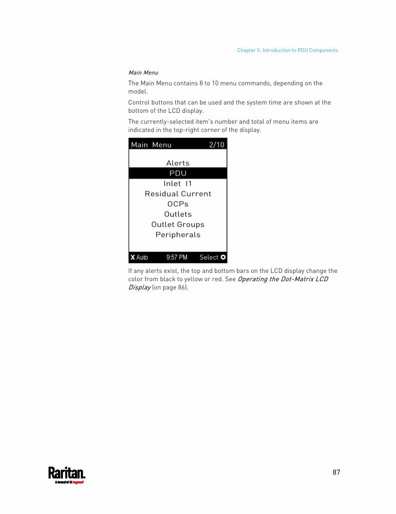
Chapter 5: Introduction to PDU Components
87
Main Menu
The Main Menu contains 8 to 10 menu commands, depending on the model.
Control buttons that can be used and the system time are shown at the bottom of the LCD display.
The currently-selected item's number and total of menu items are indicated in the top-right corner of the display.
If any alerts exist, the top and bottom bars on the LCD display change the color from black to yellow or red. See Operating the Dot-Matrix LCD Display (on page 86).
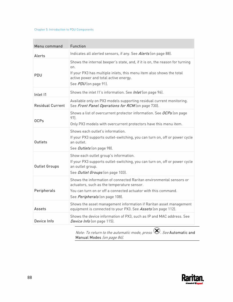
Chapter 5: Introduction to PDU Components
88
Menu command Function
Alerts Indicates all alerted sensors, if any. See Alerts (on page 88).
PDU
Shows the internal beeper's state, and, if it is on, the reason for turning on. If your PX3 has multiple inlets, this menu item also shows the total active power and total active energy. See PDU (on page 91).
Inlet I1 Shows the inlet I1's information. See Inlet (on page 96).
Residual Current Available only on PX3 models supporting residual current monitoring. See Front Panel Operations for RCM (on page 730).
OCPs
Shows a list of overcurrent protector information. See OCPs (on page 97). Only PX3 models with overcurrent protectors have this menu item.
Outlets
Shows each outlet's information. If your PX3 supports outlet-switching, you can turn on, off or power cycle an outlet. See Outlets (on page 98).
Outlet Groups
Show each outlet group's information. If your PX3 supports outlet-switching, you can turn on, off or power cycle an outlet group. See Outlet Groups (on page 103).
Peripherals
Shows the information of connected Raritan environmental sensors or actuators, such as the temperature sensor. You can turn on or off a connected actuator with this command. See Peripherals (on page 108).
Assets Shows the asset management information if Raritan asset management equipment is connected to your PX3. See Assets (on page 112).
Device Info Shows the device information of PX3, such as IP and MAC address. See Device Info (on page 115).
Note: To return to the automatic mode, press . See Automatic and Manual Modes (on page 84).
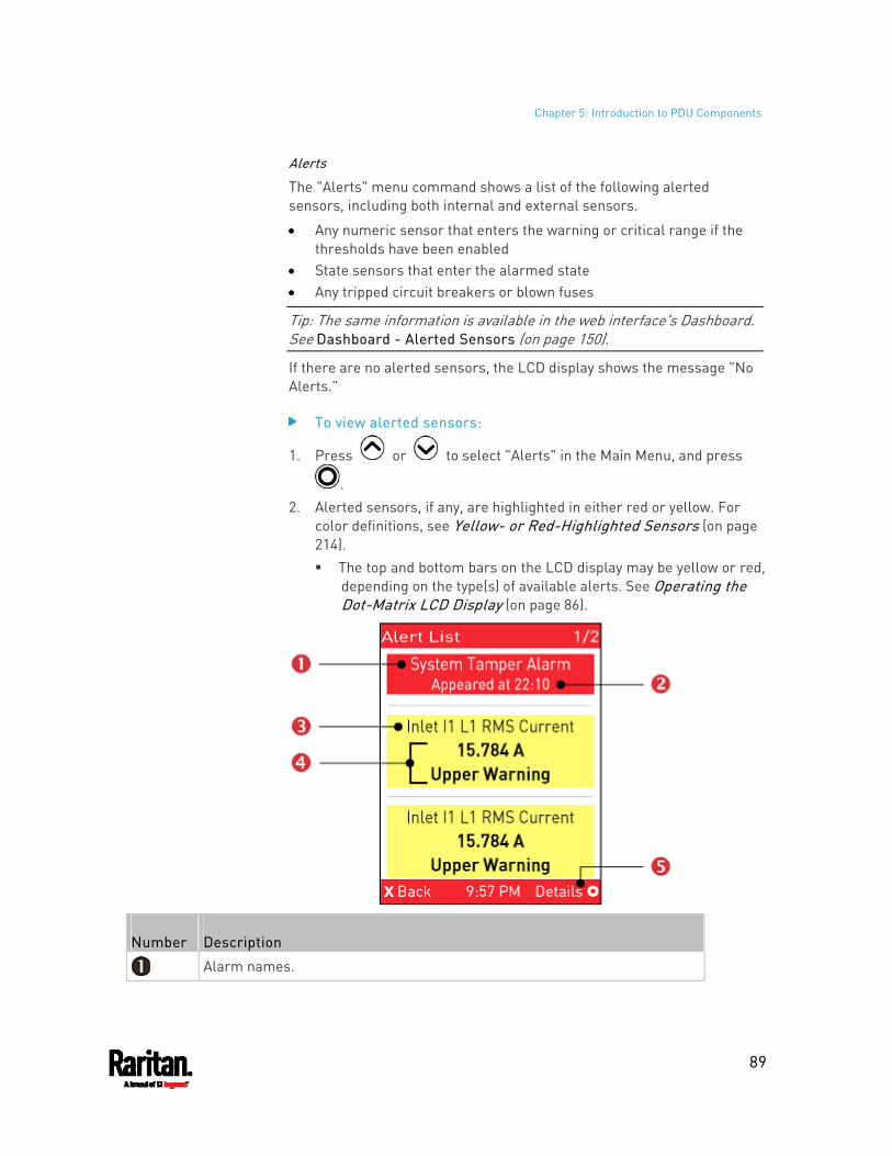
Chapter 5: Introduction to PDU Components
89
Alerts
The "Alerts" menu command shows a list of the following alerted sensors, including both internal and external sensors.
Any numeric sensor that enters the warning or critical range if the thresholds have been enabled
State sensors that enter the alarmed state Any tripped circuit breakers or blown fuses
Tip: The same information is available in the web interface's Dashboard. See Dashboard - Alerted Sensors (on page 150).
If there are no alerted sensors, the LCD display shows the message "No Alerts."
To view alerted sensors:
1. Press or to select "Alerts" in the Main Menu, and press
. 2. Alerted sensors, if any, are highlighted in either red or yellow. For
color definitions, see Yellow- or Red-Highlighted Sensors (on page 214). The top and bottom bars on the LCD display may be yellow or red,
depending on the type(s) of available alerts. See Operating the Dot-Matrix LCD Display (on page 86).
Number Description
Alarm names.
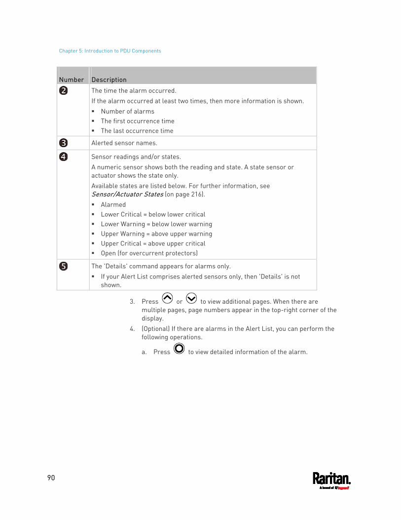
Chapter 5: Introduction to PDU Components
90
Number Description
The time the alarm occurred. If the alarm occurred at least two times, then more information is shown. Number of alarms The first occurrence time The last occurrence time
Alerted sensor names.
Sensor readings and/or states. A numeric sensor shows both the reading and state. A state sensor or actuator shows the state only. Available states are listed below. For further information, see Sensor/Actuator States (on page 216). Alarmed Lower Critical = below lower critical Lower Warning = below lower warning Upper Warning = above upper warning Upper Critical = above upper critical Open (for overcurrent protectors)
The 'Details' command appears for alarms only. If your Alert List comprises alerted sensors only, then 'Details' is not
shown.
3. Press or to view additional pages. When there are multiple pages, page numbers appear in the top-right corner of the display.
4. (Optional) If there are alarms in the Alert List, you can perform the following operations.
a. Press to view detailed information of the alarm.
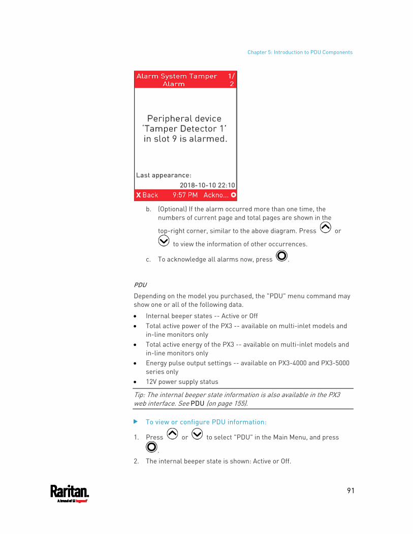
Chapter 5: Introduction to PDU Components
91
b. (Optional) If the alarm occurred more than one time, the
numbers of current page and total pages are shown in the
top-right corner, similar to the above diagram. Press or
to view the information of other occurrences.
c. To acknowledge all alarms now, press .
PDU
Depending on the model you purchased, the "PDU" menu command may show one or all of the following data.
Internal beeper states -- Active or Off Total active power of the PX3 -- available on multi-inlet models and
in-line monitors only Total active energy of the PX3 -- available on multi-inlet models and
in-line monitors only Energy pulse output settings -- available on PX3-4000 and PX3-5000
series only 12V power supply status
Tip: The internal beeper state information is also available in the PX3 web interface. See PDU (on page 155).
To view or configure PDU information:
1. Press or to select "PDU" in the Main Menu, and press
. 2. The internal beeper state is shown: Active or Off.
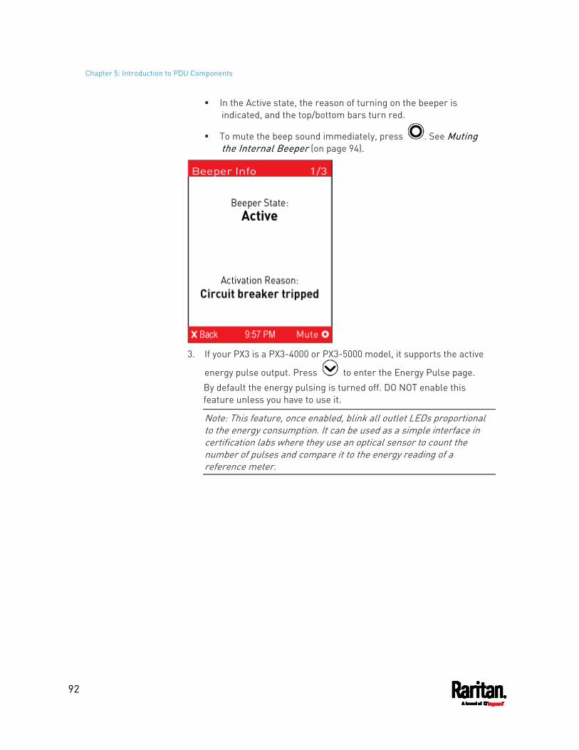
Chapter 5: Introduction to PDU Components
92
In the Active state, the reason of turning on the beeper is indicated, and the top/bottom bars turn red.
To mute the beep sound immediately, press . See Muting the Internal Beeper (on page 94).
3. If your PX3 is a PX3-4000 or PX3-5000 model, it supports the active
energy pulse output. Press to enter the Energy Pulse page. By default the energy pulsing is turned off. DO NOT enable this feature unless you have to use it.
Note: This feature, once enabled, blink all outlet LEDs proportional to the energy consumption. It can be used as a simple interface in certification labs where they use an optical sensor to count the number of pulses and compare it to the energy reading of a reference meter.
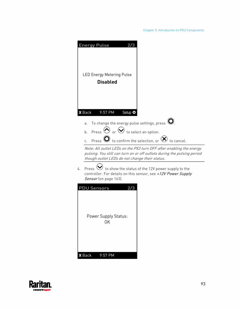
Chapter 5: Introduction to PDU Components
93
a. To change the energy pulse settings, press .
b. Press or to select an option.
c. Press to confirm the selection, or to cancel.
Note: All outlet LEDs on the PX3 turn OFF after enabling the energy pulsing. You still can turn on or off outlets during the pulsing period though outlet LEDs do not change their status.
4. Press to show the status of the 12V power supply to the controller. For details on this sensor, see +12V Power Supply Sensor (on page 163).
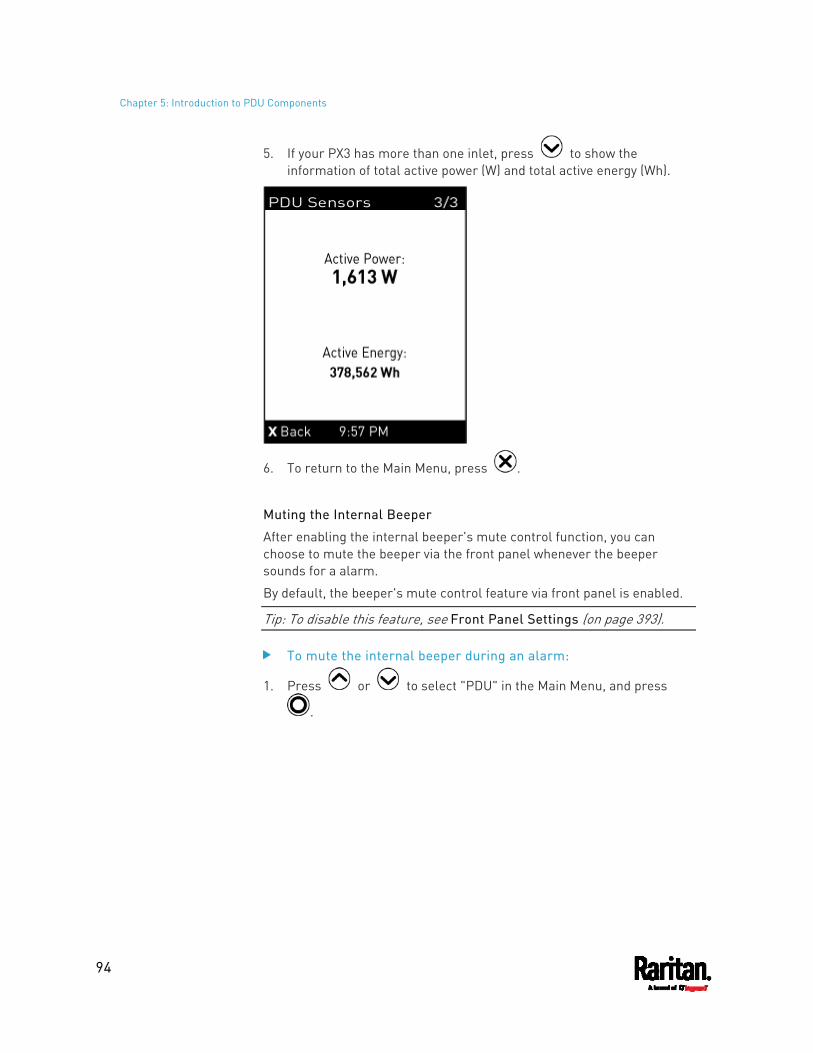
Chapter 5: Introduction to PDU Components
94
5. If your PX3 has more than one inlet, press to show the information of total active power (W) and total active energy (Wh).
6. To return to the Main Menu, press .
Muting the Internal Beeper
After enabling the internal beeper's mute control function, you can choose to mute the beeper via the front panel whenever the beeper sounds for a alarm.
By default, the beeper's mute control feature via front panel is enabled.
Tip: To disable this feature, see Front Panel Settings (on page 393).
To mute the internal beeper during an alarm:
1. Press or to select "PDU" in the Main Menu, and press
.
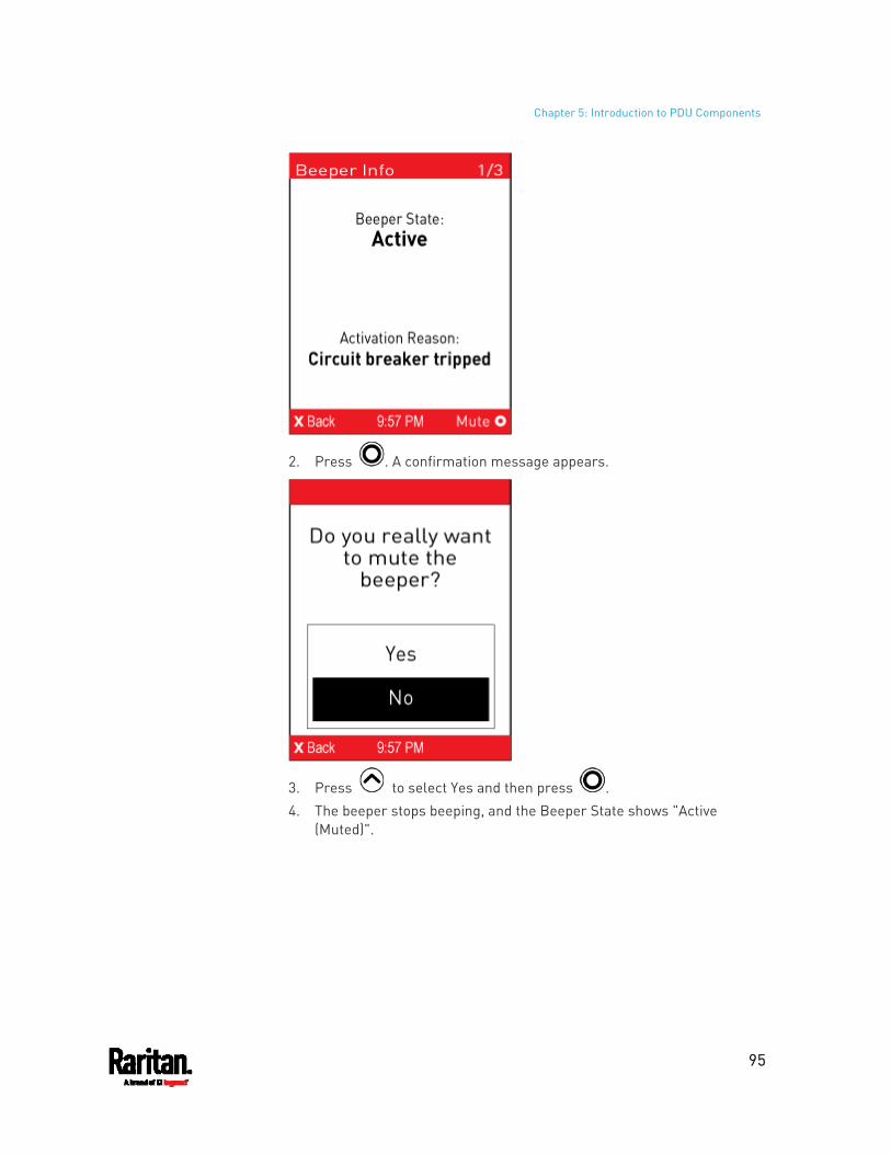
Chapter 5: Introduction to PDU Components
95
2. Press . A confirmation message appears.
3. Press to select Yes and then press . 4. The beeper stops beeping, and the Beeper State shows "Active
(Muted)".
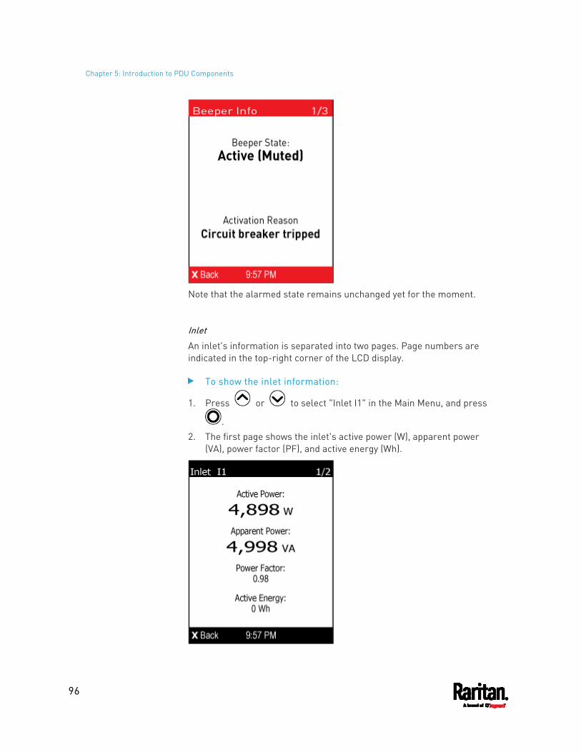
Chapter 5: Introduction to PDU Components
96
Note that the alarmed state remains unchanged yet for the moment.
Inlet
An inlet's information is separated into two pages. Page numbers are indicated in the top-right corner of the LCD display.
To show the inlet information:
1. Press or to select "Inlet I1" in the Main Menu, and press
. 2. The first page shows the inlet's active power (W), apparent power
(VA), power factor (PF), and active energy (Wh).
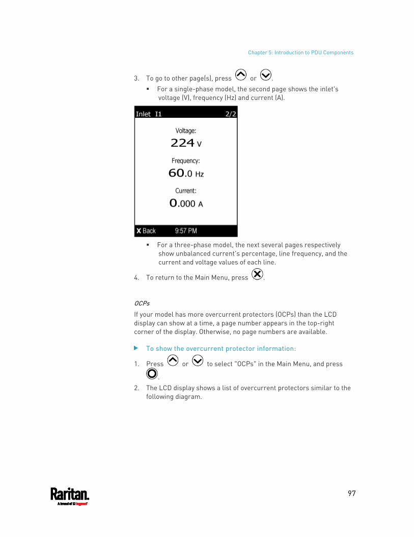
Chapter 5: Introduction to PDU Components
97
3. To go to other page(s), press or . For a single-phase model, the second page shows the inlet's
voltage (V), frequency (Hz) and current (A).
For a three-phase model, the next several pages respectively
show unbalanced current's percentage, line frequency, and the current and voltage values of each line.
4. To return to the Main Menu, press .
OCPs
If your model has more overcurrent protectors (OCPs) than the LCD display can show at a time, a page number appears in the top-right corner of the display. Otherwise, no page numbers are available.
To show the overcurrent protector information:
1. Press or to select "OCPs" in the Main Menu, and press
. 2. The LCD display shows a list of overcurrent protectors similar to the
following diagram.
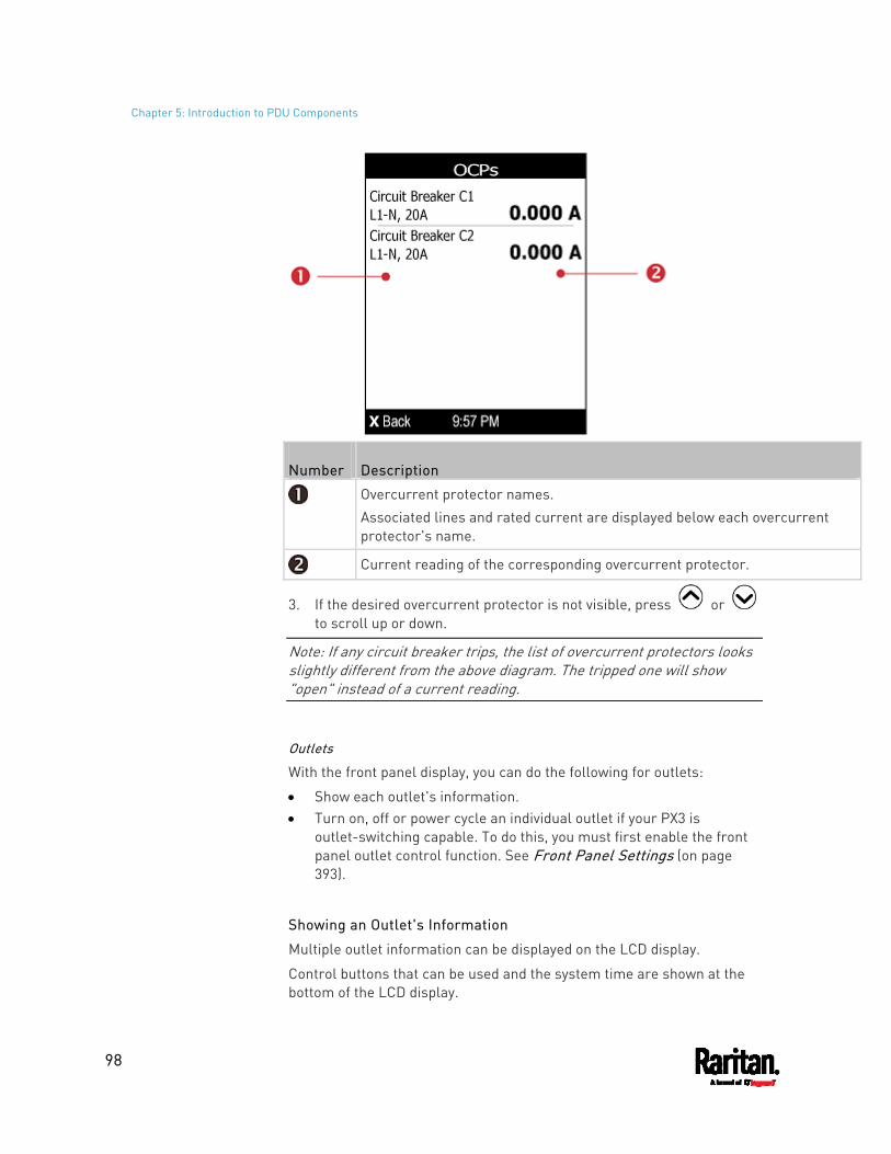
Chapter 5: Introduction to PDU Components
98
Number Description
Overcurrent protector names. Associated lines and rated current are displayed below each overcurrent protector's name.
Current reading of the corresponding overcurrent protector.
3. If the desired overcurrent protector is not visible, press or to scroll up or down.
Note: If any circuit breaker trips, the list of overcurrent protectors looks slightly different from the above diagram. The tripped one will show "open" instead of a current reading.
Outlets
With the front panel display, you can do the following for outlets:
Show each outlet's information. Turn on, off or power cycle an individual outlet if your PX3 is
outlet-switching capable. To do this, you must first enable the front panel outlet control function. See Front Panel Settings (on page 393).
Showing an Outlet's Information
Multiple outlet information can be displayed on the LCD display.
Control buttons that can be used and the system time are shown at the bottom of the LCD display.
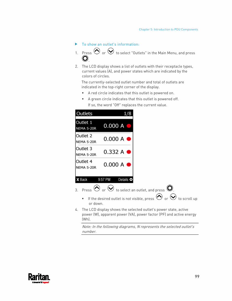
Chapter 5: Introduction to PDU Components
99
To show an outlet's information:
1. Press or to select "Outlets" in the Main Menu, and press
. 2. The LCD display shows a list of outlets with their receptacle types,
current values (A), and power states which are indicated by the colors of circles. The currently-selected outlet number and total of outlets are indicated in the top-right corner of the display. A red circle indicates that this outlet is powered on. A green circle indicates that this outlet is powered off.
If so, the word "Off" replaces the current value.
3. Press or to select an outlet, and press .
If the desired outlet is not visible, press or to scroll up or down.
4. The LCD display shows the selected outlet's power state, active power (W), apparent power (VA), power factor (PF) and active energy (Wh).
Note: In the following diagrams, N represents the selected outlet's number.
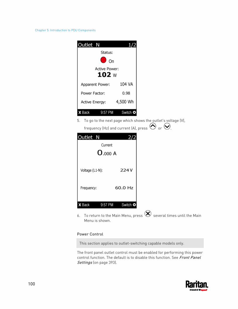
Chapter 5: Introduction to PDU Components
100
5. To go to the next page which shows the outlet's voltage (V),
frequency (Hz) and current (A), press or .
6. To return to the Main Menu, press several times until the Main Menu is shown.
Power Control
This section applies to outlet-switching capable models only.
The front panel outlet control must be enabled for performing this power control function. The default is to disable this function. See Front Panel Settings (on page 393).
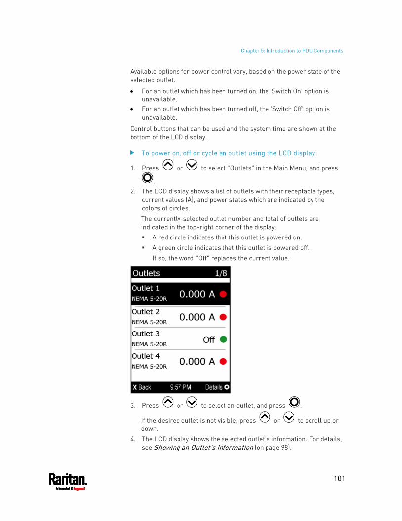
Chapter 5: Introduction to PDU Components
101
Available options for power control vary, based on the power state of the selected outlet.
For an outlet which has been turned on, the 'Switch On' option is unavailable.
For an outlet which has been turned off, the 'Switch Off' option is unavailable.
Control buttons that can be used and the system time are shown at the bottom of the LCD display.
To power on, off or cycle an outlet using the LCD display:
1. Press or to select "Outlets" in the Main Menu, and press
. 2. The LCD display shows a list of outlets with their receptacle types,
current values (A), and power states which are indicated by the colors of circles. The currently-selected outlet number and total of outlets are indicated in the top-right corner of the display. A red circle indicates that this outlet is powered on. A green circle indicates that this outlet is powered off.
If so, the word "Off" replaces the current value.
3. Press or to select an outlet, and press .
If the desired outlet is not visible, press or to scroll up or down.
4. The LCD display shows the selected outlet's information. For details, see Showing an Outlet's Information (on page 98).
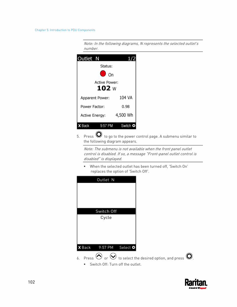
Chapter 5: Introduction to PDU Components
102
Note: In the following diagrams, N represents the selected outlet's number.
5. Press to go to the power control page. A submenu similar to the following diagram appears.
Note: The submenu is not available when the front panel outlet control is disabled. If so, a message "Front-panel outlet control is disabled" is displayed.
When the selected outlet has been turned off, 'Switch On' replaces the option of 'Switch Off'.
6. Press or to select the desired option, and press . Switch Off: Turn off the outlet.
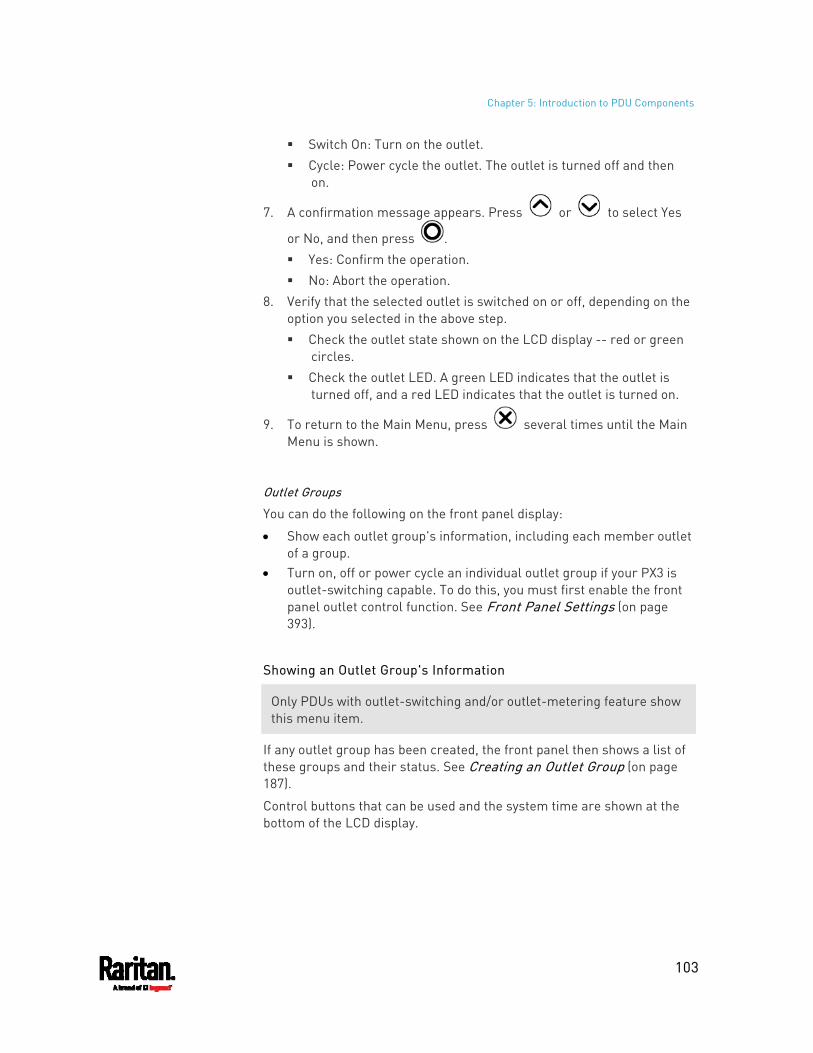
Chapter 5: Introduction to PDU Components
103
Switch On: Turn on the outlet. Cycle: Power cycle the outlet. The outlet is turned off and then
on.
7. A confirmation message appears. Press or to select Yes
or No, and then press . Yes: Confirm the operation. No: Abort the operation.
8. Verify that the selected outlet is switched on or off, depending on the option you selected in the above step. Check the outlet state shown on the LCD display -- red or green
circles. Check the outlet LED. A green LED indicates that the outlet is
turned off, and a red LED indicates that the outlet is turned on.
9. To return to the Main Menu, press several times until the Main Menu is shown.
Outlet Groups
You can do the following on the front panel display:
Show each outlet group's information, including each member outlet of a group.
Turn on, off or power cycle an individual outlet group if your PX3 is outlet-switching capable. To do this, you must first enable the front panel outlet control function. See Front Panel Settings (on page 393).
Showing an Outlet Group's Information
Only PDUs with outlet-switching and/or outlet-metering feature show this menu item.
If any outlet group has been created, the front panel then shows a list of these groups and their status. See Creating an Outlet Group (on page 187).
Control buttons that can be used and the system time are shown at the bottom of the LCD display.
Chapter 5: Introduction to PDU Components
104
To show an outlet group's information:
1. Press or to select "Outlet Groups" in the Main Menu, and
press . 2. The LCD display shows a list of outlet groups with the information
below: The total number of outlets in the group Power states which are indicated by the colors of circles Each group's active power value
The currently-selected outlet group's number and total of outlet groups are indicated in the top-right corner of the display, such as "1/4" in the above diagram. A red circle indicates that all outlets of the group are powered
on. A green circle indicates that all outlets of the group are powered
off. A half-red half-green circle indicates some outlets are powered
on while the others of the group are powered off.
3. Press or to select an outlet group, and press .
If the desired outlet group is not visible, press or to scroll up or down.
4. The LCD display shows the selected outlet group's power state, active power (W), and active energy (Wh).
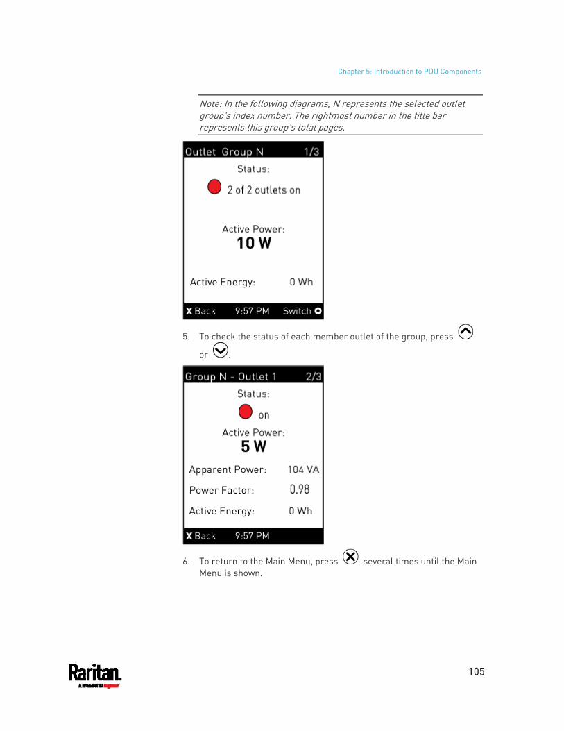
Chapter 5: Introduction to PDU Components
105
Note: In the following diagrams, N represents the selected outlet group's index number. The rightmost number in the title bar represents this group's total pages.
5. To check the status of each member outlet of the group, press
or .
6. To return to the Main Menu, press several times until the Main Menu is shown.
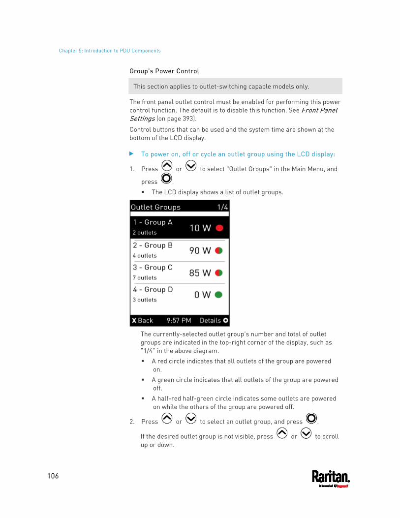
Chapter 5: Introduction to PDU Components
106
Group's Power Control
This section applies to outlet-switching capable models only.
The front panel outlet control must be enabled for performing this power control function. The default is to disable this function. See Front Panel Settings (on page 393).
Control buttons that can be used and the system time are shown at the bottom of the LCD display.
To power on, off or cycle an outlet group using the LCD display:
1. Press or to select "Outlet Groups" in the Main Menu, and
press . The LCD display shows a list of outlet groups.
The currently-selected outlet group's number and total of outlet groups are indicated in the top-right corner of the display, such as "1/4" in the above diagram. A red circle indicates that all outlets of the group are powered
on. A green circle indicates that all outlets of the group are powered
off. A half-red half-green circle indicates some outlets are powered
on while the others of the group are powered off.
2. Press or to select an outlet group, and press .
If the desired outlet group is not visible, press or to scroll up or down.
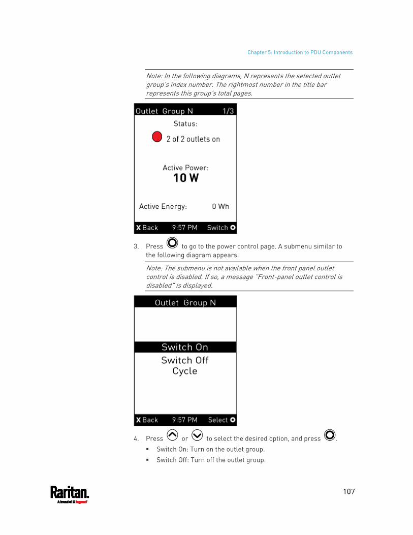
Chapter 5: Introduction to PDU Components
107
Note: In the following diagrams, N represents the selected outlet group's index number. The rightmost number in the title bar represents this group's total pages.
3. Press to go to the power control page. A submenu similar to the following diagram appears.
Note: The submenu is not available when the front panel outlet control is disabled. If so, a message "Front-panel outlet control is disabled" is displayed.
4. Press or to select the desired option, and press . Switch On: Turn on the outlet group. Switch Off: Turn off the outlet group.
Chapter 5: Introduction to PDU Components
108
Cycle: Power cycle the outlet group.
5. A confirmation message appears. Press or to select Yes
or No, and then press . Yes: Confirm the operation. No: Abort the operation.
6. Verify that the selected outlet group is switched on or off, depending on the option you selected in the above step. Check the outlet group state shown on the LCD display -- red or
green circles. Check each member outlet's LED of the group. A green LED
indicates that the outlet is turned off, and a red LED indicates that the outlet is turned on.
7. To return to the Main Menu, press several times until the Main Menu is shown.
Peripherals
If there are no Raritan environmental sensor packages connected to your PX3, the LCD display shows the message "No managed devices" for the "Peripherals" menu command.
If you have enabled the front panel actuator control function, you can switch on or off a connected actuator using the LCD display. See Miscellaneous (on page 402).
To show environmental sensor or actuator information:
1. Press or to select "Peripherals" in the Main Menu, and
press . 2. The display shows a list of environmental sensors/actuators.
If the desired sensor or actuator is not visible, press or to scroll up or down.
When the list exceeds one page, the currently-selected sensor/actuator's ID number and total of managed sensors/actuators are indicated in the top-right corner of the display.
If any sensor enters the warning, critical, or alarmed state, like 'Tamper Detector 1' shown below, it is highlighted in yellow or red. For color definitions, see Yellow- or Red-Highlighted Sensors (on page 214).
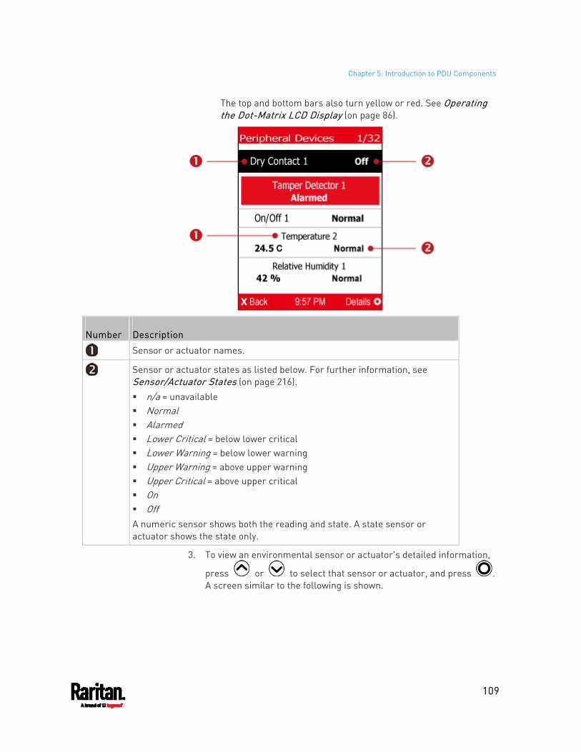
Chapter 5: Introduction to PDU Components
109
The top and bottom bars also turn yellow or red. See Operating the Dot-Matrix LCD Display (on page 86).
Number Description
Sensor or actuator names.
Sensor or actuator states as listed below. For further information, see Sensor/Actuator States (on page 216). n/a = unavailable Normal Alarmed Lower Critical = below lower critical Lower Warning = below lower warning Upper Warning = above upper warning Upper Critical = above upper critical On Off A numeric sensor shows both the reading and state. A state sensor or actuator shows the state only.
3. To view an environmental sensor or actuator's detailed information,
press or to select that sensor or actuator, and press . A screen similar to the following is shown.
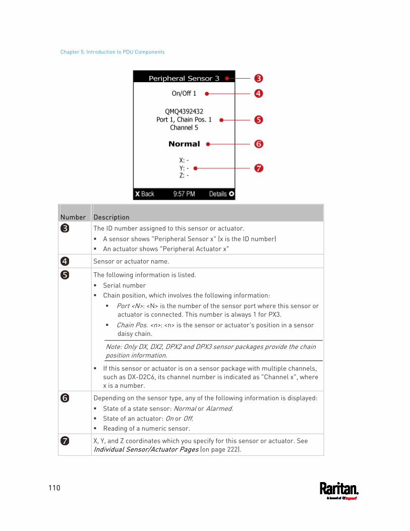
Chapter 5: Introduction to PDU Components
110
Number Description
The ID number assigned to this sensor or actuator. A sensor shows "Peripheral Sensor x" (x is the ID number) An actuator shows "Peripheral Actuator x"
Sensor or actuator name.
The following information is listed. Serial number Chain position, which involves the following information:
Port <N>: <N> is the number of the sensor port where this sensor or actuator is connected. This number is always 1 for PX3.
Chain Pos. <n>: <n> is the sensor or actuator's position in a sensor daisy chain.
Note: Only DX, DX2, DPX2 and DPX3 sensor packages provide the chain position information.
If this sensor or actuator is on a sensor package with multiple channels, such as DX-D2C6, its channel number is indicated as "Channel x", where x is a number.
Depending on the sensor type, any of the following information is displayed: State of a state sensor: Normal or Alarmed. State of an actuator: On or Off. Reading of a numeric sensor.
X, Y, and Z coordinates which you specify for this sensor or actuator. See Individual Sensor/Actuator Pages (on page 222).
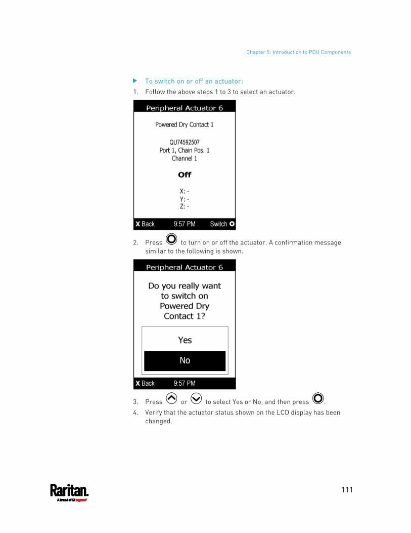
Chapter 5: Introduction to PDU Components
111
To switch on or off an actuator: 1. Follow the above steps 1 to 3 to select an actuator.
2. Press to turn on or off the actuator. A confirmation message similar to the following is shown.
3. Press or to select Yes or No, and then press . 4. Verify that the actuator status shown on the LCD display has been
changed.
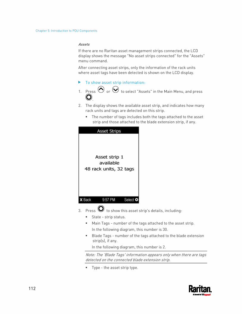
Chapter 5: Introduction to PDU Components
112
Assets
If there are no Raritan asset management strips connected, the LCD display shows the message "No asset strips connected" for the "Assets" menu command.
After connecting asset strips, only the information of the rack units where asset tags have been detected is shown on the LCD display.
To show asset strip information:
1. Press or to select "Assets" in the Main Menu, and press
. 2. The display shows the available asset strip, and indicates how many
rack units and tags are detected on this strip. The number of tags includes both the tags attached to the asset
strip and those attached to the blade extension strip, if any.
3. Press to show this asset strip's details, including: State - strip status. Main Tags - number of the tags attached to the asset strip.
In the following diagram, this number is 30. Blade Tags - number of the tags attached to the blade extension
strip(s), if any. In the following diagram, this number is 2.
Note: The 'Blade Tags' information appears only when there are tags detected on the connected blade extension strip.
Type - the asset strip type.
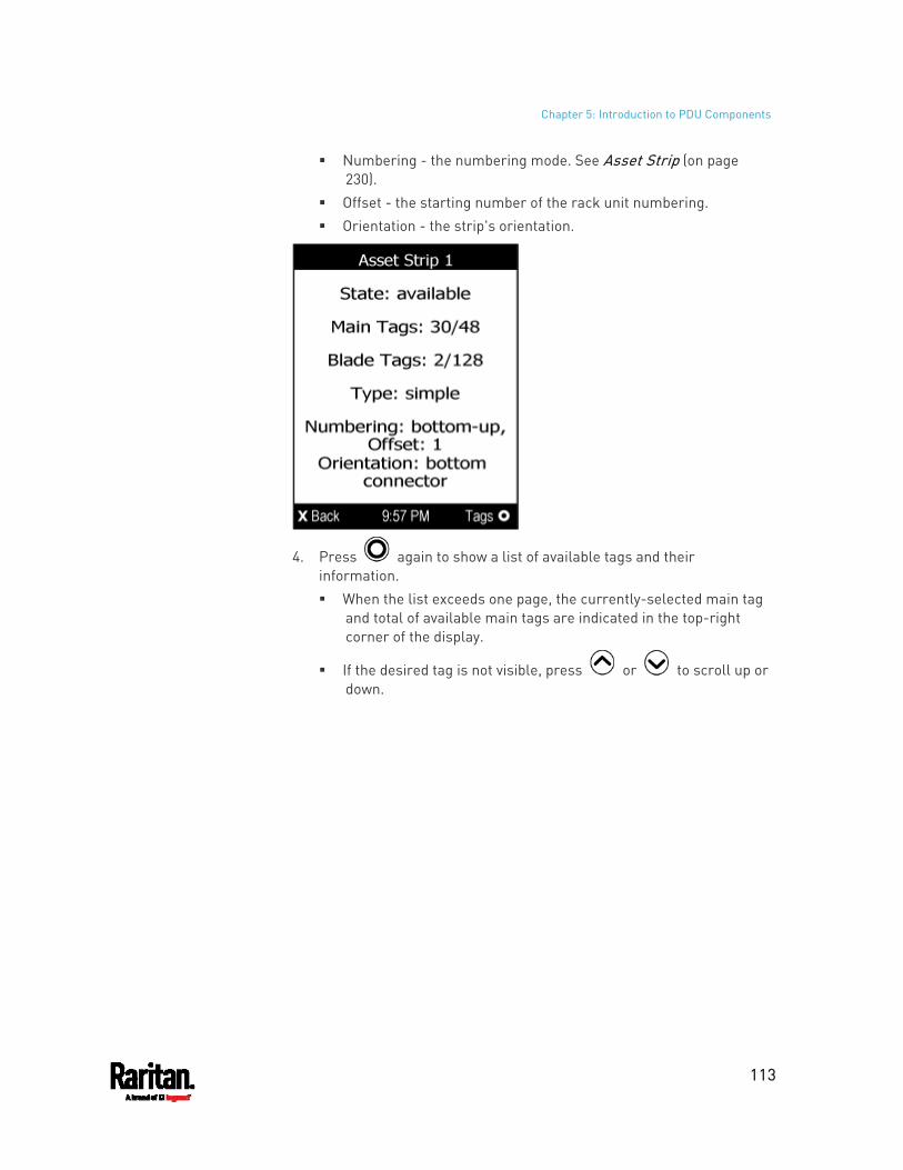
Chapter 5: Introduction to PDU Components
113
Numbering - the numbering mode. See Asset Strip (on page 230).
Offset - the starting number of the rack unit numbering. Orientation - the strip's orientation.
4. Press again to show a list of available tags and their information. When the list exceeds one page, the currently-selected main tag
and total of available main tags are indicated in the top-right corner of the display.
If the desired tag is not visible, press or to scroll up or down.
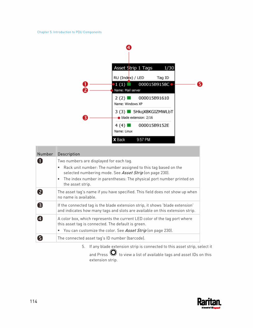
Chapter 5: Introduction to PDU Components
114
Number Description
Two numbers are displayed for each tag. Rack unit number: The number assigned to this tag based on the
selected numbering mode. See Asset Strip (on page 230). The index number in parentheses: The physical port number printed on
the asset strip.
The asset tag's name if you have specified. This field does not show up when no name is available.
If the connected tag is the blade extension strip, it shows 'blade extension' and indicates how many tags and slots are available on this extension strip.
A color box, which represents the current LED color of the tag port where this asset tag is connected. The default is green. You can customize the color. See Asset Strip (on page 230).
The connected asset tag's ID number (barcode).
5. If any blade extension strip is connected to this asset strip, select it
and Press to view a list of available tags and asset IDs on this extension strip.
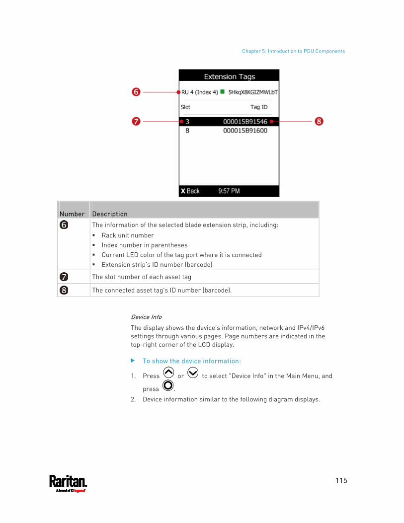
Chapter 5: Introduction to PDU Components
115
Number Description
The information of the selected blade extension strip, including: Rack unit number Index number in parentheses Current LED color of the tag port where it is connected Extension strip's ID number (barcode)
The slot number of each asset tag
The connected asset tag's ID number (barcode).
Device Info
The display shows the device's information, network and IPv4/IPv6 settings through various pages. Page numbers are indicated in the top-right corner of the LCD display.
To show the device information:
1. Press or to select "Device Info" in the Main Menu, and
press . 2. Device information similar to the following diagram displays.
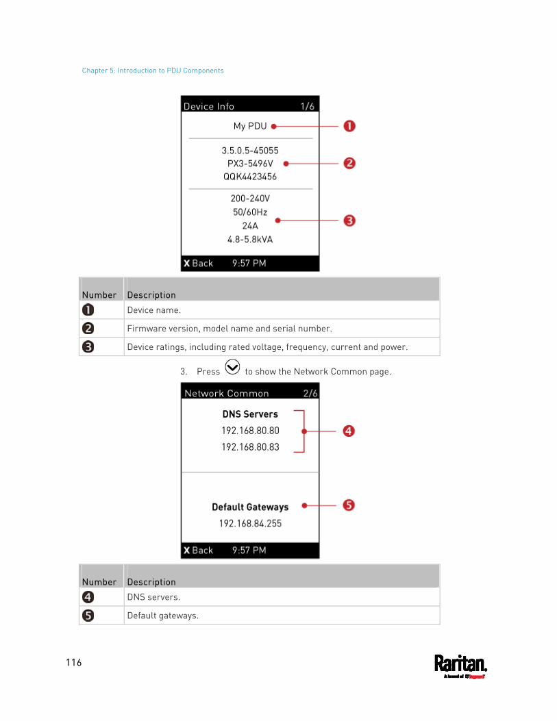
Chapter 5: Introduction to PDU Components
116
Number Description
Device name.
Firmware version, model name and serial number.
Device ratings, including rated voltage, frequency, current and power.
3. Press to show the Network Common page.
Number Description
DNS servers.
Default gateways.
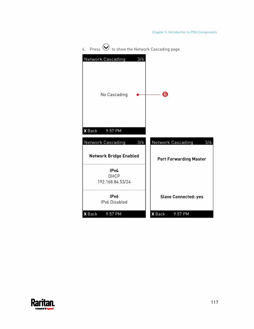
Chapter 5: Introduction to PDU Components
117
4. Press to show the Network Cascading page.
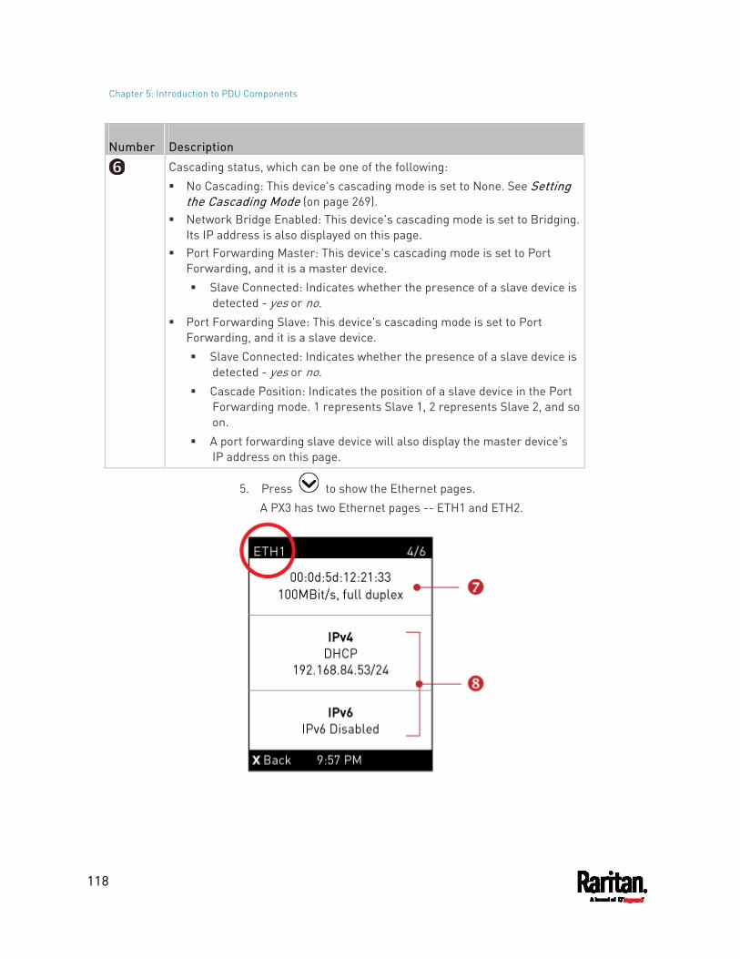
Chapter 5: Introduction to PDU Components
118
Number Description
Cascading status, which can be one of the following: No Cascading: This device's cascading mode is set to None. See Setting
the Cascading Mode (on page 269). Network Bridge Enabled: This device's cascading mode is set to Bridging.
Its IP address is also displayed on this page. Port Forwarding Master: This device's cascading mode is set to Port
Forwarding, and it is a master device. Slave Connected: Indicates whether the presence of a slave device is
detected - yes or no. Port Forwarding Slave: This device's cascading mode is set to Port
Forwarding, and it is a slave device. Slave Connected: Indicates whether the presence of a slave device is
detected - yes or no. Cascade Position: Indicates the position of a slave device in the Port
Forwarding mode. 1 represents Slave 1, 2 represents Slave 2, and so on.
A port forwarding slave device will also display the master device's IP address on this page.
5. Press to show the Ethernet pages. A PX3 has two Ethernet pages -- ETH1 and ETH2.
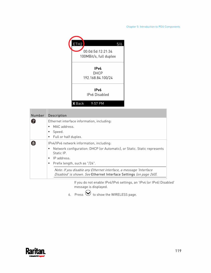
Chapter 5: Introduction to PDU Components
119
Number Description
Ethernet interface information, including: MAC address. Speed. Full or half duplex.
IPv4/IPv6 network information, including: Network configuration: DHCP (or Automatic), or Static. Static represents
Static IP. IP address. Prefix length, such as "/24".
Note: If you disable any Ethernet interface, a message 'Interface Disabled' is shown. See Ethernet Interface Settings (on page 260).
If you do not enable IPv4/IPv6 settings, an 'IPv4 (or IPv6) Disabled' message is displayed.
6. Press to show the WIRELESS page.
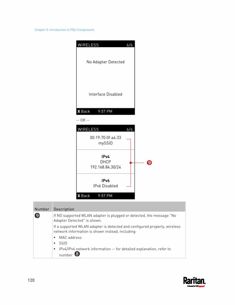
Chapter 5: Introduction to PDU Components
120
-- OR --
Number Description
If NO supported WLAN adapter is plugged or detected, the message "No Adapter Detected" is shown. If a supported WLAN adapter is detected and configured properly, wireless network information is shown instead, including: MAC address SSID IPv4/IPv6 network information -- for detailed explanation, refer to
number
Chapter 5: Introduction to PDU Components
121
7. To return to the Main Menu, press .
Manually Changing the Zero U LCD Orientation
A Zero U model has a tilt sensor that can detect the orientation of its physical device to automatically adjust ts LCD content's orientation.
If the LCD's orientation does not meet your need, you can manually configure it.
The factory default is automatic orientation.
To set up the LCD orientation:
1. Press or simultaneously until you see the LCD shows "Fixed Orientation".
2. If the current LCD orientation does not meet your need, repeat the above step until the orientation you preferred is displayed. If you want to return to the factory default, also repeat step 1
until the LCD shows "Automatic Orientation".
Alerts Notice in a Yellow or Red Screen
In the automatic mode, if an alert occurs, the LCD display automatically shows a yellow or red screen which indicates the total number of alerted sensors and information of the latest transitions.
When all alerted sensors enter the warning levels, the screen's background turns yellow.
When at least one of the alerted sensors enters the critical level or there is any "alarm", the screen's background turns red.
For color definitions, see Yellow- or Red-Highlighted Sensors (on page 214).
The following illustrates the alerts notices in red.
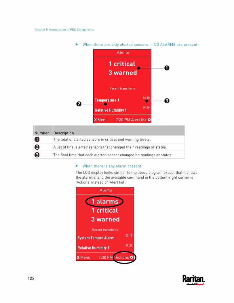
Chapter 5: Introduction to PDU Components
122
When there are only alerted sensors -- NO ALARMS are present:
Number Description
The total of alerted sensors in critical and warning levels.
A list of final alerted sensors that changed their readings or states.
The final time that each alerted sensor changed its readings or states.
When there is any alarm present:
The LCD display looks similar to the above diagram except that it shows the alarm(s) and the available command in the bottom-right corner is 'Actions' instead of 'Alert list'.
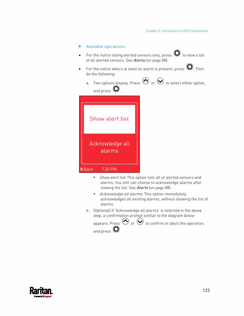
Chapter 5: Introduction to PDU Components
123
Available operations:
For the notice listing alerted sensors only, press to view a list of all alerted sensors. See Alerts (on page 88).
For the notice where at least an alarm is present, press . Then do the following:
a. Two options display. Press or to select either option,
and press .
Show alert list: This option lists all of alerted sensors and
alarms. You still can choose to acknowledge alarms after viewing the list. See Alerts (on page 88).
Acknowledge all alarms: This option immediately acknowledges all existing alarms, without showing the list of alarms.
b. (Optional) If 'Acknowledge all alarms' is selected in the above step, a confirmation prompt similar to the diagram below
appears. Press or to confirm or abort the operation,
and press .
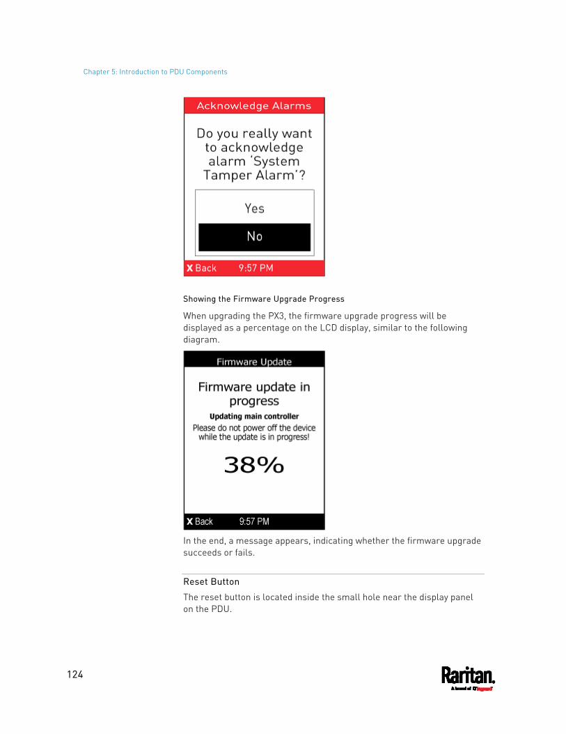
Chapter 5: Introduction to PDU Components
124
Showing the Firmware Upgrade Progress
When upgrading the PX3, the firmware upgrade progress will be displayed as a percentage on the LCD display, similar to the following diagram.
In the end, a message appears, indicating whether the firmware upgrade succeeds or fails.
Reset Button
The reset button is located inside the small hole near the display panel on the PDU.
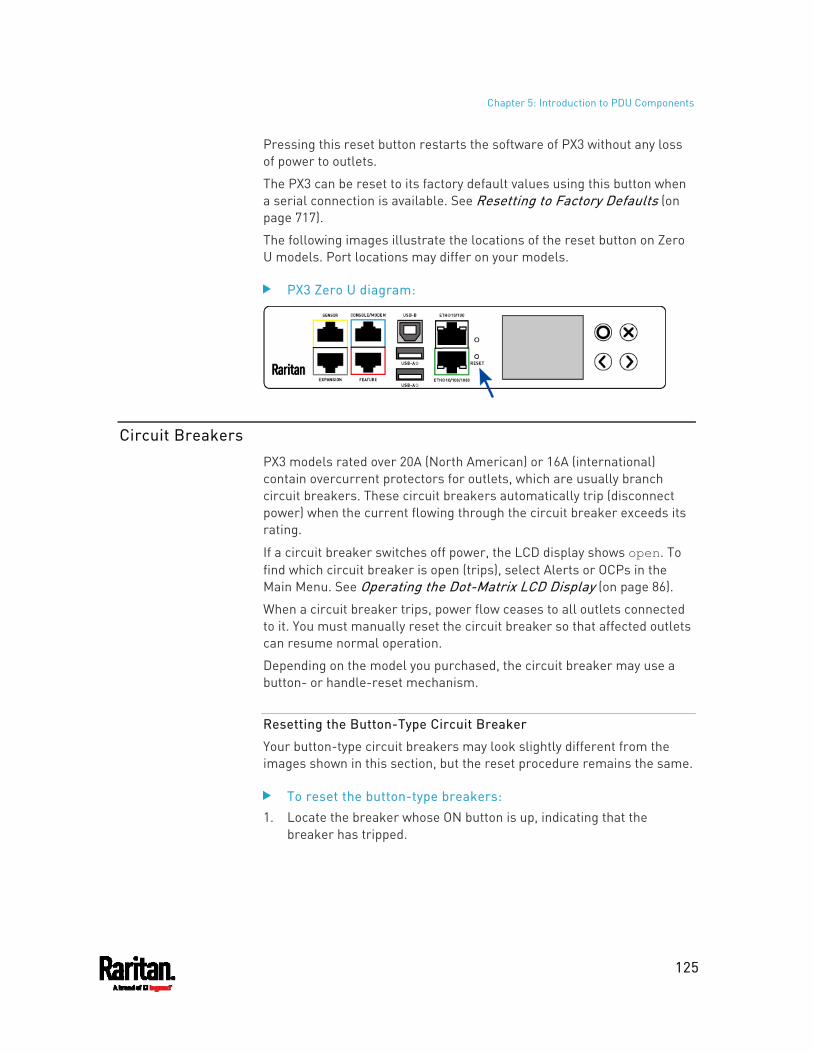
Chapter 5: Introduction to PDU Components
125
Pressing this reset button restarts the software of PX3 without any loss of power to outlets.
The PX3 can be reset to its factory default values using this button when a serial connection is available. See Resetting to Factory Defaults (on page 717).
The following images illustrate the locations of the reset button on Zero U models. Port locations may differ on your models.
PX3 Zero U diagram:
Circuit Breakers
PX3 models rated over 20A (North American) or 16A (international) contain overcurrent protectors for outlets, which are usually branch circuit breakers. These circuit breakers automatically trip (disconnect power) when the current flowing through the circuit breaker exceeds its rating.
If a circuit breaker switches off power, the LCD display shows open. To find which circuit breaker is open (trips), select Alerts or OCPs in the Main Menu. See Operating the Dot-Matrix LCD Display (on page 86).
When a circuit breaker trips, power flow ceases to all outlets connected to it. You must manually reset the circuit breaker so that affected outlets can resume normal operation.
Depending on the model you purchased, the circuit breaker may use a button- or handle-reset mechanism.
Resetting the Button-Type Circuit Breaker
Your button-type circuit breakers may look slightly different from the images shown in this section, but the reset procedure remains the same.
To reset the button-type breakers: 1. Locate the breaker whose ON button is up, indicating that the
breaker has tripped.
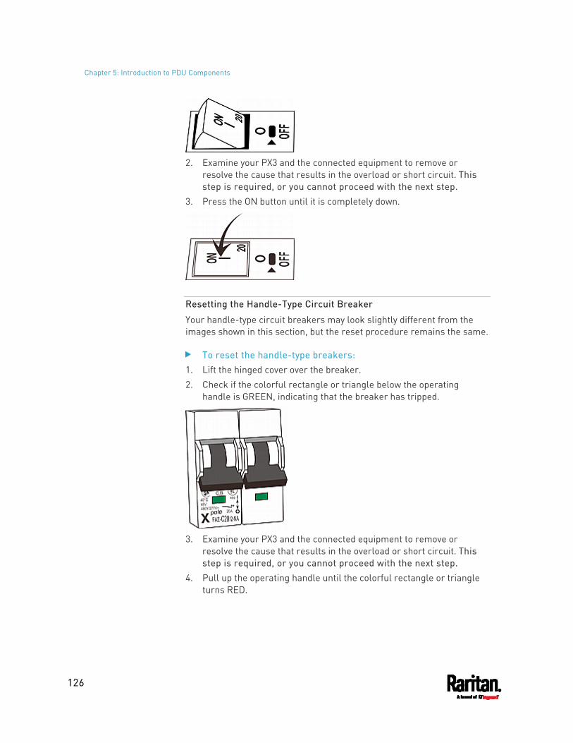
Chapter 5: Introduction to PDU Components
126
2. Examine your PX3 and the connected equipment to remove or
resolve the cause that results in the overload or short circuit. This step is required, or you cannot proceed with the next step.
3. Press the ON button until it is completely down.
Resetting the Handle-Type Circuit Breaker
Your handle-type circuit breakers may look slightly different from the images shown in this section, but the reset procedure remains the same.
To reset the handle-type breakers: 1. Lift the hinged cover over the breaker. 2. Check if the colorful rectangle or triangle below the operating
handle is GREEN, indicating that the breaker has tripped.
3. Examine your PX3 and the connected equipment to remove or
resolve the cause that results in the overload or short circuit. This step is required, or you cannot proceed with the next step.
4. Pull up the operating handle until the colorful rectangle or triangle turns RED.
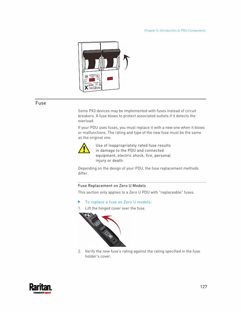
Chapter 5: Introduction to PDU Components
127
Fuse
Some PX3 devices may be implemented with fuses instead of circuit breakers. A fuse blows to protect associated outlets if it detects the overload.
If your PDU uses fuses, you must replace it with a new one when it blows or malfunctions. The rating and type of the new fuse must be the same as the original one.
Use of inappropriately rated fuse results in damage to the PDU and connected equipment, electric shock, fire, personal injury or death.
Depending on the design of your PDU, the fuse replacement methods differ.
Fuse Replacement on Zero U Models
This section only applies to a Zero U PDU with "replaceable" fuses.
To replace a fuse on Zero U models: 1. Lift the hinged cover over the fuse.
2. Verify the new fuse's rating against the rating specified in the fuse
holder's cover.
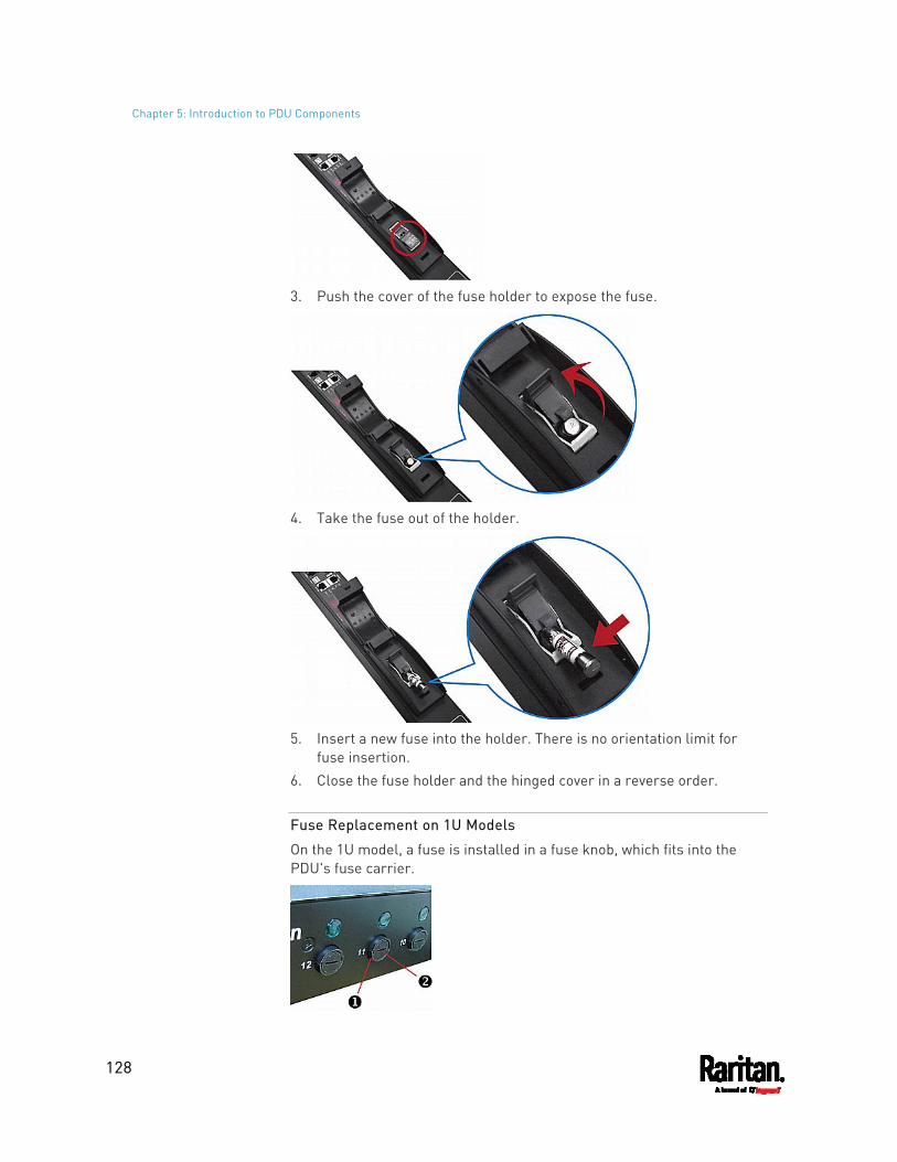
Chapter 5: Introduction to PDU Components
128
3. Push the cover of the fuse holder to expose the fuse.
4. Take the fuse out of the holder.
5. Insert a new fuse into the holder. There is no orientation limit for
fuse insertion. 6. Close the fuse holder and the hinged cover in a reverse order.
Fuse Replacement on 1U Models
On the 1U model, a fuse is installed in a fuse knob, which fits into the PDU's fuse carrier.
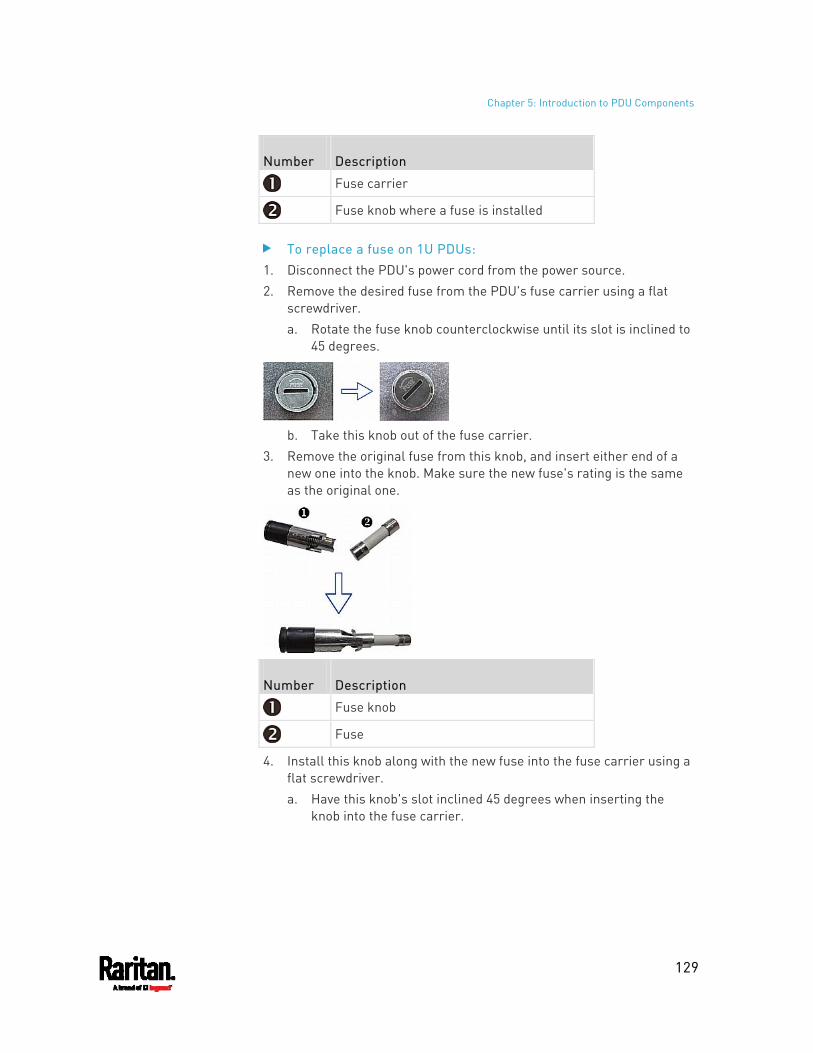
Chapter 5: Introduction to PDU Components
129
Number Description
Fuse carrier
Fuse knob where a fuse is installed
To replace a fuse on 1U PDUs: 1. Disconnect the PDU's power cord from the power source. 2. Remove the desired fuse from the PDU's fuse carrier using a flat
screwdriver. a. Rotate the fuse knob counterclockwise until its slot is inclined to
45 degrees.
b. Take this knob out of the fuse carrier.
3. Remove the original fuse from this knob, and insert either end of a new one into the knob. Make sure the new fuse's rating is the same as the original one.
Number Description
Fuse knob
Fuse
4. Install this knob along with the new fuse into the fuse carrier using a flat screwdriver. a. Have this knob's slot inclined 45 degrees when inserting the
knob into the fuse carrier.
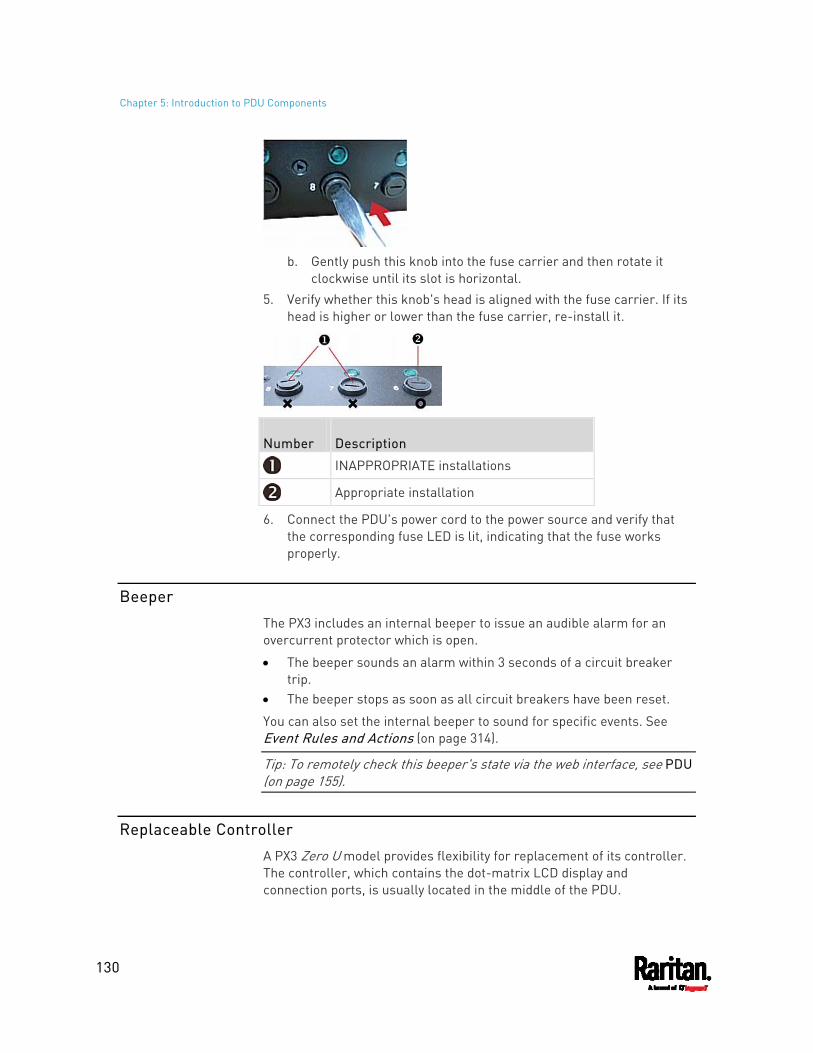
Chapter 5: Introduction to PDU Components
130
b. Gently push this knob into the fuse carrier and then rotate it
clockwise until its slot is horizontal. 5. Verify whether this knob's head is aligned with the fuse carrier. If its
head is higher or lower than the fuse carrier, re-install it.
Number Description
INAPPROPRIATE installations
Appropriate installation
6. Connect the PDU's power cord to the power source and verify that the corresponding fuse LED is lit, indicating that the fuse works properly.
Beeper
The PX3 includes an internal beeper to issue an audible alarm for an overcurrent protector which is open.
The beeper sounds an alarm within 3 seconds of a circuit breaker trip.
The beeper stops as soon as all circuit breakers have been reset.
You can also set the internal beeper to sound for specific events. See Event Rules and Actions (on page 314).
Tip: To remotely check this beeper's state via the web interface, see PDU (on page 155).
Replaceable Controller
A PX3 Zero U model provides flexibility for replacement of its controller. The controller, which contains the dot-matrix LCD display and connection ports, is usually located in the middle of the PDU.

Chapter 5: Introduction to PDU Components
131
If the controller is broken, you can simply send the controller back to Raritan for repair, or purchase a new controller from Raritan.
1U / 2U PDUs and all of PX3-3000 series do NOT support this feature.
To request a new controller:
Contact [email protected] to request a new PX3 controller.
Include these details with your request:
The serial number of the PDU The serial number of the controller board The full model number of the PDU The firmware version that the PDU is running (if known).
To replace a controller: 1. PDU is NOT required to be powered off. 2. Loosen the screws at two sides of the PX3 controller, and lift it up.
Note: Loosen the screws instead of removing them.
3. Disconnect the PDU's controller cable from the controller.
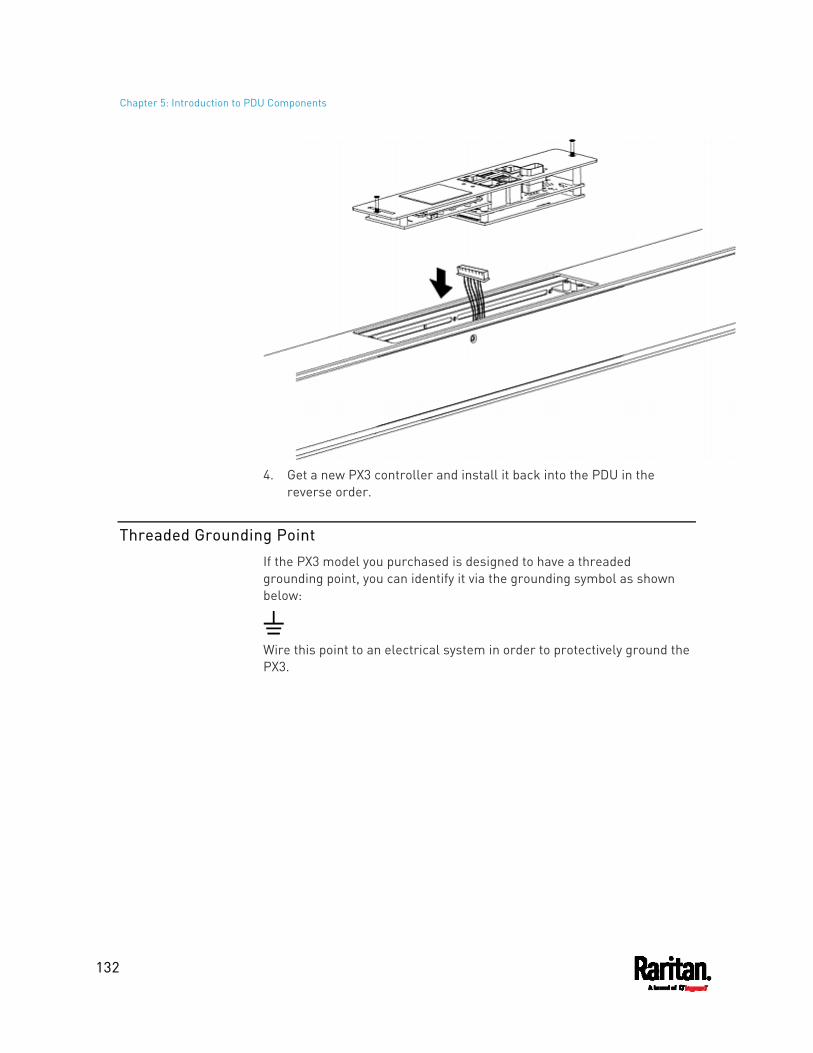
Chapter 5: Introduction to PDU Components
132
4. Get a new PX3 controller and install it back into the PDU in the
reverse order.
Threaded Grounding Point
If the PX3 model you purchased is designed to have a threaded grounding point, you can identify it via the grounding symbol as shown below:
Wire this point to an electrical system in order to protectively ground the PX3.
133
This chapter explains how to use the web interface to administer a PX3.
In This Chapter
Supported Web Browsers ....................................................................... 133 Login, Logout and Password Change ..................................................... 133 Web Interface Overview...........................................................................137 Dashboard ............................................................................................... 145 PDU.......................................................................................................... 155 Inlet.......................................................................................................... 164 Outlets ..................................................................................................... 168 Outlet Groups .......................................................................................... 186 OCPs ........................................................................................................ 199 Peripherals .............................................................................................. 207 Feature Port ............................................................................................ 229 User Management................................................................................... 243 Device Settings ........................................................................................ 254 Maintenance ............................................................................................ 403 Webcam Management............................................................................. 431 SmartLock and Card Reader................................................................... 444
Supported Web Browsers
Internet Explorer® 11 Firefox® 52 and later Safari® (Mac) Google® Chrome® 52 and later Android 4.2 and later iOS 7.0 and later
Login, Logout and Password Change
The first time you log in to the PX3, use the factory default "admin" user credentials. For details, refer to the Quick Setup Guide accompanying the product.
After login, you can create user accounts for other users. See Creating Users (on page 244).
Login
You must enable JavaScript in the web browser for proper operation.
Chapter 6 Using the Web Interface
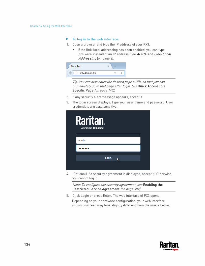
Chapter 6: Using the Web Interface
134
To log in to the web interface: 1. Open a browser and type the IP address of your PX3.
If the link-local addressing has been enabled, you can type pdu.local instead of an IP address. See APIPA and Link-Local Addressing (on page 2).
Tip: You can also enter the desired page's URL so that you can immediately go to that page after login. See Quick Access to a Specific Page (on page 143).
2. If any security alert message appears, accept it. 3. The login screen displays. Type your user name and password. User
credentials are case sensitive.
4. (Optional) If a security agreement is displayed, accept it. Otherwise,
you cannot log in.
Note: To configure the security agreement, see Enabling the Restricted Service Agreement (on page 309).
5. Click Login or press Enter. The web interface of PX3 opens. Depending on your hardware configuration, your web interface shown onscreen may look slightly different from the image below.
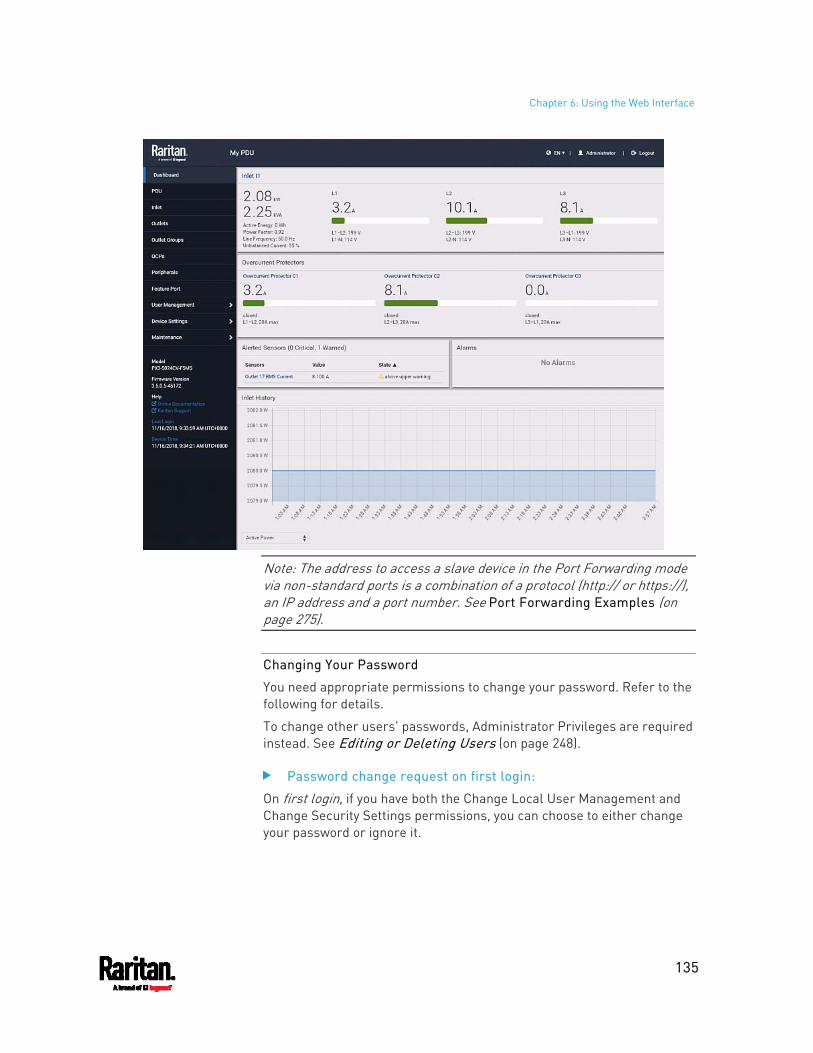
Chapter 6: Using the Web Interface
135
Note: The address to access a slave device in the Port Forwarding mode via non-standard ports is a combination of a protocol (http:// or https://), an IP address and a port number. See Port Forwarding Examples (on page 275).
Changing Your Password
You need appropriate permissions to change your password. Refer to the following for details.
To change other users' passwords, Administrator Privileges are required instead. See Editing or Deleting Users (on page 248).
Password change request on first login:
On first login, if you have both the Change Local User Management and Change Security Settings permissions, you can choose to either change your password or ignore it.
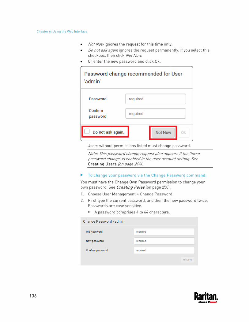
Chapter 6: Using the Web Interface
136
Not Now ignores the request for this time only. Do not ask again ignores the request permanently. If you select this
checkbox, then click Not Now. Or enter the new password and click Ok.
Users without permissions listed must change password.
Note: This password change request also appears if the 'force password change' is enabled in the user account setting. See Creating Users (on page 244).
To change your password via the Change Password command:
You must have the Change Own Password permission to change your own password. See Creating Roles (on page 250).
1. Choose User Management > Change Password. 2. First type the current password, and then the new password twice.
Passwords are case sensitive. A password comprises 4 to 64 characters.
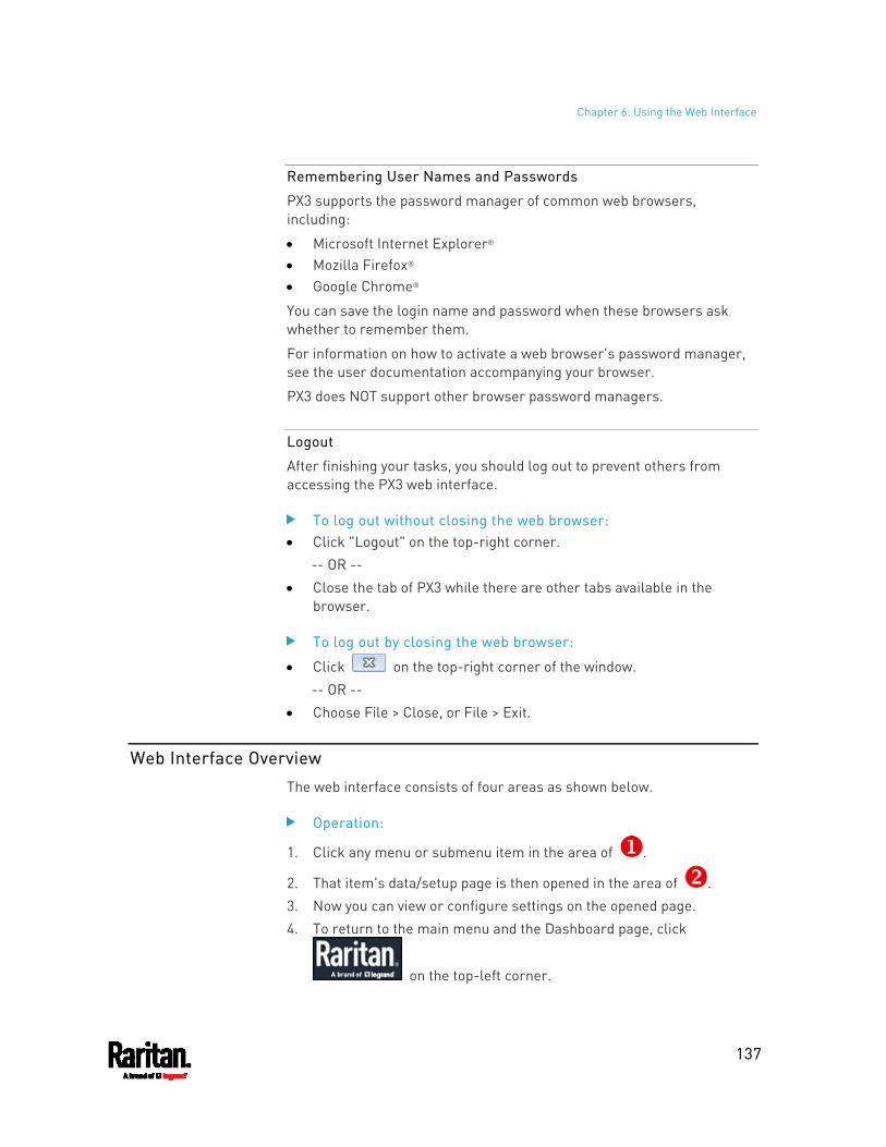
Chapter 6: Using the Web Interface
137
Remembering User Names and Passwords
PX3 supports the password manager of common web browsers, including:
Microsoft Internet Explorer® Mozilla Firefox® Google Chrome®
You can save the login name and password when these browsers ask whether to remember them.
For information on how to activate a web browser's password manager, see the user documentation accompanying your browser.
PX3 does NOT support other browser password managers.
Logout
After finishing your tasks, you should log out to prevent others from accessing the PX3 web interface.
To log out without closing the web browser: Click "Logout" on the top-right corner.
-- OR -- Close the tab of PX3 while there are other tabs available in the
browser.
To log out by closing the web browser:
Click on the top-right corner of the window. -- OR --
Choose File > Close, or File > Exit.
Web Interface Overview
The web interface consists of four areas as shown below.
Operation:
1. Click any menu or submenu item in the area of .
2. That item's data/setup page is then opened in the area of . 3. Now you can view or configure settings on the opened page. 4. To return to the main menu and the Dashboard page, click
on the top-left corner.
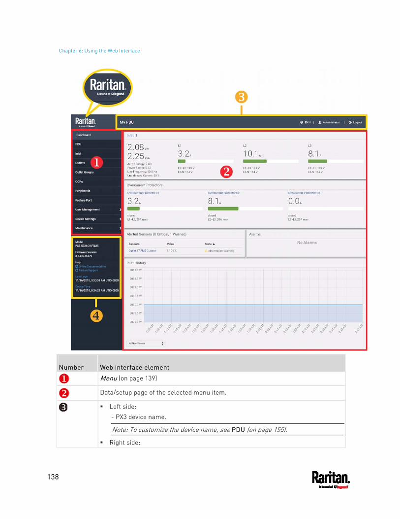
Chapter 6: Using the Web Interface
138
Number Web interface element
Menu (on page 139)
Data/setup page of the selected menu item.
Left side: - PX3 device name.
Note: To customize the device name, see PDU (on page 155).
Right side:
Chapter 6: Using the Web Interface
139
Number Web interface element - Displayed language, which is English (EN) by default. You can change it. - Your login name, which you can click to view your user account settings. - Logout button.
From top to bottom -- Your PX3 model. Current firmware version. Online Documentation: link to the online help of PX3.
- See Browsing through the Online Help (on page 840). Raritan Support: link to Raritan Technical Support webpage. Date and time of your user account's last login.
- Click Last Login to view your login history. PX3 system time, which is converted to the time zone of your computer or
mobile device. - Click Device Time to open the Date/Time setup page.
Menu
Depending on your model and hardware configuration, your PX3 may show all or some menu items shown below.
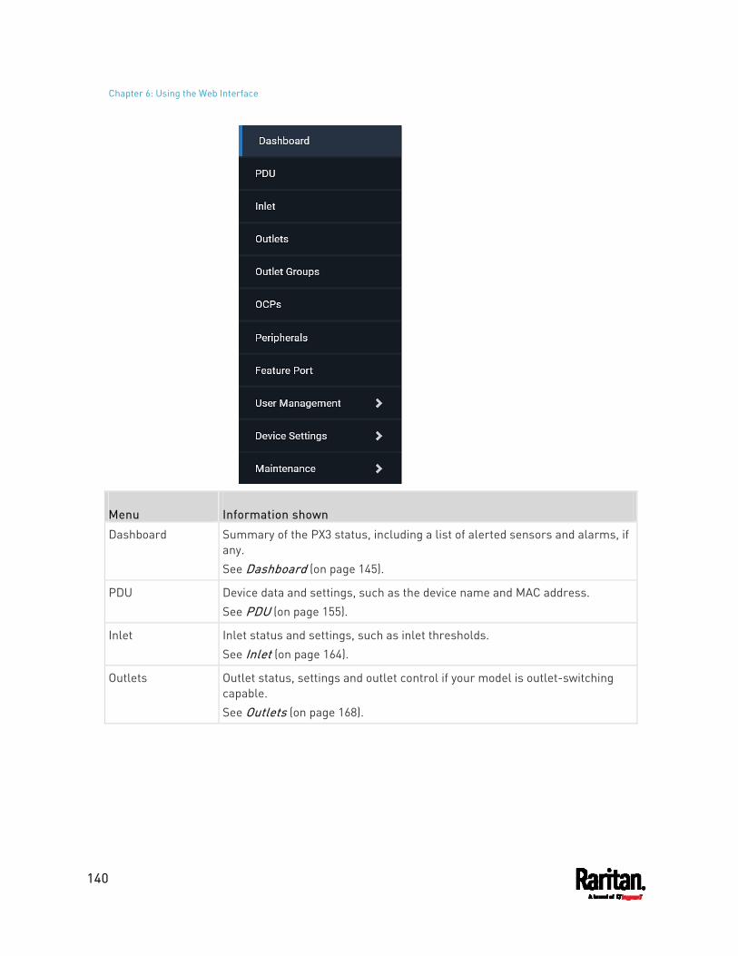
Chapter 6: Using the Web Interface
140
Menu Information shown
Dashboard Summary of the PX3 status, including a list of alerted sensors and alarms, if any. See Dashboard (on page 145).
PDU Device data and settings, such as the device name and MAC address. See PDU (on page 155).
Inlet Inlet status and settings, such as inlet thresholds. See Inlet (on page 164).
Outlets Outlet status, settings and outlet control if your model is outlet-switching capable. See Outlets (on page 168).
Chapter 6: Using the Web Interface
141
Menu Information shown
Outlet Groups Only PDUs with outlet-switching and/or outlet-metering feature show this menu item.
You can create one or multiple groups comprising one or multiple outlets of the same PX3. Functions which you can perform on an outlet group vary depending on the model you purchased. See Outlet Groups (on page 186).
OCPs The OCPs menu item displays only when there are overcurrent protectors implemented on your model.
OCP status and settings, such as OCP thresholds. See OCPs (on page 199).
Peripherals Status and settings of Raritan environmental sensor packages, if connected.See Peripherals (on page 207).
Feature Port
The name 'Feature Port(s)' will be replaced with one of the device names listed to the right
Status and settings of the device connected to the Feature port(s), which can be one of the following. Asset Strip External Beeper LHX 20 SHX 30 LHX 40 Power CIM See Feature Port (on page 229).
Webcams The 'Webcams' menu item appears when there is any webcam(s) connected to the PX3, or when there are snapshots saved onto the PX3 already.
Webcam live snapshots/video and webcam settings.
See Webcam Management (on page 431).
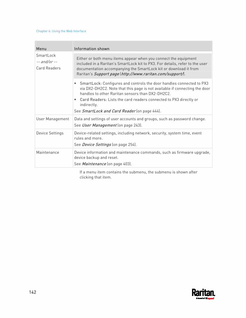
Chapter 6: Using the Web Interface
142
Menu Information shown
SmartLock -- and/or -- Card Readers
Either or both menu items appear when you connect the equipment included in a Raritan's SmartLock kit to PX3. For details, refer to the user documentation accompanying the SmartLock kit or download it from Raritan's Support page (http://www.raritan.com/support/).
SmartLock: Configures and controls the door handles connected to PX3 via DX2-DH2C2. Note that this page is not available if connecting the door handles to other Raritan sensors than DX2-DH2C2.
Card Readers: Lists the card readers connected to PX3 directly or indirectly.
See SmartLock and Card Reader (on page 444).
User Management Data and settings of user accounts and groups, such as password change. See User Management (on page 243).
Device Settings Device-related settings, including network, security, system time, event rules and more. See Device Settings (on page 254).
Maintenance Device information and maintenance commands, such as firmware upgrade, device backup and reset. See Maintenance (on page 403).
If a menu item contains the submenu, the submenu is shown after clicking that item.
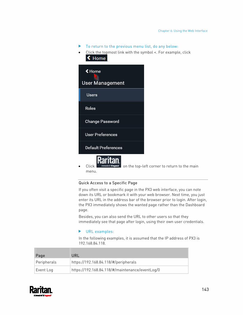
Chapter 6: Using the Web Interface
143
To return to the previous menu list, do any below: Click the topmost link with the symbol <. For example, click
.
Click on the top-left corner to return to the main menu.
Quick Access to a Specific Page
If you often visit a specific page in the PX3 web interface, you can note down its URL or bookmark it with your web browser. Next time, you just enter its URL in the address bar of the browser prior to login. After login, the PX3 immediately shows the wanted page rather than the Dashboard page.
Besides, you can also send the URL to other users so that they immediately see that page after login, using their own user credentials.
URL examples:
In the following examples, it is assumed that the IP address of PX3 is 192.168.84.118.
Page URL
Peripherals https://192.168.84.118/#/peripherals
Event Log https://192.168.84.118/#/maintenance/eventLog/0
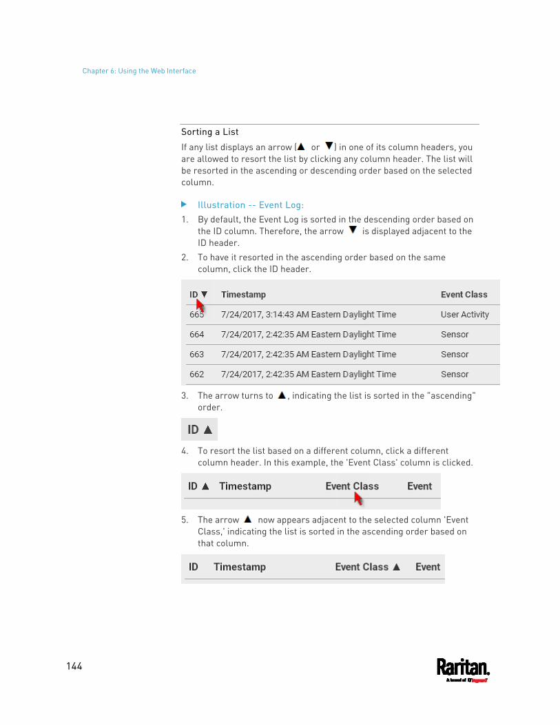
Chapter 6: Using the Web Interface
144
Sorting a List
If any list displays an arrow ( or ) in one of its column headers, you are allowed to resort the list by clicking any column header. The list will be resorted in the ascending or descending order based on the selected column.
Illustration -- Event Log: 1. By default, the Event Log is sorted in the descending order based on
the ID column. Therefore, the arrow is displayed adjacent to the ID header.
2. To have it resorted in the ascending order based on the same column, click the ID header.
3. The arrow turns to , indicating the list is sorted in the "ascending"
order.
4. To resort the list based on a different column, click a different
column header. In this example, the 'Event Class' column is clicked.
5. The arrow now appears adjacent to the selected column 'Event
Class,' indicating the list is sorted in the ascending order based on that column.
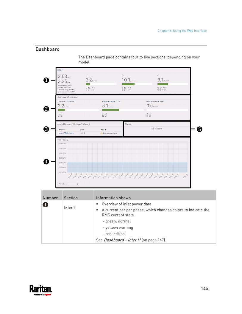
Chapter 6: Using the Web Interface
145
Dashboard
The Dashboard page contains four to five sections, depending on your model.
Number Section Information shown
Inlet I1 Overview of inlet power data A current bar per phase, which changes colors to indicate the
RMS current state - green: normal - yellow: warning - red: critical
See Dashboard - Inlet I1 (on page 147).
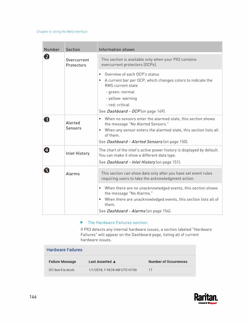
Chapter 6: Using the Web Interface
146
Number Section Information shown
Overcurrent Protectors
This section is available only when your PX3 contains overcurrent protectors (OCPs).
Overview of each OCP's status A current bar per OCP, which changes colors to indicate the
RMS current state - green: normal - yellow: warning - red: critical
See Dashboard - OCP (on page 149).
Alerted Sensors
When no sensors enter the alarmed state, this section shows the message "No Alerted Sensors."
When any sensor enters the alarmed state, this section lists all of them.
See Dashboard - Alerted Sensors (on page 150).
Inlet History The chart of the inlet's active power history is displayed by default. You can make it show a different data type.
See Dashboard - Inlet History (on page 151).
Alarms This section can show data only after you have set event rules requiring users to take the acknowledgment action.
When there are no unacknowledged events, this section shows the message "No Alarms."
When there are unacknowledged events, this section lists all of them.
See Dashboard - Alarms (on page 154).
The Hardware Failures section:
If PX3 detects any internal hardware issues, a section labeled "Hardware Failures" will appear on the Dashboard page, listing all of current hardware issues.
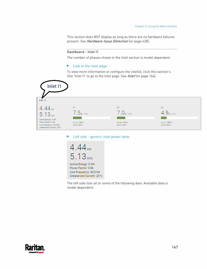
Chapter 6: Using the Web Interface
147
This section does NOT display as long as there are no hardware failures present. See Hardware Issue Detection (on page 428).
Dashboard - Inlet I1
The number of phases shown in the Inlet section is model dependent.
Link to the Inlet page:
To view more information or configure the inlet(s), click this section's title 'Inlet I1' to go to the Inlet page. See Inlet (on page 164).
Left side - generic inlet power data:
The left side lists all or some of the following data. Available data is model dependent.
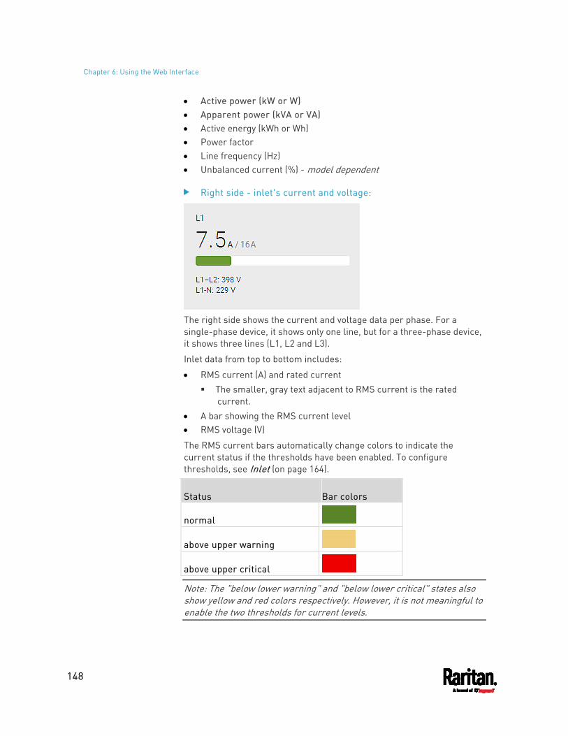
Chapter 6: Using the Web Interface
148
Active power (kW or W) Apparent power (kVA or VA) Active energy (kWh or Wh) Power factor Line frequency (Hz) Unbalanced current (%) - model dependent
Right side - inlet's current and voltage:
The right side shows the current and voltage data per phase. For a single-phase device, it shows only one line, but for a three-phase device, it shows three lines (L1, L2 and L3).
Inlet data from top to bottom includes:
RMS current (A) and rated current The smaller, gray text adjacent to RMS current is the rated
current. A bar showing the RMS current level RMS voltage (V)
The RMS current bars automatically change colors to indicate the current status if the thresholds have been enabled. To configure thresholds, see Inlet (on page 164).
Status Bar colors
normal
above upper warning
above upper critical
Note: The "below lower warning" and "below lower critical" states also show yellow and red colors respectively. However, it is not meaningful to enable the two thresholds for current levels.
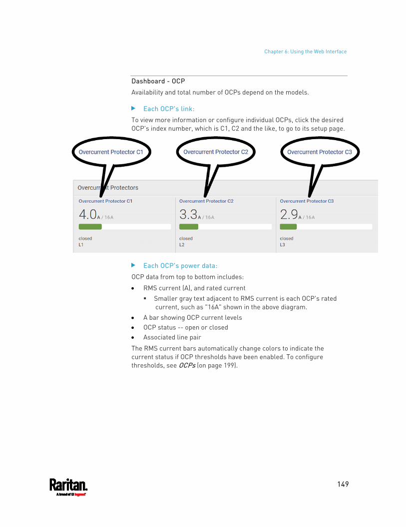
Chapter 6: Using the Web Interface
149
Dashboard - OCP
Availability and total number of OCPs depend on the models.
Each OCP's link:
To view more information or configure individual OCPs, click the desired OCP's index number, which is C1, C2 and the like, to go to its setup page.
Each OCP's power data:
OCP data from top to bottom includes:
RMS current (A), and rated current Smaller gray text adjacent to RMS current is each OCP's rated
current, such as "16A" shown in the above diagram. A bar showing OCP current levels OCP status -- open or closed Associated line pair
The RMS current bars automatically change colors to indicate the current status if OCP thresholds have been enabled. To configure thresholds, see OCPs (on page 199).
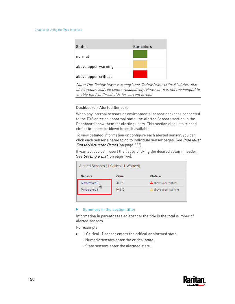
Chapter 6: Using the Web Interface
150
Status Bar colors
normal
above upper warning
above upper critical
Note: The "below lower warning" and "below lower critical" states also show yellow and red colors respectively. However, it is not meaningful to enable the two thresholds for current levels.
Dashboard - Alerted Sensors
When any internal sensors or environmental sensor packages connected to the PX3 enter an abnormal state, the Alerted Sensors section in the Dashboard show them for alerting users. This section also lists tripped circuit breakers or blown fuses, if available.
To view detailed information or configure each alerted sensor, you can click each sensor's name to go to individual sensor pages. See Individual Sensor/Actuator Pages (on page 222).
If wanted, you can resort the list by clicking the desired column header. See Sorting a List (on page 144).
Summary in the section title:
Information in parentheses adjacent to the title is the total number of alerted sensors.
For example:
1 Critical: 1 sensor enters the critical or alarmed state. - Numeric sensors enter the critical state. - State sensors enter the alarmed state.
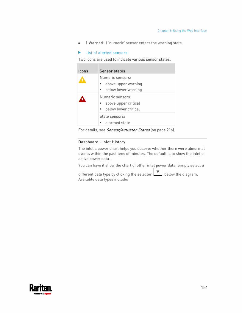
Chapter 6: Using the Web Interface
151
1 Warned: 1 'numeric' sensor enters the warning state.
List of alerted sensors:
Two icons are used to indicate various sensor states.
Icons Sensor states
Numeric sensors: above upper warning below lower warning
Numeric sensors: above upper critical below lower critical
State sensors: alarmed state
For details, see Sensor/Actuator States (on page 216).
Dashboard - Inlet History
The inlet's power chart helps you observe whether there were abnormal events within the past tens of minutes. The default is to show the inlet's active power data.
You can have it show the chart of other inlet power data. Simply select a
different data type by clicking the selector below the diagram. Available data types include:
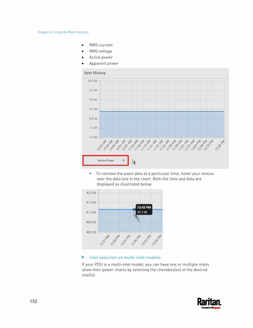
Chapter 6: Using the Web Interface
152
RMS current RMS voltage Active power Apparent power
To retrieve the exact data at a particular time, hover your mouse
over the data line in the chart. Both the time and data are displayed as illustrated below.
Inlet selection on multi-inlet models:
If your PDU is a multi-inlet model, you can have one or multiple inlets show their power charts by selecting the checkbox(es) of the desired inlet(s).
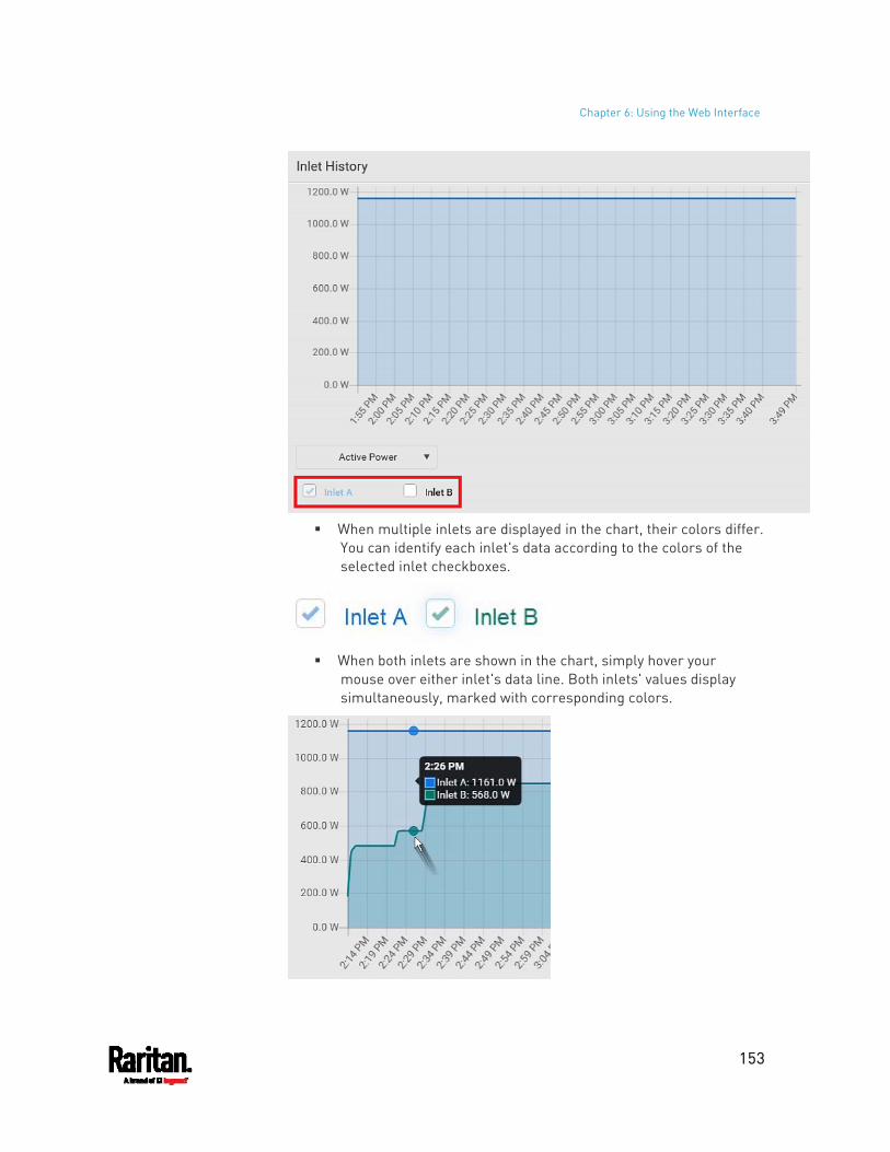
Chapter 6: Using the Web Interface
153
When multiple inlets are displayed in the chart, their colors differ.
You can identify each inlet's data according to the colors of the selected inlet checkboxes.
When both inlets are shown in the chart, simply hover your
mouse over either inlet's data line. Both inlets' values display simultaneously, marked with corresponding colors.
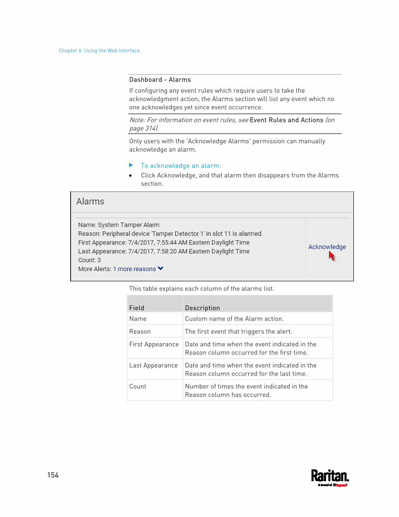
Chapter 6: Using the Web Interface
154
Dashboard - Alarms
If configuring any event rules which require users to take the acknowledgment action, the Alarms section will list any event which no one acknowledges yet since event occurrence.
Note: For information on event rules, see Event Rules and Actions (on page 314).
Only users with the 'Acknowledge Alarms' permission can manually acknowledge an alarm.
To acknowledge an alarm: Click Acknowledge, and that alarm then disappears from the Alarms
section.
This table explains each column of the alarms list.
Field Description
Name Custom name of the Alarm action.
Reason The first event that triggers the alert.
First Appearance Date and time when the event indicated in the Reason column occurred for the first time.
Last Appearance Date and time when the event indicated in the Reason column occurred for the last time.
Count Number of times the event indicated in the Reason column has occurred.
Chapter 6: Using the Web Interface
155
Field Description
More Alerts This field appears only when there are more than one types of events triggering this alert.
If there are other types of events (that is, other reasons) triggering the same alert, the total number of additional reasons is displayed. You can click it to view a list of all events.
The date and time shown on the PX3 web interface are automatically converted to your computer's time zone. To avoid time confusion, it is suggested to apply the same time zone settings as those of PX3 to your computer or mobile device.
Tip: You can also acknowledge all alarms by operating the LCD display. Refer to Alerts Notice in a Yellow or Red Screen (on page 121).
PDU
The PX3 device's generic information and PDU settings are available on the PDU page.
To open the PDU page, click 'PDU' in the Menu (on page 139).
Device information shown: Firmware version Serial number MAC address Rating Internal beeper state (on page 159) Status of +12V power supply sensor (on page 163)
To configure global settings: 1. Click Edit Settings.
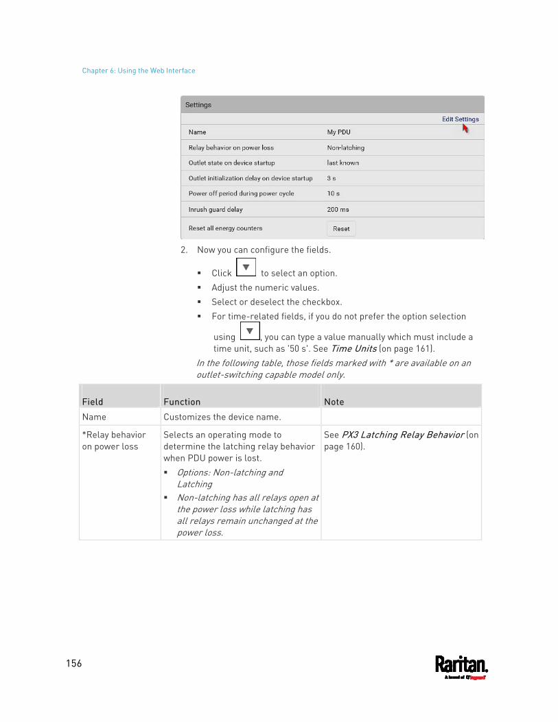
Chapter 6: Using the Web Interface
156
2. Now you can configure the fields.
Click to select an option. Adjust the numeric values. Select or deselect the checkbox. For time-related fields, if you do not prefer the option selection
using , you can type a value manually which must include a time unit, such as '50 s'. See Time Units (on page 161).
In the following table, those fields marked with * are available on an outlet-switching capable model only.
Field Function Note
Name Customizes the device name.
*Relay behavior on power loss
Selects an operating mode to determine the latching relay behavior when PDU power is lost. Options: Non-latching and
Latching Non-latching has all relays open at
the power loss while latching has all relays remain unchanged at the power loss.
See PX3 Latching Relay Behavior (on page 160).
Chapter 6: Using the Web Interface
157
Field Function Note
*Outlet state on device startup (for non-latching mode only)
Determines the initial power state of ALL outlets after the PX3 powers up. Options: on, off, and last known See Options for Outlet State on Startup (on page 160).
After removing power from the PDU, you must wait for a minimum of 10 seconds before powering it up again. Otherwise, the default outlet state settings may not work properly.
You can override the global outlet state setting on a per-outlet basis so specific outlets behave differently on startup. See Individual Outlet Pages (on page 179).
This setting works only when 'Relay behavior on power loss' is set to Non-latching. This is because all relays keep their states unchanged in the latching mode when power is lost and when power is restored.
*Outlet initialization delay on device startup (for non-latching mode only)
Determines how long the PX3 waits before providing power to all outlets during power cycling or after recovering from a temporary power loss. Range: 1 second to 1 hour
See Initialization Delay Use Cases (on page 161).
This setting works only when 'Relay behavior on power loss' is set to Non-latching. This is because all relays keep their states unchanged in the latching mode when power is lost and when power is restored.
*Power off period during power cycle
Determines the power-off period after the outlet is switched OFF during a power cycle. Range: 1 second to 1 hour
Power cycling the outlet(s) turns the outlet(s) off and then back on.
You can override this global power cycle setting on a per-outlet basis so specific outlets' power-off period is different. See Individual Outlet Pages (on page 179).
*Inrush guard delay
Prevents a circuit breaker trip due to inrush current when many devices connected to the PDU are turned on. Range: 100 milliseconds to 10
seconds
See Inrush Current and Inrush Guard Delay (on page 161).
3. Click Save.
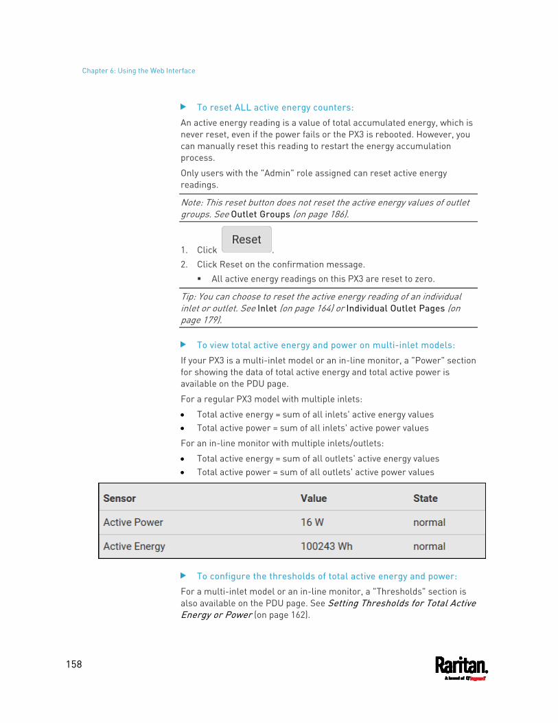
Chapter 6: Using the Web Interface
158
To reset ALL active energy counters:
An active energy reading is a value of total accumulated energy, which is never reset, even if the power fails or the PX3 is rebooted. However, you can manually reset this reading to restart the energy accumulation process.
Only users with the "Admin" role assigned can reset active energy readings.
Note: This reset button does not reset the active energy values of outlet groups. See Outlet Groups (on page 186).
1. Click . 2. Click Reset on the confirmation message.
All active energy readings on this PX3 are reset to zero.
Tip: You can choose to reset the active energy reading of an individual inlet or outlet. See Inlet (on page 164) or Individual Outlet Pages (on page 179).
To view total active energy and power on multi-inlet models:
If your PX3 is a multi-inlet model or an in-line monitor, a "Power" section for showing the data of total active energy and total active power is available on the PDU page.
For a regular PX3 model with multiple inlets:
Total active energy = sum of all inlets' active energy values Total active power = sum of all inlets' active power values
For an in-line monitor with multiple inlets/outlets:
Total active energy = sum of all outlets' active energy values Total active power = sum of all outlets' active power values
To configure the thresholds of total active energy and power:
For a multi-inlet model or an in-line monitor, a "Thresholds" section is also available on the PDU page. See Setting Thresholds for Total Active Energy or Power (on page 162).
Chapter 6: Using the Web Interface
159
Internal Beeper State
The PDU page indicates the internal beeper state.
Available beeper states:
States Description
Off The beeper is turned off.
The beeper is turned on. Active
"Activation Reason" is displayed, indicating why the beeper sounds an alarm.
For example, if the beeper is turned on because of a specific event rule "XXX," the activation reason looks like: Event Action triggered by rule: XXX
Scenarios when the beeper sounds an alarm: Any overcurrent protector on the PX3, including fuses and circuit
breakers, has tripped or blown. See Beeper (on page 130). You have set an event rule that turns on the internal beeper when a
specific event occurs, and that event occurs now. See Event Rules and Actions (on page 314).
On the PX3 supporting residual current monitoring (RCM), the beeper also sounds when an RCM alarm is detected. Note that only the RCM sensor will cause the PDU to beep while RCM "DC" sensor does not cause the PDU to beep regardless of its sensor state. For details, see PX3 Models with Residual Current Monitoring (on page 720).
Tip: To check the internal beeper state via CLI, see PDU Configuration (on page 472).
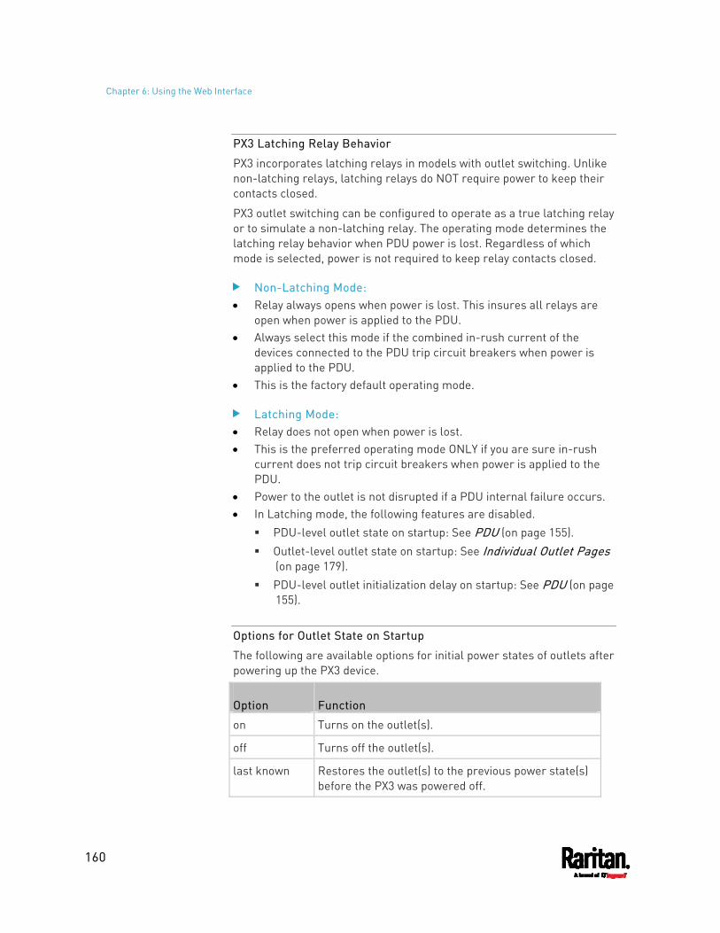
Chapter 6: Using the Web Interface
160
PX3 Latching Relay Behavior
PX3 incorporates latching relays in models with outlet switching. Unlike non-latching relays, latching relays do NOT require power to keep their contacts closed.
PX3 outlet switching can be configured to operate as a true latching relay or to simulate a non-latching relay. The operating mode determines the latching relay behavior when PDU power is lost. Regardless of which mode is selected, power is not required to keep relay contacts closed.
Non-Latching Mode: Relay always opens when power is lost. This insures all relays are
open when power is applied to the PDU. Always select this mode if the combined in-rush current of the
devices connected to the PDU trip circuit breakers when power is applied to the PDU.
This is the factory default operating mode.
Latching Mode: Relay does not open when power is lost. This is the preferred operating mode ONLY if you are sure in-rush
current does not trip circuit breakers when power is applied to the PDU.
Power to the outlet is not disrupted if a PDU internal failure occurs. In Latching mode, the following features are disabled.
PDU-level outlet state on startup: See PDU (on page 155). Outlet-level outlet state on startup: See Individual Outlet Pages
(on page 179). PDU-level outlet initialization delay on startup: See PDU (on page
155).
Options for Outlet State on Startup
The following are available options for initial power states of outlets after powering up the PX3 device.
Option Function
on Turns on the outlet(s).
off Turns off the outlet(s).
last known Restores the outlet(s) to the previous power state(s) before the PX3 was powered off.
Chapter 6: Using the Web Interface
161
If you are configuring an individual outlet on Individual Outlet Pages (on page 179), there is one more outlet state option.
Additional option
Function
PDU defined (xxx)
Follows the global outlet state setting, which is set on PDU (on page 155). The value xxx in parentheses is the currently-selected global option - on, off, or last known.
Initialization Delay Use Cases
Apply the initialization delay in either of the following scenarios.
When power may not initially be stable after being restored When UPS batteries may be charging
Tip: When there are a large number of outlets, set the value to a smaller number to avoid a long wait before all outlets are available.
Inrush Current and Inrush Guard Delay
Inrush current:
When electrical devices are turned on, they can initially draw a very large current known as inrush current. Inrush current typically lasts for 20-40 milliseconds.
Inrush guard delay:
The inrush guard delay feature helps prevent a circuit breaker trip due to the combined inrush current of many devices turned on at the same time.
For example, if the inrush guard delay is set to 100 milliseconds and two or more outlets are turned on at the same time, the PDU will sequentially turn the outlets on with a 100 millisecond delay occurring between each one.
Time Units
If you choose to type a new value in the time-related fields, such as the Inrush Guard Delay field, you must add a time unit after the numeric value. For example, you can type '15 s' for 15 seconds.
Note that different fields have different range of valid values.
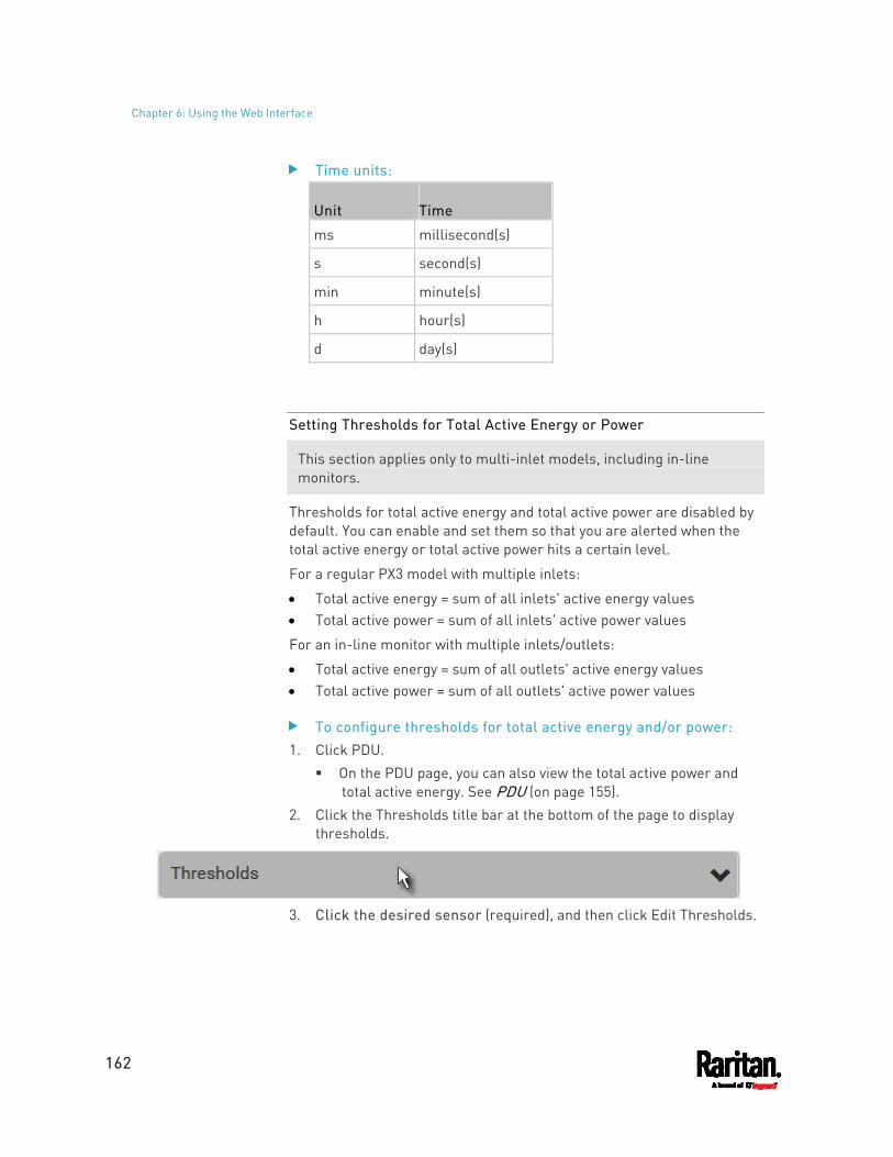
Chapter 6: Using the Web Interface
162
Time units:
Unit Time
ms millisecond(s)
s second(s)
min minute(s)
h hour(s)
d day(s)
Setting Thresholds for Total Active Energy or Power
This section applies only to multi-inlet models, including in-line monitors.
Thresholds for total active energy and total active power are disabled by default. You can enable and set them so that you are alerted when the total active energy or total active power hits a certain level.
For a regular PX3 model with multiple inlets:
Total active energy = sum of all inlets' active energy values Total active power = sum of all inlets' active power values
For an in-line monitor with multiple inlets/outlets:
Total active energy = sum of all outlets' active energy values Total active power = sum of all outlets' active power values
To configure thresholds for total active energy and/or power: 1. Click PDU.
On the PDU page, you can also view the total active power and total active energy. See PDU (on page 155).
2. Click the Thresholds title bar at the bottom of the page to display thresholds.
3. Click the desired sensor (required), and then click Edit Thresholds.
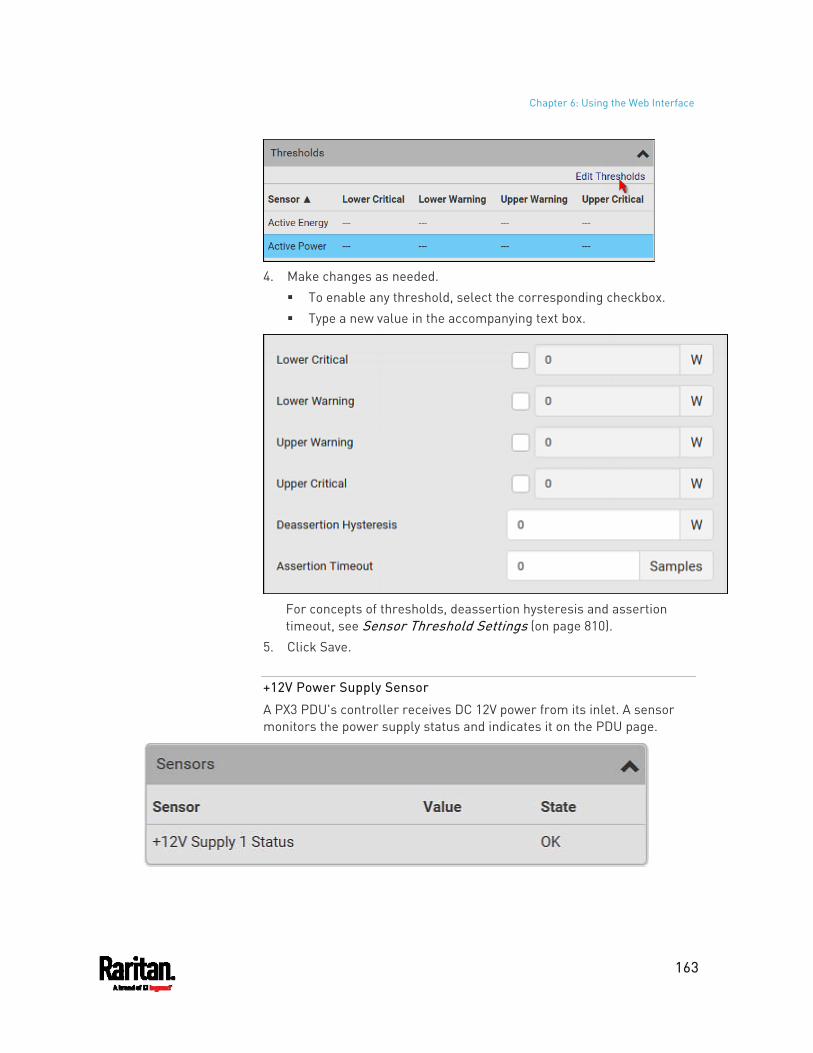
Chapter 6: Using the Web Interface
163
4. Make changes as needed.
To enable any threshold, select the corresponding checkbox. Type a new value in the accompanying text box.
For concepts of thresholds, deassertion hysteresis and assertion timeout, see Sensor Threshold Settings (on page 810).
5. Click Save.
+12V Power Supply Sensor
A PX3 PDU's controller receives DC 12V power from its inlet. A sensor monitors the power supply status and indicates it on the PDU page.
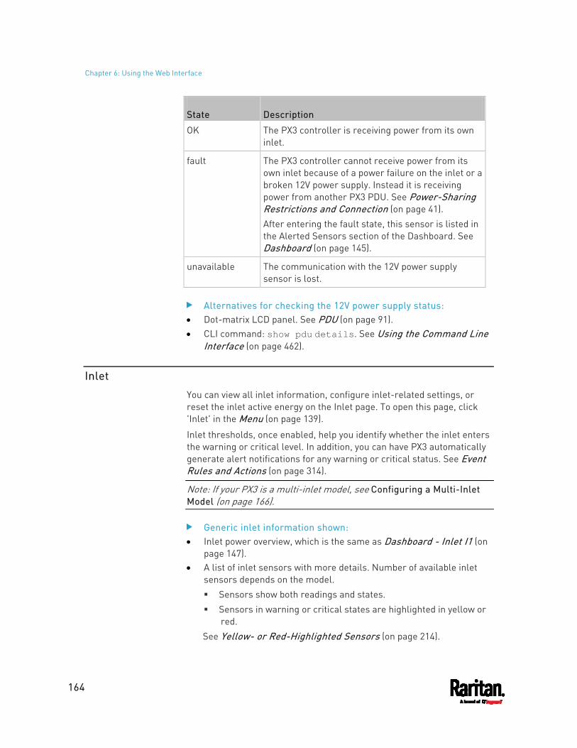
Chapter 6: Using the Web Interface
164
State Description
OK The PX3 controller is receiving power from its own inlet.
fault The PX3 controller cannot receive power from its own inlet because of a power failure on the inlet or a broken 12V power supply. Instead it is receiving power from another PX3 PDU. See Power-Sharing Restrictions and Connection (on page 41). After entering the fault state, this sensor is listed in the Alerted Sensors section of the Dashboard. See Dashboard (on page 145).
unavailable The communication with the 12V power supply sensor is lost.
Alternatives for checking the 12V power supply status: Dot-matrix LCD panel. See PDU (on page 91). CLI command: show pdu details. See Using the Command Line
Interface (on page 462).
Inlet
You can view all inlet information, configure inlet-related settings, or reset the inlet active energy on the Inlet page. To open this page, click 'Inlet' in the Menu (on page 139).
Inlet thresholds, once enabled, help you identify whether the inlet enters the warning or critical level. In addition, you can have PX3 automatically generate alert notifications for any warning or critical status. See Event Rules and Actions (on page 314).
Note: If your PX3 is a multi-inlet model, see Configuring a Multi-Inlet Model (on page 166).
Generic inlet information shown: Inlet power overview, which is the same as Dashboard - Inlet I1 (on
page 147). A list of inlet sensors with more details. Number of available inlet
sensors depends on the model. Sensors show both readings and states. Sensors in warning or critical states are highlighted in yellow or
red. See Yellow- or Red-Highlighted Sensors (on page 214).
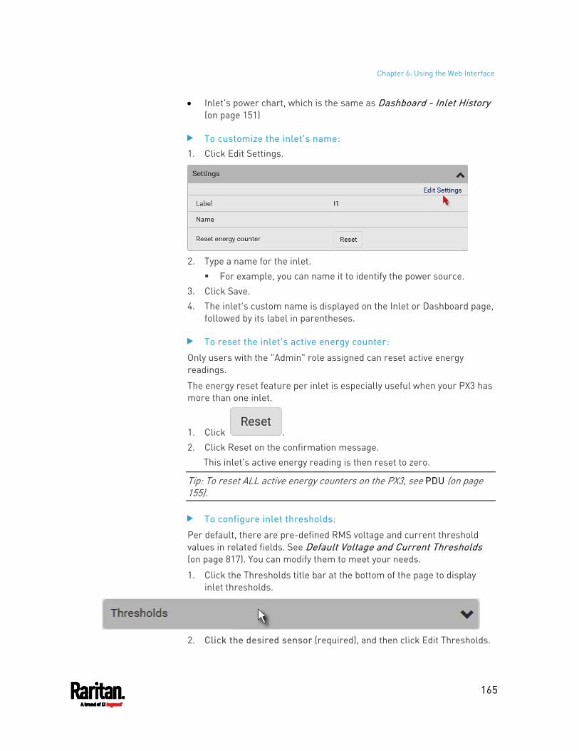
Chapter 6: Using the Web Interface
165
Inlet's power chart, which is the same as Dashboard - Inlet History (on page 151)
To customize the inlet's name: 1. Click Edit Settings.
2. Type a name for the inlet.
For example, you can name it to identify the power source. 3. Click Save. 4. The inlet's custom name is displayed on the Inlet or Dashboard page,
followed by its label in parentheses.
To reset the inlet's active energy counter:
Only users with the "Admin" role assigned can reset active energy readings.
The energy reset feature per inlet is especially useful when your PX3 has more than one inlet.
1. Click . 2. Click Reset on the confirmation message.
This inlet's active energy reading is then reset to zero.
Tip: To reset ALL active energy counters on the PX3, see PDU (on page 155).
To configure inlet thresholds:
Per default, there are pre-defined RMS voltage and current threshold values in related fields. See Default Voltage and Current Thresholds (on page 817). You can modify them to meet your needs.
1. Click the Thresholds title bar at the bottom of the page to display inlet thresholds.
2. Click the desired sensor (required), and then click Edit Thresholds.
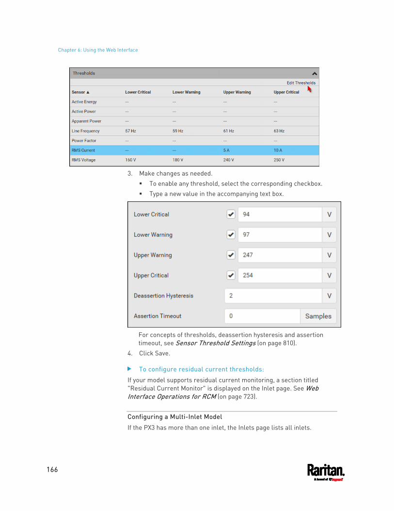
Chapter 6: Using the Web Interface
166
3. Make changes as needed.
To enable any threshold, select the corresponding checkbox. Type a new value in the accompanying text box.
For concepts of thresholds, deassertion hysteresis and assertion timeout, see Sensor Threshold Settings (on page 810).
4. Click Save.
To configure residual current thresholds:
If your model supports residual current monitoring, a section titled "Residual Current Monitor" is displayed on the Inlet page. See Web Interface Operations for RCM (on page 723).
Configuring a Multi-Inlet Model
If the PX3 has more than one inlet, the Inlets page lists all inlets.
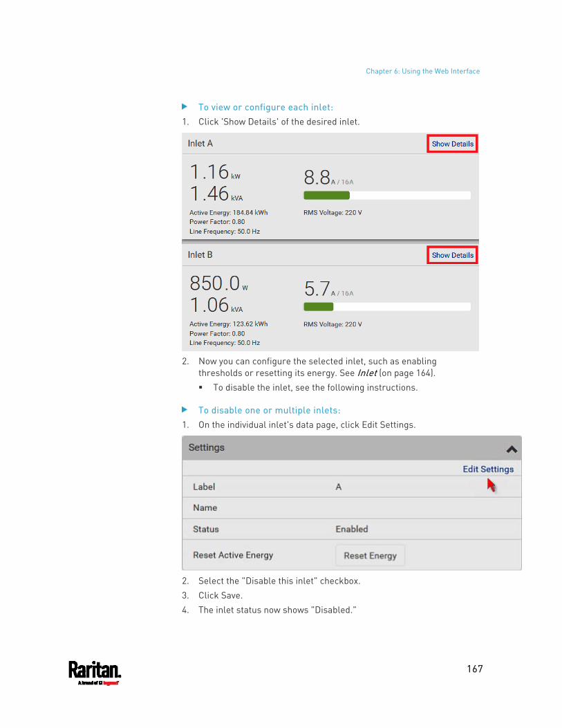
Chapter 6: Using the Web Interface
167
To view or configure each inlet: 1. Click 'Show Details' of the desired inlet.
2. Now you can configure the selected inlet, such as enabling
thresholds or resetting its energy. See Inlet (on page 164). To disable the inlet, see the following instructions.
To disable one or multiple inlets: 1. On the individual inlet's data page, click Edit Settings.
2. Select the "Disable this inlet" checkbox. 3. Click Save. 4. The inlet status now shows "Disabled."
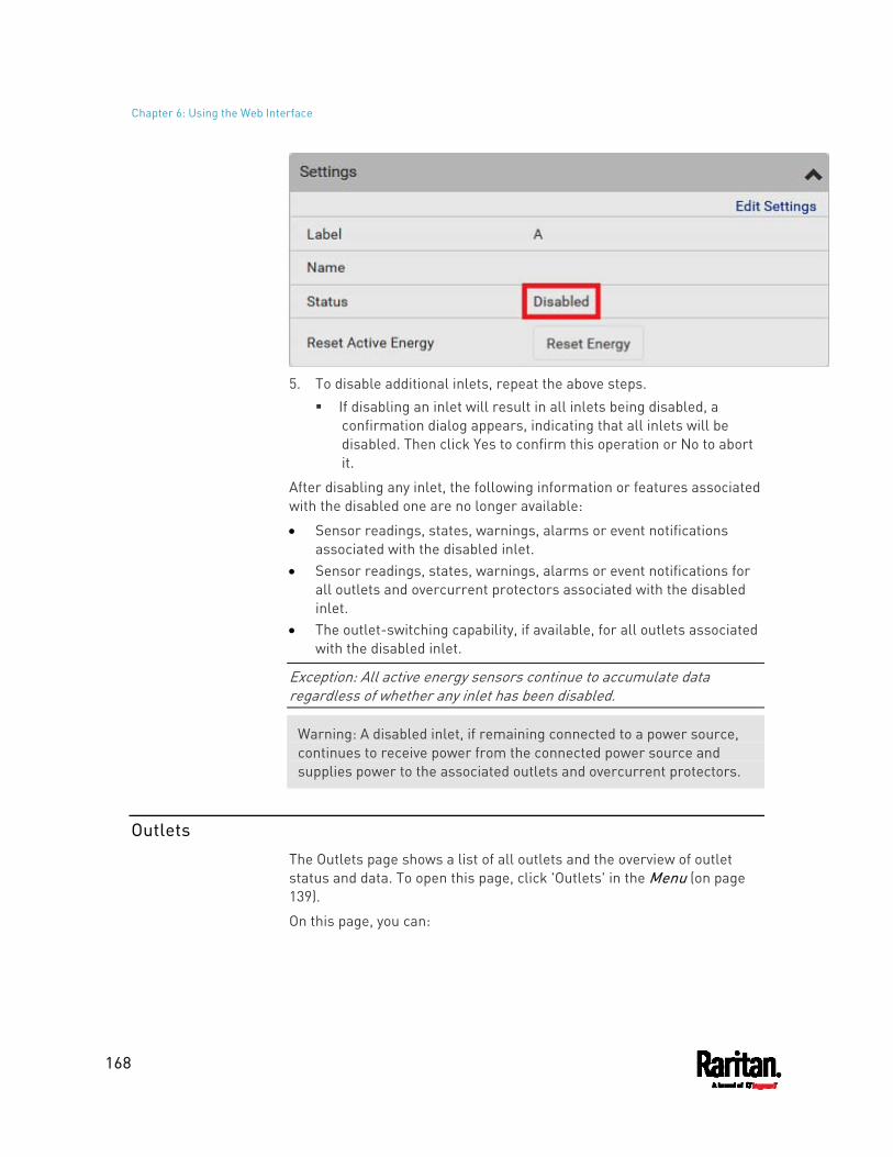
Chapter 6: Using the Web Interface
168
5. To disable additional inlets, repeat the above steps.
If disabling an inlet will result in all inlets being disabled, a confirmation dialog appears, indicating that all inlets will be disabled. Then click Yes to confirm this operation or No to abort it.
After disabling any inlet, the following information or features associated with the disabled one are no longer available:
Sensor readings, states, warnings, alarms or event notifications associated with the disabled inlet.
Sensor readings, states, warnings, alarms or event notifications for all outlets and overcurrent protectors associated with the disabled inlet.
The outlet-switching capability, if available, for all outlets associated with the disabled inlet.
Exception: All active energy sensors continue to accumulate data regardless of whether any inlet has been disabled.
Warning: A disabled inlet, if remaining connected to a power source, continues to receive power from the connected power source and supplies power to the associated outlets and overcurrent protectors.
Outlets
The Outlets page shows a list of all outlets and the overview of outlet status and data. To open this page, click 'Outlets' in the Menu (on page 139).
On this page, you can:
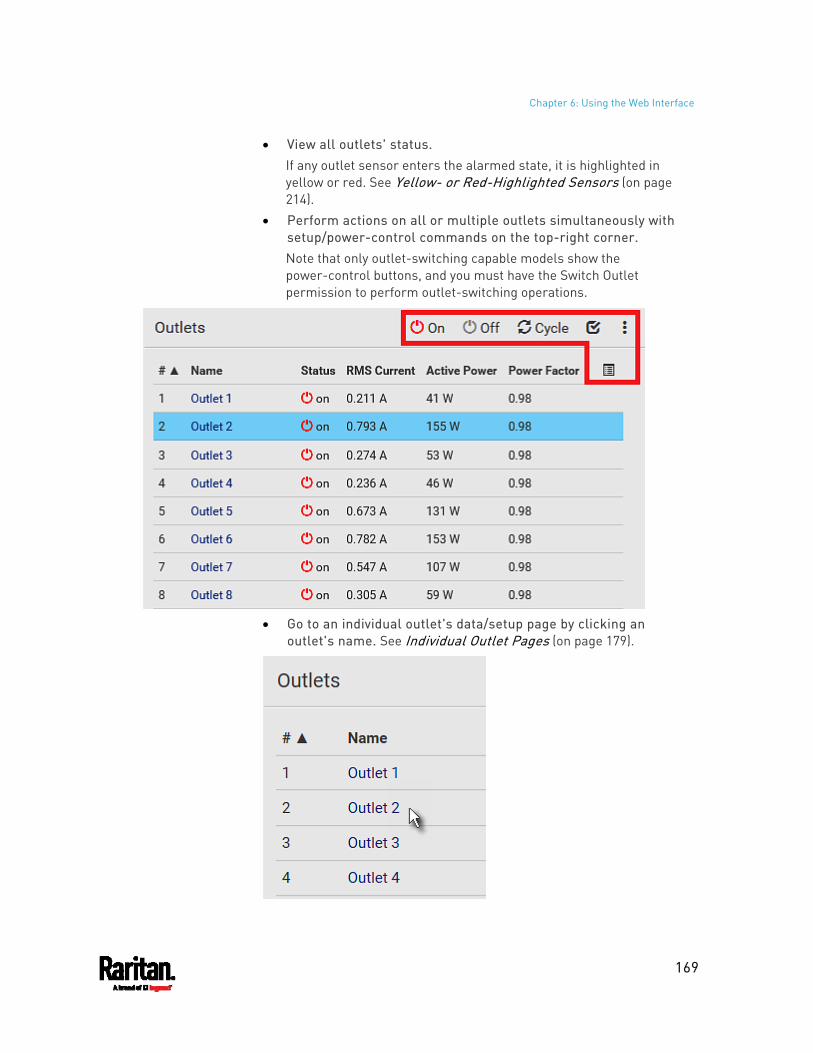
Chapter 6: Using the Web Interface
169
View all outlets' status. If any outlet sensor enters the alarmed state, it is highlighted in yellow or red. See Yellow- or Red-Highlighted Sensors (on page 214).
Perform actions on all or multiple outlets simultaneously with setup/power-control commands on the top-right corner. Note that only outlet-switching capable models show the power-control buttons, and you must have the Switch Outlet permission to perform outlet-switching operations.
Go to an individual outlet's data/setup page by clicking an
outlet's name. See Individual Outlet Pages (on page 179).
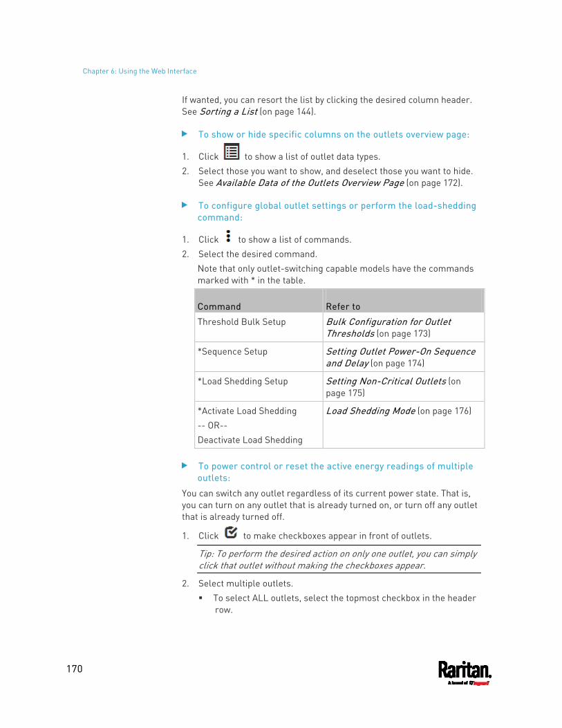
Chapter 6: Using the Web Interface
170
If wanted, you can resort the list by clicking the desired column header. See Sorting a List (on page 144).
To show or hide specific columns on the outlets overview page:
1. Click to show a list of outlet data types. 2. Select those you want to show, and deselect those you want to hide.
See Available Data of the Outlets Overview Page (on page 172).
To configure global outlet settings or perform the load-shedding command:
1. Click to show a list of commands. 2. Select the desired command.
Note that only outlet-switching capable models have the commands marked with * in the table.
Command Refer to
Threshold Bulk Setup Bulk Configuration for Outlet Thresholds (on page 173)
*Sequence Setup Setting Outlet Power-On Sequence and Delay (on page 174)
*Load Shedding Setup Setting Non-Critical Outlets (on page 175)
*Activate Load Shedding -- OR-- Deactivate Load Shedding
Load Shedding Mode (on page 176)
To power control or reset the active energy readings of multiple outlets:
You can switch any outlet regardless of its current power state. That is, you can turn on any outlet that is already turned on, or turn off any outlet that is already turned off.
1. Click to make checkboxes appear in front of outlets.
Tip: To perform the desired action on only one outlet, you can simply click that outlet without making the checkboxes appear.
2. Select multiple outlets. To select ALL outlets, select the topmost checkbox in the header
row.
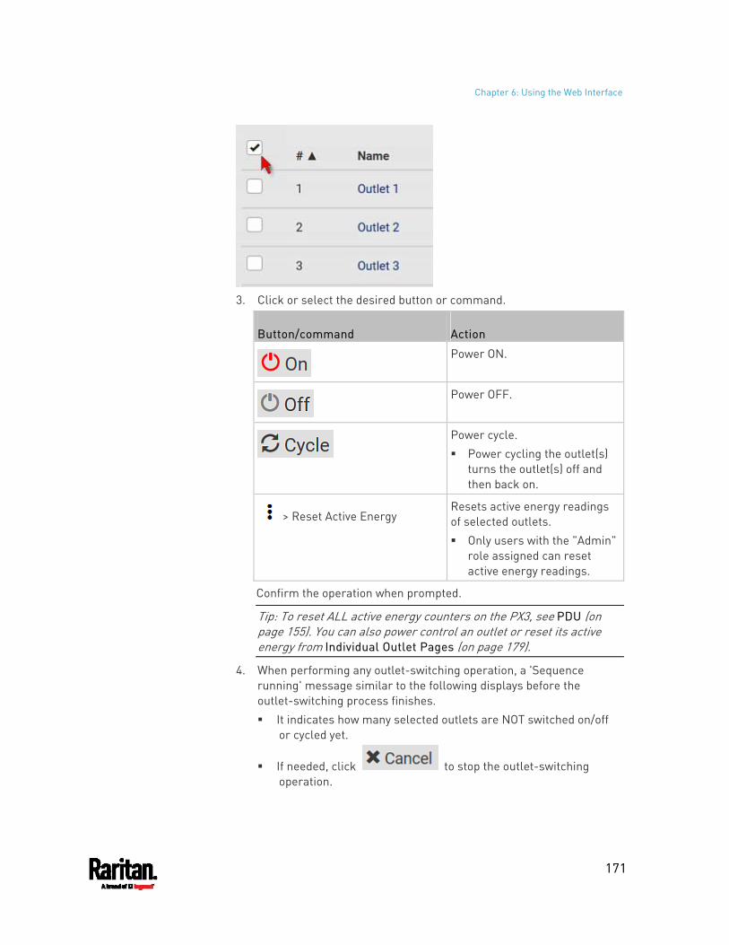
Chapter 6: Using the Web Interface
171
3. Click or select the desired button or command.
Button/command Action
Power ON.
Power OFF.
Power cycle. Power cycling the outlet(s)
turns the outlet(s) off and then back on.
> Reset Active Energy Resets active energy readings of selected outlets. Only users with the "Admin"
role assigned can reset active energy readings.
Confirm the operation when prompted.
Tip: To reset ALL active energy counters on the PX3, see PDU (on page 155). You can also power control an outlet or reset its active energy from Individual Outlet Pages (on page 179).
4. When performing any outlet-switching operation, a 'Sequence running' message similar to the following displays before the outlet-switching process finishes. It indicates how many selected outlets are NOT switched on/off
or cycled yet.
If needed, click to stop the outlet-switching operation.
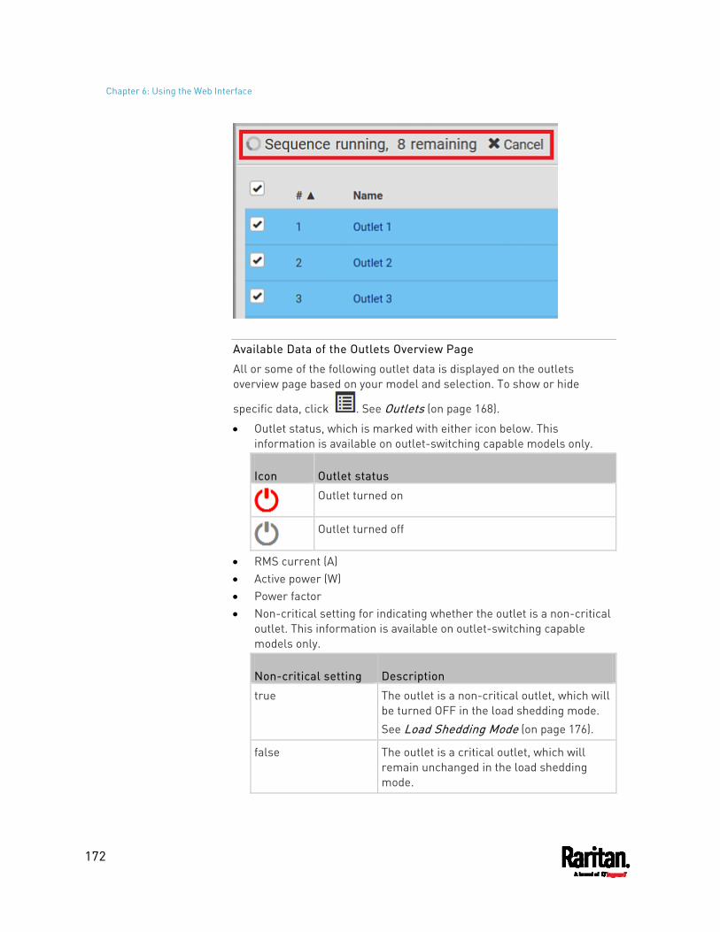
Chapter 6: Using the Web Interface
172
Available Data of the Outlets Overview Page
All or some of the following outlet data is displayed on the outlets overview page based on your model and selection. To show or hide
specific data, click . See Outlets (on page 168).
Outlet status, which is marked with either icon below. This information is available on outlet-switching capable models only.
Icon Outlet status
Outlet turned on
Outlet turned off
RMS current (A) Active power (W) Power factor Non-critical setting for indicating whether the outlet is a non-critical
outlet. This information is available on outlet-switching capable models only.
Non-critical setting Description
true The outlet is a non-critical outlet, which will be turned OFF in the load shedding mode. See Load Shedding Mode (on page 176).
false The outlet is a critical outlet, which will remain unchanged in the load shedding mode.
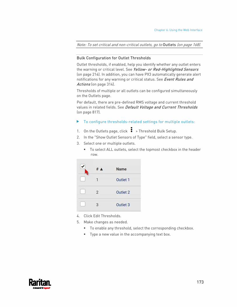
Chapter 6: Using the Web Interface
173
Note: To set critical and non-critical outlets, go to Outlets (on page 168).
Bulk Configuration for Outlet Thresholds
Outlet thresholds, if enabled, help you identify whether any outlet enters the warning or critical level. See Yellow- or Red-Highlighted Sensors (on page 214). In addition, you can have PX3 automatically generate alert notifications for any warning or critical status. See Event Rules and Actions (on page 314).
Thresholds of multiple or all outlets can be configured simultaneously on the Outlets page.
Per default, there are pre-defined RMS voltage and current threshold values in related fields. See Default Voltage and Current Thresholds (on page 817).
To configure thresholds-related settings for multiple outlets:
1. On the Outlets page, click > Threshold Bulk Setup. 2. In the "Show Outlet Sensors of Type" field, select a sensor type. 3. Select one or multiple outlets.
To select ALL outlets, select the topmost checkbox in the header row.
4. Click Edit Thresholds. 5. Make changes as needed.
To enable any threshold, select the corresponding checkbox. Type a new value in the accompanying text box.
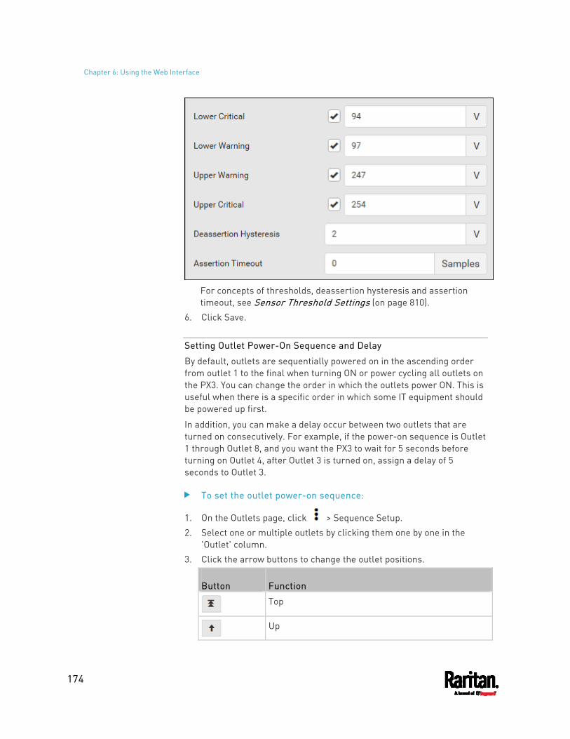
Chapter 6: Using the Web Interface
174
For concepts of thresholds, deassertion hysteresis and assertion timeout, see Sensor Threshold Settings (on page 810).
6. Click Save.
Setting Outlet Power-On Sequence and Delay
By default, outlets are sequentially powered on in the ascending order from outlet 1 to the final when turning ON or power cycling all outlets on the PX3. You can change the order in which the outlets power ON. This is useful when there is a specific order in which some IT equipment should be powered up first.
In addition, you can make a delay occur between two outlets that are turned on consecutively. For example, if the power-on sequence is Outlet 1 through Outlet 8, and you want the PX3 to wait for 5 seconds before turning on Outlet 4, after Outlet 3 is turned on, assign a delay of 5 seconds to Outlet 3.
To set the outlet power-on sequence:
1. On the Outlets page, click > Sequence Setup. 2. Select one or multiple outlets by clicking them one by one in the
'Outlet' column. 3. Click the arrow buttons to change the outlet positions.
Button Function
Top
Up
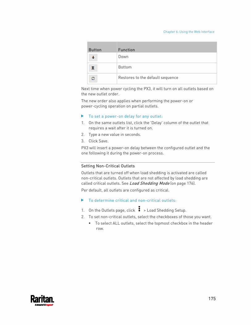
Chapter 6: Using the Web Interface
175
Button Function
Down
Bottom
Restores to the default sequence
Next time when power cycling the PX3, it will turn on all outlets based on the new outlet order.
The new order also applies when performing the power-on or power-cycling operation on partial outlets.
To set a power-on delay for any outlet: 1. On the same outlets list, click the 'Delay' column of the outlet that
requires a wait after it is turned on. 2. Type a new value in seconds. 3. Click Save.
PX3 will insert a power-on delay between the configured outlet and the one following it during the power-on process.
Setting Non-Critical Outlets
Outlets that are turned off when load shedding is activated are called non-critical outlets. Outlets that are not affected by load shedding are called critical outlets. See Load Shedding Mode (on page 176).
Per default, all outlets are configured as critical.
To determine critical and non-critical outlets:
1. On the Outlets page, click > Load Shedding Setup. 2. To set non-critical outlets, select the checkboxes of those you want.
To select ALL outlets, select the topmost checkbox in the header row.
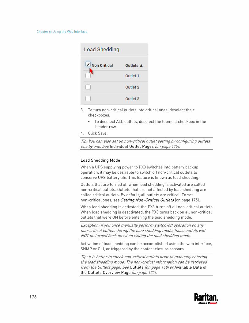
Chapter 6: Using the Web Interface
176
3. To turn non-critical outlets into critical ones, deselect their
checkboxes. To deselect ALL outlets, deselect the topmost checkbox in the
header row. 4. Click Save.
Tip: You can also set up non-critical outlet setting by configuring outlets one by one. See Individual Outlet Pages (on page 179).
Load Shedding Mode
When a UPS supplying power to PX3 switches into battery backup operation, it may be desirable to switch off non-critical outlets to conserve UPS battery life. This feature is known as load shedding.
Outlets that are turned off when load shedding is activated are called non-critical outlets. Outlets that are not affected by load shedding are called critical outlets. By default, all outlets are critical. To set non-critical ones, see Setting Non-Critical Outlets (on page 175).
When load shedding is activated, the PX3 turns off all non-critical outlets. When load shedding is deactivated, the PX3 turns back on all non-critical outlets that were ON before entering the load shedding mode.
Exception: If you once manually perform switch-off operation on any non-critical outlets during the load shedding mode, those outlets will NOT be turned back on when exiting the load shedding mode.
Activation of load shedding can be accomplished using the web interface, SNMP or CLI, or triggered by the contact closure sensors.
Tip: It is better to check non-critical outlets prior to manually entering the load shedding mode. The non-critical information can be retrieved from the Outlets page. See Outlets (on page 168) or Available Data of the Outlets Overview Page (on page 172).
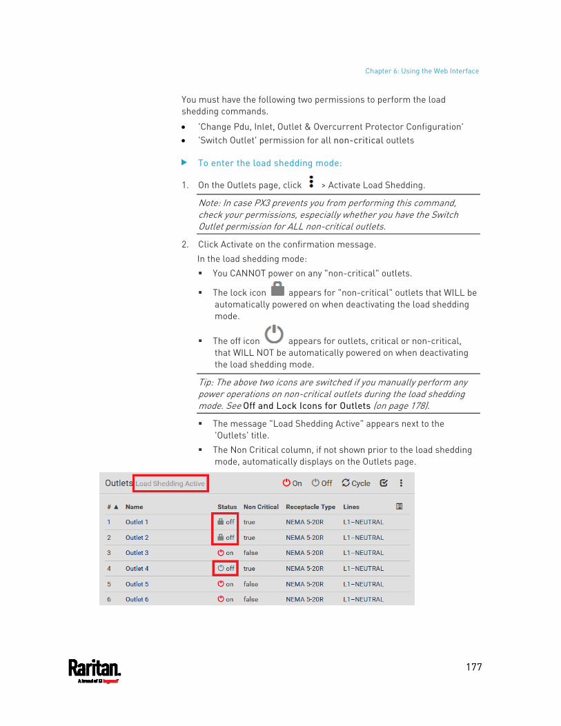
Chapter 6: Using the Web Interface
177
You must have the following two permissions to perform the load shedding commands.
'Change Pdu, Inlet, Outlet & Overcurrent Protector Configuration' 'Switch Outlet' permission for all non-critical outlets
To enter the load shedding mode:
1. On the Outlets page, click > Activate Load Shedding.
Note: In case PX3 prevents you from performing this command, check your permissions, especially whether you have the Switch Outlet permission for ALL non-critical outlets.
2. Click Activate on the confirmation message. In the load shedding mode: You CANNOT power on any "non-critical" outlets.
The lock icon appears for "non-critical" outlets that WILL be automatically powered on when deactivating the load shedding mode.
The off icon appears for outlets, critical or non-critical, that WILL NOT be automatically powered on when deactivating the load shedding mode.
Tip: The above two icons are switched if you manually perform any power operations on non-critical outlets during the load shedding mode. See Off and Lock Icons for Outlets (on page 178).
The message "Load Shedding Active" appears next to the 'Outlets' title.
The Non Critical column, if not shown prior to the load shedding mode, automatically displays on the Outlets page.
Chapter 6: Using the Web Interface
178
Tip: To make the Non Critical column appear when the load shedding mode is not activated yet. See Outlets (on page 168) or Available Data of the Outlets Overview Page (on page 172).
To exit from the load shedding mode:
1. On the Outlets page, click > Deactivate Load Shedding. 2. Click Deactivate on the confirmation message.
Now you can turn on/off any outlets.
TIP -- automatic load shedding via contact closure sensors:
If you have connected a Raritan contact closure sensor to PX3, you can set up an event rule in a manner that this sensor's status change automatically activates or deactivates the load shedding mode. For an example, see Sample Environmental-Sensor-Level Event Rule (on page 372).
Off and Lock Icons for Outlets
This section further explains the following two icons for outlets, which display in the load shedding mode.
Lock icon : It means the outlet WILL be automatically powered on after deactivating the load shedding mode.
Off icon : It means the outlet WILL NOT be automatically powered on when deactivating the load shedding mode.
Which outlets show the lock icon : Non-critical outlets that were powered ON prior to the load shedding
mode Non-critical outlets that you manually switch on during the load
shedding mode
Note: The switching-on operation does not power on the selected non-critical outlets while the load shedding mode is active, but will cause those outlets to be automatically turn on after disabling the load shedding mode.
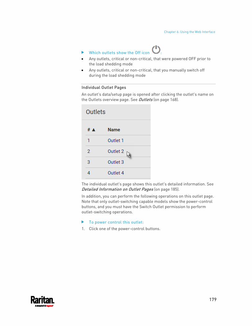
Chapter 6: Using the Web Interface
179
Which outlets show the Off icon : Any outlets, critical or non-critical, that were powered OFF prior to
the load shedding mode Any outlets, critical or non-critical, that you manually switch off
during the load shedding mode
Individual Outlet Pages
An outlet's data/setup page is opened after clicking the outlet's name on the Outlets overview page. See Outlets (on page 168).
The individual outlet's page shows this outlet's detailed information. See Detailed Information on Outlet Pages (on page 185).
In addition, you can perform the following operations on this outlet page. Note that only outlet-switching capable models show the power-control buttons, and you must have the Switch Outlet permission to perform outlet-switching operations.
To power control this outlet: 1. Click one of the power-control buttons.
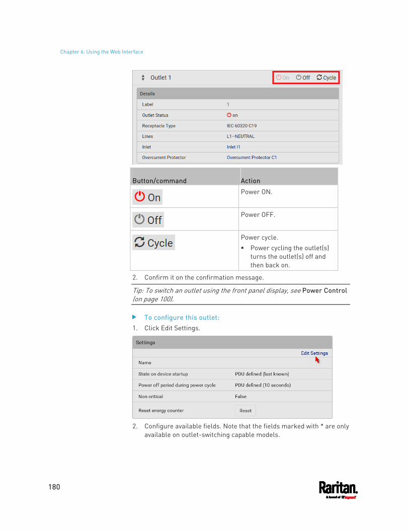
Chapter 6: Using the Web Interface
180
Button/command Action
Power ON.
Power OFF.
Power cycle. Power cycling the outlet(s)
turns the outlet(s) off and then back on.
2. Confirm it on the confirmation message.
Tip: To switch an outlet using the front panel display, see Power Control (on page 100).
To configure this outlet: 1. Click Edit Settings.
2. Configure available fields. Note that the fields marked with * are only
available on outlet-switching capable models.
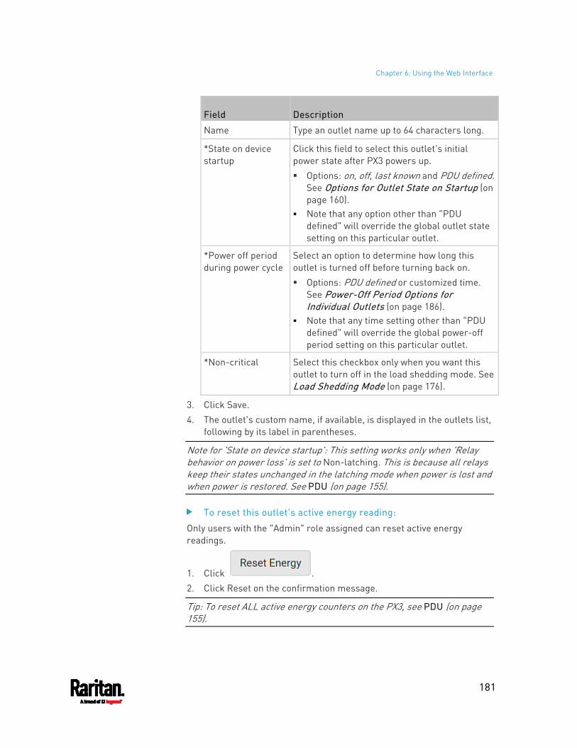
Chapter 6: Using the Web Interface
181
Field Description
Name Type an outlet name up to 64 characters long.
*State on device startup
Click this field to select this outlet's initial power state after PX3 powers up. Options: on, off, last known and PDU defined.
See Options for Outlet State on Startup (on page 160).
Note that any option other than "PDU defined" will override the global outlet state setting on this particular outlet.
*Power off period during power cycle
Select an option to determine how long this outlet is turned off before turning back on. Options: PDU defined or customized time.
See Power-Off Period Options for Individual Outlets (on page 186).
Note that any time setting other than "PDU defined" will override the global power-off period setting on this particular outlet.
*Non-critical Select this checkbox only when you want this outlet to turn off in the load shedding mode. See Load Shedding Mode (on page 176).
3. Click Save. 4. The outlet's custom name, if available, is displayed in the outlets list,
following by its label in parentheses.
Note for 'State on device startup': This setting works only when 'Relay behavior on power loss' is set to Non-latching. This is because all relays keep their states unchanged in the latching mode when power is lost and when power is restored. See PDU (on page 155).
To reset this outlet's active energy reading:
Only users with the "Admin" role assigned can reset active energy readings.
1. Click . 2. Click Reset on the confirmation message.
Tip: To reset ALL active energy counters on the PX3, see PDU (on page 155).
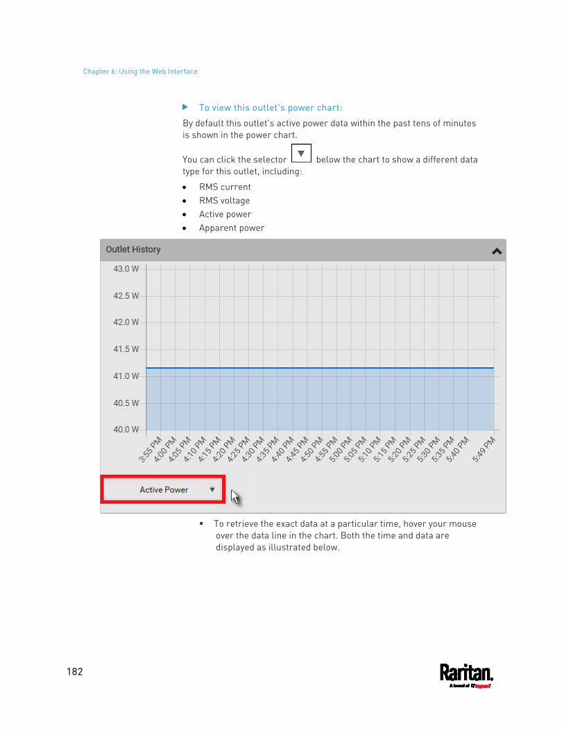
Chapter 6: Using the Web Interface
182
To view this outlet's power chart:
By default this outlet's active power data within the past tens of minutes is shown in the power chart.
You can click the selector below the chart to show a different data type for this outlet, including:
RMS current RMS voltage Active power Apparent power
To retrieve the exact data at a particular time, hover your mouse
over the data line in the chart. Both the time and data are displayed as illustrated below.
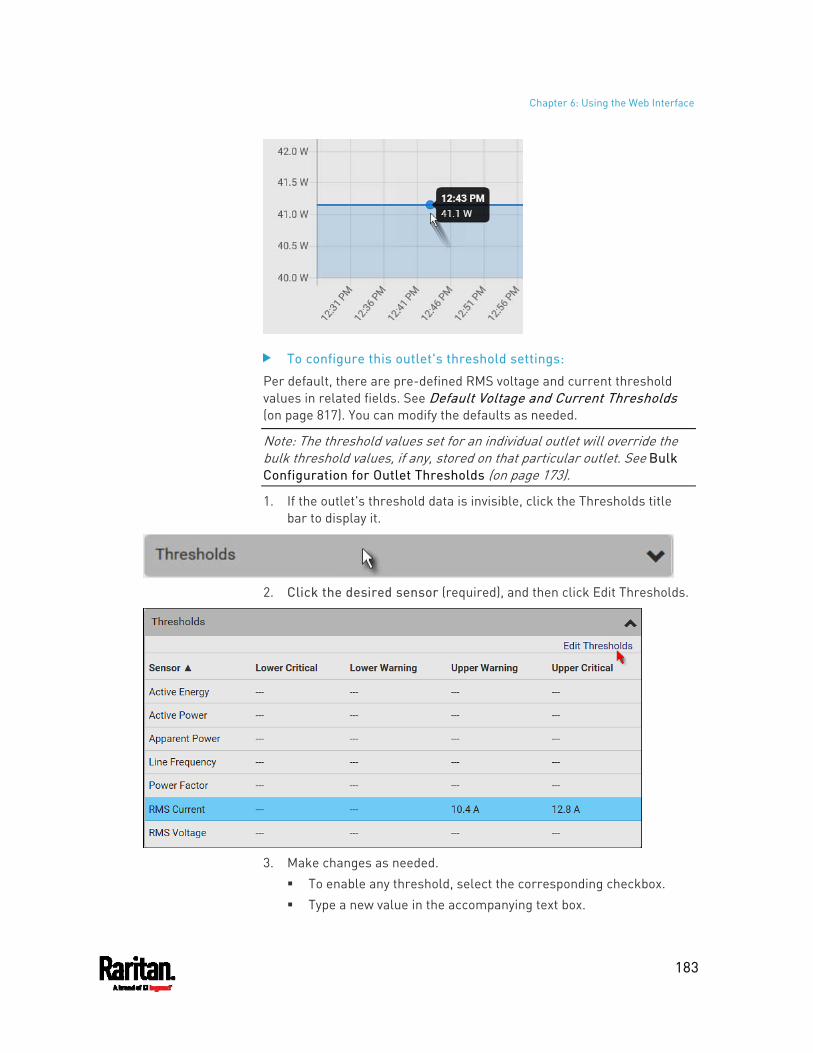
Chapter 6: Using the Web Interface
183
To configure this outlet's threshold settings:
Per default, there are pre-defined RMS voltage and current threshold values in related fields. See Default Voltage and Current Thresholds (on page 817). You can modify the defaults as needed.
Note: The threshold values set for an individual outlet will override the bulk threshold values, if any, stored on that particular outlet. See Bulk Configuration for Outlet Thresholds (on page 173).
1. If the outlet's threshold data is invisible, click the Thresholds title bar to display it.
2. Click the desired sensor (required), and then click Edit Thresholds.
3. Make changes as needed.
To enable any threshold, select the corresponding checkbox. Type a new value in the accompanying text box.
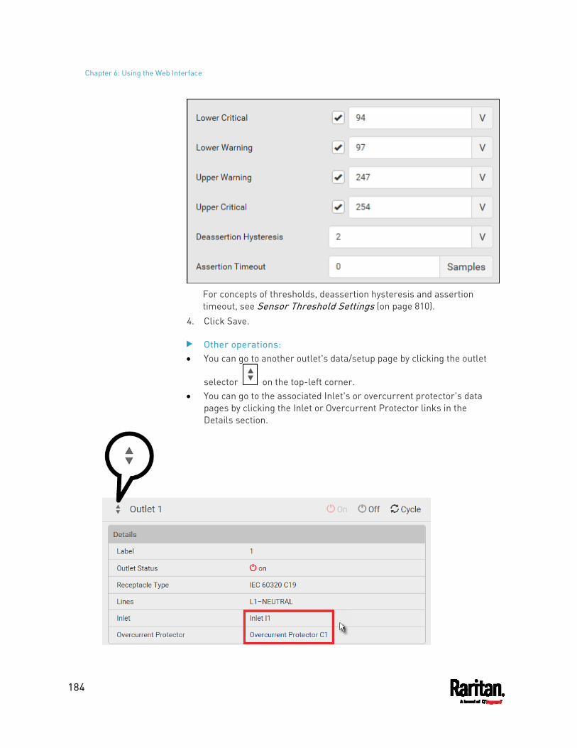
Chapter 6: Using the Web Interface
184
For concepts of thresholds, deassertion hysteresis and assertion timeout, see Sensor Threshold Settings (on page 810).
4. Click Save.
Other operations: You can go to another outlet's data/setup page by clicking the outlet
selector on the top-left corner. You can go to the associated Inlet's or overcurrent protector's data
pages by clicking the Inlet or Overcurrent Protector links in the Details section.
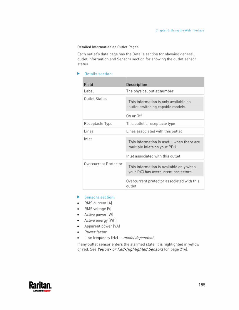
Chapter 6: Using the Web Interface
185
Detailed Information on Outlet Pages
Each outlet's data page has the Details section for showing general outlet information and Sensors section for showing the outlet sensor status.
Details section:
Field Description
Label The physical outlet number
Outlet Status This information is only available on outlet-switching capable models.
On or Off
Receptacle Type This outlet's receptacle type
Lines Lines associated with this outlet
Inlet This information is useful when there are multiple inlets on your PDU.
Inlet associated with this outlet
Overcurrent ProtectorThis information is available only when your PX3 has overcurrent protectors.
Overcurrent protector associated with this outlet
Sensors section: RMS current (A) RMS voltage (V) Active power (W) Active energy (Wh) Apparent power (VA) Power factor Line frequency (Hz) -- model dependent If any outlet sensor enters the alarmed state, it is highlighted in yellow or red. See Yellow- or Red-Highlighted Sensors (on page 214).
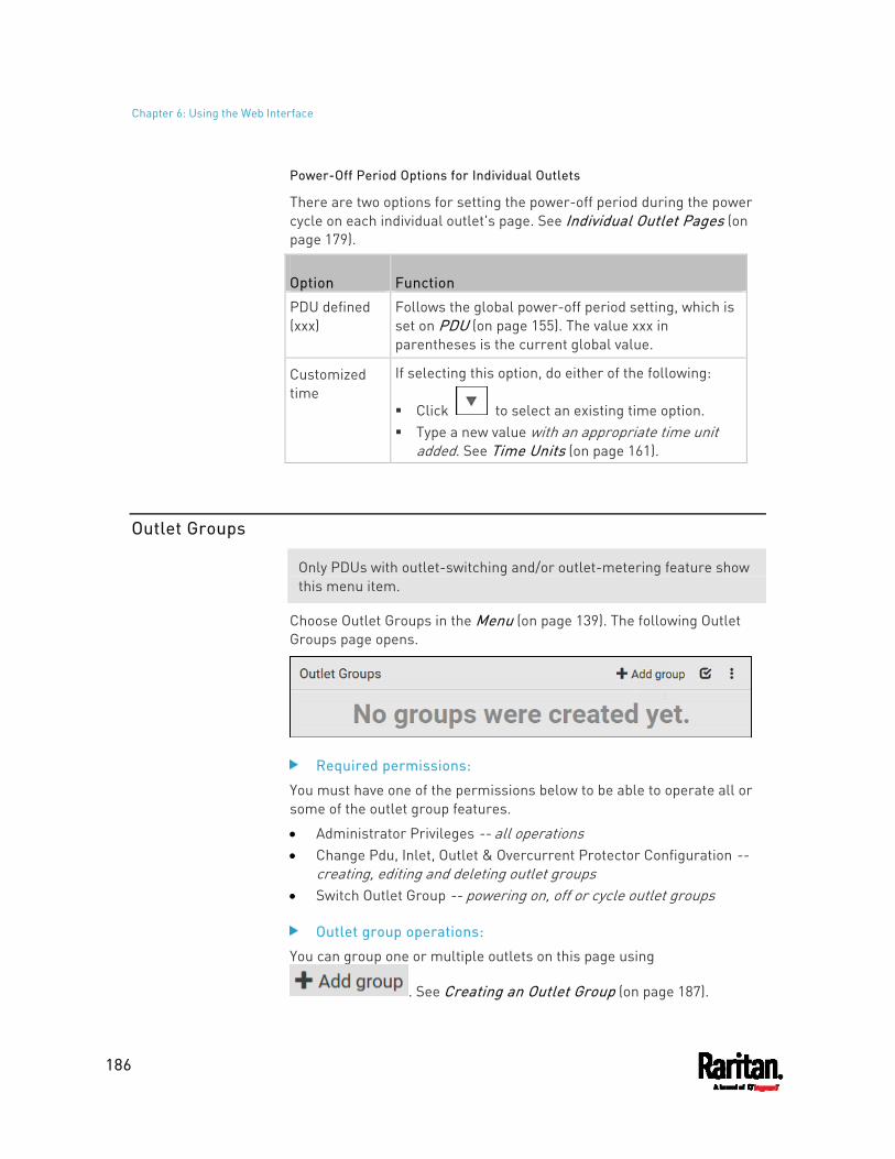
Chapter 6: Using the Web Interface
186
Power-Off Period Options for Individual Outlets
There are two options for setting the power-off period during the power cycle on each individual outlet's page. See Individual Outlet Pages (on page 179).
Option Function
PDU defined (xxx)
Follows the global power-off period setting, which is set on PDU (on page 155). The value xxx in parentheses is the current global value.
Customized time
If selecting this option, do either of the following:
Click to select an existing time option. Type a new value with an appropriate time unit
added. See Time Units (on page 161).
Outlet Groups
Only PDUs with outlet-switching and/or outlet-metering feature show this menu item.
Choose Outlet Groups in the Menu (on page 139). The following Outlet Groups page opens.
Required permissions:
You must have one of the permissions below to be able to operate all or some of the outlet group features.
Administrator Privileges -- all operations Change Pdu, Inlet, Outlet & Overcurrent Protector Configuration --
creating, editing and deleting outlet groups Switch Outlet Group -- powering on, off or cycle outlet groups
Outlet group operations:
You can group one or multiple outlets on this page using
. See Creating an Outlet Group (on page 187).
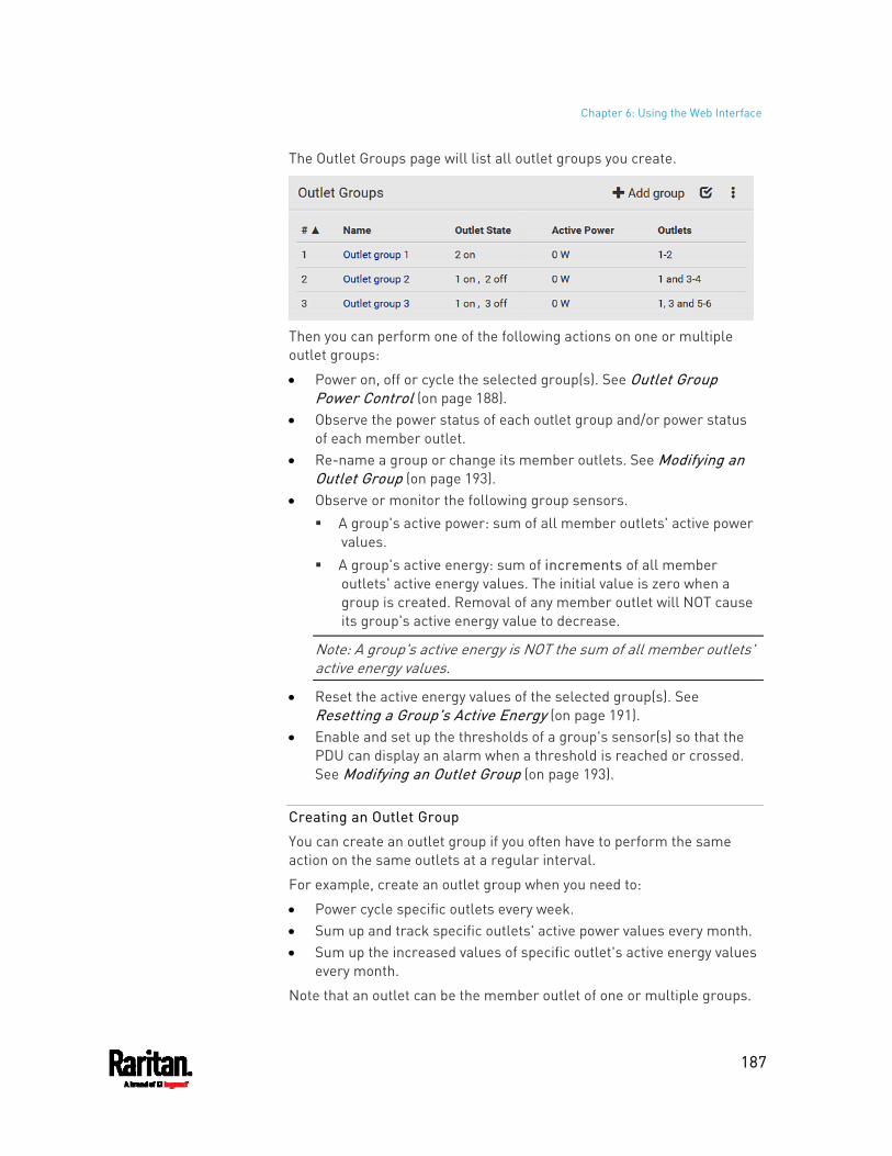
Chapter 6: Using the Web Interface
187
The Outlet Groups page will list all outlet groups you create.
Then you can perform one of the following actions on one or multiple outlet groups:
Power on, off or cycle the selected group(s). See Outlet Group Power Control (on page 188).
Observe the power status of each outlet group and/or power status of each member outlet.
Re-name a group or change its member outlets. See Modifying an Outlet Group (on page 193).
Observe or monitor the following group sensors. A group's active power: sum of all member outlets' active power
values. A group's active energy: sum of increments of all member
outlets' active energy values. The initial value is zero when a group is created. Removal of any member outlet will NOT cause its group's active energy value to decrease.
Note: A group's active energy is NOT the sum of all member outlets' active energy values.
Reset the active energy values of the selected group(s). See Resetting a Group's Active Energy (on page 191).
Enable and set up the thresholds of a group's sensor(s) so that the PDU can display an alarm when a threshold is reached or crossed. See Modifying an Outlet Group (on page 193).
Creating an Outlet Group
You can create an outlet group if you often have to perform the same action on the same outlets at a regular interval.
For example, create an outlet group when you need to:
Power cycle specific outlets every week. Sum up and track specific outlets' active power values every month. Sum up the increased values of specific outlet's active energy values
every month.
Note that an outlet can be the member outlet of one or multiple groups.
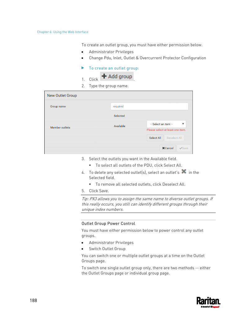
Chapter 6: Using the Web Interface
188
To create an outlet group, you must have either permission below.
Administrator Privileges Change Pdu, Inlet, Outlet & Overcurrent Protector Configuration
To create an outlet group:
1. Click . 2. Type the group name.
3. Select the outlets you want in the Available field.
To select all outlets of the PDU, click Select All.
4. To delete any selected outlet(s), select an outlet's in the Selected field. To remove all selected outlets, click Deselect All.
5. Click Save.
Tip: PX3 allows you to assign the same name to diverse outlet groups. If this really occurs, you still can identify different groups through their unique index numbers.
Outlet Group Power Control
You must have either permission below to power control any outlet groups.
Administrator Privileges Switch Outlet Group
You can switch one or multiple outlet groups at a time on the Outlet Groups page.
To switch one single outlet group only, there are two methods -- either the Outlet Groups page or individual group page.
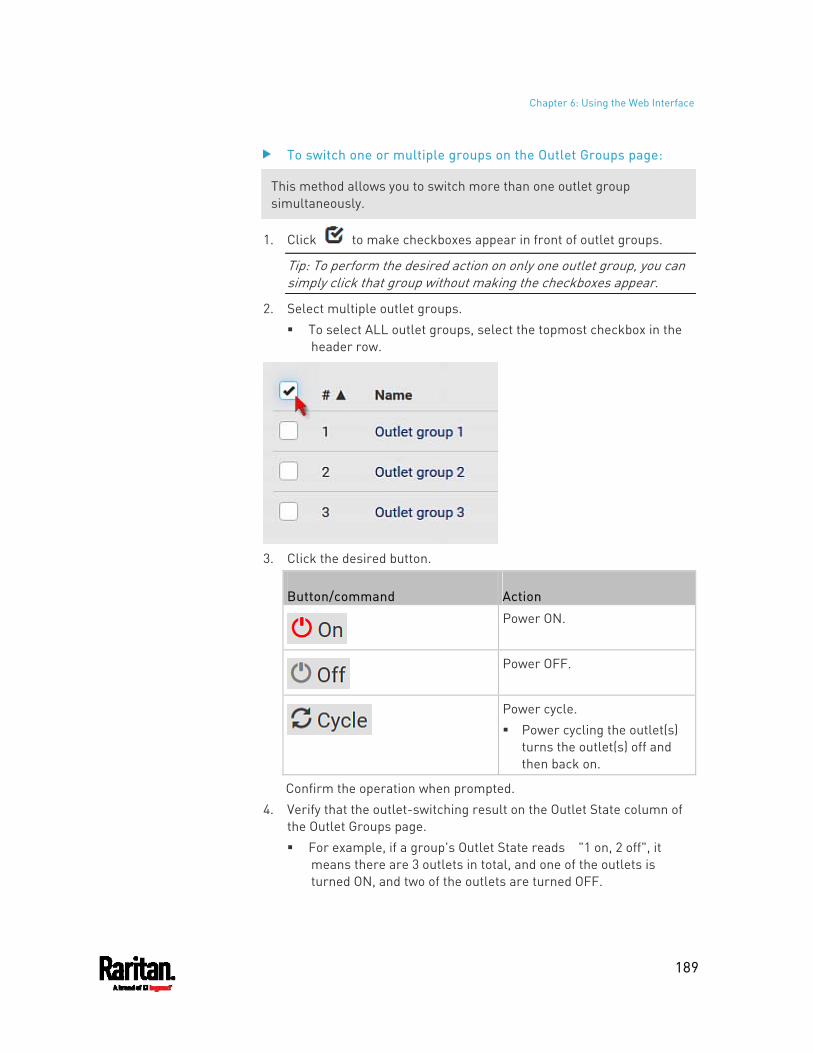
Chapter 6: Using the Web Interface
189
To switch one or multiple groups on the Outlet Groups page:
This method allows you to switch more than one outlet group simultaneously.
1. Click to make checkboxes appear in front of outlet groups.
Tip: To perform the desired action on only one outlet group, you can simply click that group without making the checkboxes appear.
2. Select multiple outlet groups. To select ALL outlet groups, select the topmost checkbox in the
header row.
3. Click the desired button.
Button/command Action
Power ON.
Power OFF.
Power cycle. Power cycling the outlet(s)
turns the outlet(s) off and then back on.
Confirm the operation when prompted. 4. Verify that the outlet-switching result on the Outlet State column of
the Outlet Groups page. For example, if a group's Outlet State reads "1 on, 2 off", it
means there are 3 outlets in total, and one of the outlets is turned ON, and two of the outlets are turned OFF.
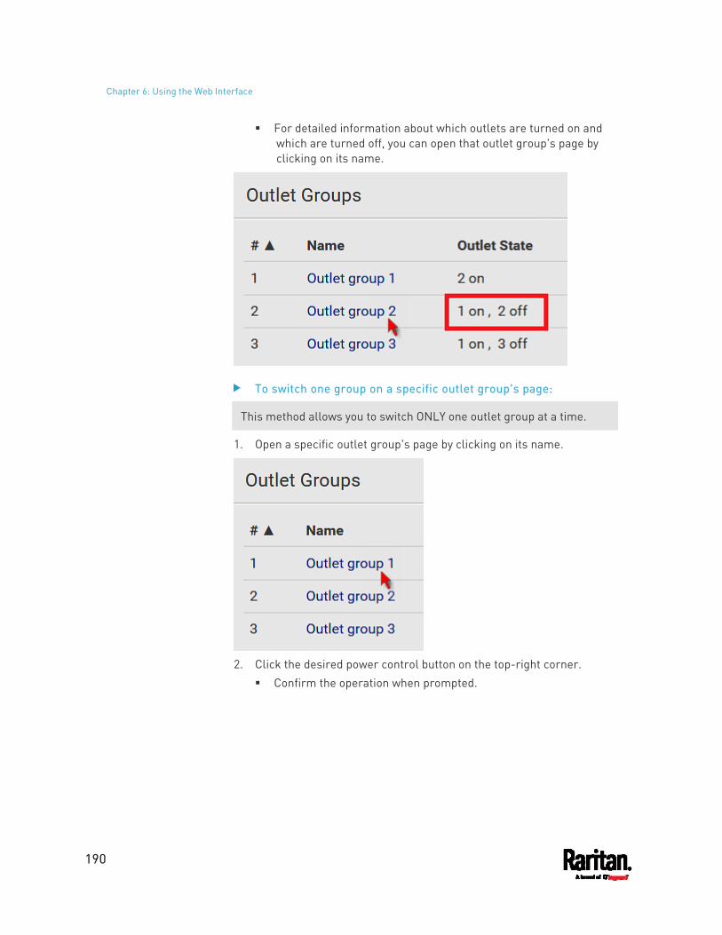
Chapter 6: Using the Web Interface
190
For detailed information about which outlets are turned on and which are turned off, you can open that outlet group's page by clicking on its name.
To switch one group on a specific outlet group's page:
This method allows you to switch ONLY one outlet group at a time.
1. Open a specific outlet group's page by clicking on its name.
2. Click the desired power control button on the top-right corner.
Confirm the operation when prompted.
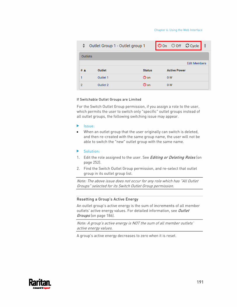
Chapter 6: Using the Web Interface
191
If Switchable Outlet Groups are Limited
For the Switch Outlet Group permission, if you assign a role to the user, which permits the user to switch only "specific" outlet groups instead of all outlet groups, the following switching issue may appear.
Issue: When an outlet group that the user originally can switch is deleted,
and then re-created with the same group name, the user will not be able to switch the "new" outlet group with the same name.
Solution: 1. Edit the role assigned to the user. See Editing or Deleting Roles (on
page 252). 2. Find the Switch Outlet Group permission, and re-select that outlet
group in its outlet group list.
Note: The above issue does not occur for any role which has "All Outlet Groups" selected for its Switch Outlet Group permission.
Resetting a Group's Active Energy
An outlet group's active energy is the sum of increments of all member outlets' active energy values. For detailed information, see Outlet Groups (on page 186).
Note: A group's active energy is NOT the sum of all member outlets' active energy values.
A group's active energy decreases to zero when it is reset.
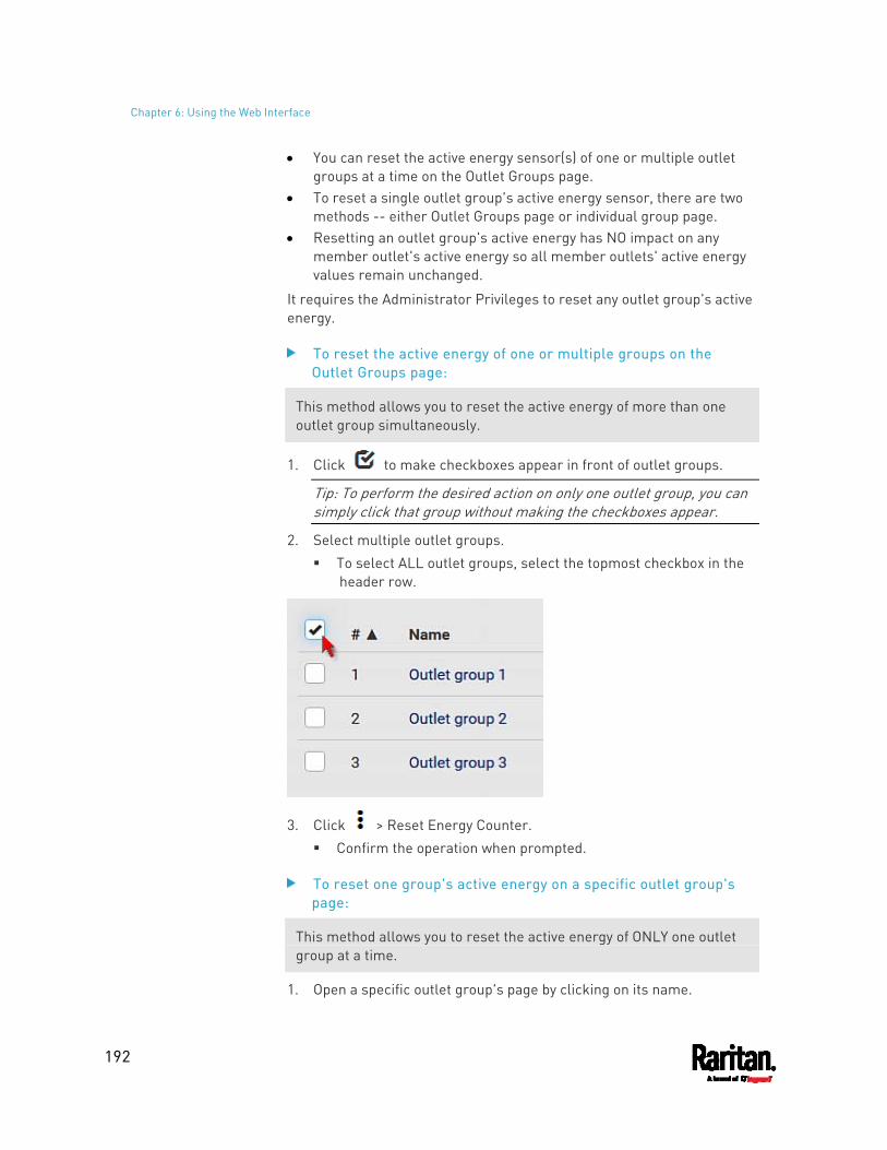
Chapter 6: Using the Web Interface
192
You can reset the active energy sensor(s) of one or multiple outlet groups at a time on the Outlet Groups page.
To reset a single outlet group's active energy sensor, there are two methods -- either Outlet Groups page or individual group page.
Resetting an outlet group's active energy has NO impact on any member outlet's active energy so all member outlets' active energy values remain unchanged.
It requires the Administrator Privileges to reset any outlet group's active energy.
To reset the active energy of one or multiple groups on the Outlet Groups page:
This method allows you to reset the active energy of more than one outlet group simultaneously.
1. Click to make checkboxes appear in front of outlet groups.
Tip: To perform the desired action on only one outlet group, you can simply click that group without making the checkboxes appear.
2. Select multiple outlet groups. To select ALL outlet groups, select the topmost checkbox in the
header row.
3. Click > Reset Energy Counter. Confirm the operation when prompted.
To reset one group's active energy on a specific outlet group's page:
This method allows you to reset the active energy of ONLY one outlet group at a time.
1. Open a specific outlet group's page by clicking on its name.
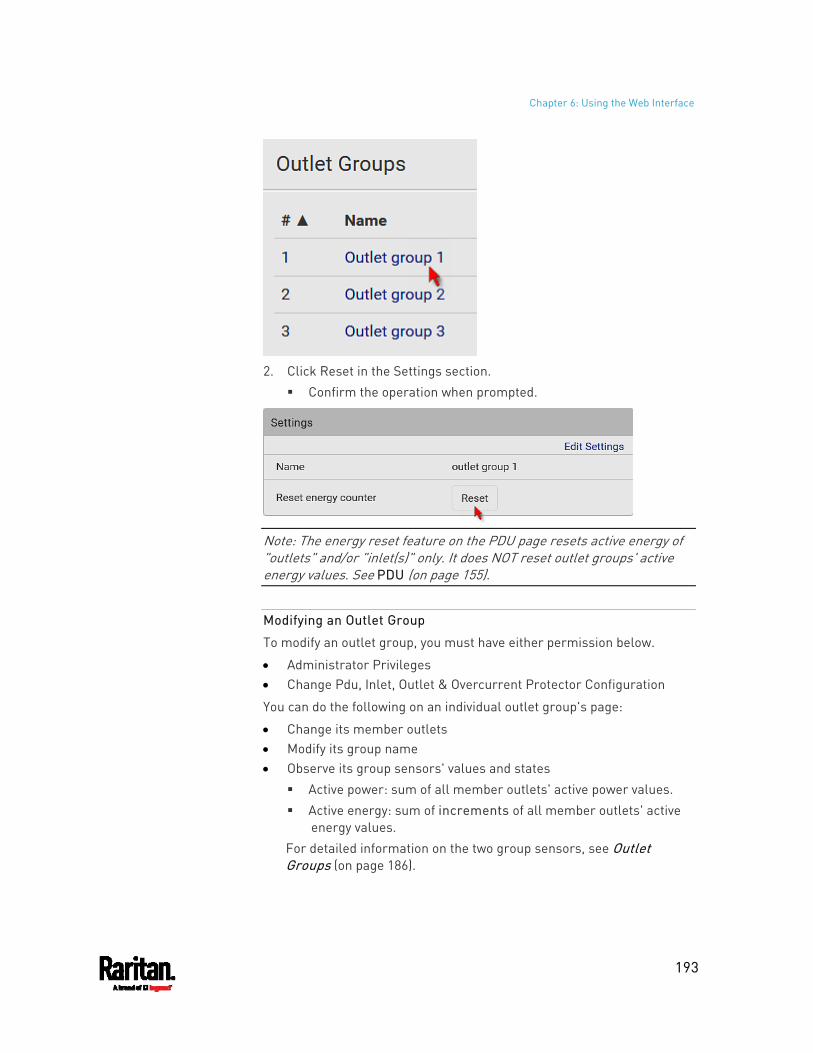
Chapter 6: Using the Web Interface
193
2. Click Reset in the Settings section.
Confirm the operation when prompted.
Note: The energy reset feature on the PDU page resets active energy of "outlets" and/or "inlet(s)" only. It does NOT reset outlet groups' active energy values. See PDU (on page 155).
Modifying an Outlet Group
To modify an outlet group, you must have either permission below.
Administrator Privileges Change Pdu, Inlet, Outlet & Overcurrent Protector Configuration
You can do the following on an individual outlet group's page:
Change its member outlets Modify its group name Observe its group sensors' values and states
Active power: sum of all member outlets' active power values. Active energy: sum of increments of all member outlets' active
energy values. For detailed information on the two group sensors, see Outlet Groups (on page 186).
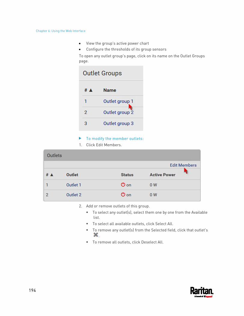
Chapter 6: Using the Web Interface
194
View the group's active power chart Configure the thresholds of its group sensors
To open any outlet group's page, click on its name on the Outlet Groups page.
To modify the member outlets: 1. Click Edit Members.
2. Add or remove outlets of this group.
To select any outlet(s), select them one by one from the Available list.
To select all available outlets, click Select All. To remove any outlet(s) from the Selected field, click that outlet's
. To remove all outlets, click Deselect All.
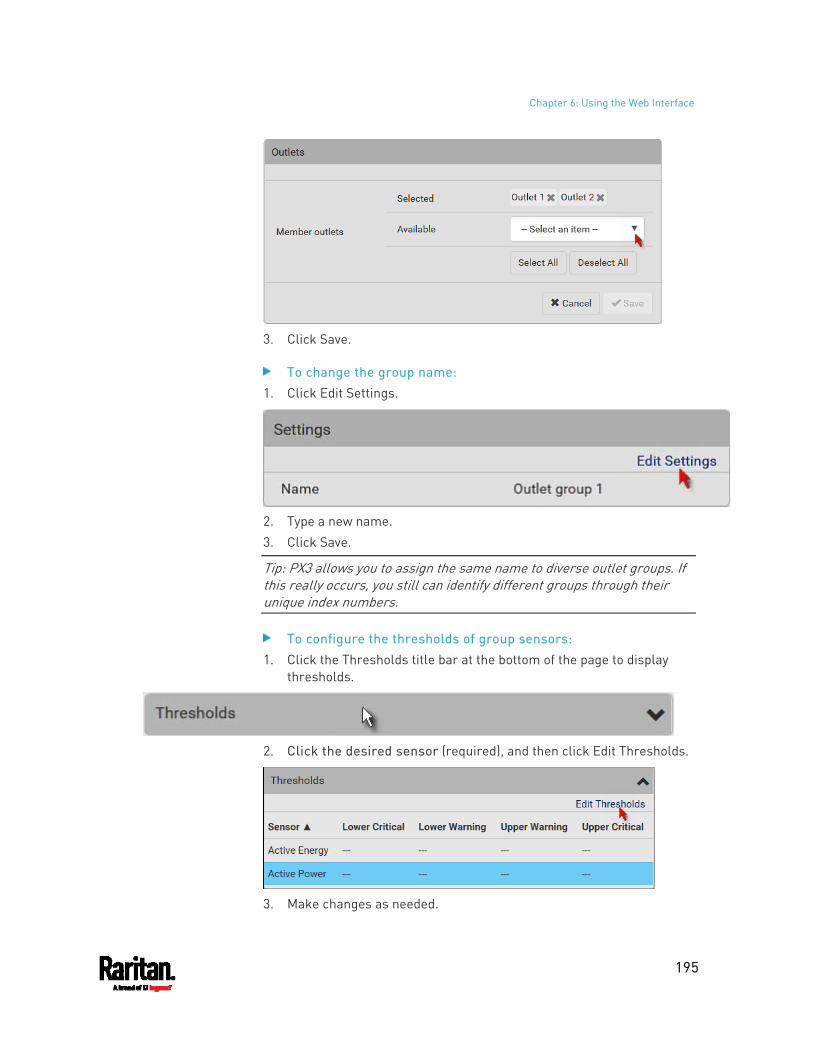
Chapter 6: Using the Web Interface
195
3. Click Save.
To change the group name: 1. Click Edit Settings.
2. Type a new name. 3. Click Save.
Tip: PX3 allows you to assign the same name to diverse outlet groups. If this really occurs, you still can identify different groups through their unique index numbers.
To configure the thresholds of group sensors: 1. Click the Thresholds title bar at the bottom of the page to display
thresholds.
2. Click the desired sensor (required), and then click Edit Thresholds.
3. Make changes as needed.
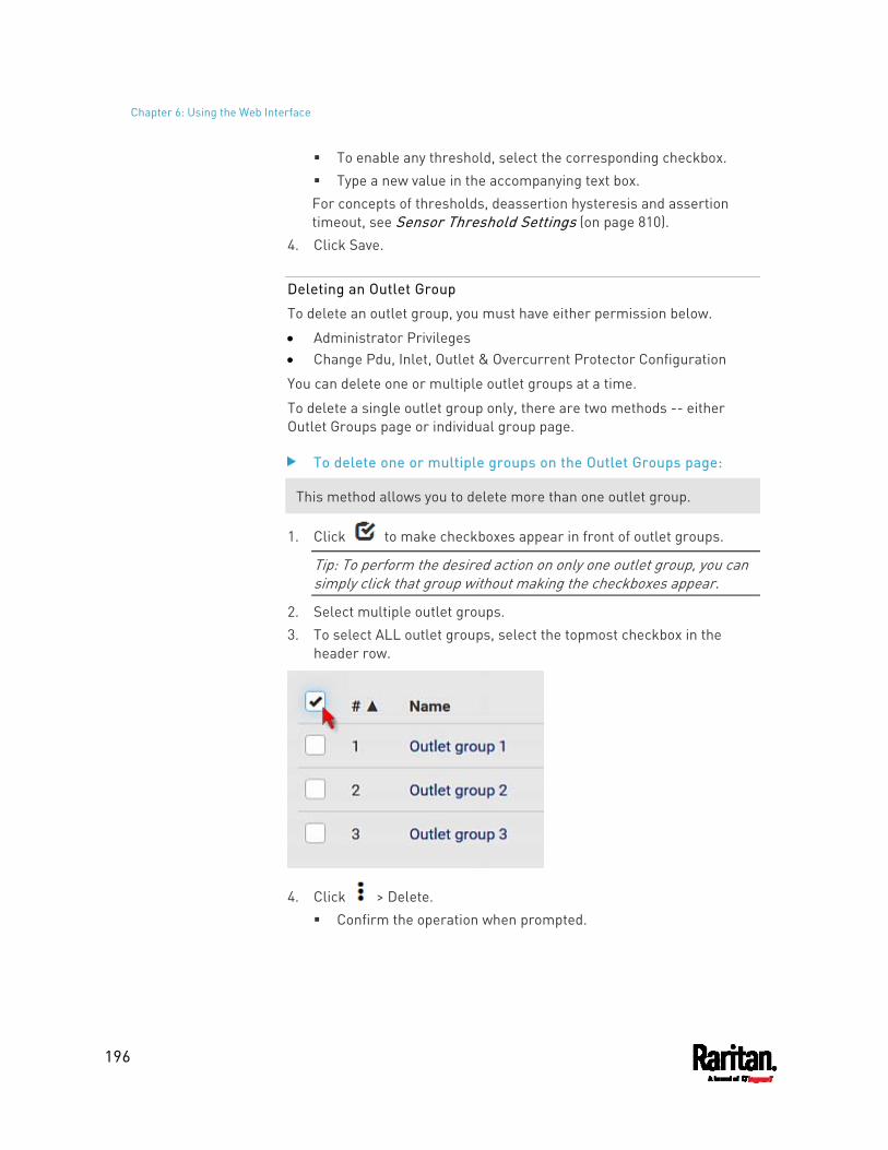
Chapter 6: Using the Web Interface
196
To enable any threshold, select the corresponding checkbox. Type a new value in the accompanying text box. For concepts of thresholds, deassertion hysteresis and assertion timeout, see Sensor Threshold Settings (on page 810).
4. Click Save.
Deleting an Outlet Group
To delete an outlet group, you must have either permission below.
Administrator Privileges Change Pdu, Inlet, Outlet & Overcurrent Protector Configuration
You can delete one or multiple outlet groups at a time.
To delete a single outlet group only, there are two methods -- either Outlet Groups page or individual group page.
To delete one or multiple groups on the Outlet Groups page:
This method allows you to delete more than one outlet group.
1. Click to make checkboxes appear in front of outlet groups.
Tip: To perform the desired action on only one outlet group, you can simply click that group without making the checkboxes appear.
2. Select multiple outlet groups. 3. To select ALL outlet groups, select the topmost checkbox in the
header row.
4. Click > Delete. Confirm the operation when prompted.
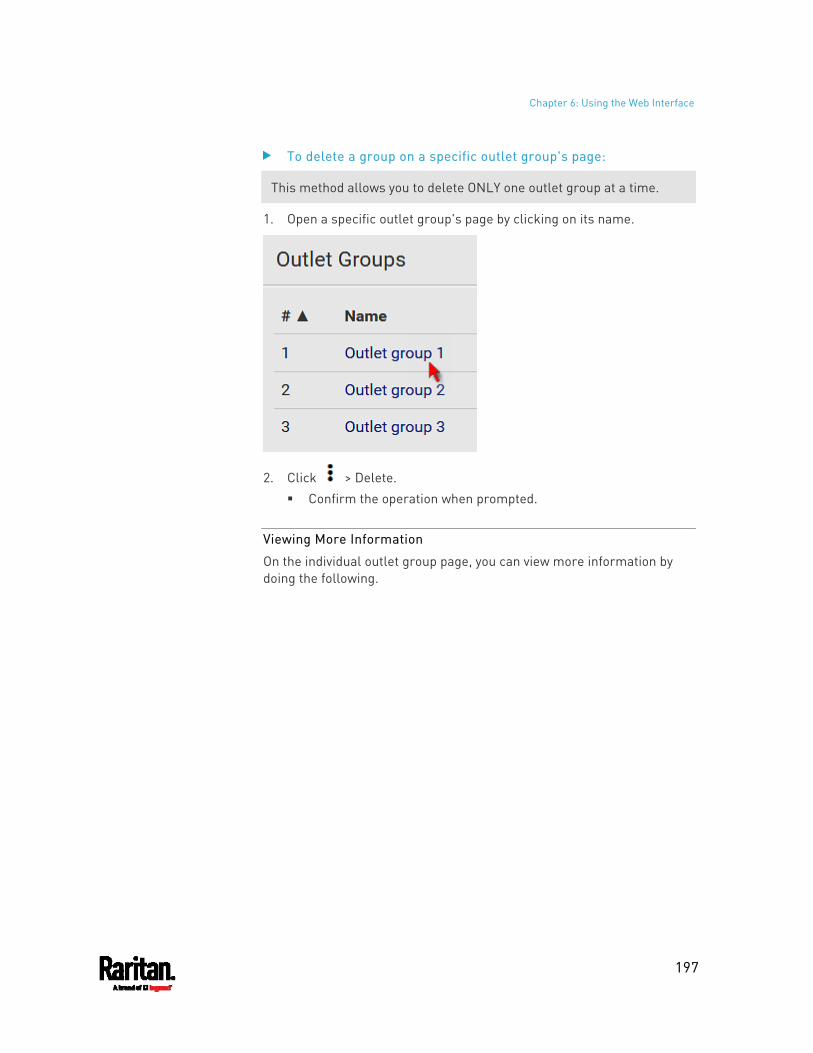
Chapter 6: Using the Web Interface
197
To delete a group on a specific outlet group's page:
This method allows you to delete ONLY one outlet group at a time.
1. Open a specific outlet group's page by clicking on its name.
2. Click > Delete. Confirm the operation when prompted.
Viewing More Information
On the individual outlet group page, you can view more information by doing the following.
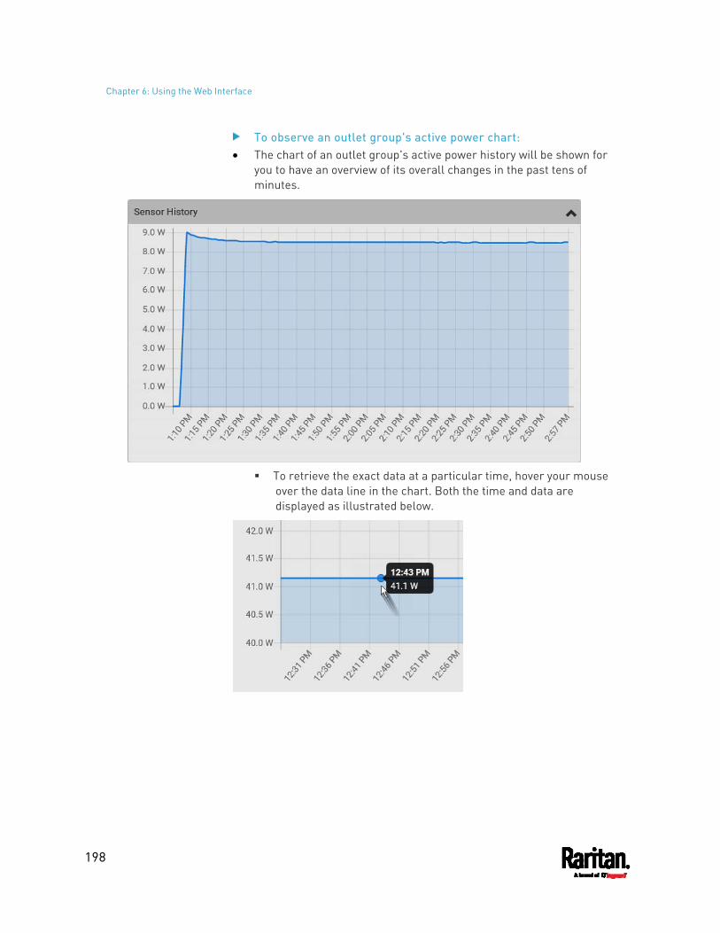
Chapter 6: Using the Web Interface
198
To observe an outlet group's active power chart: The chart of an outlet group's active power history will be shown for
you to have an overview of its overall changes in the past tens of minutes.
To retrieve the exact data at a particular time, hover your mouse
over the data line in the chart. Both the time and data are displayed as illustrated below.
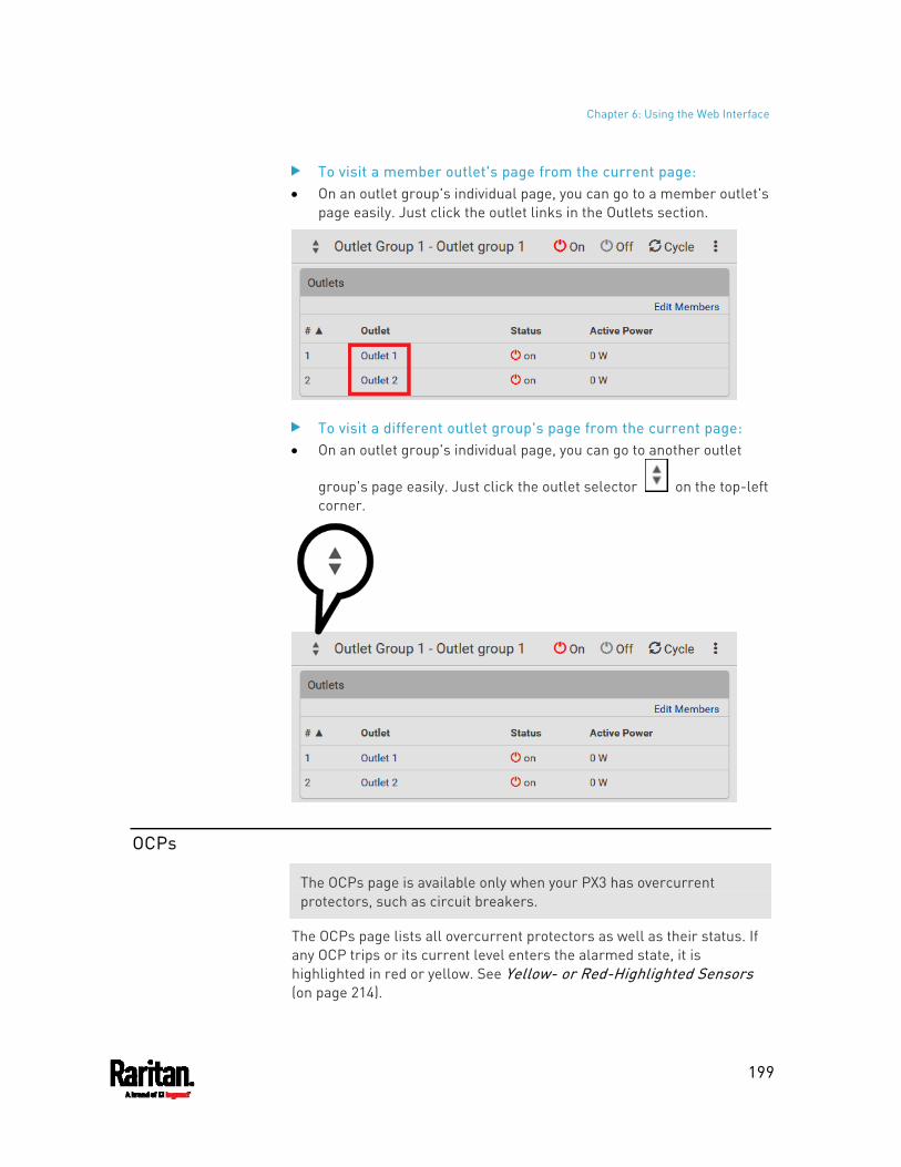
Chapter 6: Using the Web Interface
199
To visit a member outlet's page from the current page: On an outlet group's individual page, you can go to a member outlet's
page easily. Just click the outlet links in the Outlets section.
To visit a different outlet group's page from the current page: On an outlet group's individual page, you can go to another outlet
group's page easily. Just click the outlet selector on the top-left corner.
OCPs
The OCPs page is available only when your PX3 has overcurrent protectors, such as circuit breakers.
The OCPs page lists all overcurrent protectors as well as their status. If any OCP trips or its current level enters the alarmed state, it is highlighted in red or yellow. See Yellow- or Red-Highlighted Sensors (on page 214).
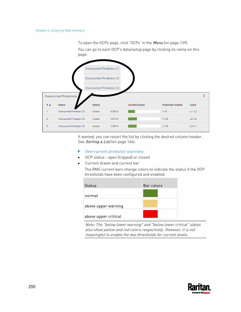
Chapter 6: Using the Web Interface
200
To open the OCPs page, click 'OCPs' in the Menu (on page 139).
You can go to each OCP's data/setup page by clicking its name on this page.
If wanted, you can resort the list by clicking the desired column header. See Sorting a List (on page 144).
Overcurrent protector overview: OCP status - open (tripped) or closed Current drawn and current bar
The RMS current bars change colors to indicate the status if the OCP thresholds have been configured and enabled.
Status Bar colors
normal
above upper warning
above upper critical
Note: The "below lower warning" and "below lower critical" states also show yellow and red colors respectively. However, it is not meaningful to enable the two thresholds for current levels.
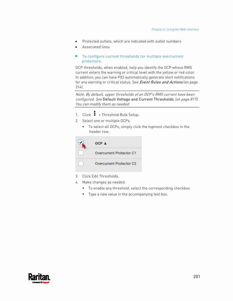
Chapter 6: Using the Web Interface
201
Protected outlets, which are indicated with outlet numbers Associated lines
To configure current thresholds for multiple overcurrent protectors:
OCP thresholds, when enabled, help you identify the OCP whose RMS current enters the warning or critical level with the yellow or red color. In addition, you can have PX3 automatically generate alert notifications for any warning or critical status. See Event Rules and Actions (on page 314).
Note: By default, upper thresholds of an OCP's RMS current have been configured. See Default Voltage and Current Thresholds (on page 817). You can modify them as needed.
1. Click > Threshold Bulk Setup. 2. Select one or multiple OCPs.
To select all OCPs, simply click the topmost checkbox in the header row.
3. Click Edit Thresholds. 4. Make changes as needed.
To enable any threshold, select the corresponding checkbox. Type a new value in the accompanying text box.
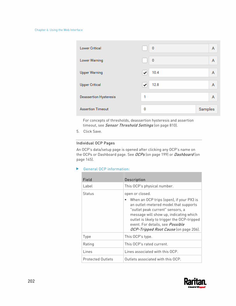
Chapter 6: Using the Web Interface
202
For concepts of thresholds, deassertion hysteresis and assertion timeout, see Sensor Threshold Settings (on page 810).
5. Click Save.
Individual OCP Pages
An OCP's data/setup page is opened after clicking any OCP's name on the OCPs or Dashboard page. See OCPs (on page 199) or Dashboard (on page 145).
General OCP information:
Field Description
Label This OCP's physical number.
Status open or closed. When an OCP trips (open), if your PX3 is
an outlet-metered model that supports "outlet peak current" sensors, a message will show up, indicating which outlet is likely to trigger the OCP-tripped event. For details, see Possible OCP-Tripped Root Cause (on page 206).
Type This OCP's type.
Rating This OCP's rated current.
Lines Lines associated with this OCP.
Protected Outlets Outlets associated with this OCP.
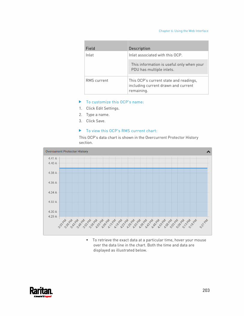
Chapter 6: Using the Web Interface
203
Field Description
Inlet Inlet associated with this OCP.
This information is useful only when your PDU has multiple inlets.
RMS current This OCP's current state and readings, including current drawn and current remaining.
To customize this OCP's name: 1. Click Edit Settings. 2. Type a name. 3. Click Save.
To view this OCP's RMS current chart:
This OCP's data chart is shown in the Overcurrent Protector History section.
To retrieve the exact data at a particular time, hover your mouse
over the data line in the chart. Both the time and data are displayed as illustrated below.
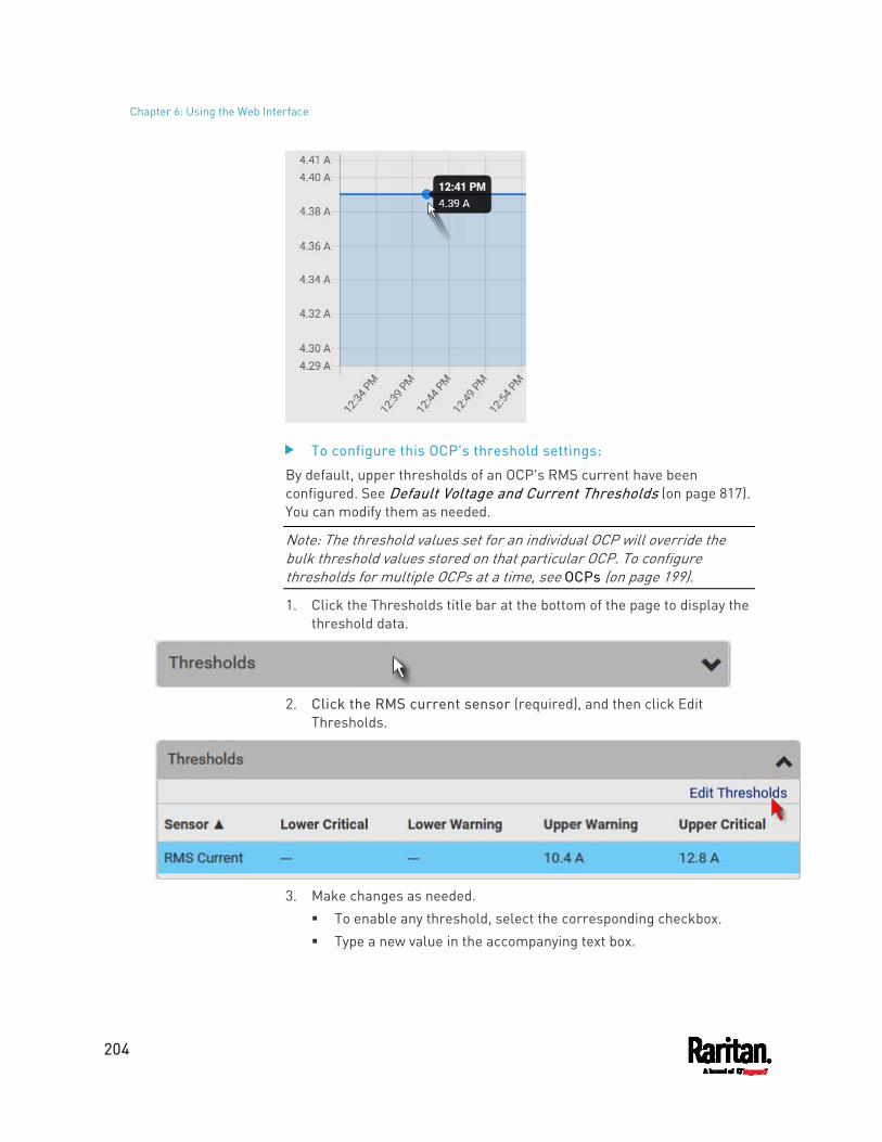
Chapter 6: Using the Web Interface
204
To configure this OCP's threshold settings:
By default, upper thresholds of an OCP's RMS current have been configured. See Default Voltage and Current Thresholds (on page 817). You can modify them as needed.
Note: The threshold values set for an individual OCP will override the bulk threshold values stored on that particular OCP. To configure thresholds for multiple OCPs at a time, see OCPs (on page 199).
1. Click the Thresholds title bar at the bottom of the page to display the threshold data.
2. Click the RMS current sensor (required), and then click Edit
Thresholds.
3. Make changes as needed.
To enable any threshold, select the corresponding checkbox. Type a new value in the accompanying text box.
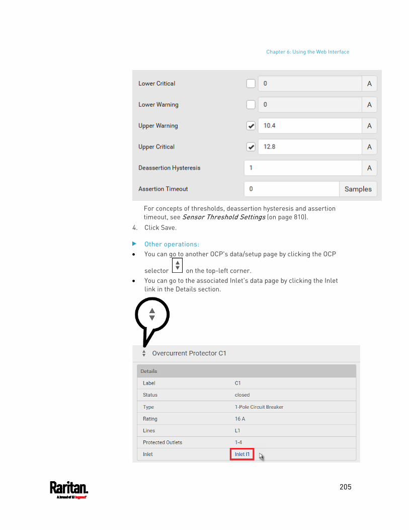
Chapter 6: Using the Web Interface
205
For concepts of thresholds, deassertion hysteresis and assertion timeout, see Sensor Threshold Settings (on page 810).
4. Click Save.
Other operations: You can go to another OCP's data/setup page by clicking the OCP
selector on the top-left corner. You can go to the associated Inlet's data page by clicking the Inlet
link in the Details section.
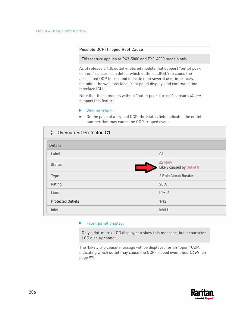
Chapter 6: Using the Web Interface
206
Possible OCP-Tripped Root Cause
This feature applies to PX3-5000 and PX3-4000 models only.
As of release 3.4.0, outlet-metered models that support "outlet peak current" sensors can detect which outlet is LIKELY to cause the associated OCP to trip, and indicate it on several user interfaces, including the web interface, front panel display, and command line interface (CLI).
Note that those models without "outlet peak current" sensors do not support this feature.
Web interface: On the page of a tripped OCP, the Status field indicates the outlet
number that may cause the OCP-tripped event.
Front panel display:
Only a dot-matrix LCD display can show this message, but a character LCD display cannot.
The 'Likely trip cause' message will be displayed for an "open" OCP, indicating which outlet may cause the OCP-tripped event. See OCPs (on page 97).
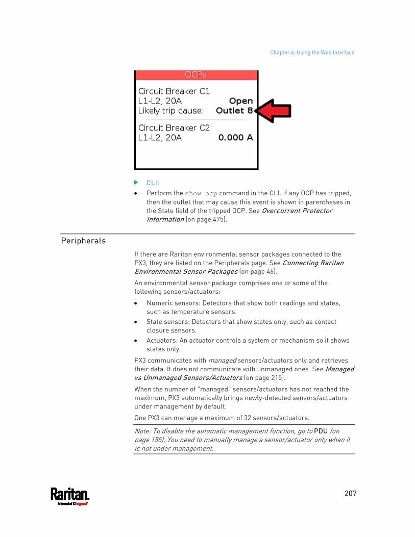
Chapter 6: Using the Web Interface
207
CLI: Perform the show ocp command in the CLI. If any OCP has tripped,
then the outlet that may cause this event is shown in parentheses in the State field of the tripped OCP. See Overcurrent Protector Information (on page 475).
Peripherals
If there are Raritan environmental sensor packages connected to the PX3, they are listed on the Peripherals page. See Connecting Raritan Environmental Sensor Packages (on page 46).
An environmental sensor package comprises one or some of the following sensors/actuators:
Numeric sensors: Detectors that show both readings and states, such as temperature sensors.
State sensors: Detectors that show states only, such as contact closure sensors.
Actuators: An actuator controls a system or mechanism so it shows states only.
PX3 communicates with managed sensors/actuators only and retrieves their data. It does not communicate with unmanaged ones. See Managed vs Unmanaged Sensors/Actuators (on page 215).
When the number of "managed" sensors/actuators has not reached the maximum, PX3 automatically brings newly-detected sensors/actuators under management by default.
One PX3 can manage a maximum of 32 sensors/actuators.
Note: To disable the automatic management function, go to PDU (on page 155). You need to manually manage a sensor/actuator only when it is not under management.
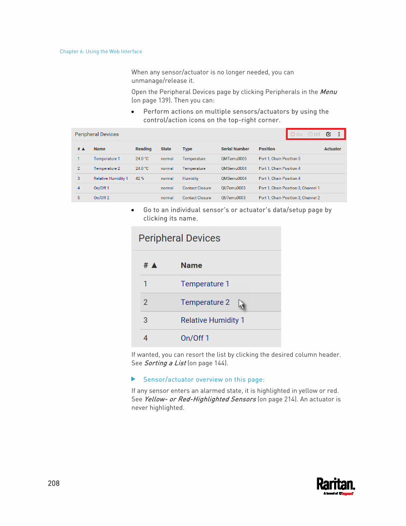
Chapter 6: Using the Web Interface
208
When any sensor/actuator is no longer needed, you can unmanage/release it.
Open the Peripheral Devices page by clicking Peripherals in the Menu (on page 139). Then you can:
Perform actions on multiple sensors/actuators by using the control/action icons on the top-right corner.
Go to an individual sensor's or actuator's data/setup page by
clicking its name.
If wanted, you can resort the list by clicking the desired column header. See Sorting a List (on page 144).
Sensor/actuator overview on this page:
If any sensor enters an alarmed state, it is highlighted in yellow or red. See Yellow- or Red-Highlighted Sensors (on page 214). An actuator is never highlighted.
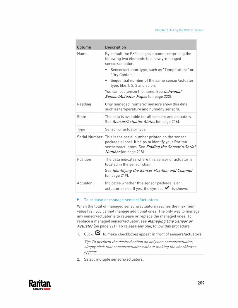
Chapter 6: Using the Web Interface
209
Column Description
Name By default the PX3 assigns a name comprising the following two elements to a newly-managed sensor/actuator. Sensor/actuator type, such as "Temperature" or
"Dry Contact." Sequential number of the same sensor/actuator
type, like 1, 2, 3 and so on. You can customize the name. See Individual Sensor/Actuator Pages (on page 222).
Reading Only managed 'numeric' sensors show this data, such as temperature and humidity sensors.
State The data is available for all sensors and actuators. See Sensor/Actuator States (on page 216).
Type Sensor or actuator type.
Serial Number This is the serial number printed on the sensor package's label. It helps to identify your Raritan sensors/actuators. See Finding the Sensor's Serial Number (on page 218).
Position The data indicates where this sensor or actuator is located in the sensor chain. See Identifying the Sensor Position and Channel (on page 219).
Actuator Indicates whether this sensor package is an actuator or not. If yes, the symbol is shown.
To release or manage sensors/actuators:
When the total of managed sensors/actuators reaches the maximum value (32), you cannot manage additional ones. The only way to manage any sensor/actuator is to release or replace the managed ones. To replace a managed sensor/actuator, see Managing One Sensor or Actuator (on page 221). To release any one, follow this procedure.
1. Click to make checkboxes appear in front of sensors/actuators.
Tip: To perform the desired action on only one sensor/actuator, simply click that sensor/actuator without making the checkboxes appear.
2. Select multiple sensors/actuators.
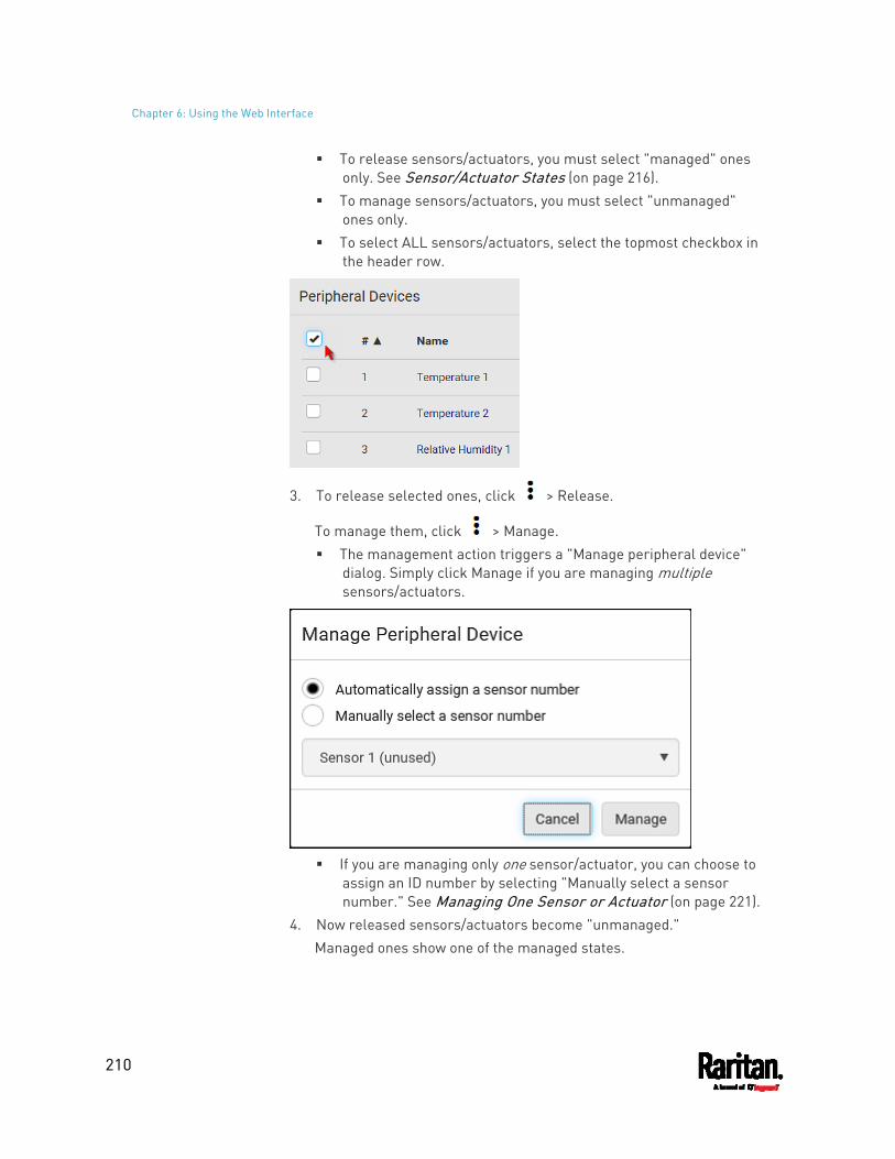
Chapter 6: Using the Web Interface
210
To release sensors/actuators, you must select "managed" ones only. See Sensor/Actuator States (on page 216).
To manage sensors/actuators, you must select "unmanaged" ones only.
To select ALL sensors/actuators, select the topmost checkbox in the header row.
3. To release selected ones, click > Release.
To manage them, click > Manage. The management action triggers a "Manage peripheral device"
dialog. Simply click Manage if you are managing multiple sensors/actuators.
If you are managing only one sensor/actuator, you can choose to
assign an ID number by selecting "Manually select a sensor number." See Managing One Sensor or Actuator (on page 221).
4. Now released sensors/actuators become "unmanaged." Managed ones show one of the managed states.
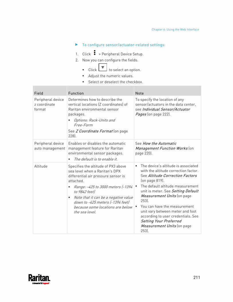
Chapter 6: Using the Web Interface
211
To configure sensor/actuator-related settings:
1. Click > Peripheral Device Setup. 2. Now you can configure the fields.
Click to select an option. Adjust the numeric values. Select or deselect the checkbox.
Field Function Note
Peripheral device z coordinate format
Determines how to describe the vertical locations (Z coordinates) of Raritan environmental sensor packages. Options: Rack-Units and
Free-Form See Z Coordinate Format (on page 228).
To specify the location of any sensor/actuators in the data center, see Individual Sensor/Actuator Pages (on page 222).
Peripheral device auto management
Enables or disables the automatic management feature for Raritan environmental sensor packages. The default is to enable it.
See How the Automatic Management Function Works (on page 220).
Altitude Specifies the altitude of PX3 above sea level when a Raritan's DPX differential air pressure sensor is attached. Range: -425 to 3000 meters (-1394
to 9842 feet) Note that it can be a negative value
down to -425 meters (-1394 feet) because some locations are below the sea level.
The device's altitude is associated with the altitude correction factor. See Altitude Correction Factors (on page 819).
The default altitude measurement unit is meter. See Setting Default Measurement Units (on page 253).
You can have the measurement unit vary between meter and foot according to user credentials. See Setting Your Preferred Measurement Units (on page 253).
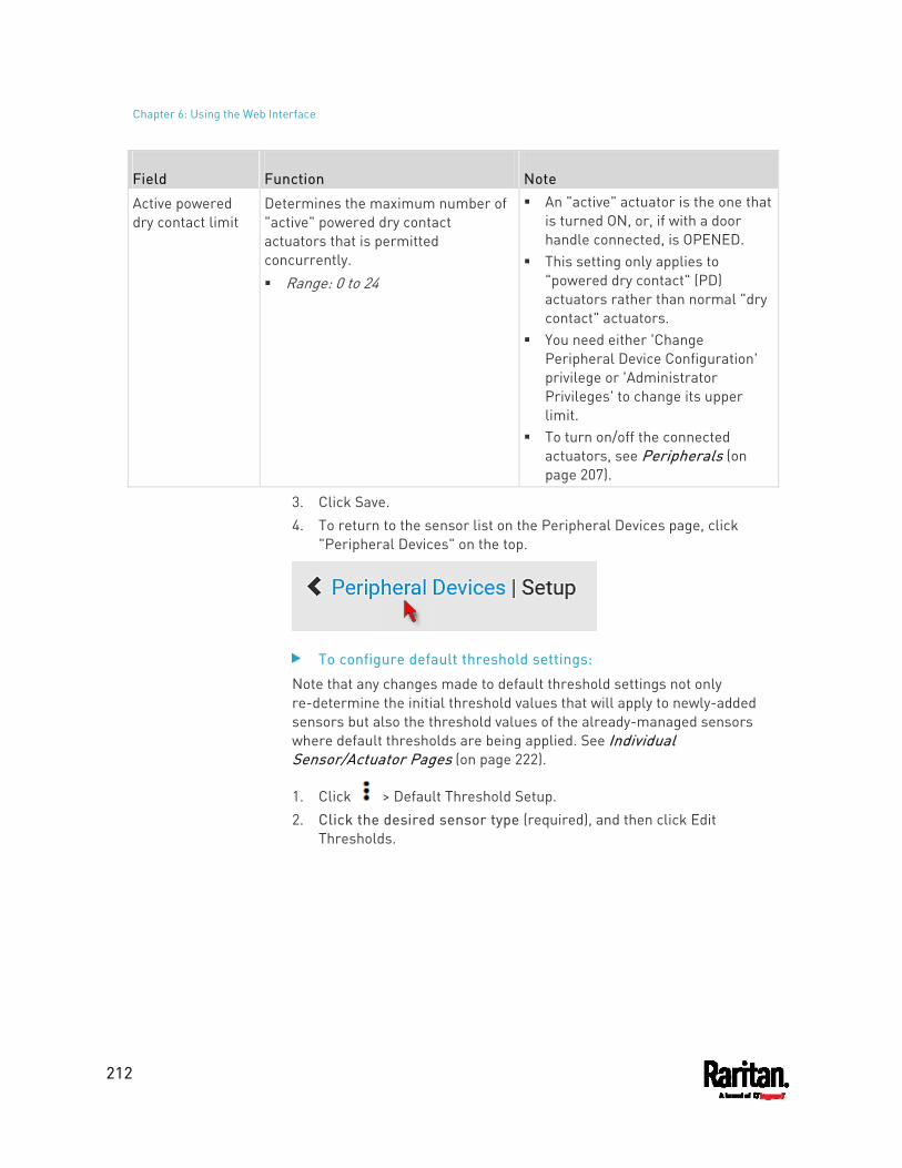
Chapter 6: Using the Web Interface
212
Field Function Note
Active powered dry contact limit
Determines the maximum number of "active" powered dry contact actuators that is permitted concurrently. Range: 0 to 24
An "active" actuator is the one that is turned ON, or, if with a door handle connected, is OPENED.
This setting only applies to "powered dry contact" (PD) actuators rather than normal "dry contact" actuators.
You need either 'Change Peripheral Device Configuration' privilege or 'Administrator Privileges' to change its upper limit.
To turn on/off the connected actuators, see Peripherals (on page 207).
3. Click Save. 4. To return to the sensor list on the Peripheral Devices page, click
"Peripheral Devices" on the top.
To configure default threshold settings:
Note that any changes made to default threshold settings not only re-determine the initial threshold values that will apply to newly-added sensors but also the threshold values of the already-managed sensors where default thresholds are being applied. See Individual Sensor/Actuator Pages (on page 222).
1. Click > Default Threshold Setup. 2. Click the desired sensor type (required), and then click Edit
Thresholds.
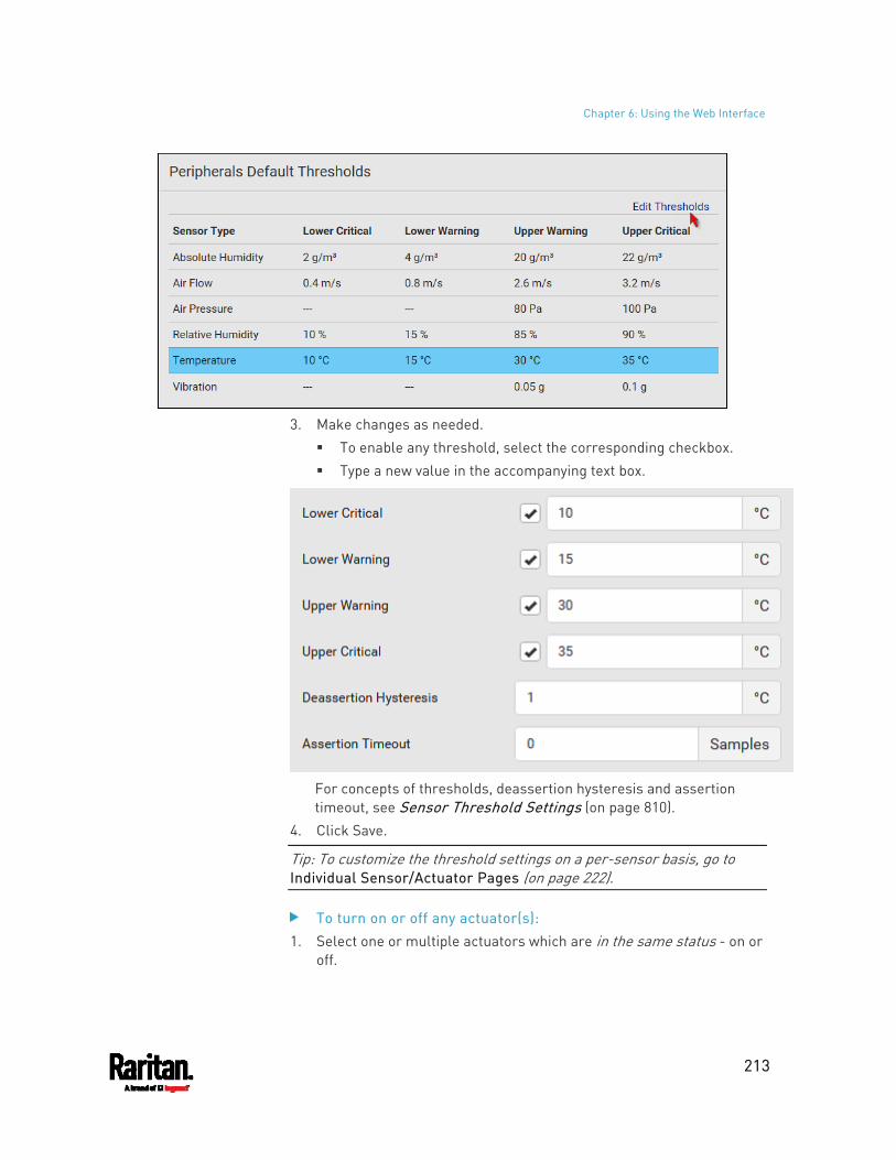
Chapter 6: Using the Web Interface
213
3. Make changes as needed.
To enable any threshold, select the corresponding checkbox. Type a new value in the accompanying text box.
For concepts of thresholds, deassertion hysteresis and assertion timeout, see Sensor Threshold Settings (on page 810).
4. Click Save.
Tip: To customize the threshold settings on a per-sensor basis, go to Individual Sensor/Actuator Pages (on page 222).
To turn on or off any actuator(s): 1. Select one or multiple actuators which are in the same status - on or
off.
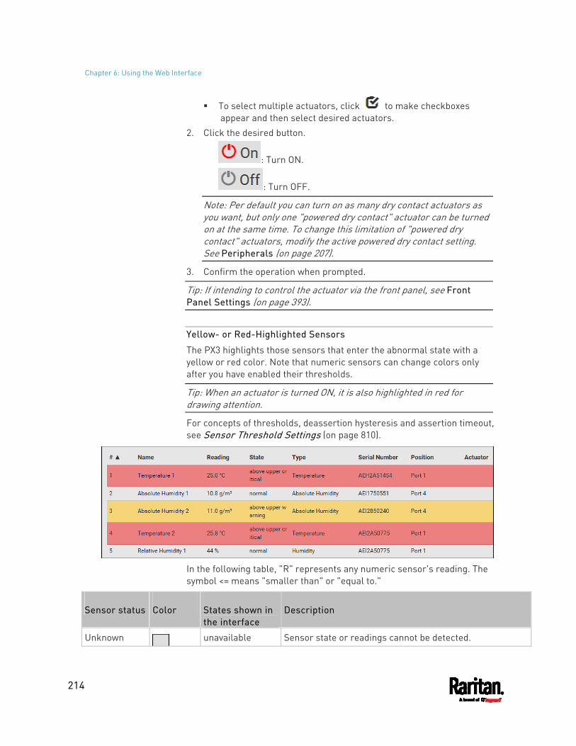
Chapter 6: Using the Web Interface
214
To select multiple actuators, click to make checkboxes appear and then select desired actuators.
2. Click the desired button.
: Turn ON.
: Turn OFF.
Note: Per default you can turn on as many dry contact actuators as you want, but only one "powered dry contact" actuator can be turned on at the same time. To change this limitation of "powered dry contact" actuators, modify the active powered dry contact setting. See Peripherals (on page 207).
3. Confirm the operation when prompted.
Tip: If intending to control the actuator via the front panel, see Front Panel Settings (on page 393).
Yellow- or Red-Highlighted Sensors
The PX3 highlights those sensors that enter the abnormal state with a yellow or red color. Note that numeric sensors can change colors only after you have enabled their thresholds.
Tip: When an actuator is turned ON, it is also highlighted in red for drawing attention.
For concepts of thresholds, deassertion hysteresis and assertion timeout, see Sensor Threshold Settings (on page 810).
In the following table, "R" represents any numeric sensor's reading. The symbol <= means "smaller than" or "equal to."
Sensor status Color States shown in the interface
Description
Unknown unavailable Sensor state or readings cannot be detected.
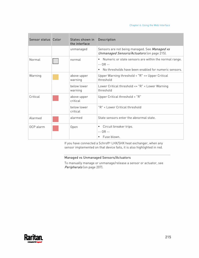
Chapter 6: Using the Web Interface
215
Sensor status Color States shown in the interface
Description
unmanaged Sensors are not being managed. See Managed vs Unmanaged Sensors/Actuators (on page 215).
Normal
normal Numeric or state sensors are within the normal range.-- OR -- No thresholds have been enabled for numeric sensors.
above upper warning
Upper Warning threshold < "R" <= Upper Critical threshold
Warning
below lower warning
Lower Critical threshold <= "R" < Lower Warning threshold
above upper critical
Upper Critical threshold < "R" Critical
below lower critical
"R" < Lower Critical threshold
Alarmed
alarmed State sensors enter the abnormal state.
OCP alarm
Open Circuit breaker trips. -- OR -- Fuse blown.
If you have connected a Schroff® LHX/SHX heat exchanger, when any sensor implemented on that device fails, it is also highlighted in red.
Managed vs Unmanaged Sensors/Actuators
To manually manage or unmanage/release a sensor or actuator, see Peripherals (on page 207).
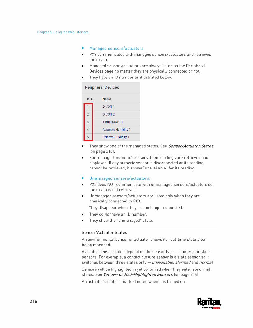
Chapter 6: Using the Web Interface
216
Managed sensors/actuators: PX3 communicates with managed sensors/actuators and retrieves
their data. Managed sensors/actuators are always listed on the Peripheral
Devices page no matter they are physically connected or not. They have an ID number as illustrated below.
They show one of the managed states. See Sensor/Actuator States
(on page 216). For managed 'numeric' sensors, their readings are retrieved and
displayed. If any numeric sensor is disconnected or its reading cannot be retrieved, it shows "unavailable" for its reading.
Unmanaged sensors/actuators: PX3 does NOT communicate with unmanaged sensors/actuators so
their data is not retrieved. Unmanaged sensors/actuators are listed only when they are
physically connected to PX3. They disappear when they are no longer connected.
They do not have an ID number. They show the "unmanaged" state.
Sensor/Actuator States
An environmental sensor or actuator shows its real-time state after being managed.
Available sensor states depend on the sensor type -- numeric or state sensors. For example, a contact closure sensor is a state sensor so it switches between three states only -- unavailable, alarmed and normal. Sensors will be highlighted in yellow or red when they enter abnormal states. See Yellow- or Red-Highlighted Sensors (on page 214).
An actuator's state is marked in red when it is turned on.
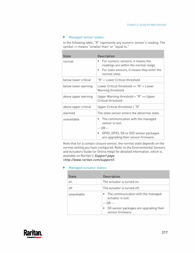
Chapter 6: Using the Web Interface
217
Managed sensor states:
In the following table, "R" represents any numeric sensor's reading. The symbol <= means "smaller than" or "equal to."
State Description
normal For numeric sensors, it means the readings are within the normal range.
For state sensors, it means they enter the normal state.
below lower critical "R" < Lower Critical threshold
below lower warning Lower Critical threshold <= "R" < Lower Warning threshold
above upper warning Upper Warning threshold < "R" <= Upper Critical threshold
above upper critical Upper Critical threshold < "R"
alarmed The state sensor enters the abnormal state.
unavailable The communication with the managed sensor is lost.
-- OR -- DPX2, DPX3, DX or DX2 sensor packages
are upgrading their sensor firmware.
Note that for a contact closure sensor, the normal state depends on the normal setting you have configured. Refer to the Environmental Sensors and Actuators Guide (or Online Help) for detailed information, which is available on Raritan's Support page (http://www.raritan.com/support/).
Managed actuator states:
State Description
on The actuator is turned on.
off The actuator is turned off.
unavailable The communication with the managed actuator is lost.
-- OR -- DX sensor packages are upgrading their
sensor firmware.
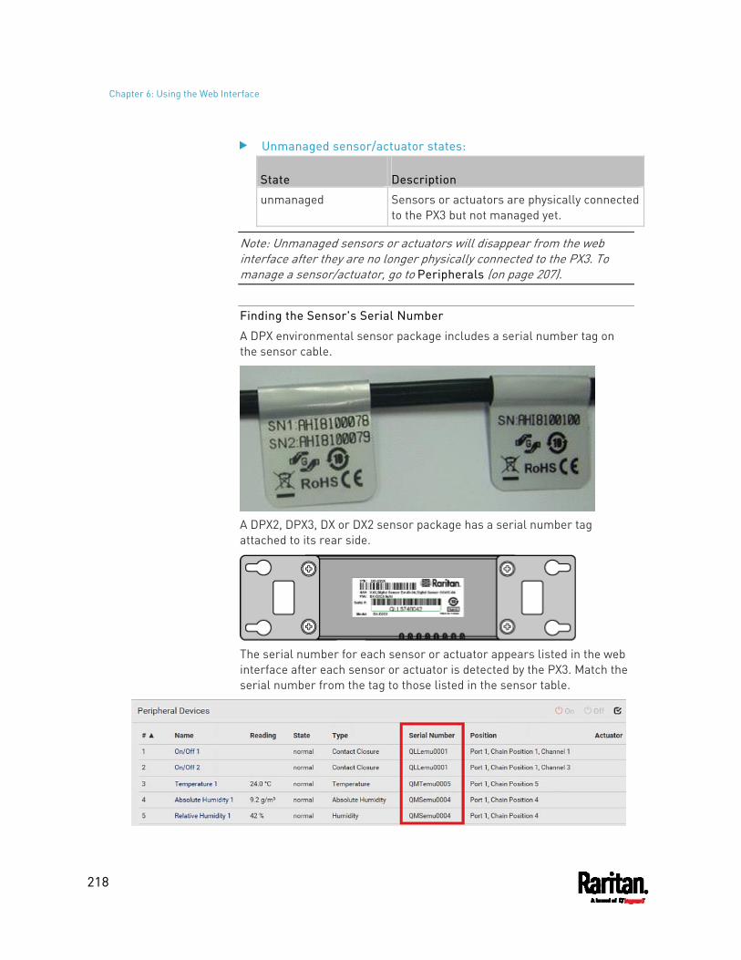
Chapter 6: Using the Web Interface
218
Unmanaged sensor/actuator states:
State Description
unmanaged Sensors or actuators are physically connected to the PX3 but not managed yet.
Note: Unmanaged sensors or actuators will disappear from the web interface after they are no longer physically connected to the PX3. To manage a sensor/actuator, go to Peripherals (on page 207).
Finding the Sensor's Serial Number
A DPX environmental sensor package includes a serial number tag on the sensor cable.
A DPX2, DPX3, DX or DX2 sensor package has a serial number tag attached to its rear side.
The serial number for each sensor or actuator appears listed in the web interface after each sensor or actuator is detected by the PX3. Match the serial number from the tag to those listed in the sensor table.
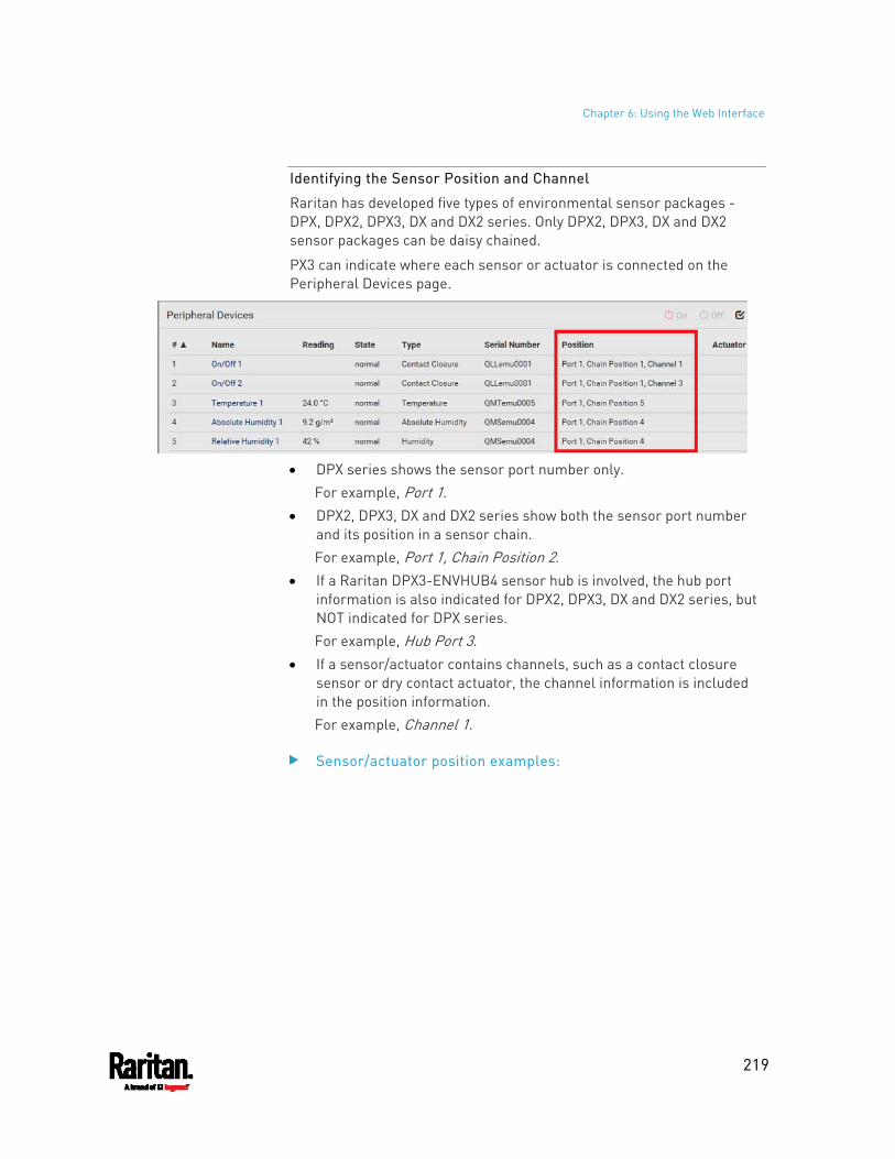
Chapter 6: Using the Web Interface
219
Identifying the Sensor Position and Channel
Raritan has developed five types of environmental sensor packages - DPX, DPX2, DPX3, DX and DX2 series. Only DPX2, DPX3, DX and DX2 sensor packages can be daisy chained.
PX3 can indicate where each sensor or actuator is connected on the Peripheral Devices page.
DPX series shows the sensor port number only.
For example, Port 1. DPX2, DPX3, DX and DX2 series show both the sensor port number
and its position in a sensor chain. For example, Port 1, Chain Position 2.
If a Raritan DPX3-ENVHUB4 sensor hub is involved, the hub port information is also indicated for DPX2, DPX3, DX and DX2 series, but NOT indicated for DPX series. For example, Hub Port 3.
If a sensor/actuator contains channels, such as a contact closure sensor or dry contact actuator, the channel information is included in the position information. For example, Channel 1.
Sensor/actuator position examples:
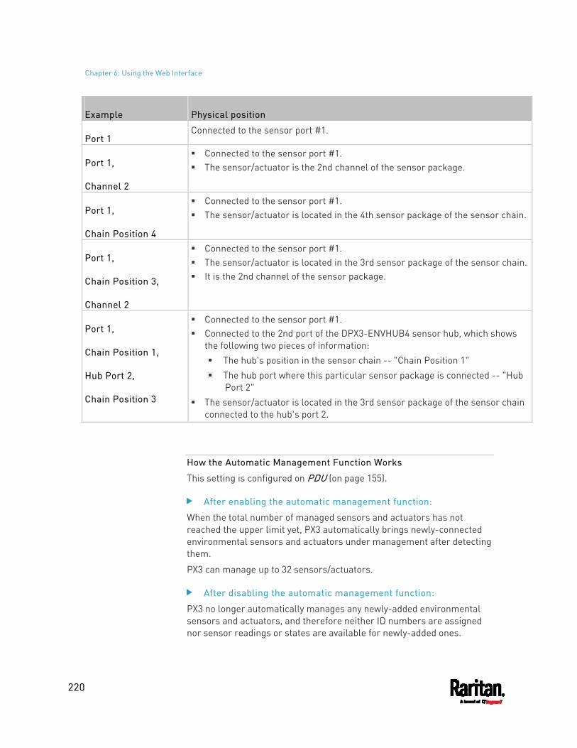
Chapter 6: Using the Web Interface
220
Example Physical position
Port 1 Connected to the sensor port #1.
Port 1,
Channel 2
Connected to the sensor port #1. The sensor/actuator is the 2nd channel of the sensor package.
Port 1,
Chain Position 4
Connected to the sensor port #1. The sensor/actuator is located in the 4th sensor package of the sensor chain.
Port 1,
Chain Position 3,
Channel 2
Connected to the sensor port #1. The sensor/actuator is located in the 3rd sensor package of the sensor chain. It is the 2nd channel of the sensor package.
Port 1,
Chain Position 1,
Hub Port 2,
Chain Position 3
Connected to the sensor port #1. Connected to the 2nd port of the DPX3-ENVHUB4 sensor hub, which shows
the following two pieces of information: The hub's position in the sensor chain -- "Chain Position 1" The hub port where this particular sensor package is connected -- "Hub
Port 2" The sensor/actuator is located in the 3rd sensor package of the sensor chain
connected to the hub's port 2.
How the Automatic Management Function Works
This setting is configured on PDU (on page 155).
After enabling the automatic management function:
When the total number of managed sensors and actuators has not reached the upper limit yet, PX3 automatically brings newly-connected environmental sensors and actuators under management after detecting them.
PX3 can manage up to 32 sensors/actuators.
After disabling the automatic management function:
PX3 no longer automatically manages any newly-added environmental sensors and actuators, and therefore neither ID numbers are assigned nor sensor readings or states are available for newly-added ones.
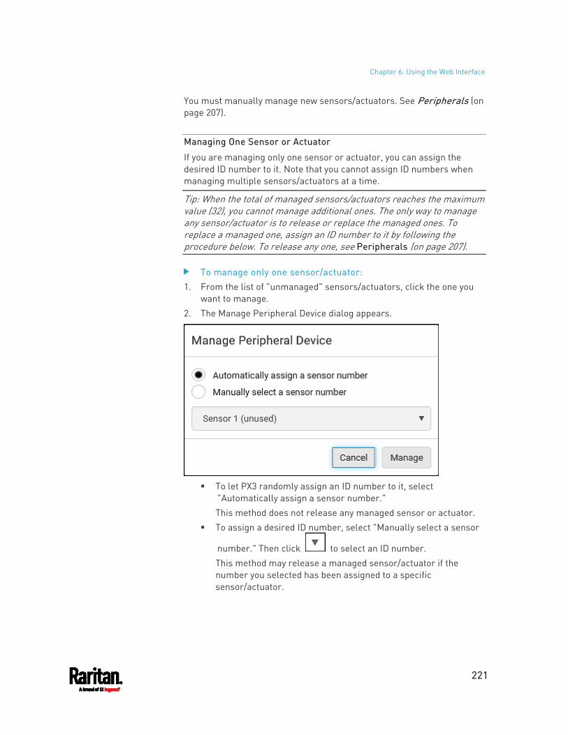
Chapter 6: Using the Web Interface
221
You must manually manage new sensors/actuators. See Peripherals (on page 207).
Managing One Sensor or Actuator
If you are managing only one sensor or actuator, you can assign the desired ID number to it. Note that you cannot assign ID numbers when managing multiple sensors/actuators at a time.
Tip: When the total of managed sensors/actuators reaches the maximum value (32), you cannot manage additional ones. The only way to manage any sensor/actuator is to release or replace the managed ones. To replace a managed one, assign an ID number to it by following the procedure below. To release any one, see Peripherals (on page 207).
To manage only one sensor/actuator: 1. From the list of "unmanaged" sensors/actuators, click the one you
want to manage. 2. The Manage Peripheral Device dialog appears.
To let PX3 randomly assign an ID number to it, select
"Automatically assign a sensor number." This method does not release any managed sensor or actuator.
To assign a desired ID number, select "Manually select a sensor
number." Then click to select an ID number. This method may release a managed sensor/actuator if the number you selected has been assigned to a specific sensor/actuator.
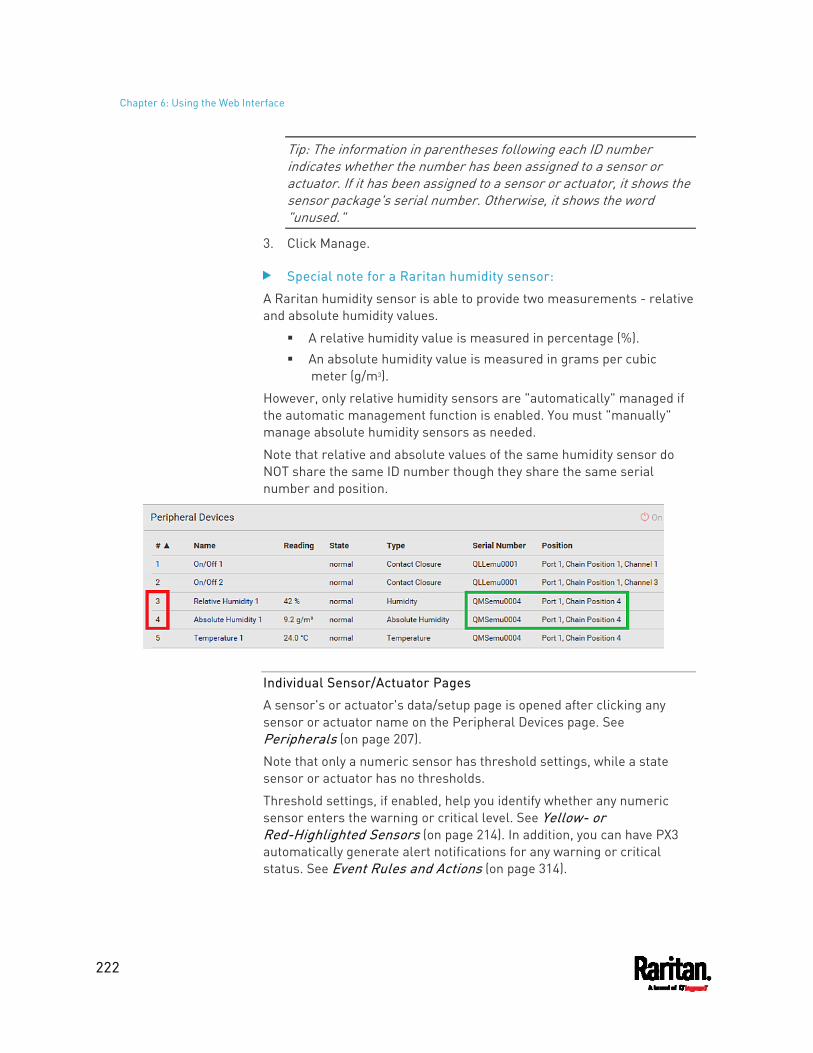
Chapter 6: Using the Web Interface
222
Tip: The information in parentheses following each ID number indicates whether the number has been assigned to a sensor or actuator. If it has been assigned to a sensor or actuator, it shows the sensor package's serial number. Otherwise, it shows the word "unused."
3. Click Manage.
Special note for a Raritan humidity sensor:
A Raritan humidity sensor is able to provide two measurements - relative and absolute humidity values.
A relative humidity value is measured in percentage (%). An absolute humidity value is measured in grams per cubic
meter (g/m3).
However, only relative humidity sensors are "automatically" managed if the automatic management function is enabled. You must "manually" manage absolute humidity sensors as needed.
Note that relative and absolute values of the same humidity sensor do NOT share the same ID number though they share the same serial number and position.
Individual Sensor/Actuator Pages
A sensor's or actuator's data/setup page is opened after clicking any sensor or actuator name on the Peripheral Devices page. See Peripherals (on page 207).
Note that only a numeric sensor has threshold settings, while a state sensor or actuator has no thresholds.
Threshold settings, if enabled, help you identify whether any numeric sensor enters the warning or critical level. See Yellow- or Red-Highlighted Sensors (on page 214). In addition, you can have PX3 automatically generate alert notifications for any warning or critical status. See Event Rules and Actions (on page 314).
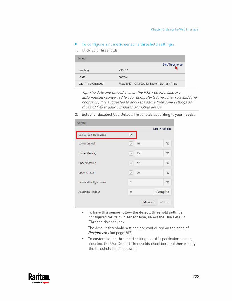
Chapter 6: Using the Web Interface
223
To configure a numeric sensor's threshold settings: 1. Click Edit Thresholds.
Tip: The date and time shown on the PX3 web interface are automatically converted to your computer's time zone. To avoid time confusion, it is suggested to apply the same time zone settings as those of PX3 to your computer or mobile device.
2. Select or deselect Use Default Thresholds according to your needs.
To have this sensor follow the default threshold settings
configured for its own sensor type, select the Use Default Thresholds checkbox. The default threshold settings are configured on the page of Peripherals (on page 207).
To customize the threshold settings for this particular sensor, deselect the Use Default Thresholds checkbox, and then modify the threshold fields below it.
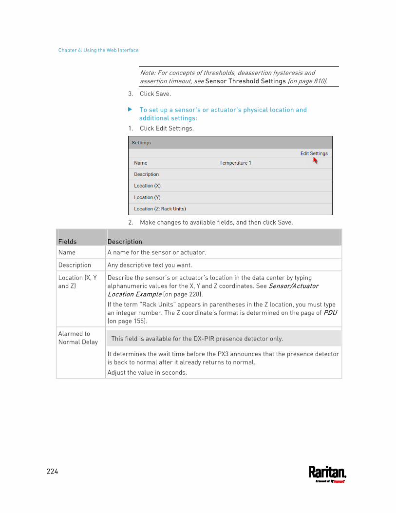
Chapter 6: Using the Web Interface
224
Note: For concepts of thresholds, deassertion hysteresis and assertion timeout, see Sensor Threshold Settings (on page 810).
3. Click Save.
To set up a sensor's or actuator's physical location and additional settings:
1. Click Edit Settings.
2. Make changes to available fields, and then click Save.
Fields Description
Name A name for the sensor or actuator.
Description Any descriptive text you want.
Location (X, Y and Z)
Describe the sensor's or actuator's location in the data center by typing alphanumeric values for the X, Y and Z coordinates. See Sensor/Actuator Location Example (on page 228). If the term "Rack Units" appears in parentheses in the Z location, you must type an integer number. The Z coordinate's format is determined on the page of PDU (on page 155).
Alarmed to Normal Delay This field is available for the DX-PIR presence detector only.
It determines the wait time before the PX3 announces that the presence detector is back to normal after it already returns to normal. Adjust the value in seconds.
Chapter 6: Using the Web Interface
225
Fields Description
Binary Sensor Subtype This field is available for any Raritan contact closure sensor except for
DX2-DH2C2's contact closure sensors.
Determine the sensor type of your contact closure detector. Contact Closure detects the door lock or door open/closed status. Smoke Detection detects the appearance of smoke. Water Detection detects the appearance of water on the floor. Vibration detects the vibration of the floor.
Sensor Polarity This field is available for DX2-CC2 contact closure sensors only.
Determine the normal state of your DX2-CC2. Normal Open: The open status of the connected detector/switch is considered
normal. An alarm is triggered when the detector/switch turns closed. Normal Closed: The closed status of the connected detector/switch is
considered normal. An alarm is triggered when the detector/switch turns opened.
To view a numeric sensor's chart
This sensor's data within the past tens of minutes is shown in the chart. Note that only a numeric sensor has this diagram. State sensors and actuators do not have such data.
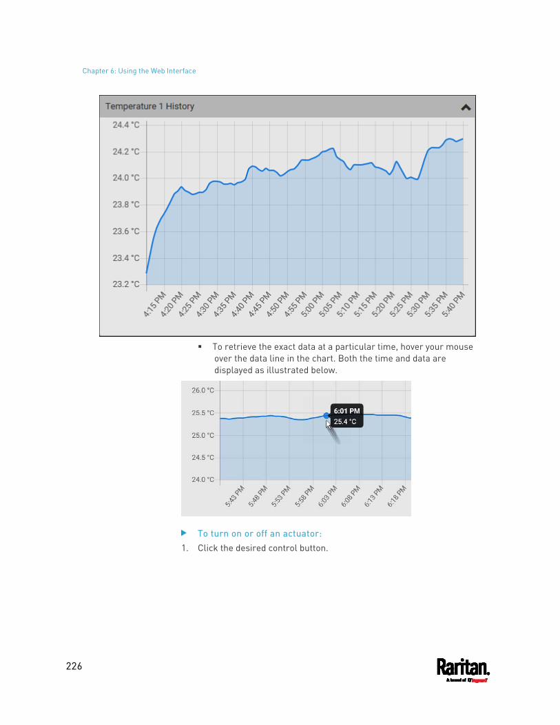
Chapter 6: Using the Web Interface
226
To retrieve the exact data at a particular time, hover your mouse
over the data line in the chart. Both the time and data are displayed as illustrated below.
To turn on or off an actuator: 1. Click the desired control button.
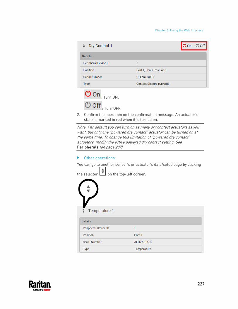
Chapter 6: Using the Web Interface
227
: Turn ON.
: Turn OFF. 2. Confirm the operation on the confirmation message. An actuator's
state is marked in red when it is turned on.
Note: Per default you can turn on as many dry contact actuators as you want, but only one "powered dry contact" actuator can be turned on at the same time. To change this limitation of "powered dry contact" actuators, modify the active powered dry contact setting. See Peripherals (on page 207).
Other operations:
You can go to another sensor's or actuator's data/setup page by clicking
the selector on the top-left corner.
Chapter 6: Using the Web Interface
228
Z Coordinate Format
Z coordinates refer to vertical locations of Raritan's environmental sensor packages. You can use either the number of rack units or a descriptive text to describe Z coordinates.
For a Z coordinate example, see Sensor/Actuator Location Example (on page 228).
To configure Z coordinates: 1. Determine the Z coordinate format on PDU (on page 155). Available Z
coordinate formats include:
Format Description
Rack Units The height of the Z coordinate is measured in standard rack units. When this is selected, you can type a numeric value in the rack unit to describe the Z coordinate of any environmental sensors or actuators.
Free-Form Any alphanumeric string can be used for specifying the Z coordinate. The value comprises 0 to 24 characters.
2. Configure Z coordinates on the Individual Sensor/Actuator Pages (on page 222).
Sensor/Actuator Location Example
Use the X, Y and Z coordinates to describe each sensor's or actuator's physical location in the data center. See Individual Sensor/Actuator Pages (on page 222).
The X, Y and Z values act as additional attributes and are not tied to any specific measurement scheme. Therefore, you can use non-measurement values.
Example:
X = Brown Cabinet Row
Y = Third Rack
Z = Top of Cabinet
Chapter 6: Using the Web Interface
229
Values of the X, Y and Z coordinates: X and Y: They can be any alphanumeric values comprising 0 to 24
characters. Z: When the Z coordinate format is set to Rack Units, it can be any
number ranging from 0 to 60. When its format is set to Free-Form, it can be any alphanumeric value comprising 0 to 24 characters. See Peripherals (on page 207).
Feature Port
The FEATURE port supports connection to the following devices.
Device Description
Asset Strip Raritan asset strips
External Beeper
An external beeper with the RJ-45 socket.
LHX 20 Schroff® LHX-20 heat exchanger.
SHX 30 Schroff® SHX-30 heat exchanger.
LHX 40 Schroff® LHX-40 heat exchanger.
Power CIM This type represents one of the following Raritan products: Raritan power CIM, D2CIM-PWR. This CIM is used
to connect the PX3 to the Raritan digital KVM switch -- Dominion KX II / III.
Dominion KSX II Dominion SX or SX II
When the PX3 detects the connection of any listed device, it replaces 'Feature Port' in the menu with that device's name and shows that device's data/settings instead. See Asset Strip (on page 230), External Beeper (on page 238), Schroff LHX/SHX (on page 238) and Power CIM (on page 243).
When no devices are detected, the PX3 displays the name 'Feature Port" and the Feature Port page shows the message "No device is currently connected."
Open the Feature Port page by clicking it in the Menu (on page 139). From this page, you can enable or disable this port's detection capability, or force it to show a specific device's data/settings even though no device is detected.
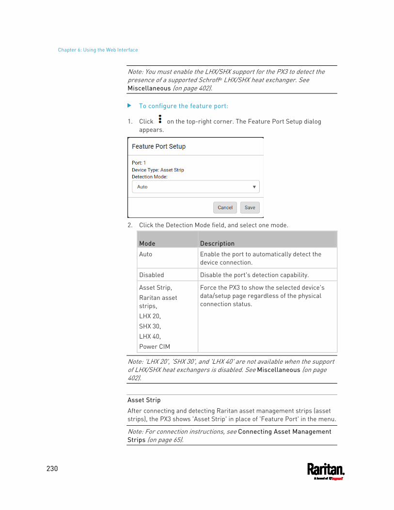
Chapter 6: Using the Web Interface
230
Note: You must enable the LHX/SHX support for the PX3 to detect the presence of a supported Schroff® LHX/SHX heat exchanger. See Miscellaneous (on page 402).
To configure the feature port:
1. Click on the top-right corner. The Feature Port Setup dialog appears.
2. Click the Detection Mode field, and select one mode.
Mode Description
Auto Enable the port to automatically detect the device connection.
Disabled Disable the port's detection capability.
Asset Strip, Raritan asset strips, LHX 20, SHX 30, LHX 40, Power CIM
Force the PX3 to show the selected device's data/setup page regardless of the physical connection status.
Note: 'LHX 20', 'SHX 30', and 'LHX 40' are not available when the support of LHX/SHX heat exchangers is disabled. See Miscellaneous (on page 402).
Asset Strip
After connecting and detecting Raritan asset management strips (asset strips), the PX3 shows 'Asset Strip' in place of 'Feature Port' in the menu.
Note: For connection instructions, see Connecting Asset Management Strips (on page 65).
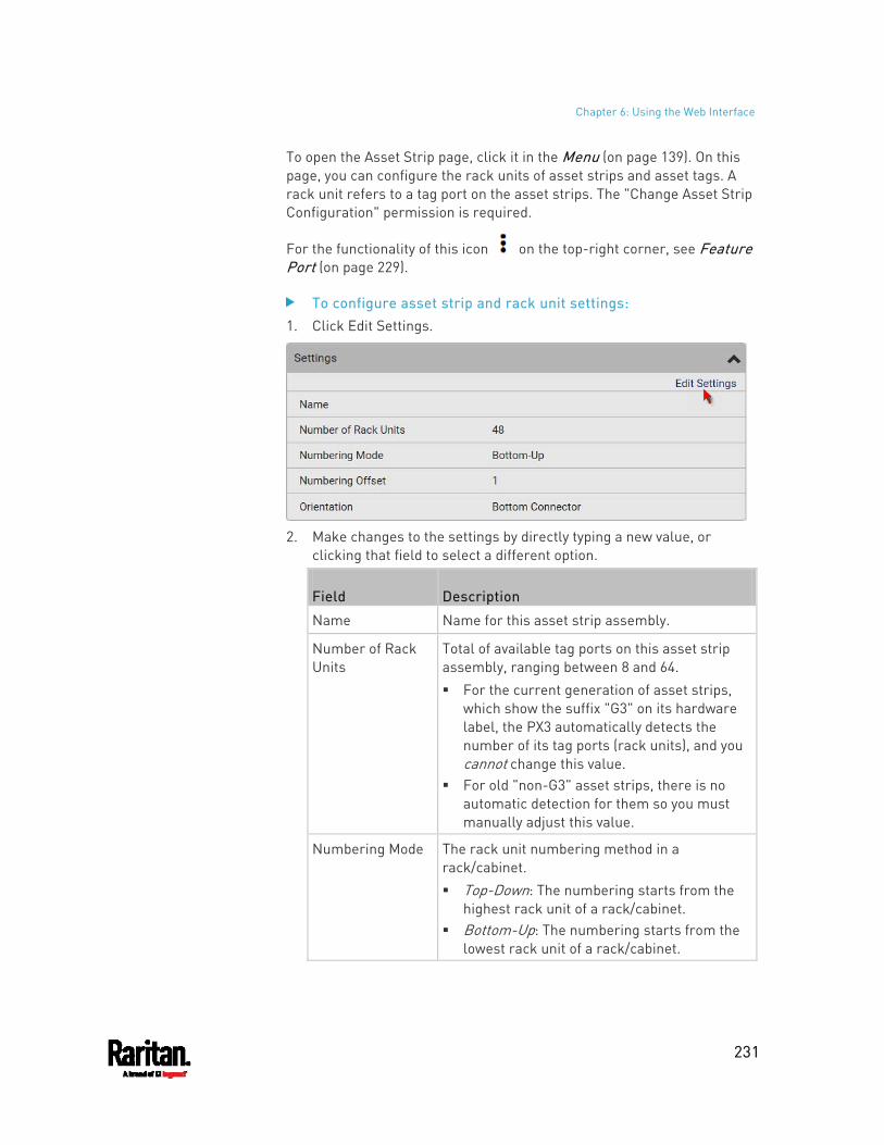
Chapter 6: Using the Web Interface
231
To open the Asset Strip page, click it in the Menu (on page 139). On this page, you can configure the rack units of asset strips and asset tags. A rack unit refers to a tag port on the asset strips. The "Change Asset Strip Configuration" permission is required.
For the functionality of this icon on the top-right corner, see Feature Port (on page 229).
To configure asset strip and rack unit settings: 1. Click Edit Settings.
2. Make changes to the settings by directly typing a new value, or
clicking that field to select a different option.
Field Description
Name Name for this asset strip assembly.
Number of Rack Units
Total of available tag ports on this asset strip assembly, ranging between 8 and 64. For the current generation of asset strips,
which show the suffix "G3" on its hardware label, the PX3 automatically detects the number of its tag ports (rack units), and you cannot change this value.
For old "non-G3" asset strips, there is no automatic detection for them so you must manually adjust this value.
Numbering Mode The rack unit numbering method in a rack/cabinet. Top-Down: The numbering starts from the
highest rack unit of a rack/cabinet. Bottom-Up: The numbering starts from the
lowest rack unit of a rack/cabinet.
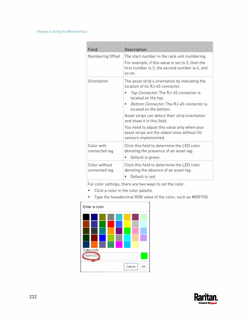
Chapter 6: Using the Web Interface
232
Field Description
Numbering Offset The start number in the rack unit numbering. For example, if this value is set to 3, then the first number is 3, the second number is 4, and so on.
Orientation The asset strip's orientation by indicating the location of its RJ-45 connector. Top Connector: The RJ-45 connector is
located on the top. Bottom Connector: The RJ-45 connector is
located on the bottom. Asset strips can detect their strip orientation and show it in this field. You need to adjust this value only when your asset strips are the oldest ones without tilt sensors implemented.
Color with connected tag
Click this field to determine the LED color denoting the presence of an asset tag. Default is green.
Color without connected tag
Click this field to determine the LED color denoting the absence of an asset tag. Default is red.
For color settings, there are two ways to set the color. Click a color in the color palette. Type the hexadecimal RGB value of the color, such as #00FF00.
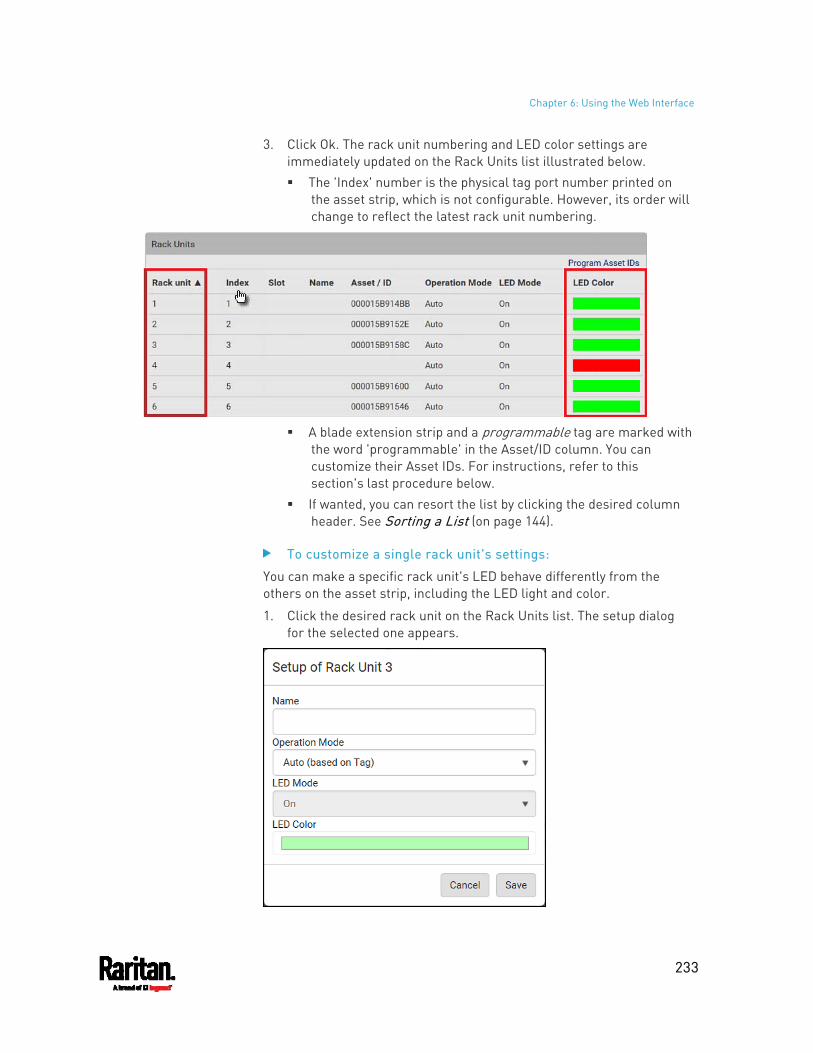
Chapter 6: Using the Web Interface
233
3. Click Ok. The rack unit numbering and LED color settings are immediately updated on the Rack Units list illustrated below. The 'Index' number is the physical tag port number printed on
the asset strip, which is not configurable. However, its order will change to reflect the latest rack unit numbering.
A blade extension strip and a programmable tag are marked with
the word 'programmable' in the Asset/ID column. You can customize their Asset IDs. For instructions, refer to this section's last procedure below.
If wanted, you can resort the list by clicking the desired column header. See Sorting a List (on page 144).
To customize a single rack unit's settings:
You can make a specific rack unit's LED behave differently from the others on the asset strip, including the LED light and color.
1. Click the desired rack unit on the Rack Units list. The setup dialog for the selected one appears.
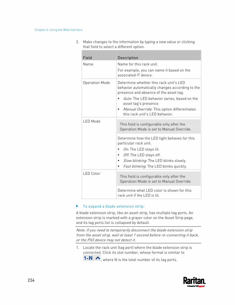
Chapter 6: Using the Web Interface
234
2. Make changes to the information by typing a new value or clicking that field to select a different option.
Field Description
Name Name for this rack unit. For example, you can name it based on the associated IT device.
Operation Mode Determine whether this rack unit's LED behavior automatically changes according to the presence and absence of the asset tag. Auto: The LED behavior varies, based on the
asset tag's presence. Manual Override: This option differentiates
this rack unit's LED behavior.
LED Mode This field is configurable only after the Operation Mode is set to Manual Override.
Determine how the LED light behaves for this particular rack unit. On: The LED stays lit. Off: The LED stays off. Slow blinking: The LED blinks slowly. Fast blinking: The LED blinks quickly.
LED Color This field is configurable only after the Operation Mode is set to Manual Override.
Determine what LED color is shown for this rack unit if the LED is lit.
To expand a blade extension strip:
A blade extension strip, like an asset strip, has multiple tag ports. An extension strip is marked with a grayer color on the Asset Strip page, and its tag ports list is collapsed by default.
Note: If you need to temporarily disconnect the blade extension strip from the asset strip, wait at least 1 second before re-connecting it back, or the PX3 device may not detect it.
1. Locate the rack unit (tag port) where the blade extension strip is connected. Click its slot number, whose format is similar to
, where N is the total number of its tag ports.
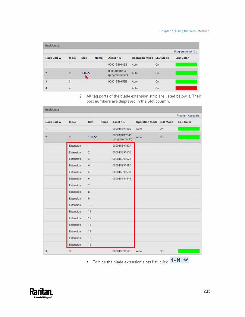
Chapter 6: Using the Web Interface
235
2. All tag ports of the blade extension strip are listed below it. Their
port numbers are displayed in the Slot column.
To hide the blade extension slots list, click .
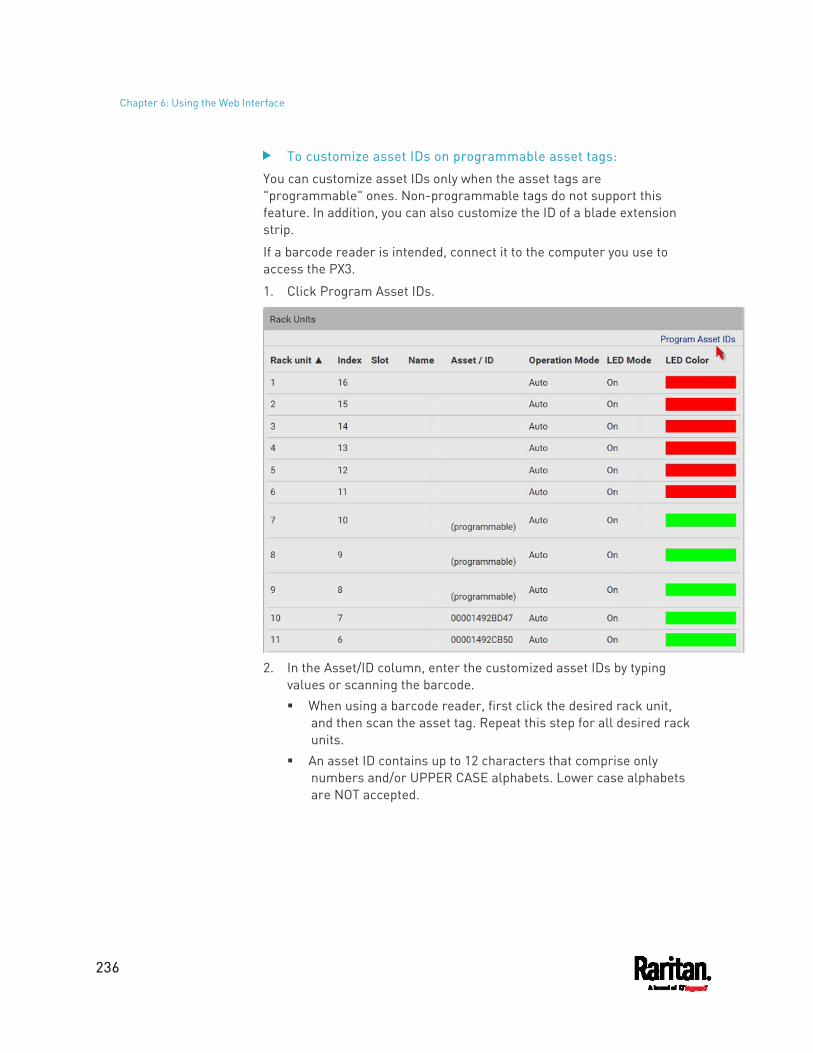
Chapter 6: Using the Web Interface
236
To customize asset IDs on programmable asset tags:
You can customize asset IDs only when the asset tags are "programmable" ones. Non-programmable tags do not support this feature. In addition, you can also customize the ID of a blade extension strip.
If a barcode reader is intended, connect it to the computer you use to access the PX3.
1. Click Program Asset IDs.
2. In the Asset/ID column, enter the customized asset IDs by typing
values or scanning the barcode. When using a barcode reader, first click the desired rack unit,
and then scan the asset tag. Repeat this step for all desired rack units.
An asset ID contains up to 12 characters that comprise only numbers and/or UPPER CASE alphabets. Lower case alphabets are NOT accepted.
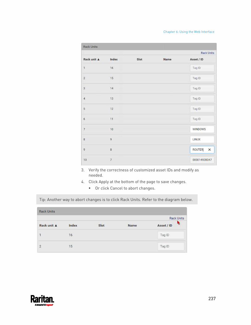
Chapter 6: Using the Web Interface
237
3. Verify the correctness of customized asset IDs and modify as
needed. 4. Click Apply at the bottom of the page to save changes.
Or click Cancel to abort changes.
Tip: Another way to abort changes is to click Rack Units. Refer to the diagram below.
Chapter 6: Using the Web Interface
238
Asset Strip Automatic Firmware Upgrade
After connecting the asset strip to the PX3, it automatically checks its own firmware version against the version of the asset strip firmware stored in the PX3 firmware. If two versions are different, the asset strip automatically starts downloading the new firmware from the PX3 to upgrade its own firmware.
During the firmware upgrade, the following events take place:
The asset strip is completely lit up, with the blinking LEDs cycling through diverse colors.
A firmware upgrade process is indicated in the PX3 web interface. An SNMP trap is sent to indicate the firmware upgrade event.
External Beeper
After connecting and detecting a supported external beeper, the PX3 shows 'External Beeper' in place of 'Feature Port' in the menu.
Note: For connection instructions, see Connecting an External Beeper (on page 77).
To open the External Beeper page, click it in the Menu (on page 139). This page shows an external beeper's status, including:
Number of the FEATURE port where this external beeper is connected
Its device type Its connection status The beeper's state - off or active
For the functionality of this icon on the top-right corner, see Feature Port (on page 229).
Schroff LHX/SHX
You must enable the LHX/SHX support for the PX3 to detect the presence of a supported Schroff® LHX/SHX heat exchanger. See Miscellaneous (on page 402).
After enabling the LHX/SHX support and connecting a supported Schroff® LHX/SHX heat exchanger to the PX3, the PX3 shows the connected device type in place of 'Feature Port' in the menu -- LHX 20, LHX 40 or SHX 30.
Note: For connection instructions, see Connecting a Schroff LHX/SHX Heat Exchanger (on page 77).
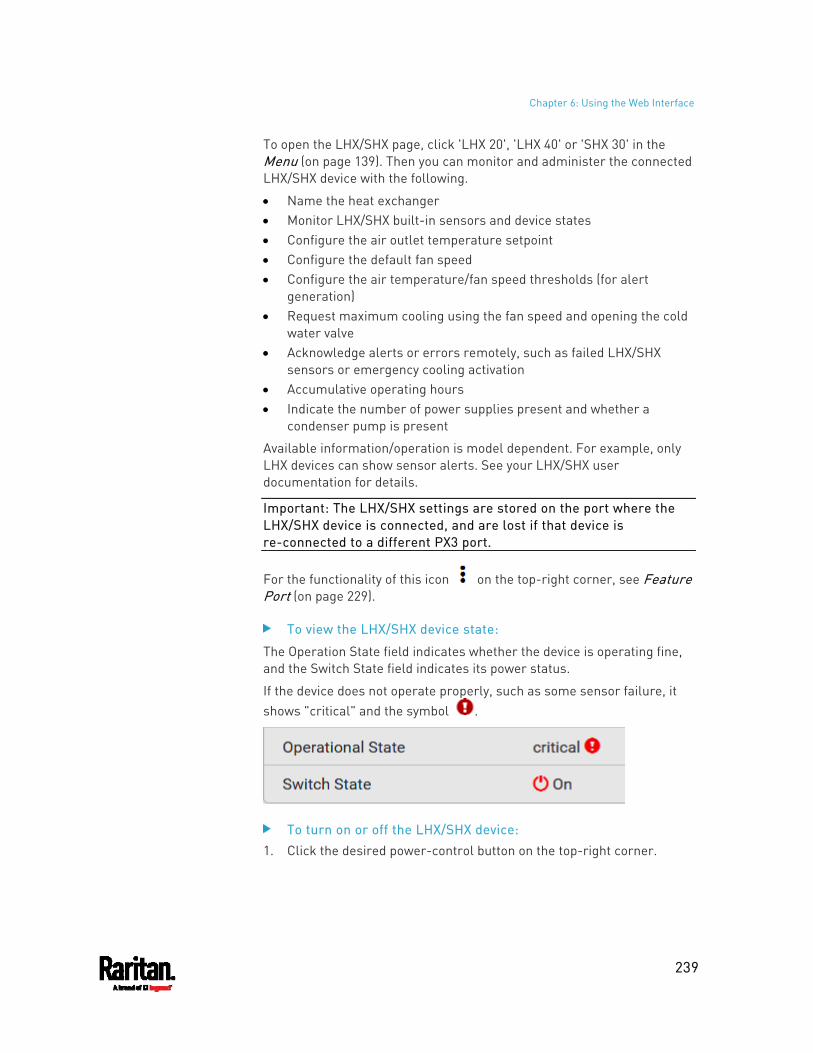
Chapter 6: Using the Web Interface
239
To open the LHX/SHX page, click 'LHX 20', 'LHX 40' or 'SHX 30' in the Menu (on page 139). Then you can monitor and administer the connected LHX/SHX device with the following.
Name the heat exchanger Monitor LHX/SHX built-in sensors and device states Configure the air outlet temperature setpoint Configure the default fan speed Configure the air temperature/fan speed thresholds (for alert
generation) Request maximum cooling using the fan speed and opening the cold
water valve Acknowledge alerts or errors remotely, such as failed LHX/SHX
sensors or emergency cooling activation Accumulative operating hours Indicate the number of power supplies present and whether a
condenser pump is present
Available information/operation is model dependent. For example, only LHX devices can show sensor alerts. See your LHX/SHX user documentation for details.
Important: The LHX/SHX settings are stored on the port where the LHX/SHX device is connected, and are lost if that device is re-connected to a different PX3 port.
For the functionality of this icon on the top-right corner, see Feature Port (on page 229).
To view the LHX/SHX device state:
The Operation State field indicates whether the device is operating fine, and the Switch State field indicates its power status.
If the device does not operate properly, such as some sensor failure, it shows "critical" and the symbol .
To turn on or off the LHX/SHX device: 1. Click the desired power-control button on the top-right corner.
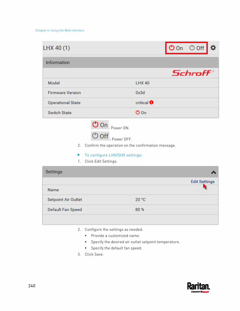
Chapter 6: Using the Web Interface
240
: Power ON.
: Power OFF. 2. Confirm the operation on the confirmation message.
To configure LHX/SHX settings: 1. Click Edit Settings.
2. Configure the settings as needed.
Provide a customized name. Specify the desired air outlet setpoint temperature. Specify the default fan speed.
3. Click Save.
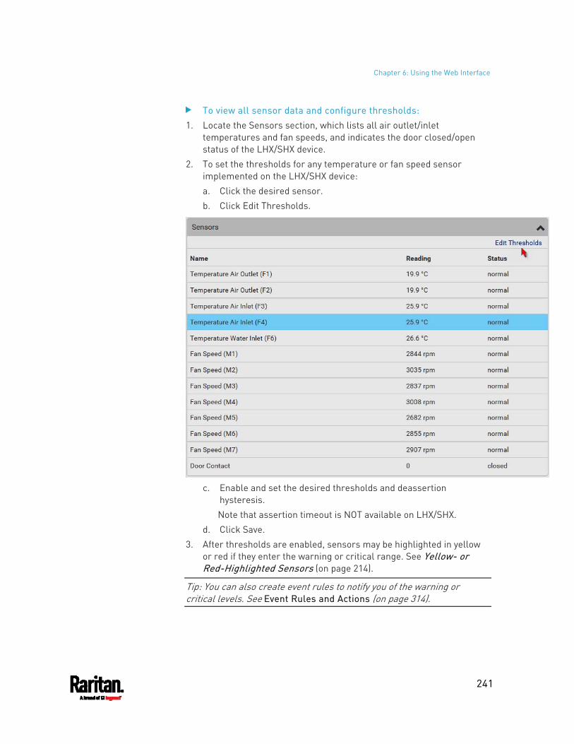
Chapter 6: Using the Web Interface
241
To view all sensor data and configure thresholds: 1. Locate the Sensors section, which lists all air outlet/inlet
temperatures and fan speeds, and indicates the door closed/open status of the LHX/SHX device.
2. To set the thresholds for any temperature or fan speed sensor implemented on the LHX/SHX device: a. Click the desired sensor. b. Click Edit Thresholds.
c. Enable and set the desired thresholds and deassertion
hysteresis. Note that assertion timeout is NOT available on LHX/SHX.
d. Click Save. 3. After thresholds are enabled, sensors may be highlighted in yellow
or red if they enter the warning or critical range. See Yellow- or Red-Highlighted Sensors (on page 214).
Tip: You can also create event rules to notify you of the warning or critical levels. See Event Rules and Actions (on page 314).
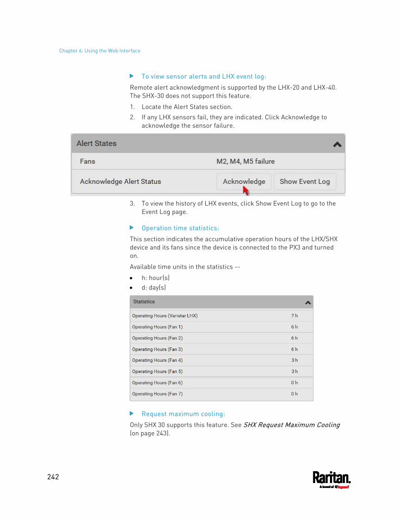
Chapter 6: Using the Web Interface
242
To view sensor alerts and LHX event log:
Remote alert acknowledgment is supported by the LHX-20 and LHX-40. The SHX-30 does not support this feature.
1. Locate the Alert States section. 2. If any LHX sensors fail, they are indicated. Click Acknowledge to
acknowledge the sensor failure.
3. To view the history of LHX events, click Show Event Log to go to the
Event Log page.
Operation time statistics:
This section indicates the accumulative operation hours of the LHX/SHX device and its fans since the device is connected to the PX3 and turned on.
Available time units in the statistics --
h: hour(s) d: day(s)
Request maximum cooling:
Only SHX 30 supports this feature. See SHX Request Maximum Cooling (on page 243).
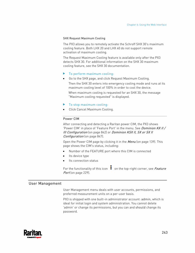
Chapter 6: Using the Web Interface
243
SHX Request Maximum Cooling
The PX3 allows you to remotely activate the Schroff SHX 30's maximum cooling feature. Both LHX 20 and LHX 40 do not support remote activation of maximum cooling.
The Request Maximum Cooling feature is available only after the PX3 detects SHX 30. For additional information on the SHX 30 maximum cooling feature, see the SHX 30 documentation.
To perform maximum cooling: Go to the SHX page, and click Request Maximum Cooling.
Then the SHX 30 enters into emergency cooling mode and runs at its maximum cooling level of 100% in order to cool the device. When maximum cooling is requested for an SHX 30, the message "Maximum cooling requested" is displayed.
To stop maximum cooling: Click Cancel Maximum Cooling.
Power CIM
After connecting and detecting a Raritan power CIM, the PX3 shows 'Power CIM' in place of 'Feature Port' in the menu. See Dominion KX II / III Configuration (on page 842) or Dominion KSX II, SX or SX II Configuration (on page 847).
Open the Power CIM page by clicking it in the Menu (on page 139). This page shows the CIM's status, including:
Number of the FEATURE port where this CIM is connected Its device type Its connection status
For the functionality of this icon on the top-right corner, see Feature Port (on page 229).
User Management
User Management menu deals with user accounts, permissions, and preferred measurement units on a per-user basis.
PX3 is shipped with one built-in administrator account: admin, which is ideal for initial login and system administration. You cannot delete 'admin' or change its permissions, but you can and should change its password.
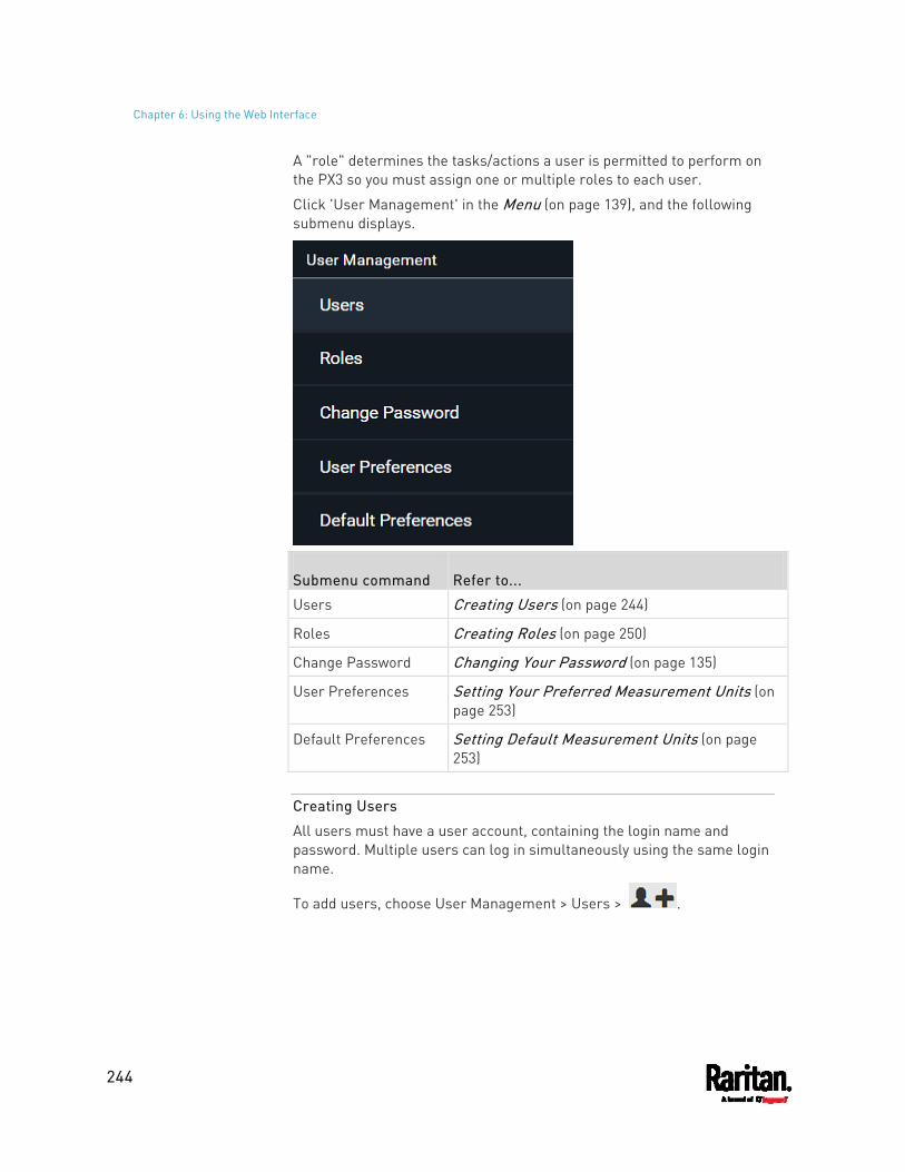
Chapter 6: Using the Web Interface
244
A "role" determines the tasks/actions a user is permitted to perform on the PX3 so you must assign one or multiple roles to each user.
Click 'User Management' in the Menu (on page 139), and the following submenu displays.
Submenu command Refer to...
Users Creating Users (on page 244)
Roles Creating Roles (on page 250)
Change Password Changing Your Password (on page 135)
User Preferences Setting Your Preferred Measurement Units (on page 253)
Default Preferences Setting Default Measurement Units (on page 253)
Creating Users
All users must have a user account, containing the login name and password. Multiple users can log in simultaneously using the same login name.
To add users, choose User Management > Users > .
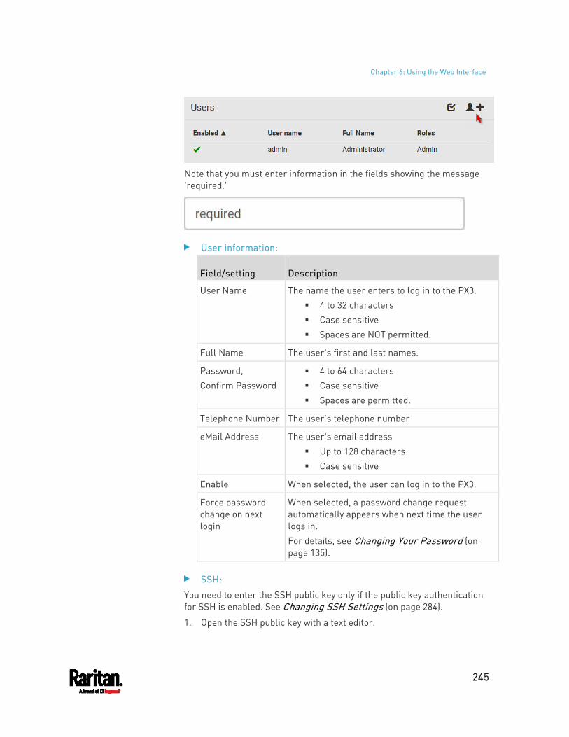
Chapter 6: Using the Web Interface
245
Note that you must enter information in the fields showing the message 'required.'
User information:
Field/setting Description
User Name The name the user enters to log in to the PX3. 4 to 32 characters Case sensitive Spaces are NOT permitted.
Full Name The user's first and last names.
Password, Confirm Password
4 to 64 characters Case sensitive Spaces are permitted.
Telephone Number The user's telephone number
eMail Address The user's email address Up to 128 characters Case sensitive
Enable When selected, the user can log in to the PX3.
Force password change on next login
When selected, a password change request automatically appears when next time the user logs in. For details, see Changing Your Password (on page 135).
SSH:
You need to enter the SSH public key only if the public key authentication for SSH is enabled. See Changing SSH Settings (on page 284).
1. Open the SSH public key with a text editor.
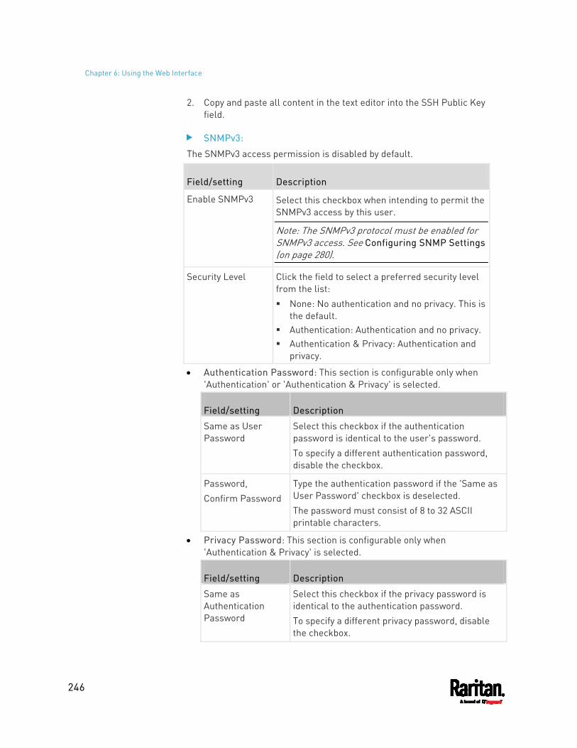
Chapter 6: Using the Web Interface
246
2. Copy and paste all content in the text editor into the SSH Public Key field.
SNMPv3:
The SNMPv3 access permission is disabled by default.
Field/setting Description
Enable SNMPv3 Select this checkbox when intending to permit the SNMPv3 access by this user.
Note: The SNMPv3 protocol must be enabled for SNMPv3 access. See Configuring SNMP Settings (on page 280).
Security Level Click the field to select a preferred security level from the list: None: No authentication and no privacy. This is
the default. Authentication: Authentication and no privacy. Authentication & Privacy: Authentication and
privacy.
Authentication Password: This section is configurable only when 'Authentication' or 'Authentication & Privacy' is selected.
Field/setting Description
Same as User Password
Select this checkbox if the authentication password is identical to the user's password. To specify a different authentication password, disable the checkbox.
Password, Confirm Password
Type the authentication password if the 'Same as User Password' checkbox is deselected. The password must consist of 8 to 32 ASCII printable characters.
Privacy Password: This section is configurable only when 'Authentication & Privacy' is selected.
Field/setting Description
Same as Authentication Password
Select this checkbox if the privacy password is identical to the authentication password. To specify a different privacy password, disable the checkbox.
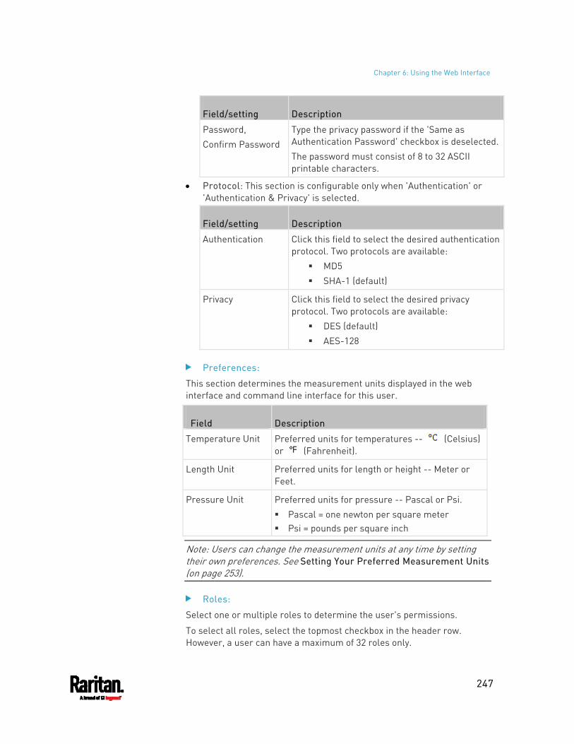
Chapter 6: Using the Web Interface
247
Field/setting Description
Password, Confirm Password
Type the privacy password if the 'Same as Authentication Password' checkbox is deselected.The password must consist of 8 to 32 ASCII printable characters.
Protocol: This section is configurable only when 'Authentication' or 'Authentication & Privacy' is selected.
Field/setting Description
Authentication Click this field to select the desired authentication protocol. Two protocols are available:
MD5 SHA-1 (default)
Privacy Click this field to select the desired privacy protocol. Two protocols are available:
DES (default) AES-128
Preferences:
This section determines the measurement units displayed in the web interface and command line interface for this user.
Field Description
Temperature Unit Preferred units for temperatures -- (Celsius) or (Fahrenheit).
Length Unit Preferred units for length or height -- Meter or Feet.
Pressure Unit Preferred units for pressure -- Pascal or Psi. Pascal = one newton per square meter Psi = pounds per square inch
Note: Users can change the measurement units at any time by setting their own preferences. See Setting Your Preferred Measurement Units (on page 253).
Roles:
Select one or multiple roles to determine the user's permissions.
To select all roles, select the topmost checkbox in the header row. However, a user can have a maximum of 32 roles only.
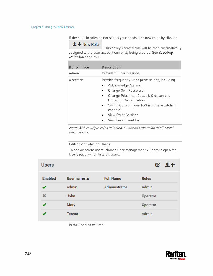
Chapter 6: Using the Web Interface
248
If the built-in roles do not satisfy your needs, add new roles by clicking
. This newly-created role will be then automatically assigned to the user account currently being created. See Creating Roles (on page 250).
Built-in role Description
Admin Provide full permissions.
Operator Provide frequently-used permissions, including: Acknowledge Alarms Change Own Password Change Pdu, Inlet, Outlet & Overcurrent
Protector Configuration Switch Outlet (if your PX3 is outlet-switching
capable) View Event Settings View Local Event Log
Note: With multiple roles selected, a user has the union of all roles' permissions.
Editing or Deleting Users
To edit or delete users, choose User Management > Users to open the Users page, which lists all users.
In the Enabled column:
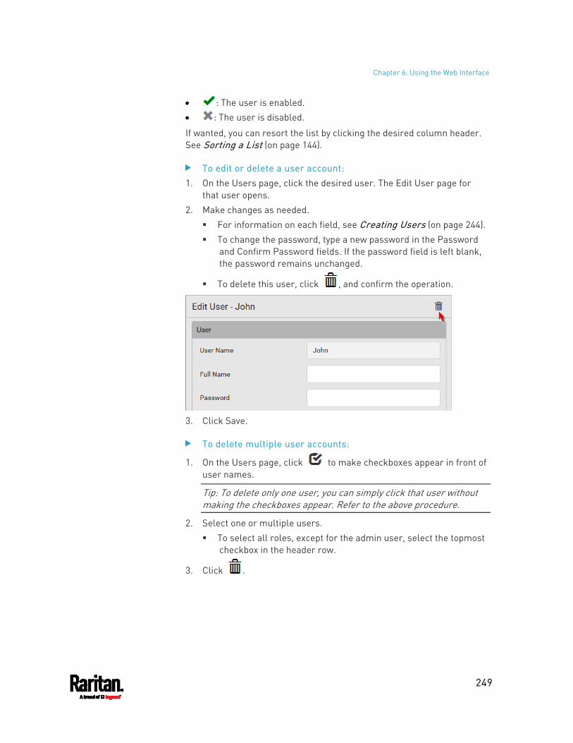
Chapter 6: Using the Web Interface
249
: The user is enabled. : The user is disabled.
If wanted, you can resort the list by clicking the desired column header. See Sorting a List (on page 144).
To edit or delete a user account: 1. On the Users page, click the desired user. The Edit User page for
that user opens. 2. Make changes as needed.
For information on each field, see Creating Users (on page 244). To change the password, type a new password in the Password
and Confirm Password fields. If the password field is left blank, the password remains unchanged.
To delete this user, click , and confirm the operation.
3. Click Save.
To delete multiple user accounts:
1. On the Users page, click to make checkboxes appear in front of user names.
Tip: To delete only one user, you can simply click that user without making the checkboxes appear. Refer to the above procedure.
2. Select one or multiple users. To select all roles, except for the admin user, select the topmost
checkbox in the header row.
3. Click .
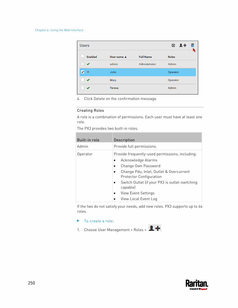
Chapter 6: Using the Web Interface
250
4. Click Delete on the confirmation message.
Creating Roles
A role is a combination of permissions. Each user must have at least one role.
The PX3 provides two built-in roles.
Built-in role Description
Admin Provide full permissions.
Operator Provide frequently-used permissions, including: Acknowledge Alarms Change Own Password Change Pdu, Inlet, Outlet & Overcurrent
Protector Configuration Switch Outlet (if your PX3 is outlet-switching
capable) View Event Settings View Local Event Log
If the two do not satisfy your needs, add new roles. PX3 supports up to 64 roles.
To create a role:
1. Choose User Management > Roles > .
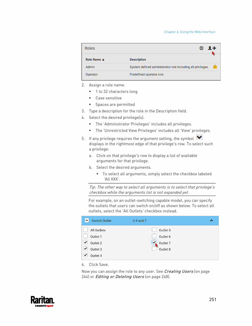
Chapter 6: Using the Web Interface
251
2. Assign a role name.
1 to 32 characters long Case sensitive Spaces are permitted
3. Type a description for the role in the Description field. 4. Select the desired privilege(s).
The 'Administrator Privileges' includes all privileges. The 'Unrestricted View Privileges' includes all 'View' privileges.
5. If any privilege requires the argument setting, the symbol displays in the rightmost edge of that privilege's row. To select such a privilege: a. Click on that privilege's row to display a list of available
arguments for that privilege. b. Select the desired arguments.
To select all arguments, simply select the checkbox labeled 'All XXX'.
Tip: The other way to select all arguments is to select that privilege's checkbox while the arguments list is not expanded yet.
For example, on an outlet-switching capable model, you can specify the outlets that users can switch on/off as shown below. To select all outlets, select the 'All Outlets' checkbox instead.
6. Click Save.
Now you can assign the role to any user. See Creating Users (on page 244) or Editing or Deleting Users (on page 248).
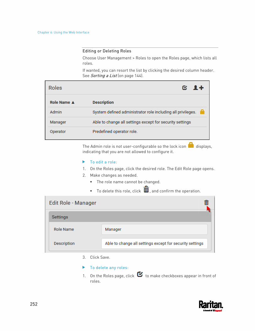
Chapter 6: Using the Web Interface
252
Editing or Deleting Roles
Choose User Management > Roles to open the Roles page, which lists all roles.
If wanted, you can resort the list by clicking the desired column header. See Sorting a List (on page 144).
The Admin role is not user-configurable so the lock icon displays, indicating that you are not allowed to configure it.
To edit a role: 1. On the Roles page, click the desired role. The Edit Role page opens. 2. Make changes as needed.
The role name cannot be changed.
To delete this role, click , and confirm the operation.
3. Click Save.
To delete any roles:
1. On the Roles page, click to make checkboxes appear in front of roles.
Chapter 6: Using the Web Interface
253
Tip: To delete only one role, you can simply click that role without making the checkboxes appear. Refer to the above procedure.
2. Select one or multiple roles. To select all roles, except for the Admin role, select the topmost
checkbox in the header row.
3. Click on the top-right corner. 4. Click Delete on the confirmation message.
Setting Your Preferred Measurement Units
You can change the measurement units shown in the PX3 user interface according to your own preferences regardless of the permissions you have.
Tip: Preferences can also be changed by administrators for specific users on the Edit User page. See Editing or Deleting Users (on page 248).
Measurement unit changes only apply to the web interface and command line interface.
Setting your own preferences does not change the default measurement units. See Setting Default Measurement Units (on page 253).
To select the measurement units you prefer: 1. Choose User Management > User Preferences. 2. Make changes as needed.
Field Description
Temperature Unit Preferred units for temperatures -- (Celsius) or (Fahrenheit).
Length Unit Preferred units for length or height -- Meter or Feet.
Pressure Unit Preferred units for pressure -- Pascal or Psi. Pascal = one newton per square meter Psi = pounds per square inch
3. Click Save.
Setting Default Measurement Units
Default measurement units are applied to all PX3 user interfaces across all users, including users accessing the PX3 via external authentication servers.
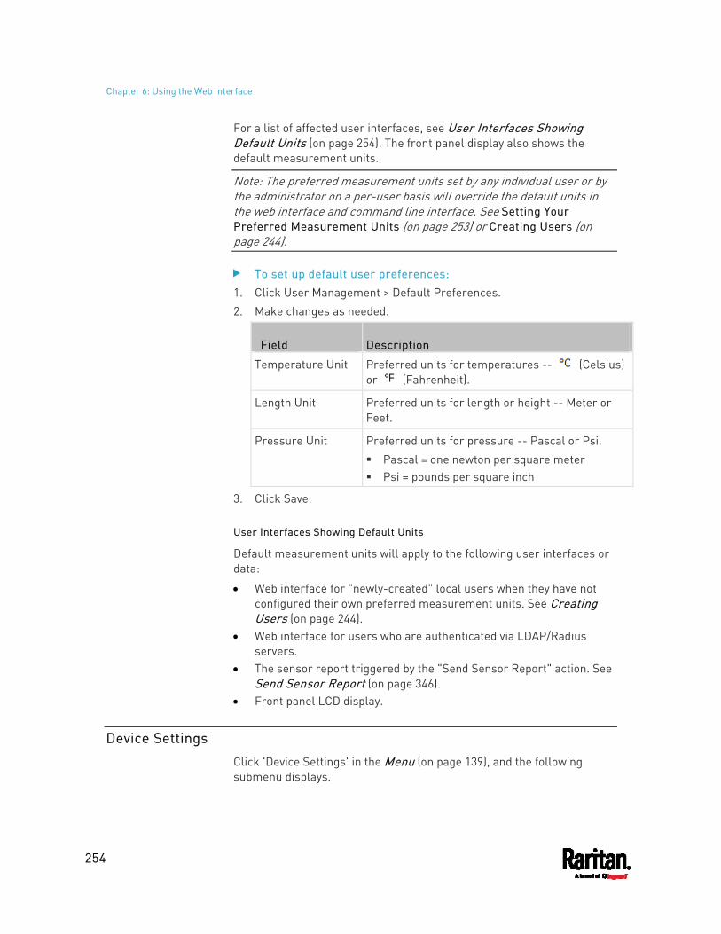
Chapter 6: Using the Web Interface
254
For a list of affected user interfaces, see User Interfaces Showing Default Units (on page 254). The front panel display also shows the default measurement units.
Note: The preferred measurement units set by any individual user or by the administrator on a per-user basis will override the default units in the web interface and command line interface. See Setting Your Preferred Measurement Units (on page 253) or Creating Users (on page 244).
To set up default user preferences: 1. Click User Management > Default Preferences. 2. Make changes as needed.
Field Description
Temperature Unit Preferred units for temperatures -- (Celsius) or (Fahrenheit).
Length Unit Preferred units for length or height -- Meter or Feet.
Pressure Unit Preferred units for pressure -- Pascal or Psi. Pascal = one newton per square meter Psi = pounds per square inch
3. Click Save.
User Interfaces Showing Default Units
Default measurement units will apply to the following user interfaces or data:
Web interface for "newly-created" local users when they have not configured their own preferred measurement units. See Creating Users (on page 244).
Web interface for users who are authenticated via LDAP/Radius servers.
The sensor report triggered by the "Send Sensor Report" action. See Send Sensor Report (on page 346).
Front panel LCD display.
Device Settings
Click 'Device Settings' in the Menu (on page 139), and the following submenu displays.
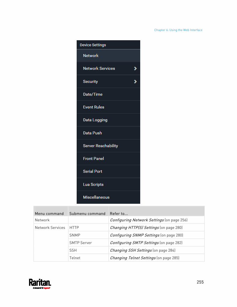
Chapter 6: Using the Web Interface
255
Menu command Submenu command Refer to...
Network Configuring Network Settings (on page 256)
HTTP Changing HTTP(S) Settings (on page 280)
SNMP Configuring SNMP Settings (on page 280)
SMTP Server Configuring SMTP Settings (on page 282)
SSH Changing SSH Settings (on page 284)
Network Services
Telnet Changing Telnet Settings (on page 285)
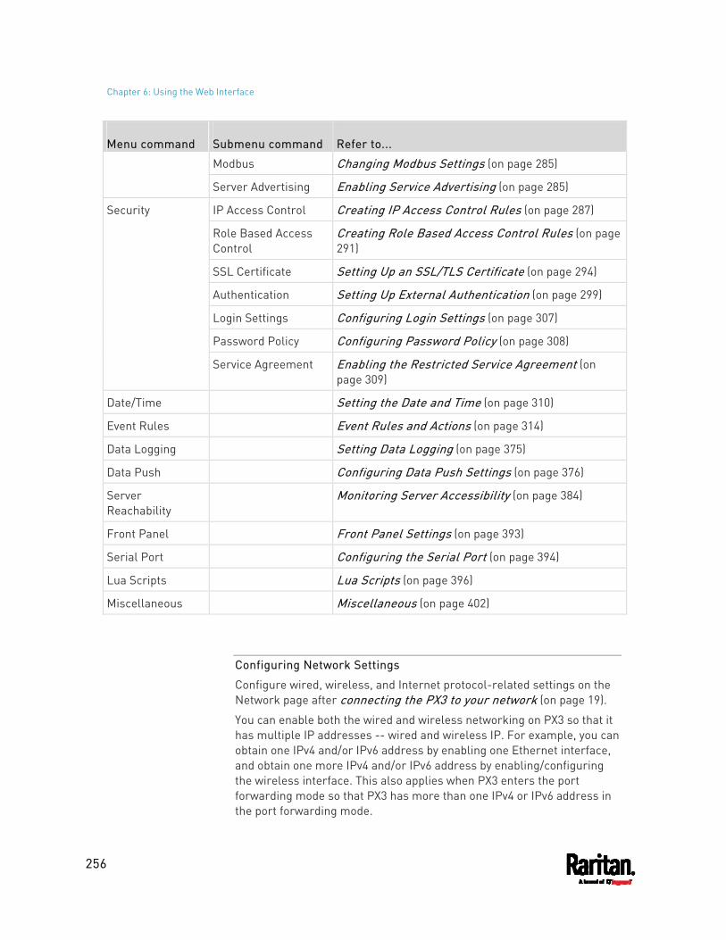
Chapter 6: Using the Web Interface
256
Menu command Submenu command Refer to...
Modbus Changing Modbus Settings (on page 285)
Server Advertising Enabling Service Advertising (on page 285)
IP Access Control Creating IP Access Control Rules (on page 287)
Role Based Access Control
Creating Role Based Access Control Rules (on page 291)
SSL Certificate Setting Up an SSL/TLS Certificate (on page 294)
Authentication Setting Up External Authentication (on page 299)
Login Settings Configuring Login Settings (on page 307)
Password Policy Configuring Password Policy (on page 308)
Security
Service Agreement Enabling the Restricted Service Agreement (on page 309)
Date/Time Setting the Date and Time (on page 310)
Event Rules Event Rules and Actions (on page 314)
Data Logging Setting Data Logging (on page 375)
Data Push Configuring Data Push Settings (on page 376)
Server Reachability
Monitoring Server Accessibility (on page 384)
Front Panel Front Panel Settings (on page 393)
Serial Port Configuring the Serial Port (on page 394)
Lua Scripts Lua Scripts (on page 396)
Miscellaneous Miscellaneous (on page 402)
Configuring Network Settings
Configure wired, wireless, and Internet protocol-related settings on the Network page after connecting the PX3 to your network (on page 19).
You can enable both the wired and wireless networking on PX3 so that it has multiple IP addresses -- wired and wireless IP. For example, you can obtain one IPv4 and/or IPv6 address by enabling one Ethernet interface, and obtain one more IPv4 and/or IPv6 address by enabling/configuring the wireless interface. This also applies when PX3 enters the port forwarding mode so that PX3 has more than one IPv4 or IPv6 address in the port forwarding mode.

Chapter 6: Using the Web Interface
257
However, PX3 in the BRIDGING mode obtains "only one" IP address for wired networking. Wireless networking is NOT supported in this mode.
Important: In the bridging mode, only the IP parameters of the BRIDGE interface function. The IP parameters of ETH1/ETH2 and WIRELESS interfaces do NOT function.
To set up the network settings: 1. Choose Device Settings > Network. 2. To use DHCP-assigned DNS servers and gateway instead of static
ones, go to step 3. To manually specify DNS servers and default gateway, configure the Common Network Settings section. See Common Network Settings (on page 259). Static routes and cascading mode are also in this section. You
need to configure them only when there are such local requirements. See Setting the Cascading Mode (on page 269) and Static Route Examples (on page 265).
3. To configure IPv4/IPv6 settings for a wired network, click the ETH1/ETH2 or BRIDGE section. See Wired Network Settings (on page 258). If the device's cascading mode is set to 'Bridging', the BRIDGE
section appears. Then you must click the BRIDGE section for IPv4/IPv6 settings.
4. To configure IPv4/IPv6 settings for a wireless network, click the WIRELESS section. See Wireless Network Settings (on page 261). You must connect a USB wireless LAN adapter to the PX3 for
wireless networking.
Note: If the device's cascading mode is set to 'Bridging' or its role is set to 'Slave' in the port forwarding mode, the wireless settings will be disabled.
5. To configure the ETH1/ETH2 interface settings, see Ethernet Interface Settings (on page 260).
6. Click Save.
After enabling either or both Internet protocols:
After enabling IPv4 and/or IPv6, all but not limited to the following protocols will be compliant with the selected Internet protocol(s):
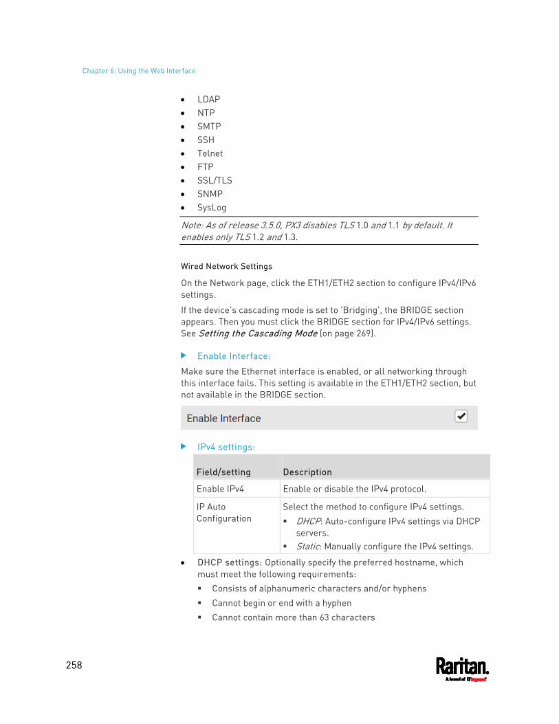
Chapter 6: Using the Web Interface
258
LDAP NTP SMTP SSH Telnet FTP SSL/TLS SNMP SysLog
Note: As of release 3.5.0, PX3 disables TLS 1.0 and 1.1 by default. It enables only TLS 1.2 and 1.3.
Wired Network Settings
On the Network page, click the ETH1/ETH2 section to configure IPv4/IPv6 settings.
If the device's cascading mode is set to 'Bridging', the BRIDGE section appears. Then you must click the BRIDGE section for IPv4/IPv6 settings. See Setting the Cascading Mode (on page 269).
Enable Interface:
Make sure the Ethernet interface is enabled, or all networking through this interface fails. This setting is available in the ETH1/ETH2 section, but not available in the BRIDGE section.
IPv4 settings:
Field/setting Description
Enable IPv4 Enable or disable the IPv4 protocol.
IP Auto Configuration
Select the method to configure IPv4 settings. DHCP: Auto-configure IPv4 settings via DHCP
servers. Static: Manually configure the IPv4 settings.
DHCP settings: Optionally specify the preferred hostname, which must meet the following requirements: Consists of alphanumeric characters and/or hyphens Cannot begin or end with a hyphen Cannot contain more than 63 characters
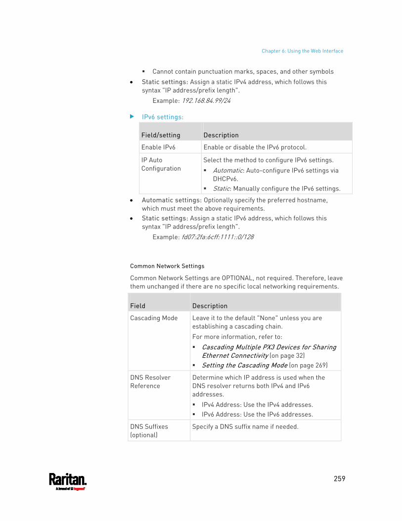
Chapter 6: Using the Web Interface
259
Cannot contain punctuation marks, spaces, and other symbols Static settings: Assign a static IPv4 address, which follows this
syntax "IP address/prefix length". Example: 192.168.84.99/24
IPv6 settings:
Field/setting Description
Enable IPv6 Enable or disable the IPv6 protocol.
IP Auto Configuration
Select the method to configure IPv6 settings. Automatic: Auto-configure IPv6 settings via
DHCPv6. Static: Manually configure the IPv6 settings.
Automatic settings: Optionally specify the preferred hostname, which must meet the above requirements.
Static settings: Assign a static IPv6 address, which follows this syntax "IP address/prefix length".
Example: fd07:2fa:6cff:1111::0/128
Common Network Settings
Common Network Settings are OPTIONAL, not required. Therefore, leave them unchanged if there are no specific local networking requirements.
Field Description
Cascading Mode Leave it to the default "None" unless you are establishing a cascading chain. For more information, refer to: Cascading Multiple PX3 Devices for Sharing
Ethernet Connectivity (on page 32) Setting the Cascading Mode (on page 269)
DNS Resolver Reference
Determine which IP address is used when the DNS resolver returns both IPv4 and IPv6 addresses. IPv4 Address: Use the IPv4 addresses. IPv6 Address: Use the IPv6 addresses.
DNS Suffixes (optional)
Specify a DNS suffix name if needed.
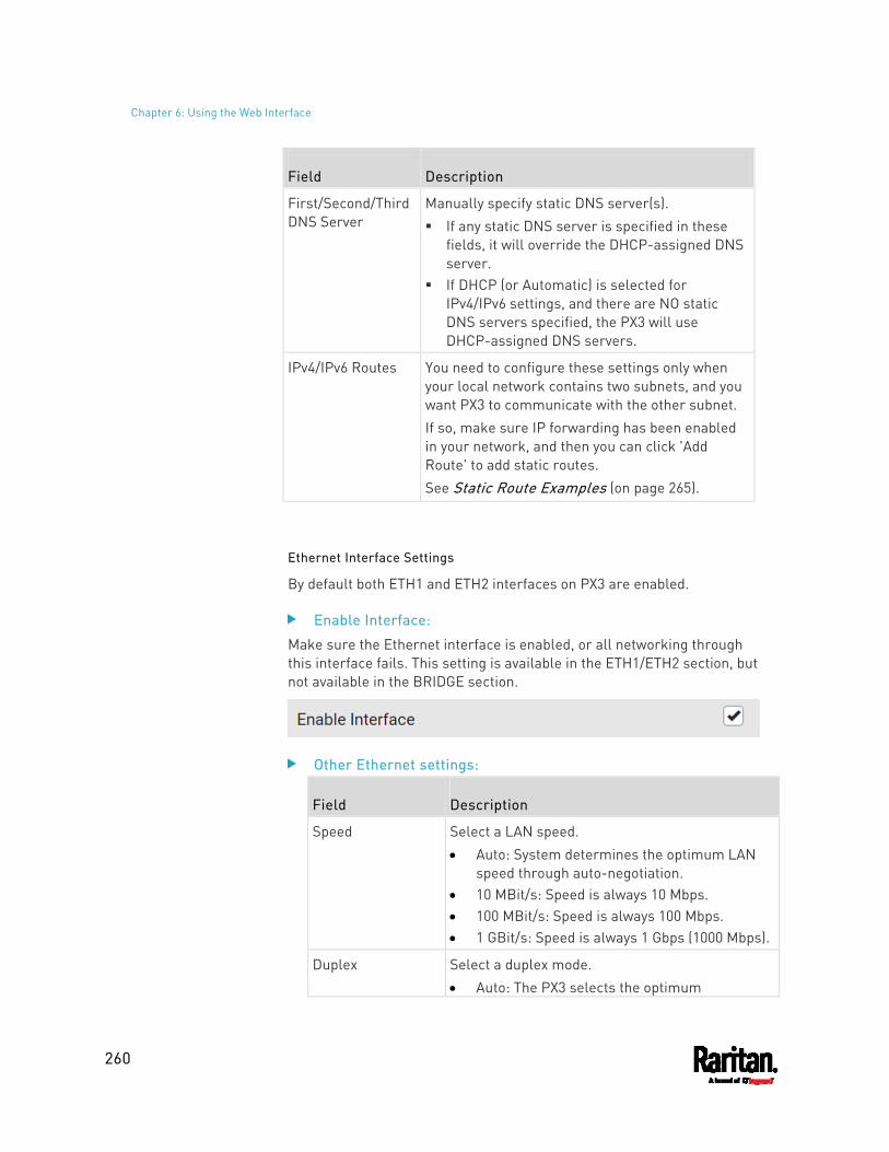
Chapter 6: Using the Web Interface
260
Field Description
First/Second/Third DNS Server
Manually specify static DNS server(s). If any static DNS server is specified in these
fields, it will override the DHCP-assigned DNS server.
If DHCP (or Automatic) is selected for IPv4/IPv6 settings, and there are NO static DNS servers specified, the PX3 will use DHCP-assigned DNS servers.
IPv4/IPv6 Routes You need to configure these settings only when your local network contains two subnets, and you want PX3 to communicate with the other subnet. If so, make sure IP forwarding has been enabled in your network, and then you can click 'Add Route' to add static routes. See Static Route Examples (on page 265).
Ethernet Interface Settings
By default both ETH1 and ETH2 interfaces on PX3 are enabled.
Enable Interface:
Make sure the Ethernet interface is enabled, or all networking through this interface fails. This setting is available in the ETH1/ETH2 section, but not available in the BRIDGE section.
Other Ethernet settings:
Field Description
Speed Select a LAN speed. Auto: System determines the optimum LAN
speed through auto-negotiation. 10 MBit/s: Speed is always 10 Mbps. 100 MBit/s: Speed is always 100 Mbps. 1 GBit/s: Speed is always 1 Gbps (1000 Mbps).
Duplex Select a duplex mode. Auto: The PX3 selects the optimum
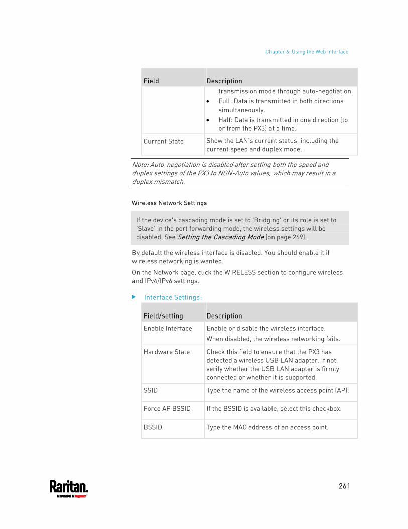
Chapter 6: Using the Web Interface
261
Field Description transmission mode through auto-negotiation.
Full: Data is transmitted in both directions simultaneously.
Half: Data is transmitted in one direction (to or from the PX3) at a time.
Current State Show the LAN's current status, including the current speed and duplex mode.
Note: Auto-negotiation is disabled after setting both the speed and duplex settings of the PX3 to NON-Auto values, which may result in a duplex mismatch.
Wireless Network Settings
If the device's cascading mode is set to 'Bridging' or its role is set to 'Slave' in the port forwarding mode, the wireless settings will be disabled. See Setting the Cascading Mode (on page 269).
By default the wireless interface is disabled. You should enable it if wireless networking is wanted.
On the Network page, click the WIRELESS section to configure wireless and IPv4/IPv6 settings.
Interface Settings:
Field/setting Description
Enable Interface Enable or disable the wireless interface. When disabled, the wireless networking fails.
Hardware State Check this field to ensure that the PX3 has detected a wireless USB LAN adapter. If not, verify whether the USB LAN adapter is firmly connected or whether it is supported.
SSID Type the name of the wireless access point (AP).
Force AP BSSID If the BSSID is available, select this checkbox.
BSSID Type the MAC address of an access point.
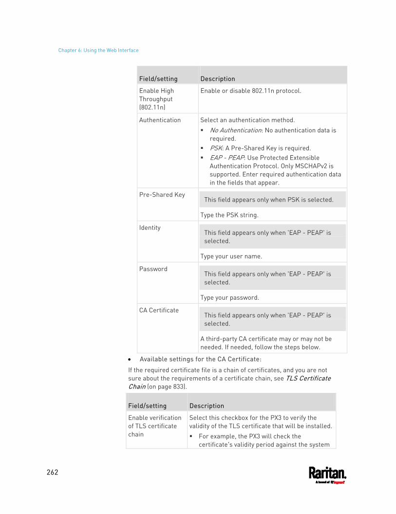
Chapter 6: Using the Web Interface
262
Field/setting Description
Enable High Throughput (802.11n)
Enable or disable 802.11n protocol.
Authentication Select an authentication method. No Authentication: No authentication data is
required. PSK: A Pre-Shared Key is required. EAP - PEAP: Use Protected Extensible
Authentication Protocol. Only MSCHAPv2 is supported. Enter required authentication data in the fields that appear.
Pre-Shared Key This field appears only when PSK is selected.
Type the PSK string.
Identity This field appears only when 'EAP - PEAP' is selected.
Type your user name.
Password This field appears only when 'EAP - PEAP' is selected.
Type your password.
CA Certificate This field appears only when 'EAP - PEAP' is selected.
A third-party CA certificate may or may not be needed. If needed, follow the steps below.
Available settings for the CA Certificate:
If the required certificate file is a chain of certificates, and you are not sure about the requirements of a certificate chain, see TLS Certificate Chain (on page 833).
Field/setting Description
Enable verification of TLS certificate chain
Select this checkbox for the PX3 to verify the validity of the TLS certificate that will be installed. For example, the PX3 will check the
certificate's validity period against the system
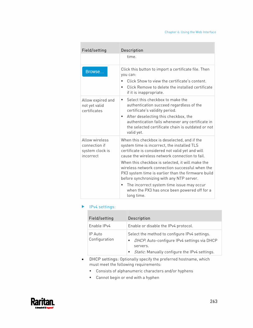
Chapter 6: Using the Web Interface
263
Field/setting Description time.
Click this button to import a certificate file. Then you can: Click Show to view the certificate's content. Click Remove to delete the installed certificate
if it is inappropriate.
Allow expired and not yet valid certificates
Select this checkbox to make the authentication succeed regardless of the certificate's validity period.
After deselecting this checkbox, the authentication fails whenever any certificate in the selected certificate chain is outdated or not valid yet.
Allow wireless connection if system clock is incorrect
When this checkbox is deselected, and if the system time is incorrect, the installed TLS certificate is considered not valid yet and will cause the wireless network connection to fail. When this checkbox is selected, it will make the wireless network connection successful when the PX3 system time is earlier than the firmware build before synchronizing with any NTP server. The incorrect system time issue may occur
when the PX3 has once been powered off for a long time.
IPv4 settings:
Field/setting Description
Enable IPv4 Enable or disable the IPv4 protocol.
IP Auto Configuration
Select the method to configure IPv4 settings. DHCP: Auto-configure IPv4 settings via DHCP
servers. Static: Manually configure the IPv4 settings.
DHCP settings: Optionally specify the preferred hostname, which must meet the following requirements: Consists of alphanumeric characters and/or hyphens Cannot begin or end with a hyphen
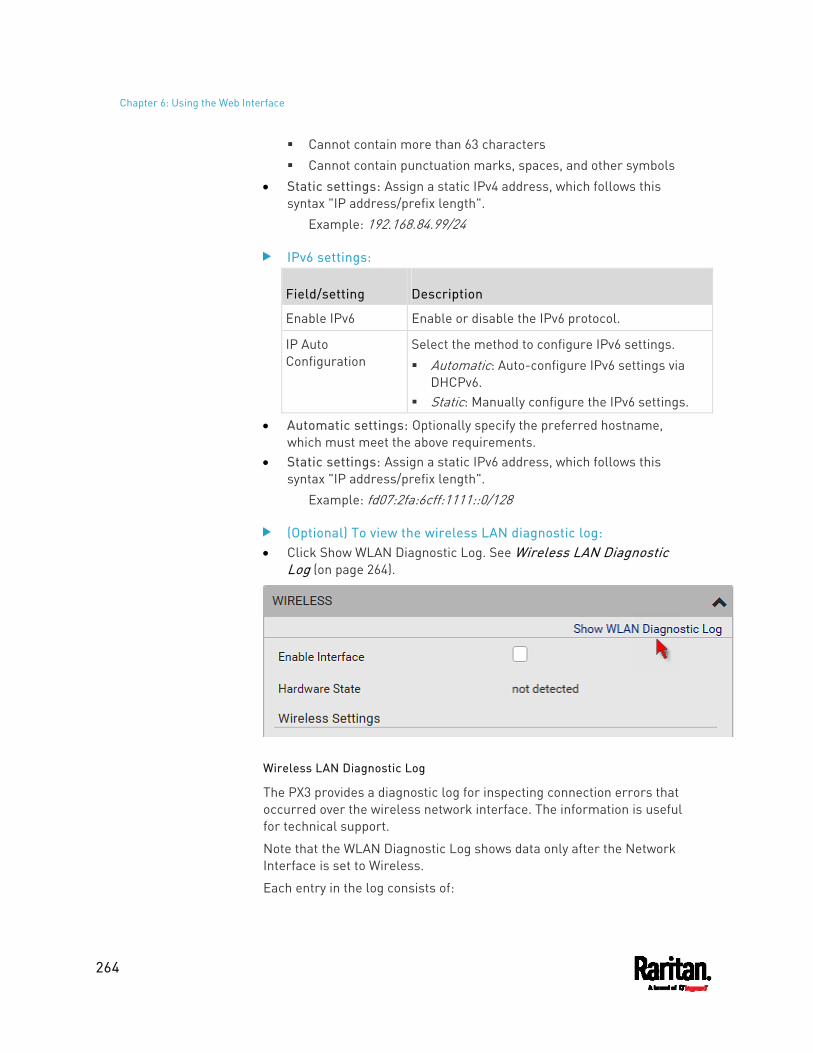
Chapter 6: Using the Web Interface
264
Cannot contain more than 63 characters Cannot contain punctuation marks, spaces, and other symbols
Static settings: Assign a static IPv4 address, which follows this syntax "IP address/prefix length".
Example: 192.168.84.99/24
IPv6 settings:
Field/setting Description
Enable IPv6 Enable or disable the IPv6 protocol.
IP Auto Configuration
Select the method to configure IPv6 settings. Automatic: Auto-configure IPv6 settings via
DHCPv6. Static: Manually configure the IPv6 settings.
Automatic settings: Optionally specify the preferred hostname, which must meet the above requirements.
Static settings: Assign a static IPv6 address, which follows this syntax "IP address/prefix length".
Example: fd07:2fa:6cff:1111::0/128
(Optional) To view the wireless LAN diagnostic log: Click Show WLAN Diagnostic Log. See Wireless LAN Diagnostic
Log (on page 264).
Wireless LAN Diagnostic Log
The PX3 provides a diagnostic log for inspecting connection errors that occurred over the wireless network interface. The information is useful for technical support.
Note that the WLAN Diagnostic Log shows data only after the Network Interface is set to Wireless.
Each entry in the log consists of:
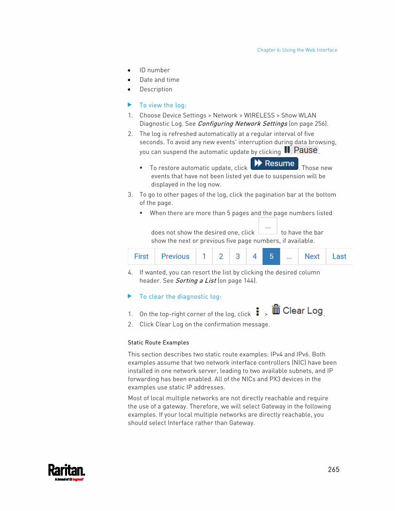
Chapter 6: Using the Web Interface
265
ID number Date and time Description
To view the log: 1. Choose Device Settings > Network > WIRELESS > Show WLAN
Diagnostic Log. See Configuring Network Settings (on page 256). 2. The log is refreshed automatically at a regular interval of five
seconds. To avoid any new events' interruption during data browsing, you can suspend the automatic update by clicking .
To restore automatic update, click . Those new events that have not been listed yet due to suspension will be displayed in the log now.
3. To go to other pages of the log, click the pagination bar at the bottom of the page. When there are more than 5 pages and the page numbers listed
does not show the desired one, click to have the bar show the next or previous five page numbers, if available.
4. If wanted, you can resort the list by clicking the desired column
header. See Sorting a List (on page 144).
To clear the diagnostic log:
1. On the top-right corner of the log, click > . 2. Click Clear Log on the confirmation message.
Static Route Examples
This section describes two static route examples: IPv4 and IPv6. Both examples assume that two network interface controllers (NIC) have been installed in one network server, leading to two available subnets, and IP forwarding has been enabled. All of the NICs and PX3 devices in the examples use static IP addresses.
Most of local multiple networks are not directly reachable and require the use of a gateway. Therefore, we will select Gateway in the following examples. If your local multiple networks are directly reachable, you should select Interface rather than Gateway.
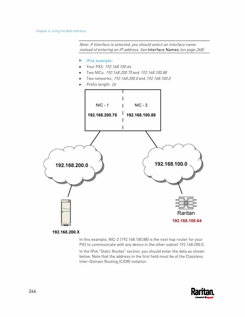
Chapter 6: Using the Web Interface
266
Note: If Interface is selected, you should select an interface name instead of entering an IP address. See Interface Names (on page 268).
IPv4 example: Your PX3: 192.168.100.64 Two NICs: 192.168.200.75 and 192.168.100.88 Two networks: 192.168.200.0 and 192.168.100.0 Prefix length: 24
In this example, NIC-2 (192.168.100.88) is the next hop router for your PX3 to communicate with any device in the other subnet 192.168.200.0.
In the IPv4 "Static Routes" section, you should enter the data as shown below. Note that the address in the first field must be of the Classless Inter-Domain Routing (CIDR) notation.
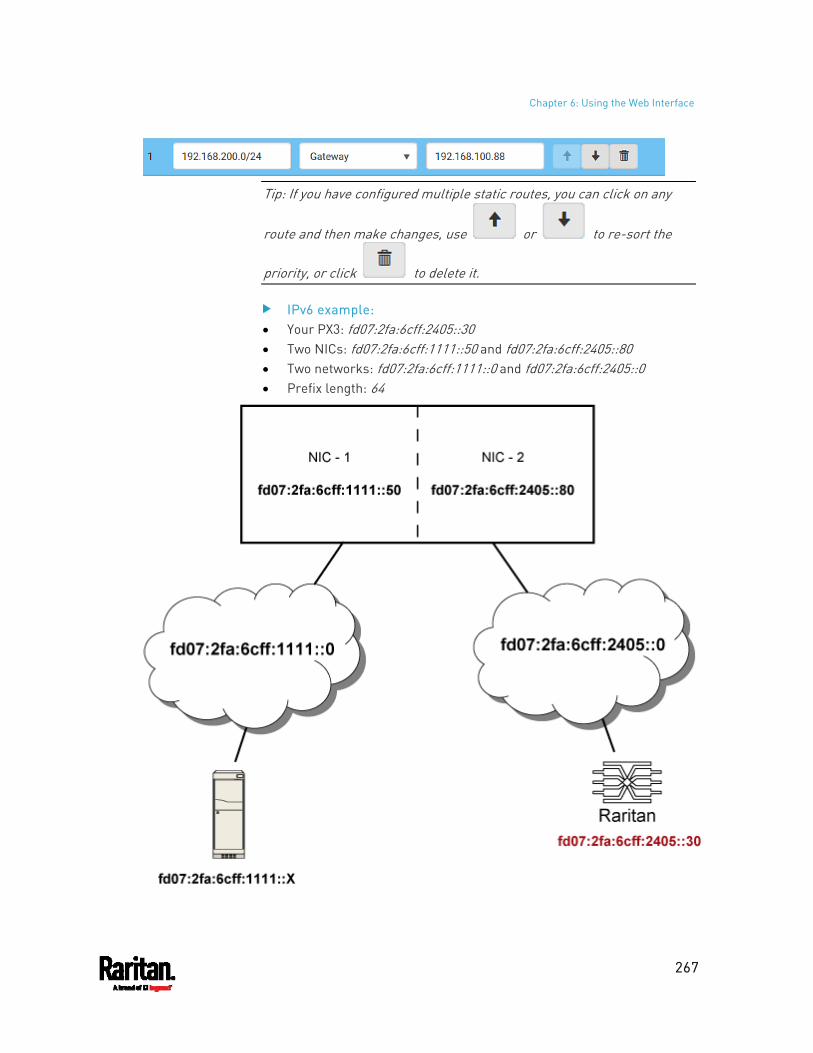
Chapter 6: Using the Web Interface
267
Tip: If you have configured multiple static routes, you can click on any
route and then make changes, use or to re-sort the
priority, or click to delete it.
IPv6 example: Your PX3: fd07:2fa:6cff:2405::30 Two NICs: fd07:2fa:6cff:1111::50 and fd07:2fa:6cff:2405::80 Two networks: fd07:2fa:6cff:1111::0 and fd07:2fa:6cff:2405::0 Prefix length: 64
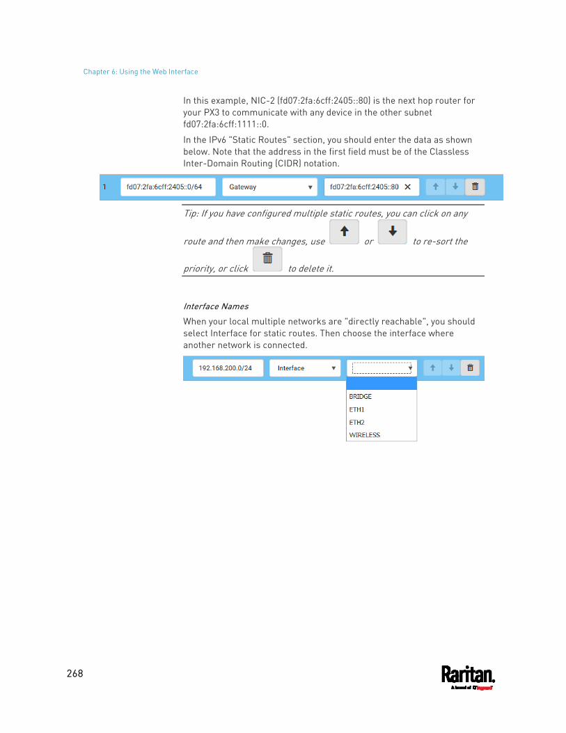
Chapter 6: Using the Web Interface
268
In this example, NIC-2 (fd07:2fa:6cff:2405::80) is the next hop router for your PX3 to communicate with any device in the other subnet fd07:2fa:6cff:1111::0.
In the IPv6 "Static Routes" section, you should enter the data as shown below. Note that the address in the first field must be of the Classless Inter-Domain Routing (CIDR) notation.
Tip: If you have configured multiple static routes, you can click on any
route and then make changes, use or to re-sort the
priority, or click to delete it.
Interface Names
When your local multiple networks are "directly reachable", you should select Interface for static routes. Then choose the interface where another network is connected.
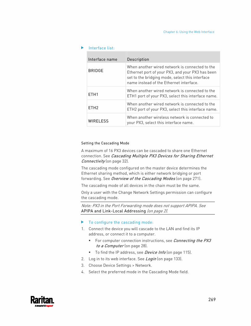
Chapter 6: Using the Web Interface
269
Interface list:
Interface name Description
BRIDGE When another wired network is connected to the Ethernet port of your PX3, and your PX3 has been set to the bridging mode, select this interface name instead of the Ethernet interface.
ETH1 When another wired network is connected to the ETH1 port of your PX3, select this interface name.
ETH2 When another wired network is connected to the ETH2 port of your PX3, select this interface name.
WIRELESS When another wireless network is connected to your PX3, select this interface name.
Setting the Cascading Mode
A maximum of 16 PX3 devices can be cascaded to share one Ethernet connection. See Cascading Multiple PX3 Devices for Sharing Ethernet Connectivity (on page 32).
The cascading mode configured on the master device determines the Ethernet sharing method, which is either network bridging or port forwarding. See Overview of the Cascading Modes (on page 271).
The cascading mode of all devices in the chain must be the same.
Only a user with the Change Network Settings permission can configure the cascading mode.
Note: PX3 in the Port Forwarding mode does not support APIPA. See APIPA and Link-Local Addressing (on page 2).
To configure the cascading mode: 1. Connect the device you will cascade to the LAN and find its IP
address, or connect it to a computer. For computer connection instructions, see Connecting the PX3
to a Computer (on page 28). To find the IP address, see Device Info (on page 115).
2. Log in to its web interface. See Login (on page 133). 3. Choose Device Settings > Network. 4. Select the preferred mode in the Cascading Mode field.
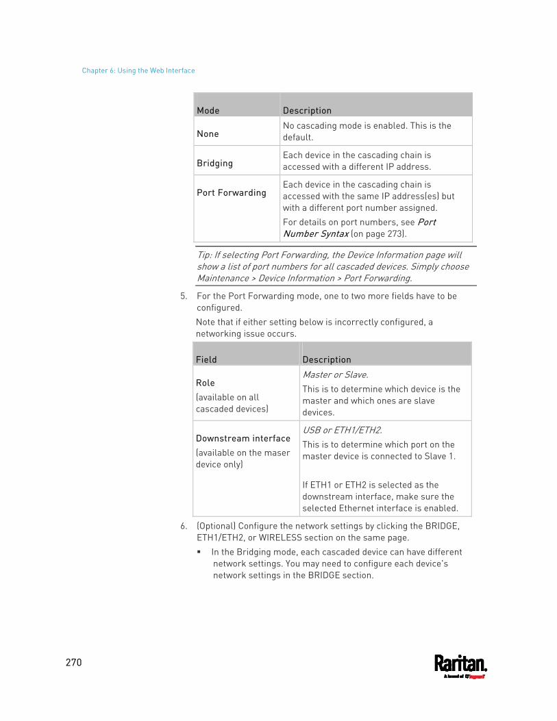
Chapter 6: Using the Web Interface
270
Mode Description
None No cascading mode is enabled. This is the default.
Bridging Each device in the cascading chain is accessed with a different IP address.
Port Forwarding Each device in the cascading chain is accessed with the same IP address(es) but with a different port number assigned. For details on port numbers, see Port Number Syntax (on page 273).
Tip: If selecting Port Forwarding, the Device Information page will show a list of port numbers for all cascaded devices. Simply choose Maintenance > Device Information > Port Forwarding.
5. For the Port Forwarding mode, one to two more fields have to be configured. Note that if either setting below is incorrectly configured, a networking issue occurs.
Field Description
Role (available on all cascaded devices)
Master or Slave. This is to determine which device is the master and which ones are slave devices.
Downstream interface (available on the maser device only)
USB or ETH1/ETH2. This is to determine which port on the master device is connected to Slave 1. If ETH1 or ETH2 is selected as the downstream interface, make sure the selected Ethernet interface is enabled.
6. (Optional) Configure the network settings by clicking the BRIDGE, ETH1/ETH2, or WIRELESS section on the same page. In the Bridging mode, each cascaded device can have different
network settings. You may need to configure each device's network settings in the BRIDGE section.
Chapter 6: Using the Web Interface
271
In the Port Forwarding mode, all cascaded devices share the master device's network settings. You only need to configure the master device's network settings in the ETH1/ETH2 and/or WIRELESS section.
See Wired Network Settings (on page 258) or Wireless Network Settings (on page 261)
Tip: You can enable/configure multiple network interfaces in the Port Forwarding mode so that the cascading chain has multiple IP addresses.
7. Click Save.
For information on accessing each cascaded device in the Port Forwarding mode, see Port Forwarding Examples (on page 275).
Enable R/STP if a cascade loop is preferred: You can "loop" a cascading chain to create network communication
redundancy (Bridging mode only), but only when your network supports R/STP protocol.
Make sure that your network has R/STP enabled if using a cascade loop (Bridging mode) or else network loops may occur.
Online cascading information:
For detailed information on the cascading configuration and restrictions, refer to the Cascading Guide, which is available from Raritan website's Support page (http://www.raritan.com/support/).
Overview of the Cascading Modes
You must apply a cascading mode to the cascading chain. See Setting the Cascading Mode (on page 269).
There are two cascading modes: Bridging and Port Forwarding.
In the following illustration, it is assumed that users enable the DHCP networking for the cascading chain comprising four devices. In the diagrams, "M" is the master device and "S" is a slave device.
Illustration:
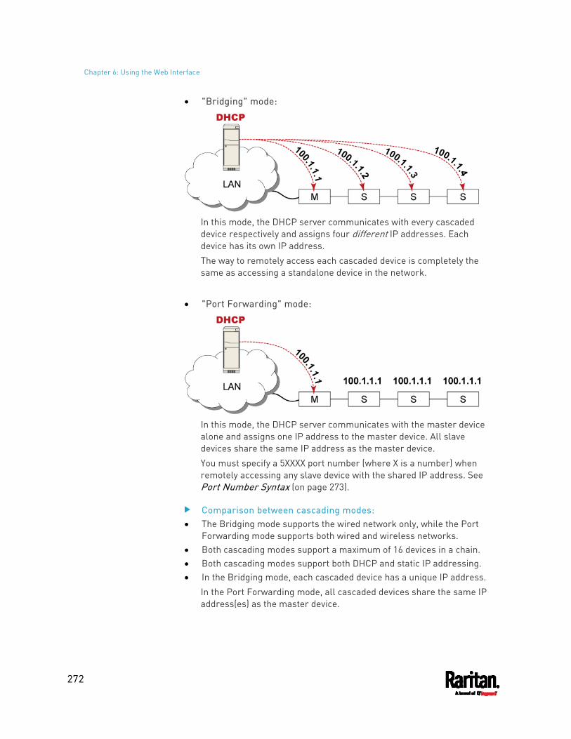
Chapter 6: Using the Web Interface
272
"Bridging" mode:
In this mode, the DHCP server communicates with every cascaded device respectively and assigns four different IP addresses. Each device has its own IP address. The way to remotely access each cascaded device is completely the same as accessing a standalone device in the network.
"Port Forwarding" mode:
In this mode, the DHCP server communicates with the master device alone and assigns one IP address to the master device. All slave devices share the same IP address as the master device. You must specify a 5XXXX port number (where X is a number) when remotely accessing any slave device with the shared IP address. See Port Number Syntax (on page 273).
Comparison between cascading modes: The Bridging mode supports the wired network only, while the Port
Forwarding mode supports both wired and wireless networks. Both cascading modes support a maximum of 16 devices in a chain. Both cascading modes support both DHCP and static IP addressing. In the Bridging mode, each cascaded device has a unique IP address.
In the Port Forwarding mode, all cascaded devices share the same IP address(es) as the master device.
Chapter 6: Using the Web Interface
273
In the Bridging mode, each cascaded device has only one IP address. In the Port Forwarding mode, each cascaded device can have multiple IP addresses as long as the master device has multiple network interfaces enabled/configured properly. For example: When the master device has two Ethernet ports (ETH1/ETH2),
you can enable ETH1, ETH2 and WIRELESS interfaces so that the Port-Forwarding chain has two wired IP addresses and one wireless IP address.
Port Number Syntax
In the Port Forwarding mode, all devices in the cascading chain share the same IP address(es). To access any cascaded device, you must assign an appropriate port number to it.
Master device: The port number is either 5NNXX or the standard TCP/UDP port.
Slave device: The port number is 5NNXX.
5NNXX port number syntax: NN is a two-digit number representing the network protocol as
shown below:
Protocols NN
HTTPS 00
HTTP 01
SSH 02
TELNET 03
SNMP 05
MODBUS 06
Chapter 6: Using the Web Interface
274
XX is a two-digit number representing the device position as shown below.
Position XX Position XX
Master device 00
Slave 8 08
Slave 1 01
Slave 9 09
Slave 2 02
Slave 10 10
Slave 3 03
Slave 11 11
Slave 4 04
Slave 12 12
Slave 5 05
Slave 13 13
Slave 6 06
Slave 14 14
Slave 7 07
Slave 15 15
For example, to access the Slave 4 device via Modbus/TCP, the port number is 50604. See Port Forwarding Examples (on page 275) for further illustrations.
Tip: The full list of each cascaded device's port numbers can be retrieved from the web interface. Choose Maintenance > Device Information > Port Forwarding.
Standard TCP/UDP ports:
The master device can be also accessed through standard TCP/UDP ports as listed in the following table.
Protocols Port Numbers
HTTPS 443
HTTP 80
SSH 22
TELNET 23
SNMP 161
MODBUS 502
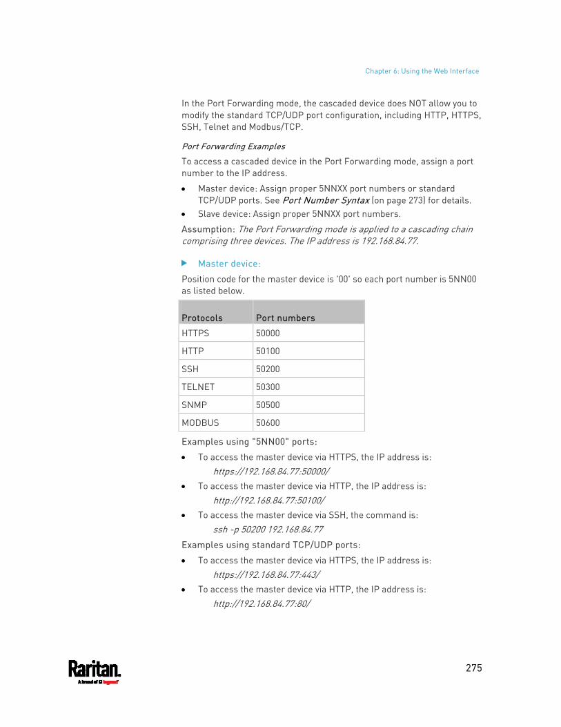
Chapter 6: Using the Web Interface
275
In the Port Forwarding mode, the cascaded device does NOT allow you to modify the standard TCP/UDP port configuration, including HTTP, HTTPS, SSH, Telnet and Modbus/TCP.
Port Forwarding Examples
To access a cascaded device in the Port Forwarding mode, assign a port number to the IP address.
Master device: Assign proper 5NNXX port numbers or standard TCP/UDP ports. See Port Number Syntax (on page 273) for details.
Slave device: Assign proper 5NNXX port numbers.
Assumption: The Port Forwarding mode is applied to a cascading chain comprising three devices. The IP address is 192.168.84.77.
Master device:
Position code for the master device is '00' so each port number is 5NN00 as listed below.
Protocols Port numbers
HTTPS 50000
HTTP 50100
SSH 50200
TELNET 50300
SNMP 50500
MODBUS 50600
Examples using "5NN00" ports:
To access the master device via HTTPS, the IP address is: https://192.168.84.77:50000/
To access the master device via HTTP, the IP address is: http://192.168.84.77:50100/
To access the master device via SSH, the command is: ssh -p 50200 192.168.84.77
Examples using standard TCP/UDP ports:
To access the master device via HTTPS, the IP address is: https://192.168.84.77:443/
To access the master device via HTTP, the IP address is: http://192.168.84.77:80/
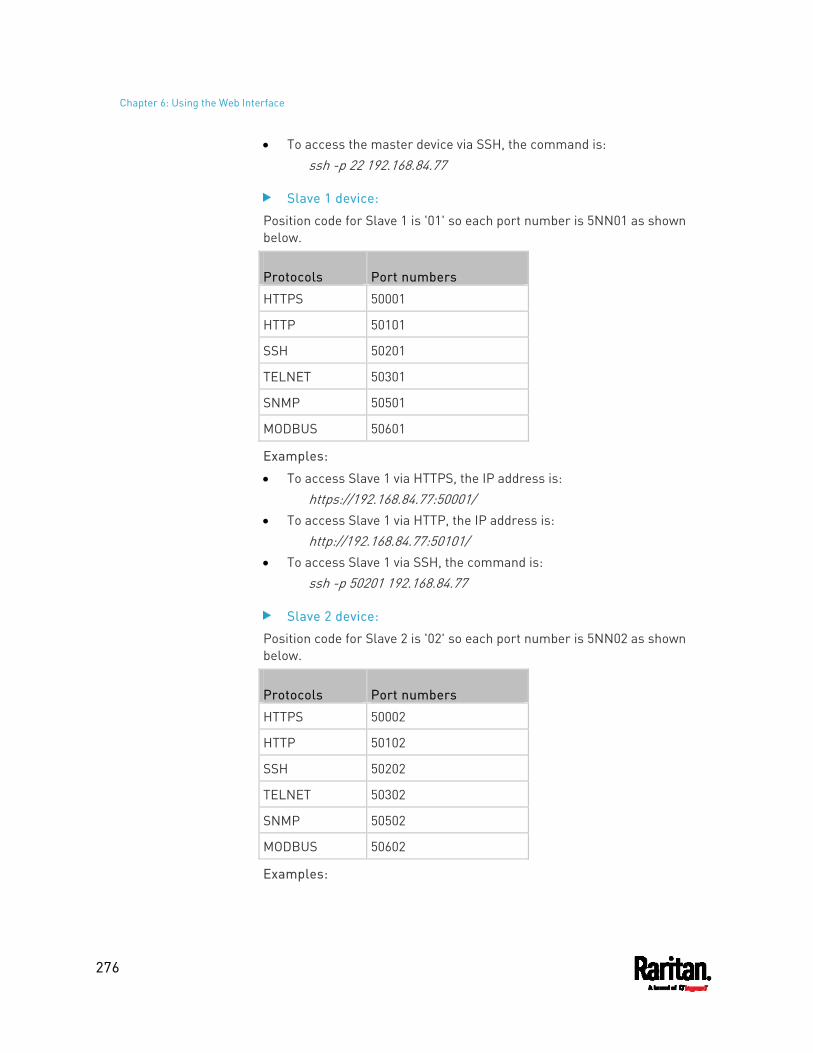
Chapter 6: Using the Web Interface
276
To access the master device via SSH, the command is: ssh -p 22 192.168.84.77
Slave 1 device:
Position code for Slave 1 is '01' so each port number is 5NN01 as shown below.
Protocols Port numbers
HTTPS 50001
HTTP 50101
SSH 50201
TELNET 50301
SNMP 50501
MODBUS 50601
Examples:
To access Slave 1 via HTTPS, the IP address is: https://192.168.84.77:50001/
To access Slave 1 via HTTP, the IP address is: http://192.168.84.77:50101/
To access Slave 1 via SSH, the command is: ssh -p 50201 192.168.84.77
Slave 2 device:
Position code for Slave 2 is '02' so each port number is 5NN02 as shown below.
Protocols Port numbers
HTTPS 50002
HTTP 50102
SSH 50202
TELNET 50302
SNMP 50502
MODBUS 50602
Examples:
Chapter 6: Using the Web Interface
277
To access Slave 2 via HTTPS, the IP address is: https://192.168.84.77:50002/
To access Slave 2 via HTTP, the IP address is: http://192.168.84.77:50102/
To access Slave 2 via SSH, the command is: ssh -p 50202 192.168.84.77
Adding, Removing or Swapping Cascaded Devices
Change a device's cascading mode first before adding that device to a cascading chain, or before disconnecting that device from the chain.
If you only want to change the cascading mode of an existing chain, or swap the master and slave device, always start from the slave device.
Note: If the following procedures are not followed, a networking issue occurs. When a networking issue occurs, check the cascading connection and/or software settings of all devices in the chain. See Cascading Troubleshooting (on page 822).
To add a device to an existing chain: 1. Connect the device you will cascade to the LAN and find its IP
address, or connect it to a computer. 2. Log in to this device and set its cascading mode to be the same as
the existing chain's cascading mode. See Setting the Cascading Mode (on page 269).
3. (Optional) If this device will function as a slave device, disconnect it from the LAN after configuring the cascading mode.
4. Connect this device to the chain, using either a USB or Ethernet cable.
To remove a device from the chain: 1. Log in to the desired cascaded device, and change its cascading
mode to None.
Exception: If you are going to connect the removed device to another cascading chain, set its cascading mode to be the same as the mode of another chain.
2. Now disconnect it from the cascading chain.
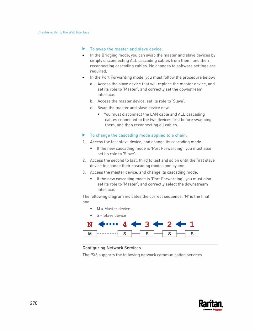
Chapter 6: Using the Web Interface
278
To swap the master and slave device: In the Bridging mode, you can swap the master and slave devices by
simply disconnecting ALL cascading cables from them, and then reconnecting cascading cables. No changes to software settings are required.
In the Port Forwarding mode, you must follow the procedure below: a. Access the slave device that will replace the master device, and
set its role to 'Master', and correctly set the downstream interface.
b. Access the master device, set its role to 'Slave'. c. Swap the master and slave device now.
You must disconnect the LAN cable and ALL cascading cables connected to the two devices first before swapping them, and then reconnecting all cables.
To change the cascading mode applied to a chain: 1. Access the last slave device, and change its cascading mode.
If the new cascading mode is 'Port Forwarding', you must also set its role to 'Slave'.
2. Access the second to last, third to last and so on until the first slave device to change their cascading modes one by one.
3. Access the master device, and change its cascading mode. If the new cascading mode is 'Port Forwarding', you must also
set its role to 'Master', and correctly select the downstream interface.
The following diagram indicates the correct sequence. 'N' is the final one.
M = Master device S = Slave device
Configuring Network Services
The PX3 supports the following network communication services.
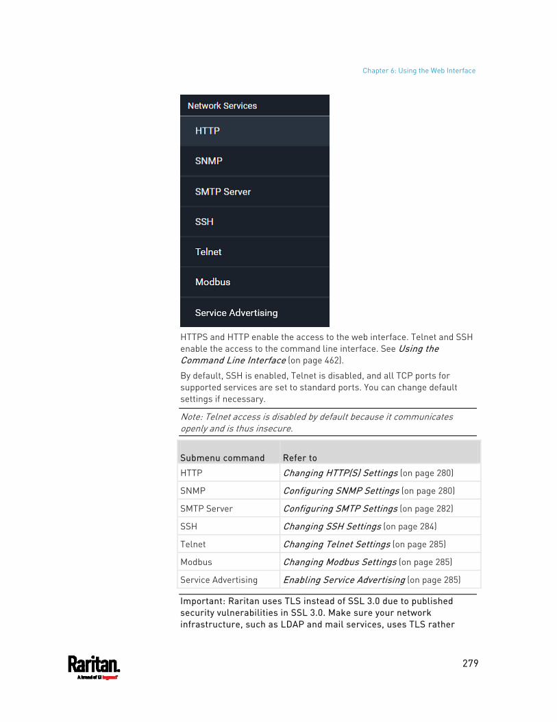
Chapter 6: Using the Web Interface
279
HTTPS and HTTP enable the access to the web interface. Telnet and SSH enable the access to the command line interface. See Using the Command Line Interface (on page 462).
By default, SSH is enabled, Telnet is disabled, and all TCP ports for supported services are set to standard ports. You can change default settings if necessary.
Note: Telnet access is disabled by default because it communicates openly and is thus insecure.
Submenu command Refer to
HTTP Changing HTTP(S) Settings (on page 280)
SNMP Configuring SNMP Settings (on page 280)
SMTP Server Configuring SMTP Settings (on page 282)
SSH Changing SSH Settings (on page 284)
Telnet Changing Telnet Settings (on page 285)
Modbus Changing Modbus Settings (on page 285)
Service Advertising Enabling Service Advertising (on page 285)
Important: Raritan uses TLS instead of SSL 3.0 due to published security vulnerabilities in SSL 3.0. Make sure your network infrastructure, such as LDAP and mail services, uses TLS rather
Chapter 6: Using the Web Interface
280
than SSL 3.0.
Changing HTTP(S) Settings
HTTPS uses Transport Layer Security (TLS) technology to encrypt all traffic to and from the PX3 so it is a more secure protocol than HTTP. As of release 3.5.0, PX3 disables TLS 1.0 and 1.1 by default. It enables only TLS 1.2 and 1.3.
By default, any access to the PX3 via HTTP is automatically redirected to HTTPS. You can disable this redirection if needed.
To change HTTP or HTTPS port settings: 1. Choose Device Settings > Network Services > HTTP. 2. Enable either or both protocols by selecting the corresponding
'Enable' checkbox. 3. To use a different port for HTTP or HTTPS, type a new port number.
Warning: Different network services cannot share the same TCP port.
4. To redirect the HTTP access to the PX3 to HTTPS, select the "Redirect HTTP connections to HTTPS." The redirection checkbox is configurable only when both HTTP
and HTTPS have been enabled.
Special note for AES ciphers:
The PX3 device's SSL/TLS-based protocols, including HTTPS, support AES 128- and 256-bit ciphers. The exact cipher to use is negotiated between PX3 and the client (such as a web browser), which is impacted by the cipher priority of PX3 and the client's cipher availability/settings.
Tip: To force PX3 to use a specific AES cipher, refer to your client's user documentation for information on configuring AES settings. For example, you can enable a cipher and disable the other in the Firefox via the "about:config" command.
Configuring SNMP Settings
You can enable or disable SNMP communication between an SNMP manager and the PX3. Enabling SNMP communication allows the manager to retrieve and even control the power status of each outlet.
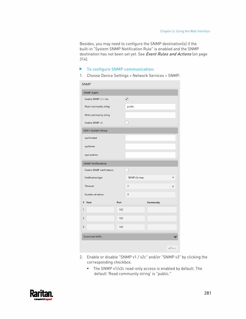
Chapter 6: Using the Web Interface
281
Besides, you may need to configure the SNMP destination(s) if the built-in "System SNMP Notification Rule" is enabled and the SNMP destination has not been set yet. See Event Rules and Actions (on page 314).
To configure SNMP communication: 1. Choose Device Settings > Network Services > SNMP.
2. Enable or disable "SNMP v1 / v2c" and/or "SNMP v3" by clicking the
corresponding checkbox. The SNMP v1/v2c read-only access is enabled by default. The
default 'Read community string' is "public."
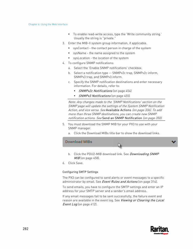
Chapter 6: Using the Web Interface
282
To enable read-write access, type the 'Write community string.' Usually the string is "private."
3. Enter the MIB-II system group information, if applicable. sysContact - the contact person in charge of the system sysName - the name assigned to the system sysLocation - the location of the system
4. To configure SNMP notifications: a. Select the 'Enable SNMP notifications' checkbox. b. Select a notification type -- SNMPv2c trap, SNMPv2c inform,
SNMPv3 trap, and SNMPv3 inform. c. Specify the SNMP notification destinations and enter necessary
information. For details, refer to: SNMPv2c Notifications (on page 454) SNMPv3 Notifications (on page 455)
Note: Any changes made to the 'SNMP Notifications' section on the SNMP page will update the settings of the System SNMP Notification Action, and vice versa. See Available Actions (on page 336). To add more than three SNMP destinations, you can create new SNMP notification actions. See Send an SNMP Notification (on page 350).
5. You must download the SNMP MIB for your PX3 to use with your SNMP manager. a. Click the Download MIBs title bar to show the download links.
b. Click the PDU2-MIB download link. See Downloading SNMP
MIB (on page 458). 6. Click Save.
Configuring SMTP Settings
The PX3 can be configured to send alerts or event messages to a specific administrator by email. See Event Rules and Actions (on page 314).
To send emails, you have to configure the SMTP settings and enter an IP address for your SMTP server and a sender's email address.
If any email messages fail to be sent successfully, the failure event and reason are available in the event log. See Viewing or Clearing the Local Event Log (on page 412).
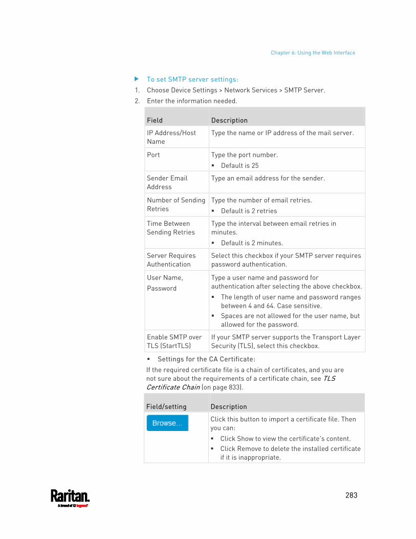
Chapter 6: Using the Web Interface
283
To set SMTP server settings: 1. Choose Device Settings > Network Services > SMTP Server. 2. Enter the information needed.
Field Description
IP Address/Host Name
Type the name or IP address of the mail server.
Port Type the port number. Default is 25
Sender Email Address
Type an email address for the sender.
Number of Sending Retries
Type the number of email retries. Default is 2 retries
Time Between Sending Retries
Type the interval between email retries in minutes. Default is 2 minutes.
Server Requires Authentication
Select this checkbox if your SMTP server requires password authentication.
User Name, Password
Type a user name and password for authentication after selecting the above checkbox. The length of user name and password ranges
between 4 and 64. Case sensitive. Spaces are not allowed for the user name, but
allowed for the password.
Enable SMTP over TLS (StartTLS)
If your SMTP server supports the Transport Layer Security (TLS), select this checkbox.
Settings for the CA Certificate: If the required certificate file is a chain of certificates, and you are not sure about the requirements of a certificate chain, see TLS Certificate Chain (on page 833).
Field/setting Description
Click this button to import a certificate file. Then you can: Click Show to view the certificate's content. Click Remove to delete the installed certificate
if it is inappropriate.
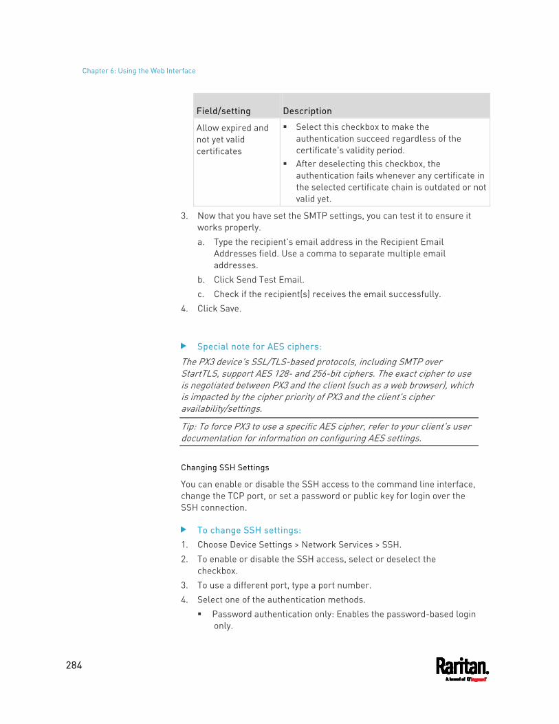
Chapter 6: Using the Web Interface
284
Field/setting Description
Allow expired and not yet valid certificates
Select this checkbox to make the authentication succeed regardless of the certificate's validity period.
After deselecting this checkbox, the authentication fails whenever any certificate in the selected certificate chain is outdated or not valid yet.
3. Now that you have set the SMTP settings, you can test it to ensure it works properly. a. Type the recipient's email address in the Recipient Email
Addresses field. Use a comma to separate multiple email addresses.
b. Click Send Test Email. c. Check if the recipient(s) receives the email successfully.
4. Click Save.
Special note for AES ciphers:
The PX3 device's SSL/TLS-based protocols, including SMTP over StartTLS, support AES 128- and 256-bit ciphers. The exact cipher to use is negotiated between PX3 and the client (such as a web browser), which is impacted by the cipher priority of PX3 and the client's cipher availability/settings.
Tip: To force PX3 to use a specific AES cipher, refer to your client's user documentation for information on configuring AES settings.
Changing SSH Settings
You can enable or disable the SSH access to the command line interface, change the TCP port, or set a password or public key for login over the SSH connection.
To change SSH settings: 1. Choose Device Settings > Network Services > SSH. 2. To enable or disable the SSH access, select or deselect the
checkbox. 3. To use a different port, type a port number. 4. Select one of the authentication methods.
Password authentication only: Enables the password-based login only.
Chapter 6: Using the Web Interface
285
Public key authentication only: Enables the public key-based login only.
Password and public key authentication: Enables both the password- and public key-based login. This is the default.
5. Click Save.
If the public key authentication is selected, you must enter a valid SSH public key for each user profile to log in over the SSH connection. See Creating Users (on page 244).
Changing Telnet Settings
You can enable or disable the Telnet access to the command line interface, or change the TCP port.
To change Telnet settings: 1. Choose Device Settings > Network Services > Telnet. 2. To enable the Telnet access, select the checkbox. 3. To use a different port, type a new port number. 4. Click Save.
Changing Modbus Settings
You can enable or disable the Modbus/TCP access to the PX3, set it to the read-only mode, or change the TCP port.
To change the Modbus/TCP settings: 1. Choose Device Settings > Network Services > Modbus. 2. To enable the Modbus/TCP access, select the "Modbus/TCP Access"
checkbox. 3. To use a different port, type a new port number. 4. To enable the Modbus read-only mode, select the checkbox of the
"Read-only mode" field. To enable the read-write mode, deselect it.
Enabling Service Advertising
The PX3 advertises all enabled services that are reachable using the IP network. This feature uses DNS-SD (Domain Name System-Service Discovery) and MDNS (Multicast DNS). The advertised services are discovered by clients that have implemented DNS-SD and MDNS.
The advertised services include the following:
Chapter 6: Using the Web Interface
286
HTTP HTTPS Telnet SSH Modbus json-rpc SNMP
By default, this feature is enabled.
Enabling this feature also enables Link-Local Multicast Name Resolution (LLMNR) and/or MDNS, which are required for resolving APIPA host names. See APIPA and Link-Local Addressing (on page 2).
The service advertisement feature supports both IPv4 and IPv6 protocols.
If you have set a preferred host name for IPv4 and/or IPv6, that host name can be used as the zero configuration .local host name, that is, <preferred_host_name>.local, where <preferred_host_name> is the preferred host name you have specified for PX3. The IPv4 host name is the first priority. If an IPv4 host name is not available, then use the IPv6 host name.
Note: For information on configuring IPv4 and/or IPv6 network settings, see Wired Network Settings (on page 258).
To enable or disable service advertising: 1. Choose Device Settings > Network Services > Service Advertising. 2. To enable the service advertising, select either or both checkboxes.
To advertise via MDNS, select the Multicast DNS checkbox. To advertise via LLMNR, select the Link-Local Multicast Name
Resolution checkbox. 3. Click Save.
Configuring Security Settings
The PX3 provides tools to control access. You can enable the internal firewall, create firewall rules, and set login limitations. In addition, you can create and install the certificate or set up external authentication servers for access control. This product supports SHA-2 TLS certificates.
Tip: To force all HTTP accesses to the PX3 to be redirected to HTTPS, see Changing HTTP(S) Settings (on page 280).
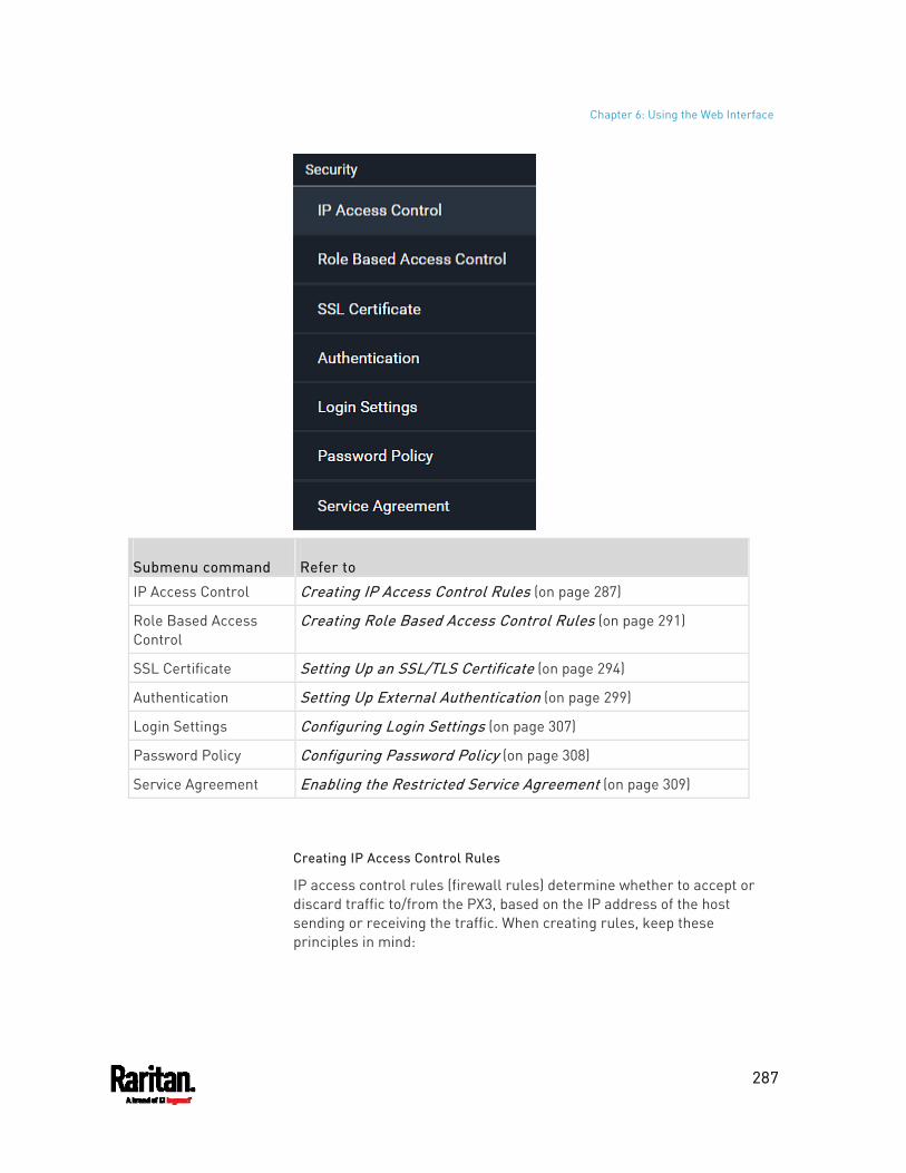
Chapter 6: Using the Web Interface
287
Submenu command Refer to
IP Access Control Creating IP Access Control Rules (on page 287)
Role Based Access Control
Creating Role Based Access Control Rules (on page 291)
SSL Certificate Setting Up an SSL/TLS Certificate (on page 294)
Authentication Setting Up External Authentication (on page 299)
Login Settings Configuring Login Settings (on page 307)
Password Policy Configuring Password Policy (on page 308)
Service Agreement Enabling the Restricted Service Agreement (on page 309)
Creating IP Access Control Rules
IP access control rules (firewall rules) determine whether to accept or discard traffic to/from the PX3, based on the IP address of the host sending or receiving the traffic. When creating rules, keep these principles in mind:
Chapter 6: Using the Web Interface
288
Rule order is important. When traffic reaches or is sent from the PX3, the rules are executed in numerical order. Only the first rule that matches the IP address determines whether the traffic is accepted or discarded. Any subsequent rules matching the IP address are ignored.
Prefix length is required. When typing the IP address, you must specify it in the CIDR notation. That is, BOTH the address and the prefix length are included. For example, to specify a single address with the 24-bit prefix length, use this format: x.x.x.x/24 /24 = the prefix length.
Note: Valid IPv4 addresses range from 0.0.0.0 through 255.255.255.255.
To configure IPv4 access control rules: 1. Choose Device Settings > Security > IP Access Control. 2. Select the 'Enable IPv4 access control' checkbox to enable IPv4
access control rules. 3. Determine the IPv4 default policy.
Accept: Accepts traffic from all IPv4 addresses. Drop: Discards traffic from all IPv4 addresses, without sending
any failure notification to the source host. Reject: Discards traffic from all IPv4 addresses, and an ICMP
message is sent to the source host for failure notification. 4. Go to the Inbound Rules section or the Outbound Rules section
according to your needs. Inbound rules control the data sent to the PX3. Outbound rules control the data sent from the PX3.
5. Create rules. Refer to the tables below for different operations.
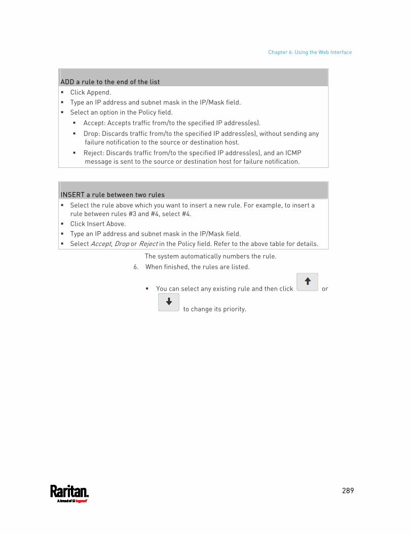
Chapter 6: Using the Web Interface
289
ADD a rule to the end of the list Click Append. Type an IP address and subnet mask in the IP/Mask field. Select an option in the Policy field.
Accept: Accepts traffic from/to the specified IP address(es). Drop: Discards traffic from/to the specified IP address(es), without sending any
failure notification to the source or destination host. Reject: Discards traffic from/to the specified IP address(es), and an ICMP
message is sent to the source or destination host for failure notification.
INSERT a rule between two rules Select the rule above which you want to insert a new rule. For example, to insert a
rule between rules #3 and #4, select #4. Click Insert Above. Type an IP address and subnet mask in the IP/Mask field. Select Accept, Drop or Reject in the Policy field. Refer to the above table for details.
The system automatically numbers the rule. 6. When finished, the rules are listed.
You can select any existing rule and then click or
to change its priority.
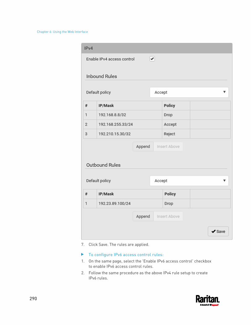
Chapter 6: Using the Web Interface
290
7. Click Save. The rules are applied.
To configure IPv6 access control rules: 1. On the same page, select the 'Enable IPv6 access control' checkbox
to enable IPv6 access control rules. 2. Follow the same procedure as the above IPv4 rule setup to create
IPv6 rules.
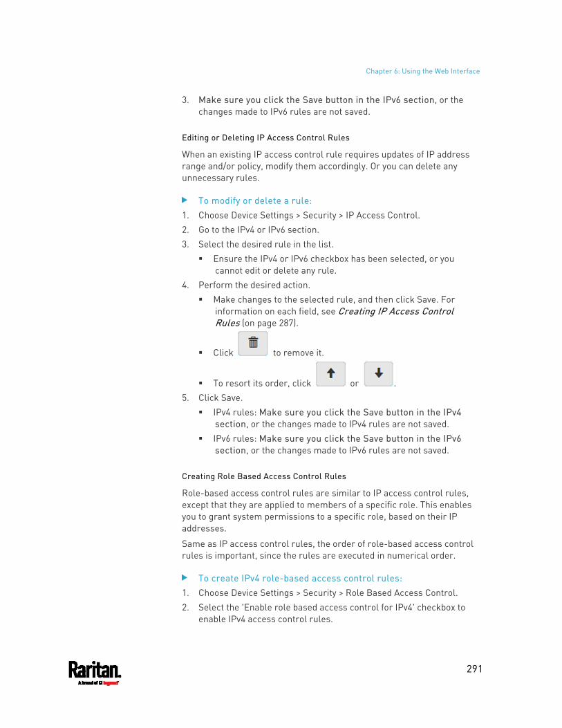
Chapter 6: Using the Web Interface
291
3. Make sure you click the Save button in the IPv6 section, or the changes made to IPv6 rules are not saved.
Editing or Deleting IP Access Control Rules
When an existing IP access control rule requires updates of IP address range and/or policy, modify them accordingly. Or you can delete any unnecessary rules.
To modify or delete a rule: 1. Choose Device Settings > Security > IP Access Control. 2. Go to the IPv4 or IPv6 section. 3. Select the desired rule in the list.
Ensure the IPv4 or IPv6 checkbox has been selected, or you cannot edit or delete any rule.
4. Perform the desired action. Make changes to the selected rule, and then click Save. For
information on each field, see Creating IP Access Control Rules (on page 287).
Click to remove it.
To resort its order, click or . 5. Click Save.
IPv4 rules: Make sure you click the Save button in the IPv4 section, or the changes made to IPv4 rules are not saved.
IPv6 rules: Make sure you click the Save button in the IPv6 section, or the changes made to IPv6 rules are not saved.
Creating Role Based Access Control Rules
Role-based access control rules are similar to IP access control rules, except that they are applied to members of a specific role. This enables you to grant system permissions to a specific role, based on their IP addresses.
Same as IP access control rules, the order of role-based access control rules is important, since the rules are executed in numerical order.
To create IPv4 role-based access control rules: 1. Choose Device Settings > Security > Role Based Access Control. 2. Select the 'Enable role based access control for IPv4' checkbox to
enable IPv4 access control rules.
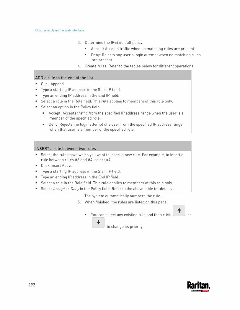
Chapter 6: Using the Web Interface
292
3. Determine the IPv4 default policy. Accept: Accepts traffic when no matching rules are present. Deny: Rejects any user's login attempt when no matching rules
are present. 4. Create rules. Refer to the tables below for different operations.
ADD a rule to the end of the list Click Append. Type a starting IP address in the Start IP field. Type an ending IP address in the End IP field. Select a role in the Role field. This rule applies to members of this role only. Select an option in the Policy field.
Accept: Accepts traffic from the specified IP address range when the user is a member of the specified role.
Deny: Rejects the login attempt of a user from the specified IP address range when that user is a member of the specified role.
INSERT a rule between two rules Select the rule above which you want to insert a new rule. For example, to insert a
rule between rules #3 and #4, select #4. Click Insert Above. Type a starting IP address in the Start IP field. Type an ending IP address in the End IP field. Select a role in the Role field. This rule applies to members of this role only. Select Accept or Deny in the Policy field. Refer to the above table for details.
The system automatically numbers the rule. 5. When finished, the rules are listed on this page.
You can select any existing rule and then click or
to change its priority.
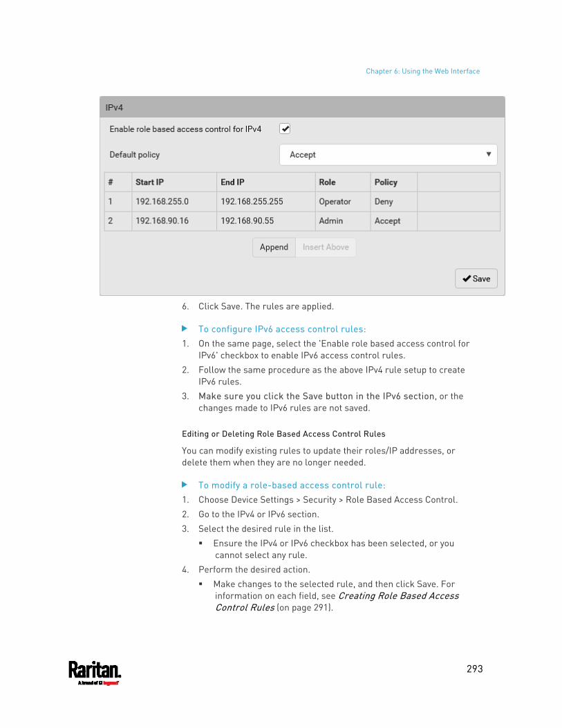
Chapter 6: Using the Web Interface
293
6. Click Save. The rules are applied.
To configure IPv6 access control rules: 1. On the same page, select the 'Enable role based access control for
IPv6' checkbox to enable IPv6 access control rules. 2. Follow the same procedure as the above IPv4 rule setup to create
IPv6 rules. 3. Make sure you click the Save button in the IPv6 section, or the
changes made to IPv6 rules are not saved.
Editing or Deleting Role Based Access Control Rules
You can modify existing rules to update their roles/IP addresses, or delete them when they are no longer needed.
To modify a role-based access control rule: 1. Choose Device Settings > Security > Role Based Access Control. 2. Go to the IPv4 or IPv6 section. 3. Select the desired rule in the list.
Ensure the IPv4 or IPv6 checkbox has been selected, or you cannot select any rule.
4. Perform the desired action. Make changes to the selected rule, and then click Save. For
information on each field, see Creating Role Based Access Control Rules (on page 291).
Chapter 6: Using the Web Interface
294
Click to remove it.
To resort its order, click or . 5. Click Save.
IPv4 rules: Make sure you click the Save button in the IPv4 section, or the changes made to IPv4 rules are not saved.
IPv6 rules: Make sure you click the Save button in the IPv6 section, or the changes made to IPv6 rules are not saved.
Setting Up an SSL/TLS Certificate
Important: Raritan uses TLS instead of SSL 3.0 due to published security vulnerabilities in SSL 3.0. Make sure your network infrastructure, such as LDAP and mail services, uses TLS rather than SSL 3.0.
Having an X.509 digital certificate ensures that both parties in an SSL/TLS connection are who they say they are.
Besides, you can create or apply for a multi-domain certificate with subject alternative names.
To obtain a CA-signed certificate: 1. Create a Certificate Signing Request (CSR) on the PX3. See Creating
a CSR (on page 294). 2. Submit it to a certificate authority (CA). After the CA processes the
information in the CSR, it provides you with a certificate. 3. Import the CA-signed certificate onto the PX3. See Installing a
CA-Signed Certificate (on page 296).
Note: If you are using a certificate that is part of a chain of certificates, each part of the chain is signed during the validation process.
A CSR is not required in either scenario below: Make the PX3 create a self-signed certificate. See Creating a
Self-Signed Certificate (on page 297). Appropriate, valid certificate and key files are already available, and
you just need to import them. See Installing or Downloading Existing Certificate and Key (on page 298).
Creating a CSR
Follow this procedure to create the CSR for your PX3.
Note that you must enter information in the fields showing the message 'required.'
Chapter 6: Using the Web Interface
295
To create a CSR: 1. Choose Device Settings > Security > SSL Certificate. 2. Provide the information requested.
Subject:
Field Description
Country The country where your company is located. Use the standard ISO country code. For a list of ISO codes, visit the ISO website (http://www.iso.org/iso/country_codes/iso_3166_code_lists.htm).
State or Province The full name of the state or province where your company is located.
Locality The city where your company is located.
Organization The registered name of your company.
Organizational Unit The name of your department.
Common Name The fully qualified domain name (FQDN) of your PX3.
Email Address An email address where you or another administrative user can be reached.
Warning: If you generate a CSR without values entered in the required fields, you cannot obtain third-party certificates.
Subject Alternative Names: If you want a certificate to secure multiple hosts across different domains or subdomains, you can add additional DNS host names or IP addresses of the wanted hosts to this CSR so that a single certificate will be valid for all of them.
Click when there are more than one additional hosts to add.
Examples of subject alternative names: support.raritan.com, help.raritan.com, help.raritan.net, and 192.168.77.50.
Key Creation Parameters:
Chapter 6: Using the Web Interface
296
Field Do this
Key Length Select an available key length (bits). A larger key length enhances the security, but slows down the response of PX3. Only 2048 is available now.
Self-Sign For requesting a certificate signed by the CA, ensure this checkbox is NOT selected.
Challenge, Confirm Challenge
Type a password. The password is used to protect the certificate or CSR. This information is optional. The value should be 4 to 64 characters long. Case sensitive.
3. Click Create New SSL Key to create both the CSR and private key.
This may take several minutes to complete. 4. Click Download Certificate Signing Request to download the CSR to
your computer. a. You are prompted to open or save the file. Click Save to save it
onto your computer. b. Submit it to a CA to obtain the digital certificate. c. If the CSR contains incorrect data, click Delete Certificate
Signing Request to remove it, and then repeat the above steps to re-create it.
5. To store the newly-created private key on your computer, click Download Key in the New SSL Certificate section.
Note: The Download Key button in the Active SSL Certificate section is for downloading the private key of the currently-installed certificate rather than the newly-created one.
You are prompted to open or save the file. Click Save to save it onto your computer.
6. After getting the CA-signed certificate, install it. See Installing a CA-Signed Certificate (on page 296).
Installing a CA-Signed Certificate
To get a certificate from a certificate authority (CA), first create a CSR and send it to the CA. See Creating a CSR (on page 294).
After receiving the CA-signed certificate, install it onto the PX3.
To install the CA-signed certificate: 1. Choose Device Settings > Security > SSL Certificate.
2. Click to navigate to the CA-signed certificate file.
Chapter 6: Using the Web Interface
297
3. Click Upload to install it. 4. To verify whether the certificate has been installed successfully,
check the data shown in the Active SSL Certificate section.
Creating a Self-Signed Certificate
When appropriate certificate and key files for the PX3 are unavailable, the alternative, other than submitting a CSR to the CA, is to generate a self-signed certificate.
Note that you must enter information in the fields showing the message 'required.'
To create and install a self-signed certificate: 1. Choose Device Settings > Security > SSL Certificate. 2. Enter information.
Field Description
Country The country where your company is located. Use the standard ISO country code. For a list of ISO codes, visit the ISO website (http://www.iso.org/iso/country_codes/iso_3166_code_lists.htm).
State or Province The full name of the state or province where your company is located.
Locality The city where your company is located.
Organization The registered name of your company.
Organizational Unit The name of your department.
Common Name The fully qualified domain name (FQDN) of your PX3.
Email Address An email address where you or another administrative user can be reached.
Key Length Select an available key length (bits). A larger key length enhances the security, but slows down the response of PX3. Only 2048 is available now.
Self-Sign Ensure this checkbox is selected, which indicates that you are creating a self-signed certificate.
Validity in days This field appears after the Self Sign checkbox is selected. Type the number of days for which the self-signed certificate will be valid.
Chapter 6: Using the Web Interface
298
A password is not required for a self-signed certificate so the Challenge and Confirm Challenge fields disappear.
3. Click Create New SSL Key to create both the self-signed certificate and private key. This may take several minutes to complete.
4. Once complete, do the following: a. Double check the data shown in the New SSL Certificate section. b. If correct, click "Install Key and Certificate" to install the
self-signed certificate and private key.
Tip: To verify whether the certificate has been installed successfully, check the data shown in the Active SSL Certificate section.
If incorrect, click "Delete Key and Certificate" to remove the self-signed certificate and private key, and then repeat the above steps to re-create them.
5. (Optional) To download the self-signed certificate and/or private key, click Download Certificate or Download Key in the New SSL Certificate section. You are prompted to open or save the file. Click Save to save it
onto your computer.
Note: The Download Key button in the Active SSL Certificate section is for downloading the private key of the currently-installed certificate rather than the newly-created one.
Installing or Downloading Existing Certificate and Key
You can download the already-installed certificate and private key from any PX3 for backup or file transfer. For example, you can install the files onto a replacement PX3, add the certificate to your browser and so on.
If valid certificate and private key files are already available, you can install them on the PX3 without going through the process of creating a CSR or a self-signed certificate.
Note: If you are using a certificate that is part of a chain of certificates, each part of the chain is signed during the validation process.
To download active key and certificate files from the PX3: 1. Choose Device Settings > Security > SSL Certificate. 2. In the Active SSL Certificate section, click Download Key and
Download Certificate respectively.
Note: The Download Key button in the New SSL Certificate section, if present, is for downloading the newly-created private key rather than the one of the currently-installed certificate.
Chapter 6: Using the Web Interface
299
3. You are prompted to open or save the file. Click Save to save it onto your computer.
To install available key and certificate files onto the PX3: 1. Choose Device Settings > Security > SSL Certificate. 2. Select the "Upload Key and Certificate" checkbox at the bottom of
the page.
3. The Key File and Certificate File fields appear. Click to select the key and/or certificate file.
4. Click Upload. The selected files are installed. 5. To verify whether the certificate has been installed successfully,
check the data shown in the Active SSL Certificate section.
Setting Up External Authentication
Important: Raritan uses TLS instead of SSL 3.0 due to published security vulnerabilities in SSL 3.0. Make sure your network infrastructure, such as LDAP and mail services, uses TLS rather than SSL 3.0.
For security purposes, users attempting to log in to the PX3 must be authenticated. The PX3 supports the following authentication mechanisms:
Local user database on the PX3 Lightweight Directory Access Protocol (LDAP) Remote Access Dial-In User Service (Radius) protocol
By default, the PX3 is configured for local authentication. If you stay with this method, you only need to create user accounts. See Creating Users (on page 244).
If you prefer external authentication, you must provide the PX3 with information about the external Authentication and Authorization (AA) server.
If both local and external authentication is needed, create user accounts on the PX3 in addition to providing the external AA server data.
When configured for external authentication, all PX3 users must have an account on the external AA server. Local-authentication-only users will have no access to the PX3 except for the admin, who always can access the PX3.
If the external authentication fails, an "Authentication failed" message is displayed. Details regarding the authentication failure are available in the event log. See Viewing or Clearing the Local Event Log (on page 412).
Chapter 6: Using the Web Interface
300
Note that only users who have both the "Change Authentication Settings" and "Change Security Settings" permissions can configure or modify the authentication settings.
To enable external authentication: 1. Collect external AA server information. See Gathering LDAP/Radius
Information (on page 300). 2. Enter required data for external AA server(s) on the PX3. See Adding
LDAP/LDAPS Servers (on page 301) or Adding Radius Servers (on page 304). For illustrations, see LDAP Configuration Illustration (on page
759) or Radius Configuration Illustration (on page 772). 3. If both the external and local authentication is needed, or you have to
return to the local authentication only, see Managing External Authentication Settings (on page 306).
Special note about the AES cipher:
The PX3 device's SSL/TLS-based protocols, including LDAPS, support AES 128- and 256-bit ciphers. The exact cipher to use is negotiated between PX3 and the client (such as a web browser), which is impacted by the cipher priority of PX3 and the client's cipher availability/settings.
Tip: To force PX3 to use a specific AES cipher, refer to your client's user documentation for information on configuring AES settings.
Gathering LDAP/Radius Information
It requires knowledge of your AA server settings to configure the PX3 for external authentication. If you are not familiar with these settings, consult your AA server administrator for help.
Information needed for LDAP authentication: The IP address or hostname of the LDAP server Whether the Secure LDAP protocol (LDAP over TLS) is being used
If Secure LDAP is in use, consult your LDAP administrator for the CA certificate file.
The network port used by the LDAP server The type of the LDAP server, usually one of the following options:
OpenLDAP If using an OpenLDAP server, consult the LDAP administrator
for the Bind Distinguished Name (DN) and password. Microsoft Active Directory® (AD)
If using a Microsoft Active Directory server, consult your AD administrator for the name of the Active Directory Domain.
Chapter 6: Using the Web Interface
301
Bind Distinguished Name (DN) and password (if anonymous bind is NOT used)
The Base DN of the server (used for searching for users) The login name attribute (or AuthorizationString) The user entry object class The user search subfilter (or BaseSearch)
Information needed for Radius authentication: The IP address or host name of the Radius server Authentication protocol used by the Radius server Shared secret for a secure communication UDP authentication port and accounting port used by the Radius
server
Adding LDAP/LDAPS Servers
To use LDAP authentication, enable it and enter the information you have gathered.
Note that you must enter information in the fields showing the message 'required.'
To add LDAP/LDAPS servers: 1. Choose Device Settings > Security > Authentication. 2. Click New in the LDAP Servers section. 3. Enter information.
Field/setting Description
IP Address / Hostname
The IP address or hostname of your LDAP/LDAPS server. Without the encryption enabled, you can type either the domain
name or IP address in this field, but you must type the fully qualified domain name if the encryption is enabled.
Copy settings from existing LDAP server
This checkbox appears only when there are existing AA server settings on the PX3. To duplicate any existing AA server's settings, refer to the duplicating procedure below.
Chapter 6: Using the Web Interface
302
Field/setting Description
Type of LDAP Server Choose one of the following options: OpenLDAP Microsoft Active Directory. Active Directory is an implementation
of LDAP/LDAPS directory services by Microsoft for use in Windows environments.
Security Determine whether you would like to use Transport Layer Security (TLS) encryption, which allows the PX3 to communicate securely with the LDAPS server. Three options are available: StartTLS TLS None
Port (None/StartTLS)
The default Port is 389. Either use the standard LDAP TCP port or specify another port.
Port (TLS) Configurable only when "TLS" is selected in the Security field. The default is 636. Either use the default port or specify another one.
Enable verification of LDAP Server Certificate
Select this checkbox if it is required to validate the LDAP server's certificate by the PX3 prior to the connection. If the certificate validation fails, the connection is refused.
CA Certificate Consult your AA server administrator to get the CA certificate file for the LDAPS server.
Click to select and install the certificate file. Click Show to view the installed certificate's content. Click Remove to delete the installed certificate if it is
inappropriate.
Note: If the required certificate file is a chain of certificates, and you are not sure about the requirements of a certificate chain, see TLS Certificate Chain (on page 833).
Allow expired and not yet valid certificates
Select this checkbox to make the authentication succeed regardless of the certificate's validity period.
After deselecting this checkbox, the authentication fails whenever any certificate in the selected certificate chain is outdated or not valid yet.
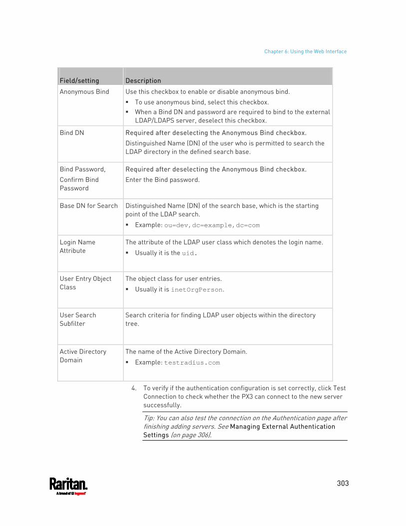
Chapter 6: Using the Web Interface
303
Field/setting Description
Anonymous Bind Use this checkbox to enable or disable anonymous bind. To use anonymous bind, select this checkbox. When a Bind DN and password are required to bind to the external
LDAP/LDAPS server, deselect this checkbox.
Bind DN Required after deselecting the Anonymous Bind checkbox. Distinguished Name (DN) of the user who is permitted to search the LDAP directory in the defined search base.
Bind Password, Confirm Bind Password
Required after deselecting the Anonymous Bind checkbox. Enter the Bind password.
Base DN for Search Distinguished Name (DN) of the search base, which is the starting point of the LDAP search.
Example: ou=dev,dc=example,dc=com
Login Name Attribute
The attribute of the LDAP user class which denotes the login name.
Usually it is the uid.
User Entry Object Class
The object class for user entries.
Usually it is inetOrgPerson.
User Search Subfilter
Search criteria for finding LDAP user objects within the directory tree.
Active Directory Domain
The name of the Active Directory Domain.
Example: testradius.com
4. To verify if the authentication configuration is set correctly, click Test Connection to check whether the PX3 can connect to the new server successfully.
Tip: You can also test the connection on the Authentication page after finishing adding servers. See Managing External Authentication Settings (on page 306).
Chapter 6: Using the Web Interface
304
5. Click Add Server. The new LDAP server is listed on the Authentication page.
6. To add more servers, repeat the same steps. 7. In the Authentication Type field, select LDAP. Otherwise, the LDAP
authentication does not work. 8. Click Save. The LDAP authentication is now in place.
To duplicate LDAP/LDAPS server settings:
If you have added any LDAP/LDAPS server to the PX3, and the server you will add shares identical settings with an existing one, the most convenient way is to duplicate that LDAP/LDAPS server's data and then revise the IP address/host name.
1. Repeat Steps 1 to 2 in the above procedure. 2. Select the "Copy settings from existing LDAP server" checkbox. 3. Click the "Select LDAP Server" field to select the LDAP/LDAPS
server whose settings you want to copy. 4. Modify the IP Address/Hostname field. 5. Click Add Server.
Note: If the PX3 clock and the LDAP server clock are out of sync, the installed TLS certificates, if any, may be considered expired. To ensure proper synchronization, administrators should configure the PX3 and the LDAP server to use the same NTP server(s).
Adding Radius Servers
To use Radius authentication, enable it and enter the information you have gathered.
Note that you must enter information in the fields showing the message 'required.'
To add Radius servers: 1. Choose Device Settings > Security > Authentication. 2. Click New in the Radius section. 3. Enter information.
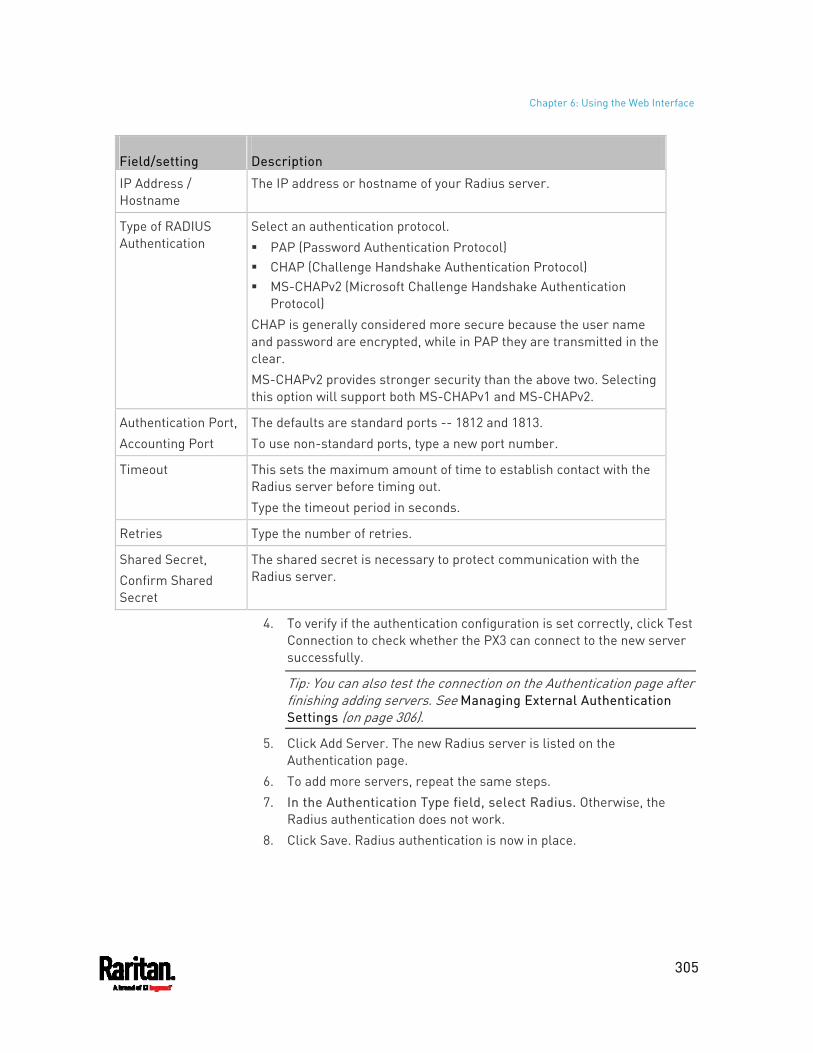
Chapter 6: Using the Web Interface
305
Field/setting Description
IP Address / Hostname
The IP address or hostname of your Radius server.
Type of RADIUS Authentication
Select an authentication protocol. PAP (Password Authentication Protocol) CHAP (Challenge Handshake Authentication Protocol) MS-CHAPv2 (Microsoft Challenge Handshake Authentication
Protocol) CHAP is generally considered more secure because the user name and password are encrypted, while in PAP they are transmitted in the clear. MS-CHAPv2 provides stronger security than the above two. Selecting this option will support both MS-CHAPv1 and MS-CHAPv2.
Authentication Port, Accounting Port
The defaults are standard ports -- 1812 and 1813. To use non-standard ports, type a new port number.
Timeout This sets the maximum amount of time to establish contact with the Radius server before timing out. Type the timeout period in seconds.
Retries Type the number of retries.
Shared Secret, Confirm Shared Secret
The shared secret is necessary to protect communication with the Radius server.
4. To verify if the authentication configuration is set correctly, click Test Connection to check whether the PX3 can connect to the new server successfully.
Tip: You can also test the connection on the Authentication page after finishing adding servers. See Managing External Authentication Settings (on page 306).
5. Click Add Server. The new Radius server is listed on the Authentication page.
6. To add more servers, repeat the same steps. 7. In the Authentication Type field, select Radius. Otherwise, the
Radius authentication does not work. 8. Click Save. Radius authentication is now in place.
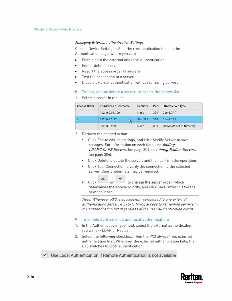
Chapter 6: Using the Web Interface
306
Managing External Authentication Settings
Choose Device Settings > Security > Authentication to open the Authentication page, where you can:
Enable both the external and local authentication Edit or delete a server Resort the access order of servers Test the connection to a server Disable external authentication without removing servers
To test, edit or delete a server, or resort the server list: 1. Select a server in the list.
2. Perform the desired action.
Click Edit to edit its settings, and click Modify Server to save changes. For information on each field, see Adding LDAP/LDAPS Servers (on page 301) or Adding Radius Servers (on page 304).
Click Delete to delete the server, and then confirm the operation. Click Test Connection to verify the connection to the selected
server. User credentials may be required.
Click or to change the server order, which determines the access priority, and click Save Order to save the new sequence.
Note: Whenever PX3 is successfully connected to one external authentication server, it STOPS trying access to remaining servers in the authentication list regardless of the user authentication result.
To enable both external and local authentication: 1. In the Authentication Type field, select the external authentication
you want -- LDAP or Radius. 2. Select the following checkbox. Then the PX3 always tries external
authentication first. Whenever the external authentication fails, the PX3 switches to local authentication.
Chapter 6: Using the Web Interface
307
3. Click Save.
To disable external authentication: 1. In the Authentication Type, select Local. 2. Click Save.
Configuring Login Settings
Choose Device Settings > Security > Login Settings to open the Login Settings page, where you can:
Configure the user blocking feature.
Note: The user blocking function applies only to local authentication instead of external authentication through AA servers.
Determine the timeout period for any inactive user. Prevent simultaneous logins using the same login name.
To configure user blocking: 1. To enable the user blocking feature, select the "Block user on login
failure" checkbox.
2. In the "Block timeout" field, type a value or click to select a time option. This setting determines how long the user is blocked. If you type a value, the value must be followed by a time unit,
such as '4 min.' See Time Units (on page 161). 3. In the "Maximum number of failed logins" field, type a number. This
is the maximum number of login failure the user is permitted before the user is blocked from accessing the PX3.
4. Click Save.
Tip: If any user blocking event occurs, you can unblock that user manually by using the "unblock" CLI command over a local connection. See Unblocking a User (on page 633).
To set limitations for login timeout and use of identical login names:
1. In the "Idle timeout period" field, type a value or click to select a time option. This setting determines how long users are permitted to stay idle before being forced to log out. If you type a value, the value must be followed by a time unit,
such as '4 min.' See Time Units (on page 161).
Chapter 6: Using the Web Interface
308
Keep the idle timeout to 20 minutes or less if possible. This reduces the number of idle sessions connected, and the number of simultaneous commands sent to the PX3.
2. Select the "Prevent concurrent login with same username" checkbox if intending to prevent multiple persons from using the same login name simultaneously.
3. Click Save.
Configuring Password Policy
Choose Device Settings > Security > Password Policy to open the Password Policy page, where you can:
Force users to use strong passwords. Force users to change passwords at a regular interval -- that is,
password aging.
Use of strong passwords makes it more difficult for intruders to crack user passwords and access the PX3.
To configure password aging: 1. Select the 'Enabled' checkbox of Password Aging.
2. In the Password Aging Interval field, type a value or click to select a time option. This setting determines how often users are requested to change their passwords. If you type a value, the value must be followed by a time unit,
such as '10 d.' See Time Units (on page 161). 3. Click Save.
To force users to create strong passwords: 1. Select the 'Enabled' checkbox of Strong Passwords to activate the
strong password feature. The following are the default settings:
Minimum length = 8 characters
Maximum length = 32 characters
At least one lowercase character = Required
At least one uppercase character = Required
At least one numeric character = Required
At least one special character = Required
Number of forbidden previous passwords = 5
Chapter 6: Using the Web Interface
309
Note: The maximum password length accepted by PX3 is 64 characters.
2. Make changes to the default settings as needed. 3. Click Save.
Enabling the Restricted Service Agreement
The restricted service agreement feature, if enabled, forces users to read a security agreement when they log in to the PX3.
Users must accept the agreement, or they cannot log in.
An event notifying you if a user has accepted or declined the agreement can be generated. See Default Log Messages (on page 321)
To enable the service agreement: 1. Click Device Settings > Security > Service Agreement. 2. Select the Enforce Restricted Service Agreement checkbox. 3. Edit or paste the content as needed.
A maximum of 10,000 characters can be entered. 4. Click Save.
Login manner after enabling the service agreement:
After the Restricted Service Agreement feature is enabled, the agreement's content is displayed on the login screen.
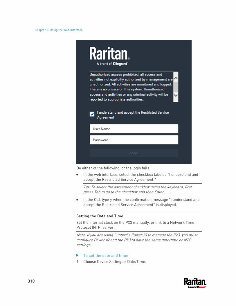
Chapter 6: Using the Web Interface
310
Do either of the following, or the login fails:
In the web interface, select the checkbox labeled "I understand and accept the Restricted Service Agreement."
Tip: To select the agreement checkbox using the keyboard, first press Tab to go to the checkbox and then Enter.
In the CLI, type y when the confirmation message "I understand and accept the Restricted Service Agreement" is displayed.
Setting the Date and Time
Set the internal clock on the PX3 manually, or link to a Network Time Protocol (NTP) server.
Note: If you are using Sunbird's Power IQ to manage the PX3, you must configure Power IQ and the PX3 to have the same date/time or NTP settings.
To set the date and time: 1. Choose Device Settings > Date/Time.
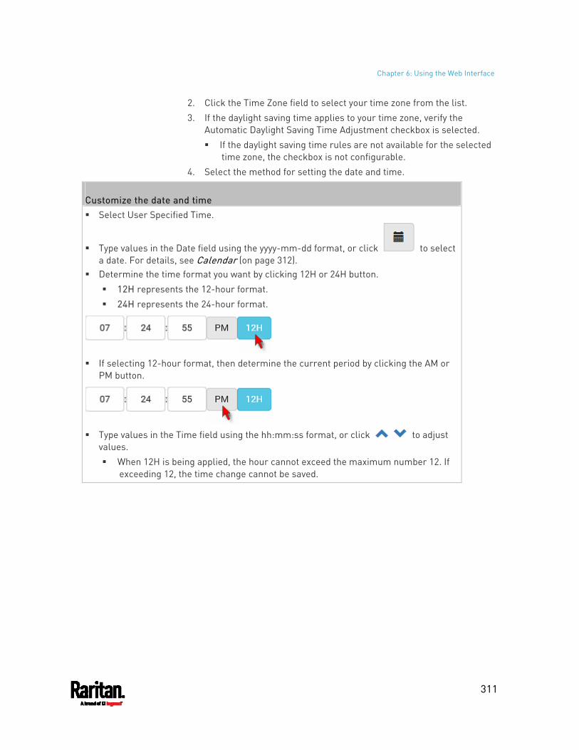
Chapter 6: Using the Web Interface
311
2. Click the Time Zone field to select your time zone from the list. 3. If the daylight saving time applies to your time zone, verify the
Automatic Daylight Saving Time Adjustment checkbox is selected. If the daylight saving time rules are not available for the selected
time zone, the checkbox is not configurable. 4. Select the method for setting the date and time.
Customize the date and time Select User Specified Time.
Type values in the Date field using the yyyy-mm-dd format, or click to select a date. For details, see Calendar (on page 312).
Determine the time format you want by clicking 12H or 24H button. 12H represents the 12-hour format. 24H represents the 24-hour format.
If selecting 12-hour format, then determine the current period by clicking the AM or
PM button.
Type values in the Time field using the hh:mm:ss format, or click to adjust
values. When 12H is being applied, the hour cannot exceed the maximum number 12. If
exceeding 12, the time change cannot be saved.
Chapter 6: Using the Web Interface
312
Use the NTP server Select "Synchronize with NTP server." There are two ways to assign the NTP servers:
To use the DHCP-assigned NTP servers, DO NOT enter any NTP servers for the First and Second time server. DHCP-assigned NTP servers are available only when either IPv4 or IPv6 DHCP is enabled.
To use the manually-specified NTP servers, specify the primary NTP server in the "First time server" field. A secondary NTP server is optional. Click Check NTP Servers to verify the validity and accessibility of the manually-specified NTP servers.
5. Click Save.
PX3 follows the NTP server sanity check per the IETF RFC. If your PX3 has problems synchronizing with a Windows NTP server, see Windows NTP Server Synchronization Solution (on page 313).
Calendar
The calendar icon in the Date field is a convenient tool to select a custom date. Click it and a calendar similar to the following appears.
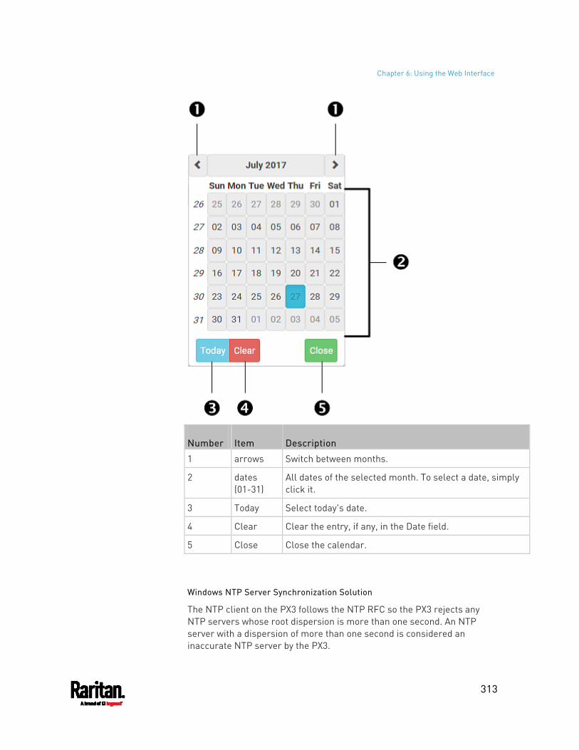
Chapter 6: Using the Web Interface
313
Number Item Description
1 arrows Switch between months.
2 dates (01-31)
All dates of the selected month. To select a date, simply click it.
3 Today Select today's date.
4 Clear Clear the entry, if any, in the Date field.
5 Close Close the calendar.
Windows NTP Server Synchronization Solution
The NTP client on the PX3 follows the NTP RFC so the PX3 rejects any NTP servers whose root dispersion is more than one second. An NTP server with a dispersion of more than one second is considered an inaccurate NTP server by the PX3.
Chapter 6: Using the Web Interface
314
Note: For information on NTP RFC, visit http://tools.ietf.org/html/rfc4330 - http://tools.ietf.org/html/rfc4330 to refer to section 5.
Windows NTP servers may have a root dispersion of more than one second, and therefore cannot synchronize with the PX3. When the NTP synchronization issue occurs, change the dispersion settings to resolve it.
To change the Windows NTP's root dispersion settings: 1. Access the registry settings associated with the root dispersion on
the Windows NTP server. HKEY_LOCAL_MACHINE\SYSTEM\CurrentControlSet\Services\W32Time\Config
2. AnnounceFlags must be set to 0x05 or 0x06. 0x05 = 0x01 (Always time server) and 0x04 (Always reliable time
server) 0x06 = 0x02 (Automatic time server) and 0x04 (Always reliable
time server)
Note: Do NOT use 0x08 (Automatic reliable time server) because its dispersion starts at a high value and then gradually decreases to one second or lower.
3. LocalClockDispersion must be set to 0.
Event Rules and Actions
A benefit of the product's intelligence is its ability to notify you of or react to a change in conditions. This event notification or reaction is an "event rule."
An event rule consists of two parts:
Event: This is the situation where the PX3 or a device connected to it meets a certain condition. For example, the inlet's voltage reaches the warning level.
Action: This is the response to the event. For example, the PX3 notifies the system administrator of the event via email.
If you want the PX3 to perform one action at a regular interval instead of waiting until an event occurs, you can schedule that action. For example, you can make the PX3 email the temperature report every hour.
Note that you need the Administrator Privileges to configure event rules.
To create an event rule: 1. Choose Device Settings > Event Rules.
Chapter 6: Using the Web Interface
315
2. If the needed action is not available yet, create it by clicking
. a. Assign a name to this action. b. Select the desired action and configure it as needed. c. Click Create. For details, see Available Actions (on page 336).
3. Click to create a new rule. a. Assign a name to this rule. b. Make sure the Enabled checkbox is selected, or the new event
rule does not work. c. In the Event field, select the event to which you want the PX3 to
react. d. In the Available Actions field, select the desired action(s) to
respond to the selected event. e. Click Create. For details, see Built-in Rules and Rule Configuration (on page 315).
To create a scheduled action: 1. If the needed action is not available yet, create it by clicking
. See above.
Note: When creating scheduled actions, available actions are less than usual because it is meaningless to schedule certain actions like "Alarm," "Log event message," "Send email," "Syslog message" and the like.
2. Click to schedule the desired action. a. Assign a name to this scheduled action. b. Make sure the Enabled checkbox is selected, or the PX3 does not
perform this scheduled action. c. Set the interval time, which ranges from every minute to yearly. d. In the Available Actions field, select the desired action(s). e. Click Create. For details, see Scheduling an Action (on page 356).
Built-in Rules and Rule Configuration
PX3 is shipped with four built-in event rules, which cannot be deleted. If the built-in event rules do not satisfy your needs, create new rules.
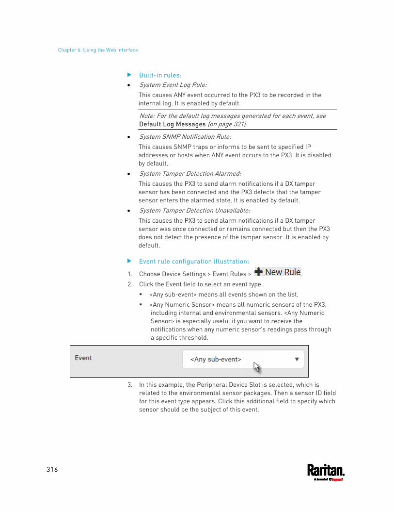
Chapter 6: Using the Web Interface
316
Built-in rules: System Event Log Rule:
This causes ANY event occurred to the PX3 to be recorded in the internal log. It is enabled by default.
Note: For the default log messages generated for each event, see Default Log Messages (on page 321).
System SNMP Notification Rule: This causes SNMP traps or informs to be sent to specified IP addresses or hosts when ANY event occurs to the PX3. It is disabled by default.
System Tamper Detection Alarmed: This causes the PX3 to send alarm notifications if a DX tamper sensor has been connected and the PX3 detects that the tamper sensor enters the alarmed state. It is enabled by default.
System Tamper Detection Unavailable: This causes the PX3 to send alarm notifications if a DX tamper sensor was once connected or remains connected but then the PX3 does not detect the presence of the tamper sensor. It is enabled by default.
Event rule configuration illustration:
1. Choose Device Settings > Event Rules > . 2. Click the Event field to select an event type.
<Any sub-event> means all events shown on the list. <Any Numeric Sensor> means all numeric sensors of the PX3,
including internal and environmental sensors. <Any Numeric Sensor> is especially useful if you want to receive the notifications when any numeric sensor's readings pass through a specific threshold.
3. In this example, the Peripheral Device Slot is selected, which is
related to the environmental sensor packages. Then a sensor ID field for this event type appears. Click this additional field to specify which sensor should be the subject of this event.
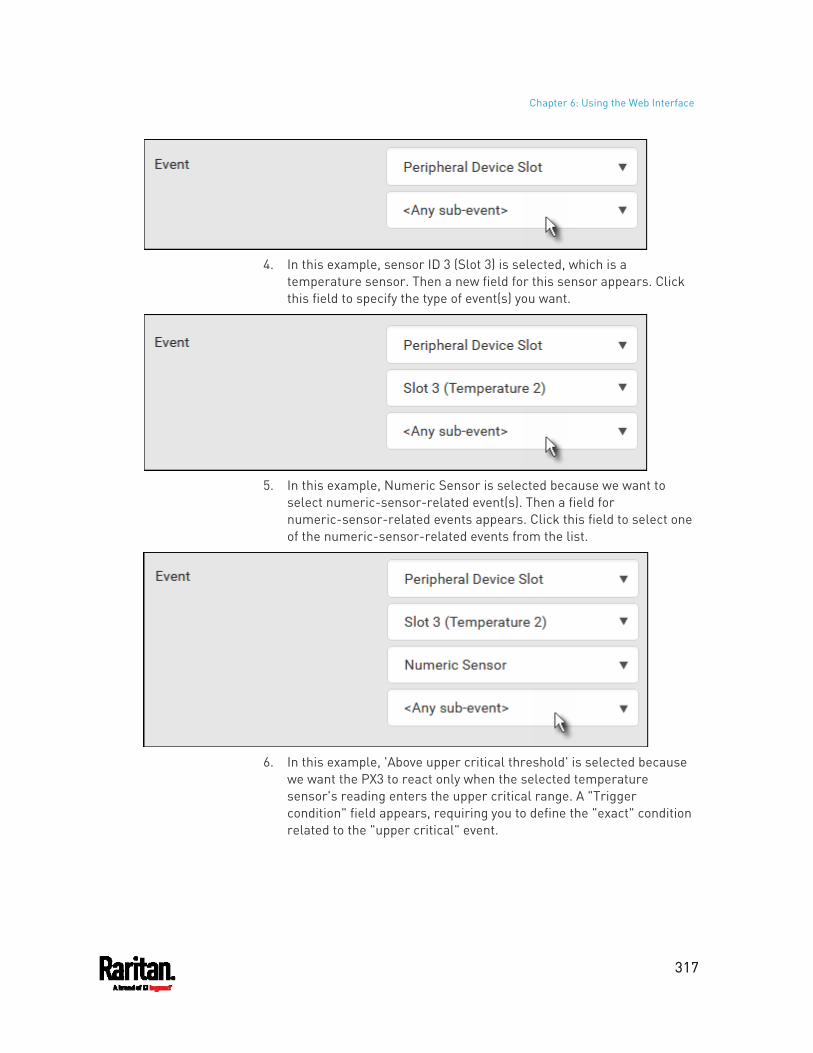
Chapter 6: Using the Web Interface
317
4. In this example, sensor ID 3 (Slot 3) is selected, which is a
temperature sensor. Then a new field for this sensor appears. Click this field to specify the type of event(s) you want.
5. In this example, Numeric Sensor is selected because we want to
select numeric-sensor-related event(s). Then a field for numeric-sensor-related events appears. Click this field to select one of the numeric-sensor-related events from the list.
6. In this example, 'Above upper critical threshold' is selected because
we want the PX3 to react only when the selected temperature sensor's reading enters the upper critical range. A "Trigger condition" field appears, requiring you to define the "exact" condition related to the "upper critical" event.
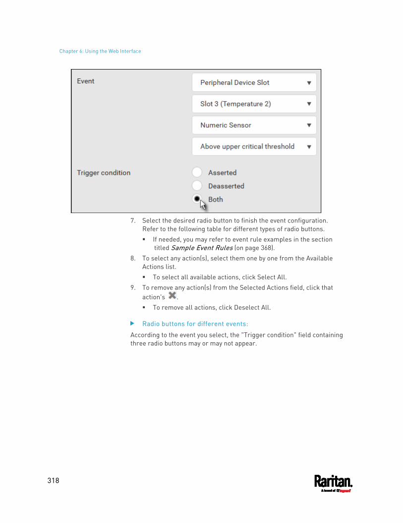
Chapter 6: Using the Web Interface
318
7. Select the desired radio button to finish the event configuration.
Refer to the following table for different types of radio buttons. If needed, you may refer to event rule examples in the section
titled Sample Event Rules (on page 368). 8. To select any action(s), select them one by one from the Available
Actions list. To select all available actions, click Select All.
9. To remove any action(s) from the Selected Actions field, click that action's . To remove all actions, click Deselect All.
Radio buttons for different events:
According to the event you select, the "Trigger condition" field containing three radio buttons may or may not appear.
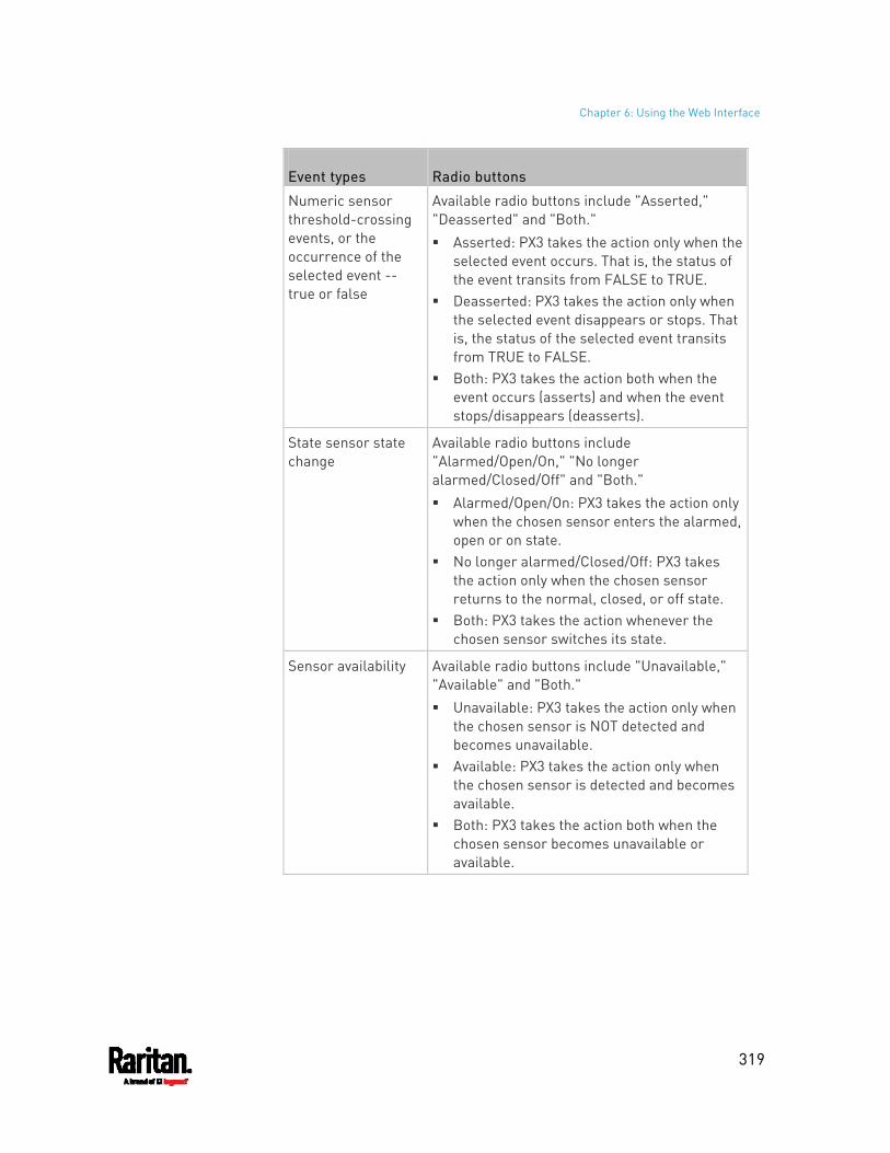
Chapter 6: Using the Web Interface
319
Event types Radio buttons
Numeric sensor threshold-crossing events, or the occurrence of the selected event -- true or false
Available radio buttons include "Asserted," "Deasserted" and "Both." Asserted: PX3 takes the action only when the
selected event occurs. That is, the status of the event transits from FALSE to TRUE.
Deasserted: PX3 takes the action only when the selected event disappears or stops. That is, the status of the selected event transits from TRUE to FALSE.
Both: PX3 takes the action both when the event occurs (asserts) and when the event stops/disappears (deasserts).
State sensor state change
Available radio buttons include "Alarmed/Open/On," "No longer alarmed/Closed/Off" and "Both." Alarmed/Open/On: PX3 takes the action only
when the chosen sensor enters the alarmed, open or on state.
No longer alarmed/Closed/Off: PX3 takes the action only when the chosen sensor returns to the normal, closed, or off state.
Both: PX3 takes the action whenever the chosen sensor switches its state.
Sensor availability Available radio buttons include "Unavailable," "Available" and "Both." Unavailable: PX3 takes the action only when
the chosen sensor is NOT detected and becomes unavailable.
Available: PX3 takes the action only when the chosen sensor is detected and becomes available.
Both: PX3 takes the action both when the chosen sensor becomes unavailable or available.
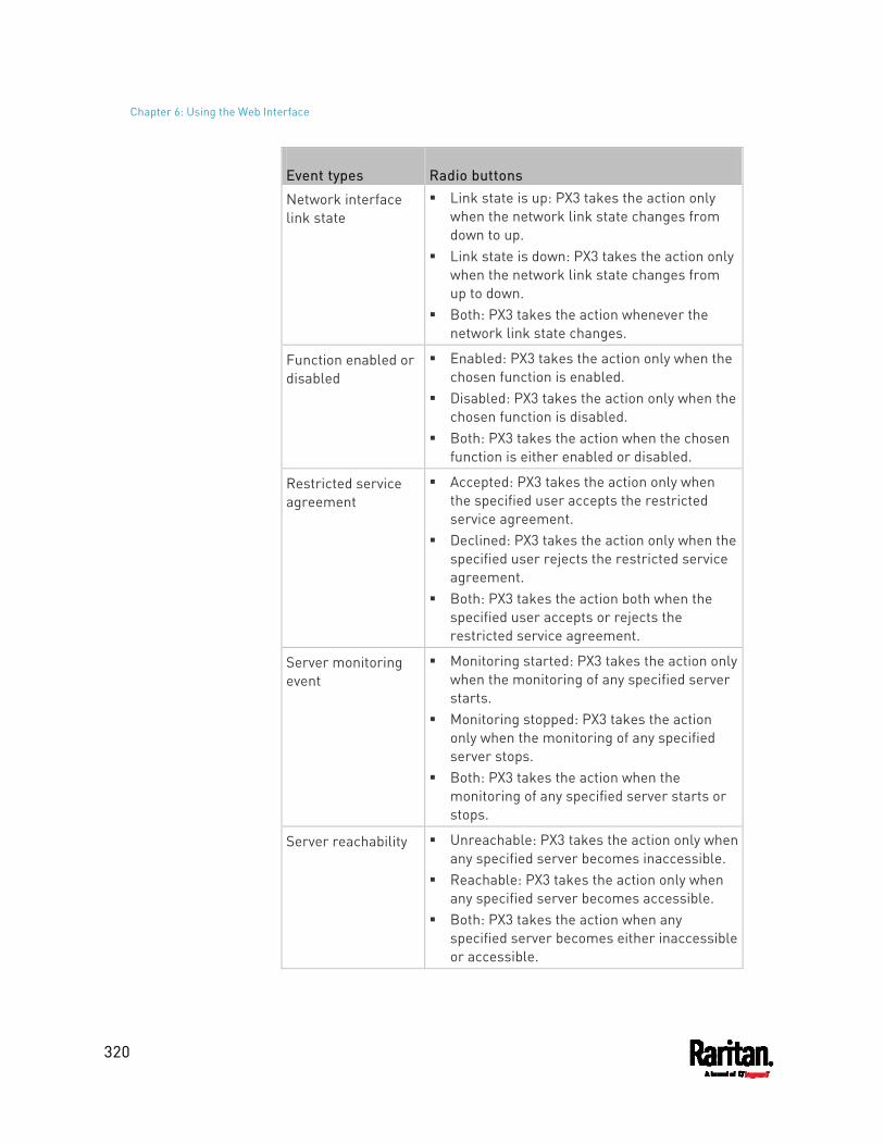
Chapter 6: Using the Web Interface
320
Event types Radio buttons
Network interface link state
Link state is up: PX3 takes the action only when the network link state changes from down to up.
Link state is down: PX3 takes the action only when the network link state changes from up to down.
Both: PX3 takes the action whenever the network link state changes.
Function enabled or disabled
Enabled: PX3 takes the action only when the chosen function is enabled.
Disabled: PX3 takes the action only when the chosen function is disabled.
Both: PX3 takes the action when the chosen function is either enabled or disabled.
Restricted service agreement
Accepted: PX3 takes the action only when the specified user accepts the restricted service agreement.
Declined: PX3 takes the action only when the specified user rejects the restricted service agreement.
Both: PX3 takes the action both when the specified user accepts or rejects the restricted service agreement.
Server monitoring event
Monitoring started: PX3 takes the action only when the monitoring of any specified server starts.
Monitoring stopped: PX3 takes the action only when the monitoring of any specified server stops.
Both: PX3 takes the action when the monitoring of any specified server starts or stops.
Server reachability Unreachable: PX3 takes the action only when any specified server becomes inaccessible.
Reachable: PX3 takes the action only when any specified server becomes accessible.
Both: PX3 takes the action when any specified server becomes either inaccessible or accessible.
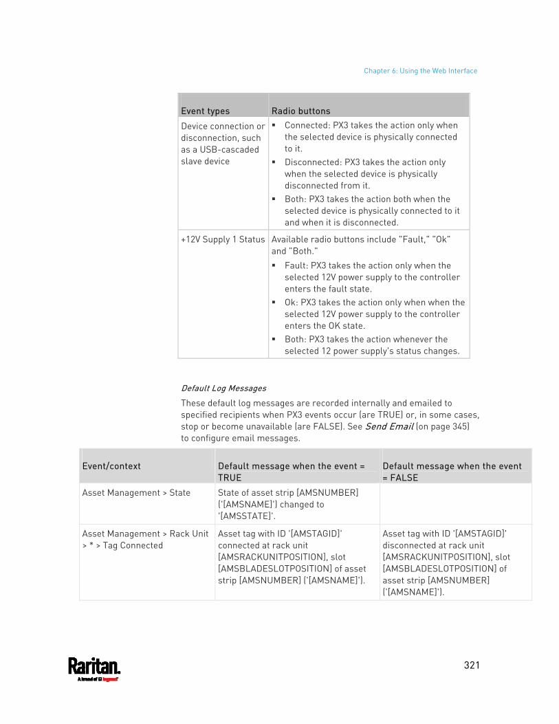
Chapter 6: Using the Web Interface
321
Event types Radio buttons
Device connection or disconnection, such as a USB-cascaded slave device
Connected: PX3 takes the action only when the selected device is physically connected to it.
Disconnected: PX3 takes the action only when the selected device is physically disconnected from it.
Both: PX3 takes the action both when the selected device is physically connected to it and when it is disconnected.
+12V Supply 1 Status Available radio buttons include "Fault," "Ok" and "Both." Fault: PX3 takes the action only when the
selected 12V power supply to the controller enters the fault state.
Ok: PX3 takes the action only when when the selected 12V power supply to the controller enters the OK state.
Both: PX3 takes the action whenever the selected 12 power supply's status changes.
Default Log Messages
These default log messages are recorded internally and emailed to specified recipients when PX3 events occur (are TRUE) or, in some cases, stop or become unavailable (are FALSE). See Send Email (on page 345) to configure email messages.
Event/context Default message when the event = TRUE
Default message when the event = FALSE
Asset Management > State State of asset strip [AMSNUMBER] ('[AMSNAME]') changed to '[AMSSTATE]'.
Asset Management > Rack Unit > * > Tag Connected
Asset tag with ID '[AMSTAGID]' connected at rack unit [AMSRACKUNITPOSITION], slot [AMSBLADESLOTPOSITION] of asset strip [AMSNUMBER] ('[AMSNAME]').
Asset tag with ID '[AMSTAGID]' disconnected at rack unit [AMSRACKUNITPOSITION], slot [AMSBLADESLOTPOSITION] of asset strip [AMSNUMBER] ('[AMSNAME]').
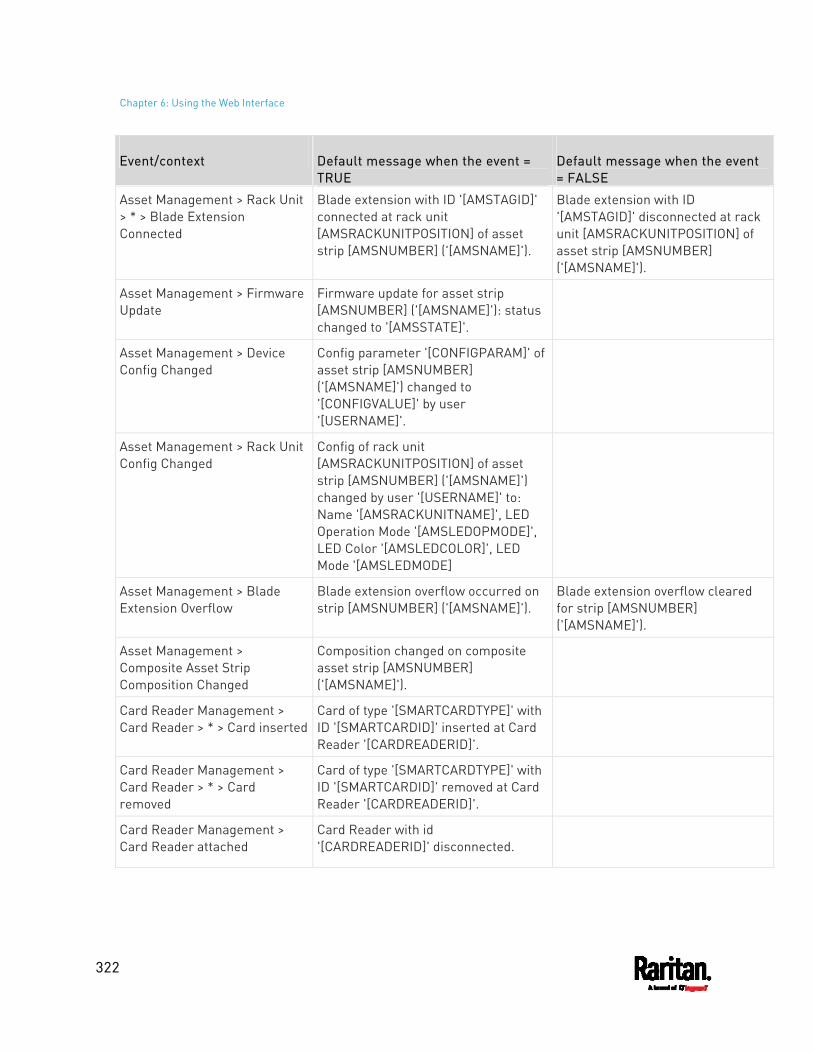
Chapter 6: Using the Web Interface
322
Event/context Default message when the event = TRUE
Default message when the event = FALSE
Asset Management > Rack Unit > * > Blade Extension Connected
Blade extension with ID '[AMSTAGID]' connected at rack unit [AMSRACKUNITPOSITION] of asset strip [AMSNUMBER] ('[AMSNAME]').
Blade extension with ID '[AMSTAGID]' disconnected at rack unit [AMSRACKUNITPOSITION] of asset strip [AMSNUMBER] ('[AMSNAME]').
Asset Management > Firmware Update
Firmware update for asset strip [AMSNUMBER] ('[AMSNAME]'): status changed to '[AMSSTATE]'.
Asset Management > Device Config Changed
Config parameter '[CONFIGPARAM]' of asset strip [AMSNUMBER] ('[AMSNAME]') changed to '[CONFIGVALUE]' by user '[USERNAME]'.
Asset Management > Rack Unit Config Changed
Config of rack unit [AMSRACKUNITPOSITION] of asset strip [AMSNUMBER] ('[AMSNAME]') changed by user '[USERNAME]' to: Name '[AMSRACKUNITNAME]', LED Operation Mode '[AMSLEDOPMODE]', LED Color '[AMSLEDCOLOR]', LED Mode '[AMSLEDMODE]
Asset Management > Blade Extension Overflow
Blade extension overflow occurred on strip [AMSNUMBER] ('[AMSNAME]').
Blade extension overflow cleared for strip [AMSNUMBER] ('[AMSNAME]').
Asset Management > Composite Asset Strip Composition Changed
Composition changed on composite asset strip [AMSNUMBER] ('[AMSNAME]').
Card Reader Management > Card Reader > * > Card inserted
Card of type '[SMARTCARDTYPE]' with ID '[SMARTCARDID]' inserted at Card Reader '[CARDREADERID]'.
Card Reader Management > Card Reader > * > Card removed
Card of type '[SMARTCARDTYPE]' with ID '[SMARTCARDID]' removed at Card Reader '[CARDREADERID]'.
Card Reader Management > Card Reader attached
Card Reader with id '[CARDREADERID]' disconnected.
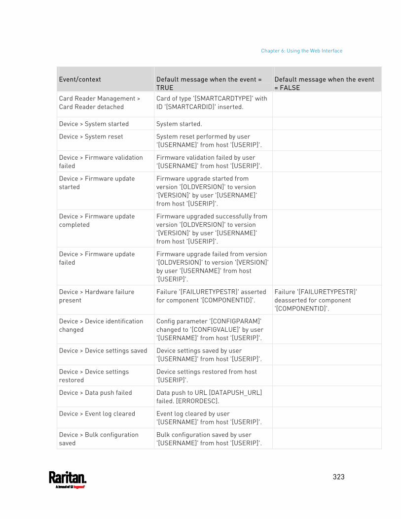
Chapter 6: Using the Web Interface
323
Event/context Default message when the event = TRUE
Default message when the event = FALSE
Card Reader Management > Card Reader detached
Card of type '[SMARTCARDTYPE]' with ID '[SMARTCARDID]' inserted.
Device > System started System started.
Device > System reset System reset performed by user '[USERNAME]' from host '[USERIP]'.
Device > Firmware validation failed
Firmware validation failed by user '[USERNAME]' from host '[USERIP]'.
Device > Firmware update started
Firmware upgrade started from version '[OLDVERSION]' to version '[VERSION]' by user '[USERNAME]' from host '[USERIP]'.
Device > Firmware update completed
Firmware upgraded successfully from version '[OLDVERSION]' to version '[VERSION]' by user '[USERNAME]' from host '[USERIP]'.
Device > Firmware update failed
Firmware upgrade failed from version '[OLDVERSION]' to version '[VERSION]' by user '[USERNAME]' from host '[USERIP]'.
Device > Hardware failure present
Failure '[FAILURETYPESTR]' asserted for component '[COMPONENTID]'.
Failure '[FAILURETYPESTR]' deasserted for component '[COMPONENTID]'.
Device > Device identification changed
Config parameter '[CONFIGPARAM]' changed to '[CONFIGVALUE]' by user '[USERNAME]' from host '[USERIP]'.
Device > Device settings saved Device settings saved by user '[USERNAME]' from host '[USERIP]'.
Device > Device settings restored
Device settings restored from host '[USERIP]'.
Device > Data push failed Data push to URL [DATAPUSH_URL] failed. [ERRORDESC].
Device > Event log cleared Event log cleared by user '[USERNAME]' from host '[USERIP]'.
Device > Bulk configuration saved
Bulk configuration saved by user '[USERNAME]' from host '[USERIP]'.
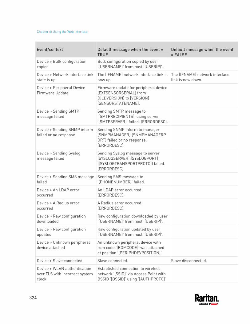
Chapter 6: Using the Web Interface
324
Event/context Default message when the event = TRUE
Default message when the event = FALSE
Device > Bulk configuration copied
Bulk configuration copied by user '[USERNAME]' from host '[USERIP]'.
Device > Network interface link state is up
The [IFNAME] network interface link is now up.
The [IFNAME] network interface link is now down.
Device > Peripheral Device Firmware Update
Firmware update for peripheral device [EXTSENSORSERIAL] from [OLDVERSION] to [VERSION] [SENSORSTATENAME].
Device > Sending SMTP message failed
Sending SMTP message to '[SMTPRECIPIENTS]' using server '[SMTPSERVER]' failed. [ERRORDESC].
Device > Sending SNMP inform failed or no response
Sending SNMP inform to manager [SNMPMANAGER]:[SNMPMANAGERPORT] failed or no response. [ERRORDESC].
Device > Sending Syslog message failed
Sending Syslog message to server [SYSLOGSERVER]:[SYSLOGPORT] ([SYSLOGTRANSPORTPROTO]) failed. [ERRORDESC].
Device > Sending SMS message failed
Sending SMS message to '[PHONENUMBER]' failed.
Device > An LDAP error occurred
An LDAP error occurred: [ERRORDESC].
Device > A Radius error occurred
A Radius error occurred: [ERRORDESC].
Device > Raw configuration downloaded
Raw configuration downloaded by user '[USERNAME]' from host '[USERIP]'.
Device > Raw configuration updated
Raw configuration updated by user '[USERNAME]' from host '[USERIP]'.
Device > Unknown peripheral device attached
An unknown peripheral device with rom code '[ROMCODE]' was attached at position '[PERIPHDEVPOSITION]'.
Device > Slave connected Slave connected. Slave disconnected.
Device > WLAN authentication over TLS with incorrect system clock
Established connection to wireless network '[SSID]' via Access Point with BSSID '[BSSID]' using '[AUTHPROTO]'
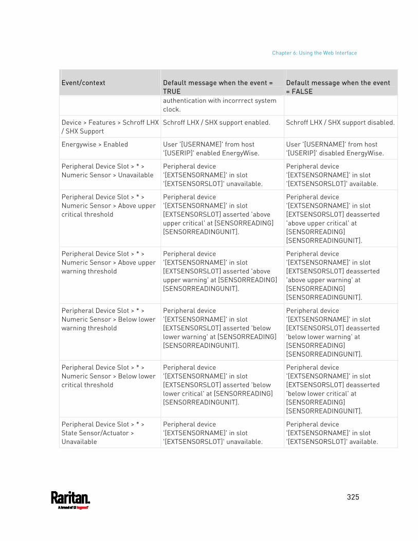
Chapter 6: Using the Web Interface
325
Event/context Default message when the event = TRUE
Default message when the event = FALSE
authentication with incorrrect system clock.
Device > Features > Schroff LHX / SHX Support
Schroff LHX / SHX support enabled. Schroff LHX / SHX support disabled.
Energywise > Enabled User '[USERNAME]' from host '[USERIP]' enabled EnergyWise.
User '[USERNAME]' from host '[USERIP]' disabled EnergyWise.
Peripheral Device Slot > * > Numeric Sensor > Unavailable
Peripheral device '[EXTSENSORNAME]' in slot '[EXTSENSORSLOT]' unavailable.
Peripheral device '[EXTSENSORNAME]' in slot '[EXTSENSORSLOT]' available.
Peripheral Device Slot > * > Numeric Sensor > Above upper critical threshold
Peripheral device '[EXTSENSORNAME]' in slot [EXTSENSORSLOT] asserted 'above upper critical' at [SENSORREADING] [SENSORREADINGUNIT].
Peripheral device '[EXTSENSORNAME]' in slot [EXTSENSORSLOT] deasserted 'above upper critical' at [SENSORREADING] [SENSORREADINGUNIT].
Peripheral Device Slot > * > Numeric Sensor > Above upper warning threshold
Peripheral device '[EXTSENSORNAME]' in slot [EXTSENSORSLOT] asserted 'above upper warning' at [SENSORREADING] [SENSORREADINGUNIT].
Peripheral device '[EXTSENSORNAME]' in slot [EXTSENSORSLOT] deasserted 'above upper warning' at [SENSORREADING] [SENSORREADINGUNIT].
Peripheral Device Slot > * > Numeric Sensor > Below lower warning threshold
Peripheral device '[EXTSENSORNAME]' in slot [EXTSENSORSLOT] asserted 'below lower warning' at [SENSORREADING] [SENSORREADINGUNIT].
Peripheral device '[EXTSENSORNAME]' in slot [EXTSENSORSLOT] deasserted 'below lower warning' at [SENSORREADING] [SENSORREADINGUNIT].
Peripheral Device Slot > * > Numeric Sensor > Below lower critical threshold
Peripheral device '[EXTSENSORNAME]' in slot [EXTSENSORSLOT] asserted 'below lower critical' at [SENSORREADING] [SENSORREADINGUNIT].
Peripheral device '[EXTSENSORNAME]' in slot [EXTSENSORSLOT] deasserted 'below lower critical' at [SENSORREADING] [SENSORREADINGUNIT].
Peripheral Device Slot > * > State Sensor/Actuator > Unavailable
Peripheral device '[EXTSENSORNAME]' in slot '[EXTSENSORSLOT]' unavailable.
Peripheral device '[EXTSENSORNAME]' in slot '[EXTSENSORSLOT]' available.
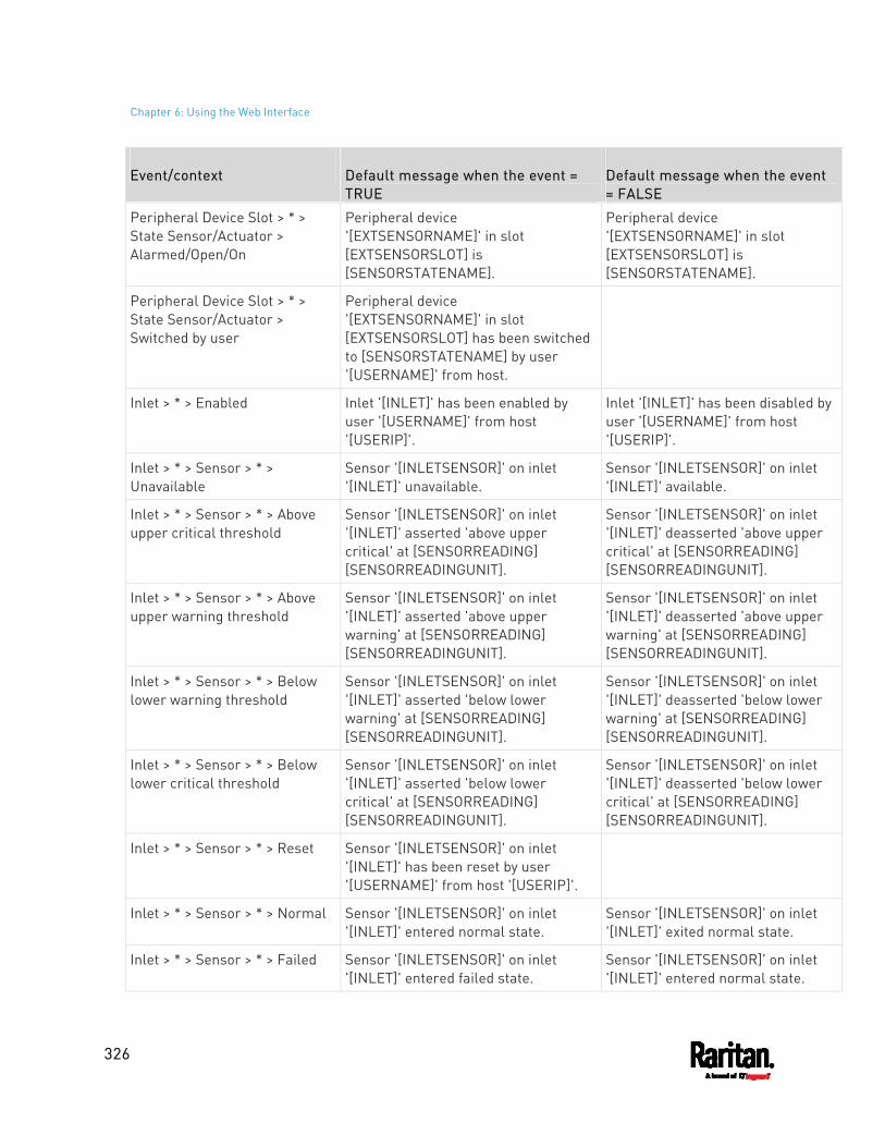
Chapter 6: Using the Web Interface
326
Event/context Default message when the event = TRUE
Default message when the event = FALSE
Peripheral Device Slot > * > State Sensor/Actuator > Alarmed/Open/On
Peripheral device '[EXTSENSORNAME]' in slot [EXTSENSORSLOT] is [SENSORSTATENAME].
Peripheral device '[EXTSENSORNAME]' in slot [EXTSENSORSLOT] is [SENSORSTATENAME].
Peripheral Device Slot > * > State Sensor/Actuator > Switched by user
Peripheral device '[EXTSENSORNAME]' in slot [EXTSENSORSLOT] has been switched to [SENSORSTATENAME] by user '[USERNAME]' from host.
Inlet > * > Enabled Inlet '[INLET]' has been enabled by user '[USERNAME]' from host '[USERIP]'.
Inlet '[INLET]' has been disabled by user '[USERNAME]' from host '[USERIP]'.
Inlet > * > Sensor > * > Unavailable
Sensor '[INLETSENSOR]' on inlet '[INLET]' unavailable.
Sensor '[INLETSENSOR]' on inlet '[INLET]' available.
Inlet > * > Sensor > * > Above upper critical threshold
Sensor '[INLETSENSOR]' on inlet '[INLET]' asserted 'above upper critical' at [SENSORREADING] [SENSORREADINGUNIT].
Sensor '[INLETSENSOR]' on inlet '[INLET]' deasserted 'above upper critical' at [SENSORREADING] [SENSORREADINGUNIT].
Inlet > * > Sensor > * > Above upper warning threshold
Sensor '[INLETSENSOR]' on inlet '[INLET]' asserted 'above upper warning' at [SENSORREADING] [SENSORREADINGUNIT].
Sensor '[INLETSENSOR]' on inlet '[INLET]' deasserted 'above upper warning' at [SENSORREADING] [SENSORREADINGUNIT].
Inlet > * > Sensor > * > Below lower warning threshold
Sensor '[INLETSENSOR]' on inlet '[INLET]' asserted 'below lower warning' at [SENSORREADING] [SENSORREADINGUNIT].
Sensor '[INLETSENSOR]' on inlet '[INLET]' deasserted 'below lower warning' at [SENSORREADING] [SENSORREADINGUNIT].
Inlet > * > Sensor > * > Below lower critical threshold
Sensor '[INLETSENSOR]' on inlet '[INLET]' asserted 'below lower critical' at [SENSORREADING] [SENSORREADINGUNIT].
Sensor '[INLETSENSOR]' on inlet '[INLET]' deasserted 'below lower critical' at [SENSORREADING] [SENSORREADINGUNIT].
Inlet > * > Sensor > * > Reset Sensor '[INLETSENSOR]' on inlet '[INLET]' has been reset by user '[USERNAME]' from host '[USERIP]'.
Inlet > * > Sensor > * > Normal Sensor '[INLETSENSOR]' on inlet '[INLET]' entered normal state.
Sensor '[INLETSENSOR]' on inlet '[INLET]' exited normal state.
Inlet > * > Sensor > * > Failed Sensor '[INLETSENSOR]' on inlet '[INLET]' entered failed state.
Sensor '[INLETSENSOR]' on inlet '[INLET]' entered normal state.
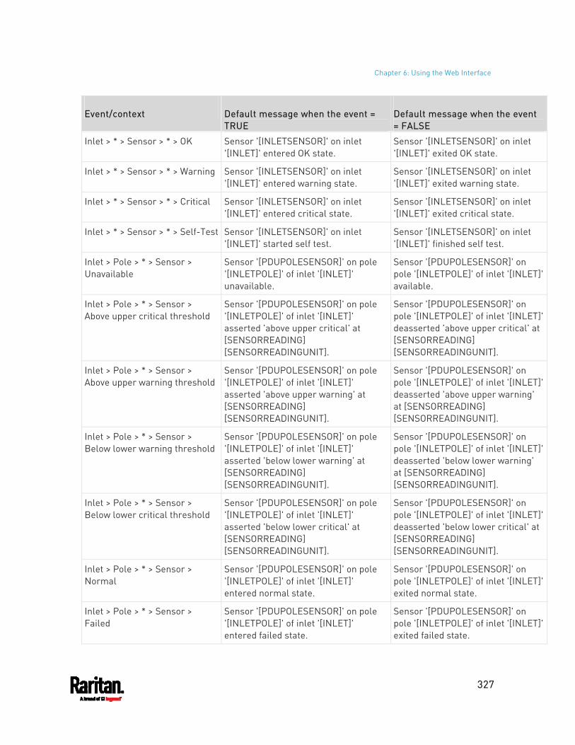
Chapter 6: Using the Web Interface
327
Event/context Default message when the event = TRUE
Default message when the event = FALSE
Inlet > * > Sensor > * > OK Sensor '[INLETSENSOR]' on inlet '[INLET]' entered OK state.
Sensor '[INLETSENSOR]' on inlet '[INLET]' exited OK state.
Inlet > * > Sensor > * > Warning Sensor '[INLETSENSOR]' on inlet '[INLET]' entered warning state.
Sensor '[INLETSENSOR]' on inlet '[INLET]' exited warning state.
Inlet > * > Sensor > * > Critical Sensor '[INLETSENSOR]' on inlet '[INLET]' entered critical state.
Sensor '[INLETSENSOR]' on inlet '[INLET]' exited critical state.
Inlet > * > Sensor > * > Self-Test Sensor '[INLETSENSOR]' on inlet '[INLET]' started self test.
Sensor '[INLETSENSOR]' on inlet '[INLET]' finished self test.
Inlet > Pole > * > Sensor > Unavailable
Sensor '[PDUPOLESENSOR]' on pole '[INLETPOLE]' of inlet '[INLET]' unavailable.
Sensor '[PDUPOLESENSOR]' on pole '[INLETPOLE]' of inlet '[INLET]' available.
Inlet > Pole > * > Sensor > Above upper critical threshold
Sensor '[PDUPOLESENSOR]' on pole '[INLETPOLE]' of inlet '[INLET]' asserted 'above upper critical' at [SENSORREADING] [SENSORREADINGUNIT].
Sensor '[PDUPOLESENSOR]' on pole '[INLETPOLE]' of inlet '[INLET]' deasserted 'above upper critical' at [SENSORREADING] [SENSORREADINGUNIT].
Inlet > Pole > * > Sensor > Above upper warning threshold
Sensor '[PDUPOLESENSOR]' on pole '[INLETPOLE]' of inlet '[INLET]' asserted 'above upper warning' at [SENSORREADING] [SENSORREADINGUNIT].
Sensor '[PDUPOLESENSOR]' on pole '[INLETPOLE]' of inlet '[INLET]' deasserted 'above upper warning' at [SENSORREADING] [SENSORREADINGUNIT].
Inlet > Pole > * > Sensor > Below lower warning threshold
Sensor '[PDUPOLESENSOR]' on pole '[INLETPOLE]' of inlet '[INLET]' asserted 'below lower warning' at [SENSORREADING] [SENSORREADINGUNIT].
Sensor '[PDUPOLESENSOR]' on pole '[INLETPOLE]' of inlet '[INLET]' deasserted 'below lower warning' at [SENSORREADING] [SENSORREADINGUNIT].
Inlet > Pole > * > Sensor > Below lower critical threshold
Sensor '[PDUPOLESENSOR]' on pole '[INLETPOLE]' of inlet '[INLET]' asserted 'below lower critical' at [SENSORREADING] [SENSORREADINGUNIT].
Sensor '[PDUPOLESENSOR]' on pole '[INLETPOLE]' of inlet '[INLET]' deasserted 'below lower critical' at [SENSORREADING] [SENSORREADINGUNIT].
Inlet > Pole > * > Sensor > Normal
Sensor '[PDUPOLESENSOR]' on pole '[INLETPOLE]' of inlet '[INLET]' entered normal state.
Sensor '[PDUPOLESENSOR]' on pole '[INLETPOLE]' of inlet '[INLET]' exited normal state.
Inlet > Pole > * > Sensor > Failed
Sensor '[PDUPOLESENSOR]' on pole '[INLETPOLE]' of inlet '[INLET]' entered failed state.
Sensor '[PDUPOLESENSOR]' on pole '[INLETPOLE]' of inlet '[INLET]' exited failed state.
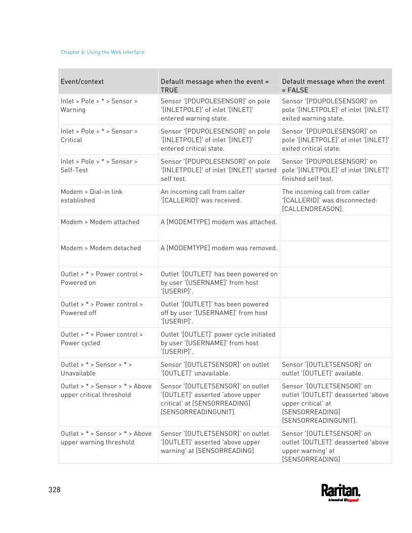
Chapter 6: Using the Web Interface
328
Event/context Default message when the event = TRUE
Default message when the event = FALSE
Inlet > Pole > * > Sensor > Warning
Sensor '[PDUPOLESENSOR]' on pole '[INLETPOLE]' of inlet '[INLET]' entered warning state.
Sensor '[PDUPOLESENSOR]' on pole '[INLETPOLE]' of inlet '[INLET]' exited warning state.
Inlet > Pole > * > Sensor > Critical
Sensor '[PDUPOLESENSOR]' on pole '[INLETPOLE]' of inlet '[INLET]' entered critical state.
Sensor '[PDUPOLESENSOR]' on pole '[INLETPOLE]' of inlet '[INLET]' exited critical state.
Inlet > Pole > * > Sensor > Self-Test
Sensor '[PDUPOLESENSOR]' on pole '[INLETPOLE]' of inlet '[INLET]' started self test.
Sensor '[PDUPOLESENSOR]' on pole '[INLETPOLE]' of inlet '[INLET]' finished self test.
Modem > Dial-in link established
An incoming call from caller '[CALLERID]' was received.
The incoming call from caller '[CALLERID]' was disconnected: [CALLENDREASON].
Modem > Modem attached A [MODEMTYPE] modem was attached.
Modem > Modem detached A [MODEMTYPE] modem was removed.
Outlet > * > Power control > Powered on
Outlet '[OUTLET]' has been powered on by user '[USERNAME]' from host '[USERIP]'.
Outlet > * > Power control > Powered off
Outlet '[OUTLET]' has been powered off by user '[USERNAME]' from host '[USERIP]'.
Outlet > * > Power control > Power cycled
Outlet '[OUTLET]' power cycle initiated by user '[USERNAME]' from host '[USERIP]'.
Outlet > * > Sensor > * > Unavailable
Sensor '[OUTLETSENSOR]' on outlet '[OUTLET]' unavailable.
Sensor '[OUTLETSENSOR]' on outlet '[OUTLET]' available.
Outlet > * > Sensor > * > Above upper critical threshold
Sensor '[OUTLETSENSOR]' on outlet '[OUTLET]' asserted 'above upper critical' at [SENSORREADING] [SENSORREADINGUNIT].
Sensor '[OUTLETSENSOR]' on outlet '[OUTLET]' deasserted 'above upper critical' at [SENSORREADING] [SENSORREADINGUNIT].
Outlet > * > Sensor > * > Above upper warning threshold
Sensor '[OUTLETSENSOR]' on outlet '[OUTLET]' asserted 'above upper warning' at [SENSORREADING]
Sensor '[OUTLETSENSOR]' on outlet '[OUTLET]' deasserted 'above upper warning' at [SENSORREADING]
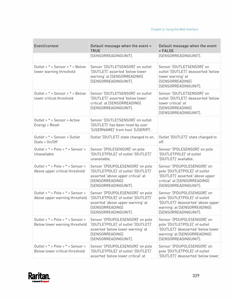
Chapter 6: Using the Web Interface
329
Event/context Default message when the event = TRUE
Default message when the event = FALSE
[SENSORREADINGUNIT]. [SENSORREADINGUNIT].
Outlet > * > Sensor > * > Below lower warning threshold
Sensor '[OUTLETSENSOR]' on outlet '[OUTLET]' asserted 'below lower warning' at [SENSORREADING] [SENSORREADINGUNIT].
Sensor '[OUTLETSENSOR]' on outlet '[OUTLET]' deasserted 'below lower warning' at [SENSORREADING] [SENSORREADINGUNIT].
Outlet > * > Sensor > * > Below lower critical threshold
Sensor '[OUTLETSENSOR]' on outlet '[OUTLET]' asserted 'below lower critical' at [SENSORREADING] [SENSORREADINGUNIT].
Sensor '[OUTLETSENSOR]' on outlet '[OUTLET]' deasserted 'below lower critical' at [SENSORREADING] [SENSORREADINGUNIT].
Outlet > * > Sensor > Active Energy > Reset
Sensor '[OUTLETSENSOR]' on outlet '[OUTLET]' has been reset by user '[USERNAME]' from host '[USERIP]'.
Outlet > * > Sensor > Outlet State > On/Off
Outlet '[OUTLET]' state changed to on. Outlet '[OUTLET]' state changed to off.
Outlet > * > Pole > * > Sensor > Unavailable
Sensor '[POLESENSOR]' on pole '[OUTLETPOLE]' of outlet '[OUTLET]' unavailable.
Sensor '[POLESENSOR]' on pole '[OUTLETPOLE]' of outlet '[OUTLET]' available.
Outlet > * > Pole > * > Sensor > Above upper critical threshold
Sensor '[PDUPOLESENSOR]' on pole '[OUTLETPOLE]' of outlet '[OUTLET]' asserted 'above upper critical' at [SENSORREADING] [SENSORREADINGUNIT].
Sensor '[PDUPOLESENSOR]' on pole '[OUTLETPOLE]' of outlet '[OUTLET]' asserted 'above upper critical' at [SENSORREADING] [SENSORREADINGUNIT].
Outlet > * > Pole > * > Sensor > Above upper warning threshold
Sensor '[PDUPOLESENSOR]' on pole '[OUTLETPOLE]' of outlet '[OUTLET]' asserted 'above upper warning' at [SENSORREADING] [SENSORREADINGUNIT].
Sensor '[PDUPOLESENSOR]' on pole '[OUTLETPOLE]' of outlet '[OUTLET]' deasserted 'above upper warning' at [SENSORREADING] [SENSORREADINGUNIT].
Outlet > * > Pole > * > Sensor > Below lower warning threshold
Sensor '[PDUPOLESENSOR]' on pole '[OUTLETPOLE]' of outlet '[OUTLET]' asserted 'below lower warning' at [SENSORREADING] [SENSORREADINGUNIT].
Sensor '[PDUPOLESENSOR]' on pole '[OUTLETPOLE]' of outlet '[OUTLET]' deasserted 'below lower warning' at [SENSORREADING] [SENSORREADINGUNIT].
Outlet > * > Pole > * > Sensor > Below lower critical threshold
Sensor '[PDUPOLESENSOR]' on pole '[OUTLETPOLE]' of outlet '[OUTLET]' asserted 'below lower critical' at
Sensor '[PDUPOLESENSOR]' on pole '[OUTLETPOLE]' of outlet '[OUTLET]' deasserted 'below lower
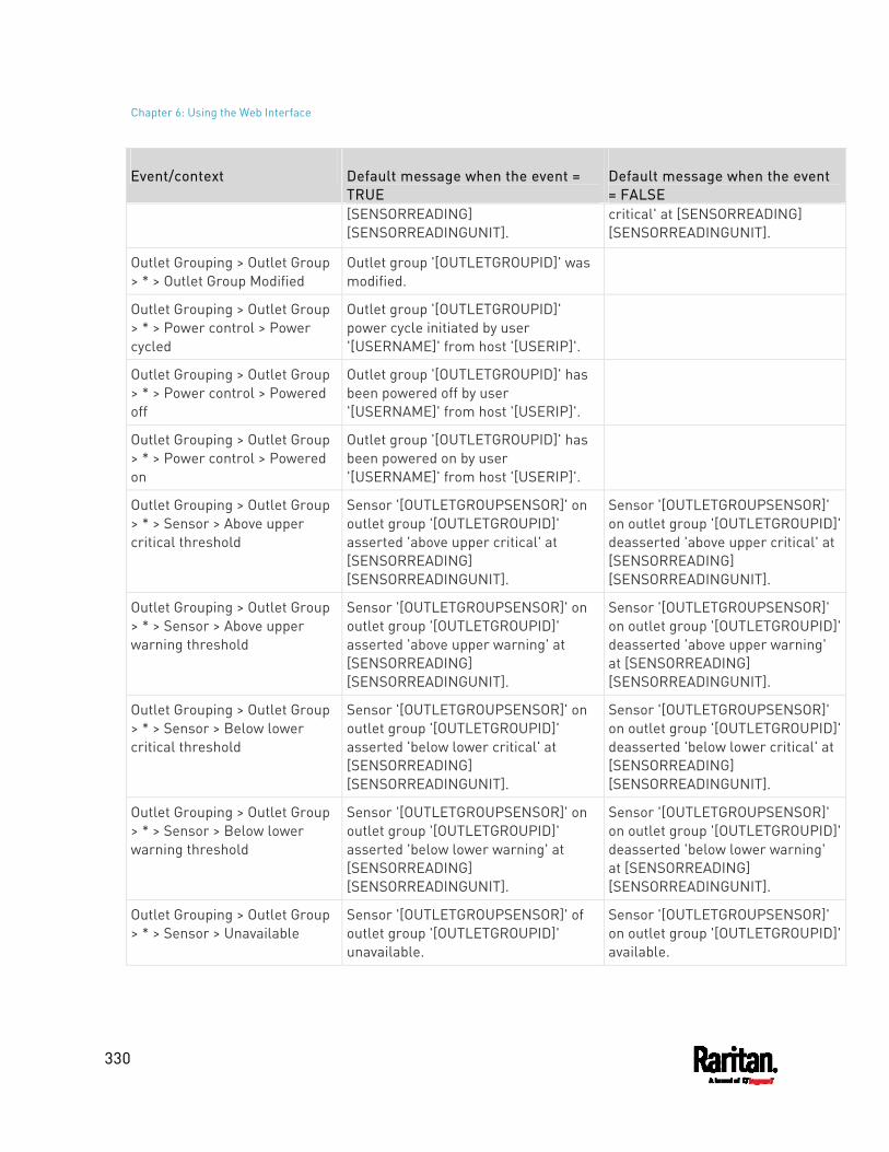
Chapter 6: Using the Web Interface
330
Event/context Default message when the event = TRUE
Default message when the event = FALSE
[SENSORREADING] [SENSORREADINGUNIT].
critical' at [SENSORREADING] [SENSORREADINGUNIT].
Outlet Grouping > Outlet Group > * > Outlet Group Modified
Outlet group '[OUTLETGROUPID]' was modified.
Outlet Grouping > Outlet Group > * > Power control > Power cycled
Outlet group '[OUTLETGROUPID]' power cycle initiated by user '[USERNAME]' from host '[USERIP]'.
Outlet Grouping > Outlet Group > * > Power control > Powered off
Outlet group '[OUTLETGROUPID]' has been powered off by user '[USERNAME]' from host '[USERIP]'.
Outlet Grouping > Outlet Group > * > Power control > Powered on
Outlet group '[OUTLETGROUPID]' has been powered on by user '[USERNAME]' from host '[USERIP]'.
Outlet Grouping > Outlet Group > * > Sensor > Above upper critical threshold
Sensor '[OUTLETGROUPSENSOR]' on outlet group '[OUTLETGROUPID]' asserted 'above upper critical' at [SENSORREADING] [SENSORREADINGUNIT].
Sensor '[OUTLETGROUPSENSOR]' on outlet group '[OUTLETGROUPID]' deasserted 'above upper critical' at [SENSORREADING] [SENSORREADINGUNIT].
Outlet Grouping > Outlet Group > * > Sensor > Above upper warning threshold
Sensor '[OUTLETGROUPSENSOR]' on outlet group '[OUTLETGROUPID]' asserted 'above upper warning' at [SENSORREADING] [SENSORREADINGUNIT].
Sensor '[OUTLETGROUPSENSOR]' on outlet group '[OUTLETGROUPID]' deasserted 'above upper warning' at [SENSORREADING] [SENSORREADINGUNIT].
Outlet Grouping > Outlet Group > * > Sensor > Below lower critical threshold
Sensor '[OUTLETGROUPSENSOR]' on outlet group '[OUTLETGROUPID]' asserted 'below lower critical' at [SENSORREADING] [SENSORREADINGUNIT].
Sensor '[OUTLETGROUPSENSOR]' on outlet group '[OUTLETGROUPID]' deasserted 'below lower critical' at [SENSORREADING] [SENSORREADINGUNIT].
Outlet Grouping > Outlet Group > * > Sensor > Below lower warning threshold
Sensor '[OUTLETGROUPSENSOR]' on outlet group '[OUTLETGROUPID]' asserted 'below lower warning' at [SENSORREADING] [SENSORREADINGUNIT].
Sensor '[OUTLETGROUPSENSOR]' on outlet group '[OUTLETGROUPID]' deasserted 'below lower warning' at [SENSORREADING] [SENSORREADINGUNIT].
Outlet Grouping > Outlet Group > * > Sensor > Unavailable
Sensor '[OUTLETGROUPSENSOR]' of outlet group '[OUTLETGROUPID]' unavailable.
Sensor '[OUTLETGROUPSENSOR]' on outlet group '[OUTLETGROUPID]' available.
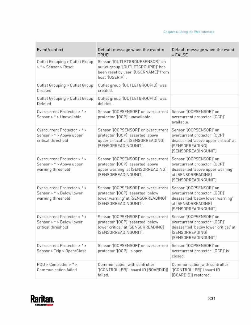
Chapter 6: Using the Web Interface
331
Event/context Default message when the event = TRUE
Default message when the event = FALSE
Outlet Grouping > Outlet Group > * > Sensor > Reset
Sensor '[OUTLETGROUPSENSOR]' on outlet group '[OUTLETGROUPID]' has been reset by user '[USERNAME]' from host '[USERIP]'.
Outlet Grouping > Outlet Group Created
Outlet group '[OUTLETGROUPID]' was created.
Outlet Grouping > Outlet Group Deleted
Outlet group '[OUTLETGROUPID]' was deleted.
Overcurrent Protector > * > Sensor > * > Unavailable
Sensor '[OCPSENSOR]' on overcurrent protector '[OCP]' unavailable.
Sensor '[OCPSENSOR]' on overcurrent protector '[OCP]' available.
Overcurrent Protector > * > Sensor > * > Above upper critical threshold
Sensor '[OCPSENSOR]' on overcurrent protector '[OCP]' asserted 'above upper critical' at [SENSORREADING] [SENSORREADINGUNIT].
Sensor '[OCPSENSOR]' on overcurrent protector '[OCP]' deasserted 'above upper critical' at [SENSORREADING] [SENSORREADINGUNIT].
Overcurrent Protector > * > Sensor > * > Above upper warning threshold
Sensor '[OCPSENSOR]' on overcurrent protector '[OCP]' asserted 'above upper warning' at [SENSORREADING] [SENSORREADINGUNIT].
Sensor '[OCPSENSOR]' on overcurrent protector '[OCP]' deasserted 'above upper warning' at [SENSORREADING] [SENSORREADINGUNIT].
Overcurrent Protector > * > Sensor > * > Below lower warning threshold
Sensor '[OCPSENSOR]' on overcurrent protector '[OCP]' asserted 'below lower warning' at [SENSORREADING] [SENSORREADINGUNIT].
Sensor '[OCPSENSOR]' on overcurrent protector '[OCP]' deasserted 'below lower warning' at [SENSORREADING] [SENSORREADINGUNIT].
Overcurrent Protector > * > Sensor > * > Below lower critical threshold
Sensor '[OCPSENSOR]' on overcurrent protector '[OCP]' asserted 'below lower critical' at [SENSORREADING] [SENSORREADINGUNIT].
Sensor '[OCPSENSOR]' on overcurrent protector '[OCP]' deasserted 'below lower critical' at [SENSORREADING] [SENSORREADINGUNIT].
Overcurrent Protector > * > Sensor > Trip > Open/Close
Sensor '[OCPSENSOR]' on overcurrent protector '[OCP]' is open.
Sensor '[OCPSENSOR]' on overcurrent protector '[OCP]' is closed.
PDU > Controller > * > Communication failed
Communication with controller '[CONTROLLER]' (board ID [BOARDID]) failed.
Communication with controller '[CONTROLLER]' (board ID [BOARDID]) restored.
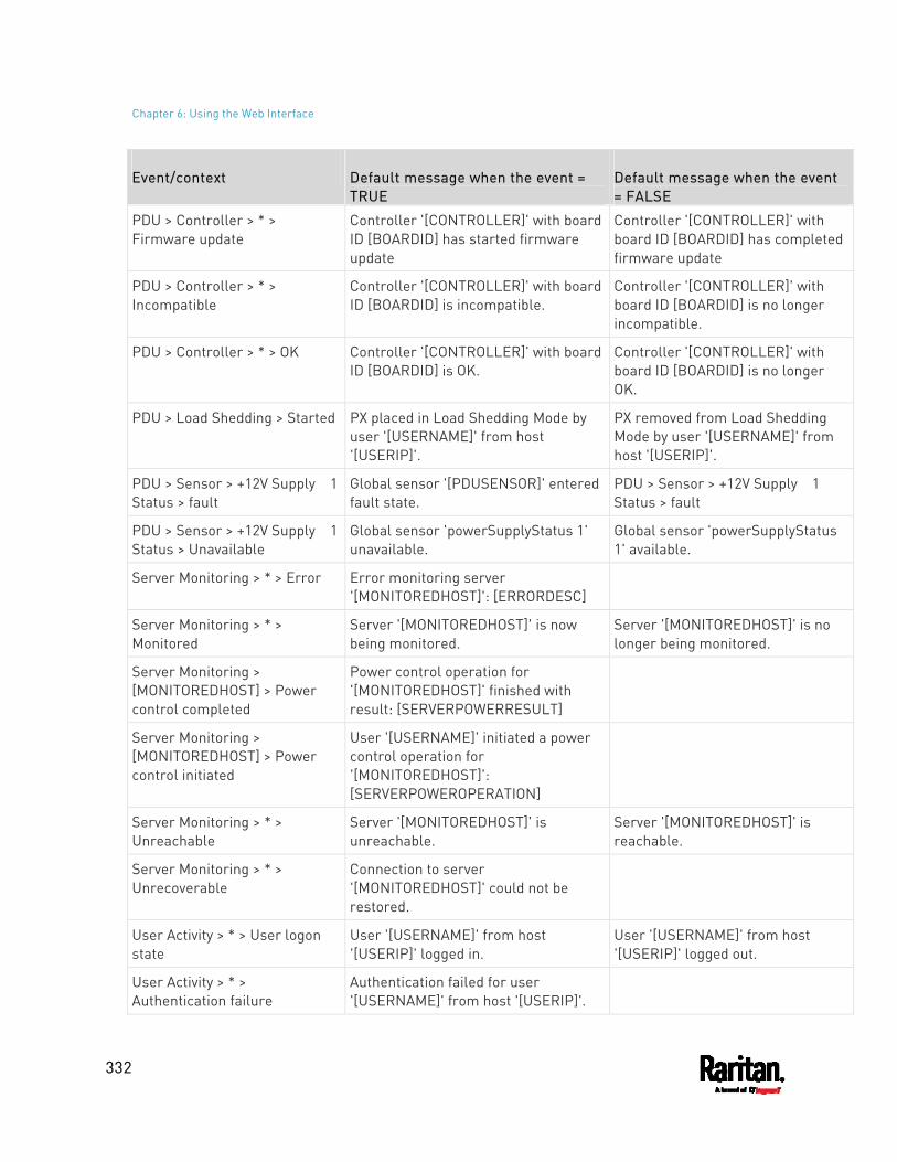
Chapter 6: Using the Web Interface
332
Event/context Default message when the event = TRUE
Default message when the event = FALSE
PDU > Controller > * > Firmware update
Controller '[CONTROLLER]' with board ID [BOARDID] has started firmware update
Controller '[CONTROLLER]' with board ID [BOARDID] has completed firmware update
PDU > Controller > * > Incompatible
Controller '[CONTROLLER]' with board ID [BOARDID] is incompatible.
Controller '[CONTROLLER]' with board ID [BOARDID] is no longer incompatible.
PDU > Controller > * > OK Controller '[CONTROLLER]' with board ID [BOARDID] is OK.
Controller '[CONTROLLER]' with board ID [BOARDID] is no longer OK.
PDU > Load Shedding > Started PX placed in Load Shedding Mode by user '[USERNAME]' from host '[USERIP]'.
PX removed from Load Shedding Mode by user '[USERNAME]' from host '[USERIP]'.
PDU > Sensor > +12V Supply 1 Status > fault
Global sensor '[PDUSENSOR]' entered fault state.
PDU > Sensor > +12V Supply 1 Status > fault
PDU > Sensor > +12V Supply 1 Status > Unavailable
Global sensor 'powerSupplyStatus 1' unavailable.
Global sensor 'powerSupplyStatus 1' available.
Server Monitoring > * > Error Error monitoring server '[MONITOREDHOST]': [ERRORDESC]
Server Monitoring > * > Monitored
Server '[MONITOREDHOST]' is now being monitored.
Server '[MONITOREDHOST]' is no longer being monitored.
Server Monitoring > [MONITOREDHOST] > Power control completed
Power control operation for '[MONITOREDHOST]' finished with result: [SERVERPOWERRESULT]
Server Monitoring > [MONITOREDHOST] > Power control initiated
User '[USERNAME]' initiated a power control operation for '[MONITOREDHOST]': [SERVERPOWEROPERATION]
Server Monitoring > * > Unreachable
Server '[MONITOREDHOST]' is unreachable.
Server '[MONITOREDHOST]' is reachable.
Server Monitoring > * > Unrecoverable
Connection to server '[MONITOREDHOST]' could not be restored.
User Activity > * > User logon state
User '[USERNAME]' from host '[USERIP]' logged in.
User '[USERNAME]' from host '[USERIP]' logged out.
User Activity > * > Authentication failure
Authentication failed for user '[USERNAME]' from host '[USERIP]'.
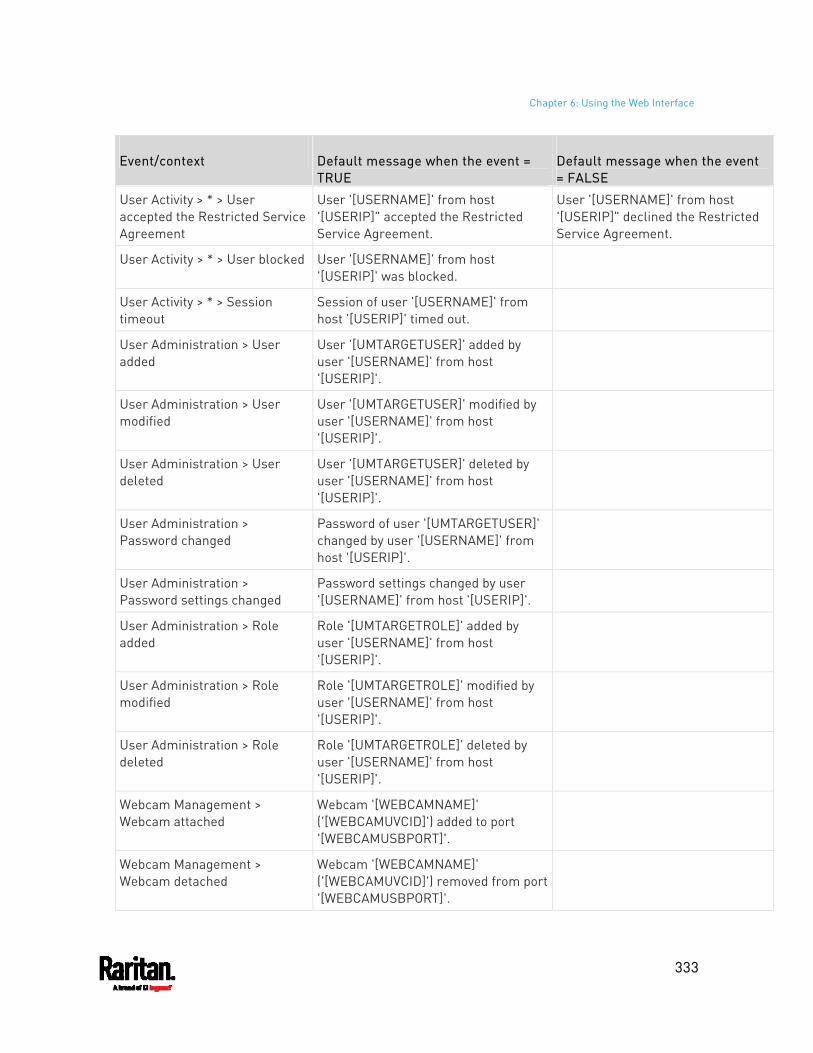
Chapter 6: Using the Web Interface
333
Event/context Default message when the event = TRUE
Default message when the event = FALSE
User Activity > * > User accepted the Restricted Service Agreement
User '[USERNAME]' from host '[USERIP]" accepted the Restricted Service Agreement.
User '[USERNAME]' from host '[USERIP]" declined the Restricted Service Agreement.
User Activity > * > User blocked User '[USERNAME]' from host '[USERIP]' was blocked.
User Activity > * > Session timeout
Session of user '[USERNAME]' from host '[USERIP]' timed out.
User Administration > User added
User '[UMTARGETUSER]' added by user '[USERNAME]' from host '[USERIP]'.
User Administration > User modified
User '[UMTARGETUSER]' modified by user '[USERNAME]' from host '[USERIP]'.
User Administration > User deleted
User '[UMTARGETUSER]' deleted by user '[USERNAME]' from host '[USERIP]'.
User Administration > Password changed
Password of user '[UMTARGETUSER]' changed by user '[USERNAME]' from host '[USERIP]'.
User Administration > Password settings changed
Password settings changed by user '[USERNAME]' from host '[USERIP]'.
User Administration > Role added
Role '[UMTARGETROLE]' added by user '[USERNAME]' from host '[USERIP]'.
User Administration > Role modified
Role '[UMTARGETROLE]' modified by user '[USERNAME]' from host '[USERIP]'.
User Administration > Role deleted
Role '[UMTARGETROLE]' deleted by user '[USERNAME]' from host '[USERIP]'.
Webcam Management > Webcam attached
Webcam '[WEBCAMNAME]' ('[WEBCAMUVCID]') added to port '[WEBCAMUSBPORT]'.
Webcam Management > Webcam detached
Webcam '[WEBCAMNAME]' ('[WEBCAMUVCID]') removed from port '[WEBCAMUSBPORT]'.
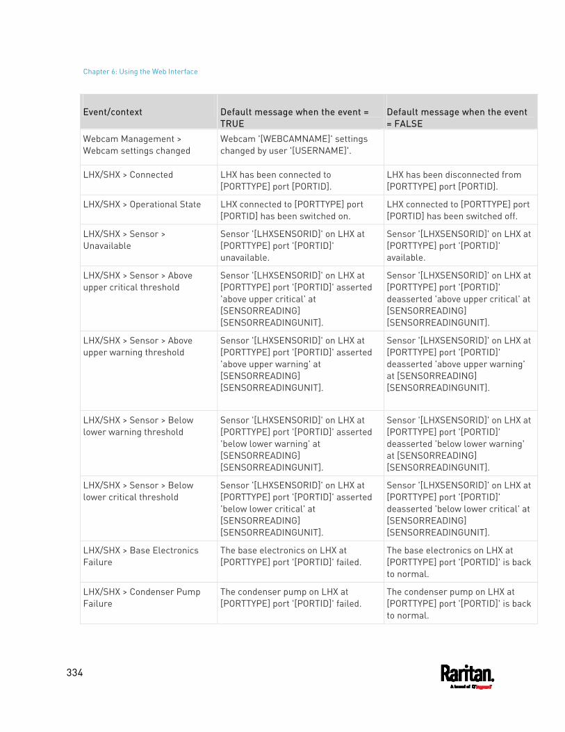
Chapter 6: Using the Web Interface
334
Event/context Default message when the event = TRUE
Default message when the event = FALSE
Webcam Management > Webcam settings changed
Webcam '[WEBCAMNAME]' settings changed by user '[USERNAME]'.
LHX/SHX > Connected LHX has been connected to [PORTTYPE] port [PORTID].
LHX has been disconnected from [PORTTYPE] port [PORTID].
LHX/SHX > Operational State LHX connected to [PORTTYPE] port [PORTID] has been switched on.
LHX connected to [PORTTYPE] port [PORTID] has been switched off.
LHX/SHX > Sensor > Unavailable
Sensor '[LHXSENSORID]' on LHX at [PORTTYPE] port '[PORTID]' unavailable.
Sensor '[LHXSENSORID]' on LHX at [PORTTYPE] port '[PORTID]' available.
LHX/SHX > Sensor > Above upper critical threshold
Sensor '[LHXSENSORID]' on LHX at [PORTTYPE] port '[PORTID]' asserted 'above upper critical' at [SENSORREADING] [SENSORREADINGUNIT].
Sensor '[LHXSENSORID]' on LHX at [PORTTYPE] port '[PORTID]' deasserted 'above upper critical' at [SENSORREADING] [SENSORREADINGUNIT].
LHX/SHX > Sensor > Above upper warning threshold
Sensor '[LHXSENSORID]' on LHX at [PORTTYPE] port '[PORTID]' asserted 'above upper warning' at [SENSORREADING] [SENSORREADINGUNIT].
Sensor '[LHXSENSORID]' on LHX at [PORTTYPE] port '[PORTID]' deasserted 'above upper warning' at [SENSORREADING] [SENSORREADINGUNIT].
LHX/SHX > Sensor > Below lower warning threshold
Sensor '[LHXSENSORID]' on LHX at [PORTTYPE] port '[PORTID]' asserted 'below lower warning' at [SENSORREADING] [SENSORREADINGUNIT].
Sensor '[LHXSENSORID]' on LHX at [PORTTYPE] port '[PORTID]' deasserted 'below lower warning' at [SENSORREADING] [SENSORREADINGUNIT].
LHX/SHX > Sensor > Below lower critical threshold
Sensor '[LHXSENSORID]' on LHX at [PORTTYPE] port '[PORTID]' asserted 'below lower critical' at [SENSORREADING] [SENSORREADINGUNIT].
Sensor '[LHXSENSORID]' on LHX at [PORTTYPE] port '[PORTID]' deasserted 'below lower critical' at [SENSORREADING] [SENSORREADINGUNIT].
LHX/SHX > Base Electronics Failure
The base electronics on LHX at [PORTTYPE] port '[PORTID]' failed.
The base electronics on LHX at [PORTTYPE] port '[PORTID]' is back to normal.
LHX/SHX > Condenser Pump Failure
The condenser pump on LHX at [PORTTYPE] port '[PORTID]' failed.
The condenser pump on LHX at [PORTTYPE] port '[PORTID]' is back to normal.
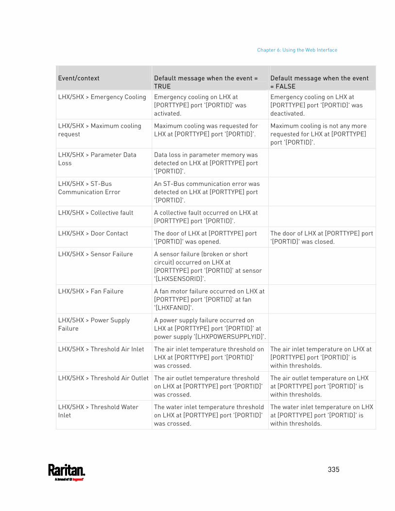
Chapter 6: Using the Web Interface
335
Event/context Default message when the event = TRUE
Default message when the event = FALSE
LHX/SHX > Emergency Cooling Emergency cooling on LHX at [PORTTYPE] port '[PORTID]' was activated.
Emergency cooling on LHX at [PORTTYPE] port '[PORTID]' was deactivated.
LHX/SHX > Maximum cooling request
Maximum cooling was requested for LHX at [PORTTYPE] port '[PORTID]'.
Maximum cooling is not any more requested for LHX at [PORTTYPE] port '[PORTID]'.
LHX/SHX > Parameter Data Loss
Data loss in parameter memory was detected on LHX at [PORTTYPE] port '[PORTID]'.
LHX/SHX > ST-Bus Communication Error
An ST-Bus communication error was detected on LHX at [PORTTYPE] port '[PORTID]'.
LHX/SHX > Collective fault A collective fault occurred on LHX at [PORTTYPE] port '[PORTID]'.
LHX/SHX > Door Contact The door of LHX at [PORTTYPE] port '[PORTID]' was opened.
The door of LHX at [PORTTYPE] port '[PORTID]' was closed.
LHX/SHX > Sensor Failure A sensor failure (broken or short circuit) occurred on LHX at [PORTTYPE] port '[PORTID]' at sensor '[LHXSENSORID]'.
LHX/SHX > Fan Failure A fan motor failure occurred on LHX at [PORTTYPE] port '[PORTID]' at fan '[LHXFANID]'.
LHX/SHX > Power Supply Failure
A power supply failure occurred on LHX at [PORTTYPE] port '[PORTID]' at power supply '[LHXPOWERSUPPLYID]'.
LHX/SHX > Threshold Air Inlet The air inlet temperature threshold on LHX at [PORTTYPE] port '[PORTID]' was crossed.
The air inlet temperature on LHX at [PORTTYPE] port '[PORTID]' is within thresholds.
LHX/SHX > Threshold Air Outlet The air outlet temperature threshold on LHX at [PORTTYPE] port '[PORTID]' was crossed.
The air outlet temperature on LHX at [PORTTYPE] port '[PORTID]' is within thresholds.
LHX/SHX > Threshold Water Inlet
The water inlet temperature threshold on LHX at [PORTTYPE] port '[PORTID]' was crossed.
The water inlet temperature on LHX at [PORTTYPE] port '[PORTID]' is within thresholds.
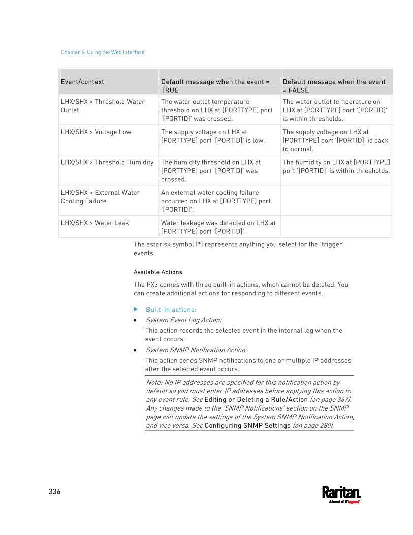
Chapter 6: Using the Web Interface
336
Event/context Default message when the event = TRUE
Default message when the event = FALSE
LHX/SHX > Threshold Water Outlet
The water outlet temperature threshold on LHX at [PORTTYPE] port '[PORTID]' was crossed.
The water outlet temperature on LHX at [PORTTYPE] port '[PORTID]' is within thresholds.
LHX/SHX > Voltage Low The supply voltage on LHX at [PORTTYPE] port '[PORTID]' is low.
The supply voltage on LHX at [PORTTYPE] port '[PORTID]' is back to normal.
LHX/SHX > Threshold Humidity The humidity threshold on LHX at [PORTTYPE] port '[PORTID]' was crossed.
The humidity on LHX at [PORTTYPE] port '[PORTID]' is within thresholds.
LHX/SHX > External Water Cooling Failure
An external water cooling failure occurred on LHX at [PORTTYPE] port '[PORTID]'.
LHX/SHX > Water Leak Water leakage was detected on LHX at [PORTTYPE] port '[PORTID]'.
The asterisk symbol (*) represents anything you select for the 'trigger' events.
Available Actions
The PX3 comes with three built-in actions, which cannot be deleted. You can create additional actions for responding to different events.
Built-in actions: System Event Log Action:
This action records the selected event in the internal log when the event occurs.
System SNMP Notification Action: This action sends SNMP notifications to one or multiple IP addresses after the selected event occurs.
Note: No IP addresses are specified for this notification action by default so you must enter IP addresses before applying this action to any event rule. See Editing or Deleting a Rule/Action (on page 367). Any changes made to the 'SNMP Notifications' section on the SNMP page will update the settings of the System SNMP Notification Action, and vice versa. See Configuring SNMP Settings (on page 280).
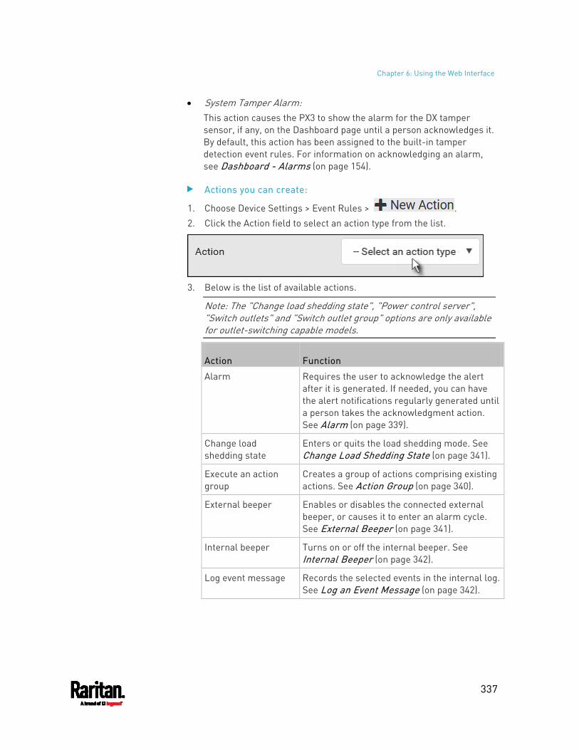
Chapter 6: Using the Web Interface
337
System Tamper Alarm: This action causes the PX3 to show the alarm for the DX tamper sensor, if any, on the Dashboard page until a person acknowledges it. By default, this action has been assigned to the built-in tamper detection event rules. For information on acknowledging an alarm, see Dashboard - Alarms (on page 154).
Actions you can create:
1. Choose Device Settings > Event Rules > . 2. Click the Action field to select an action type from the list.
3. Below is the list of available actions.
Note: The "Change load shedding state", "Power control server", "Switch outlets" and "Switch outlet group" options are only available for outlet-switching capable models.
Action Function
Alarm Requires the user to acknowledge the alert after it is generated. If needed, you can have the alert notifications regularly generated until a person takes the acknowledgment action. See Alarm (on page 339).
Change load shedding state
Enters or quits the load shedding mode. See Change Load Shedding State (on page 341).
Execute an action group
Creates a group of actions comprising existing actions. See Action Group (on page 340).
External beeper Enables or disables the connected external beeper, or causes it to enter an alarm cycle. See External Beeper (on page 341).
Internal beeper Turns on or off the internal beeper. See Internal Beeper (on page 342).
Log event message Records the selected events in the internal log. See Log an Event Message (on page 342).
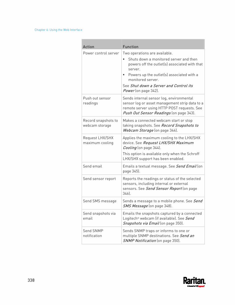
Chapter 6: Using the Web Interface
338
Action Function
Power control server Two operations are available. Shuts down a monitored server and then
powers off the outlet(s) associated with that server.
Powers up the outlet(s) associated with a monitored server.
See Shut down a Server and Control its Power (on page 342).
Push out sensor readings
Sends internal sensor log, environmental sensor log or asset management strip data to a remote server using HTTP POST requests. See Push Out Sensor Readings (on page 343).
Record snapshots to webcam storage
Makes a connected webcam start or stop taking snapshots. See Record Snapshots to Webcam Storage (on page 344).
Request LHX/SHX maximum cooling
Applies the maximum cooling to the LHX/SHX device. See Request LHX/SHX Maximum Cooling (on page 344). This option is available only when the Schroff LHX/SHX support has been enabled.
Send email Emails a textual message. See Send Email (on page 345).
Send sensor report Reports the readings or status of the selected sensors, including internal or external sensors. See Send Sensor Report (on page 346).
Send SMS message Sends a message to a mobile phone. See Send SMS Message (on page 348).
Send snapshots via email
Emails the snapshots captured by a connected Logitech® webcam (if available). See Send Snapshots via Email (on page 350).
Send SNMP notification
Sends SNMP traps or informs to one or multiple SNMP destinations. See Send an SNMP Notification (on page 350).
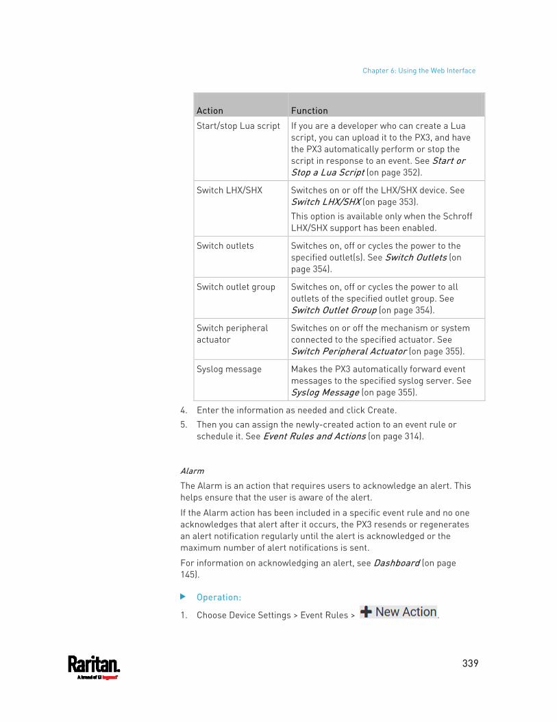
Chapter 6: Using the Web Interface
339
Action Function
Start/stop Lua script If you are a developer who can create a Lua script, you can upload it to the PX3, and have the PX3 automatically perform or stop the script in response to an event. See Start or Stop a Lua Script (on page 352).
Switch LHX/SHX Switches on or off the LHX/SHX device. See Switch LHX/SHX (on page 353). This option is available only when the Schroff LHX/SHX support has been enabled.
Switch outlets Switches on, off or cycles the power to the specified outlet(s). See Switch Outlets (on page 354).
Switch outlet group Switches on, off or cycles the power to all outlets of the specified outlet group. See Switch Outlet Group (on page 354).
Switch peripheral actuator
Switches on or off the mechanism or system connected to the specified actuator. See Switch Peripheral Actuator (on page 355).
Syslog message Makes the PX3 automatically forward event messages to the specified syslog server. See Syslog Message (on page 355).
4. Enter the information as needed and click Create. 5. Then you can assign the newly-created action to an event rule or
schedule it. See Event Rules and Actions (on page 314).
Alarm
The Alarm is an action that requires users to acknowledge an alert. This helps ensure that the user is aware of the alert.
If the Alarm action has been included in a specific event rule and no one acknowledges that alert after it occurs, the PX3 resends or regenerates an alert notification regularly until the alert is acknowledged or the maximum number of alert notifications is sent.
For information on acknowledging an alert, see Dashboard (on page 145).
Operation:
1. Choose Device Settings > Event Rules > .
Chapter 6: Using the Web Interface
340
2. Select Alarm from the Action list. 3. In the Alarm Notifications list box, specify one or multiple ways to
issue the alert notifications. Available methods vary, depending on how many notification-based actions have been created. Notification-based action types include:
External beeper Syslog message Send email Send SMS message Internal beeper If no appropriate actions are available, create them first.
a. To select any methods, select them one by one in the Available field. To add all available methods, simply click Select All.
b. To delete any methods, click a method's in the Selected field. To remove all methods, simply click Deselect All.
4. To enable the notification-resending feature, select the "Enable Re-scheduling of Alarm Notifications" checkbox.
5. In the "Re-scheduling Period" field, specify the time interval (in minutes) at which the alert notification is resent or regenerated regularly.
6. In the "Re-scheduling Limit" field, specify the maximum number of times the alert notification is resent. Values range from 1 to infinite.
7. (Optional) You can instruct the PX3 to send the acknowledgment notification after the alarm is acknowledged in the Acknowledgment Notifications field. Available methods are identical to those for generating alarm notifications. a. In the Available field, select desired methods one by one, or click
Select All. See step 3 for details.
b. In the Selected field, click any method's to remove unnecessary ones, or click Deselect All.
Action Group
You can create an action group that performs up to 32 actions. After creating such an action group, you can easily assign this set of actions to any event rule rather than selecting all needed actions one by one per rule.
If the needed action is not available yet, create it first. See Available Actions (on page 336).
Chapter 6: Using the Web Interface
341
Operation:
1. Choose Device Settings > Event Rules > . 2. Select "Execute an action group" from the Action list. 3. To select any action(s), select them one by one from the Available
Actions list. To select all available actions, click Select All.
4. To remove any action(s) from the Selected Actions field, click that action's . To remove all actions, click Deselect All.
Change Load Shedding State
The "Change load shedding state" action is available only when your PX3 is able to control outlet power. Use this action to activate or deactivate the load shedding mode for responding to a specific event. For additional information, see Load Shedding Mode (on page 176).
Operation:
1. Choose Device Settings > Event Rules > . 2. Select "Change load shedding state" from the Action list. 3. In the Operation field, select either one below:
Start Load Shedding: Enters the load shedding mode when the specified event occurs.
Stop Load Shedding: Quits the load shedding mode when the specified event occurs.
External Beeper
If an external beeper is connected to the PX3, the PX3 can change the beeper's behavior or status to respond to a certain event.
To control the connected external beeper:
1. Choose Device Settings > Event Rules > . 2. Select "External beeper" from the Action list. 3. In the Beeper Port field, select the port where the external beeper is
connected. This port is the FEATURE port. 4. In the Beeper Action field, select an action for the external beeper to
carry out.
Chapter 6: Using the Web Interface
342
Alarm: Causes the external beeper to sound an alarm cycle every 20 seconds - stays on for 0.7 seconds and then off for 19.3 seconds.
On: Turns on the external beeper so that it buzzes continuously. Off: Turns off the external beeper so that it stops buzzing.
Warning: If you create an event rule for the external beeper but disconnect it when an event causes it to beep, the beeper no longer beeps after it is re-connected even though the event triggering the beeping action remains asserted.
Internal Beeper
You can have the built-in beeper of the PX3 turned on or off when a certain event occurs.
Operation:
1. Choose Device Settings > Event Rules > . 2. Select "Internal beeper" from the Action list. 3. Select an option from the Operation field.
Turn Beeper On: Turns on the internal beeper to make it buzz. Turn Beeper Off: Turns off the internal beeper to make it stop
buzzing.
Log an Event Message
The option "Log event message" records the selected events in the internal log.
The default log message generated for each type of event is available in the section titled Default Log Messages (on page 321).
Shut down a Server and Control its Power
The "Power control server" action is available only when your PX3 is outlet-switching capable.
You can configure the PX3 to shut down a specific server and then turn off its outlet(s), or turn on that server's outlet(s) after a certain event occurs.
The only restriction is a server must be one of the servers being monitored by your PX3 and the same PX3 supplies power to it. To have any server monitored, see Monitoring Server Accessibility (on page 384).
Chapter 6: Using the Web Interface
343
Tip: If the server has multiple power cords, make sure all of its power cords are connected to the same PX3 and you have created an outlet group for controlling all outlets simultaneously. See Outlet Groups (on page 186).
Operation:
1. Choose Device Settings > Event Rules > . 2. Select "Power control server" from the Action list. 3. In the Operation field, select an action for the server.
Power up: Turns on the outlet or outlet group associated with the selected server.
Graceful shutdown: Shuts down the selected server first and then turn off its associated outlet or outlet group.
4. Select the server you want in the Server field. If PX3 cannot power control any server, a message "Power
control not configured" is shown in the end of the server's host name or IP address.
Push Out Sensor Readings
You can configure the PX3 to push sensor log to a remote server after a certain event occurs, including logs of internal sensors, environmental sensors and actuators.
If you have connected Raritan's asset strips to the PX3, you can also configure the PX3 to push the data to a server.
Before creating this action, make sure that you have properly defined the destination servers and the data to be sent on the Data Push page. See Configuring Data Push Settings (on page 376).
Tip: To send the data at a regular interval, schedule this action. See Scheduling an Action (on page 356). Note that the "Asset management log" is generated only when there are changes made to any asset strips or asset tags, such as connection or disconnection events.
Operation:
1. Choose Device Settings > Event Rules > . 2. Select "Push out sensor readings" from the Action list. 3. Select a server or host which receives the data in the Destination
field. If the desired destination is not available yet, go to the Data Push
page to specify it.
Chapter 6: Using the Web Interface
344
Record Snapshots to Webcam Storage
This option allows you to define an action that starts or stops a specific webcam from taking snapshots.
Per default the snapshots are stored on the PX3. See Viewing and Managing Locally-Saved Snapshots (on page 439).
It is recommended to specify a remote server to store as many snapshots as possible. See Changing Storage Settings (on page 441).
Operation:
1. Choose Device Settings > Event Rules > . 2. Select "Record snapshots to webcam storage" from the Action list. 3. Select a webcam in the Webcam field. 4. Select the action to perform - "Start recording" or "Stop recording."
If "Start recording" is selected, adjust the values of the following: Number of Snapshots - the number of snapshots to be taken
when the event occurs. The maximum amount of snapshots that can be stored on the PX3 is 10. If you set it for a number greater than 10 and the storage location is on the PX3, after the 10th snapshot is taken and stored, the oldest snapshots are overwritten. Storing snapshots on a remote server does not have such a limitation.
Time Before First Snapshot - the amount of time in seconds between when the event is triggered and the webcam begins taking snapshots.
Time Between Snapshots - the amount of time in seconds between when each snapshot is taken.
Request LHX/SHX Maximum Cooling
If Schroff LHX/SHX Support is enabled, the LHX/SHX-related actions will be available. See Miscellaneous (on page 402).
The "Request LHX/SHX Maximum Cooling" action applies the maximum cooling to the SHX-30 device only. The LHX-20 and LHX-40 devices do not support this feature.
In the maximum cooling mode, an SHX-30 device runs at 100% fan speed and the cold water valve is open 100%.
Operation:
1. Choose Device Settings > Event Rules > . 2. Select "Request LHX/SHX Maximum Cooling" from the Action list.
Chapter 6: Using the Web Interface
345
3. In the Available LHX/SHX field, select the desired SHX-30 device one by one, or click Select All.
4. To remove any SHX-30 device from the Selected LHX/SHX field, click that device's or click Deselect All.
Send Email
You can configure emails to be sent when an event occurs and can customize the message.
Messages consist of a combination of free text and PX3 placeholders. The placeholders represent information which is pulled from the PX3 and inserted into the message.
For example:
[USERNAME] logged into the device on [TIMESTAMP]
translates to
Mary logged into the device on 2012-January-30 21:00
For a list and definition of available variables, see Placeholders for Custom Messages (on page 363).
Operation:
1. Choose Device Settings > Event Rules > . 2. Select "Send email" from the Action list. 3. In the "Recipient Email Addresses" field, specify the email
address(es) of the recipient(s). Use a comma to separate multiple email addresses.
4. By default, the SMTP server specified on the SMTP Server page will be the SMTP server for performing this action. To use a different SMTP server, select the "Use custom settings" radio button. The fields for customized SMTP settings appear. For information on each field, see Configuring SMTP Settings (on page 282). Default messages are sent based on the event. For a list of default log messages and events that trigger them, see Default Log Messages (on page 321).
5. If needed, select the Use Custom Log Message checkbox, and then create a custom message up to 1024 characters in the provided field.
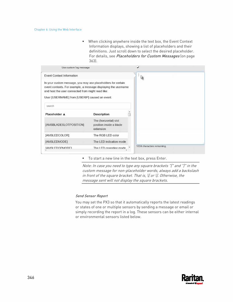
Chapter 6: Using the Web Interface
346
When clicking anywhere inside the text box, the Event Context Information displays, showing a list of placeholders and their definitions. Just scroll down to select the desired placeholder. For details, see Placeholders for Custom Messages (on page 363).
To start a new line in the text box, press Enter.
Note: In case you need to type any square brackets "[" and "]" in the custom message for non-placeholder words, always add a backslash in front of the square bracket. That is, \[ or \]. Otherwise, the message sent will not display the square brackets.
Send Sensor Report
You may set the PX3 so that it automatically reports the latest readings or states of one or multiple sensors by sending a message or email or simply recording the report in a log. These sensors can be either internal or environmental sensors listed below.
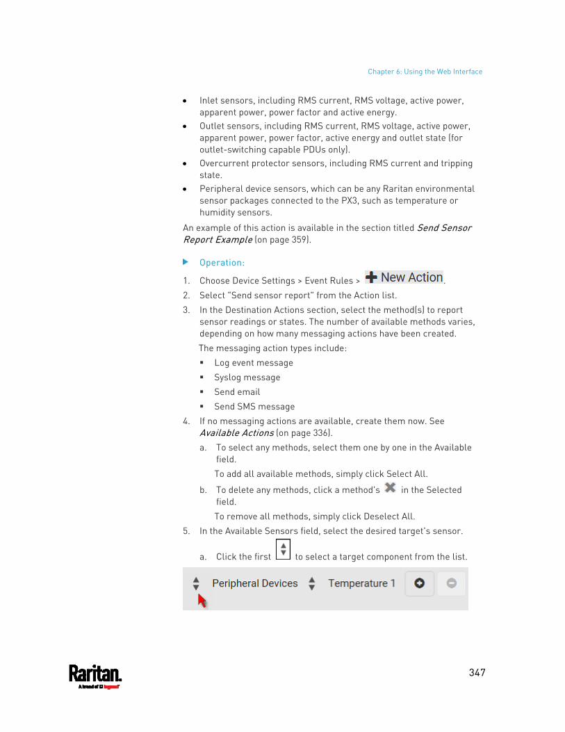
Chapter 6: Using the Web Interface
347
Inlet sensors, including RMS current, RMS voltage, active power, apparent power, power factor and active energy.
Outlet sensors, including RMS current, RMS voltage, active power, apparent power, power factor, active energy and outlet state (for outlet-switching capable PDUs only).
Overcurrent protector sensors, including RMS current and tripping state.
Peripheral device sensors, which can be any Raritan environmental sensor packages connected to the PX3, such as temperature or humidity sensors.
An example of this action is available in the section titled Send Sensor Report Example (on page 359).
Operation:
1. Choose Device Settings > Event Rules > . 2. Select "Send sensor report" from the Action list. 3. In the Destination Actions section, select the method(s) to report
sensor readings or states. The number of available methods varies, depending on how many messaging actions have been created. The messaging action types include: Log event message Syslog message Send email Send SMS message
4. If no messaging actions are available, create them now. See Available Actions (on page 336). a. To select any methods, select them one by one in the Available
field. To add all available methods, simply click Select All.
b. To delete any methods, click a method's in the Selected field. To remove all methods, simply click Deselect All.
5. In the Available Sensors field, select the desired target's sensor.
a. Click the first to select a target component from the list.
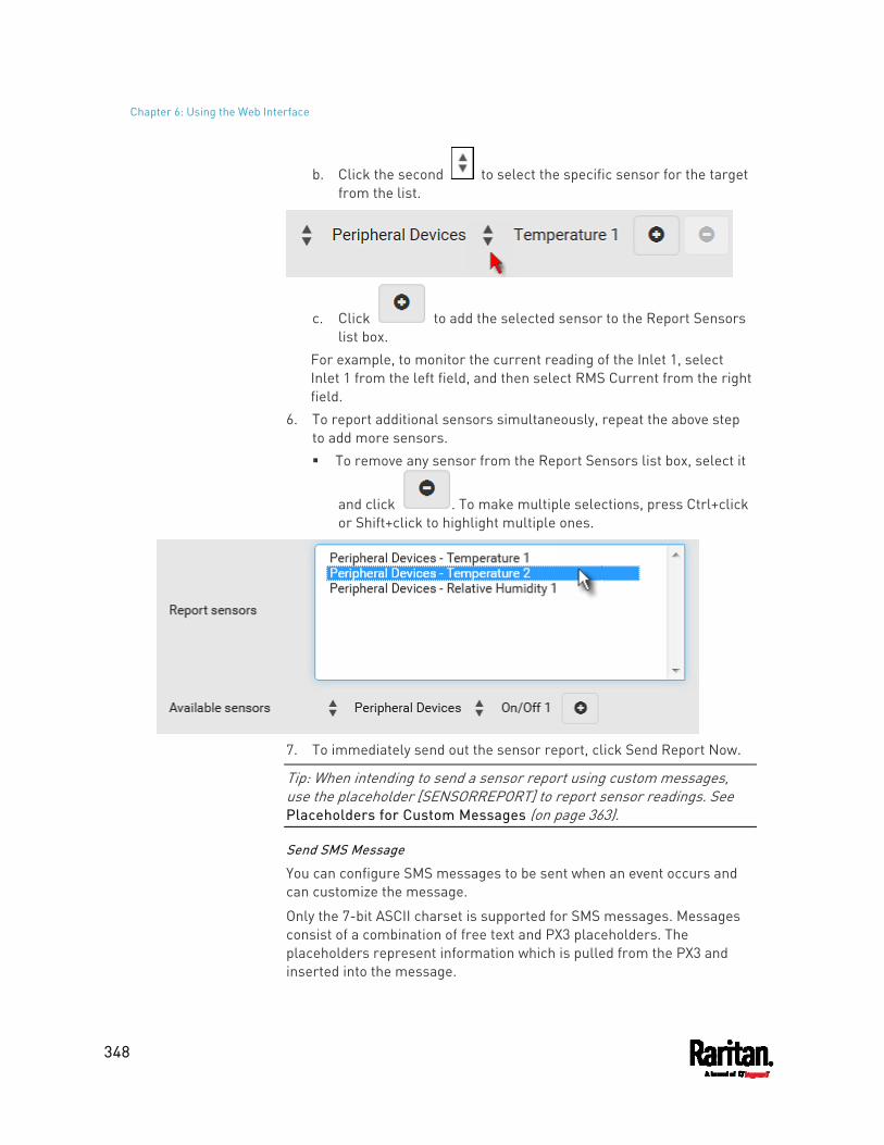
Chapter 6: Using the Web Interface
348
b. Click the second to select the specific sensor for the target from the list.
c. Click to add the selected sensor to the Report Sensors list box.
For example, to monitor the current reading of the Inlet 1, select Inlet 1 from the left field, and then select RMS Current from the right field.
6. To report additional sensors simultaneously, repeat the above step to add more sensors. To remove any sensor from the Report Sensors list box, select it
and click . To make multiple selections, press Ctrl+click or Shift+click to highlight multiple ones.
7. To immediately send out the sensor report, click Send Report Now.
Tip: When intending to send a sensor report using custom messages, use the placeholder [SENSORREPORT] to report sensor readings. See Placeholders for Custom Messages (on page 363).
Send SMS Message
You can configure SMS messages to be sent when an event occurs and can customize the message.
Only the 7-bit ASCII charset is supported for SMS messages. Messages consist of a combination of free text and PX3 placeholders. The placeholders represent information which is pulled from the PX3 and inserted into the message.
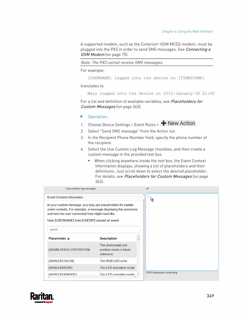
Chapter 6: Using the Web Interface
349
A supported modem, such as the Cinterion® GSM MC52i modem, must be plugged into the PX3 in order to send SMS messages. See Connecting a GSM Modem (on page 75).
Note: The PX3 cannot receive SMS messages.
For example:
[USERNAME] logged into the device on [TIMESTAMP]
translates to
Mary logged into the device on 2012-January-30 21:00
For a list and definition of available variables, see Placeholders for Custom Messages (on page 363).
Operation:
1. Choose Device Settings > Event Rules > . 2. Select "Send SMS message" from the Action list. 3. In the Recipient Phone Number field, specify the phone number of
the recipient. 4. Select the Use Custom Log Message checkbox, and then create a
custom message in the provided text box. When clicking anywhere inside the text box, the Event Context
Information displays, showing a list of placeholders and their definitions. Just scroll down to select the desired placeholder. For details, see Placeholders for Custom Messages (on page 363).
Chapter 6: Using the Web Interface
350
To start a new line in the text box, press Enter.
Note: In case you need to type any square brackets "[" and "]" in the custom message for non-placeholder words, always add a backslash in front of the square bracket. That is, \[ or \]. Otherwise, the message sent will not display the square brackets.
Send Snapshots via Email
This option notifies one or multiple persons for the selected events by emailing snapshots or videos captured by a connected Logitech® webcam.
Operation:
1. Choose Device Settings > Event Rules > . 2. Select "Send snapshots via email" from the Action list. 3. In the "Recipient Email Addresses" field, specify the email
address(es) of the recipient(s). Use a comma to separate multiple email addresses.
4. By default, the SMTP server specified on the SMTP Server page will be the SMTP server for performing this action. To use a different SMTP server, select the "Use custom SMTP Server" checkbox. The fields for customized SMTP settings appear. For information on each field, see Configuring SMTP Settings (on page 282).
5. Select the webcam that is capturing the images you want sent in the email.
6. Adjust the values of the following: Number of Snapshots - the number of snapshots to be taken
when the event occurs. For example, you can specify 10 images be taken once the event triggers the action.
Snapshots per Mail - the number of snapshots to be sent at one time in the email.
Time Before First Snapshot - the amount of time in seconds between when the event is triggered and the webcam begins taking snapshots.
Time Between Snapshots - the amount of time in seconds between when each snapshot is taken.
Send an SNMP Notification
This option sends an SNMP notification to one or multiple SNMP destinations.
Chapter 6: Using the Web Interface
351
Operation:
1. Choose Device Settings > Event Rules > . 2. Select "Send SNMP notification" from the Action list. 3. Select the type of SNMP notification. See either procedure below
according to your selection.
To send SNMP v2c notifications: 1. In the Notification Type field, select SNMPv2c Trap or SNMPv2c
Inform. 2. For SNMP INFORM communications, leave the resend settings at
their default or do the following: a. In the Timeout field, specify the interval of time, in seconds, after
which a new inform communication is resent if the first is not received. For example, resend a new inform communication once every 3 seconds.
b. In the Number of Retries field, specify the number of times you want to resend the inform communication if it fails. For example, inform communications are resent up to 5 times when the initial communication fails.
3. In the Host fields, enter the IP address of the device(s) you want to access. This is the address to which notifications are sent by the SNMP system agent.
4. In the Port fields, enter the port number used to access the device(s).
5. In the Community fields, enter the SNMP community string to access the device(s). The community is the group representing the PX3 and all SNMP management stations.
Tip: An SNMP v2c notification action permits only a maximum of three SNMP destinations. To assign more than three SNMP destinations to a specific rule, first create several SNMP v2c notification actions, each of which contains completely different SNMP destinations, and then add all of these SNMP v2c notification actions to the same rule.
To send SNMP v3 notifications: 1. In the Notification Type field, select SNMPv3 Trap or SNMPv3 Inform. 2. For SNMP TRAPs, the engine ID is prepopulated. 3. For SNMP INFORM communications, leave the resend settings at
their default or do the following:
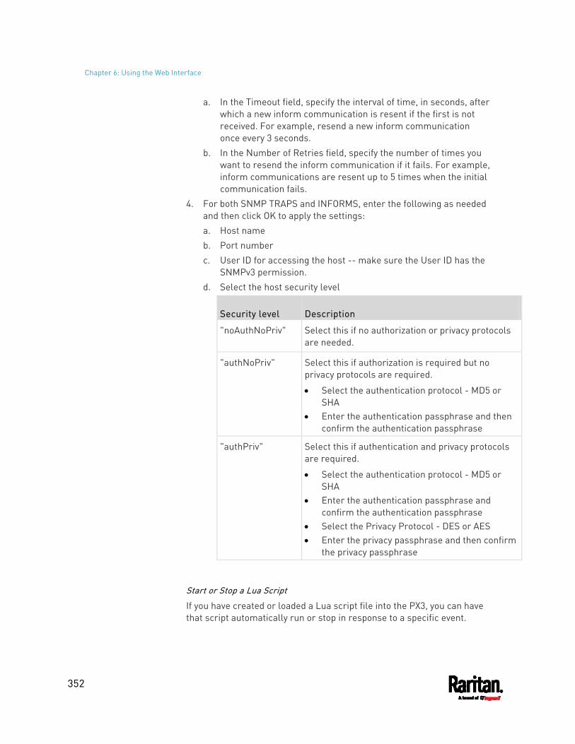
Chapter 6: Using the Web Interface
352
a. In the Timeout field, specify the interval of time, in seconds, after which a new inform communication is resent if the first is not received. For example, resend a new inform communication once every 3 seconds.
b. In the Number of Retries field, specify the number of times you want to resend the inform communication if it fails. For example, inform communications are resent up to 5 times when the initial communication fails.
4. For both SNMP TRAPS and INFORMS, enter the following as needed and then click OK to apply the settings: a. Host name b. Port number c. User ID for accessing the host -- make sure the User ID has the
SNMPv3 permission. d. Select the host security level
Security level Description
"noAuthNoPriv" Select this if no authorization or privacy protocols are needed.
"authNoPriv" Select this if authorization is required but no privacy protocols are required.
Select the authentication protocol - MD5 or SHA
Enter the authentication passphrase and then confirm the authentication passphrase
"authPriv" Select this if authentication and privacy protocols are required.
Select the authentication protocol - MD5 or SHA
Enter the authentication passphrase and confirm the authentication passphrase
Select the Privacy Protocol - DES or AES Enter the privacy passphrase and then confirm
the privacy passphrase
Start or Stop a Lua Script
If you have created or loaded a Lua script file into the PX3, you can have that script automatically run or stop in response to a specific event.
Chapter 6: Using the Web Interface
353
For instructions on creating or loading a Lua script into this product, see Lua Scripts (on page 396).
To automatically start or stop a Lua script:
1. Choose Device Settings > Event Rules > . 2. Select "Start/stop Lua script" from the Action list. 3. In the Operation field, select Start Script or Stop Script. 4. In the Script field, select the script that you want it to be started or
stopped when an event occurs. No script is available if you have not created or loaded it into the
PX3. 5. To apply different arguments than the default, do the following. Note
that the newly-added arguments will override this script's default arguments.
a. Click . b. Type the key and value. c. Repeat the same steps to enter more arguments as needed.
To remove any existing argument, click adjacent to it.
Switch LHX/SHX
If Schroff LHX/SHX Support is enabled, the LHX/SHX-related actions will be available. See Miscellaneous (on page 402).
Use this action to switch the LHX/SHX on or off when, for example, temperature thresholds are reached.
Operation:
1. Choose Device Settings > Event Rules > . 2. Select "Switch LHX/SHX" from the Action list. 3. In the Operation field, select Turn LHX/SHX On or Turn LHX/SHX Off. 4. In the Available LHX/SHX field, select the LHX/SHX device to be
turned on or off. To select all available LHX/SHX devices, click Select All. To remove any LHX/SHX device from the Selected LHX/SHX field, click that device's . To remove all devices, click Deselect All.
Chapter 6: Using the Web Interface
354
Switch Outlet Group
The "Switch outlet group" action is available only when your PX3 is outlet-switching capable. This action turns on, off or power cycles a specific outlet group.
Operation:
1. Choose Device Settings > Event Rules > . 2. Select "Switch outlet group" from the Action list. 3. To specify the outlet group where this action will be applied, select it
from the 'Group to switch' list. 4. In the Operation field, select an operation for the selected outlet
group. Turn on all outlets in group: Turns on the selected outlet group. Turn off all outlets in group: Turns off the selected outlet group. Cycle all outlets in group: Cycles power to the selected outlet
group.
Switch Outlets
The "Switch outlets" action is available only when your PX3 is outlet-switching capable. This action turns on, off or power cycles a specific outlet.
Operation:
1. Choose Device Settings > Event Rules > . 2. Select "Switch outlets" from the Action list. 3. In the Operation field, select an operation for the selected outlet(s).
Turn Outlet On: Turns on the selected outlet(s). Turn Outlet Off: Turns off the selected outlet(s). Cycle Outlet: Cycles power to the selected outlet(s).
4. To specify the outlet(s) where this action will be applied, select them one by one from the Available Outlets list. To add all outlets, click Select All.
5. To remove any outlets from the Selected Outlets field, click that outlet's . To remove all outlets, click Deselect All.
6. If "Turn Outlet On" or "Cycle Outlet" is selected in step 3, you can choose to select the "Use sequence order and delays" checkbox so that all selected outlets will follow the power-on sequence defined on the page of Outlets (on page 168).
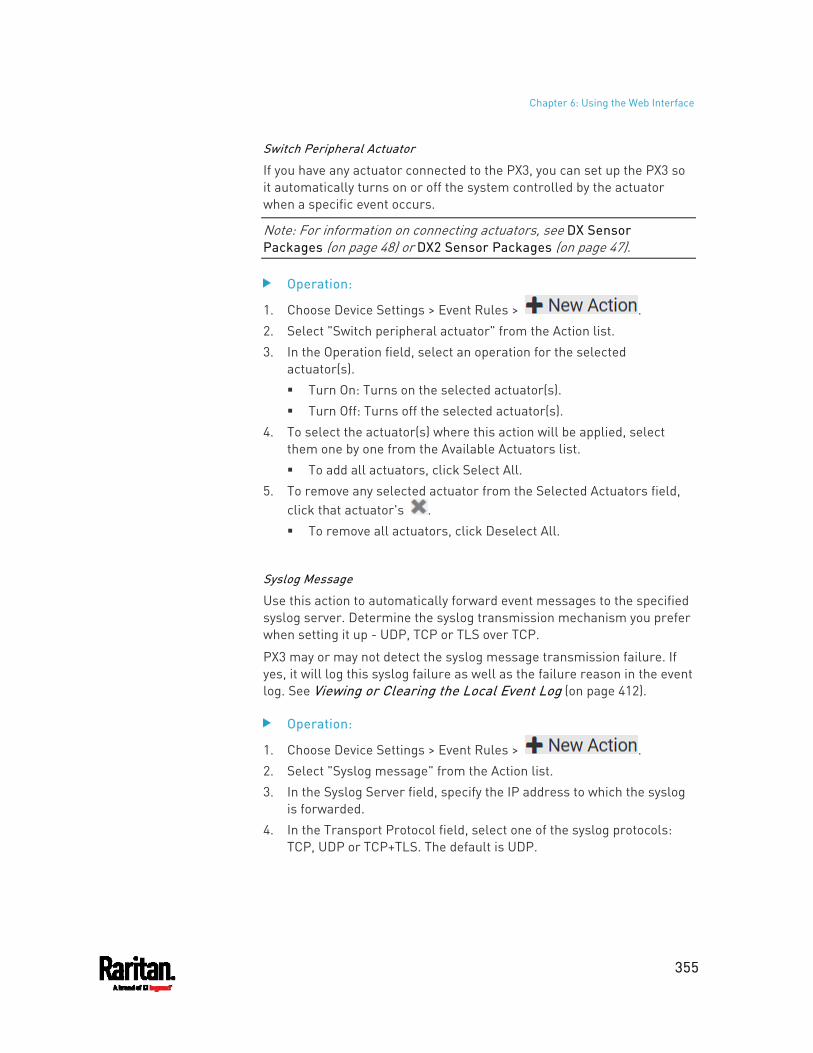
Chapter 6: Using the Web Interface
355
Switch Peripheral Actuator
If you have any actuator connected to the PX3, you can set up the PX3 so it automatically turns on or off the system controlled by the actuator when a specific event occurs.
Note: For information on connecting actuators, see DX Sensor Packages (on page 48) or DX2 Sensor Packages (on page 47).
Operation:
1. Choose Device Settings > Event Rules > . 2. Select "Switch peripheral actuator" from the Action list. 3. In the Operation field, select an operation for the selected
actuator(s). Turn On: Turns on the selected actuator(s). Turn Off: Turns off the selected actuator(s).
4. To select the actuator(s) where this action will be applied, select them one by one from the Available Actuators list. To add all actuators, click Select All.
5. To remove any selected actuator from the Selected Actuators field, click that actuator's . To remove all actuators, click Deselect All.
Syslog Message
Use this action to automatically forward event messages to the specified syslog server. Determine the syslog transmission mechanism you prefer when setting it up - UDP, TCP or TLS over TCP.
PX3 may or may not detect the syslog message transmission failure. If yes, it will log this syslog failure as well as the failure reason in the event log. See Viewing or Clearing the Local Event Log (on page 412).
Operation:
1. Choose Device Settings > Event Rules > . 2. Select "Syslog message" from the Action list. 3. In the Syslog Server field, specify the IP address to which the syslog
is forwarded. 4. In the Transport Protocol field, select one of the syslog protocols:
TCP, UDP or TCP+TLS. The default is UDP.
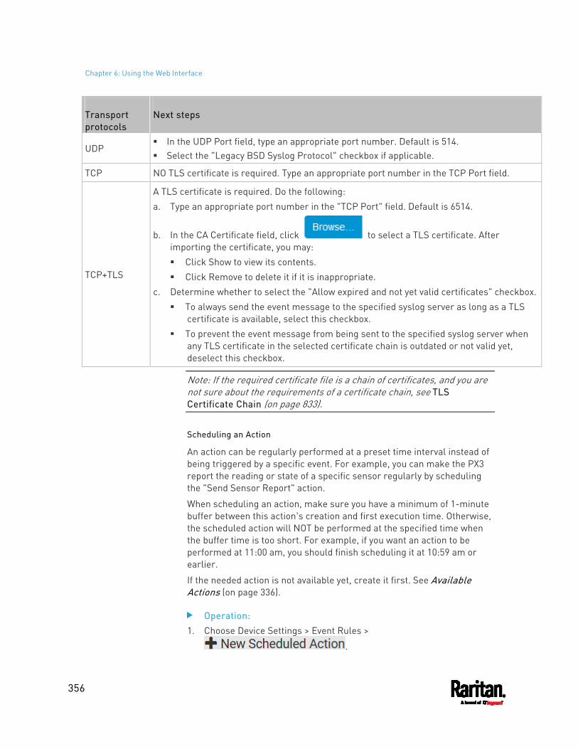
Chapter 6: Using the Web Interface
356
Transport protocols
Next steps
UDP In the UDP Port field, type an appropriate port number. Default is 514. Select the "Legacy BSD Syslog Protocol" checkbox if applicable.
TCP NO TLS certificate is required. Type an appropriate port number in the TCP Port field.
TCP+TLS
A TLS certificate is required. Do the following: a. Type an appropriate port number in the "TCP Port" field. Default is 6514.
b. In the CA Certificate field, click to select a TLS certificate. After importing the certificate, you may: Click Show to view its contents. Click Remove to delete it if it is inappropriate.
c. Determine whether to select the "Allow expired and not yet valid certificates" checkbox. To always send the event message to the specified syslog server as long as a TLS
certificate is available, select this checkbox. To prevent the event message from being sent to the specified syslog server when
any TLS certificate in the selected certificate chain is outdated or not valid yet, deselect this checkbox.
Note: If the required certificate file is a chain of certificates, and you are not sure about the requirements of a certificate chain, see TLS Certificate Chain (on page 833).
Scheduling an Action
An action can be regularly performed at a preset time interval instead of being triggered by a specific event. For example, you can make the PX3 report the reading or state of a specific sensor regularly by scheduling the "Send Sensor Report" action.
When scheduling an action, make sure you have a minimum of 1-minute buffer between this action's creation and first execution time. Otherwise, the scheduled action will NOT be performed at the specified time when the buffer time is too short. For example, if you want an action to be performed at 11:00 am, you should finish scheduling it at 10:59 am or earlier.
If the needed action is not available yet, create it first. See Available Actions (on page 336).
Operation: 1. Choose Device Settings > Event Rules >
.
Chapter 6: Using the Web Interface
357
2. To select any action(s), select them one by one from the Available Actions list. To select all available actions, click Select All.
3. To remove any action(s) from the Selected Actions field, click that action's . To remove all actions, click Deselect All.
4. Select the desired frequency in the Execution Time field, and then specify the time interval or a specific date and time in the field(s) that appear.
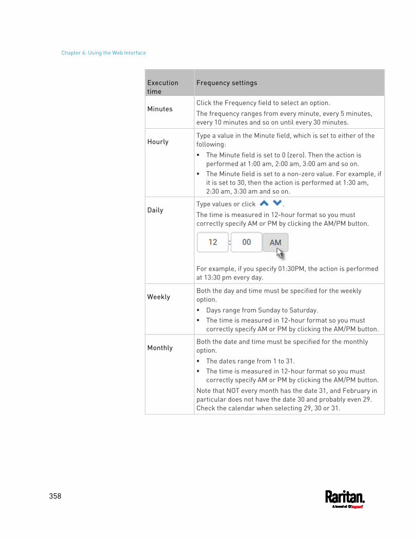
Chapter 6: Using the Web Interface
358
Execution time
Frequency settings
Minutes Click the Frequency field to select an option. The frequency ranges from every minute, every 5 minutes, every 10 minutes and so on until every 30 minutes.
Hourly Type a value in the Minute field, which is set to either of the following: The Minute field is set to 0 (zero). Then the action is
performed at 1:00 am, 2:00 am, 3:00 am and so on. The Minute field is set to a non-zero value. For example, if
it is set to 30, then the action is performed at 1:30 am, 2:30 am, 3:30 am and so on.
Daily Type values or click . The time is measured in 12-hour format so you must correctly specify AM or PM by clicking the AM/PM button.
For example, if you specify 01:30PM, the action is performed at 13:30 pm every day.
Weekly Both the day and time must be specified for the weekly option. Days range from Sunday to Saturday. The time is measured in 12-hour format so you must
correctly specify AM or PM by clicking the AM/PM button.
Monthly Both the date and time must be specified for the monthly option. The dates range from 1 to 31. The time is measured in 12-hour format so you must
correctly specify AM or PM by clicking the AM/PM button. Note that NOT every month has the date 31, and February in particular does not have the date 30 and probably even 29. Check the calendar when selecting 29, 30 or 31.
Chapter 6: Using the Web Interface
359
Execution time
Frequency settings
Yearly This option requires three settings: Month - January through December. Day of month - 1 to 31. Time - the value is measured in 12-hour format so you
must correctly specify AM or PM by clicking the AM/PM button.
An example of the scheduled action is available in the section titled Send Sensor Report Example (on page 359).
Send Sensor Report Example
To create a scheduled action for emailing a temperature sensor report hourly, it requires:
A 'Send email' action A 'Send sensor report' action A timer - that is, the scheduled action
Steps:
1. Click to create a 'Send email' action that sends an email to the desired recipient(s). For details, see Send Email (on page 345). In this example, this action is named Email a Sensor Report. If wanted, you can customize the email messages in this action.
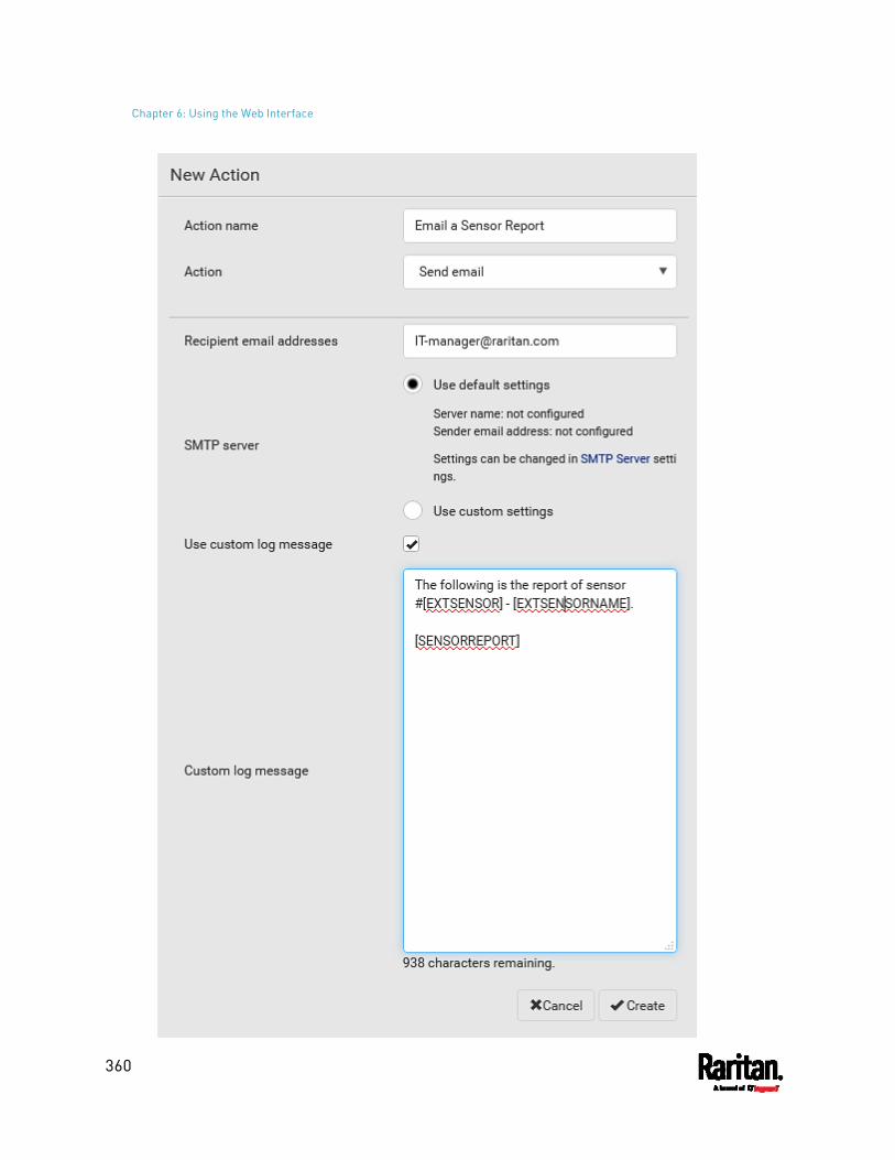
Chapter 6: Using the Web Interface
360
Chapter 6: Using the Web Interface
361
2. Click to create a 'Send sensor report' action that includes the 'Email a Sensor Report' action as its destination action. For details, see Send Sensor Report (on page 346). In this example, this action is named Send Temperature Sensor
Readings. You can specify more than one temperature sensor as needed in
this action.
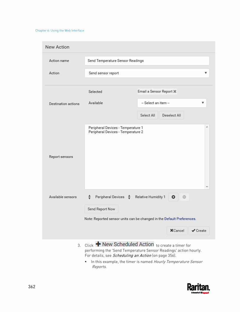
Chapter 6: Using the Web Interface
362
3. Click to create a timer for performing the 'Send Temperature Sensor Readings' action hourly. For details, see Scheduling an Action (on page 356). In this example, the timer is named Hourly Temperature Sensor
Reports.
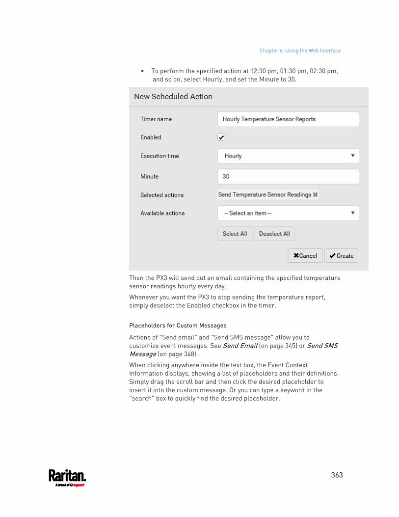
Chapter 6: Using the Web Interface
363
To perform the specified action at 12:30 pm, 01:30 pm, 02:30 pm, and so on, select Hourly, and set the Minute to 30.
Then the PX3 will send out an email containing the specified temperature sensor readings hourly every day.
Whenever you want the PX3 to stop sending the temperature report, simply deselect the Enabled checkbox in the timer.
Placeholders for Custom Messages
Actions of "Send email" and "Send SMS message" allow you to customize event messages. See Send Email (on page 345) or Send SMS Message (on page 348).
When clicking anywhere inside the text box, the Event Context Information displays, showing a list of placeholders and their definitions. Simply drag the scroll bar and then click the desired placeholder to insert it into the custom message. Or you can type a keyword in the "search" box to quickly find the desired placeholder.
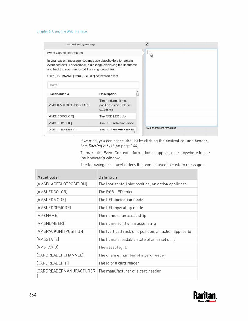
Chapter 6: Using the Web Interface
364
If wanted, you can resort the list by clicking the desired column header. See Sorting a List (on page 144).
To make the Event Context Information disappear, click anywhere inside the browser's window.
The following are placeholders that can be used in custom messages.
Placeholder Definition
[AMSBLADESLOTPOSITION] The (horizontal) slot position, an action applies to
[AMSLEDCOLOR] The RGB LED color
[AMSLEDMODE] The LED indication mode
[AMSLEDOPMODE] The LED operating mode
[AMSNAME] The name of an asset strip
[AMSNUMBER] The numeric ID of an asset strip
[AMSRACKUNITPOSITION] The (vertical) rack unit position, an action applies to
[AMSSTATE] The human readable state of an asset strip
[AMSTAGID] The asset tag ID
[CARDREADERCHANNEL] The channel number of a card reader
[CARDREADERID] The id of a card reader
[CARDREADERMANUFACTURER]
The manufacturer of a card reader
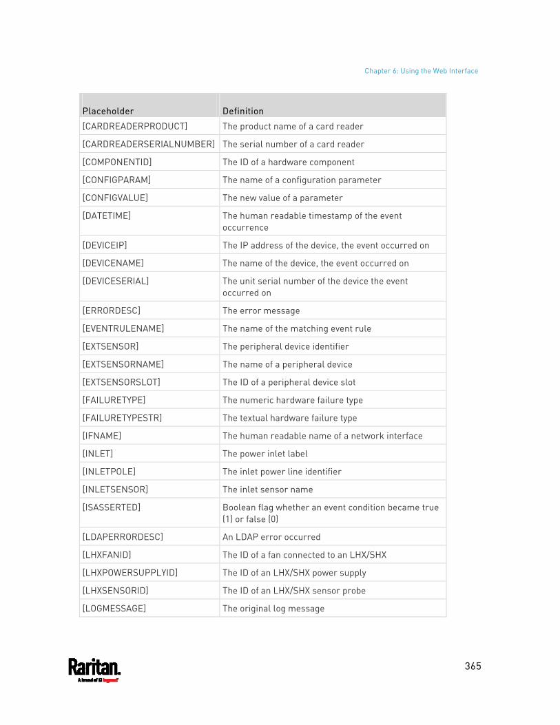
Chapter 6: Using the Web Interface
365
Placeholder Definition
[CARDREADERPRODUCT] The product name of a card reader
[CARDREADERSERIALNUMBER] The serial number of a card reader
[COMPONENTID] The ID of a hardware component
[CONFIGPARAM] The name of a configuration parameter
[CONFIGVALUE] The new value of a parameter
[DATETIME] The human readable timestamp of the event occurrence
[DEVICEIP] The IP address of the device, the event occurred on
[DEVICENAME] The name of the device, the event occurred on
[DEVICESERIAL] The unit serial number of the device the event occurred on
[ERRORDESC] The error message
[EVENTRULENAME] The name of the matching event rule
[EXTSENSOR] The peripheral device identifier
[EXTSENSORNAME] The name of a peripheral device
[EXTSENSORSLOT] The ID of a peripheral device slot
[FAILURETYPE] The numeric hardware failure type
[FAILURETYPESTR] The textual hardware failure type
[IFNAME] The human readable name of a network interface
[INLET] The power inlet label
[INLETPOLE] The inlet power line identifier
[INLETSENSOR] The inlet sensor name
[ISASSERTED] Boolean flag whether an event condition became true (1) or false (0)
[LDAPERRORDESC] An LDAP error occurred
[LHXFANID] The ID of a fan connected to an LHX/SHX
[LHXPOWERSUPPLYID] The ID of an LHX/SHX power supply
[LHXSENSORID] The ID of an LHX/SHX sensor probe
[LOGMESSAGE] The original log message
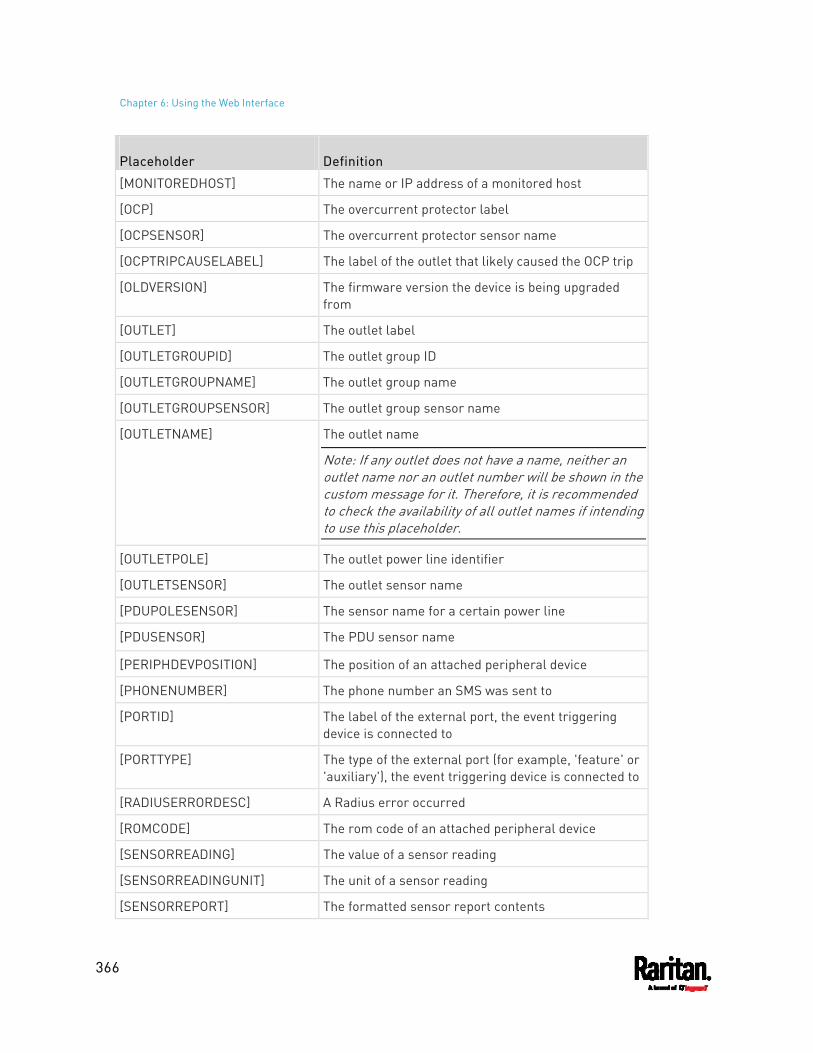
Chapter 6: Using the Web Interface
366
Placeholder Definition
[MONITOREDHOST] The name or IP address of a monitored host
[OCP] The overcurrent protector label
[OCPSENSOR] The overcurrent protector sensor name
[OCPTRIPCAUSELABEL] The label of the outlet that likely caused the OCP trip
[OLDVERSION] The firmware version the device is being upgraded from
[OUTLET] The outlet label
[OUTLETGROUPID] The outlet group ID
[OUTLETGROUPNAME] The outlet group name
[OUTLETGROUPSENSOR] The outlet group sensor name
[OUTLETNAME] The outlet name
Note: If any outlet does not have a name, neither an outlet name nor an outlet number will be shown in the custom message for it. Therefore, it is recommended to check the availability of all outlet names if intending to use this placeholder.
[OUTLETPOLE] The outlet power line identifier
[OUTLETSENSOR] The outlet sensor name
[PDUPOLESENSOR] The sensor name for a certain power line
[PDUSENSOR] The PDU sensor name
[PERIPHDEVPOSITION] The position of an attached peripheral device
[PHONENUMBER] The phone number an SMS was sent to
[PORTID] The label of the external port, the event triggering device is connected to
[PORTTYPE] The type of the external port (for example, 'feature' or 'auxiliary'), the event triggering device is connected to
[RADIUSERRORDESC] A Radius error occurred
[ROMCODE] The rom code of an attached peripheral device
[SENSORREADING] The value of a sensor reading
[SENSORREADINGUNIT] The unit of a sensor reading
[SENSORREPORT] The formatted sensor report contents
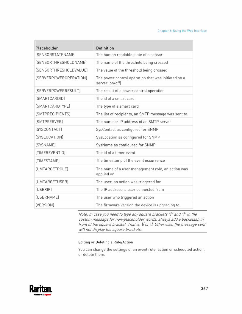
Chapter 6: Using the Web Interface
367
Placeholder Definition
[SENSORSTATENAME] The human readable state of a sensor
[SENSORTHRESHOLDNAME] The name of the threshold being crossed
[SENSORTHRESHOLDVALUE] The value of the threshold being crossed
[SERVERPOWEROPERATION] The power control operation that was initiated on a server (on/off)
[SERVERPOWERRESULT] The result of a power control operation
[SMARTCARDID] The id of a smart card
[SMARTCARDTYPE] The type of a smart card
[SMTPRECIPIENTS] The list of recipients, an SMTP message was sent to
[SMTPSERVER] The name or IP address of an SMTP server
[SYSCONTACT] SysContact as configured for SNMP
[SYSLOCATION] SysLocation as configured for SNMP
[SYSNAME] SysName as configured for SNMP
[TIMEREVENTID] The id of a timer event
[TIMESTAMP] The timestamp of the event occurrence
[UMTARGETROLE] The name of a user management role, an action was applied on
[UMTARGETUSER] The user, an action was triggered for
[USERIP] The IP address, a user connected from
[USERNAME] The user who triggered an action
[VERSION] The firmware version the device is upgrading to
Note: In case you need to type any square brackets "[" and "]" in the custom message for non-placeholder words, always add a backslash in front of the square bracket. That is, \[ or \]. Otherwise, the message sent will not display the square brackets.
Editing or Deleting a Rule/Action
You can change the settings of an event rule, action or scheduled action, or delete them.
Chapter 6: Using the Web Interface
368
Exception: Some settings of the built-in event rules or actions are not user-configurable. Besides, you cannot delete built-in rules and actions. See Built-in Rules and Rule Configuration (on page 315) or Available Actions (on page 336).
To edit or delete an event rule, action or scheduled action: 1. Choose Device Settings > Event Rules. 2. Click the desired one in the list of rules, actions or scheduled actions.
Its setup page opens. 3. Perform the desired action.
To modify settings, make necessary changes and then click Save.
To delete it, click on the top-right corner. Then click Delete on the confirmation message.
Sample Event Rules
Sample PDU-Level Event Rule
In this example, we want the PX3 to record the firmware upgrade failure in the internal log when it happens.
The event rule involves:
Event: Device > Firmware update failed Action: System Event Log Action
To create this PDU-level event rule: 1. For an event at the PDU level, select "Device" in the Event field. 2. Select "Firmware update failed" so that the PX3 responds to the
event related to firmware upgrade failure. 3. To make the PX3 record the firmware update failure event in the
internal log, select "System Event Log Action" in the 'Available actions' field.
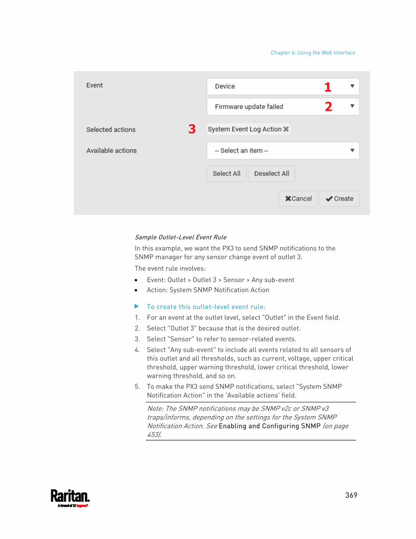
Chapter 6: Using the Web Interface
369
Sample Outlet-Level Event Rule
In this example, we want the PX3 to send SNMP notifications to the SNMP manager for any sensor change event of outlet 3.
The event rule involves:
Event: Outlet > Outlet 3 > Sensor > Any sub-event Action: System SNMP Notification Action
To create this outlet-level event rule: 1. For an event at the outlet level, select "Outlet" in the Event field. 2. Select "Outlet 3" because that is the desired outlet. 3. Select "Sensor" to refer to sensor-related events. 4. Select "Any sub-event" to include all events related to all sensors of
this outlet and all thresholds, such as current, voltage, upper critical threshold, upper warning threshold, lower critical threshold, lower warning threshold, and so on.
5. To make the PX3 send SNMP notifications, select "System SNMP Notification Action" in the 'Available actions' field.
Note: The SNMP notifications may be SNMP v2c or SNMP v3 traps/informs, depending on the settings for the System SNMP Notification Action. See Enabling and Configuring SNMP (on page 453).
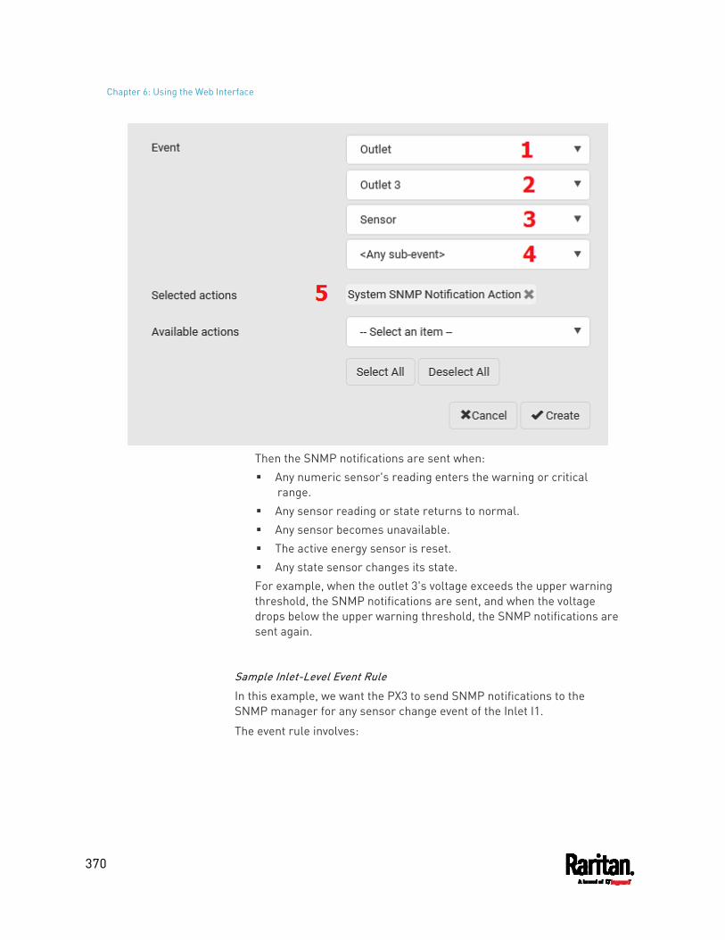
Chapter 6: Using the Web Interface
370
Then the SNMP notifications are sent when: Any numeric sensor's reading enters the warning or critical
range. Any sensor reading or state returns to normal. Any sensor becomes unavailable. The active energy sensor is reset. Any state sensor changes its state. For example, when the outlet 3's voltage exceeds the upper warning threshold, the SNMP notifications are sent, and when the voltage drops below the upper warning threshold, the SNMP notifications are sent again.
Sample Inlet-Level Event Rule
In this example, we want the PX3 to send SNMP notifications to the SNMP manager for any sensor change event of the Inlet I1.
The event rule involves:
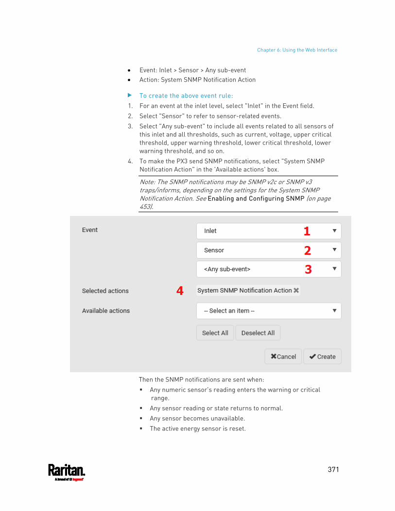
Chapter 6: Using the Web Interface
371
Event: Inlet > Sensor > Any sub-event Action: System SNMP Notification Action
To create the above event rule: 1. For an event at the inlet level, select "Inlet" in the Event field. 2. Select "Sensor" to refer to sensor-related events. 3. Select "Any sub-event" to include all events related to all sensors of
this inlet and all thresholds, such as current, voltage, upper critical threshold, upper warning threshold, lower critical threshold, lower warning threshold, and so on.
4. To make the PX3 send SNMP notifications, select "System SNMP Notification Action" in the 'Available actions' box.
Note: The SNMP notifications may be SNMP v2c or SNMP v3 traps/informs, depending on the settings for the System SNMP Notification Action. See Enabling and Configuring SNMP (on page 453).
Then the SNMP notifications are sent when: Any numeric sensor's reading enters the warning or critical
range. Any sensor reading or state returns to normal. Any sensor becomes unavailable. The active energy sensor is reset.
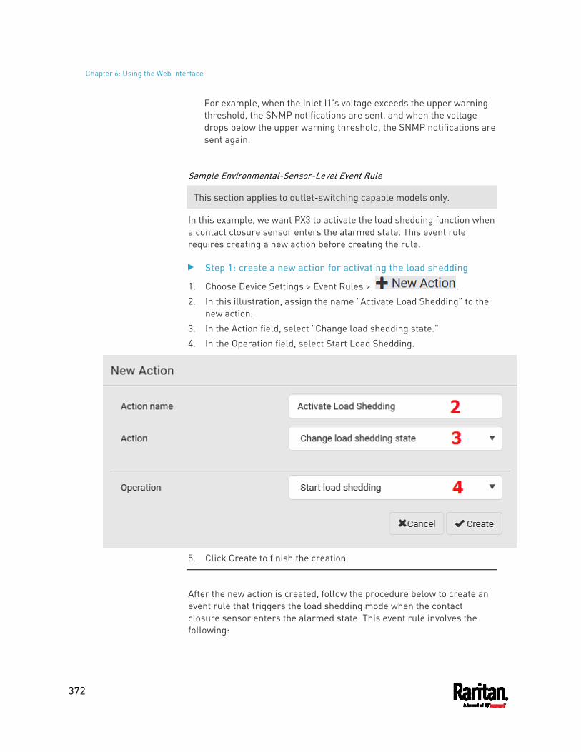
Chapter 6: Using the Web Interface
372
For example, when the Inlet I1's voltage exceeds the upper warning threshold, the SNMP notifications are sent, and when the voltage drops below the upper warning threshold, the SNMP notifications are sent again.
Sample Environmental-Sensor-Level Event Rule
This section applies to outlet-switching capable models only.
In this example, we want PX3 to activate the load shedding function when a contact closure sensor enters the alarmed state. This event rule requires creating a new action before creating the rule.
Step 1: create a new action for activating the load shedding
1. Choose Device Settings > Event Rules > . 2. In this illustration, assign the name "Activate Load Shedding" to the
new action. 3. In the Action field, select "Change load shedding state." 4. In the Operation field, select Start Load Shedding.
5. Click Create to finish the creation.
After the new action is created, follow the procedure below to create an event rule that triggers the load shedding mode when the contact closure sensor enters the alarmed state. This event rule involves the following:
Chapter 6: Using the Web Interface
373
Event: Peripheral Device Slot > Slot 1 > State Sensor/Actuator > Alarmed/Open/On
Trigger condition: Alarmed Action: Activate Load Shedding
Step 2: create the contact closure-triggered load shedding event rule
1. Click on the Event Rules page. 2. In this illustration, assign the name "Contact Closure Triggered Load
Shedding" to the new rule. 3. In the Event field, select "Peripheral Device Slot" to indicate we are
specifying an event related to the environmental sensor package. 4. Select the ID number of the desired contact closure sensor. In this
illustration, the ID number of the desired contact closure sensor is 1, so select Slot 1.
Note: ID numbers of all sensors/actuators are available on the Peripherals page. See Peripherals (on page 207).
5. Select "State Sensor/Actuator" because the contact closure sensor is a state sensor.
6. Select "Alarmed" since we want the PX3 to respond when the selected contact closure sensor changes its state related to the "alarmed" state.
7. In the "Trigger condition" field, select the Alarmed/Open/On radio button so that the action is taken only when the contact closure sensor enters the alarmed state.
8. Select "Activate Load Shedding" from the 'Available actions' list.
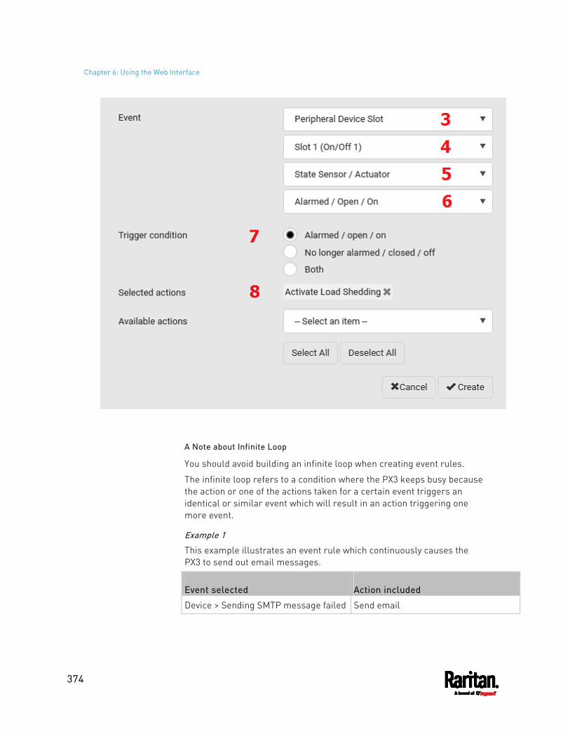
Chapter 6: Using the Web Interface
374
A Note about Infinite Loop
You should avoid building an infinite loop when creating event rules.
The infinite loop refers to a condition where the PX3 keeps busy because the action or one of the actions taken for a certain event triggers an identical or similar event which will result in an action triggering one more event.
Example 1
This example illustrates an event rule which continuously causes the PX3 to send out email messages.
Event selected Action included
Device > Sending SMTP message failed Send email
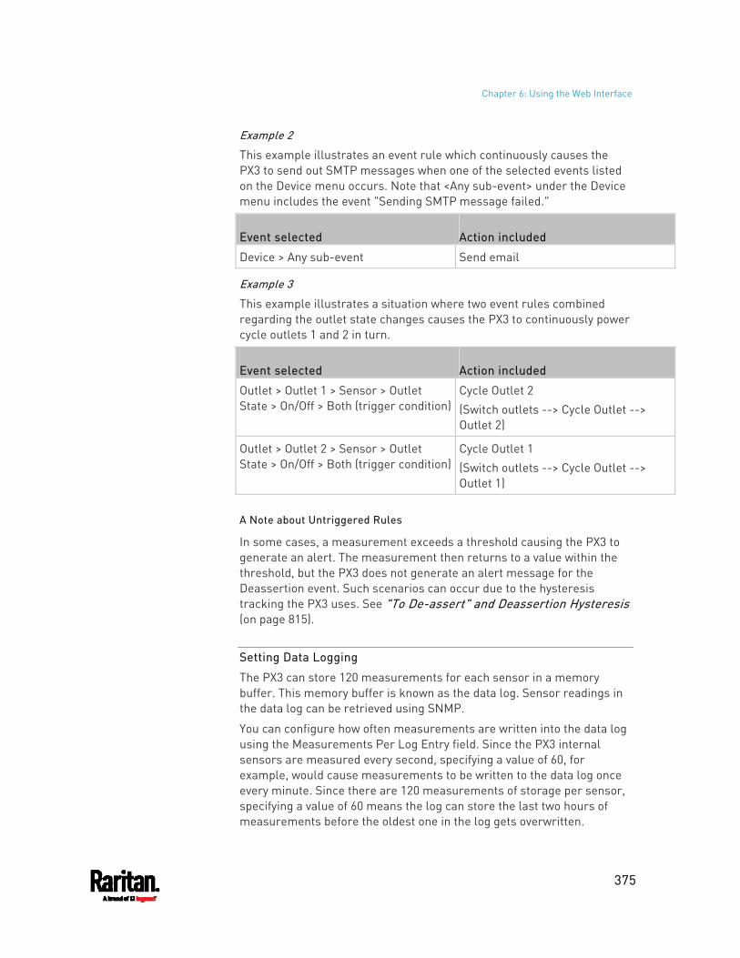
Chapter 6: Using the Web Interface
375
Example 2
This example illustrates an event rule which continuously causes the PX3 to send out SMTP messages when one of the selected events listed on the Device menu occurs. Note that <Any sub-event> under the Device menu includes the event "Sending SMTP message failed."
Event selected Action included
Device > Any sub-event Send email
Example 3
This example illustrates a situation where two event rules combined regarding the outlet state changes causes the PX3 to continuously power cycle outlets 1 and 2 in turn.
Event selected Action included
Outlet > Outlet 1 > Sensor > Outlet State > On/Off > Both (trigger condition)
Cycle Outlet 2 (Switch outlets --> Cycle Outlet --> Outlet 2)
Outlet > Outlet 2 > Sensor > Outlet State > On/Off > Both (trigger condition)
Cycle Outlet 1 (Switch outlets --> Cycle Outlet --> Outlet 1)
A Note about Untriggered Rules
In some cases, a measurement exceeds a threshold causing the PX3 to generate an alert. The measurement then returns to a value within the threshold, but the PX3 does not generate an alert message for the Deassertion event. Such scenarios can occur due to the hysteresis tracking the PX3 uses. See "To De-assert" and Deassertion Hysteresis (on page 815).
Setting Data Logging
The PX3 can store 120 measurements for each sensor in a memory buffer. This memory buffer is known as the data log. Sensor readings in the data log can be retrieved using SNMP.
You can configure how often measurements are written into the data log using the Measurements Per Log Entry field. Since the PX3 internal sensors are measured every second, specifying a value of 60, for example, would cause measurements to be written to the data log once every minute. Since there are 120 measurements of storage per sensor, specifying a value of 60 means the log can store the last two hours of measurements before the oldest one in the log gets overwritten.
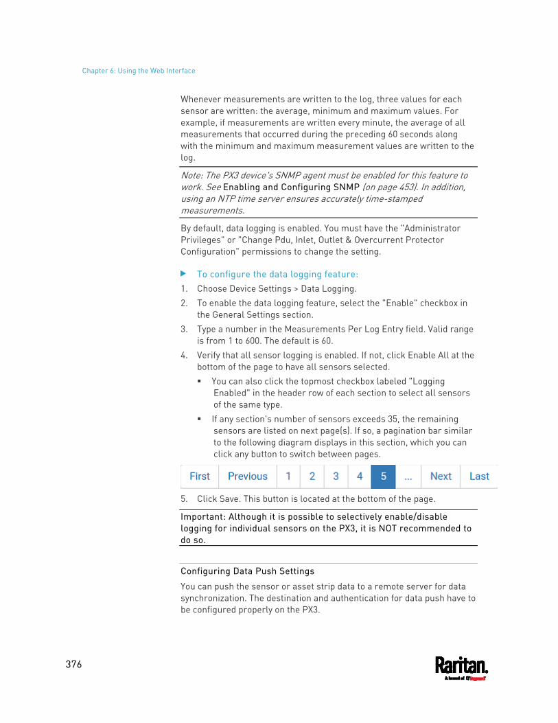
Chapter 6: Using the Web Interface
376
Whenever measurements are written to the log, three values for each sensor are written: the average, minimum and maximum values. For example, if measurements are written every minute, the average of all measurements that occurred during the preceding 60 seconds along with the minimum and maximum measurement values are written to the log.
Note: The PX3 device's SNMP agent must be enabled for this feature to work. See Enabling and Configuring SNMP (on page 453). In addition, using an NTP time server ensures accurately time-stamped measurements.
By default, data logging is enabled. You must have the "Administrator Privileges" or "Change Pdu, Inlet, Outlet & Overcurrent Protector Configuration" permissions to change the setting.
To configure the data logging feature: 1. Choose Device Settings > Data Logging. 2. To enable the data logging feature, select the "Enable" checkbox in
the General Settings section. 3. Type a number in the Measurements Per Log Entry field. Valid range
is from 1 to 600. The default is 60. 4. Verify that all sensor logging is enabled. If not, click Enable All at the
bottom of the page to have all sensors selected. You can also click the topmost checkbox labeled "Logging
Enabled" in the header row of each section to select all sensors of the same type.
If any section's number of sensors exceeds 35, the remaining sensors are listed on next page(s). If so, a pagination bar similar to the following diagram displays in this section, which you can click any button to switch between pages.
5. Click Save. This button is located at the bottom of the page.
Important: Although it is possible to selectively enable/disable logging for individual sensors on the PX3, it is NOT recommended to do so.
Configuring Data Push Settings
You can push the sensor or asset strip data to a remote server for data synchronization. The destination and authentication for data push have to be configured properly on the PX3.
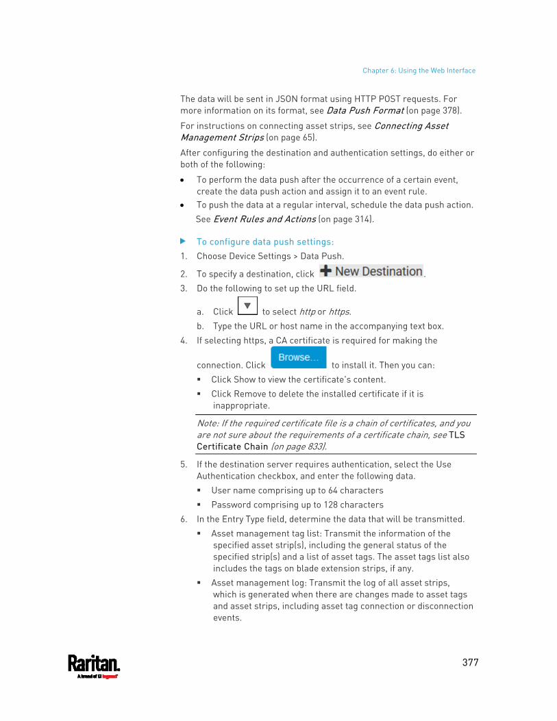
Chapter 6: Using the Web Interface
377
The data will be sent in JSON format using HTTP POST requests. For more information on its format, see Data Push Format (on page 378).
For instructions on connecting asset strips, see Connecting Asset Management Strips (on page 65).
After configuring the destination and authentication settings, do either or both of the following:
To perform the data push after the occurrence of a certain event, create the data push action and assign it to an event rule.
To push the data at a regular interval, schedule the data push action. See Event Rules and Actions (on page 314).
To configure data push settings: 1. Choose Device Settings > Data Push.
2. To specify a destination, click . 3. Do the following to set up the URL field.
a. Click to select http or https. b. Type the URL or host name in the accompanying text box.
4. If selecting https, a CA certificate is required for making the
connection. Click to install it. Then you can: Click Show to view the certificate's content. Click Remove to delete the installed certificate if it is
inappropriate.
Note: If the required certificate file is a chain of certificates, and you are not sure about the requirements of a certificate chain, see TLS Certificate Chain (on page 833).
5. If the destination server requires authentication, select the Use Authentication checkbox, and enter the following data. User name comprising up to 64 characters Password comprising up to 128 characters
6. In the Entry Type field, determine the data that will be transmitted. Asset management tag list: Transmit the information of the
specified asset strip(s), including the general status of the specified strip(s) and a list of asset tags. The asset tags list also includes the tags on blade extension strips, if any.
Asset management log: Transmit the log of all asset strips, which is generated when there are changes made to asset tags and asset strips, including asset tag connection or disconnection events.
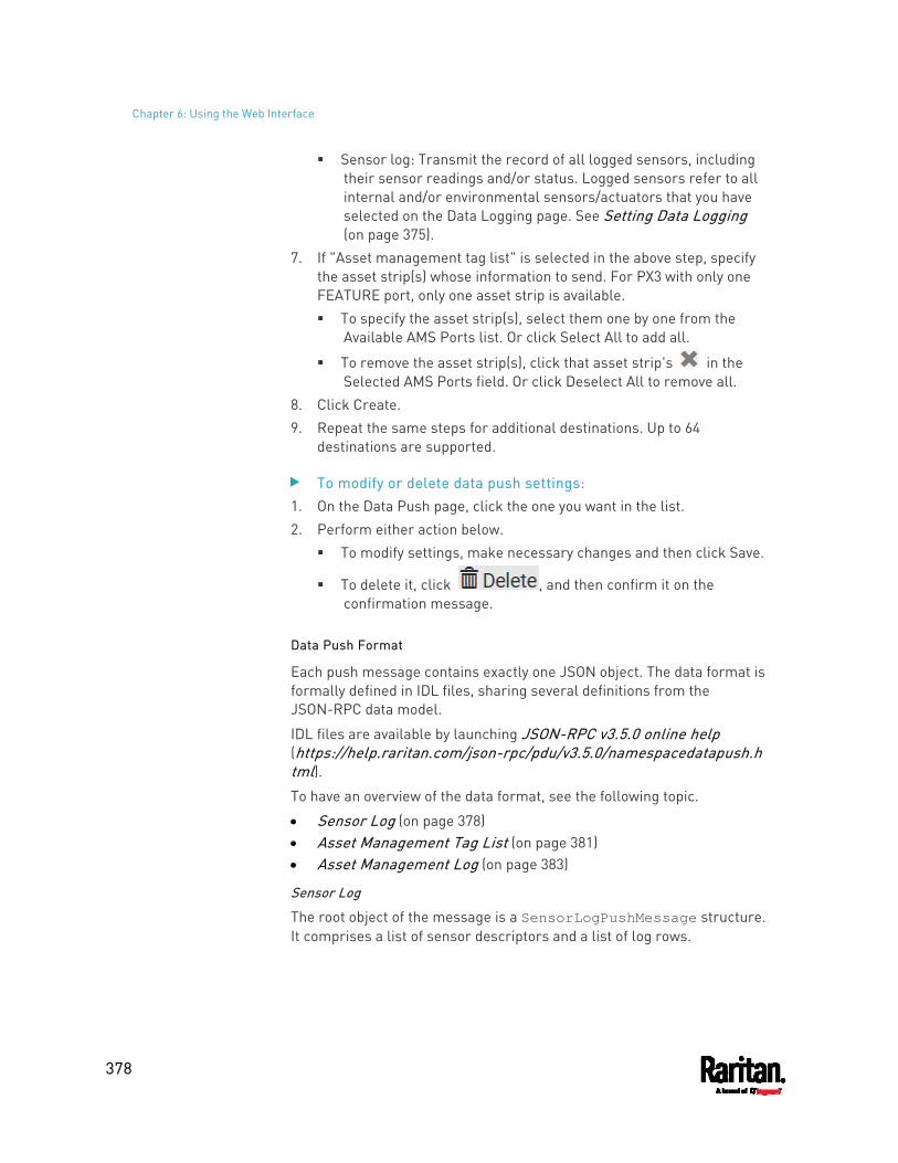
Chapter 6: Using the Web Interface
378
Sensor log: Transmit the record of all logged sensors, including their sensor readings and/or status. Logged sensors refer to all internal and/or environmental sensors/actuators that you have selected on the Data Logging page. See Setting Data Logging (on page 375).
7. If "Asset management tag list" is selected in the above step, specify the asset strip(s) whose information to send. For PX3 with only one FEATURE port, only one asset strip is available. To specify the asset strip(s), select them one by one from the
Available AMS Ports list. Or click Select All to add all.
To remove the asset strip(s), click that asset strip's in the Selected AMS Ports field. Or click Deselect All to remove all.
8. Click Create. 9. Repeat the same steps for additional destinations. Up to 64
destinations are supported.
To modify or delete data push settings: 1. On the Data Push page, click the one you want in the list. 2. Perform either action below.
To modify settings, make necessary changes and then click Save.
To delete it, click , and then confirm it on the confirmation message.
Data Push Format
Each push message contains exactly one JSON object. The data format is formally defined in IDL files, sharing several definitions from the JSON-RPC data model.
IDL files are available by launching JSON-RPC v3.5.0 online help (https://help.raritan.com/json-rpc/pdu/v3.5.0/namespacedatapush.html). To have an overview of the data format, see the following topic.
Sensor Log (on page 378) Asset Management Tag List (on page 381) Asset Management Log (on page 383)
Sensor Log
The root object of the message is a SensorLogPushMessage structure. It comprises a list of sensor descriptors and a list of log rows.
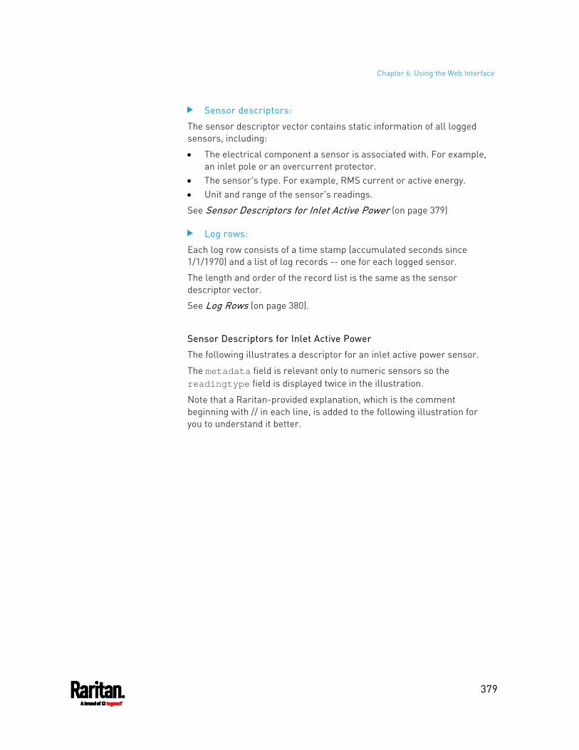
Chapter 6: Using the Web Interface
379
Sensor descriptors:
The sensor descriptor vector contains static information of all logged sensors, including:
The electrical component a sensor is associated with. For example, an inlet pole or an overcurrent protector.
The sensor's type. For example, RMS current or active energy. Unit and range of the sensor's readings.
See Sensor Descriptors for Inlet Active Power (on page 379)
Log rows:
Each log row consists of a time stamp (accumulated seconds since 1/1/1970) and a list of log records -- one for each logged sensor.
The length and order of the record list is the same as the sensor descriptor vector.
See Log Rows (on page 380).
Sensor Descriptors for Inlet Active Power
The following illustrates a descriptor for an inlet active power sensor.
The metadata field is relevant only to numeric sensors so the readingtype field is displayed twice in the illustration.
Note that a Raritan-provided explanation, which is the comment beginning with // in each line, is added to the following illustration for you to understand it better.
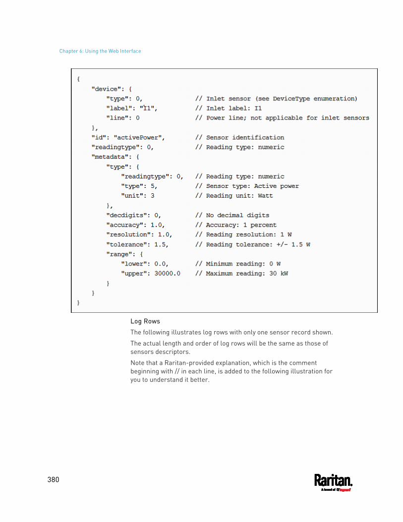
Chapter 6: Using the Web Interface
380
Log Rows
The following illustrates log rows with only one sensor record shown.
The actual length and order of log rows will be the same as those of sensors descriptors.
Note that a Raritan-provided explanation, which is the comment beginning with // in each line, is added to the following illustration for you to understand it better.
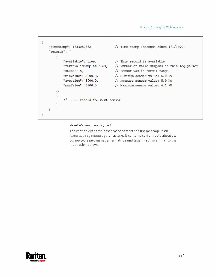
Chapter 6: Using the Web Interface
381
Asset Management Tag List
The root object of the asset management tag list message is an AssetStripsMessage structure. It contains current data about all connected asset management strips and tags, which is similar to the illustration below.
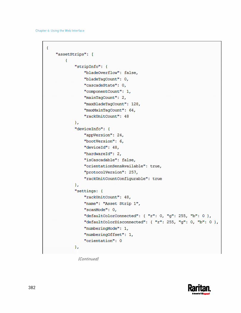
Chapter 6: Using the Web Interface
382
(Continued)
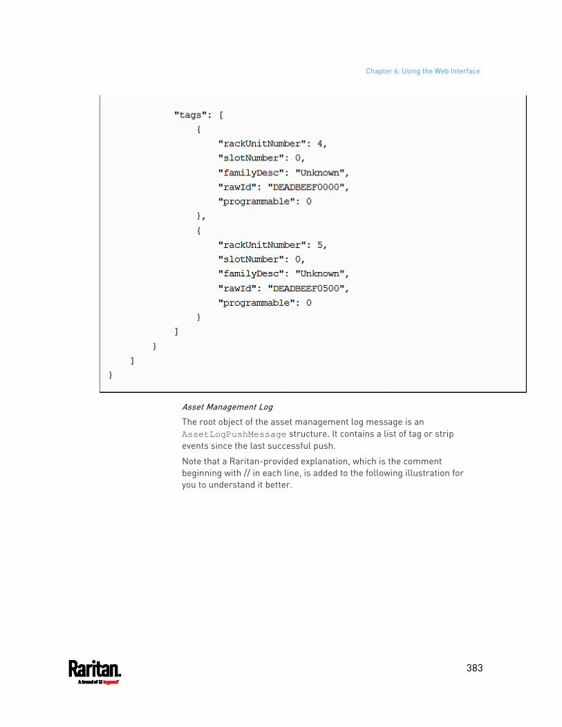
Chapter 6: Using the Web Interface
383
Asset Management Log
The root object of the asset management log message is an AssetLogPushMessage structure. It contains a list of tag or strip events since the last successful push.
Note that a Raritan-provided explanation, which is the comment beginning with // in each line, is added to the following illustration for you to understand it better.
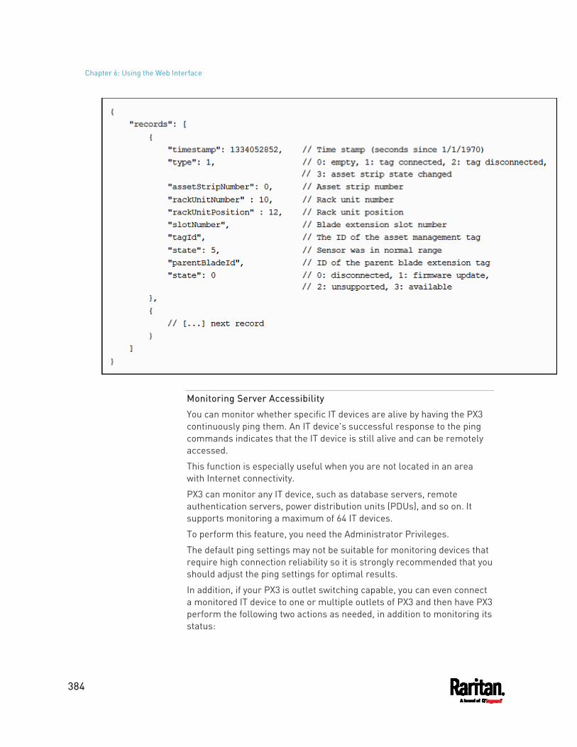
Chapter 6: Using the Web Interface
384
Monitoring Server Accessibility
You can monitor whether specific IT devices are alive by having the PX3 continuously ping them. An IT device's successful response to the ping commands indicates that the IT device is still alive and can be remotely accessed.
This function is especially useful when you are not located in an area with Internet connectivity.
PX3 can monitor any IT device, such as database servers, remote authentication servers, power distribution units (PDUs), and so on. It supports monitoring a maximum of 64 IT devices.
To perform this feature, you need the Administrator Privileges.
The default ping settings may not be suitable for monitoring devices that require high connection reliability so it is strongly recommended that you should adjust the ping settings for optimal results.
In addition, if your PX3 is outlet switching capable, you can even connect a monitored IT device to one or multiple outlets of PX3 and then have PX3 perform the following two actions as needed, in addition to monitoring its status:
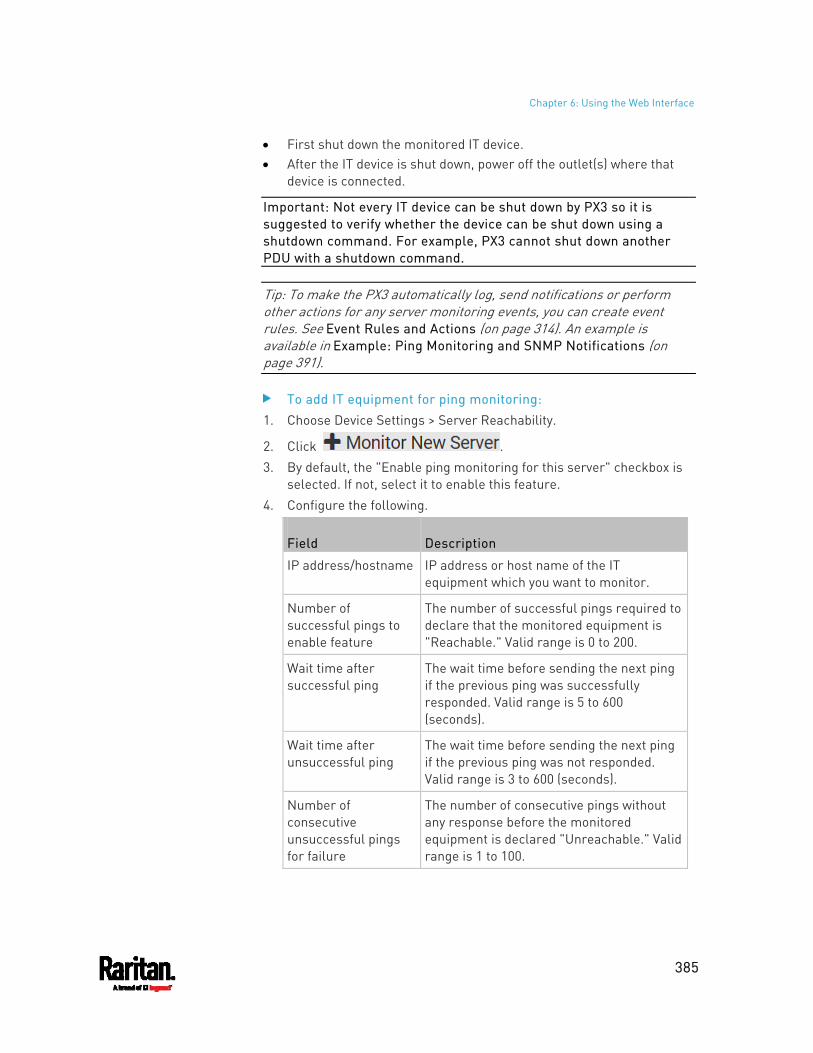
Chapter 6: Using the Web Interface
385
First shut down the monitored IT device. After the IT device is shut down, power off the outlet(s) where that
device is connected.
Important: Not every IT device can be shut down by PX3 so it is suggested to verify whether the device can be shut down using a shutdown command. For example, PX3 cannot shut down another PDU with a shutdown command.
Tip: To make the PX3 automatically log, send notifications or perform other actions for any server monitoring events, you can create event rules. See Event Rules and Actions (on page 314). An example is available in Example: Ping Monitoring and SNMP Notifications (on page 391).
To add IT equipment for ping monitoring: 1. Choose Device Settings > Server Reachability.
2. Click . 3. By default, the "Enable ping monitoring for this server" checkbox is
selected. If not, select it to enable this feature. 4. Configure the following.
Field Description
IP address/hostname IP address or host name of the IT equipment which you want to monitor.
Number of successful pings to enable feature
The number of successful pings required to declare that the monitored equipment is "Reachable." Valid range is 0 to 200.
Wait time after successful ping
The wait time before sending the next ping if the previous ping was successfully responded. Valid range is 5 to 600 (seconds).
Wait time after unsuccessful ping
The wait time before sending the next ping if the previous ping was not responded. Valid range is 3 to 600 (seconds).
Number of consecutive unsuccessful pings for failure
The number of consecutive pings without any response before the monitored equipment is declared "Unreachable." Valid range is 1 to 100.
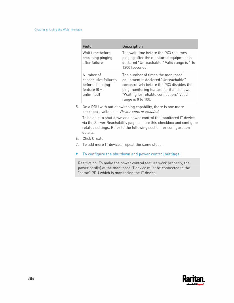
Chapter 6: Using the Web Interface
386
Field Description
Wait time before resuming pinging after failure
The wait time before the PX3 resumes pinging after the monitored equipment is declared "Unreachable." Valid range is 1 to 1200 (seconds).
Number of consecutive failures before disabling feature (0 = unlimited)
The number of times the monitored equipment is declared "Unreachable" consecutively before the PX3 disables the ping monitoring feature for it and shows "Waiting for reliable connection." Valid range is 0 to 100.
5. On a PDU with outlet switching capability, there is one more checkbox available -- Power control enabled. To be able to shut down and power control the monitored IT device via the Server Reachability page, enable this checkbox and configure related settings. Refer to the following section for configuration details.
6. Click Create. 7. To add more IT devices, repeat the same steps.
To configure the shutdown and power control settings:
Restriction: To make the power control feature work properly, the power cord(s) of the monitored IT device must be connected to the "same" PDU which is monitoring the IT device.
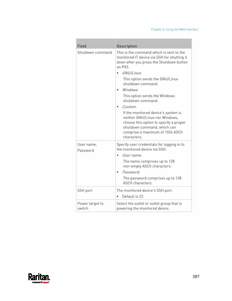
Chapter 6: Using the Web Interface
387
Field Description
Shutdown command This is the command which is sent to the monitored IT device via SSH for shutting it down after you press the Shutdown button on PX3. GNU/Linux:
This option sends the GNU/Linux shutdown command.
Windows: This option sends the Windows shutdown command.
Custom: If the monitored device's system is neither GNU/Linux nor Windows, choose this option to specify a proper shutdown command, which can comprise a maximum of 1024 ASCII characters.
User name, Password
Specify user credentials for logging in to the monitored device via SSH. User name:
The name comprises up to 128 non-empty ASCII characters.
Password: The password comprises up to 128 ASCII characters.
SSH port The monitored device's SSH port. Default is 22.
Power target to switch
Select the outlet or outlet group that is powering the monitored device.
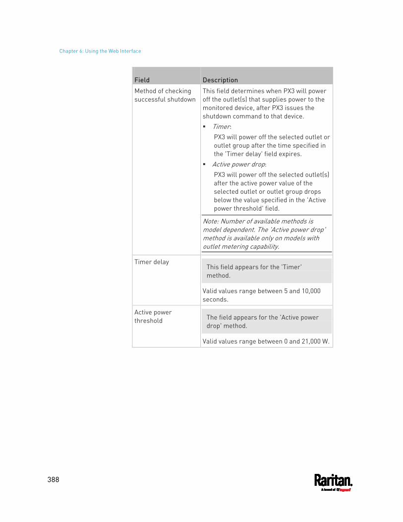
Chapter 6: Using the Web Interface
388
Field Description
Method of checking successful shutdown
This field determines when PX3 will power off the outlet(s) that supplies power to the monitored device, after PX3 issues the shutdown command to that device. Timer:
PX3 will power off the selected outlet or outlet group after the time specified in the 'Timer delay' field expires.
Active power drop: PX3 will power off the selected outlet(s) after the active power value of the selected outlet or outlet group drops below the value specified in the 'Active power threshold' field.
Note: Number of available methods is model dependent. The 'Active power drop' method is available only on models with outlet metering capability.
Timer delay This field appears for the 'Timer' method.
Valid values range between 5 and 10,000 seconds.
Active power threshold The field appears for the 'Active power
drop' method.
Valid values range between 0 and 21,000 W.
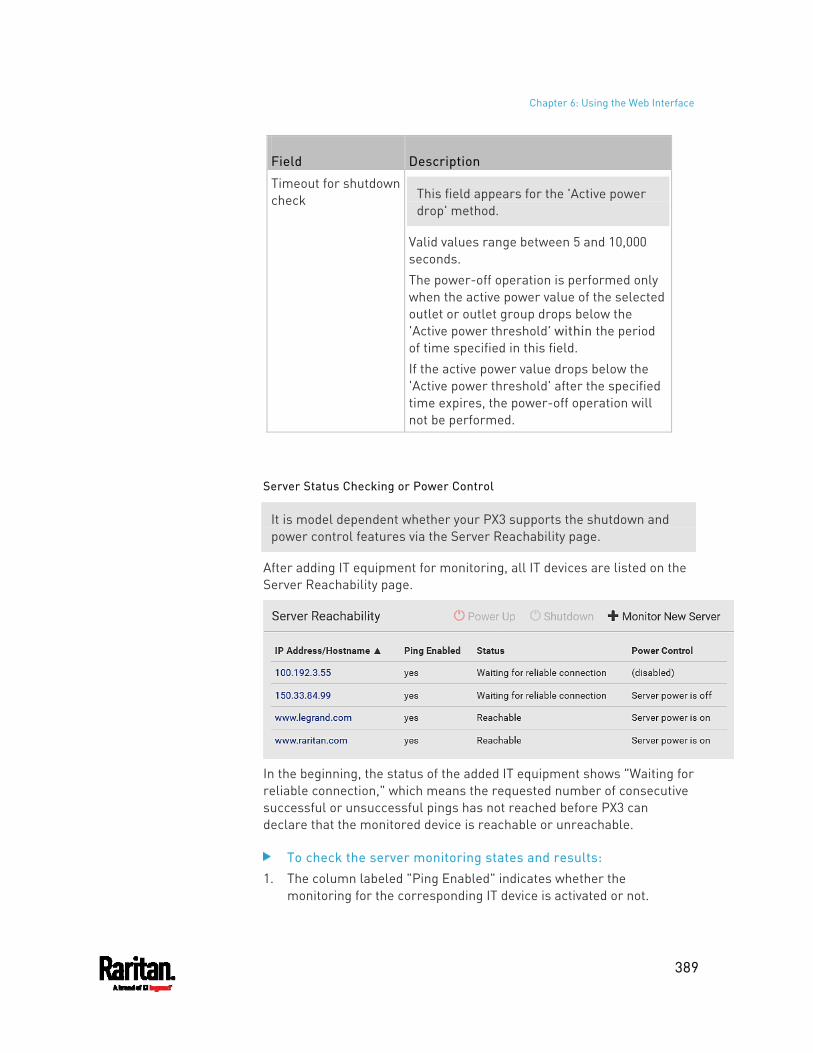
Chapter 6: Using the Web Interface
389
Field Description
Timeout for shutdown check This field appears for the 'Active power
drop' method.
Valid values range between 5 and 10,000 seconds. The power-off operation is performed only when the active power value of the selected outlet or outlet group drops below the 'Active power threshold' within the period of time specified in this field. If the active power value drops below the 'Active power threshold' after the specified time expires, the power-off operation will not be performed.
Server Status Checking or Power Control
It is model dependent whether your PX3 supports the shutdown and power control features via the Server Reachability page.
After adding IT equipment for monitoring, all IT devices are listed on the Server Reachability page.
In the beginning, the status of the added IT equipment shows "Waiting for reliable connection," which means the requested number of consecutive successful or unsuccessful pings has not reached before PX3 can declare that the monitored device is reachable or unreachable.
To check the server monitoring states and results: 1. The column labeled "Ping Enabled" indicates whether the
monitoring for the corresponding IT device is activated or not.
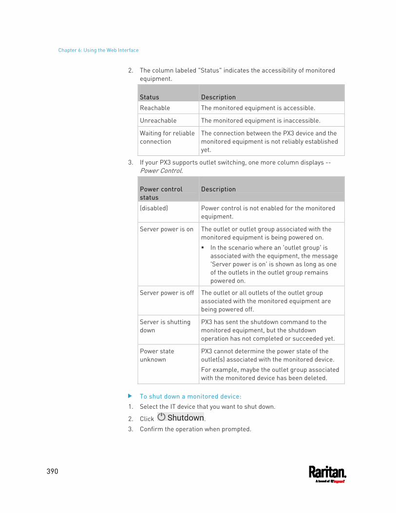
Chapter 6: Using the Web Interface
390
2. The column labeled "Status" indicates the accessibility of monitored equipment.
Status Description
Reachable The monitored equipment is accessible.
Unreachable The monitored equipment is inaccessible.
Waiting for reliable connection
The connection between the PX3 device and the monitored equipment is not reliably established yet.
3. If your PX3 supports outlet switching, one more column displays -- Power Control.
Power control status
Description
(disabled) Power control is not enabled for the monitored equipment.
Server power is on The outlet or outlet group associated with the monitored equipment is being powered on. In the scenario where an 'outlet group' is
associated with the equipment, the message 'Server power is on' is shown as long as one of the outlets in the outlet group remains powered on.
Server power is off The outlet or all outlets of the outlet group associated with the monitored equipment are being powered off.
Server is shutting down
PX3 has sent the shutdown command to the monitored equipment, but the shutdown operation has not completed or succeeded yet.
Power state unknown
PX3 cannot determine the power state of the outlet(s) associated with the monitored device. For example, maybe the outlet group associated with the monitored device has been deleted.
To shut down a monitored device: 1. Select the IT device that you want to shut down.
2. Click . 3. Confirm the operation when prompted.
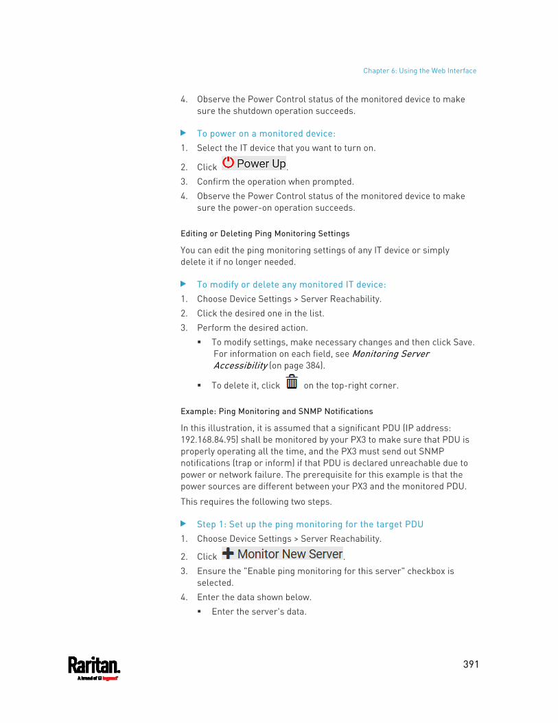
Chapter 6: Using the Web Interface
391
4. Observe the Power Control status of the monitored device to make sure the shutdown operation succeeds.
To power on a monitored device: 1. Select the IT device that you want to turn on.
2. Click . 3. Confirm the operation when prompted. 4. Observe the Power Control status of the monitored device to make
sure the power-on operation succeeds.
Editing or Deleting Ping Monitoring Settings
You can edit the ping monitoring settings of any IT device or simply delete it if no longer needed.
To modify or delete any monitored IT device: 1. Choose Device Settings > Server Reachability. 2. Click the desired one in the list. 3. Perform the desired action.
To modify settings, make necessary changes and then click Save. For information on each field, see Monitoring Server Accessibility (on page 384).
To delete it, click on the top-right corner.
Example: Ping Monitoring and SNMP Notifications
In this illustration, it is assumed that a significant PDU (IP address: 192.168.84.95) shall be monitored by your PX3 to make sure that PDU is properly operating all the time, and the PX3 must send out SNMP notifications (trap or inform) if that PDU is declared unreachable due to power or network failure. The prerequisite for this example is that the power sources are different between your PX3 and the monitored PDU.
This requires the following two steps.
Step 1: Set up the ping monitoring for the target PDU 1. Choose Device Settings > Server Reachability.
2. Click . 3. Ensure the "Enable ping monitoring for this server" checkbox is
selected. 4. Enter the data shown below.
Enter the server's data.
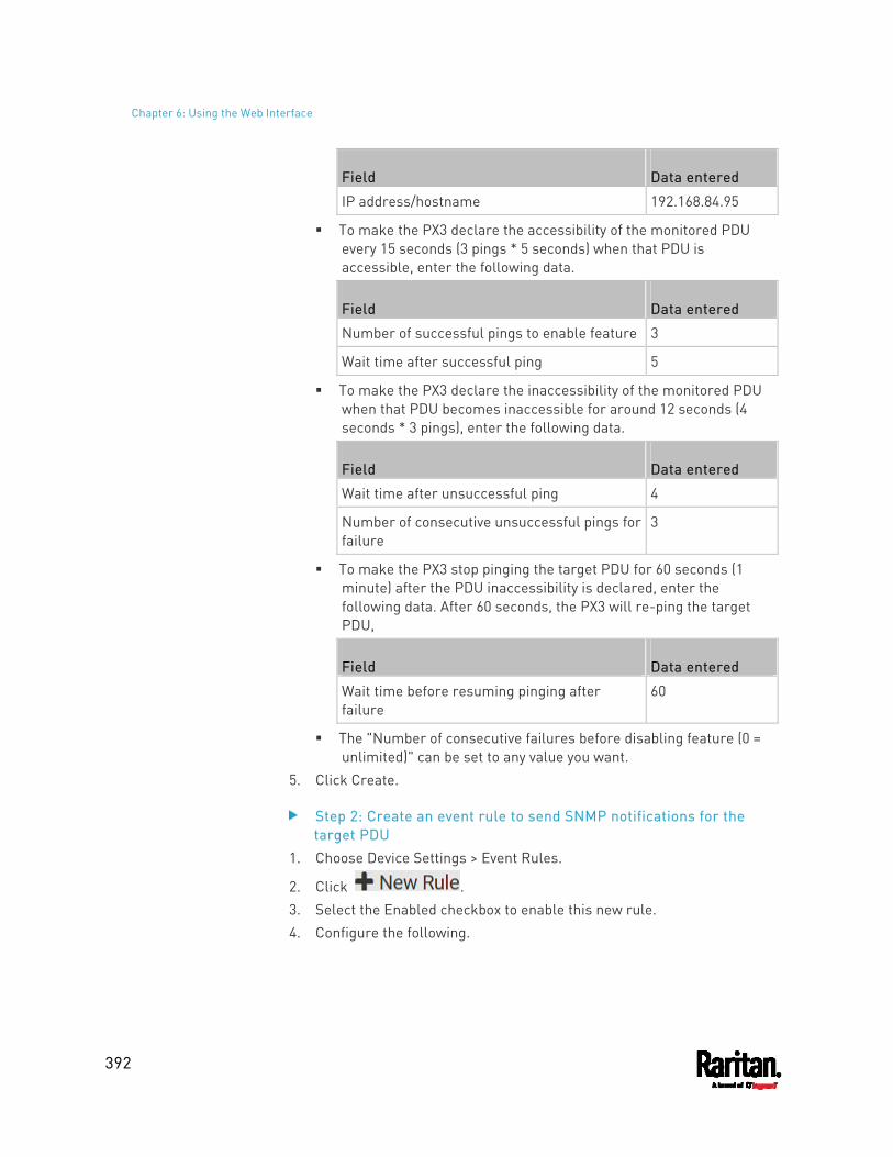
Chapter 6: Using the Web Interface
392
Field Data entered
IP address/hostname 192.168.84.95
To make the PX3 declare the accessibility of the monitored PDU every 15 seconds (3 pings * 5 seconds) when that PDU is accessible, enter the following data.
Field Data entered
Number of successful pings to enable feature 3
Wait time after successful ping 5
To make the PX3 declare the inaccessibility of the monitored PDU when that PDU becomes inaccessible for around 12 seconds (4 seconds * 3 pings), enter the following data.
Field Data entered
Wait time after unsuccessful ping 4
Number of consecutive unsuccessful pings for failure
3
To make the PX3 stop pinging the target PDU for 60 seconds (1 minute) after the PDU inaccessibility is declared, enter the following data. After 60 seconds, the PX3 will re-ping the target PDU,
Field Data entered
Wait time before resuming pinging after failure
60
The "Number of consecutive failures before disabling feature (0 = unlimited)" can be set to any value you want.
5. Click Create.
Step 2: Create an event rule to send SNMP notifications for the target PDU
1. Choose Device Settings > Event Rules.
2. Click . 3. Select the Enabled checkbox to enable this new rule. 4. Configure the following.
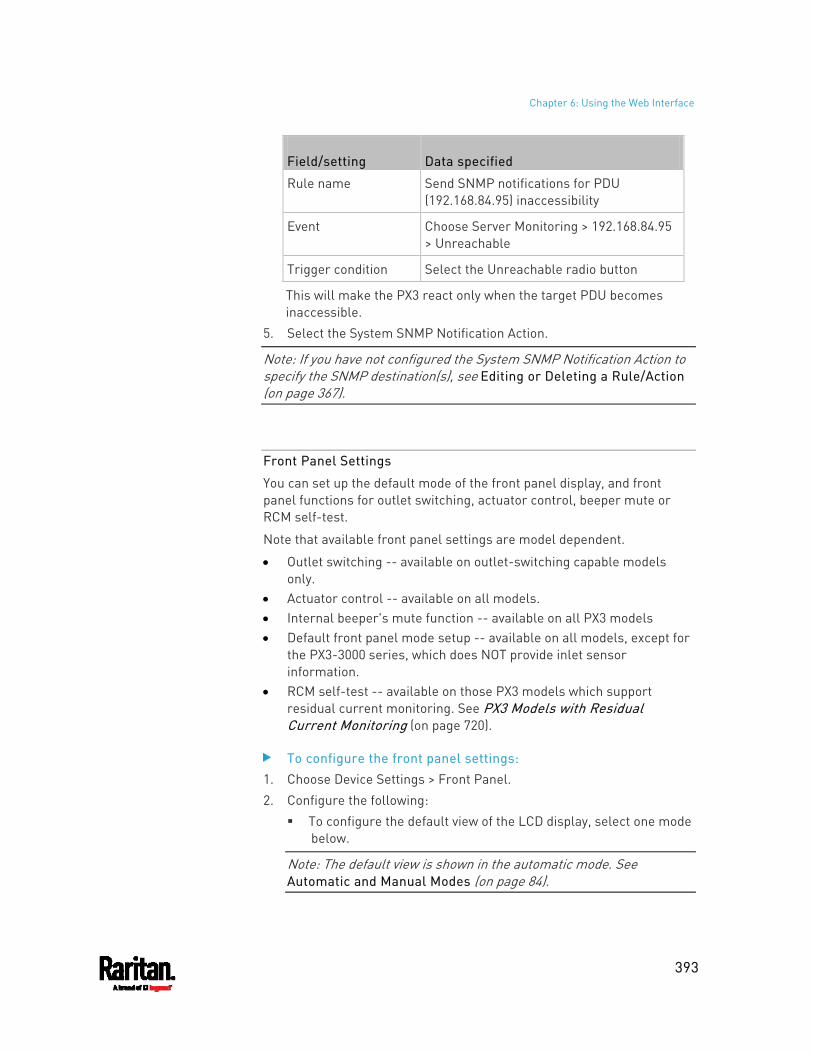
Chapter 6: Using the Web Interface
393
Field/setting Data specified
Rule name Send SNMP notifications for PDU (192.168.84.95) inaccessibility
Event Choose Server Monitoring > 192.168.84.95 > Unreachable
Trigger condition Select the Unreachable radio button
This will make the PX3 react only when the target PDU becomes inaccessible.
5. Select the System SNMP Notification Action.
Note: If you have not configured the System SNMP Notification Action to specify the SNMP destination(s), see Editing or Deleting a Rule/Action (on page 367).
Front Panel Settings
You can set up the default mode of the front panel display, and front panel functions for outlet switching, actuator control, beeper mute or RCM self-test.
Note that available front panel settings are model dependent.
Outlet switching -- available on outlet-switching capable models only.
Actuator control -- available on all models. Internal beeper's mute function -- available on all PX3 models Default front panel mode setup -- available on all models, except for
the PX3-3000 series, which does NOT provide inlet sensor information.
RCM self-test -- available on those PX3 models which support residual current monitoring. See PX3 Models with Residual Current Monitoring (on page 720).
To configure the front panel settings: 1. Choose Device Settings > Front Panel. 2. Configure the following:
To configure the default view of the LCD display, select one mode below.
Note: The default view is shown in the automatic mode. See Automatic and Manual Modes (on page 84).
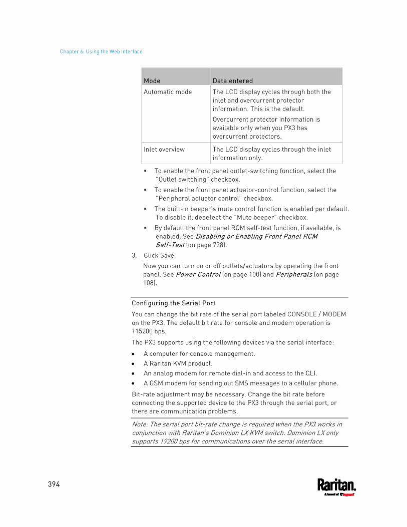
Chapter 6: Using the Web Interface
394
Mode Data entered
Automatic mode The LCD display cycles through both the inlet and overcurrent protector information. This is the default. Overcurrent protector information is available only when you PX3 has overcurrent protectors.
Inlet overview The LCD display cycles through the inlet information only.
To enable the front panel outlet-switching function, select the "Outlet switching" checkbox.
To enable the front panel actuator-control function, select the "Peripheral actuator control" checkbox.
The built-in beeper's mute control function is enabled per default. To disable it, deselect the "Mute beeper" checkbox.
By default the front panel RCM self-test function, if available, is enabled. See Disabling or Enabling Front Panel RCM Self-Test (on page 728).
3. Click Save. Now you can turn on or off outlets/actuators by operating the front panel. See Power Control (on page 100) and Peripherals (on page 108).
Configuring the Serial Port
You can change the bit rate of the serial port labeled CONSOLE / MODEM on the PX3. The default bit rate for console and modem operation is 115200 bps.
The PX3 supports using the following devices via the serial interface:
A computer for console management. A Raritan KVM product. An analog modem for remote dial-in and access to the CLI. A GSM modem for sending out SMS messages to a cellular phone.
Bit-rate adjustment may be necessary. Change the bit rate before connecting the supported device to the PX3 through the serial port, or there are communication problems.
Note: The serial port bit-rate change is required when the PX3 works in conjunction with Raritan's Dominion LX KVM switch. Dominion LX only supports 19200 bps for communications over the serial interface.
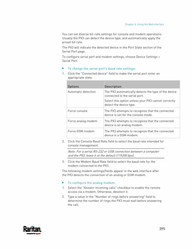
Chapter 6: Using the Web Interface
395
You can set diverse bit-rate settings for console and modem operations. Usually the PX3 can detect the device type, and automatically apply the preset bit rate.
The PX3 will indicate the detected device in the Port State section of the Serial Port page.
To configure serial port and modem settings, choose Device Settings > Serial Port.
To change the serial port's baud rate settings: 1. Click the "Connected device" field to make the serial port enter an
appropriate state.
Options Description
Automatic detection The PX3 automatically detects the type of the device connected to the serial port. Select this option unless your PX3 cannot correctly detect the device type.
Force console The PX3 attempts to recognize that the connected device is set for the console mode.
Force analog modem The PX3 attempts to recognize that the connected device is an analog modem.
Force GSM modem The PX3 attempts to recognize that the connected device is a GSM modem.
2. Click the Console Baud Rate field to select the baud rate intended for console management.
Note: For a serial RS-232 or USB connection between a computer and the PX3, leave it at the default (115200 bps).
3. Click the Modem Baud Rate field to select the baud rate for the modem connected to the PX3.
The following modem settings/fields appear in the web interface after the PX3 detects the connection of an analog or GSM modem.
To configure the analog modem: 1. Select the "Answer incoming calls" checkbox to enable the remote
access via a modem. Otherwise, deselect it. 2. Type a value in the "Number of rings before answering" field to
determine the number of rings the PX3 must wait before answering the call.
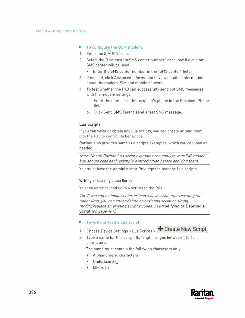
Chapter 6: Using the Web Interface
396
To configure the GSM modem: 1. Enter the SIM PIN code. 2. Select the "Use custom SMS center number" checkbox if a custom
SMS center will be used. Enter the SMS center number in the "SMS center" field.
3. If needed, click Advanced Information to view detailed information about the modem, SIM and mobile network.
4. To test whether the PX3 can successfully send out SMS messages with the modem settings: a. Enter the number of the recipient's phone in the Recipient Phone
field. b. Click Send SMS Test to send a test SMS message.
Lua Scripts
If you can write or obtain any Lua scripts, you can create or load them into the PX3 to control its behaviors.
Raritan also provides some Lua scripts examples, which you can load as needed.
Note: Not all Raritan Lua script examples can apply to your PX3 model. You should read each example's introduction before applying them.
You must have the Administrator Privileges to manage Lua scripts.
Writing or Loading a Lua Script
You can enter or load up to 4 scripts to the PX3.
Tip: If you can no longer enter or load a new script after reaching the upper limit, you can either delete any existing script or simply modify/replace an existing script's codes. See Modifying or Deleting a Script (on page 401).
To write or load a Lua script:
1. Choose Device Settings > Lua Scripts > . 2. Type a name for this script. Its length ranges between 1 to 63
characters. The name must contain the following characters only. Alphanumeric characters Underscore (_) Minus (-)
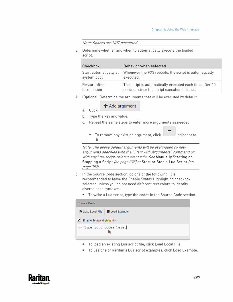
Chapter 6: Using the Web Interface
397
Note: Spaces are NOT permitted.
3. Determine whether and when to automatically execute the loaded script.
Checkbox Behavior when selected
Start automatically at system boot
Whenever the PX3 reboots, the script is automatically executed.
Restart after termination
The script is automatically executed each time after 10 seconds since the script execution finishes.
4. (Optional) Determine the arguments that will be executed by default.
a. Click . b. Type the key and value. c. Repeat the same steps to enter more arguments as needed.
To remove any existing argument, click adjacent to it.
Note: The above default arguments will be overridden by new arguments specified with the "Start with Arguments" command or with any Lua-script-related event rule. See Manually Starting or Stopping a Script (on page 398) or Start or Stop a Lua Script (on page 352).
5. In the Source Code section, do one of the following. It is recommended to leave the Enable Syntax Highlighting checkbox selected unless you do not need different text colors to identify diverse code syntaxes. To write a Lua script, type the codes in the Source Code section.
To load an existing Lua script file, click Load Local File. To use one of Raritan's Lua script examples, click Load Example.
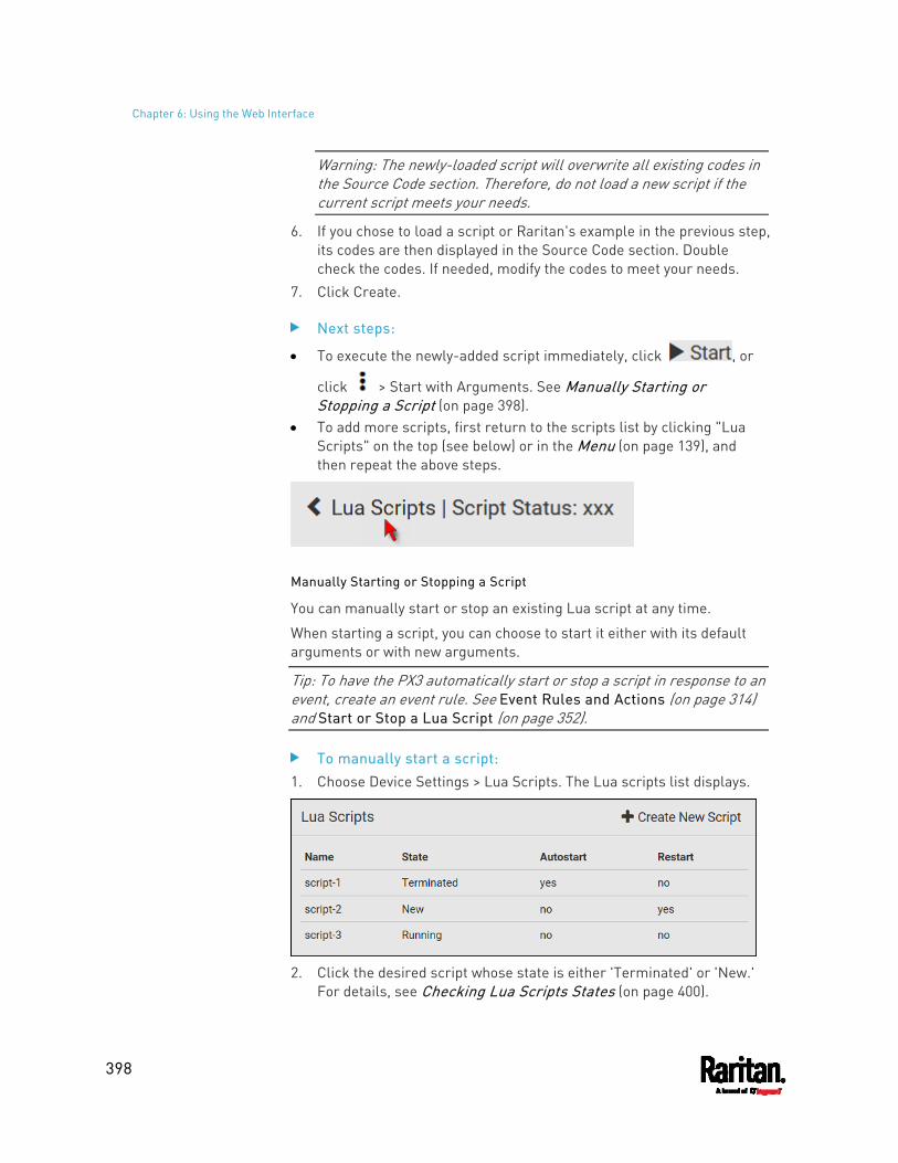
Chapter 6: Using the Web Interface
398
Warning: The newly-loaded script will overwrite all existing codes in the Source Code section. Therefore, do not load a new script if the current script meets your needs.
6. If you chose to load a script or Raritan's example in the previous step, its codes are then displayed in the Source Code section. Double check the codes. If needed, modify the codes to meet your needs.
7. Click Create.
Next steps:
To execute the newly-added script immediately, click , or
click > Start with Arguments. See Manually Starting or Stopping a Script (on page 398).
To add more scripts, first return to the scripts list by clicking "Lua Scripts" on the top (see below) or in the Menu (on page 139), and then repeat the above steps.
Manually Starting or Stopping a Script
You can manually start or stop an existing Lua script at any time.
When starting a script, you can choose to start it either with its default arguments or with new arguments.
Tip: To have the PX3 automatically start or stop a script in response to an event, create an event rule. See Event Rules and Actions (on page 314) and Start or Stop a Lua Script (on page 352).
To manually start a script: 1. Choose Device Settings > Lua Scripts. The Lua scripts list displays.
2. Click the desired script whose state is either 'Terminated' or 'New.'
For details, see Checking Lua Scripts States (on page 400).
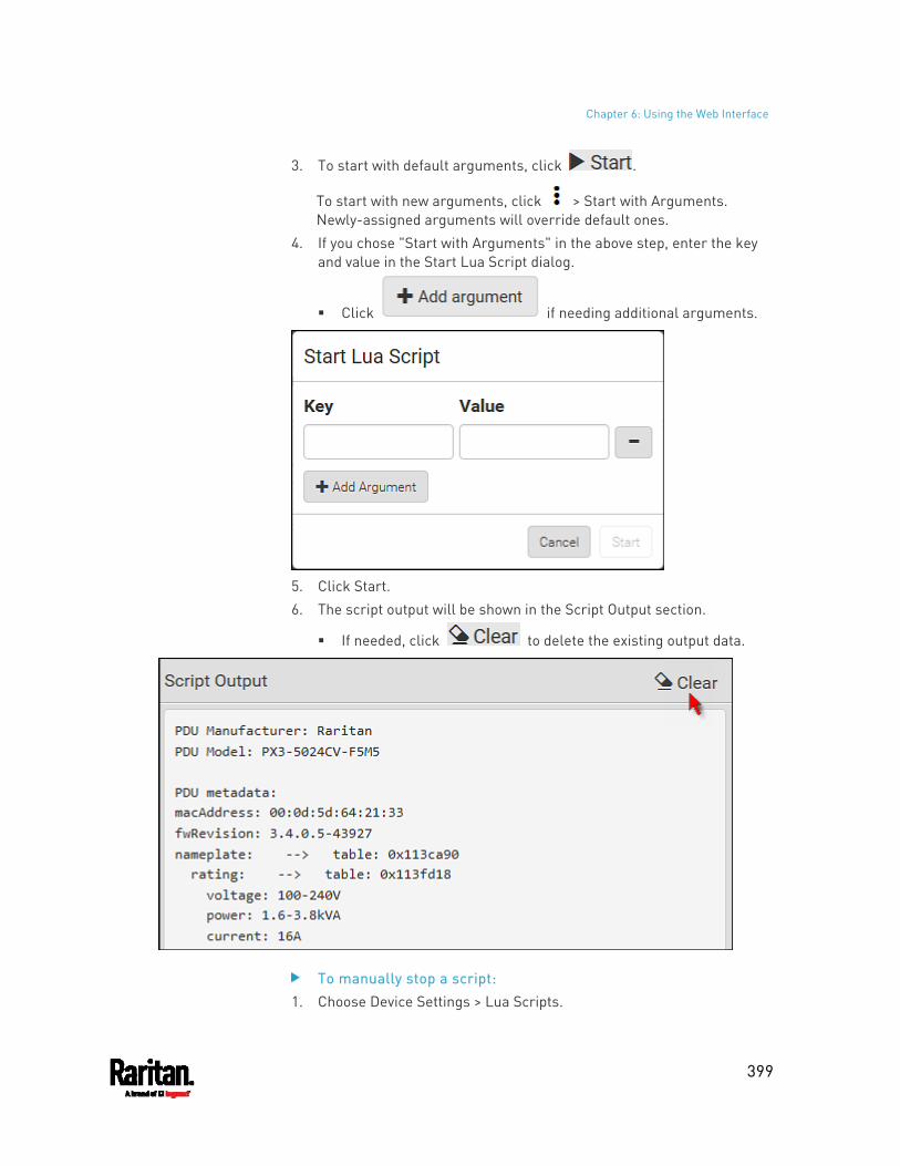
Chapter 6: Using the Web Interface
399
3. To start with default arguments, click .
To start with new arguments, click > Start with Arguments. Newly-assigned arguments will override default ones.
4. If you chose "Start with Arguments" in the above step, enter the key and value in the Start Lua Script dialog.
Click if needing additional arguments.
5. Click Start. 6. The script output will be shown in the Script Output section.
If needed, click to delete the existing output data.
To manually stop a script: 1. Choose Device Settings > Lua Scripts.
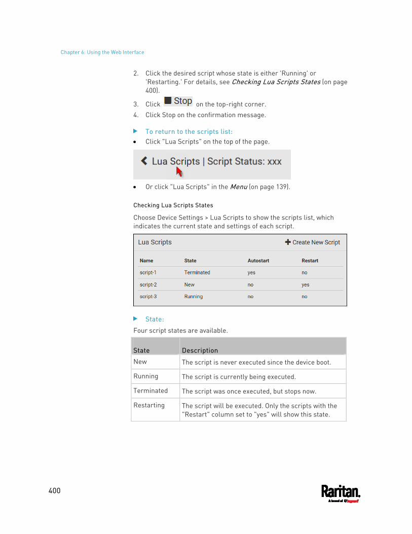
Chapter 6: Using the Web Interface
400
2. Click the desired script whose state is either 'Running' or 'Restarting.' For details, see Checking Lua Scripts States (on page 400).
3. Click on the top-right corner. 4. Click Stop on the confirmation message.
To return to the scripts list: Click "Lua Scripts" on the top of the page.
Or click "Lua Scripts" in the Menu (on page 139).
Checking Lua Scripts States
Choose Device Settings > Lua Scripts to show the scripts list, which indicates the current state and settings of each script.
State:
Four script states are available.
State Description
New The script is never executed since the device boot.
Running The script is currently being executed.
Terminated The script was once executed, but stops now.
Restarting The script will be executed. Only the scripts with the "Restart" column set to "yes" will show this state.
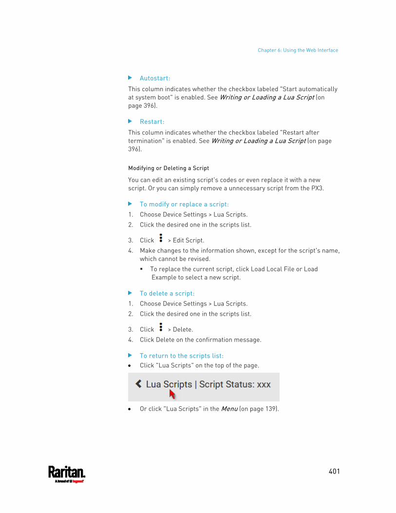
Chapter 6: Using the Web Interface
401
Autostart:
This column indicates whether the checkbox labeled "Start automatically at system boot" is enabled. See Writing or Loading a Lua Script (on page 396).
Restart:
This column indicates whether the checkbox labeled "Restart after termination" is enabled. See Writing or Loading a Lua Script (on page 396).
Modifying or Deleting a Script
You can edit an existing script's codes or even replace it with a new script. Or you can simply remove a unnecessary script from the PX3.
To modify or replace a script: 1. Choose Device Settings > Lua Scripts. 2. Click the desired one in the scripts list.
3. Click > Edit Script. 4. Make changes to the information shown, except for the script's name,
which cannot be revised. To replace the current script, click Load Local File or Load
Example to select a new script.
To delete a script: 1. Choose Device Settings > Lua Scripts. 2. Click the desired one in the scripts list.
3. Click > Delete. 4. Click Delete on the confirmation message.
To return to the scripts list: Click "Lua Scripts" on the top of the page.
Or click "Lua Scripts" in the Menu (on page 139).
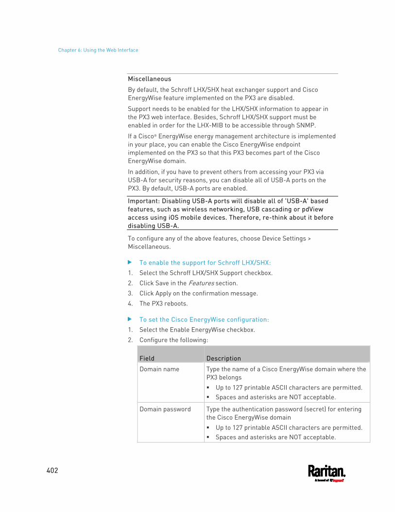
Chapter 6: Using the Web Interface
402
Miscellaneous
By default, the Schroff LHX/SHX heat exchanger support and Cisco EnergyWise feature implemented on the PX3 are disabled.
Support needs to be enabled for the LHX/SHX information to appear in the PX3 web interface. Besides, Schroff LHX/SHX support must be enabled in order for the LHX-MIB to be accessible through SNMP.
If a Cisco® EnergyWise energy management architecture is implemented in your place, you can enable the Cisco EnergyWise endpoint implemented on the PX3 so that this PX3 becomes part of the Cisco EnergyWise domain.
In addition, if you have to prevent others from accessing your PX3 via USB-A for security reasons, you can disable all of USB-A ports on the PX3. By default, USB-A ports are enabled.
Important: Disabling USB-A ports will disable all of 'USB-A' based features, such as wireless networking, USB cascading or pdView access using iOS mobile devices. Therefore, re-think about it before disabling USB-A.
To configure any of the above features, choose Device Settings > Miscellaneous.
To enable the support for Schroff LHX/SHX: 1. Select the Schroff LHX/SHX Support checkbox. 2. Click Save in the Features section. 3. Click Apply on the confirmation message. 4. The PX3 reboots.
To set the Cisco EnergyWise configuration: 1. Select the Enable EnergyWise checkbox. 2. Configure the following:
Field Description
Domain name Type the name of a Cisco EnergyWise domain where the PX3 belongs Up to 127 printable ASCII characters are permitted. Spaces and asterisks are NOT acceptable.
Domain password Type the authentication password (secret) for entering the Cisco EnergyWise domain Up to 127 printable ASCII characters are permitted. Spaces and asterisks are NOT acceptable.
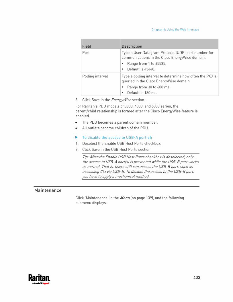
Chapter 6: Using the Web Interface
403
Field Description
Port Type a User Datagram Protocol (UDP) port number for communications in the Cisco EnergyWise domain. Range from 1 to 65535. Default is 43440.
Polling interval Type a polling interval to determine how often the PX3 is queried in the Cisco EnergyWise domain. Range from 30 to 600 ms. Default is 180 ms.
3. Click Save in the EnergyWise section.
For Raritan's PDU models of 3000, 4000, and 5000 series, the parent/child relationship is formed after the Cisco EnergyWise feature is enabled.
The PDU becomes a parent domain member. All outlets become children of the PDU.
To disable the access to USB-A port(s): 1. Deselect the Enable USB Host Ports checkbox. 2. Click Save in the USB Host Ports section.
Tip: After the Enable USB Host Ports checkbox is deselected, only the access to USB-A port(s) is prevented while the USB-B port works as normal. That is, users still can access the USB-B port, such as accessing CLI via USB-B. To disable the access to the USB-B port, you have to apply a mechanical method.
Maintenance
Click 'Maintenance' in the Menu (on page 139), and the following submenu displays.
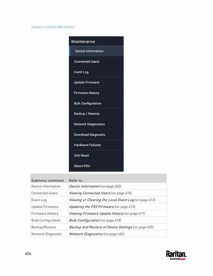
Chapter 6: Using the Web Interface
404
Submenu command Refer to...
Device Information Device Information (on page 405)
Connected Users Viewing Connected Users (on page 410)
Event Log Viewing or Clearing the Local Event Log (on page 412)
Update Firmware Updating the PX3 Firmware (on page 413)
Firmware History Viewing Firmware Update History (on page 417)
Bulk Configuration Bulk Configuration (on page 418)
Backup/Restore Backup and Restore of Device Settings (on page 425)
Network Diagnostic Network Diagnostics (on page 426)
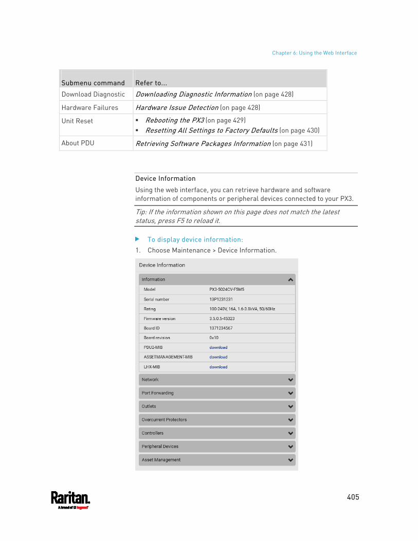
Chapter 6: Using the Web Interface
405
Submenu command Refer to...
Download Diagnostic Downloading Diagnostic Information (on page 428)
Hardware Failures Hardware Issue Detection (on page 428)
Unit Reset Rebooting the PX3 (on page 429) Resetting All Settings to Factory Defaults (on page 430)
About PDU Retrieving Software Packages Information (on page 431)
Device Information
Using the web interface, you can retrieve hardware and software information of components or peripheral devices connected to your PX3.
Tip: If the information shown on this page does not match the latest status, press F5 to reload it.
To display device information: 1. Choose Maintenance > Device Information.
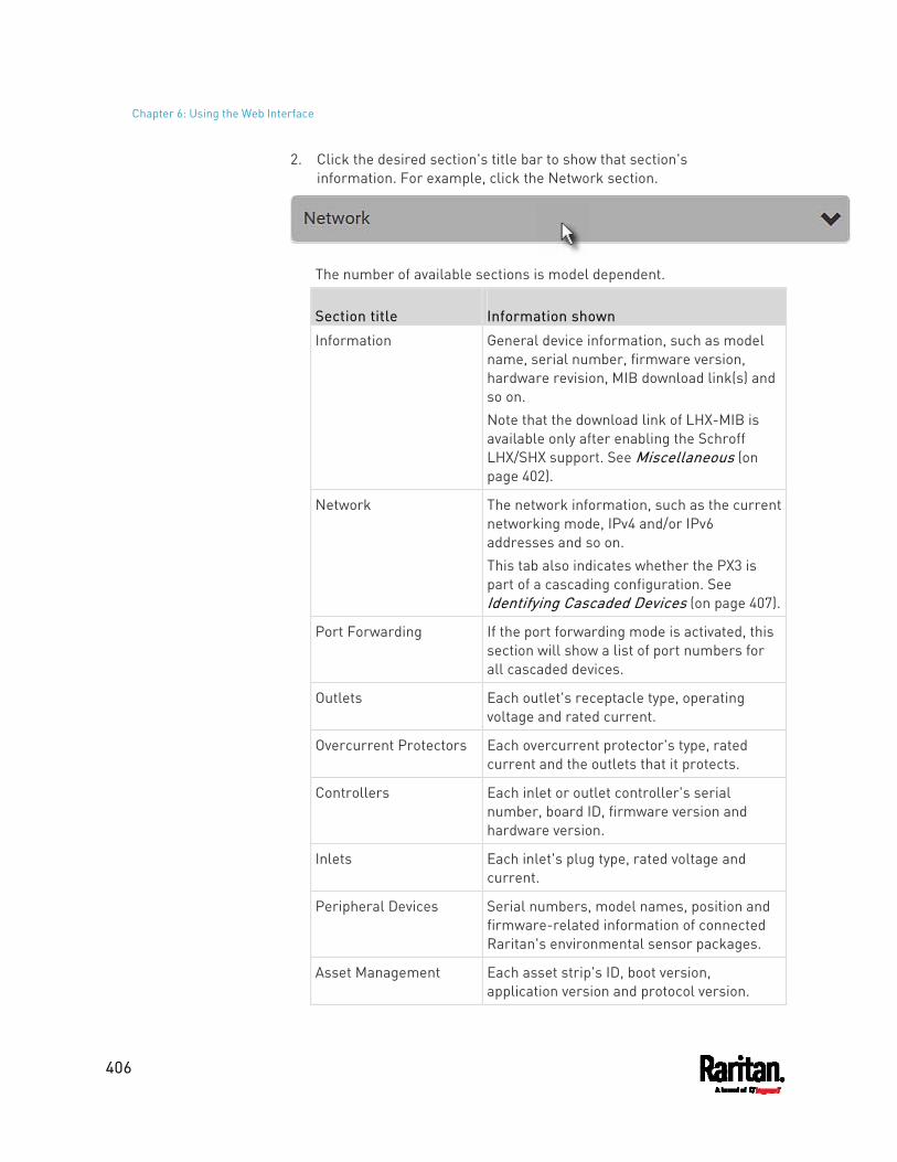
Chapter 6: Using the Web Interface
406
2. Click the desired section's title bar to show that section's information. For example, click the Network section.
The number of available sections is model dependent.
Section title Information shown
Information General device information, such as model name, serial number, firmware version, hardware revision, MIB download link(s) and so on. Note that the download link of LHX-MIB is available only after enabling the Schroff LHX/SHX support. See Miscellaneous (on page 402).
Network The network information, such as the current networking mode, IPv4 and/or IPv6 addresses and so on. This tab also indicates whether the PX3 is part of a cascading configuration. See Identifying Cascaded Devices (on page 407).
Port Forwarding If the port forwarding mode is activated, this section will show a list of port numbers for all cascaded devices.
Outlets Each outlet's receptacle type, operating voltage and rated current.
Overcurrent Protectors Each overcurrent protector's type, rated current and the outlets that it protects.
Controllers Each inlet or outlet controller's serial number, board ID, firmware version and hardware version.
Inlets Each inlet's plug type, rated voltage and current.
Peripheral Devices Serial numbers, model names, position and firmware-related information of connected Raritan's environmental sensor packages.
Asset Management Each asset strip's ID, boot version, application version and protocol version.
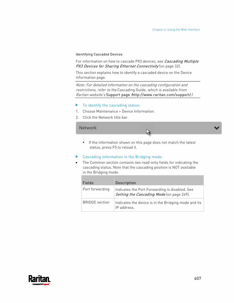
Chapter 6: Using the Web Interface
407
Identifying Cascaded Devices
For information on how to cascade PX3 devices, see Cascading Multiple PX3 Devices for Sharing Ethernet Connectivity (on page 32).
This section explains how to identify a cascaded device on the Device Information page.
Note: For detailed information on the cascading configuration and restrictions, refer to the Cascading Guide, which is available from Raritan website's Support page (http://www.raritan.com/support/).
To identify the cascading status: 1. Choose Maintenance > Device Information. 2. Click the Network title bar.
If the information shown on this page does not match the latest
status, press F5 to reload it.
Cascading information in the Bridging mode: The Common section contains two read-only fields for indicating the
cascading status. Note that the cascading position is NOT available in the Bridging mode.
Fields Description
Port forwarding Indicates the Port Forwarding is disabled. See Setting the Cascading Mode (on page 269).
BRIDGE section Indicates the device is in the Bridging mode and its IP address.
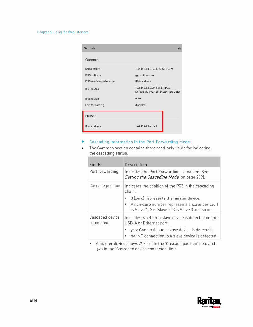
Chapter 6: Using the Web Interface
408
Cascading information in the Port Forwarding mode: The Common section contains three read-only fields for indicating
the cascading status.
Fields Description
Port forwarding Indicates the Port Forwarding is enabled. See Setting the Cascading Mode (on page 269).
Cascade position Indicates the position of the PX3 in the cascading chain.
0 (zero) represents the master device. A non-zero number represents a slave device. 1
is Slave 1, 2 is Slave 2, 3 is Slave 3 and so on.
Cascaded device connected
Indicates whether a slave device is detected on the USB-A or Ethernet port.
yes: Connection to a slave device is detected. no: NO connection to a slave device is detected.
A master device shows 0 (zero) in the 'Cascade position' field and yes in the 'Cascaded device connected' field.
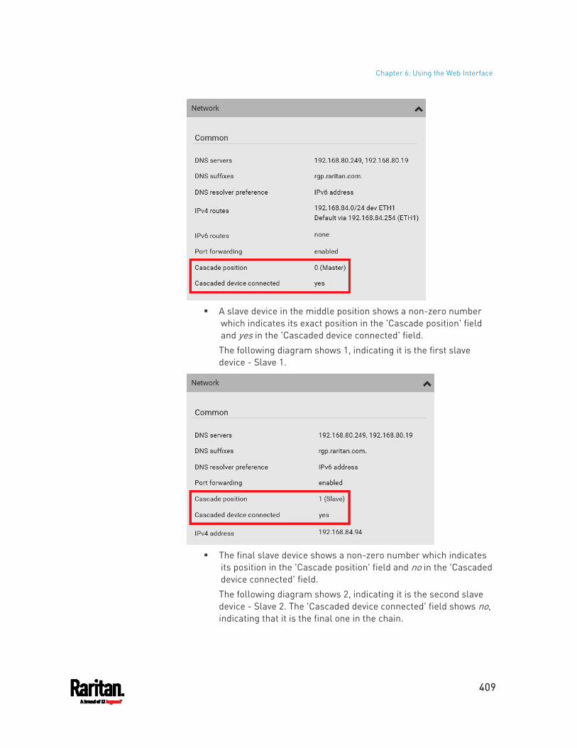
Chapter 6: Using the Web Interface
409
A slave device in the middle position shows a non-zero number
which indicates its exact position in the 'Cascade position' field and yes in the 'Cascaded device connected' field. The following diagram shows 1, indicating it is the first slave device - Slave 1.
The final slave device shows a non-zero number which indicates
its position in the 'Cascade position' field and no in the 'Cascaded device connected' field. The following diagram shows 2, indicating it is the second slave device - Slave 2. The 'Cascaded device connected' field shows no, indicating that it is the final one in the chain.
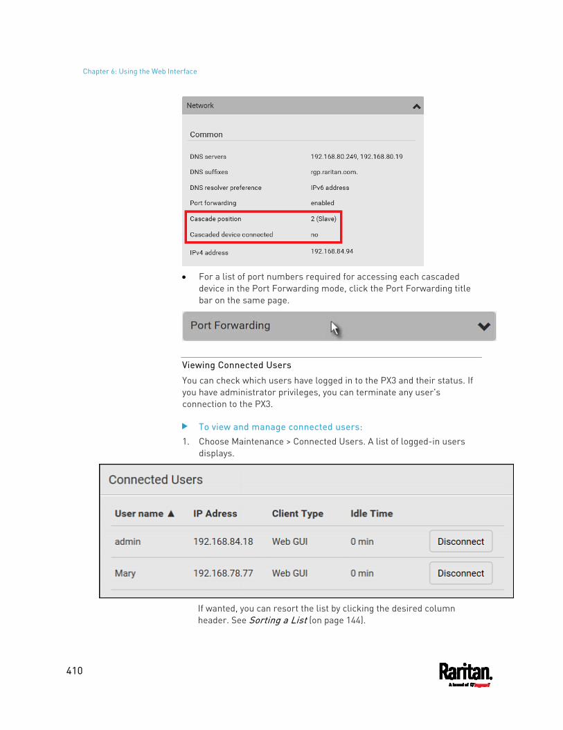
Chapter 6: Using the Web Interface
410
For a list of port numbers required for accessing each cascaded
device in the Port Forwarding mode, click the Port Forwarding title bar on the same page.
Viewing Connected Users
You can check which users have logged in to the PX3 and their status. If you have administrator privileges, you can terminate any user's connection to the PX3.
To view and manage connected users: 1. Choose Maintenance > Connected Users. A list of logged-in users
displays.
If wanted, you can resort the list by clicking the desired column header. See Sorting a List (on page 144).
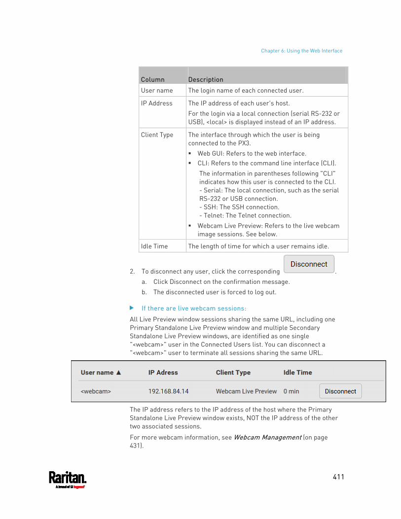
Chapter 6: Using the Web Interface
411
Column Description
User name The login name of each connected user.
IP Address The IP address of each user's host. For the login via a local connection (serial RS-232 or USB), <local> is displayed instead of an IP address.
Client Type The interface through which the user is being connected to the PX3. Web GUI: Refers to the web interface. CLI: Refers to the command line interface (CLI).
The information in parentheses following "CLI" indicates how this user is connected to the CLI. - Serial: The local connection, such as the serial RS-232 or USB connection. - SSH: The SSH connection. - Telnet: The Telnet connection.
Webcam Live Preview: Refers to the live webcam image sessions. See below.
Idle Time The length of time for which a user remains idle.
2. To disconnect any user, click the corresponding . a. Click Disconnect on the confirmation message. b. The disconnected user is forced to log out.
If there are live webcam sessions:
All Live Preview window sessions sharing the same URL, including one Primary Standalone Live Preview window and multiple Secondary Standalone Live Preview windows, are identified as one single "<webcam>" user in the Connected Users list. You can disconnect a "<webcam>" user to terminate all sessions sharing the same URL.
The IP address refers to the IP address of the host where the Primary Standalone Live Preview window exists, NOT the IP address of the other two associated sessions.
For more webcam information, see Webcam Management (on page 431).
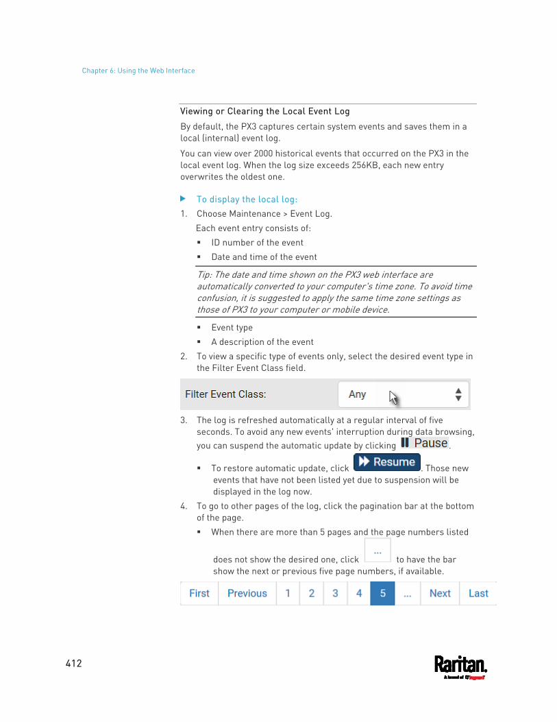
Chapter 6: Using the Web Interface
412
Viewing or Clearing the Local Event Log
By default, the PX3 captures certain system events and saves them in a local (internal) event log.
You can view over 2000 historical events that occurred on the PX3 in the local event log. When the log size exceeds 256KB, each new entry overwrites the oldest one.
To display the local log: 1. Choose Maintenance > Event Log.
Each event entry consists of: ID number of the event Date and time of the event
Tip: The date and time shown on the PX3 web interface are automatically converted to your computer's time zone. To avoid time confusion, it is suggested to apply the same time zone settings as those of PX3 to your computer or mobile device.
Event type A description of the event
2. To view a specific type of events only, select the desired event type in the Filter Event Class field.
3. The log is refreshed automatically at a regular interval of five
seconds. To avoid any new events' interruption during data browsing, you can suspend the automatic update by clicking .
To restore automatic update, click . Those new events that have not been listed yet due to suspension will be displayed in the log now.
4. To go to other pages of the log, click the pagination bar at the bottom of the page. When there are more than 5 pages and the page numbers listed
does not show the desired one, click to have the bar show the next or previous five page numbers, if available.
Chapter 6: Using the Web Interface
413
5. If wanted, you can resort the list by clicking the desired column header. See Sorting a List (on page 144).
To clear the local log:
1. Click on the top-right corner. 2. Click Clear Log on the confirmation message.
Updating the PX3 Firmware
Firmware files are available on Raritan website's Support page (http://www.raritan.com/support/).
When performing the firmware upgrade, the PX3 keeps each outlet's power status unchanged so no server operation is interrupted. During and after the firmware upgrade, outlets that have been powered on prior to the firmware upgrade remain powered ON and outlets that have been powered off remain powered OFF.
You must be the administrator or a user with the Firmware Update permission to update the PX3 firmware.
Before starting the upgrade, read the release notes downloaded from Raritan website's Support page (http://www.raritan.com/support/). If you have any questions or concerns about the upgrade, contact Raritan Technical Support BEFORE upgrading.
On a multi-inlet PDU, all inlets must be connected to power for the PDU to successfully upgrade its firmware.
Note that firmware upgrade via iOS mobile devices, such as iPad, requires the use of iCloud Drive or a file manager app.
Warning: Do NOT perform the firmware upgrade over a wireless network connection.
Firmware upgrade restrictions: Intermediate firmware required for upgrades from "pre-3.3.0" to
3.5.0 or later: If your PX3 is running any firmware version older than 3.3.0, such as 3.2.30, an intermediate firmware is required for the upgrade to 3.5.0 or later. Follow the sequence below: a. Upgrade to an intermediate firmware first, which is either 3.3.x
or 3.4.x. b. Then upgrade from the intermediate firmware to 3.5.0 or later.
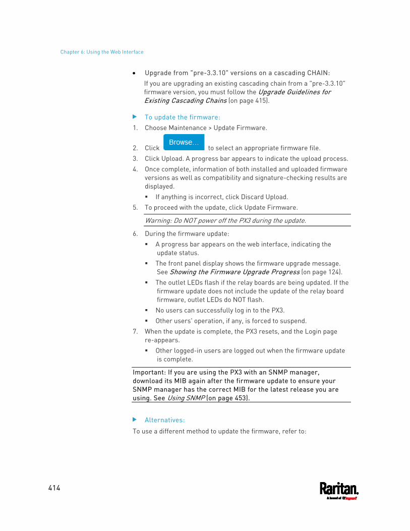
Chapter 6: Using the Web Interface
414
Upgrade from "pre-3.3.10" versions on a cascading CHAIN: If you are upgrading an existing cascading chain from a "pre-3.3.10" firmware version, you must follow the Upgrade Guidelines for Existing Cascading Chains (on page 415).
To update the firmware: 1. Choose Maintenance > Update Firmware.
2. Click to select an appropriate firmware file. 3. Click Upload. A progress bar appears to indicate the upload process. 4. Once complete, information of both installed and uploaded firmware
versions as well as compatibility and signature-checking results are displayed. If anything is incorrect, click Discard Upload.
5. To proceed with the update, click Update Firmware.
Warning: Do NOT power off the PX3 during the update.
6. During the firmware update: A progress bar appears on the web interface, indicating the
update status. The front panel display shows the firmware upgrade message.
See Showing the Firmware Upgrade Progress (on page 124). The outlet LEDs flash if the relay boards are being updated. If the
firmware update does not include the update of the relay board firmware, outlet LEDs do NOT flash.
No users can successfully log in to the PX3. Other users' operation, if any, is forced to suspend.
7. When the update is complete, the PX3 resets, and the Login page re-appears. Other logged-in users are logged out when the firmware update
is complete.
Important: If you are using the PX3 with an SNMP manager, download its MIB again after the firmware update to ensure your SNMP manager has the correct MIB for the latest release you are using. See Using SNMP (on page 453).
Alternatives:
To use a different method to update the firmware, refer to:
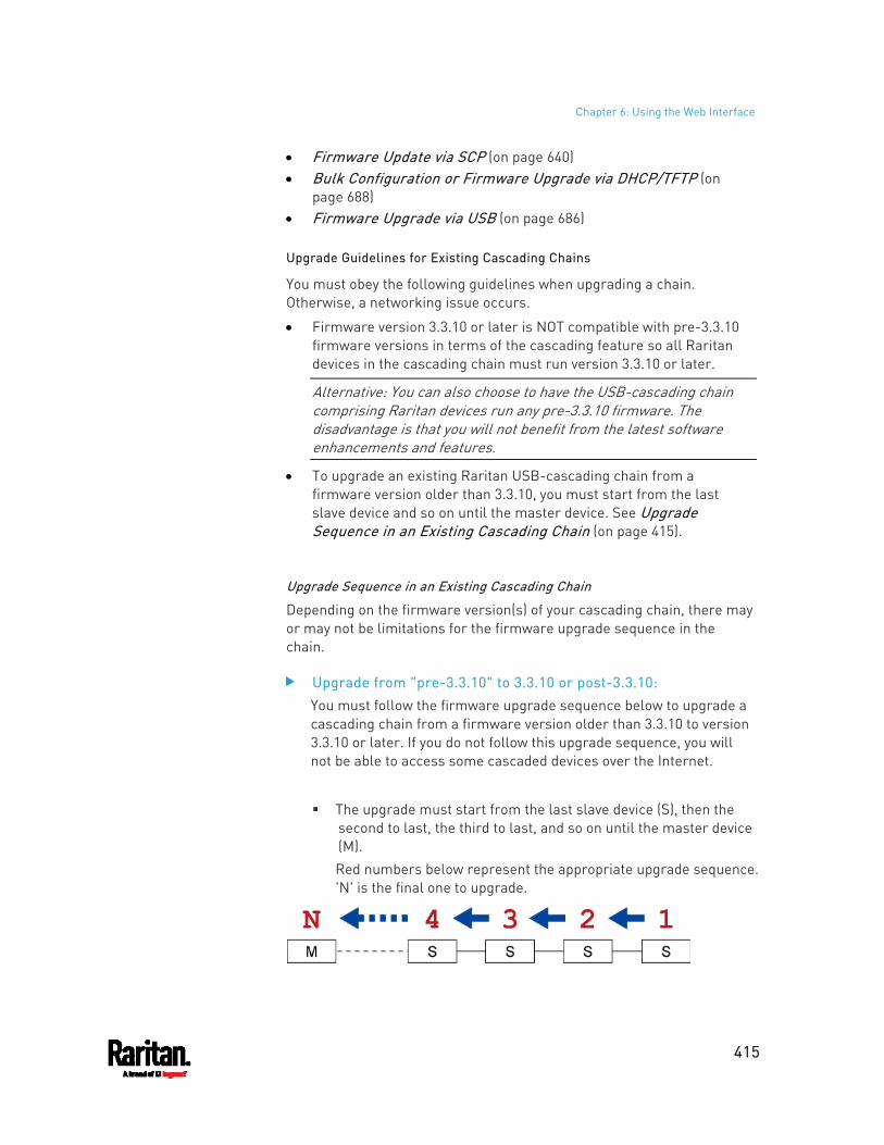
Chapter 6: Using the Web Interface
415
Firmware Update via SCP (on page 640) Bulk Configuration or Firmware Upgrade via DHCP/TFTP (on
page 688) Firmware Upgrade via USB (on page 686)
Upgrade Guidelines for Existing Cascading Chains
You must obey the following guidelines when upgrading a chain. Otherwise, a networking issue occurs.
Firmware version 3.3.10 or later is NOT compatible with pre-3.3.10 firmware versions in terms of the cascading feature so all Raritan devices in the cascading chain must run version 3.3.10 or later.
Alternative: You can also choose to have the USB-cascading chain comprising Raritan devices run any pre-3.3.10 firmware. The disadvantage is that you will not benefit from the latest software enhancements and features.
To upgrade an existing Raritan USB-cascading chain from a firmware version older than 3.3.10, you must start from the last slave device and so on until the master device. See Upgrade Sequence in an Existing Cascading Chain (on page 415).
Upgrade Sequence in an Existing Cascading Chain
Depending on the firmware version(s) of your cascading chain, there may or may not be limitations for the firmware upgrade sequence in the chain.
Upgrade from "pre-3.3.10" to 3.3.10 or post-3.3.10: You must follow the firmware upgrade sequence below to upgrade a cascading chain from a firmware version older than 3.3.10 to version 3.3.10 or later. If you do not follow this upgrade sequence, you will not be able to access some cascaded devices over the Internet.
The upgrade must start from the last slave device (S), then the second to last, the third to last, and so on until the master device (M). Red numbers below represent the appropriate upgrade sequence. 'N' is the final one to upgrade.
Chapter 6: Using the Web Interface
416
You must upgrade ALL devices in the chain to 3.3.10 or later. If you upgrade only some devices in the chain, networking issues occur on some cascaded devices.
Exception: A few products, such as PXC, are developed much later so they may not support older firmware versions, such as 3.4.0, 3.3.10, and so on. Therefore, it is suggested to AVOID downgrading your cascading chain unless instructed by Raritan or Legrand Technical Support.
Upgrade from 3.3.10 or post-3.3.10 to post-3.3.10: There is no upgrade sequence limitation. Firmware version 3.3.10 is compatible with later firmware versions so you can upgrade all devices of the chain in a random order.
Important: Raritan does not guarantee that no upgrade sequence limitation will be required for all future firmware versions. It is highly suggested to check the latest revision of the Cascading Guide or your product's User Guide/Online Help before performing the firmware upgrade. The other alternative is to always stick to the same sequence as the above diagram.
Downgrade from 3.3.10 to pre-3.3.10: There is no downgrade sequence limitation. However, firmware downgrade in a cascading chain is NOT recommended. Consult Raritan (or Legrand) Technical Support first if downgrade is needed. Firmware versions earlier than 3.3.10 are compatible with any pre-3.3.10 version so you can downgrade or upgrade all devices of the chain in a random order when all firmware versions in the chain are prior to version 3.3.10.
Note: It is suggested to always stick to the same sequence as the above diagram though there is no firmware downgrade limitation.
A Note about Firmware Upgrade Time
The PDU firmware upgrade time varies from unit to unit, depending on various external and internal factors.
Chapter 6: Using the Web Interface
417
External factors include, but are not limited to: network throughput, firmware file size, and speed at which the firmware is retrieved from the storage location. Internal factors include: the necessity of upgrading the firmware on the microcontroller and the number of microcontrollers that require upgrade (which depends on the number of outlets). The microcontroller is upgraded only when required. Therefore, the length of firmware upgrade time ranges from approximately 3 minutes (without any microcontroller updated) to almost 7 minutes (with all microcontrollers for 48 outlets updated). Take the above factors into account when estimating the PDU's firmware upgrade time.
The time indicated in this note is for PX3 web-interface-based upgrades. Upgrades through other management systems, such as Sunbird's Power IQ, may take additional time beyond the control of the PDU itself. This note does not address the upgrades using other management systems.
Full Disaster Recovery
For PX3 with iX7™ controller and PXC PDUs, disaster recovery can be performed via the USB connection only.
If the firmware upgrade fails, causing the PX3 to stop working, you can recover it by using a special utility rather than returning the device to Raritan.
Contact Raritan Technical Support for the recovery utility, which works in Windows XP/Vista/7/10 and Linux. In addition, an appropriate PX3 firmware file is required in the recovery procedure.
Note: For old PX3 without iX7™ controller, you can recover it via either a USB or serial RS-232 connection. See Old Generations of PX3 Models (on page 739).
Viewing Firmware Update History
The firmware upgrade history is permanently stored on the PX3. It remains available even though you perform a device reboot or any firmware update.
To view the firmware update history: 1. Choose Maintenance > Firmware History.
Each firmware update event consists of: Update date and time Previous firmware version Update firmware version Update result
Chapter 6: Using the Web Interface
418
2. If wanted, you can resort the list by clicking the desired column header. See Sorting a List (on page 144).
Bulk Configuration
The Bulk Configuration feature lets you save generic settings of a configured PX3 device to your computer. You can use this configuration file to copy common settings to other PX3 devices of the same model and firmware version. See Bulk Configuration Restrictions (on page 419).
A source device is the PX3 device where the configuration file is downloaded/saved. A target device is the PX3 device that loads the configuration file.
By default the configuration file downloaded from the source device contains settings based on the built-in bulk profile. The built-in bulk profile defines that all settings should be saved except for device-specific settings.
You can decide which settings are downloaded and which are not by creating your own bulk configuration profile.
Note that "device-specific" settings, such as the device's IP address or environmental sensor settings, will never be included into any profile you will create so they will never be downloaded from any source device. See Device-Specific Settings (on page 833).
When the date and time settings are included in the bulk configuration file, exercise caution when distributing that file to target devices located in a different time zone than the source device.
Tip: To back up or restore "all" settings, including device-specific ones, use the Backup/Restore feature instead. See Backup and Restore of Device Settings (on page 425).
Main bulk configuration procedure: 1. If you prefer customizing the bulk configuration file, create your own
bulk configuration profile(s) first. See Customizing Bulk Configuration Profiles (on page 421).
2. Perform the bulk configuration operation, which includes the following steps. For details, see Performing Bulk Configuration (on page 422). a. Make sure the desired bulk configuration profile has been
selected on the source device. b. Save a bulk configuration file from the source device. c. Perform bulk configuration on one or multiple target devices.
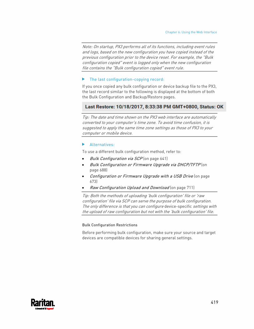
Chapter 6: Using the Web Interface
419
Note: On startup, PX3 performs all of its functions, including event rules and logs, based on the new configuration you have copied instead of the previous configuration prior to the device reset. For example, the "Bulk configuration copied" event is logged only when the new configuration file contains the "Bulk configuration copied" event rule.
The last configuration-copying record:
If you once copied any bulk configuration or device backup file to the PX3, the last record similar to the following is displayed at the bottom of both the Bulk Configuration and Backup/Restore pages.
Tip: The date and time shown on the PX3 web interface are automatically converted to your computer's time zone. To avoid time confusion, it is suggested to apply the same time zone settings as those of PX3 to your computer or mobile device.
Alternatives:
To use a different bulk configuration method, refer to:
Bulk Configuration via SCP (on page 641) Bulk Configuration or Firmware Upgrade via DHCP/TFTP (on
page 688) Configuration or Firmware Upgrade with a USB Drive (on page
673) Raw Configuration Upload and Download (on page 711)
Tip: Both the methods of uploading 'bulk configuration' file or 'raw configuration' file via SCP can serve the purpose of bulk configuration. The only difference is that you can configure device-specific settings with the upload of raw configuration but not with the 'bulk configuration' file.
Bulk Configuration Restrictions
Before performing bulk configuration, make sure your source and target devices are compatible devices for sharing general settings.
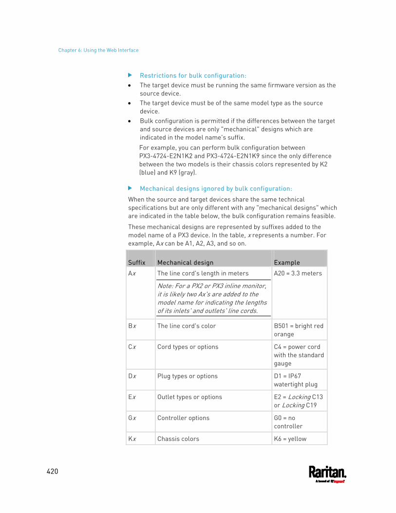
Chapter 6: Using the Web Interface
420
Restrictions for bulk configuration: The target device must be running the same firmware version as the
source device. The target device must be of the same model type as the source
device. Bulk configuration is permitted if the differences between the target
and source devices are only "mechanical" designs which are indicated in the model name's suffix. For example, you can perform bulk configuration between PX3-4724-E2N1K2 and PX3-4724-E2N1K9 since the only difference between the two models is their chassis colors represented by K2 (blue) and K9 (gray).
Mechanical designs ignored by bulk configuration:
When the source and target devices share the same technical specifications but are only different with any "mechanical designs" which are indicated in the table below, the bulk configuration remains feasible.
These mechanical designs are represented by suffixes added to the model name of a PX3 device. In the table, x represents a number. For example, Ax can be A1, A2, A3, and so on.
Suffix Mechanical design Example
Ax The line cord's length in meters
Note: For a PX2 or PX3 inline monitor, it is likely two Ax's are added to the model name for indicating the lengths of its inlets' and outlets' line cords.
A20 = 3.3 meters
Bx The line cord's color B501 = bright red orange
Cx Cord types or options C4 = power cord with the standard gauge
Dx Plug types or options D1 = IP67 watertight plug
Ex Outlet types or options E2 = Locking C13 or Locking C19
Gx Controller options G0 = no controller
Kx Chassis colors K6 = yellow
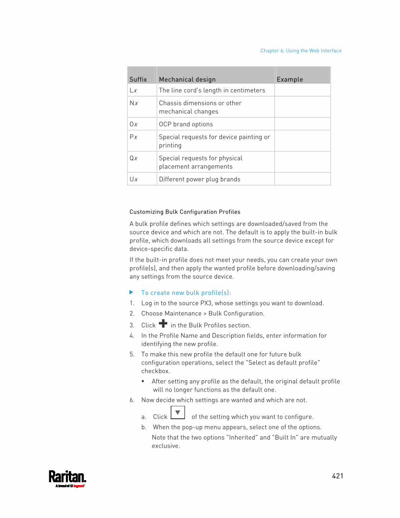
Chapter 6: Using the Web Interface
421
Suffix Mechanical design Example
Lx The line cord's length in centimeters
Nx Chassis dimensions or other mechanical changes
Ox OCP brand options
Px Special requests for device painting or printing
Qx Special requests for physical placement arrangements
Ux Different power plug brands
Customizing Bulk Configuration Profiles
A bulk profile defines which settings are downloaded/saved from the source device and which are not. The default is to apply the built-in bulk profile, which downloads all settings from the source device except for device-specific data.
If the built-in profile does not meet your needs, you can create your own profile(s), and then apply the wanted profile before downloading/saving any settings from the source device.
To create new bulk profile(s): 1. Log in to the source PX3, whose settings you want to download. 2. Choose Maintenance > Bulk Configuration.
3. Click in the Bulk Profiles section. 4. In the Profile Name and Description fields, enter information for
identifying the new profile. 5. To make this new profile the default one for future bulk
configuration operations, select the "Select as default profile" checkbox. After setting any profile as the default, the original default profile
will no longer functions as the default one. 6. Now decide which settings are wanted and which are not.
a. Click of the setting which you want to configure. b. When the pop-up menu appears, select one of the options.
Note that the two options "Inherited" and "Built In" are mutually exclusive.
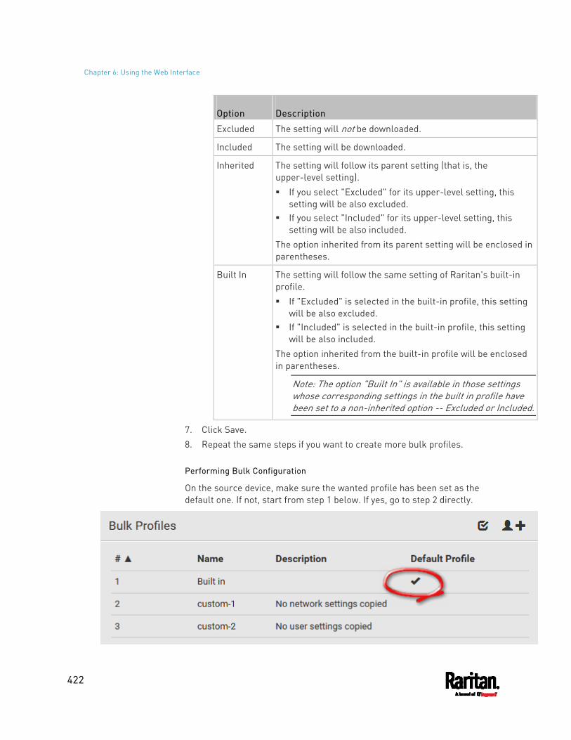
Chapter 6: Using the Web Interface
422
Option Description
Excluded The setting will not be downloaded.
Included The setting will be downloaded.
Inherited The setting will follow its parent setting (that is, the upper-level setting). If you select "Excluded" for its upper-level setting, this
setting will be also excluded. If you select "Included" for its upper-level setting, this
setting will be also included. The option inherited from its parent setting will be enclosed in parentheses.
Built In The setting will follow the same setting of Raritan's built-in profile. If "Excluded" is selected in the built-in profile, this setting
will be also excluded. If "Included" is selected in the built-in profile, this setting
will be also included. The option inherited from the built-in profile will be enclosed in parentheses.
Note: The option "Built In" is available in those settings whose corresponding settings in the built in profile have been set to a non-inherited option -- Excluded or Included.
7. Click Save. 8. Repeat the same steps if you want to create more bulk profiles.
Performing Bulk Configuration
On the source device, make sure the wanted profile has been set as the default one. If not, start from step 1 below. If yes, go to step 2 directly.
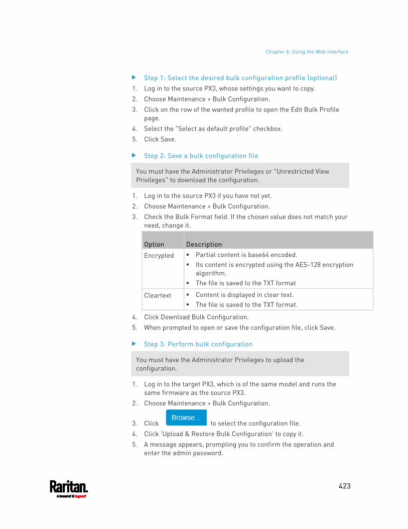
Chapter 6: Using the Web Interface
423
Step 1: Select the desired bulk configuration profile (optional) 1. Log in to the source PX3, whose settings you want to copy. 2. Choose Maintenance > Bulk Configuration. 3. Click on the row of the wanted profile to open the Edit Bulk Profile
page. 4. Select the "Select as default profile" checkbox. 5. Click Save.
Step 2: Save a bulk configuration file
You must have the Administrator Privileges or "Unrestricted View Privileges" to download the configuration.
1. Log in to the source PX3 if you have not yet. 2. Choose Maintenance > Bulk Configuration. 3. Check the Bulk Format field. If the chosen value does not match your
need, change it.
Option Description
Encrypted Partial content is base64 encoded. Its content is encrypted using the AES-128 encryption
algorithm. The file is saved to the TXT format
Cleartext Content is displayed in clear text. The file is saved to the TXT format.
4. Click Download Bulk Configuration. 5. When prompted to open or save the configuration file, click Save.
Step 3: Perform bulk configuration
You must have the Administrator Privileges to upload the configuration.
1. Log in to the target PX3, which is of the same model and runs the same firmware as the source PX3.
2. Choose Maintenance > Bulk Configuration.
3. Click to select the configuration file. 4. Click 'Upload & Restore Bulk Configuration' to copy it. 5. A message appears, prompting you to confirm the operation and
enter the admin password.
Chapter 6: Using the Web Interface
424
Enter the admin password, and click Restore. 6. Wait until the PX3 resets and the login page re-appears.
Alternatives:
To use a different bulk configuration method, refer to:
Bulk Configuration via SCP (on page 641) Bulk Configuration or Firmware Upgrade via DHCP/TFTP (on
page 688) Configuration or Firmware Upgrade with a USB Drive (on page
673) Raw Configuration Upload and Download (on page 711)
Tip: Both the methods of uploading 'bulk configuration' file or 'raw configuration' file via SCP can serve the purpose of bulk configuration. The only difference is that you can configure device-specific settings with the upload of raw configuration but not with the 'bulk configuration' file.
Modifying or Removing Bulk Profiles
You can modify or remove any bulk profile except for the built-in one.
Note that a profile that has been set as the default cannot be removed, either. To remove it, you have to remove its default setting first.
Choose Maintenance > Bulk Configuration. A list of profiles displays and then do one of the following.
To modify an existing profile: 1. Click on the row of the wanted profile in the list. 2. Change the settings you want. 3. Click Save.
To remove a single profile: 1. Click on the row of the wanted profile.
2. Click on the top-right corner. 3. Click Delete on the confirmation message.
To remove one or multiple profiles:
1. Click to make checkboxes appear in front of profiles. 2. Select one or multiple profiles.
To select ALL profiles, select the topmost checkbox in the header row.
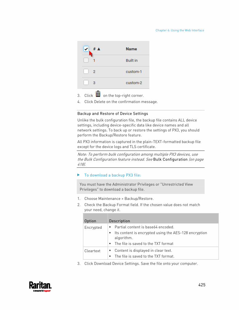
Chapter 6: Using the Web Interface
425
3. Click on the top-right corner. 4. Click Delete on the confirmation message.
Backup and Restore of Device Settings
Unlike the bulk configuration file, the backup file contains ALL device settings, including device-specific data like device names and all network settings. To back up or restore the settings of PX3, you should perform the Backup/Restore feature.
All PX3 information is captured in the plain-TEXT-formatted backup file except for the device logs and TLS certificate.
Note: To perform bulk configuration among multiple PX3 devices, use the Bulk Configuration feature instead. See Bulk Configuration (on page 418).
To download a backup PX3 file:
You must have the Administrator Privileges or "Unrestricted View Privileges" to download a backup file.
1. Choose Maintenance > Backup/Restore. 2. Check the Backup Format field. If the chosen value does not match
your need, change it.
Option Description
Encrypted Partial content is base64 encoded. Its content is encrypted using the AES-128 encryption
algorithm. The file is saved to the TXT format
Cleartext Content is displayed in clear text. The file is saved to the TXT format.
3. Click Download Device Settings. Save the file onto your computer.
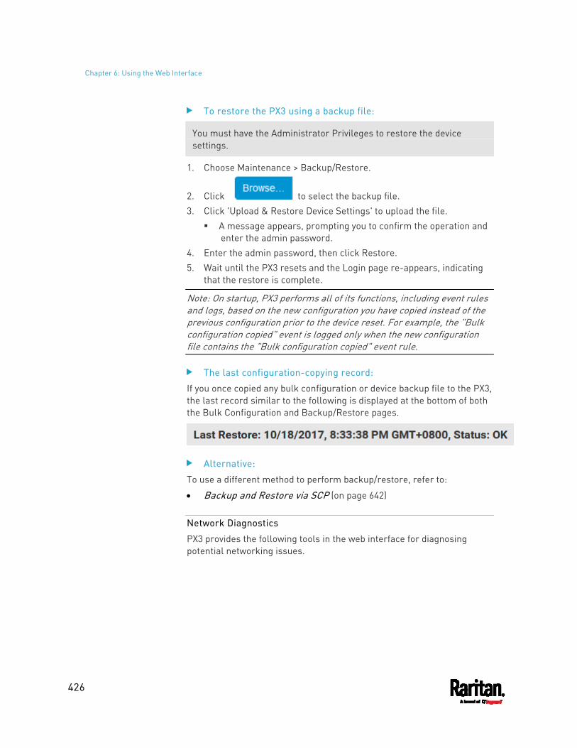
Chapter 6: Using the Web Interface
426
To restore the PX3 using a backup file:
You must have the Administrator Privileges to restore the device settings.
1. Choose Maintenance > Backup/Restore.
2. Click to select the backup file. 3. Click 'Upload & Restore Device Settings' to upload the file.
A message appears, prompting you to confirm the operation and enter the admin password.
4. Enter the admin password, then click Restore. 5. Wait until the PX3 resets and the Login page re-appears, indicating
that the restore is complete.
Note: On startup, PX3 performs all of its functions, including event rules and logs, based on the new configuration you have copied instead of the previous configuration prior to the device reset. For example, the "Bulk configuration copied" event is logged only when the new configuration file contains the "Bulk configuration copied" event rule.
The last configuration-copying record:
If you once copied any bulk configuration or device backup file to the PX3, the last record similar to the following is displayed at the bottom of both the Bulk Configuration and Backup/Restore pages.
Alternative:
To use a different method to perform backup/restore, refer to:
Backup and Restore via SCP (on page 642)
Network Diagnostics
PX3 provides the following tools in the web interface for diagnosing potential networking issues.
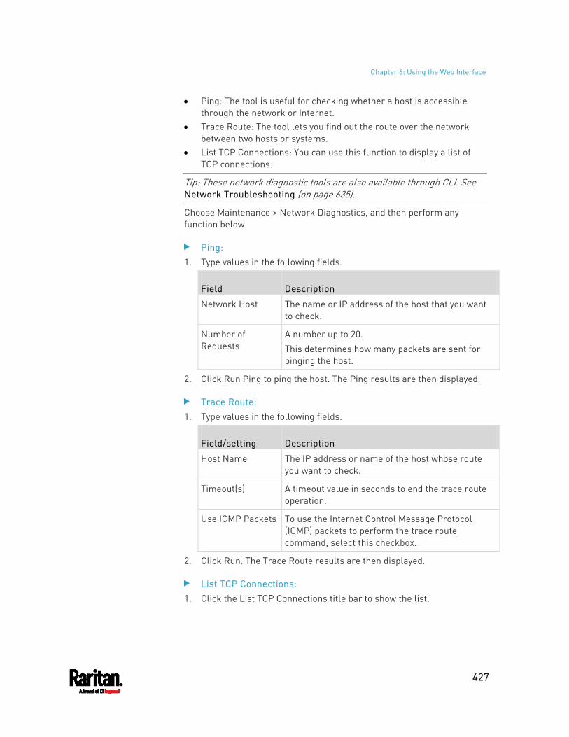
Chapter 6: Using the Web Interface
427
Ping: The tool is useful for checking whether a host is accessible through the network or Internet.
Trace Route: The tool lets you find out the route over the network between two hosts or systems.
List TCP Connections: You can use this function to display a list of TCP connections.
Tip: These network diagnostic tools are also available through CLI. See Network Troubleshooting (on page 635).
Choose Maintenance > Network Diagnostics, and then perform any function below.
Ping: 1. Type values in the following fields.
Field Description
Network Host The name or IP address of the host that you want to check.
Number of Requests
A number up to 20. This determines how many packets are sent for pinging the host.
2. Click Run Ping to ping the host. The Ping results are then displayed.
Trace Route: 1. Type values in the following fields.
Field/setting Description
Host Name The IP address or name of the host whose route you want to check.
Timeout(s) A timeout value in seconds to end the trace route operation.
Use ICMP Packets To use the Internet Control Message Protocol (ICMP) packets to perform the trace route command, select this checkbox.
2. Click Run. The Trace Route results are then displayed.
List TCP Connections: 1. Click the List TCP Connections title bar to show the list.
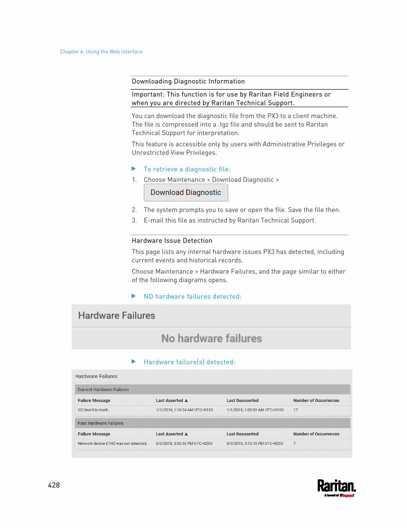
Chapter 6: Using the Web Interface
428
Downloading Diagnostic Information
Important: This function is for use by Raritan Field Engineers or when you are directed by Raritan Technical Support.
You can download the diagnostic file from the PX3 to a client machine. The file is compressed into a .tgz file and should be sent to Raritan Technical Support for interpretation.
This feature is accessible only by users with Administrative Privileges or Unrestricted View Privileges.
To retrieve a diagnostic file: 1. Choose Maintenance > Download Diagnostic >
. 2. The system prompts you to save or open the file. Save the file then. 3. E-mail this file as instructed by Raritan Technical Support.
Hardware Issue Detection
This page lists any internal hardware issues PX3 has detected, including current events and historical records.
Choose Maintenance > Hardware Failures, and the page similar to either of the following diagrams opens.
NO hardware failures detected:
Hardware failure(s) detected:
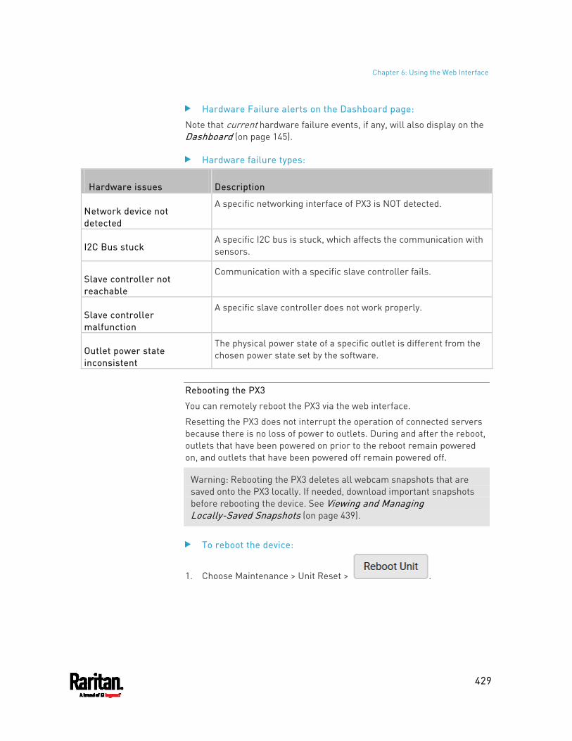
Chapter 6: Using the Web Interface
429
Hardware Failure alerts on the Dashboard page:
Note that current hardware failure events, if any, will also display on the Dashboard (on page 145).
Hardware failure types:
Hardware issues Description
Network device not detected
A specific networking interface of PX3 is NOT detected.
I2C Bus stuck A specific I2C bus is stuck, which affects the communication with sensors.
Slave controller not reachable
Communication with a specific slave controller fails.
Slave controller malfunction
A specific slave controller does not work properly.
Outlet power state inconsistent
The physical power state of a specific outlet is different from the chosen power state set by the software.
Rebooting the PX3
You can remotely reboot the PX3 via the web interface.
Resetting the PX3 does not interrupt the operation of connected servers because there is no loss of power to outlets. During and after the reboot, outlets that have been powered on prior to the reboot remain powered on, and outlets that have been powered off remain powered off.
Warning: Rebooting the PX3 deletes all webcam snapshots that are saved onto the PX3 locally. If needed, download important snapshots before rebooting the device. See Viewing and Managing Locally-Saved Snapshots (on page 439).
To reboot the device:
1. Choose Maintenance > Unit Reset > .
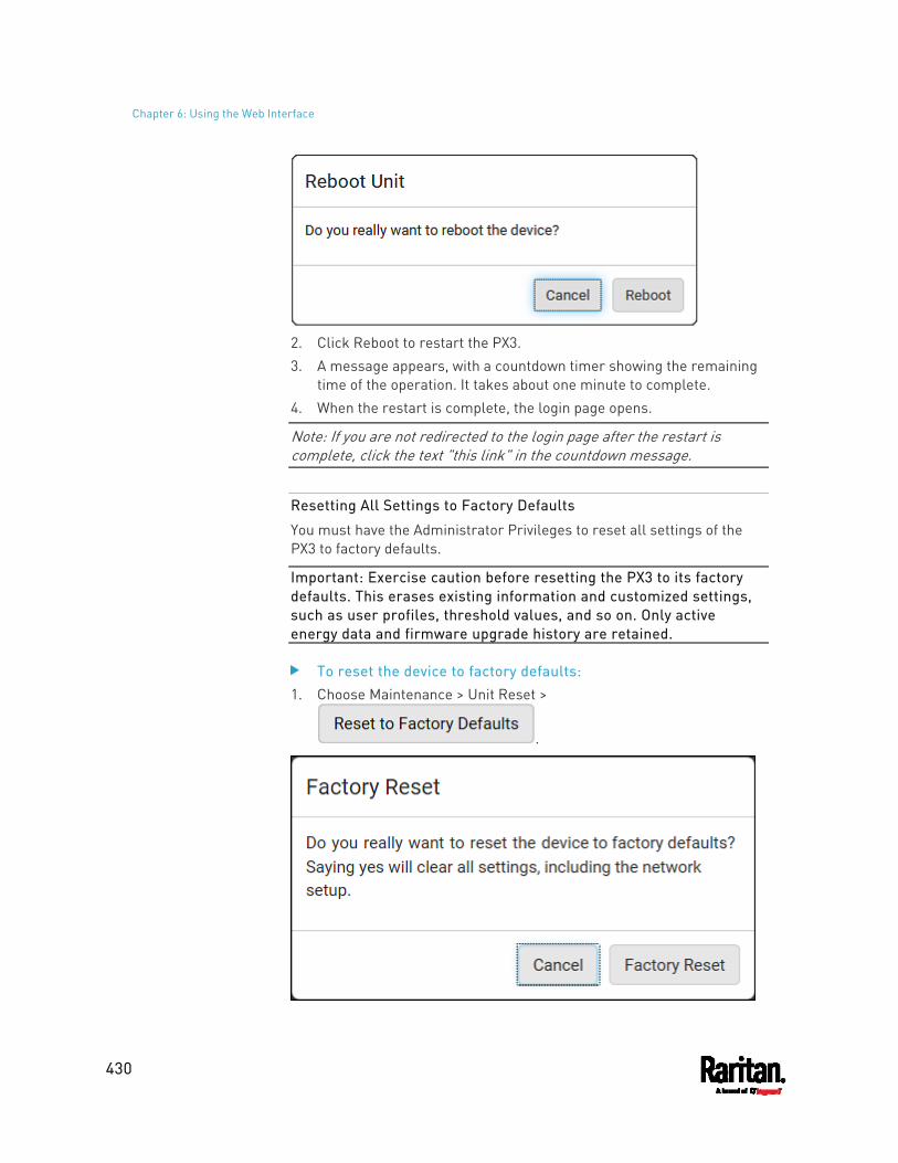
Chapter 6: Using the Web Interface
430
2. Click Reboot to restart the PX3. 3. A message appears, with a countdown timer showing the remaining
time of the operation. It takes about one minute to complete. 4. When the restart is complete, the login page opens.
Note: If you are not redirected to the login page after the restart is complete, click the text "this link" in the countdown message.
Resetting All Settings to Factory Defaults
You must have the Administrator Privileges to reset all settings of the PX3 to factory defaults.
Important: Exercise caution before resetting the PX3 to its factory defaults. This erases existing information and customized settings, such as user profiles, threshold values, and so on. Only active energy data and firmware upgrade history are retained.
To reset the device to factory defaults: 1. Choose Maintenance > Unit Reset >
.
Chapter 6: Using the Web Interface
431
2. Click Factory Reset to reset the PX3 to factory defaults. 3. A message appears, with a countdown timer showing the remaining
time of the operation. It takes about two minutes to complete. 4. When the reset is complete, the login page opens.
Note: If you are not redirected to the login page after the reset is complete, click the text "this link" in the countdown message.
Alternative:
There are two more methods to reset the device to factory defaults.
Use the "mechanical" reset button Perform the CLI command
For details, see Resetting to Factory Defaults (on page 717).
Retrieving Software Packages Information
You can check the current firmware version and the information of all open source packages embedded in the PX3 through the web interface.
To retrieve the embedded software packages information: 1. Choose Maintenance > About PDU. A list of open source packages is
displayed. 2. You can click any link to access related information or download any
software package.
Webcam Management
The 'Webcams' menu item appears when there is any webcam(s) connected to the PX3, or when there are snapshots saved onto the PX3 already. See Connecting a Logitech Webcam (on page 75).
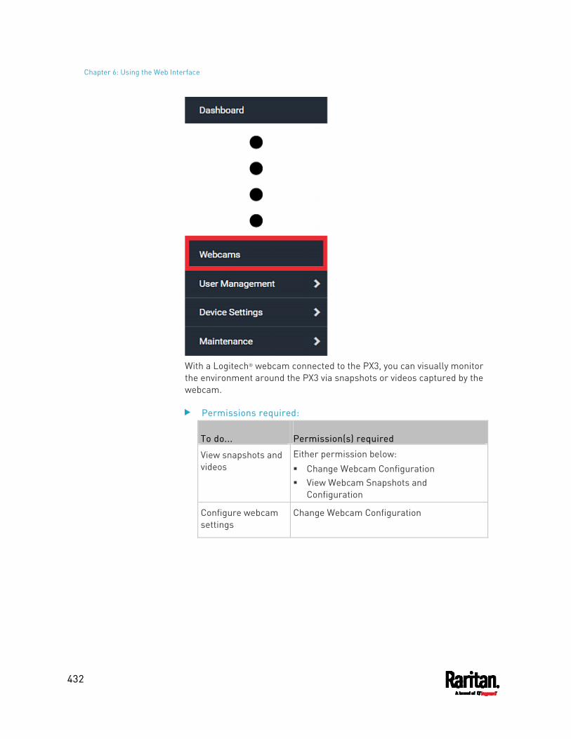
Chapter 6: Using the Web Interface
432
With a Logitech® webcam connected to the PX3, you can visually monitor the environment around the PX3 via snapshots or videos captured by the webcam.
Permissions required:
To do... Permission(s) required
View snapshots and videos
Either permission below: Change Webcam Configuration View Webcam Snapshots and
Configuration
Configure webcam settings
Change Webcam Configuration
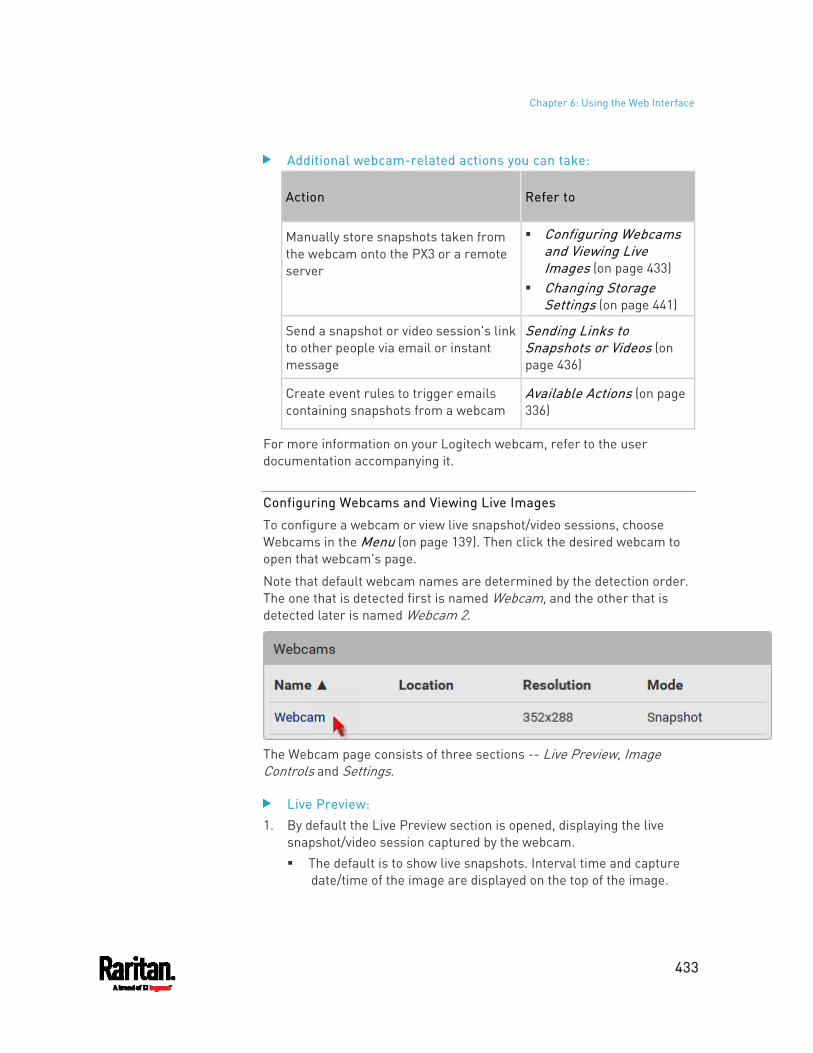
Chapter 6: Using the Web Interface
433
Additional webcam-related actions you can take:
Action Refer to
Manually store snapshots taken from the webcam onto the PX3 or a remote server
Configuring Webcams and Viewing Live Images (on page 433)
Changing Storage Settings (on page 441)
Send a snapshot or video session's link to other people via email or instant message
Sending Links to Snapshots or Videos (on page 436)
Create event rules to trigger emails containing snapshots from a webcam
Available Actions (on page 336)
For more information on your Logitech webcam, refer to the user documentation accompanying it.
Configuring Webcams and Viewing Live Images
To configure a webcam or view live snapshot/video sessions, choose Webcams in the Menu (on page 139). Then click the desired webcam to open that webcam's page.
Note that default webcam names are determined by the detection order. The one that is detected first is named Webcam, and the other that is detected later is named Webcam 2.
The Webcam page consists of three sections -- Live Preview, Image Controls and Settings.
Live Preview: 1. By default the Live Preview section is opened, displaying the live
snapshot/video session captured by the webcam. The default is to show live snapshots. Interval time and capture
date/time of the image are displayed on the top of the image.
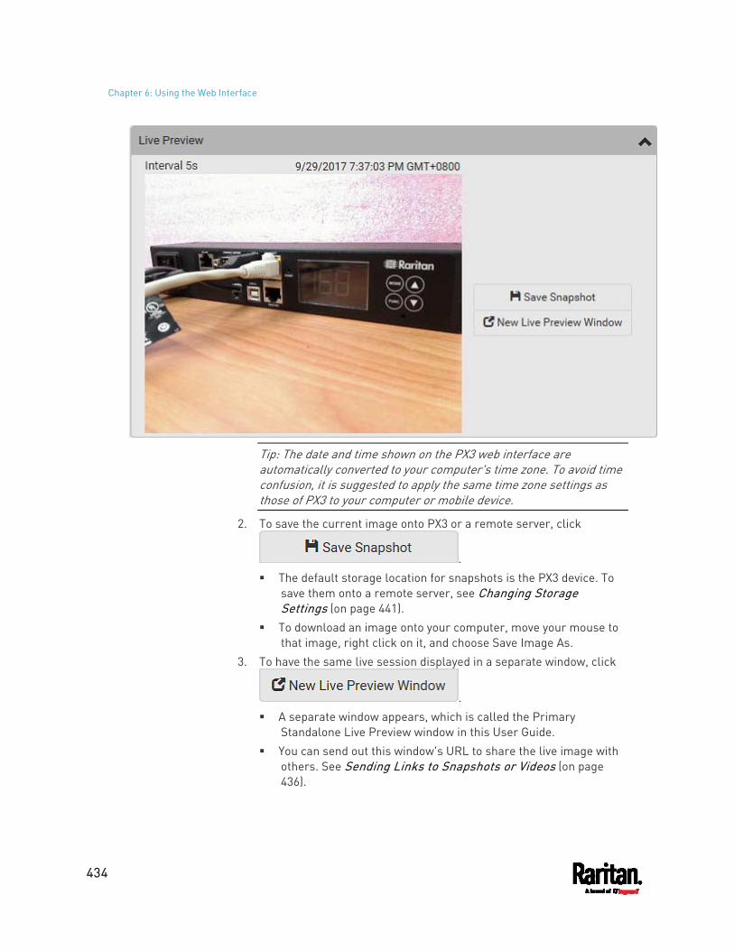
Chapter 6: Using the Web Interface
434
Tip: The date and time shown on the PX3 web interface are automatically converted to your computer's time zone. To avoid time confusion, it is suggested to apply the same time zone settings as those of PX3 to your computer or mobile device.
2. To save the current image onto PX3 or a remote server, click
. The default storage location for snapshots is the PX3 device. To
save them onto a remote server, see Changing Storage Settings (on page 441).
To download an image onto your computer, move your mouse to that image, right click on it, and choose Save Image As.
3. To have the same live session displayed in a separate window, click
. A separate window appears, which is called the Primary
Standalone Live Preview window in this User Guide. You can send out this window's URL to share the live image with
others. See Sending Links to Snapshots or Videos (on page 436).
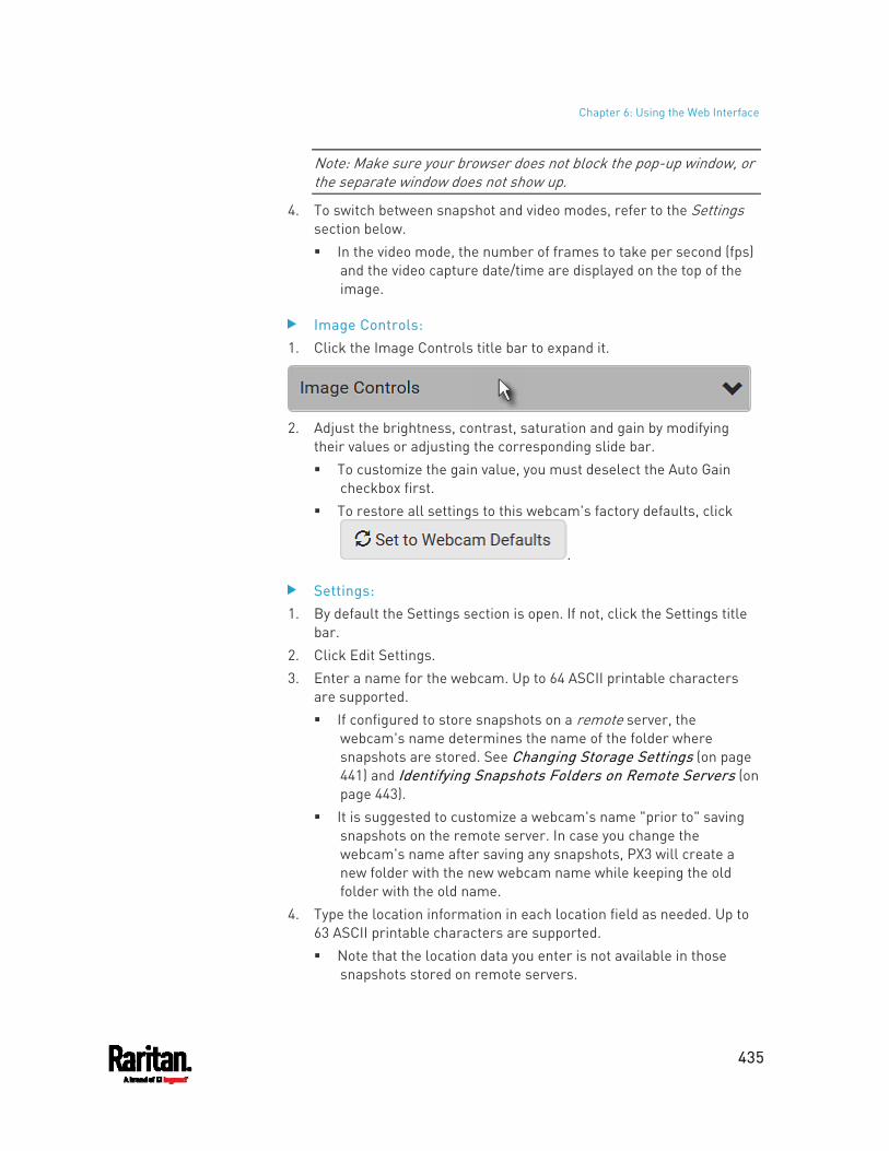
Chapter 6: Using the Web Interface
435
Note: Make sure your browser does not block the pop-up window, or the separate window does not show up.
4. To switch between snapshot and video modes, refer to the Settings section below. In the video mode, the number of frames to take per second (fps)
and the video capture date/time are displayed on the top of the image.
Image Controls: 1. Click the Image Controls title bar to expand it.
2. Adjust the brightness, contrast, saturation and gain by modifying
their values or adjusting the corresponding slide bar. To customize the gain value, you must deselect the Auto Gain
checkbox first. To restore all settings to this webcam's factory defaults, click
.
Settings: 1. By default the Settings section is open. If not, click the Settings title
bar. 2. Click Edit Settings. 3. Enter a name for the webcam. Up to 64 ASCII printable characters
are supported. If configured to store snapshots on a remote server, the
webcam's name determines the name of the folder where snapshots are stored. See Changing Storage Settings (on page 441) and Identifying Snapshots Folders on Remote Servers (on page 443).
It is suggested to customize a webcam's name "prior to" saving snapshots on the remote server. In case you change the webcam's name after saving any snapshots, PX3 will create a new folder with the new webcam name while keeping the old folder with the old name.
4. Type the location information in each location field as needed. Up to 63 ASCII printable characters are supported. Note that the location data you enter is not available in those
snapshots stored on remote servers.
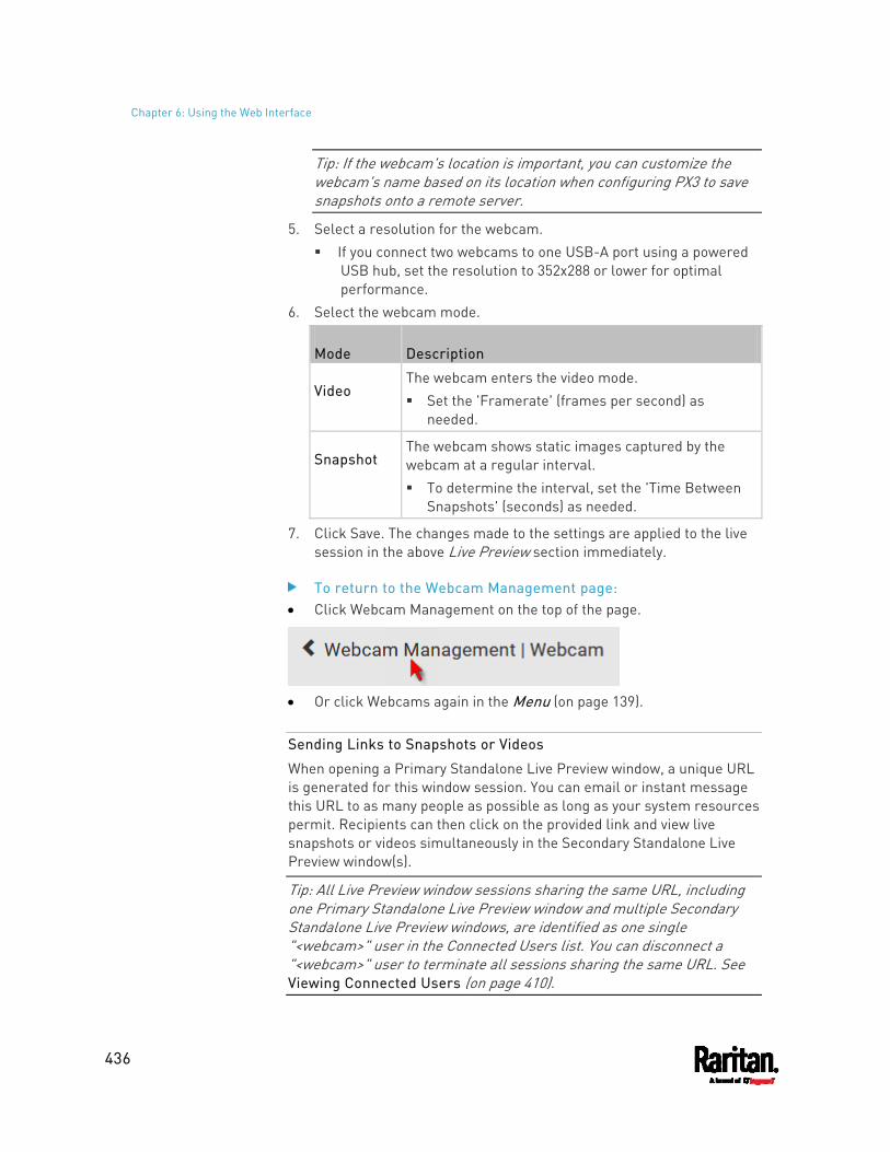
Chapter 6: Using the Web Interface
436
Tip: If the webcam's location is important, you can customize the webcam's name based on its location when configuring PX3 to save snapshots onto a remote server.
5. Select a resolution for the webcam. If you connect two webcams to one USB-A port using a powered
USB hub, set the resolution to 352x288 or lower for optimal performance.
6. Select the webcam mode.
Mode Description
Video The webcam enters the video mode. Set the 'Framerate' (frames per second) as
needed.
Snapshot The webcam shows static images captured by the webcam at a regular interval. To determine the interval, set the 'Time Between
Snapshots' (seconds) as needed.
7. Click Save. The changes made to the settings are applied to the live session in the above Live Preview section immediately.
To return to the Webcam Management page: Click Webcam Management on the top of the page.
Or click Webcams again in the Menu (on page 139).
Sending Links to Snapshots or Videos
When opening a Primary Standalone Live Preview window, a unique URL is generated for this window session. You can email or instant message this URL to as many people as possible as long as your system resources permit. Recipients can then click on the provided link and view live snapshots or videos simultaneously in the Secondary Standalone Live Preview window(s).
Tip: All Live Preview window sessions sharing the same URL, including one Primary Standalone Live Preview window and multiple Secondary Standalone Live Preview windows, are identified as one single "<webcam>" user in the Connected Users list. You can disconnect a "<webcam>" user to terminate all sessions sharing the same URL. See Viewing Connected Users (on page 410).
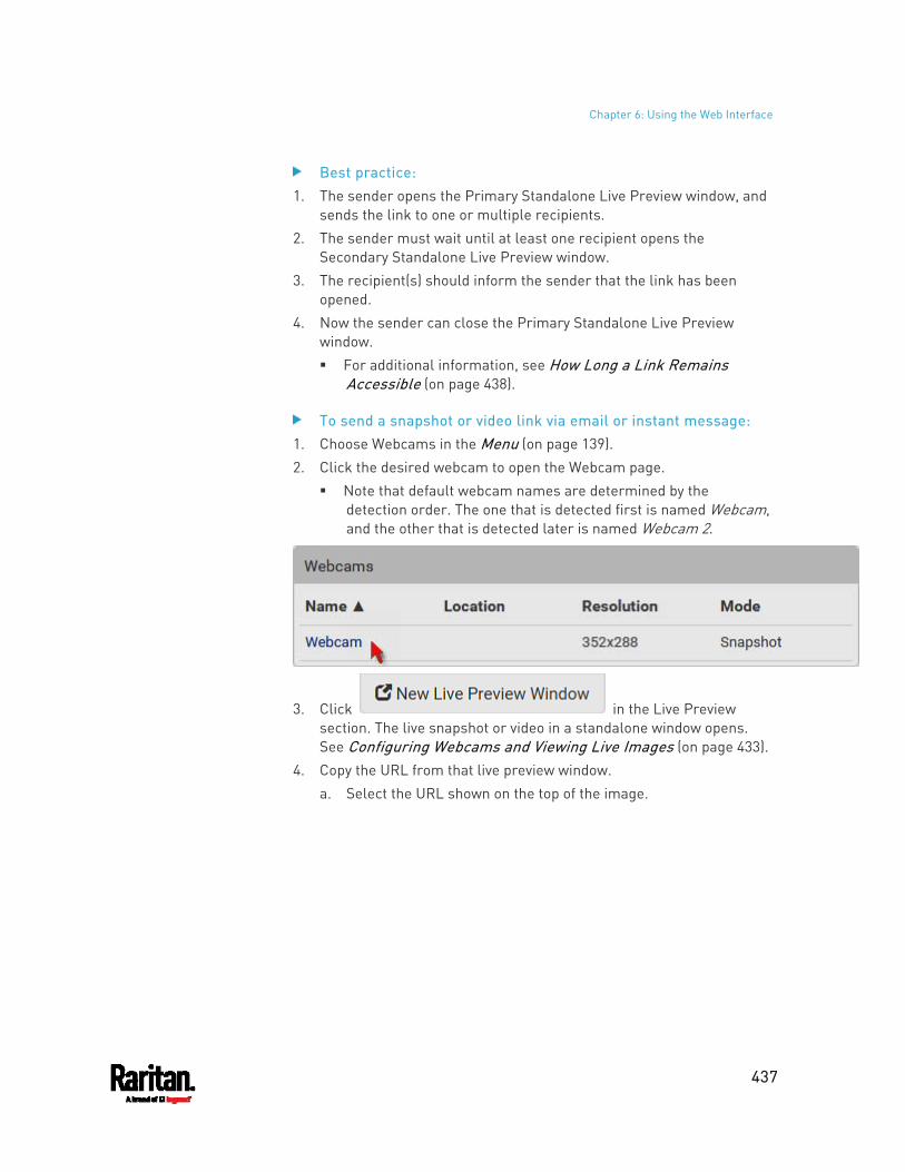
Chapter 6: Using the Web Interface
437
Best practice: 1. The sender opens the Primary Standalone Live Preview window, and
sends the link to one or multiple recipients. 2. The sender must wait until at least one recipient opens the
Secondary Standalone Live Preview window. 3. The recipient(s) should inform the sender that the link has been
opened. 4. Now the sender can close the Primary Standalone Live Preview
window. For additional information, see How Long a Link Remains
Accessible (on page 438).
To send a snapshot or video link via email or instant message: 1. Choose Webcams in the Menu (on page 139). 2. Click the desired webcam to open the Webcam page.
Note that default webcam names are determined by the detection order. The one that is detected first is named Webcam, and the other that is detected later is named Webcam 2.
3. Click in the Live Preview section. The live snapshot or video in a standalone window opens. See Configuring Webcams and Viewing Live Images (on page 433).
4. Copy the URL from that live preview window. a. Select the URL shown on the top of the image.
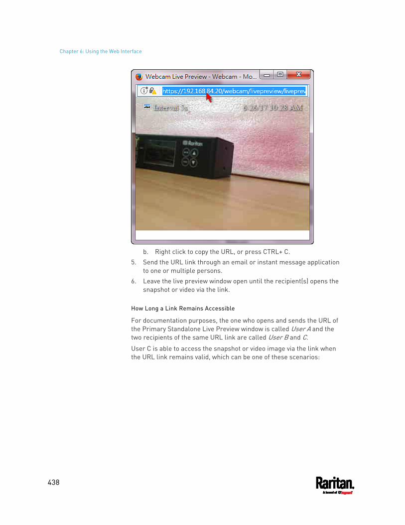
Chapter 6: Using the Web Interface
438
b. Right click to copy the URL, or press CTRL+ C.
5. Send the URL link through an email or instant message application to one or multiple persons.
6. Leave the live preview window open until the recipient(s) opens the snapshot or video via the link.
How Long a Link Remains Accessible
For documentation purposes, the one who opens and sends the URL of the Primary Standalone Live Preview window is called User A and the two recipients of the same URL link are called User B and C.
User C is able to access the snapshot or video image via the link when the URL link remains valid, which can be one of these scenarios:
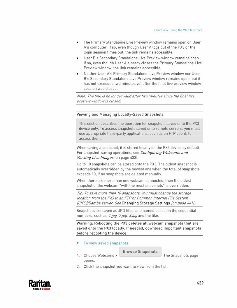
Chapter 6: Using the Web Interface
439
The Primary Standalone Live Preview window remains open on User A's computer. If so, even though User A logs out of the PX3 or the login session times out, the link remains accessible.
User B's Secondary Standalone Live Preview window remains open. If so, even though User A already closes the Primary Standalone Live Preview window, the link remains accessible.
Neither User A's Primary Standalone Live Preview window nor User B's Secondary Standalone Live Preview window remains open, but it has not exceeded two minutes yet after the final live preview window session was closed.
Note: The link is no longer valid after two minutes since the final live preview window is closed.
Viewing and Managing Locally-Saved Snapshots
This section describes the operation for snapshots saved onto the PX3 device only. To access snapshots saved onto remote servers, you must use appropriate third-party applications, such as an FTP client, to access them.
When saving a snapshot, it is stored locally on the PX3 device by default. For snapshot-saving operations, see Configuring Webcams and Viewing Live Images (on page 433).
Up to 10 snapshots can be stored onto the PX3. The oldest snapshot is automatically overridden by the newest one when the total of snapshots exceeds 10, if no snapshots are deleted manually.
When there are more than one webcam connected, then the oldest snapshot of the webcam "with the most snapshots" is overridden.
Tip: To save more than 10 snapshots, you must change the storage location from the PX3 to an FTP or Common Internet File System (CIFS)/Samba server. See Changing Storage Settings (on page 441).
Snapshots are saved as JPG files, and named based on the sequential numbers, such as 1.jpg, 2.jpg, 3.jpg and the like.
Warning: Rebooting the PX3 deletes all webcam snapshots that are saved onto the PX3 locally. If needed, download important snapshots before rebooting the device.
To view saved snapshots:
1. Choose Webcams > . The Snapshots page opens.
2. Click the snapshot you want to view from the list.
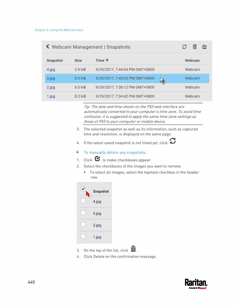
Chapter 6: Using the Web Interface
440
Tip: The date and time shown on the PX3 web interface are automatically converted to your computer's time zone. To avoid time confusion, it is suggested to apply the same time zone settings as those of PX3 to your computer or mobile device.
3. The selected snapshot as well as its information, such as captured time and resolution, is displayed on the same page.
4. If the latest saved snapshot is not listed yet, click .
To manually delete any snapshots:
1. Click to make checkboxes appear. 2. Select the checkboxes of the images you want to remove.
To select all images, select the topmost checkbox in the header row.
3. On the top of the list, click . 4. Click Delete on the confirmation message.
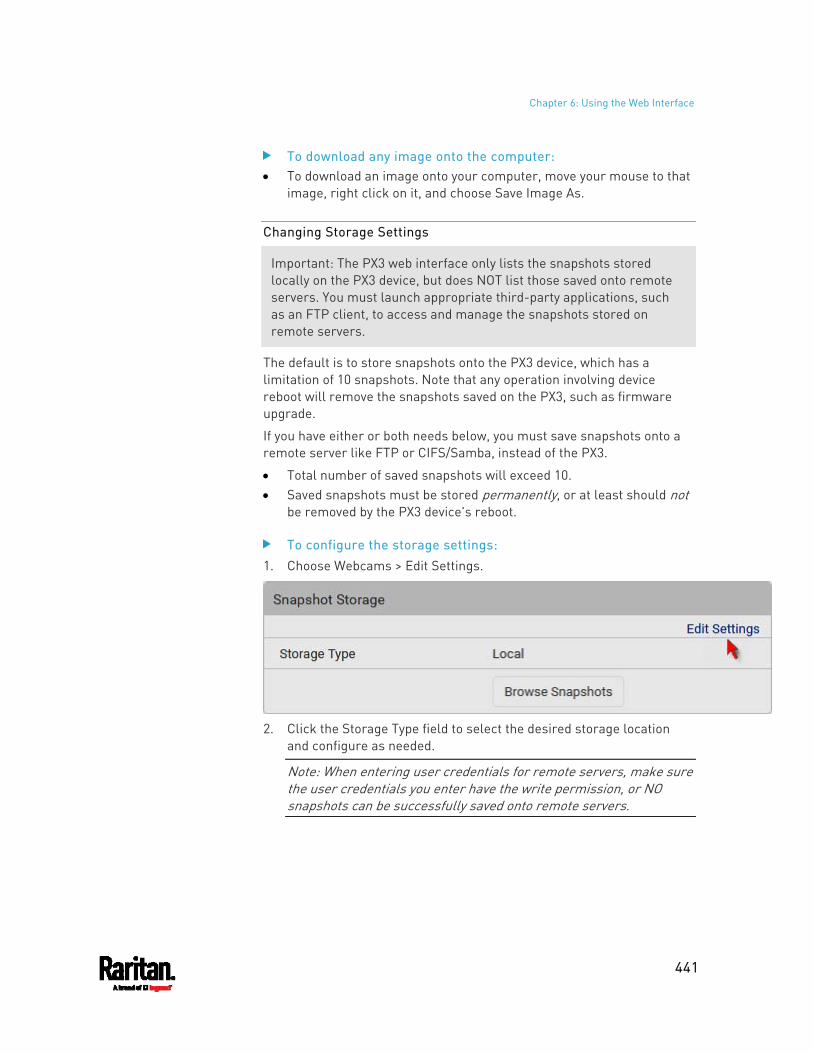
Chapter 6: Using the Web Interface
441
To download any image onto the computer: To download an image onto your computer, move your mouse to that
image, right click on it, and choose Save Image As.
Changing Storage Settings
Important: The PX3 web interface only lists the snapshots stored locally on the PX3 device, but does NOT list those saved onto remote servers. You must launch appropriate third-party applications, such as an FTP client, to access and manage the snapshots stored on remote servers.
The default is to store snapshots onto the PX3 device, which has a limitation of 10 snapshots. Note that any operation involving device reboot will remove the snapshots saved on the PX3, such as firmware upgrade.
If you have either or both needs below, you must save snapshots onto a remote server like FTP or CIFS/Samba, instead of the PX3.
Total number of saved snapshots will exceed 10. Saved snapshots must be stored permanently, or at least should not
be removed by the PX3 device's reboot.
To configure the storage settings: 1. Choose Webcams > Edit Settings.
2. Click the Storage Type field to select the desired storage location
and configure as needed.
Note: When entering user credentials for remote servers, make sure the user credentials you enter have the write permission, or NO snapshots can be successfully saved onto remote servers.
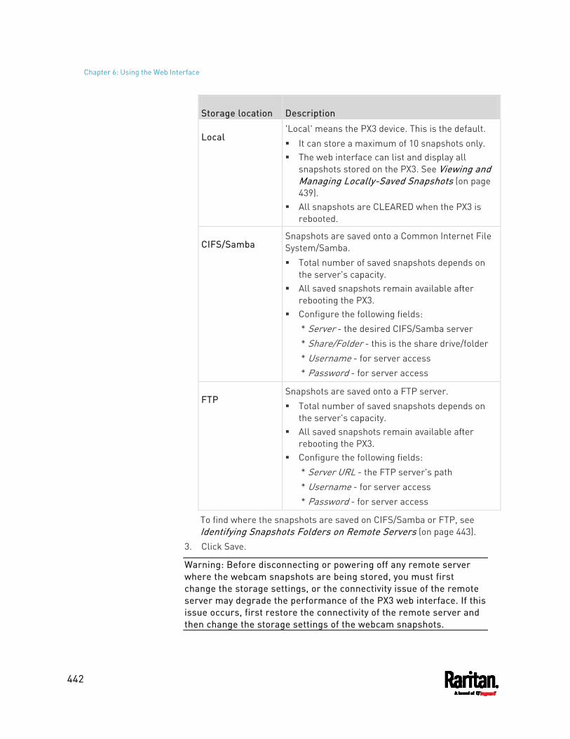
Chapter 6: Using the Web Interface
442
Storage location Description
Local 'Local' means the PX3 device. This is the default. It can store a maximum of 10 snapshots only. The web interface can list and display all
snapshots stored on the PX3. See Viewing and Managing Locally-Saved Snapshots (on page 439).
All snapshots are CLEARED when the PX3 is rebooted.
CIFS/Samba Snapshots are saved onto a Common Internet File System/Samba. Total number of saved snapshots depends on
the server's capacity. All saved snapshots remain available after
rebooting the PX3. Configure the following fields:
* Server - the desired CIFS/Samba server * Share/Folder - this is the share drive/folder * Username - for server access * Password - for server access
FTP Snapshots are saved onto a FTP server. Total number of saved snapshots depends on
the server's capacity. All saved snapshots remain available after
rebooting the PX3. Configure the following fields:
* Server URL - the FTP server's path * Username - for server access * Password - for server access
To find where the snapshots are saved on CIFS/Samba or FTP, see Identifying Snapshots Folders on Remote Servers (on page 443).
3. Click Save.
Warning: Before disconnecting or powering off any remote server where the webcam snapshots are being stored, you must first change the storage settings, or the connectivity issue of the remote server may degrade the performance of the PX3 web interface. If this issue occurs, first restore the connectivity of the remote server and then change the storage settings of the webcam snapshots.
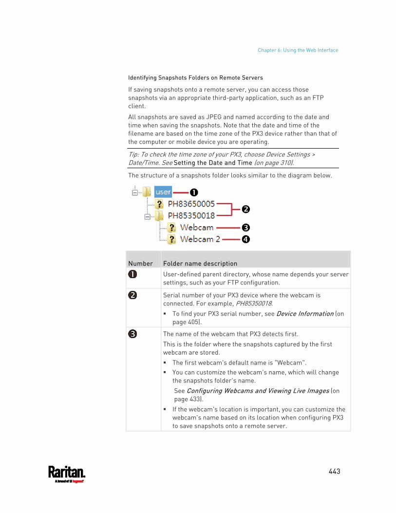
Chapter 6: Using the Web Interface
443
Identifying Snapshots Folders on Remote Servers
If saving snapshots onto a remote server, you can access those snapshots via an appropriate third-party application, such as an FTP client.
All snapshots are saved as JPEG and named according to the date and time when saving the snapshots. Note that the date and time of the filename are based on the time zone of the PX3 device rather than that of the computer or mobile device you are operating.
Tip: To check the time zone of your PX3, choose Device Settings > Date/Time. See Setting the Date and Time (on page 310).
The structure of a snapshots folder looks similar to the diagram below.
Number Folder name description
User-defined parent directory, whose name depends your server settings, such as your FTP configuration.
Serial number of your PX3 device where the webcam is connected. For example, PH85350018. To find your PX3 serial number, see Device Information (on
page 405).
The name of the webcam that PX3 detects first. This is the folder where the snapshots captured by the first webcam are stored. The first webcam's default name is "Webcam". You can customize the webcam's name, which will change
the snapshots folder's name. See Configuring Webcams and Viewing Live Images (on page 433).
If the webcam's location is important, you can customize the webcam's name based on its location when configuring PX3 to save snapshots onto a remote server.
Chapter 6: Using the Web Interface
444
Number Folder name description
The name of the webcam that PX3 detects later, if an additional webcam is connected. This is the folder where the snapshots captured by the second webcam are stored. The second webcam's default name is "Webcam 2". Changing this webcam's name also changes the second
snapshots folder's name. If the webcam's location is important, you can customize the
webcam's name based on its location when configuring PX3 to save snapshots onto a remote server.
Note: It is suggested to customize a webcam's name "prior to" saving snapshots on the remote server. In case you change the webcam's name after saving any snapshots, PX3 will create a new folder with the new webcam name while keeping the old folder with the old name.
SmartLock and Card Reader
Raritan's SmartLock kits provide several cabinet access control solutions.
If you have purchased a SmartLock kit with the door handle controller "DX2-DH2C2", both menu items "SmartLock" and "Card Readers" will appear in the menu after connecting and configuring properly DX2-DH2C2 and the door handles included in the kit.
Note: For more information on DX2-DH2C2, such as its hardware installation, refer to the SmartLock Quick Setup Guide accompanying the SmartLock kit or 'Environmental Sensors and Actuators Guide' (or its Online Help version) on the Raritan Support page (http://www.raritan.com/support/).
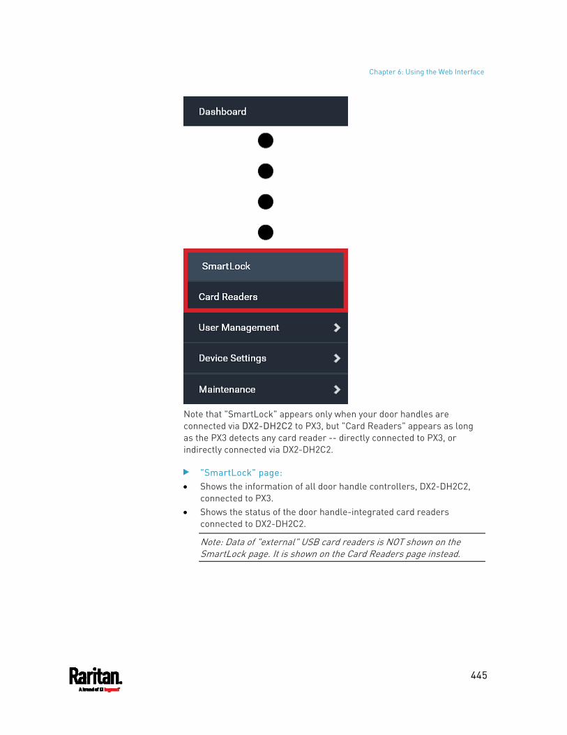
Chapter 6: Using the Web Interface
445
Note that "SmartLock" appears only when your door handles are connected via DX2-DH2C2 to PX3, but "Card Readers" appears as long as the PX3 detects any card reader -- directly connected to PX3, or indirectly connected via DX2-DH2C2.
"SmartLock" page: Shows the information of all door handle controllers, DX2-DH2C2,
connected to PX3. Shows the status of the door handle-integrated card readers
connected to DX2-DH2C2.
Note: Data of "external" USB card readers is NOT shown on the SmartLock page. It is shown on the Card Readers page instead.
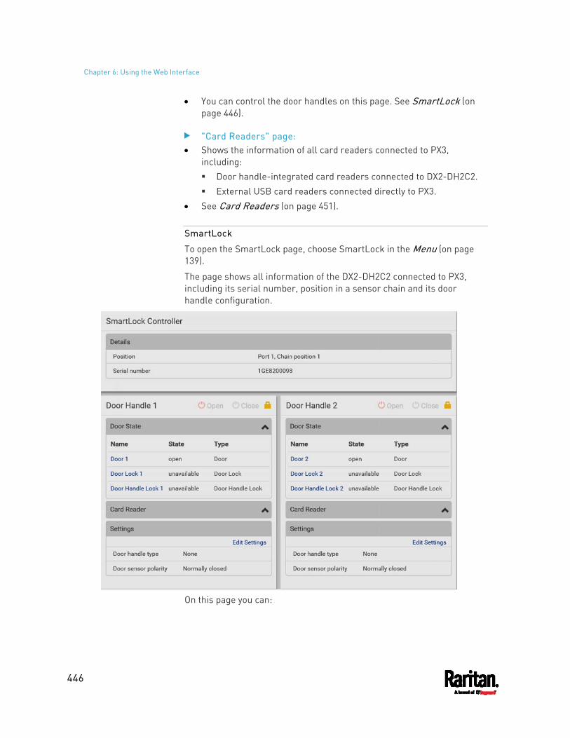
Chapter 6: Using the Web Interface
446
You can control the door handles on this page. See SmartLock (on page 446).
"Card Readers" page: Shows the information of all card readers connected to PX3,
including: Door handle-integrated card readers connected to DX2-DH2C2. External USB card readers connected directly to PX3.
See Card Readers (on page 451).
SmartLock
To open the SmartLock page, choose SmartLock in the Menu (on page 139).
The page shows all information of the DX2-DH2C2 connected to PX3, including its serial number, position in a sensor chain and its door handle configuration.
On this page you can:
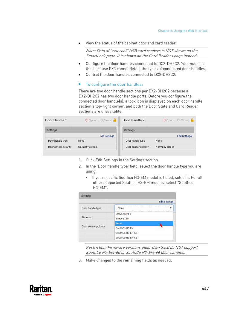
Chapter 6: Using the Web Interface
447
View the status of the cabinet door and card reader.
Note: Data of "external" USB card readers is NOT shown on the SmartLock page. It is shown on the Card Readers page instead.
Configure the door handles connected to DX2-DH2C2. You must set this because PX3 cannot detect the types of connected door handles.
Control the door handles connected to DX2-DH2C2.
To configure the door handles:
There are two door handle sections per DX2-DH2C2 because a DX2-DH2C2 has two door handle ports. Before you configure the connected door handle(s), a lock icon is displayed on each door handle section's top-right corner, and both the Door State and Card Reader sections are unavailable.
1. Click Edit Settings in the Settings section. 2. In the 'Door handle type' field, select the door handle type you are
using. If your specific Southco H3-EM model is listed, select it. For all
other supported Southco H3-EM models, select "Southco H3-EM".
Restriction: Firmware versions older than 3.5.0 do NOT support SouthCo H3-EM-60 or SouthCo H3-EM-66 door handles.
3. Make changes to the remaining fields as needed.
Chapter 6: Using the Web Interface
448
Section Description
Timeout Specify how long the door handle lock can remain
open after someone opens the door handle via a smart card or via remote control using the software. When the timeout expires, the door handle lock will be automatically closed. Default is 600 seconds (that is, 10 minutes).
Door sensor polarity
Determine which of the following status is considered normal for door locks. Normally closed: When the door lock is closed, it is
considered normal. This is the default. Normally open: When the door lock is opened, it is considered normal.
4. Click Save.
Door Handle Status and Control
After configuring the door handle type properly, two more sections are shown for the configured door handle -- Door State and Card Reader.
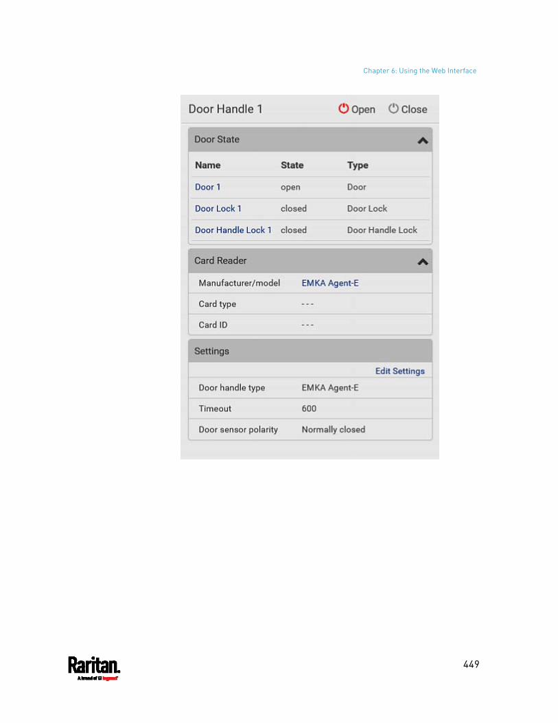
Chapter 6: Using the Web Interface
449
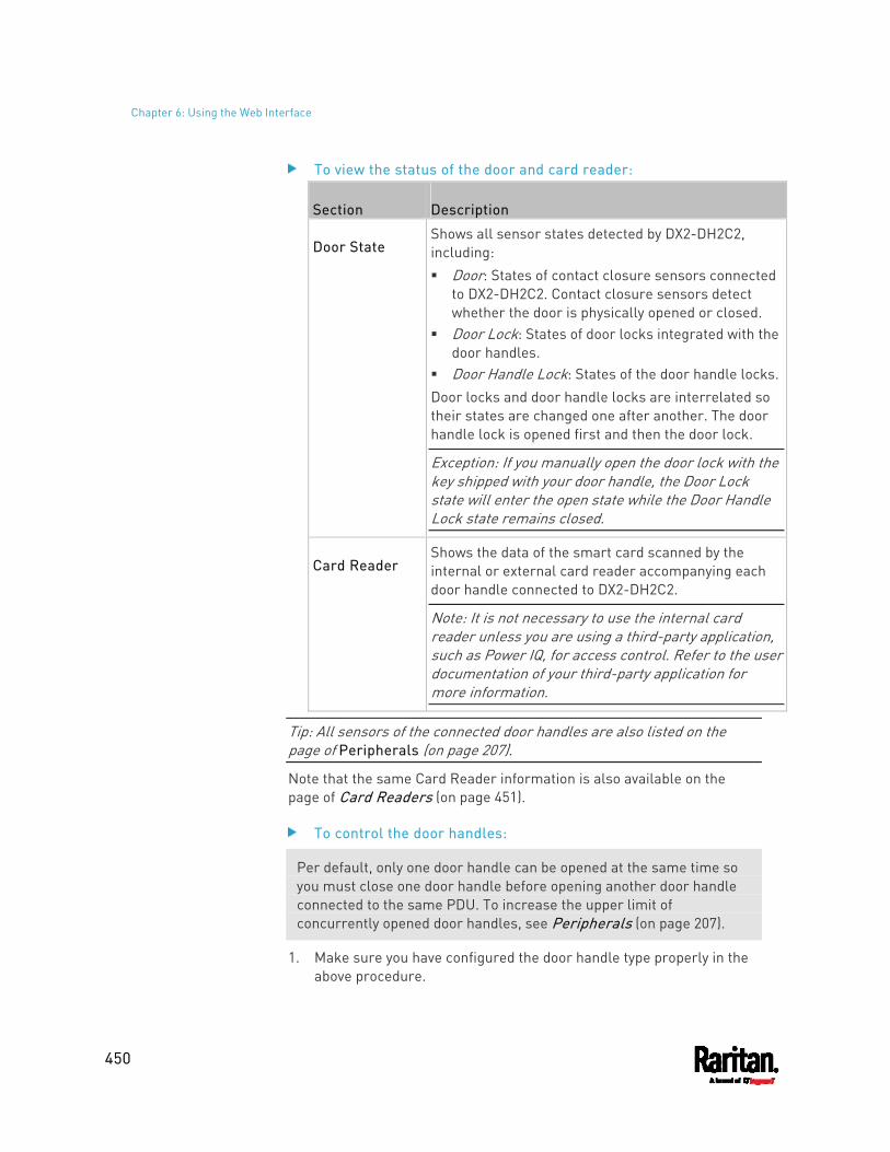
Chapter 6: Using the Web Interface
450
To view the status of the door and card reader:
Section Description
Door State Shows all sensor states detected by DX2-DH2C2, including: Door: States of contact closure sensors connected
to DX2-DH2C2. Contact closure sensors detect whether the door is physically opened or closed.
Door Lock: States of door locks integrated with the door handles.
Door Handle Lock: States of the door handle locks.Door locks and door handle locks are interrelated so their states are changed one after another. The door handle lock is opened first and then the door lock.
Exception: If you manually open the door lock with the key shipped with your door handle, the Door Lock state will enter the open state while the Door Handle Lock state remains closed.
Card Reader Shows the data of the smart card scanned by the internal or external card reader accompanying each door handle connected to DX2-DH2C2.
Note: It is not necessary to use the internal card reader unless you are using a third-party application, such as Power IQ, for access control. Refer to the user documentation of your third-party application for more information.
Tip: All sensors of the connected door handles are also listed on the page of Peripherals (on page 207).
Note that the same Card Reader information is also available on the page of Card Readers (on page 451).
To control the door handles:
Per default, only one door handle can be opened at the same time so you must close one door handle before opening another door handle connected to the same PDU. To increase the upper limit of concurrently opened door handles, see Peripherals (on page 207).
1. Make sure you have configured the door handle type properly in the above procedure.
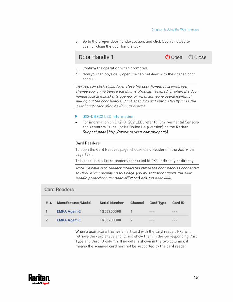
Chapter 6: Using the Web Interface
451
2. Go to the proper door handle section, and click Open or Close to open or close the door handle lock.
3. Confirm the operation when prompted. 4. Now you can physically open the cabinet door with the opened door
handle.
Tip: You can click Close to re-close the door handle lock when you change your mind before the door is physically opened, or when the door handle lock is mistakenly opened, or when someone opens it without pulling out the door handle. If not, then PX3 will automatically close the door handle lock after its timeout expires.
DX2-DH2C2 LED information: For information on DX2-DH2C2 LED, refer to 'Environmental Sensors
and Actuators Guide' (or its Online Help version) on the Raritan Support page (http://www.raritan.com/support/).
Card Readers
To open the Card Readers page, choose Card Readers in the Menu (on page 139).
This page lists all card readers connected to PX3, indirectly or directly.
Note: To have card readers integrated inside the door handles connected to DX2-DH2C2 display on this page, you must first configure the door handle properly on the page of SmartLock (on page 446).
When a user scans his/her smart card with the card reader, PX3 will retrieve the card's type and ID and show them in the corresponding Card Type and Card ID column. If no data is shown in the two columns, it means the scanned card may not be supported by the card reader.
Chapter 6: Using the Web Interface
452
Tip: You can use a third-party application, such as Power IQ, to retrieve the card's data from PX3 to perform security features like cabinet access control. Refer to that application's user documentation for more information.
Listed card readers can be one or both of the following types.
Door handle-integrated card readers: This type of card reader is integrated in the door handle, which is
either series below: Emka Agent E SouthCo H3-EM
Note: Not every SouthCo H3-EM door handle has a card reader integrated. For example, H3-EM-60-100 requires an external card reader.
It is indirectly connected to PX3 via DX2-DH2C2. The Channel column indicates which port (channel) on DX2-DH2C2 it
is connected to. Note that the serial number displayed for this card reader is the
serial number of DX2-DH2C2. Each DX2-PD2C2 can show two card readers because they have two ports for connecting two door handles with internal card readers.
External USB card readers: It is directly connected to PX3 via USB. The Channel column does not show any data.
453
This SNMP section helps you set up the PX3 for use with an SNMP manager. The PX3 can be configured to send traps or informs to an SNMP manager, as well as receive GET and SET commands in order to retrieve status and configure some basic settings.
In This Chapter
Enabling and Configuring SNMP............................................................. 453 Downloading SNMP MIB ......................................................................... 458 SNMP Gets and Sets................................................................................ 458
Enabling and Configuring SNMP
To communicate with an SNMP manager, you must enable SNMP protocols on the PX3. By default the "read-only" mode of SNMP v1/v2c is enabled.
The SNMP v3 protocol allows for encrypted communication. To take advantage of this, you must configure the users with the SNMP v3 access permission and set Authentication Pass Phrase and Privacy Pass Phrase, which act as shared secrets between SNMP and the PX3.
Important: You must download the SNMP MIB for your PX3 to use with your SNMP manager. See Downloading SNMP MIB (on page 458).
To enable SNMP v1/v2c and/or v3 protocols: 1. Choose Device Settings > Network Services > SNMP. 2. In the SNMP Agent section, enable SNMP v1/v2c or SNMP v3, and
configure related fields, such as the community strings. If SNMP v3 is enabled, you must determine which users shall
have the SNMP v3 access permission. See below. For details, see Configuring SNMP Settings (on page 280).
To configure users for SNMP v3 access: 1. Choose User Management > Users. 2. Create or modify users to enable their SNMP v3 access permission.
If authentication and privacy is enabled, configure the SNMP password(s) in the user settings.
For details, see Creating Users (on page 244).
Chapter 7 Using SNMP
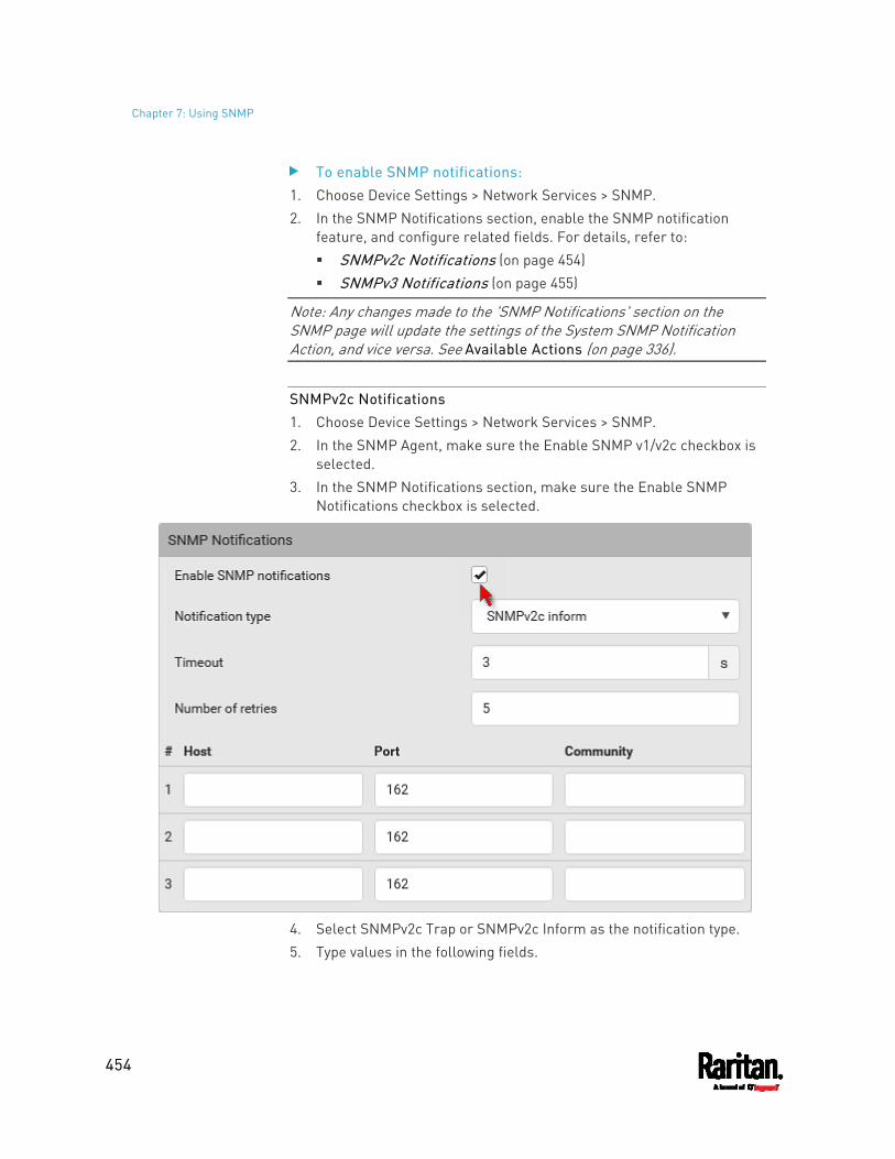
Chapter 7: Using SNMP
454
To enable SNMP notifications: 1. Choose Device Settings > Network Services > SNMP. 2. In the SNMP Notifications section, enable the SNMP notification
feature, and configure related fields. For details, refer to: SNMPv2c Notifications (on page 454) SNMPv3 Notifications (on page 455)
Note: Any changes made to the 'SNMP Notifications' section on the SNMP page will update the settings of the System SNMP Notification Action, and vice versa. See Available Actions (on page 336).
SNMPv2c Notifications 1. Choose Device Settings > Network Services > SNMP. 2. In the SNMP Agent, make sure the Enable SNMP v1/v2c checkbox is
selected. 3. In the SNMP Notifications section, make sure the Enable SNMP
Notifications checkbox is selected.
4. Select SNMPv2c Trap or SNMPv2c Inform as the notification type. 5. Type values in the following fields.
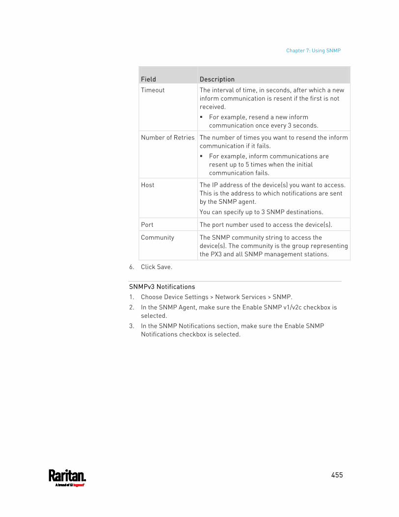
Chapter 7: Using SNMP
455
Field Description
Timeout The interval of time, in seconds, after which a new inform communication is resent if the first is not received. For example, resend a new inform
communication once every 3 seconds.
Number of Retries The number of times you want to resend the inform communication if it fails. For example, inform communications are
resent up to 5 times when the initial communication fails.
Host The IP address of the device(s) you want to access. This is the address to which notifications are sent by the SNMP agent. You can specify up to 3 SNMP destinations.
Port The port number used to access the device(s).
Community The SNMP community string to access the device(s). The community is the group representing the PX3 and all SNMP management stations.
6. Click Save.
SNMPv3 Notifications 1. Choose Device Settings > Network Services > SNMP. 2. In the SNMP Agent, make sure the Enable SNMP v1/v2c checkbox is
selected. 3. In the SNMP Notifications section, make sure the Enable SNMP
Notifications checkbox is selected.
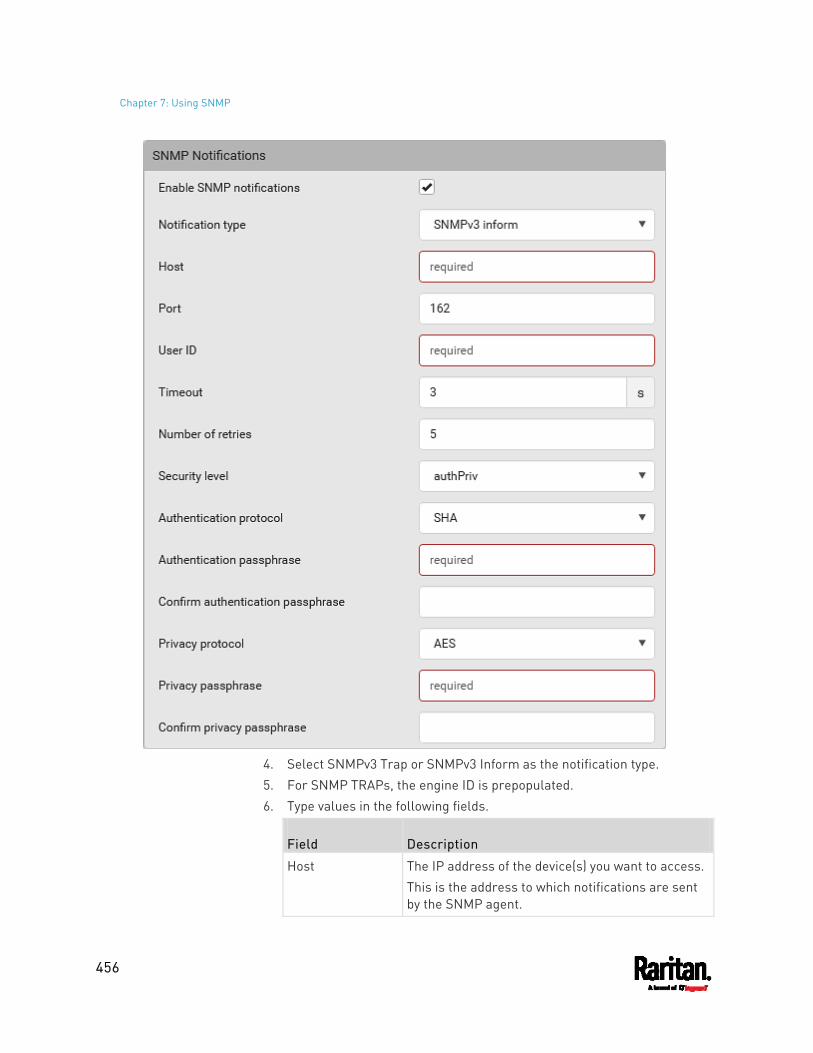
Chapter 7: Using SNMP
456
4. Select SNMPv3 Trap or SNMPv3 Inform as the notification type. 5. For SNMP TRAPs, the engine ID is prepopulated. 6. Type values in the following fields.
Field Description
Host The IP address of the device(s) you want to access. This is the address to which notifications are sent by the SNMP agent.
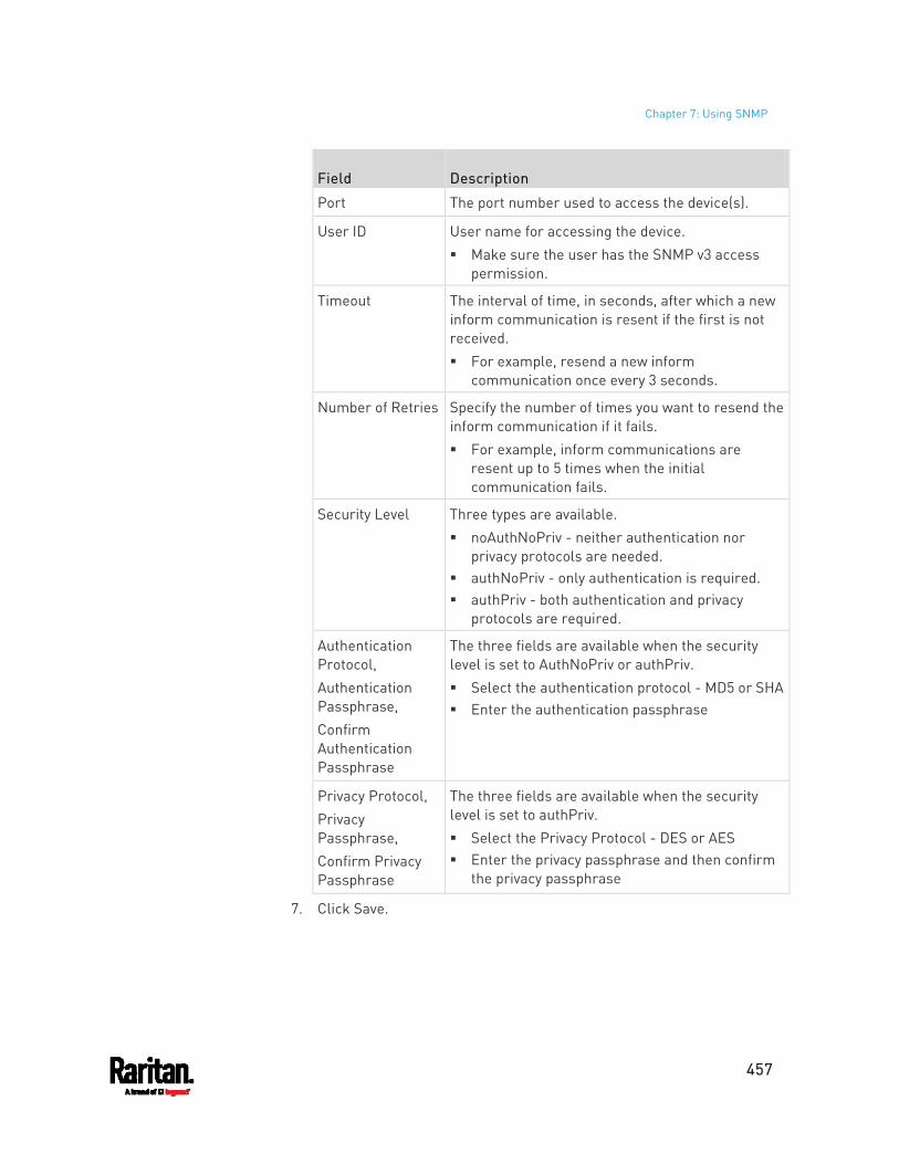
Chapter 7: Using SNMP
457
Field Description
Port The port number used to access the device(s).
User ID User name for accessing the device. Make sure the user has the SNMP v3 access
permission.
Timeout The interval of time, in seconds, after which a new inform communication is resent if the first is not received. For example, resend a new inform
communication once every 3 seconds.
Number of Retries Specify the number of times you want to resend the inform communication if it fails. For example, inform communications are
resent up to 5 times when the initial communication fails.
Security Level Three types are available. noAuthNoPriv - neither authentication nor
privacy protocols are needed. authNoPriv - only authentication is required. authPriv - both authentication and privacy
protocols are required.
Authentication Protocol, Authentication Passphrase, Confirm Authentication Passphrase
The three fields are available when the security level is set to AuthNoPriv or authPriv. Select the authentication protocol - MD5 or SHA Enter the authentication passphrase
Privacy Protocol, Privacy Passphrase, Confirm Privacy Passphrase
The three fields are available when the security level is set to authPriv. Select the Privacy Protocol - DES or AES Enter the privacy passphrase and then confirm
the privacy passphrase
7. Click Save.
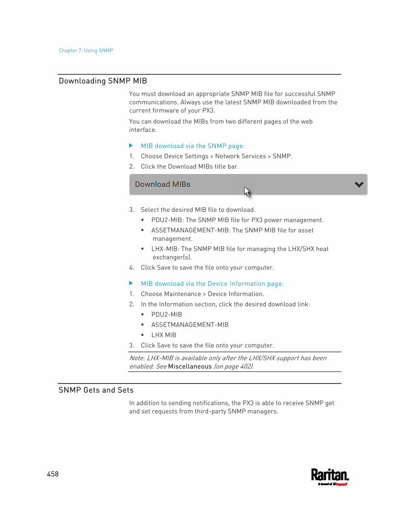
Chapter 7: Using SNMP
458
Downloading SNMP MIB
You must download an appropriate SNMP MIB file for successful SNMP communications. Always use the latest SNMP MIB downloaded from the current firmware of your PX3.
You can download the MIBs from two different pages of the web interface.
MIB download via the SNMP page: 1. Choose Device Settings > Network Services > SNMP. 2. Click the Download MIBs title bar.
3. Select the desired MIB file to download.
PDU2-MIB: The SNMP MIB file for PX3 power management. ASSETMANAGEMENT-MIB: The SNMP MIB file for asset
management. LHX-MIB: The SNMP MIB file for managing the LHX/SHX heat
exchanger(s). 4. Click Save to save the file onto your computer.
MIB download via the Device Information page: 1. Choose Maintenance > Device Information. 2. In the Information section, click the desired download link:
PDU2-MIB ASSETMANAGEMENT-MIB LHX MIB
3. Click Save to save the file onto your computer.
Note: LHX-MIB is available only after the LHX/SHX support has been enabled. See Miscellaneous (on page 402).
SNMP Gets and Sets
In addition to sending notifications, the PX3 is able to receive SNMP get and set requests from third-party SNMP managers.
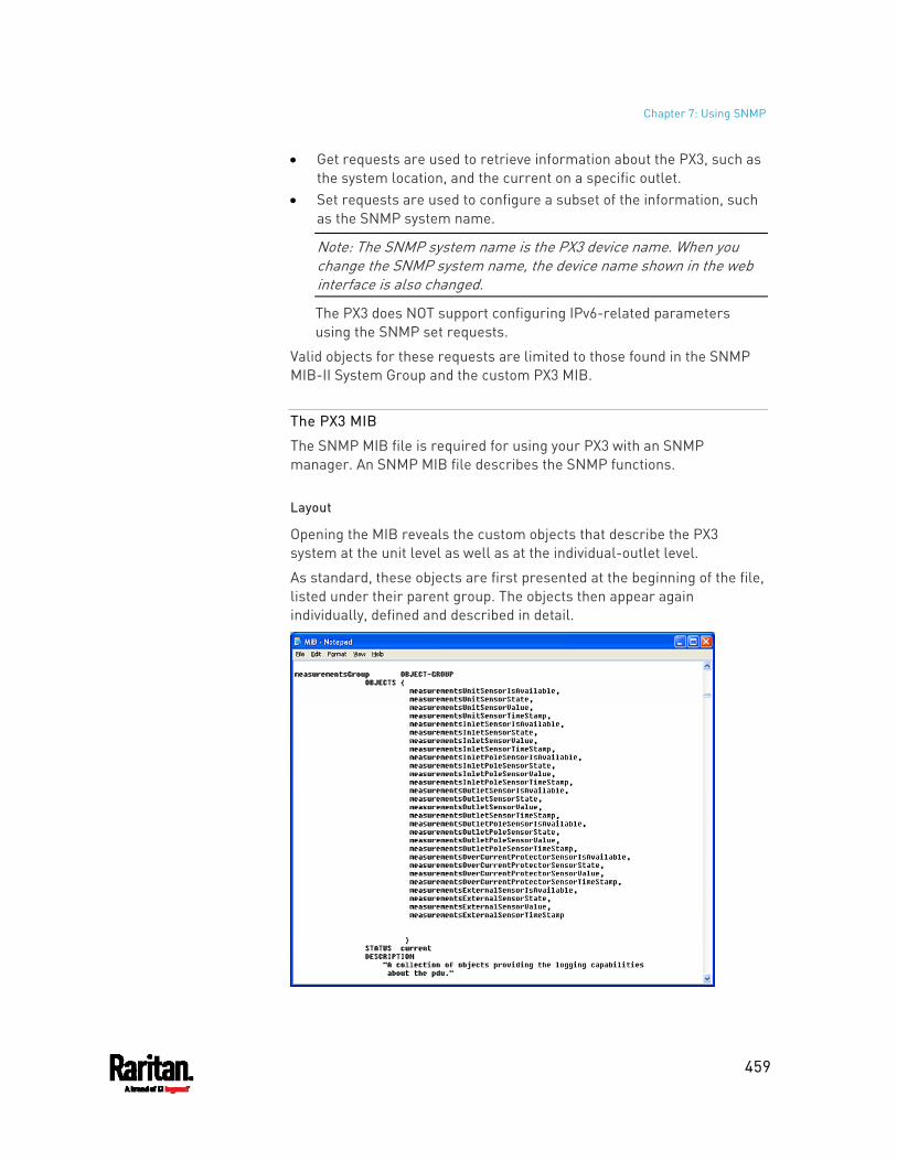
Chapter 7: Using SNMP
459
Get requests are used to retrieve information about the PX3, such as the system location, and the current on a specific outlet.
Set requests are used to configure a subset of the information, such as the SNMP system name.
Note: The SNMP system name is the PX3 device name. When you change the SNMP system name, the device name shown in the web interface is also changed.
The PX3 does NOT support configuring IPv6-related parameters using the SNMP set requests.
Valid objects for these requests are limited to those found in the SNMP MIB-II System Group and the custom PX3 MIB.
The PX3 MIB
The SNMP MIB file is required for using your PX3 with an SNMP manager. An SNMP MIB file describes the SNMP functions.
Layout
Opening the MIB reveals the custom objects that describe the PX3 system at the unit level as well as at the individual-outlet level.
As standard, these objects are first presented at the beginning of the file, listed under their parent group. The objects then appear again individually, defined and described in detail.
Chapter 7: Using SNMP
460
For example, the measurementsGroup group contains objects for sensor readings of PX3 as a whole. One object listed under this group, measurementsUnitSensorValue, is described later in the MIB as "The sensor value". pduRatedCurrent, part of the configGroup group, describes the PDU current rating.
SNMP Sets and Thresholds
Some objects can be configured from the SNMP manager using SNMP set commands. Objects that can be configured have a MAX-ACCESS level of "read-write" in the MIB.
These objects include threshold objects, which causes the PX3 to generate a warning and send an SNMP notification when certain parameters are exceeded. See Sensor Threshold Settings (on page 810) for a description of how thresholds work.
Note: When configuring the thresholds via SNMP set commands, ensure the value of upper critical threshold is higher than that of upper warning threshold.
Configuring NTP Server Settings
Using SNMP, you can change the following NTP server-related settings in the unitConfigurationTable:
Enable or disable synchronization of the device's date and time with NTP servers (synchronizeWithNTPServer)
Enable or disable the use of DHCP-assigned NTP servers if synchronization with NTP servers is enabled (useDHCPProvidedNTPServer)
Manually assign the primary NTP server if the use of DHCP-assigned NTP servers is disabled (firstNTPServerAddressType and firstNTPServerAddress)
Manually assign the secondary NTP server (optional) (secondNTPServerAddressType and secondNTPServerAddress)
Tip: To specify the time zone, use the CLI or web interface instead. For the CLI, see Setting the Time Zone (on page 535). For the web interface, see Setting the Date and Time (on page 310).
When using the SNMP SET command to specify or change NTP servers, it is required that both the NTP server's address type and address be set in the command line simultaneously.
For example, the SNMP command to change the primary NTP server's address from IPv4 (192.168.84.84) to host name looks similar to the following:
Chapter 7: Using SNMP
461
snmpset -v2c -c private 192.168.84.84 firstNTPServerAddressType = dns firstNTPServerAddress = "angu.pep.com"
Retrieving Energy Usage
You can discover how much energy an IT device consumes by retrieving the Active Energy for the outlet this IT device is plugged into. The Active Energy values are included in the outletSensorMeasurementsTable, along with other outlet sensor readings.
A Note about Enabling Thresholds
When enabling previously-disabled thresholds via SNMP, make sure you set a correct value for all thresholds that are supposed to be enabled prior to actually enabling them. Otherwise, you may get an error message.
462
This section explains how to use the command line interface (CLI) to administer the PX3.
Note that available CLI commands are model dependent.
CLI commands are case sensitive.
In This Chapter
About the Interface.................................................................................. 462 Logging in to CLI...................................................................................... 463 The ? Command for Showing Available Commands............................... 466 Querying Available Parameters for a Command.................................... 467 Showing Information ............................................................................... 467 Clearing Information ............................................................................... 499 Configuring the PX3 Device and Network............................................... 500 Load Shedding Configuration Commands .............................................. 627 Power Control Operations....................................................................... 628 Actuator Control Operations ................................................................... 631 Unblocking a User ................................................................................... 633 Resetting the PX3 .................................................................................... 633 Network Troubleshooting .......................................................................635 Retrieving Previous Commands.............................................................. 638 Automatically Completing a Command .................................................. 638 Logging out of CLI ................................................................................... 639
About the Interface
The PX3 provides a command line interface that enables data center administrators to perform some basic management tasks.
Using this interface, you can do the following:
Reset the PX3 Display the PX3 and network information, such as the device name,
firmware version, IP address, and so on Configure the PX3 and network settings Troubleshoot network problems
You can access the interface over a local connection using a terminal emulation program such as HyperTerminal, or via a Telnet or SSH client such as PuTTY.
Note: Telnet access is disabled by default because it communicates openly and is thus insecure. To enable Telnet, see Changing Telnet Settings (on page 285).
Chapter 8 Using the Command Line Interface
Chapter 8: Using the Command Line Interface
463
Logging in to CLI
Logging in via HyperTerminal over a local connection is a little different than logging in using SSH or Telnet.
If a security login agreement has been enabled, you must accept the agreement in order to complete the login. Users are authenticated first and the security banner is checked afterwards.
With HyperTerminal
You can use any terminal emulation programs for local access to the command line interface.
This section illustrates HyperTerminal, which is part of Windows operating systems prior to Windows Vista.
To log in using HyperTerminal: 1. Connect your computer to the product via a local (USB or RS-232)
connection. 2. Launch HyperTerminal on your computer and open a console
window. When the window first opens, it is blank. Make sure the COM port settings use this configuration: Bits per second = 115200 (115.2Kbps) Data bits = 8 Stop bits = 1 Parity = None Flow control = None
Tip: For a USB connection, you can determine the COM port by choosing Control Panel > System > Hardware > Device Manager, and locating the "Dominion PX2 Serial Console" under the Ports group.
3. In the communications program, press Enter to send a carriage return to the PX3. The Username prompt appears.
4. Type a name and press Enter. The name is case sensitive. Then you
are prompted to enter a password.
5. Type a password and press Enter. The password is case sensitive.
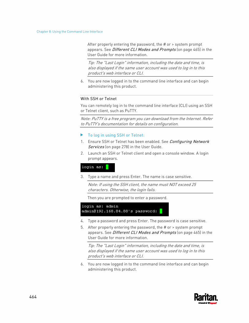
Chapter 8: Using the Command Line Interface
464
After properly entering the password, the # or > system prompt appears. See Different CLI Modes and Prompts (on page 465) in the User Guide for more information.
Tip: The "Last Login" information, including the date and time, is also displayed if the same user account was used to log in to this product's web interface or CLI.
6. You are now logged in to the command line interface and can begin administering this product.
With SSH or Telnet
You can remotely log in to the command line interface (CLI) using an SSH or Telnet client, such as PuTTY.
Note: PuTTY is a free program you can download from the Internet. Refer to PuTTY's documentation for details on configuration.
To log in using SSH or Telnet: 1. Ensure SSH or Telnet has been enabled. See Configuring Network
Services (on page 278) in the User Guide. 2. Launch an SSH or Telnet client and open a console window. A login
prompt appears.
3. Type a name and press Enter. The name is case sensitive.
Note: If using the SSH client, the name must NOT exceed 25 characters. Otherwise, the login fails.
Then you are prompted to enter a password.
4. Type a password and press Enter. The password is case sensitive. 5. After properly entering the password, the # or > system prompt
appears. See Different CLI Modes and Prompts (on page 465) in the User Guide for more information.
Tip: The "Last Login" information, including the date and time, is also displayed if the same user account was used to log in to this product's web interface or CLI.
6. You are now logged in to the command line interface and can begin administering this product.
Chapter 8: Using the Command Line Interface
465
With an Analog Modem
The PX3 supports remote access to the CLI via a connected analog modem. This feature is especially useful when the LAN access is not available.
To connect to the PX3 via the modem: 1. Make sure the PX3 has an analog modem connected. See
Connecting an Analog Modem (on page 76). 2. Make sure the computer you are using has an appropriate modem
connected. 3. Launch a terminal emulation program, and configure its baud rate
settings according to the baud rate set for the analog modem connected to the PX3. See Configuring the Serial Port (on page 394).
4. Type the following AT command to make a connection with the PX3. ATD<modem phone number>
5. The CLI login prompt appears after the connection is established successfully. Then type the user name and password to log in to the CLI.
To disconnect from the PX3: 1. Return to the modem's command mode using the escape code +++. 2. After the OK prompt appears, type the following AT command to
disconnect from the PX3. ATH
Different CLI Modes and Prompts
Depending on the login name you use and the mode you enter, the system prompt in the CLI varies.
Chapter 8: Using the Command Line Interface
466
User Mode: When you log in as a normal user, who may not have full permissions to configure the PX3, the > prompt appears.
Administrator Mode: When you log in as an administrator, who has full permissions to configure the PX3, the # prompt appears.
Configuration Mode: You can enter the configuration mode from the administrator or user mode. In this mode, the prompt changes to config:# or config:> and you can change PX3 device and network configurations. See Entering Configuration Mode (on page 500).
Diagnostic Mode: You can enter the diagnostic mode from the administrator or user mode. In this mode, the prompt changes to diag:# or diag:> and you can perform the network troubleshooting commands, such as the ping command. See Entering Diagnostic Mode (on page 635).
Closing a Local Connection
Close the window or terminal emulation program when you finish accessing the PX3 over the local connection.
When accessing or upgrading multiple PX3 devices, do not transfer the local connection cable from one device to another without closing the local connection window first.
The ? Command for Showing Available Commands
When you are not familiar with CLI commands, you can press the ? key at anytime for one of the following purposes.
Show a list of main CLI commands available in the current mode. Show a list of available commands or parameters for the command
you type. See Querying Available Parameters for a Command (on page 467).
In the administrator mode:
# ?
In the configuration mode:
config:# ?
In the diagnostic mode:
Chapter 8: Using the Command Line Interface
467
diag:# ?
Press Enter after pressing the ? command, and a list of main commands for the current mode is displayed.
Tip: To automatically complete a command after typing part of the full command, see Automatically Completing a Command (on page 638). To re-execute one of the previous commands, see Retrieving Previous Commands (on page 638).
Querying Available Parameters for a Command
f you are not sure what commands or parameters are available for a particular type of CLI command or its syntax, you can have the CLI show them by adding a space and the help command (?) or list command (ls) to the end of that command. A list of available parameters and their descriptions will be displayed.
The following shows a few query examples.
To query available parameters for the "show" command:
# show ?
To query available parameters for the "show user" command:
# show user ?
To query available role configuration parameters:
config:# role ?
To query available parameters for the "role create" command:
config:# role create ?
Tip: To automatically complete a command after typing part of the full command, see Automatically Completing a Command (on page 638). To re-execute one of the previous commands, see Retrieving Previous Commands (on page 638).
Chapter 8: Using the Command Line Interface
468
Showing Information
You can use the show commands to view current settings or the status of the PX3 device or part of it, such as the IP address, networking mode, firmware version, states or readings of internal or external sensors, user profiles, and so on.
Some "show" commands have two formats: one with the parameter "details" and the other without. The difference is that the command without the parameter "details" displays a shortened version of information while the other displays in-depth information.
After typing a "show" command, press Enter to execute it.
Note: Depending on your login name, the # prompt may be replaced by the > prompt. See Different CLI Modes and Prompts (on page 465).
Network Configuration
This command shows all network configuration and all network interfaces' information, such as the IP address, MAC address, the Ethernet interface's duplex mode, and the wireless interface's status/settings.
# show network
IP Configuration
This command shows the IP settings shared by all network interfaces, such as DNS and routes. Information shown will include both IPv4 and IPv6 configuration.
Tip: To show IPv4-only and IPv6-only configuration data, see IPv4-Only or IPv6-Only Configuration (on page 469).
# show network ip common
To show the IP settings of a specific network interface, use the following command.
# show network ip interface <ETH>
Variables:
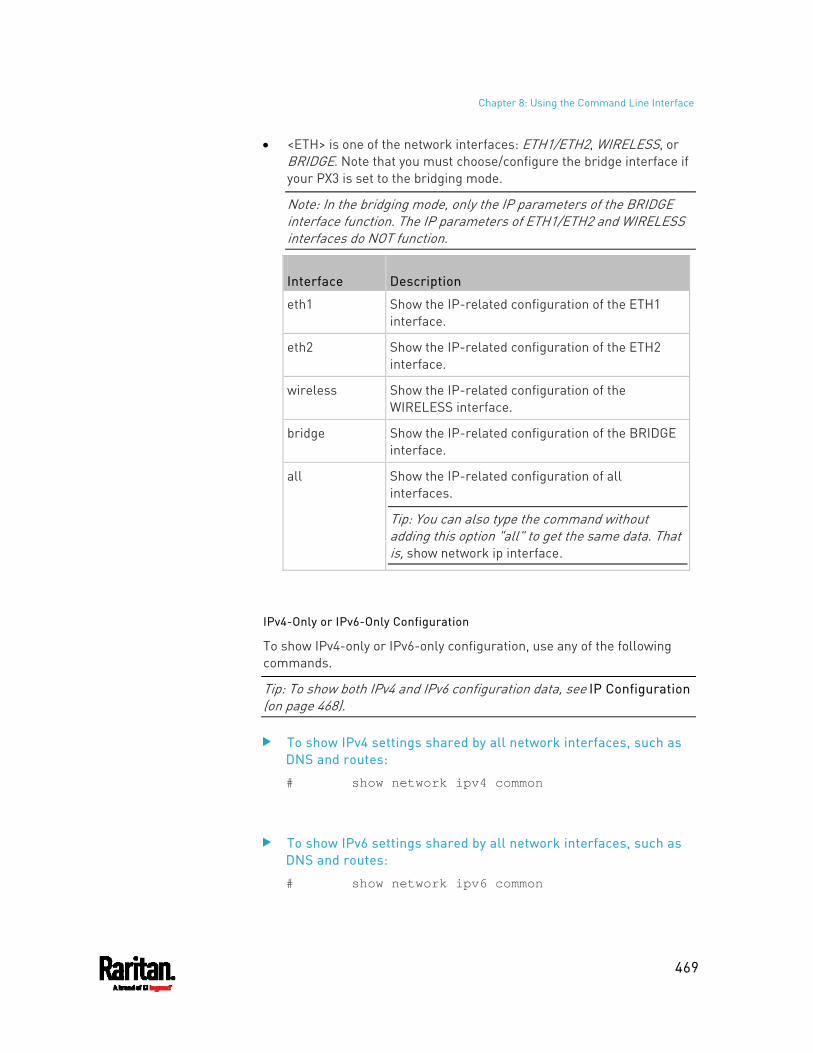
Chapter 8: Using the Command Line Interface
469
<ETH> is one of the network interfaces: ETH1/ETH2, WIRELESS, or BRIDGE. Note that you must choose/configure the bridge interface if your PX3 is set to the bridging mode.
Note: In the bridging mode, only the IP parameters of the BRIDGE interface function. The IP parameters of ETH1/ETH2 and WIRELESS interfaces do NOT function.
Interface Description
eth1 Show the IP-related configuration of the ETH1 interface.
eth2 Show the IP-related configuration of the ETH2 interface.
wireless Show the IP-related configuration of the WIRELESS interface.
bridge Show the IP-related configuration of the BRIDGE interface.
all Show the IP-related configuration of all interfaces.
Tip: You can also type the command without adding this option "all" to get the same data. That is, show network ip interface.
IPv4-Only or IPv6-Only Configuration
To show IPv4-only or IPv6-only configuration, use any of the following commands.
Tip: To show both IPv4 and IPv6 configuration data, see IP Configuration (on page 468).
To show IPv4 settings shared by all network interfaces, such as DNS and routes:
# show network ipv4 common
To show IPv6 settings shared by all network interfaces, such as DNS and routes:
# show network ipv6 common
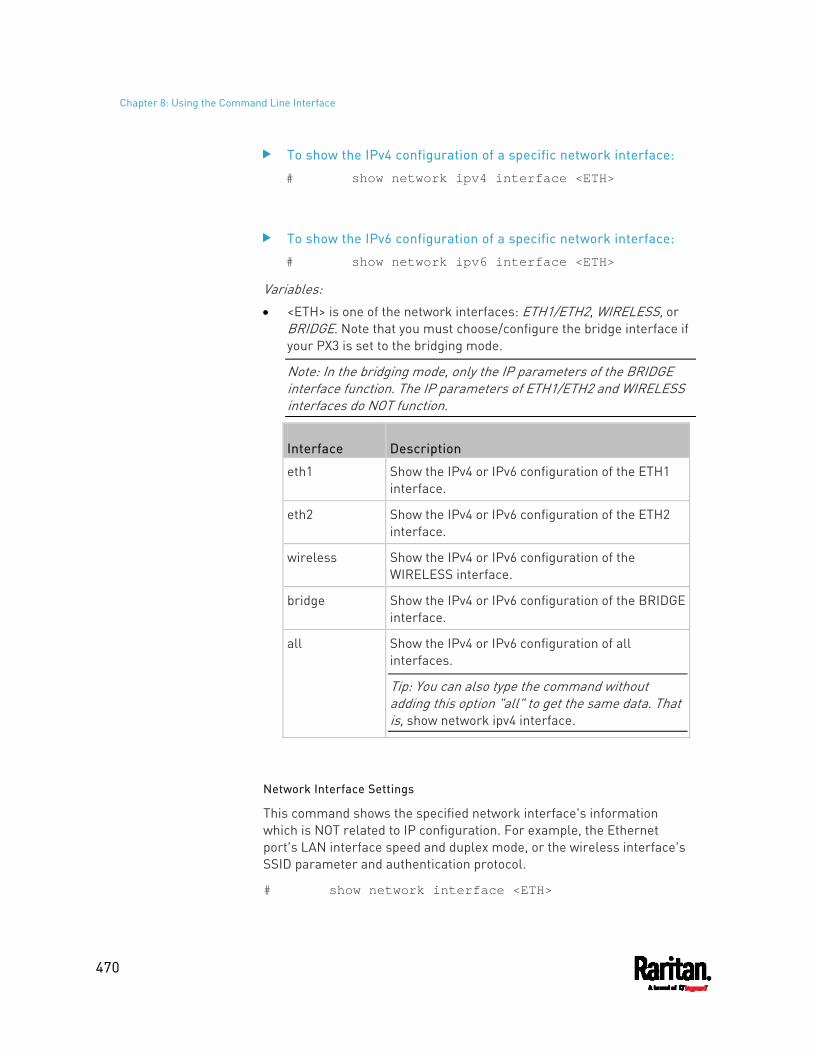
Chapter 8: Using the Command Line Interface
470
To show the IPv4 configuration of a specific network interface:
# show network ipv4 interface <ETH>
To show the IPv6 configuration of a specific network interface:
# show network ipv6 interface <ETH>
Variables: <ETH> is one of the network interfaces: ETH1/ETH2, WIRELESS, or
BRIDGE. Note that you must choose/configure the bridge interface if your PX3 is set to the bridging mode.
Note: In the bridging mode, only the IP parameters of the BRIDGE interface function. The IP parameters of ETH1/ETH2 and WIRELESS interfaces do NOT function.
Interface Description
eth1 Show the IPv4 or IPv6 configuration of the ETH1 interface.
eth2 Show the IPv4 or IPv6 configuration of the ETH2 interface.
wireless Show the IPv4 or IPv6 configuration of the WIRELESS interface.
bridge Show the IPv4 or IPv6 configuration of the BRIDGE interface.
all Show the IPv4 or IPv6 configuration of all interfaces.
Tip: You can also type the command without adding this option "all" to get the same data. That is, show network ipv4 interface.
Network Interface Settings
This command shows the specified network interface's information which is NOT related to IP configuration. For example, the Ethernet port's LAN interface speed and duplex mode, or the wireless interface's SSID parameter and authentication protocol.
# show network interface <ETH>
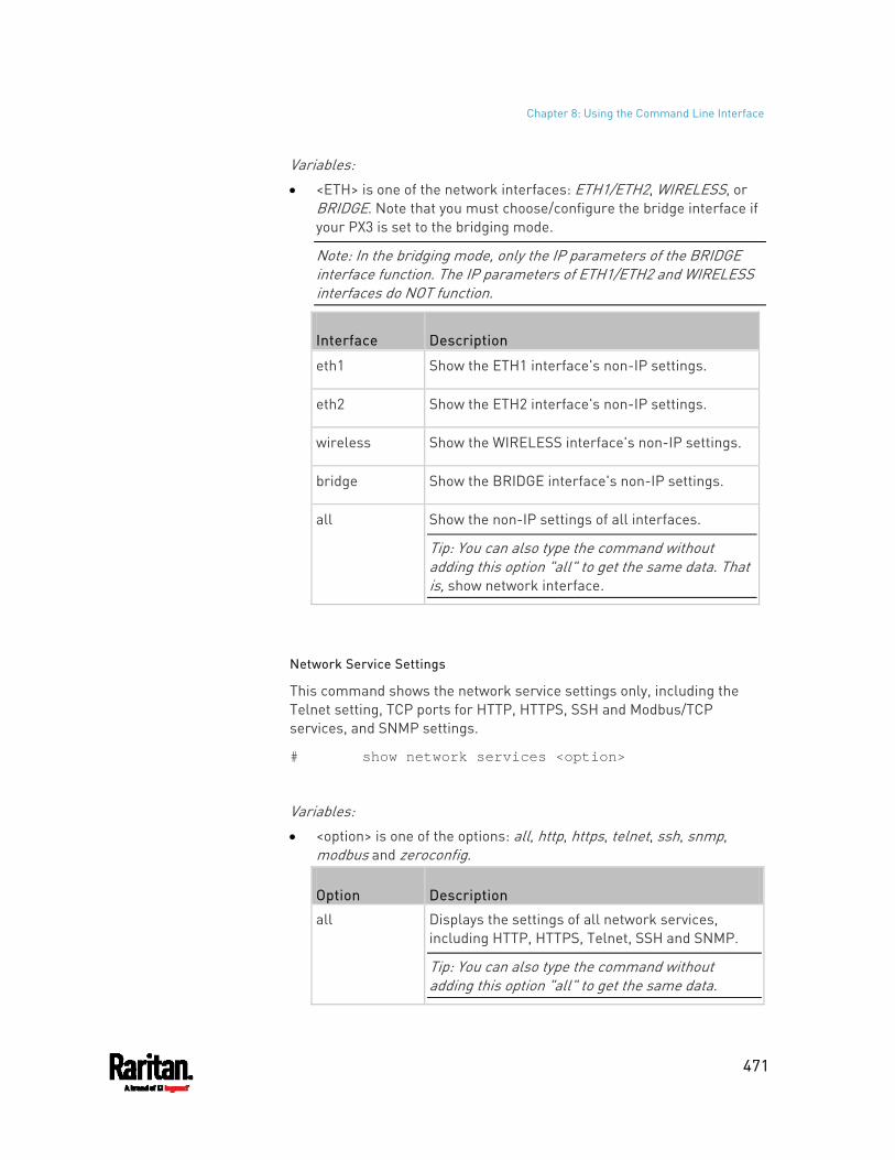
Chapter 8: Using the Command Line Interface
471
Variables: <ETH> is one of the network interfaces: ETH1/ETH2, WIRELESS, or
BRIDGE. Note that you must choose/configure the bridge interface if your PX3 is set to the bridging mode.
Note: In the bridging mode, only the IP parameters of the BRIDGE interface function. The IP parameters of ETH1/ETH2 and WIRELESS interfaces do NOT function.
Interface Description
eth1 Show the ETH1 interface's non-IP settings.
eth2 Show the ETH2 interface's non-IP settings.
wireless Show the WIRELESS interface's non-IP settings.
bridge Show the BRIDGE interface's non-IP settings.
all Show the non-IP settings of all interfaces.
Tip: You can also type the command without adding this option "all" to get the same data. That is, show network interface.
Network Service Settings
This command shows the network service settings only, including the Telnet setting, TCP ports for HTTP, HTTPS, SSH and Modbus/TCP services, and SNMP settings.
# show network services <option>
Variables: <option> is one of the options: all, http, https, telnet, ssh, snmp,
modbus and zeroconfig.
Option Description
all Displays the settings of all network services, including HTTP, HTTPS, Telnet, SSH and SNMP.
Tip: You can also type the command without adding this option "all" to get the same data.
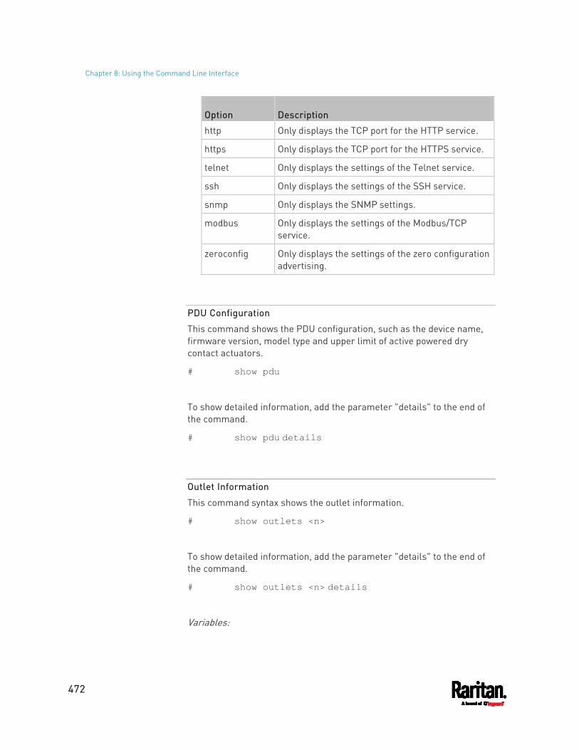
Chapter 8: Using the Command Line Interface
472
Option Description
http Only displays the TCP port for the HTTP service.
https Only displays the TCP port for the HTTPS service.
telnet Only displays the settings of the Telnet service.
ssh Only displays the settings of the SSH service.
snmp Only displays the SNMP settings.
modbus Only displays the settings of the Modbus/TCP service.
zeroconfig Only displays the settings of the zero configuration advertising.
PDU Configuration
This command shows the PDU configuration, such as the device name, firmware version, model type and upper limit of active powered dry contact actuators.
# show pdu
To show detailed information, add the parameter "details" to the end of the command.
# show pdu details
Outlet Information
This command syntax shows the outlet information.
# show outlets <n>
To show detailed information, add the parameter "details" to the end of the command.
# show outlets <n> details
Variables:
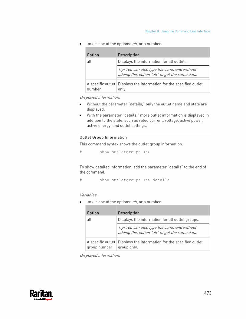
Chapter 8: Using the Command Line Interface
473
<n> is one of the options: all, or a number.
Option Description
all Displays the information for all outlets.
Tip: You can also type the command without adding this option "all" to get the same data.
A specific outlet number
Displays the information for the specified outlet only.
Displayed information: Without the parameter "details," only the outlet name and state are
displayed. With the parameter "details," more outlet information is displayed in
addition to the state, such as rated current, voltage, active power, active energy, and outlet settings.
Outlet Group Information
This command syntax shows the outlet group information.
# show outletgroups <n>
To show detailed information, add the parameter "details" to the end of the command.
# show outletgroups <n> details
Variables: <n> is one of the options: all, or a number.
Option Description
all Displays the information for all outlet groups.
Tip: You can also type the command without adding this option "all" to get the same data.
A specific outlet group number
Displays the information for the specified outlet group only.
Displayed information:
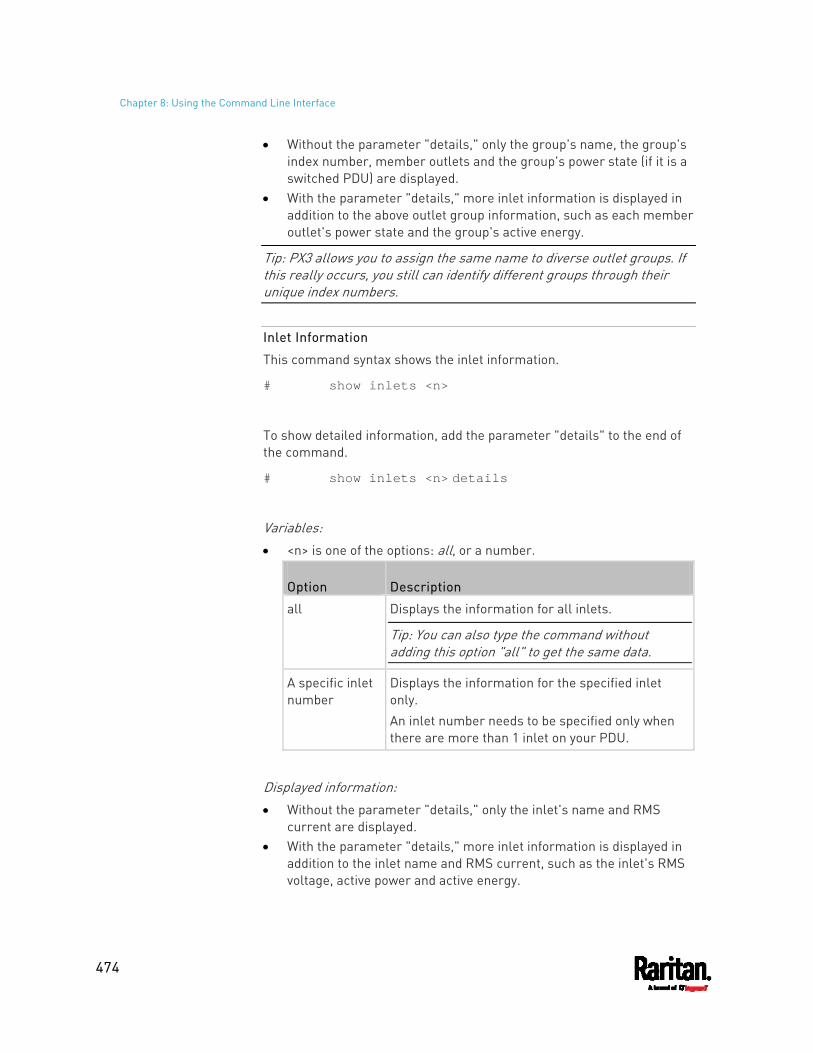
Chapter 8: Using the Command Line Interface
474
Without the parameter "details," only the group's name, the group's index number, member outlets and the group's power state (if it is a switched PDU) are displayed.
With the parameter "details," more inlet information is displayed in addition to the above outlet group information, such as each member outlet's power state and the group's active energy.
Tip: PX3 allows you to assign the same name to diverse outlet groups. If this really occurs, you still can identify different groups through their unique index numbers.
Inlet Information
This command syntax shows the inlet information.
# show inlets <n>
To show detailed information, add the parameter "details" to the end of the command.
# show inlets <n> details
Variables: <n> is one of the options: all, or a number.
Option Description
all Displays the information for all inlets.
Tip: You can also type the command without adding this option "all" to get the same data.
A specific inlet number
Displays the information for the specified inlet only. An inlet number needs to be specified only when there are more than 1 inlet on your PDU.
Displayed information: Without the parameter "details," only the inlet's name and RMS
current are displayed. With the parameter "details," more inlet information is displayed in
addition to the inlet name and RMS current, such as the inlet's RMS voltage, active power and active energy.
Chapter 8: Using the Command Line Interface
475
Overcurrent Protector Information
This command is only available for models with overcurrent protectors for protecting outlets.
This command syntax shows the overcurrent protector information, such as a circuit breaker or a fuse.
# show ocp <n>
To show detailed information, add the parameter "details" to the end of the command.
# show ocp <n> details
Variables: <n> is one of the options: all, or a number.
Option Description
all Displays the information for all overcurrent protectors.
Tip: You can also type the command without adding this option "all" to get the same data.
A specific overcurrent protector number
Displays the information for the specified overcurrent protector only.
Displayed information: Without the parameter "details," only the overcurrent protector
status and name are displayed. With the parameter "details," more overcurrent protector
information is displayed in addition to status, such as the rating and RMS current value.
For Raritan's outlet-metered models that support "outlet peak current" sensors, information indicating which outlet MAY cause the OCP-tripped event is available with this command. See Possible OCP-Tripped Root Cause (on page 206).
Date and Time Settings
This command shows the current date and time settings on the PX3.
Chapter 8: Using the Command Line Interface
476
# show time
To show detailed information, add the parameter "details" to the end of the command.
# show time details
Default Measurement Units
This command shows the default measurement units applied to the PX3 web and CLI interfaces across all users, especially those users authenticated through remote authentication servers.
# show user defaultPreferences
Note: If a user has set his/her own preferred measurement units or the administrator has changed any user's preferred units, the web and CLI interfaces show the preferred measurement units for that user instead of the default ones after that user logs in to the PX3. See Existing User Profiles (on page 490) for the preferred measurement units for a specific user.
Environmental Sensor Information
This command syntax shows the environmental sensor's information.
# show externalsensors <n>
To show detailed information, add the parameter "details" to the end of the command.
# show externalsensors <n> details
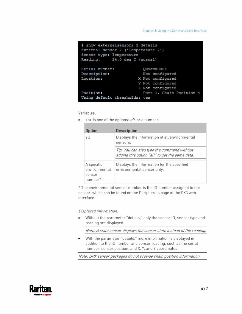
Chapter 8: Using the Command Line Interface
477
Variables:
<n> is one of the options: all, or a number.
Option Description
all Displays the information of all environmental sensors.
Tip: You can also type the command without adding this option "all" to get the same data.
A specific environmental sensor number*
Displays the information for the specified environmental sensor only.
* The environmental sensor number is the ID number assigned to the sensor, which can be found on the Peripherals page of the PX3 web interface.
Displayed information: Without the parameter "details," only the sensor ID, sensor type and
reading are displayed.
Note: A state sensor displays the sensor state instead of the reading.
With the parameter "details," more information is displayed in addition to the ID number and sensor reading, such as the serial number, sensor position, and X, Y, and Z coordinates.
Note: DPX sensor packages do not provide chain position information.
Chapter 8: Using the Command Line Interface
478
Environmental Sensor Package Information
Different from the "show externalsensors" commands, which show the reading, status and configuration of an individual environmental sensor, the following command shows the information of all connected environmental sensor packages, each of which may contain more than one sensor or actuator.
# show peripheralDevicePackages
Information similar to the following is displayed. An environmental sensor package is a peripheral device package.
Peripheral Device Package 1 Serial Number: AEI7A00022 Package Type: DPX-T1H1 Position: Port 1 Package State: operational Firmware Version: Not available
Peripheral Device Package 2 Serial Number: AEI7A00021 Package Type: DPX-T3H1 Position: Port 1 Package State: operational Firmware Version: Not available
Actuator Information
This command syntax shows an actuator's information.
# show actuators <n>
To show detailed information, add the parameter "details" to the end of the command.
# show actuators <n> details
Variables:
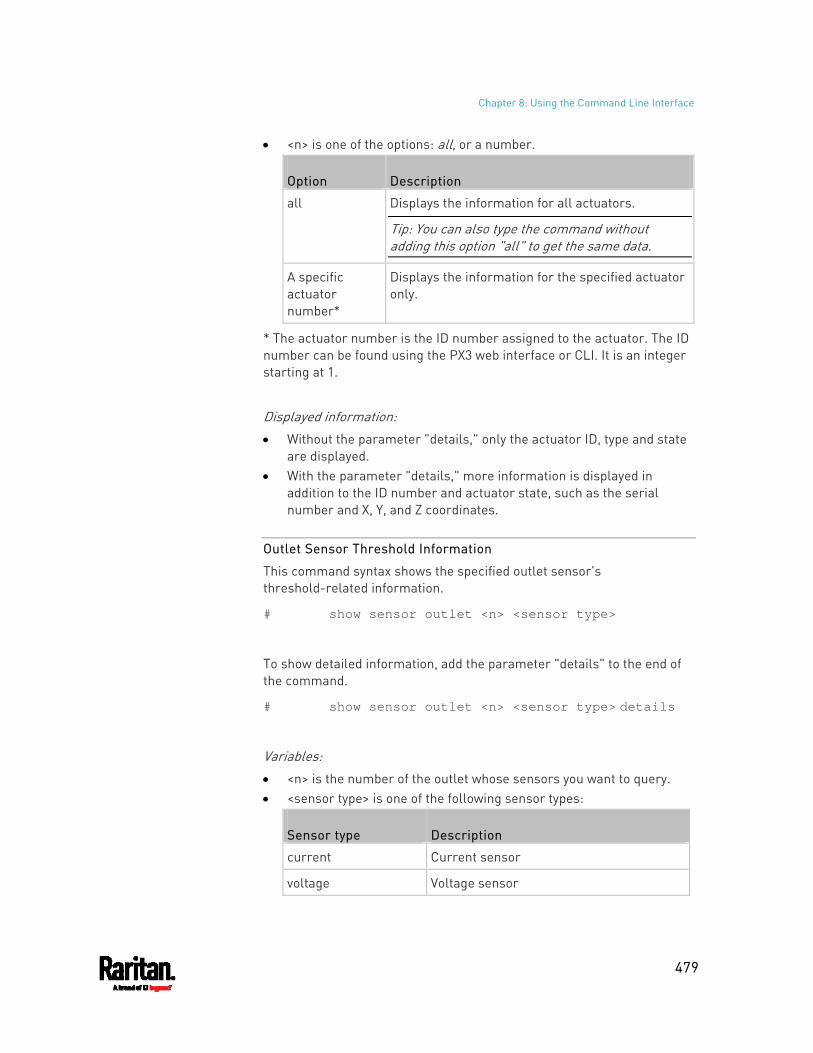
Chapter 8: Using the Command Line Interface
479
<n> is one of the options: all, or a number.
Option Description
all Displays the information for all actuators.
Tip: You can also type the command without adding this option "all" to get the same data.
A specific actuator number*
Displays the information for the specified actuator only.
* The actuator number is the ID number assigned to the actuator. The ID number can be found using the PX3 web interface or CLI. It is an integer starting at 1.
Displayed information: Without the parameter "details," only the actuator ID, type and state
are displayed. With the parameter "details," more information is displayed in
addition to the ID number and actuator state, such as the serial number and X, Y, and Z coordinates.
Outlet Sensor Threshold Information
This command syntax shows the specified outlet sensor's threshold-related information.
# show sensor outlet <n> <sensor type>
To show detailed information, add the parameter "details" to the end of the command.
# show sensor outlet <n> <sensor type> details
Variables: <n> is the number of the outlet whose sensors you want to query. <sensor type> is one of the following sensor types:
Sensor type Description
current Current sensor
voltage Voltage sensor
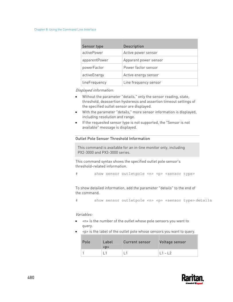
Chapter 8: Using the Command Line Interface
480
Sensor type Description
activePower Active power sensor
apparentPower Apparent power sensor
powerFactor Power factor sensor
activeEnergy Active energy sensor
lineFrequency Line frequency sensor
Displayed information: Without the parameter "details," only the sensor reading, state,
threshold, deassertion hysteresis and assertion timeout settings of the specified outlet sensor are displayed.
With the parameter "details," more sensor information is displayed, including resolution and range.
If the requested sensor type is not supported, the "Sensor is not available" message is displayed.
Outlet Pole Sensor Threshold Information
This command is available for an in-line monitor only, including PX2-3000 and PX3-3000 series.
This command syntax shows the specified outlet pole sensor's threshold-related information.
# show sensor outletpole <n> <p> <sensor type>
To show detailed information, add the parameter "details" to the end of the command.
# show sensor outletpole <n> <p> <sensor type> details
Variables: <n> is the number of the outlet whose pole sensors you want to
query. <p> is the label of the outlet pole whose sensors you want to query.
Pole Label <p>
Current sensor Voltage sensor
1 L1 L1 L1 - L2
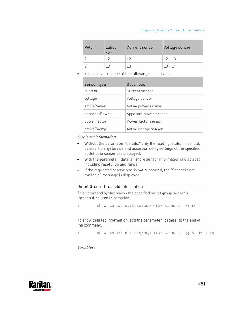
Chapter 8: Using the Command Line Interface
481
Pole Label <p>
Current sensor Voltage sensor
2 L2 L2 L2 - L3
3 L3 L3 L3 - L1
<sensor type> is one of the following sensor types:
Sensor type Description
current Current sensor
voltage Voltage sensor
activePower Active power sensor
apparentPower Apparent power sensor
powerFactor Power factor sensor
activeEnergy Active energy sensor
Displayed information: Without the parameter "details," only the reading, state, threshold,
deassertion hysteresis and assertion delay settings of the specified outlet pole sensor are displayed.
With the parameter "details," more sensor information is displayed, including resolution and range.
If the requested sensor type is not supported, the "Sensor is not available" message is displayed.
Outlet Group Threshold Information
This command syntax shows the specified outlet group sensor's threshold-related information.
# show sensor outletgroup <ID> <sensor type>
To show detailed information, add the parameter "details" to the end of the command.
# show sensor outletgroup <ID> <sensor type> details
Variables:
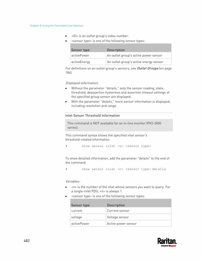
Chapter 8: Using the Command Line Interface
482
<ID> is an outlet group's index number. <sensor type> is one of the following sensor types:
Sensor type Description
activePower An outlet group's active power sensor
activeEnergy An outlet group's active energy sensor
For definitions on an outlet group's sensors, see Outlet Groups (on page 186). Displayed information: Without the parameter "details," only the sensor reading, state,
threshold, deassertion hysteresis and assertion timeout settings of the specified group sensor are displayed.
With the parameter "details," more sensor information is displayed, including resolution and range.
Inlet Sensor Threshold Information
This command is NOT available for an in-line monitor (PX3-3000 series).
This command syntax shows the specified inlet sensor's threshold-related information.
# show sensor inlet <n> <sensor type>
To show detailed information, add the parameter "details" to the end of the command.
# show sensor inlet <n> <sensor type> details
Variables: <n> is the number of the inlet whose sensors you want to query. For
a single-inlet PDU, <n> is always 1. <sensor type> is one of the following sensor types:
Sensor type Description
current Current sensor
voltage Voltage sensor
activePower Active power sensor
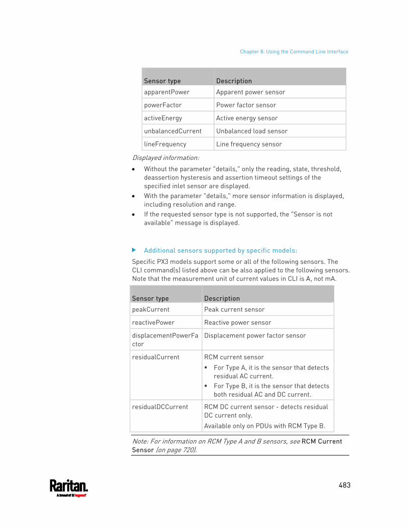
Chapter 8: Using the Command Line Interface
483
Sensor type Description
apparentPower Apparent power sensor
powerFactor Power factor sensor
activeEnergy Active energy sensor
unbalancedCurrent Unbalanced load sensor
lineFrequency Line frequency sensor
Displayed information: Without the parameter "details," only the reading, state, threshold,
deassertion hysteresis and assertion timeout settings of the specified inlet sensor are displayed.
With the parameter "details," more sensor information is displayed, including resolution and range.
If the requested sensor type is not supported, the "Sensor is not available" message is displayed.
Additional sensors supported by specific models:
Specific PX3 models support some or all of the following sensors. The CLI command(s) listed above can be also applied to the following sensors. Note that the measurement unit of current values in CLI is A, not mA.
Sensor type Description
peakCurrent Peak current sensor
reactivePower Reactive power sensor
displacementPowerFactor
Displacement power factor sensor
residualCurrent RCM current sensor For Type A, it is the sensor that detects
residual AC current. For Type B, it is the sensor that detects
both residual AC and DC current.
residualDCCurrent RCM DC current sensor - detects residual DC current only. Available only on PDUs with RCM Type B.
Note: For information on RCM Type A and B sensors, see RCM Current Sensor (on page 720).
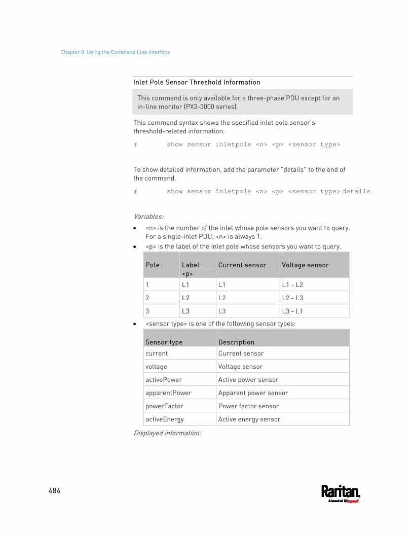
Chapter 8: Using the Command Line Interface
484
Inlet Pole Sensor Threshold Information
This command is only available for a three-phase PDU except for an in-line monitor (PX3-3000 series).
This command syntax shows the specified inlet pole sensor's threshold-related information.
# show sensor inletpole <n> <p> <sensor type>
To show detailed information, add the parameter "details" to the end of the command.
# show sensor inletpole <n> <p> <sensor type> details
Variables: <n> is the number of the inlet whose pole sensors you want to query.
For a single-inlet PDU, <n> is always 1. <p> is the label of the inlet pole whose sensors you want to query.
Pole Label <p>
Current sensor Voltage sensor
1 L1 L1 L1 - L2
2 L2 L2 L2 - L3
3 L3 L3 L3 - L1
<sensor type> is one of the following sensor types:
Sensor type Description
current Current sensor
voltage Voltage sensor
activePower Active power sensor
apparentPower Apparent power sensor
powerFactor Power factor sensor
activeEnergy Active energy sensor
Displayed information:
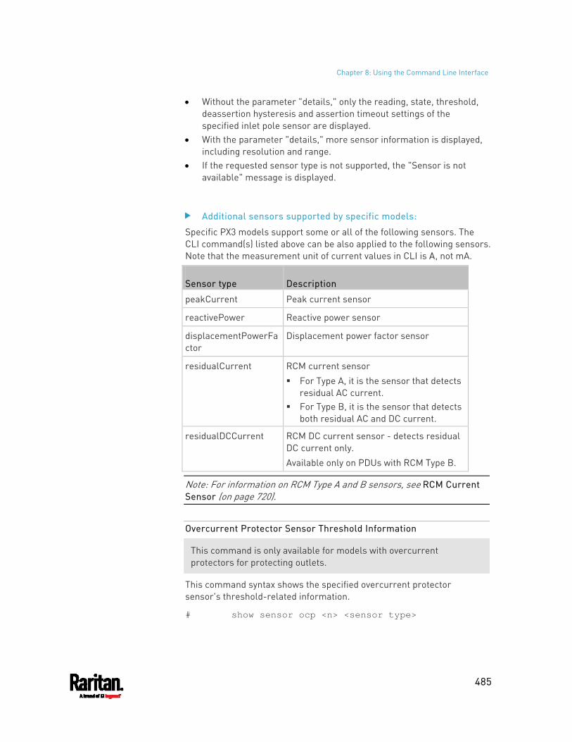
Chapter 8: Using the Command Line Interface
485
Without the parameter "details," only the reading, state, threshold, deassertion hysteresis and assertion timeout settings of the specified inlet pole sensor are displayed.
With the parameter "details," more sensor information is displayed, including resolution and range.
If the requested sensor type is not supported, the "Sensor is not available" message is displayed.
Additional sensors supported by specific models:
Specific PX3 models support some or all of the following sensors. The CLI command(s) listed above can be also applied to the following sensors. Note that the measurement unit of current values in CLI is A, not mA.
Sensor type Description
peakCurrent Peak current sensor
reactivePower Reactive power sensor
displacementPowerFactor
Displacement power factor sensor
residualCurrent RCM current sensor For Type A, it is the sensor that detects
residual AC current. For Type B, it is the sensor that detects
both residual AC and DC current.
residualDCCurrent RCM DC current sensor - detects residual DC current only. Available only on PDUs with RCM Type B.
Note: For information on RCM Type A and B sensors, see RCM Current Sensor (on page 720).
Overcurrent Protector Sensor Threshold Information
This command is only available for models with overcurrent protectors for protecting outlets.
This command syntax shows the specified overcurrent protector sensor's threshold-related information.
# show sensor ocp <n> <sensor type>
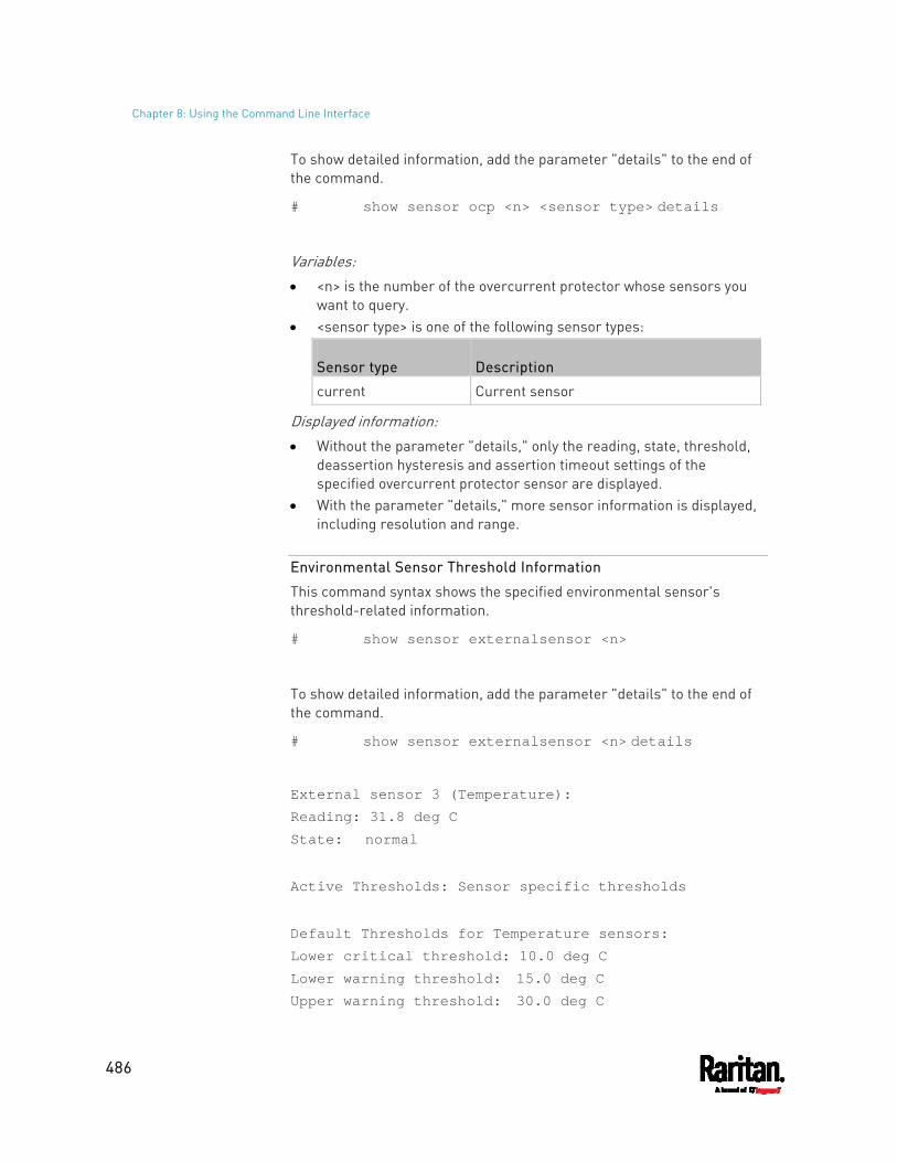
Chapter 8: Using the Command Line Interface
486
To show detailed information, add the parameter "details" to the end of the command.
# show sensor ocp <n> <sensor type> details
Variables: <n> is the number of the overcurrent protector whose sensors you
want to query. <sensor type> is one of the following sensor types:
Sensor type Description
current Current sensor
Displayed information: Without the parameter "details," only the reading, state, threshold,
deassertion hysteresis and assertion timeout settings of the specified overcurrent protector sensor are displayed.
With the parameter "details," more sensor information is displayed, including resolution and range.
Environmental Sensor Threshold Information
This command syntax shows the specified environmental sensor's threshold-related information.
# show sensor externalsensor <n>
To show detailed information, add the parameter "details" to the end of the command.
# show sensor externalsensor <n> details
External sensor 3 (Temperature): Reading: 31.8 deg C State: normal
Active Thresholds: Sensor specific thresholds
Default Thresholds for Temperature sensors: Lower critical threshold: 10.0 deg C Lower warning threshold: 15.0 deg C Upper warning threshold: 30.0 deg C
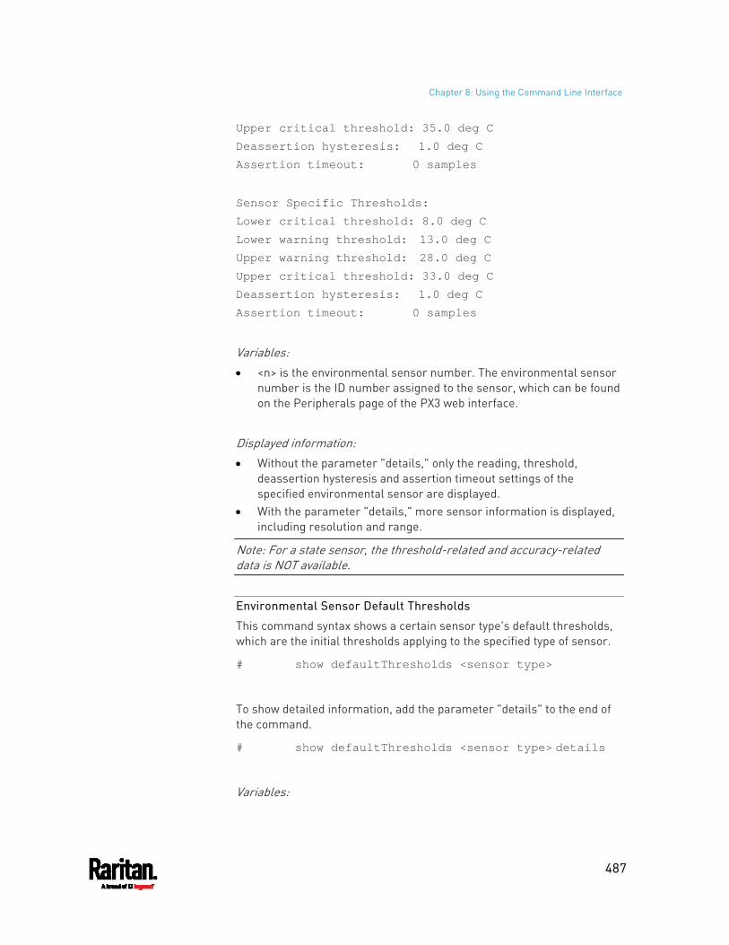
Chapter 8: Using the Command Line Interface
487
Upper critical threshold: 35.0 deg C Deassertion hysteresis: 1.0 deg C Assertion timeout: 0 samples
Sensor Specific Thresholds: Lower critical threshold: 8.0 deg C Lower warning threshold: 13.0 deg C Upper warning threshold: 28.0 deg C Upper critical threshold: 33.0 deg C Deassertion hysteresis: 1.0 deg C Assertion timeout: 0 samples
Variables: <n> is the environmental sensor number. The environmental sensor
number is the ID number assigned to the sensor, which can be found on the Peripherals page of the PX3 web interface.
Displayed information: Without the parameter "details," only the reading, threshold,
deassertion hysteresis and assertion timeout settings of the specified environmental sensor are displayed.
With the parameter "details," more sensor information is displayed, including resolution and range.
Note: For a state sensor, the threshold-related and accuracy-related data is NOT available.
Environmental Sensor Default Thresholds
This command syntax shows a certain sensor type's default thresholds, which are the initial thresholds applying to the specified type of sensor.
# show defaultThresholds <sensor type>
To show detailed information, add the parameter "details" to the end of the command.
# show defaultThresholds <sensor type> details
Variables:
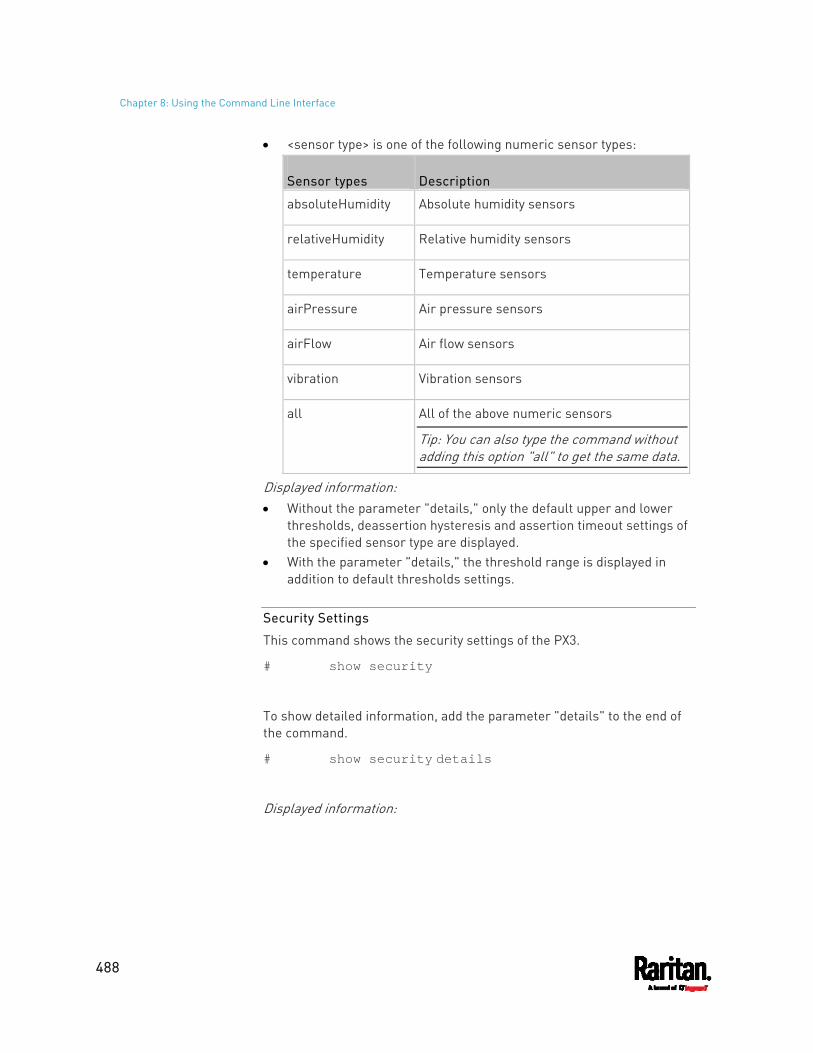
Chapter 8: Using the Command Line Interface
488
<sensor type> is one of the following numeric sensor types:
Sensor types Description
absoluteHumidity Absolute humidity sensors
relativeHumidity Relative humidity sensors
temperature Temperature sensors
airPressure Air pressure sensors
airFlow Air flow sensors
vibration Vibration sensors
all All of the above numeric sensors
Tip: You can also type the command without adding this option "all" to get the same data.
Displayed information: Without the parameter "details," only the default upper and lower
thresholds, deassertion hysteresis and assertion timeout settings of the specified sensor type are displayed.
With the parameter "details," the threshold range is displayed in addition to default thresholds settings.
Security Settings
This command shows the security settings of the PX3.
# show security
To show detailed information, add the parameter "details" to the end of the command.
# show security details
Displayed information:
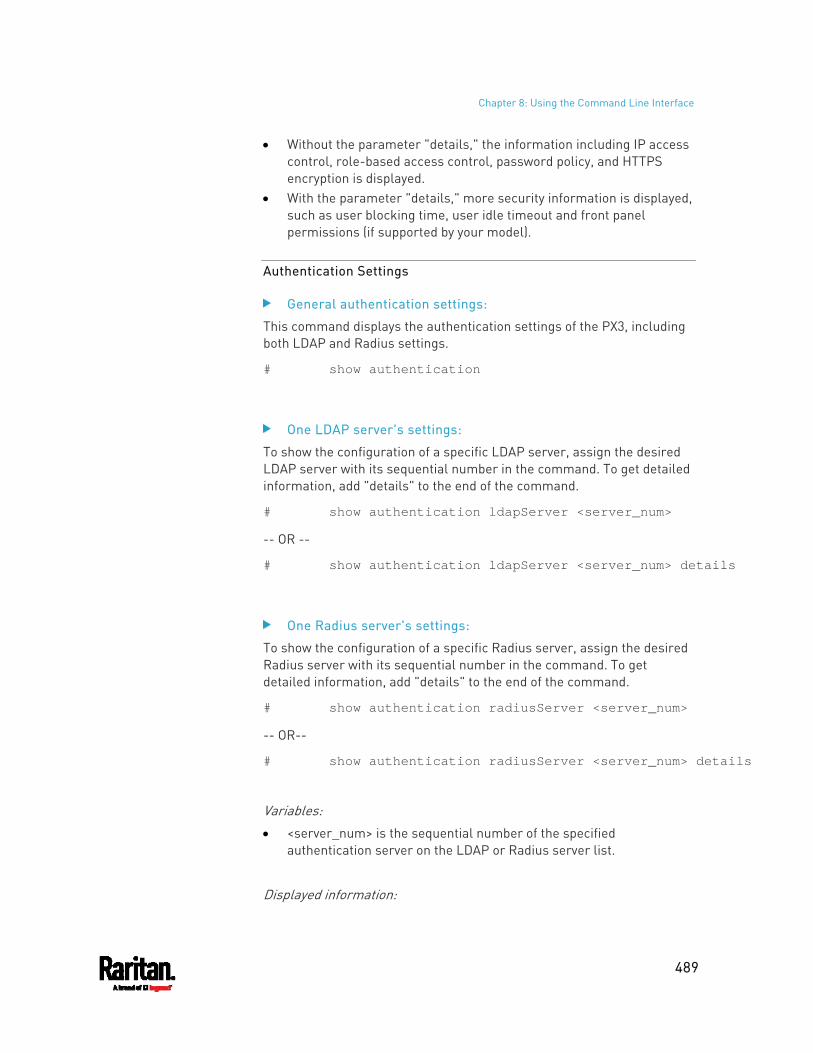
Chapter 8: Using the Command Line Interface
489
Without the parameter "details," the information including IP access control, role-based access control, password policy, and HTTPS encryption is displayed.
With the parameter "details," more security information is displayed, such as user blocking time, user idle timeout and front panel permissions (if supported by your model).
Authentication Settings
General authentication settings:
This command displays the authentication settings of the PX3, including both LDAP and Radius settings.
# show authentication
One LDAP server's settings:
To show the configuration of a specific LDAP server, assign the desired LDAP server with its sequential number in the command. To get detailed information, add "details" to the end of the command.
# show authentication ldapServer <server_num>
-- OR --
# show authentication ldapServer <server_num> details
One Radius server's settings:
To show the configuration of a specific Radius server, assign the desired Radius server with its sequential number in the command. To get detailed information, add "details" to the end of the command.
# show authentication radiusServer <server_num>
-- OR--
# show authentication radiusServer <server_num> details
Variables: <server_num> is the sequential number of the specified
authentication server on the LDAP or Radius server list.
Displayed information:
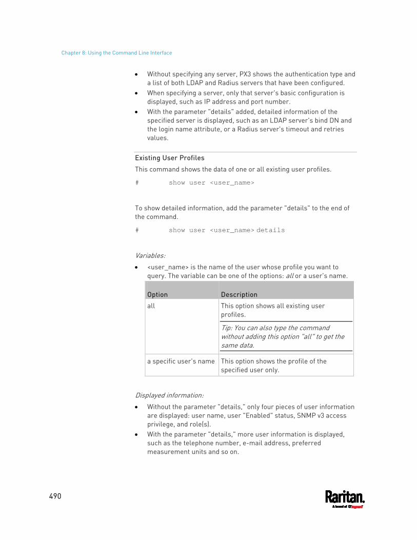
Chapter 8: Using the Command Line Interface
490
Without specifying any server, PX3 shows the authentication type and a list of both LDAP and Radius servers that have been configured.
When specifying a server, only that server's basic configuration is displayed, such as IP address and port number.
With the parameter "details" added, detailed information of the specified server is displayed, such as an LDAP server's bind DN and the login name attribute, or a Radius server's timeout and retries values.
Existing User Profiles
This command shows the data of one or all existing user profiles.
# show user <user_name>
To show detailed information, add the parameter "details" to the end of the command.
# show user <user_name> details
Variables: <user_name> is the name of the user whose profile you want to
query. The variable can be one of the options: all or a user's name.
Option Description
all This option shows all existing user profiles.
Tip: You can also type the command without adding this option "all" to get the same data.
a specific user's name This option shows the profile of the specified user only.
Displayed information: Without the parameter "details," only four pieces of user information
are displayed: user name, user "Enabled" status, SNMP v3 access privilege, and role(s).
With the parameter "details," more user information is displayed, such as the telephone number, e-mail address, preferred measurement units and so on.
Chapter 8: Using the Command Line Interface
491
Existing Roles
This command shows the data of one or all existing roles.
# show roles <role_name>
Variables: <role_name> is the name of the role whose permissions you want to
query. The variable can be one of the following options:
Option Description
all This option shows all existing roles.
Tip: You can also type the command without adding this option "all" to get the same data.
a specific role's name This option shows the data of the specified role only.
Displayed information: Role settings are displayed, including the role description and
privileges.
Load Shedding Settings
This section applies to outlet-switching capable models only.
This command shows the load shedding settings.
# show loadshedding
Displayed information: The load shedding state is displayed along with non-critical outlets.
Note: The load shedding mode is associated with critical and non-critical outlets. To specify critical and non-critical outlets through CLI, see Specifying Non-Critical Outlets (on page 505).
Serial Port Settings
This command shows the baud rate setting of the serial port labeled CONSOLE / MODEM on the PX3.
Chapter 8: Using the Command Line Interface
492
# show serial
EnergyWise Settings
This command shows the PX3 device's current configuration for Cisco® EnergyWise.
# show energywise
Asset Strip Settings
This command shows the asset strip settings, such as the total number of rack units (tag ports), asset strip state, numbering mode, orientation, available tags and LED color settings.
# show assetStrip <n>
Variables: <n> is one of the options: all, or a number.
Option Description
all Displays all asset strip information.
Tip: You can also type the command without adding this option "all" to get the same data.
A specific asset strip number
Displays the settings of the asset strip connected to the specified FEATURE port number. For the PX3 device with only one FEATURE port, the valid number is always 1.
Rack Unit Settings of an Asset Strip
A rack unit refers to a tag port on the asset strips. This command shows the settings of a specific rack unit or all rack units on an asset strip, such as a rack unit's LED color and LED mode.
# show rackUnit <n> <rack_unit>
Variables:
Chapter 8: Using the Command Line Interface
493
<n> is the number of the FEATURE port where the selected asset strip is physically connected. For the PX3 device with only one FEATURE port, the number is always 1.
<rack_unit> is one of the options: all or a specific rack unit's index number.
Option Description
all Displays the settings of all rack units on the specified asset strip.
Tip: You can also type the command without adding this option "all" to get the same data.
A specific number
Displays the settings of the specified rack unit on the specified asset strip. Use the index number to specify the rack unit. The index number is available on the asset strip or the Asset Strip page of the web interface.
Blade Extension Strip Settings
This command shows the information of a blade extension strip, including the total number of tag ports, and if available, the ID (barcode) number of any connected tag.
# show bladeSlot <n> <rack_unit> <slot>
Variables: <n> is the number of the FEATURE port where the selected asset
strip is physically connected. For the PX3 device with only one FEATURE port, the number is always 1.
<rack_unit> is the index number of the desired rack unit (tag port) on the selected asset strip. The index number is available on the asset strip or the Asset Strip page of the web interface.
<slot> is one of the options: all or a specific number of a tag port on the blade extension strip.
Option Description
all Displays the information of all tag ports on the specified blade extension strip connected to a particular rack unit.
Tip: You can also type the command without adding this option "all" to get the same data.
Chapter 8: Using the Command Line Interface
494
Option Description
A specific number
Displays the information of the specified tag port on the blade extension strip connected to a particular rack unit. The number of each tag port on the blade extension strip is available on the Asset Strip page.
Event Log
The command used to show the event log begins with show eventlog. You can add either the limit or class parameters or both to show specific events.
Show the last 30 entries:
# show eventlog
Show a specific number of last entries in the event log:
# show eventlog limit <n>
Show a specific type of events only:
# show eventlog class <event_type>
Show a specific number of last entries associated with a specific type of events only:
# show eventlog limit <n> class <event_type>
Variables: <n> is one of the options: all or a number.
Option Description
all Displays all entries in the event log.
An integer number
Displays the specified number of last entries in the event log. The number ranges between 1 to 10,000.
<event_type> is one of the following event types.
Event type Description
all All events.
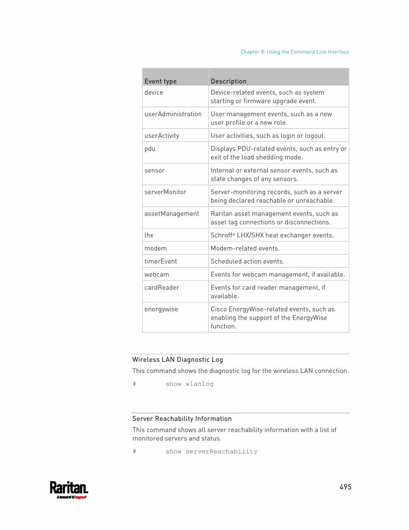
Chapter 8: Using the Command Line Interface
495
Event type Description
device Device-related events, such as system starting or firmware upgrade event.
userAdministration User management events, such as a new user profile or a new role.
userActivity User activities, such as login or logout.
pdu Displays PDU-related events, such as entry or exit of the load shedding mode.
sensor Internal or external sensor events, such as state changes of any sensors.
serverMonitor Server-monitoring records, such as a server being declared reachable or unreachable.
assetManagement Raritan asset management events, such as asset tag connections or disconnections.
lhx Schroff® LHX/SHX heat exchanger events.
modem Modem-related events.
timerEvent Scheduled action events.
webcam Events for webcam management, if available.
cardReader Events for card reader management, if available.
energywise Cisco EnergyWise-related events, such as enabling the support of the EnergyWise function.
Wireless LAN Diagnostic Log
This command shows the diagnostic log for the wireless LAN connection.
# show wlanlog
Server Reachability Information
This command shows all server reachability information with a list of monitored servers and status.
# show serverReachability
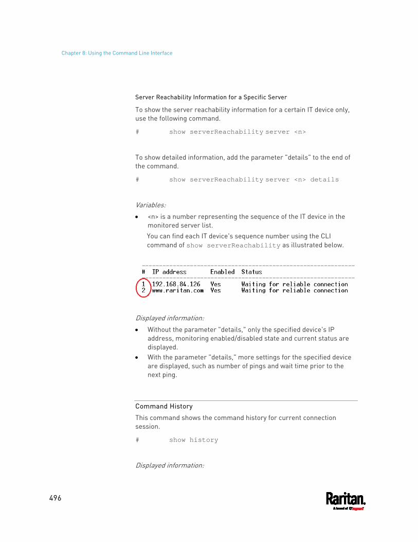
Chapter 8: Using the Command Line Interface
496
Server Reachability Information for a Specific Server
To show the server reachability information for a certain IT device only, use the following command.
# show serverReachability server <n>
To show detailed information, add the parameter "details" to the end of the command.
# show serverReachability server <n> details
Variables: <n> is a number representing the sequence of the IT device in the
monitored server list. You can find each IT device's sequence number using the CLI command of show serverReachability as illustrated below.
Displayed information: Without the parameter "details," only the specified device's IP
address, monitoring enabled/disabled state and current status are displayed.
With the parameter "details," more settings for the specified device are displayed, such as number of pings and wait time prior to the next ping.
Command History
This command shows the command history for current connection session.
# show history
Displayed information:
Chapter 8: Using the Command Line Interface
497
A list of commands that were previously entered in the current session is displayed.
Reliability Data
This command shows the reliability data.
# show reliability data
Reliability Error Log
This command shows the reliability error log.
# show reliability errorlog <n>
Variables: <n> is one of the options: 0 (zero) or any other integer number.
Option Description
0 Displays all entries in the reliability error log.
Tip: You can also type the command without adding this option "0" to get all data.
A specific integer number
Displays the specified number of last entries in the reliability error log.
Reliability Hardware Failures
This command shows a list of detected hardware failures.
# show reliability hwfailures
For details, see Hardware Issue Detection (on page 428).
Examples
This section provides examples of the show command.
Example 1 - Basic Security Information
The diagram shows the output of the show security command.
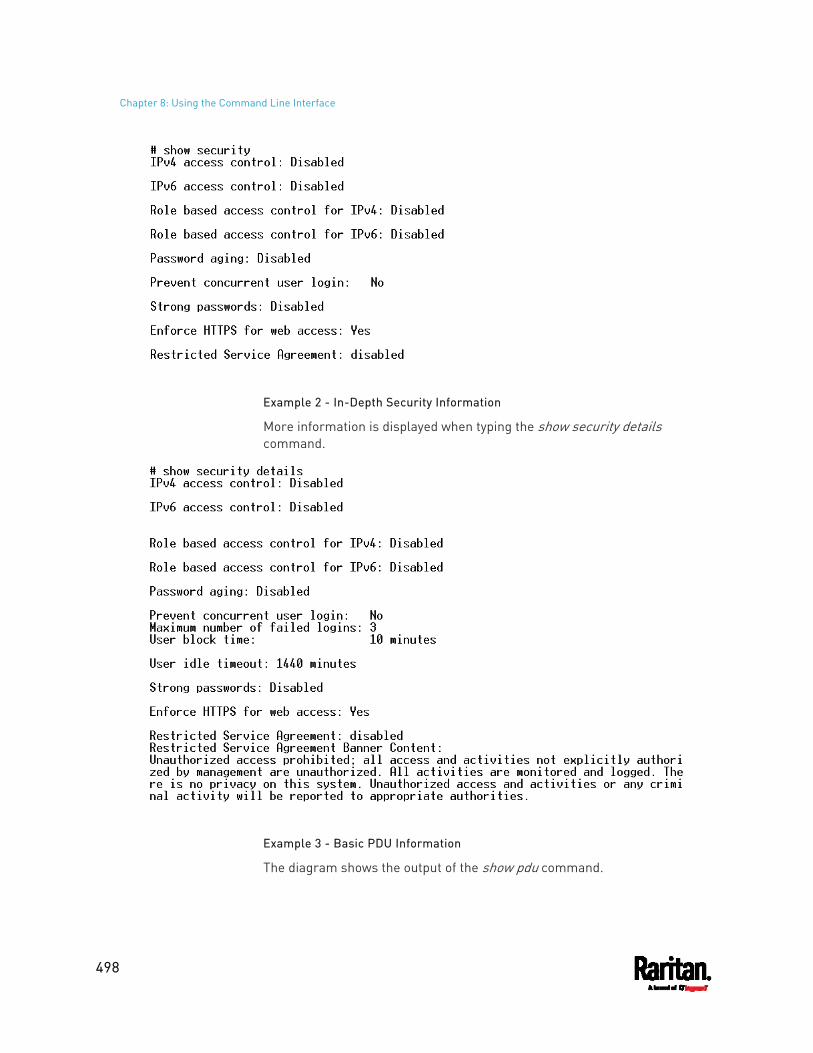
Chapter 8: Using the Command Line Interface
498
Example 2 - In-Depth Security Information
More information is displayed when typing the show security details command.
Example 3 - Basic PDU Information
The diagram shows the output of the show pdu command.
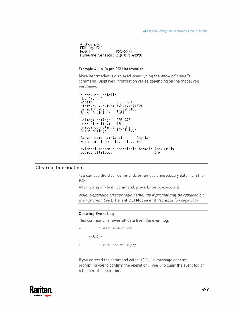
Chapter 8: Using the Command Line Interface
499
Example 4 - In-Depth PDU Information
More information is displayed when typing the show pdu details command. Displayed information varies depending on the model you purchased.
Clearing Information
You can use the clear commands to remove unnecessary data from the PX3.
After typing a "clear" command, press Enter to execute it.
Note: Depending on your login name, the # prompt may be replaced by the > prompt. See Different CLI Modes and Prompts (on page 465).
Clearing Event Log
This command removes all data from the event log.
# clear eventlog
-- OR --
# clear eventlog /y
If you entered the command without "/y," a message appears, prompting you to confirm the operation. Type y to clear the event log or n to abort the operation.
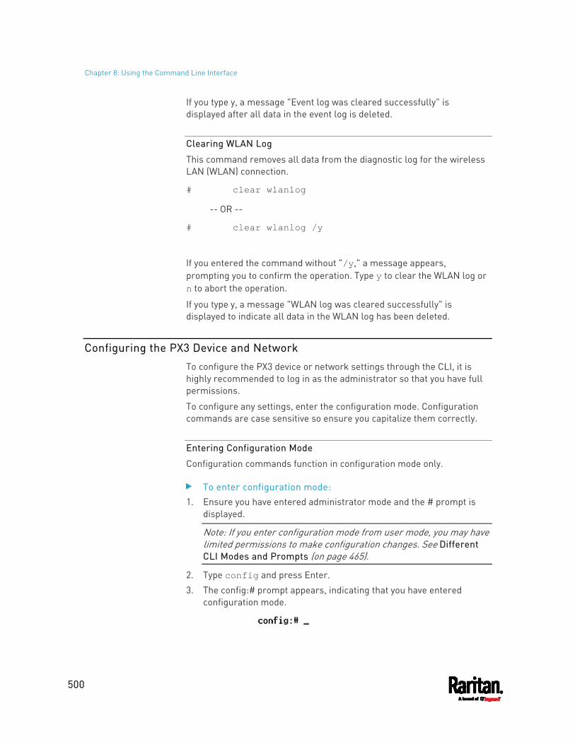
Chapter 8: Using the Command Line Interface
500
If you type y, a message "Event log was cleared successfully" is displayed after all data in the event log is deleted.
Clearing WLAN Log
This command removes all data from the diagnostic log for the wireless LAN (WLAN) connection.
# clear wlanlog
-- OR --
# clear wlanlog /y
If you entered the command without "/y," a message appears, prompting you to confirm the operation. Type y to clear the WLAN log or n to abort the operation.
If you type y, a message "WLAN log was cleared successfully" is displayed to indicate all data in the WLAN log has been deleted.
Configuring the PX3 Device and Network
To configure the PX3 device or network settings through the CLI, it is highly recommended to log in as the administrator so that you have full permissions.
To configure any settings, enter the configuration mode. Configuration commands are case sensitive so ensure you capitalize them correctly.
Entering Configuration Mode
Configuration commands function in configuration mode only.
To enter configuration mode: 1. Ensure you have entered administrator mode and the # prompt is
displayed.
Note: If you enter configuration mode from user mode, you may have limited permissions to make configuration changes. See Different CLI Modes and Prompts (on page 465).
2. Type config and press Enter.
3. The config:# prompt appears, indicating that you have entered configuration mode.
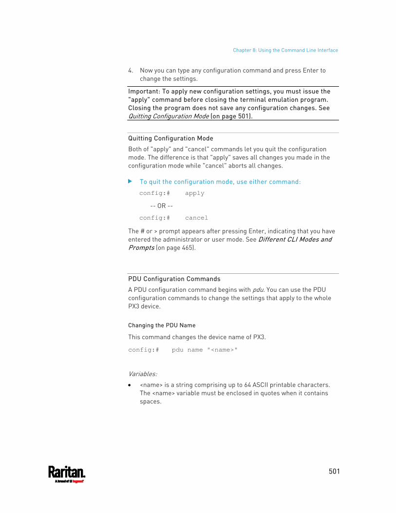
Chapter 8: Using the Command Line Interface
501
4. Now you can type any configuration command and press Enter to change the settings.
Important: To apply new configuration settings, you must issue the "apply" command before closing the terminal emulation program. Closing the program does not save any configuration changes. See Quitting Configuration Mode (on page 501).
Quitting Configuration Mode
Both of "apply" and "cancel" commands let you quit the configuration mode. The difference is that "apply" saves all changes you made in the configuration mode while "cancel" aborts all changes.
To quit the configuration mode, use either command:
config:# apply
-- OR --
config:# cancel
The # or > prompt appears after pressing Enter, indicating that you have entered the administrator or user mode. See Different CLI Modes and Prompts (on page 465).
PDU Configuration Commands
A PDU configuration command begins with pdu. You can use the PDU configuration commands to change the settings that apply to the whole PX3 device.
Changing the PDU Name
This command changes the device name of PX3.
config:# pdu name "<name>"
Variables: <name> is a string comprising up to 64 ASCII printable characters.
The <name> variable must be enclosed in quotes when it contains spaces.
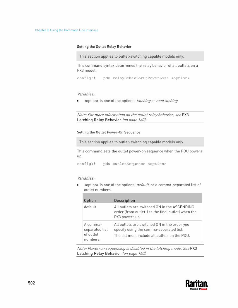
Chapter 8: Using the Command Line Interface
502
Setting the Outlet Relay Behavior
This section applies to outlet-switching capable models only.
This command syntax determines the relay behavior of all outlets on a PX3 model.
config:# pdu relayBehaviorOnPowerLoss <option>
Variables: <option> is one of the options: latching or nonLatching.
Note: For more information on the outlet relay behavior, see PX3 Latching Relay Behavior (on page 160).
Setting the Outlet Power-On Sequence
This section applies to outlet-switching capable models only.
This command sets the outlet power-on sequence when the PDU powers up.
config:# pdu outletSequence <option>
Variables: <option> is one of the options: default, or a comma-separated list of
outlet numbers.
Option Description
default All outlets are switched ON in the ASCENDING order (from outlet 1 to the final outlet) when the PX3 powers up.
A comma- separated list of outlet numbers
All outlets are switched ON in the order you specify using the comma-separated list. The list must include all outlets on the PDU.
Note: Power-on sequencing is disabled in the latching mode. See PX3 Latching Relay Behavior (on page 160).
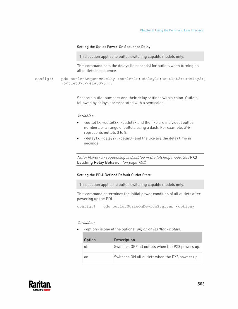
Chapter 8: Using the Command Line Interface
503
Setting the Outlet Power-On Sequence Delay
This section applies to outlet-switching capable models only.
This command sets the delays (in seconds) for outlets when turning on all outlets in sequence.
config:# pdu outletSequenceDelay <outlet1>:<delay1>;<outlet2>:<delay2>; <outlet3>:<delay3>;...
Separate outlet numbers and their delay settings with a colon. Outlets followed by delays are separated with a semicolon.
Variables: <outlet1>, <outlet2>, <outlet3> and the like are individual outlet
numbers or a range of outlets using a dash. For example, 3-8 represents outlets 3 to 8.
<delay1>, <delay2>, <delay3> and the like are the delay time in seconds.
Note: Power-on sequencing is disabled in the latching mode. See PX3 Latching Relay Behavior (on page 160).
Setting the PDU-Defined Default Outlet State
This section applies to outlet-switching capable models only.
This command determines the initial power condition of all outlets after powering up the PDU.
config:# pdu outletStateOnDeviceStartup <option>
Variables: <option> is one of the options: off, on or lastKnownState.
Option Description
off Switches OFF all outlets when the PX3 powers up.
on Switches ON all outlets when the PX3 powers up.
Chapter 8: Using the Command Line Interface
504
Option Description
lastKnownState Restores all outlets to the previous status before powering down the PX3 when the PDU powers up again.
Note: This feature does NOT take effect and cannot be configured on a PX3 device after the outlet relay is set to the "Latching" mode. See PX3 Latching Relay Behavior (on page 160).
Setting the PDU-Defined Cycling Power-Off Period
This section applies to outlet-switching capable models only.
This command sets the power-off period of the power cycling operation for all outlets.
config:# pdu cyclingPowerOffPeriod <timing>
Variables: <timing> is the time of the cycling power-off period in seconds,
which is an integer between 0 and 3600, or pduDefined for following the PDU-defined timing.
Setting the Inrush Guard Delay Time
This section applies to outlet-switching capable models only.
This command sets the inrush guard delay.
config:# pdu inrushGuardDelay <timing>
Variables: <timing> is a delay time between 100 and 100000 milliseconds.
Setting the Outlet Initialization Delay
This section applies to outlet-switching capable models only.
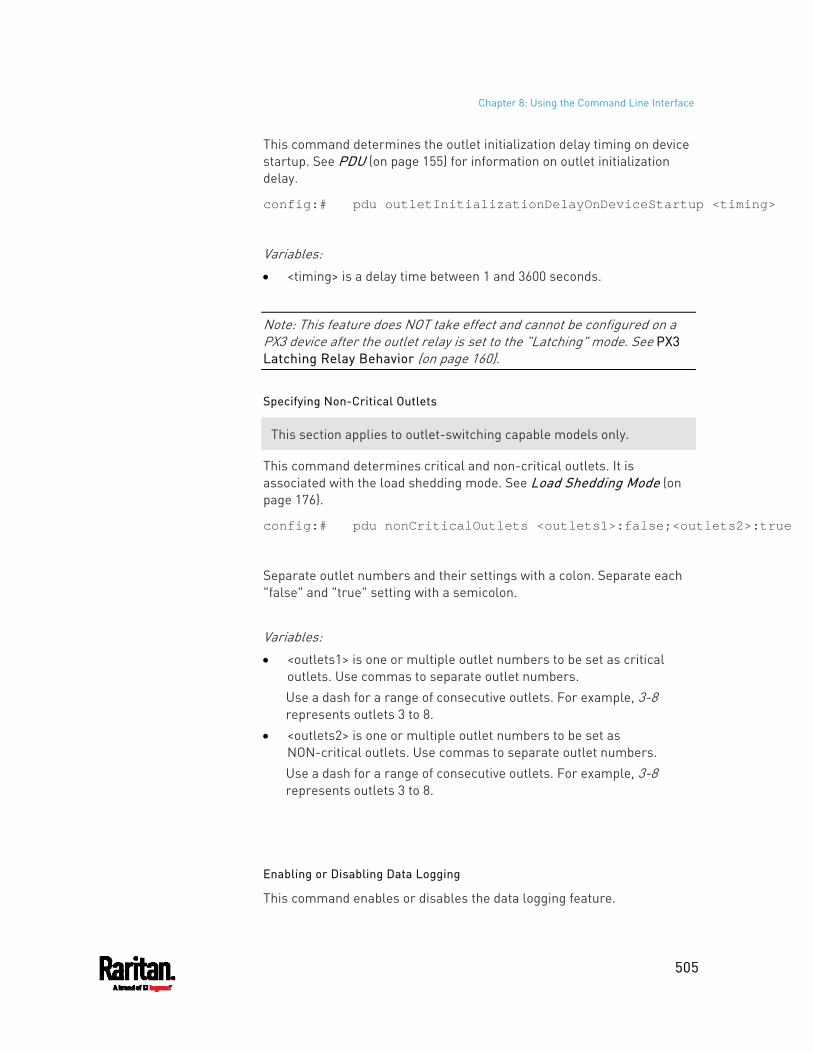
Chapter 8: Using the Command Line Interface
505
This command determines the outlet initialization delay timing on device startup. See PDU (on page 155) for information on outlet initialization delay.
config:# pdu outletInitializationDelayOnDeviceStartup <timing>
Variables: <timing> is a delay time between 1 and 3600 seconds.
Note: This feature does NOT take effect and cannot be configured on a PX3 device after the outlet relay is set to the "Latching" mode. See PX3 Latching Relay Behavior (on page 160).
Specifying Non-Critical Outlets
This section applies to outlet-switching capable models only.
This command determines critical and non-critical outlets. It is associated with the load shedding mode. See Load Shedding Mode (on page 176).
config:# pdu nonCriticalOutlets <outlets1>:false;<outlets2>:true
Separate outlet numbers and their settings with a colon. Separate each "false" and "true" setting with a semicolon.
Variables: <outlets1> is one or multiple outlet numbers to be set as critical
outlets. Use commas to separate outlet numbers. Use a dash for a range of consecutive outlets. For example, 3-8 represents outlets 3 to 8.
<outlets2> is one or multiple outlet numbers to be set as NON-critical outlets. Use commas to separate outlet numbers. Use a dash for a range of consecutive outlets. For example, 3-8 represents outlets 3 to 8.
Enabling or Disabling Data Logging
This command enables or disables the data logging feature.
Chapter 8: Using the Command Line Interface
506
config:# pdu dataRetrieval <option>
Variables: <option> is one of the options: enable or disable.
Option Description
enable Enables the data logging feature.
disable Disables the data logging feature.
For more information, see Setting Data Logging (on page 375).
Setting Data Logging Measurements Per Entry
This command defines the number of measurements accumulated per log entry.
config:# pdu measurementsPerLogEntry <number>
Variables: <number> is an integer between 1 and 600. The default is 60
samples per log entry.
For more information, see Setting Data Logging (on page 375).
Specifying the Device Altitude
This command specifies the altitude of your PX3 above sea level (in meters). You must specify the altitude of PX3 above sea level if a Raritan's DPX differential air pressure sensor is attached. This is because the device's altitude is associated with the altitude correction factor. See Altitude Correction Factors (on page 819).
config:# pdu deviceAltitude <altitude>
Variables: <altitude> is an integer between -425 and 3000 meters. Note that the lower limit "-425" is a negative value because some
locations are below the seal level.
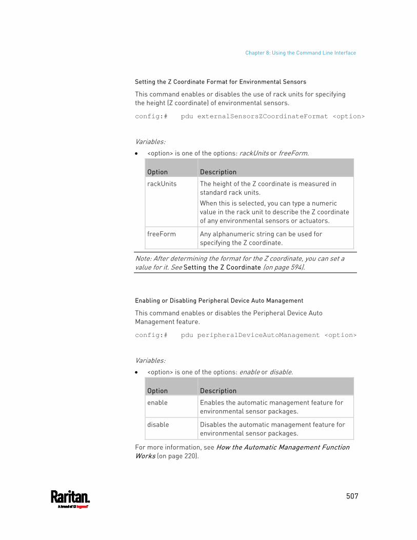
Chapter 8: Using the Command Line Interface
507
Setting the Z Coordinate Format for Environmental Sensors
This command enables or disables the use of rack units for specifying the height (Z coordinate) of environmental sensors.
config:# pdu externalSensorsZCoordinateFormat <option>
Variables: <option> is one of the options: rackUnits or freeForm.
Option Description
rackUnits The height of the Z coordinate is measured in standard rack units. When this is selected, you can type a numeric value in the rack unit to describe the Z coordinate of any environmental sensors or actuators.
freeForm Any alphanumeric string can be used for specifying the Z coordinate.
Note: After determining the format for the Z coordinate, you can set a value for it. See Setting the Z Coordinate (on page 594).
Enabling or Disabling Peripheral Device Auto Management
This command enables or disables the Peripheral Device Auto Management feature.
config:# pdu peripheralDeviceAutoManagement <option>
Variables: <option> is one of the options: enable or disable.
Option Description
enable Enables the automatic management feature for environmental sensor packages.
disable Disables the automatic management feature for environmental sensor packages.
For more information, see How the Automatic Management Function Works (on page 220).
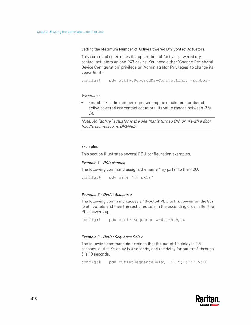
Chapter 8: Using the Command Line Interface
508
Setting the Maximum Number of Active Powered Dry Contact Actuators
This command determines the upper limit of "active" powered dry contact actuators on one PX3 device. You need either 'Change Peripheral Device Configuration' privilege or 'Administrator Privileges' to change its upper limit.
config:# pdu activePoweredDryContactLimit <number>
Variables: <number> is the number representing the maximum number of
active powered dry contact actuators. Its value ranges between 0 to 24.
Note: An "active" actuator is the one that is turned ON, or, if with a door handle connected, is OPENED.
Examples
This section illustrates several PDU configuration examples.
Example 1 - PDU Naming
The following command assigns the name "my px12" to the PDU.
config:# pdu name "my px12"
Example 2 - Outlet Sequence
The following command causes a 10-outlet PDU to first power on the 8th to 6th outlets and then the rest of outlets in the ascending order after the PDU powers up.
config:# pdu outletSequence 8-6,1-5,9,10
Example 3 - Outlet Sequence Delay
The following command determines that the outlet 1's delay is 2.5 seconds, outlet 2's delay is 3 seconds, and the delay for outlets 3 through 5 is 10 seconds.
config:# pdu outletSequenceDelay 1:2.5;2:3;3-5:10
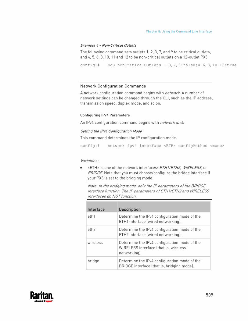
Chapter 8: Using the Command Line Interface
509
Example 4 - Non-Critical Outlets
The following command sets outlets 1, 2, 3, 7, and 9 to be critical outlets, and 4, 5, 6, 8, 10, 11 and 12 to be non-critical outlets on a 12-outlet PX3.
config:# pdu nonCriticalOutlets 1-3,7,9:false;4-6,8,10-12:true
Network Configuration Commands
A network configuration command begins with network. A number of network settings can be changed through the CLI, such as the IP address, transmission speed, duplex mode, and so on.
Configuring IPv4 Parameters
An IPv4 configuration command begins with network ipv4.
Setting the IPv4 Configuration Mode
This command determines the IP configuration mode.
config:# network ipv4 interface <ETH> configMethod <mode>
Variables: <ETH> is one of the network interfaces: ETH1/ETH2, WIRELESS, or
BRIDGE. Note that you must choose/configure the bridge interface if your PX3 is set to the bridging mode.
Note: In the bridging mode, only the IP parameters of the BRIDGE interface function. The IP parameters of ETH1/ETH2 and WIRELESS interfaces do NOT function.
Interface Description
eth1 Determine the IPv4 configuration mode of the ETH1 interface (wired networking).
eth2 Determine the IPv4 configuration mode of the ETH2 interface (wired networking).
wireless Determine the IPv4 configuration mode of the WIRELESS interface (that is, wireless networking).
bridge Determine the IPv4 configuration mode of the BRIDGE interface (that is, bridging mode).

Chapter 8: Using the Command Line Interface
510
<mode> is one of the modes: dhcp or static.
Mode Description
dhcp The IPv4 configuration mode is set to DHCP.
static The IPv4 configuration mode is set to static IP address.
Setting the IPv4 Preferred Host Name
After selecting DHCP as the IPv4 configuration mode, you can specify the preferred host name, which is optional. The following is the command:
config:# network ipv4 interface <ETH> preferredHostName <name>
Variables: <ETH> is one of the network interfaces: ETH1/ETH2, WIRELESS, or
BRIDGE. Note that you must choose/configure the bridge interface if your PX3 is set to the bridging mode.
Note: In the bridging mode, only the IP parameters of the BRIDGE interface function. The IP parameters of ETH1/ETH2 and WIRELESS interfaces do NOT function.
Interface Description
eth1 Determine the IPv4 preferred host name of the ETH1 interface (that is, wired networking).
eth2 Determine the IPv4 preferred host name of the ETH2 interface (that is, wired networking).
wireless Determine the IPv4 preferred host name of the WIRELESS interface (that is, wireless networking).
bridge Determine the IPv4 preferred host name of the BRIDGE interface (that is, bridging mode).
<name> is a host name which: Consists of alphanumeric characters and/or hyphens Cannot begin or end with a hyphen Cannot contain more than 63 characters Cannot contain punctuation marks, spaces, and other symbols
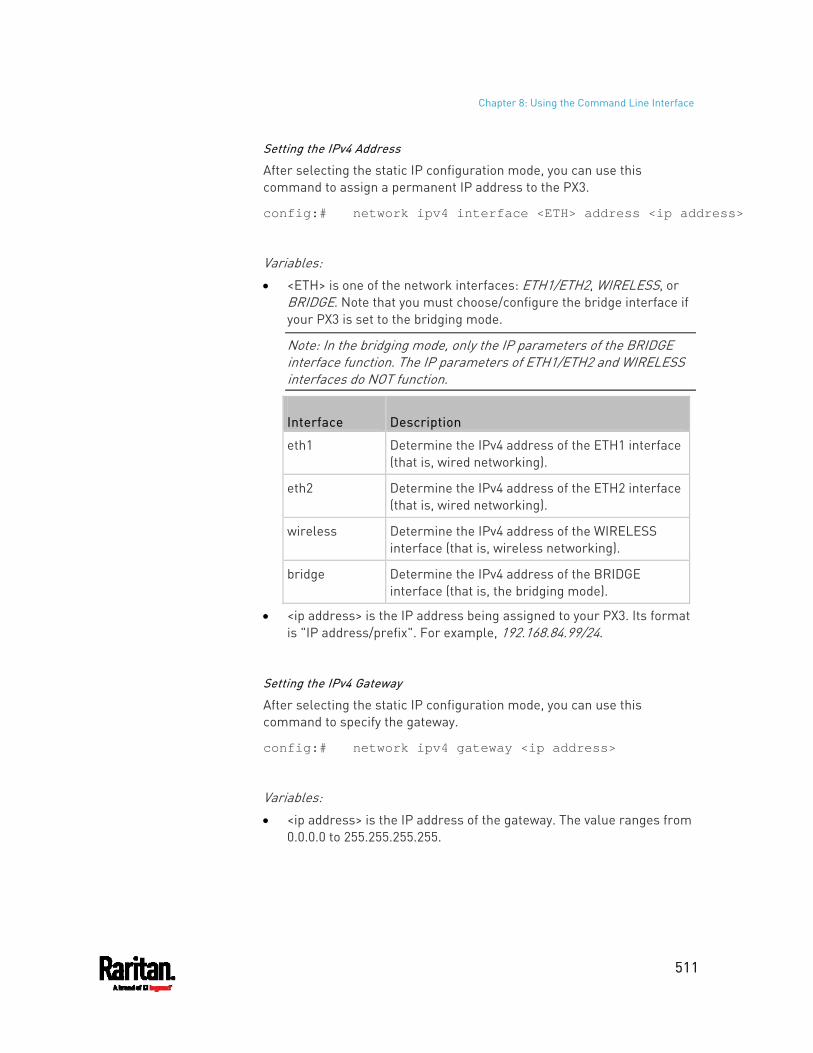
Chapter 8: Using the Command Line Interface
511
Setting the IPv4 Address
After selecting the static IP configuration mode, you can use this command to assign a permanent IP address to the PX3.
config:# network ipv4 interface <ETH> address <ip address>
Variables: <ETH> is one of the network interfaces: ETH1/ETH2, WIRELESS, or
BRIDGE. Note that you must choose/configure the bridge interface if your PX3 is set to the bridging mode.
Note: In the bridging mode, only the IP parameters of the BRIDGE interface function. The IP parameters of ETH1/ETH2 and WIRELESS interfaces do NOT function.
Interface Description
eth1 Determine the IPv4 address of the ETH1 interface (that is, wired networking).
eth2 Determine the IPv4 address of the ETH2 interface (that is, wired networking).
wireless Determine the IPv4 address of the WIRELESS interface (that is, wireless networking).
bridge Determine the IPv4 address of the BRIDGE interface (that is, the bridging mode).
<ip address> is the IP address being assigned to your PX3. Its format is "IP address/prefix". For example, 192.168.84.99/24.
Setting the IPv4 Gateway
After selecting the static IP configuration mode, you can use this command to specify the gateway.
config:# network ipv4 gateway <ip address>
Variables: <ip address> is the IP address of the gateway. The value ranges from
0.0.0.0 to 255.255.255.255.
Chapter 8: Using the Command Line Interface
512
Setting IPv4 Static Routes
If the IPv4 network mode is set to static IP and your local network contains two subnets, you can configure static routes to enable or disable communications between the PX3 and devices in the other subnet.
These commands are prefixed with network ipv4 staticRoutes.
Depending on whether the other network is directly reachable or not, there are two methods for adding a static route. For further information, see Static Route Examples (on page 265).
Method 1: add a static route when the other network is NOT directly reachable:
config:# network ipv4 staticRoutes add <dest-1> <hop>
Method 2: add a static route when the other network is directly reachable:
config:# network ipv4 staticRoutes add <dest-1> interface <ETH>
Delete an existing static route:
config:# network ipv4 staticRoutes delete <route_ID>
Modify an existing static route:
config:# network ipv4 staticRoutes modify <route_ID> <dest-2> <hop>
-- OR --
config:# network ipv4 staticRoutes modify <route_ID> <dest-2> interface <ETH>
Variables:
Chapter 8: Using the Command Line Interface
513
<dest-1> is a combination of the IP address and subnet mask of the other subnet. The format is IP address/subnet mask.
<hop> is the IP address of the next hop router. <ETH> is one of the interfaces: ETH1/ETH2, WIRELESS and BRIDGE.
Type "bridge" only when your PX3 is in the bridging mode. <route_ID> is the ID number of the route setting which you want to
delete or modify. <dest-2> is a modified route setting that will replace the original
route setting. Its format is IP address/subnet mask. You can modify either the IP address or the subnet mask or both.
Configuring IPv6 Parameters
An IPv6 configuration command begins with network ipv6.
Setting the IPv6 Configuration Mode
This command determines the IP configuration mode.
config:# network ipv6 interface <ETH> configMethod <mode>
Variables: <ETH> is one of the network interfaces: ETH1/ETH2, WIRELESS, or
BRIDGE. Note that you must choose/configure the bridge interface if your PX3 is set to the bridging mode.
Note: In the bridging mode, only the IP parameters of the BRIDGE interface function. The IP parameters of ETH1/ETH2 and WIRELESS interfaces do NOT function.
Interface Description
eth1 Determine the IPv6 configuration mode of the ETH1 interface (wired networking).
eth2 Determine the IPv6 configuration mode of the ETH2 interface (wired networking).
wireless Determine the IPv6 configuration mode of the WIRELESS interface (that is, wireless networking).
bridge Determine the IPv6 configuration mode of the BRIDGE interface (that is, bridging mode).
Chapter 8: Using the Command Line Interface
514
<mode> is one of the modes: automatic or static.
Mode Description
automatic The IPv6 configuration mode is set to automatic.
static The IPv6 configuration mode is set to static IP address.
Setting the IPv6 Preferred Host Name
After selecting DHCP as the IPv6 configuration mode, you can specify the preferred host name, which is optional. The following is the command:
config:# network ipv6 interface <ETH> preferredHostName <name>
Variables: <ETH> is one of the network interfaces: ETH1/ETH2, WIRELESS, or
BRIDGE. Note that you must choose/configure the bridge interface if your PX3 is set to the bridging mode.
Note: In the bridging mode, only the IP parameters of the BRIDGE interface function. The IP parameters of ETH1/ETH2 and WIRELESS interfaces do NOT function.
Interface Description
eth1 Determine the IPv6 preferred host name of the ETH1 interface (wired networking).
eth2 Determine the IPv6 preferred host name of the ETH2 interface (wired networking).
wireless Determine the IPv6 preferred host name of the WIRELESS interface (that is, wireless networking).
bridge Determine the IPv6 preferred host name of the BRIDGE interface (that is, bridging mode).
<name> is a host name which: Consists of alphanumeric characters and/or hyphens Cannot begin or end with a hyphen Cannot contain more than 63 characters
Cannot contain punctuation marks, spaces, and other symbols
Chapter 8: Using the Command Line Interface
515
Setting the IPv6 Address
After selecting the static IP configuration mode, you can use this command to assign a permanent IP address to the PX3.
config:# network ipv6 interface <ETH> address <ip address>
Variables: <ETH> is one of the network interfaces: ETH1/ETH2, WIRELESS, or
BRIDGE. Note that you must choose/configure the bridge interface if your PX3 is set to the bridging mode.
Note: In the bridging mode, only the IP parameters of the BRIDGE interface function. The IP parameters of ETH1/ETH2 and WIRELESS interfaces do NOT function.
Interface Description
eth1 Determine the IPv6 address of the ETH1 interface (wired networking).
eth2 Determine the IPv6 address of the ETH2 interface (wired networking).
wireless Determine the IPv6 address of the WIRELESS interface (that is, wireless networking).
bridge Determine the IPv6 address of the BRIDGE interface (that is, the bridging mode).
<ip address> is the IP address being assigned to your PX3. This value uses the IPv6 address format. Note that you must add /xx, which indicates a prefix length of bits such as /64, to the end of this IPv6 address.
Setting the IPv6 Gateway
After selecting the static IP configuration mode, you can use this command to specify the gateway.
config:# network ipv6 gateway <ip address>
Variables: <ip address> is the IP address of the gateway. This value uses the
IPv6 address format.
Chapter 8: Using the Command Line Interface
516
Setting IPv6 Static Routes
If the IPv6 network mode is set to static IP and your local network contains two subnets, you can configure static routes to enable or disable communications between the PX3 and devices in the other subnet.
These commands are prefixed with network ipv6 staticRoutes.
Depending on whether the other network is directly reachable or not, there are two methods for adding a static route. For further information, see Static Route Examples (on page 265).
Method 1: add a static route when the other network is NOT directly reachable:
config:# network ipv6 staticRoutes add <dest-1> <hop>
Method 2: add a static route when the other network is directly reachable:
config:# network ipv6 staticRoutes add <dest-1> interface <ETH>
Delete an existing static route:
config:# network ipv6 staticRoutes delete <route_ID>
Modify an existing static route:
config:# network ipv6 staticRoutes modify <route_ID> <dest-2> <hop>
-- OR --
config:# network ipv6 staticRoutes modify <route_ID> <dest-2> interface <ETH>
Variables:
Chapter 8: Using the Command Line Interface
517
<dest-1> is the IP address and prefix length of the subnet where the PX3 belongs. The format is IP address/prefix length.
<hop> is the IP address of the next hop router. <ETH> is one of the interfaces: ETH1/ETH2, WIRELESS and BRIDGE.
Type "bridge" only when your PX3 is in the bridging mode. <route_ID> is the ID number of the route setting which you want to
delete or modify. <dest-2> is a modified route setting that will replace the original
route setting. Its format is IP address/prefix length. You can modify either the IP address or the prefix length or both.
Configuring DNS Parameters
Use the following commands to configure static DNS-related settings.
Specify the primary DNS server:
config:# network dns firstServer <ip address>
Specify the secondary DNS server:
config:# network dns secondServer <ip address>
Specify the third DNS server:
config:# network dns thirdServer <ip address>
Specify one or multiple optional DNS search suffixes:
config:# network dns searchSuffixes <suffix1>
-- OR --
config:# network dns searchSuffixes <suffix1>,<suffix2>,<suffix3>,...,<suffix6>
Determine which IP address is used when the DNS server returns both IPv4 and IPv6 addresses:
config:# network dns resolverPreference <resolver>
Variables:
Chapter 8: Using the Command Line Interface
518
<ip address> is the IP address of the DNS server. <suffix1>, <suffix2>, and the like are the DNS suffixes that
automatically apply when searching for any device via PX3. For example, <suffix1> can be raritan.com, and <suffix2> can be legrand.com. You can specify up to 6 suffixes by separating them with commas.
<resolver> is one of the options: preferV4 or preferV6.
Option Description
preferV4 Use the IPv4 addresses returned by the DNS server.
preferV6 Use the IPv6 addresses returned by the DNS server.
Setting LAN Interface Parameters
A LAN interface configuration command begins with network ethernet.
Enabling or Disabling the LAN Interface
This command enables or disables the LAN interface.
config:# network ethernet <ETH> enabled <option>
Variables: <ETH> is one of the options -- eth1 or eth2.
Option Description
eth1 ETH1 port
eth2 ETH2 port
<option> is one of the options: true or false.
Option Description
true The specified network interface is enabled.
false The specified network interface is disabled.
Chapter 8: Using the Command Line Interface
519
Changing the LAN Interface Speed
This command determines the LAN interface speed.
config:# network ethernet <ETH> speed <option>
Variables: <ETH> is one of the options -- eth1 or eth2.
Option Description
eth1 ETH1 port
eth2 ETH2 port
<option> is one of the options: auto, 10Mbps, 100Mbps or 1000Mbps.
Option Description
auto System determines the optimum LAN speed through auto-negotiation.
10Mbps The LAN speed is always 10 Mbps.
100Mbps The LAN speed is always 100 Mbps.
1000Mbps The LAN speed is always 1000 Mbps.
Changing the LAN Duplex Mode
This command determines the LAN interface duplex mode.
config:# network ethernet <ETH> duplexMode <mode>
Variables: <ETH> is one of the options -- eth1 or eth2.
Option Description
eth1 ETH1 port
eth2 ETH2 port
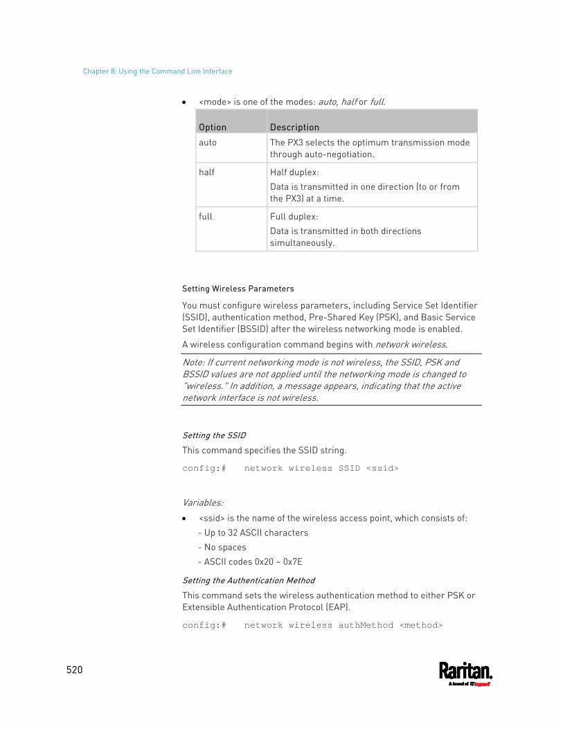
Chapter 8: Using the Command Line Interface
520
<mode> is one of the modes: auto, half or full.
Option Description
auto The PX3 selects the optimum transmission mode through auto-negotiation.
half Half duplex: Data is transmitted in one direction (to or from the PX3) at a time.
full Full duplex: Data is transmitted in both directions simultaneously.
Setting Wireless Parameters
You must configure wireless parameters, including Service Set Identifier (SSID), authentication method, Pre-Shared Key (PSK), and Basic Service Set Identifier (BSSID) after the wireless networking mode is enabled.
A wireless configuration command begins with network wireless.
Note: If current networking mode is not wireless, the SSID, PSK and BSSID values are not applied until the networking mode is changed to "wireless." In addition, a message appears, indicating that the active network interface is not wireless.
Setting the SSID
This command specifies the SSID string.
config:# network wireless SSID <ssid>
Variables: <ssid> is the name of the wireless access point, which consists of:
- Up to 32 ASCII characters - No spaces - ASCII codes 0x20 ~ 0x7E
Setting the Authentication Method
This command sets the wireless authentication method to either PSK or Extensible Authentication Protocol (EAP).
config:# network wireless authMethod <method>
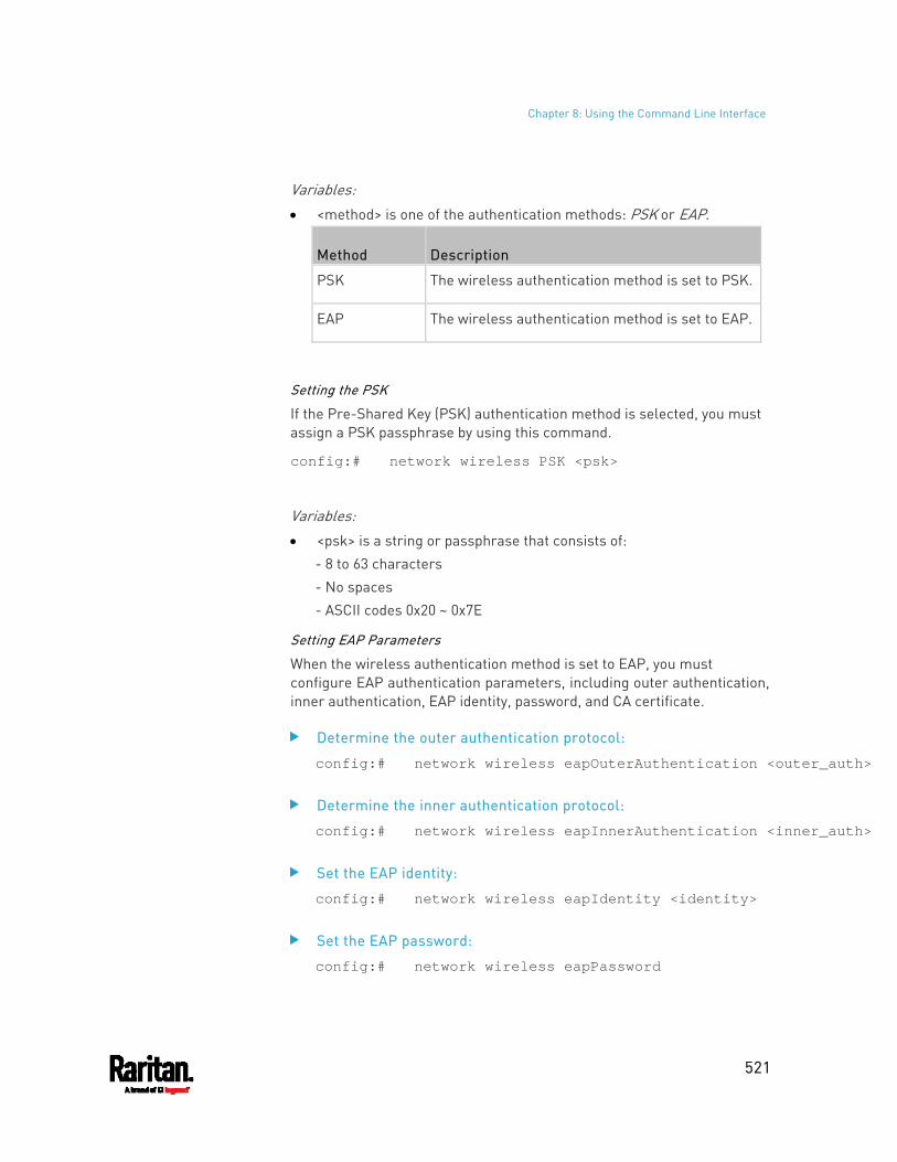
Chapter 8: Using the Command Line Interface
521
Variables: <method> is one of the authentication methods: PSK or EAP.
Method Description
PSK The wireless authentication method is set to PSK.
EAP The wireless authentication method is set to EAP.
Setting the PSK
If the Pre-Shared Key (PSK) authentication method is selected, you must assign a PSK passphrase by using this command.
config:# network wireless PSK <psk>
Variables: <psk> is a string or passphrase that consists of:
- 8 to 63 characters - No spaces - ASCII codes 0x20 ~ 0x7E
Setting EAP Parameters
When the wireless authentication method is set to EAP, you must configure EAP authentication parameters, including outer authentication, inner authentication, EAP identity, password, and CA certificate.
Determine the outer authentication protocol:
config:# network wireless eapOuterAuthentication <outer_auth>
Determine the inner authentication protocol:
config:# network wireless eapInnerAuthentication <inner_auth>
Set the EAP identity:
config:# network wireless eapIdentity <identity>
Set the EAP password:
config:# network wireless eapPassword
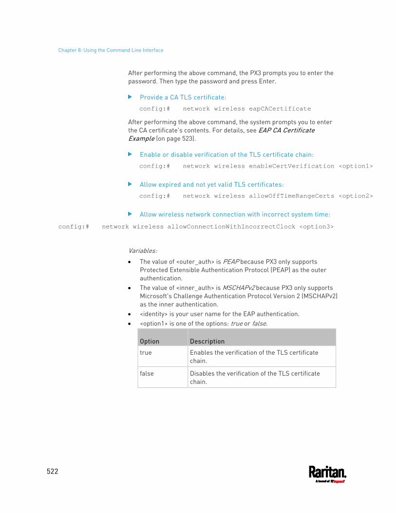
Chapter 8: Using the Command Line Interface
522
After performing the above command, the PX3 prompts you to enter the password. Then type the password and press Enter.
Provide a CA TLS certificate:
config:# network wireless eapCACertificate
After performing the above command, the system prompts you to enter the CA certificate's contents. For details, see EAP CA Certificate Example (on page 523).
Enable or disable verification of the TLS certificate chain:
config:# network wireless enableCertVerification <option1>
Allow expired and not yet valid TLS certificates:
config:# network wireless allowOffTimeRangeCerts <option2>
Allow wireless network connection with incorrect system time:
config:# network wireless allowConnectionWithIncorrectClock <option3>
Variables: The value of <outer_auth> is PEAP because PX3 only supports
Protected Extensible Authentication Protocol (PEAP) as the outer authentication.
The value of <inner_auth> is MSCHAPv2 because PX3 only supports Microsoft's Challenge Authentication Protocol Version 2 (MSCHAPv2) as the inner authentication.
<identity> is your user name for the EAP authentication. <option1> is one of the options: true or false.
Option Description
true Enables the verification of the TLS certificate chain.
false Disables the verification of the TLS certificate chain.
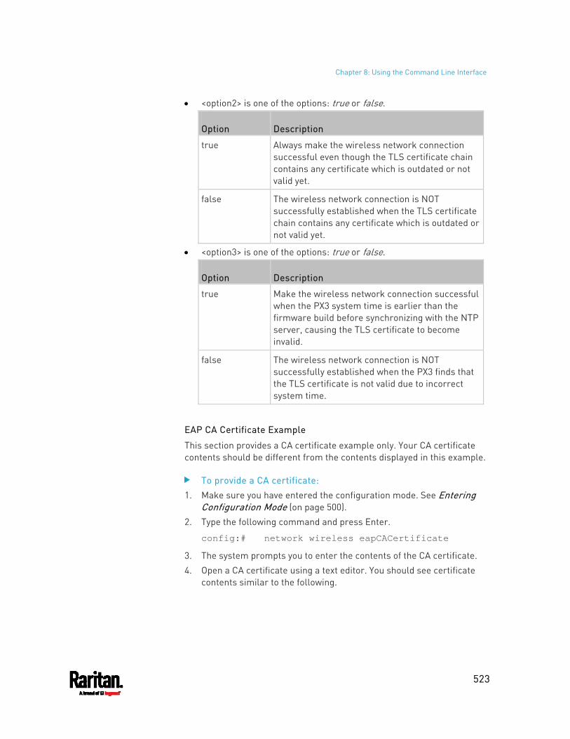
Chapter 8: Using the Command Line Interface
523
<option2> is one of the options: true or false.
Option Description
true Always make the wireless network connection successful even though the TLS certificate chain contains any certificate which is outdated or not valid yet.
false The wireless network connection is NOT successfully established when the TLS certificate chain contains any certificate which is outdated or not valid yet.
<option3> is one of the options: true or false.
Option Description
true Make the wireless network connection successful when the PX3 system time is earlier than the firmware build before synchronizing with the NTP server, causing the TLS certificate to become invalid.
false The wireless network connection is NOT successfully established when the PX3 finds that the TLS certificate is not valid due to incorrect system time.
EAP CA Certificate Example
This section provides a CA certificate example only. Your CA certificate contents should be different from the contents displayed in this example.
To provide a CA certificate: 1. Make sure you have entered the configuration mode. See Entering
Configuration Mode (on page 500). 2. Type the following command and press Enter.
config:# network wireless eapCACertificate
3. The system prompts you to enter the contents of the CA certificate. 4. Open a CA certificate using a text editor. You should see certificate
contents similar to the following.
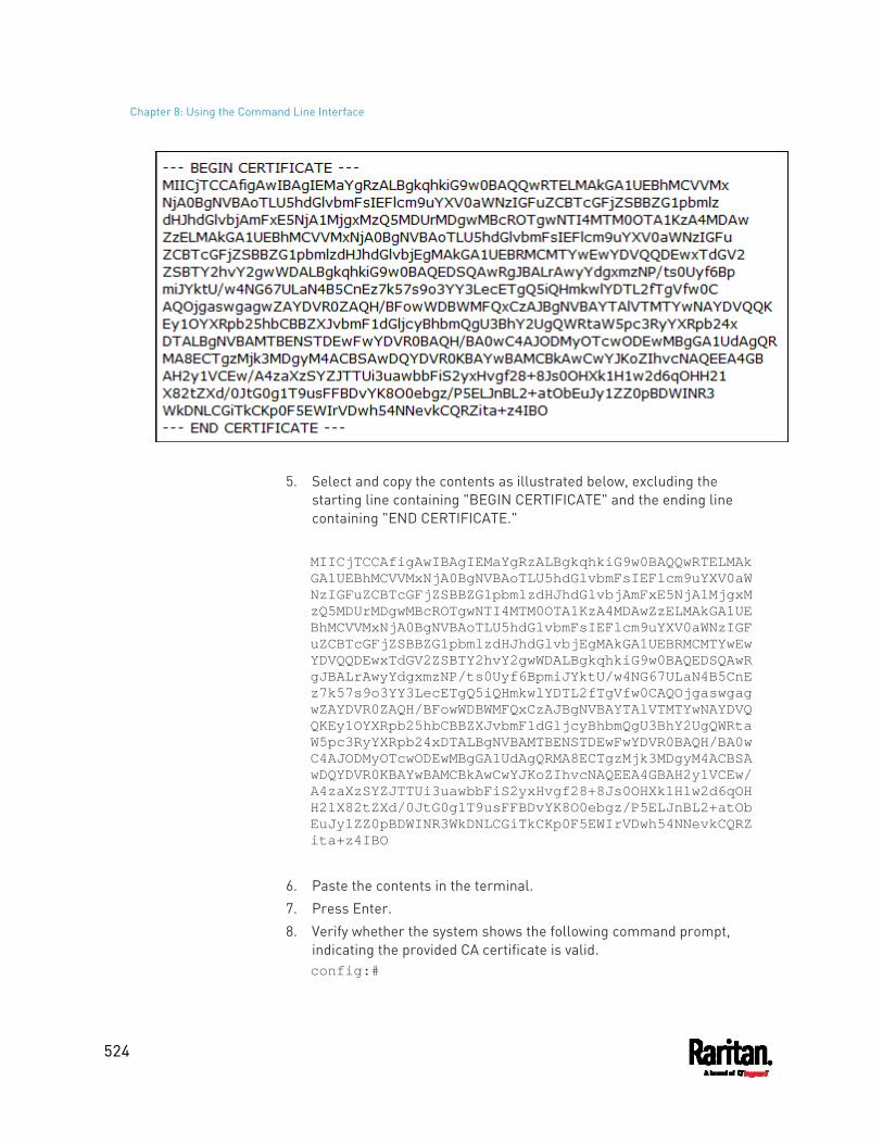
Chapter 8: Using the Command Line Interface
524
5. Select and copy the contents as illustrated below, excluding the starting line containing "BEGIN CERTIFICATE" and the ending line containing "END CERTIFICATE." MIICjTCCAfigAwIBAgIEMaYgRzALBgkqhkiG9w0BAQQwRTELMAkGA1UEBhMCVVMxNjA0BgNVBAoTLU5hdGlvbmFsIEFlcm9uYXV0aWNzIGFuZCBTcGFjZSBBZG1pbmlzdHJhdGlvbjAmFxE5NjA1MjgxMzQ5MDUrMDgwMBcROTgwNTI4MTM0OTA1KzA4MDAwZzELMAkGA1UEBhMCVVMxNjA0BgNVBAoTLU5hdGlvbmFsIEFlcm9uYXV0aWNzIGFuZCBTcGFjZSBBZG1pbmlzdHJhdGlvbjEgMAkGA1UEBRMCMTYwEwYDVQQDEwxTdGV2ZSBTY2hvY2gwWDALBgkqhkiG9w0BAQEDSQAwRgJBALrAwyYdgxmzNP/ts0Uyf6BpmiJYktU/w4NG67ULaN4B5CnEz7k57s9o3YY3LecETgQ5iQHmkwlYDTL2fTgVfw0CAQOjgaswgagwZAYDVR0ZAQH/BFowWDBWMFQxCzAJBgNVBAYTAlVTMTYwNAYDVQQKEy1OYXRpb25hbCBBZXJvbmF1dGljcyBhbmQgU3BhY2UgQWRtaW5pc3RyYXRpb24xDTALBgNVBAMTBENSTDEwFwYDVR0BAQH/BA0wC4AJODMyOTcwODEwMBgGA1UdAgQRMA8ECTgzMjk3MDgyM4ACBSAwDQYDVR0KBAYwBAMCBkAwCwYJKoZIhvcNAQEEA4GBAH2y1VCEw/A4zaXzSYZJTTUi3uawbbFiS2yxHvgf28+8Js0OHXk1H1w2d6qOHH21X82tZXd/0JtG0g1T9usFFBDvYK8O0ebgz/P5ELJnBL2+atObEuJy1ZZ0pBDWINR3WkDNLCGiTkCKp0F5EWIrVDwh54NNevkCQRZita+z4IBO
6. Paste the contents in the terminal. 7. Press Enter. 8. Verify whether the system shows the following command prompt,
indicating the provided CA certificate is valid. config:#
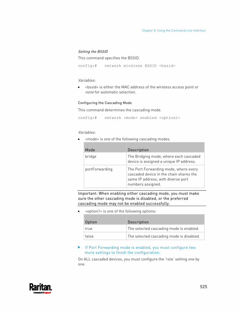
Chapter 8: Using the Command Line Interface
525
Setting the BSSID
This command specifies the BSSID.
config:# network wireless BSSID <bssid>
Variables: <bssid> is either the MAC address of the wireless access point or
none for automatic selection.
Configuring the Cascading Mode
This command determines the cascading mode.
config:# network <mode> enabled <option1>
Variables: <mode> is one of the following cascading modes.
Mode Description
bridge The Bridging mode, where each cascaded device is assigned a unique IP address.
portForwarding The Port Forwarding mode, where every cascaded device in the chain shares the same IP address, with diverse port numbers assigned.
Important: When enabling either cascading mode, you must make sure the other cascading mode is disabled, or the preferred cascading mode may not be enabled successfully.
<option1> is one of the following options:
Option Description
true The selected cascading mode is enabled.
false The selected cascading mode is disabled.
If Port Forwarding mode is enabled, you must configure two more settings to finish the configuration:
On ALL cascaded devices, you must configure the 'role' setting one by one.
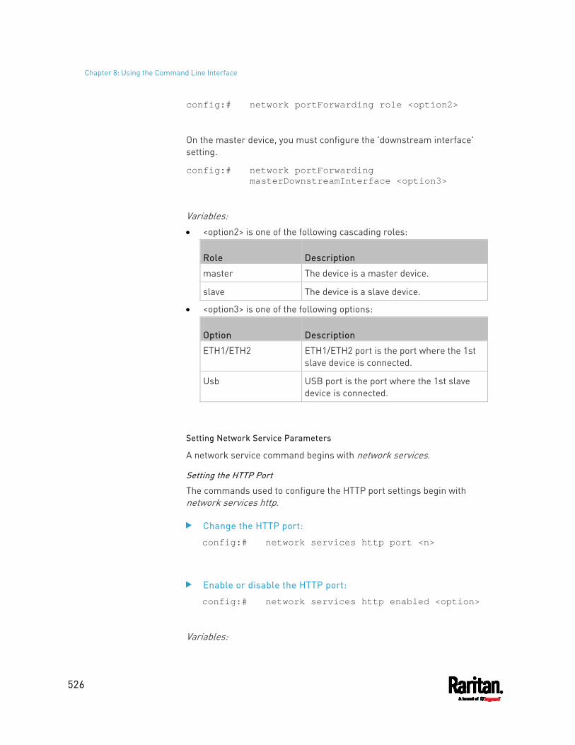
Chapter 8: Using the Command Line Interface
526
config:# network portForwarding role <option2>
On the master device, you must configure the 'downstream interface' setting.
config:# network portForwarding masterDownstreamInterface <option3>
Variables: <option2> is one of the following cascading roles:
Role Description
master The device is a master device.
slave The device is a slave device.
<option3> is one of the following options:
Option Description
ETH1/ETH2 ETH1/ETH2 port is the port where the 1st slave device is connected.
Usb USB port is the port where the 1st slave device is connected.
Setting Network Service Parameters
A network service command begins with network services.
Setting the HTTP Port
The commands used to configure the HTTP port settings begin with network services http.
Change the HTTP port:
config:# network services http port <n>
Enable or disable the HTTP port:
config:# network services http enabled <option>
Variables:
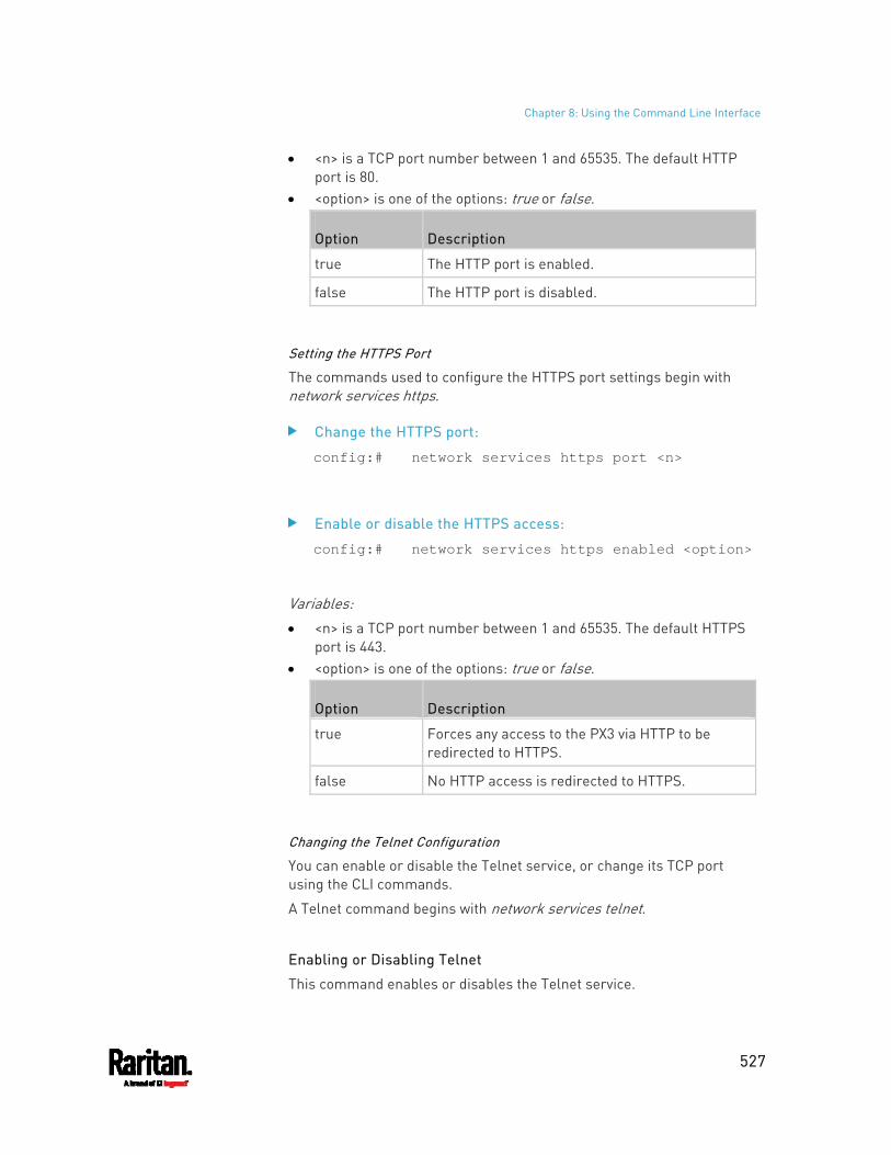
Chapter 8: Using the Command Line Interface
527
<n> is a TCP port number between 1 and 65535. The default HTTP port is 80.
<option> is one of the options: true or false.
Option Description
true The HTTP port is enabled.
false The HTTP port is disabled.
Setting the HTTPS Port
The commands used to configure the HTTPS port settings begin with network services https.
Change the HTTPS port:
config:# network services https port <n>
Enable or disable the HTTPS access:
config:# network services https enabled <option>
Variables: <n> is a TCP port number between 1 and 65535. The default HTTPS
port is 443. <option> is one of the options: true or false.
Option Description
true Forces any access to the PX3 via HTTP to be redirected to HTTPS.
false No HTTP access is redirected to HTTPS.
Changing the Telnet Configuration
You can enable or disable the Telnet service, or change its TCP port using the CLI commands.
A Telnet command begins with network services telnet.
Enabling or Disabling Telnet
This command enables or disables the Telnet service.
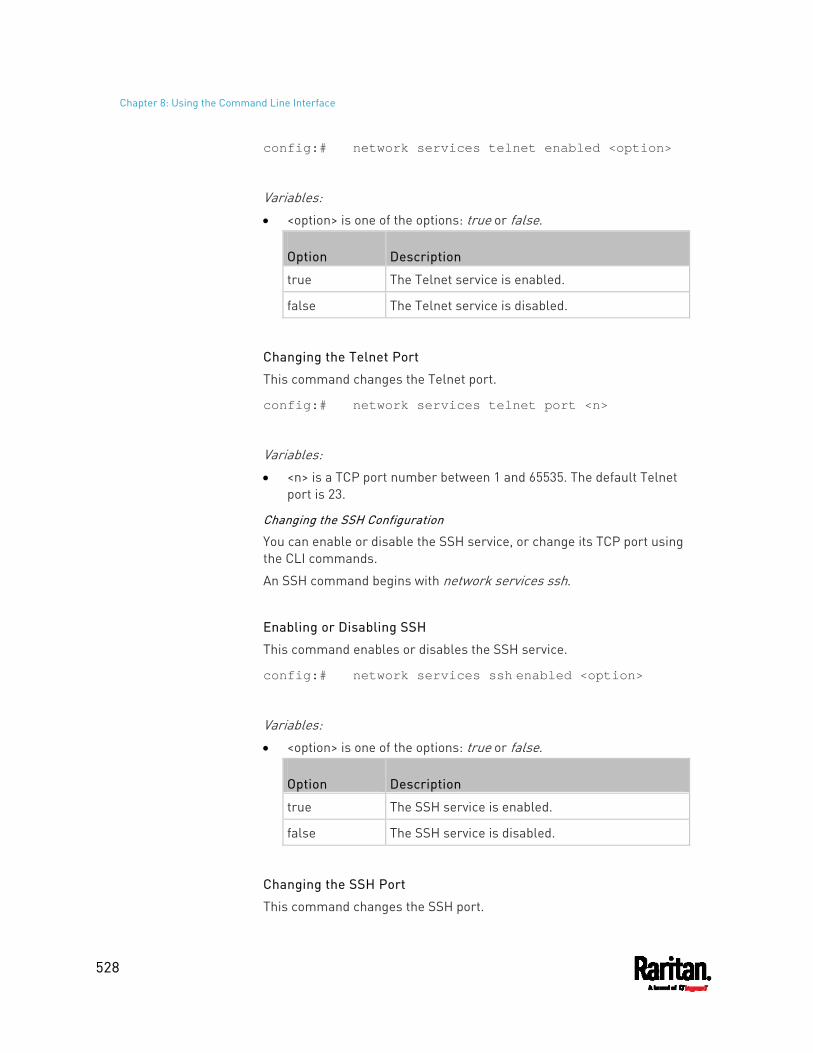
Chapter 8: Using the Command Line Interface
528
config:# network services telnet enabled <option>
Variables: <option> is one of the options: true or false.
Option Description
true The Telnet service is enabled.
false The Telnet service is disabled.
Changing the Telnet Port
This command changes the Telnet port.
config:# network services telnet port <n>
Variables: <n> is a TCP port number between 1 and 65535. The default Telnet
port is 23.
Changing the SSH Configuration
You can enable or disable the SSH service, or change its TCP port using the CLI commands.
An SSH command begins with network services ssh.
Enabling or Disabling SSH
This command enables or disables the SSH service.
config:# network services ssh enabled <option>
Variables: <option> is one of the options: true or false.
Option Description
true The SSH service is enabled.
false The SSH service is disabled.
Changing the SSH Port
This command changes the SSH port.
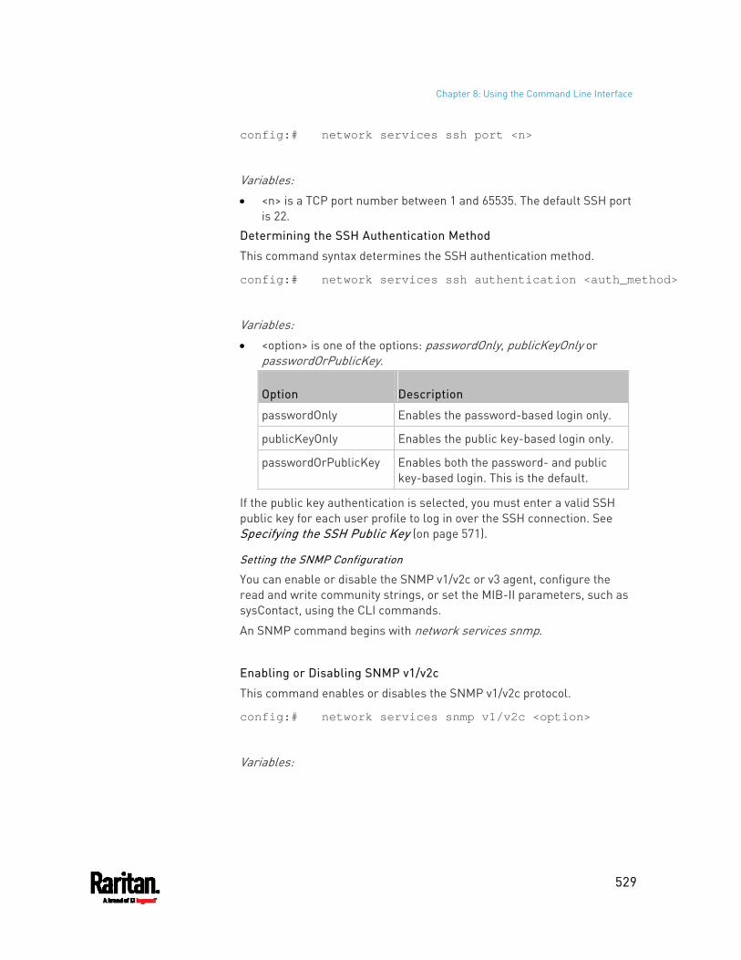
Chapter 8: Using the Command Line Interface
529
config:# network services ssh port <n>
Variables: <n> is a TCP port number between 1 and 65535. The default SSH port
is 22.
Determining the SSH Authentication Method
This command syntax determines the SSH authentication method.
config:# network services ssh authentication <auth_method>
Variables: <option> is one of the options: passwordOnly, publicKeyOnly or
passwordOrPublicKey.
Option Description
passwordOnly Enables the password-based login only.
publicKeyOnly Enables the public key-based login only.
passwordOrPublicKey Enables both the password- and public key-based login. This is the default.
If the public key authentication is selected, you must enter a valid SSH public key for each user profile to log in over the SSH connection. See Specifying the SSH Public Key (on page 571).
Setting the SNMP Configuration
You can enable or disable the SNMP v1/v2c or v3 agent, configure the read and write community strings, or set the MIB-II parameters, such as sysContact, using the CLI commands.
An SNMP command begins with network services snmp.
Enabling or Disabling SNMP v1/v2c
This command enables or disables the SNMP v1/v2c protocol.
config:# network services snmp v1/v2c <option>
Variables:
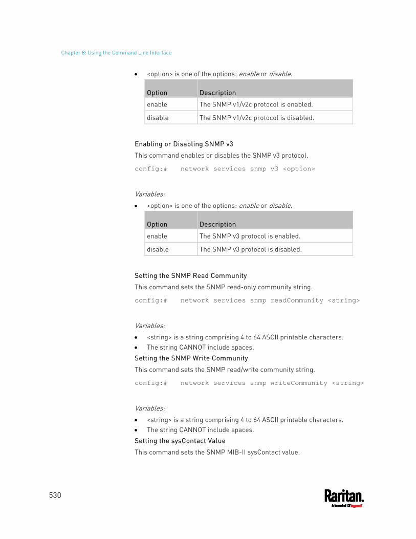
Chapter 8: Using the Command Line Interface
530
<option> is one of the options: enable or disable.
Option Description
enable The SNMP v1/v2c protocol is enabled.
disable The SNMP v1/v2c protocol is disabled.
Enabling or Disabling SNMP v3
This command enables or disables the SNMP v3 protocol.
config:# network services snmp v3 <option>
Variables: <option> is one of the options: enable or disable.
Option Description
enable The SNMP v3 protocol is enabled.
disable The SNMP v3 protocol is disabled.
Setting the SNMP Read Community
This command sets the SNMP read-only community string.
config:# network services snmp readCommunity <string>
Variables: <string> is a string comprising 4 to 64 ASCII printable characters. The string CANNOT include spaces.
Setting the SNMP Write Community
This command sets the SNMP read/write community string.
config:# network services snmp writeCommunity <string>
Variables: <string> is a string comprising 4 to 64 ASCII printable characters. The string CANNOT include spaces.
Setting the sysContact Value
This command sets the SNMP MIB-II sysContact value.
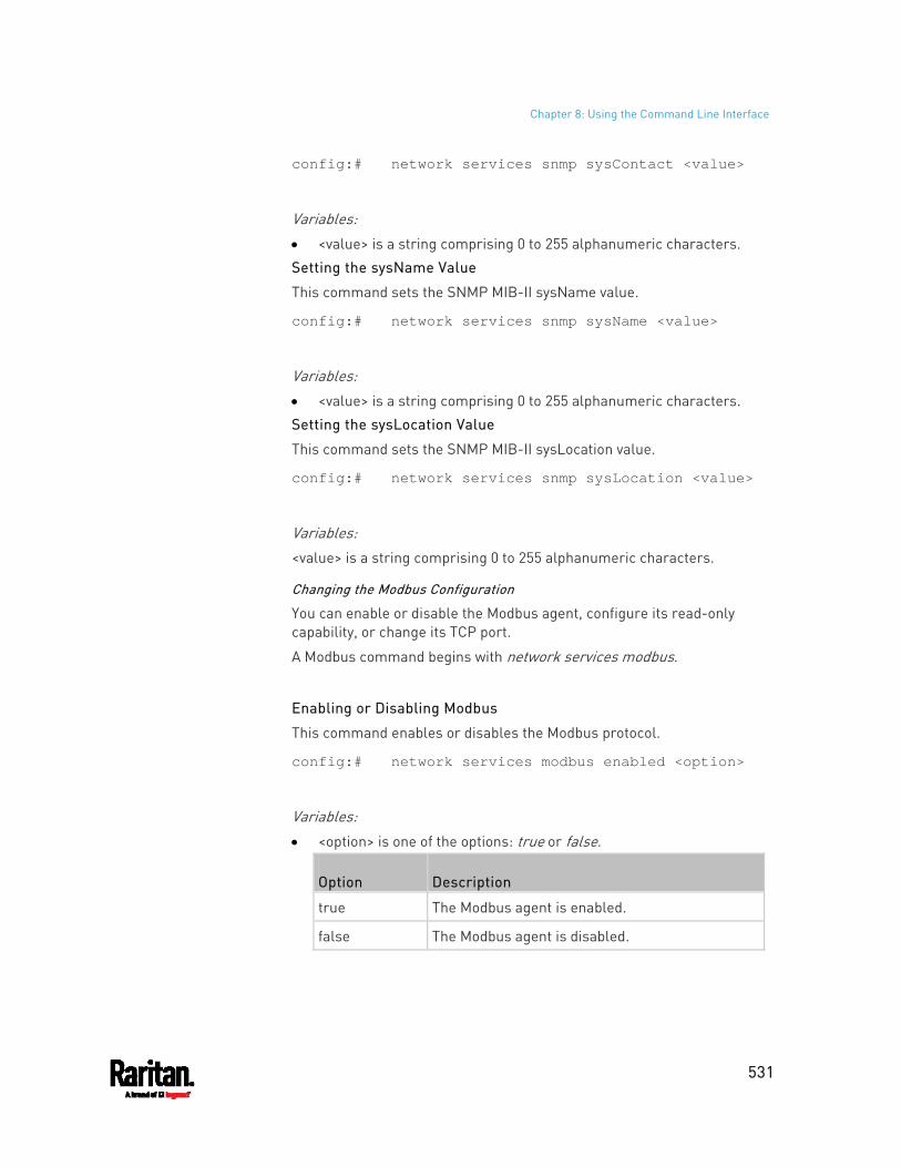
Chapter 8: Using the Command Line Interface
531
config:# network services snmp sysContact <value>
Variables: <value> is a string comprising 0 to 255 alphanumeric characters.
Setting the sysName Value
This command sets the SNMP MIB-II sysName value.
config:# network services snmp sysName <value>
Variables: <value> is a string comprising 0 to 255 alphanumeric characters.
Setting the sysLocation Value
This command sets the SNMP MIB-II sysLocation value.
config:# network services snmp sysLocation <value>
Variables: <value> is a string comprising 0 to 255 alphanumeric characters.
Changing the Modbus Configuration
You can enable or disable the Modbus agent, configure its read-only capability, or change its TCP port.
A Modbus command begins with network services modbus.
Enabling or Disabling Modbus
This command enables or disables the Modbus protocol.
config:# network services modbus enabled <option>
Variables: <option> is one of the options: true or false.
Option Description
true The Modbus agent is enabled.
false The Modbus agent is disabled.
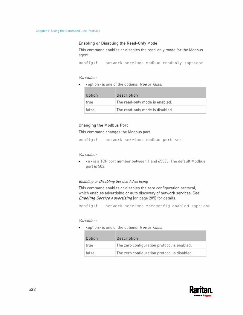
Chapter 8: Using the Command Line Interface
532
Enabling or Disabling the Read-Only Mode
This command enables or disables the read-only mode for the Modbus agent.
config:# network services modbus readonly <option>
Variables: <option> is one of the options: true or false.
Option Description
true The read-only mode is enabled.
false The read-only mode is disabled.
Changing the Modbus Port
This command changes the Modbus port.
config:# network services modbus port <n>
Variables: <n> is a TCP port number between 1 and 65535. The default Modbus
port is 502.
Enabling or Disabling Service Advertising
This command enables or disables the zero configuration protocol, which enables advertising or auto discovery of network services. See Enabling Service Advertising (on page 285) for details.
config:# network services zeroconfig enabled <option>
Variables: <option> is one of the options: true or false.
Option Description
true The zero configuration protocol is enabled.
false The zero configuration protocol is disabled.
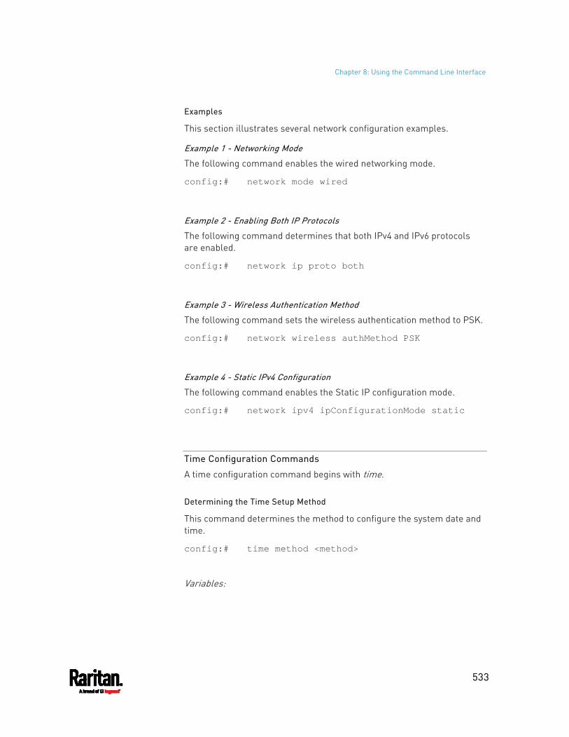
Chapter 8: Using the Command Line Interface
533
Examples
This section illustrates several network configuration examples.
Example 1 - Networking Mode
The following command enables the wired networking mode.
config:# network mode wired
Example 2 - Enabling Both IP Protocols
The following command determines that both IPv4 and IPv6 protocols are enabled.
config:# network ip proto both
Example 3 - Wireless Authentication Method
The following command sets the wireless authentication method to PSK.
config:# network wireless authMethod PSK
Example 4 - Static IPv4 Configuration
The following command enables the Static IP configuration mode.
config:# network ipv4 ipConfigurationMode static
Time Configuration Commands
A time configuration command begins with time.
Determining the Time Setup Method
This command determines the method to configure the system date and time.
config:# time method <method>
Variables:
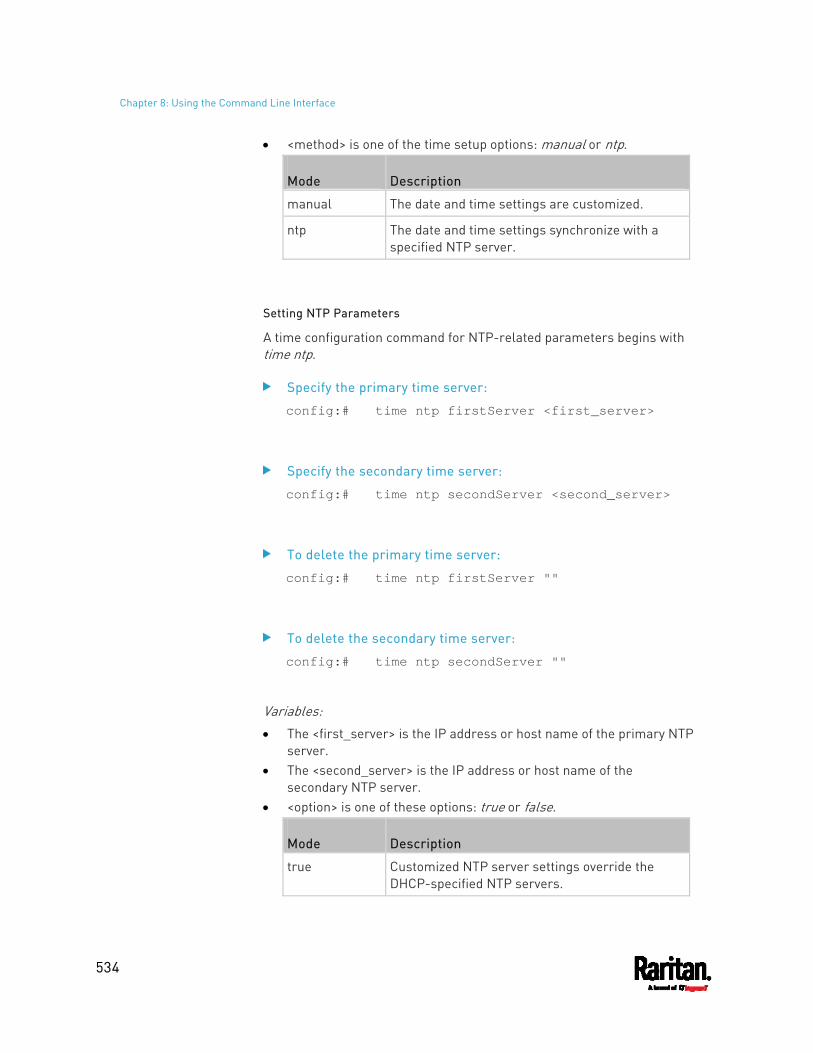
Chapter 8: Using the Command Line Interface
534
<method> is one of the time setup options: manual or ntp.
Mode Description
manual The date and time settings are customized.
ntp The date and time settings synchronize with a specified NTP server.
Setting NTP Parameters
A time configuration command for NTP-related parameters begins with time ntp.
Specify the primary time server:
config:# time ntp firstServer <first_server>
Specify the secondary time server:
config:# time ntp secondServer <second_server>
To delete the primary time server:
config:# time ntp firstServer ""
To delete the secondary time server:
config:# time ntp secondServer ""
Variables: The <first_server> is the IP address or host name of the primary NTP
server. The <second_server> is the IP address or host name of the
secondary NTP server. <option> is one of these options: true or false.
Mode Description
true Customized NTP server settings override the DHCP-specified NTP servers.
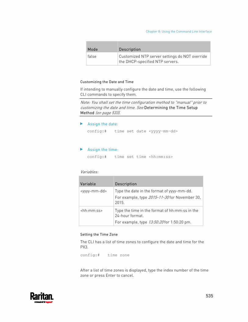
Chapter 8: Using the Command Line Interface
535
Mode Description
false Customized NTP server settings do NOT override the DHCP-specified NTP servers.
Customizing the Date and Time
If intending to manually configure the date and time, use the following CLI commands to specify them.
Note: You shall set the time configuration method to "manual" prior to customizing the date and time. See Determining the Time Setup Method (on page 533).
Assign the date:
config:# time set date <yyyy-mm-dd>
Assign the time:
config:# time set time <hh:mm:ss>
Variables:
Variable Description
<yyyy-mm-dd> Type the date in the format of yyyy-mm-dd. For example, type 2015-11-30 for November 30, 2015.
<hh:mm:ss> Type the time in the format of hh:mm:ss in the 24-hour format. For example, type 13:50:20 for 1:50:20 pm.
Setting the Time Zone
The CLI has a list of time zones to configure the date and time for the PX3.
config:# time zone
After a list of time zones is displayed, type the index number of the time zone or press Enter to cancel.
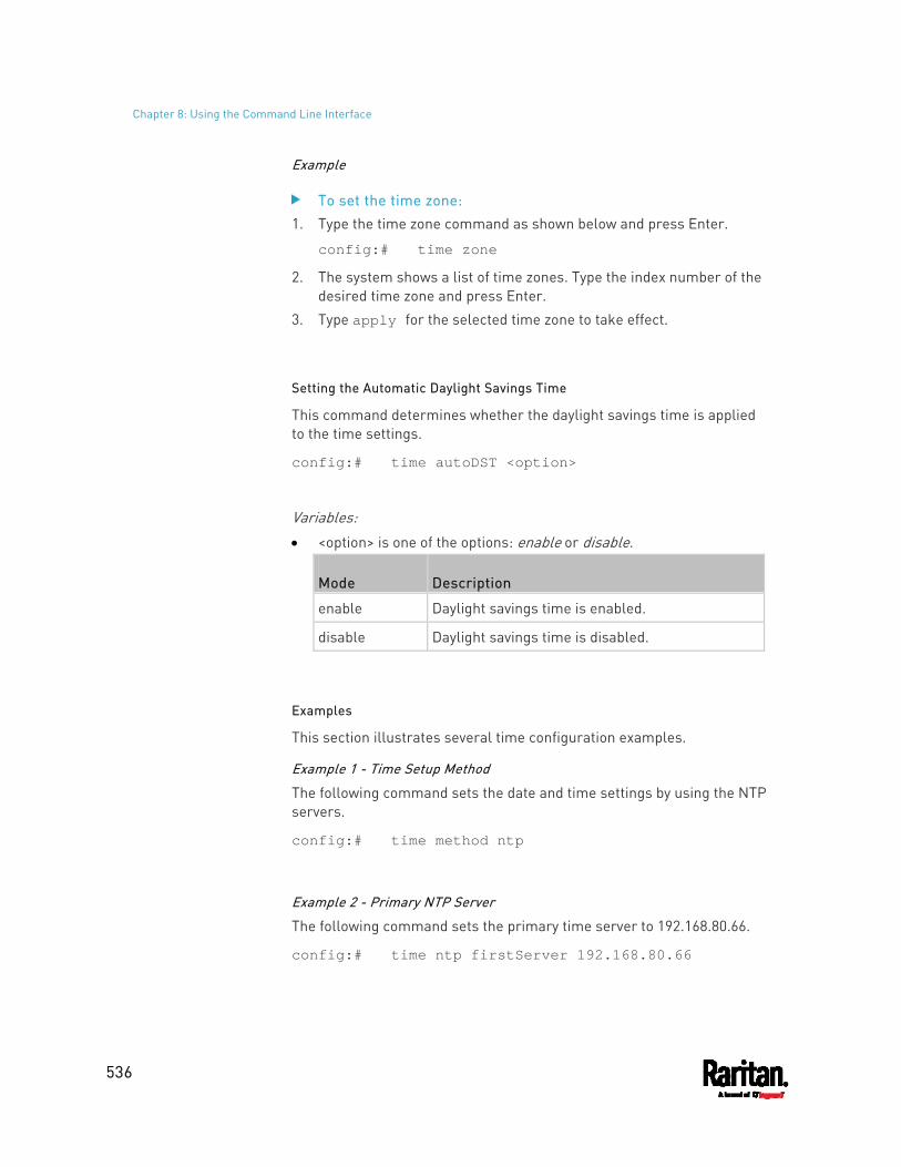
Chapter 8: Using the Command Line Interface
536
Example
To set the time zone: 1. Type the time zone command as shown below and press Enter.
config:# time zone
2. The system shows a list of time zones. Type the index number of the desired time zone and press Enter.
3. Type apply for the selected time zone to take effect.
Setting the Automatic Daylight Savings Time
This command determines whether the daylight savings time is applied to the time settings.
config:# time autoDST <option>
Variables: <option> is one of the options: enable or disable.
Mode Description
enable Daylight savings time is enabled.
disable Daylight savings time is disabled.
Examples
This section illustrates several time configuration examples.
Example 1 - Time Setup Method
The following command sets the date and time settings by using the NTP servers.
config:# time method ntp
Example 2 - Primary NTP Server
The following command sets the primary time server to 192.168.80.66.
config:# time ntp firstServer 192.168.80.66
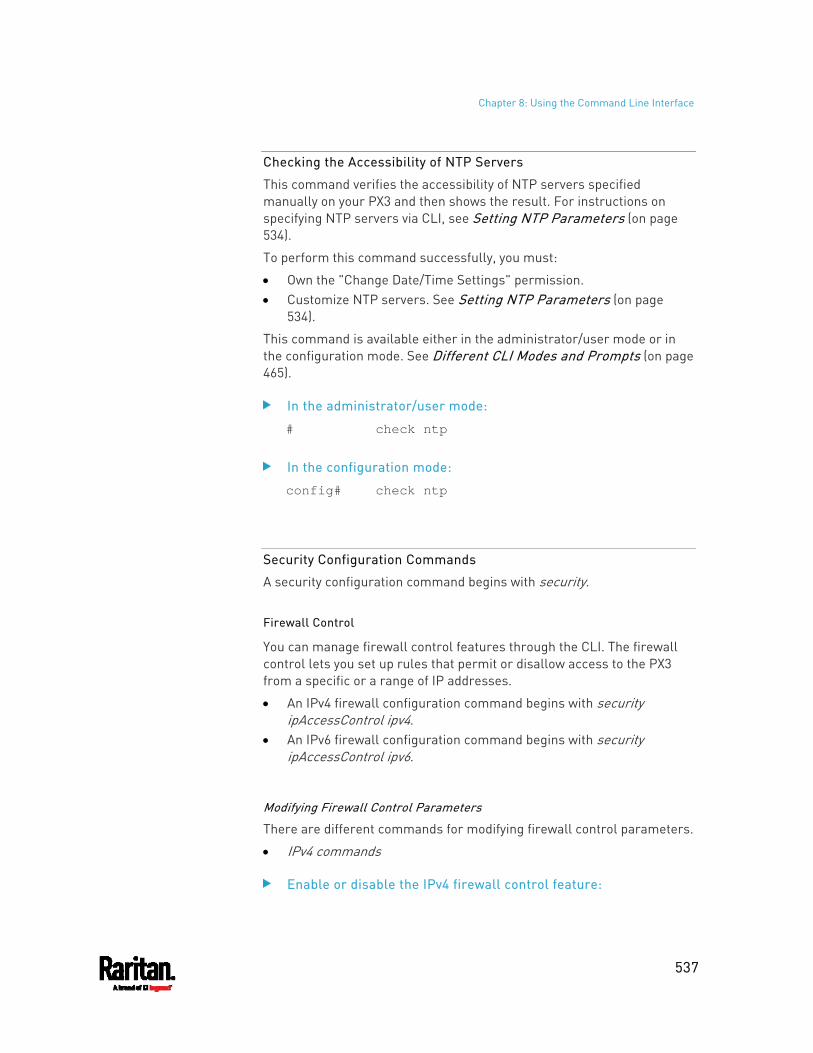
Chapter 8: Using the Command Line Interface
537
Checking the Accessibility of NTP Servers
This command verifies the accessibility of NTP servers specified manually on your PX3 and then shows the result. For instructions on specifying NTP servers via CLI, see Setting NTP Parameters (on page 534).
To perform this command successfully, you must:
Own the "Change Date/Time Settings" permission. Customize NTP servers. See Setting NTP Parameters (on page
534).
This command is available either in the administrator/user mode or in the configuration mode. See Different CLI Modes and Prompts (on page 465).
In the administrator/user mode:
# check ntp
In the configuration mode:
config# check ntp
Security Configuration Commands
A security configuration command begins with security.
Firewall Control
You can manage firewall control features through the CLI. The firewall control lets you set up rules that permit or disallow access to the PX3 from a specific or a range of IP addresses.
An IPv4 firewall configuration command begins with security ipAccessControl ipv4.
An IPv6 firewall configuration command begins with security ipAccessControl ipv6.
Modifying Firewall Control Parameters
There are different commands for modifying firewall control parameters.
IPv4 commands
Enable or disable the IPv4 firewall control feature:
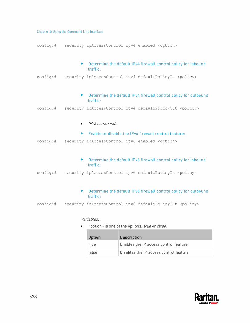
Chapter 8: Using the Command Line Interface
538
config:# security ipAccessControl ipv4 enabled <option>
Determine the default IPv4 firewall control policy for inbound traffic:
config:# security ipAccessControl ipv4 defaultPolicyIn <policy>
Determine the default IPv4 firewall control policy for outbound traffic:
config:# security ipAccessControl ipv4 defaultPolicyOut <policy>
IPv6 commands
Enable or disable the IPv6 firewall control feature:
config:# security ipAccessControl ipv6 enabled <option>
Determine the default IPv6 firewall control policy for inbound traffic:
config:# security ipAccessControl ipv6 defaultPolicyIn <policy>
Determine the default IPv6 firewall control policy for outbound traffic:
config:# security ipAccessControl ipv6 defaultPolicyOut <policy>
Variables: <option> is one of the options: true or false.
Option Description
true Enables the IP access control feature.
false Disables the IP access control feature.
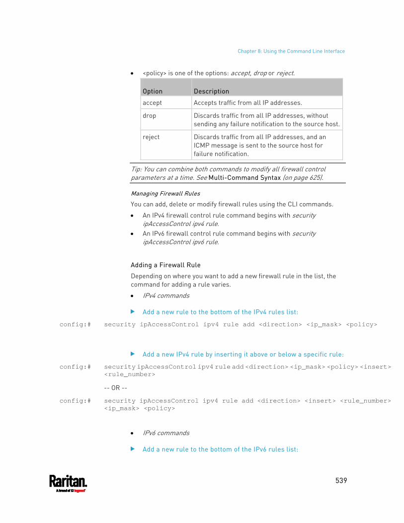
Chapter 8: Using the Command Line Interface
539
<policy> is one of the options: accept, drop or reject.
Option Description
accept Accepts traffic from all IP addresses.
drop Discards traffic from all IP addresses, without sending any failure notification to the source host.
reject Discards traffic from all IP addresses, and an ICMP message is sent to the source host for failure notification.
Tip: You can combine both commands to modify all firewall control parameters at a time. See Multi-Command Syntax (on page 625).
Managing Firewall Rules
You can add, delete or modify firewall rules using the CLI commands.
An IPv4 firewall control rule command begins with security ipAccessControl ipv4 rule.
An IPv6 firewall control rule command begins with security ipAccessControl ipv6 rule.
Adding a Firewall Rule
Depending on where you want to add a new firewall rule in the list, the command for adding a rule varies.
IPv4 commands
Add a new rule to the bottom of the IPv4 rules list:
config:# security ipAccessControl ipv4 rule add <direction> <ip_mask> <policy>
Add a new IPv4 rule by inserting it above or below a specific rule:
config:# security ipAccessControl ipv4 rule add <direction> <ip_mask> <policy> <insert> <rule_number>
-- OR --
config:# security ipAccessControl ipv4 rule add <direction> <insert> <rule_number> <ip_mask> <policy>
IPv6 commands
Add a new rule to the bottom of the IPv6 rules list:
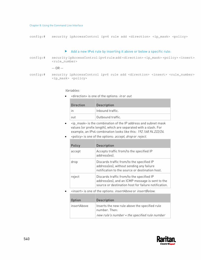
Chapter 8: Using the Command Line Interface
540
config:# security ipAccessControl ipv6 rule add <direction> <ip_mask> <policy>
Add a new IPv6 rule by inserting it above or below a specific rule:
config:# security ipAccessControl ipv6 rule add <direction> <ip_mask> <policy> <insert> <rule_number>
-- OR --
config:# security ipAccessControl ipv6 rule add <direction> <insert> <rule_number> <ip_mask> <policy>
Variables: <direction> is one of the options: in or out.
Direction Description
in Inbound traffic.
out Outbound traffic.
<ip_mask> is the combination of the IP address and subnet mask values (or prefix length), which are separated with a slash. For example, an IPv4 combination looks like this: 192.168.94.222/24.
<policy> is one of the options: accept, drop or reject.
Policy Description
accept Accepts traffic from/to the specified IP address(es).
drop Discards traffic from/to the specified IP address(es), without sending any failure notification to the source or destination host.
reject Discards traffic from/to the specified IP address(es), and an ICMP message is sent to the source or destination host for failure notification.
<insert> is one of the options: insertAbove or insertBelow.
Option Description
insertAbove Inserts the new rule above the specified rule number. Then: new rule's number = the specified rule number
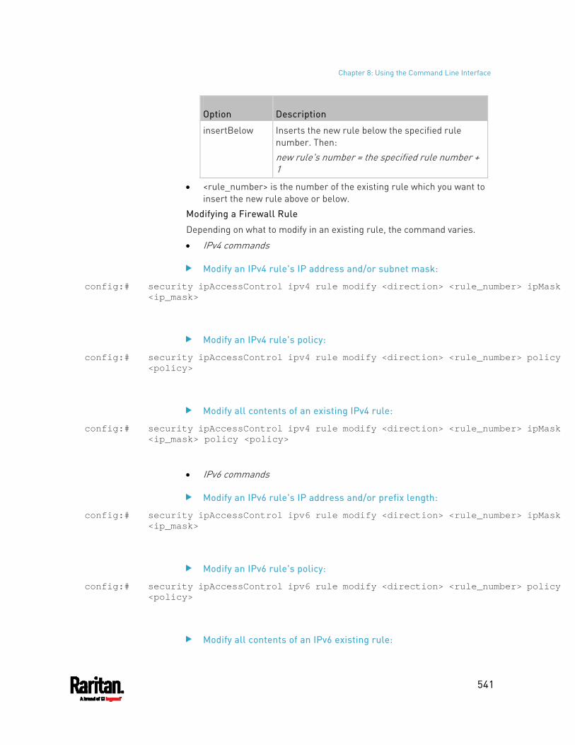
Chapter 8: Using the Command Line Interface
541
Option Description
insertBelow Inserts the new rule below the specified rule number. Then: new rule's number = the specified rule number + 1
<rule_number> is the number of the existing rule which you want to insert the new rule above or below.
Modifying a Firewall Rule
Depending on what to modify in an existing rule, the command varies.
IPv4 commands
Modify an IPv4 rule's IP address and/or subnet mask:
config:# security ipAccessControl ipv4 rule modify <direction> <rule_number> ipMask <ip_mask>
Modify an IPv4 rule's policy:
config:# security ipAccessControl ipv4 rule modify <direction> <rule_number> policy <policy>
Modify all contents of an existing IPv4 rule:
config:# security ipAccessControl ipv4 rule modify <direction> <rule_number> ipMask <ip_mask> policy <policy>
IPv6 commands
Modify an IPv6 rule's IP address and/or prefix length:
config:# security ipAccessControl ipv6 rule modify <direction> <rule_number> ipMask <ip_mask>
Modify an IPv6 rule's policy:
config:# security ipAccessControl ipv6 rule modify <direction> <rule_number> policy <policy>
Modify all contents of an IPv6 existing rule:
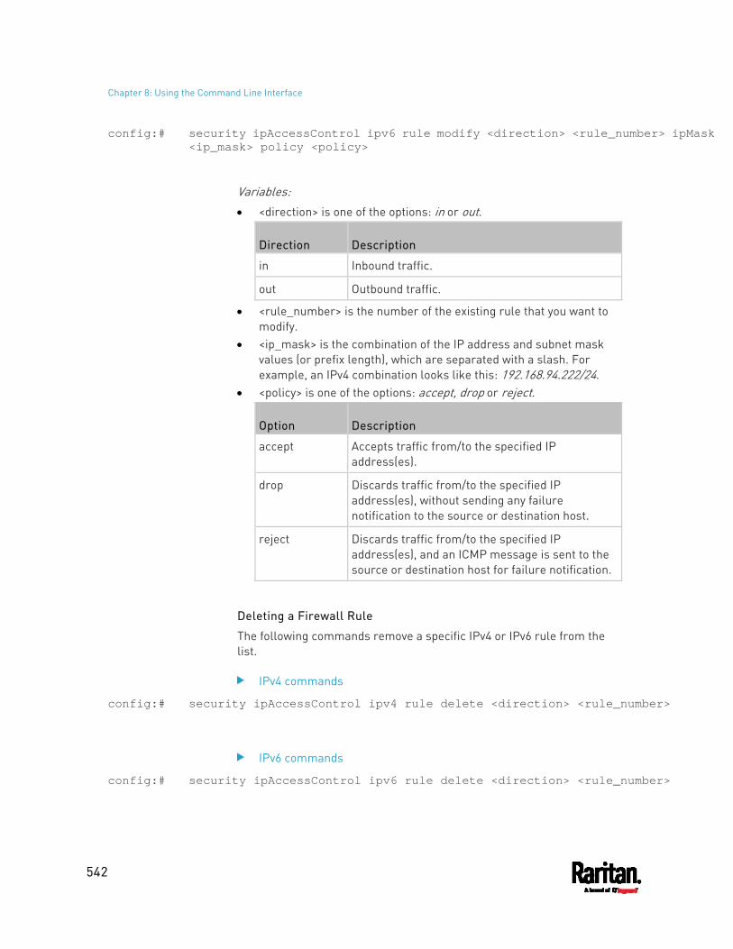
Chapter 8: Using the Command Line Interface
542
config:# security ipAccessControl ipv6 rule modify <direction> <rule_number> ipMask <ip_mask> policy <policy>
Variables: <direction> is one of the options: in or out.
Direction Description
in Inbound traffic.
out Outbound traffic.
<rule_number> is the number of the existing rule that you want to modify.
<ip_mask> is the combination of the IP address and subnet mask values (or prefix length), which are separated with a slash. For example, an IPv4 combination looks like this: 192.168.94.222/24.
<policy> is one of the options: accept, drop or reject.
Option Description
accept Accepts traffic from/to the specified IP address(es).
drop Discards traffic from/to the specified IP address(es), without sending any failure notification to the source or destination host.
reject Discards traffic from/to the specified IP address(es), and an ICMP message is sent to the source or destination host for failure notification.
Deleting a Firewall Rule
The following commands remove a specific IPv4 or IPv6 rule from the list.
IPv4 commands
config:# security ipAccessControl ipv4 rule delete <direction> <rule_number>
IPv6 commands
config:# security ipAccessControl ipv6 rule delete <direction> <rule_number>
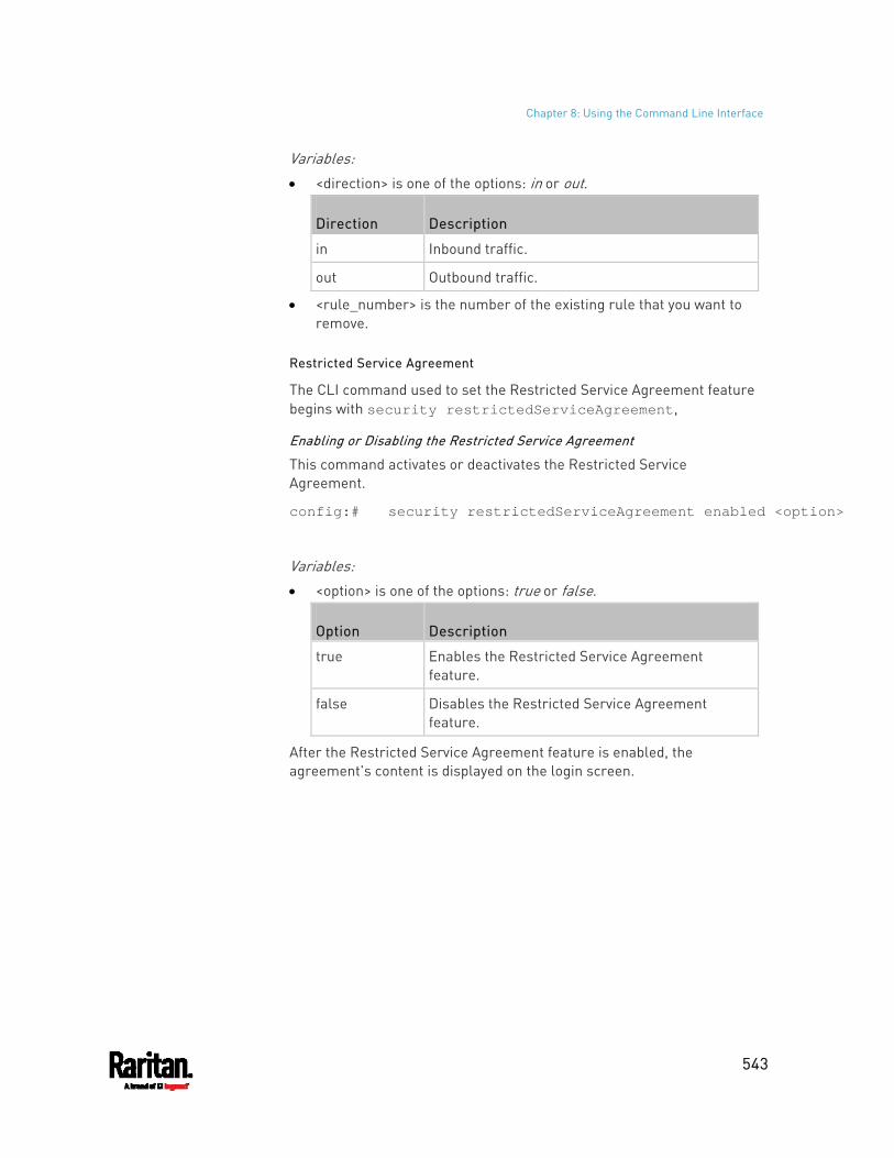
Chapter 8: Using the Command Line Interface
543
Variables: <direction> is one of the options: in or out.
Direction Description
in Inbound traffic.
out Outbound traffic.
<rule_number> is the number of the existing rule that you want to remove.
Restricted Service Agreement
The CLI command used to set the Restricted Service Agreement feature begins with security restrictedServiceAgreement,
Enabling or Disabling the Restricted Service Agreement
This command activates or deactivates the Restricted Service Agreement.
config:# security restrictedServiceAgreement enabled <option>
Variables: <option> is one of the options: true or false.
Option Description
true Enables the Restricted Service Agreement feature.
false Disables the Restricted Service Agreement feature.
After the Restricted Service Agreement feature is enabled, the agreement's content is displayed on the login screen.
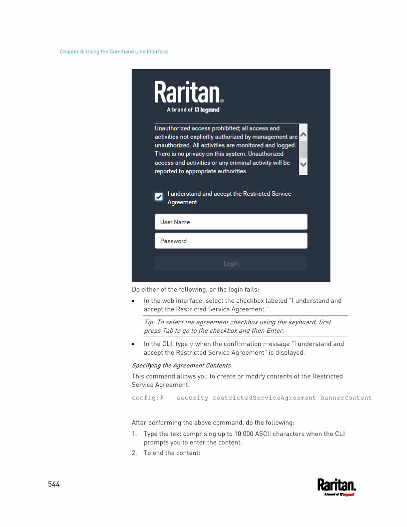
Chapter 8: Using the Command Line Interface
544
Do either of the following, or the login fails:
In the web interface, select the checkbox labeled "I understand and accept the Restricted Service Agreement."
Tip: To select the agreement checkbox using the keyboard, first press Tab to go to the checkbox and then Enter.
In the CLI, type y when the confirmation message "I understand and accept the Restricted Service Agreement" is displayed.
Specifying the Agreement Contents
This command allows you to create or modify contents of the Restricted Service Agreement.
config:# security restrictedServiceAgreement bannerContent
After performing the above command, do the following:
1. Type the text comprising up to 10,000 ASCII characters when the CLI prompts you to enter the content.
2. To end the content:
Chapter 8: Using the Command Line Interface
545
a. Press Enter.
b. Type --END-- to indicate the end of the content.
c. Press Enter again.
If the content is successfully entered, the CLI displays this message "Successfully entered Restricted Service Agreement" followed by the total number of entered characters in parentheses.
Note: The new content of Restricted Service Agreement is saved only after typing the apply command. See Quitting Configuration Mode (on page 501).
Example
The following example illustrates how to specify the content of the Restricted Service Agreement.
1. Type the following command and press Enter to start entering the content.
config:# security restrictedServiceAgreement bannerContent
2. Type the following content when the CLI prompts you to enter the content. IMPORTANT!! You are accessing a PDU. If you are not the system administrator, do NOT power off or power cycle any outlet without the permission of the system administrator.
3. Press Enter. 4. Type the following:
--END--
5. Press Enter again. 6. Verify that the message "Successfully entered Restricted Service
Agreement" is displayed, indicating that the content input is successful.
Login Limitation
The login limitation feature controls login-related limitations, such as password aging, simultaneous logins using the same user name, and the idle time permitted before forcing a user to log out.
A login limitation command begins with security loginLimits.
You can combine multiple commands to modify various login limitation parameters at a time. See Multi-Command Syntax (on page 625).
Chapter 8: Using the Command Line Interface
546
Single Login Limitation
This command enables or disables the single login feature, which controls whether multiple logins using the same login name simultaneously is permitted.
config:# security loginLimits singleLogin <option>
Variables: <option> is one of the options: enable or disable.
Option Description
enable Enables the single login feature.
disable Disables the single login feature.
Password Aging
This command enables or disables the password aging feature, which controls whether the password should be changed at a regular interval:
config:# security loginLimits passwordAging <option>
Variables: <option> is one of the options: enable or disable.
Option Description
enable Enables the password aging feature.
disable Disables the password aging feature.
Password Aging Interval
This command determines how often the password should be changed.
config:# security loginLimits passwordAgingInterval <value>
Variables: <value> is a numeric value in days set for the password aging
interval. The interval ranges from 7 to 365 days.
Chapter 8: Using the Command Line Interface
547
Idle Timeout
This command determines how long a user can remain idle before that user is forced to log out of the PX3 web interface or CLI.
config:# security loginLimits idleTimeout <value>
Variables: <value> is a numeric value in minutes set for the idle timeout. The
timeout ranges from 1 to 1440 minutes (24 hours).
User Blocking
There are different commands for changing different user blocking parameters. These commands begin with security userBlocking.
You can combine multiple commands to modify the user blocking parameters at a time. See Multi-Command Syntax (on page 625).
Determine the maximum number of failed logins before blocking a user:
config:# security userBlocking maximumNumberOfFailedLogins <value1>
Determine how long a user is blocked:
config:# security userBlocking blockTime <value2>
Variables: <value1> is an integer between 3 and 10, or unlimited, which sets no
limit on the maximum number of failed logins and thus disables the user blocking function.
<value2> is a numeric value ranging from 1 to 1440 minutes (one day), or infinite, which blocks the user all the time until the user is unblocked manually.
Strong Passwords
The strong password commands determine whether a strong password is required for login, and what a strong password should contain at least.
A strong password command begins with security strongPasswords.
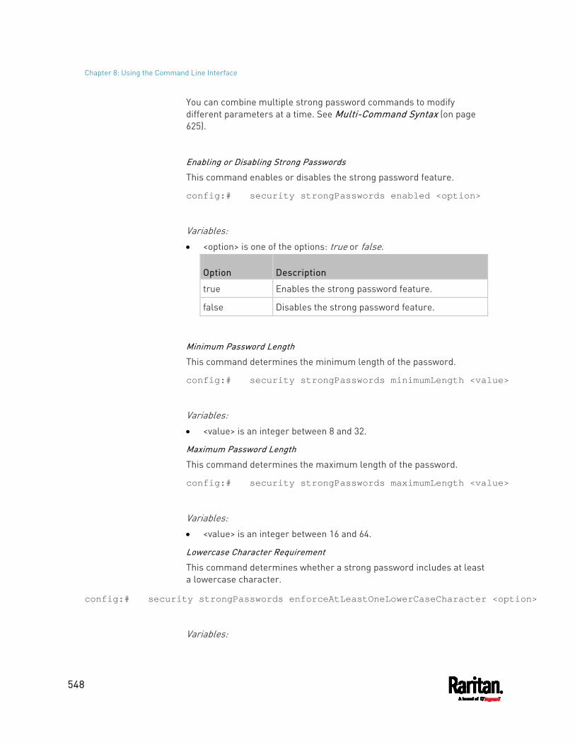
Chapter 8: Using the Command Line Interface
548
You can combine multiple strong password commands to modify different parameters at a time. See Multi-Command Syntax (on page 625).
Enabling or Disabling Strong Passwords
This command enables or disables the strong password feature.
config:# security strongPasswords enabled <option>
Variables: <option> is one of the options: true or false.
Option Description
true Enables the strong password feature.
false Disables the strong password feature.
Minimum Password Length
This command determines the minimum length of the password.
config:# security strongPasswords minimumLength <value>
Variables: <value> is an integer between 8 and 32.
Maximum Password Length
This command determines the maximum length of the password.
config:# security strongPasswords maximumLength <value>
Variables: <value> is an integer between 16 and 64.
Lowercase Character Requirement
This command determines whether a strong password includes at least a lowercase character.
config:# security strongPasswords enforceAtLeastOneLowerCaseCharacter <option>
Variables:
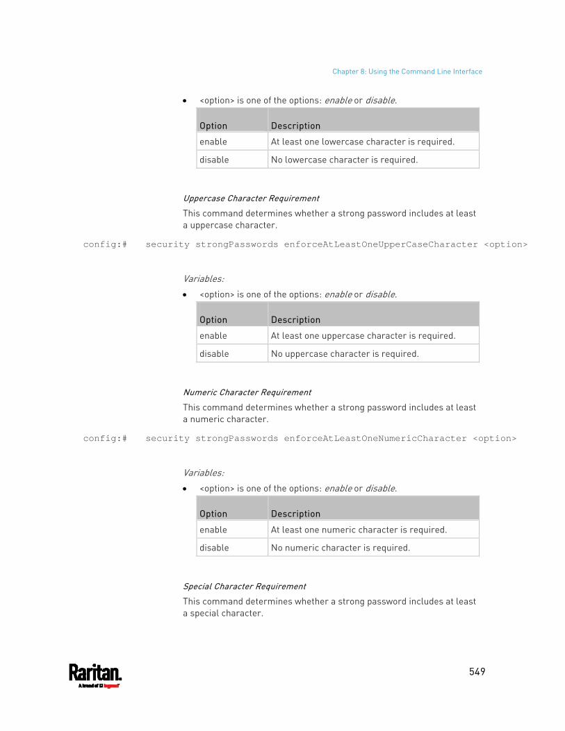
Chapter 8: Using the Command Line Interface
549
<option> is one of the options: enable or disable.
Option Description
enable At least one lowercase character is required.
disable No lowercase character is required.
Uppercase Character Requirement
This command determines whether a strong password includes at least a uppercase character.
config:# security strongPasswords enforceAtLeastOneUpperCaseCharacter <option>
Variables: <option> is one of the options: enable or disable.
Option Description
enable At least one uppercase character is required.
disable No uppercase character is required.
Numeric Character Requirement
This command determines whether a strong password includes at least a numeric character.
config:# security strongPasswords enforceAtLeastOneNumericCharacter <option>
Variables: <option> is one of the options: enable or disable.
Option Description
enable At least one numeric character is required.
disable No numeric character is required.
Special Character Requirement
This command determines whether a strong password includes at least a special character.
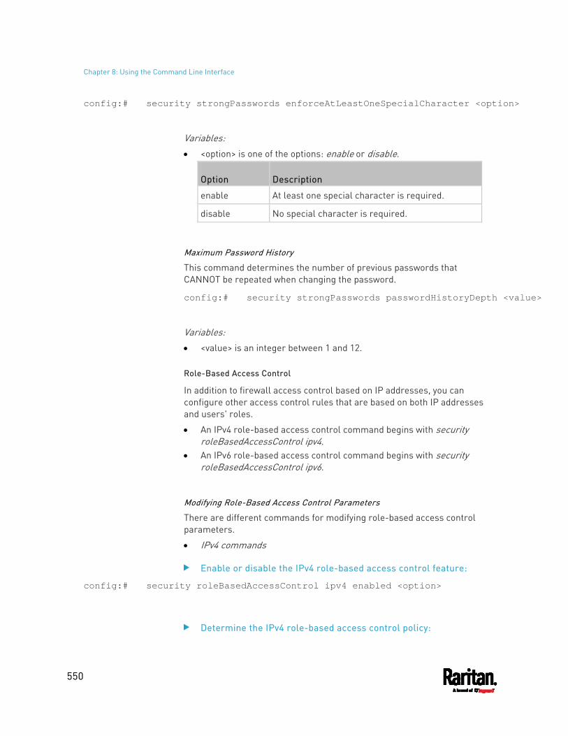
Chapter 8: Using the Command Line Interface
550
config:# security strongPasswords enforceAtLeastOneSpecialCharacter <option>
Variables: <option> is one of the options: enable or disable.
Option Description
enable At least one special character is required.
disable No special character is required.
Maximum Password History
This command determines the number of previous passwords that CANNOT be repeated when changing the password.
config:# security strongPasswords passwordHistoryDepth <value>
Variables: <value> is an integer between 1 and 12.
Role-Based Access Control
In addition to firewall access control based on IP addresses, you can configure other access control rules that are based on both IP addresses and users' roles.
An IPv4 role-based access control command begins with security roleBasedAccessControl ipv4.
An IPv6 role-based access control command begins with security roleBasedAccessControl ipv6.
Modifying Role-Based Access Control Parameters
There are different commands for modifying role-based access control parameters.
IPv4 commands
Enable or disable the IPv4 role-based access control feature:
config:# security roleBasedAccessControl ipv4 enabled <option>
Determine the IPv4 role-based access control policy:
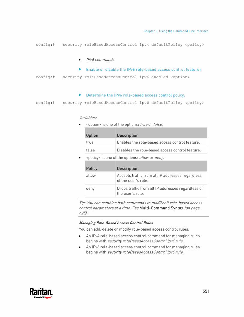
Chapter 8: Using the Command Line Interface
551
config:# security roleBasedAccessControl ipv4 defaultPolicy <policy>
IPv6 commands
Enable or disable the IPv6 role-based access control feature:
config:# security roleBasedAccessControl ipv6 enabled <option>
Determine the IPv6 role-based access control policy:
config:# security roleBasedAccessControl ipv6 defaultPolicy <policy>
Variables: <option> is one of the options: true or false.
Option Description
true Enables the role-based access control feature.
false Disables the role-based access control feature.
<policy> is one of the options: allow or deny.
Policy Description
allow Accepts traffic from all IP addresses regardless of the user's role.
deny Drops traffic from all IP addresses regardless of the user's role.
Tip: You can combine both commands to modify all role-based access control parameters at a time. See Multi-Command Syntax (on page 625).
Managing Role-Based Access Control Rules
You can add, delete or modify role-based access control rules.
An IPv4 role-based access control command for managing rules begins with security roleBasedAccessControl ipv4 rule.
An IPv6 role-based access control command for managing rules begins with security roleBasedAccessControl ipv6 rule.
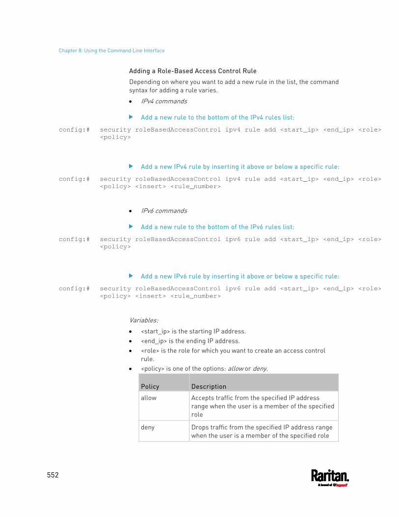
Chapter 8: Using the Command Line Interface
552
Adding a Role-Based Access Control Rule
Depending on where you want to add a new rule in the list, the command syntax for adding a rule varies.
IPv4 commands
Add a new rule to the bottom of the IPv4 rules list:
config:# security roleBasedAccessControl ipv4 rule add <start_ip> <end_ip> <role> <policy>
Add a new IPv4 rule by inserting it above or below a specific rule:
config:# security roleBasedAccessControl ipv4 rule add <start_ip> <end_ip> <role> <policy> <insert> <rule_number>
IPv6 commands
Add a new rule to the bottom of the IPv6 rules list:
config:# security roleBasedAccessControl ipv6 rule add <start_ip> <end_ip> <role> <policy>
Add a new IPv6 rule by inserting it above or below a specific rule:
config:# security roleBasedAccessControl ipv6 rule add <start_ip> <end_ip> <role> <policy> <insert> <rule_number>
Variables: <start_ip> is the starting IP address. <end_ip> is the ending IP address. <role> is the role for which you want to create an access control
rule. <policy> is one of the options: allow or deny.
Policy Description
allow Accepts traffic from the specified IP address range when the user is a member of the specified role
deny Drops traffic from the specified IP address range when the user is a member of the specified role
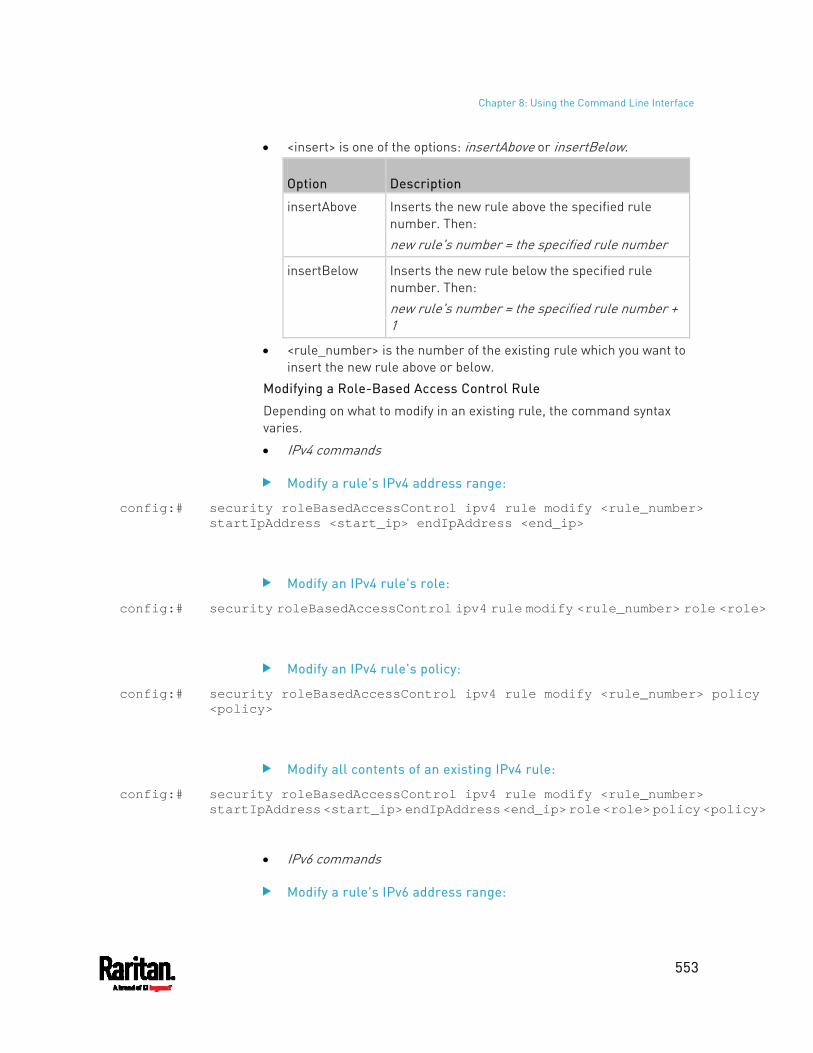
Chapter 8: Using the Command Line Interface
553
<insert> is one of the options: insertAbove or insertBelow.
Option Description
insertAbove Inserts the new rule above the specified rule number. Then: new rule's number = the specified rule number
insertBelow Inserts the new rule below the specified rule number. Then: new rule's number = the specified rule number + 1
<rule_number> is the number of the existing rule which you want to insert the new rule above or below.
Modifying a Role-Based Access Control Rule
Depending on what to modify in an existing rule, the command syntax varies.
IPv4 commands
Modify a rule's IPv4 address range:
config:# security roleBasedAccessControl ipv4 rule modify <rule_number> startIpAddress <start_ip> endIpAddress <end_ip>
Modify an IPv4 rule's role:
config:# security roleBasedAccessControl ipv4 rule modify <rule_number> role <role>
Modify an IPv4 rule's policy:
config:# security roleBasedAccessControl ipv4 rule modify <rule_number> policy <policy>
Modify all contents of an existing IPv4 rule:
config:# security roleBasedAccessControl ipv4 rule modify <rule_number> startIpAddress <start_ip> endIpAddress <end_ip> role <role> policy <policy>
IPv6 commands
Modify a rule's IPv6 address range:
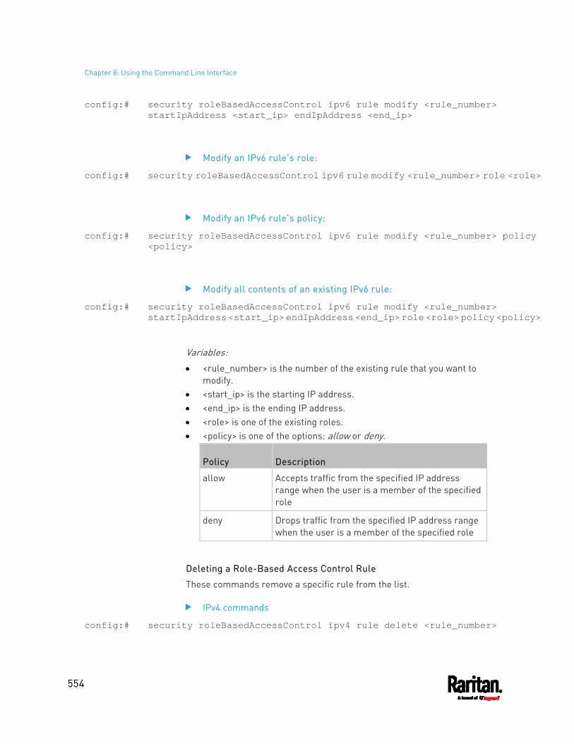
Chapter 8: Using the Command Line Interface
554
config:# security roleBasedAccessControl ipv6 rule modify <rule_number> startIpAddress <start_ip> endIpAddress <end_ip>
Modify an IPv6 rule's role:
config:# security roleBasedAccessControl ipv6 rule modify <rule_number> role <role>
Modify an IPv6 rule's policy:
config:# security roleBasedAccessControl ipv6 rule modify <rule_number> policy <policy>
Modify all contents of an existing IPv6 rule:
config:# security roleBasedAccessControl ipv6 rule modify <rule_number> startIpAddress <start_ip> endIpAddress <end_ip> role <role> policy <policy>
Variables: <rule_number> is the number of the existing rule that you want to
modify. <start_ip> is the starting IP address. <end_ip> is the ending IP address. <role> is one of the existing roles. <policy> is one of the options: allow or deny.
Policy Description
allow Accepts traffic from the specified IP address range when the user is a member of the specified role
deny Drops traffic from the specified IP address range when the user is a member of the specified role
Deleting a Role-Based Access Control Rule
These commands remove a specific rule from the list.
IPv4 commands
config:# security roleBasedAccessControl ipv4 rule delete <rule_number>
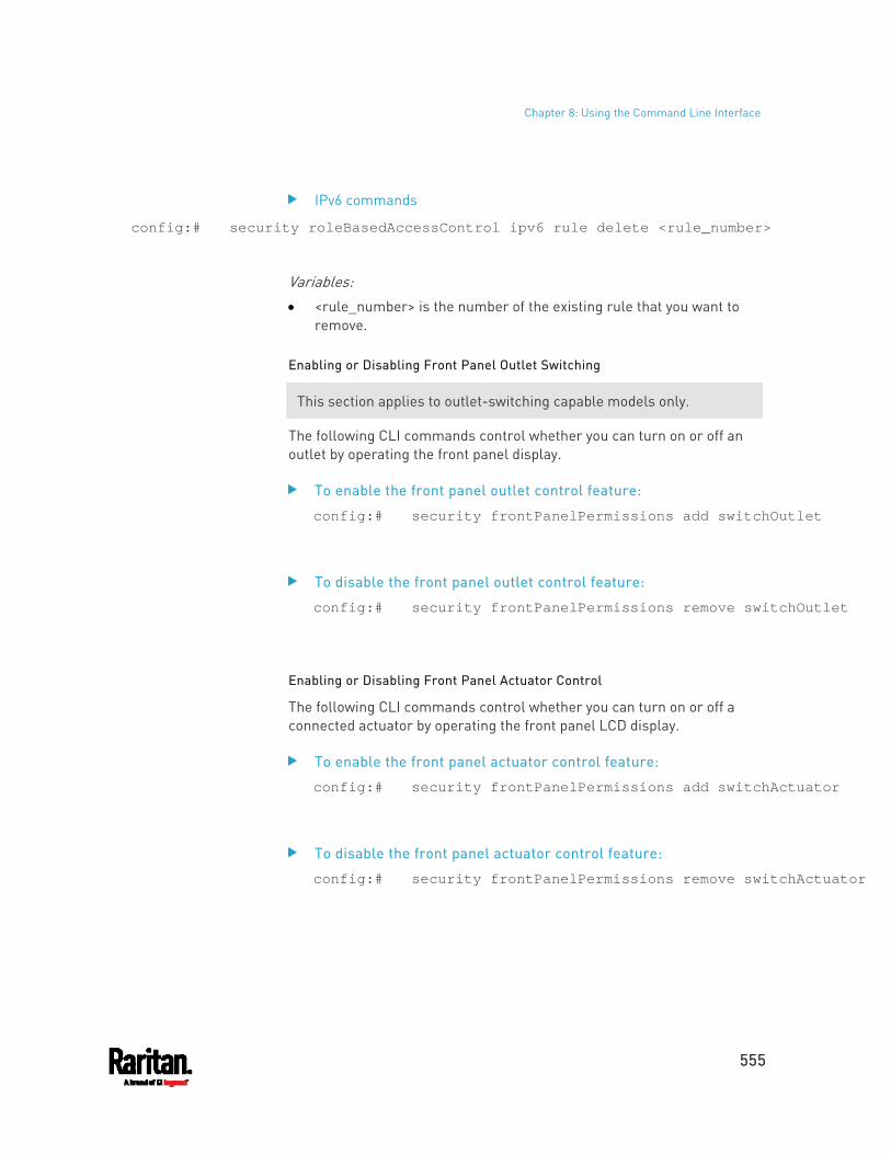
Chapter 8: Using the Command Line Interface
555
IPv6 commands
config:# security roleBasedAccessControl ipv6 rule delete <rule_number>
Variables: <rule_number> is the number of the existing rule that you want to
remove.
Enabling or Disabling Front Panel Outlet Switching
This section applies to outlet-switching capable models only.
The following CLI commands control whether you can turn on or off an outlet by operating the front panel display.
To enable the front panel outlet control feature:
config:# security frontPanelPermissions add switchOutlet
To disable the front panel outlet control feature:
config:# security frontPanelPermissions remove switchOutlet
Enabling or Disabling Front Panel Actuator Control
The following CLI commands control whether you can turn on or off a connected actuator by operating the front panel LCD display.
To enable the front panel actuator control feature:
config:# security frontPanelPermissions add switchActuator
To disable the front panel actuator control feature:
config:# security frontPanelPermissions remove switchActuator
Chapter 8: Using the Command Line Interface
556
Tip: If your PDU supports multiple front panel permissions, you can combine them into one command by adding a semicolon (;) between different permissions. For example, the following CLI command enables both front panel actuator control and outlet switching functions simultaneously. security frontPanelPermissions add switchActuator;switchOutlet
Examples
This section illustrates several security configuration examples.
Example 1 - IPv4 Firewall Control Configuration
The following command sets up two parameters of the IPv4 access control feature.
config:# security ipAccessControl ipv4 enabled true defaultPolicyIn accept defaultPolicyOut accept
Results: The IPv4 access control feature is enabled. The default policy for inbound traffic is set to "accept." The default policy for outbound traffic is set to "accept."
Example 2 - Adding an IPv4 Firewall Rule
The following command adds a new IPv4 access control rule and specifies its location in the list.
config:# security ipAccessControl ipv4 rule add 192.168.84.123/24 accept insertAbove 5
Results: A new IPv4 firewall control rule is added to accept all packets sent
from the IPv4 address 192.168.84.123. The newly-added rule is inserted above the 5th rule. That is, the new
rule becomes the 5th rule, and the original 5th rule becomes the 6th rule.
Chapter 8: Using the Command Line Interface
557
Example 3 - User Blocking
The following command sets up two user blocking parameters.
config:# security userBlocking maximumNumberOfFailedLogins 5 blockTime 30
Results: The maximum number of failed logins is set to 5. The user blocking time is set to 30 minutes.
Example 4 - Adding an IPv4 Role-based Access Control Rule
The following command creates a newIPv4 role-based access control rule and specifies its location in the list.
config:# security roleBasedAccessControl ipv4 rule add 192.168.78.50 192.168.90.100 admin deny insertAbove 3
Results: A new IPv4 role-based access control rule is added, dropping all
packets from any IPv4 address between 192.168.78.50 and 192.168.90.100 when the user is a member of the role "admin."
The newly-added IPv4 rule is inserted above the 3rd rule. That is, the new rule becomes the 3rd rule, and the original 3rd rule becomes the 4th rule.
Outlet Configuration Commands
An outlet configuration command begins with outlet. Such a command allows you to configure an individual outlet.
Changing the Outlet Name
This command names an outlet.
config:# outlet <n> name "<name>"
Variables:
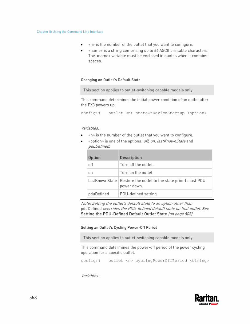
Chapter 8: Using the Command Line Interface
558
<n> is the number of the outlet that you want to configure. <name> is a string comprising up to 64 ASCII printable characters.
The <name> variable must be enclosed in quotes when it contains spaces.
Changing an Outlet's Default State
This section applies to outlet-switching capable models only.
This command determines the initial power condition of an outlet after the PX3 powers up.
config:# outlet <n> stateOnDeviceStartup <option>
Variables: <n> is the number of the outlet that you want to configure. <option> is one of the options: off, on, lastKnownState and
pduDefined.
Option Description
off Turn off the outlet.
on Turn on the outlet.
lastKnownState Restore the outlet to the state prior to last PDU power down.
pduDefined PDU-defined setting.
Note: Setting the outlet's default state to an option other than pduDefined overrides the PDU-defined default state on that outlet. See Setting the PDU-Defined Default Outlet State (on page 503).
Setting an Outlet's Cycling Power-Off Period
This section applies to outlet-switching capable models only.
This command determines the power-off period of the power cycling operation for a specific outlet.
config:# outlet <n> cyclingPowerOffPeriod <timing>
Variables:

Chapter 8: Using the Command Line Interface
559
<n> is the number of the outlet that you want to configure. <timing> is the time of the cycling power-off period in seconds,
which is an integer between 0 and 3600, or pduDefined for following the PDU-defined timing.
Note: This setting overrides the PDU-defined cycling power-off period on a particular outlet. See Setting the PDU-Defined Cycling Power-Off Period (on page 504).
Example - Outlet Naming
The following command assigns the name "Win XP" to outlet 8.
config:# outlet 8 name "Win XP"
Outlet Group Configuration Commands
An outlet group configuration command begins with outletgroup. Such a command allows you to configure or operate an outlet group.
Creating an Outlet Group
This command creates a new outlet group.
config:# outletgroup add "<name>" <members>
Variables: <name> is a string comprising up to 64 ASCII printable characters.
The <name> variable must be enclosed in quotes when it contains spaces.
Tip: PX3 allows you to assign the same name to diverse outlet groups. If this really occurs, you still can identify different groups through their unique index numbers.
<members> is one or multiple member outlets' index numbers separated with commas. If the member outlets are consecutive outlets, you can type a hyphen between the initial and the final index number instead of using commas. For example, to assign outlets 3, 4, 5, 8 and 10 to the outlet group named "servers", you have two choices -- either use a hyphen for consecutive outlets 3 to 5, or use commas for all of member outlets: outletgroup add servers 3-5,8,10
-- OR --
Chapter 8: Using the Command Line Interface
560
outletgroup add servers 3,4,5,8,10
Managing an Outlet Group
You can modify an outlet group's name and member outlets, or simply remove any existing outlet group.
You can modify both the name and members of an outlet group at a time by combining multiple commands. See Multi-Command Syntax (on page 625).
Modify an outlet group's name:
config:# outletgroup modify <ID> name "<name>"
Modify an outlet group's member outlets:
config:# outletgroup modify <ID> members <members>
Delete an outlet group:
config:# outletgroup delete <ID>
Variables: <ID> is an outlet group's index number. <name> is a string comprising up to 64 ASCII printable characters.
The <name> variable must be enclosed in quotes when it contains spaces.
<members> is one or multiple member outlets' index numbers separated with commas. If the member outlets are consecutive outlets, you can type a hyphen between the initial and the final index number instead of using commas. For example, to assign outlets 3, 4, 5, 8 and 10 to the outlet group named "servers", you have two choices -- either use a hyphen for consecutive outlets 3 to 5, or use commas for all of member outlets: In the following examples, it is assumed that the "servers" outlet group's index number is 2. outletgroup modify 2 members 3-5,8,10
-- OR -- outletgroup modify 2 members 3,4,5,8,10
Chapter 8: Using the Command Line Interface
561
Powering On/Off/Cycle Outlet Groups
This section applies to outlet-switching capable models only.
Power on one outlet group:
# power outletgroup <ID> on
Power off one outlet group:
# power outletgroup <ID> off
Power cycle one outlet group:
# power outletgroup <ID> cycle
To quicken the operation, you can add the parameter "/y" to the end of the command, which confirms the operation.
For example:
# power outletgroup <ID> off /y
If you entered the command without "/y", a message appears, prompting you to confirm the operation. Then:
Type y to confirm the operation, OR
Type n to abort the operation
Variables: <ID> is an outlet group's index number.
Inlet Configuration Commands
An inlet configuration command begins with inlet. You can configure an inlet by using the inlet configuration command.
Changing the Inlet Name
This command syntax names an inlet.
config:# inlet <n> name "<name>"
Chapter 8: Using the Command Line Interface
562
Variables: <n> is the number of the inlet that you want to configure. For a
single-inlet PDU, <n> is always 1. The value is an integer between 1 and 50.
<name> is a string comprising up to 64 ASCII printable characters. The <name> variable must be enclosed in quotes when it contains spaces.
Enabling or Disabling an Inlet (for Multi-Inlet PDUs)
Enabling or disabling an inlet takes effect on a multi-inlet PDU only.
This command enables or disables an inlet.
config:# inlet <n> enabled <option>
Variables: <n> is the number of the inlet that you want to configure. For a
single-inlet PDU, <n> is always 1. The value is an integer between 1 and 50.
<option> is one of the options: true or false.
Option Description
true The specified inlet is enabled.
false The specified inlet is disabled.
Note: If performing this command causes all inlets to be disabled, a warning message appears, prompting you to confirm. When this occurs, press y to confirm or n to cancel the operation.
Example - Inlet Naming
The following command assigns the name "AC source" to the inlet 1. If your PX3 contains multiple inlets, this command names the 1st inlet.
config:# inlet 1 name "AC source"
Chapter 8: Using the Command Line Interface
563
Overcurrent Protector Configuration Commands
An overcurrent protector configuration command begins with ocp. The command configures an individual circuit breaker or fuse which protects outlets.
Changing the Overcurrent Protector Name
This command names a circuit breaker or a fuse which protects outlets on your PX3.
config:# ocp <n> name "<name>"
Variables: <n> is the number of the overcurrent protector that you want to
configure. The value is an integer between 1 and 50. <name> is a string comprising up to 64 ASCII printable characters.
The <name> variable must be enclosed in quotes when it contains spaces.
Example - OCP Naming
The command assigns the name "Email servers CB" to the overcurrent protector labeled 2.
config:# ocp 2 name "Email servers CB"
User Configuration Commands
Most user configuration commands begin with user except for the password change command.
Creating a User Profile
This command creates a new user profile.
config:# user create <name> <option> <roles>
After performing the user creation command, the PX3 prompts you to assign a password to the newly-created user. Then:
1. Type the password and press Enter.
Chapter 8: Using the Command Line Interface
564
2. Re-type the same password for confirmation and press Enter.
Variables:
<name> is a string comprising up to 32 ASCII printable characters. The <name> variable CANNOT contain spaces.
<option> is one of the options: enable or disable.
Option Description
enable Enables the newly-created user profile.
disable Disables the newly-created user profile.
<roles> is a role or a list of comma-separated roles assigned to the specified user profile.
Modifying a User Profile
A user profile contains various parameters that you can modify.
Tip: You can combine all commands to modify the parameters of a specific user profile at a time. See Multi-Command Syntax (on page 625).
Changing a User's Password
This command allows you to change an existing user's password if you have the Administrator Privileges.
config:# user modify <name> password
After performing the above command, PX3 prompts you to enter a new password. Then:
1. Type a new password and press Enter. 2. Re-type the new password for confirmation and press Enter.
Variables:
<name> is the name of the user whose settings you want to change.
Example
The following procedure illustrates how to change the password of the user "May."
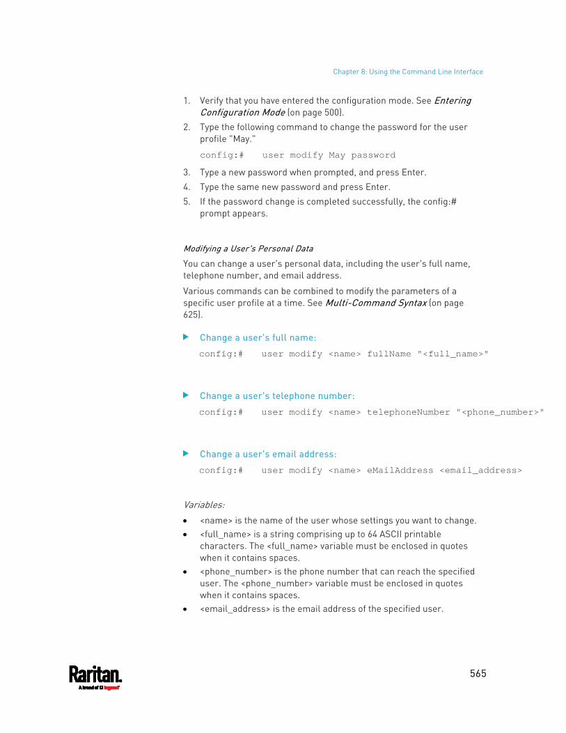
Chapter 8: Using the Command Line Interface
565
1. Verify that you have entered the configuration mode. See Entering Configuration Mode (on page 500).
2. Type the following command to change the password for the user profile "May."
config:# user modify May password
3. Type a new password when prompted, and press Enter. 4. Type the same new password and press Enter. 5. If the password change is completed successfully, the config:#
prompt appears.
Modifying a User's Personal Data
You can change a user's personal data, including the user's full name, telephone number, and email address.
Various commands can be combined to modify the parameters of a specific user profile at a time. See Multi-Command Syntax (on page 625).
Change a user's full name:
config:# user modify <name> fullName "<full_name>"
Change a user's telephone number:
config:# user modify <name> telephoneNumber "<phone_number>"
Change a user's email address:
config:# user modify <name> eMailAddress <email_address>
Variables:
<name> is the name of the user whose settings you want to change. <full_name> is a string comprising up to 64 ASCII printable
characters. The <full_name> variable must be enclosed in quotes when it contains spaces.
<phone_number> is the phone number that can reach the specified user. The <phone_number> variable must be enclosed in quotes when it contains spaces.
<email_address> is the email address of the specified user.
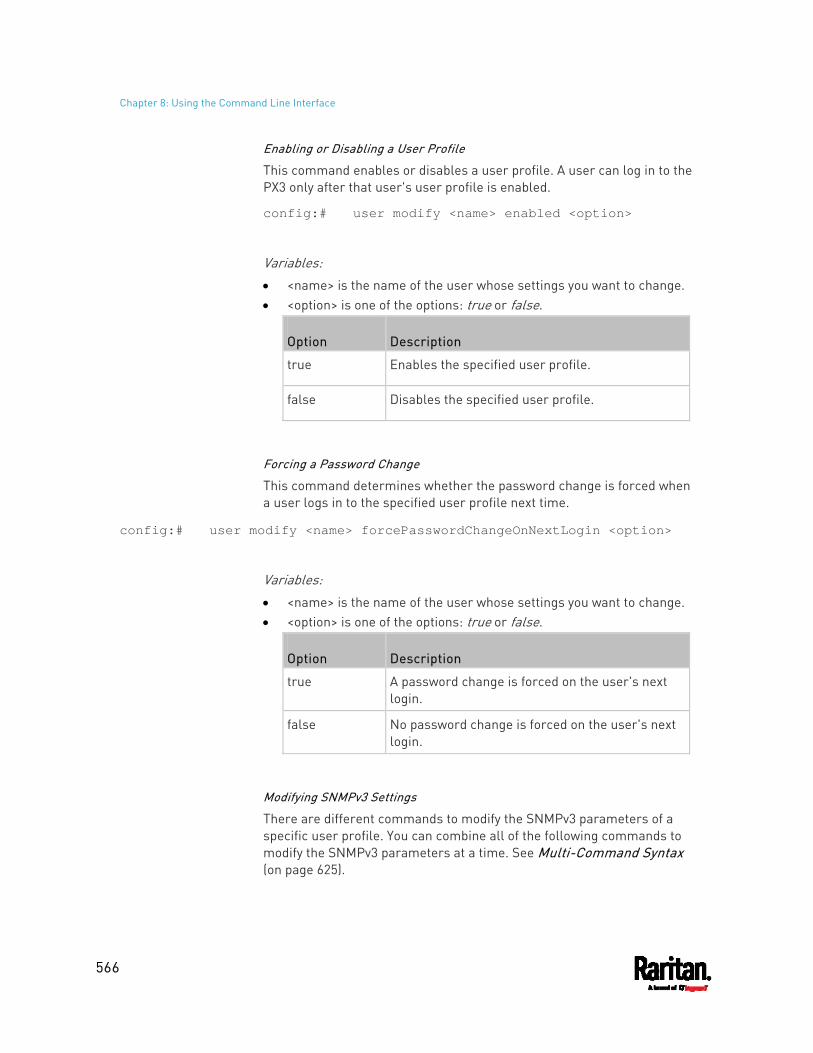
Chapter 8: Using the Command Line Interface
566
Enabling or Disabling a User Profile
This command enables or disables a user profile. A user can log in to the PX3 only after that user's user profile is enabled.
config:# user modify <name> enabled <option>
Variables:
<name> is the name of the user whose settings you want to change. <option> is one of the options: true or false.
Option Description
true Enables the specified user profile.
false Disables the specified user profile.
Forcing a Password Change
This command determines whether the password change is forced when a user logs in to the specified user profile next time.
config:# user modify <name> forcePasswordChangeOnNextLogin <option>
Variables:
<name> is the name of the user whose settings you want to change. <option> is one of the options: true or false.
Option Description
true A password change is forced on the user's next login.
false No password change is forced on the user's next login.
Modifying SNMPv3 Settings
There are different commands to modify the SNMPv3 parameters of a specific user profile. You can combine all of the following commands to modify the SNMPv3 parameters at a time. See Multi-Command Syntax (on page 625).
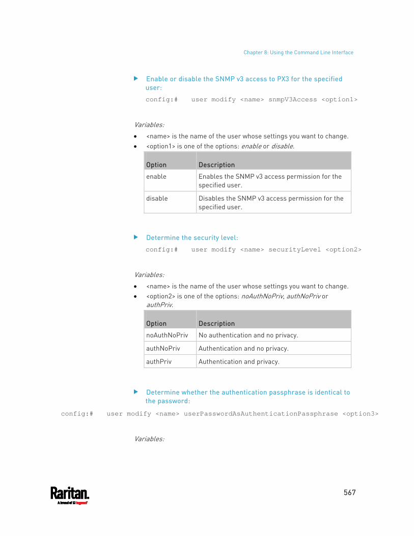
Chapter 8: Using the Command Line Interface
567
Enable or disable the SNMP v3 access to PX3 for the specified user:
config:# user modify <name> snmpV3Access <option1>
Variables:
<name> is the name of the user whose settings you want to change. <option1> is one of the options: enable or disable.
Option Description
enable Enables the SNMP v3 access permission for the specified user.
disable Disables the SNMP v3 access permission for the specified user.
Determine the security level:
config:# user modify <name> securityLevel <option2>
Variables:
<name> is the name of the user whose settings you want to change. <option2> is one of the options: noAuthNoPriv, authNoPriv or
authPriv.
Option Description
noAuthNoPriv No authentication and no privacy.
authNoPriv Authentication and no privacy.
authPriv Authentication and privacy.
Determine whether the authentication passphrase is identical to the password:
config:# user modify <name> userPasswordAsAuthenticationPassphrase <option3>
Variables:
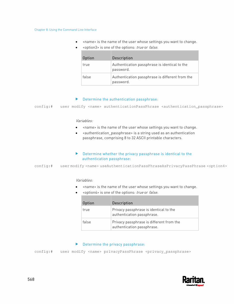
Chapter 8: Using the Command Line Interface
568
<name> is the name of the user whose settings you want to change. <option3> is one of the options: true or false.
Option Description
true Authentication passphrase is identical to the password.
false Authentication passphrase is different from the password.
Determine the authentication passphrase:
config:# user modify <name> authenticationPassPhrase <authentication_passphrase>
Variables:
<name> is the name of the user whose settings you want to change. <authentication_passphrase> is a string used as an authentication
passphrase, comprising 8 to 32 ASCII printable characters.
Determine whether the privacy passphrase is identical to the authentication passphrase:
config:# user modify <name> useAuthenticationPassPhraseAsPrivacyPassPhrase <option4>
Variables:
<name> is the name of the user whose settings you want to change. <option4> is one of the options: true or false.
Option Description
true Privacy passphrase is identical to the authentication passphrase.
false Privacy passphrase is different from the authentication passphrase.
Determine the privacy passphrase:
config:# user modify <name> privacyPassPhrase <privacy_passphrase>
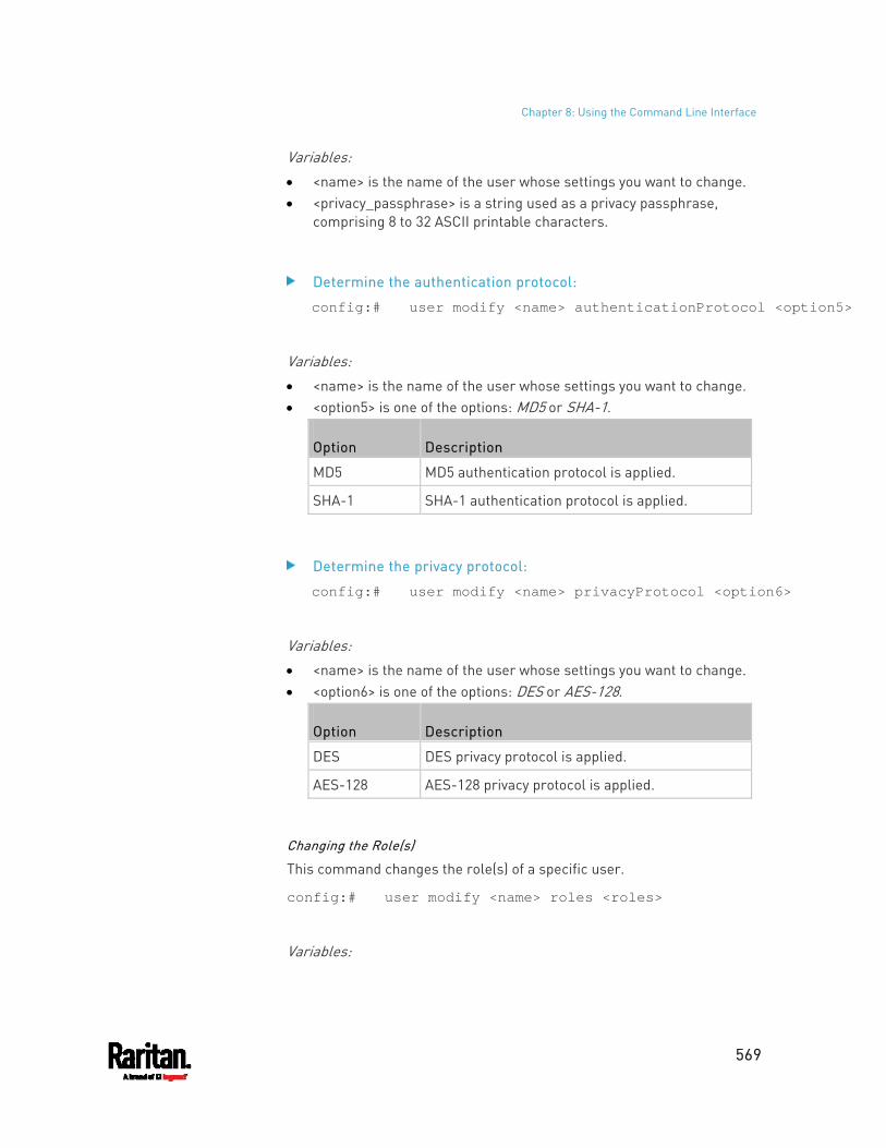
Chapter 8: Using the Command Line Interface
569
Variables:
<name> is the name of the user whose settings you want to change. <privacy_passphrase> is a string used as a privacy passphrase,
comprising 8 to 32 ASCII printable characters.
Determine the authentication protocol:
config:# user modify <name> authenticationProtocol <option5>
Variables:
<name> is the name of the user whose settings you want to change. <option5> is one of the options: MD5 or SHA-1.
Option Description
MD5 MD5 authentication protocol is applied.
SHA-1 SHA-1 authentication protocol is applied.
Determine the privacy protocol:
config:# user modify <name> privacyProtocol <option6>
Variables:
<name> is the name of the user whose settings you want to change. <option6> is one of the options: DES or AES-128.
Option Description
DES DES privacy protocol is applied.
AES-128 AES-128 privacy protocol is applied.
Changing the Role(s)
This command changes the role(s) of a specific user.
config:# user modify <name> roles <roles>
Variables:
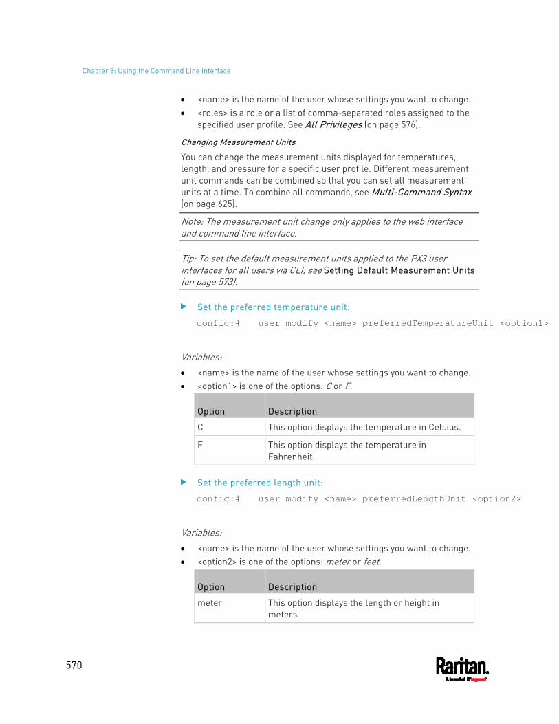
Chapter 8: Using the Command Line Interface
570
<name> is the name of the user whose settings you want to change. <roles> is a role or a list of comma-separated roles assigned to the
specified user profile. See All Privileges (on page 576).
Changing Measurement Units
You can change the measurement units displayed for temperatures, length, and pressure for a specific user profile. Different measurement unit commands can be combined so that you can set all measurement units at a time. To combine all commands, see Multi-Command Syntax (on page 625).
Note: The measurement unit change only applies to the web interface and command line interface.
Tip: To set the default measurement units applied to the PX3 user interfaces for all users via CLI, see Setting Default Measurement Units (on page 573).
Set the preferred temperature unit:
config:# user modify <name> preferredTemperatureUnit <option1>
Variables:
<name> is the name of the user whose settings you want to change. <option1> is one of the options: C or F.
Option Description
C This option displays the temperature in Celsius.
F This option displays the temperature in Fahrenheit.
Set the preferred length unit:
config:# user modify <name> preferredLengthUnit <option2>
Variables:
<name> is the name of the user whose settings you want to change. <option2> is one of the options: meter or feet.
Option Description
meter This option displays the length or height in meters.
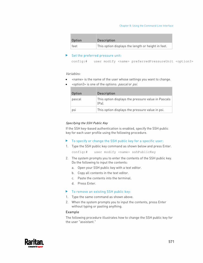
Chapter 8: Using the Command Line Interface
571
Option Description
feet This option displays the length or height in feet.
Set the preferred pressure unit:
config:# user modify <name> preferredPressureUnit <option3>
Variables:
<name> is the name of the user whose settings you want to change. <option3> is one of the options: pascal or psi.
Option Description
pascal This option displays the pressure value in Pascals (Pa).
psi This option displays the pressure value in psi.
Specifying the SSH Public Key
If the SSH key-based authentication is enabled, specify the SSH public key for each user profile using the following procedure.
To specify or change the SSH public key for a specific user: 1. Type the SSH public key command as shown below and press Enter.
config:# user modify <name> sshPublicKey
2. The system prompts you to enter the contents of the SSH public key. Do the following to input the contents: a. Open your SSH public key with a text editor. b. Copy all contents in the text editor. c. Paste the contents into the terminal. d. Press Enter.
To remove an existing SSH public key: 1. Type the same command as shown above. 2. When the system prompts you to input the contents, press Enter
without typing or pasting anything.
Example
The following procedure illustrates how to change the SSH public key for the user "assistant."
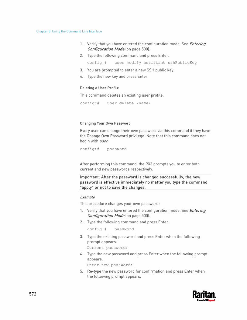
Chapter 8: Using the Command Line Interface
572
1. Verify that you have entered the configuration mode. See Entering Configuration Mode (on page 500).
2. Type the following command and press Enter.
config:# user modify assistant sshPublicKey
3. You are prompted to enter a new SSH public key. 4. Type the new key and press Enter.
Deleting a User Profile
This command deletes an existing user profile.
config:# user delete <name>
Changing Your Own Password
Every user can change their own password via this command if they have the Change Own Password privilege. Note that this command does not begin with user.
config:# password
After performing this command, the PX3 prompts you to enter both current and new passwords respectively.
Important: After the password is changed successfully, the new password is effective immediately no matter you type the command "apply" or not to save the changes.
Example
This procedure changes your own password:
1. Verify that you have entered the configuration mode. See Entering Configuration Mode (on page 500).
2. Type the following command and press Enter.
config:# password
3. Type the existing password and press Enter when the following prompt appears. Current password:
4. Type the new password and press Enter when the following prompt appears. Enter new password:
5. Re-type the new password for confirmation and press Enter when the following prompt appears.
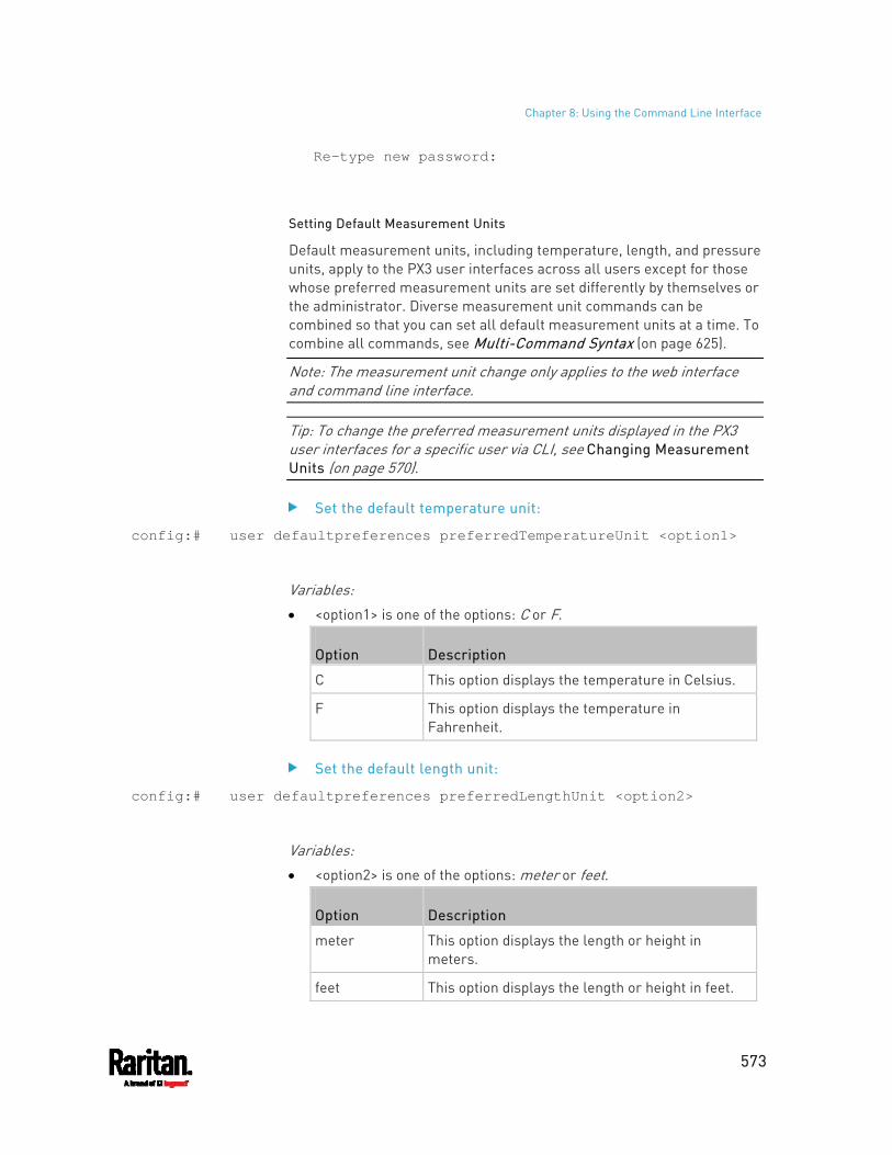
Chapter 8: Using the Command Line Interface
573
Re-type new password:
Setting Default Measurement Units
Default measurement units, including temperature, length, and pressure units, apply to the PX3 user interfaces across all users except for those whose preferred measurement units are set differently by themselves or the administrator. Diverse measurement unit commands can be combined so that you can set all default measurement units at a time. To combine all commands, see Multi-Command Syntax (on page 625).
Note: The measurement unit change only applies to the web interface and command line interface.
Tip: To change the preferred measurement units displayed in the PX3 user interfaces for a specific user via CLI, see Changing Measurement Units (on page 570).
Set the default temperature unit:
config:# user defaultpreferences preferredTemperatureUnit <option1>
Variables:
<option1> is one of the options: C or F.
Option Description
C This option displays the temperature in Celsius.
F This option displays the temperature in Fahrenheit.
Set the default length unit:
config:# user defaultpreferences preferredLengthUnit <option2>
Variables:
<option2> is one of the options: meter or feet.
Option Description
meter This option displays the length or height in meters.
feet This option displays the length or height in feet.
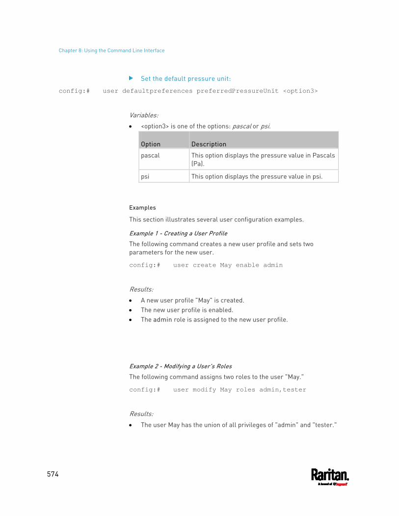
Chapter 8: Using the Command Line Interface
574
Set the default pressure unit:
config:# user defaultpreferences preferredPressureUnit <option3>
Variables:
<option3> is one of the options: pascal or psi.
Option Description
pascal This option displays the pressure value in Pascals (Pa).
psi This option displays the pressure value in psi.
Examples
This section illustrates several user configuration examples.
Example 1 - Creating a User Profile
The following command creates a new user profile and sets two parameters for the new user.
config:# user create May enable admin
Results: A new user profile "May" is created. The new user profile is enabled. The admin role is assigned to the new user profile.
Example 2 - Modifying a User's Roles
The following command assigns two roles to the user "May."
config:# user modify May roles admin,tester
Results: The user May has the union of all privileges of "admin" and "tester."
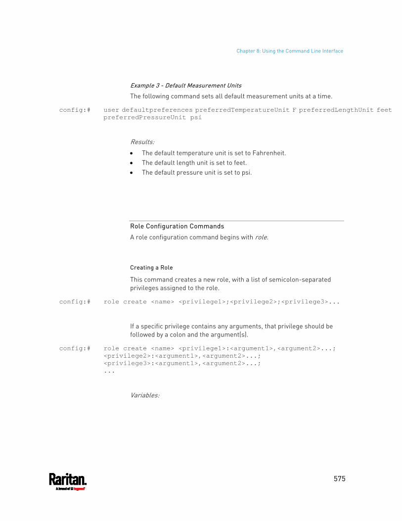
Chapter 8: Using the Command Line Interface
575
Example 3 - Default Measurement Units
The following command sets all default measurement units at a time.
config:# user defaultpreferences preferredTemperatureUnit F preferredLengthUnit feet preferredPressureUnit psi
Results: The default temperature unit is set to Fahrenheit. The default length unit is set to feet. The default pressure unit is set to psi.
Role Configuration Commands
A role configuration command begins with role.
Creating a Role
This command creates a new role, with a list of semicolon-separated privileges assigned to the role.
config:# role create <name> <privilege1>;<privilege2>;<privilege3>...
If a specific privilege contains any arguments, that privilege should be followed by a colon and the argument(s).
config:# role create <name> <privilege1>:<argument1>,<argument2>...; <privilege2>:<argument1>,<argument2>...; <privilege3>:<argument1>,<argument2>...; ...
Variables:

Chapter 8: Using the Command Line Interface
576
<name> is a string comprising up to 32 ASCII printable characters. <privilege1>, <privilege2>, <privilege3> and the like are names of the
privileges assigned to the role. Separate each privilege with a semi-colon. See All Privileges (on page 576).
<argument1>, <argument2> and the like are arguments set for a particular privilege. Separate a privilege and its argument(s) with a colon, and separate arguments with a comma if there are more than one argument for a privilege.
All Privileges
This table lists all privileges. Note that available privileges vary according to the model you purchased. For example, a PDU without the outlet switching function does not have the privilege "switchOutlet."
Privilege Description
acknowledgeAlarms Acknowledge Alarms
adminPrivilege Administrator Privileges
changeAssetStripConfiguration Change Asset Strip Configuration
changeAuthSettings Change Authentication Settings
changeDataTimeSettings Change Date/Time Settings
changeExternalSensorsConfiguration Change Peripheral Device Configuration
changeLhxConfiguration Change LHX/SHX Configuration
changeModemConfiguration Change Modem Configuration
changeNetworkSettings Change Network Settings
changePassword Change Own Password
changePduConfiguration Change Pdu, Inlet, Outlet & Overcurrent Protector Configuration
changeSecuritySettings Change Security Settings
changeSnmpSettings Change SNMP Settings
changeUserSettings Change Local User Management
changeWebcamSettings Change Webcam Configuration
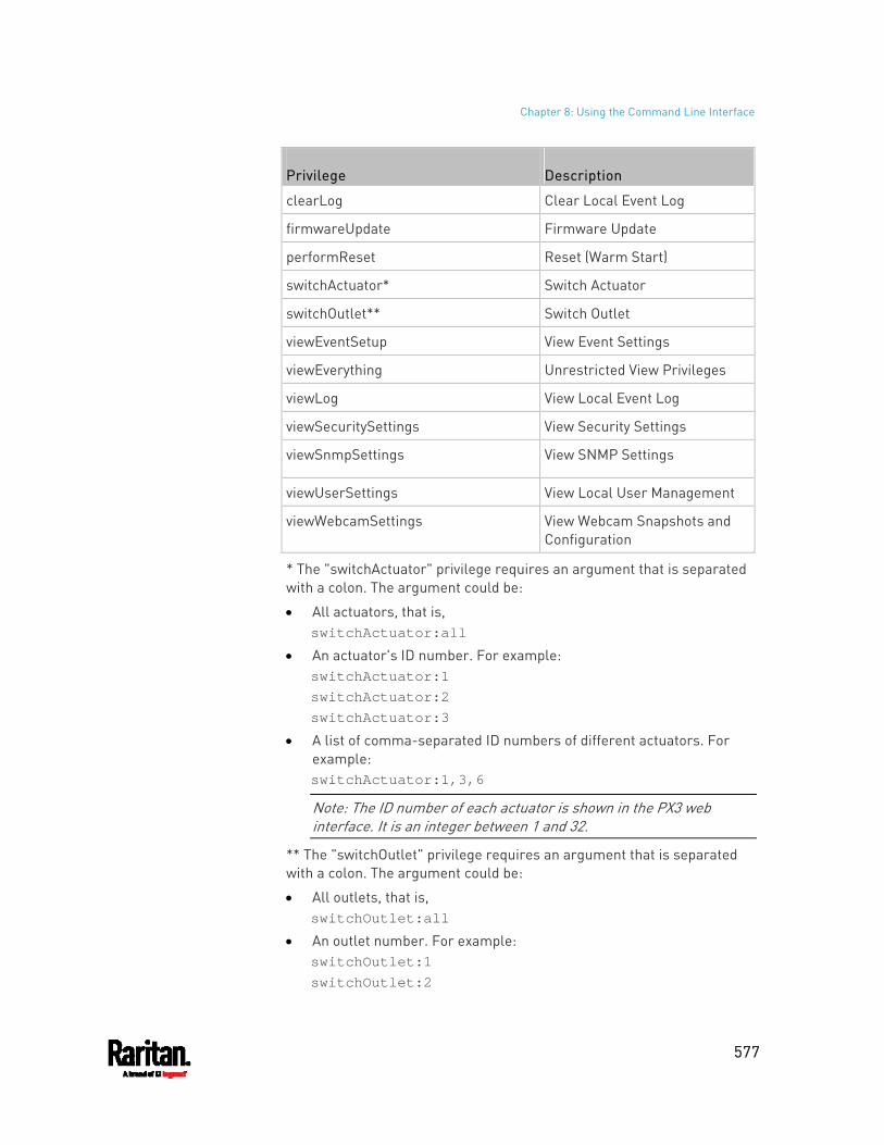
Chapter 8: Using the Command Line Interface
577
Privilege Description
clearLog Clear Local Event Log
firmwareUpdate Firmware Update
performReset Reset (Warm Start)
switchActuator* Switch Actuator
switchOutlet** Switch Outlet
viewEventSetup View Event Settings
viewEverything Unrestricted View Privileges
viewLog View Local Event Log
viewSecuritySettings View Security Settings
viewSnmpSettings View SNMP Settings
viewUserSettings View Local User Management
viewWebcamSettings View Webcam Snapshots and Configuration
* The "switchActuator" privilege requires an argument that is separated with a colon. The argument could be:
All actuators, that is, switchActuator:all
An actuator's ID number. For example: switchActuator:1 switchActuator:2 switchActuator:3
A list of comma-separated ID numbers of different actuators. For example: switchActuator:1,3,6
Note: The ID number of each actuator is shown in the PX3 web interface. It is an integer between 1 and 32.
** The "switchOutlet" privilege requires an argument that is separated with a colon. The argument could be:
All outlets, that is, switchOutlet:all
An outlet number. For example: switchOutlet:1 switchOutlet:2
Chapter 8: Using the Command Line Interface
578
switchOutlet:3
A list of comma-separated outlets. For example: switchOutlet:1,3,5,7,8,9
Modifying a Role
You can modify diverse parameters of an existing role, including its privileges.
Modify a role's description:
config:# role modify <name> description "<description>"
Variables:
<name> is a string comprising up to 32 ASCII printable characters. <description> is a description comprising alphanumeric characters.
The <description> variable must be enclosed in quotes when it contains spaces.
Add more privileges to a specific role:
config:# role modify <name> addPrivileges <privilege1>;<privilege2>;<privilege3>...
If a specific privilege contains any arguments, add a colon and the argument(s) after that privilege.
config:# role modify <name> addPrivileges <privilege1>:<argument1>,<argument2>...; <privilege2>:<argument1>,<argument2>...; <privilege3>:<argument1>,<argument2>...; ...
Variables:
<name> is a string comprising up to 32 ASCII printable characters. <privilege1>, <privilege2>, <privilege3> and the like are names of the
privileges assigned to the role. Separate each privilege with a semi-colon. See All Privileges (on page 576).
<argument1>, <argument2> and the like are arguments set for a particular privilege. Separate a privilege and its argument(s) with a colon, and separate arguments with a comma if there are more than one argument for a privilege.
Chapter 8: Using the Command Line Interface
579
Remove specific privileges from a role:
config:# role modify <name> removePrivileges <privilege1>;<privilege2>;<privilege3>...
If a specific privilege contains any arguments, add a colon and the argument(s) after that privilege.
config:# role modify <name> removePrivileges <privilege1>:<argument1>,<argument2>...; <privilege2>:<argument1>,<argument2>...; <privilege3>:<argument1>,<argument2>...; ...
Note: When removing privileges from a role, make sure the specified privileges and arguments (if any) exactly match those assigned to the role. Otherwise, the command fails to remove specified privileges that are not available.
Variables:
<name> is a string comprising up to 32 ASCII printable characters. <privilege1>, <privilege2>, <privilege3> and the like are names of the
privileges assigned to the role. Separate each privilege with a semi-colon. See All Privileges (on page 576).
<argument1>, <argument2> and the like are arguments set for a particular privilege. Separate a privilege and its argument(s) with a colon, and separate arguments with a comma if there are more than one argument for a privilege.
Deleting a Role
This command deletes an existing role.
config:# role delete <name>
Example - Creating a Role
The following command creates a new role and assigns privileges to the role.
config:# role create tester firmwareUpdate;viewEventSetup
Results:
Chapter 8: Using the Command Line Interface
580
A new role "tester" is created. Two privileges are assigned to the role: firmwareUpdate (Firmware
Update) and viewEventSetup (View Event Settings).
Authentication Commands
An authentication configuration command begins with authentication.
Determining the Authentication Method
You can choose to set the authentication type only, or both set the authentication type and determine whether to switch to local authentication in case the remote authentication is not available.
Determine the authentication type only:
config:# authentication type <option1>
Determine the authentication type and enable/disable the option of switching to local authentication:
config:# authentication type <option1> useLocalIfRemoteUnavailable <option2>
Note: You cannot enable or disable the option of switching to local authentication without determining the authentication type in the CLI. Therefore, always type "authentication type <option1>" when setting up "useLocalIfRemoteUnavailable".
Variables:
<option1> is one of the options: local , ldap or radius.
Option Description
local Enable Local authentication only.
ldap Enable LDAP authentication.
radius Enable Radius authentication.
Chapter 8: Using the Command Line Interface
581
<option2> is one of the options: true or false.
Option Description
true Remote authentication is the first priority. The device will switch to local authentication when the remote authentication is not available.
false Always stick to remote authentication regardless of the availability of remote authentication.
LDAP Settings
All LDAP-related commands begin with authentication ldap.
If you enable LDAP authentication, you must add at least one LDAP server. Later you can modify or delete any existing LDAP server as needed.
Adding an LDAP Server
Adding an LDAP server requires the entry of quite a lot of parameters, such as the server's IP address, TCP port number, Base DN and so on.
You can repeat the following CLI command to add more than one LDAP server.
Tip: If any LDAP server's settings are identical to an existing LDAP server's, you can add it by just copying the existing one, instead of using the following command. See Copying an Existing Server's Settings (on page 585).
Add a new LDAP server:
config:# authentication ldap add <host> <port> <ldap_type> <security> <bind_type> <base_DN> <login_name_att> <user_entry_class> "Optional Parameters"
Note: "Optional Parameters" refer to one or multiple parameters listed in the section Optional Parameters (on page 583). They are required only when your server settings need to specify these parameters. For example, if setting the <bind_type> to "authenticatedBind", then you must add the parameter "bindDN" to this command.
When the above command is successfully performed, a list of all LDAP servers, including the newly-added one, will be displayed, which is similar to the following diagram.
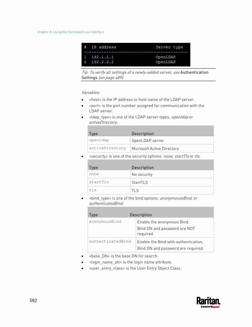
Chapter 8: Using the Command Line Interface
582
Tip: To verify all settings of a newly-added server, see Authentication Settings (on page 489).
Variables:
<host> is the IP address or host name of the LDAP server. <port> is the port number assigned for communication with the
LDAP server. <ldap_type> is one of the LDAP server types: openldap or
activeDirectory.
Type Description openldap OpenLDAP server
activeDirectory Microsoft Active Directory
<security> is one of the security options: none, startTls or tls.
Type Description none No security
startTls StartTLS
tls TLS
<bind_type> is one of the bind options: anonymouseBind, or authenticatedBind.
Type Description anonymousBind Enable the anonymous Bind.
Bind DN and password are NOT required.
authenticatedBind Enable the Bind with authentication. Bind DN and password are required.
<base_DN> is the base DN for search. <login_name_att> is the login name attribute. <user_entry_class> is the User Entry Object Class.
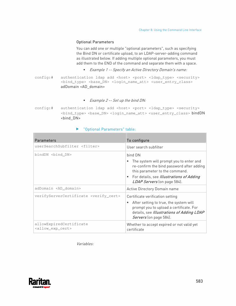
Chapter 8: Using the Command Line Interface
583
Optional Parameters
You can add one or multiple "optional parameters", such as specifying the Bind DN or certificate upload, to an LDAP-server-adding command as illustrated below. If adding multiple optional parameters, you must add them to the END of the command and separate them with a space.
Example 1 -- Specify an Active Directory Domain's name:
config:# authentication ldap add <host> <port> <ldap_type> <security> <bind_type> <base_DN> <login_name_att> <user_entry_class> adDomain <AD_domain>
Example 2 -- Set up the bind DN:
config:# authentication ldap add <host> <port> <ldap_type> <security> <bind_type> <base_DN> <login_name_att> <user_entry_class> bindDN <bind_DN>
"Optional Parameters" table:
Parameters To configure userSearchSubfilter <filter> User search subfilter
bindDN <bind_DN> bind DN The system will prompt you to enter and
re-confirm the bind password after adding this parameter to the command.
For details, see Illustrations of Adding LDAP Servers (on page 584).
adDomain <AD_domain> Active Directory Domain name
verifyServerCertificate <verify_cert> Certificate verification setting After setting to true, the system will
prompt you to upload a certificate. For details, see Illustrations of Adding LDAP Servers (on page 584).
allowExpiredCertificate <allow_exp_cert>
Whether to accept expired or not valid yet certificate
Variables:
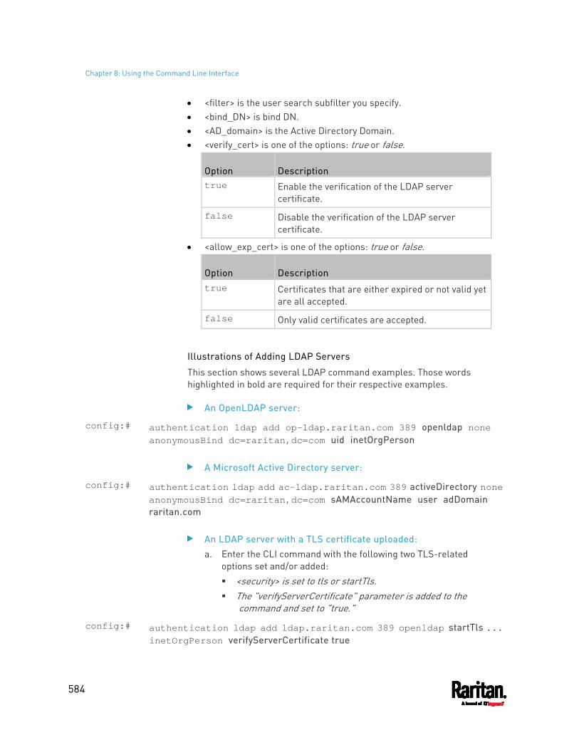
Chapter 8: Using the Command Line Interface
584
<filter> is the user search subfilter you specify. <bind_DN> is bind DN. <AD_domain> is the Active Directory Domain. <verify_cert> is one of the options: true or false.
Option Description true Enable the verification of the LDAP server
certificate.
false Disable the verification of the LDAP server certificate.
<allow_exp_cert> is one of the options: true or false.
Option Description true Certificates that are either expired or not valid yet
are all accepted.
false Only valid certificates are accepted.
Illustrations of Adding LDAP Servers
This section shows several LDAP command examples. Those words highlighted in bold are required for their respective examples.
An OpenLDAP server:
config:# authentication ldap add op-ldap.raritan.com 389 openldap none anonymousBind dc=raritan,dc=com uid inetOrgPerson
A Microsoft Active Directory server:
config:# authentication ldap add ac-ldap.raritan.com 389 activeDirectory none anonymousBind dc=raritan,dc=com sAMAccountName user adDomain raritan.com
An LDAP server with a TLS certificate uploaded: a. Enter the CLI command with the following two TLS-related
options set and/or added: <security> is set to tls or startTls. The "verifyServerCertificate" parameter is added to the
command and set to "true."
config:# authentication ldap add ldap.raritan.com 389 openldap startTls ... inetOrgPerson verifyServerCertificate true
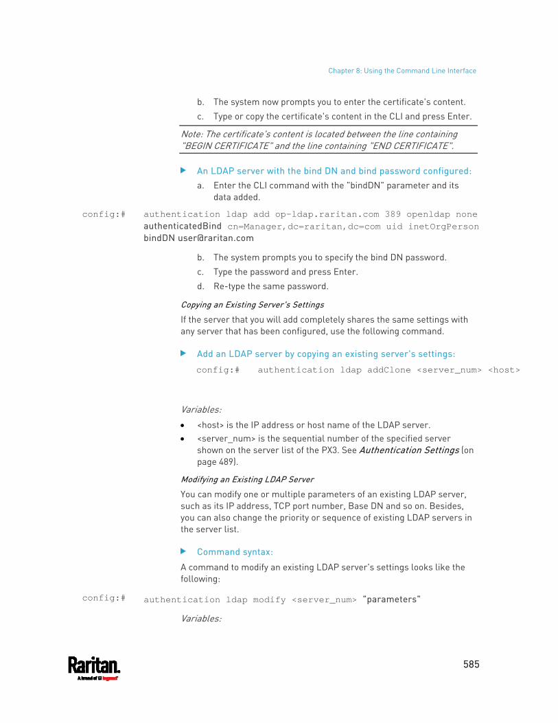
Chapter 8: Using the Command Line Interface
585
b. The system now prompts you to enter the certificate's content. c. Type or copy the certificate's content in the CLI and press Enter.
Note: The certificate's content is located between the line containing "BEGIN CERTIFICATE" and the line containing "END CERTIFICATE".
An LDAP server with the bind DN and bind password configured: a. Enter the CLI command with the "bindDN" parameter and its
data added.
config:# authentication ldap add op-ldap.raritan.com 389 openldap none authenticatedBind cn=Manager,dc=raritan,dc=com uid inetOrgPerson bindDN [email protected]
b. The system prompts you to specify the bind DN password. c. Type the password and press Enter. d. Re-type the same password.
Copying an Existing Server's Settings
If the server that you will add completely shares the same settings with any server that has been configured, use the following command.
Add an LDAP server by copying an existing server's settings:
config:# authentication ldap addClone <server_num> <host>
Variables:
<host> is the IP address or host name of the LDAP server. <server_num> is the sequential number of the specified server
shown on the server list of the PX3. See Authentication Settings (on page 489).
Modifying an Existing LDAP Server
You can modify one or multiple parameters of an existing LDAP server, such as its IP address, TCP port number, Base DN and so on. Besides, you can also change the priority or sequence of existing LDAP servers in the server list.
Command syntax:
A command to modify an existing LDAP server's settings looks like the following:
config:# authentication ldap modify <server_num> "parameters"
Variables:

Chapter 8: Using the Command Line Interface
586
<server_num> is the sequential number of the specified server in the LDAP server list.
Replace "parameters" with one or multiple commands in the following table, depending on which parameter(s) you want to modify.
A list of "parameters":
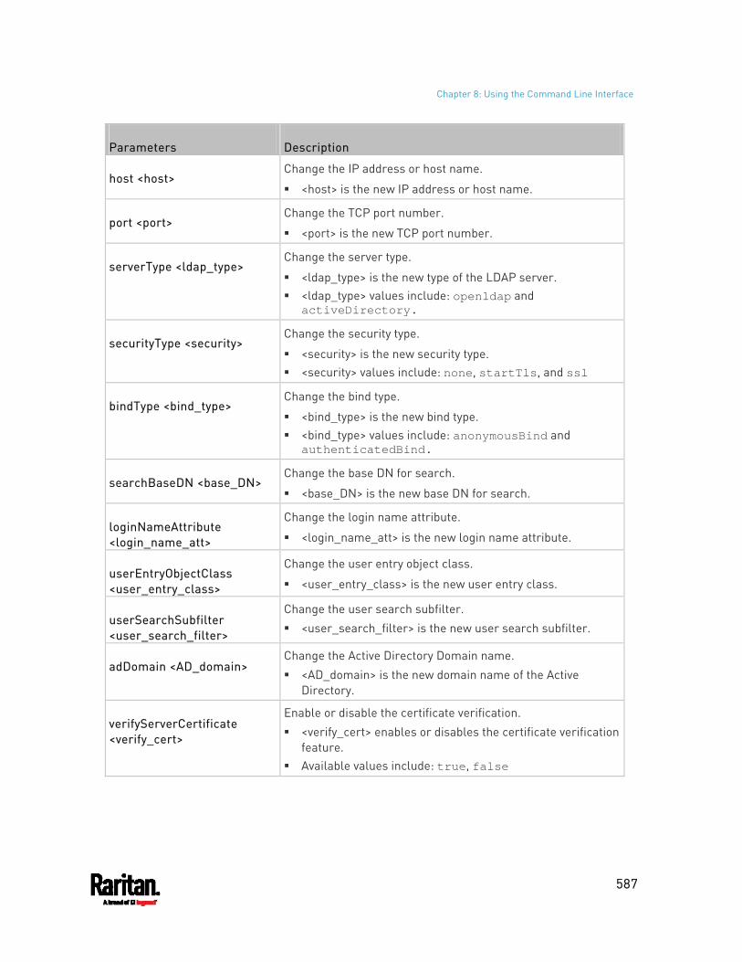
Chapter 8: Using the Command Line Interface
587
Parameters Description
host <host> Change the IP address or host name.
<host> is the new IP address or host name.
port <port> Change the TCP port number.
<port> is the new TCP port number.
serverType <ldap_type> Change the server type.
<ldap_type> is the new type of the LDAP server. <ldap_type> values include: openldap and
activeDirectory.
securityType <security> Change the security type.
<security> is the new security type. <security> values include: none, startTls, and ssl
bindType <bind_type> Change the bind type.
<bind_type> is the new bind type. <bind_type> values include: anonymousBind and
authenticatedBind.
searchBaseDN <base_DN> Change the base DN for search.
<base_DN> is the new base DN for search.
loginNameAttribute <login_name_att>
Change the login name attribute.
<login_name_att> is the new login name attribute.
userEntryObjectClass <user_entry_class>
Change the user entry object class.
<user_entry_class> is the new user entry class.
userSearchSubfilter <user_search_filter>
Change the user search subfilter. <user_search_filter> is the new user search subfilter.
adDomain <AD_domain> Change the Active Directory Domain name. <AD_domain> is the new domain name of the Active
Directory.
verifyServerCertificate <verify_cert>
Enable or disable the certificate verification. <verify_cert> enables or disables the certificate verification
feature. Available values include: true, false
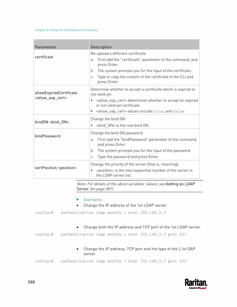
Chapter 8: Using the Command Line Interface
588
Parameters Description
certificate Re-upload a different certificate. a. First add the "certificate" parameter to the command, and
press Enter. b. The system prompts you for the input of the certificate. c. Type or copy the content of the certificate in the CLI and
press Enter.
allowExpiredCertificate <allow_exp_cert>
Determine whether to accept a certificate which is expired or not valid yet. <allow_exp_cert> determines whether to accept an expired
or not valid yet certificate <allow_exp_cert> values include: true, and false
bindDN <bind_DN> Change the bind DN.
<bind_DN> is the new bind DN.
bindPassword Change the bind DN password.
a. First add the "bindPassword" parameter to the command, and press Enter.
b. The system prompts you for the input of the password. c. Type the password and press Enter.
sortPosition <position> Change the priority of the server (that is, resorting). <position> is the new sequential number of the server in
the LDAP server list.
Note: For details of the above variables' values, see Adding an LDAP Server (on page 581).
Examples: Change the IP address of the 1st LDAP server
config:# authentication ldap modify 1 host 192.168.3.3
Change both the IP address and TCP port of the 1st LDAP server
config:# authentication ldap modify 1 host 192.168.3.3 port 633
Change the IP address, TCP port and the type of the L1st DAP server
config:# authentication ldap modify 1 host 192.168.3.3 port 633
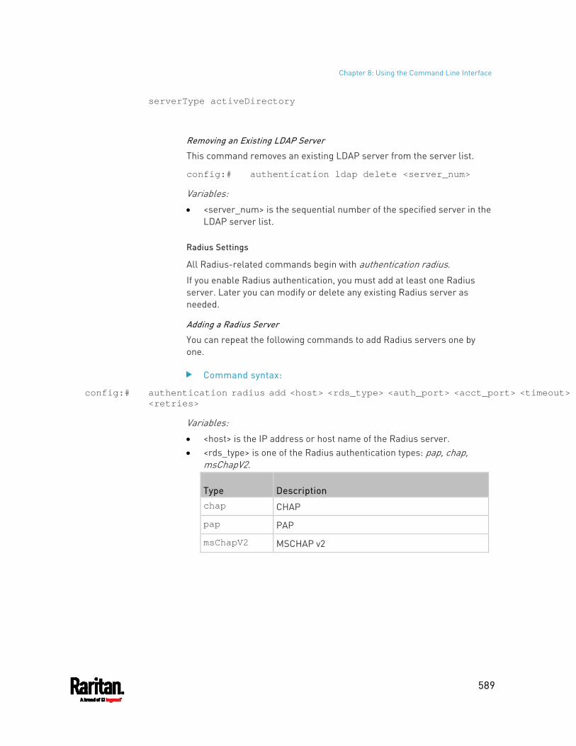
Chapter 8: Using the Command Line Interface
589
serverType activeDirectory
Removing an Existing LDAP Server
This command removes an existing LDAP server from the server list.
config:# authentication ldap delete <server_num>
Variables:
<server_num> is the sequential number of the specified server in the LDAP server list.
Radius Settings
All Radius-related commands begin with authentication radius.
If you enable Radius authentication, you must add at least one Radius server. Later you can modify or delete any existing Radius server as needed.
Adding a Radius Server
You can repeat the following commands to add Radius servers one by one.
Command syntax:
config:# authentication radius add <host> <rds_type> <auth_port> <acct_port> <timeout> <retries>
Variables:
<host> is the IP address or host name of the Radius server. <rds_type> is one of the Radius authentication types: pap, chap,
msChapV2.
Type Description chap CHAP
pap PAP
msChapV2 MSCHAP v2
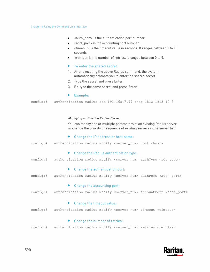
Chapter 8: Using the Command Line Interface
590
<auth_port> is the authentication port number. <acct_port> is the accounting port number. <timeout> is the timeout value in seconds. It ranges between 1 to 10
seconds. <retries> is the number of retries. It ranges between 0 to 5.
To enter the shared secret: 1. After executing the above Radius command, the system
automatically prompts you to enter the shared secret. 2. Type the secret and press Enter. 3. Re-type the same secret and press Enter.
Example:
config:# authentication radius add 192.168.7.99 chap 1812 1813 10 3
Modifying an Existing Radius Server
You can modify one or multiple parameters of an existing Radius server, or change the priority or sequence of existing servers in the server list.
Change the IP address or host name:
config:# authentication radius modify <server_num> host <host>
Change the Radius authentication type:
config:# authentication radius modify <server_num> authType <rds_type>
Change the authentication port:
config:# authentication radius modify <server_num> authPort <auth_port>
Change the accounting port:
config:# authentication radius modify <server_num> accountPort <acct_port>
Change the timeout value:
config:# authentication radius modify <server_num> timeout <timeout>
Change the number of retries:
config:# authentication radius modify <server_num> retries <retries>
Chapter 8: Using the Command Line Interface
591
Change the shared secret:
config:# authentication radius modify <server_num> secret
Change the priority of the specified server:
config:# authentication radius modify <server_num> sortPositon <position>
Tip: You can add more than one parameters to the command. For example, "authentication radius modify <server_num> host <host> authType <rds_type> authPort <auth_port> accountPort <acct_port> ...".
Variables:
<server_num> is the sequential number of the specified server in the Radius server list.
<host> is the new IP address or host name of the Radius server. <rds_type> is one of the Radius authentication types: pap, chap,
msChapV2. <auth_port> is the new authentication port number. <acct_port> is the new accounting port number. <timeout> is the new timeout value in seconds. It ranges between 1
to 10 seconds. <retries> is the new number of retries. It ranges between 0 to 5.
To enter the shared secret: 1. After executing the above Radius command, the system
automatically prompts you to enter the shared secret. 2. Type the secret and press Enter. 3. Re-type the same secret and press Enter.
Example:
config:# authentication radius add 192.168.7.99 chap 1812 1813 10 3
Removing an Existing Radius Server
This command removes an existing Radius server from the server list.
config:# authentication radius delete <server_num>
Variables:
Chapter 8: Using the Command Line Interface
592
<server_num> is the sequential number of the specified server in the Radius server list.
Environmental Sensor Configuration Commands
An environmental sensor configuration command begins with externalsensor. You can configure the name and location parameters of an individual environmental sensor.
Note: To configure an actuator, see Actuator Configuration Commands (on page 611).
Changing the Sensor Name
This command names an environmental sensor.
config:# externalsensor <n> name "<name>"
Variables: <n> is the ID number of the environmental sensor that you want to
configure. The ID number is available in the PX3 web interface or using the command "show externalsensors <n>" in the CLI. It is an integer between 1 and 32.
<name> is a string comprising up to 64 ASCII printable characters. The <name> variable must be enclosed in quotes when it contains spaces.
Note: To name an actuator, see Actuator Configuration Commands (on page 611).
Specifying the CC Sensor Type
Raritan's contact closure sensor (DPX-CC2-TR) supports the connection of diverse third-party or Raritan's detectors/switches. You must specify the type of connected detector/switch for proper operation. Use this command when you need to specify the sensor type.
config:# externalsensor <n> sensorSubType <sensor_type>
Variables:
Chapter 8: Using the Command Line Interface
593
<n> is the ID number of the environmental sensor that you want to configure. The ID number is available in the PX3 web interface or using the command "show externalsensors <n>" in the CLI. It is an integer between 1 and 32.
<sensor_type> is one of these types: contact, smokeDetection, waterDetection or vibration.
Type Description
contact The connected detector/switch is for detection of door lock or door closed/open status.
smokeDetection The connected detector/switch is for detection of the smoke presence.
waterDetection The connected detector/switch is for detection of the water presence.
vibration The connected detector/switch is for detection of the vibration.
Setting the X Coordinate
This command specifies the X coordinate of an environmental sensor.
config:# externalsensor <n> xlabel "<coordinate>"
Variables: <n> is the ID number of the environmental sensor that you want to
configure. The ID number is available in the PX3 web interface or using the command "show externalsensors <n>" in the CLI. It is an integer between 1 and 32.
<coordinate> is a string comprising up to 24 ASCII printable characters, and it must be enclosed in quotes.
Setting the Y Coordinate
This command specifies the Y coordinate of an environmental sensor.
config:# externalsensor <n> ylabel "<coordinate>"
Variables:
Chapter 8: Using the Command Line Interface
594
<n> is the ID number of the environmental sensor that you want to configure. The ID number is available in the PX3 web interface or using the command "show externalsensors <n>" in the CLI. It is an integer between 1 and 32.
<coordinate> is a string comprising up to 24 ASCII printable characters, and it must be enclosed in quotes.
Setting the Z Coordinate
This command specifies the Z coordinate of an environmental sensor.
config:# externalsensor <n> zlabel "<coordinate>"
Variables:
<n> is the ID number of the environmental sensor that you want to configure. The ID number is available in the PX3 web interface or using the command "show externalsensors <n>" in the CLI. It is an integer between 1 and 32.
Depending on the Z coordinate format you set, there are two types of values for the <coordinate> variable:
Type Description
Free form <coordinate> is a string comprising up to 24 ASCII printable characters, and it must be enclosed in quotes.
Rack units <coordinate> is an integer number in rack units.
Note: To specify the Z coordinate using the rack units, see Setting the Z Coordinate Format for Environmental Sensors (on page 507).
Changing the Sensor Description
This command provides a description for a specific environmental sensor.
config:# externalsensor <n> description "<description>"
Variables:
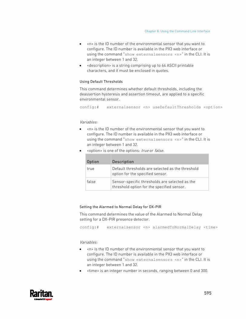
Chapter 8: Using the Command Line Interface
595
<n> is the ID number of the environmental sensor that you want to configure. The ID number is available in the PX3 web interface or using the command "show externalsensors <n>" in the CLI. It is an integer between 1 and 32.
<description> is a string comprising up to 64 ASCII printable characters, and it must be enclosed in quotes.
Using Default Thresholds
This command determines whether default thresholds, including the deassertion hysteresis and assertion timeout, are applied to a specific environmental sensor.
config:# externalsensor <n> useDefaultThresholds <option>
Variables: <n> is the ID number of the environmental sensor that you want to
configure. The ID number is available in the PX3 web interface or using the command "show externalsensors <n>" in the CLI. It is an integer between 1 and 32.
<option> is one of the options: true or false.
Option Description
true Default thresholds are selected as the threshold option for the specified sensor.
false Sensor-specific thresholds are selected as the threshold option for the specified sensor.
Setting the Alarmed to Normal Delay for DX-PIR
This command determines the value of the Alarmed to Normal Delay setting for a DX-PIR presence detector.
config:# externalsensor <n> alarmedToNormalDelay <time>
Variables: <n> is the ID number of the environmental sensor that you want to
configure. The ID number is available in the PX3 web interface or using the command "show externalsensors <n>" in the CLI. It is an integer between 1 and 32.
<time> is an integer number in seconds, ranging between 0 and 300.

Chapter 8: Using the Command Line Interface
596
Examples
This section illustrates several environmental sensor configuration examples.
Example 1 - Environmental Sensor Naming
The following command assigns the name "Cabinet humidity" to the environmental sensor with the ID number 4.
config:# externalsensor 4 name "Cabinet humidity"
Example 2 - Sensor Threshold Selection
The following command sets the environmental sensor #1 to use the default thresholds, including the deassertion hysteresis and assertion timeout, as its threshold settings.
config:# externalsensor 1 useDefaultThresholds true
Configuring Environmental Sensors' Default Thresholds
You can set the default values of upper and lower thresholds, deassertion hysteresis and assertion timeout on a sensor type basis, including temperature, humidity, air pressure and air flow sensors. The default thresholds automatically apply to all environmental sensors that are newly detected or added.
A default threshold configuration command begins with defaultThresholds.
You can configure various default threshold settings for the same sensor type at a time by combining multiple commands. See Multi-Command Syntax (on page 625).
Set the Default Upper Critical Threshold for a specific sensor type:
config:# defaultThresholds <sensor type> upperCritical <value>
Set the Default Upper Warning Threshold for a specific sensor type:
config:# defaultThresholds <sensor type> upperWarning <value>
Set the Default Lower Critical Threshold for a specific sensor type:
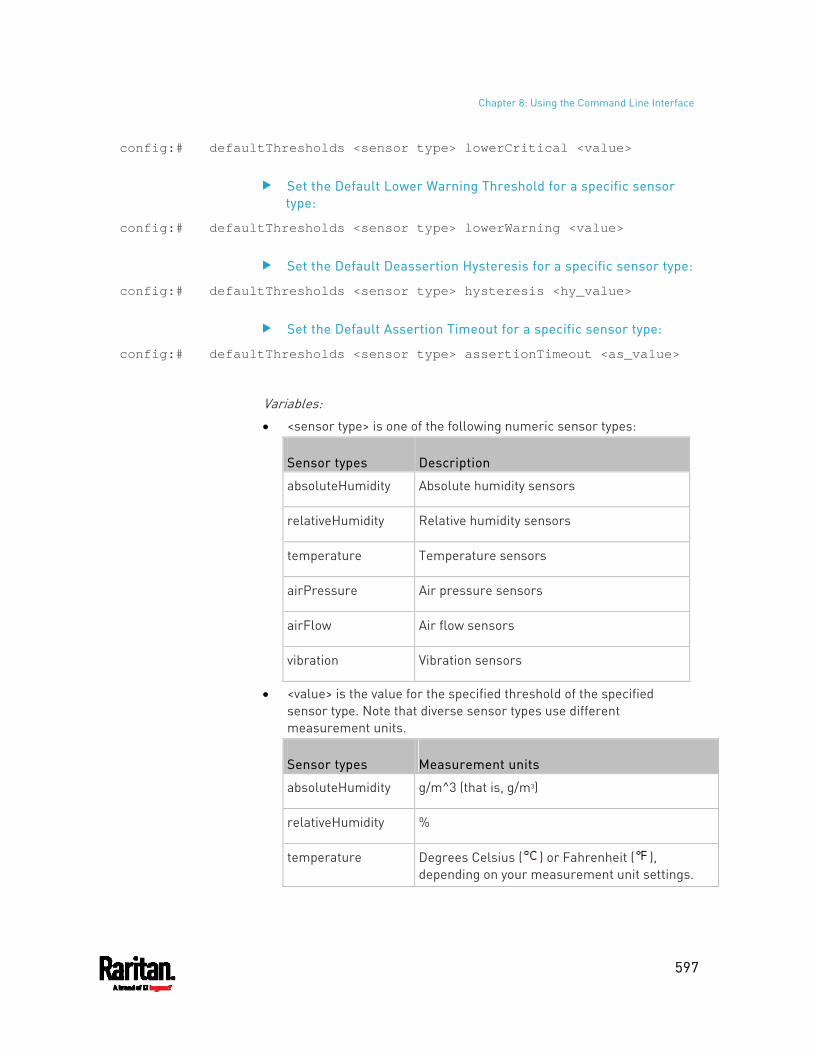
Chapter 8: Using the Command Line Interface
597
config:# defaultThresholds <sensor type> lowerCritical <value>
Set the Default Lower Warning Threshold for a specific sensor type:
config:# defaultThresholds <sensor type> lowerWarning <value>
Set the Default Deassertion Hysteresis for a specific sensor type:
config:# defaultThresholds <sensor type> hysteresis <hy_value>
Set the Default Assertion Timeout for a specific sensor type:
config:# defaultThresholds <sensor type> assertionTimeout <as_value>
Variables: <sensor type> is one of the following numeric sensor types:
Sensor types Description
absoluteHumidity Absolute humidity sensors
relativeHumidity Relative humidity sensors
temperature Temperature sensors
airPressure Air pressure sensors
airFlow Air flow sensors
vibration Vibration sensors
<value> is the value for the specified threshold of the specified sensor type. Note that diverse sensor types use different measurement units.
Sensor types Measurement units
absoluteHumidity g/m^3 (that is, g/m3)
relativeHumidity %
temperature Degrees Celsius ( ) or Fahrenheit ( ), depending on your measurement unit settings.
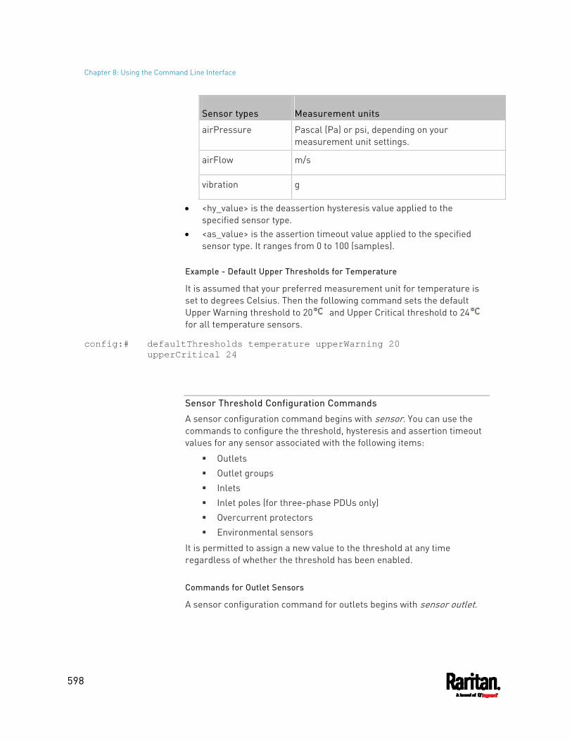
Chapter 8: Using the Command Line Interface
598
Sensor types Measurement units
airPressure Pascal (Pa) or psi, depending on your measurement unit settings.
airFlow m/s
vibration g
<hy_value> is the deassertion hysteresis value applied to the specified sensor type.
<as_value> is the assertion timeout value applied to the specified sensor type. It ranges from 0 to 100 (samples).
Example - Default Upper Thresholds for Temperature
It is assumed that your preferred measurement unit for temperature is set to degrees Celsius. Then the following command sets the default Upper Warning threshold to 20 and Upper Critical threshold to 24 for all temperature sensors.
config:# defaultThresholds temperature upperWarning 20 upperCritical 24
Sensor Threshold Configuration Commands
A sensor configuration command begins with sensor. You can use the commands to configure the threshold, hysteresis and assertion timeout values for any sensor associated with the following items:
Outlets Outlet groups Inlets Inlet poles (for three-phase PDUs only) Overcurrent protectors Environmental sensors
It is permitted to assign a new value to the threshold at any time regardless of whether the threshold has been enabled.
Commands for Outlet Sensors
A sensor configuration command for outlets begins with sensor outlet.
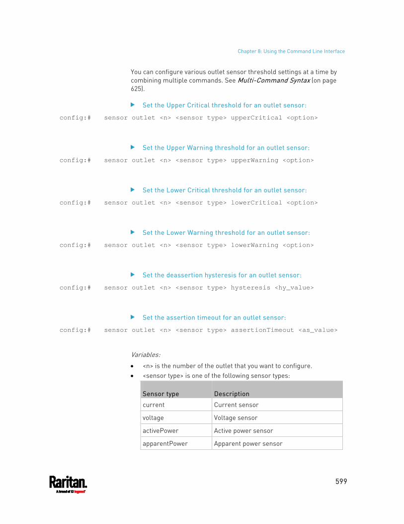
Chapter 8: Using the Command Line Interface
599
You can configure various outlet sensor threshold settings at a time by combining multiple commands. See Multi-Command Syntax (on page 625).
Set the Upper Critical threshold for an outlet sensor:
config:# sensor outlet <n> <sensor type> upperCritical <option>
Set the Upper Warning threshold for an outlet sensor:
config:# sensor outlet <n> <sensor type> upperWarning <option>
Set the Lower Critical threshold for an outlet sensor:
config:# sensor outlet <n> <sensor type> lowerCritical <option>
Set the Lower Warning threshold for an outlet sensor:
config:# sensor outlet <n> <sensor type> lowerWarning <option>
Set the deassertion hysteresis for an outlet sensor:
config:# sensor outlet <n> <sensor type> hysteresis <hy_value>
Set the assertion timeout for an outlet sensor:
config:# sensor outlet <n> <sensor type> assertionTimeout <as_value>
Variables: <n> is the number of the outlet that you want to configure. <sensor type> is one of the following sensor types:
Sensor type Description
current Current sensor
voltage Voltage sensor
activePower Active power sensor
apparentPower Apparent power sensor
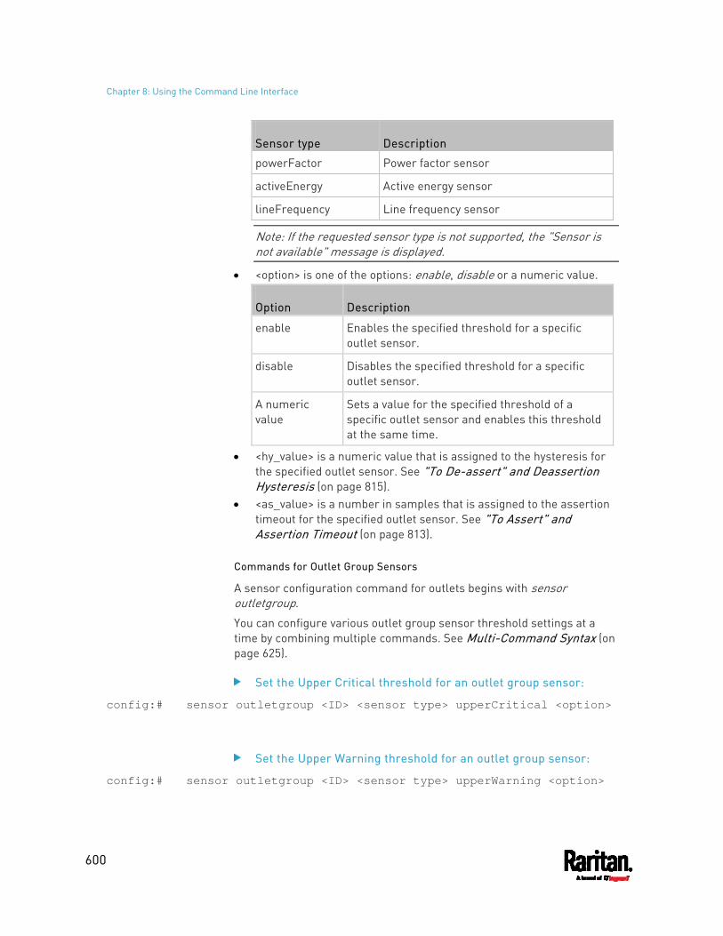
Chapter 8: Using the Command Line Interface
600
Sensor type Description
powerFactor Power factor sensor
activeEnergy Active energy sensor
lineFrequency Line frequency sensor
Note: If the requested sensor type is not supported, the "Sensor is not available" message is displayed.
<option> is one of the options: enable, disable or a numeric value.
Option Description
enable Enables the specified threshold for a specific outlet sensor.
disable Disables the specified threshold for a specific outlet sensor.
A numeric value
Sets a value for the specified threshold of a specific outlet sensor and enables this threshold at the same time.
<hy_value> is a numeric value that is assigned to the hysteresis for the specified outlet sensor. See "To De-assert" and Deassertion Hysteresis (on page 815).
<as_value> is a number in samples that is assigned to the assertion timeout for the specified outlet sensor. See "To Assert" and Assertion Timeout (on page 813).
Commands for Outlet Group Sensors
A sensor configuration command for outlets begins with sensor outletgroup.
You can configure various outlet group sensor threshold settings at a time by combining multiple commands. See Multi-Command Syntax (on page 625).
Set the Upper Critical threshold for an outlet group sensor:
config:# sensor outletgroup <ID> <sensor type> upperCritical <option>
Set the Upper Warning threshold for an outlet group sensor:
config:# sensor outletgroup <ID> <sensor type> upperWarning <option>
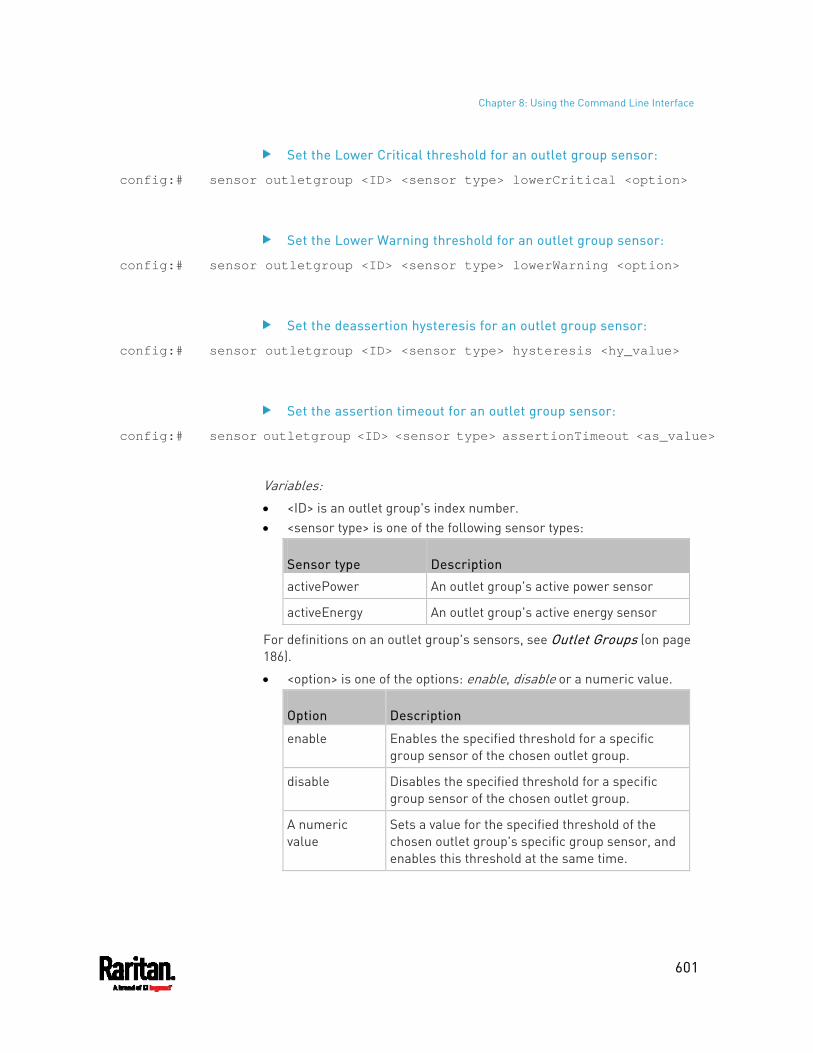
Chapter 8: Using the Command Line Interface
601
Set the Lower Critical threshold for an outlet group sensor:
config:# sensor outletgroup <ID> <sensor type> lowerCritical <option>
Set the Lower Warning threshold for an outlet group sensor:
config:# sensor outletgroup <ID> <sensor type> lowerWarning <option>
Set the deassertion hysteresis for an outlet group sensor:
config:# sensor outletgroup <ID> <sensor type> hysteresis <hy_value>
Set the assertion timeout for an outlet group sensor:
config:# sensor outletgroup <ID> <sensor type> assertionTimeout <as_value>
Variables: <ID> is an outlet group's index number. <sensor type> is one of the following sensor types:
Sensor type Description
activePower An outlet group's active power sensor
activeEnergy An outlet group's active energy sensor
For definitions on an outlet group's sensors, see Outlet Groups (on page 186).
<option> is one of the options: enable, disable or a numeric value.
Option Description
enable Enables the specified threshold for a specific group sensor of the chosen outlet group.
disable Disables the specified threshold for a specific group sensor of the chosen outlet group.
A numeric value
Sets a value for the specified threshold of the chosen outlet group's specific group sensor, and enables this threshold at the same time.
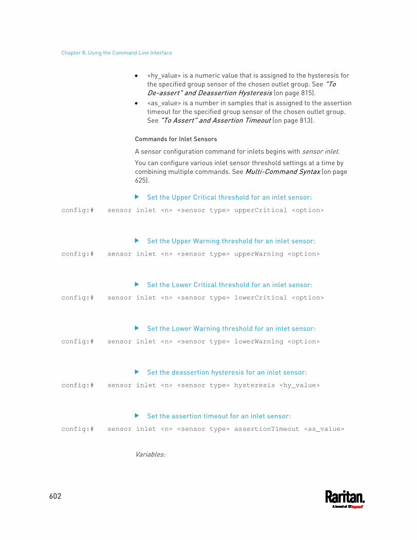
Chapter 8: Using the Command Line Interface
602
<hy_value> is a numeric value that is assigned to the hysteresis for the specified group sensor of the chosen outlet group. See "To De-assert" and Deassertion Hysteresis (on page 815).
<as_value> is a number in samples that is assigned to the assertion timeout for the specified group sensor of the chosen outlet group. See "To Assert" and Assertion Timeout (on page 813).
Commands for Inlet Sensors
A sensor configuration command for inlets begins with sensor inlet. You can configure various inlet sensor threshold settings at a time by combining multiple commands. See Multi-Command Syntax (on page 625).
Set the Upper Critical threshold for an inlet sensor:
config:# sensor inlet <n> <sensor type> upperCritical <option>
Set the Upper Warning threshold for an inlet sensor:
config:# sensor inlet <n> <sensor type> upperWarning <option>
Set the Lower Critical threshold for an inlet sensor:
config:# sensor inlet <n> <sensor type> lowerCritical <option>
Set the Lower Warning threshold for an inlet sensor:
config:# sensor inlet <n> <sensor type> lowerWarning <option>
Set the deassertion hysteresis for an inlet sensor:
config:# sensor inlet <n> <sensor type> hysteresis <hy_value>
Set the assertion timeout for an inlet sensor:
config:# sensor inlet <n> <sensor type> assertionTimeout <as_value>
Variables:
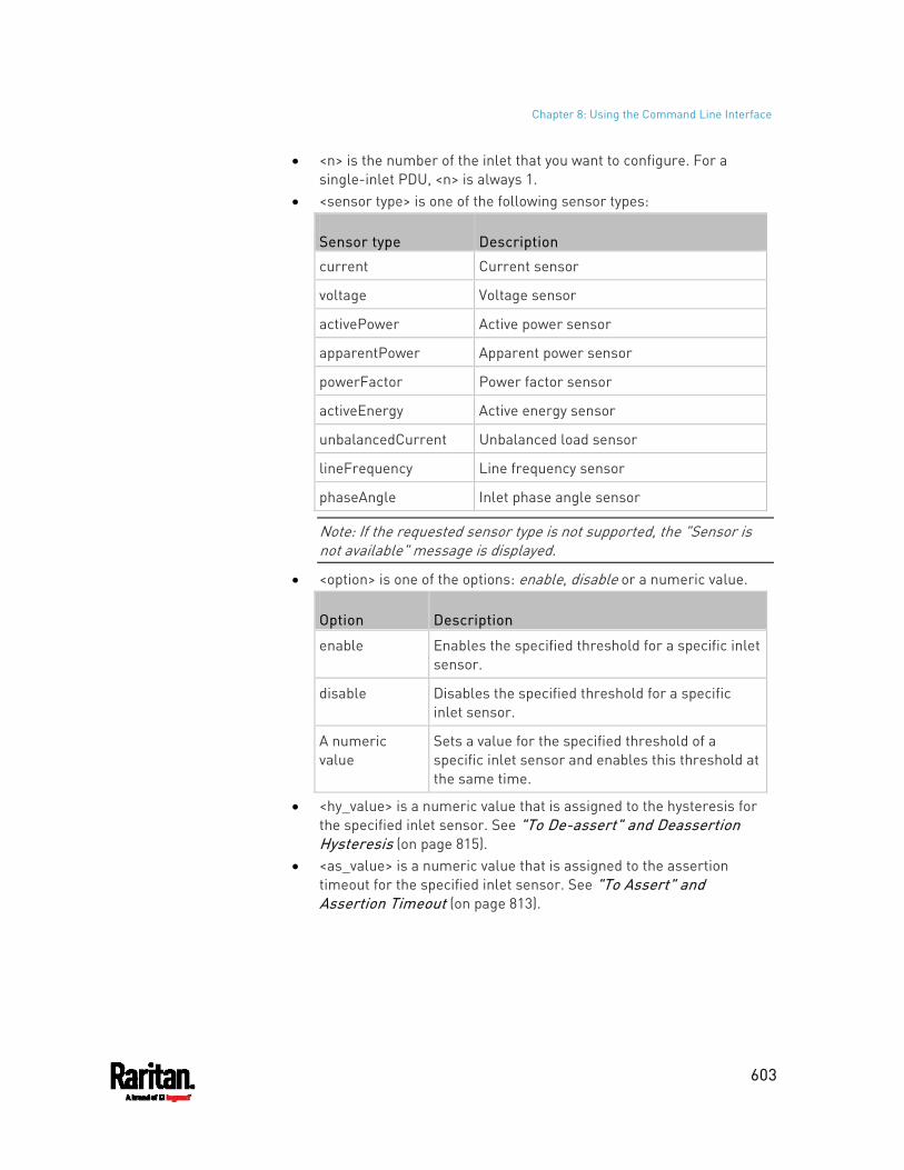
Chapter 8: Using the Command Line Interface
603
<n> is the number of the inlet that you want to configure. For a single-inlet PDU, <n> is always 1.
<sensor type> is one of the following sensor types:
Sensor type Description
current Current sensor
voltage Voltage sensor
activePower Active power sensor
apparentPower Apparent power sensor
powerFactor Power factor sensor
activeEnergy Active energy sensor
unbalancedCurrent Unbalanced load sensor
lineFrequency Line frequency sensor
phaseAngle Inlet phase angle sensor
Note: If the requested sensor type is not supported, the "Sensor is not available" message is displayed.
<option> is one of the options: enable, disable or a numeric value.
Option Description
enable Enables the specified threshold for a specific inlet sensor.
disable Disables the specified threshold for a specific inlet sensor.
A numeric value
Sets a value for the specified threshold of a specific inlet sensor and enables this threshold at the same time.
<hy_value> is a numeric value that is assigned to the hysteresis for the specified inlet sensor. See "To De-assert" and Deassertion Hysteresis (on page 815).
<as_value> is a numeric value that is assigned to the assertion timeout for the specified inlet sensor. See "To Assert" and Assertion Timeout (on page 813).
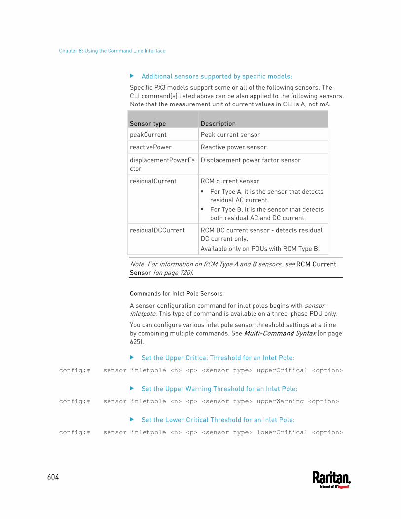
Chapter 8: Using the Command Line Interface
604
Additional sensors supported by specific models:
Specific PX3 models support some or all of the following sensors. The CLI command(s) listed above can be also applied to the following sensors. Note that the measurement unit of current values in CLI is A, not mA.
Sensor type Description
peakCurrent Peak current sensor
reactivePower Reactive power sensor
displacementPowerFactor
Displacement power factor sensor
residualCurrent RCM current sensor For Type A, it is the sensor that detects
residual AC current. For Type B, it is the sensor that detects
both residual AC and DC current.
residualDCCurrent RCM DC current sensor - detects residual DC current only. Available only on PDUs with RCM Type B.
Note: For information on RCM Type A and B sensors, see RCM Current Sensor (on page 720).
Commands for Inlet Pole Sensors
A sensor configuration command for inlet poles begins with sensor inletpole. This type of command is available on a three-phase PDU only.
You can configure various inlet pole sensor threshold settings at a time by combining multiple commands. See Multi-Command Syntax (on page 625).
Set the Upper Critical Threshold for an Inlet Pole:
config:# sensor inletpole <n> <p> <sensor type> upperCritical <option>
Set the Upper Warning Threshold for an Inlet Pole:
config:# sensor inletpole <n> <p> <sensor type> upperWarning <option>
Set the Lower Critical Threshold for an Inlet Pole:
config:# sensor inletpole <n> <p> <sensor type> lowerCritical <option>
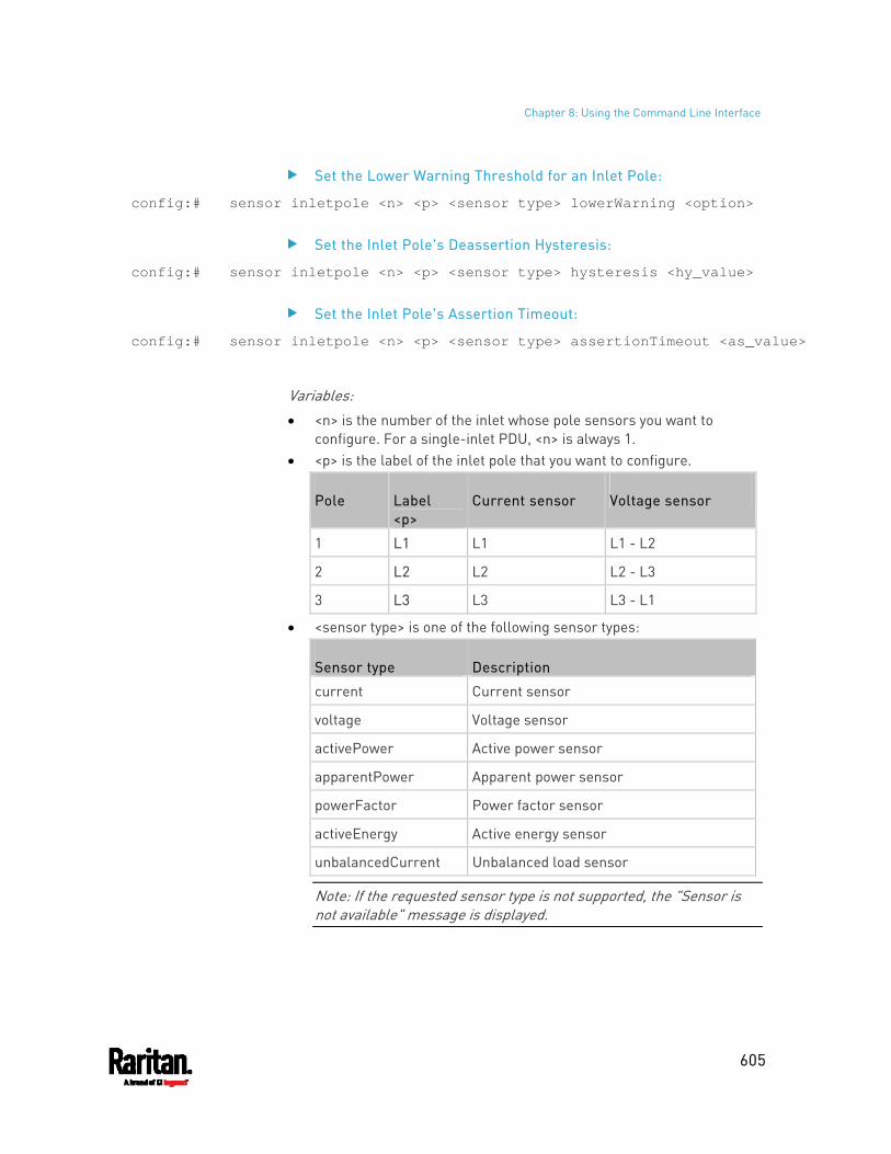
Chapter 8: Using the Command Line Interface
605
Set the Lower Warning Threshold for an Inlet Pole:
config:# sensor inletpole <n> <p> <sensor type> lowerWarning <option>
Set the Inlet Pole's Deassertion Hysteresis:
config:# sensor inletpole <n> <p> <sensor type> hysteresis <hy_value>
Set the Inlet Pole's Assertion Timeout:
config:# sensor inletpole <n> <p> <sensor type> assertionTimeout <as_value>
Variables: <n> is the number of the inlet whose pole sensors you want to
configure. For a single-inlet PDU, <n> is always 1. <p> is the label of the inlet pole that you want to configure.
Pole Label <p>
Current sensor Voltage sensor
1 L1 L1 L1 - L2
2 L2 L2 L2 - L3
3 L3 L3 L3 - L1
<sensor type> is one of the following sensor types:
Sensor type Description
current Current sensor
voltage Voltage sensor
activePower Active power sensor
apparentPower Apparent power sensor
powerFactor Power factor sensor
activeEnergy Active energy sensor
unbalancedCurrent Unbalanced load sensor
Note: If the requested sensor type is not supported, the "Sensor is not available" message is displayed.
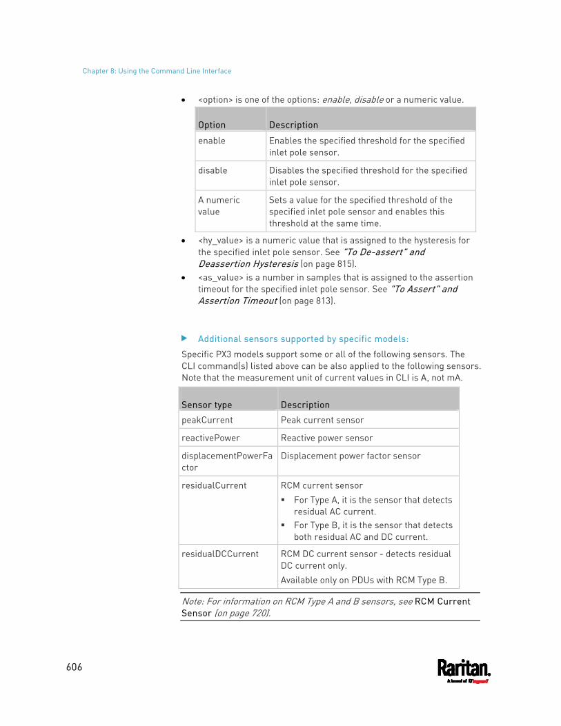
Chapter 8: Using the Command Line Interface
606
<option> is one of the options: enable, disable or a numeric value.
Option Description
enable Enables the specified threshold for the specified inlet pole sensor.
disable Disables the specified threshold for the specified inlet pole sensor.
A numeric value
Sets a value for the specified threshold of the specified inlet pole sensor and enables this threshold at the same time.
<hy_value> is a numeric value that is assigned to the hysteresis for the specified inlet pole sensor. See "To De-assert" and Deassertion Hysteresis (on page 815).
<as_value> is a number in samples that is assigned to the assertion timeout for the specified inlet pole sensor. See "To Assert" and Assertion Timeout (on page 813).
Additional sensors supported by specific models:
Specific PX3 models support some or all of the following sensors. The CLI command(s) listed above can be also applied to the following sensors. Note that the measurement unit of current values in CLI is A, not mA.
Sensor type Description
peakCurrent Peak current sensor
reactivePower Reactive power sensor
displacementPowerFactor
Displacement power factor sensor
residualCurrent RCM current sensor For Type A, it is the sensor that detects
residual AC current. For Type B, it is the sensor that detects
both residual AC and DC current.
residualDCCurrent RCM DC current sensor - detects residual DC current only. Available only on PDUs with RCM Type B.
Note: For information on RCM Type A and B sensors, see RCM Current Sensor (on page 720).
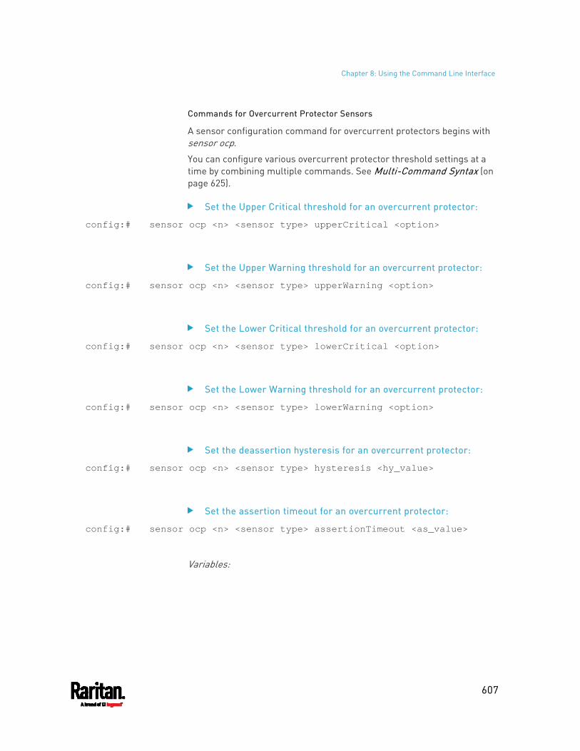
Chapter 8: Using the Command Line Interface
607
Commands for Overcurrent Protector Sensors
A sensor configuration command for overcurrent protectors begins with sensor ocp.
You can configure various overcurrent protector threshold settings at a time by combining multiple commands. See Multi-Command Syntax (on page 625).
Set the Upper Critical threshold for an overcurrent protector:
config:# sensor ocp <n> <sensor type> upperCritical <option>
Set the Upper Warning threshold for an overcurrent protector:
config:# sensor ocp <n> <sensor type> upperWarning <option>
Set the Lower Critical threshold for an overcurrent protector:
config:# sensor ocp <n> <sensor type> lowerCritical <option>
Set the Lower Warning threshold for an overcurrent protector:
config:# sensor ocp <n> <sensor type> lowerWarning <option>
Set the deassertion hysteresis for an overcurrent protector:
config:# sensor ocp <n> <sensor type> hysteresis <hy_value>
Set the assertion timeout for an overcurrent protector:
config:# sensor ocp <n> <sensor type> assertionTimeout <as_value>
Variables:
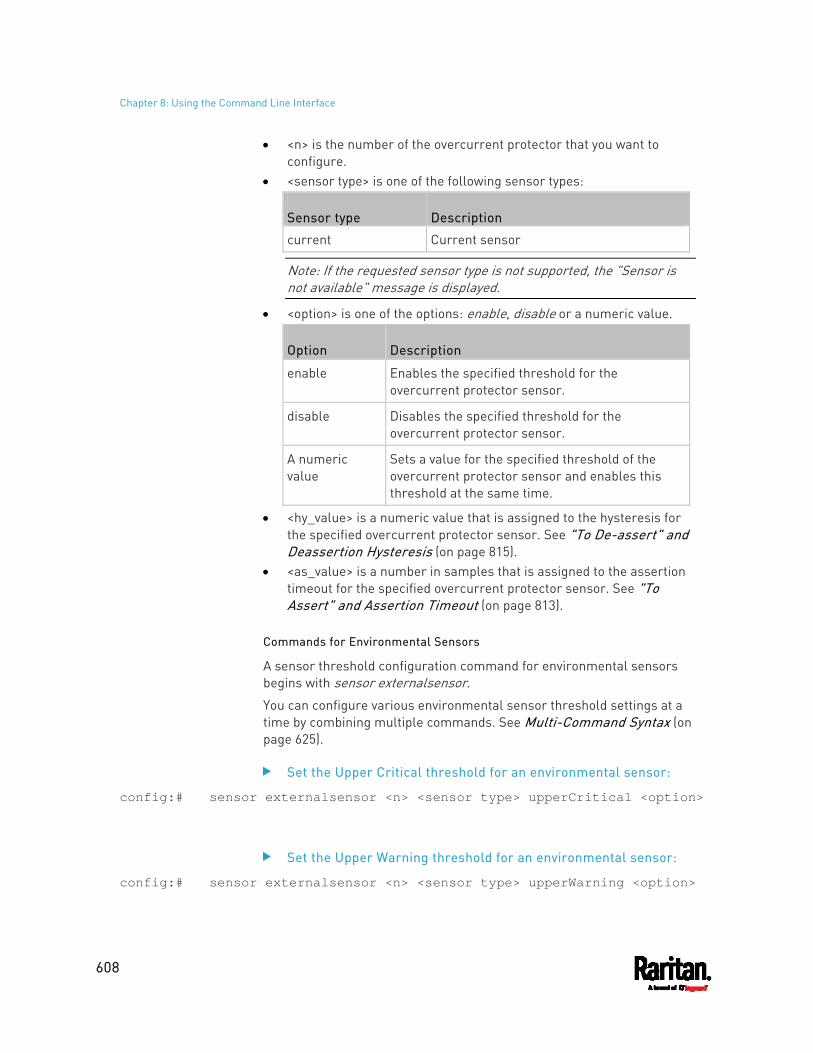
Chapter 8: Using the Command Line Interface
608
<n> is the number of the overcurrent protector that you want to configure.
<sensor type> is one of the following sensor types:
Sensor type Description
current Current sensor
Note: If the requested sensor type is not supported, the "Sensor is not available" message is displayed.
<option> is one of the options: enable, disable or a numeric value.
Option Description
enable Enables the specified threshold for the overcurrent protector sensor.
disable Disables the specified threshold for the overcurrent protector sensor.
A numeric value
Sets a value for the specified threshold of the overcurrent protector sensor and enables this threshold at the same time.
<hy_value> is a numeric value that is assigned to the hysteresis for the specified overcurrent protector sensor. See "To De-assert" and Deassertion Hysteresis (on page 815).
<as_value> is a number in samples that is assigned to the assertion timeout for the specified overcurrent protector sensor. See "To Assert" and Assertion Timeout (on page 813).
Commands for Environmental Sensors
A sensor threshold configuration command for environmental sensors begins with sensor externalsensor.
You can configure various environmental sensor threshold settings at a time by combining multiple commands. See Multi-Command Syntax (on page 625).
Set the Upper Critical threshold for an environmental sensor:
config:# sensor externalsensor <n> <sensor type> upperCritical <option>
Set the Upper Warning threshold for an environmental sensor:
config:# sensor externalsensor <n> <sensor type> upperWarning <option>
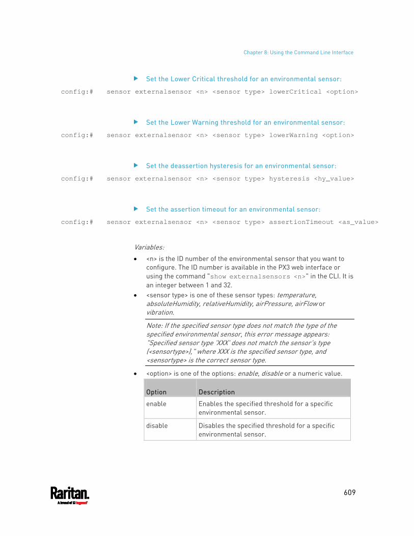
Chapter 8: Using the Command Line Interface
609
Set the Lower Critical threshold for an environmental sensor:
config:# sensor externalsensor <n> <sensor type> lowerCritical <option>
Set the Lower Warning threshold for an environmental sensor:
config:# sensor externalsensor <n> <sensor type> lowerWarning <option>
Set the deassertion hysteresis for an environmental sensor:
config:# sensor externalsensor <n> <sensor type> hysteresis <hy_value>
Set the assertion timeout for an environmental sensor:
config:# sensor externalsensor <n> <sensor type> assertionTimeout <as_value>
Variables: <n> is the ID number of the environmental sensor that you want to
configure. The ID number is available in the PX3 web interface or using the command "show externalsensors <n>" in the CLI. It is an integer between 1 and 32.
<sensor type> is one of these sensor types: temperature, absoluteHumidity, relativeHumidity, airPressure, airFlow or vibration.
Note: If the specified sensor type does not match the type of the specified environmental sensor, this error message appears: "Specified sensor type 'XXX' does not match the sensor's type (<sensortype>)," where XXX is the specified sensor type, and <sensortype> is the correct sensor type.
<option> is one of the options: enable, disable or a numeric value.
Option Description
enable Enables the specified threshold for a specific environmental sensor.
disable Disables the specified threshold for a specific environmental sensor.
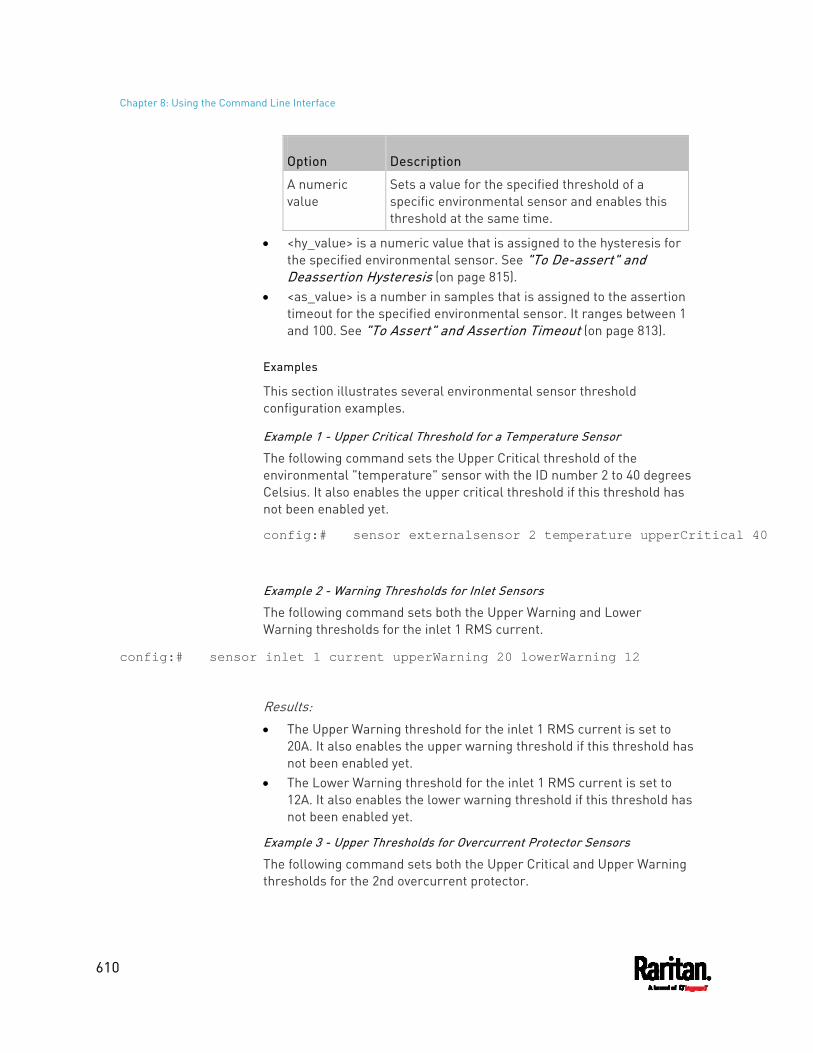
Chapter 8: Using the Command Line Interface
610
Option Description
A numeric value
Sets a value for the specified threshold of a specific environmental sensor and enables this threshold at the same time.
<hy_value> is a numeric value that is assigned to the hysteresis for the specified environmental sensor. See "To De-assert" and Deassertion Hysteresis (on page 815).
<as_value> is a number in samples that is assigned to the assertion timeout for the specified environmental sensor. It ranges between 1 and 100. See "To Assert" and Assertion Timeout (on page 813).
Examples
This section illustrates several environmental sensor threshold configuration examples.
Example 1 - Upper Critical Threshold for a Temperature Sensor
The following command sets the Upper Critical threshold of the environmental "temperature" sensor with the ID number 2 to 40 degrees Celsius. It also enables the upper critical threshold if this threshold has not been enabled yet.
config:# sensor externalsensor 2 temperature upperCritical 40
Example 2 - Warning Thresholds for Inlet Sensors
The following command sets both the Upper Warning and Lower Warning thresholds for the inlet 1 RMS current.
config:# sensor inlet 1 current upperWarning 20 lowerWarning 12
Results: The Upper Warning threshold for the inlet 1 RMS current is set to
20A. It also enables the upper warning threshold if this threshold has not been enabled yet.
The Lower Warning threshold for the inlet 1 RMS current is set to 12A. It also enables the lower warning threshold if this threshold has not been enabled yet.
Example 3 - Upper Thresholds for Overcurrent Protector Sensors
The following command sets both the Upper Critical and Upper Warning thresholds for the 2nd overcurrent protector.
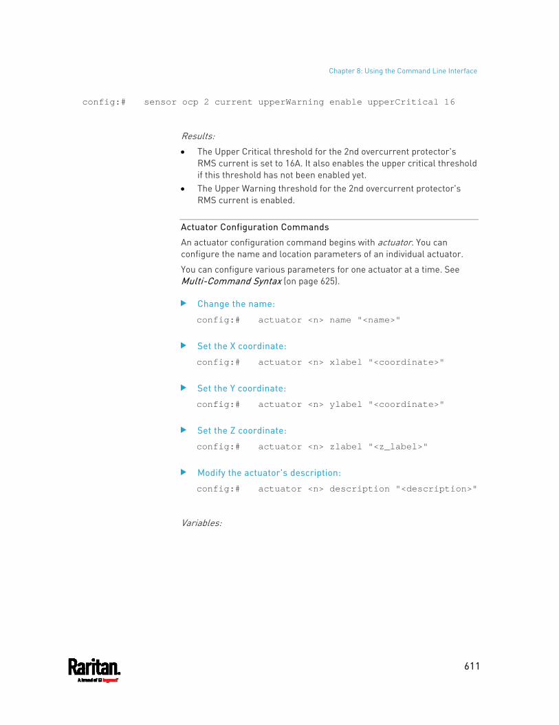
Chapter 8: Using the Command Line Interface
611
config:# sensor ocp 2 current upperWarning enable upperCritical 16
Results: The Upper Critical threshold for the 2nd overcurrent protector's
RMS current is set to 16A. It also enables the upper critical threshold if this threshold has not been enabled yet.
The Upper Warning threshold for the 2nd overcurrent protector's RMS current is enabled.
Actuator Configuration Commands
An actuator configuration command begins with actuator. You can configure the name and location parameters of an individual actuator.
You can configure various parameters for one actuator at a time. See Multi-Command Syntax (on page 625).
Change the name:
config:# actuator <n> name "<name>"
Set the X coordinate:
config:# actuator <n> xlabel "<coordinate>"
Set the Y coordinate:
config:# actuator <n> ylabel "<coordinate>"
Set the Z coordinate:
config:# actuator <n> zlabel "<z_label>"
Modify the actuator's description:
config:# actuator <n> description "<description>"
Variables:
Chapter 8: Using the Command Line Interface
612
<n> is the ID number assigned to the actuator. The ID number can be found using the PX3 web interface or CLI. It is an integer starting at 1.
<name> is a string comprising up to 64 ASCII printable characters. The <name> variable must be enclosed in quotes when it contains spaces.
<coordinate> is a string comprising up to 24 ASCII printable characters, and it must be enclosed in quotes.
There are two types of values for the <z_label> variable, depending on the Z coordinate format you set:
Type Description
Free form <coordinate> is a string comprising up to 24 ASCII printable characters, and it must be enclosed in quotes.
Rack units <coordinate> is an integer number in rack units.
Note: To specify the Z coordinate using the rack units, see Setting the Z Coordinate Format for Environmental Sensors (on page 507).
<description> is a sentence or paragraph comprising up to 64 ASCII printable characters, and it must be enclosed in quotes.
Example - Actuator Naming
The following command assigns the name "Door lock" to the actuator whose ID number is 9.
config:# actuator 9 name "Door lock"
Server Reachability Configuration Commands
You can use the CLI to add or delete an IT device, such as a server, from the server reachability list, or modify the settings for a monitored IT device. A server reachability configuration command begins with serverReachability.
Adding a Monitored Device
This command adds a new IT device to the server reachability list.
config:# serverReachability add <IP_host> <enable> <succ_ping> <fail_ping> <succ_wait> <fail_wait> <resume> <disable_count>
Chapter 8: Using the Command Line Interface
613
Variables: <IP_host> is the IP address or host name of the IT device that you
want to add. <enable> is one of the options: true or false.
Option Description
true Enables the ping monitoring feature for the newly added device.
false Disables the ping monitoring feature for the newly added device.
<succ_ping> is the number of successful pings for declaring the monitored device "Reachable." Valid range is 0 to 200.
<fail_ping> is the number of consecutive unsuccessful pings for declaring the monitored device "Unreachable." Valid range is 1 to 100.
<succ_wait> is the wait time to send the next ping after a successful ping. Valid range is 5 to 600 (seconds).
<fail_wait> is the wait time to send the next ping after a unsuccessful ping. Valid range is 3 to 600 (seconds).
<resume> is the wait time before the PX3 resumes pinging after declaring the monitored device "Unreachable." Valid range is 5 to 120 (seconds).
<disable_count> is the number of consecutive "Unreachable" declarations before the PX3 disables the ping monitoring feature for the monitored device and returns to the "Waiting for reliable connection" state. Valid range is 1 to 100 or unlimited.
Deleting a Monitored Device
This command removes a monitored IT device from the server reachability list.
config:# serverReachability delete <n>
Variables: <n> is a number representing the sequence of the IT device in the
monitored server list. You can find each IT device's sequence number using the CLI command of show serverReachability as illustrated below.
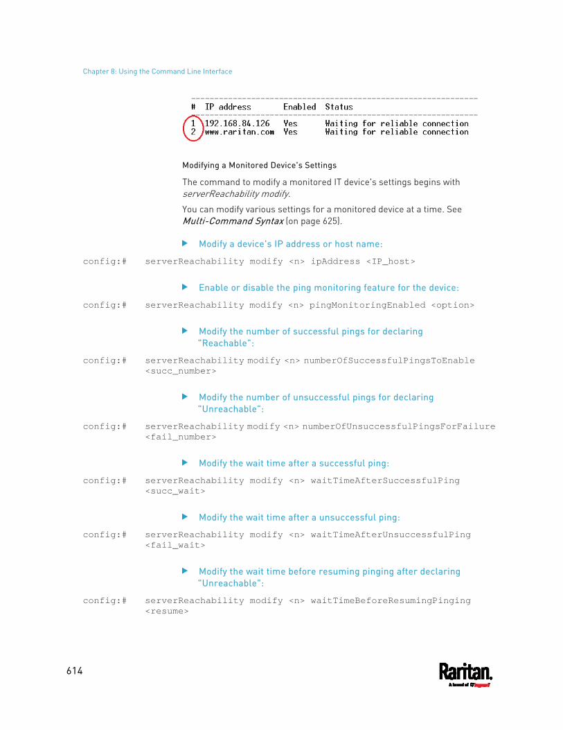
Chapter 8: Using the Command Line Interface
614
Modifying a Monitored Device's Settings
The command to modify a monitored IT device's settings begins with serverReachability modify.
You can modify various settings for a monitored device at a time. See Multi-Command Syntax (on page 625).
Modify a device's IP address or host name:
config:# serverReachability modify <n> ipAddress <IP_host>
Enable or disable the ping monitoring feature for the device:
config:# serverReachability modify <n> pingMonitoringEnabled <option>
Modify the number of successful pings for declaring "Reachable":
config:# serverReachability modify <n> numberOfSuccessfulPingsToEnable <succ_number>
Modify the number of unsuccessful pings for declaring "Unreachable":
config:# serverReachability modify <n> numberOfUnsuccessfulPingsForFailure <fail_number>
Modify the wait time after a successful ping:
config:# serverReachability modify <n> waitTimeAfterSuccessfulPing <succ_wait>
Modify the wait time after a unsuccessful ping:
config:# serverReachability modify <n> waitTimeAfterUnsuccessfulPing <fail_wait>
Modify the wait time before resuming pinging after declaring "Unreachable":
config:# serverReachability modify <n> waitTimeBeforeResumingPinging <resume>
Chapter 8: Using the Command Line Interface
615
Modify the number of consecutive "Unreachable" declarations before disabling the ping monitoring feature:
config:# serverReachability modify <n> numberOfFailuresToDisable <disable_count>
Variables: <n> is a number representing the sequence of the IT device in the
server monitoring list. <IP_host> is the IP address or host name of the IT device whose
settings you want to modify. <option> is one of the options: true or false.
Option Description
true Enables the ping monitoring feature for the monitored device.
false Disables the ping monitoring feature for the monitored device.
<succ_number> is the number of successful pings for declaring the monitored device "Reachable." Valid range is 0 to 200.
<fail_number> is the number of consecutive unsuccessful pings for declaring the monitored device "Unreachable." Valid range is 1 to 100.
<succ_wait> is the wait time to send the next ping after a successful ping. Valid range is 5 to 600 (seconds).
<fail_wait> is the wait time to send the next ping after a unsuccessful ping. Valid range is 3 to 600 (seconds).
<resume> is the wait time before the PX3 resumes pinging after declaring the monitored device "Unreachable." Valid range is 5 to 120 (seconds).
<disable_count> is the number of consecutive "Unreachable" declarations before the PX3 disables the ping monitoring feature for the monitored device and returns to the "Waiting for reliable connection" state. Valid range is 1 to 100 or unlimited.
Example - Server Settings Changed
The following command modifies several ping monitoring settings for the second server in the server reachability list.
config:# serverReachability modify 2 numberOfSuccessfulPingsToEnable 10 numberOfUnsuccessfulPingsForFailure 8
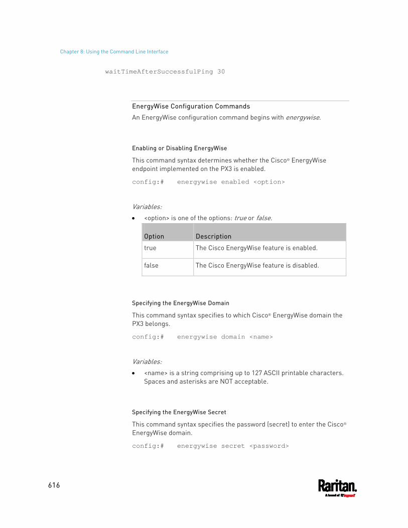
Chapter 8: Using the Command Line Interface
616
waitTimeAfterSuccessfulPing 30
EnergyWise Configuration Commands
An EnergyWise configuration command begins with energywise.
Enabling or Disabling EnergyWise
This command syntax determines whether the Cisco® EnergyWise endpoint implemented on the PX3 is enabled.
config:# energywise enabled <option>
Variables: <option> is one of the options: true or false.
Option Description
true The Cisco EnergyWise feature is enabled.
false The Cisco EnergyWise feature is disabled.
Specifying the EnergyWise Domain
This command syntax specifies to which Cisco® EnergyWise domain the PX3 belongs.
config:# energywise domain <name>
Variables: <name> is a string comprising up to 127 ASCII printable characters.
Spaces and asterisks are NOT acceptable.
Specifying the EnergyWise Secret
This command syntax specifies the password (secret) to enter the Cisco® EnergyWise domain.
config:# energywise secret <password>
Chapter 8: Using the Command Line Interface
617
Variables: <password> is a string comprising up to 127 ASCII printable
characters. Spaces and asterisks are NOT acceptable.
Changing the UDP Port
This command syntax specifies the UDP port for communications in the Cisco® EnergyWise domain.
config:# energywise port <port>
Variables: <port> is the UDP port number ranging between 1 and 65535.
Setting the Polling Interval
This command syntax determines the polling interval at which the Cisco® EnergyWise domain queries the PX3.
config:# energywise polling <timing>
Variables: <timing> is an integer number in seconds. It ranges between 30 and
600 seconds.
Example - Setting Up EnergyWise
The following command sets up two Cisco® EnergyWise-related features.
config:# energywise enabled true port 10288
Results: The EnergyWise feature implemented on the PX3 is enabled. The UDP port is set to 10288.
Asset Management Commands
You can use the CLI commands to change the settings of the connected asset strip (if any) or the settings of LEDs on the asset strip.
Chapter 8: Using the Command Line Interface
618
Asset Strip Management
An asset strip management configuration command begins with assetStrip.
Naming an Asset Strip
This command syntax names or changes the name of an asset strip connected to the PX3 device.
config:# assetStrip <n> name "<name>"
Variables: <n> is the number of the FEATURE port where the selected asset
strip is physically connected. For the PX3 device with only one FEATURE port, the number is always 1.
<name> is a string comprising up to 64 ASCII printable characters. The <name> variable must be enclosed in quotes when it contains spaces.
Specifying the Number of Rack Units
This command syntax specifies the total number of rack units on an asset strip connected to the PX3 device.
config:# assetStrip <n> numberOfRackUnits <number>
Note: A rack unit refers to a tag port on the asset strips.
Variables: <n> is the number of the FEATURE port where the selected asset
strip is physically connected. For the PX3 device with only one FEATURE port, the number is always 1.
<number> is the total number of rack units available on the connected asset strip. This value ranges from 8 to 64.
Specifying the Rack Unit Numbering Mode
This command syntax specifies the numbering mode of rack units on the asset strips connected to the PX3 device. The numbering mode changes the rack unit numbers.
config:# assetStrip <n> rackUnitNumberingMode <mode>
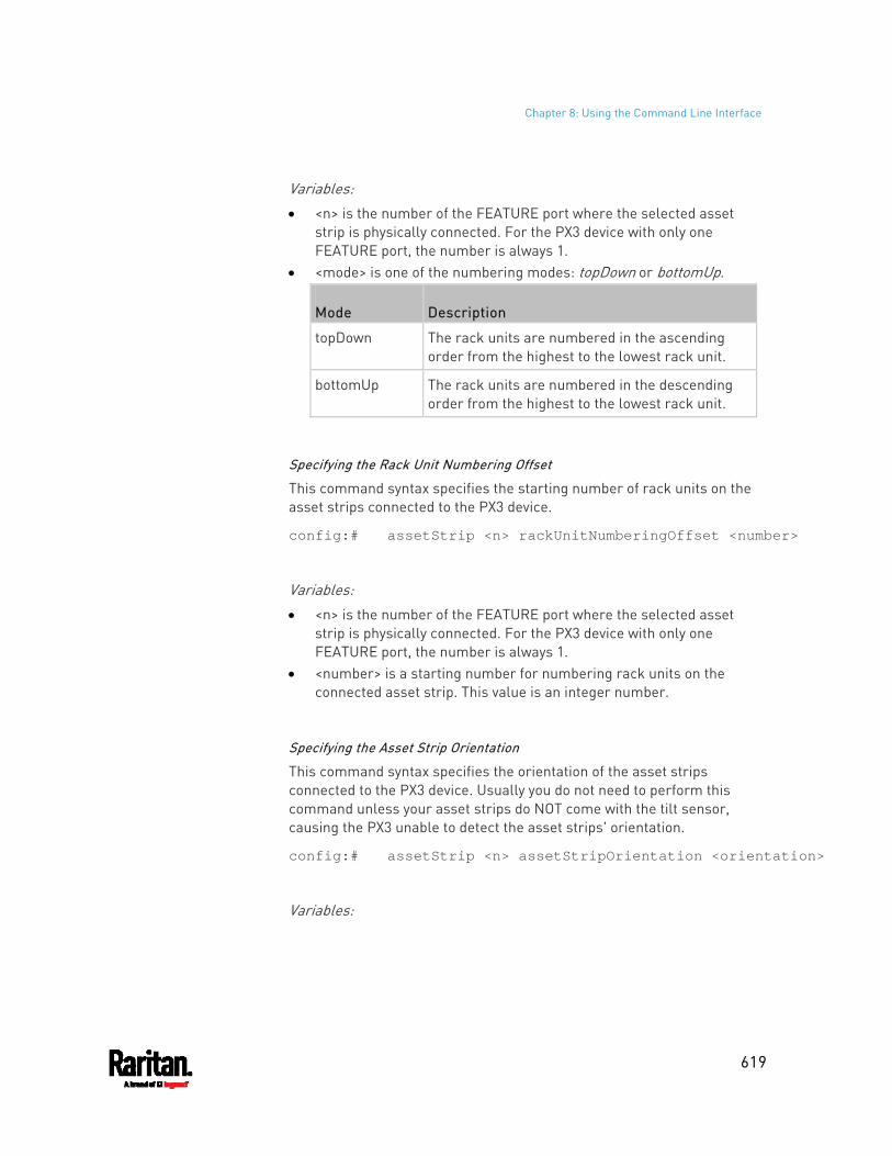
Chapter 8: Using the Command Line Interface
619
Variables: <n> is the number of the FEATURE port where the selected asset
strip is physically connected. For the PX3 device with only one FEATURE port, the number is always 1.
<mode> is one of the numbering modes: topDown or bottomUp.
Mode Description
topDown The rack units are numbered in the ascending order from the highest to the lowest rack unit.
bottomUp The rack units are numbered in the descending order from the highest to the lowest rack unit.
Specifying the Rack Unit Numbering Offset
This command syntax specifies the starting number of rack units on the asset strips connected to the PX3 device.
config:# assetStrip <n> rackUnitNumberingOffset <number>
Variables: <n> is the number of the FEATURE port where the selected asset
strip is physically connected. For the PX3 device with only one FEATURE port, the number is always 1.
<number> is a starting number for numbering rack units on the connected asset strip. This value is an integer number.
Specifying the Asset Strip Orientation
This command syntax specifies the orientation of the asset strips connected to the PX3 device. Usually you do not need to perform this command unless your asset strips do NOT come with the tilt sensor, causing the PX3 unable to detect the asset strips' orientation.
config:# assetStrip <n> assetStripOrientation <orientation>
Variables:
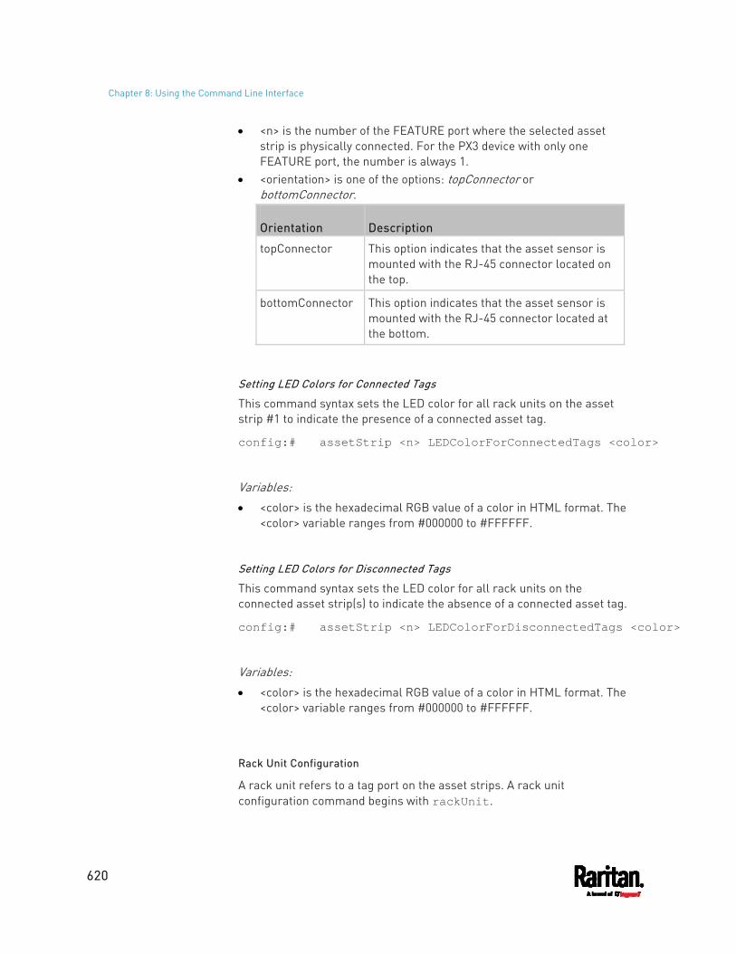
Chapter 8: Using the Command Line Interface
620
<n> is the number of the FEATURE port where the selected asset strip is physically connected. For the PX3 device with only one FEATURE port, the number is always 1.
<orientation> is one of the options: topConnector or bottomConnector.
Orientation Description
topConnector This option indicates that the asset sensor is mounted with the RJ-45 connector located on the top.
bottomConnector This option indicates that the asset sensor is mounted with the RJ-45 connector located at the bottom.
Setting LED Colors for Connected Tags
This command syntax sets the LED color for all rack units on the asset strip #1 to indicate the presence of a connected asset tag.
config:# assetStrip <n> LEDColorForConnectedTags <color>
Variables: <color> is the hexadecimal RGB value of a color in HTML format. The
<color> variable ranges from #000000 to #FFFFFF.
Setting LED Colors for Disconnected Tags
This command syntax sets the LED color for all rack units on the connected asset strip(s) to indicate the absence of a connected asset tag.
config:# assetStrip <n> LEDColorForDisconnectedTags <color>
Variables: <color> is the hexadecimal RGB value of a color in HTML format. The
<color> variable ranges from #000000 to #FFFFFF.
Rack Unit Configuration
A rack unit refers to a tag port on the asset strips. A rack unit configuration command begins with rackUnit.
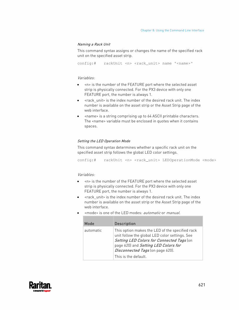
Chapter 8: Using the Command Line Interface
621
Naming a Rack Unit
This command syntax assigns or changes the name of the specified rack unit on the specified asset strip.
config:# rackUnit <n> <rack_unit> name "<name>"
Variables: <n> is the number of the FEATURE port where the selected asset
strip is physically connected. For the PX3 device with only one FEATURE port, the number is always 1.
<rack_unit> is the index number of the desired rack unit. The index number is available on the asset strip or the Asset Strip page of the web interface.
<name> is a string comprising up to 64 ASCII printable characters. The <name> variable must be enclosed in quotes when it contains spaces.
Setting the LED Operation Mode
This command syntax determines whether a specific rack unit on the specified asset strip follows the global LED color settings.
config:# rackUnit <n> <rack_unit> LEDOperationMode <mode>
Variables: <n> is the number of the FEATURE port where the selected asset
strip is physically connected. For the PX3 device with only one FEATURE port, the number is always 1.
<rack_unit> is the index number of the desired rack unit. The index number is available on the asset strip or the Asset Strip page of the web interface.
<mode> is one of the LED modes: automatic or manual.
Mode Description
automatic This option makes the LED of the specified rack unit follow the global LED color settings. See Setting LED Colors for Connected Tags (on page 620) and Setting LED Colors for Disconnected Tags (on page 620). This is the default.
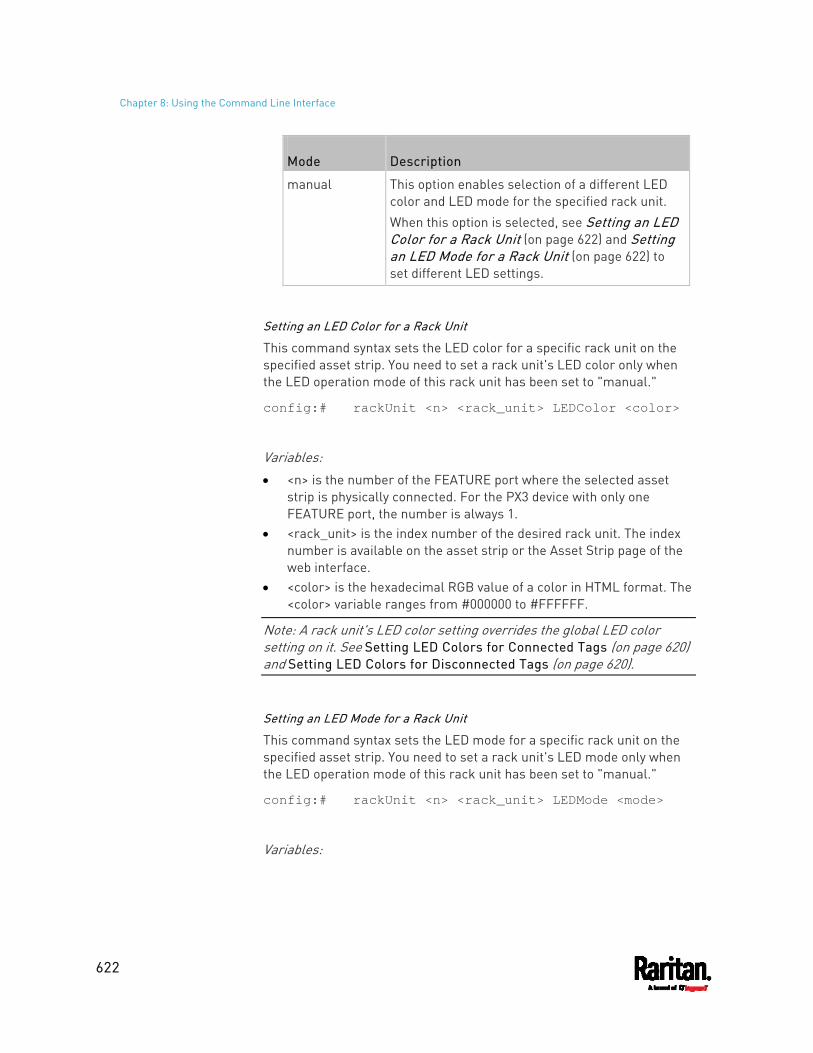
Chapter 8: Using the Command Line Interface
622
Mode Description
manual This option enables selection of a different LED color and LED mode for the specified rack unit. When this option is selected, see Setting an LED Color for a Rack Unit (on page 622) and Setting an LED Mode for a Rack Unit (on page 622) to set different LED settings.
Setting an LED Color for a Rack Unit
This command syntax sets the LED color for a specific rack unit on the specified asset strip. You need to set a rack unit's LED color only when the LED operation mode of this rack unit has been set to "manual."
config:# rackUnit <n> <rack_unit> LEDColor <color>
Variables: <n> is the number of the FEATURE port where the selected asset
strip is physically connected. For the PX3 device with only one FEATURE port, the number is always 1.
<rack_unit> is the index number of the desired rack unit. The index number is available on the asset strip or the Asset Strip page of the web interface.
<color> is the hexadecimal RGB value of a color in HTML format. The <color> variable ranges from #000000 to #FFFFFF.
Note: A rack unit's LED color setting overrides the global LED color setting on it. See Setting LED Colors for Connected Tags (on page 620) and Setting LED Colors for Disconnected Tags (on page 620).
Setting an LED Mode for a Rack Unit
This command syntax sets the LED mode for a specific rack unit on the specified asset strip. You need to set a rack unit's LED mode only when the LED operation mode of this rack unit has been set to "manual."
config:# rackUnit <n> <rack_unit> LEDMode <mode>
Variables:
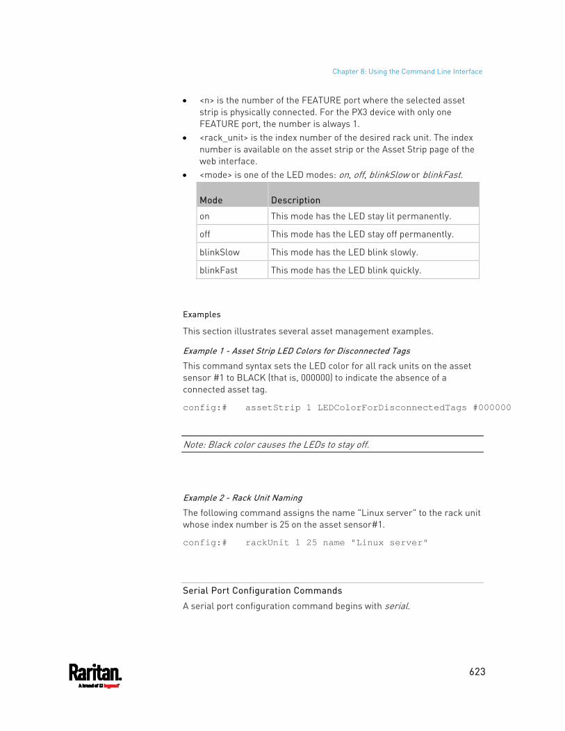
Chapter 8: Using the Command Line Interface
623
<n> is the number of the FEATURE port where the selected asset strip is physically connected. For the PX3 device with only one FEATURE port, the number is always 1.
<rack_unit> is the index number of the desired rack unit. The index number is available on the asset strip or the Asset Strip page of the web interface.
<mode> is one of the LED modes: on, off, blinkSlow or blinkFast.
Mode Description
on This mode has the LED stay lit permanently.
off This mode has the LED stay off permanently.
blinkSlow This mode has the LED blink slowly.
blinkFast This mode has the LED blink quickly.
Examples
This section illustrates several asset management examples.
Example 1 - Asset Strip LED Colors for Disconnected Tags
This command syntax sets the LED color for all rack units on the asset sensor #1 to BLACK (that is, 000000) to indicate the absence of a connected asset tag.
config:# assetStrip 1 LEDColorForDisconnectedTags #000000
Note: Black color causes the LEDs to stay off.
Example 2 - Rack Unit Naming
The following command assigns the name "Linux server" to the rack unit whose index number is 25 on the asset sensor#1.
config:# rackUnit 1 25 name "Linux server"
Serial Port Configuration Commands
A serial port configuration command begins with serial.
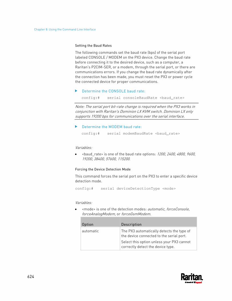
Chapter 8: Using the Command Line Interface
624
Setting the Baud Rates
The following commands set the baud rate (bps) of the serial port labeled CONSOLE / MODEM on the PX3 device. Change the baud rate before connecting it to the desired device, such as a computer, a Raritan's P2CIM-SER, or a modem, through the serial port, or there are communications errors. If you change the baud rate dynamically after the connection has been made, you must reset the PX3 or power cycle the connected device for proper communications.
Determine the CONSOLE baud rate:
config:# serial consoleBaudRate <baud_rate>
Note: The serial port bit-rate change is required when the PX3 works in conjunction with Raritan's Dominion LX KVM switch. Dominion LX only supports 19200 bps for communications over the serial interface.
Determine the MODEM baud rate:
config:# serial modemBaudRate <baud_rate>
Variables: <baud_rate> is one of the baud rate options: 1200, 2400, 4800, 9600,
19200, 38400, 57600, 115200.
Forcing the Device Detection Mode
This command forces the serial port on the PX3 to enter a specific device detection mode.
config:# serial deviceDetectionType <mode>
Variables: <mode> is one of the detection modes: automatic, forceConsole,
forceAnalogModem, or forceGsmModem.
Option Description
automatic The PX3 automatically detects the type of the device connected to the serial port. Select this option unless your PX3 cannot correctly detect the device type.
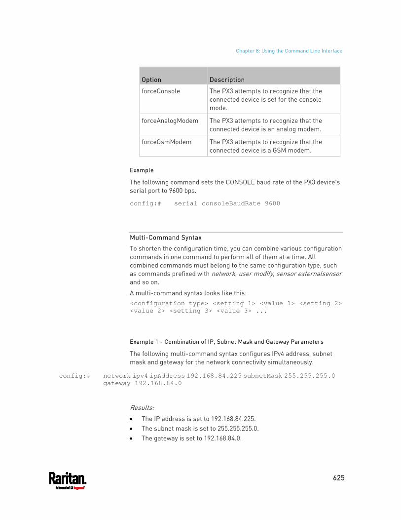
Chapter 8: Using the Command Line Interface
625
Option Description
forceConsole The PX3 attempts to recognize that the connected device is set for the console mode.
forceAnalogModem The PX3 attempts to recognize that the connected device is an analog modem.
forceGsmModem The PX3 attempts to recognize that the connected device is a GSM modem.
Example
The following command sets the CONSOLE baud rate of the PX3 device's serial port to 9600 bps.
config:# serial consoleBaudRate 9600
Multi-Command Syntax
To shorten the configuration time, you can combine various configuration commands in one command to perform all of them at a time. All combined commands must belong to the same configuration type, such as commands prefixed with network, user modify, sensor externalsensor and so on.
A multi-command syntax looks like this: <configuration type> <setting 1> <value 1> <setting 2> <value 2> <setting 3> <value 3> ...
Example 1 - Combination of IP, Subnet Mask and Gateway Parameters
The following multi-command syntax configures IPv4 address, subnet mask and gateway for the network connectivity simultaneously.
config:# network ipv4 ipAddress 192.168.84.225 subnetMask 255.255.255.0 gateway 192.168.84.0
Results: The IP address is set to 192.168.84.225. The subnet mask is set to 255.255.255.0. The gateway is set to 192.168.84.0.
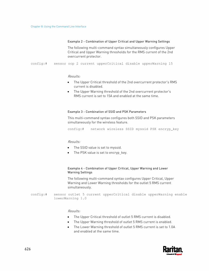
Chapter 8: Using the Command Line Interface
626
Example 2 - Combination of Upper Critical and Upper Warning Settings
The following multi-command syntax simultaneously configures Upper Critical and Upper Warning thresholds for the RMS current of the 2nd overcurrent protector.
config:# sensor ocp 2 current upperCritical disable upperWarning 15
Results: The Upper Critical threshold of the 2nd overcurrent protector's RMS
current is disabled. The Upper Warning threshold of the 2nd overcurrent protector's
RMS current is set to 15A and enabled at the same time.
Example 3 - Combination of SSID and PSK Parameters
This multi-command syntax configures both SSID and PSK parameters simultaneously for the wireless feature.
config:# network wireless SSID myssid PSK encryp_key
Results: The SSID value is set to myssid. The PSK value is set to encryp_key.
Example 4 - Combination of Upper Critical, Upper Warning and Lower Warning Settings
The following multi-command syntax configures Upper Critical, Upper Warning and Lower Warning thresholds for the outlet 5 RMS current simultaneously.
config:# sensor outlet 5 current upperCritical disable upperWarning enable lowerWarning 1.0
Results: The Upper Critical threshold of outlet 5 RMS current is disabled. The Upper Warning threshold of outlet 5 RMS current is enabled. The Lower Warning threshold of outlet 5 RMS current is set to 1.0A
and enabled at the same time.
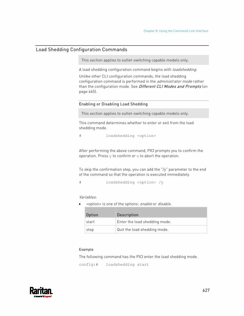
Chapter 8: Using the Command Line Interface
627
Load Shedding Configuration Commands
This section applies to outlet-switching capable models only.
A load shedding configuration command begins with loadshedding.
Unlike other CLI configuration commands, the load shedding configuration command is performed in the administrator mode rather than the configuration mode. See Different CLI Modes and Prompts (on page 465).
Enabling or Disabling Load Shedding
This section applies to outlet-switching capable models only.
This command determines whether to enter or exit from the load shedding mode.
# loadshedding <option>
After performing the above command, PX3 prompts you to confirm the operation. Press y to confirm or n to abort the operation.
To skip the confirmation step, you can add the "/y" parameter to the end of the command so that the operation is executed immediately.
# loadshedding <option> /y
Variables: <option> is one of the options: enable or disable.
Option Description
start Enter the load shedding mode.
stop Quit the load shedding mode.
Example
The following command has the PX3 enter the load shedding mode.
config:# loadshedding start
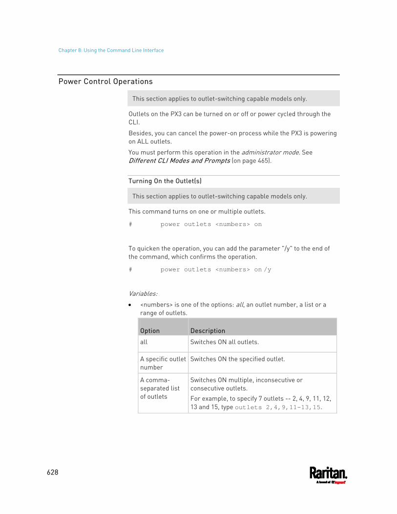
Chapter 8: Using the Command Line Interface
628
Power Control Operations
This section applies to outlet-switching capable models only.
Outlets on the PX3 can be turned on or off or power cycled through the CLI.
Besides, you can cancel the power-on process while the PX3 is powering on ALL outlets.
You must perform this operation in the administrator mode. See Different CLI Modes and Prompts (on page 465).
Turning On the Outlet(s)
This section applies to outlet-switching capable models only.
This command turns on one or multiple outlets.
# power outlets <numbers> on
To quicken the operation, you can add the parameter "/y" to the end of the command, which confirms the operation.
# power outlets <numbers> on /y
Variables: <numbers> is one of the options: all, an outlet number, a list or a
range of outlets.
Option Description
all Switches ON all outlets.
A specific outlet number
Switches ON the specified outlet.
A comma- separated list of outlets
Switches ON multiple, inconsecutive or consecutive outlets. For example, to specify 7 outlets -- 2, 4, 9, 11, 12, 13 and 15, type outlets 2,4,9,11-13,15.
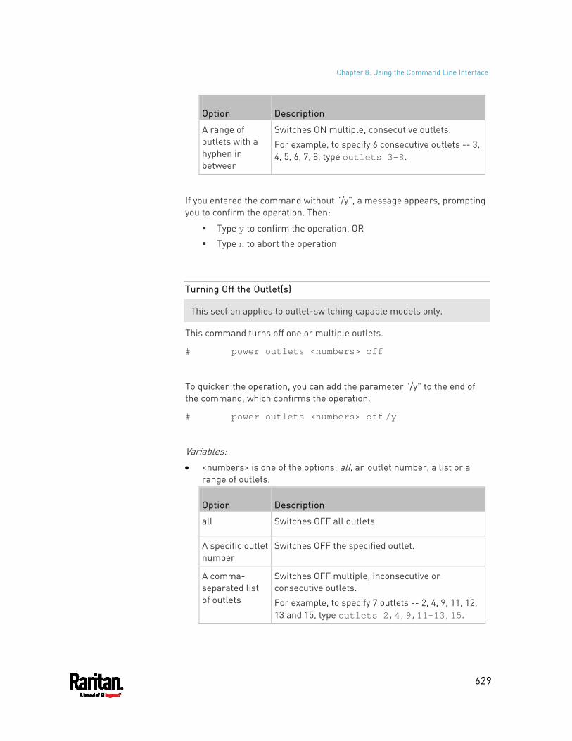
Chapter 8: Using the Command Line Interface
629
Option Description
A range of outlets with a hyphen in between
Switches ON multiple, consecutive outlets. For example, to specify 6 consecutive outlets -- 3, 4, 5, 6, 7, 8, type outlets 3-8.
If you entered the command without "/y", a message appears, prompting you to confirm the operation. Then:
Type y to confirm the operation, OR
Type n to abort the operation
Turning Off the Outlet(s)
This section applies to outlet-switching capable models only.
This command turns off one or multiple outlets.
# power outlets <numbers> off
To quicken the operation, you can add the parameter "/y" to the end of the command, which confirms the operation.
# power outlets <numbers> off /y
Variables: <numbers> is one of the options: all, an outlet number, a list or a
range of outlets.
Option Description
all Switches OFF all outlets.
A specific outlet number
Switches OFF the specified outlet.
A comma- separated list of outlets
Switches OFF multiple, inconsecutive or consecutive outlets. For example, to specify 7 outlets -- 2, 4, 9, 11, 12, 13 and 15, type outlets 2,4,9,11-13,15.
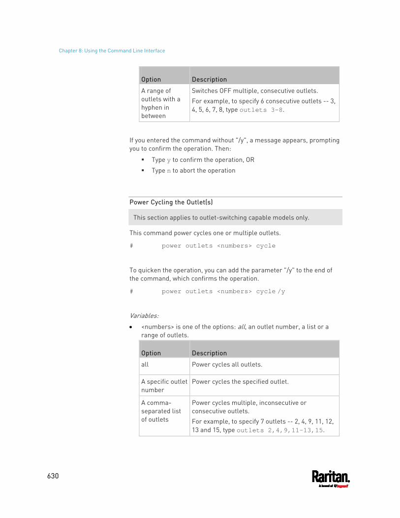
Chapter 8: Using the Command Line Interface
630
Option Description
A range of outlets with a hyphen in between
Switches OFF multiple, consecutive outlets. For example, to specify 6 consecutive outlets -- 3, 4, 5, 6, 7, 8, type outlets 3-8.
If you entered the command without "/y", a message appears, prompting you to confirm the operation. Then:
Type y to confirm the operation, OR
Type n to abort the operation
Power Cycling the Outlet(s)
This section applies to outlet-switching capable models only.
This command power cycles one or multiple outlets.
# power outlets <numbers> cycle
To quicken the operation, you can add the parameter "/y" to the end of the command, which confirms the operation.
# power outlets <numbers> cycle /y
Variables: <numbers> is one of the options: all, an outlet number, a list or a
range of outlets.
Option Description
all Power cycles all outlets.
A specific outlet number
Power cycles the specified outlet.
A comma- separated list of outlets
Power cycles multiple, inconsecutive or consecutive outlets. For example, to specify 7 outlets -- 2, 4, 9, 11, 12, 13 and 15, type outlets 2,4,9,11-13,15.
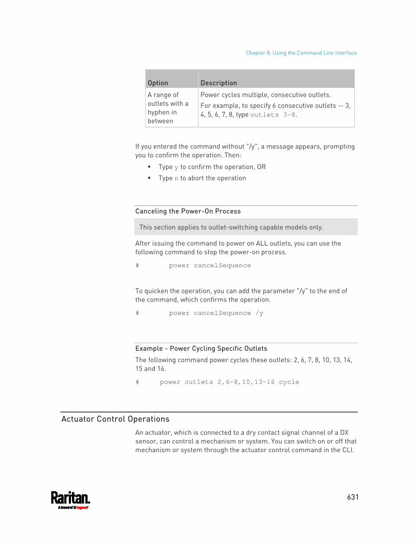
Chapter 8: Using the Command Line Interface
631
Option Description
A range of outlets with a hyphen in between
Power cycles multiple, consecutive outlets. For example, to specify 6 consecutive outlets -- 3, 4, 5, 6, 7, 8, type outlets 3-8.
If you entered the command without "/y", a message appears, prompting you to confirm the operation. Then:
Type y to confirm the operation, OR
Type n to abort the operation
Canceling the Power-On Process
This section applies to outlet-switching capable models only.
After issuing the command to power on ALL outlets, you can use the following command to stop the power-on process.
# power cancelSequence
To quicken the operation, you can add the parameter "/y" to the end of the command, which confirms the operation.
# power cancelSequence /y
Example - Power Cycling Specific Outlets
The following command power cycles these outlets: 2, 6, 7, 8, 10, 13, 14, 15 and 16.
# power outlets 2,6-8,10,13-16 cycle
Actuator Control Operations
An actuator, which is connected to a dry contact signal channel of a DX sensor, can control a mechanism or system. You can switch on or off that mechanism or system through the actuator control command in the CLI.
Chapter 8: Using the Command Line Interface
632
Perform these commands in the administrator or user mode. See Different CLI Modes and Prompts (on page 465).
Switching On an Actuator
This command syntax turns on one actuator.
# control actuator <n> on
To quicken the operation, you can add the parameter "/y" to the end of the command, which confirms the operation.
# control actuator <n> on /y
Variables: <n> is an actuator's ID number.
The ID number is available in the PX3 web interface or using the show command in the CLI. It is an integer between 1 and 32.
If you entered the command without "/y", a message appears, prompting you to confirm the operation. Then:
Type y to confirm the operation, OR
Type n to abort the operation
Switching Off an Actuator
This command syntax turns off one actuator.
# control actuator <n> off
To quicken the operation, you can add the parameter "/y" to the end of the command, which confirms the operation.
# control actuator <n> off /y
Variables: <n> is an actuator's ID number.
The ID number is available in the PX3 web interface or using the show command in the CLI. It is an integer between 1 and 32.
Chapter 8: Using the Command Line Interface
633
If you entered the command without "/y", a message appears, prompting you to confirm the operation. Then:
Type y to confirm the operation, OR
Type n to abort the operation
Example - Turning On a Specific Actuator
The following command turns on the actuator whose ID number is 8.
# control actuator 8 on
Unblocking a User
If any user is blocked from accessing the PX3, you can unblock them at the local console.
To unblock a user: 1. Log in to the CLI interface using any terminal program via a local
connection. See With HyperTerminal (on page 463).
2. When the Username prompt appears, type unblock and press Enter.
3. When the "Username to unblock" prompt appears, type the name of
the blocked user and press Enter.
4. A message appears, indicating that the specified user was unblocked
successfully.
Resetting the PX3
You can reset the PX3 to factory defaults or simply restart it using the CLI commands.
Restarting the PDU
This command restarts the PX3. It is not a factory default reset.
To restart the PX3: 1. Ensure you have entered administrator mode and the # prompt is
displayed.
Chapter 8: Using the Command Line Interface
634
2. Type either of the following commands to restart the PX3.
# reset unit
-- OR --
# reset unit /y
3. If you entered the command without "/y" in Step 2, a message appears prompting you to confirm the operation. Type y to confirm the reset.
4. Wait until the Username prompt appears, indicating the reset is complete.
Note: If you are performing this command over a USB connection, re-connect the USB cable after the reset is completed, or the CLI communications are lost.
Resetting Active Energy Readings
You can reset either one active energy sensor or all active energy sensors at a time to restart the energy accumulation process.
Only users with the "Admin" role assigned can reset active energy readings.
To reset all active energy readings of the PX3: # reset activeEnergy pdu
-- OR --
# reset activeEnergy pdu /y
To reset one inlet's active energy readings: # reset activeEnergy inlet <n>
-- OR --
# reset activeEnergy inlet <n> /y
To reset one outlet's active energy readings: # reset activeEnergy outlet <outlet_n>
-- OR --
# reset activeEnergy outlet <outlet_n> /y
To reset one outlet group's active energy readings: # reset activeEnergy outletgroup <ID>
-- OR --
Chapter 8: Using the Command Line Interface
635
# reset activeEnergy outletgroup <ID> /y
If you entered the command without "/y", a message appears prompting you to confirm the operation. Type y to confirm the reset or n to abort it.
Variables: <n> is the inlet number. <outlet_n> is an outlet number. <ID> is an outlet group's index number.
Resetting to Factory Defaults
The following commands restore all settings of the PX3 to factory defaults.
To reset PX3 settings after login, use either command: # reset factorydefaults
-- OR --
# reset factorydefaults /y
To reset PX3 settings before login: Username: factorydefaults
See Using the CLI Command (on page 718) for details.
Network Troubleshooting
The PX3 provides 4 diagnostic commands for troubleshooting network problems: nslookup, netstat, ping, and traceroute. The diagnostic commands function as corresponding Linux commands and can get corresponding Linux outputs.
Entering Diagnostic Mode
Diagnostic commands function in the diagnostic mode only.
To enter the diagnostic mode: 1. Enter either of the following modes:
Administrator mode: The # prompt is displayed. User mode: The > prompt is displayed.
2. Type diag and press Enter. The diag# or diag> prompt appears, indicating that you have entered the diagnostic mode.
3. Now you can type any diagnostic commands for troubleshooting.
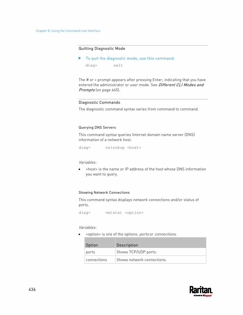
Chapter 8: Using the Command Line Interface
636
Quitting Diagnostic Mode
To quit the diagnostic mode, use this command:
diag> exit
The # or > prompt appears after pressing Enter, indicating that you have entered the administrator or user mode. See Different CLI Modes and Prompts (on page 465).
Diagnostic Commands
The diagnostic command syntax varies from command to command.
Querying DNS Servers
This command syntax queries Internet domain name server (DNS) information of a network host.
diag> nslookup <host>
Variables: <host> is the name or IP address of the host whose DNS information
you want to query.
Showing Network Connections
This command syntax displays network connections and/or status of ports.
diag> netstat <option>
Variables: <option> is one of the options: ports or connections.
Option Description
ports Shows TCP/UDP ports.
connections Shows network connections.
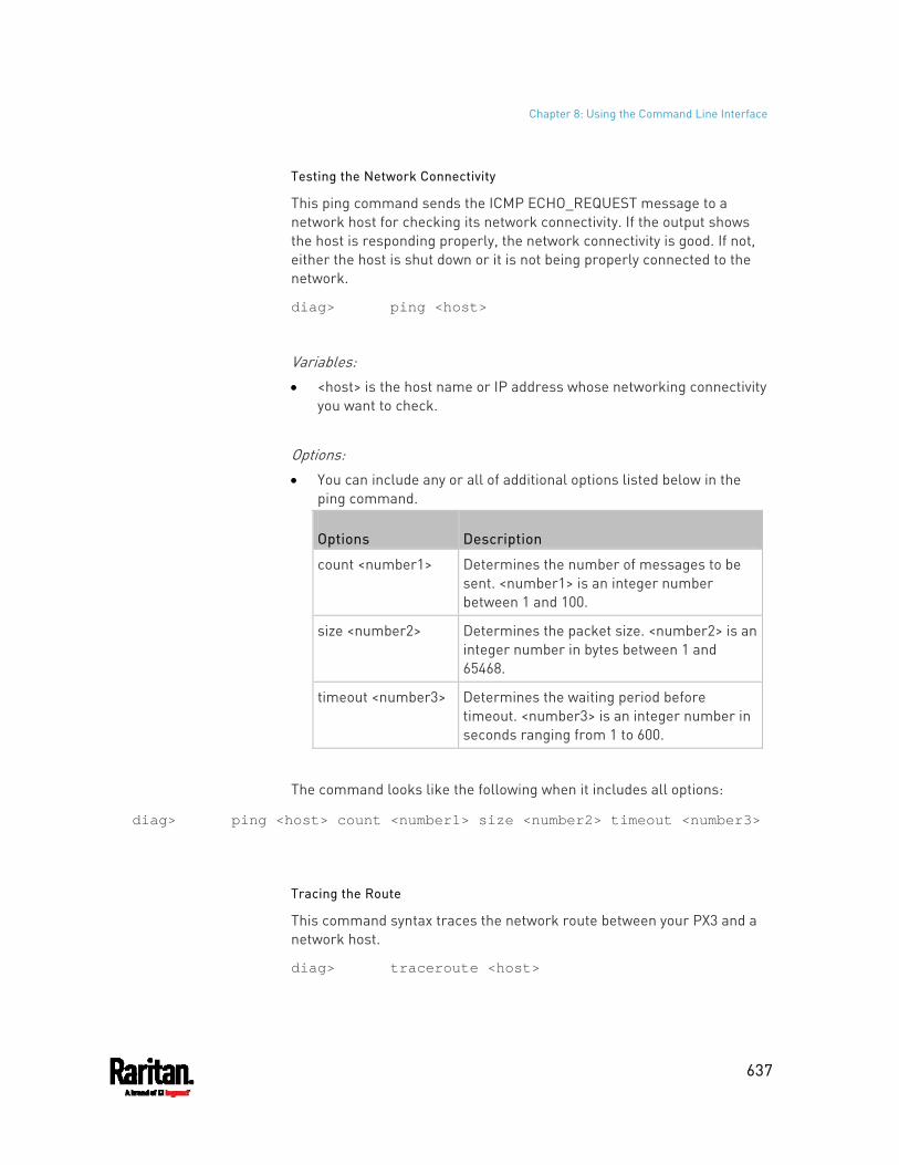
Chapter 8: Using the Command Line Interface
637
Testing the Network Connectivity
This ping command sends the ICMP ECHO_REQUEST message to a network host for checking its network connectivity. If the output shows the host is responding properly, the network connectivity is good. If not, either the host is shut down or it is not being properly connected to the network.
diag> ping <host>
Variables: <host> is the host name or IP address whose networking connectivity
you want to check.
Options: You can include any or all of additional options listed below in the
ping command.
Options Description
count <number1> Determines the number of messages to be sent. <number1> is an integer number between 1 and 100.
size <number2> Determines the packet size. <number2> is an integer number in bytes between 1 and 65468.
timeout <number3> Determines the waiting period before timeout. <number3> is an integer number in seconds ranging from 1 to 600.
The command looks like the following when it includes all options:
diag> ping <host> count <number1> size <number2> timeout <number3>
Tracing the Route
This command syntax traces the network route between your PX3 and a network host.
diag> traceroute <host>
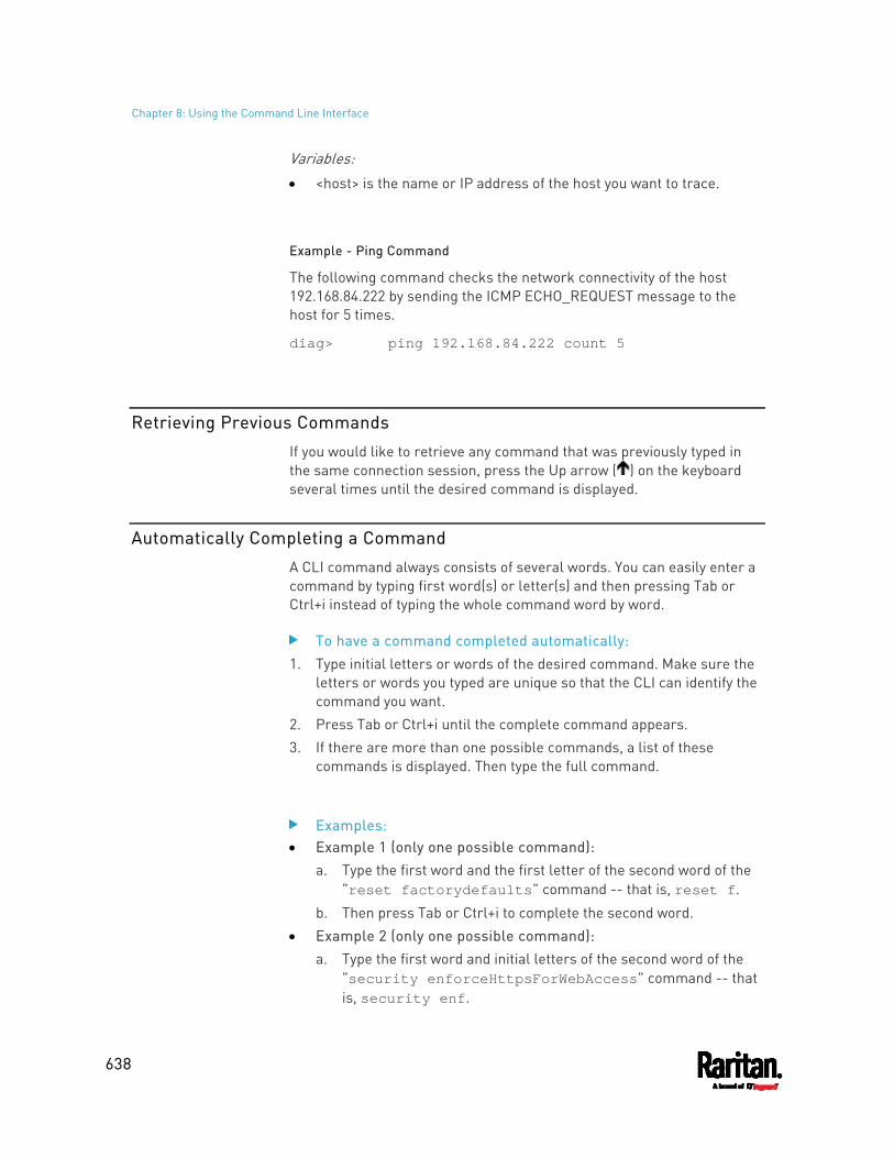
Chapter 8: Using the Command Line Interface
638
Variables: <host> is the name or IP address of the host you want to trace.
Example - Ping Command
The following command checks the network connectivity of the host 192.168.84.222 by sending the ICMP ECHO_REQUEST message to the host for 5 times.
diag> ping 192.168.84.222 count 5
Retrieving Previous Commands
If you would like to retrieve any command that was previously typed in the same connection session, press the Up arrow ( ) on the keyboard several times until the desired command is displayed.
Automatically Completing a Command
A CLI command always consists of several words. You can easily enter a command by typing first word(s) or letter(s) and then pressing Tab or Ctrl+i instead of typing the whole command word by word.
To have a command completed automatically: 1. Type initial letters or words of the desired command. Make sure the
letters or words you typed are unique so that the CLI can identify the command you want.
2. Press Tab or Ctrl+i until the complete command appears. 3. If there are more than one possible commands, a list of these
commands is displayed. Then type the full command.
Examples: Example 1 (only one possible command):
a. Type the first word and the first letter of the second word of the "reset factorydefaults" command -- that is, reset f.
b. Then press Tab or Ctrl+i to complete the second word. Example 2 (only one possible command):
a. Type the first word and initial letters of the second word of the "security enforceHttpsForWebAccess" command -- that is, security enf.
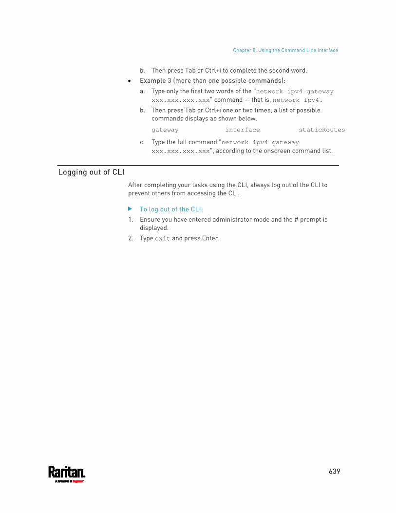
Chapter 8: Using the Command Line Interface
639
b. Then press Tab or Ctrl+i to complete the second word. Example 3 (more than one possible commands):
a. Type only the first two words of the "network ipv4 gateway xxx.xxx.xxx.xxx" command -- that is, network ipv4.
b. Then press Tab or Ctrl+i one or two times, a list of possible commands displays as shown below.
gateway interface staticRoutes
c. Type the full command "network ipv4 gateway xxx.xxx.xxx.xxx", according to the onscreen command list.
Logging out of CLI
After completing your tasks using the CLI, always log out of the CLI to prevent others from accessing the CLI.
To log out of the CLI: 1. Ensure you have entered administrator mode and the # prompt is
displayed.
2. Type exit and press Enter.
640
You can perform a Secure Copy (SCP) command to update the PX3 firmware, do bulk configuration, or back up and restore the configuration.
In This Chapter
Firmware Update via SCP ....................................................................... 640 Bulk Configuration via SCP ..................................................................... 641 Backup and Restore via SCP................................................................... 642 Downloading Diagnostic Data via SCP.................................................... 643 Uploading or Downloading Raw Configuration Data .............................. 645
Firmware Update via SCP
Same as any PX3 firmware update, all user management operations are suspended and all login attempts fail during the SCP firmware update. For details, see Updating the PX3 Firmware (on page 413).
Warning: Do NOT perform the firmware upgrade over a wireless network connection.
To update the firmware via SCP: 1. Type the following SCP command and press Enter.
scp <firmware file> <user name>@<device ip>:/fwupdate
<firmware file> is the PX3 firmware's filename. If the firmware
file is not in the current directory, you must include the path in the filename.
<user name> is the "admin" or any user profile with the Firmware Update permission.
<device ip> is the IP address or hostname of the PX3 where you want to upload the specified file.
2. Type the password when prompted, and press Enter. 3. The system transmits the specified firmware file to the PX3, and
shows the transmission speed and percentage. 4. When the transmission is complete, it shows the following message,
indicating that the PX3 starts to update its firmware now. Wait until the upgrade completes. Starting firmware update. The connection will be closed now.
Chapter 9 Using SCP Commands
Chapter 9: Using SCP Commands
641
SCP example: scp pdu-px2-030410-44599.bin [email protected]:/fwupdate
Windows PSCP command:
PSCP in Windows works in a similar way to the SCP. pscp <firmware file> <user name>@<device
ip>:/fwupdate
Bulk Configuration via SCP
Like performing bulk configuration via the web interface, there are two steps with the bulk configuration using the SCP commands:
a. Save a configuration from a source PX3. b. Copy the configuration file to one or multiple destination PX3.
For detailed information on the bulk configuration requirements, see Bulk Configuration (on page 418).
To save the configuration via SCP: 1. Type the following SCP command and press Enter.
scp <user name>@<device ip>:/bulk_config.txt
<user name> is the "admin" or any user profile with
Administrator Privileges. <device ip> is the IP address or hostname of the PX3 whose
configuration you want to save. 2. Type the user password when prompted. 3. The system saves the configuration from the PX3 to a file named
"bulk_config.txt."
To copy the configuration via SCP: 1. Type the following SCP command and press Enter.
scp bulk_config.txt <user name>@<device ip>:/bulk_restore
<user name> is the "admin" or any user profile with
Administrator Privileges <device ip> is the IP address of the PX3 whose configuration you
want to copy. 2. Type the user password when prompted.
Chapter 9: Using SCP Commands
642
3. The system copies the configuration included in the file "bulk_config.txt" to another PX3, and displays the following message. Starting restore operation. The connection will be closed now.
SCP examples: Save operation:
scp [email protected]:/bulk_config.txt
Copy operation: scp bulk_config.txt [email protected]:/bulk_restore
Windows PSCP commands:
PSCP in Windows works in a similar way to the SCP.
Save operation: pscp <user name>@<device ip>:/bulk_config.txt
Copy operation: pscp bulk_config.txt <user name>@<device ip>:/bulk_restore
Alternative of bulk configuration via SCP:
Both the methods of uploading 'bulk configuration' file or 'raw configuration' file via SCP can serve the purpose of bulk configuration. The only difference is that you can configure device-specific settings with the upload of raw configuration but not with the 'bulk configuration' file.
Uploading or Downloading Raw Configuration Data (on page 645)
Backup and Restore via SCP
To back up ALL settings of a PX3, including device-specific settings, you should perform the backup operation instead of the bulk configuration.
You can restore all settings to previous ones after a backup file is available.
To back up the settings via SCP: 1. Type the following SCP command and press Enter.
scp <user name>@<device ip>:/backup_settings.txt
<user name> is the "admin" or any user profile with
Administrator Privileges
Chapter 9: Using SCP Commands
643
<device ip> is the IP address or hostname of the PX3 whose settings you want to back up.
2. Type the user password when prompted. 3. The system saves the settings from the PX3 to a file named
"backup_settings.txt."
To restore the settings via SCP: 1. Type the following SCP command and press Enter.
scp backup_settings.txt <user name>@<device ip>:/settings_restore
<user name> is the "admin" or any user profile with
Administrator Privileges <device ip> is the IP address or hostname of the PX3 whose
settings you want to restore. 2. Type the user password when prompted. 3. The system copies the configuration included in the file
"backup_settings.txt" to the PX3, and displays the following message. Starting restore operation. The connection will be closed now.
SCP examples: Backup operation:
scp [email protected]:/backup_settings.txt
Restoration operation: scp backup_settings.txt [email protected]:/settings_restore
Windows PSCP commands:
PSCP in Windows works in a similar way to the SCP.
Backup operation: pscp <user name>@<device ip>:/backup_settings.txt
Restoration operation: pscp backup_settings.txt <user name>@<device ip>:/settings_restore
Downloading Diagnostic Data via SCP
You can download the diagnostic data via SCP.
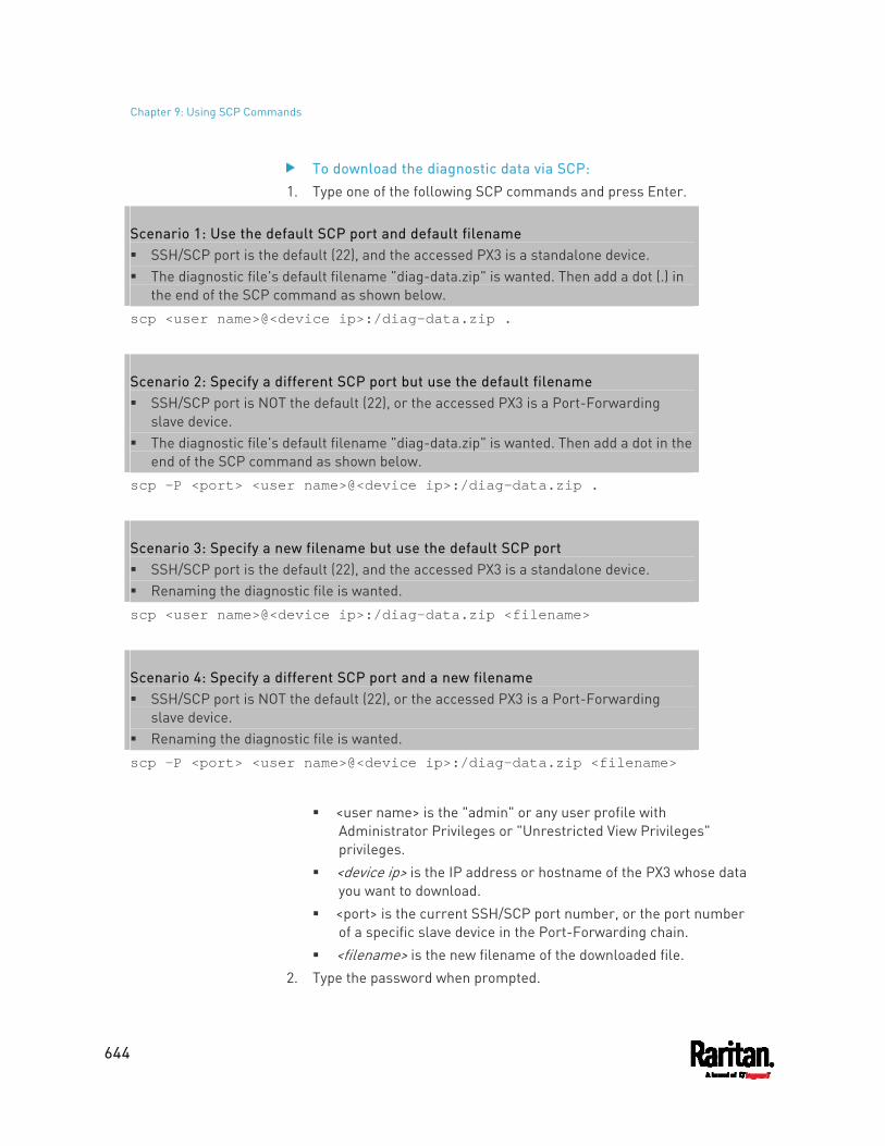
Chapter 9: Using SCP Commands
644
To download the diagnostic data via SCP: 1. Type one of the following SCP commands and press Enter.
Scenario 1: Use the default SCP port and default filename SSH/SCP port is the default (22), and the accessed PX3 is a standalone device. The diagnostic file's default filename "diag-data.zip" is wanted. Then add a dot (.) in
the end of the SCP command as shown below. scp <user name>@<device ip>:/diag-data.zip .
Scenario 2: Specify a different SCP port but use the default filename SSH/SCP port is NOT the default (22), or the accessed PX3 is a Port-Forwarding
slave device. The diagnostic file's default filename "diag-data.zip" is wanted. Then add a dot in the
end of the SCP command as shown below. scp -P <port> <user name>@<device ip>:/diag-data.zip .
Scenario 3: Specify a new filename but use the default SCP port SSH/SCP port is the default (22), and the accessed PX3 is a standalone device. Renaming the diagnostic file is wanted. scp <user name>@<device ip>:/diag-data.zip <filename>
Scenario 4: Specify a different SCP port and a new filename SSH/SCP port is NOT the default (22), or the accessed PX3 is a Port-Forwarding
slave device. Renaming the diagnostic file is wanted. scp -P <port> <user name>@<device ip>:/diag-data.zip <filename>
<user name> is the "admin" or any user profile with
Administrator Privileges or "Unrestricted View Privileges" privileges.
<device ip> is the IP address or hostname of the PX3 whose data you want to download.
<port> is the current SSH/SCP port number, or the port number of a specific slave device in the Port-Forwarding chain.
<filename> is the new filename of the downloaded file. 2. Type the password when prompted.
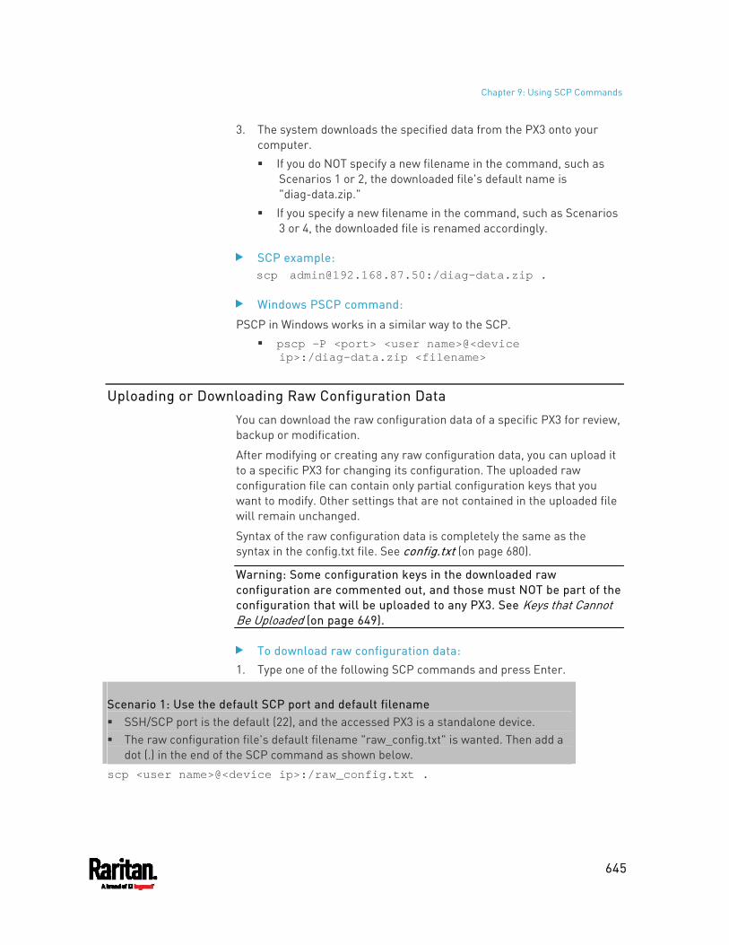
Chapter 9: Using SCP Commands
645
3. The system downloads the specified data from the PX3 onto your computer. If you do NOT specify a new filename in the command, such as
Scenarios 1 or 2, the downloaded file's default name is "diag-data.zip."
If you specify a new filename in the command, such as Scenarios 3 or 4, the downloaded file is renamed accordingly.
SCP example: scp [email protected]:/diag-data.zip .
Windows PSCP command:
PSCP in Windows works in a similar way to the SCP. pscp -P <port> <user name>@<device
ip>:/diag-data.zip <filename>
Uploading or Downloading Raw Configuration Data
You can download the raw configuration data of a specific PX3 for review, backup or modification.
After modifying or creating any raw configuration data, you can upload it to a specific PX3 for changing its configuration. The uploaded raw configuration file can contain only partial configuration keys that you want to modify. Other settings that are not contained in the uploaded file will remain unchanged.
Syntax of the raw configuration data is completely the same as the syntax in the config.txt file. See config.txt (on page 680).
Warning: Some configuration keys in the downloaded raw configuration are commented out, and those must NOT be part of the configuration that will be uploaded to any PX3. See Keys that Cannot Be Uploaded (on page 649).
To download raw configuration data: 1. Type one of the following SCP commands and press Enter.
Scenario 1: Use the default SCP port and default filename SSH/SCP port is the default (22), and the accessed PX3 is a standalone device. The raw configuration file's default filename "raw_config.txt" is wanted. Then add a
dot (.) in the end of the SCP command as shown below. scp <user name>@<device ip>:/raw_config.txt .
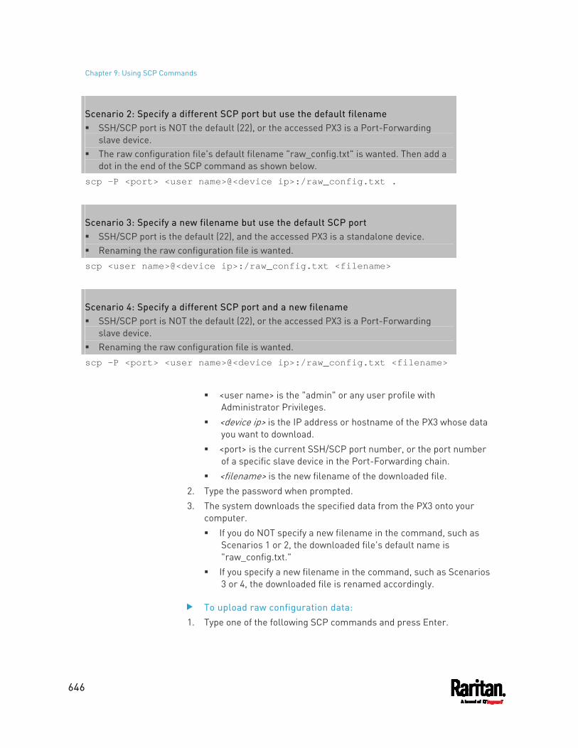
Chapter 9: Using SCP Commands
646
Scenario 2: Specify a different SCP port but use the default filename SSH/SCP port is NOT the default (22), or the accessed PX3 is a Port-Forwarding
slave device. The raw configuration file's default filename "raw_config.txt" is wanted. Then add a
dot in the end of the SCP command as shown below. scp -P <port> <user name>@<device ip>:/raw_config.txt .
Scenario 3: Specify a new filename but use the default SCP port SSH/SCP port is the default (22), and the accessed PX3 is a standalone device. Renaming the raw configuration file is wanted. scp <user name>@<device ip>:/raw_config.txt <filename>
Scenario 4: Specify a different SCP port and a new filename SSH/SCP port is NOT the default (22), or the accessed PX3 is a Port-Forwarding
slave device. Renaming the raw configuration file is wanted. scp -P <port> <user name>@<device ip>:/raw_config.txt <filename>
<user name> is the "admin" or any user profile with
Administrator Privileges. <device ip> is the IP address or hostname of the PX3 whose data
you want to download. <port> is the current SSH/SCP port number, or the port number
of a specific slave device in the Port-Forwarding chain. <filename> is the new filename of the downloaded file.
2. Type the password when prompted. 3. The system downloads the specified data from the PX3 onto your
computer. If you do NOT specify a new filename in the command, such as
Scenarios 1 or 2, the downloaded file's default name is "raw_config.txt."
If you specify a new filename in the command, such as Scenarios 3 or 4, the downloaded file is renamed accordingly.
To upload raw configuration data: 1. Type one of the following SCP commands and press Enter.
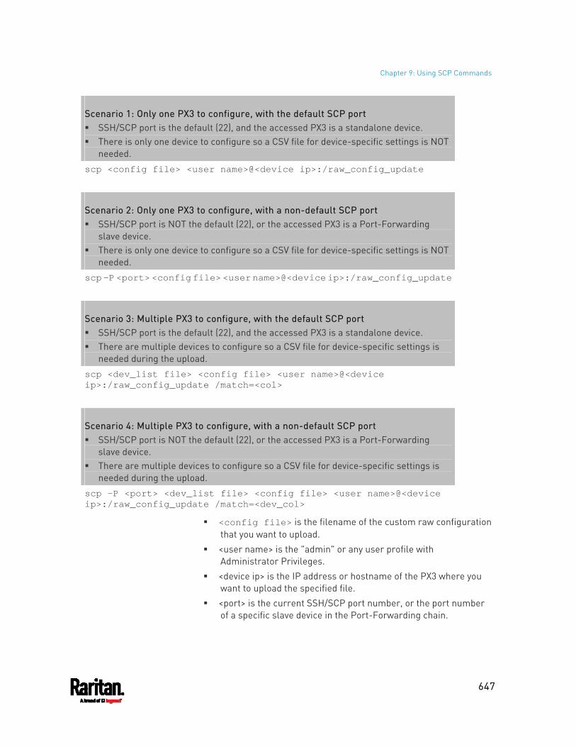
Chapter 9: Using SCP Commands
647
Scenario 1: Only one PX3 to configure, with the default SCP port SSH/SCP port is the default (22), and the accessed PX3 is a standalone device. There is only one device to configure so a CSV file for device-specific settings is NOT
needed. scp <config file> <user name>@<device ip>:/raw_config_update
Scenario 2: Only one PX3 to configure, with a non-default SCP port SSH/SCP port is NOT the default (22), or the accessed PX3 is a Port-Forwarding
slave device. There is only one device to configure so a CSV file for device-specific settings is NOT
needed. scp -P <port> <config file> <user name>@<device ip>:/raw_config_update
Scenario 3: Multiple PX3 to configure, with the default SCP port SSH/SCP port is the default (22), and the accessed PX3 is a standalone device. There are multiple devices to configure so a CSV file for device-specific settings is
needed during the upload. scp <dev_list file> <config file> <user name>@<device ip>:/raw_config_update /match=<col>
Scenario 4: Multiple PX3 to configure, with a non-default SCP port SSH/SCP port is NOT the default (22), or the accessed PX3 is a Port-Forwarding
slave device. There are multiple devices to configure so a CSV file for device-specific settings is
needed during the upload. scp -P <port> <dev_list file> <config file> <user name>@<device ip>:/raw_config_update /match=<dev_col>
<config file> is the filename of the custom raw configuration that you want to upload.
<user name> is the "admin" or any user profile with Administrator Privileges.
<device ip> is the IP address or hostname of the PX3 where you want to upload the specified file.
<port> is the current SSH/SCP port number, or the port number of a specific slave device in the Port-Forwarding chain.
Chapter 9: Using SCP Commands
648
<dev_list file> is the name of the CSV file for configuring multiple PX3 with device-specific settings. For this file's format, see devices.csv (on page 682).
For device-specific settings in the <config file>, refer each device-specific configuration key to a specific column in the <dev_list file>. See config.txt (on page 680).
<dev_col> comprises "serial:" or "mac:" and the number of the column where the serial number or MAC address of each PX3 is in the uploaded CSV file. This is the data based on which each device finds its device-specific settings. For example: If the second column contains each device's serial number,
the parameter is then serial:2.
If the seventh column contains each device's MAC address, the parameter is then mac:7.
SCP examples: Raw configuration download example --
scp [email protected]:/raw_config.txt config.txt
Raw configuration upload example with the configuration file only -- scp config.txt [email protected]:/raw_config_update
Raw configuration upload example with both configuration and device list files -- scp devices.csv config.txt [email protected]:/raw_config_update /match=serial:2
Windows PSCP commands:
PSCP in Windows works in a similar way to the SCP.
pscp -P <port> <user name>@<device ip>:/raw_config.txt <filename>
pscp -P <port> <CSV file> <config file> <user name>@<device ip>:/raw_config_update /match=<col>
Alternative of bulk configuration via SCP:
Both the methods of uploading 'bulk configuration' file or 'raw configuration' file via SCP can serve the purpose of bulk configuration. The only difference is that you can configure device-specific settings with the upload of raw configuration but not with the 'bulk configuration' file.
Bulk Configuration via SCP (on page 641)
Chapter 9: Using SCP Commands
649
Keys that Cannot Be Uploaded
The raw configuration downloaded from any PX3 contains a few configuration keys that are commented out with either syntax below.
Comment syntax Description
#INTERNAL# These keys are internal ones. They are NOT user configurable settings.
#OLD/INVALID# These keys are old or invalid ones.
Note that these configuration keys cannot be part of the configuration that you will upload to any PX3. That is, they should be either not available or they remain to be commented out in the configuration file you will upload.

650
The model name of a PX3 in-line monitor follows this format: PX3-3nnn, where n is a number, such as PX3-3411.
Unlike most of PX3 devices, each inlet of an in-line monitor is connected to an outlet only, so an inlet's rating/power data is the same as an outlet's rating/power data.
In This Chapter
Overview .................................................................................................. 650 Safety Instructions .................................................................................. 650 Flexible Cord Installation Instructions ................................................... 651 In-Line Monitor's Web Interface ............................................................. 659
Overview
An in-line monitor is implemented with the same number of inlets and outlets.
Inlets are located at the side labeled Line. Outlets are located at the side labeled Load.
An inlet is connected to a power source for receiving electricity, such as electric distribution panels or branch circuit receptacles. An outlet is connected to a device that draws power, such as a cooling or IT device.
Safety Instructions
1. Installation of this product should only be performed by a licensed electrician.
2. Make sure the line cord is disconnected from power before physically mounting or moving the location of this product.
3. This product is intended to be located in an equipment rack in an information technology room. In the United States, installation must comply and be done in accordance with NEC (2011) Article 645 Information Technology Equipment.
4. This product is designed to be used within an electronic equipment rack. The metal case of this product is electrically bonded to the line cord ground wire. A threaded grounding point on the case may be used as an additional means of protectively grounding this product and the rack.
Chapter 10 In-Line Monitors
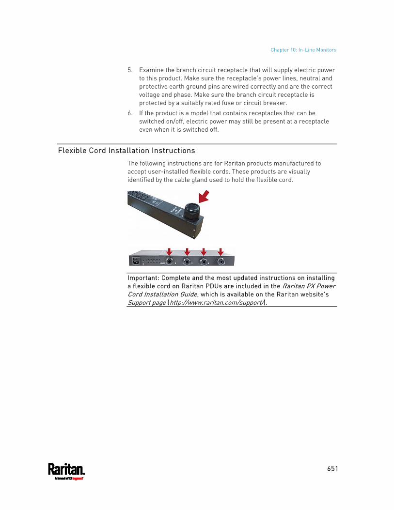
Chapter 10: In-Line Monitors
651
5. Examine the branch circuit receptacle that will supply electric power to this product. Make sure the receptacle’s power lines, neutral and protective earth ground pins are wired correctly and are the correct voltage and phase. Make sure the branch circuit receptacle is protected by a suitably rated fuse or circuit breaker.
6. If the product is a model that contains receptacles that can be switched on/off, electric power may still be present at a receptacle even when it is switched off.
Flexible Cord Installation Instructions
The following instructions are for Raritan products manufactured to accept user-installed flexible cords. These products are visually identified by the cable gland used to hold the flexible cord.
Important: Complete and the most updated instructions on installing a flexible cord on Raritan PDUs are included in the Raritan PX Power Cord Installation Guide, which is available on the Raritan website's Support page (http://www.raritan.com/support/).
Chapter 10: In-Line Monitors
652
Flexible Cord Selection The preferred flexible cable is type SOOW, 600V, 90°C or 105°C.
Consult Raritan before using a different flexible cable type. The rated ampacity of the flexible cord must be greater than or equal
to the Raritan product’s rated ampacity marked on its nameplate. In the United States, relevant ampacity ratings for flexible cords can be found in NEC(2011) section 400.5.
The number of wires in the flexible cord must match the number of terminals (including the ground terminal) inside the Raritan product. See Wiring of 3-Phase In-Line Monitors (on page 653) for exceptions.
If a plug is to be attached to the flexible cord, the length of the flexible cord must not exceed 4.5 meters - as specified in UL 60950-1 (2007) and NEC 645.5 (2011).
The flexible cord may be permanently connected to power subject to local regulatory agency approval. In the United States, relevant electrical regulations can be found in NEC (2011) sections 400.7(A)(8), 400.7(B), 368.56 and table 400.4.
Plug Selection
If a plug is to be attached to the flexible cord, the plug’s rated ampacity is chosen as follows:
In the United States, as specified in UL 60950-1, the plug’s rated ampacity must be 125% greater than the Raritan product’s rated ampacity. In some Raritan products, such as 35A 3-phase delta wired PDUs, an exactly 125% rated plug is not available. In these cases, choose the closest plug that is more than 125%. For example, a 50A plug is the closest fit for a 35A 3-phase PDU.
For all other locations, subject to local regulatory agency policy, the plug’s rated ampacity is the same as the Raritan products rated ampacity.
Receptacle Selection
For Raritan in-line monitors, any receptacle fitted to the outlet flexible cord must have identical ratings as the plug attached to the inlet flexible cord.
Derating a Raritan Product
Lower rated plugs, receptacles and flexible cords may be connected to a Raritan product. This results in a derated (reduced) ampacity rating for the product.
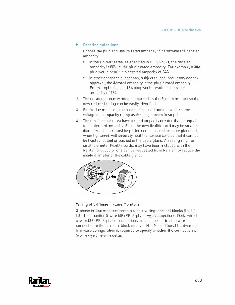
Chapter 10: In-Line Monitors
653
Derating guidelines: 1. Choose the plug and use its rated ampacity to determine the derated
ampacity. In the United States, as specified in UL 60950-1, the derated
ampacity is 80% of the plug’s rated ampacity. For example, a 30A plug would result in a derated ampacity of 24A.
In other geographic locations, subject to local regulatory agency approval, the derated ampacity is the plug’s rated ampacity. For example, using a 16A plug would result in a derated ampacity of 16A.
2. The derated ampacity must be marked on the Raritan product so the new reduced rating can be easily identified.
3. For in-line monitors, the receptacles used must have the same voltage and ampacity rating as the plug chosen in step 1.
4. The flexible cord must have a rated ampacity greater than or equal to the derated ampacity. Since the new flexible cord may be smaller diameter, a check must be performed to insure the cable gland nut, when tightened, will securely hold the flexible cord so that it cannot be twisted, pulled or pushed in the cable gland. A sealing ring, for small diameter flexible cords, may have been included with the Raritan product, or one can be requested from Raritan, to reduce the inside diameter of the cable gland.
Wiring of 3-Phase In-Line Monitors
3-phase in-line monitors contain 4-pole wiring terminal blocks (L1, L2, L3, N) to monitor 5-wire (4P+PE) 3-phase wye connections. Delta wired 4-wire (3P+PE) 3-phase connections are also permitted (no wire connected to the terminal block neutral “N”). No additional hardware or firmware configuration is required to specify whether the connection is 5-wire wye or 4-wire delta.
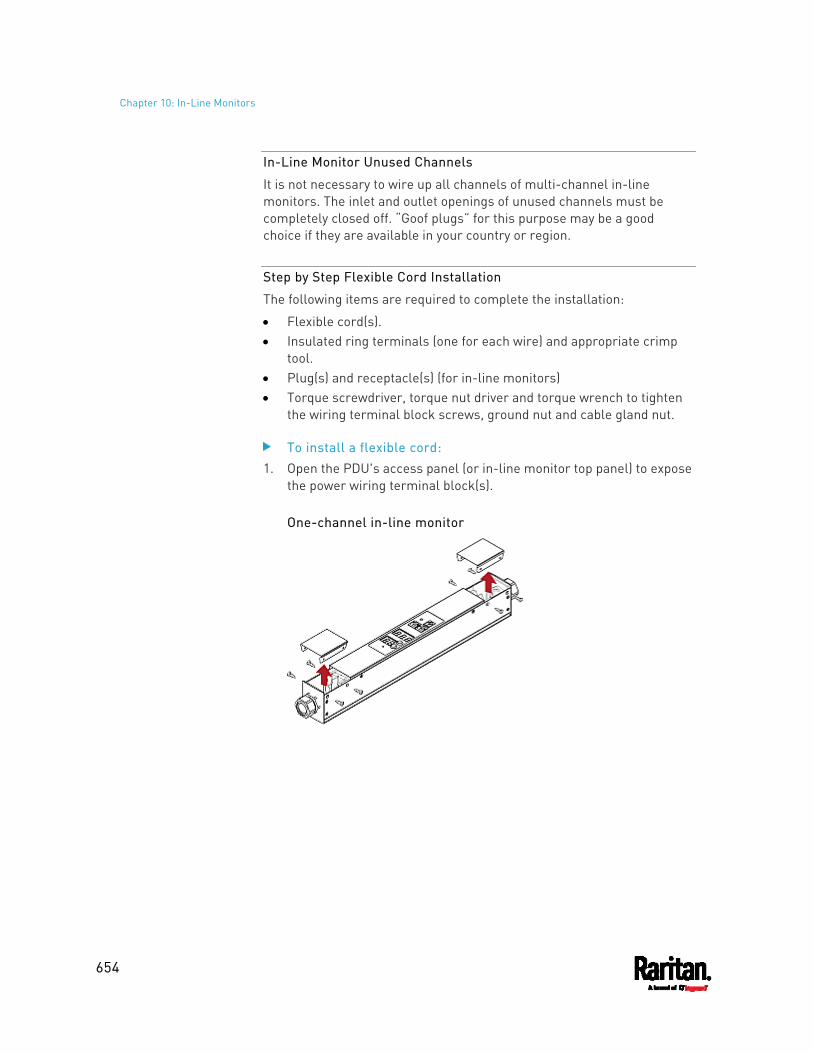
Chapter 10: In-Line Monitors
654
In-Line Monitor Unused Channels
It is not necessary to wire up all channels of multi-channel in-line monitors. The inlet and outlet openings of unused channels must be completely closed off. “Goof plugs” for this purpose may be a good choice if they are available in your country or region.
Step by Step Flexible Cord Installation
The following items are required to complete the installation:
Flexible cord(s). Insulated ring terminals (one for each wire) and appropriate crimp
tool. Plug(s) and receptacle(s) (for in-line monitors) Torque screwdriver, torque nut driver and torque wrench to tighten
the wiring terminal block screws, ground nut and cable gland nut.
To install a flexible cord: 1. Open the PDU's access panel (or in-line monitor top panel) to expose
the power wiring terminal block(s).
One-channel in-line monitor
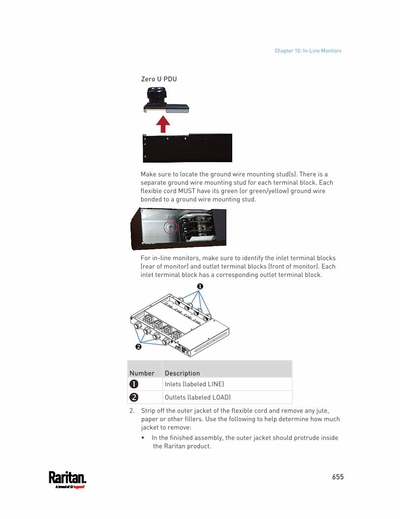
Chapter 10: In-Line Monitors
655
Zero U PDU
Make sure to locate the ground wire mounting stud(s). There is a separate ground wire mounting stud for each terminal block. Each flexible cord MUST have its green (or green/yellow) ground wire bonded to a ground wire mounting stud.
For in-line monitors, make sure to identify the inlet terminal blocks (rear of monitor) and outlet terminal blocks (front of monitor). Each inlet terminal block has a corresponding outlet terminal block.
Number Description
Inlets (labeled LINE)
Outlets (labeled LOAD)
2. Strip off the outer jacket of the flexible cord and remove any jute, paper or other fillers. Use the following to help determine how much jacket to remove: In the finished assembly, the outer jacket should protrude inside
the Raritan product.
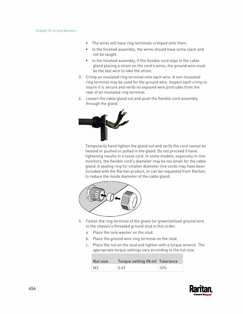
Chapter 10: In-Line Monitors
656
The wires will have ring terminals crimped onto them. In the finished assembly, the wires should have some slack and
not be taught. In the finished assembly, if the flexible cord slips in the cable
gland placing a strain on the cord’s wires, the ground wire must be the last wire to take the strain.
3. Crimp an insulated ring terminal onto each wire. A non-insulated ring terminal may be used for the ground wire. Inspect each crimp to insure it is secure and verify no exposed wire protrudes from the rear of an insulated ring terminal.
4. Loosen the cable gland nut and push the flexible cord assembly through the gland.
Temporarily hand tighten the gland nut and verify the cord cannot be twisted or pushed or pulled in the gland. Do not proceed if hand tightening results in a loose cord. In some models, especially in-line monitors, the flexible cord’s diameter may be too small for the cable gland. A sealing ring for smaller diameter line cords may have been included with the Raritan product, or can be requested from Raritan, to reduce the inside diameter of the cable gland.
5. Fasten the ring terminal of the green (or green/yellow) ground wire
to the chassis’s threaded ground stud in this order: a. Place the lock washer on the stud. b. Place the ground wire ring terminal on the stud. c. Place the nut on the stud and tighten with a torque wrench. The
appropriate torque settings vary according to the nut size.
Nut size Torque setting (N·m) Tolerance
M3 0.49 10%
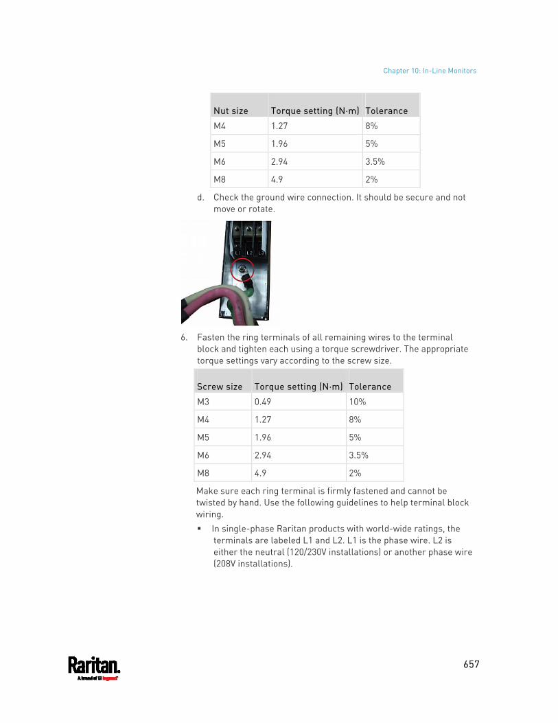
Chapter 10: In-Line Monitors
657
Nut size Torque setting (N·m) Tolerance
M4 1.27 8%
M5 1.96 5%
M6 2.94 3.5%
M8 4.9 2%
d. Check the ground wire connection. It should be secure and not move or rotate.
6. Fasten the ring terminals of all remaining wires to the terminal
block and tighten each using a torque screwdriver. The appropriate torque settings vary according to the screw size.
Screw size Torque setting (N·m) Tolerance
M3 0.49 10%
M4 1.27 8%
M5 1.96 5%
M6 2.94 3.5%
M8 4.9 2%
Make sure each ring terminal is firmly fastened and cannot be twisted by hand. Use the following guidelines to help terminal block wiring. In single-phase Raritan products with world-wide ratings, the
terminals are labeled L1 and L2. L1 is the phase wire. L2 is either the neutral (120/230V installations) or another phase wire (208V installations).
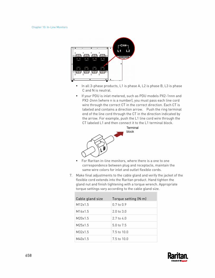
Chapter 10: In-Line Monitors
658
In all 3-phase products, L1 is phase A, L2 is phase B, L3 is phase
C and N is neutral. If your PDU is inlet metered, such as PDU models PX2-1nnn and
PX2-2nnn (where n is a number), you must pass each line cord wire through the correct CT in the correct direction. Each CT is labeled and contains a direction arrow. Push the ring terminal end of the line cord through the CT in the direction indicated by the arrow. For example, push the L1 line cord wire through the CT labeled L1 and then connect it to the L1 terminal block.
For Raritan in-line monitors, where there is a one to one
correspondence between plug and receptacle, maintain the same wire colors for inlet and outlet flexible cords.
7. Make final adjustments to the cable gland and verify the jacket of the flexible cord extends into the Raritan product. Hand tighten the gland nut and finish tightening with a torque wrench. Appropriate torque settings vary according to the cable gland size.
Cable gland size Torque setting (N·m)
M12x1.5 0.7 to 0.9
M16x1.5 2.0 to 3.0
M20x1.5 2.7 to 4.0
M25x1.5 5.0 to 7.5
M32x1.5 7.5 to 10.0
M40x1.5 7.5 to 10.0
Chapter 10: In-Line Monitors
659
Cable gland size Torque setting (N·m)
M50x1.5 7.5 to 10.0
M63x1.5 7.5 to 10.0
Note: The cable gland size is marked on the cable gland body.
After tightening, examine the flexible cord and cable gland for the following: Make sure you can see a few remaining threads between the
cable gland body and cable gland nut. The gland nut must not bottom out on the gland body.
Make sure the flexible cord does not move in the cable gland when it is twisted, pushed or pulled.
8. Re-install the PDU wiring access panel or in-line monitor cover plate. This completes internal wiring of the Raritan product.
9. For in-line monitors, fasten the receptacles to the outlet flexible cords following the manufacturer’s instructions.
10. Complete the wiring of the inlet flexible cord by performing one of these steps: Assemble the plug following the manufacturer’s instructions. Permanently attach and strain relief the flexible cord to a
junction box following applicable electrical codes.
In-Line Monitor's Web Interface
An in-line monitor's web interface is similar to a regular PX3 model's web interface.
See Using the Web Interface (on page 133) for login instructions and additional information.
Dashboard Page
An in-line monitor's Dashboard page looks slightly different from a regular PX3 device's Dashboard page.
Note: Depending on your model, elements shown on your page may appear slightly different from this image.
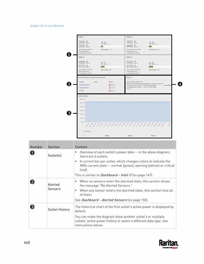
Chapter 10: In-Line Monitors
660
Number Section Content
Outlet(s) Overview of each outlet's power data -- in the above diagram,
there are 4 outlets. A current bar per outlet, which changes colors to indicate the
RMS current state -- normal (green), warning (yellow) or critical (red).
This is similar to Dashboard - Inlet I1 (on page 147).
Alerted Sensors
When no sensors enter the alarmed state, this section shows the message "No Alerted Sensors."
When any sensor enters the alarmed state, this section lists all of them.
See Dashboard - Alerted Sensors (on page 150).
Outlet History The historical chart of the first outlet's active power is displayed by default.
You can make the diagram show another outlet's or multiple outlets' active power history or select a different data type. See instructions below.
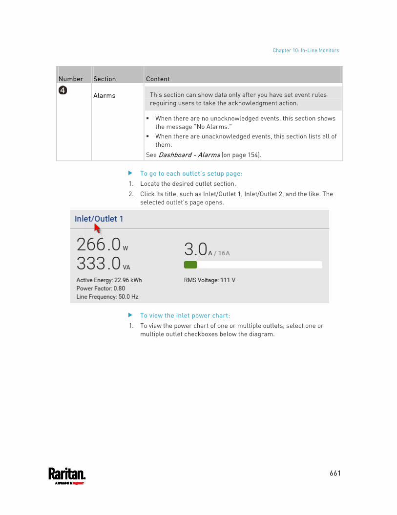
Chapter 10: In-Line Monitors
661
Number Section Content
Alarms This section can show data only after you have set event rules requiring users to take the acknowledgment action.
When there are no unacknowledged events, this section shows the message "No Alarms."
When there are unacknowledged events, this section lists all of them.
See Dashboard - Alarms (on page 154).
To go to each outlet's setup page: 1. Locate the desired outlet section. 2. Click its title, such as Inlet/Outlet 1, Inlet/Outlet 2, and the like. The
selected outlet's page opens.
To view the inlet power chart: 1. To view the power chart of one or multiple outlets, select one or
multiple outlet checkboxes below the diagram.
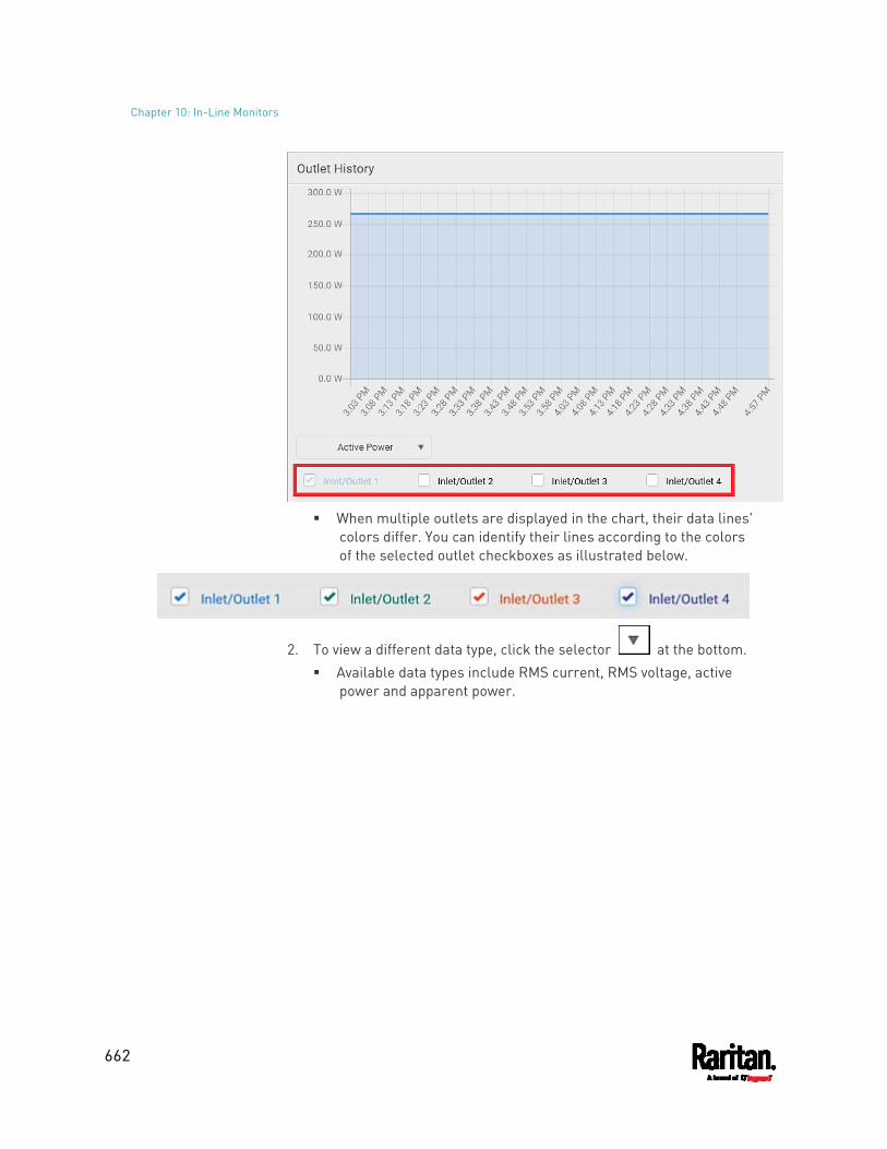
Chapter 10: In-Line Monitors
662
When multiple outlets are displayed in the chart, their data lines'
colors differ. You can identify their lines according to the colors of the selected outlet checkboxes as illustrated below.
2. To view a different data type, click the selector at the bottom. Available data types include RMS current, RMS voltage, active
power and apparent power.
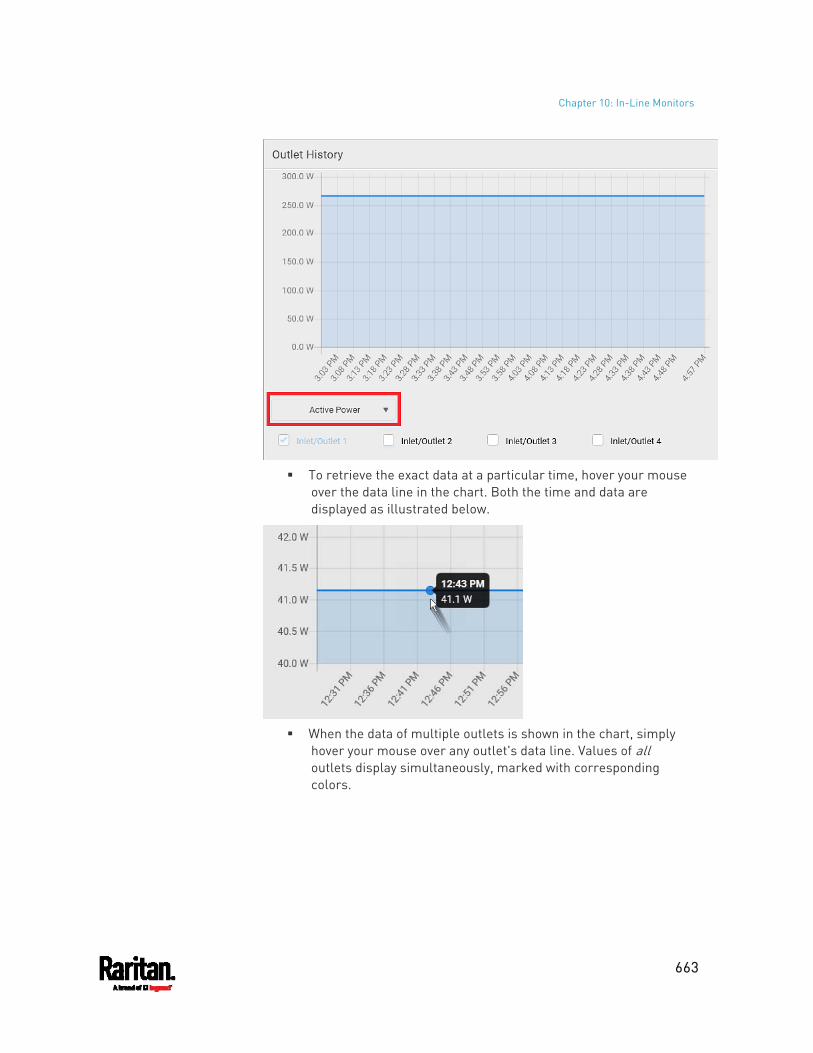
Chapter 10: In-Line Monitors
663
To retrieve the exact data at a particular time, hover your mouse
over the data line in the chart. Both the time and data are displayed as illustrated below.
When the data of multiple outlets is shown in the chart, simply
hover your mouse over any outlet's data line. Values of all outlets display simultaneously, marked with corresponding colors.
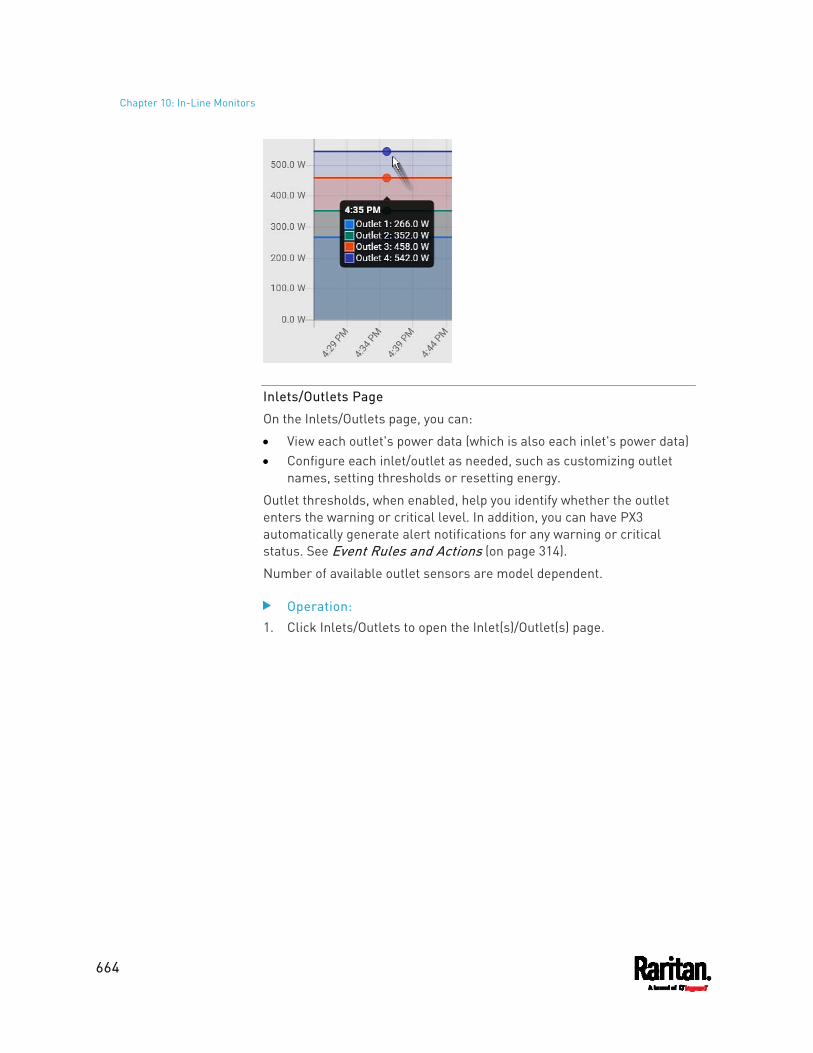
Chapter 10: In-Line Monitors
664
Inlets/Outlets Page
On the Inlets/Outlets page, you can:
View each outlet's power data (which is also each inlet's power data) Configure each inlet/outlet as needed, such as customizing outlet
names, setting thresholds or resetting energy.
Outlet thresholds, when enabled, help you identify whether the outlet enters the warning or critical level. In addition, you can have PX3 automatically generate alert notifications for any warning or critical status. See Event Rules and Actions (on page 314).
Number of available outlet sensors are model dependent.
Operation: 1. Click Inlets/Outlets to open the Inlet(s)/Outlet(s) page.
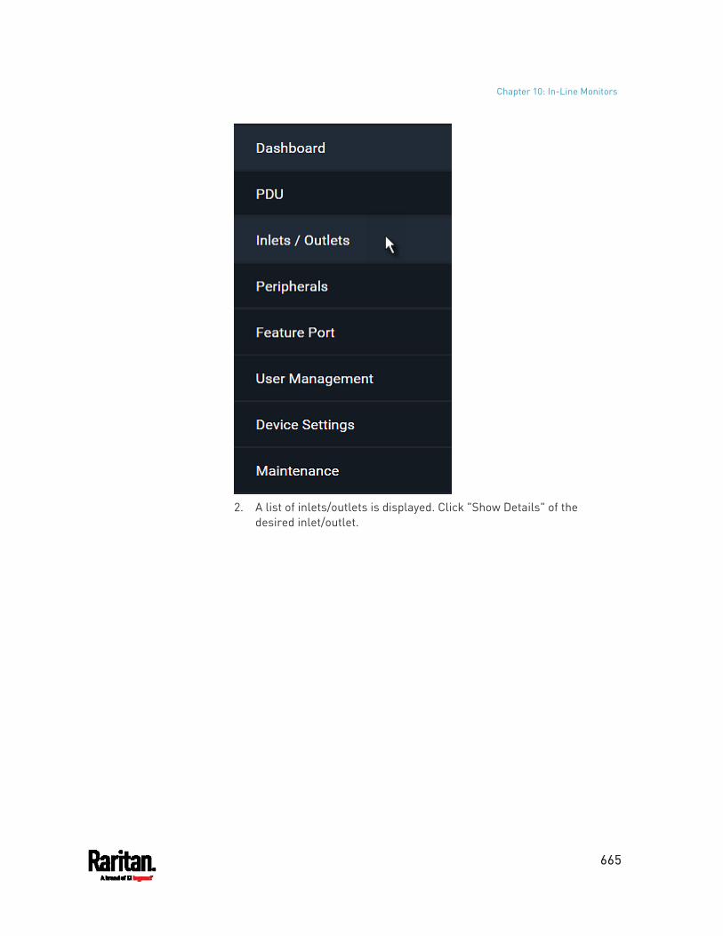
Chapter 10: In-Line Monitors
665
2. A list of inlets/outlets is displayed. Click "Show Details" of the
desired inlet/outlet.
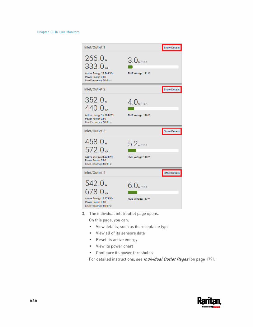
Chapter 10: In-Line Monitors
666
3. The individual inlet/outlet page opens.
On this page, you can: View details, such as its receptacle type View all of its sensors data Reset its active energy View its power chart Configure its power thresholds For detailed instructions, see Individual Outlet Pages (on page 179).
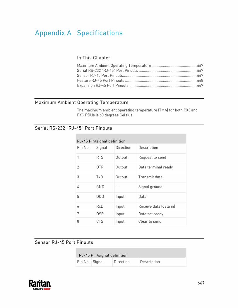
667
In This Chapter
Maximum Ambient Operating Temperature........................................... 667 Serial RS-232 "RJ-45" Port Pinouts ....................................................... 667 Sensor RJ-45 Port Pinouts...................................................................... 667 Feature RJ-45 Port Pinouts .................................................................... 668 Expansion RJ-45 Port Pinouts ................................................................ 669
Maximum Ambient Operating Temperature
The maximum ambient operating temperature (TMA) for both PX3 and PXC PDUs is 60 degrees Celsius.
Serial RS-232 "RJ-45" Port Pinouts
RJ-45 Pin/signal definition
Pin No. Signal Direction Description
1 RTS Output Request to send
2 DTR Output Data terminal ready
3 TxD Output Transmit data
4 GND ― Signal ground
5 DCD Input Data
6 RxD Input Receive data (data in)
7 DSR Input Data set ready
8 CTS Input Clear to send
Sensor RJ-45 Port Pinouts
RJ-45 Pin/signal definition
Pin No. Signal Direction Description
Appendix A Specifications
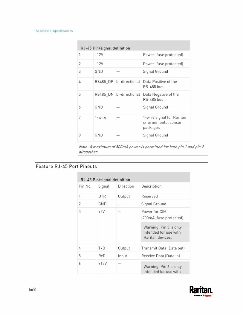
Appendix A: Specifications
668
RJ-45 Pin/signal definition
1 +12V ― Power (fuse protected)
2 +12V ― Power (fuse protected)
3 GND ― Signal Ground
4 RS485_DP bi-directional Data Positive of the RS-485 bus
5 RS485_DN bi-directional Data Negative of the RS-485 bus
6 GND ― Signal Ground
7 1-wire ― 1-wire signal for Raritan environmental sensor packages
8 GND ― Signal Ground
Note: A maximum of 500mA power is permitted for both pin 1 and pin 2 altogether.
Feature RJ-45 Port Pinouts
RJ-45 Pin/signal definition
Pin No. Signal Direction Description
1 DTR Output Reserved
2 GND ― Signal Ground
3 +5V ― Power for CIM (200mA, fuse protected)
Warning: Pin 3 is only intended for use with Raritan devices.
4 TxD Output Transmit Data (Data out)
5 RxD Input Receive Data (Data in)
6 +12V ― Warning: Pin 6 is only intended for use with
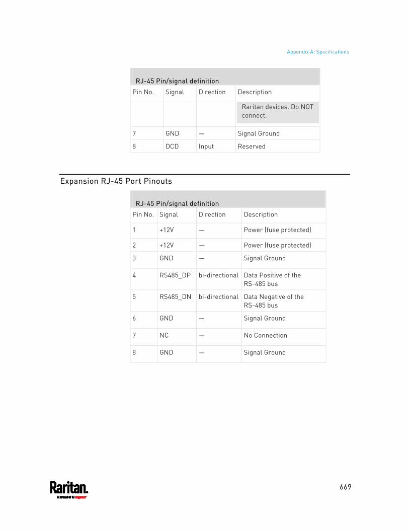
Appendix A: Specifications
669
RJ-45 Pin/signal definition
Pin No. Signal Direction Description
Raritan devices. Do NOT connect.
7 GND ― Signal Ground
8 DCD Input Reserved
Expansion RJ-45 Port Pinouts
RJ-45 Pin/signal definition
Pin No. Signal Direction Description
1 +12V ― Power (fuse protected)
2 +12V ― Power (fuse protected)
3 GND ― Signal Ground
4 RS485_DP bi-directional Data Positive of the RS-485 bus
5 RS485_DN bi-directional Data Negative of the RS-485 bus
6 GND ― Signal Ground
7 NC ― No Connection
8 GND ― Signal Ground

670
PX3 Series Model ____________
PX3 Series Serial Number ____________
OUTLET 1
OUTLET 2 OUTLET 3
MODEL
MODEL MODEL
SERIAL NUMBER
SERIAL NUMBER SERIAL NUMBER
USE
USE USE
OUTLET 4
OUTLET 5 OUTLET 6
MODEL
MODEL MODEL
SERIAL NUMBER
SERIAL NUMBER SERIAL NUMBER
USE
USE USE
OUTLET 7
OUTLET 8 OUTLET 9
MODEL
MODEL MODEL
SERIAL NUMBER
SERIAL NUMBER SERIAL NUMBER
USE
USE USE
OUTLET 10 OUTLET 11 OUTLET 12
Appendix B Equipment Setup Worksheet

Appendix B: Equipment Setup Worksheet
671
MODEL
MODEL MODEL
SERIAL NUMBER
SERIAL NUMBER SERIAL NUMBER
USE
USE USE
OUTLET 13
OUTLET 14 OUTLET 15
MODEL
MODEL MODEL
SERIAL NUMBER
SERIAL NUMBER SERIAL NUMBER
USE
USE USE
OUTLET 16
OUTLET 17 OUTLET 18
MODEL
MODEL MODEL
SERIAL NUMBER
SERIAL NUMBER SERIAL NUMBER
USE
USE USE
OUTLET 19
OUTLET 20 OUTLET 21
MODEL
MODEL MODEL
SERIAL NUMBER
SERIAL NUMBER SERIAL NUMBER
USE
USE USE
OUTLET 22 OUTLET 23 OUTLET 24
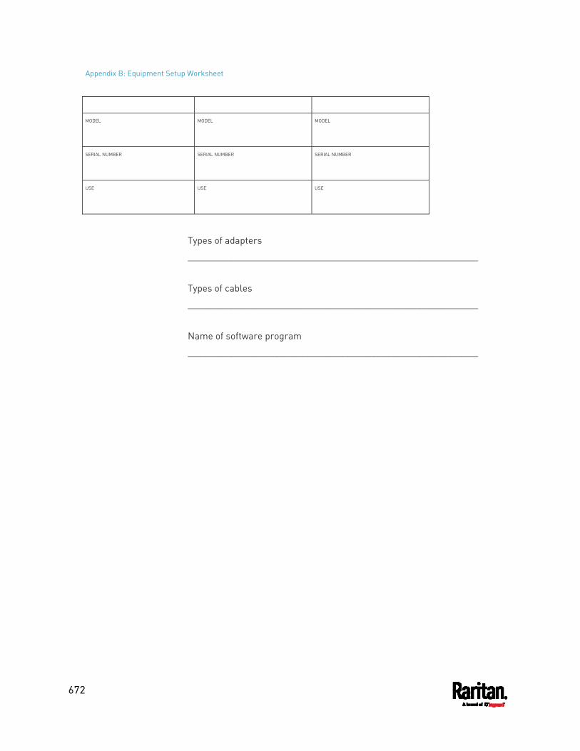
Appendix B: Equipment Setup Worksheet
672
MODEL
MODEL MODEL
SERIAL NUMBER
SERIAL NUMBER SERIAL NUMBER
USE
USE USE
Types of adapters
_________________________________________________________
Types of cables
_________________________________________________________
Name of software program
_________________________________________________________
673
You can accomplish part or all of the following tasks simultaneously by plugging a USB flash drive which contains one or several special configuration files into the PX3.
Configuration changes Firmware upgrade Downloading diagnostic data
Tip: You can also accomplish the same tasks via the TFTP server in a DHCP network. See Bulk Configuration or Firmware Upgrade via DHCP/TFTP (on page 688).
In This Chapter
Device Configuration/Upgrade Procedure.............................................. 673 System and USB Requirements.............................................................. 674 Configuration Files .................................................................................. 675 Firmware Upgrade via USB..................................................................... 686
Device Configuration/Upgrade Procedure
As of version 3.5.0, any firmware downgrade using "fwupdate.cfg" is NOT supported by default. Only firmware upgrade is permitted with "fwupdate.cfg". A special parameter is required to permit firmware downgrade via "fwupdate.cfg". See fwupdate.cfg (on page 675).
Therefore, firmware downgrade via USB is disallowed by default since release 3.5.0.
You can use one USB drive to configure or upgrade multiple PX3 devices one by one as long as it contains valid configuration files.
To use a USB drive to configure the PX3 or upgrade firmware: 1. Verify that both the USB drive and your PX3 meet the requirements.
See System and USB Requirements (on page 674). 2. Prepare required configuration files. See Configuration Files (on
page 675). 3. Copy required configuration files to the root directory of the USB
drive. For firmware upgrade, an appropriate firmware binary file is also
required.
Appendix C Configuration or Firmware Upgrade with a USB Drive
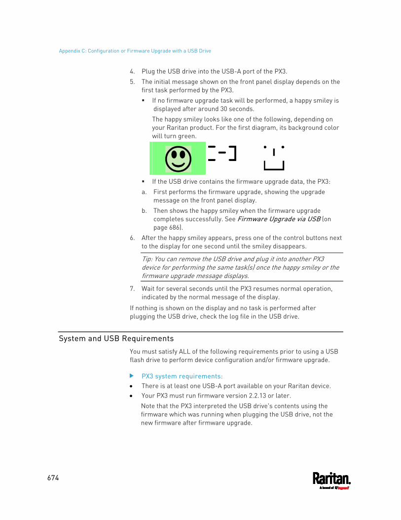
Appendix C: Configuration or Firmware Upgrade with a USB Drive
674
4. Plug the USB drive into the USB-A port of the PX3. 5. The initial message shown on the front panel display depends on the
first task performed by the PX3. If no firmware upgrade task will be performed, a happy smiley is
displayed after around 30 seconds. The happy smiley looks like one of the following, depending on your Raritan product. For the first diagram, its background color will turn green.
If the USB drive contains the firmware upgrade data, the PX3: a. First performs the firmware upgrade, showing the upgrade
message on the front panel display. b. Then shows the happy smiley when the firmware upgrade
completes successfully. See Firmware Upgrade via USB (on page 686).
6. After the happy smiley appears, press one of the control buttons next to the display for one second until the smiley disappears.
Tip: You can remove the USB drive and plug it into another PX3 device for performing the same task(s) once the happy smiley or the firmware upgrade message displays.
7. Wait for several seconds until the PX3 resumes normal operation, indicated by the normal message of the display.
If nothing is shown on the display and no task is performed after plugging the USB drive, check the log file in the USB drive.
System and USB Requirements
You must satisfy ALL of the following requirements prior to using a USB flash drive to perform device configuration and/or firmware upgrade.
PX3 system requirements: There is at least one USB-A port available on your Raritan device. Your PX3 must run firmware version 2.2.13 or later.
Note that the PX3 interpreted the USB drive's contents using the firmware which was running when plugging the USB drive, not the new firmware after firmware upgrade.
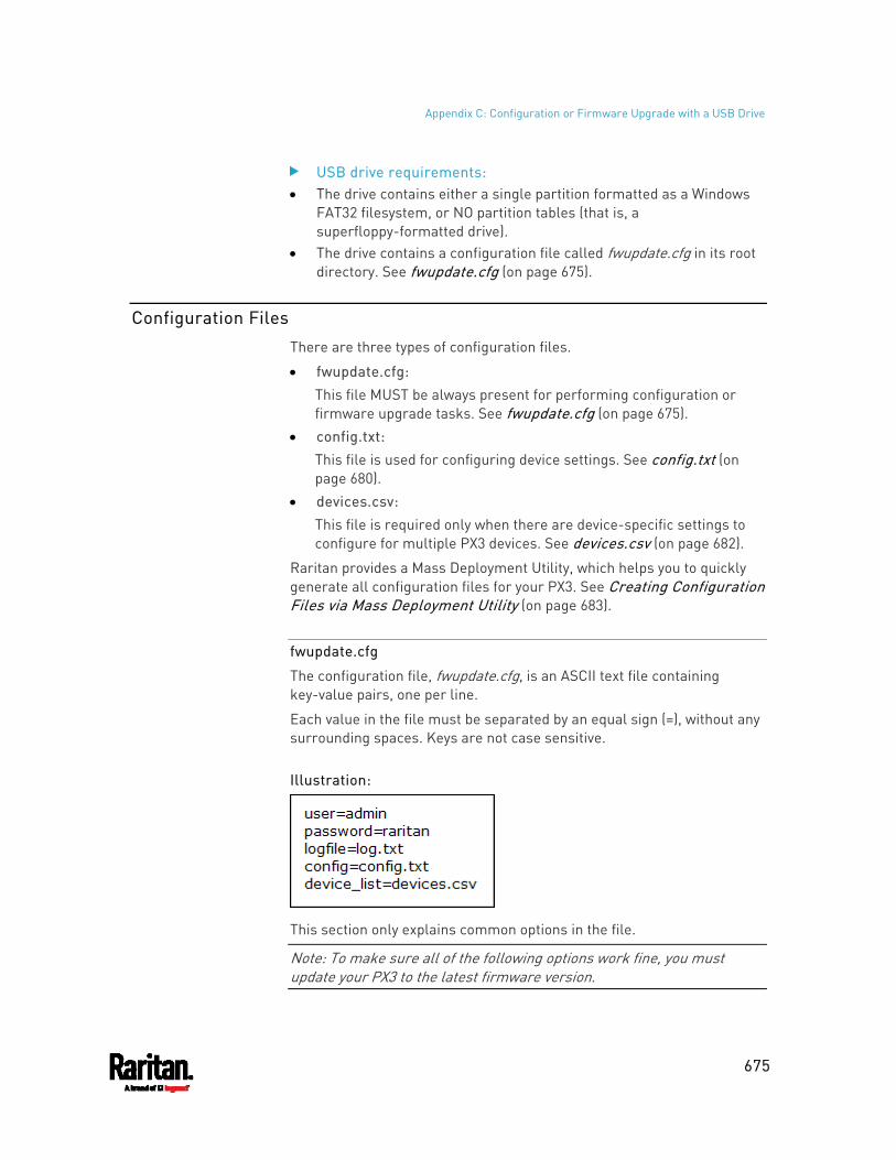
Appendix C: Configuration or Firmware Upgrade with a USB Drive
675
USB drive requirements: The drive contains either a single partition formatted as a Windows
FAT32 filesystem, or NO partition tables (that is, a superfloppy-formatted drive).
The drive contains a configuration file called fwupdate.cfg in its root directory. See fwupdate.cfg (on page 675).
Configuration Files
There are three types of configuration files.
fwupdate.cfg: This file MUST be always present for performing configuration or firmware upgrade tasks. See fwupdate.cfg (on page 675).
config.txt: This file is used for configuring device settings. See config.txt (on page 680).
devices.csv: This file is required only when there are device-specific settings to configure for multiple PX3 devices. See devices.csv (on page 682).
Raritan provides a Mass Deployment Utility, which helps you to quickly generate all configuration files for your PX3. See Creating Configuration Files via Mass Deployment Utility (on page 683).
fwupdate.cfg
The configuration file, fwupdate.cfg, is an ASCII text file containing key-value pairs, one per line.
Each value in the file must be separated by an equal sign (=), without any surrounding spaces. Keys are not case sensitive.
Illustration:
This section only explains common options in the file.
Note: To make sure all of the following options work fine, you must update your PX3 to the latest firmware version.
Appendix C: Configuration or Firmware Upgrade with a USB Drive
676
user A required option. Specify the name of a user account with Administrator Privileges. For PX3 with factory default configuration, set this option to admin.
password A required option. Specify the password of the specified admin user. For PX3 with factory default configuration, set this option to
raritan.
Tip: As of release 3.5.0, you can add multiple user credentials to fwupdate.cfg. Each 'user' line must be immediately followed by its 'password' line. PX3 will authenticate listed user credentials one by one until one of them succeeds, or until all user credentials fail.
Appendix C: Configuration or Firmware Upgrade with a USB Drive
677
logfile Specify the name of a text file where the PX3 will append the log
messages when interpreting the USB drive contents. If the specified file does not exist in the USB drive, it will be
automatically created. If this option is not set, no log messages are recorded. The
disadvantage is that no feedback is available if the PX3 detects a problem with the USB drive contents.
firmware Specify the name of a firmware binary file used to upgrade your PX3. The specified firmware file must be compatible with your PX3 and
have an official Raritan signature. If the specified firmware file is the same as the current firmware
version of your PX3, no firmware upgrade is performed. As of version 3.5.0, the default is to NOT permit any firmware
downgrade via USB on Raritan power products with "USB-A" port(s). To do this, the parameter "allow_downgrade" must be present and properly set in the fwupdate.cfg file.
config Specify the name of the configuration file containing device settings. The suggested filename is config.txt. See config.txt (on page 680).
device_list Specify the name of the configuration file listing all PX3 devices to
configure and their device-specific settings. This file is required if any macros are used in the device
configuration file "config.txt." The suggested filename is devices.csv. See devices.csv (on page
682).
match Specify a match condition for identifying a line or one PX3 device in
the device configuration file "devices.csv." The option's value comprises one word and one number as explained below: The word prior to the colon is an identification property, which is
either serial for serial number or mac for MAC address.
The number following the colon indicates a column in the devices.csv file.
Appendix C: Configuration or Firmware Upgrade with a USB Drive
678
For example, mac:7 instructs the PX3 to search for the MAC address in the 7th column of the "devices.csv" file.
The default value is serial:1, making the PX3 search for its serial number in the first column.
This option is used only if the "device_list" option has been set.
factory_reset If this option is set to true, the PX3 will be reset to factory defaults. If the device configuration will be updated at the same time, the
factory reset will be executed before updating the device configuration.
bulk_config_restore Specify the name of the bulk configuration file used to configure or
restore the PX3.
Note: See Bulk Configuration (on page 418) for instructions on generating a bulk configuration file.
Additional configuration keys set via the config.txt file will be applied after performing the bulk restore operation.
This option CANNOT be used with the option "full_config_restore." If a firmware upgrade will be performed at the same time, you must
generate the bulk configuration file based on the NEW firmware version instead of the current firmware version.
full_config_restore Specify the name of the full configuration backup file used to restore
the PX3.
Note: See Backup and Restore of Device Settings (on page 425) for instructions on generating the full configuration backup file.
Additional configuration keys set via the config.txt file will be applied after performing the configuration restore operation.
This option CANNOT be used with the option "bulk_config_restore." If a firmware upgrade will be performed at the same time, you must
generate the full configuration backup file based on the NEW firmware version instead of the current firmware version.
collect_diag If this option is set to true, the diagnostic data of the PX3 is
transmitted to the USB drive. The filename of the diagnostic data written into the USB drive is:
diag_<unit-serial>.zip
Appendix C: Configuration or Firmware Upgrade with a USB Drive
679
The PX3 device beeps after it finishes writing the diagnostic data to the USB drive.
switch_outlets This feature works on outlet-switching capable models only. Switch on or off specific outlets. The option's value comprises outlet numbers and the setting "on" or
"off" as explained below: Each "on" or "off" setting consists of three parts: outlet numbers,
a colon, and the word "on" or "off". Each "on" or "off" setting is separated with a semicolon. If all outlets will share the same "on" or "off" setting, replace the
outlet numbers with the word "all". Examples:
Turn on outlets 1 to 3, and 10, and turn off outlets 4 to 9. switch_outlets=1,2,3:on;4-9:off;10:on
Turn on all outlets. switch_outlets=all:on
tls_cert_file Specify the filename of the wanted TLS server certificate. The
filename can contain a single placeholder ${SERIAL} that is replaced with the serial number of the PX3.
This option should be used with tls_key_file listed below. This option is NOT supported by bulk configuration or
backup/restore via DHCP/TFTP.
tls_key_file Specify the filename of the wanted TLS server key. The filename can
contain a single placeholder ${SERIAL} that is replaced with the serial number of the PX3.
This option should be used with tls_cert_file listed above. This option is NOT supported by bulk configuration or
backup/restore via DHCP/TFTP.
execute_lua_script Specify a Lua script file. For example:
execute_lua_script=my_script.lua
Appendix C: Configuration or Firmware Upgrade with a USB Drive
680
Script output will be recorded to a log file -- <BASENAME_OF_SCRIPT>.<SERIAL_NUMBER>.log. Note this log file's size is limited on DHCP/TFTP.
A DHCP/TFTP-located script has a timeout of 60 seconds. After that duration the script will be removed.
This feature can be used to manage LuaService, such as upload, start, get output, and so on.
If you unplug the USB drive while the Lua script is still running, the script will be removed.
An exit handler can be used but the execution time is limited to three seconds. Note that this is not implemented on DHCP/TFTP yet.
allow_downgrade As of version 3.5.0, this parameter is required for any firmware
downgrade via USB drive, or the firmware upgrade via USB drive will fail.
Add this parameter to this configuration file and set its value to yes.
Tip: Only firmware downgrade via USB is disabled by default. To downgrade firmware using other methods is still feasible by default, such as firmware downgrade via web interface.
config.txt
To perform device configuration using a USB drive, you must:
Copy the device configuration file "config.txt" to the root directory of the USB drive.
Reference the "config.txt" file in the config option of the "fwupdate.cfg" file. See fwupdate.cfg (on page 675).
The file, config.txt, is a text file containing a number of configuration keys and values to configure or update.
This section only introduces the device configuration file in brief, and does not document all configuration keys, which vary according to the firmware version and your PX3 model.
You can use Raritan's Mass Deployment Utility to create this file by yourself, or contact Raritan to get a device configuration file specific to your PX3 model and firmware version.
Tip: You can choose to encrypt important data in the "config.txt" file so that people cannot easily recognize it, such as the SNMP write community string. See Data Encryption in 'config.txt' (on page 684).
Appendix C: Configuration or Firmware Upgrade with a USB Drive
681
Regular configuration key syntax: Each configuration key and value pair is in a single line as shown
below: key=value
Note: Each value in the file must be separated by an equal sign (=), without any surrounding spaces.
Multi-line values are supported by using the Here Document Syntax with a user-chosen delimiter. The following illustration declares a value in two lines. You can replace the delimiter EOF with other delimiter strings.
key<<EOF value line 1 value line 2 EOF
Note: The line break before the closing EOF is not part of the value. If a line break is required in the value, insert an additional empty line before the closing EOF.
Special configuration keys:
There are 3 special configuration keys that are prefixed with magic:.
A special key that sets a user account's password without knowing the firmware's internal encryption/hashing algorithms is implemented. Example: magic:users[1].cleartext_password=joshua
Two special keys that set the SNMPv3 passphrases without
knowing the firmware's internal encryption/hashing algorithms are implemented. Examples: magic:users[1].snmp_v3.auth_phrase=swordfish magic:users[1].snmp_v3.priv_phrase=opensesame
To configure device-specific settings: 1. Make sure the device list configuration file "devices.csv" is available
in the USB drive. See devices.csv (on page 682)
Appendix C: Configuration or Firmware Upgrade with a USB Drive
682
2. In the "config.txt" file, refer each device-specific configuration key to a specific column in the "devices.csv" file. The syntax is: ${column}, where "column" is a column number. Examples: net.interfaces[eth0].ipv4.static.addr_cidr.addr=${4} pdu.name=${16}
To rename the admin user:
You can rename the admin user by adding the following configuration key:
users[0].name=new admin name
Example: users[0].name=May
To encrypt any settings:
You can encrypt the value of any setting in the config.txt. See Data Encryption in 'config.txt' (on page 684).
To restore a specific setting to factory default:
Add "delete:" to the beginning of the key whose setting you want to remove. The custom setting will be removed and then reset to factory default.
Example: delete:net.port_forwarding
Tip:
You can also download "config.txt" from a specific PX3 or upload it to a specific PX3 from anywhere in the world via Internet. See Raw Configuration Upload and Download (on page 711).
devices.csv
If there are device-specific settings to configure, you must create a device list configuration file - devices.csv, to store unique data of each PX3 device.
This file must be:
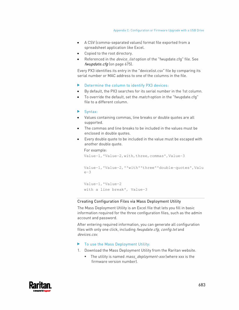
Appendix C: Configuration or Firmware Upgrade with a USB Drive
683
A CSV (comma-separated values) format file exported from a spreadsheet application like Excel.
Copied to the root directory. Referenced in the device_list option of the "fwupdate.cfg" file. See
fwupdate.cfg (on page 675).
Every PX3 identifies its entry in the "devicelist.csv" file by comparing its serial number or MAC address to one of the columns in the file.
Determine the column to identify PX3 devices: By default, the PX3 searches for its serial number in the 1st column. To override the default, set the match option in the "fwupdate.cfg"
file to a different column.
Syntax: Values containing commas, line breaks or double quotes are all
supported. The commas and line breaks to be included in the values must be
enclosed in double quotes. Every double quote to be included in the value must be escaped with
another double quote. For example: Value-1,"Value-2,with,three,commas",Value-3
Value-1,"Value-2,""with""three""double-quotes",Value-3
Value-1,"Value-2 with a line break", Value-3
Creating Configuration Files via Mass Deployment Utility
The Mass Deployment Utility is an Excel file that lets you fill in basic information required for the three configuration files, such as the admin account and password.
After entering required information, you can generate all configuration files with only one click, including fwupdate.cfg, config.txt and devices.csv.
To use the Mass Deployment Utility: 1. Download the Mass Deployment Utility from the Raritan website.
The utility is named mass_deployment-xxx (where xxx is the firmware version number).
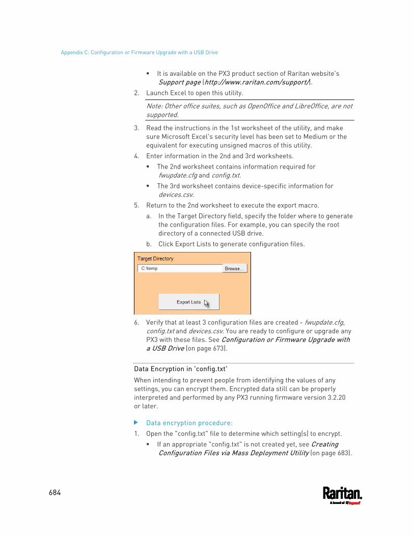
Appendix C: Configuration or Firmware Upgrade with a USB Drive
684
It is available on the PX3 product section of Raritan website's Support page (http://www.raritan.com/support/).
2. Launch Excel to open this utility.
Note: Other office suites, such as OpenOffice and LibreOffice, are not supported.
3. Read the instructions in the 1st worksheet of the utility, and make sure Microsoft Excel's security level has been set to Medium or the equivalent for executing unsigned macros of this utility.
4. Enter information in the 2nd and 3rd worksheets. The 2nd worksheet contains information required for
fwupdate.cfg and config.txt. The 3rd worksheet contains device-specific information for
devices.csv. 5. Return to the 2nd worksheet to execute the export macro.
a. In the Target Directory field, specify the folder where to generate the configuration files. For example, you can specify the root directory of a connected USB drive.
b. Click Export Lists to generate configuration files.
6. Verify that at least 3 configuration files are created - fwupdate.cfg,
config.txt and devices.csv. You are ready to configure or upgrade any PX3 with these files. See Configuration or Firmware Upgrade with a USB Drive (on page 673).
Data Encryption in 'config.txt'
When intending to prevent people from identifying the values of any settings, you can encrypt them. Encrypted data still can be properly interpreted and performed by any PX3 running firmware version 3.2.20 or later.
Data encryption procedure: 1. Open the "config.txt" file to determine which setting(s) to encrypt.
If an appropriate "config.txt" is not created yet, see Creating Configuration Files via Mass Deployment Utility (on page 683).
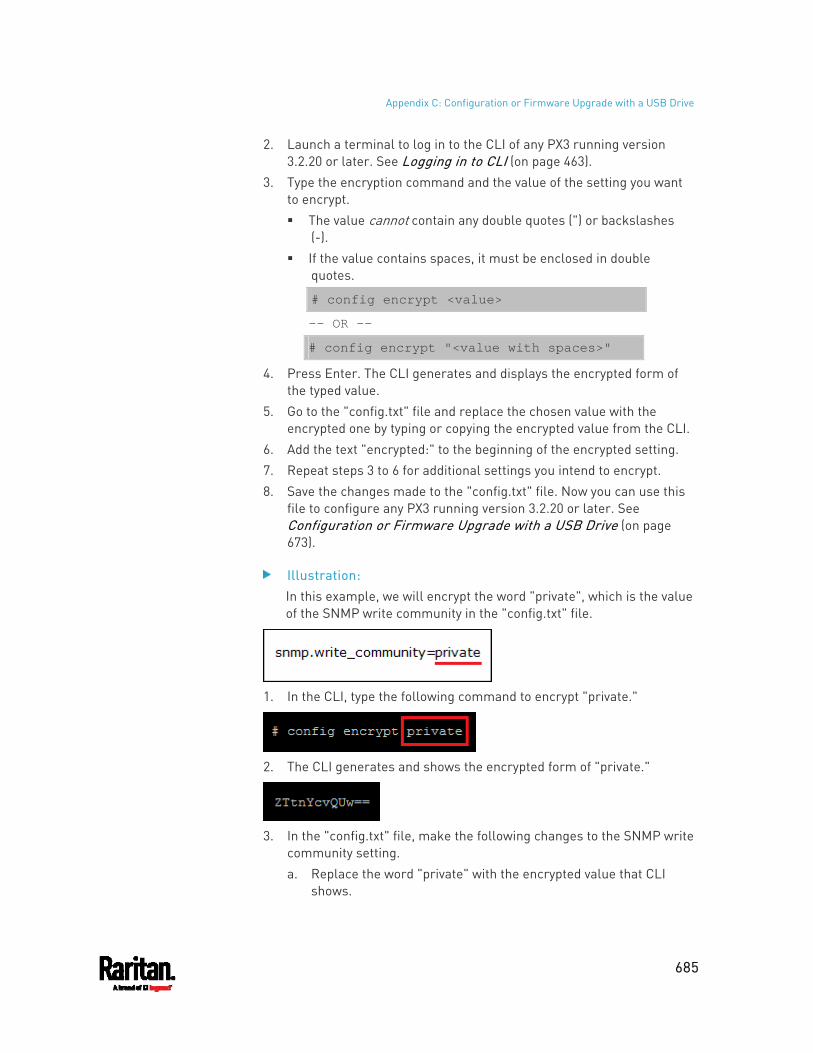
Appendix C: Configuration or Firmware Upgrade with a USB Drive
685
2. Launch a terminal to log in to the CLI of any PX3 running version 3.2.20 or later. See Logging in to CLI (on page 463).
3. Type the encryption command and the value of the setting you want to encrypt. The value cannot contain any double quotes (") or backslashes
(-). If the value contains spaces, it must be enclosed in double
quotes.
# config encrypt <value>
-- OR --
# config encrypt "<value with spaces>"
4. Press Enter. The CLI generates and displays the encrypted form of the typed value.
5. Go to the "config.txt" file and replace the chosen value with the encrypted one by typing or copying the encrypted value from the CLI.
6. Add the text "encrypted:" to the beginning of the encrypted setting. 7. Repeat steps 3 to 6 for additional settings you intend to encrypt. 8. Save the changes made to the "config.txt" file. Now you can use this
file to configure any PX3 running version 3.2.20 or later. See Configuration or Firmware Upgrade with a USB Drive (on page 673).
Illustration: In this example, we will encrypt the word "private", which is the value of the SNMP write community in the "config.txt" file.
1. In the CLI, type the following command to encrypt "private."
2. The CLI generates and shows the encrypted form of "private."
3. In the "config.txt" file, make the following changes to the SNMP write
community setting. a. Replace the word "private" with the encrypted value that CLI
shows.
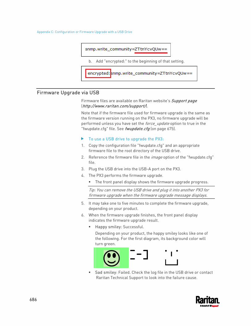
Appendix C: Configuration or Firmware Upgrade with a USB Drive
686
b. Add "encrypted:" to the beginning of that setting.
Firmware Upgrade via USB
Firmware files are available on Raritan website's Support page (http://www.raritan.com/support/).
Note that if the firmware file used for firmware upgrade is the same as the firmware version running on the PX3, no firmware upgrade will be performed unless you have set the force_update option to true in the "fwupdate.cfg" file. See fwupdate.cfg (on page 675).
To use a USB drive to upgrade the PX3: 1. Copy the configuration file "fwupdate.cfg" and an appropriate
firmware file to the root directory of the USB drive. 2. Reference the firmware file in the image option of the "fwupdate.cfg"
file. 3. Plug the USB drive into the USB-A port on the PX3. 4. The PX3 performs the firmware upgrade.
The front panel display shows the firmware upgrade progress.
Tip: You can remove the USB drive and plug it into another PX3 for firmware upgrade when the firmware upgrade message displays.
5. It may take one to five minutes to complete the firmware upgrade, depending on your product.
6. When the firmware upgrade finishes, the front panel display indicates the firmware upgrade result. Happy smiley: Successful.
Depending on your product, the happy smiley looks like one of the following. For the first diagram, its background color will turn green.
Sad smiley: Failed. Check the log file in the USB drive or contact Raritan Technical Support to look into the failure cause.

Appendix C: Configuration or Firmware Upgrade with a USB Drive
687
The sad smiley looks like one of the following. For the first diagram, its background color will turn red.
688
If a TFTP server is available, you can use it and appropriate configuration files to perform any or all of the following tasks for a large number of PX3 devices in the same network.
Initial deployment Configuration changes Firmware upgrade Downloading diagnostic data
This feature is drastically useful if you have hundreds or even thousands of PX3 devices to configure or upgrade.
Warning: The feature of bulk configuration or firmware upgrade via DHCP/TFTP only works on standalone PX3 devices directly connected to the network. This feature does NOT work for slave devices in the cascading configuration.
Tip: For the other alternatives, see Configuration or Firmware Upgrade with a USB Drive (on page 673) or Raw Configuration Upload and Download (on page 711).
In This Chapter
Bulk Configuration/Upgrade Procedure................................................. 688 TFTP Requirements ................................................................................ 689 DHCP IPv4 Configuration in Windows..................................................... 690 DHCP IPv6 Configuration in Windows..................................................... 700 DHCP IPv4 Configuration in Linux .......................................................... 707 DHCP IPv6 Configuration in Linux .......................................................... 709
Bulk Configuration/Upgrade Procedure
As of version 3.5.0, any firmware downgrade using "fwupdate.cfg" is NOT supported by default. Only firmware upgrade is permitted with "fwupdate.cfg". A special parameter is required to permit firmware downgrade via "fwupdate.cfg". See fwupdate.cfg (on page 675).
Therefore, firmware "downgrade" via DHCP/TFTP is disallowed by default since release 3.5.0.
Appendix D Bulk Configuration or Firmware Upgrade via DHCP/TFTP
Appendix D: Bulk Configuration or Firmware Upgrade via DHCP/TFTP
689
Steps of using DHCP/TFTP for bulk configuration/upgrade: 1. Create configuration files specific to your PX3 models and firmware
versions. See Configuration Files (on page 675) or contact Raritan Technical Support to properly prepare some or all of the following files: fwupdate.cfg (always required) config.txt devices.csv
Note: Supported syntax of "fwupdate.cfg" and "config.txt" may vary based on different firmware versions. If you have existing configuration files, it is suggested to double check with Raritan Technical Support for the correctness of these files prior to using this feature.
2. Configure your TFTP server properly. See TFTP Requirements (on page 689).
3. Copy ALL required configuration files into the TFTP root directory. If the tasks you will perform include firmware upgrade, an appropriate firmware binary file is also required.
4. Properly configure your DHCP server so that it refers to the file "fwupdate.cfg" on the TFTP server for your PX3. Click one or more of the following links for detailed DHCP configuration instructions, based on your operating system and the IP address type. DHCP IPv4 Configuration in Windows (on page 690) DHCP IPv6 Configuration in Windows (on page 700) DHCP IPv4 Configuration in Linux (on page 707) DHCP IPv6 Configuration in Linux (on page 709)
5. Make sure all of the desired PX3 devices use DHCP as the IP configuration method and have been directly connected to the network.
6. Re-boot these PX3 devices. The DHCP server will execute the commands in the "fwupdate.cfg" file on the TFTP server to configure or upgrade those PX3 devices supporting DHCP in the same network. DHCP will execute the "fwupdate.cfg" commands once for IPv4 and once for IPv6 respectively if both IPv4 and IPv6 settings are configured properly in DHCP.
TFTP Requirements
To perform bulk configuration or firmware upgrade successfully, your TFTP server must meet the following requirements:
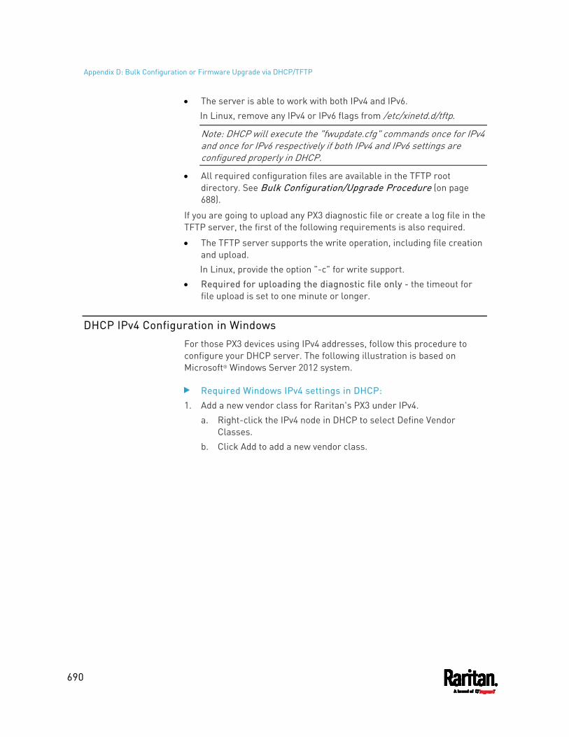
Appendix D: Bulk Configuration or Firmware Upgrade via DHCP/TFTP
690
The server is able to work with both IPv4 and IPv6. In Linux, remove any IPv4 or IPv6 flags from /etc/xinetd.d/tftp.
Note: DHCP will execute the "fwupdate.cfg" commands once for IPv4 and once for IPv6 respectively if both IPv4 and IPv6 settings are configured properly in DHCP.
All required configuration files are available in the TFTP root directory. See Bulk Configuration/Upgrade Procedure (on page 688).
If you are going to upload any PX3 diagnostic file or create a log file in the TFTP server, the first of the following requirements is also required.
The TFTP server supports the write operation, including file creation and upload. In Linux, provide the option "-c" for write support.
Required for uploading the diagnostic file only - the timeout for file upload is set to one minute or longer.
DHCP IPv4 Configuration in Windows
For those PX3 devices using IPv4 addresses, follow this procedure to configure your DHCP server. The following illustration is based on Microsoft® Windows Server 2012 system.
Required Windows IPv4 settings in DHCP: 1. Add a new vendor class for Raritan's PX3 under IPv4.
a. Right-click the IPv4 node in DHCP to select Define Vendor Classes.
b. Click Add to add a new vendor class.
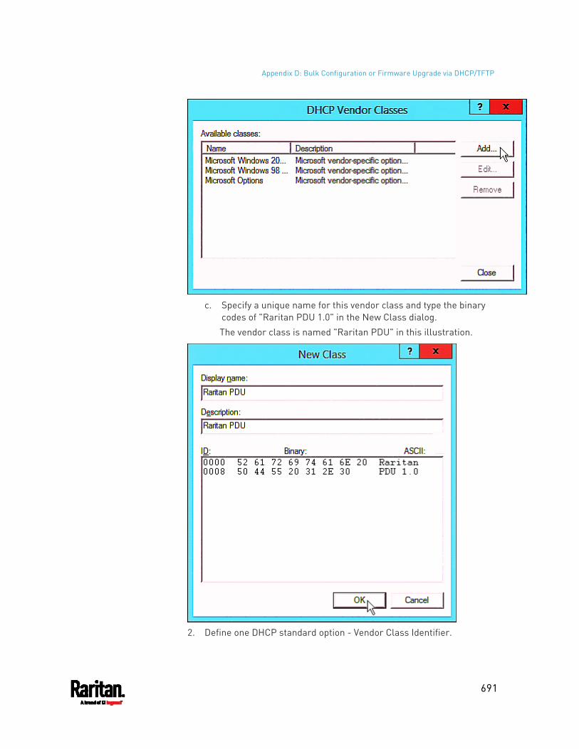
Appendix D: Bulk Configuration or Firmware Upgrade via DHCP/TFTP
691
c. Specify a unique name for this vendor class and type the binary
codes of "Raritan PDU 1.0" in the New Class dialog. The vendor class is named "Raritan PDU" in this illustration.
2. Define one DHCP standard option - Vendor Class Identifier.
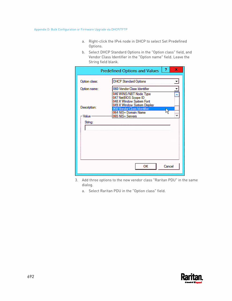
Appendix D: Bulk Configuration or Firmware Upgrade via DHCP/TFTP
692
a. Right-click the IPv4 node in DHCP to select Set Predefined Options.
b. Select DHCP Standard Options in the "Option class" field, and Vendor Class Identifier in the "Option name" field. Leave the String field blank.
3. Add three options to the new vendor class "Raritan PDU" in the same
dialog. a. Select Raritan PDU in the "Option class" field.
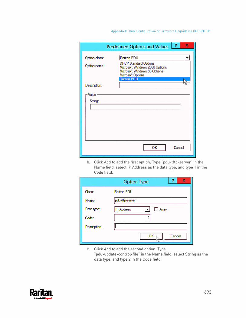
Appendix D: Bulk Configuration or Firmware Upgrade via DHCP/TFTP
693
b. Click Add to add the first option. Type "pdu-tftp-server" in the
Name field, select IP Address as the data type, and type 1 in the Code field.
c. Click Add to add the second option. Type
"pdu-update-control-file" in the Name field, select String as the data type, and type 2 in the Code field.
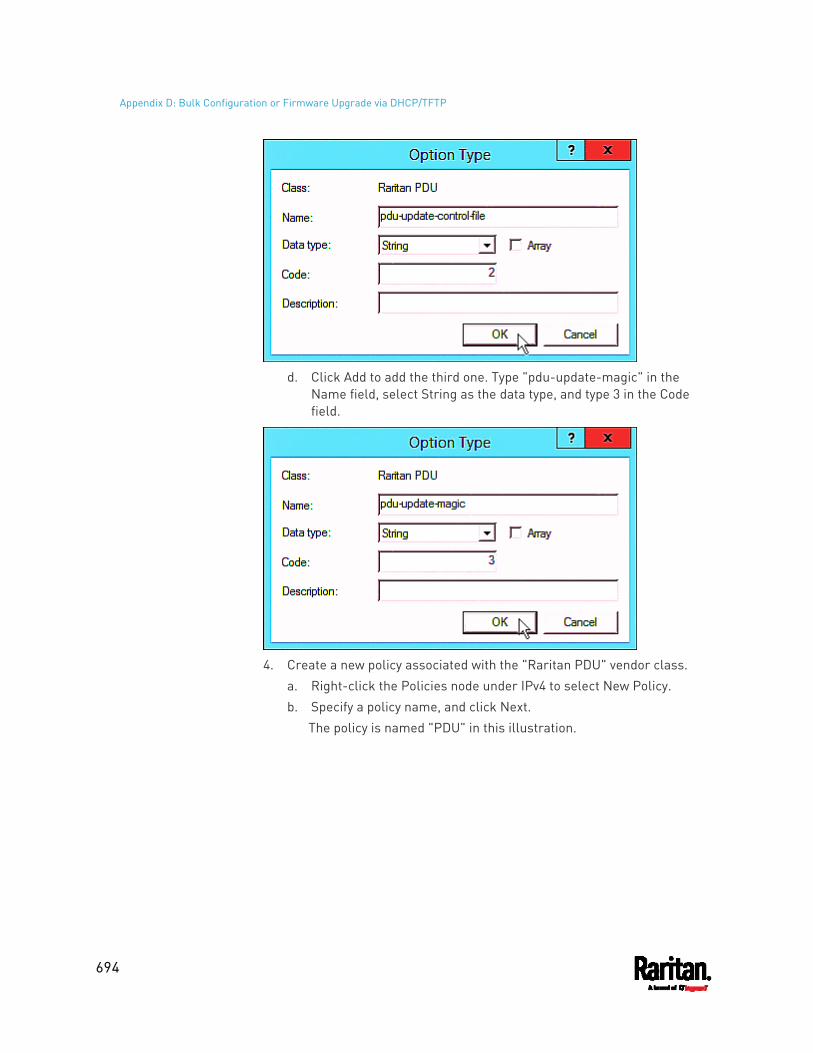
Appendix D: Bulk Configuration or Firmware Upgrade via DHCP/TFTP
694
d. Click Add to add the third one. Type "pdu-update-magic" in the
Name field, select String as the data type, and type 3 in the Code field.
4. Create a new policy associated with the "Raritan PDU" vendor class.
a. Right-click the Policies node under IPv4 to select New Policy. b. Specify a policy name, and click Next.
The policy is named "PDU" in this illustration.
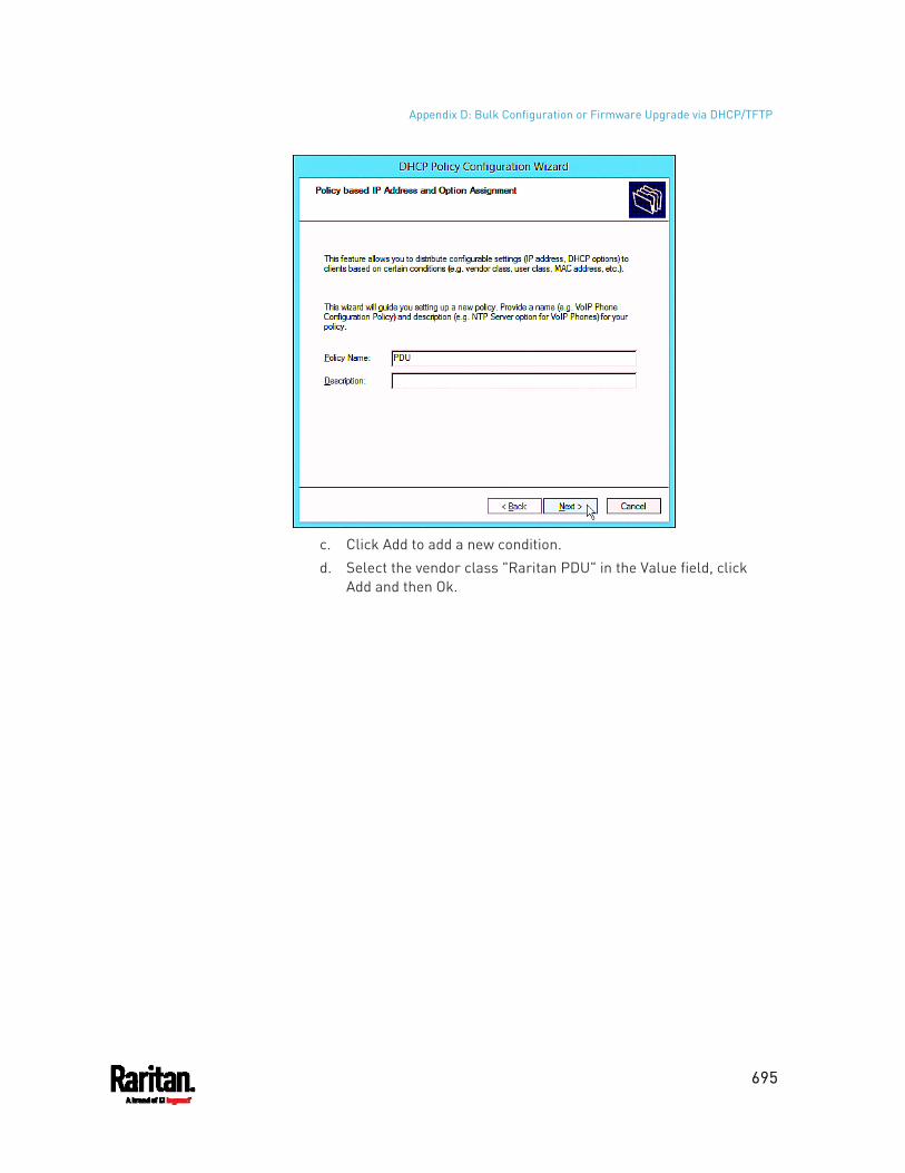
Appendix D: Bulk Configuration or Firmware Upgrade via DHCP/TFTP
695
c. Click Add to add a new condition. d. Select the vendor class "Raritan PDU" in the Value field, click
Add and then Ok.
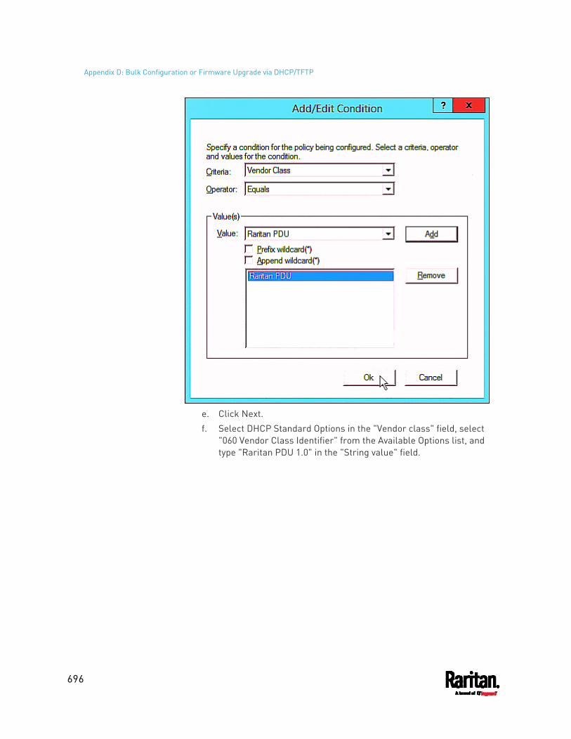
Appendix D: Bulk Configuration or Firmware Upgrade via DHCP/TFTP
696
e. Click Next. f. Select DHCP Standard Options in the "Vendor class" field, select
"060 Vendor Class Identifier" from the Available Options list, and type "Raritan PDU 1.0" in the "String value" field.
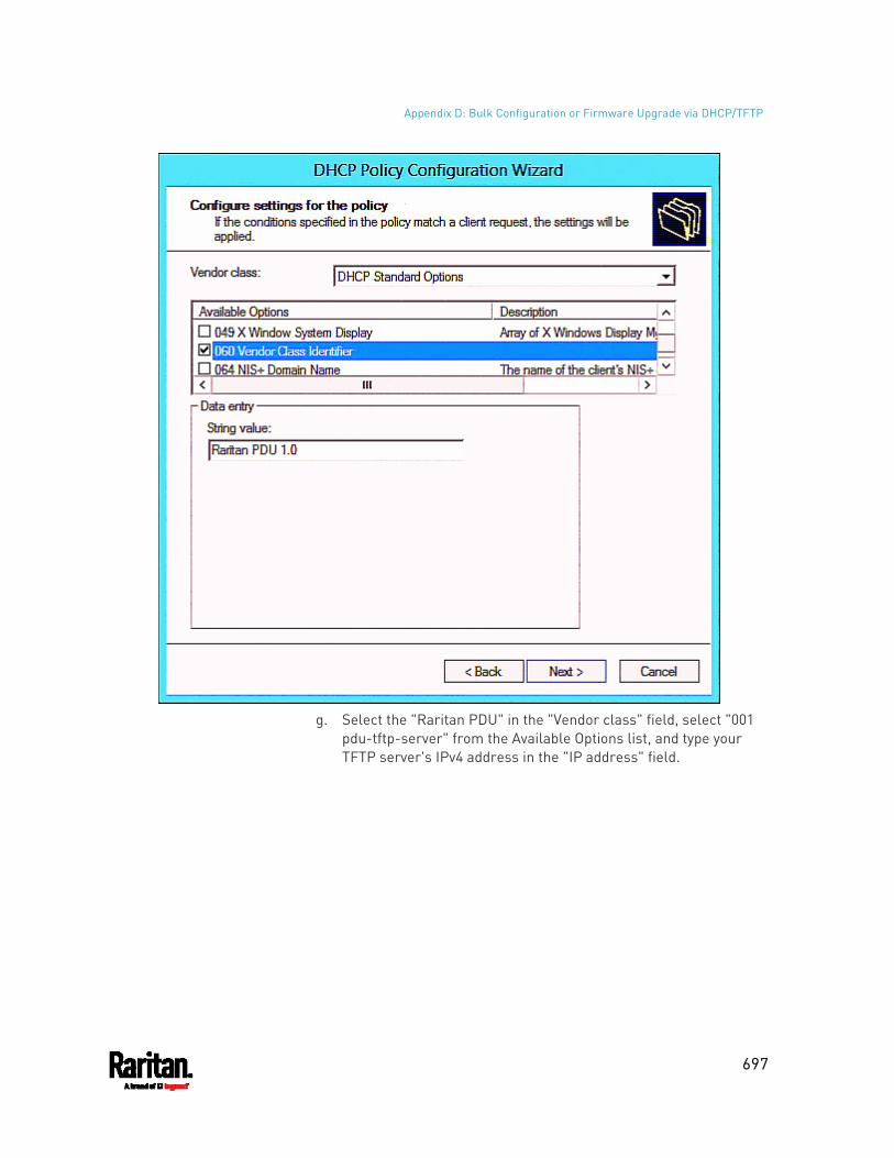
Appendix D: Bulk Configuration or Firmware Upgrade via DHCP/TFTP
697
g. Select the "Raritan PDU" in the "Vendor class" field, select "001
pdu-tftp-server" from the Available Options list, and type your TFTP server's IPv4 address in the "IP address" field.
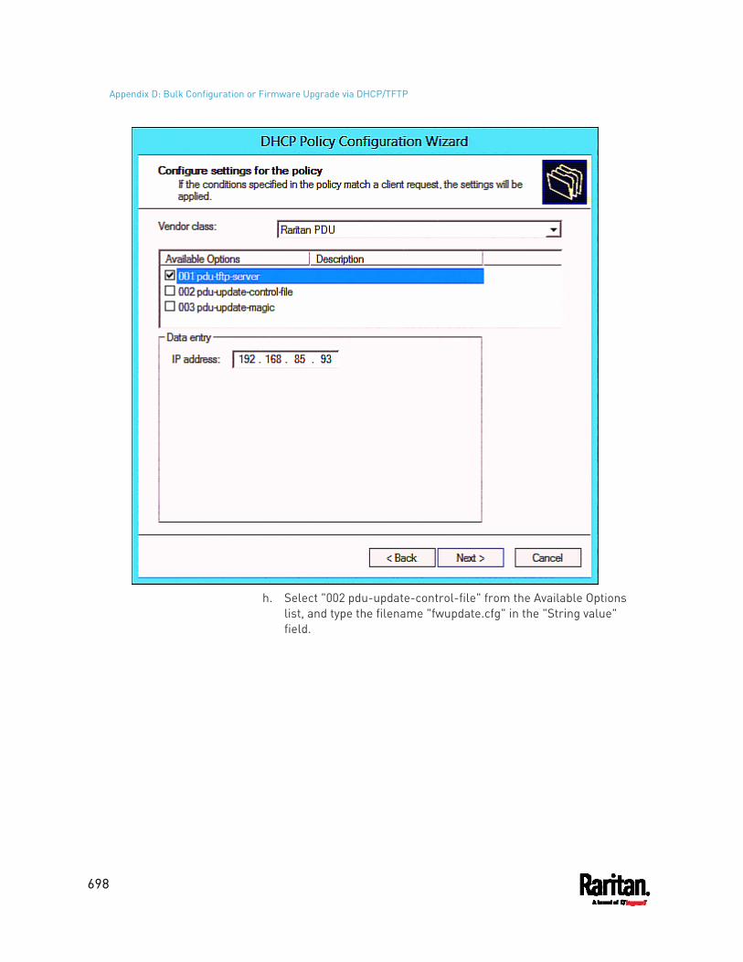
Appendix D: Bulk Configuration or Firmware Upgrade via DHCP/TFTP
698
h. Select "002 pdu-update-control-file" from the Available Options
list, and type the filename "fwupdate.cfg" in the "String value" field.
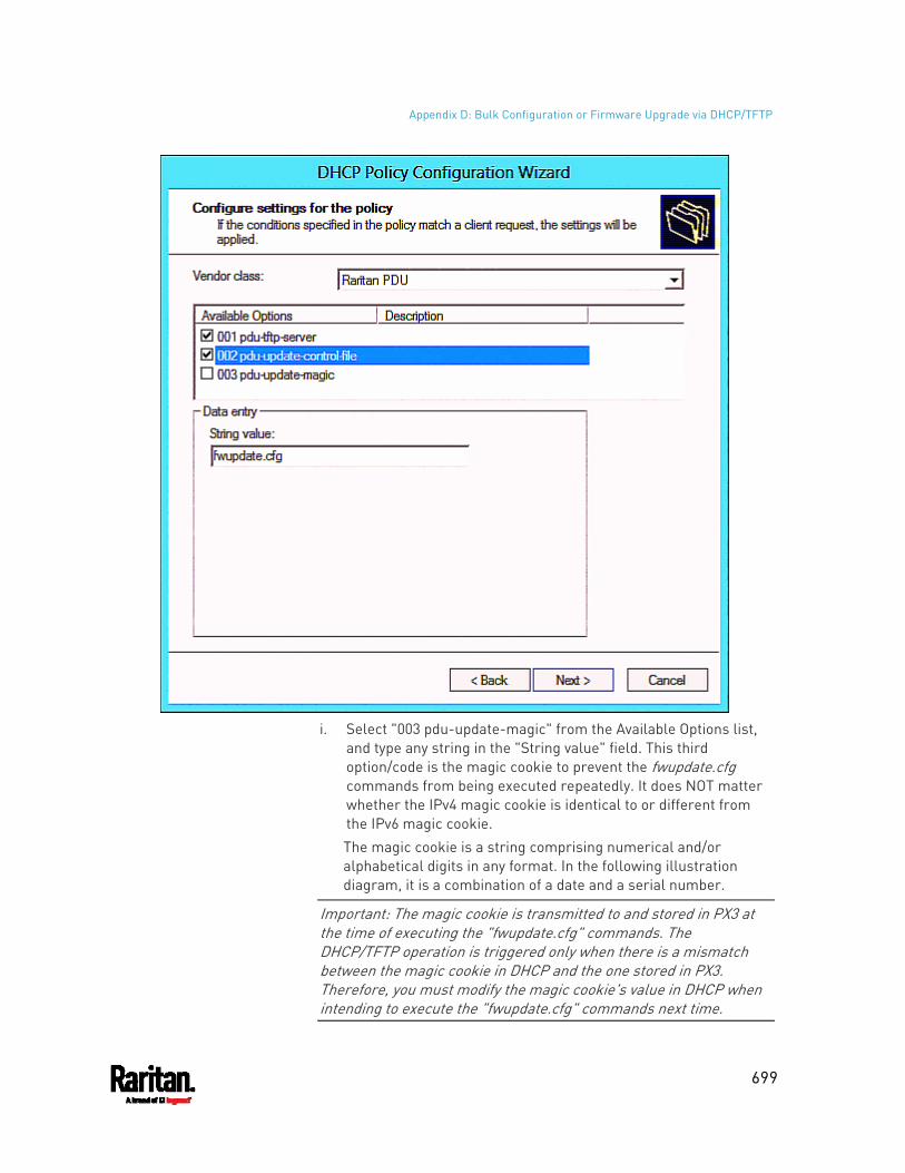
Appendix D: Bulk Configuration or Firmware Upgrade via DHCP/TFTP
699
i. Select "003 pdu-update-magic" from the Available Options list,
and type any string in the "String value" field. This third option/code is the magic cookie to prevent the fwupdate.cfg commands from being executed repeatedly. It does NOT matter whether the IPv4 magic cookie is identical to or different from the IPv6 magic cookie. The magic cookie is a string comprising numerical and/or alphabetical digits in any format. In the following illustration diagram, it is a combination of a date and a serial number.
Important: The magic cookie is transmitted to and stored in PX3 at the time of executing the "fwupdate.cfg" commands. The DHCP/TFTP operation is triggered only when there is a mismatch between the magic cookie in DHCP and the one stored in PX3. Therefore, you must modify the magic cookie's value in DHCP when intending to execute the "fwupdate.cfg" commands next time.
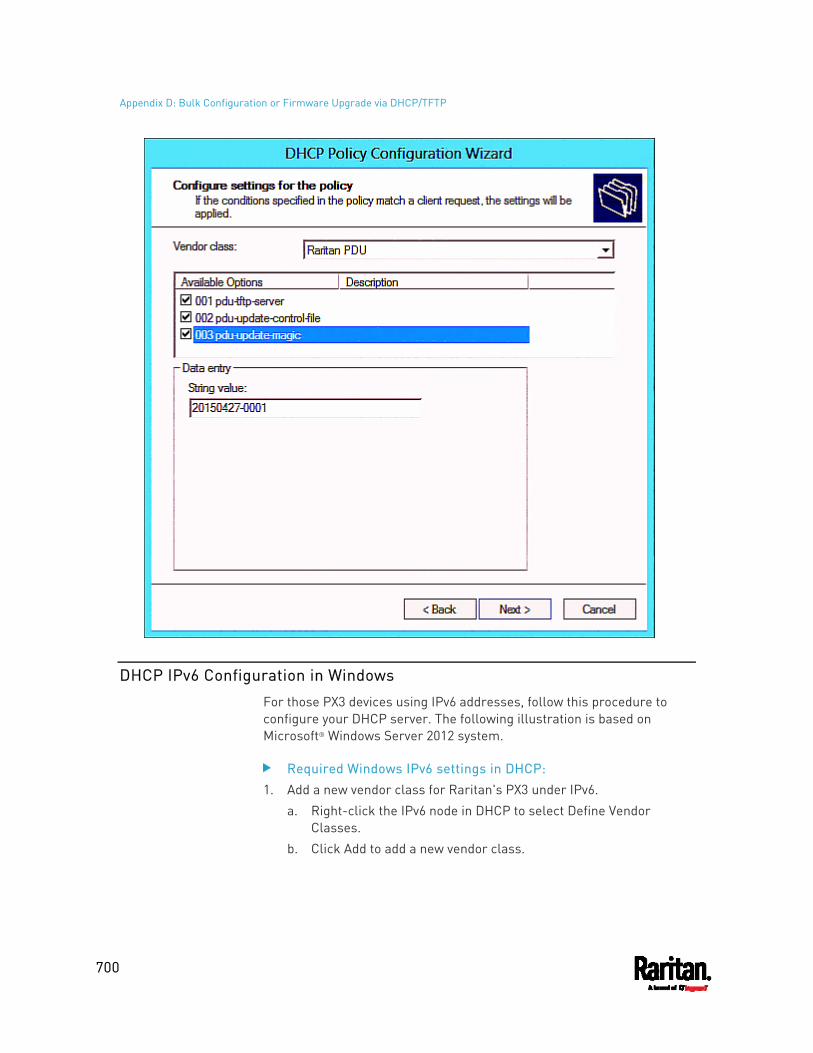
Appendix D: Bulk Configuration or Firmware Upgrade via DHCP/TFTP
700
DHCP IPv6 Configuration in Windows
For those PX3 devices using IPv6 addresses, follow this procedure to configure your DHCP server. The following illustration is based on Microsoft® Windows Server 2012 system.
Required Windows IPv6 settings in DHCP: 1. Add a new vendor class for Raritan's PX3 under IPv6.
a. Right-click the IPv6 node in DHCP to select Define Vendor Classes.
b. Click Add to add a new vendor class.
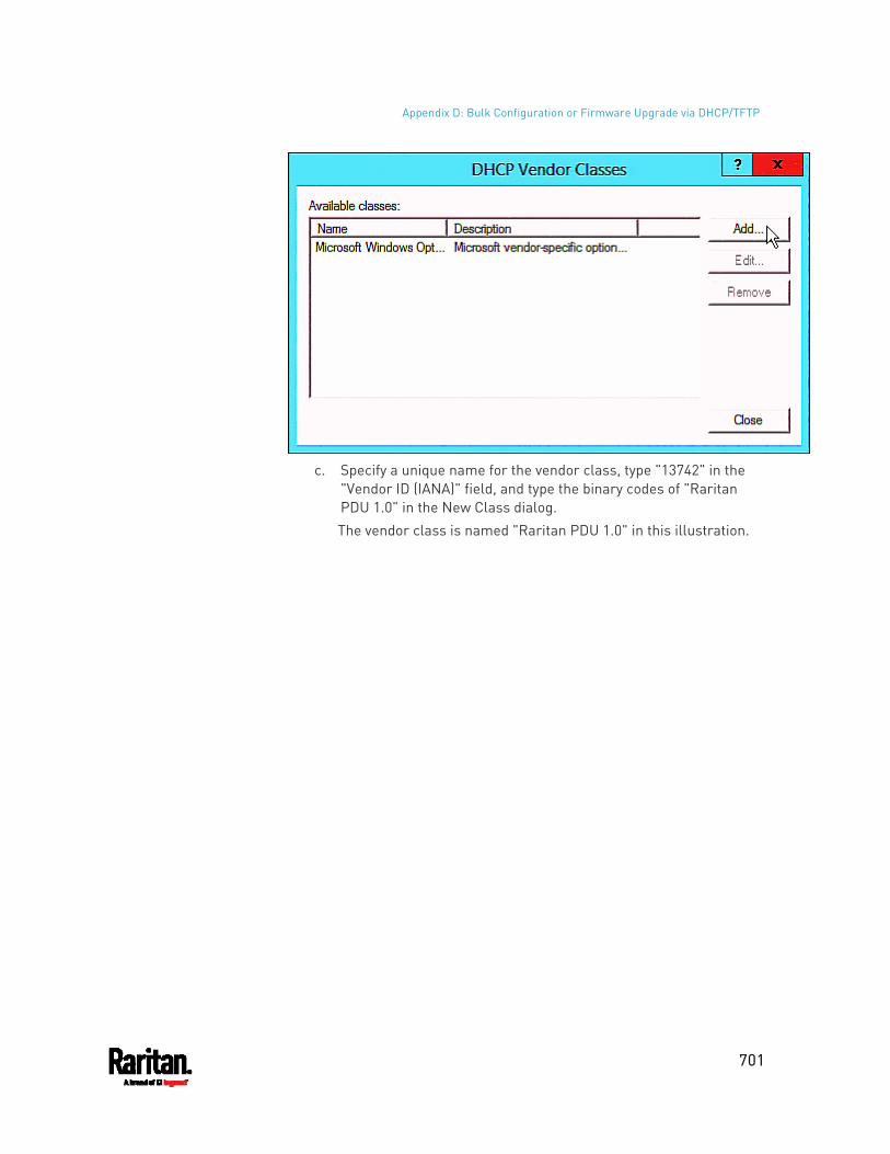
Appendix D: Bulk Configuration or Firmware Upgrade via DHCP/TFTP
701
c. Specify a unique name for the vendor class, type "13742" in the
"Vendor ID (IANA)" field, and type the binary codes of "Raritan PDU 1.0" in the New Class dialog. The vendor class is named "Raritan PDU 1.0" in this illustration.
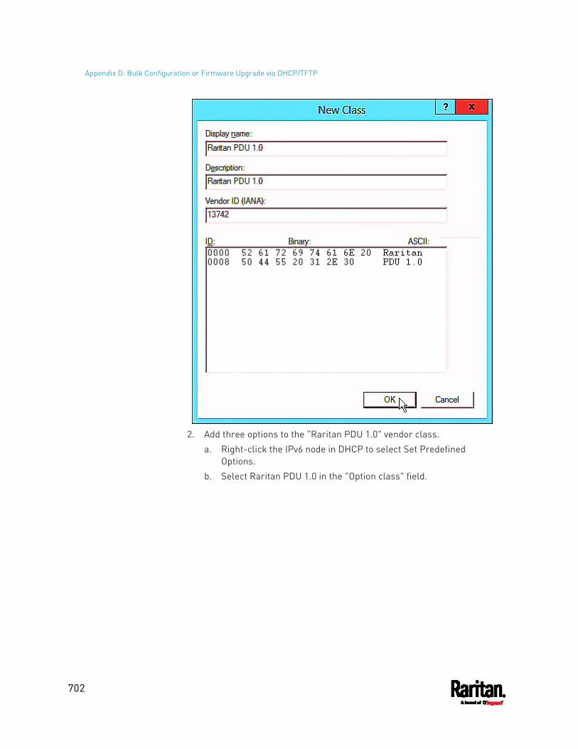
Appendix D: Bulk Configuration or Firmware Upgrade via DHCP/TFTP
702
2. Add three options to the "Raritan PDU 1.0" vendor class.
a. Right-click the IPv6 node in DHCP to select Set Predefined Options.
b. Select Raritan PDU 1.0 in the "Option class" field.
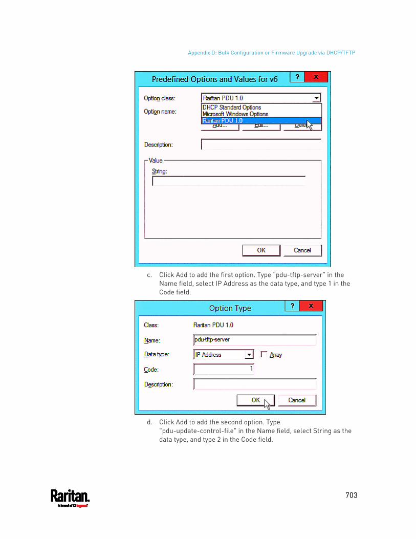
Appendix D: Bulk Configuration or Firmware Upgrade via DHCP/TFTP
703
c. Click Add to add the first option. Type "pdu-tftp-server" in the
Name field, select IP Address as the data type, and type 1 in the Code field.
d. Click Add to add the second option. Type
"pdu-update-control-file" in the Name field, select String as the data type, and type 2 in the Code field.
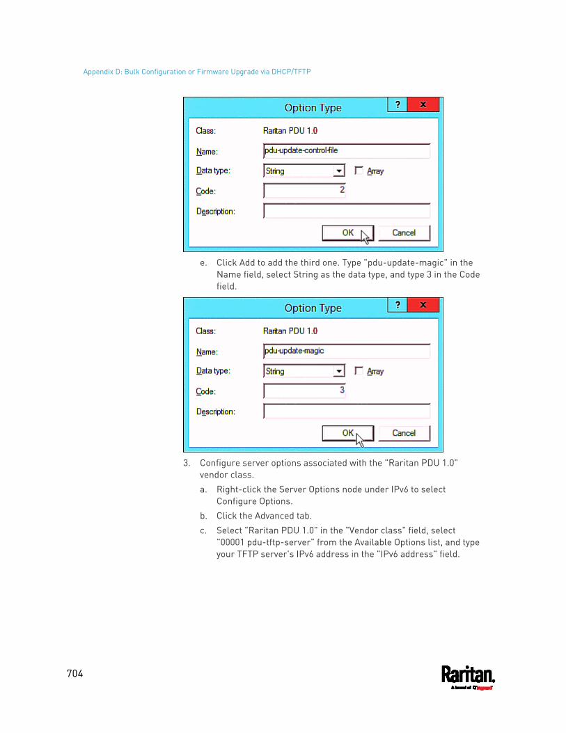
Appendix D: Bulk Configuration or Firmware Upgrade via DHCP/TFTP
704
e. Click Add to add the third one. Type "pdu-update-magic" in the
Name field, select String as the data type, and type 3 in the Code field.
3. Configure server options associated with the "Raritan PDU 1.0"
vendor class. a. Right-click the Server Options node under IPv6 to select
Configure Options. b. Click the Advanced tab. c. Select "Raritan PDU 1.0" in the "Vendor class" field, select
"00001 pdu-tftp-server" from the Available Options list, and type your TFTP server's IPv6 address in the "IPv6 address" field.
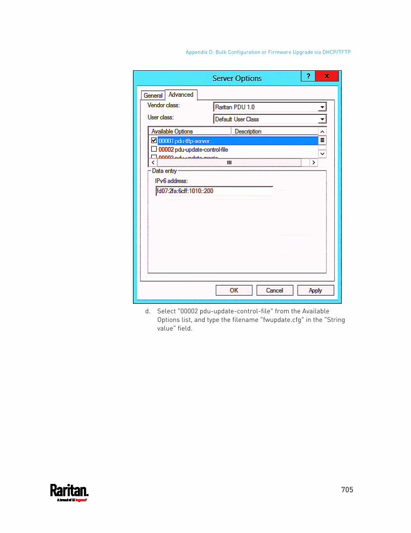
Appendix D: Bulk Configuration or Firmware Upgrade via DHCP/TFTP
705
d. Select "00002 pdu-update-control-file" from the Available
Options list, and type the filename "fwupdate.cfg" in the "String value" field.
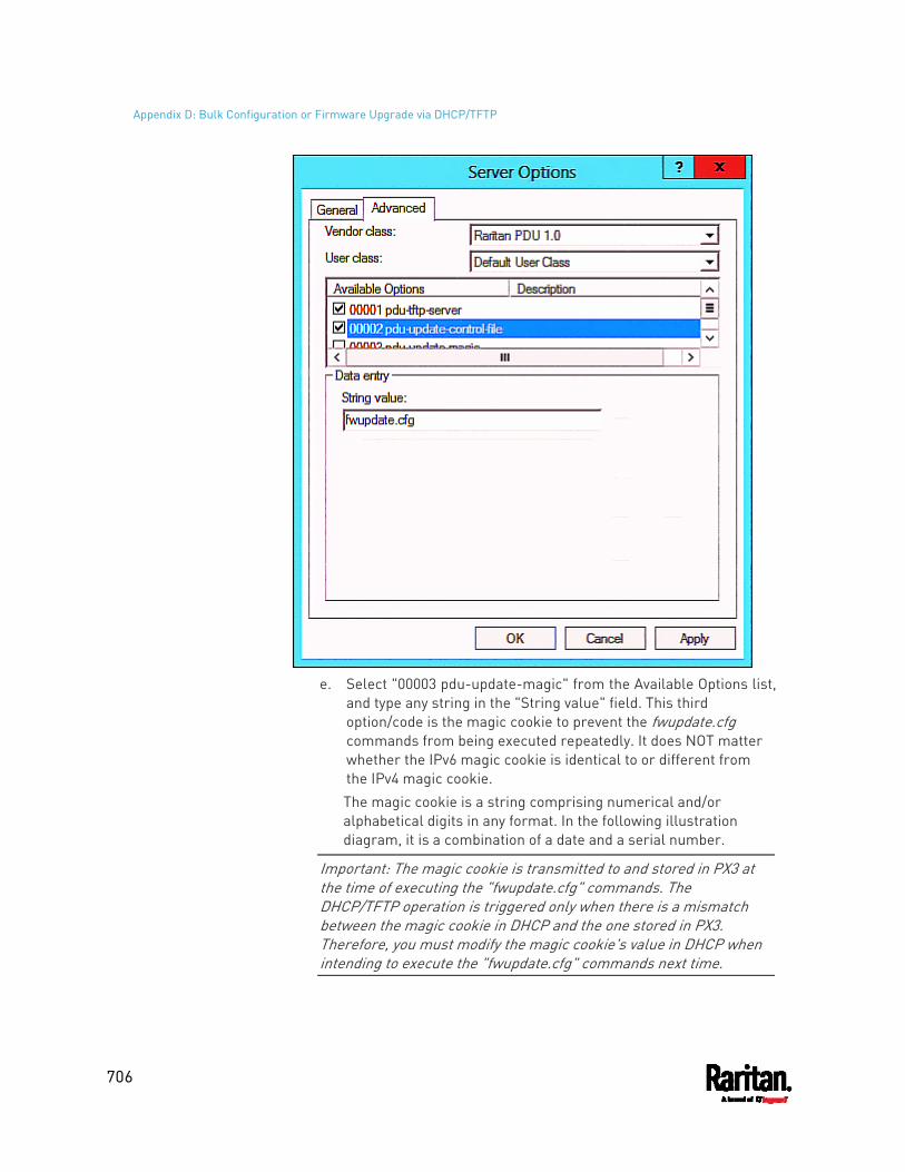
Appendix D: Bulk Configuration or Firmware Upgrade via DHCP/TFTP
706
e. Select "00003 pdu-update-magic" from the Available Options list,
and type any string in the "String value" field. This third option/code is the magic cookie to prevent the fwupdate.cfg commands from being executed repeatedly. It does NOT matter whether the IPv6 magic cookie is identical to or different from the IPv4 magic cookie. The magic cookie is a string comprising numerical and/or alphabetical digits in any format. In the following illustration diagram, it is a combination of a date and a serial number.
Important: The magic cookie is transmitted to and stored in PX3 at the time of executing the "fwupdate.cfg" commands. The DHCP/TFTP operation is triggered only when there is a mismatch between the magic cookie in DHCP and the one stored in PX3. Therefore, you must modify the magic cookie's value in DHCP when intending to execute the "fwupdate.cfg" commands next time.
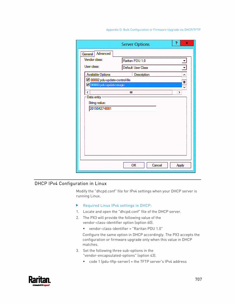
Appendix D: Bulk Configuration or Firmware Upgrade via DHCP/TFTP
707
DHCP IPv4 Configuration in Linux
Modify the "dhcpd.conf" file for IPv4 settings when your DHCP server is running Linux.
Required Linux IPv4 settings in DHCP: 1. Locate and open the "dhcpd.conf" file of the DHCP server. 2. The PX3 will provide the following value of the
vendor-class-identifier option (option 60). vendor-class-identifier = "Raritan PDU 1.0" Configure the same option in DHCP accordingly. The PX3 accepts the configuration or firmware upgrade only when this value in DHCP matches.
3. Set the following three sub-options in the "vendor-encapsulated-options" (option 43). code 1 (pdu-tftp-server) = the TFTP server's IPv4 address
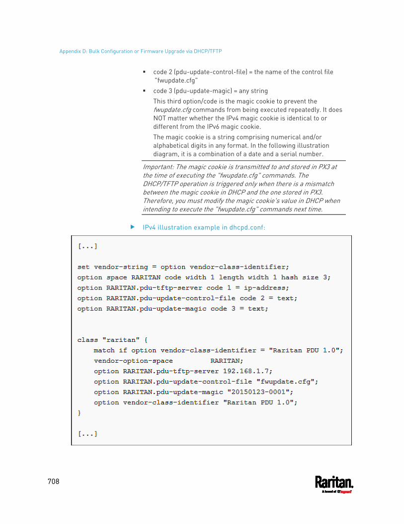
Appendix D: Bulk Configuration or Firmware Upgrade via DHCP/TFTP
708
code 2 (pdu-update-control-file) = the name of the control file "fwupdate.cfg"
code 3 (pdu-update-magic) = any string This third option/code is the magic cookie to prevent the fwupdate.cfg commands from being executed repeatedly. It does NOT matter whether the IPv4 magic cookie is identical to or different from the IPv6 magic cookie. The magic cookie is a string comprising numerical and/or alphabetical digits in any format. In the following illustration diagram, it is a combination of a date and a serial number.
Important: The magic cookie is transmitted to and stored in PX3 at the time of executing the "fwupdate.cfg" commands. The DHCP/TFTP operation is triggered only when there is a mismatch between the magic cookie in DHCP and the one stored in PX3. Therefore, you must modify the magic cookie's value in DHCP when intending to execute the "fwupdate.cfg" commands next time.
IPv4 illustration example in dhcpd.conf:
Appendix D: Bulk Configuration or Firmware Upgrade via DHCP/TFTP
709
DHCP IPv6 Configuration in Linux
Modify the "dhcpd6.conf" file for IPv6 settings when your DHCP server is running Linux.
Required Linux IPv6 settings in DHCP: 1. Locate and open the "dhcpd6.conf" file of the DHCP server. 2. The PX3 will provide the following values to the "vendor-class"
option (option 16). Configure related settings in DHCP accordingly. 13742 (Raritan's IANA number) Raritan PDU 1.0 15 (the length of the above string "Raritan PDU 1.0")
3. Set the following three sub-options in the "vendor-opts" (option 17). code 1 (pdu-tftp-server) = the TFTP server's IPv6 address code 2 (pdu-update-control-file) = the name of the control file
"fwupdate.cfg" code 3 (pdu-update-magic) = any string
This third option/code is the magic cookie to prevent the fwupdate.cfg commands from being executed repeatedly. It does NOT matter whether the IPv6 magic cookie is identical to or different from the IPv4 magic cookie. The magic cookie is a string comprising numerical and/or alphabetical digits in any format. In the following illustration diagram, it is a combination of a date and a serial number.
Important: The magic cookie is transmitted to and stored in PX3 at the time of executing the "fwupdate.cfg" commands. The DHCP/TFTP operation is triggered only when there is a mismatch between the magic cookie in DHCP and the one stored in PX3. Therefore, you must modify the magic cookie's value in DHCP when intending to execute the "fwupdate.cfg" commands next time.
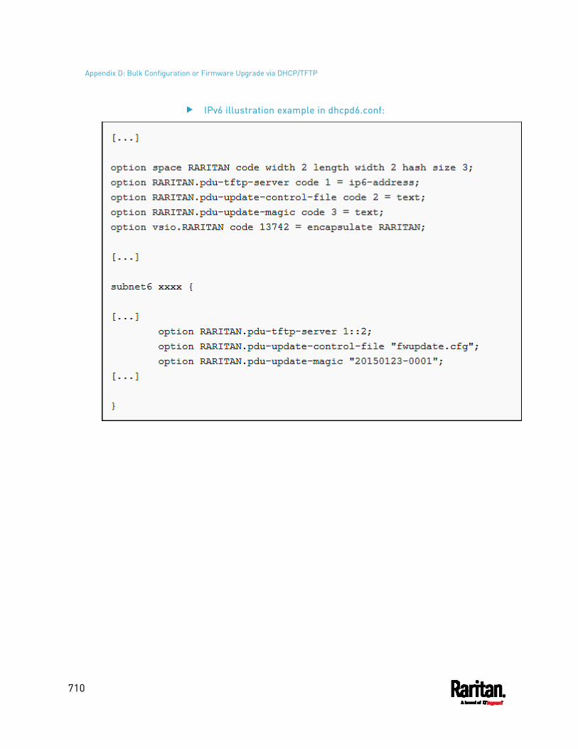
Appendix D: Bulk Configuration or Firmware Upgrade via DHCP/TFTP
710
IPv6 illustration example in dhcpd6.conf:
711
You can modify any existing "config.txt", and then upload it to a specific PX3 for modifying part or all of its settings.
There are two ways to get one "config.txt":
You create this file by yourself, either using or not using the Mass Deployment Utility. See Configuration Files (on page 675) and config.txt (on page 680).
You download the raw configuration data from any PX3.
The downloaded raw configuration contains "almost" all of current settings on your PX3.
Warning: Some configuration keys in the downloaded raw configuration are commented out, and those must NOT be part of the configuration that will be uploaded to any PX3. See Keys that Cannot Be Uploaded (on page 649).
Both configuration download and upload operations require the Administrator Privileges.
In This Chapter
Downloading Raw Configuration............................................................. 711 Uploading Raw Configuration ................................................................. 713
Downloading Raw Configuration
There are three download methods:
Web browsers: See Download via Web Browsers (on page 711). SCP or PSCP command: See Uploading or Downloading Raw
Configuration Data (on page 645). CURL command: See Download via Curl (on page 712).
Download via Web Browsers
There are two scenarios by using web browsers.
URL containing login credentials:
To log in immediately while issuing the download request, type an URL containing the login credentials in the web browser.
Appendix E Raw Configuration Upload and Download
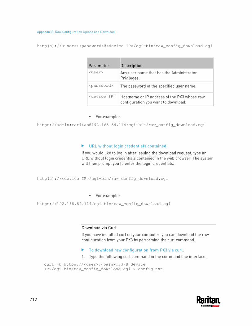
Appendix E: Raw Configuration Upload and Download
712
http(s)://<user>:<password>@<device IP>/cgi-bin/raw_config_download.cgi
Parameter Description <user> Any user name that has the Administrator
Privileges.
<password> The password of the specified user name.
<device IP> Hostname or IP address of the PX3 whose raw configuration you want to download.
For example:
https://admin:[email protected]/cgi-bin/raw_config_download.cgi
URL without login credentials contained:
If you would like to log in after issuing the download request, type an URL without login credentials contained in the web browser. The system will then prompt you to enter the login credentials.
http(s)://<device IP>/cgi-bin/raw_config_download.cgi
For example:
https://192.168.84.114/cgi-bin/raw_config_download.cgi
Download via Curl
If you have installed curl on your computer, you can download the raw configuration from your PX3 by performing the curl command.
To download raw configuration from PX3 via curl: 1. Type the following curl command in the command line interface.
curl -k https://<user>:<password>@<device IP>/cgi-bin/raw_config_download.cgi > config.txt
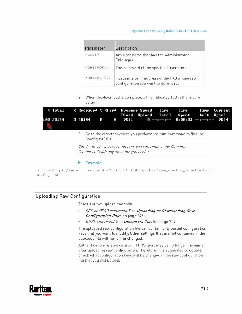
Appendix E: Raw Configuration Upload and Download
713
Parameter Description <user> Any user name that has the Administrator
Privileges.
<password> The password of the specified user name.
<device IP> Hostname or IP address of the PX3 whose raw configuration you want to download.
2. When the download is complete, a line indicates 100 in the first %
column.
3. Go to the directory where you perform the curl command to find the
"config.txt" file.
Tip: In the above curl command, you can replace the filename "config.txt" with any filename you prefer.
Example:
curl -k https://admin:[email protected]/cgi-bin/raw_config_download.cgi > config.txt
Uploading Raw Configuration
There are two upload methods:
SCP or PSCP command: See Uploading or Downloading Raw Configuration Data (on page 645).
CURL command: See Upload via Curl (on page 714).
The uploaded raw configuration file can contain only partial configuration keys that you want to modify. Other settings that are not contained in the uploaded file will remain unchanged.
Authentication-related data or HTTP(S) port may be no longer the same after uploading raw configuration. Therefore, it is suggested to double check what configuration keys will be changed in the raw configuration file that you will upload.
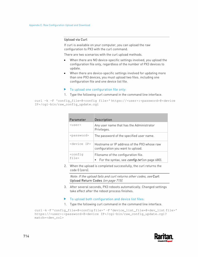
Appendix E: Raw Configuration Upload and Download
714
Upload via Curl
If curl is available on your computer, you can upload the raw configuration to PX3 with the curl command.
There are two scenarios with the curl upload methods.
When there are NO device-specific settings involved, you upload the configuration file only, regardless of the number of PX3 devices to update.
When there are device-specific settings involved for updating more than one PX3 devices, you must upload two files. including one configuration file and one device list file.
To upload one configuration file only: 1. Type the following curl command in the command line interface.
curl -k -F "config_file=@<config file>" https://<user>:<password>@<device IP>/cgi-bin/raw_config_update.cgi
Parameter Description <user> Any user name that has the Administrator
Privileges.
<password> The password of the specified user name.
<device IP> Hostname or IP address of the PX3 whose raw configuration you want to upload.
<config file>
Filename of the configuration file. For the syntax, see config.txt (on page 680).
2. When the upload is completed successfully, the curl returns the code 0 (zero).
Note: If the upload fails and curl returns other codes, see Curl Upload Return Codes (on page 715).
3. After several seconds, PX3 reboots automatically. Changed settings take effect after the reboot process finishes.
To upload both configuration and device list files: 1. Type the following curl command in the command line interface.
curl -k -F "config_file=@<config file>" -F "device_list_file=@<dev_list file>" https://<user>:<password>@<device IP>/cgi-bin/raw_config_update.cgi? match=<dev_col>
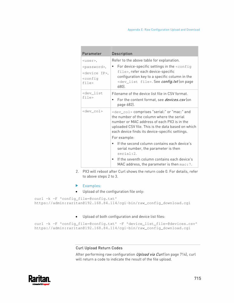
Appendix E: Raw Configuration Upload and Download
715
Parameter Description
<user>,
<password>,
<device IP>,<config file>
Refer to the above table for explanation.
For device-specific settings in the <config file>, refer each device-specific configuration key to a specific column in the <dev_list file>. See config.txt (on page 680).
<dev_list file>
Filename of the device list file in CSV format. For the content format, see devices.csv (on
page 682).
<dev_col> <dev_col> comprises "serial:" or "mac:" and the number of the column where the serial number or MAC address of each PX3 is in the uploaded CSV file. This is the data based on which each device finds its device-specific settings. For example: If the second column contains each device's
serial number, the parameter is then serial:2.
If the seventh column contains each device's MAC address, the parameter is then mac:7.
2. PX3 will reboot after Curl shows the return code 0. For details, refer to above steps 2 to 3.
Examples: Upload of the configuration file only:
curl -k -F "[email protected]" https://admin:[email protected]/cgi-bin/raw_config_download.cgi
Upload of both configuration and device list files:
curl -k -F "[email protected]" -F "[email protected]" https://admin:[email protected]/cgi-bin/raw_config_download.cgi
Curl Upload Return Codes
After performing raw configuration Upload via Curl (on page 714), curl will return a code to indicate the result of the file upload.
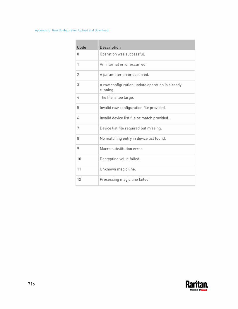
Appendix E: Raw Configuration Upload and Download
716
Code Description
0 Operation was successful.
1 An internal error occurred.
2 A parameter error occurred.
3 A raw configuration update operation is already running.
4 The file is too large.
5 Invalid raw configuration file provided.
6 Invalid device list file or match provided.
7 Device list file required but missing.
8 No matching entry in device list found.
9 Macro substitution error.
10 Decrypting value failed.
11 Unknown magic line.
12 Processing magic line failed.
717
You can use either the reset button or the command line interface (CLI) to reset the PX3.
Important: Exercise caution before resetting the PX3 to its factory defaults. This erases existing information and customized settings, such as user profiles, threshold values, and so on. Only active energy data and firmware upgrade history are retained.
Alternative:
Another method to reset it to factory defaults is to use the web interface. See Resetting All Settings to Factory Defaults (on page 430).
In This Chapter
Using the Reset Button ........................................................................... 717 Using the CLI Command ......................................................................... 718
Using the Reset Button
An RS-232 serial connection to a computer is required for using the reset button.
To reset to factory defaults using the reset button: 1. Connect a computer to the PX3. See Connecting the PX3 to a
Computer (on page 28). 2. Launch a terminal emulation program such as Kermit or PuTTY, and
open a window on the PX3. For information on the serial port configuration, see Step 2 of Initial Network Configuration via CLI (on page 828).
3. Press (and release) the Reset button of the PX3 device while pressing the Esc key of the keyboard several times in rapid succession. A prompt (=>) should appear after about one second.
4. Type defaults to reset the PX3 to its factory defaults. 5. Wait until the Username prompt appears, indicating the reset is
complete. The following illustrates the reset button on Zero U PDUs. Port locations may differ on your models. PX3 Zero U:
Appendix F Resetting to Factory Defaults
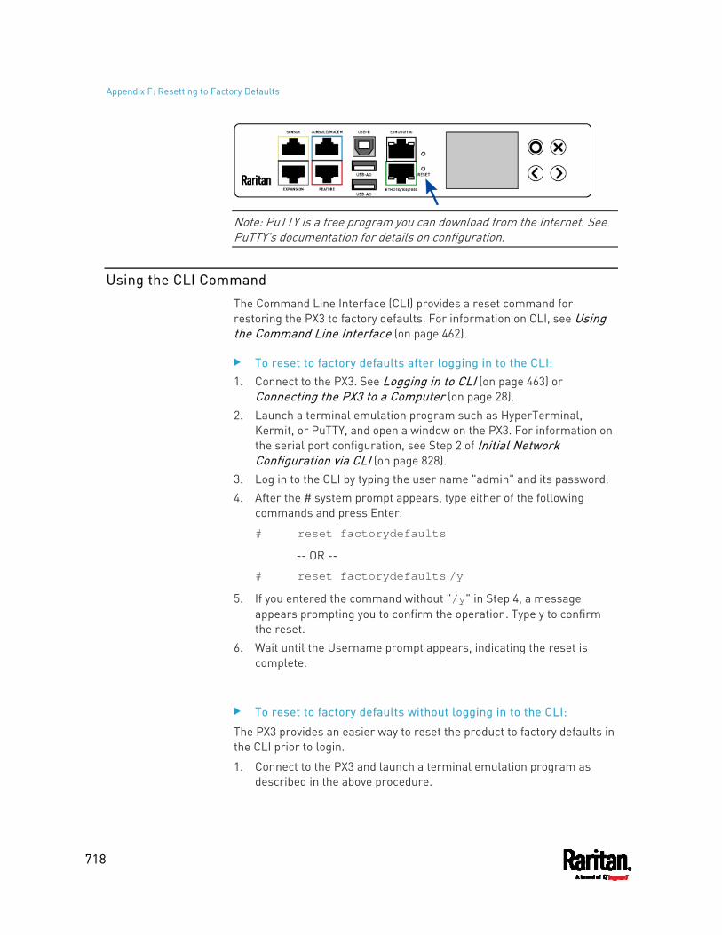
Appendix F: Resetting to Factory Defaults
718
Note: PuTTY is a free program you can download from the Internet. See PuTTY's documentation for details on configuration.
Using the CLI Command
The Command Line Interface (CLI) provides a reset command for restoring the PX3 to factory defaults. For information on CLI, see Using the Command Line Interface (on page 462).
To reset to factory defaults after logging in to the CLI: 1. Connect to the PX3. See Logging in to CLI (on page 463) or
Connecting the PX3 to a Computer (on page 28). 2. Launch a terminal emulation program such as HyperTerminal,
Kermit, or PuTTY, and open a window on the PX3. For information on the serial port configuration, see Step 2 of Initial Network Configuration via CLI (on page 828).
3. Log in to the CLI by typing the user name "admin" and its password. 4. After the # system prompt appears, type either of the following
commands and press Enter.
# reset factorydefaults
-- OR --
# reset factorydefaults /y
5. If you entered the command without "/y" in Step 4, a message appears prompting you to confirm the operation. Type y to confirm the reset.
6. Wait until the Username prompt appears, indicating the reset is complete.
To reset to factory defaults without logging in to the CLI:
The PX3 provides an easier way to reset the product to factory defaults in the CLI prior to login.
1. Connect to the PX3 and launch a terminal emulation program as described in the above procedure.

Appendix F: Resetting to Factory Defaults
719
2. At the Username prompt in the CLI, type "factorydefaults" and press Enter.
Username: factorydefaults
3. Type y on a confirmation message to perform the reset.
720
PX3 models with residual current monitoring (RCM) detect and report residual current - abnormal flow of current into the protective earth conductor.
Residual current is a safety issue since electrocution is possible if the rack or any device within it is touched.
Depending on the model you purchase, some models report residual current by inlet only, while some models report residual current by inlet pole. In addition, some models are able to report residual DC current in addition to the total residual current.
Warning: PX3 RCM cannot disconnect power to stop residual current flow. Devices like RCD and GFI disconnect power when residual current is detected, but the PX3 with RCM are NOT RCD or GFI protected devices.
In This Chapter
RCM Current Sensor ............................................................................... 720 RCM State Sensor ................................................................................... 721 Compliance with IEC 62020..................................................................... 722 RCM Self-Test ......................................................................................... 723 Web Interface Operations for RCM ......................................................... 723 Front Panel Operations for RCM............................................................. 730 RCM SNMP Operations ........................................................................... 734 CLI Operations for RCM .......................................................................... 735
RCM Current Sensor
The RCM current sensor detects current imbalance which indicates current is flowing to ground. The sensor cannot determine the exact location. It just reports the sum of all residual current in the PDU and devices plugged into it, which is either per inlet or per inlet pole, depending on the model.
Most equipment leaks a small amount of current and the UL/IEC 60950-1 standard for IT equipment permits up to 3mA. For example, if a PDU has one RCM sensor on its inlet and twenty plugged-in devices -- each leaking 1mA, the RCM sensor then reports the sum - 20mA.
Raritan offers two types of RCM sensors.
Appendix G PX3 Models with Residual Current Monitoring
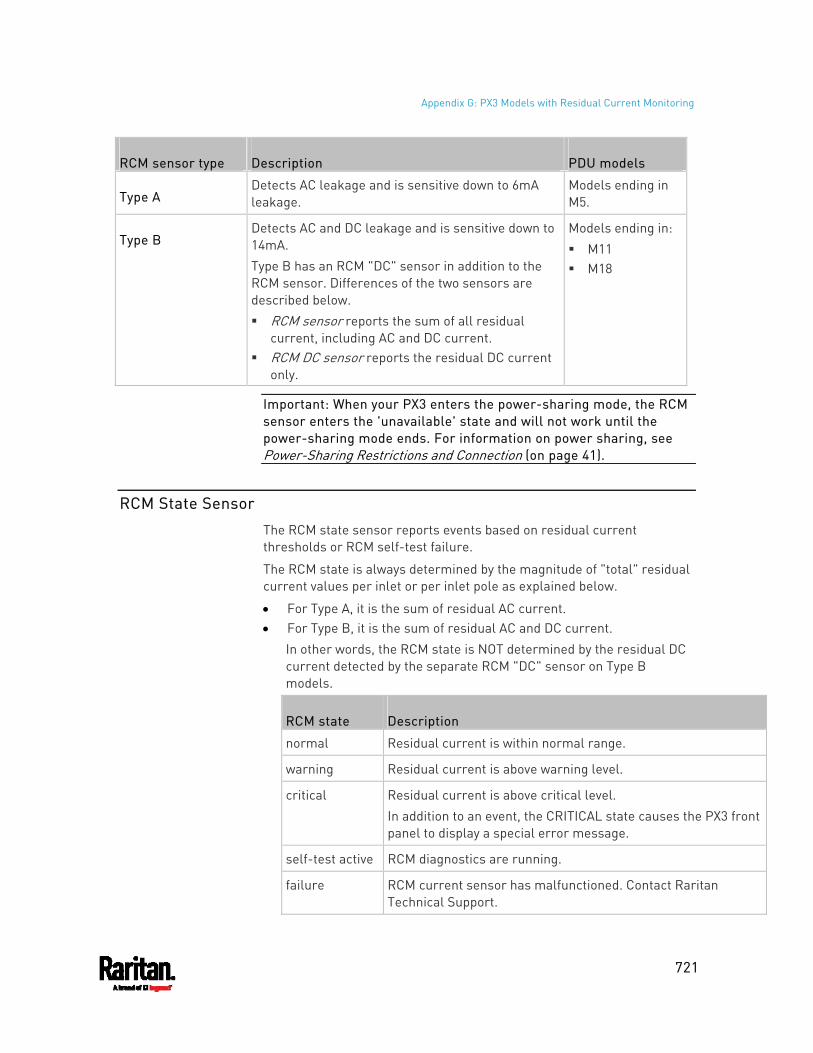
Appendix G: PX3 Models with Residual Current Monitoring
721
RCM sensor type Description PDU models
Type A Detects AC leakage and is sensitive down to 6mA leakage.
Models ending in M5.
Type B Detects AC and DC leakage and is sensitive down to 14mA. Type B has an RCM "DC" sensor in addition to the RCM sensor. Differences of the two sensors are described below. RCM sensor reports the sum of all residual
current, including AC and DC current. RCM DC sensor reports the residual DC current
only.
Models ending in: M11 M18
Important: When your PX3 enters the power-sharing mode, the RCM sensor enters the 'unavailable' state and will not work until the power-sharing mode ends. For information on power sharing, see Power-Sharing Restrictions and Connection (on page 41).
RCM State Sensor
The RCM state sensor reports events based on residual current thresholds or RCM self-test failure.
The RCM state is always determined by the magnitude of "total" residual current values per inlet or per inlet pole as explained below.
For Type A, it is the sum of residual AC current. For Type B, it is the sum of residual AC and DC current.
In other words, the RCM state is NOT determined by the residual DC current detected by the separate RCM "DC" sensor on Type B models.
RCM state Description
normal Residual current is within normal range.
warning Residual current is above warning level.
critical Residual current is above critical level. In addition to an event, the CRITICAL state causes the PX3 front panel to display a special error message.
self-test active RCM diagnostics are running.
failure RCM current sensor has malfunctioned. Contact Raritan Technical Support.
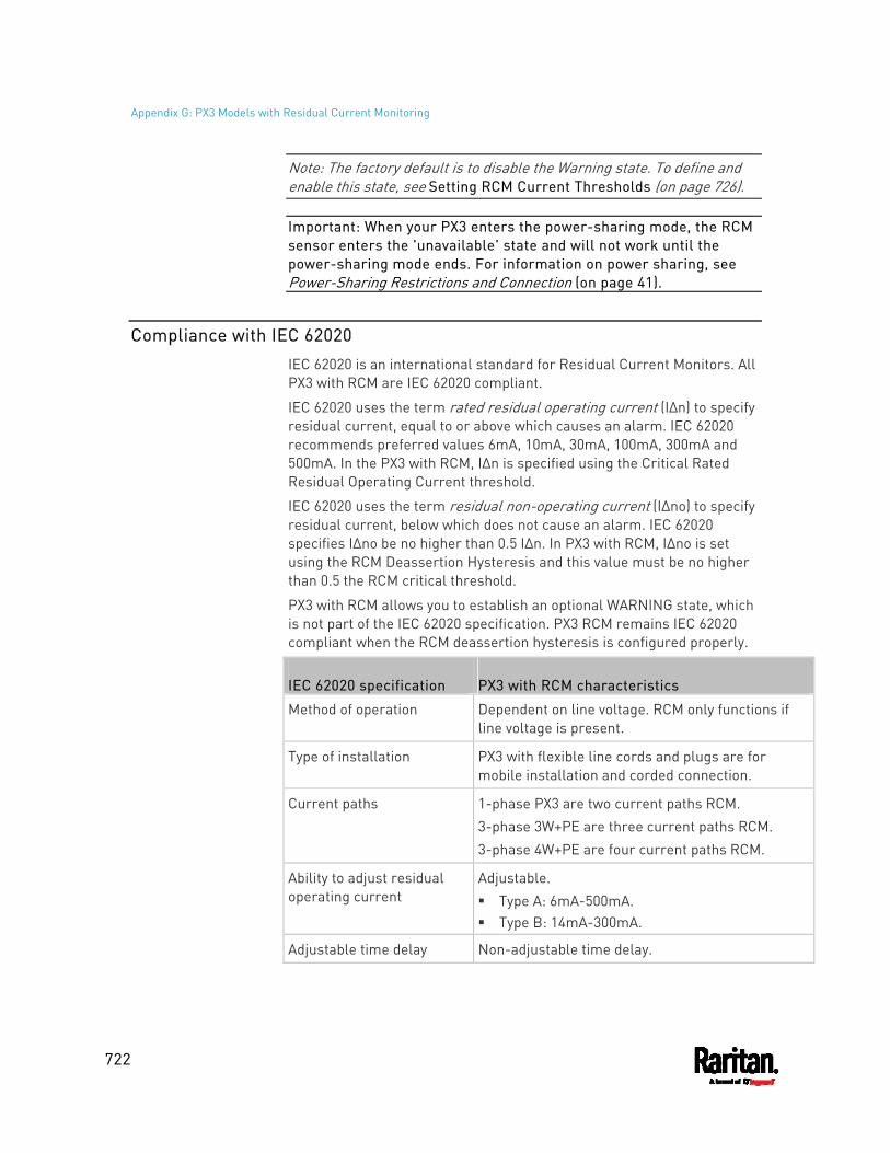
Appendix G: PX3 Models with Residual Current Monitoring
722
Note: The factory default is to disable the Warning state. To define and enable this state, see Setting RCM Current Thresholds (on page 726).
Important: When your PX3 enters the power-sharing mode, the RCM sensor enters the 'unavailable' state and will not work until the power-sharing mode ends. For information on power sharing, see Power-Sharing Restrictions and Connection (on page 41).
Compliance with IEC 62020
IEC 62020 is an international standard for Residual Current Monitors. All PX3 with RCM are IEC 62020 compliant.
IEC 62020 uses the term rated residual operating current (IΔn) to specify residual current, equal to or above which causes an alarm. IEC 62020 recommends preferred values 6mA, 10mA, 30mA, 100mA, 300mA and 500mA. In the PX3 with RCM, IΔn is specified using the Critical Rated Residual Operating Current threshold.
IEC 62020 uses the term residual non-operating current (IΔno) to specify residual current, below which does not cause an alarm. IEC 62020 specifies IΔno be no higher than 0.5 IΔn. In PX3 with RCM, IΔno is set using the RCM Deassertion Hysteresis and this value must be no higher than 0.5 the RCM critical threshold.
PX3 with RCM allows you to establish an optional WARNING state, which is not part of the IEC 62020 specification. PX3 RCM remains IEC 62020 compliant when the RCM deassertion hysteresis is configured properly.
IEC 62020 specification PX3 with RCM characteristics
Method of operation Dependent on line voltage. RCM only functions if line voltage is present.
Type of installation PX3 with flexible line cords and plugs are for mobile installation and corded connection.
Current paths 1-phase PX3 are two current paths RCM. 3-phase 3W+PE are three current paths RCM. 3-phase 4W+PE are four current paths RCM.
Ability to adjust residual operating current
Adjustable. Type A: 6mA-500mA. Type B: 14mA-300mA.
Adjustable time delay Non-adjustable time delay.
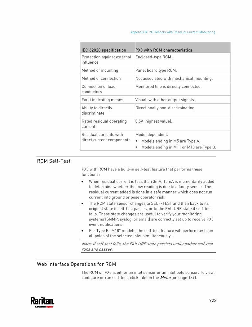
Appendix G: PX3 Models with Residual Current Monitoring
723
IEC 62020 specification PX3 with RCM characteristics
Protection against external influence
Enclosed-type RCM.
Method of mounting Panel board type RCM.
Method of connection Not associated with mechanical mounting.
Connection of load conductors
Monitored line is directly connected.
Fault indicating means Visual, with other output signals.
Ability to directly discriminate
Directionally non-discriminating.
Rated residual operating current
0.5A (highest value).
Residual currents with direct current components
Model dependent. Models ending in M5 are Type A. Models ending in M11 or M18 are Type B.
RCM Self-Test
PX3 with RCM have a built-in self-test feature that performs these functions:
When residual current is less than 3mA, 15mA is momentarily added to determine whether the low reading is due to a faulty sensor. The residual current added is done in a safe manner which does not run current into ground or pose operator risk.
The RCM state sensor changes to SELF-TEST and then back to its original state if self-test passes, or to the FAILURE state if self-test fails. These state changes are useful to verify your monitoring systems (SNMP, syslog, or email) are correctly set up to receive PX3 event notifications.
For Type B "M18" models, the self-test feature will perform tests on all poles of the selected inlet simultaneously.
Note: If self-test fails, the FAILURE state persists until another self-test runs and passes.
Web Interface Operations for RCM
The RCM on PX3 is either an inlet sensor or an inlet pole sensor. To view, configure or run self-test, click Inlet in the Menu (on page 139).
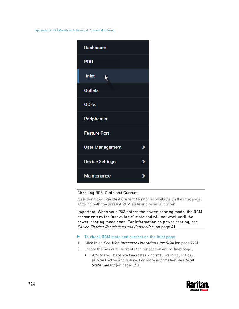
Appendix G: PX3 Models with Residual Current Monitoring
724
Checking RCM State and Current
A section titled 'Residual Current Monitor' is available on the Inlet page, showing both the present RCM state and residual current.
Important: When your PX3 enters the power-sharing mode, the RCM sensor enters the 'unavailable' state and will not work until the power-sharing mode ends. For information on power sharing, see Power-Sharing Restrictions and Connection (on page 41).
To check RCM state and current on the Inlet page: 1. Click Inlet. See Web Interface Operations for RCM (on page 723). 2. Locate the Residual Current Monitor section on the Inlet page.
RCM State: There are five states - normal, warning, critical, self-test active and failure. For more information, see RCM State Sensor (on page 721).
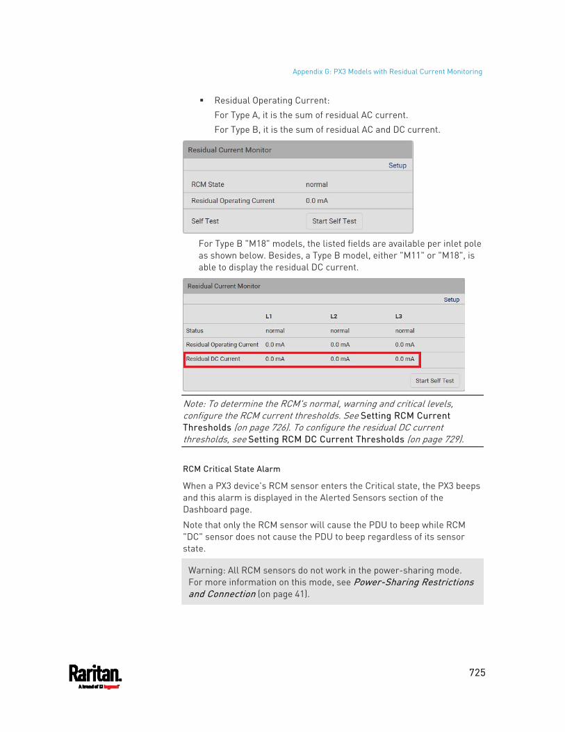
Appendix G: PX3 Models with Residual Current Monitoring
725
Residual Operating Current: For Type A, it is the sum of residual AC current. For Type B, it is the sum of residual AC and DC current.
For Type B "M18" models, the listed fields are available per inlet pole as shown below. Besides, a Type B model, either "M11" or "M18", is able to display the residual DC current.
Note: To determine the RCM's normal, warning and critical levels, configure the RCM current thresholds. See Setting RCM Current Thresholds (on page 726). To configure the residual DC current thresholds, see Setting RCM DC Current Thresholds (on page 729).
RCM Critical State Alarm
When a PX3 device's RCM sensor enters the Critical state, the PX3 beeps and this alarm is displayed in the Alerted Sensors section of the Dashboard page.
Note that only the RCM sensor will cause the PDU to beep while RCM "DC" sensor does not cause the PDU to beep regardless of its sensor state.
Warning: All RCM sensors do not work in the power-sharing mode. For more information on this mode, see Power-Sharing Restrictions and Connection (on page 41).
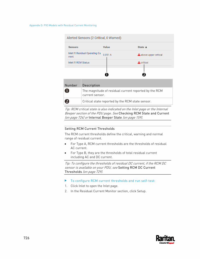
Appendix G: PX3 Models with Residual Current Monitoring
726
Number Description
The magnitude of residual current reported by the RCM current sensor.
Critical state reported by the RCM state sensor.
Tip: RCM critical state is also indicated on the Inlet page or the Internal Beeper section of the PDU page. See Checking RCM State and Current (on page 724) or Internal Beeper State (on page 159).
Setting RCM Current Thresholds
The RCM current thresholds define the critical, warning and normal range of residual current.
For Type A, RCM current thresholds are the thresholds of residual AC current.
For Type B, they are the thresholds of total residual current including AC and DC current.
Tip: To configure the thresholds of residual DC current, if the RCM DC sensor is available on your PDU, see Setting RCM DC Current Thresholds (on page 729).
To configure RCM current thresholds and run self-test: 1. Click Inlet to open the Inlet page. 2. In the Residual Current Monitor section, click Setup.
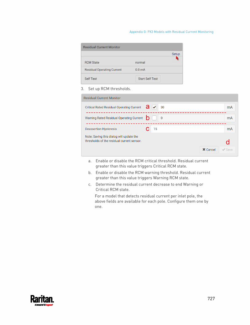
Appendix G: PX3 Models with Residual Current Monitoring
727
3. Set up RCM thresholds.
a. Enable or disable the RCM critical threshold. Residual current
greater than this value triggers Critical RCM state. b. Enable or disable the RCM warning threshold. Residual current
greater than this value triggers Warning RCM state. c. Determine the residual current decrease to end Warning or
Critical RCM state. For a model that detects residual current per inlet pole, the above fields are available for each pole. Configure them one by one.
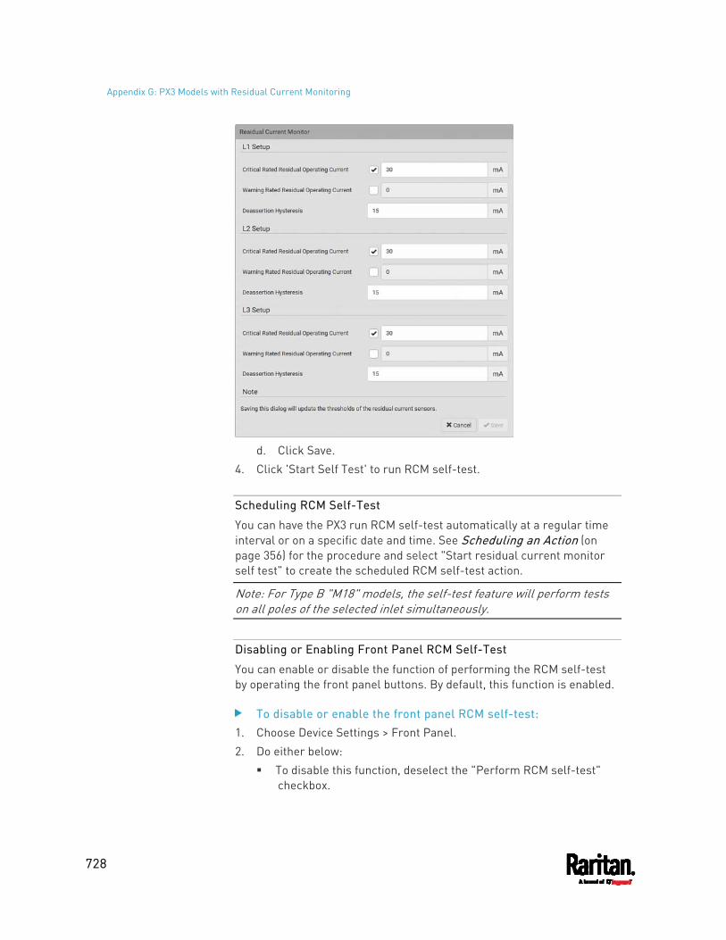
Appendix G: PX3 Models with Residual Current Monitoring
728
d. Click Save.
4. Click 'Start Self Test' to run RCM self-test.
Scheduling RCM Self-Test
You can have the PX3 run RCM self-test automatically at a regular time interval or on a specific date and time. See Scheduling an Action (on page 356) for the procedure and select "Start residual current monitor self test" to create the scheduled RCM self-test action.
Note: For Type B "M18" models, the self-test feature will perform tests on all poles of the selected inlet simultaneously.
Disabling or Enabling Front Panel RCM Self-Test
You can enable or disable the function of performing the RCM self-test by operating the front panel buttons. By default, this function is enabled.
To disable or enable the front panel RCM self-test: 1. Choose Device Settings > Front Panel. 2. Do either below:
To disable this function, deselect the "Perform RCM self-test" checkbox.
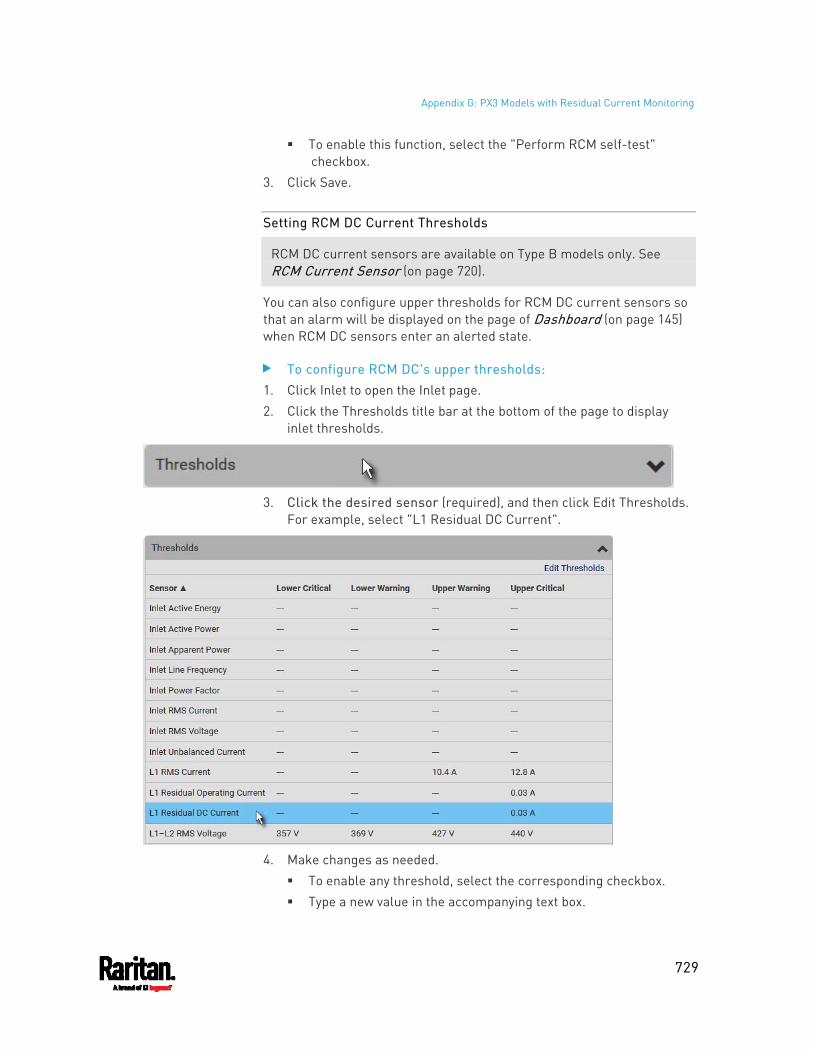
Appendix G: PX3 Models with Residual Current Monitoring
729
To enable this function, select the "Perform RCM self-test" checkbox.
3. Click Save.
Setting RCM DC Current Thresholds
RCM DC current sensors are available on Type B models only. See RCM Current Sensor (on page 720).
You can also configure upper thresholds for RCM DC current sensors so that an alarm will be displayed on the page of Dashboard (on page 145) when RCM DC sensors enter an alerted state.
To configure RCM DC's upper thresholds: 1. Click Inlet to open the Inlet page. 2. Click the Thresholds title bar at the bottom of the page to display
inlet thresholds.
3. Click the desired sensor (required), and then click Edit Thresholds.
For example, select "L1 Residual DC Current".
4. Make changes as needed.
To enable any threshold, select the corresponding checkbox. Type a new value in the accompanying text box.
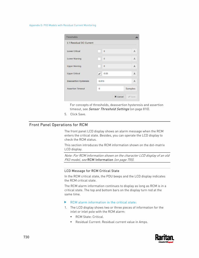
Appendix G: PX3 Models with Residual Current Monitoring
730
For concepts of thresholds, deassertion hysteresis and assertion timeout, see Sensor Threshold Settings (on page 810).
5. Click Save.
Front Panel Operations for RCM
The front panel LCD display shows an alarm message when the RCM enters the critical state. Besides, you can operate the LCD display to check the RCM status.
This section introduces the RCM information shown on the dot-matrix LCD display.
Note: For RCM information shown on the character LCD display of an old PX3 model, see RCM Information (on page 755).
LCD Message for RCM Critical State
In the RCM critical state, the PDU beeps and the LCD display indicates the RCM critical state.
The RCM alarm information continues to display as long as RCM is in a critical state. The top and bottom bars on the display turn red at the same time.
RCM alarm information in the critical state: 1. The LCD display shows two or three pieces of information for the
inlet or inlet pole with the RCM alarm: RCM State: Critical. Residual Current: Residual current value in Amps.
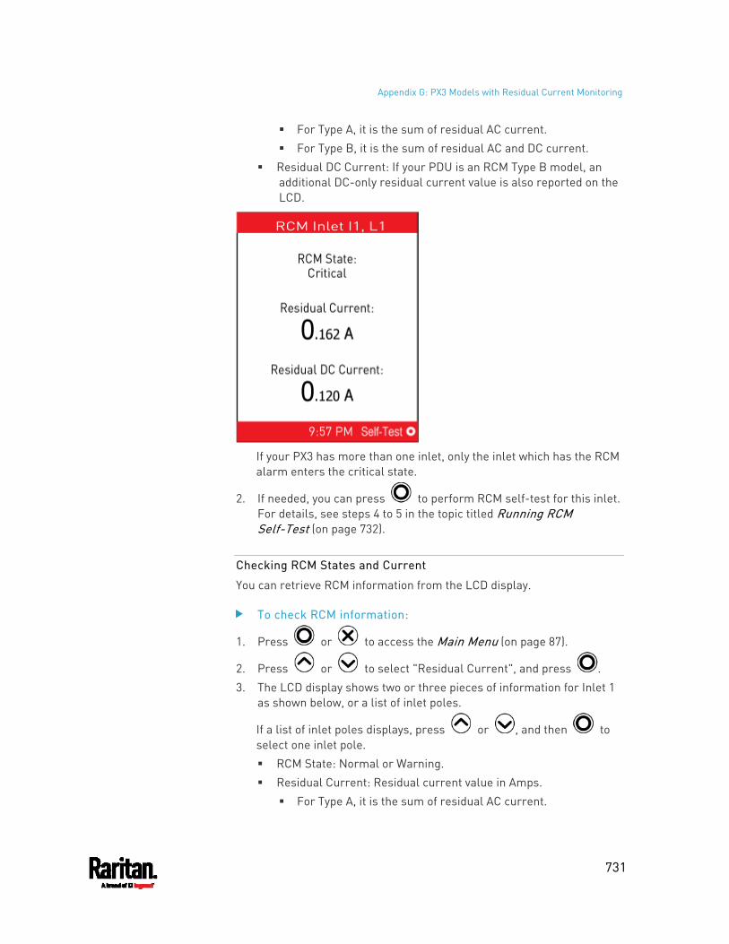
Appendix G: PX3 Models with Residual Current Monitoring
731
For Type A, it is the sum of residual AC current. For Type B, it is the sum of residual AC and DC current.
Residual DC Current: If your PDU is an RCM Type B model, an additional DC-only residual current value is also reported on the LCD.
If your PX3 has more than one inlet, only the inlet which has the RCM alarm enters the critical state.
2. If needed, you can press to perform RCM self-test for this inlet. For details, see steps 4 to 5 in the topic titled Running RCM Self-Test (on page 732).
Checking RCM States and Current
You can retrieve RCM information from the LCD display.
To check RCM information:
1. Press or to access the Main Menu (on page 87).
2. Press or to select "Residual Current", and press . 3. The LCD display shows two or three pieces of information for Inlet 1
as shown below, or a list of inlet poles.
If a list of inlet poles displays, press or , and then to select one inlet pole. RCM State: Normal or Warning. Residual Current: Residual current value in Amps.
For Type A, it is the sum of residual AC current.
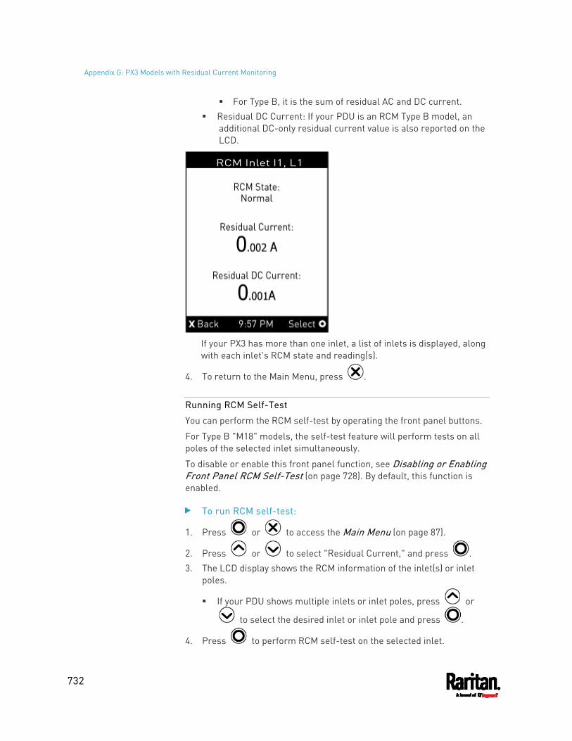
Appendix G: PX3 Models with Residual Current Monitoring
732
For Type B, it is the sum of residual AC and DC current. Residual DC Current: If your PDU is an RCM Type B model, an
additional DC-only residual current value is also reported on the LCD.
If your PX3 has more than one inlet, a list of inlets is displayed, along with each inlet's RCM state and reading(s).
4. To return to the Main Menu, press .
Running RCM Self-Test
You can perform the RCM self-test by operating the front panel buttons.
For Type B "M18" models, the self-test feature will perform tests on all poles of the selected inlet simultaneously.
To disable or enable this front panel function, see Disabling or Enabling Front Panel RCM Self-Test (on page 728). By default, this function is enabled.
To run RCM self-test:
1. Press or to access the Main Menu (on page 87).
2. Press or to select "Residual Current," and press . 3. The LCD display shows the RCM information of the inlet(s) or inlet
poles.
If your PDU shows multiple inlets or inlet poles, press or
to select the desired inlet or inlet pole and press .
4. Press to perform RCM self-test on the selected inlet.
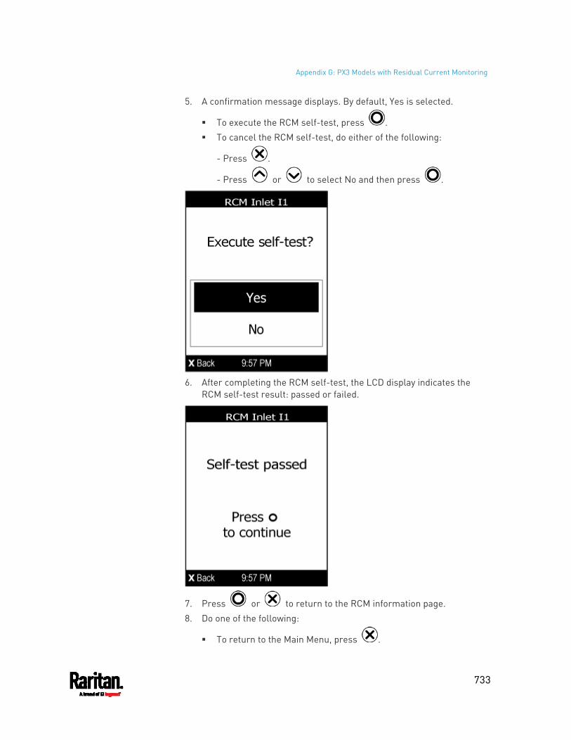
Appendix G: PX3 Models with Residual Current Monitoring
733
5. A confirmation message displays. By default, Yes is selected.
To execute the RCM self-test, press . To cancel the RCM self-test, do either of the following:
- Press .
- Press or to select No and then press .
6. After completing the RCM self-test, the LCD display indicates the
RCM self-test result: passed or failed.
7. Press or to return to the RCM information page. 8. Do one of the following:
To return to the Main Menu, press .
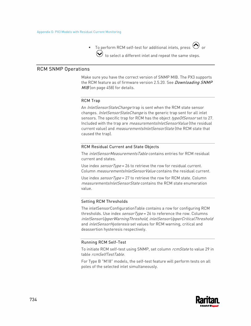
Appendix G: PX3 Models with Residual Current Monitoring
734
To perform RCM self-test for additional inlets, press or
to select a different inlet and repeat the same steps.
RCM SNMP Operations
Make sure you have the correct version of SNMP MIB. The PX3 supports the RCM feature as of firmware version 2.5.20. See Downloading SNMP MIB (on page 458) for details.
RCM Trap
An InletSensorStateChange trap is sent when the RCM state sensor changes. InletSensorStateChange is the generic trap sent for all inlet sensors. The specific trap for RCM has the object typeOfSensor set to 27. Included with the trap are measurementsInletSensorValue (the residual current value) and measurementsInletSensorState (the RCM state that caused the trap).
RCM Residual Current and State Objects
The inletSensorMeasurementsTable contains entries for RCM residual current and states.
Use index sensorType = 26 to retrieve the row for residual current. Column measurementsInletSensorValue contains the residual current.
Use index sensorType = 27 to retrieve the row for RCM state. Column measurementsInletSensorState contains the RCM state enumeration value.
Setting RCM Thresholds
The inletSensorConfigurationTable contains a row for configuring RCM thresholds. Use index sensorType = 26 to reference the row. Columns inletSensorUpperWarningThreshold, inletSensorUpperCriticalThreshold and inletSensorHysteresis set values for RCM warning, critical and deassertion hysteresis respectively.
Running RCM Self-Test
To initiate RCM self-test using SNMP, set column rcmState to value 29 in table rcmSelfTestTable.
For Type B "M18" models, the self-test feature will perform tests on all poles of the selected inlet simultaneously.
Appendix G: PX3 Models with Residual Current Monitoring
735
CLI Operations for RCM
For information on entering and using the CLI, see Using the Command Line Interface (on page 462).
Showing Residual Current Monitoring Information
This command syntax shows the residual current monitoring (RCM) information, which is only available on the models with RCM. The information displayed include the RCM current, state and thresholds.
For Type B "M18" models, this command shows the information of all RCM sensors of the same inlet at a time.
# show residualCurrentMonitor <n>
Variables: <n> is one of the options: all, or a number.
Option Description
all Displays the RCM information of all inlets.
Tip: You can also type the command without adding this option "all" to get the same data.
A specific inlet number
Displays the RCM information of the specified inlet only. An inlet number needs to be specified only when there are more than 1 inlet on your PDU.
Tip -- other RCM-related "show" commands: For models detecting residual current per inlet, see Inlet Sensor
Threshold Information (on page 482) For models detecting residual current per inlet pole, see Inlet Pole
Sensor Threshold Information (on page 484)
Setting RCM Current Thresholds
Warning Rated Residual Operating Current is the upper warning threshold of the PX3 RCM sensor, and Critical Rated Residual Operating Current is the upper critical threshold of the RCM sensor. These thresholds are set in the configuration mode. See Entering Configuration Mode (on page 500).
Appendix G: PX3 Models with Residual Current Monitoring
736
Note: A residual current sensor's LOWER warning and LOWER critical thresholds do NOT affect the operations of the RCM state sensor so you can ignore them.
For Type B "M18" models, this command configures all RCM sensors of the same inlet simultaneously.
To configure the RCM's Critical level:
config:# residualCurrentMonitor <n> criticalRatedResidualOperatingCurrent <value>
Note: The PX3 triggers events when residual current values are above (but not equal to) thresholds. For example, you would set the critical threshold to 29mA to specify the IEC 62020 IΔn of 30mA. See Compliance with IEC 62020 (on page 722).
To configure the RCM's Warning level:
config:# residualCurrentMonitor <n> warningRatedResidualOperatingCurrent <value>
To configure the RCM's deassertion hysteresis:
config:# residualCurrentMonitor <n> deassertionHysteresis <hy_value>
Variables: <n> is the number of the inlet where the desired RCM current sensor
is mounted. For a single-inlet PDU, this number is always 1. <value> is one of the options: enable, disable or a numeric value
measured in amperes.
Option Description
enable Enables the specified RCM current threshold for the specified inlet.
disable Disables the specified RCM current threshold for the specified inlet.
A numeric value
Sets a value for the specified RCM current threshold of the specified inlet and enables this threshold simultaneously.
Note that this value is measured in A, not mA. Therefore, to set the value to 6mA, type 0.006.
Appendix G: PX3 Models with Residual Current Monitoring
737
<hy_value> is a numeric value measured in amperes (A), not milliamperes (mA). For example, to set the value to 15mA, type 0.015.
Tip -- other RCM-related "threshold-setting" commands: For models detecting residual current per inlet, see Commands for
Inlet Sensors (on page 602) For models detecting residual current per inlet pole, see Commands
for Inlet Pole Sensors (on page 604)
Setting Front Panel RCM Self-Test
You can enable or disable the front panel RCM self-test function via CLI in addition to the web interface.
To enable the front panel RCM self-test:
# security frontPanelPermissions add rcmSelfTest
To disable the front panel RCM self-test:
# security frontPanelPermissions remove rcmSelfTest
Running RCM Self-Test
You can perform RCM self-test for a specific inlet via CLI. After the self-test finishes, the test result is shown: pass or fail.
For Type B "M18" models, the self-test feature will perform tests on all poles of the selected inlet simultaneously.
To perform RCM self-test:
# rcm selfTest inlet <n>
Variables: <n> is the inlet's number. For a single-inlet PDU, <n> is always 1.
Degaussing RCM Type B Sensors
Only the models with RCM 'Type B' sensors support degaussing the RCM sensors. Those with RCM Type A sensors do NOT support this feature.
You can degauss the RCM sensor after a current surge, such as a short circuit.

Appendix G: PX3 Models with Residual Current Monitoring
738
For Type B "M18" models, this command will degauss all RCM sensors simultaneously.
To degauss RCM Type B sensors:
# rcm degauss
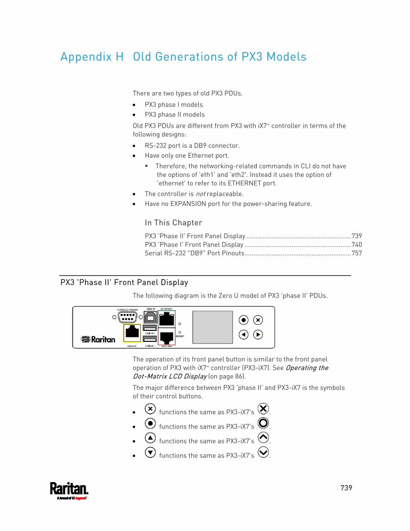
739
There are two types of old PX3 PDUs.
PX3 phase I models PX3 phase II models
Old PX3 PDUs are different from PX3 with iX7™ controller in terms of the following designs:
RS-232 port is a DB9 connector. Have only one Ethernet port.
Therefore, the networking-related commands in CLI do not have the options of 'eth1' and 'eth2'. Instead it uses the option of 'ethernet' to refer to its ETHERNET port.
The controller is not replaceable. Have no EXPANSION port for the power-sharing feature.
In This Chapter
PX3 'Phase II' Front Panel Display ..........................................................739 PX3 'Phase I' Front Panel Display ...........................................................740 Serial RS-232 "DB9" Port Pinouts...........................................................757
PX3 'Phase II' Front Panel Display
The following diagram is the Zero U model of PX3 'phase II' PDUs.
The operation of its front panel button is similar to the front panel operation of PX3 with iX7™ controller (PX3-iX7). See Operating the Dot-Matrix LCD Display (on page 86).
The major difference between PX3 'phase II' and PX3-iX7 is the symbols of their control buttons.
functions the same as PX3-iX7's .
functions the same as PX3-iX7's .
functions the same as PX3-iX7's .
functions the same as PX3-iX7's .
Appendix H Old Generations of PX3 Models
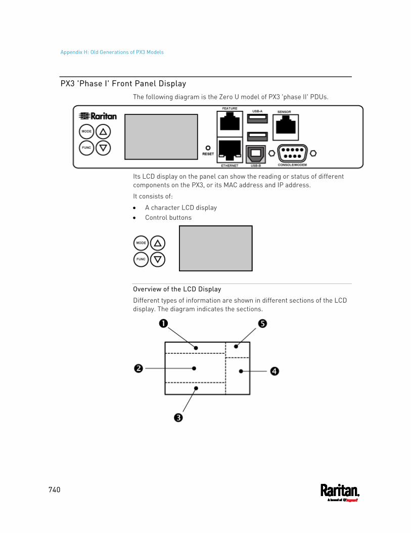
Appendix H: Old Generations of PX3 Models
740
PX3 'Phase I' Front Panel Display
The following diagram is the Zero U model of PX3 'phase II' PDUs.
Its LCD display on the panel can show the reading or status of different components on the PX3, or its MAC address and IP address.
It consists of:
A character LCD display Control buttons
Overview of the LCD Display
Different types of information are shown in different sections of the LCD display. The diagram indicates the sections.
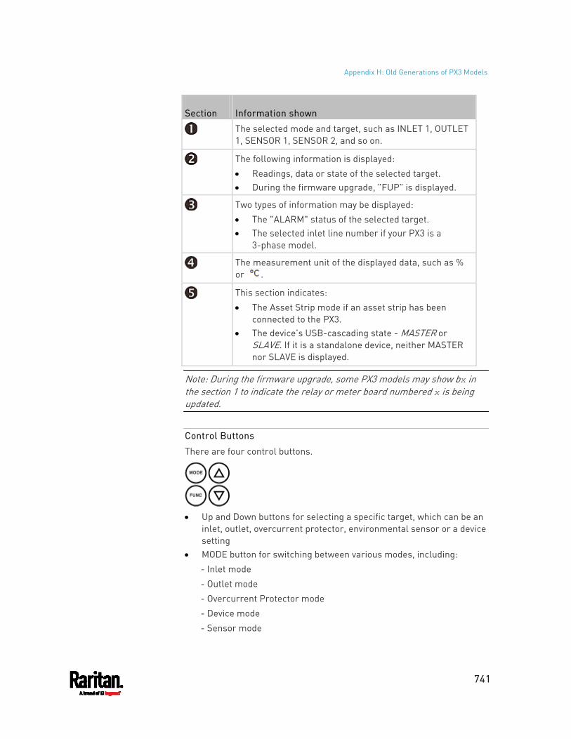
Appendix H: Old Generations of PX3 Models
741
Section Information shown
The selected mode and target, such as INLET 1, OUTLET 1, SENSOR 1, SENSOR 2, and so on.
The following information is displayed: Readings, data or state of the selected target. During the firmware upgrade, "FUP" is displayed.
Two types of information may be displayed: The "ALARM" status of the selected target. The selected inlet line number if your PX3 is a
3-phase model.
The measurement unit of the displayed data, such as % or .
This section indicates: The Asset Strip mode if an asset strip has been
connected to the PX3. The device's USB-cascading state - MASTER or
SLAVE. If it is a standalone device, neither MASTER nor SLAVE is displayed.
Note: During the firmware upgrade, some PX3 models may show bx in the section 1 to indicate the relay or meter board numbered x is being updated.
Control Buttons
There are four control buttons.
Up and Down buttons for selecting a specific target, which can be an
inlet, outlet, overcurrent protector, environmental sensor or a device setting
MODE button for switching between various modes, including: - Inlet mode - Outlet mode - Overcurrent Protector mode - Device mode - Sensor mode
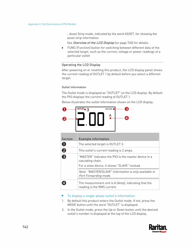
Appendix H: Old Generations of PX3 Models
742
- Asset Strip mode, indicated by the word ASSET, for showing the asset strip information See Overview of the LCD Display (on page 740) for details.
FUNC (Function) button for switching between different data of the selected target, such as the current, voltage or power readings of a particular outlet
Operating the LCD Display
After powering on or resetting this product, the LCD display panel shows the current reading of OUTLET 1 by default before you select a different target.
Outlet Information
The Outlet mode is displayed as "OUTLET" on the LCD display. By default the PX3 displays the current reading of OUTLET 1.
Below illustrates the outlet information shown on the LCD display.
Section Example information
The selected target is OUTLET 3.
This outlet's current reading is 2 amps.
"MASTER" indicates the PX3 is the master device in a cascading chain. For a slave device, it shows "SLAVE" instead.
Note: "MASTER/SLAVE" information is only available in Port Forwarding mode.
The measurement unit is A (Amp), indicating that the reading is the RMS current.
To display a single-phase outlet's information: 1. By default this product enters the Outlet mode. If not, press the
MODE button until the word "OUTLET" is displayed. 2. In the Outlet mode, press the Up or Down button until the desired
outlet's number is displayed at the top of the LCD display.
Appendix H: Old Generations of PX3 Models
743
3. Press the FUNC button to switch between voltage, active power and current readings of the selected target. A is displayed for the current reading. A means Amp. V is displayed for the voltage reading. V means Volt. W is displayed for the power reading. W means Watt. If the word "ALARM" appears below the reading, it means the currently displayed reading already reaches or crosses the upper or lower thresholds.
To display a 3-phase outlet's information 1. In the Outlet mode, press the Up or Down button until the desired
3-phase outlet is selected. 2. While that 3-phase outlet is being selected, press the Up or Down
button to switch between each line, indicated as L1, L2 or L3 at the bottom of the display.
3. When the desired line is being displayed, press the FUNC button to switch between voltage, active power and current readings of this particular line. A is displayed for the current reading. A means Amp. V is displayed for the voltage reading. V means Volt. When voltage
is selected, L1-L2, L2-L3, or L3-L1 is displayed at the bottom of the display.
W is displayed for the power reading. W means Watt. 4. To show the unbalanced load and active power of this 3-phase outlet,
do the following: a. Switch to the current reading of L1. b. Press the Down button until '%' or 'W' is displayed to the right of
the display. Make sure NONE of the lines (L1, L2, L3, L1-L2, L2-L3 or L3-L1) is displayed at the bottom of the display. Unbalanced load - % is displayed for the unbalanced current
value. Active power - W is displayed for the power reading. W
means Watt.
Inlet Information
The Inlet mode is displayed as "INLET" on the LCD display. Below illustrates the inlet information shown on the LCD display.
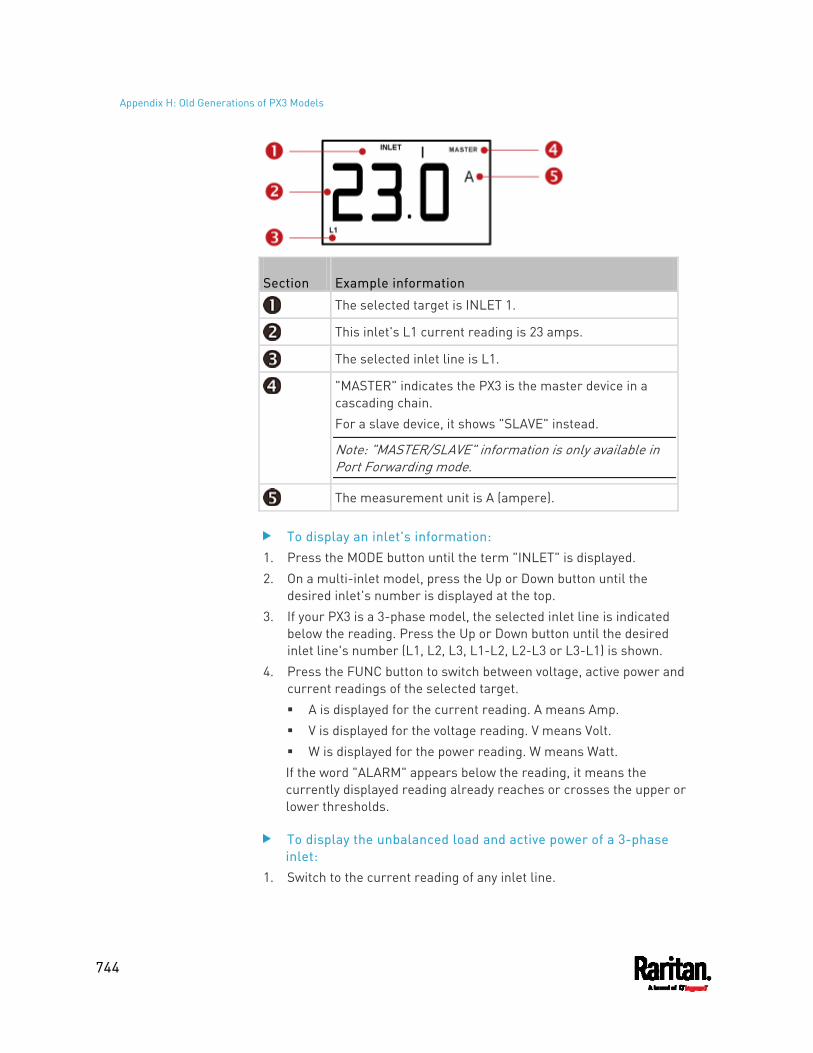
Appendix H: Old Generations of PX3 Models
744
Section Example information
The selected target is INLET 1.
This inlet's L1 current reading is 23 amps.
The selected inlet line is L1.
"MASTER" indicates the PX3 is the master device in a cascading chain. For a slave device, it shows "SLAVE" instead.
Note: "MASTER/SLAVE" information is only available in Port Forwarding mode.
The measurement unit is A (ampere).
To display an inlet's information: 1. Press the MODE button until the term "INLET" is displayed. 2. On a multi-inlet model, press the Up or Down button until the
desired inlet's number is displayed at the top. 3. If your PX3 is a 3-phase model, the selected inlet line is indicated
below the reading. Press the Up or Down button until the desired inlet line's number (L1, L2, L3, L1-L2, L2-L3 or L3-L1) is shown.
4. Press the FUNC button to switch between voltage, active power and current readings of the selected target. A is displayed for the current reading. A means Amp. V is displayed for the voltage reading. V means Volt. W is displayed for the power reading. W means Watt. If the word "ALARM" appears below the reading, it means the currently displayed reading already reaches or crosses the upper or lower thresholds.
To display the unbalanced load and active power of a 3-phase inlet:
1. Switch to the current reading of any inlet line.
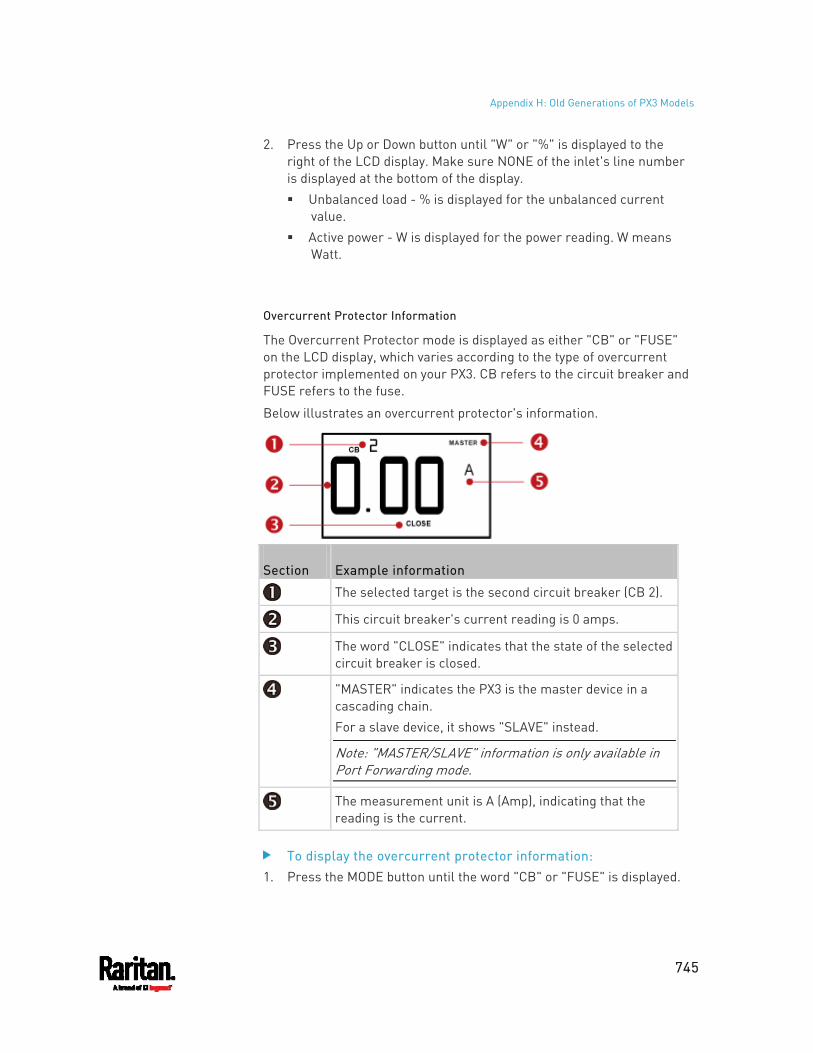
Appendix H: Old Generations of PX3 Models
745
2. Press the Up or Down button until "W" or "%" is displayed to the right of the LCD display. Make sure NONE of the inlet's line number is displayed at the bottom of the display. Unbalanced load - % is displayed for the unbalanced current
value. Active power - W is displayed for the power reading. W means
Watt.
Overcurrent Protector Information
The Overcurrent Protector mode is displayed as either "CB" or "FUSE" on the LCD display, which varies according to the type of overcurrent protector implemented on your PX3. CB refers to the circuit breaker and FUSE refers to the fuse.
Below illustrates an overcurrent protector's information.
Section Example information
The selected target is the second circuit breaker (CB 2).
This circuit breaker's current reading is 0 amps.
The word "CLOSE" indicates that the state of the selected circuit breaker is closed.
"MASTER" indicates the PX3 is the master device in a cascading chain. For a slave device, it shows "SLAVE" instead.
Note: "MASTER/SLAVE" information is only available in Port Forwarding mode.
The measurement unit is A (Amp), indicating that the reading is the current.
To display the overcurrent protector information: 1. Press the MODE button until the word "CB" or "FUSE" is displayed.
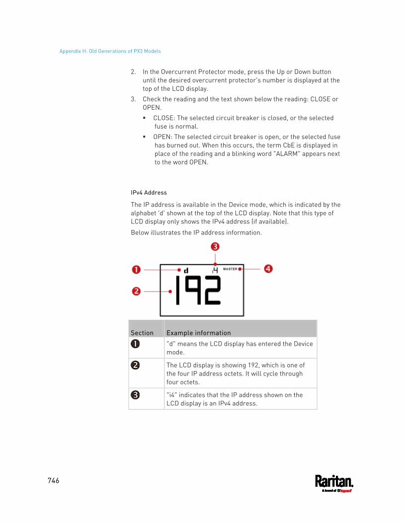
Appendix H: Old Generations of PX3 Models
746
2. In the Overcurrent Protector mode, press the Up or Down button until the desired overcurrent protector's number is displayed at the top of the LCD display.
3. Check the reading and the text shown below the reading: CLOSE or OPEN. CLOSE: The selected circuit breaker is closed, or the selected
fuse is normal. OPEN: The selected circuit breaker is open, or the selected fuse
has burned out. When this occurs, the term CbE is displayed in place of the reading and a blinking word "ALARM" appears next to the word OPEN.
IPv4 Address
The IP address is available in the Device mode, which is indicated by the alphabet 'd' shown at the top of the LCD display. Note that this type of LCD display only shows the IPv4 address (if available).
Below illustrates the IP address information.
Section Example information
"d" means the LCD display has entered the Device mode.
The LCD display is showing 192, which is one of the four IP address octets. It will cycle through four octets.
"i4" indicates that the IP address shown on the LCD display is an IPv4 address.
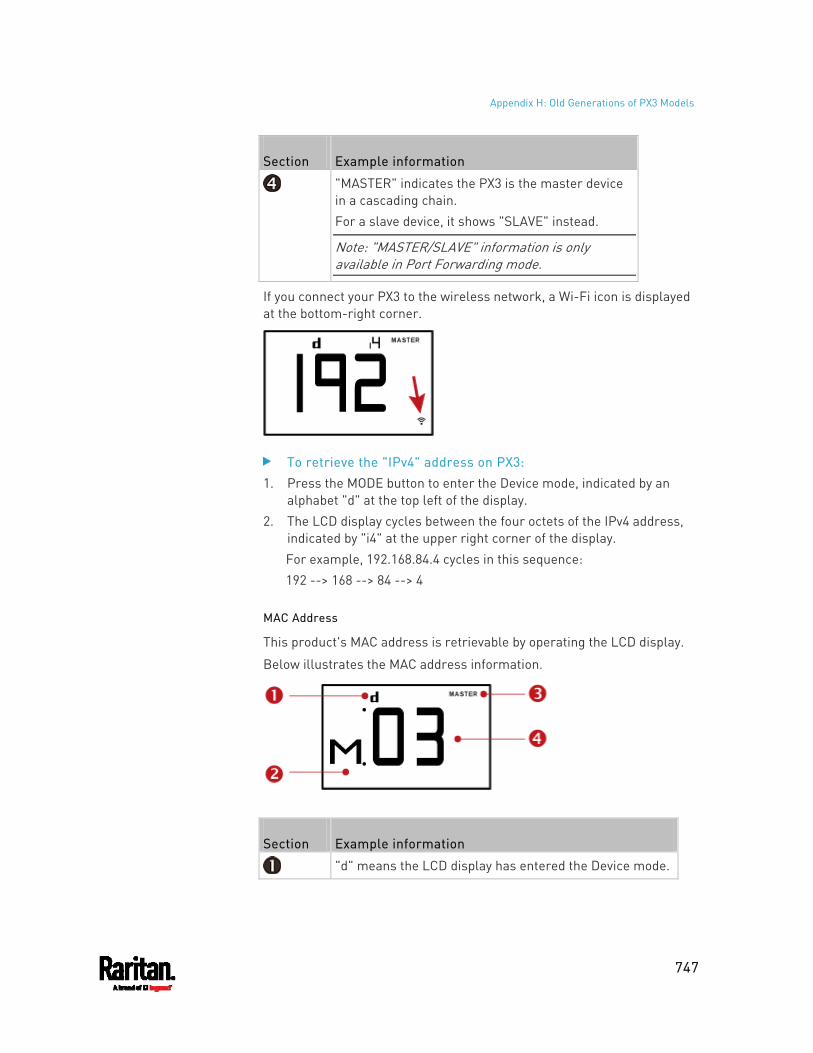
Appendix H: Old Generations of PX3 Models
747
Section Example information
"MASTER" indicates the PX3 is the master device in a cascading chain. For a slave device, it shows "SLAVE" instead.
Note: "MASTER/SLAVE" information is only available in Port Forwarding mode.
If you connect your PX3 to the wireless network, a Wi-Fi icon is displayed at the bottom-right corner.
To retrieve the "IPv4" address on PX3: 1. Press the MODE button to enter the Device mode, indicated by an
alphabet "d" at the top left of the display. 2. The LCD display cycles between the four octets of the IPv4 address,
indicated by "i4" at the upper right corner of the display. For example, 192.168.84.4 cycles in this sequence: 192 --> 168 --> 84 --> 4
MAC Address
This product's MAC address is retrievable by operating the LCD display.
Below illustrates the MAC address information.
Section Example information
"d" means the LCD display has entered the Device mode.
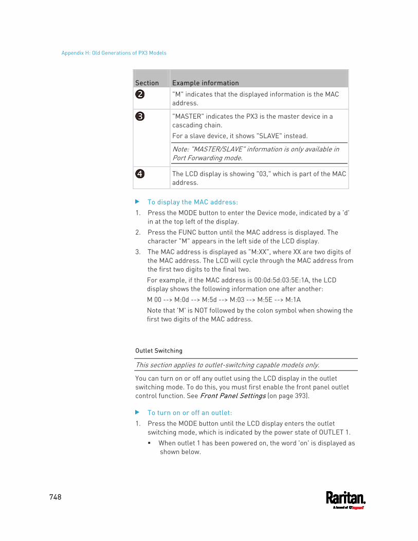
Appendix H: Old Generations of PX3 Models
748
Section Example information
"M" indicates that the displayed information is the MAC address.
"MASTER" indicates the PX3 is the master device in a cascading chain. For a slave device, it shows "SLAVE" instead.
Note: "MASTER/SLAVE" information is only available in Port Forwarding mode.
The LCD display is showing "03," which is part of the MAC address.
To display the MAC address: 1. Press the MODE button to enter the Device mode, indicated by a 'd'
in at the top left of the display. 2. Press the FUNC button until the MAC address is displayed. The
character "M" appears in the left side of the LCD display. 3. The MAC address is displayed as "M:XX", where XX are two digits of
the MAC address. The LCD will cycle through the MAC address from the first two digits to the final two. For example, if the MAC address is 00:0d:5d:03:5E:1A, the LCD display shows the following information one after another: M 00 --> M:0d --> M:5d --> M:03 --> M:5E --> M:1A Note that 'M' is NOT followed by the colon symbol when showing the first two digits of the MAC address.
Outlet Switching
This section applies to outlet-switching capable models only.
You can turn on or off any outlet using the LCD display in the outlet switching mode. To do this, you must first enable the front panel outlet control function. See Front Panel Settings (on page 393).
To turn on or off an outlet: 1. Press the MODE button until the LCD display enters the outlet
switching mode, which is indicated by the power state of OUTLET 1. When outlet 1 has been powered on, the word 'on' is displayed as
shown below.

Appendix H: Old Generations of PX3 Models
749
When outlet 1 has been powered off, the word "oFF" is displayed
instead. 2. Press the Up or Down button to select the desired outlet. The
selected outlet's number is displayed at the top of the LCD display. 3. Press the FUNC button to perform the outlet switching operation.
The LCD display cycles between two messages as shown in the two diagrams below. In the following diagrams, X represents the selected outlet's number.
To cancel the outlet switching operation, press the FUNC button again.
4. To turn on the outlet, press the Up button. The "on?" confirmation message displays.
To turn off the outlet, press the Down button. The "oF?" confirmation message displays.
5. Press the same button as step 4 again to confirm the operation.
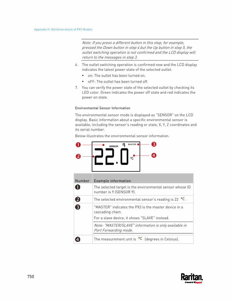
Appendix H: Old Generations of PX3 Models
750
Note: If you press a different button in this step, for example, pressed the Down button in step 4 but the Up button in step 5, the outlet switching operation is not confirmed and the LCD display will return to the messages in step 3.
6. The outlet switching operation is confirmed now and the LCD display indicates the latest power state of the selected outlet. on: The outlet has been turned on. oFF: The outlet has been turned off.
7. You can verify the power state of the selected outlet by checking its LED color. Green indicates the power off state and red indicates the power on state.
Environmental Sensor Information
The environmental sensor mode is displayed as "SENSOR" on the LCD display. Basic information about a specific environmental sensor is available, including the sensor's reading or state, X, Y, Z coordinates and its serial number.
Below illustrates the environmental sensor information.
Number Example information
The selected target is the environmental sensor whose ID number is 9 (SENSOR 9).
The selected environmental sensor's reading is 22 .
"MASTER" indicates the PX3 is the master device in a cascading chain. For a slave device, it shows "SLAVE" instead.
Note: "MASTER/SLAVE" information is only available in Port Forwarding mode.
The measurement unit is (degrees in Celsius).
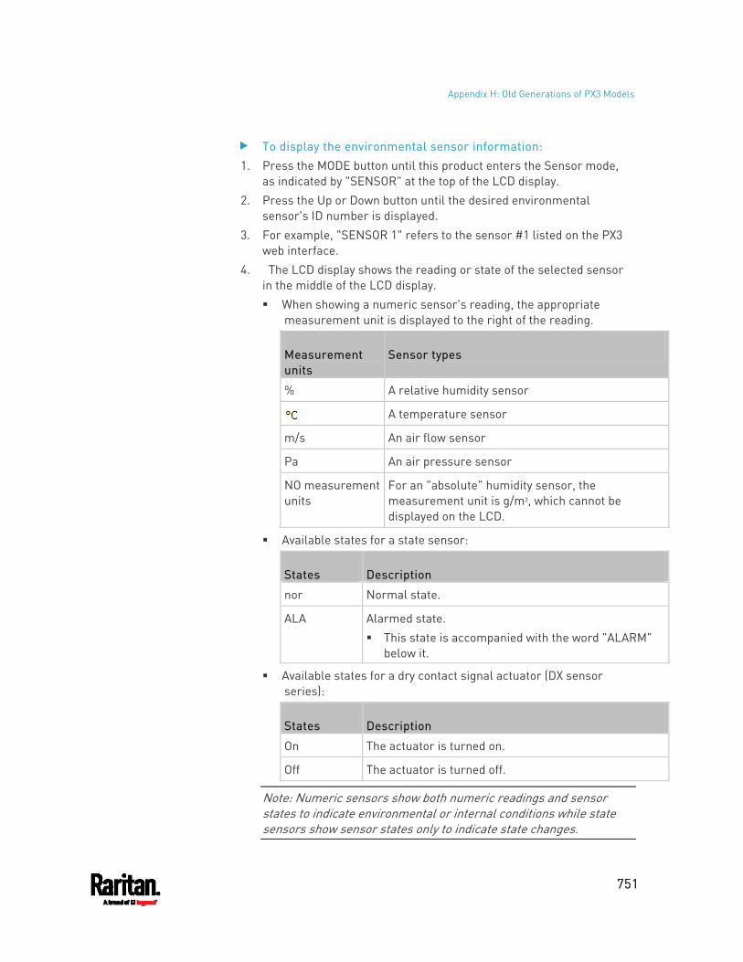
Appendix H: Old Generations of PX3 Models
751
To display the environmental sensor information: 1. Press the MODE button until this product enters the Sensor mode,
as indicated by "SENSOR" at the top of the LCD display. 2. Press the Up or Down button until the desired environmental
sensor's ID number is displayed. 3. For example, "SENSOR 1" refers to the sensor #1 listed on the PX3
web interface. 4. The LCD display shows the reading or state of the selected sensor
in the middle of the LCD display. When showing a numeric sensor's reading, the appropriate
measurement unit is displayed to the right of the reading.
Measurement units
Sensor types
% A relative humidity sensor
A temperature sensor
m/s An air flow sensor
Pa An air pressure sensor
NO measurement units
For an "absolute" humidity sensor, the measurement unit is g/m3, which cannot be displayed on the LCD.
Available states for a state sensor:
States Description
nor Normal state.
ALA Alarmed state. This state is accompanied with the word "ALARM"
below it.
Available states for a dry contact signal actuator (DX sensor series):
States Description
On The actuator is turned on.
Off The actuator is turned off.
Note: Numeric sensors show both numeric readings and sensor states to indicate environmental or internal conditions while state sensors show sensor states only to indicate state changes.
Appendix H: Old Generations of PX3 Models
752
5. Press the FUNC button to show the sensor's port position. There are two types of information. P:n (where n is the SENSOR port's number): This information
indicates the SENSOR port number. C:x (where x is the sensor's position in a sensor chain): This
information indicates the sensor's position in a chain, which is available for DPX2, DPX3 and DX sensors only. The LCD display will cycle between the port information (P:n) and chain position information (C:x). Note that if the DPX3-ENVHUB4 sensor hub is used to connect the DPX2, DPX3 or DX sensors, the chain position information (C:x) is displayed twice - the first one indicates the sensor hub's chain position, which is always C:1, and the second one indicates the sensor's chain position.
6. Press the FUNC button to display the X, Y and Z coordinates of the sensor respectively. X coordinate is shown as "x:NN," where NN are the first two
numeric digits entered for the X coordinate in the web interface. Y coordinate is shown as "y:NN," where NN are the first two
numeric digits entered for the Y coordinate in the web interface. Z coordinate is shown as "z:NN," where NN are the first two
numeric digits entered for the Z coordinate in the web interface. If one or both of the first two digits for a specific coordinate are alphabetical characters, these alphabetical characters are replaced with dashes (-).
7. Press the FUNC button to display the serial number of the sensor, which is shown as "s:XX," where XX are two digits of the serial number. The LCD will cycle through the serial number from the first two digits to the final two. For example, if the serial number is AE17A00022, the LCD display shows the following information one after another: s:AE --> s:17 --> s:A0 --> s:00 --> s:22
Note: Some alphabets cannot be properly displayed due to the LCD display restriction. For example, Q looks like 9, Z looks like 2, and M looks like . Check the sensor's label or the web interface when you have doubts.
Asset Strip Information
If there is any asset strip connected to the PX3, you can enter the Asset Strip mode to show the asset tag state of each rack unit on the asset strip. A rack unit refers to a tag port on the asset strips.
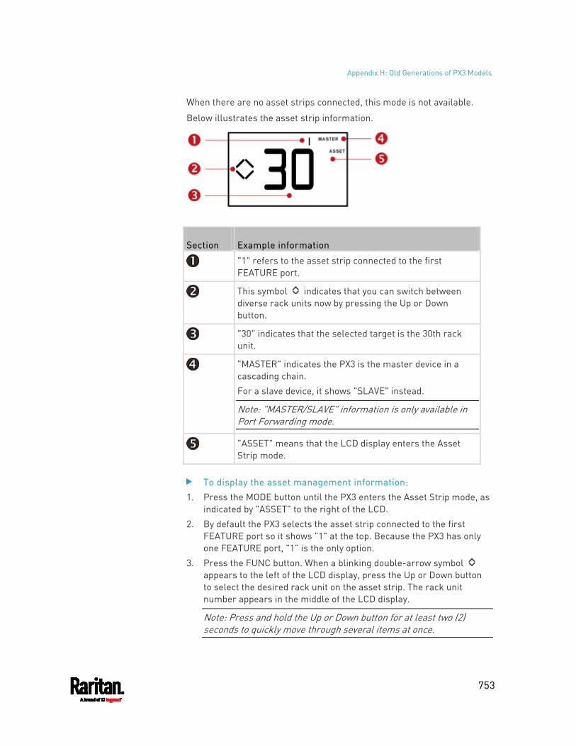
Appendix H: Old Generations of PX3 Models
753
When there are no asset strips connected, this mode is not available.
Below illustrates the asset strip information.
Section Example information
"1" refers to the asset strip connected to the first FEATURE port.
This symbol indicates that you can switch between diverse rack units now by pressing the Up or Down button.
"30" indicates that the selected target is the 30th rack unit.
"MASTER" indicates the PX3 is the master device in a cascading chain. For a slave device, it shows "SLAVE" instead.
Note: "MASTER/SLAVE" information is only available in Port Forwarding mode.
"ASSET" means that the LCD display enters the Asset Strip mode.
To display the asset management information: 1. Press the MODE button until the PX3 enters the Asset Strip mode, as
indicated by "ASSET" to the right of the LCD. 2. By default the PX3 selects the asset strip connected to the first
FEATURE port so it shows "1" at the top. Because the PX3 has only one FEATURE port, "1" is the only option.
3. Press the FUNC button. When a blinking double-arrow symbol appears to the left of the LCD display, press the Up or Down button to select the desired rack unit on the asset strip. The rack unit number appears in the middle of the LCD display.
Note: Press and hold the Up or Down button for at least two (2) seconds to quickly move through several items at once.
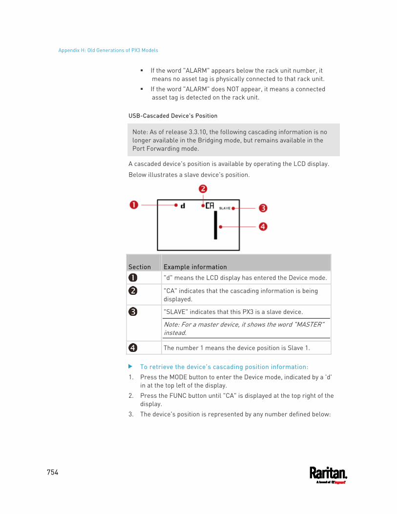
Appendix H: Old Generations of PX3 Models
754
If the word "ALARM" appears below the rack unit number, it means no asset tag is physically connected to that rack unit.
If the word "ALARM" does NOT appear, it means a connected asset tag is detected on the rack unit.
USB-Cascaded Device's Position
Note: As of release 3.3.10, the following cascading information is no longer available in the Bridging mode, but remains available in the Port Forwarding mode.
A cascaded device's position is available by operating the LCD display.
Below illustrates a slave device's position.
Section Example information
"d" means the LCD display has entered the Device mode.
"CA" indicates that the cascading information is being displayed.
"SLAVE" indicates that this PX3 is a slave device.
Note: For a master device, it shows the word "MASTER" instead.
The number 1 means the device position is Slave 1.
To retrieve the device's cascading position information: 1. Press the MODE button to enter the Device mode, indicated by a 'd'
in at the top left of the display. 2. Press the FUNC button until "CA" is displayed at the top right of the
display. 3. The device's position is represented by any number defined below:
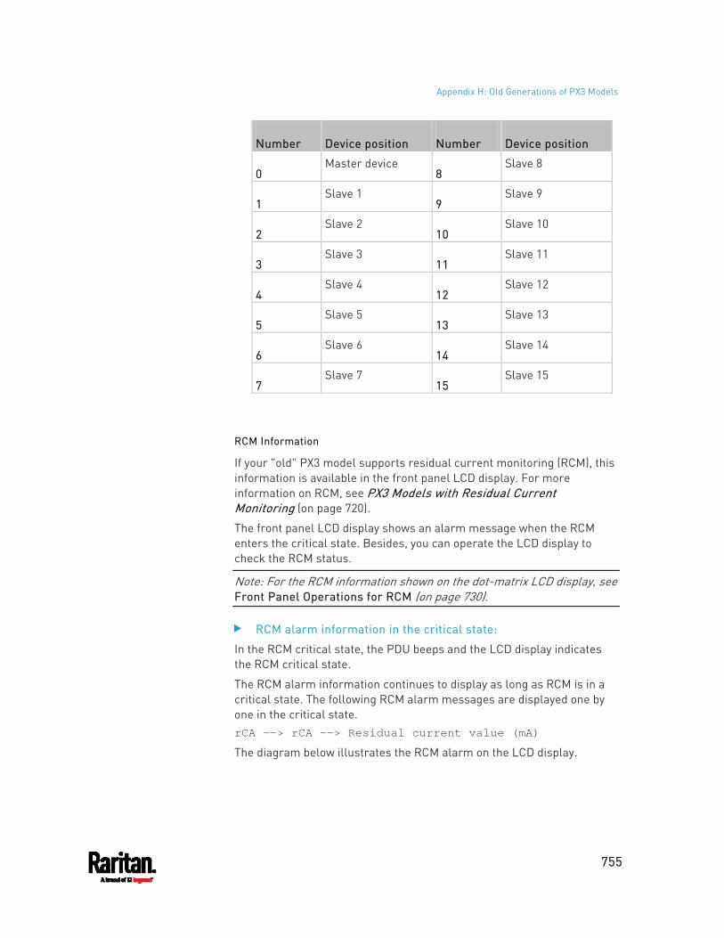
Appendix H: Old Generations of PX3 Models
755
Number Device position Number Device position
0 Master device
8 Slave 8
1 Slave 1
9 Slave 9
2 Slave 2
10 Slave 10
3 Slave 3
11 Slave 11
4 Slave 4
12 Slave 12
5 Slave 5
13 Slave 13
6 Slave 6
14 Slave 14
7 Slave 7
15 Slave 15
RCM Information
If your "old" PX3 model supports residual current monitoring (RCM), this information is available in the front panel LCD display. For more information on RCM, see PX3 Models with Residual Current Monitoring (on page 720).
The front panel LCD display shows an alarm message when the RCM enters the critical state. Besides, you can operate the LCD display to check the RCM status.
Note: For the RCM information shown on the dot-matrix LCD display, see Front Panel Operations for RCM (on page 730).
RCM alarm information in the critical state:
In the RCM critical state, the PDU beeps and the LCD display indicates the RCM critical state.
The RCM alarm information continues to display as long as RCM is in a critical state. The following RCM alarm messages are displayed one by one in the critical state. rCA --> rCA --> Residual current value (mA)
The diagram below illustrates the RCM alarm on the LCD display.
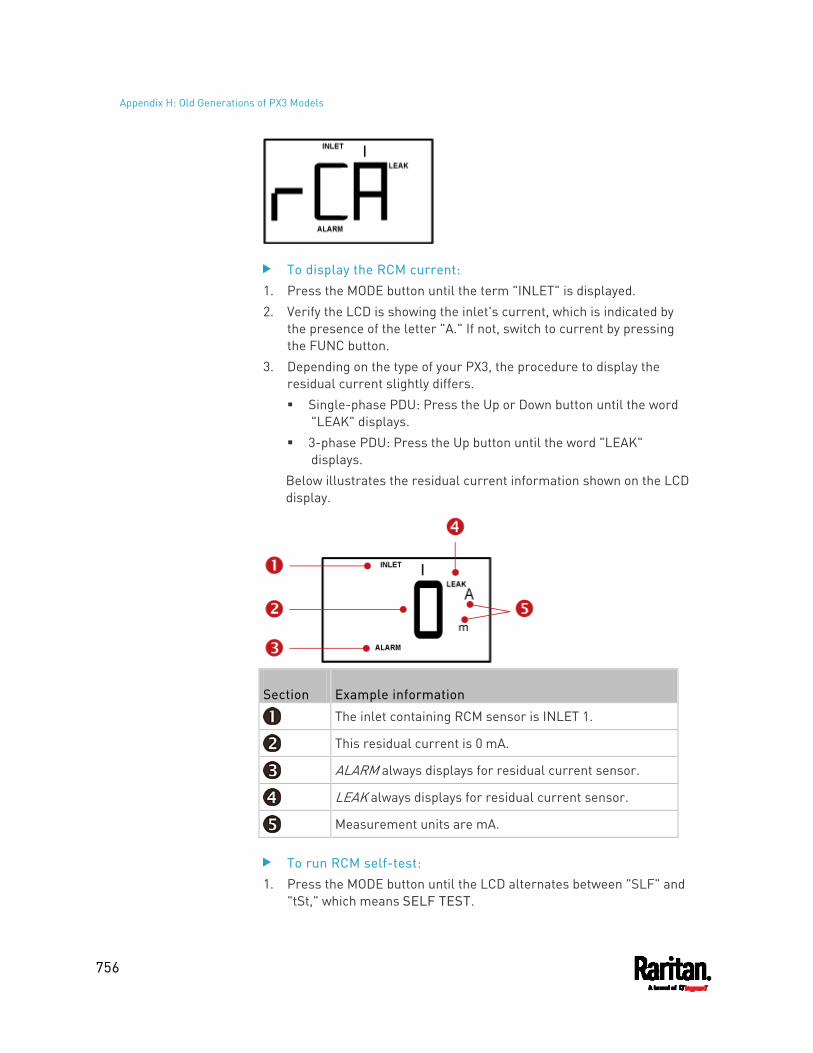
Appendix H: Old Generations of PX3 Models
756
To display the RCM current: 1. Press the MODE button until the term "INLET" is displayed. 2. Verify the LCD is showing the inlet's current, which is indicated by
the presence of the letter "A." If not, switch to current by pressing the FUNC button.
3. Depending on the type of your PX3, the procedure to display the residual current slightly differs. Single-phase PDU: Press the Up or Down button until the word
"LEAK" displays. 3-phase PDU: Press the Up button until the word "LEAK"
displays. Below illustrates the residual current information shown on the LCD display.
Section Example information
The inlet containing RCM sensor is INLET 1.
This residual current is 0 mA.
ALARM always displays for residual current sensor.
LEAK always displays for residual current sensor.
Measurement units are mA.
To run RCM self-test: 1. Press the MODE button until the LCD alternates between "SLF" and
"tSt," which means SELF TEST.
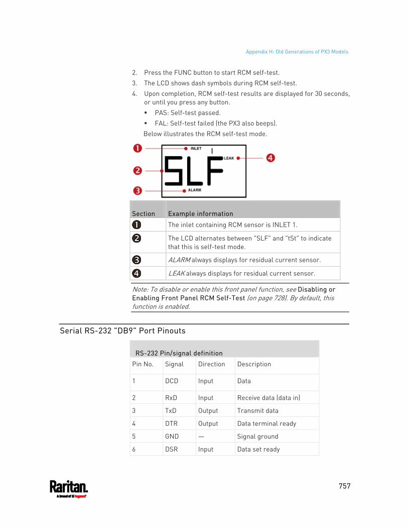
Appendix H: Old Generations of PX3 Models
757
2. Press the FUNC button to start RCM self-test. 3. The LCD shows dash symbols during RCM self-test. 4. Upon completion, RCM self-test results are displayed for 30 seconds,
or until you press any button. PAS: Self-test passed. FAL: Self-test failed (the PX3 also beeps). Below illustrates the RCM self-test mode.
Section Example information
The inlet containing RCM sensor is INLET 1.
The LCD alternates between "SLF" and "tSt" to indicate that this is self-test mode.
ALARM always displays for residual current sensor.
LEAK always displays for residual current sensor.
Note: To disable or enable this front panel function, see Disabling or Enabling Front Panel RCM Self-Test (on page 728). By default, this function is enabled.
Serial RS-232 "DB9" Port Pinouts
RS-232 Pin/signal definition
Pin No. Signal Direction Description
1 DCD Input Data
2 RxD Input Receive data (data in)
3 TxD Output Transmit data
4 DTR Output Data terminal ready
5 GND ― Signal ground
6 DSR Input Data set ready

Appendix H: Old Generations of PX3 Models
758
RS-232 Pin/signal definition
7 RTS Output Request to send
8 CTS Input Clear to send
9 RI Input Ring indicator
759
This section provides an LDAP example for illustrating the configuration procedure using Microsoft Active Directory® (AD). To configure LDAP authentication, four main steps are required:
a. Determine user accounts and roles (groups) intended for the PX3 b. Create user groups for the PX3 on the AD server c. Configure LDAP authentication on the PX3 d. Configure roles on the PX3
Important: Raritan disables SSL 3.0 and uses TLS due to published security vulnerabilities in SSL 3.0. Make sure your network infrastructure, such as LDAP and mail services, uses TLS rather than SSL 3.0.
In This Chapter
Step A. Determine User Accounts and Roles ......................................... 759 Step B. Configure User Groups on the AD Server .................................. 760 Step C. Configure LDAP Authentication on the PX3 ............................... 760 Step D. Configure Roles on the PX3........................................................762
Step A. Determine User Accounts and Roles
Determine the user accounts and roles (groups) that are authenticated for accessing the PX3. In this example, we will create two user roles with different permissions. Each role (group) will consist of two user accounts available on the AD server.
User roles User accounts (members)
usera PX_User
pxuser2
userb PX_Admin
pxuser
Group permissions: The PX_User role will have neither system permissions nor outlet
permissions. The PX_Admin role will have full system and outlet permissions.
Appendix I LDAP Configuration Illustration
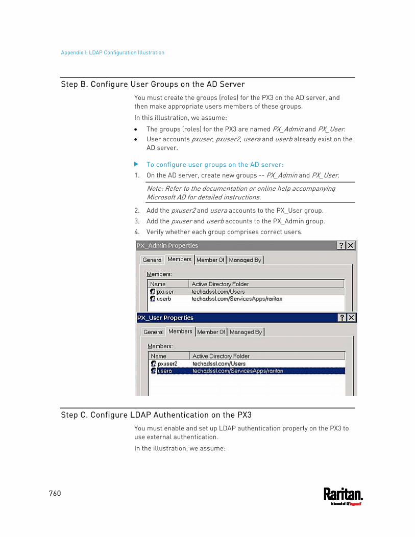
Appendix I: LDAP Configuration Illustration
760
Step B. Configure User Groups on the AD Server
You must create the groups (roles) for the PX3 on the AD server, and then make appropriate users members of these groups.
In this illustration, we assume:
The groups (roles) for the PX3 are named PX_Admin and PX_User. User accounts pxuser, pxuser2, usera and userb already exist on the
AD server.
To configure user groups on the AD server: 1. On the AD server, create new groups -- PX_Admin and PX_User.
Note: Refer to the documentation or online help accompanying Microsoft AD for detailed instructions.
2. Add the pxuser2 and usera accounts to the PX_User group. 3. Add the pxuser and userb accounts to the PX_Admin group. 4. Verify whether each group comprises correct users.
Step C. Configure LDAP Authentication on the PX3
You must enable and set up LDAP authentication properly on the PX3 to use external authentication.
In the illustration, we assume:
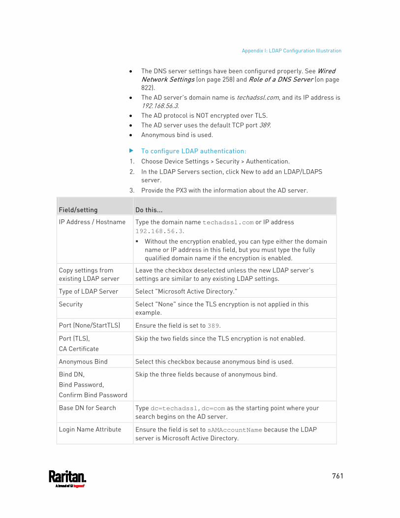
Appendix I: LDAP Configuration Illustration
761
The DNS server settings have been configured properly. See Wired Network Settings (on page 258) and Role of a DNS Server (on page 822).
The AD server's domain name is techadssl.com, and its IP address is 192.168.56.3.
The AD protocol is NOT encrypted over TLS. The AD server uses the default TCP port 389. Anonymous bind is used.
To configure LDAP authentication: 1. Choose Device Settings > Security > Authentication. 2. In the LDAP Servers section, click New to add an LDAP/LDAPS
server. 3. Provide the PX3 with the information about the AD server.
Field/setting Do this...
IP Address / Hostname Type the domain name techadssl.com or IP address 192.168.56.3.
Without the encryption enabled, you can type either the domain name or IP address in this field, but you must type the fully qualified domain name if the encryption is enabled.
Copy settings from existing LDAP server
Leave the checkbox deselected unless the new LDAP server's settings are similar to any existing LDAP settings.
Type of LDAP Server Select "Microsoft Active Directory."
Security Select "None" since the TLS encryption is not applied in this example.
Port (None/StartTLS) Ensure the field is set to 389.
Port (TLS), CA Certificate
Skip the two fields since the TLS encryption is not enabled.
Anonymous Bind Select this checkbox because anonymous bind is used.
Bind DN, Bind Password, Confirm Bind Password
Skip the three fields because of anonymous bind.
Base DN for Search Type dc=techadssl,dc=com as the starting point where your search begins on the AD server.
Login Name Attribute Ensure the field is set to sAMAccountName because the LDAP server is Microsoft Active Directory.
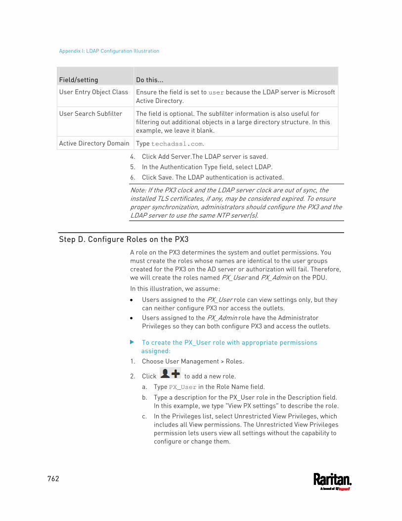
Appendix I: LDAP Configuration Illustration
762
Field/setting Do this...
User Entry Object Class Ensure the field is set to user because the LDAP server is Microsoft Active Directory.
User Search Subfilter The field is optional. The subfilter information is also useful for filtering out additional objects in a large directory structure. In this example, we leave it blank.
Active Directory Domain Type techadssl.com.
4. Click Add Server.The LDAP server is saved. 5. In the Authentication Type field, select LDAP. 6. Click Save. The LDAP authentication is activated.
Note: If the PX3 clock and the LDAP server clock are out of sync, the installed TLS certificates, if any, may be considered expired. To ensure proper synchronization, administrators should configure the PX3 and the LDAP server to use the same NTP server(s).
Step D. Configure Roles on the PX3
A role on the PX3 determines the system and outlet permissions. You must create the roles whose names are identical to the user groups created for the PX3 on the AD server or authorization will fail. Therefore, we will create the roles named PX_User and PX_Admin on the PDU.
In this illustration, we assume:
Users assigned to the PX_User role can view settings only, but they can neither configure PX3 nor access the outlets.
Users assigned to the PX_Admin role have the Administrator Privileges so they can both configure PX3 and access the outlets.
To create the PX_User role with appropriate permissions assigned:
1. Choose User Management > Roles.
2. Click to add a new role.
a. Type PX_User in the Role Name field.
b. Type a description for the PX_User role in the Description field. In this example, we type "View PX settings" to describe the role.
c. In the Privileges list, select Unrestricted View Privileges, which includes all View permissions. The Unrestricted View Privileges permission lets users view all settings without the capability to configure or change them.
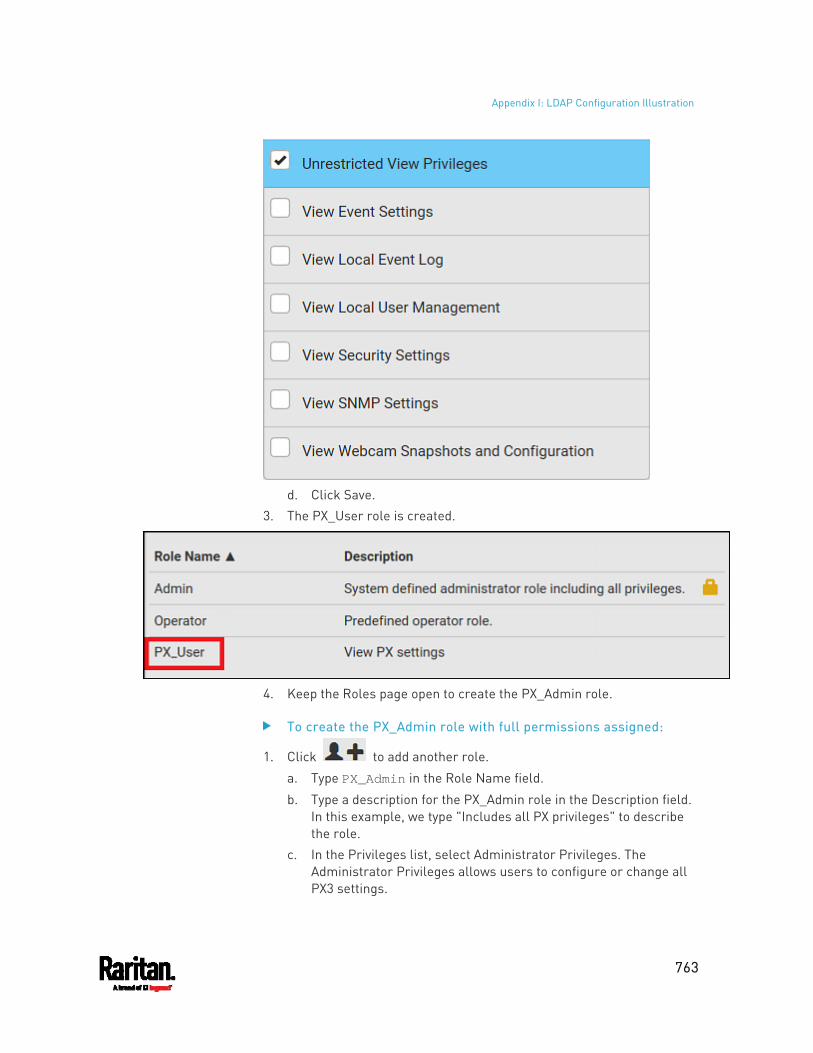
Appendix I: LDAP Configuration Illustration
763
d. Click Save.
3. The PX_User role is created.
4. Keep the Roles page open to create the PX_Admin role.
To create the PX_Admin role with full permissions assigned:
1. Click to add another role.
a. Type PX_Admin in the Role Name field.
b. Type a description for the PX_Admin role in the Description field. In this example, we type "Includes all PX privileges" to describe the role.
c. In the Privileges list, select Administrator Privileges. The Administrator Privileges allows users to configure or change all PX3 settings.
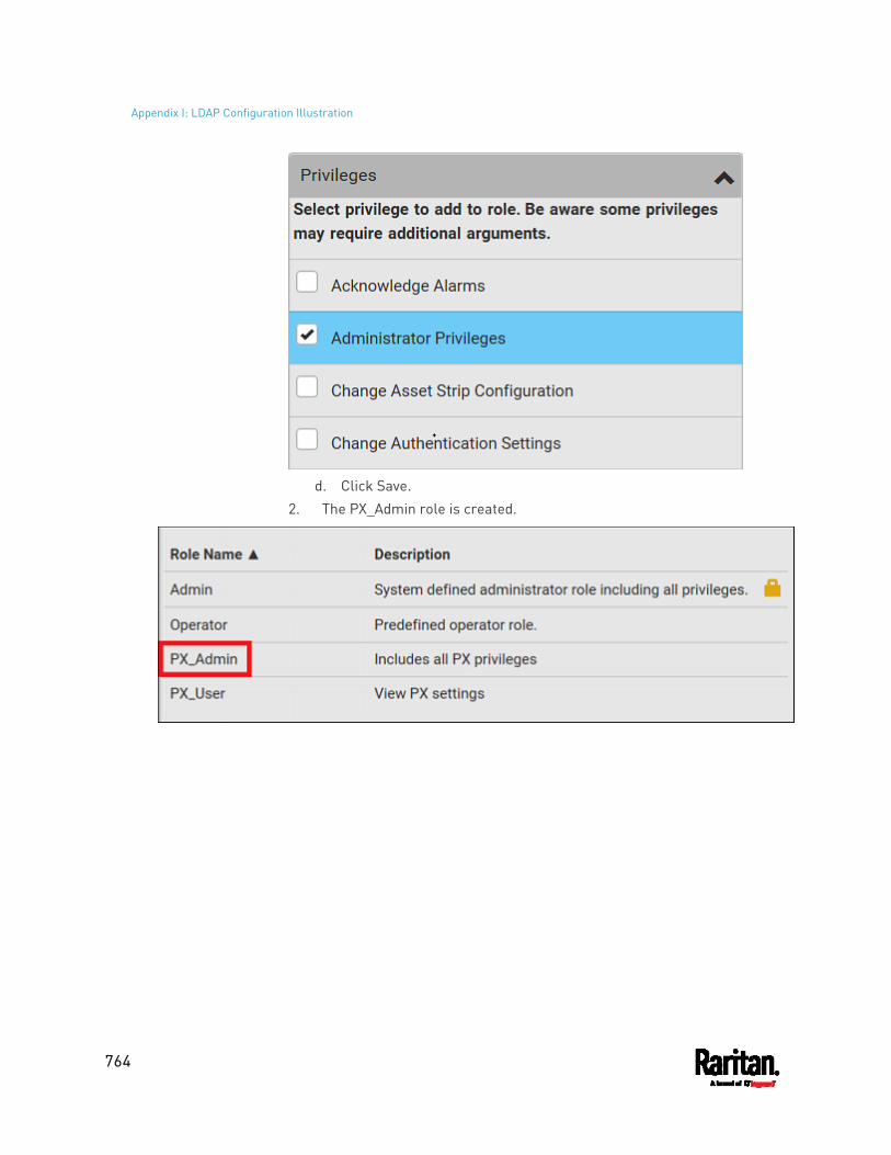
Appendix I: LDAP Configuration Illustration
764
d. Click Save.
2. The PX_Admin role is created.
765
In This Chapter
Returning User Group Information......................................................... 765 Setting the Registry to Permit Write Operations to the Schema ........... 766 Creating a New Attribute......................................................................... 766 Adding Attributes to the Class ................................................................767 Updating the Schema Cache ................................................................... 769 Editing rciusergroup Attributes for User Members ............................... 769
Returning User Group Information
Use the information in this section to return User Group information (and assist with authorization) once authentication is successful.
From LDAP/LDAPS
When an LDAP/LDAPS authentication is successful, the PX3 determines the permissions for a given user based on the permissions of the user's role. Your remote LDAP server can provide these user role names by returning an attribute named as follows:
rciusergroup attribute type: string
This may require a schema extension on your LDAP/LDAPS server. Consult your authentication server administrator to enable this attribute.
In addition, for Microsoft® Active Directory®, the standard LDAP memberOf is used.
From Microsoft Active Directory
Note: This should be attempted only by an experienced Active Directory® administrator.
Returning user role information from Microsoft's® Active Directory for Windows 2000® operating system server requires updating the LDAP/LDAPS schema. See your Microsoft documentation for details.
1. Install the schema plug-in for Active Directory. See Microsoft Active Directory documentation for instructions.
2. Run Active Directory Console and select Active Directory Schema.
Appendix J Updating the LDAP Schema
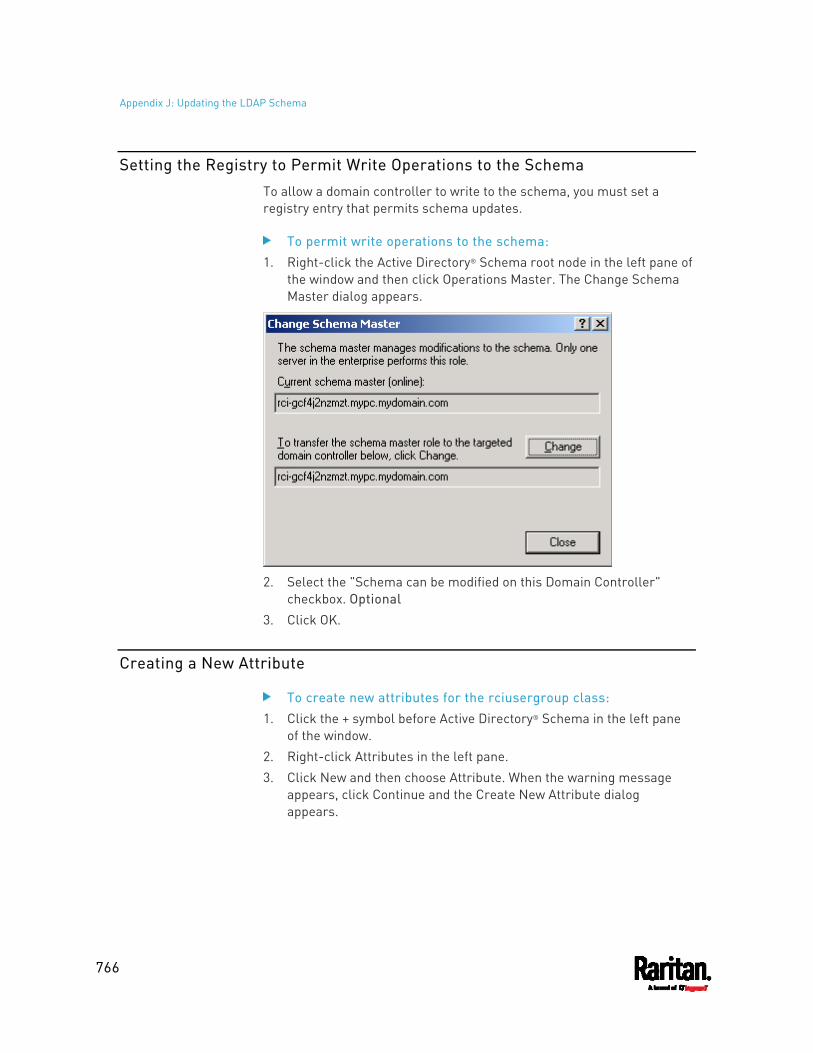
Appendix J: Updating the LDAP Schema
766
Setting the Registry to Permit Write Operations to the Schema
To allow a domain controller to write to the schema, you must set a registry entry that permits schema updates.
To permit write operations to the schema: 1. Right-click the Active Directory® Schema root node in the left pane of
the window and then click Operations Master. The Change Schema Master dialog appears.
2. Select the "Schema can be modified on this Domain Controller"
checkbox. Optional 3. Click OK.
Creating a New Attribute
To create new attributes for the rciusergroup class: 1. Click the + symbol before Active Directory® Schema in the left pane
of the window. 2. Right-click Attributes in the left pane. 3. Click New and then choose Attribute. When the warning message
appears, click Continue and the Create New Attribute dialog appears.
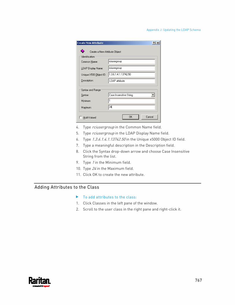
Appendix J: Updating the LDAP Schema
767
4. Type rciusergroup in the Common Name field. 5. Type rciusergroup in the LDAP Display Name field. 6. Type 1.3.6.1.4.1.13742.50 in the Unique x5000 Object ID field. 7. Type a meaningful description in the Description field. 8. Click the Syntax drop-down arrow and choose Case Insensitive
String from the list. 9. Type 1 in the Minimum field. 10. Type 24 in the Maximum field. 11. Click OK to create the new attribute.
Adding Attributes to the Class
To add attributes to the class: 1. Click Classes in the left pane of the window. 2. Scroll to the user class in the right pane and right-click it.
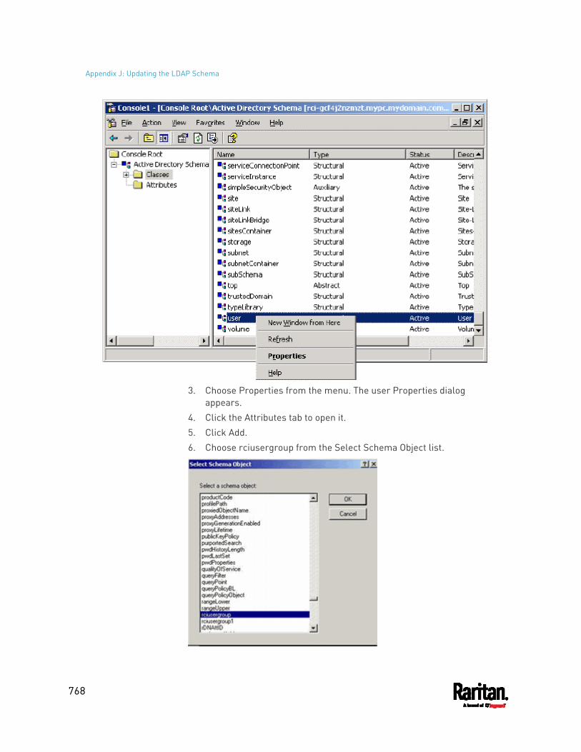
Appendix J: Updating the LDAP Schema
768
3. Choose Properties from the menu. The user Properties dialog
appears. 4. Click the Attributes tab to open it. 5. Click Add. 6. Choose rciusergroup from the Select Schema Object list.
Appendix J: Updating the LDAP Schema
769
7. Click OK in the Select Schema Object dialog. 8. Click OK in the User Properties dialog.
Updating the Schema Cache
To update the schema cache: 1. Right-click Active Directory® Schema in the left pane of the window
and select Reload the Schema. 2. Minimize the Active Directory Schema MMC (Microsoft® Management
Console) console.
Editing rciusergroup Attributes for User Members
To run the Active Directory® script on a Windows 2003® server, use the script provided by Microsoft® (available on the Windows 2003 server installation CD). These scripts are loaded onto your system with a Microsoft® Windows 2003 installation. ADSI (Active Directory Service Interface) acts as a low-level editor for Active Directory, allowing you to perform common administrative tasks such as adding, deleting, and moving objects with a directory service.
To edit the individual user attributes within the group rciusergroup:
1. From the installation CD, choose Support > Tools. 2. Double-click SUPTOOLS.MSI to install the support tools. 3. Go to the directory where the support tools were installed. Run
adsiedit.msc. The ADSI Edit window opens.
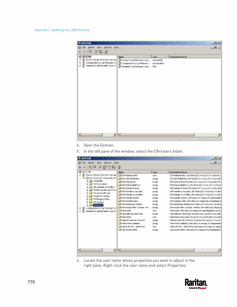
Appendix J: Updating the LDAP Schema
770
4. Open the Domain. 5. In the left pane of the window, select the CN=Users folder.
6. Locate the user name whose properties you want to adjust in the
right pane. Right-click the user name and select Properties.
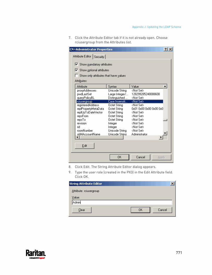
Appendix J: Updating the LDAP Schema
771
7. Click the Attribute Editor tab if it is not already open. Choose rciusergroup from the Attributes list.
8. Click Edit. The String Attribute Editor dialog appears. 9. Type the user role (created in the PX3) in the Edit Attribute field.
Click OK.
772
This section provides illustrations for configuring RADIUS authentication. One illustration is based on the Microsoft® Network Policy Server (NPS), and the other is based on a FreeRADIUS server.
The following steps are required for any RADIUS authentication:
1. Configure RADIUS authentication on the PX3. See Adding Radius Servers (on page 304).
2. Configure roles on the PX3. See Creating Roles (on page 250). 3. Configure PX3 user credentials and roles on your RADIUS server.
To configure using standard attributes, see Standard Attributes (on page 772).
To configure using vendor-specific attributes, see Vendor-Specific Attributes (on page 790).
Note that we assume that the NPS is running on a Windows 2008 system in the NPS illustrations.
In This Chapter
Standard Attributes ................................................................................. 772 Vendor-Specific Attributes ...................................................................... 790 AD-Related Configuration ....................................................................... 802
Standard Attributes
The RADIUS standard attribute "Filter-ID" is used to convey the group membership, that is, roles.
If a user has multiple roles, configure multiple standard attributes for this user.
The syntax of a standard attribute is: Raritan:G{role-name}
For configuration on NPS, see NPS Standard Attribute Illustration (on page 772).
For configuration on FreeRADIUS, see FreeRADIUS Standard Attribute Illustration (on page 789).
NPS Standard Attribute Illustration
To configure Windows 2008 NPS with the standard attribute, you must:
a. Add your PX3 to NPS. See Step A: Add Your PX3 as a RADIUS Client (on page 773).
Appendix K RADIUS Configuration Illustration
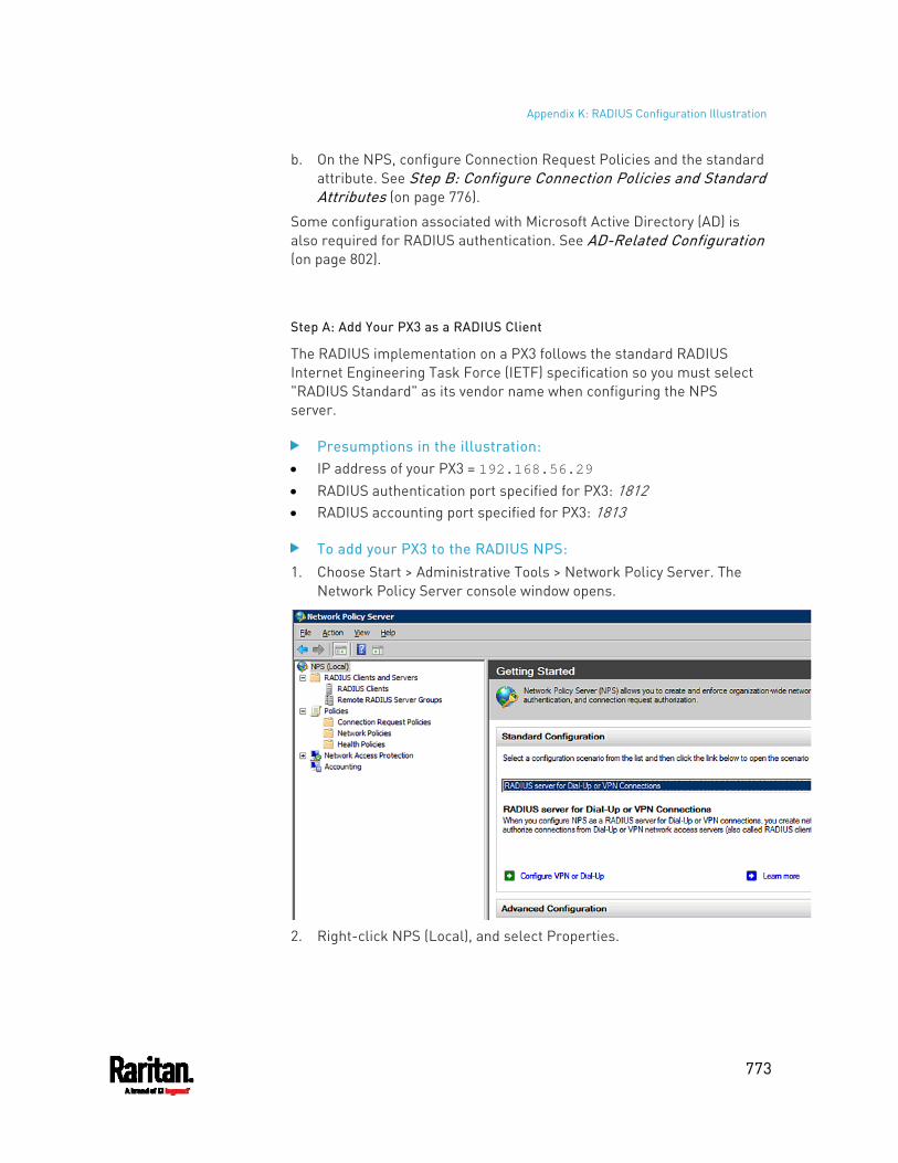
Appendix K: RADIUS Configuration Illustration
773
b. On the NPS, configure Connection Request Policies and the standard attribute. See Step B: Configure Connection Policies and Standard Attributes (on page 776).
Some configuration associated with Microsoft Active Directory (AD) is also required for RADIUS authentication. See AD-Related Configuration (on page 802).
Step A: Add Your PX3 as a RADIUS Client
The RADIUS implementation on a PX3 follows the standard RADIUS Internet Engineering Task Force (IETF) specification so you must select "RADIUS Standard" as its vendor name when configuring the NPS server.
Presumptions in the illustration: IP address of your PX3 = 192.168.56.29 RADIUS authentication port specified for PX3: 1812 RADIUS accounting port specified for PX3: 1813
To add your PX3 to the RADIUS NPS: 1. Choose Start > Administrative Tools > Network Policy Server. The
Network Policy Server console window opens.
2. Right-click NPS (Local), and select Properties.
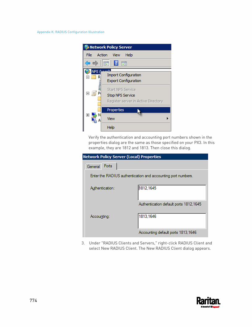
Appendix K: RADIUS Configuration Illustration
774
Verify the authentication and accounting port numbers shown in the properties dialog are the same as those specified on your PX3. In this example, they are 1812 and 1813. Then close this dialog.
3. Under "RADIUS Clients and Servers," right-click RADIUS Client and
select New RADIUS Client. The New RADIUS Client dialog appears.
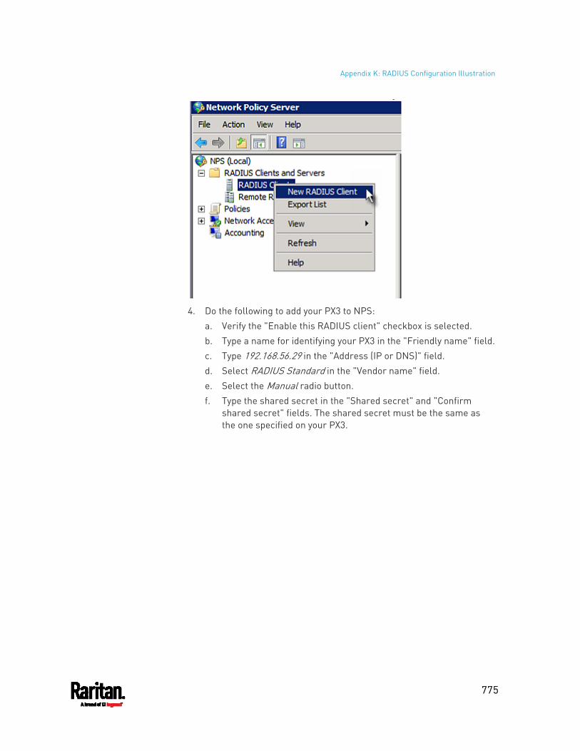
Appendix K: RADIUS Configuration Illustration
775
4. Do the following to add your PX3 to NPS:
a. Verify the "Enable this RADIUS client" checkbox is selected. b. Type a name for identifying your PX3 in the "Friendly name" field. c. Type 192.168.56.29 in the "Address (IP or DNS)" field. d. Select RADIUS Standard in the "Vendor name" field. e. Select the Manual radio button. f. Type the shared secret in the "Shared secret" and "Confirm
shared secret" fields. The shared secret must be the same as the one specified on your PX3.
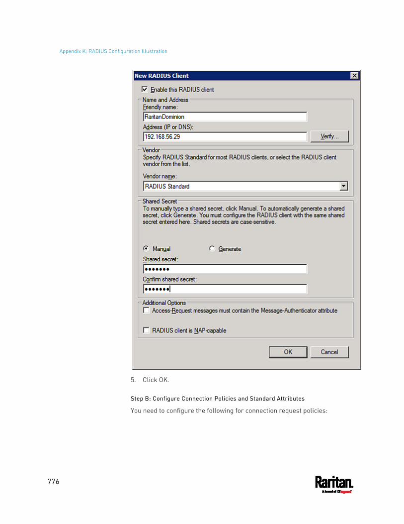
Appendix K: RADIUS Configuration Illustration
776
5. Click OK.
Step B: Configure Connection Policies and Standard Attributes
You need to configure the following for connection request policies:
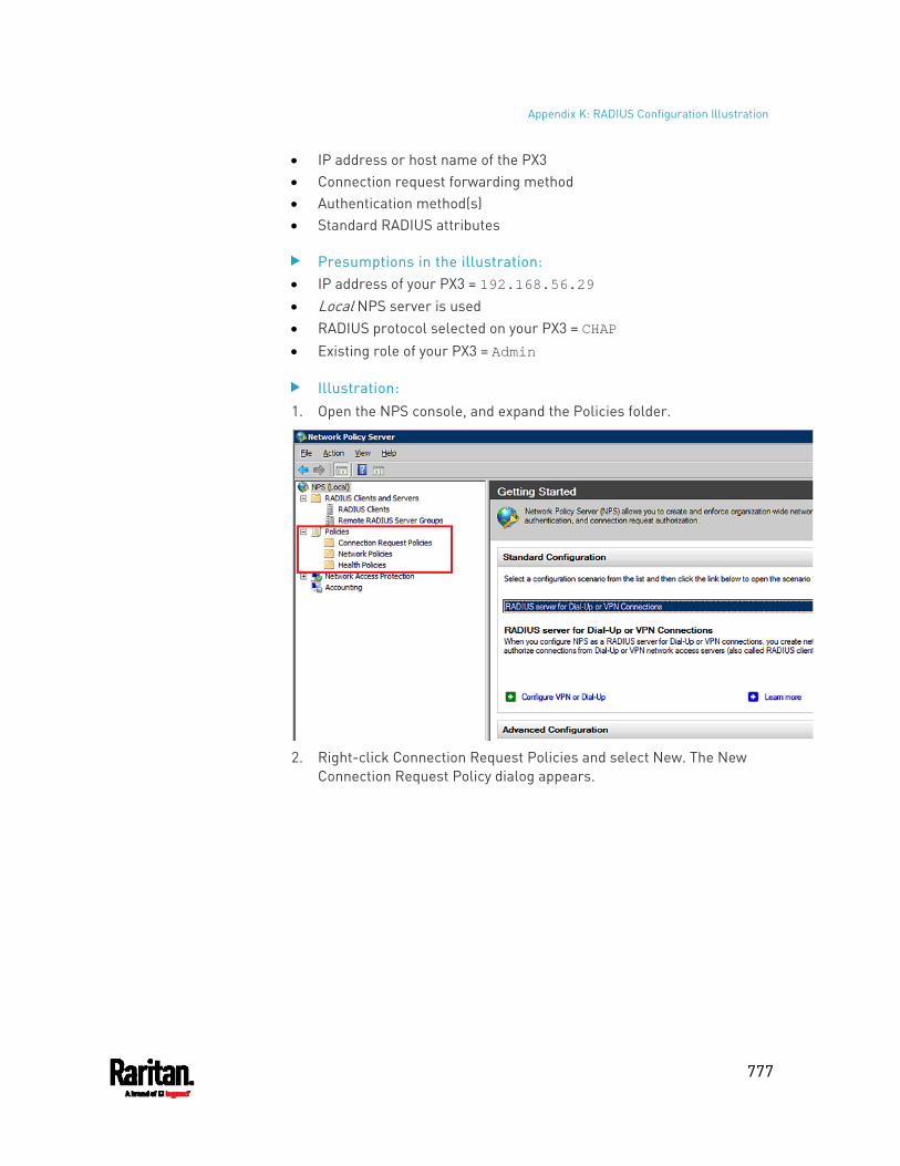
Appendix K: RADIUS Configuration Illustration
777
IP address or host name of the PX3 Connection request forwarding method Authentication method(s) Standard RADIUS attributes
Presumptions in the illustration: IP address of your PX3 = 192.168.56.29 Local NPS server is used RADIUS protocol selected on your PX3 = CHAP Existing role of your PX3 = Admin
Illustration: 1. Open the NPS console, and expand the Policies folder.
2. Right-click Connection Request Policies and select New. The New
Connection Request Policy dialog appears.
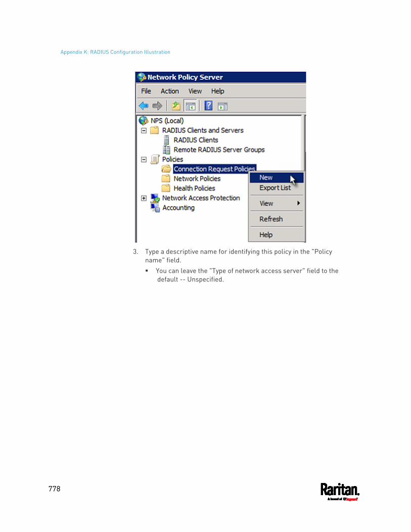
Appendix K: RADIUS Configuration Illustration
778
3. Type a descriptive name for identifying this policy in the "Policy
name" field. You can leave the "Type of network access server" field to the
default -- Unspecified.
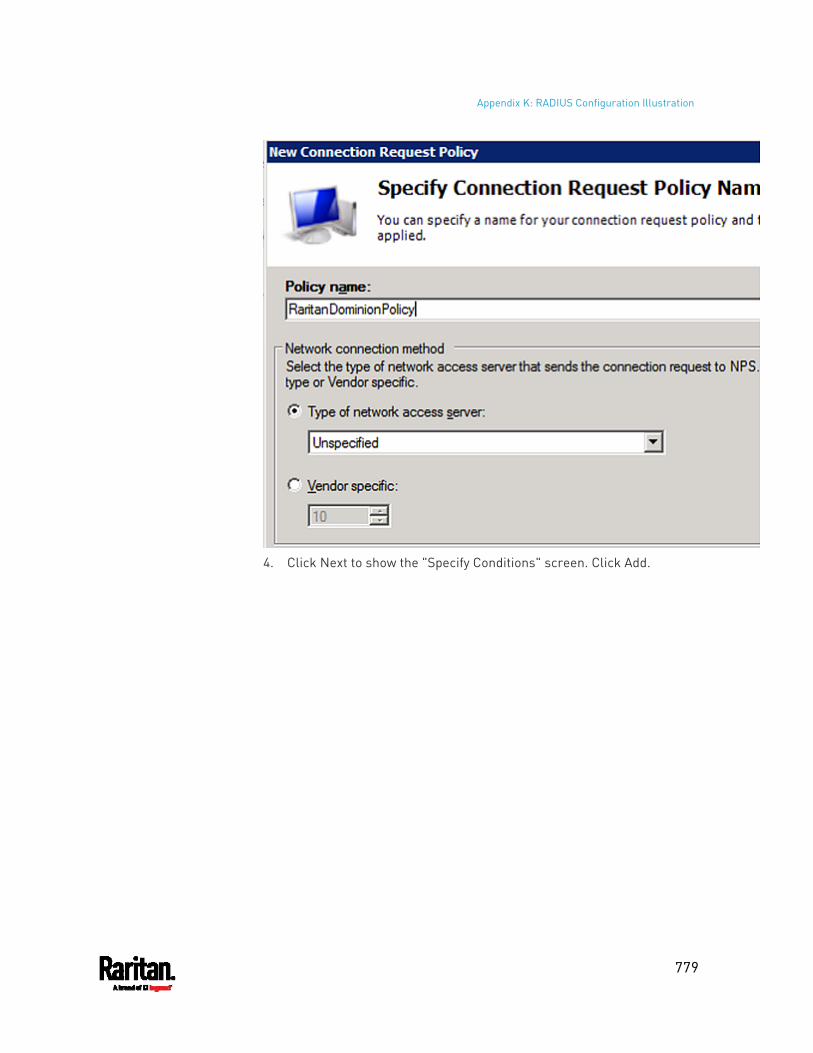
Appendix K: RADIUS Configuration Illustration
779
4. Click Next to show the "Specify Conditions" screen. Click Add.
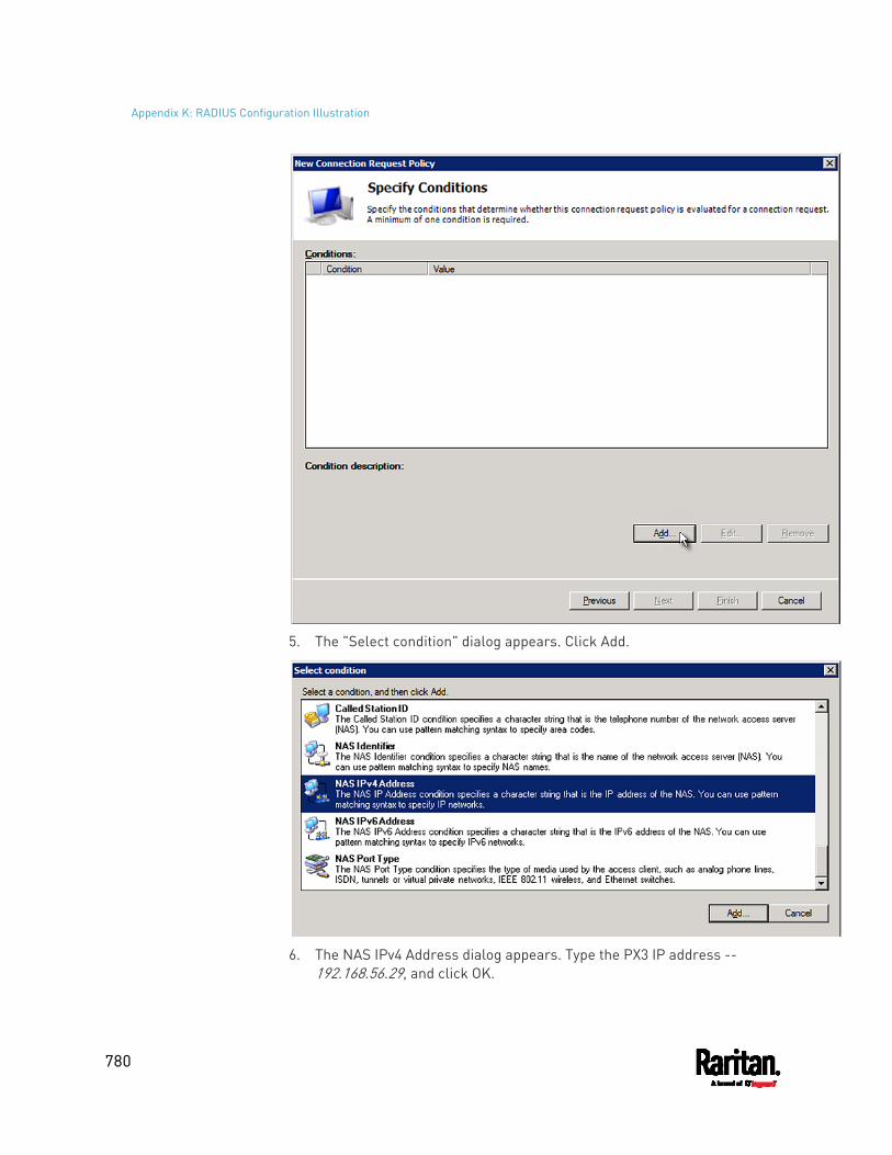
Appendix K: RADIUS Configuration Illustration
780
5. The "Select condition" dialog appears. Click Add.
6. The NAS IPv4 Address dialog appears. Type the PX3 IP address --
192.168.56.29, and click OK.
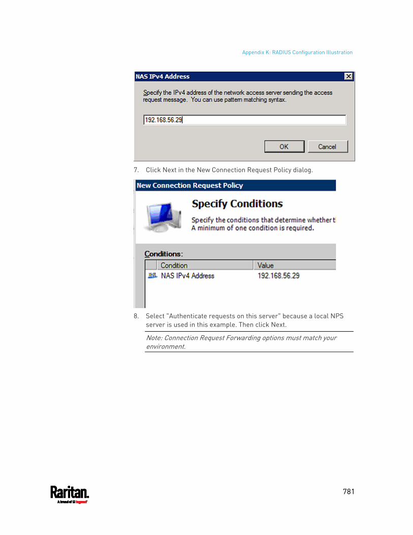
Appendix K: RADIUS Configuration Illustration
781
7. Click Next in the New Connection Request Policy dialog.
8. Select "Authenticate requests on this server" because a local NPS
server is used in this example. Then click Next.
Note: Connection Request Forwarding options must match your environment.
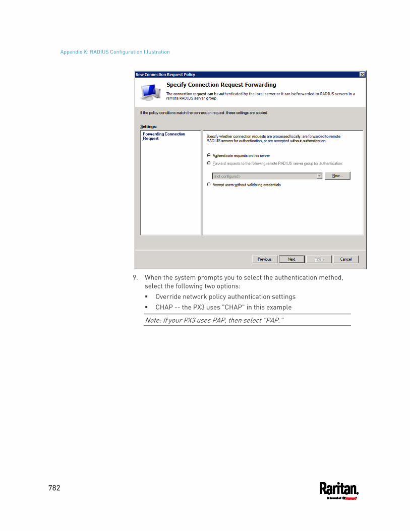
Appendix K: RADIUS Configuration Illustration
782
9. When the system prompts you to select the authentication method,
select the following two options: Override network policy authentication settings CHAP -- the PX3 uses "CHAP" in this example
Note: If your PX3 uses PAP, then select "PAP."
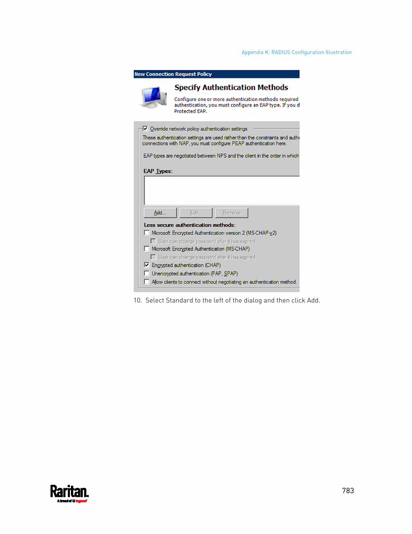
Appendix K: RADIUS Configuration Illustration
783
10. Select Standard to the left of the dialog and then click Add.
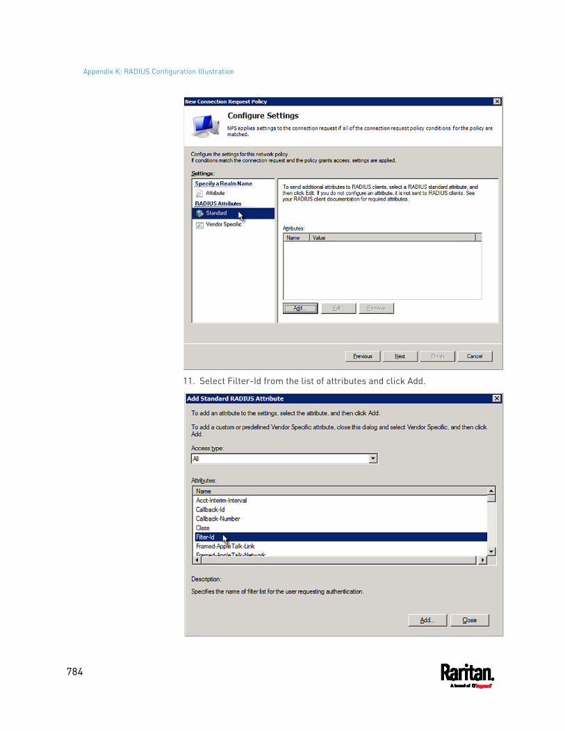
Appendix K: RADIUS Configuration Illustration
784
11. Select Filter-Id from the list of attributes and click Add.
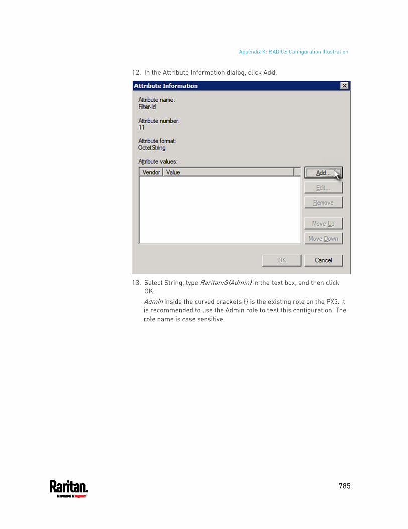
Appendix K: RADIUS Configuration Illustration
785
12. In the Attribute Information dialog, click Add.
13. Select String, type Raritan:G{Admin} in the text box, and then click
OK. Admin inside the curved brackets {} is the existing role on the PX3. It is recommended to use the Admin role to test this configuration. The role name is case sensitive.
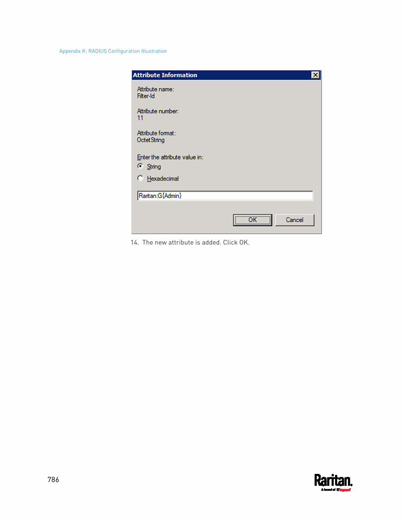
Appendix K: RADIUS Configuration Illustration
786
14. The new attribute is added. Click OK.
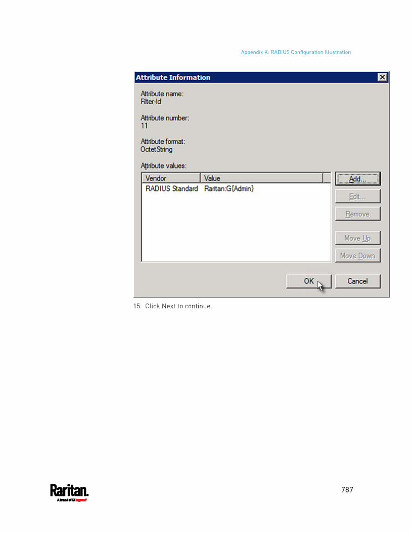
Appendix K: RADIUS Configuration Illustration
787
15. Click Next to continue.
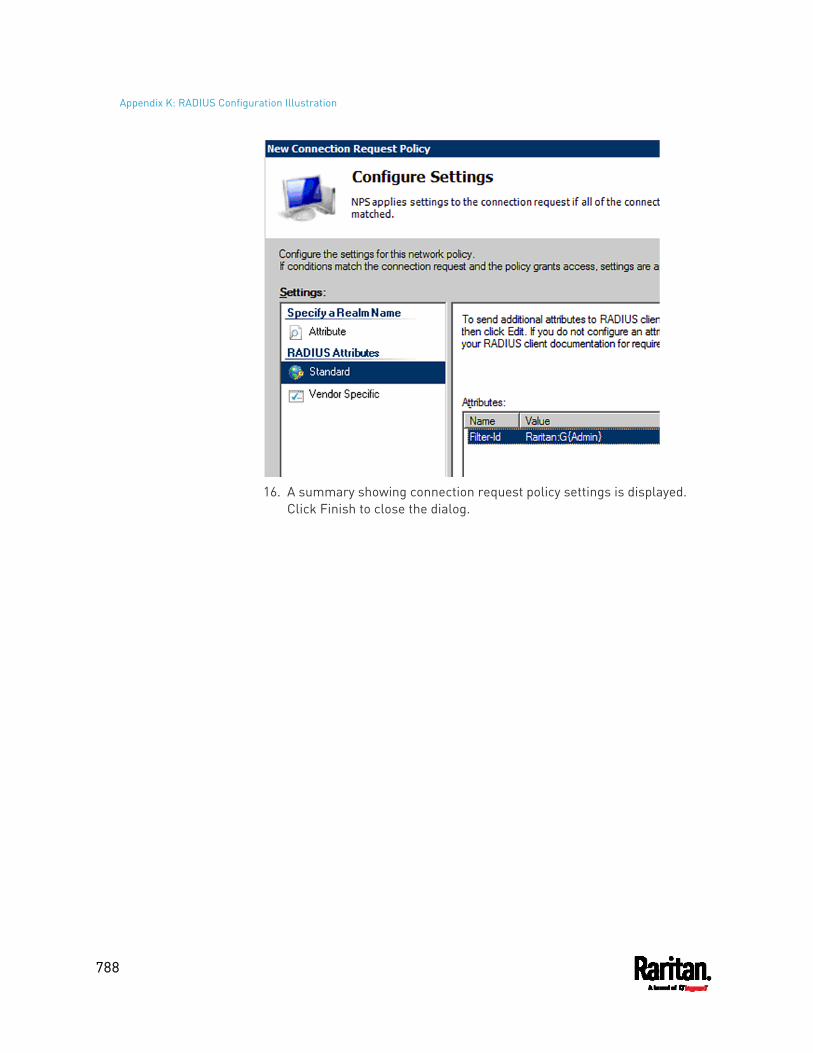
Appendix K: RADIUS Configuration Illustration
788
16. A summary showing connection request policy settings is displayed.
Click Finish to close the dialog.
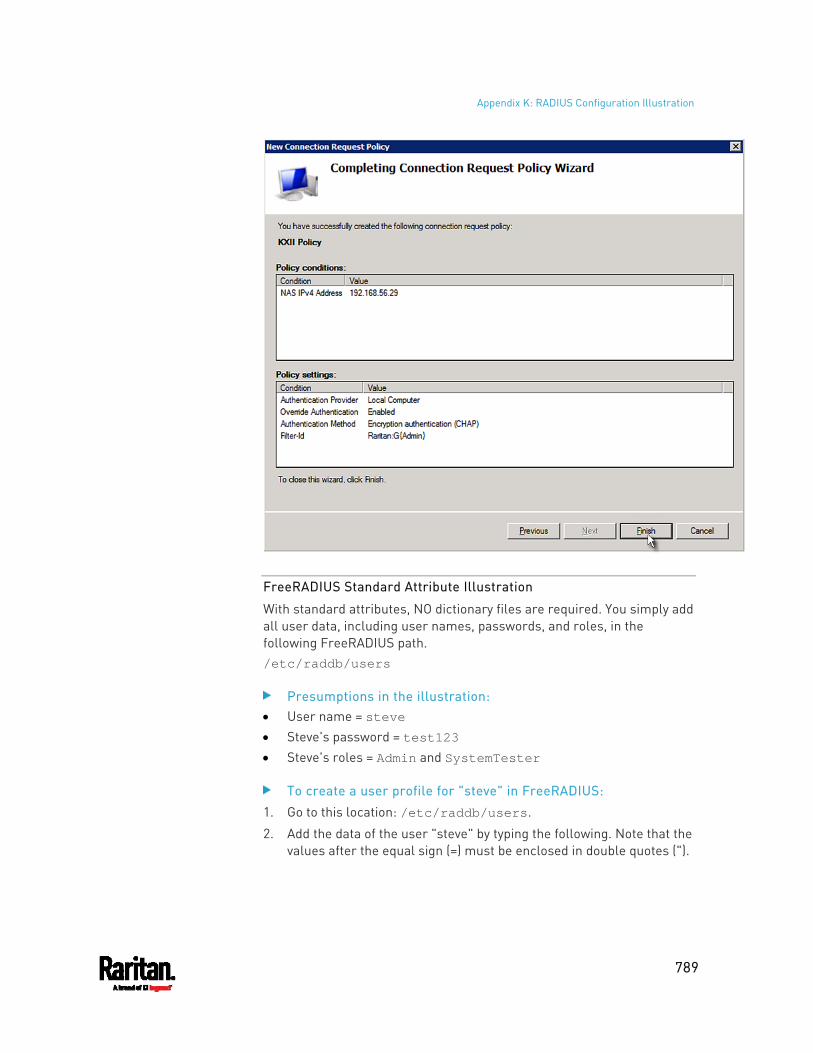
Appendix K: RADIUS Configuration Illustration
789
FreeRADIUS Standard Attribute Illustration
With standard attributes, NO dictionary files are required. You simply add all user data, including user names, passwords, and roles, in the following FreeRADIUS path. /etc/raddb/users
Presumptions in the illustration: User name = steve Steve's password = test123 Steve's roles = Admin and SystemTester
To create a user profile for "steve" in FreeRADIUS:
1. Go to this location: /etc/raddb/users.
2. Add the data of the user "steve" by typing the following. Note that the values after the equal sign (=) must be enclosed in double quotes (").
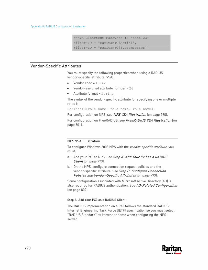
Appendix K: RADIUS Configuration Illustration
790
steve Cleartext-Password := "test123" Filter-ID = "Raritan:G{Admin}", Filter-ID = "Raritan:G{SystemTester}"
Vendor-Specific Attributes
You must specify the following properties when using a RADIUS vendor-specific attribute (VSA).
Vendor code = 13742 Vendor-assigned attribute number = 26 Attribute format = String
The syntax of the vendor-specific attribute for specifying one or multiple roles is: Raritan:G{role-name1 role-name2 role-name3}
For configuration on NPS, see NPS VSA Illustration (on page 790).
For configuration on FreeRADIUS, see FreeRADIUS VSA Illustration (on page 801).
NPS VSA Illustration
To configure Windows 2008 NPS with the vendor-specific attribute, you must:
a. Add your PX3 to NPS. See Step A: Add Your PX3 as a RADIUS Client (on page 773).
b. On the NPS, configure connection request policies and the vendor-specific attribute. See Step B: Configure Connection Policies and Vendor-Specific Attributes (on page 793).
Some configuration associated with Microsoft Active Directory (AD) is also required for RADIUS authentication. See AD-Related Configuration (on page 802).
Step A: Add Your PX3 as a RADIUS Client
The RADIUS implementation on a PX3 follows the standard RADIUS Internet Engineering Task Force (IETF) specification so you must select "RADIUS Standard" as its vendor name when configuring the NPS server.
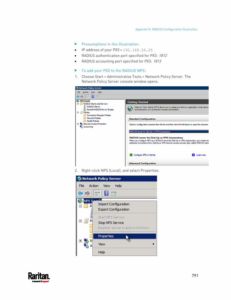
Appendix K: RADIUS Configuration Illustration
791
Presumptions in the illustration: IP address of your PX3 = 192.168.56.29 RADIUS authentication port specified for PX3: 1812 RADIUS accounting port specified for PX3: 1813
To add your PX3 to the RADIUS NPS: 1. Choose Start > Administrative Tools > Network Policy Server. The
Network Policy Server console window opens.
2. Right-click NPS (Local), and select Properties.
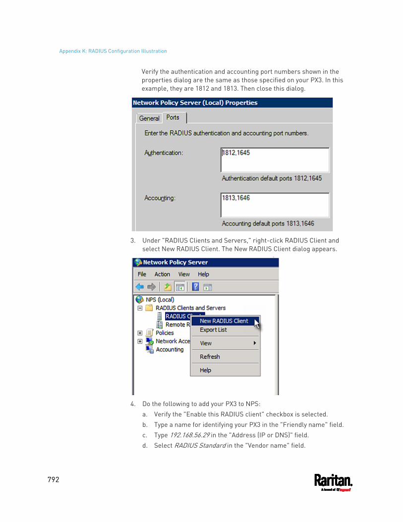
Appendix K: RADIUS Configuration Illustration
792
Verify the authentication and accounting port numbers shown in the properties dialog are the same as those specified on your PX3. In this example, they are 1812 and 1813. Then close this dialog.
3. Under "RADIUS Clients and Servers," right-click RADIUS Client and
select New RADIUS Client. The New RADIUS Client dialog appears.
4. Do the following to add your PX3 to NPS:
a. Verify the "Enable this RADIUS client" checkbox is selected. b. Type a name for identifying your PX3 in the "Friendly name" field. c. Type 192.168.56.29 in the "Address (IP or DNS)" field. d. Select RADIUS Standard in the "Vendor name" field.
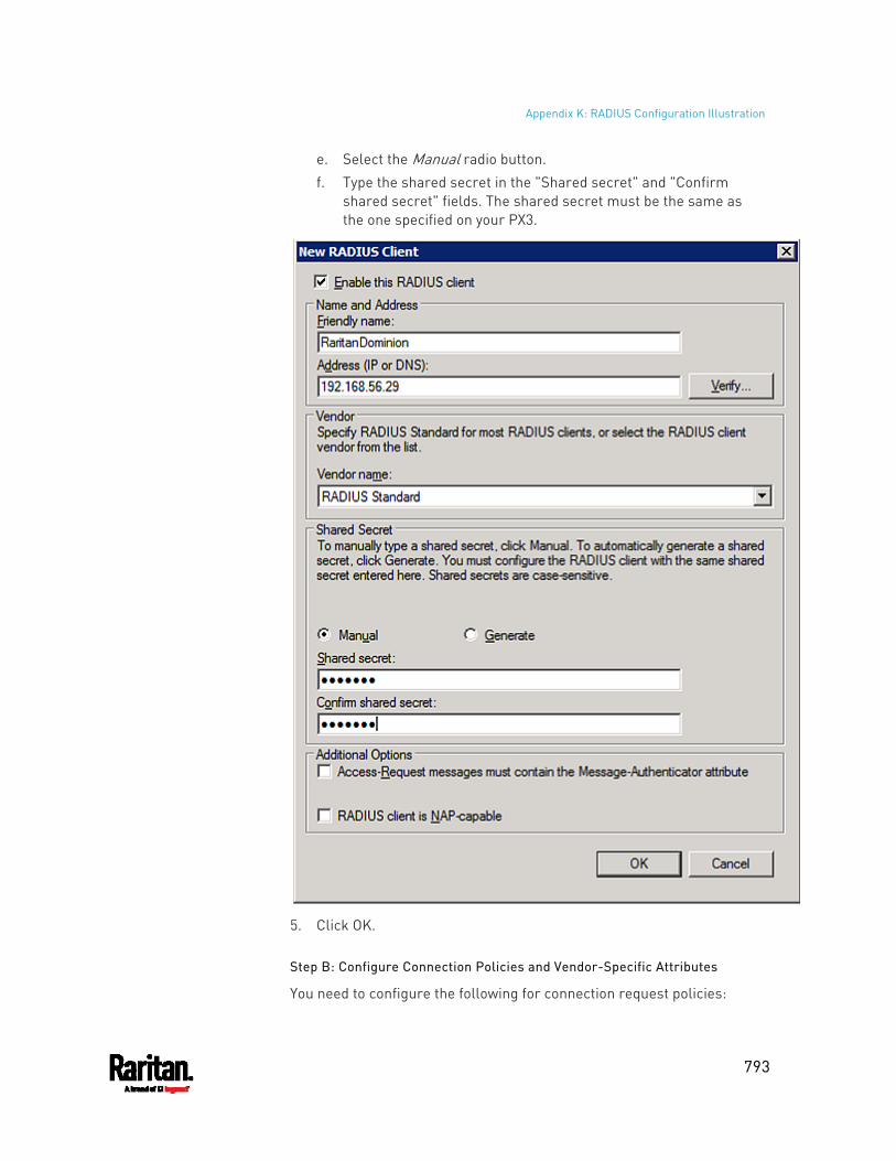
Appendix K: RADIUS Configuration Illustration
793
e. Select the Manual radio button. f. Type the shared secret in the "Shared secret" and "Confirm
shared secret" fields. The shared secret must be the same as the one specified on your PX3.
5. Click OK.
Step B: Configure Connection Policies and Vendor-Specific Attributes
You need to configure the following for connection request policies:
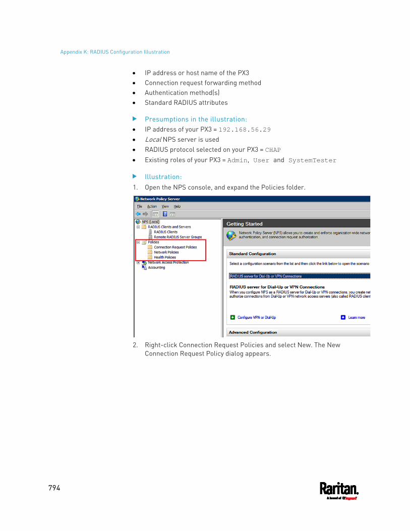
Appendix K: RADIUS Configuration Illustration
794
IP address or host name of the PX3 Connection request forwarding method Authentication method(s) Standard RADIUS attributes
Presumptions in the illustration: IP address of your PX3 = 192.168.56.29 Local NPS server is used RADIUS protocol selected on your PX3 = CHAP Existing roles of your PX3 = Admin, User and SystemTester
Illustration: 1. Open the NPS console, and expand the Policies folder.
2. Right-click Connection Request Policies and select New. The New
Connection Request Policy dialog appears.
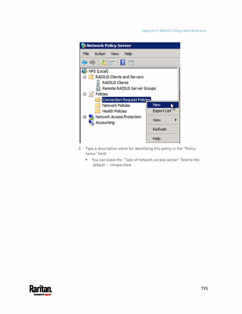
Appendix K: RADIUS Configuration Illustration
795
3. Type a descriptive name for identifying this policy in the "Policy
name" field. You can leave the "Type of network access server" field to the
default -- Unspecified.
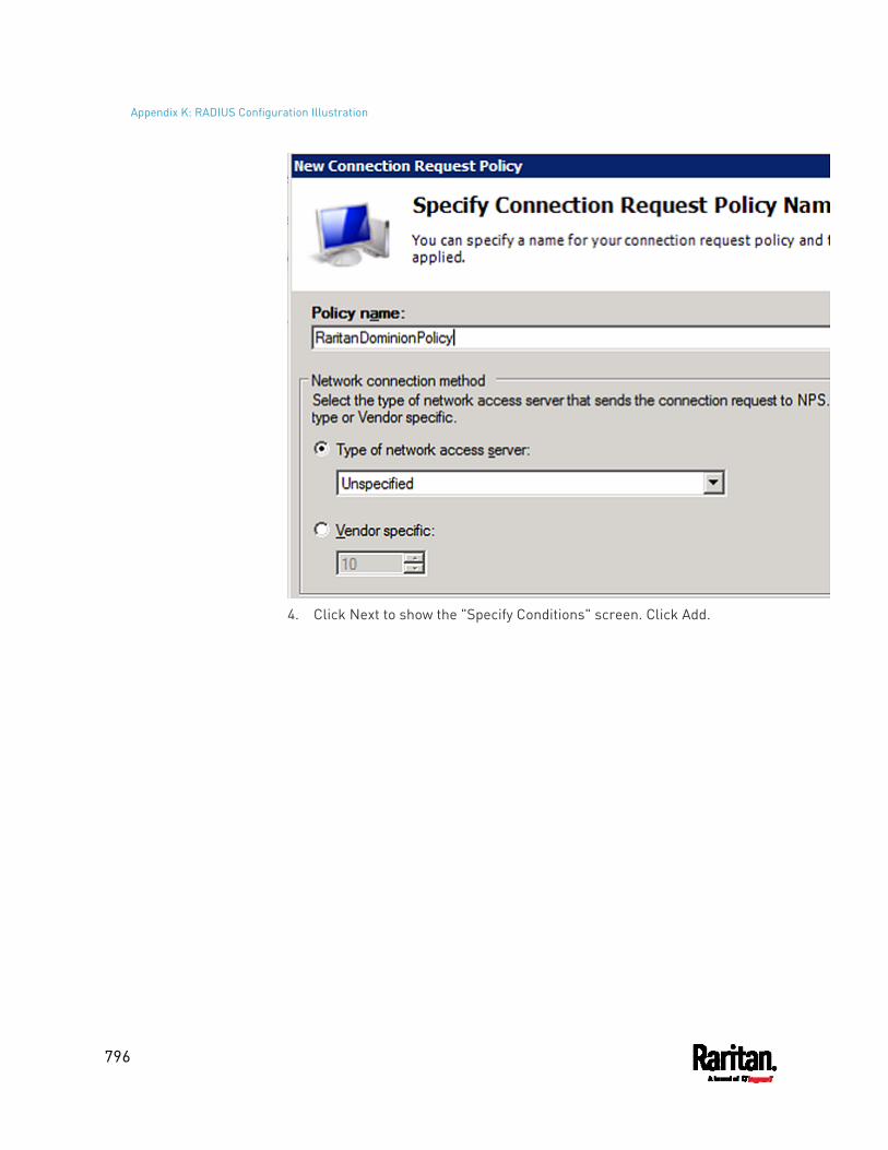
Appendix K: RADIUS Configuration Illustration
796
4. Click Next to show the "Specify Conditions" screen. Click Add.
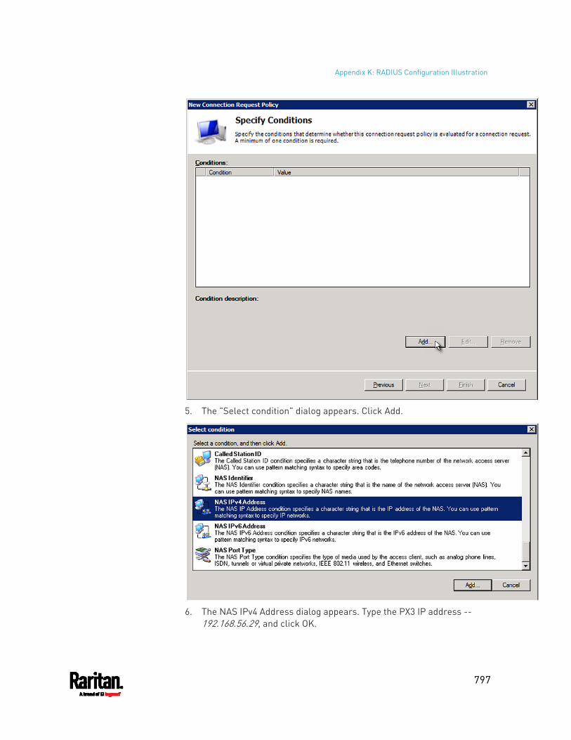
Appendix K: RADIUS Configuration Illustration
797
5. The "Select condition" dialog appears. Click Add.
6. The NAS IPv4 Address dialog appears. Type the PX3 IP address --
192.168.56.29, and click OK.
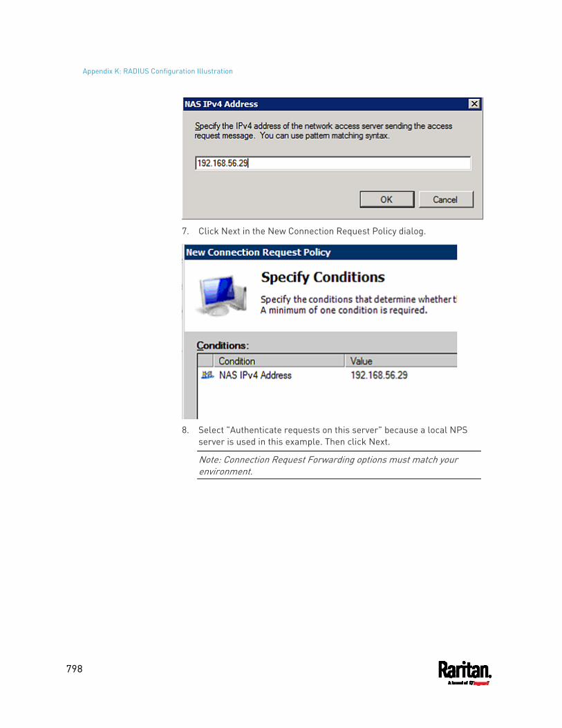
Appendix K: RADIUS Configuration Illustration
798
7. Click Next in the New Connection Request Policy dialog.
8. Select "Authenticate requests on this server" because a local NPS
server is used in this example. Then click Next.
Note: Connection Request Forwarding options must match your environment.
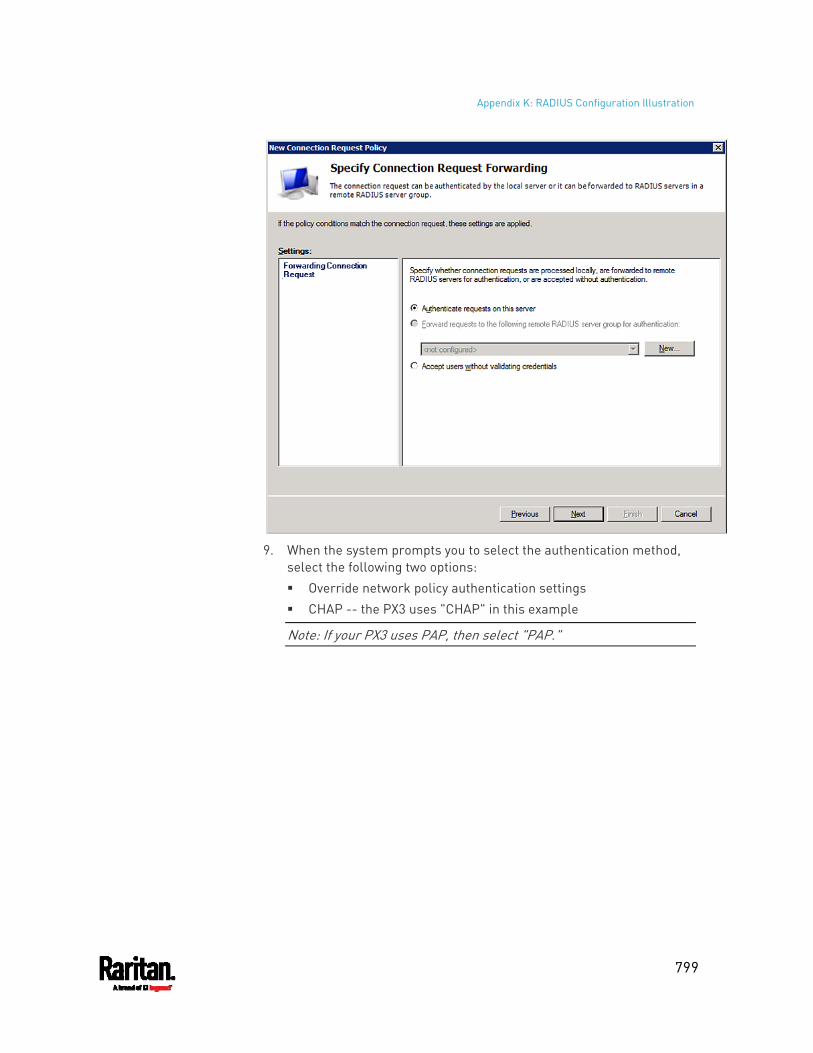
Appendix K: RADIUS Configuration Illustration
799
9. When the system prompts you to select the authentication method,
select the following two options: Override network policy authentication settings CHAP -- the PX3 uses "CHAP" in this example
Note: If your PX3 uses PAP, then select "PAP."
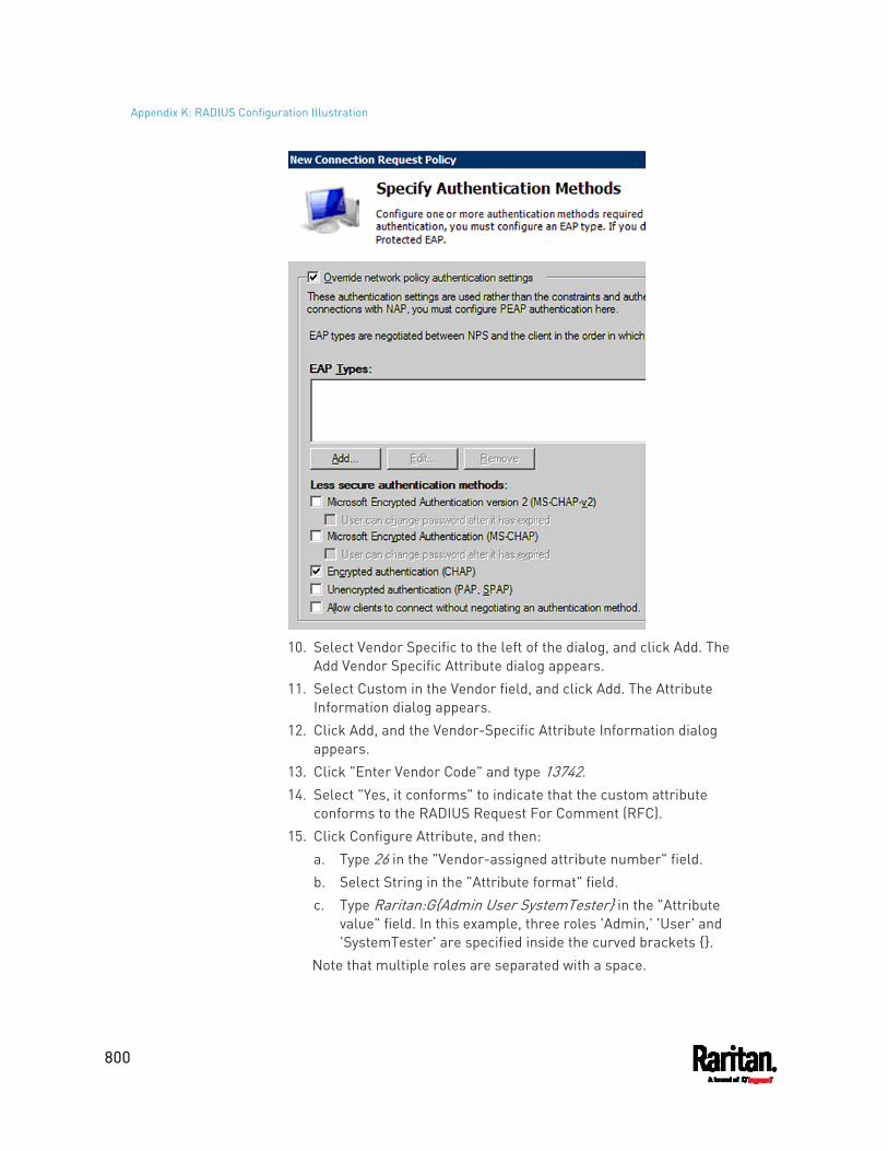
Appendix K: RADIUS Configuration Illustration
800
10. Select Vendor Specific to the left of the dialog, and click Add. The
Add Vendor Specific Attribute dialog appears. 11. Select Custom in the Vendor field, and click Add. The Attribute
Information dialog appears. 12. Click Add, and the Vendor-Specific Attribute Information dialog
appears. 13. Click "Enter Vendor Code" and type 13742. 14. Select "Yes, it conforms" to indicate that the custom attribute
conforms to the RADIUS Request For Comment (RFC). 15. Click Configure Attribute, and then:
a. Type 26 in the "Vendor-assigned attribute number" field. b. Select String in the "Attribute format" field. c. Type Raritan:G{Admin User SystemTester} in the "Attribute
value" field. In this example, three roles 'Admin,' 'User' and 'SystemTester' are specified inside the curved brackets {}.
Note that multiple roles are separated with a space.
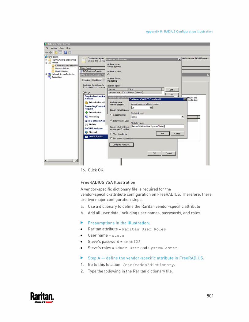
Appendix K: RADIUS Configuration Illustration
801
16. Click OK.
FreeRADIUS VSA Illustration
A vendor-specific dictionary file is required for the vendor-specific-attribute configuration on FreeRADIUS. Therefore, there are two major configuration steps.
a. Use a dictionary to define the Raritan vendor-specific attribute b. Add all user data, including user names, passwords, and roles
Presumptions in the illustration: Raritan attribute = Raritan-User-Roles User name = steve Steve's password = test123 Steve's roles = Admin, User and SystemTester
Step A -- define the vendor-specific attribute in FreeRADIUS:
1. Go to this location: /etc/raddb/dictionary.
2. Type the following in the Raritan dictionary file.
Appendix K: RADIUS Configuration Illustration
802
VENDOR Raritan 13742 BEGIN-VENDOR Raritan ATTRIBUTE Raritan-User-Roles 26 string END-VENDOR Raritan
Step B -- create a user profile for "steve" in FreeRADIUS:
1. Go to this location: /etc/raddb/users.
2. Add the data of the user "steve" by typing the following. Note that the values after the equal sign (=) must be enclosed in double quotes (").
steve Cleartext-Password := "test123" Raritan-PDU-User-Roles = "Raritan:G{Admin User SystemTester}"
AD-Related Configuration
When RADIUS authentication is intended, make sure you also configure the following settings related to Microsoft Active Directory (AD):
Register the NPS server in AD Configure remote access permission for users in AD
The NPS server is registered in AD only when NPS is configured for the FIRST time and user accounts are created in AD.
If CHAP authentication is used, you must enable the following feature for user accounts created in AD:
Store password using reversible encryption
Important: Reset the user password if the password is set before you enable the "Store password using reversible encryption" feature.
To register NPS: 1. Open the NPS console. 2. Right-click NPS (Local) and select "Register server in Active
Directory."
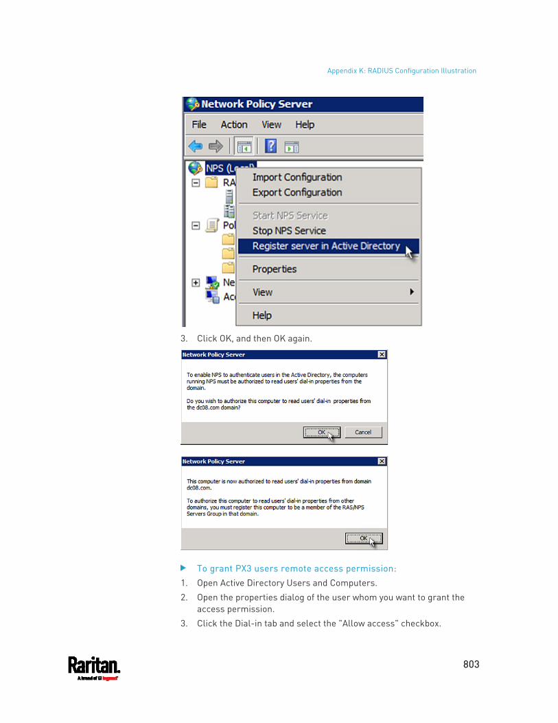
Appendix K: RADIUS Configuration Illustration
803
3. Click OK, and then OK again.
To grant PX3 users remote access permission: 1. Open Active Directory Users and Computers. 2. Open the properties dialog of the user whom you want to grant the
access permission. 3. Click the Dial-in tab and select the "Allow access" checkbox.
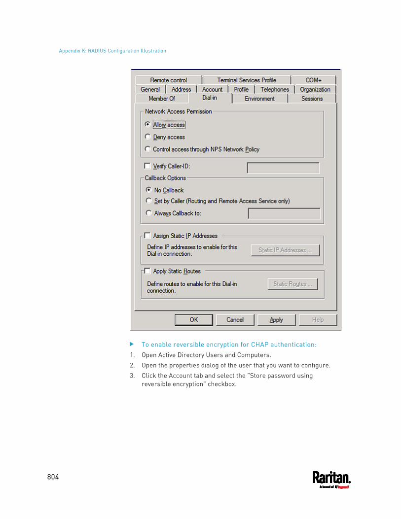
Appendix K: RADIUS Configuration Illustration
804
To enable reversible encryption for CHAP authentication: 1. Open Active Directory Users and Computers. 2. Open the properties dialog of the user that you want to configure. 3. Click the Account tab and select the "Store password using
reversible encryption" checkbox.
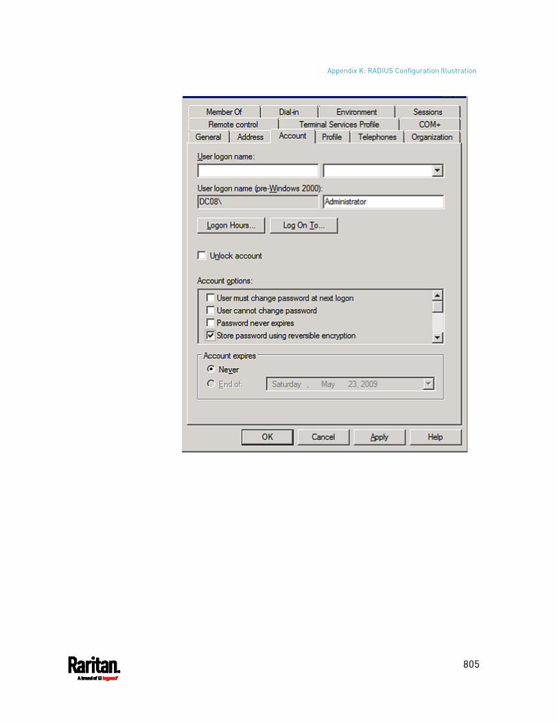
Appendix K: RADIUS Configuration Illustration
805
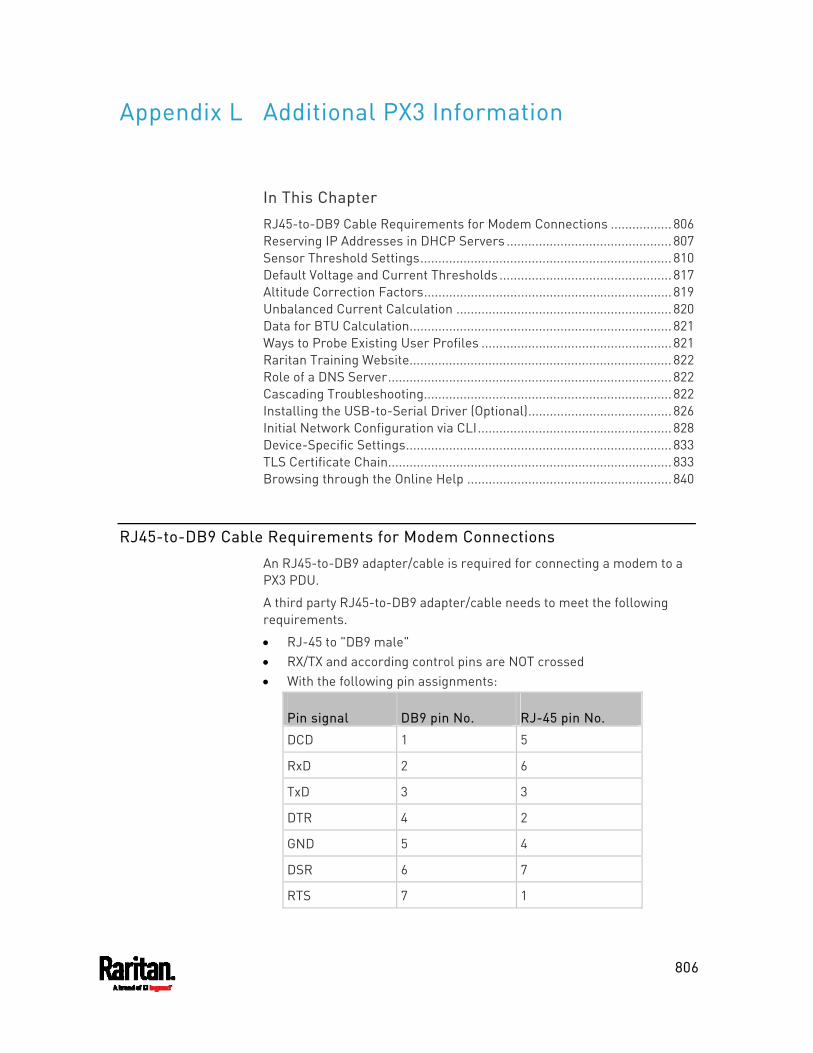
806
In This Chapter
RJ45-to-DB9 Cable Requirements for Modem Connections ................. 806 Reserving IP Addresses in DHCP Servers .............................................. 807 Sensor Threshold Settings...................................................................... 810 Default Voltage and Current Thresholds ................................................ 817 Altitude Correction Factors.....................................................................819 Unbalanced Current Calculation ............................................................ 820 Data for BTU Calculation......................................................................... 821 Ways to Probe Existing User Profiles .....................................................821 Raritan Training Website......................................................................... 822 Role of a DNS Server............................................................................... 822 Cascading Troubleshooting..................................................................... 822 Installing the USB-to-Serial Driver (Optional)........................................ 826 Initial Network Configuration via CLI...................................................... 828 Device-Specific Settings.......................................................................... 833 TLS Certificate Chain............................................................................... 833 Browsing through the Online Help .........................................................840
RJ45-to-DB9 Cable Requirements for Modem Connections
An RJ45-to-DB9 adapter/cable is required for connecting a modem to a PX3 PDU.
A third party RJ45-to-DB9 adapter/cable needs to meet the following requirements.
RJ-45 to "DB9 male" RX/TX and according control pins are NOT crossed With the following pin assignments:
Pin signal DB9 pin No. RJ-45 pin No.
DCD 1 5
RxD 2 6
TxD 3 3
DTR 4 2
GND 5 4
DSR 6 7
RTS 7 1
Appendix L Additional PX3 Information
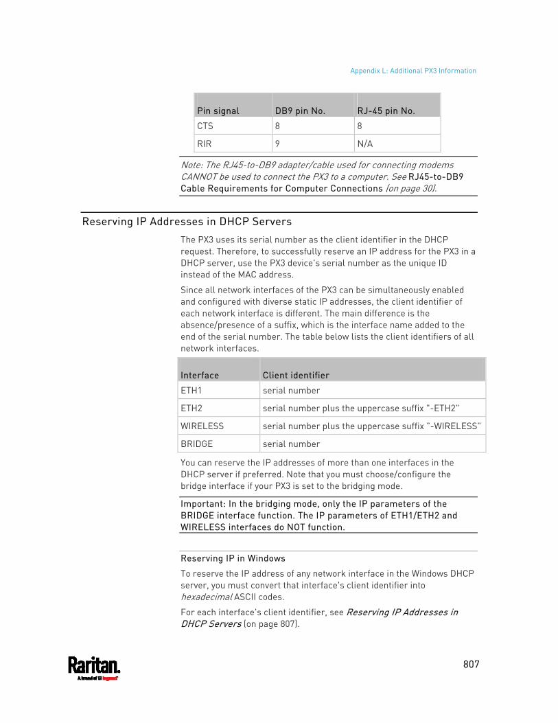
Appendix L: Additional PX3 Information
807
Pin signal DB9 pin No. RJ-45 pin No.
CTS 8 8
RIR 9 N/A
Note: The RJ45-to-DB9 adapter/cable used for connecting modems CANNOT be used to connect the PX3 to a computer. See RJ45-to-DB9 Cable Requirements for Computer Connections (on page 30).
Reserving IP Addresses in DHCP Servers
The PX3 uses its serial number as the client identifier in the DHCP request. Therefore, to successfully reserve an IP address for the PX3 in a DHCP server, use the PX3 device's serial number as the unique ID instead of the MAC address.
Since all network interfaces of the PX3 can be simultaneously enabled and configured with diverse static IP addresses, the client identifier of each network interface is different. The main difference is the absence/presence of a suffix, which is the interface name added to the end of the serial number. The table below lists the client identifiers of all network interfaces.
Interface Client identifier
ETH1 serial number
ETH2 serial number plus the uppercase suffix "-ETH2"
WIRELESS serial number plus the uppercase suffix "-WIRELESS"
BRIDGE serial number
You can reserve the IP addresses of more than one interfaces in the DHCP server if preferred. Note that you must choose/configure the bridge interface if your PX3 is set to the bridging mode.
Important: In the bridging mode, only the IP parameters of the BRIDGE interface function. The IP parameters of ETH1/ETH2 and WIRELESS interfaces do NOT function.
Reserving IP in Windows
To reserve the IP address of any network interface in the Windows DHCP server, you must convert that interface's client identifier into hexadecimal ASCII codes.
For each interface's client identifier, see Reserving IP Addresses in DHCP Servers (on page 807).
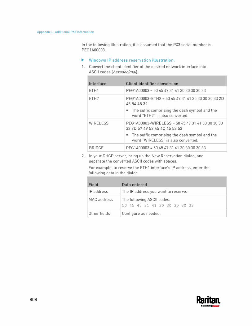
Appendix L: Additional PX3 Information
808
In the following illustration, it is assumed that the PX3 serial number is PEG1A00003.
Windows IP address reservation illustration: 1. Convert the client identifier of the desired network interface into
ASCII codes (hexadecimal).
Interface Client identifier conversion
ETH1 PEG1A00003 = 50 45 47 31 41 30 30 30 30 33
ETH2 PEG1A00003-ETH2 = 50 45 47 31 41 30 30 30 30 33 2D 45 54 48 32 The suffix comprising the dash symbol and the
word "ETH2" is also converted.
WIRELESS PEG1A00003-WIRELESS = 50 45 47 31 41 30 30 30 30 33 2D 57 49 52 45 4C 45 53 53 The suffix comprising the dash symbol and the
word "WIRELESS" is also converted.
BRIDGE PEG1A00003 = 50 45 47 31 41 30 30 30 30 33
2. In your DHCP server, bring up the New Reservation dialog, and separate the converted ASCII codes with spaces. For example, to reserve the ETH1 interface's IP address, enter the following data in the dialog.
Field Data entered
IP address The IP address you want to reserve.
MAC address The following ASCII codes. 50 45 47 31 41 30 30 30 30 33
Other fields Configure as needed.
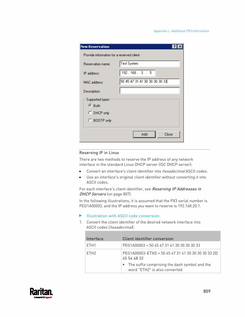
Appendix L: Additional PX3 Information
809
Reserving IP in Linux
There are two methods to reserve the IP address of any network interface in the standard Linux DHCP server (ISC DHCP server):
Convert an interface's client identifier into hexadecimal ASCII codes. Use an interface's original client identifier without converting it into
ASCII codes.
For each interface's client identifier, see Reserving IP Addresses in DHCP Servers (on page 807).
In the following illustrations, it is assumed that the PX3 serial number is PEG1A00003, and the IP address you want to reserve is 192.168.20.1.
Illustration with ASCII code conversion: 1. Convert the client identifier of the desired network interface into
ASCII codes (hexadecimal).
Interface Client identifier conversion
ETH1 PEG1A00003 = 50 45 47 31 41 30 30 30 30 33
ETH2 PEG1A00003-ETH2 = 50 45 47 31 41 30 30 30 30 33 2D 45 54 48 32 The suffix comprising the dash symbol and the
word "ETH2" is also converted.
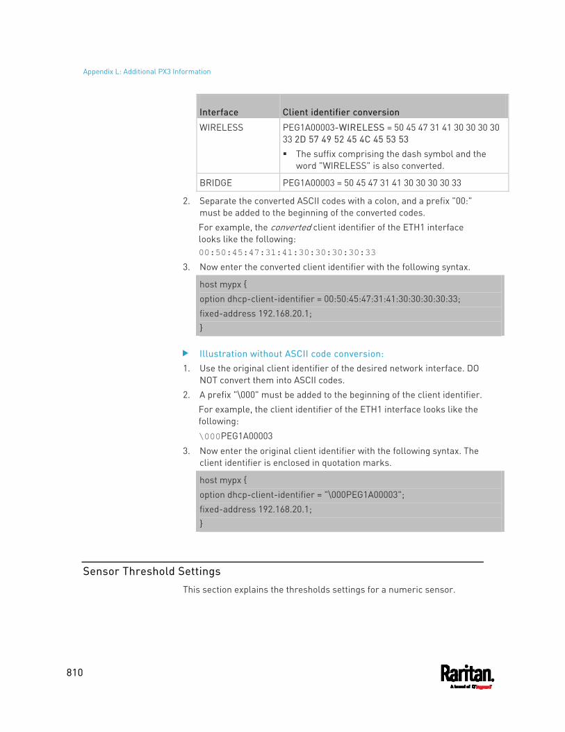
Appendix L: Additional PX3 Information
810
Interface Client identifier conversion
WIRELESS PEG1A00003-WIRELESS = 50 45 47 31 41 30 30 30 30 33 2D 57 49 52 45 4C 45 53 53 The suffix comprising the dash symbol and the
word "WIRELESS" is also converted.
BRIDGE PEG1A00003 = 50 45 47 31 41 30 30 30 30 33
2. Separate the converted ASCII codes with a colon, and a prefix "00:" must be added to the beginning of the converted codes. For example, the converted client identifier of the ETH1 interface looks like the following: 00:50:45:47:31:41:30:30:30:30:33
3. Now enter the converted client identifier with the following syntax.
host mypx { option dhcp-client-identifier = 00:50:45:47:31:41:30:30:30:30:33; fixed-address 192.168.20.1; }
Illustration without ASCII code conversion: 1. Use the original client identifier of the desired network interface. DO
NOT convert them into ASCII codes. 2. A prefix "\000" must be added to the beginning of the client identifier.
For example, the client identifier of the ETH1 interface looks like the following:
\000PEG1A00003
3. Now enter the original client identifier with the following syntax. The client identifier is enclosed in quotation marks.
host mypx { option dhcp-client-identifier = "\000PEG1A00003"; fixed-address 192.168.20.1; }
Sensor Threshold Settings
This section explains the thresholds settings for a numeric sensor.
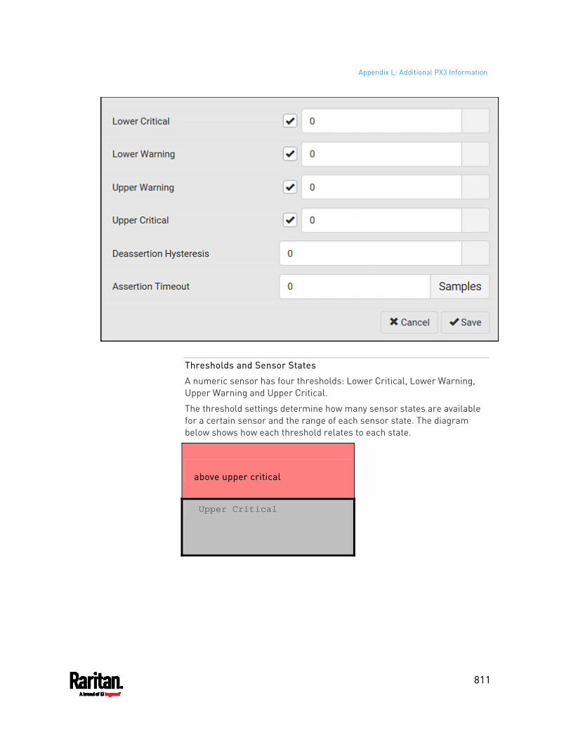
Appendix L: Additional PX3 Information
811
Thresholds and Sensor States
A numeric sensor has four thresholds: Lower Critical, Lower Warning, Upper Warning and Upper Critical.
The threshold settings determine how many sensor states are available for a certain sensor and the range of each sensor state. The diagram below shows how each threshold relates to each state.
above upper critical
Upper Critical
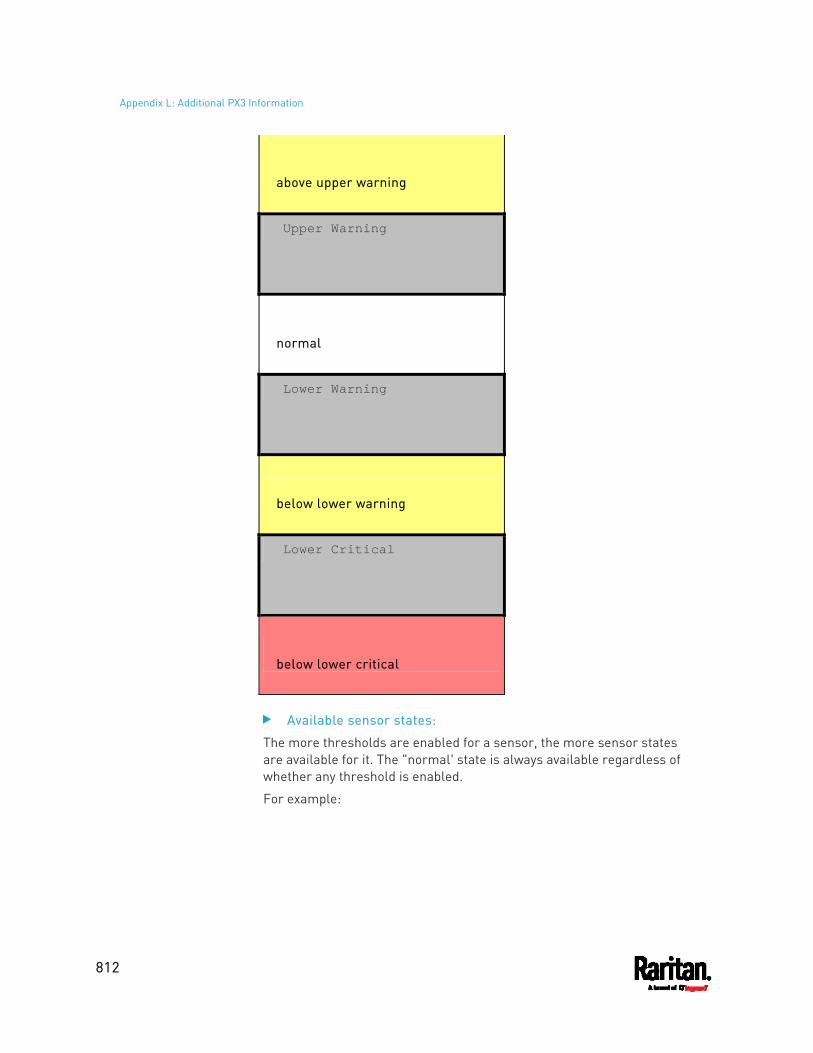
Appendix L: Additional PX3 Information
812
above upper warning
Upper Warning
normal
Lower Warning
below lower warning
Lower Critical
below lower critical
Available sensor states:
The more thresholds are enabled for a sensor, the more sensor states are available for it. The "normal' state is always available regardless of whether any threshold is enabled.
For example:
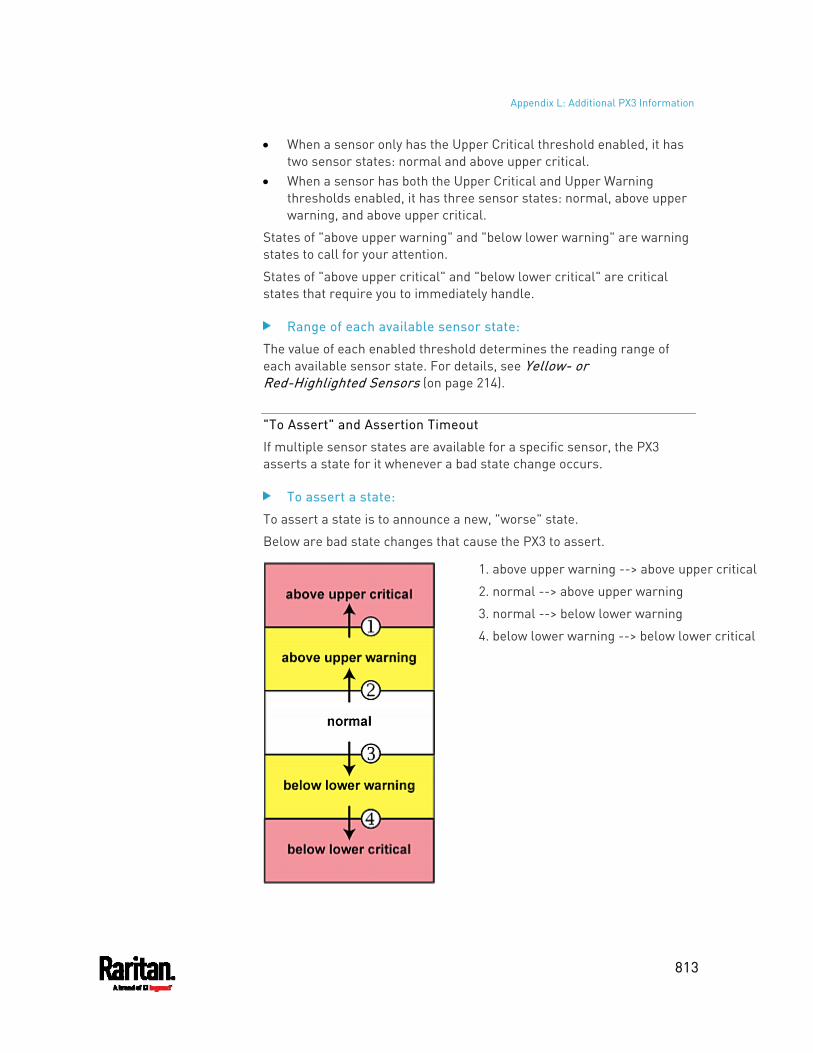
Appendix L: Additional PX3 Information
813
When a sensor only has the Upper Critical threshold enabled, it has two sensor states: normal and above upper critical.
When a sensor has both the Upper Critical and Upper Warning thresholds enabled, it has three sensor states: normal, above upper warning, and above upper critical.
States of "above upper warning" and "below lower warning" are warning states to call for your attention.
States of "above upper critical" and "below lower critical" are critical states that require you to immediately handle.
Range of each available sensor state:
The value of each enabled threshold determines the reading range of each available sensor state. For details, see Yellow- or Red-Highlighted Sensors (on page 214).
"To Assert" and Assertion Timeout
If multiple sensor states are available for a specific sensor, the PX3 asserts a state for it whenever a bad state change occurs.
To assert a state:
To assert a state is to announce a new, "worse" state.
Below are bad state changes that cause the PX3 to assert.
1. above upper warning --> above upper critical
2. normal --> above upper warning
3. normal --> below lower warning
4. below lower warning --> below lower critical
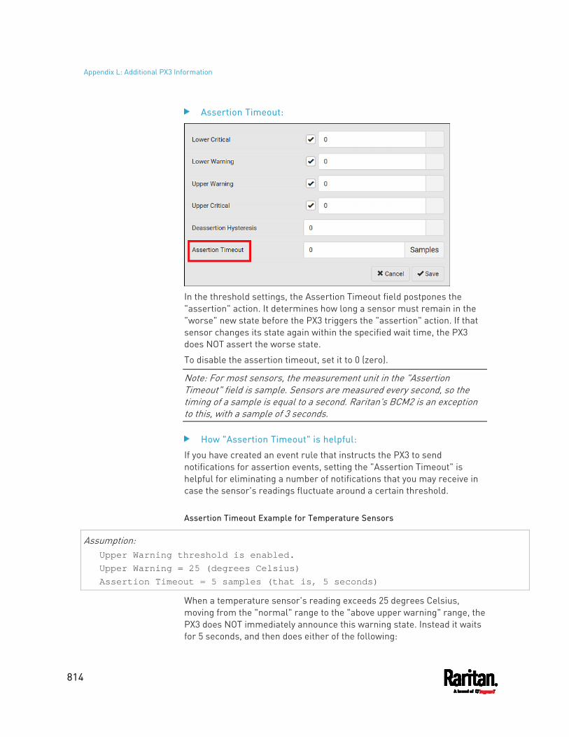
Appendix L: Additional PX3 Information
814
Assertion Timeout:
In the threshold settings, the Assertion Timeout field postpones the "assertion" action. It determines how long a sensor must remain in the "worse" new state before the PX3 triggers the "assertion" action. If that sensor changes its state again within the specified wait time, the PX3 does NOT assert the worse state.
To disable the assertion timeout, set it to 0 (zero).
Note: For most sensors, the measurement unit in the "Assertion Timeout" field is sample. Sensors are measured every second, so the timing of a sample is equal to a second. Raritan's BCM2 is an exception to this, with a sample of 3 seconds.
How "Assertion Timeout" is helpful:
If you have created an event rule that instructs the PX3 to send notifications for assertion events, setting the "Assertion Timeout" is helpful for eliminating a number of notifications that you may receive in case the sensor's readings fluctuate around a certain threshold.
Assertion Timeout Example for Temperature Sensors
Assumption: Upper Warning threshold is enabled. Upper Warning = 25 (degrees Celsius) Assertion Timeout = 5 samples (that is, 5 seconds)
When a temperature sensor's reading exceeds 25 degrees Celsius, moving from the "normal" range to the "above upper warning" range, the PX3 does NOT immediately announce this warning state. Instead it waits for 5 seconds, and then does either of the following:
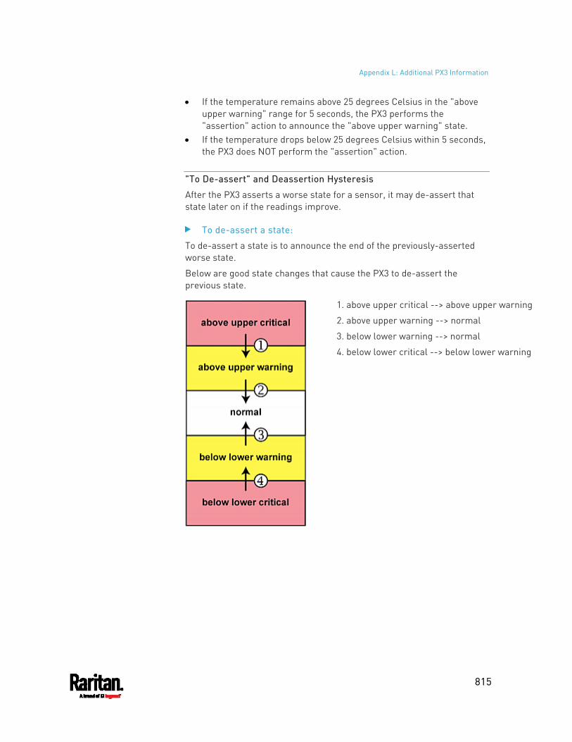
Appendix L: Additional PX3 Information
815
If the temperature remains above 25 degrees Celsius in the "above upper warning" range for 5 seconds, the PX3 performs the "assertion" action to announce the "above upper warning" state.
If the temperature drops below 25 degrees Celsius within 5 seconds, the PX3 does NOT perform the "assertion" action.
"To De-assert" and Deassertion Hysteresis
After the PX3 asserts a worse state for a sensor, it may de-assert that state later on if the readings improve.
To de-assert a state:
To de-assert a state is to announce the end of the previously-asserted worse state.
Below are good state changes that cause the PX3 to de-assert the previous state.
1. above upper critical --> above upper warning
2. above upper warning --> normal
3. below lower warning --> normal
4. below lower critical --> below lower warning
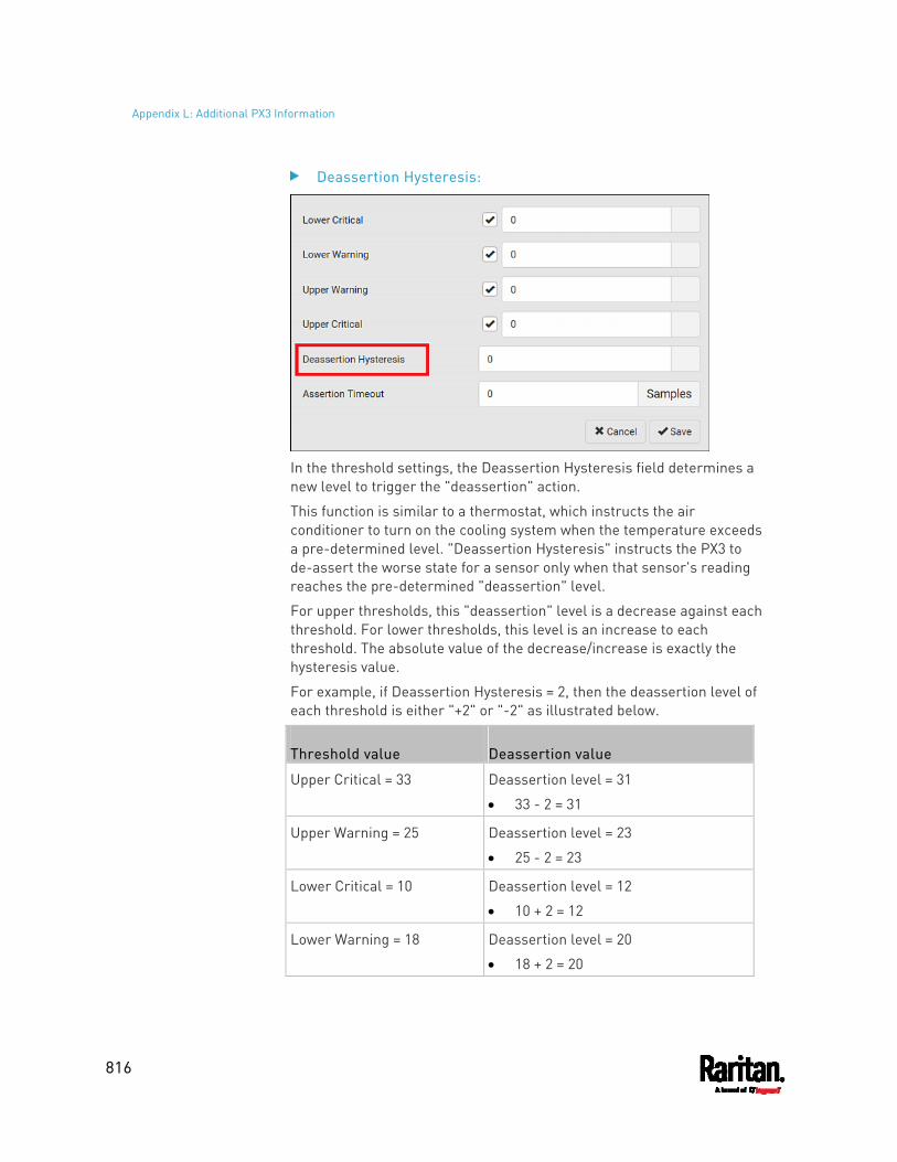
Appendix L: Additional PX3 Information
816
Deassertion Hysteresis:
In the threshold settings, the Deassertion Hysteresis field determines a new level to trigger the "deassertion" action.
This function is similar to a thermostat, which instructs the air conditioner to turn on the cooling system when the temperature exceeds a pre-determined level. "Deassertion Hysteresis" instructs the PX3 to de-assert the worse state for a sensor only when that sensor's reading reaches the pre-determined "deassertion" level.
For upper thresholds, this "deassertion" level is a decrease against each threshold. For lower thresholds, this level is an increase to each threshold. The absolute value of the decrease/increase is exactly the hysteresis value.
For example, if Deassertion Hysteresis = 2, then the deassertion level of each threshold is either "+2" or "-2" as illustrated below.
Threshold value Deassertion value
Upper Critical = 33 Deassertion level = 31
33 - 2 = 31
Upper Warning = 25 Deassertion level = 23
25 - 2 = 23
Lower Critical = 10 Deassertion level = 12
10 + 2 = 12
Lower Warning = 18 Deassertion level = 20
18 + 2 = 20
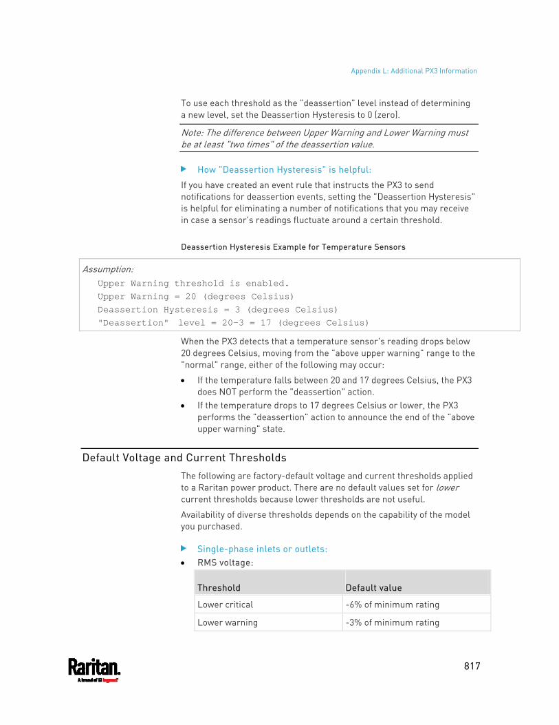
Appendix L: Additional PX3 Information
817
To use each threshold as the "deassertion" level instead of determining a new level, set the Deassertion Hysteresis to 0 (zero).
Note: The difference between Upper Warning and Lower Warning must be at least "two times" of the deassertion value.
How "Deassertion Hysteresis" is helpful:
If you have created an event rule that instructs the PX3 to send notifications for deassertion events, setting the "Deassertion Hysteresis" is helpful for eliminating a number of notifications that you may receive in case a sensor's readings fluctuate around a certain threshold.
Deassertion Hysteresis Example for Temperature Sensors
Assumption: Upper Warning threshold is enabled. Upper Warning = 20 (degrees Celsius) Deassertion Hysteresis = 3 (degrees Celsius) "Deassertion" level = 20-3 = 17 (degrees Celsius)
When the PX3 detects that a temperature sensor's reading drops below 20 degrees Celsius, moving from the "above upper warning" range to the "normal" range, either of the following may occur:
If the temperature falls between 20 and 17 degrees Celsius, the PX3 does NOT perform the "deassertion" action.
If the temperature drops to 17 degrees Celsius or lower, the PX3 performs the "deassertion" action to announce the end of the "above upper warning" state.
Default Voltage and Current Thresholds
The following are factory-default voltage and current thresholds applied to a Raritan power product. There are no default values set for lower current thresholds because lower thresholds are not useful.
Availability of diverse thresholds depends on the capability of the model you purchased.
Single-phase inlets or outlets: RMS voltage:
Threshold Default value
Lower critical -6% of minimum rating
Lower warning -3% of minimum rating
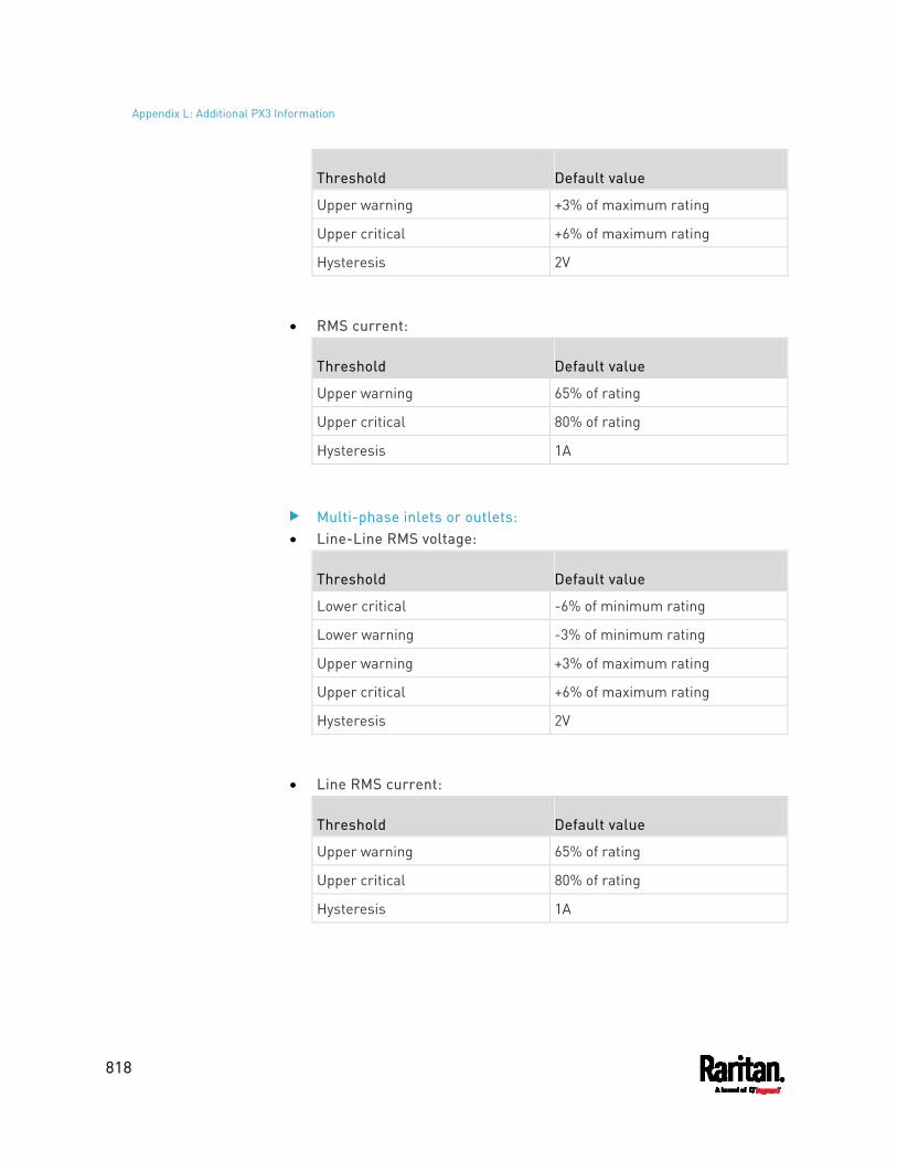
Appendix L: Additional PX3 Information
818
Threshold Default value
Upper warning +3% of maximum rating
Upper critical +6% of maximum rating
Hysteresis 2V
RMS current:
Threshold Default value
Upper warning 65% of rating
Upper critical 80% of rating
Hysteresis 1A
Multi-phase inlets or outlets: Line-Line RMS voltage:
Threshold Default value
Lower critical -6% of minimum rating
Lower warning -3% of minimum rating
Upper warning +3% of maximum rating
Upper critical +6% of maximum rating
Hysteresis 2V
Line RMS current:
Threshold Default value
Upper warning 65% of rating
Upper critical 80% of rating
Hysteresis 1A
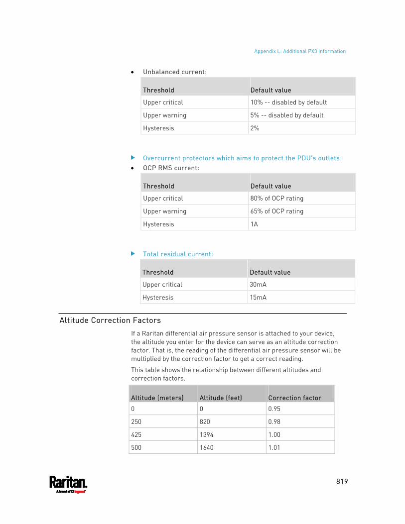
Appendix L: Additional PX3 Information
819
Unbalanced current:
Threshold Default value
Upper critical 10% -- disabled by default
Upper warning 5% -- disabled by default
Hysteresis 2%
Overcurrent protectors which aims to protect the PDU's outlets: OCP RMS current:
Threshold Default value
Upper critical 80% of OCP rating
Upper warning 65% of OCP rating
Hysteresis 1A
Total residual current:
Threshold Default value
Upper critical 30mA
Hysteresis 15mA
Altitude Correction Factors
If a Raritan differential air pressure sensor is attached to your device, the altitude you enter for the device can serve as an altitude correction factor. That is, the reading of the differential air pressure sensor will be multiplied by the correction factor to get a correct reading.
This table shows the relationship between different altitudes and correction factors.
Altitude (meters) Altitude (feet) Correction factor
0 0 0.95
250 820 0.98
425 1394 1.00
500 1640 1.01
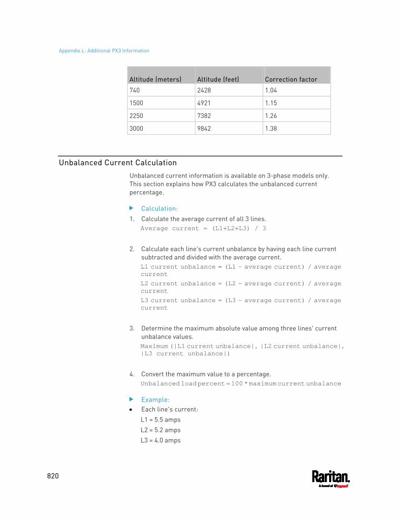
Appendix L: Additional PX3 Information
820
Altitude (meters) Altitude (feet) Correction factor
740 2428 1.04
1500 4921 1.15
2250 7382 1.26
3000 9842 1.38
Unbalanced Current Calculation
Unbalanced current information is available on 3-phase models only. This section explains how PX3 calculates the unbalanced current percentage.
Calculation: 1. Calculate the average current of all 3 lines.
Average current = (L1+L2+L3) / 3
2. Calculate each line's current unbalance by having each line current
subtracted and divided with the average current. L1 current unbalance = (L1 - average current) / average current L2 current unbalance = (L2 - average current) / average current L3 current unbalance = (L3 - average current) / average current
3. Determine the maximum absolute value among three lines' current
unbalance values. Maximum (|L1 current unbalance|, |L2 current unbalance|, |L3 current unbalance|)
4. Convert the maximum value to a percentage.
Unbalanced load percent = 100 * maximum current unbalance
Example: Each line's current:
L1 = 5.5 amps L2 = 5.2 amps L3 = 4.0 amps
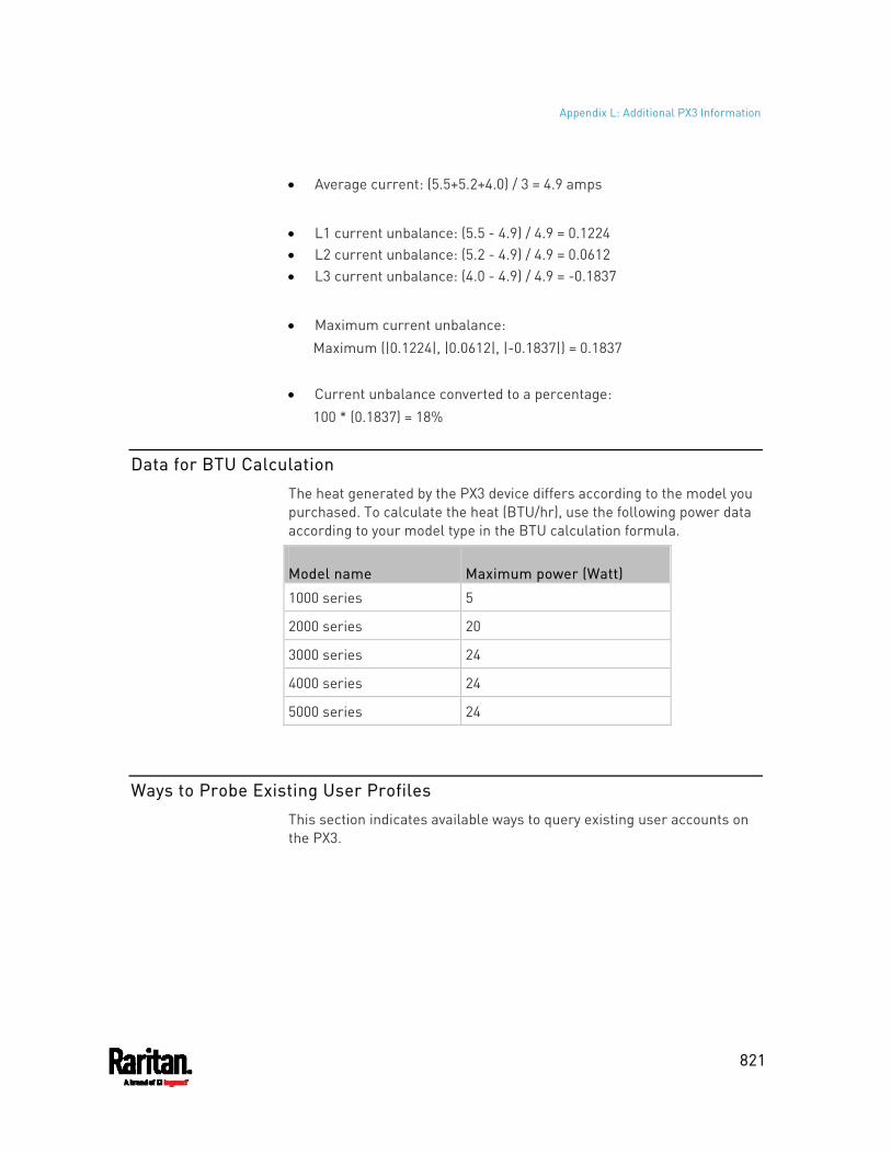
Appendix L: Additional PX3 Information
821
Average current: (5.5+5.2+4.0) / 3 = 4.9 amps
L1 current unbalance: (5.5 - 4.9) / 4.9 = 0.1224 L2 current unbalance: (5.2 - 4.9) / 4.9 = 0.0612 L3 current unbalance: (4.0 - 4.9) / 4.9 = -0.1837
Maximum current unbalance: Maximum (|0.1224|, |0.0612|, |-0.1837|) = 0.1837
Current unbalance converted to a percentage: 100 * (0.1837) = 18%
Data for BTU Calculation
The heat generated by the PX3 device differs according to the model you purchased. To calculate the heat (BTU/hr), use the following power data according to your model type in the BTU calculation formula.
Model name Maximum power (Watt)
1000 series 5
2000 series 20
3000 series 24
4000 series 24
5000 series 24
Ways to Probe Existing User Profiles
This section indicates available ways to query existing user accounts on the PX3.
Appendix L: Additional PX3 Information
822
With SNMP v3 activated, you get the "user unknown" error when the user name used to authenticate does not exist.
Any user with the permission to view event rules can query all local existing users via JSON RPC.
Any user with the permission to view the event log may get information about existing users from the log entries.
Any authenticated users can query currently-existing connection sessions, including Webcam-Live-Preview sessions, which show a list of associated user names.
Raritan Training Website
Raritan offers free training materials for various Raritan products on the Raritan training website http://www.raritantraining.com. The Raritan products introduced on this website include intelligent PDU, KVM, EMX, BCM, and CommandCenter Secure Gateway (CC-SG).
To get access to these training materials or courses, you need to apply for a username and password through the Raritan training website. After you are verified, you can access the Raritan training website anytime.
Role of a DNS Server
As Internet communications are carried out on the basis of IP addresses, appropriate DNS server settings are required for mapping domain names (host names) to corresponding IP addresses, or the PX3 may fail to connect to the given host.
Therefore, DNS server settings are important for external authentication. With appropriate DNS settings, the PX3 can resolve the external authentication server's name to an IP address for establishing a connection. If the SSL/TLS encryption is enabled, the DNS server settings become critical since only fully qualified domain name can be used for specifying the LDAP server.
For information on external authentication, see Setting Up External Authentication (on page 299).
Cascading Troubleshooting
Any accessibility problem occurred on one of the devices in the cascading chain may result in failure to access all downstream slave devices that are connected to it.
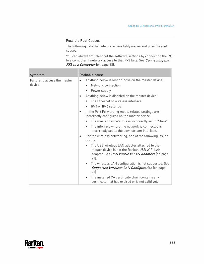
Appendix L: Additional PX3 Information
823
Possible Root Causes
The following lists the network accessibility issues and possible root causes.
You can always troubleshoot the software settings by connecting the PX3 to a computer if network access to that PX3 fails. See Connecting the PX3 to a Computer (on page 28).
Symptom Probable cause
Failure to access the master device
Anything below is lost or loose on the master device: Network connection Power supply
Anything below is disabled on the master device: The Ethernet or wireless interface IPv4 or IPv6 settings
In the Port Forwarding mode, related settings are incorrectly configured on the master device. The master device's role is incorrectly set to 'Slave'. The interface where the network is connected is
incorrectly set as the downstream interface. For the wireless networking, one of the following issues
occurs: The USB wireless LAN adapter attached to the
master device is not the Raritan USB WIFI LAN adapter. See USB Wireless LAN Adapters (on page 21).
The wireless LAN configuration is not supported. See Supported Wireless LAN Configuration (on page 21).
The installed CA certificate chain contains any certificate that has expired or is not valid yet.
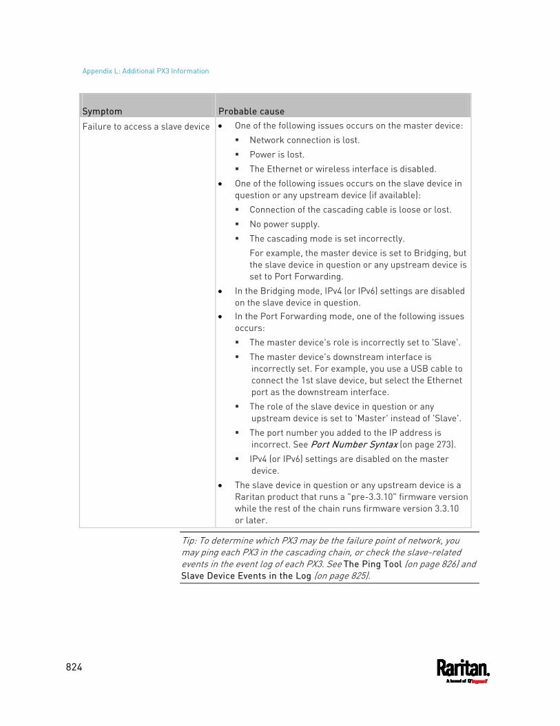
Appendix L: Additional PX3 Information
824
Symptom Probable cause
Failure to access a slave device One of the following issues occurs on the master device: Network connection is lost. Power is lost. The Ethernet or wireless interface is disabled.
One of the following issues occurs on the slave device in question or any upstream device (if available): Connection of the cascading cable is loose or lost. No power supply. The cascading mode is set incorrectly.
For example, the master device is set to Bridging, but the slave device in question or any upstream device is set to Port Forwarding.
In the Bridging mode, IPv4 (or IPv6) settings are disabled on the slave device in question.
In the Port Forwarding mode, one of the following issues occurs: The master device's role is incorrectly set to 'Slave'. The master device's downstream interface is
incorrectly set. For example, you use a USB cable to connect the 1st slave device, but select the Ethernet port as the downstream interface.
The role of the slave device in question or any upstream device is set to 'Master' instead of 'Slave'.
The port number you added to the IP address is incorrect. See Port Number Syntax (on page 273).
IPv4 (or IPv6) settings are disabled on the master device.
The slave device in question or any upstream device is a Raritan product that runs a "pre-3.3.10" firmware version while the rest of the chain runs firmware version 3.3.10 or later.
Tip: To determine which PX3 may be the failure point of network, you may ping each PX3 in the cascading chain, or check the slave-related events in the event log of each PX3. See The Ping Tool (on page 826) and Slave Device Events in the Log (on page 825).
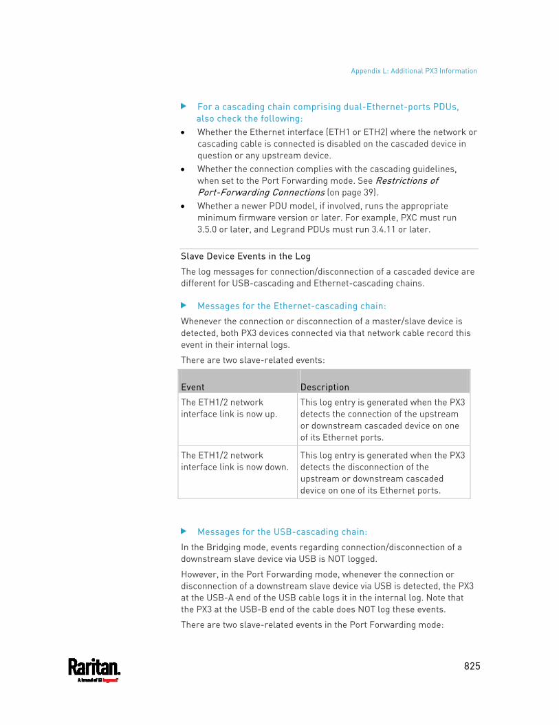
Appendix L: Additional PX3 Information
825
For a cascading chain comprising dual-Ethernet-ports PDUs, also check the following:
Whether the Ethernet interface (ETH1 or ETH2) where the network or cascading cable is connected is disabled on the cascaded device in question or any upstream device.
Whether the connection complies with the cascading guidelines, when set to the Port Forwarding mode. See Restrictions of Port-Forwarding Connections (on page 39).
Whether a newer PDU model, if involved, runs the appropriate minimum firmware version or later. For example, PXC must run 3.5.0 or later, and Legrand PDUs must run 3.4.11 or later.
Slave Device Events in the Log
The log messages for connection/disconnection of a cascaded device are different for USB-cascading and Ethernet-cascading chains.
Messages for the Ethernet-cascading chain:
Whenever the connection or disconnection of a master/slave device is detected, both PX3 devices connected via that network cable record this event in their internal logs.
There are two slave-related events:
Event Description
The ETH1/2 network interface link is now up.
This log entry is generated when the PX3 detects the connection of the upstream or downstream cascaded device on one of its Ethernet ports.
The ETH1/2 network interface link is now down.
This log entry is generated when the PX3 detects the disconnection of the upstream or downstream cascaded device on one of its Ethernet ports.
Messages for the USB-cascading chain:
In the Bridging mode, events regarding connection/disconnection of a downstream slave device via USB is NOT logged.
However, in the Port Forwarding mode, whenever the connection or disconnection of a downstream slave device via USB is detected, the PX3 at the USB-A end of the USB cable logs it in the internal log. Note that the PX3 at the USB-B end of the cable does NOT log these events.
There are two slave-related events in the Port Forwarding mode:
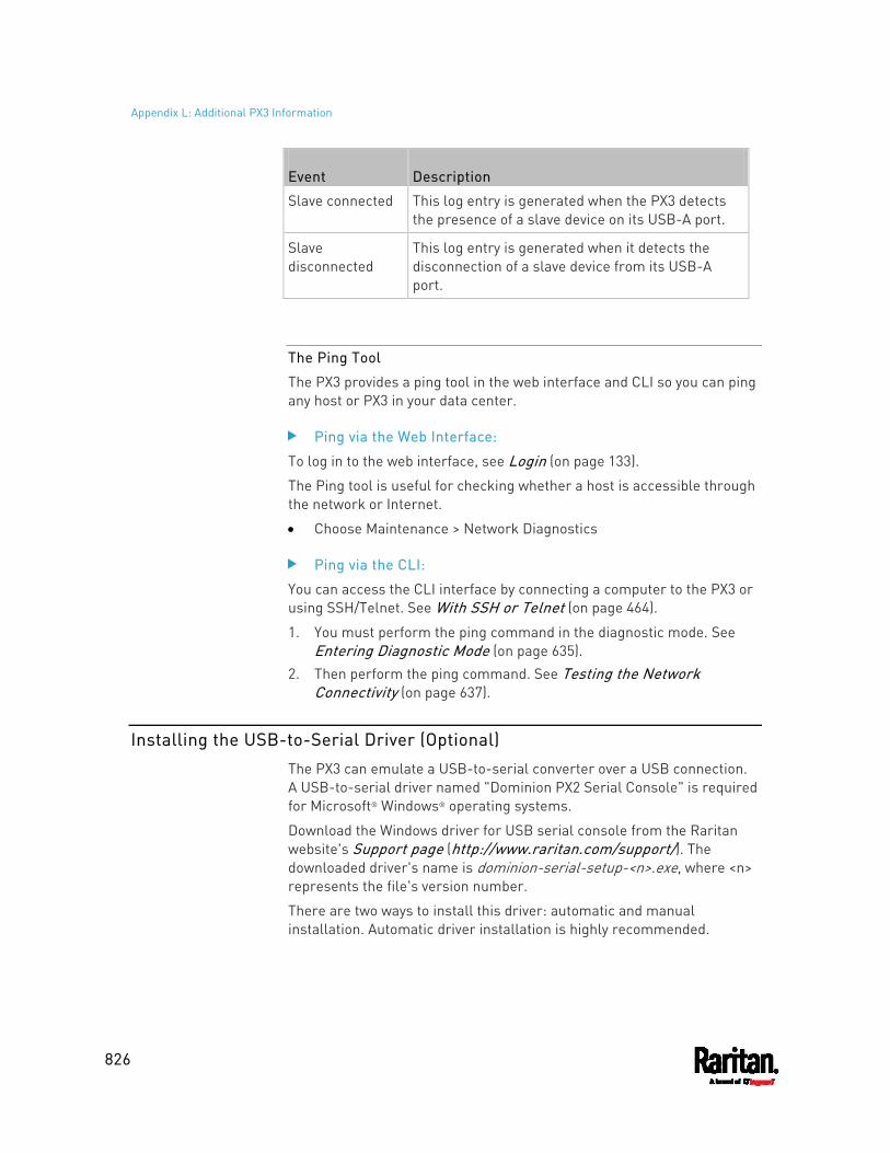
Appendix L: Additional PX3 Information
826
Event Description
Slave connected This log entry is generated when the PX3 detects the presence of a slave device on its USB-A port.
Slave disconnected
This log entry is generated when it detects the disconnection of a slave device from its USB-A port.
The Ping Tool
The PX3 provides a ping tool in the web interface and CLI so you can ping any host or PX3 in your data center.
Ping via the Web Interface:
To log in to the web interface, see Login (on page 133).
The Ping tool is useful for checking whether a host is accessible through the network or Internet.
Choose Maintenance > Network Diagnostics
Ping via the CLI:
You can access the CLI interface by connecting a computer to the PX3 or using SSH/Telnet. See With SSH or Telnet (on page 464).
1. You must perform the ping command in the diagnostic mode. See Entering Diagnostic Mode (on page 635).
2. Then perform the ping command. See Testing the Network Connectivity (on page 637).
Installing the USB-to-Serial Driver (Optional)
The PX3 can emulate a USB-to-serial converter over a USB connection. A USB-to-serial driver named "Dominion PX2 Serial Console" is required for Microsoft® Windows® operating systems.
Download the Windows driver for USB serial console from the Raritan website's Support page (http://www.raritan.com/support/). The downloaded driver's name is dominion-serial-setup-<n>.exe, where <n> represents the file's version number.
There are two ways to install this driver: automatic and manual installation. Automatic driver installation is highly recommended.
Appendix L: Additional PX3 Information
827
Automatic driver installation in Windows®: 1. Make sure the PX3 is NOT connected to the computer via a USB
cable. 2. Run dominion-serial-setup-<n>.exe on the computer and follow
online instructions to install the driver.
Note: If any Windows security warning appears, accept it to continue the installation.
3. Connect the PX3 to the computer via a USB cable. The driver is automatically installed.
Manual driver installation in Windows®: 1. Make sure the PX3 has been connected to the computer via a USB
cable. 2. The computer detects the new device and the "Found New Hardware
Wizard" dialog appears. If this dialog does not appear, choose Control Panel > System >
Hardware > Device Manager, right-click the Dominion PX2 Serial Console, and choose Update Driver.
3. Select the option of driver installation from a specific location, and then specify the location where both dominion-serial.inf and dominion-serial.cat are stored.
Note: If any Windows security warning appears, accept it to continue the installation.
4. Wait until the installation is complete.
Note: If the PX3 enters the disaster recovery mode when the USB serial driver is not installed yet, it may be shown as a 'GPS camera' in the Device Manager on the computer connected to it.
In Linux:
No additional drivers are required, but you must provide the name of the tty device, which can be found in the output of the "dmesg" after connecting the PX3 to the computer. Usually the tty device is "/dev/ttyACM#" or "/dev/ttyUSB#," where # is an integer number.
For example, if you are using the kermit terminal program, and the tty device is "/dev/ttyACM0," perform the following commands:
> set line /dev/ttyACM0
> Connect
Appendix L: Additional PX3 Information
828
Initial Network Configuration via CLI
After the PX3 is connected to your network, you must provide it with an IP address and some additional networking information.
This section describes the initial network configuration via a serial RS-232 or USB connection. To configure the network settings using the web interface, see Configuring Network Settings (on page 256).
To configure the PX3 device: 1. On the computer connected to the PX3, open a communications
program such as HyperTerminal or PuTTY. 2. Select the appropriate COM port, and set the following port settings:
Bits per second = 115200 (115.2Kbps) Data bits = 8 Stop bits = 1 Parity = None Flow control = None
Tip: For a USB connection, you can determine the COM port by choosing Control Panel > System > Hardware > Device Manager, and locating the "Dominion PX2 Serial Console" under the Ports group.
3. In the communications program, press Enter to send a carriage return to the PX3.
4. The PX3 prompts you to log in. Both user name and password are case sensitive.
a. Username: admin
b. Default password: raritan (or a new password if you have changed it).
5. If prompted to change the default password, change or ignore it. To change it, follow onscreen instructions to type your new
password. To ignore it, simply press Enter.
6. The # prompt appears.
7. Type config and press Enter.
8. To configure network settings, type appropriate commands and press Enter. Refer to the following commands list. CLI commands are case sensitive.
9. After finishing the network settings, type apply to save changes. To abort, type cancel.
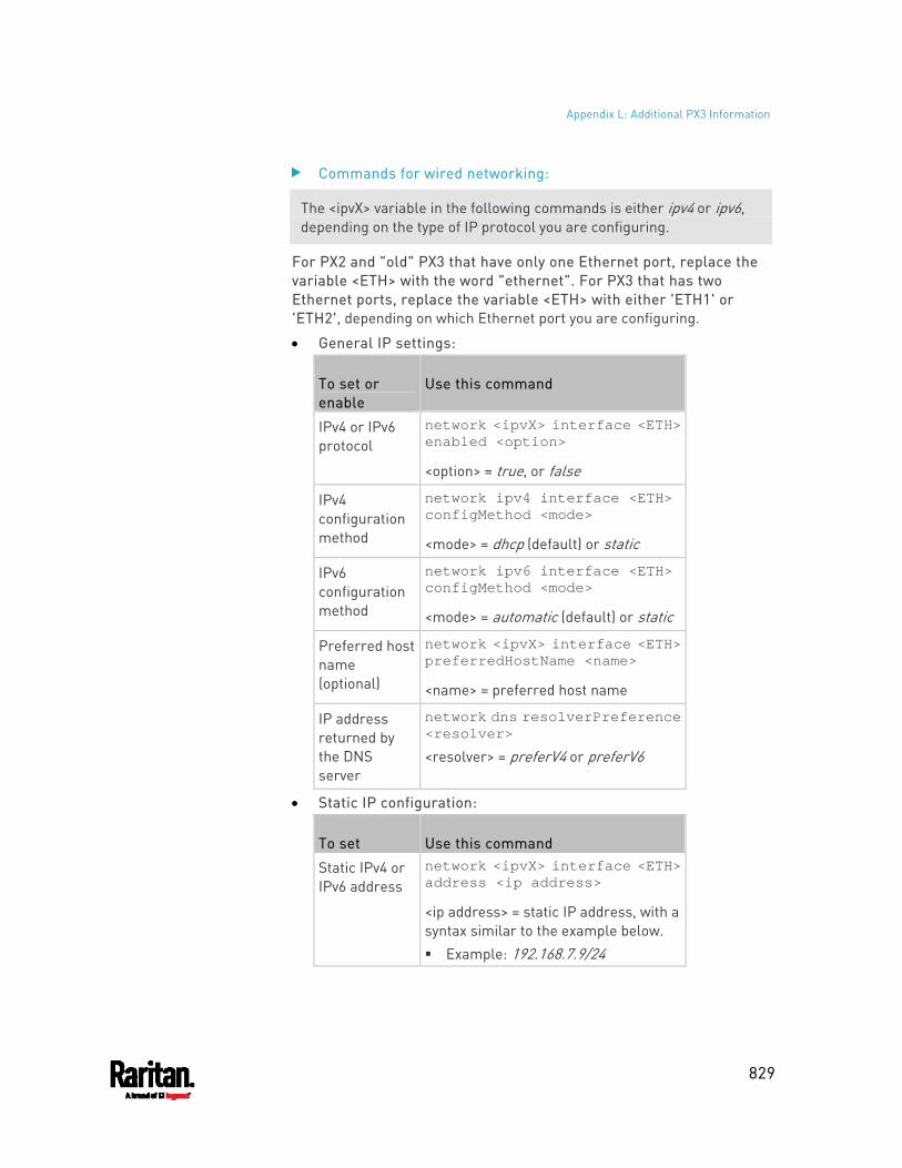
Appendix L: Additional PX3 Information
829
Commands for wired networking:
The <ipvX> variable in the following commands is either ipv4 or ipv6, depending on the type of IP protocol you are configuring.
For PX2 and "old" PX3 that have only one Ethernet port, replace the variable <ETH> with the word "ethernet". For PX3 that has two Ethernet ports, replace the variable <ETH> with either 'ETH1' or 'ETH2', depending on which Ethernet port you are configuring.
General IP settings:
To set or enable
Use this command
IPv4 or IPv6 protocol
network <ipvX> interface <ETH> enabled <option>
<option> = true, or false
IPv4 configuration method
network ipv4 interface <ETH> configMethod <mode>
<mode> = dhcp (default) or static
IPv6 configuration method
network ipv6 interface <ETH> configMethod <mode>
<mode> = automatic (default) or static
Preferred host name (optional)
network <ipvX> interface <ETH> preferredHostName <name>
<name> = preferred host name
IP address returned by the DNS server
network dns resolverPreference <resolver>
<resolver> = preferV4 or preferV6
Static IP configuration:
To set Use this command
Static IPv4 or IPv6 address
network <ipvX> interface <ETH> address <ip address>
<ip address> = static IP address, with a syntax similar to the example below. Example: 192.168.7.9/24
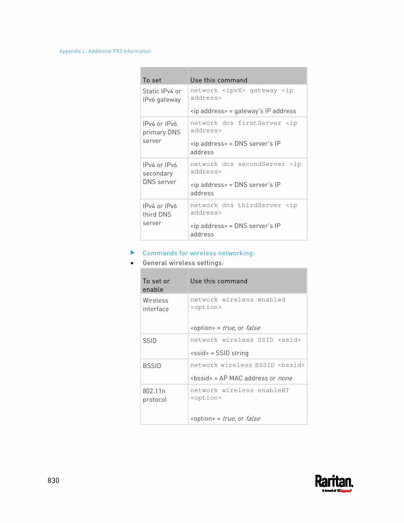
Appendix L: Additional PX3 Information
830
To set Use this command
Static IPv4 or IPv6 gateway
network <ipvX> gateway <ip address>
<ip address> = gateway's IP address
IPv4 or IPv6 primary DNS server
network dns firstServer <ip address>
<ip address> = DNS server's IP address
IPv4 or IPv6 secondary DNS server
network dns secondServer <ip address>
<ip address> = DNS server's IP address
IPv4 or IPv6 third DNS server
network dns thirdServer <ip address>
<ip address> = DNS server's IP address
Commands for wireless networking: General wireless settings:
To set or enable
Use this command
Wireless interface
network wireless enabled <option>
<option> = true, or false
SSID network wireless SSID <ssid>
<ssid> = SSID string
BSSID network wireless BSSID <bssid>
<bssid> = AP MAC address or none
802.11n protocol
network wireless enableHT <option>
<option> = true, or false
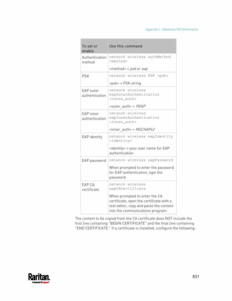
Appendix L: Additional PX3 Information
831
To set or enable
Use this command
Authentication method
network wireless authMethod <method>
<method> = psk or eap
PSK network wireless PSK <psk>
<psk> = PSK string
EAP outer authentication
network wireless eapOuterAuthentication <outer_auth>
<outer_auth> = PEAP
EAP inner authentication
network wireless eapInnerAuthentication <inner_auth>
<inner_auth> = MSCHAPv2
EAP identity network wireless eapIdentity <identity>
<identity> = your user name for EAP authentication
EAP password network wireless eapPassword
When prompted to enter the password for EAP authentication, type the password.
EAP CA certificate
network wireless eapCACertificate
When prompted to enter the CA certificate, open the certificate with a text editor, copy and paste the content into the communications program.
The content to be copied from the CA certificate does NOT include the first line containing "BEGIN CERTIFICATE" and the final line containing "END CERTIFICATE." If a certificate is installed, configure the following:
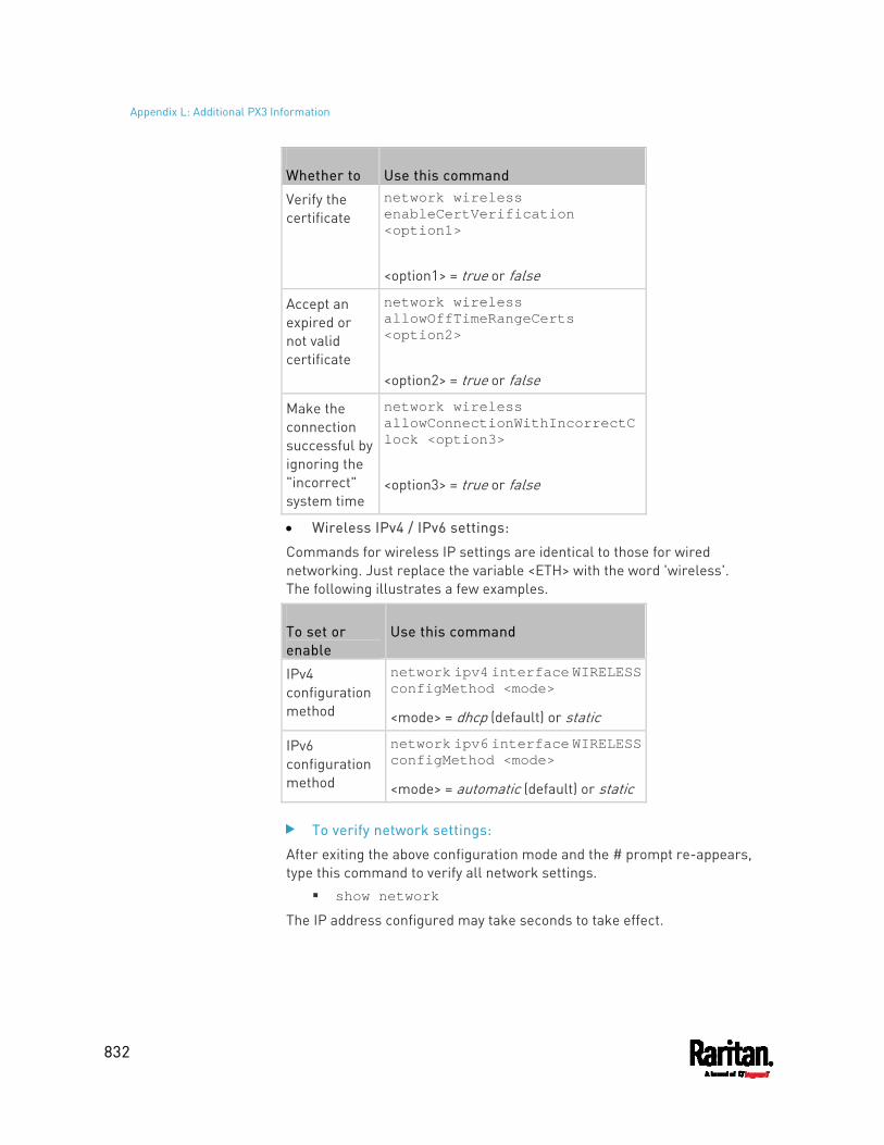
Appendix L: Additional PX3 Information
832
Whether to Use this command
Verify the certificate
network wireless enableCertVerification <option1>
<option1> = true or false
Accept an expired or not valid certificate
network wireless allowOffTimeRangeCerts <option2>
<option2> = true or false
Make the connection successful by ignoring the "incorrect" system time
network wireless allowConnectionWithIncorrectClock <option3>
<option3> = true or false
Wireless IPv4 / IPv6 settings:
Commands for wireless IP settings are identical to those for wired networking. Just replace the variable <ETH> with the word 'wireless'. The following illustrates a few examples.
To set or enable
Use this command
IPv4 configuration method
network ipv4 interface WIRELESS configMethod <mode>
<mode> = dhcp (default) or static
IPv6 configuration method
network ipv6 interface WIRELESS configMethod <mode>
<mode> = automatic (default) or static
To verify network settings:
After exiting the above configuration mode and the # prompt re-appears, type this command to verify all network settings.
show network
The IP address configured may take seconds to take effect.
Appendix L: Additional PX3 Information
833
Device-Specific Settings
A bulk configuration file will NOT contain any device-specific information like the following list.
For further information, simply open the built-in bulk profile for a detailed list of 'excluded' settings.
Device name SNMP system name, contact and location Part of network settings (IP address, gateway, netmask and so on) Device logs Names, states and values of environmental sensors and actuators TLS certificate Server monitoring entries Asset strip names and rack unit names Outlet names and states
TLS Certificate Chain
A TLS server sends out a certificate to any client attempting to connect to it. The receiver determines whether a TLS server can be trusted by verifying that server's certificate, using the certificate (chain) stored on the receiver.
Therefore, to successfully connect to a TLS server, you must upload a valid certificate or (partial) certificate chain to the receiver.
The uploaded certificate (chain) must contain all missing certificates "related to" that TLS server's certificate in some way. Otherwise, the connection made to that TLS server will fail.
For information on how the uploaded certificate (chain) is related to a TLS server's certificate, see What is a Certificate Chain (on page 833).
For an example of creating and uploading a TLS certificate to PX3, see Illustration - GMAIL SMTP Certificate Chain (on page 837).
What is a Certificate Chain
If you are familiar with a certificate chain, you can ignore this topic and refer to Illustration - GMAIL SMTP Certificate Chain (on page 837).
A certificate or a chain of certificates is used for trusting a TLS server that you want to connect.
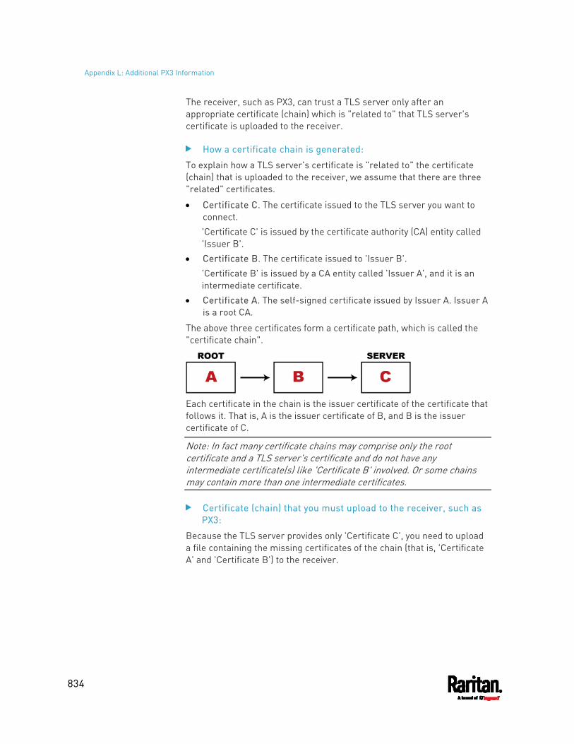
Appendix L: Additional PX3 Information
834
The receiver, such as PX3, can trust a TLS server only after an appropriate certificate (chain) which is "related to" that TLS server's certificate is uploaded to the receiver.
How a certificate chain is generated:
To explain how a TLS server's certificate is "related to" the certificate (chain) that is uploaded to the receiver, we assume that there are three "related" certificates.
Certificate C. The certificate issued to the TLS server you want to connect. 'Certificate C' is issued by the certificate authority (CA) entity called 'Issuer B'.
Certificate B. The certificate issued to 'Issuer B'. 'Certificate B' is issued by a CA entity called 'Issuer A', and it is an intermediate certificate.
Certificate A. The self-signed certificate issued by Issuer A. Issuer A is a root CA.
The above three certificates form a certificate path, which is called the "certificate chain".
Each certificate in the chain is the issuer certificate of the certificate that follows it. That is, A is the issuer certificate of B, and B is the issuer certificate of C.
Note: In fact many certificate chains may comprise only the root certificate and a TLS server's certificate and do not have any intermediate certificate(s) like 'Certificate B' involved. Or some chains may contain more than one intermediate certificates.
Certificate (chain) that you must upload to the receiver, such as PX3:
Because the TLS server provides only 'Certificate C', you need to upload a file containing the missing certificates of the chain (that is, 'Certificate A' and 'Certificate B') to the receiver.
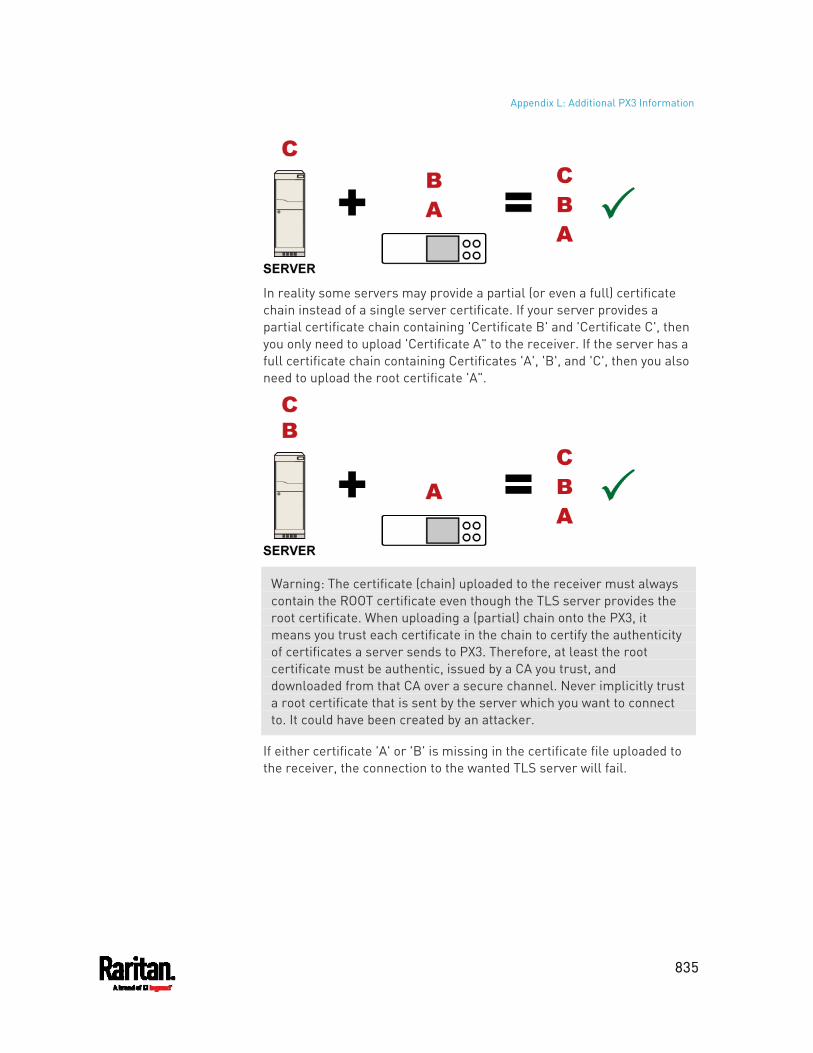
Appendix L: Additional PX3 Information
835
In reality some servers may provide a partial (or even a full) certificate chain instead of a single server certificate. If your server provides a partial certificate chain containing 'Certificate B' and 'Certificate C', then you only need to upload 'Certificate A" to the receiver. If the server has a full certificate chain containing Certificates 'A', 'B', and 'C', then you also need to upload the root certificate 'A".
Warning: The certificate (chain) uploaded to the receiver must always contain the ROOT certificate even though the TLS server provides the root certificate. When uploading a (partial) chain onto the PX3, it means you trust each certificate in the chain to certify the authenticity of certificates a server sends to PX3. Therefore, at least the root certificate must be authentic, issued by a CA you trust, and downloaded from that CA over a secure channel. Never implicitly trust a root certificate that is sent by the server which you want to connect to. It could have been created by an attacker.
If either certificate 'A' or 'B' is missing in the certificate file uploaded to the receiver, the connection to the wanted TLS server will fail.
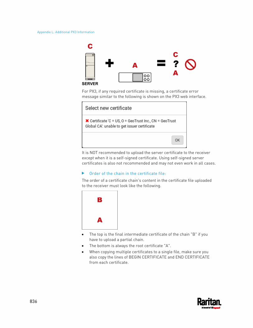
Appendix L: Additional PX3 Information
836
For PX3, if any required certificate is missing, a certificate error message similar to the following is shown on the PX3 web interface.
It is NOT recommended to upload the server certificate to the receiver except when it is a self-signed certificate. Using self-signed server certificates is also not recommended and may not even work in all cases.
Order of the chain in the certificate file:
The order of a certificate chain's content in the certificate file uploaded to the receiver must look like the following.
The top is the final intermediate certificate of the chain "B" if you
have to upload a partial chain. The bottom is always the root certificate "A". When copying multiple certificates to a single file, make sure you
also copy the lines of BEGIN CERTIFICATE and END CERTIFICATE from each certificate.
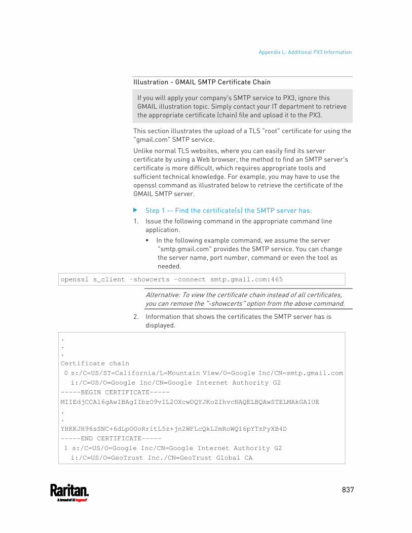
Appendix L: Additional PX3 Information
837
Illustration - GMAIL SMTP Certificate Chain
If you will apply your company's SMTP service to PX3, ignore this GMAIL illustration topic. Simply contact your IT department to retrieve the appropriate certificate (chain) file and upload it to the PX3.
This section illustrates the upload of a TLS "root" certificate for using the "gmail.com" SMTP service.
Unlike normal TLS websites, where you can easily find its server certificate by using a Web browser, the method to find an SMTP server's certificate is more difficult, which requires appropriate tools and sufficient technical knowledge. For example, you may have to use the openssl command as illustrated below to retrieve the certificate of the GMAIL SMTP server.
Step 1 -- Find the certificate(s) the SMTP server has: 1. Issue the following command in the appropriate command line
application. In the following example command, we assume the server
"smtp.gmail.com" provides the SMTP service. You can change the server name, port number, command or even the tool as needed.
openssl s_client -showcerts -connect smtp.gmail.com:465
Alternative: To view the certificate chain instead of all certificates, you can remove the "-showcerts" option from the above command.
2. Information that shows the certificates the SMTP server has is displayed.
.
.
. Certificate chain 0 s:/C=US/ST=California/L=Mountain View/O=Google Inc/CN=smtp.gmail.com
i:/C=US/O=Google Inc/CN=Google Internet Authority G2 -----BEGIN CERTIFICATE----- MIIEdjCCA16gAwIBAgIIbzO9vIL2OXcwDQYJKoZIhvcNAQELBQAwSTELMAkGA1UE . . YHKKJH96sSNC+6dLpOOoRritL5z+jn2WFLcQkL2mRoWQi6pYTzPyXB4D -----END CERTIFICATE----- 1 s:/C=US/O=Google Inc/CN=Google Internet Authority G2 i:/C=US/O=GeoTrust Inc./CN=GeoTrust Global CA
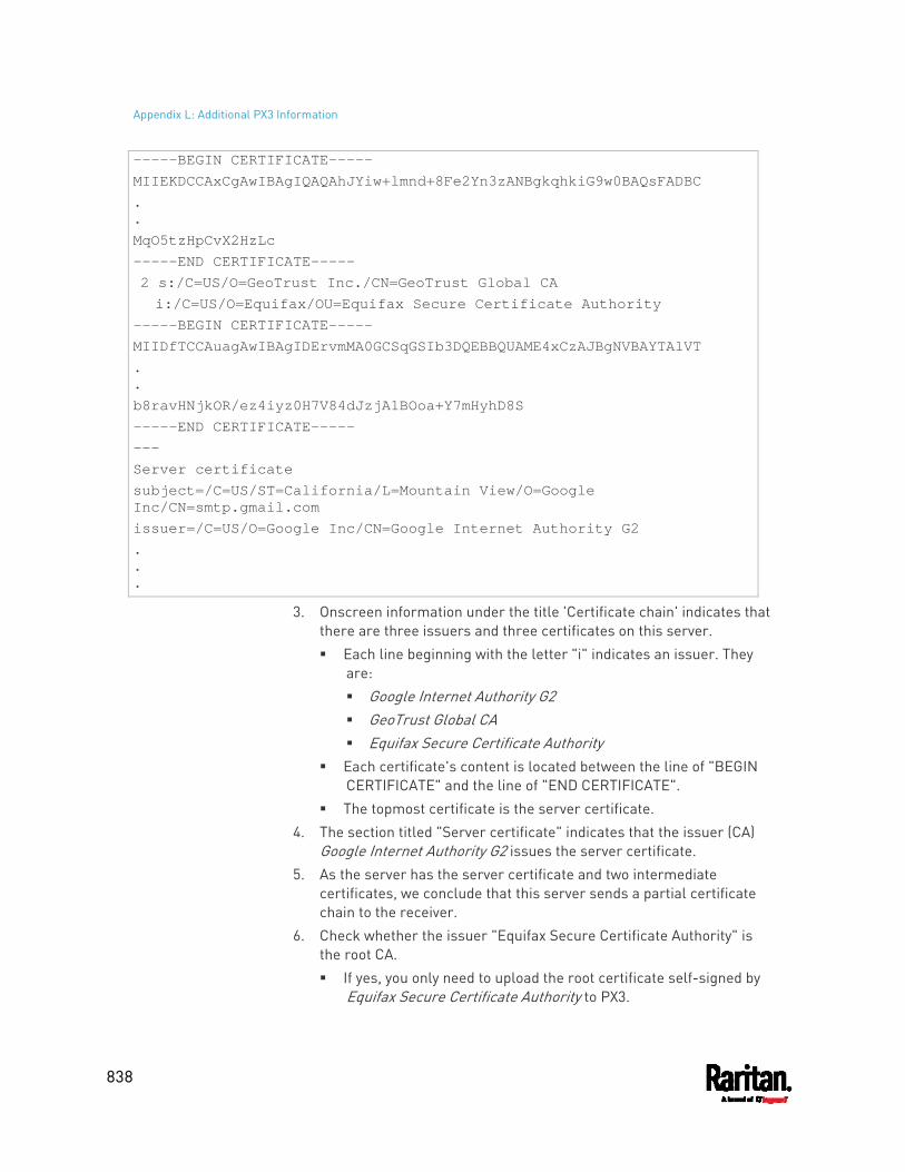
Appendix L: Additional PX3 Information
838
-----BEGIN CERTIFICATE----- MIIEKDCCAxCgAwIBAgIQAQAhJYiw+lmnd+8Fe2Yn3zANBgkqhkiG9w0BAQsFADBC . . MqO5tzHpCvX2HzLc -----END CERTIFICATE----- 2 s:/C=US/O=GeoTrust Inc./CN=GeoTrust Global CA i:/C=US/O=Equifax/OU=Equifax Secure Certificate Authority -----BEGIN CERTIFICATE----- MIIDfTCCAuagAwIBAgIDErvmMA0GCSqGSIb3DQEBBQUAME4xCzAJBgNVBAYTAlVT . . b8ravHNjkOR/ez4iyz0H7V84dJzjA1BOoa+Y7mHyhD8S -----END CERTIFICATE----- --- Server certificate subject=/C=US/ST=California/L=Mountain View/O=Google Inc/CN=smtp.gmail.com issuer=/C=US/O=Google Inc/CN=Google Internet Authority G2 . . .
3. Onscreen information under the title 'Certificate chain' indicates that there are three issuers and three certificates on this server. Each line beginning with the letter "i" indicates an issuer. They
are: Google Internet Authority G2 GeoTrust Global CA Equifax Secure Certificate Authority
Each certificate's content is located between the line of "BEGIN CERTIFICATE" and the line of "END CERTIFICATE".
The topmost certificate is the server certificate. 4. The section titled "Server certificate" indicates that the issuer (CA)
Google Internet Authority G2 issues the server certificate. 5. As the server has the server certificate and two intermediate
certificates, we conclude that this server sends a partial certificate chain to the receiver.
6. Check whether the issuer "Equifax Secure Certificate Authority" is the root CA. If yes, you only need to upload the root certificate self-signed by
Equifax Secure Certificate Authority to PX3.
Appendix L: Additional PX3 Information
839
If not, you need to find all missing issuer certificates, including the root certificate, and upload them to PX3.
Step 2 -- Find and download the content of missing issuer certificate(s):
1. View the name of the issuer (CA) at the bottom. In this example, this issuer is 'Equifax Secure Certificate Authority'.
2. Use the issuer's name 'Equifax Secure Certificate Authority' to search for its certificate on the Internet, and then download or copy the content from an authentic source, which is usually its official website.
Important: To prevent the downloaded certificate from being modified or manipulated, you must secure the download with TLS via a trusted certificate.
3. As it is found the Equifax Secure Certificate Authority's certificate is self signed by 'Equifax Secure Certificate Authority', which indicates it is the root CA, there are no more missing certificates to search for.
Step 3 -- Upload the missing certificate(s) to PX3: 1. Paste the root certificate's content into a plain text file that will be
uploaded to PX3. Content copying must include the lines of "BEGIN CERTIFICATE"
and "END CERTIFICATE". 2. Save that file as a .pem, .crt or .cer file. In this example, it is named
as "my-root.pem." 3. Upload the file "my-root.pem" to PX3 for using the GMAIL SMTP
service.
Note: If your SMTP server requires the upload of a certificate file comprising multiple certificates, make sure the order of these certificates is correct in the file. See What is a Certificate Chain (on page 833).
IMPORTANT NOTE:
If your SMTP server provides a full certificate chain, you should be suspicious whether any attacker fakes the certificate chain and doubt whether the root certificate on that server is authentic. It is STRONGLY recommended to download the root certificate from an authentic source, which is usually the root CA's website, rather than from the server you want to connect.
Appendix L: Additional PX3 Information
840
Browsing through the Online Help
The PX3 Online Help is accessible over the Internet.
To use online help, Active Content must be enabled in your browser. Consult your browser help for information on enabling the feature.
To use the PX3 online help: 1. Click Online Documentation. See Web Interface Overview (on page
137). 2. The online help opens in the default web browser. 3. To view the content of any topic, click the topic in the left pane. Then
its content is displayed in the right pane. 4. To select a different topic, do any of the following:
To view the next topic, click the Next icon in the toolbar.
To view the previous topic, click the Previous icon .
To view the first topic, click the Home icon . 5. To expand or collapse a topic that contains sub-topics, do the
following: To expand any topic, click the white arrow prior to the topic, or
double-click that topic. The arrow turns into a black, gradient arrow , and sub-topics appear below the topic.
To collapse any expanded topic, click the black, gradient arrow prior to the topic, or double-click the expanded topic. The arrow then turns into a white arrow , and all sub-topics below that topic disappear.
6. To search for specific information, type the key word(s) or string(s) in the Search text box, and press Enter or click the Search icon to start the search. If necessary, select the "Match partial words" checkbox to
include information matching part of the words entered in the Search text box.
The search results are displayed in the left pane. 7. To have the left pane show the list of topics, click the Contents tab at
the bottom. 8. To show the Index page, click the Index tab. 9. To email any URL link to the currently selected topic to any person,
click the "Email this page" icon in the toolbar. 10. To email your comments or suggestions regarding the online help to
Raritan, click the "Send feedback" icon .

Appendix L: Additional PX3 Information
841
11. To print the currently selected topic, click the "Print this page" icon .
842
The PX3 can work with certain Raritan or third-party products to provide diverse power solutions.
In This Chapter
Dominion KX II / III Configuration............................................................ 842 Dominion KSX II, SX or SX II Configuration ............................................. 847 Power IQ Configuration ........................................................................... 852 dcTrack .................................................................................................... 852
Dominion KX II / III Configuration
Raritan PX2, PX3 or PX3TS series can be connected to the Raritan's Dominion KX II or KX III device (a digital KVM switch) to provide one more alternative of power management.
Note that this integration requires the following firmware versions:
Dominion KX II -- 2.4 or later Dominion KX III -- ALL versions PX2 series -- 2.2 or later PX3 series -- 2.5.10 or later PX3TS series -- 2.6.1 or later
Dominion KX II or KX III integration requires D2CIM-PWR and straight CAT5 cable.
For more information on KX II / III, refer to:
KX II or KX III User Guide on the Support page (http://www.raritan.com/support/)
KX II or KX III Online Help on the Product Online Help page (http://www.raritan.com/support/online-help/)
Note: For documentation conveniences, both Dominion KX II and KX III products are referred to as "KX III" in the following sections.
Configuring Rack PDU Targets
KX III allows you to connect rack PDUs (power strips) to KX III ports.
KX III rack PDU configuration is done from the KX III Port Configuration page.
Appendix M Integration
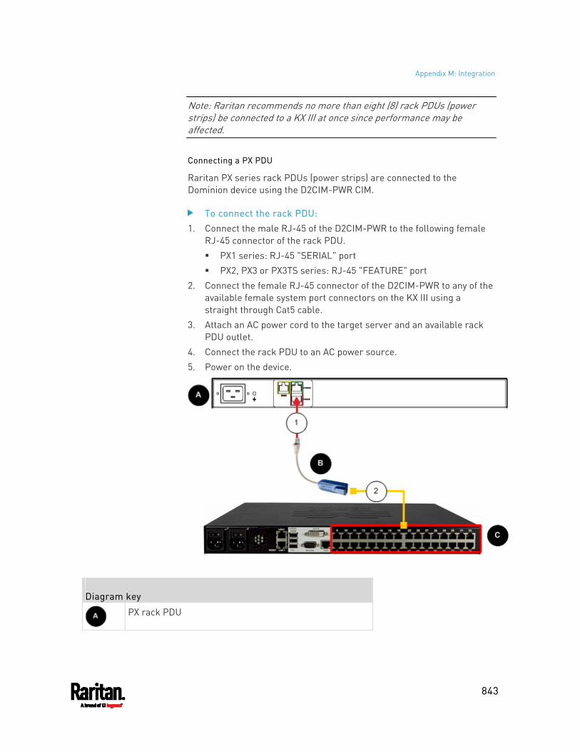
Appendix M: Integration
843
Note: Raritan recommends no more than eight (8) rack PDUs (power strips) be connected to a KX III at once since performance may be affected.
Connecting a PX PDU
Raritan PX series rack PDUs (power strips) are connected to the Dominion device using the D2CIM-PWR CIM.
To connect the rack PDU: 1. Connect the male RJ-45 of the D2CIM-PWR to the following female
RJ-45 connector of the rack PDU. PX1 series: RJ-45 "SERIAL" port PX2, PX3 or PX3TS series: RJ-45 "FEATURE" port
2. Connect the female RJ-45 connector of the D2CIM-PWR to any of the available female system port connectors on the KX III using a straight through Cat5 cable.
3. Attach an AC power cord to the target server and an available rack PDU outlet.
4. Connect the rack PDU to an AC power source. 5. Power on the device.
Diagram key
PX rack PDU
Appendix M: Integration
844
D2CIM-PWR
KX III
D2CIM-PWR to rack PDU connection
D2CIM-PWR to KX III target device port via Cat5 cable
Naming the Rack PDU (Port Page for Power Strips)
Note: PX rack PDUs (power strips) can be named in the PX as well as in the KX III.
Once a Raritan remote rack PDU is connected to the KX III, it will appear on the Port Configuration page. Click on the power port name on that page to access it. The Type and the Name fields are prepopulated.
Note: The (CIM) Type cannot be changed.
The following information is displayed for each outlet on the rack PDU: [Outlet] Number, Name, and Port Association.
Use this page to name the rack PDU and its outlets. Names can be up to 32 alphanumeric characters and can include special characters.
Note: When a rack PDU is associated with a target server (port), the outlet name is replaced by the target server name, even if you assigned another name to the outlet.
To name the rack PDU and outlets:
Note: CommandCenter Secure Gateway does not recognize rack PDU names containing spaces.
1. Enter the Name of the rack PDU (if needed). 2. Change the [Outlet] Name if desired. (Outlet names default to the
outlet #.) 3. Click OK.
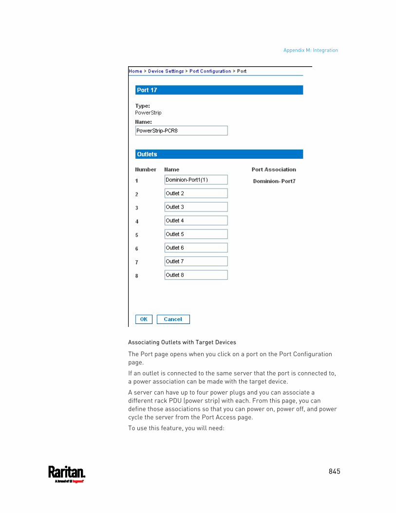
Appendix M: Integration
845
Associating Outlets with Target Devices
The Port page opens when you click on a port on the Port Configuration page.
If an outlet is connected to the same server that the port is connected to, a power association can be made with the target device.
A server can have up to four power plugs and you can associate a different rack PDU (power strip) with each. From this page, you can define those associations so that you can power on, power off, and power cycle the server from the Port Access page.
To use this feature, you will need:
Appendix M: Integration
846
Raritan remote rack PDU(s) Power CIMs (D2CIM-PWR)
Make a Power Association
To make power associations (associate rack PDU outlets to KVM target servers):
Note: When a rack PDU is associated to a target server (port), the outlet name is replaced by the target server name (even if you assigned another name to the outlet).
1. On the Port Configuration page, select the target server you are associating the PDU with.
2. Choose the rack PDU from the Power Strip Name drop-down list. 3. For that rack PDU, choose the outlet from the Outlet Name
drop-down list. 4. Repeat steps 1 and 2 for all desired power associations. 5. Click OK. A confirmation message is displayed.
Turning Outlets On/Off and Cycling Power
To turn an outlet on: 1. Click the Power menu to access the Powerstrip page. 2. From the Powerstrip drop-down, select the PX rack PDU (power
strip) you want to turn on. 3. Click Refresh to view the power controls. 4. Click On next to the outlet you want to power on. 5. Click OK to close the Power On confirmation dialog. The outlet will
be turned on and its state will be displayed as 'on'.
To turn an outlet off: 1. Click Off next to the outlet you want to power off. 2. Click OK on the Power Off dialog. 3. Click OK on the Power Off confirmation dialog. The outlet will be
turned off and its state will be displayed as 'off'.
To cycle the power of an outlet: 1. Click Cycle next to the outlet you want to cycle. The Power Cycle Port
dialog opens. 2. Click OK. The outlet will then cycle (note that this may take a few
seconds).
Appendix M: Integration
847
3. Once the cycling is complete the dialog will open. Click OK to close the dialog.
Dominion KSX II, SX or SX II Configuration
Raritan PX3 support the integration with Raritan's serial access products - Dominion KSX II, Dominion SX and Dominion SX II.
Cables used for connecting the PX3 to different Dominion access products are different.
KSX II - a standard network patch cable (CAT5 or higher) SX - a CSCSPCS cable SX II - a CSCSPCS cable
Note: To only access the CLI of the PX3 via SX / SX II, treat the PX3 as a serial device by connecting SX /SX II to the PDU's serial port instead of the FEATURE port.
For more information on these Dominion serial access product, refer to:
KSX II, SX or SX II User Guide on the Support page (http://www.raritan.com/support/)
KSX II, SX or SX II Online Help on the Product Online Help page (http://www.raritan.com/support/online-help/)
Dominion KSX II
After connecting a Dominion KSX II to the Raritan PDU, you can monitor the PDU and even control its outlets if the PDU is an outlet-switching capable model.
Connecting a Rack PDU
To connect the Raritan PX to the KSX II: 1. Connect one end of a Cat5 cable to the following ports of different
Raritan PX. PX1 series: RJ-45 "SERIAL" port PX2, PX3 or PX3TS series: RJ-45 "FEATURE" port
2. Connect the other end of the Cat5 cable to either the Power Ctrl. 1 or Power Ctrl. 2 ports on the back of the KSX II.
3. Attach an AC power cord to the target server and an available rack PDU outlet.
4. Connect the rack PDU to an AC power source. 5. Power on the KSX II device.
Important: When using CC-SG, the power ports should be inactive
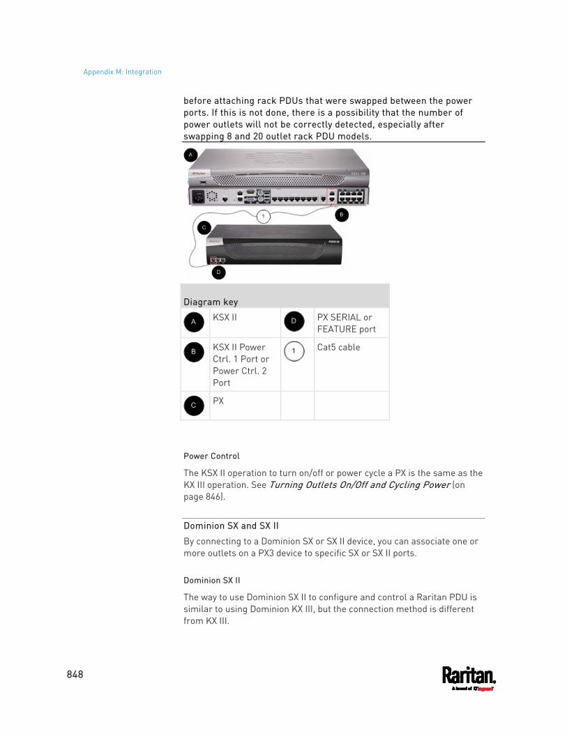
Appendix M: Integration
848
before attaching rack PDUs that were swapped between the power ports. If this is not done, there is a possibility that the number of power outlets will not be correctly detected, especially after swapping 8 and 20 outlet rack PDU models.
Diagram key
KSX II
PX SERIAL or FEATURE port
KSX II Power Ctrl. 1 Port or Power Ctrl. 2 Port
Cat5 cable
PX
Power Control
The KSX II operation to turn on/off or power cycle a PX is the same as the KX III operation. See Turning Outlets On/Off and Cycling Power (on page 846).
Dominion SX and SX II
By connecting to a Dominion SX or SX II device, you can associate one or more outlets on a PX3 device to specific SX or SX II ports.
Dominion SX II
The way to use Dominion SX II to configure and control a Raritan PDU is similar to using Dominion KX III, but the connection method is different from KX III.
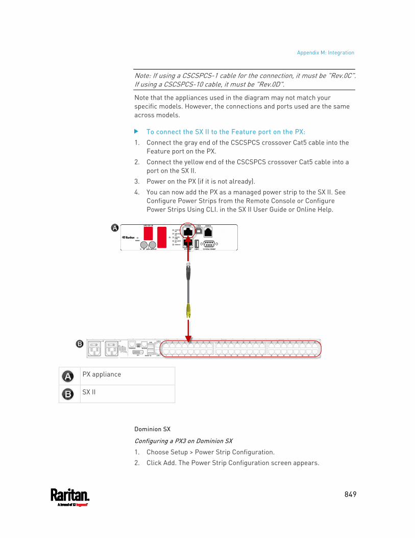
Appendix M: Integration
849
Note: If using a CSCSPCS-1 cable for the connection, it must be "Rev.0C". If using a CSCSPCS-10 cable, it must be "Rev.0D".
Note that the appliances used in the diagram may not match your specific models. However, the connections and ports used are the same across models.
To connect the SX II to the Feature port on the PX: 1. Connect the gray end of the CSCSPCS crossover Cat5 cable into the
Feature port on the PX. 2. Connect the yellow end of the CSCSPCS crossover Cat5 cable into a
port on the SX II. 3. Power on the PX (if it is not already). 4. You can now add the PX as a managed power strip to the SX II. See
Configure Power Strips from the Remote Console or Configure Power Strips Using CLI. in the SX II User Guide or Online Help.
PX appliance
SX II
Dominion SX
Configuring a PX3 on Dominion SX
1. Choose Setup > Power Strip Configuration. 2. Click Add. The Power Strip Configuration screen appears.
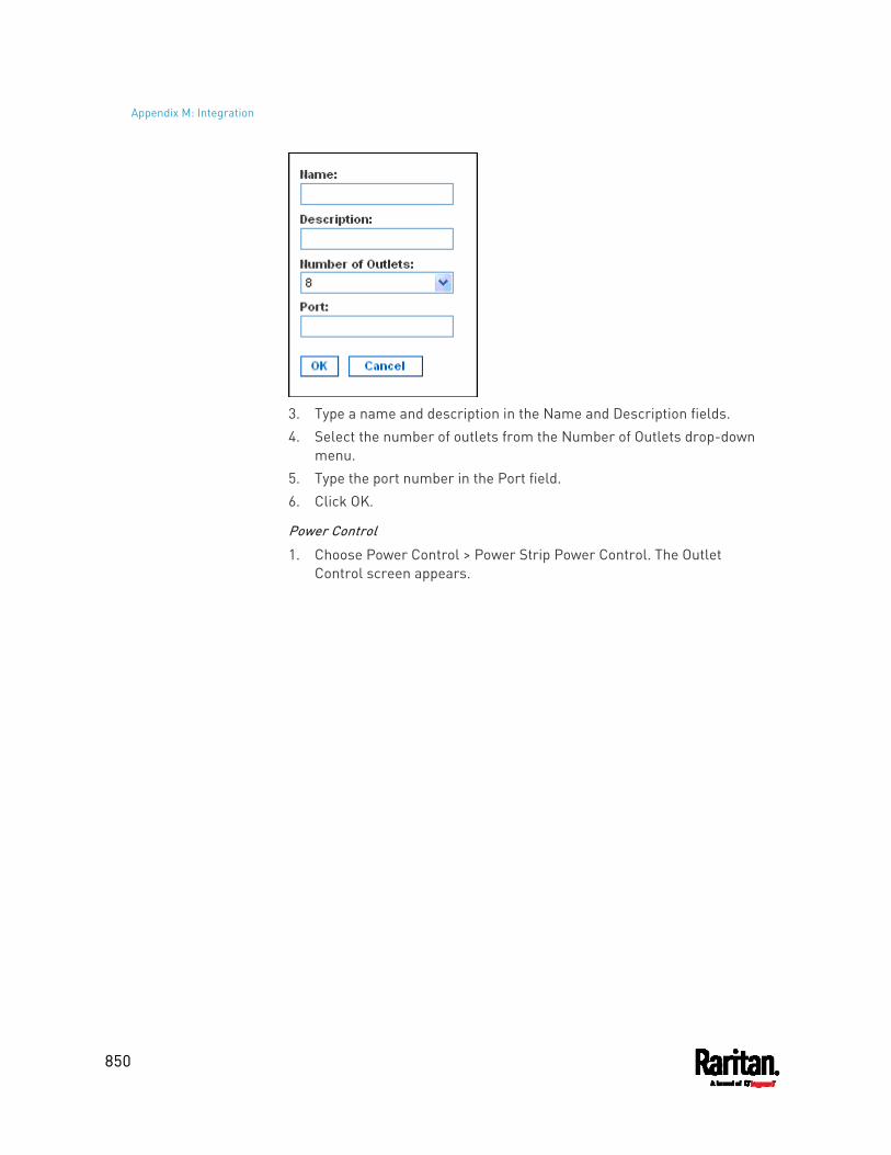
Appendix M: Integration
850
3. Type a name and description in the Name and Description fields. 4. Select the number of outlets from the Number of Outlets drop-down
menu. 5. Type the port number in the Port field. 6. Click OK.
Power Control
1. Choose Power Control > Power Strip Power Control. The Outlet Control screen appears.
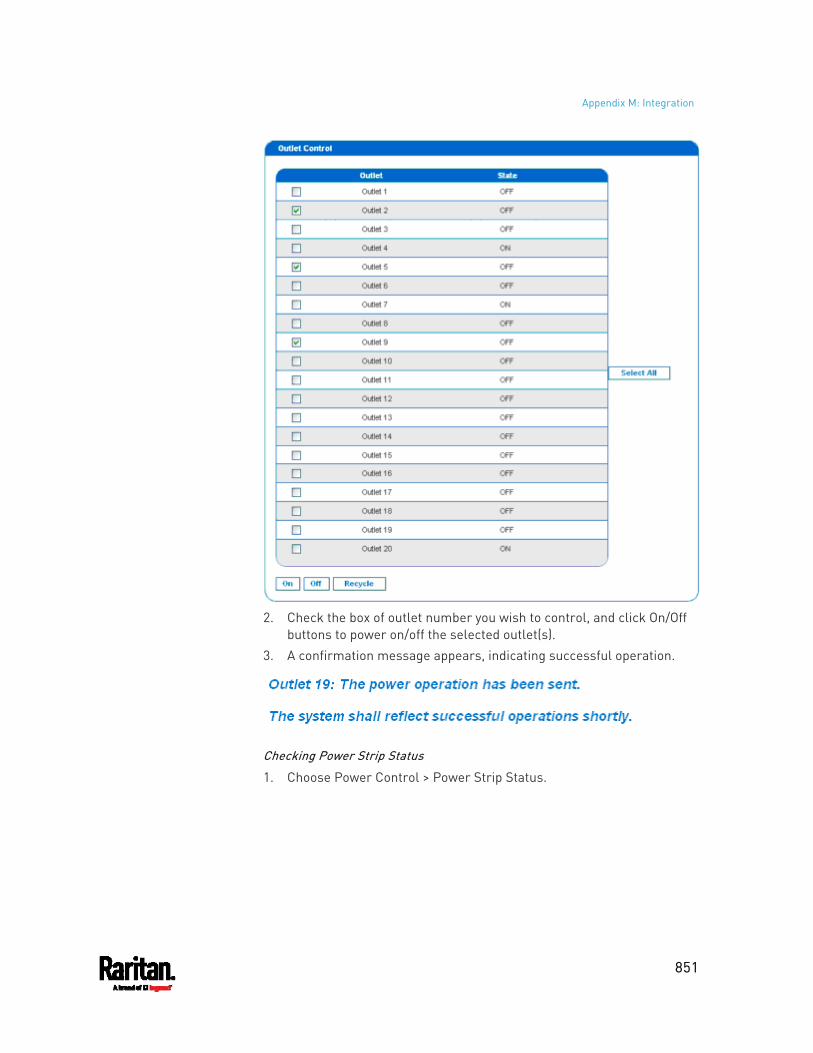
Appendix M: Integration
851
2. Check the box of outlet number you wish to control, and click On/Off
buttons to power on/off the selected outlet(s). 3. A confirmation message appears, indicating successful operation.
Checking Power Strip Status
1. Choose Power Control > Power Strip Status.
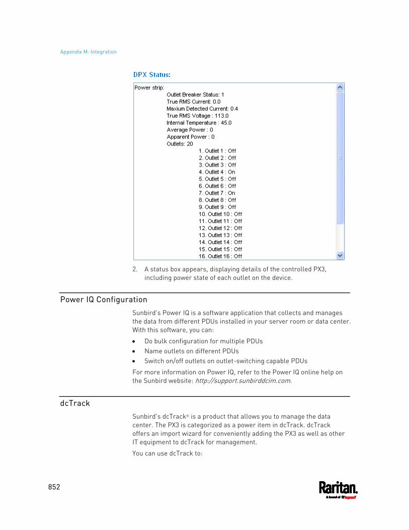
Appendix M: Integration
852
2. A status box appears, displaying details of the controlled PX3,
including power state of each outlet on the device.
Power IQ Configuration
Sunbird's Power IQ is a software application that collects and manages the data from different PDUs installed in your server room or data center. With this software, you can:
Do bulk configuration for multiple PDUs Name outlets on different PDUs Switch on/off outlets on outlet-switching capable PDUs
For more information on Power IQ, refer to the Power IQ online help on the Sunbird website: http://support.sunbirddcim.com.
dcTrack
Sunbird's dcTrack® is a product that allows you to manage the data center. The PX3 is categorized as a power item in dcTrack. dcTrack offers an import wizard for conveniently adding the PX3 as well as other IT equipment to dcTrack for management.
You can use dcTrack to:
Appendix M: Integration
853
Record and manage the data center infrastructure and assets Monitor the electrical consumption of the data center Track environmental factors in the data center, such as temperature
and humidity Optimize the data center growth
For more information on dcTrack, refer to the online help accessible from the dcTrack application, or user documentation available on the Sunbird's website: http://support.sunbirddcim.com.
dcTrack Overview
dcTrack® is a powerful and intelligent data center management and automation application.
It has been designed by data center and IT professionals to provide broad and deep visibility into the data center. It empowers data center managers to plan for growth and change by optimizing their current operations, assets, and infrastructure.
With dcTrack, you can view everything in the data center from servers, blades, virtual servers and applications to data networks, IP addressing space and cabling. dcTrack also allows you to track real-time power consumption and manage raised floor space and rack elevations.
Use dcTrack to build your floor map data center map directly in the application, or import an existing floor map into the dcTrack. Further, dcTrack allows you to import AutoCAD® 2012 (and earlier) objects to build a data center map.
If you currently maintain data center information in spreadsheet format, that data can be imported into dcTrack using the Import wizard.
Isolate potential problems with end-to-end power and data circuits by visually tracing them. This allows you to identify all intermediate circuit points and locate problems.
By using dcTrack's workflow and change management feature, data center managers are better able to enforce best practices across the enterprise and meet ITIL framework guidelines. You can also opt to skip the Change Control workflow process and work in Request Bypass so requests are processed immediately.
dcTrack® can be used as a standalone product or integrated with Power IQ® for power and environmental monitoring.

Appendix M: Integration
854
Asset Management Strips and dcTrack
If any asset strips are connected to the PX3, the PX3 can transmit their information to Sunbird's dcTrack. All you have to do is to add the PX3 to dcTrack, and also add each IT item where an asset tag is attached to dcTrack.
Note: For instructions on connecting asset strips, see Connecting Asset Management Strips (on page 65).
If SNMP is enabled, event information can be transmitted to dcTrack. Specifically, Sunbird's Power IQ detects when an asset tag is connected or disconnected from an asset strip. Power IQ then generates a connection or disconnection event. When dcTrack polls Power IQ, the connection/disconnection events are pulled into dcTrack, and displayed in the dcTrack Web Client.
To poll and display asset management events in dcTrack The PX3 that the asset strip is connected to must exist in dcTrack.
EMX devices are identified as probes in dcTrack; Raritan and Legrand PDUs are identified as sensors.
Each IT item connected to the asset strip via an asset tag must exist in dcTrack. You do not need to manually enter the asset tag IDs for IT items that already exist in dcTrack as long as these items are in the Installed status. Simply, plug the item's asset tag into an asset strip that is connected to the PX3 that exists in dcTrack. dcTrack automatically assigns the asset tag ID to the existing IT item.
Note: If needed, the asset tag number can be overwritten.
For more information on dcTrack as well as how asset strips work with dcTrack, contact Sunbird Professional Services and Support from the http://support.sunbirddcim.com.
855
+
+12V Power Supply Sensor • xxii, 46, 104, 172, 181
1
1U and 2U Port Locations • 90 1U Products • xxi, 2
2
2U Products • xxi, 2
A
A Note about Enabling Thresholds • 498 A Note about Firmware Upgrade Time • 450 A Note about Infinite Loop • 404 A Note about Untriggered Rules • 405 About the Interface • 500 Action Group • 367, 370 Actuator Configuration Commands • 642, 663 Actuator Control Operations • 686 Actuator Information • 517 Adding a Firewall Rule • 585 Adding a Monitored Device • 664 Adding a Radius Server • 639 Adding a Role-Based Access Control Rule •
598 Adding an LDAP Server • 632, 638 Adding Attributes to the Class • 827 Adding LDAP/LDAPS Servers • 329, 331, 335 Adding Radius Servers • 329, 334, 335, 832 Adding, Removing or Swapping Cascaded
Devices • 305 Additional PX3 Information • 868 AD-Related Configuration • 833, 851, 864 Alarm • 367, 369 Alerts • xxii, 98, 99, 135, 136 Alerts Notice in a Yellow or Red Screen • xxii,
94, 133, 171 All Privileges • 619, 625, 629 Altitude Correction Factors • 234, 549, 883 APIPA and Link-Local Addressing • 2, 31, 147,
297, 315
Applicable Models • xviii, xxi Assertion Timeout Example for Temperature
Sensors • 877 Asset Management Commands • 670 Asset Management Log • xxiii, 409, 415 Asset Management Strips and dcTrack • 920 Asset Management Tag List • xxiii, 409, 412 Asset Strip • 124, 126, 253, 255 Asset Strip Automatic Firmware Upgrade •
263 Asset Strip Information • 813 Asset Strip Management • 670 Asset Strip Settings • 532 Assets • 98, 123 Associating Outlets with Target Devices • 911 Authentication Commands • 630 Authentication Settings • 529, 632, 636 Automatic and Manual Modes • xxi, 94, 98, 424 Automatically Completing a Command • 504,
505, 693 Available Actions • xxiii, 83, 311, 344, 366, 370,
376, 386, 398, 467, 490 Available Data of the Outlets Overview Page •
188, 191, 196, 197
B
Backup and Restore of Device Settings • 437, 451, 459, 735
Backup and Restore via SCP • 460, 697 Beeper • 143, 176 Before You Begin • 3 Blade Extension Strip Settings • 534 Browsing through the Online Help • 153, 905 Built-in Rules and Rule Configuration • 344,
345, 398 Bulk Configuration • xxiii, 33, 437, 451, 459,
696, 735 Bulk Configuration for Outlet Thresholds • 188,
192, 203 Bulk Configuration Methods • xxi, 25, 33 Bulk Configuration or Firmware Upgrade via
DHCP/TFTP • xxiv, 33, 448, 452, 457, 730, 746
Index
Index
856
Bulk Configuration Restrictions • 451, 453 Bulk Configuration via SCP • xxiv, 452, 457,
696, 704 Bulk Configuration/Upgrade Procedure • xxiv,
747, 748 Button-Type Locking Outlets • 20
C
Calendar • 340, 342 Canceling the Power-On Process • 685 Card Readers • xxiii, 481, 486, 487 Cascading All Devices via USB • xxi, 37, 42, 90 Cascading Multiple PX3 Devices for Sharing
Ethernet Connectivity • xxi, 22, 24, 34, 286, 297, 440
Cascading Troubleshooting • 36, 305, 887 Change Load Shedding State • 367, 370 Changing a User's Password • 613 Changing an Outlet's Default State • 605 Changing HTTP(S) Settings • xxiii, 282, 307,
308, 316 Changing Measurement Units • 619, 622 Changing Modbus Settings • 283, 307, 314 Changing SSH Settings • 272, 283, 307, 313 Changing Storage Settings • 373, 467, 469, 470,
473, 476 Changing Telnet Settings • 283, 307, 314, 500 Changing the Inlet Name • 610 Changing the LAN Duplex Mode • xxiv, 563 Changing the LAN Interface Speed • xxiv, 562 Changing the Modbus Configuration • 576 Changing the Modbus Port • 577 Changing the Outlet Name • 604 Changing the Overcurrent Protector Name •
611 Changing the PDU Name • 543 Changing the Role(s) • 619 Changing the Sensor Description • 645 Changing the Sensor Name • 642 Changing the SSH Configuration • 573 Changing the SSH Port • 573 Changing the Telnet Configuration • 572 Changing the Telnet Port • 573 Changing the UDP Port • 669 Changing Your Own Password • 621 Changing Your Password • 149, 270, 272
Checking Lua Scripts States • 430, 431, 432 Checking Power Strip Status • 917 Checking RCM State and Current • 783, 785 Checking RCM States and Current • xxv, 790 Checking the Accessibility of NTP Servers •
583 Checking the Branch Circuit Rating • 4 Circuit Breaker Orientation Limitation • 5, 6, 8,
9, 11 Circuit Breakers • 138 Clearing Event Log • 541 Clearing Information • 541 Clearing WLAN Log • 542 CLI Operations for RCM • 794 Closing a Local Connection • 503 Combining Regular Asset Strips • 72 Command History • 538 Commands for Environmental Sensors • 659 Commands for Inlet Pole Sensors • 655, 797 Commands for Inlet Sensors • 653, 797 Commands for Outlet Group Sensors • xxiv,
651 Commands for Outlet Sensors • 649 Commands for Overcurrent Protector Sensors
• 658 Common Network Settings • 284, 286 Compliance with IEC 62020 • 781, 796 config.txt • xxiv, 33, 700, 703, 732, 734, 738,
769, 772, 773 Configuration Files • 730, 732, 747, 769 Configuration or Firmware Upgrade with a
USB Drive • 34, 452, 457, 730, 743, 746 Configuring a Multi-Inlet Model • 182, 185 Configuring a PX3 on Dominion SX • 915 Configuring Data Push Settings • xxiii, 283,
373, 407 Configuring DNS Parameters • 560 Configuring Environmental Sensors' Default
Thresholds • 647 Configuring IPv4 Parameters • 551 Configuring IPv6 Parameters • 556 Configuring Login Settings • 283, 316, 336 Configuring Network Services • 307, 501 Configuring Network Settings • xxii, 3, 23, 38,
42, 282, 284, 292, 892 Configuring NTP Server Settings • 497
Index
857
Configuring Password Policy • 283, 316, 337 Configuring Rack PDU Targets • 908 Configuring Security Settings • 316 Configuring SMTP Settings • 283, 307, 311,
375, 380 Configuring SNMP Settings • 272, 282, 307,
309, 366, 489 Configuring the Cascading Mode • xxiv, 569 Configuring the PX3 • 25 Configuring the PX3 Device and Network • 542 Configuring the Serial Port • 83, 84, 283, 426,
502 Configuring Webcams and Viewing Live
Images • 82, 467, 468, 472, 473, 478 Connecting a DPX2 Sensor Package to DX2, DX
or DPX3 • 52, 54, 55, 58, 71 Connecting a GSM Modem • xxi, 83, 378 Connecting a Logitech Webcam • xxi, 82, 466 Connecting a Mobile Device to PX3 • 25, 26, 90 Connecting a PX PDU • 908 Connecting a PX3 Locking Line Cord • 14, 87 Connecting a Rack PDU • 913 Connecting a Schroff LHX/SHX Heat
Exchanger • 85, 264 Connecting an Analog Modem • xxi, 84, 502 Connecting an External Beeper • 84, 263 Connecting Asset Management Strips • 71,
255, 407, 920 Connecting Blade Extension Strips • 76 Connecting Composite Asset Strips
(AMS-Mx-Z) • 79 Connecting External Equipment (Optional) • 50,
91 Connecting Raritan Environmental Sensor
Packages • 49, 50, 230 Connecting Regular Asset Strips to PX3 • 74,
80 Connecting the PDU to a Power Source • 21 Connecting the PX3 to a Computer • 3, 25, 31,
297, 775, 776, 887 Connecting the PX3 to Your Network • xxi, 22,
25, 284 Connection Port Functions • 24, 90 Connection Ports • 89 Control Buttons • xxi, 95, 801
Copying an Existing Server's Settings • 632, 636
Creating a CSR • 323, 324, 325 Creating a New Attribute • 826 Creating a Role • 625 Creating a Self-Signed Certificate • 323, 326 Creating a User Profile • 612 Creating an Outlet Group • xxii, xxiv, 114, 207,
208, 607 Creating Configuration Files via Mass
Deployment Utility • 732, 742, 743 Creating IP Access Control Rules • 283, 316,
317, 320 Creating Role Based Access Control Rules •
283, 316, 321, 323 Creating Roles • 149, 270, 274, 277, 832 Creating Users • 146, 149, 270, 271, 275, 278,
281, 313, 329, 489 Curl Upload Return Codes • xxv, 772, 774 Customizing Bulk Configuration Profiles • 451,
454 Customizing the Date and Time • 581
D
Daisy-Chain Limitations of Composite Asset Strips • xxi, 80, 81
Dashboard • xxii, 154, 159, 181, 223, 369, 462, 788
Dashboard - Alarms • xxii, 160, 170, 366, 717 Dashboard - Alerted Sensors • 99, 160, 165,
717 Dashboard - Inlet History • 160, 167, 182 Dashboard - Inlet I1 • 160, 161, 182, 717 Dashboard - OCP • 160, 163 Dashboard Page • 716 Data Encryption in 'config.txt' • 738, 740, 743 Data for BTU Calculation • xxv, 885 Data Push Format • xxiii, 407, 409 Date and Time Settings • 514 dcTrack • 918 dcTrack Overview • 919 Deassertion Hysteresis Example for
Temperature Sensors • 880 Default Log Messages • xxiii, 46, 338, 345, 351,
372, 375 Default Measurement Units • 514
Index
858
Default Voltage and Current Thresholds • 183, 192, 203, 222, 225, 881
Degaussing RCM Type B Sensors • 798 Deleting a Firewall Rule • 588 Deleting a Monitored Device • 665 Deleting a Role • 630 Deleting a Role-Based Access Control Rule •
601 Deleting a User Profile • 621 Deleting an Outlet Group • xxii, 217 Derating a Raritan Product • 708 Detailed Information on Outlet Pages • 199,
205 Determining the Authentication Method • 630 Determining the SSH Authentication Method •
574 Determining the Time Setup Method • 579,
581 Device Configuration/Upgrade Procedure •
xxiv, 730 Device Info • xxii, 3, 24, 25, 98, 127, 297 Device Information • 436, 438, 478 Device Settings • 156, 282 devices.csv • 33, 703, 732, 734, 739, 741, 773 Device-Specific Settings • 451, 897 DHCP IPv4 Configuration in Linux • 747, 765 DHCP IPv4 Configuration in Windows • 747,
748 DHCP IPv6 Configuration in Linux • 747, 767 DHCP IPv6 Configuration in Windows • 747,
758 Diagnostic Commands • 690 Different CLI Modes and Prompts • 501, 502,
503, 505, 541, 542, 543, 583, 680, 682, 686, 690
Disabling or Enabling Front Panel RCM Self-Test • 425, 787, 791, 818
Disconnecting a PX3 Locking Line Cord • 15 Dominion KSX II • 912 Dominion KSX II, SX or SX II Configuration •
269, 912 Dominion KX II / III Configuration • 269, 907 Dominion SX • 915 Dominion SX and SX II • 914 Dominion SX II • 914 Door Handle Status and Control • xxiii, 485
Dot-Matrix LCD Display • xxi, 92 Download via Curl • xxv, 769, 770 Download via Web Browsers • xxiv, 769 Downloading Diagnostic Data via SCP • 699 Downloading Diagnostic Information • 437,
461 Downloading Raw Configuration • xxiv, 769 Downloading SNMP MIB • 311, 489, 494, 793 DPX Sensor Packages • 48, 50, 59 DPX2 Sensor Packages • 48, 50, 56 DPX3 Sensor Packages • 48, 50, 54 Dual Ethernet Connection • xxi, 22, 24 DX Sensor Packages • 48, 50, 53, 384 DX2 Sensor Packages • 48, 50, 51, 384
E
EAP CA Certificate Example • 565, 567 Editing or Deleting a Rule/Action • 366, 398,
424 Editing or Deleting IP Access Control Rules •
320 Editing or Deleting Ping Monitoring Settings •
422 Editing or Deleting Role Based Access Control
Rules • 322 Editing or Deleting Roles • 212, 279 Editing or Deleting Users • 149, 275, 278, 280 Editing rciusergroup Attributes for User
Members • 829 Enabling and Configuring SNMP • 400, 401,
406, 489 Enabling or Disabling a User Profile • 615 Enabling or Disabling an Inlet (for Multi-Inlet
PDUs) • 610 Enabling or Disabling Data Logging • 548 Enabling or Disabling EnergyWise • 668 Enabling or Disabling Front Panel Actuator
Control • 602 Enabling or Disabling Front Panel Outlet
Switching • 602 Enabling or Disabling Load Shedding • 681 Enabling or Disabling Modbus • 576 Enabling or Disabling Peripheral Device Auto
Management • 550 Enabling or Disabling Service Advertising •
577
Index
859
Enabling or Disabling SNMP v1/v2c • 574 Enabling or Disabling SNMP v3 • 575 Enabling or Disabling SSH • 573 Enabling or Disabling Strong Passwords • 594 Enabling or Disabling Telnet • 572 Enabling or Disabling the LAN Interface • xxiv,
561 Enabling or Disabling the Read-Only Mode •
577 Enabling or Disabling the Restricted Service
Agreement • 589 Enabling Service Advertising • 283, 308, 315,
577 Enabling the Restricted Service Agreement •
147, 283, 316, 338 EnergyWise Configuration Commands • 668 EnergyWise Settings • 532 Entering Configuration Mode • 503, 542, 567,
613, 621, 796 Entering Diagnostic Mode • 503, 690, 890 Environmental Sensor Configuration
Commands • 642 Environmental Sensor Default Thresholds •
527 Environmental Sensor Information • 515, 810 Environmental Sensor Package Information •
516 Environmental Sensor Threshold Information
• 526 Equipment Setup Worksheet • 4, 726 Ethernet Interface Settings • xxii, 24, 131, 285,
287 Event Log • 535 Event Rules and Actions • 46, 84, 143, 170, 176,
182, 192, 222, 246, 267, 283, 309, 311, 344, 369, 407, 416, 430, 721
Example • 581, 591, 613, 621, 678, 681 Ping Monitoring and SNMP Notifications •
416, 422 Example - Actuator Naming • 664 Example - Creating a Role • 630 Example - Default Upper Thresholds for
Temperature • 649 Example - Inlet Naming • 611 Example - OCP Naming • 611 Example - Outlet Naming • 606
Example - Ping Command • 693 Example - Power Cycling Specific Outlets •
685 Example - Server Settings Changed • 667 Example - Setting Up EnergyWise • 670 Example - Turning On a Specific Actuator •
687 Example 1 • 404 Example 1 - Asset Strip LED Colors for
Disconnected Tags • 676 Example 1 - Basic Security Information • 539 Example 1 - Combination of IP, Subnet Mask
and Gateway Parameters • 679 Example 1 - Creating a User Profile • 624 Example 1 - Environmental Sensor Naming •
646 Example 1 - IPv4 Firewall Control
Configuration • 603 Example 1 - Networking Mode • 578 Example 1 - PDU Naming • 551 Example 1 - Time Setup Method • 582 Example 1 - Upper Critical Threshold for a
Temperature Sensor • 661 Example 2 • 405 Example 2 - Adding an IPv4 Firewall Rule •
603 Example 2 - Combination of Upper Critical and
Upper Warning Settings • 679 Example 2 - Enabling Both IP Protocols • 578 Example 2 - In-Depth Security Information •
540 Example 2 - Modifying a User's Roles • 624 Example 2 - Outlet Sequence • 551 Example 2 - Primary NTP Server • 582 Example 2 - Rack Unit Naming • 677 Example 2 - Sensor Threshold Selection • 646 Example 2 - Warning Thresholds for Inlet
Sensors • 661 Example 3 • 405 Example 3 - Basic PDU Information • 540 Example 3 - Combination of SSID and PSK
Parameters • 680 Example 3 - Default Measurement Units • 624 Example 3 - Outlet Sequence Delay • 551 Example 3 - Upper Thresholds for Overcurrent
Protector Sensors • 662
Index
860
Example 3 - User Blocking • 603 Example 3 - Wireless Authentication Method •
578 Example 4 - Adding an IPv4 Role-based
Access Control Rule • 604 Example 4 - Combination of Upper Critical,
Upper Warning and Lower Warning Settings • 680
Example 4 - In-Depth PDU Information • 541 Example 4 - Non-Critical Outlets • 551 Example 4 - Static IPv4 Configuration • 578 Examples • 539, 550, 578, 582, 602, 623, 646,
661, 676 Existing Roles • 531 Existing User Profiles • 514, 530 Expansion RJ-45 Port Pinouts • 725 Extended Cascading with PX3 Devices • xxi, 40,
92 External Beeper • 253, 263, 367, 371
F
Feature Port • 155, 252, 255, 263, 265, 269 Feature RJ-45 Port Pinouts • 724 Filling Out the Equipment Setup Worksheet •
4 Finding the Sensor's Serial Number • 232, 241 Firewall Control • 583 Firmware Update via SCP • 448, 695 Firmware Upgrade via USB • xxiv, 448, 731,
744 Flexible Cord Installation Instructions • 706 Flexible Cord Selection • 707 Forcing a Password Change • 615 Forcing the Device Detection Mode • 678 FreeRADIUS Standard Attribute Illustration •
832, 850 FreeRADIUS VSA Illustration • 851, 863 From LDAP/LDAPS • 825 From Microsoft Active Directory • 825 Front Panel Operations for RCM • 98, 789, 816 Front Panel Settings • xxiii, 94, 105, 109, 111,
114, 117, 237, 283, 424, 808 Full Disaster Recovery • xxiii, 450 Fuse • 140 Fuse Replacement on 1U Models • 141 Fuse Replacement on Zero U Models • 140
fwupdate.cfg • xxiv, 730, 732, 733, 738, 741, 744, 747
G
Gathering LDAP/Radius Information • 329, 330 Group's Power Control • xxii, 117
H
Hardware Issue Detection • xxiii, 161, 437, 462, 538
How Long a Link Remains Accessible • 471, 473
How the Automatic Management Function Works • 234, 244, 550
I
Identifying Cascaded Devices • 439, 440 Identifying Snapshots Folders on Remote
Servers • 470, 477, 478 Identifying the Sensor Port • 51 Identifying the Sensor Position and Channel •
232, 242 Idle Timeout • 593 If Switchable Outlet Groups are Limited • xxii,
212 Illustration - GMAIL SMTP Certificate Chain •
898, 902 Illustrations of Adding LDAP Servers • 634,
635 Individual OCP Pages • 223 Individual Outlet Pages • xxii, 173, 174, 175,
177, 178, 188, 190, 195, 199, 206, 722 Individual Sensor/Actuator Pages • 122, 165,
231, 234, 235, 236, 246, 252 Initial Installation and Configuration • 21 Initial Network Configuration via CLI • xxv, 25,
32, 775, 776, 892 Initialization Delay Use Cases • 173, 178 Inlet • xxii, 87, 98, 106, 154, 161, 163, 175, 182,
185 Inlet Configuration Commands • 609 Inlet Information • 512, 804 Inlet Pole Sensor Threshold Information • 523,
795 Inlet Sensor Threshold Information • 521, 795
Index
861
Inlets/Outlets Page • 721 In-Line Monitor Unused Channels • 709 In-Line Monitors • 705 In-Line Monitor's Web Interface • 715 Inrush Current and Inrush Guard Delay • 174,
178 Installing a CA-Signed Certificate • 323, 325 Installing Cable Retention Clips on Outlets
(Optional) • 17 Installing Cable Retention Clips on the Inlet
(Optional) • 16 Installing or Downloading Existing Certificate
and Key • 323, 327 Installing the USB-to-Serial Driver (Optional) •
32, 891 Integration • 907 Interface Names • 293, 296 Internal Beeper • 367, 371 Internal Beeper State • 172, 175, 785 Introduction • xxi, 1 Introduction to Asset Tags • 74 Introduction to PDU Components • 86 IP Configuration • xxiii, 506, 507 IPv4 Address • 806 IPv4-Only or IPv6-Only Configuration • xxiii,
506, 507
K
Keys that Cannot Be Uploaded • xxiv, 700, 704, 769
L
Layout • 496 LCD Message for RCM Critical State • xxv, 789 LDAP Configuration Illustration • 329, 819 LDAP Settings • 631 Load Shedding Configuration Commands •
680 Load Shedding Mode • 189, 191, 194, 196, 201,
370, 547 Load Shedding Settings • 531 Locking Outlets and Cords • 17, 18 Log an Event Message • 367, 372 Log Rows • xxiii, 409, 411 Logging in to CLI • 500, 743, 776
Logging out of CLI • 694 Login • xxii, 25, 31, 147, 297, 890 Login Limitation • 592 Login, Logout and Password Change • 146 Logout • 150 Lowercase Character Requirement • 595 Lua Scripts • 283, 382, 427
M
MAC Address • 807 Main Menu • xxii, 94, 97, 790, 791 Maintenance • xxiii, 156, 436 Make a Power Association • 911 Making a Power-Sharing Connection • xxi, 46 Managed vs Unmanaged Sensors/Actuators •
230, 238, 239 Managing an Outlet Group • xxiv, 607 Managing External Authentication Settings •
329, 333, 335 Managing Firewall Rules • 585 Managing One Sensor or Actuator • 232, 233,
244 Managing Role-Based Access Control Rules •
598 Manually Changing the Zero U LCD
Orientation • xxii, 93, 132 Manually Starting or Stopping a Script • 428,
429, 430 Maximum Ambient Operating Temperature •
xxiv, 4, 723 Maximum Password History • 596 Maximum Password Length • 594 Menu • xxii, 152, 154, 172, 182, 187, 207, 221,
230, 253, 255, 263, 264, 269, 270, 282, 429, 432, 433, 436, 468, 471, 482, 487, 783
Minimum Password Length • 594 Miscellaneous • xxiii, 85, 119, 253, 254, 264,
283, 374, 383, 434, 439, 494 Mixing Diverse Sensor Types • 64, 66 Modifying a Firewall Rule • 587 Modifying a Monitored Device's Settings • 665 Modifying a Role • 628 Modifying a Role-Based Access Control Rule •
599 Modifying a User Profile • 612 Modifying a User's Personal Data • 614
Index
862
Modifying an Existing LDAP Server • 636 Modifying an Existing Radius Server • 640 Modifying an Outlet Group • xxii, 208, 215 Modifying Firewall Control Parameters • 583 Modifying or Deleting a Script • 428, 433 Modifying or Removing Bulk Profiles • 457 Modifying Role-Based Access Control
Parameters • 597 Modifying SNMPv3 Settings • 616 Monitoring Server Accessibility • xxiii, 283, 372,
416, 422 Mounting 1U or 2U Models • 12 Mounting Zero U Models Using Button Mount
• 8 Mounting Zero U Models Using Claw-Foot
Brackets • 9 Mounting Zero U Models Using L-Brackets • 6 Mounting Zero U Models Using Two Rear
Buttons • 11 Multi-Command Syntax • 585, 592, 593, 594,
598, 607, 612, 614, 616, 619, 622, 647, 649, 651, 653, 655, 658, 659, 663, 665, 679
Muting the Internal Beeper • xxii, 102, 105
N
Naming a Rack Unit • 674 Naming an Asset Strip • 670 Naming the Rack PDU (Port Page for Power
Strips) • 909 Network Configuration • 505 Network Configuration Commands • 551 Network Diagnostics • 437, 460 Network Interface Settings • xxiii, 508 Network Service Settings • 509 Network Troubleshooting • 460, 690 NPS Standard Attribute Illustration • 832 NPS VSA Illustration • 851 Numeric Character Requirement • 595
O
OCPs • 98, 108, 155, 164, 221, 223, 225, 229 Off and Lock Icons for Outlets • xxii, 197, 198 Old Generations of PX3 Models • xxv, 93, 450,
799
Operating the Dot-Matrix LCD Display • xxi, 94, 96, 97, 99, 120, 138, 799
Operating the LCD Display • 802 Optional Parameters • 632, 633 Options for Outlet State on Startup • 173, 177,
200 Outlet Configuration Commands • 604 Outlet Group Configuration Commands • xxiv,
606 Outlet Group Information • xxiii, 511 Outlet Group Power Control • xxii, 208, 209 Outlet Group Threshold Information • xxiv, 520 Outlet Groups • xxii, 98, 114, 155, 174, 207, 213,
215, 372, 520, 652 Outlet Information • 510, 802 Outlet Pole Sensor Threshold Information •
519 Outlet Sensor Threshold Information • 518 Outlet Switching • 808 Outlets • 88, 98, 109, 154, 187, 191, 196, 197,
199, 384 Overcurrent Protector Configuration
Commands • 611 Overcurrent Protector Information • 229, 513,
805 Overcurrent Protector Sensor Threshold
Information • 525 Overview • 705 Overview of the Cascading Modes • 297, 300 Overview of the LCD Display • 800, 802
P
Package Contents • 1, 3 Panel Components • 86 Password Aging • 592 Password Aging Interval • 593 PDU • xxii, 98, 102, 143, 152, 154, 172, 177, 178,
179, 181, 183, 190, 201, 202, 206, 214, 230, 244, 248, 251, 547
PDU Configuration • 176, 510 PDU Configuration Commands • 543 Performing Bulk Configuration • xxiii, 451, 456 Peripherals • xxii, 48, 51, 53, 98, 119, 155, 230,
235, 237, 239, 241, 244, 246, 247, 251, 252, 403, 425, 486
Index
863
Placeholders for Custom Messages • xxiii, 375, 378, 379, 394
Plug Selection • 707 Port Forwarding Examples • 148, 299, 302,
303 Port Number Syntax • 298, 300, 301, 303, 888 Possible OCP-Tripped Root Cause • 223, 228,
513 Possible Root Causes • 887 Power CIM • 253, 269 Power Control • 111, 200, 425, 914, 916 Power Control Operations • 682 Power Cycling the Outlet(s) • 684 Power IQ Configuration • 917 Powering On/Off/Cycle Outlet Groups • xxiv,
609 Power-Off Period Options for Individual
Outlets • 201, 206 Power-Sharing Configurations and
Restrictions • xxi, 45, 46, 47 Power-Sharing Restrictions and Connection •
xxi, 45, 92, 181, 779, 780, 783, 785 Preparing the Installation Site • 4 Product Models • 1 Push Out Sensor Readings • 367, 373 PX3 Latching Relay Behavior • 173, 177, 544,
545, 546, 547 PX3 Models with Residual Current Monitoring
• 176, 424, 778, 816 PX3 'Phase I' Front Panel Display • xxv, 800 PX3 'Phase II' Front Panel Display • xxv, 799 PX3-3000 Series • 88 PX3-4000 Series • 88 PX3-5000 Series • xxi, 88
Q
Querying Available Parameters for a Command • 503, 504
Querying DNS Servers • 691 Quick Access to a Specific Page • 147, 157 Quitting Configuration Mode • 543, 591 Quitting Diagnostic Mode • 690
R
Rack Unit Configuration • 673
Rack Unit Settings of an Asset Strip • 533 Rackmount Safety Guidelines • 5 Rackmount, Inlet and Outlet Connections • 5 Rack-Mounting the PDU • 5 RADIUS Configuration Illustration • 329, 832 Radius Settings • 639 Raritan Training Website • 886 Raw Configuration Upload and Download •
xxiv, 452, 457, 740, 746, 769 RCM Critical State Alarm • 785 RCM Current Sensor • 522, 524, 655, 657, 779,
788 RCM Information • 789, 816 RCM Residual Current and State Objects • 794 RCM Self-Test • 782 RCM SNMP Operations • 793 RCM State Sensor • 780, 784 RCM Trap • 793 Rebooting the PX3 • 437, 463 Receptacle Selection • 707 Record Snapshots to Webcam Storage • 367,
373 Reliability Data • 538 Reliability Error Log • 538 Reliability Hardware Failures • xxiv, 538 Remembering User Names and Passwords •
150 Removing an Existing LDAP Server • 639 Removing an Existing Radius Server • 642 Replaceable Controller • 86, 144 Request LHX/SHX Maximum Cooling • 367,
374 Reserving IP Addresses in DHCP Servers • xxv,
869, 870, 871 Reserving IP in Linux • xxv, 871 Reserving IP in Windows • xxv, 870 Reset Button • xxii, 137 Resetting a Group's Active Energy • xxii, 208,
213 Resetting Active Energy Readings • xxiv, 688 Resetting All Settings to Factory Defaults •
437, 464, 775 Resetting the Button-Type Circuit Breaker •
138 Resetting the Handle-Type Circuit Breaker •
139
Index
864
Resetting the PX3 • 688 Resetting to Factory Defaults • 137, 465, 689,
775 Restarting the PDU • 688 Restricted Service Agreement • 589 Restrictions of Port-Forwarding Connections •
40, 43, 889 Retrieving Energy Usage • 498 Retrieving Previous Commands • 504, 505,
693 Retrieving Software Packages Information •
437, 465 Returning User Group Information • 825 RJ45-to-DB9 Cable Requirements for
Computer Connections • xxi, 32, 91, 869 RJ45-to-DB9 Cable Requirements for Modem
Connections • xxv, 33, 83, 84, 91, 868 Role Configuration Commands • 625 Role of a DNS Server • 821, 886 Role-Based Access Control • 596 Running RCM Self-Test • xxv, 790, 791, 794,
798
S
Safety Guidelines • ii Safety Instructions • iii, 4, 705 Sample Environmental-Sensor-Level Event
Rule • 197, 402 Sample Event Rules • 347, 398 Sample Inlet-Level Event Rule • 401 Sample Outlet-Level Event Rule • 399 Sample PDU-Level Event Rule • 398 Saving User Credentials for PDView's
Automatic Login • xxi, 28, 29 Scheduling an Action • 345, 373, 386, 392, 787 Scheduling RCM Self-Test • 787 Schroff LHX/SHX • 253, 264 SecureLock™ Outlets and Cords • 19 Security Configuration Commands • 583 Security Settings • 528 Send an SNMP Notification • 311, 368, 380 Send Email • xxiii, 351, 368, 374, 388, 394 Send Sensor Report • 281, 368, 376, 391 Send Sensor Report Example • 376, 388 Send SMS Message • xxiii, 368, 378, 394 Send Snapshots via Email • 368, 379
Sending Links to Snapshots or Videos • 467, 469, 471
Sensor Descriptors for Inlet Active Power • xxiii, 409, 410
Sensor Log • xxiii, 409 Sensor RJ-45 Port Pinouts • 723 Sensor Threshold Configuration Commands •
xxiv, 649 Sensor Threshold Settings • 180, 184, 193, 204,
217, 223, 226, 236, 237, 247, 497, 789, 873 Sensor/Actuator Location Example • 248, 251,
252 Sensor/Actuator States • 100, 120, 166, 231,
232, 239, 240 Serial Port Configuration Commands • 677 Serial Port Settings • 532 Serial RS-232 • 723, 818 Server Reachability Configuration Commands
• 664 Server Reachability Information • 536 Server Reachability Information for a Specific
Server • 537 Server Status Checking or Power Control •
xxiii, 420 Setting an LED Color for a Rack Unit • 675 Setting an LED Mode for a Rack Unit • 675,
676 Setting an Outlet's Cycling Power-Off Period •
606 Setting Data Logging • 283, 406, 408, 548 Setting Data Logging Measurements Per Entry
• 548 Setting Default Measurement Units • 234, 270,
280, 281, 619, 622 Setting EAP Parameters • 565 Setting Front Panel RCM Self-Test • 797 Setting IPv4 Static Routes • xxiv, 555 Setting IPv6 Static Routes • xxiv, 559 Setting LAN Interface Parameters • 561 Setting LED Colors for Connected Tags • 673,
674, 675 Setting LED Colors for Disconnected Tags •
673, 674, 675 Setting Network Service Parameters • 570 Setting Non-Critical Outlets • 188, 194, 196 Setting NTP Parameters • 580, 583
Index
865
Setting Outlet Power-On Sequence and Delay • 188, 193
Setting RCM Current Thresholds • 780, 784, 786, 796
Setting RCM DC Current Thresholds • 784, 786, 788
Setting RCM Thresholds • 794 Setting the Alarmed to Normal Delay for
DX-PIR • 646 Setting the Authentication Method • 564 Setting the Automatic Daylight Savings Time •
582 Setting the Baud Rates • 677 Setting the BSSID • 568 Setting the Cascading Mode • xxiii, 2, 24, 35,
37, 38, 40, 42, 129, 284, 285, 286, 288, 297, 300, 305, 440, 441
Setting the Date and Time • xxiii, 283, 340, 478, 497
Setting the HTTP Port • 571 Setting the HTTPS Port • 572 Setting the Inrush Guard Delay Time • 546 Setting the IPv4 Address • xxiv, 554 Setting the IPv4 Configuration Mode • xxiv, 552 Setting the IPv4 Gateway • 554 Setting the IPv4 Preferred Host Name • xxiv,
553 Setting the IPv6 Address • xxiv, 558 Setting the IPv6 Configuration Mode • xxiv, 556 Setting the IPv6 Gateway • 559 Setting the IPv6 Preferred Host Name • xxiv,
557 Setting the LED Operation Mode • 674 Setting the Maximum Number of Active
Powered Dry Contact Actuators • 550 Setting the Outlet Initialization Delay • 547 Setting the Outlet Power-On Sequence • 544 Setting the Outlet Power-On Sequence Delay •
545 Setting the Outlet Relay Behavior • 544 Setting the PDU-Defined Cycling Power-Off
Period • 546, 606 Setting the PDU-Defined Default Outlet State •
545, 605 Setting the Polling Interval • 669 Setting the PSK • 564
Setting the Registry to Permit Write Operations to the Schema • 826
Setting the SNMP Configuration • 574 Setting the SNMP Read Community • 575 Setting the SNMP Write Community • 575 Setting the SSID • 564 Setting the sysContact Value • 575 Setting the sysLocation Value • 576 Setting the sysName Value • 576 Setting the Time Zone • 497, 581 Setting the X Coordinate • 643 Setting the Y Coordinate • 644 Setting the Z Coordinate • 549, 644 Setting the Z Coordinate Format for
Environmental Sensors • 549, 644, 664 Setting Thresholds for Total Active Energy or
Power • 175, 179 Setting Up an SSL/TLS Certificate • 283, 316,
323 Setting Up External Authentication • 283, 316,
328, 886 Setting Wireless Parameters • 563 Setting Your Preferred Measurement Units •
234, 270, 274, 280, 281 Showing an Outlet Group's Information • xxii,
114 Showing an Outlet's Information • 109, 112 Showing Information • 505 Showing Network Connections • 691 Showing Residual Current Monitoring
Information • 795 Showing the Firmware Upgrade Progress •
137, 447 Shut down a Server and Control its Power •
xxiii, 367, 372 SHX Request Maximum Cooling • 268, 269 Single Login Limitation • 592 Slave Device Events in the Log • xxv, 889 SmartLock • xxiii, 481, 482, 487 SmartLock and Card Reader • 156, 480 SNMP Gets and Sets • 495 SNMP Sets and Thresholds • 497 SNMPv2c Notifications • 311, 490 SNMPv3 Notifications • 311, 490, 491 Sorting a List • 158, 165, 188, 221, 231, 257,
275, 279, 292, 394, 444, 446, 451

Index
866
Special Character Requirement • 596 Specifications • 5, 723 Specifying Non-Critical Outlets • 531, 547 Specifying the Agreement Contents • 591 Specifying the Asset Strip Orientation • 672 Specifying the CC Sensor Type • 643 Specifying the Device Altitude • 549 Specifying the EnergyWise Domain • 668 Specifying the EnergyWise Secret • 669 Specifying the Number of Rack Units • 671 Specifying the Rack Unit Numbering Mode •
671 Specifying the Rack Unit Numbering Offset •
672 Specifying the SSH Public Key • 574, 620 Standard Attributes • 832 Start or Stop a Lua Script • 368, 382, 428, 430 Static Route Examples • 284, 287, 293, 555,
559 Step A
Add Your PX3 as a RADIUS Client • 832, 833, 851, 852
Step A. Determine User Accounts and Roles • 819
Step B Configure Connection Policies and
Standard Attributes • 833, 837 Configure Connection Policies and
Vendor-Specific Attributes • 851, 856 Step B. Configure User Groups on the AD
Server • 820 Step by Step Flexible Cord Installation • 709 Step C. Configure LDAP Authentication on the
PX3 • 821 Step D. Configure Roles on the PX3 • 822 Strong Passwords • 594 Supported Maximum DPX Sensor Distances •
59, 63 Supported Sensor Configurations for Power
Sharing • xxi, 47, 48 Supported Web Browsers • xxii, 146 Supported Wireless LAN Configuration • xxi,
23, 887 Switch LHX/SHX • 368, 383 Switch Outlet Group • xxiii, 368, 383 Switch Outlets • 368, 384
Switch Peripheral Actuator • 368, 384 Switching Off an Actuator • 687 Switching On an Actuator • 686 Syslog Message • 368, 385 System and USB Requirements • 730, 731
T
Testing the Network Connectivity • 692, 890 TFTP Requirements • 747, 748 The ? Command for Showing Available
Commands • 503 The Ping Tool • 889, 890 The PX3 MIB • 495 Threaded Grounding Point • xxii, 145 Thresholds and Sensor States • 873 Time Configuration Commands • 578 Time Units • 172, 179, 206, 337, 338 TLS Certificate Chain • 290, 312, 332, 386, 408,
898 Tracing the Route • 693 Turning Off the Outlet(s) • 683 Turning On the Outlet(s) • 682 Turning Outlets On/Off and Cycling Power •
911, 914
U
Unbalanced Current Calculation • 884 Unblocking a User • 337, 687 Unpacking the Product and Components • 3 Updating the LDAP Schema • 825 Updating the PX3 Firmware • xx, xxiii, 436, 446,
695 Updating the Schema Cache • 829 Upgrade Guidelines for Existing Cascading
Chains • 447, 448 Upgrade Sequence in an Existing Cascading
Chain • 34, 448 Upload via Curl • xxv, 33, 771, 772, 774 Uploading or Downloading Raw Configuration
Data • xxiv, 34, 697, 700, 769, 771 Uploading Raw Configuration • xxv, 771 Uppercase Character Requirement • 595 USB Wireless LAN Adapters • 23, 38, 42, 887 USB-Cascaded Device's Position • 814 User Blocking • 593
Index
867
User Configuration Commands • 611 User Interfaces Showing Default Units • 281 User Management • 156, 270 Using an Optional DPX3-ENVHUB4 Sensor
Hub • 60, 64 Using an Optional DPX-ENVHUB2 cable • 61 Using an Optional DPX-ENVHUB4 Sensor Hub
• xxi, 60 Using Default Thresholds • 645 Using SCP Commands • 695 Using SNMP • 448, 489 Using the CLI Command • 689, 776 Using the Command Line Interface • 181, 307,
499, 776, 794 Using the Reset Button • xxv, 775 Using the Web Interface • 146, 715
V
Vendor-Specific Attributes • 832, 851 Viewing and Managing Locally-Saved
Snapshots • 373, 463, 473, 477 Viewing Connected Users • 436, 443, 471 Viewing Firmware Update History • 436, 450 Viewing More Information • xxii, 219 Viewing or Clearing the Local Event Log • 311,
329, 385, 436, 445
W
Ways to Probe Existing User Profiles • 886 Web Interface Operations for RCM • 184, 783,
784 Web Interface Overview • xxii, 151, 905 Webcam Management • 155, 445, 466 What is a Certificate Chain • 898, 904 What's New in the PX3 User Guide • xx Windows NTP Server Synchronization Solution
• 341, 343 Wired Network Settings • xxii, 22, 24, 284, 285,
299, 315, 821 Wireless LAN Diagnostic Log • 291, 292, 536 Wireless Network Settings • 284, 288, 299 Wiring of 3-Phase In-Line Monitors • 707, 709 With an Analog Modem • 502 With HyperTerminal • 500, 687 With SSH or Telnet • 501, 890
Writing or Loading a Lua Script • 428, 432
Y
Yellow- or Red-Highlighted Sensors • 96, 99, 119, 133, 182, 187, 192, 206, 221, 231, 237, 240, 246, 267, 875
Z
Z Coordinate Format • 234, 251 Zero U Connection Ports • xxi, 89 Zero U Models' Relocatable Inlet • 87 Zero U Products • xxi, 2
Related Documents