EEE394 Microprocessor and Microcontroller Laboratory Lab #7 Department of Electrical & Electronics Engineering, Amrita Vishwa Vidyapeetham, Coimbatore Page 71 Exp. No #7 Date: PWM GENERATION AND USART IN PIC MICROCONTROLLER OBJECTIVE The purpose of the experiment is to configure CCP module and USART in PIC microcontrollers. (i) To generate a PWM signal of 1kHz (ii) To transmit and receive data using USART. PRE-LAB Complete the following study before starting the lab • PIC16F877A Timer2, CCP and USART module • PIC16Fxx reference manual THEORY CCP Each CCP (Capture/Compare/PWM) module contains a 16-bit register which can operate as a 16-bit capture register, as a 16-bit compare register or as a 10-bit PWM master/slave Duty Cycle register.

Welcome message from author
This document is posted to help you gain knowledge. Please leave a comment to let me know what you think about it! Share it to your friends and learn new things together.
Transcript
EEE394 Microprocessor and Microcontroller Laboratory Lab #7
Department of Electrical & Electronics Engineering, Amrita Vishwa Vidyapeetham, Coimbatore
Page 71
Exp. No #7 Date:
PWM GENERATION AND USART IN PIC MICROCONTROLLER
OBJECTIVE
The purpose of the experiment is to configure CCP module and USART in PIC microcontrollers. (i) To generate a PWM signal of 1kHz (ii) To transmit and receive data using USART.
PRE-LAB
Complete the following study before starting the lab
• PIC16F877A Timer2, CCP and USART module
• PIC16Fxx reference manual
THEORY
CCP
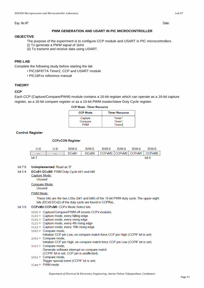
Each CCP (Capture/Compare/PWM) module contains a 16-bit register which can operate as a 16-bit capture
register, as a 16-bit compare register or as a 10-bit PWM master/slave Duty Cycle register.

EEE394 Microprocessor and Microcontroller Laboratory Lab #7
Department of Electrical & Electronics Engineering, Amrita Vishwa Vidyapeetham, Coimbatore
Page 72
PWM Mode
In Pulse Width Modulation (PWM) mode, the CCPx pin produces up to a 10-bit resolution PWM output. Since the
CCPx pin is multiplexed with the PORT data latch, the corresponding TRIS bit must be cleared to make the CCPx
pin an output.
A PWM output has a time-base (period) and a time that the output stays high (duty cycle). The frequency of the
PWM is the inverse of the period (1/period).
PWM Period
The PWM period is specified by writing to the PR2 register. The PWM period can be calculated using the following formula:
PWM period = [(PR2) + 1] • 4 • TOSC • (TMR2 prescale value), specified in units of time
PWM frequency (FPWM) is defined as 1 / [PWM period].
When TMR2 is equal to PR2, the following three events occur on the next increment cycle:
• TMR2 is cleared
• The CCPx pin is set (exception: if PWM duty cycle = 0%, the CCPx pin will not be set)
• The PWM duty cycle is latched from CCPRxL into CCPRxH
EEE394 Microprocessor and Microcontroller Laboratory Lab #7
Department of Electrical & Electronics Engineering, Amrita Vishwa Vidyapeetham, Coimbatore
Page 73
PWM Duty Cycle
The PWM duty cycle is specified by writing to the CCPRxL register and to the DCxB1:DCxB0 (CCPxCON<5:4>)
bits. Up to 10-bit resolution is available: the CCPRxL contains the eight MSbs and CCPxCON<5:4> contains the
two LSbs. This 10-bit value is represented by DCxB9:DCxB0. The following equation is used to calculate the PWM
duty cycle:
PWM duty cycle = (DCxB9:DCxB0 bits value) • Tosc • (TMR2 prescale value), in units of time
The DCxB9:DCxB0 bits can be written to at any time, but the duty cycle value is not latched into CCPRxH until
after a match between PR2 and TMR2 occurs (which is the end of the current period). In PWM mode, CCPRxH is a
read-only register. The CCPRxH register and a 2-bit internal latch are used to double buffer the PWM duty cycle.
This double buffering is essential for glitchless PWM operation. When CCPRxH and 2-bit latch match the value of
TMR2 concatenated with the internal 2-bit Q clock (or two bits of the TMR2 prescaler), the CCPx pin is cleared.
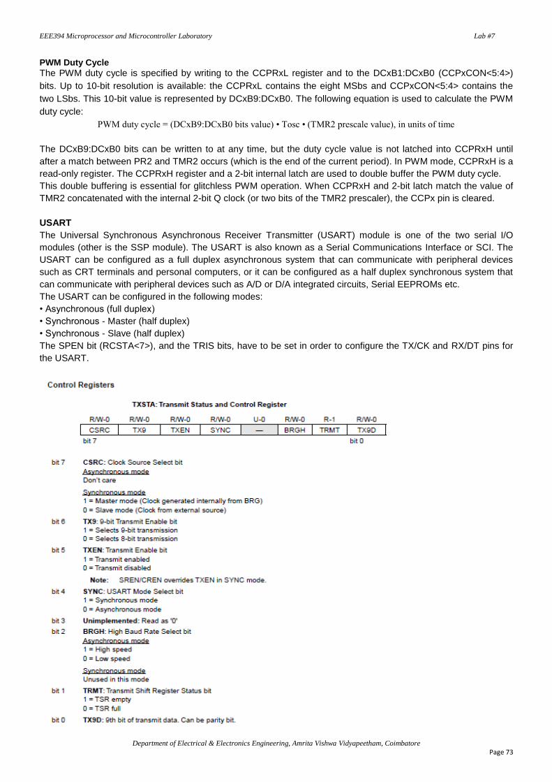
USART
The Universal Synchronous Asynchronous Receiver Transmitter (USART) module is one of the two serial I/O
modules (other is the SSP module). The USART is also known as a Serial Communications Interface or SCI. The
USART can be configured as a full duplex asynchronous system that can communicate with peripheral devices
such as CRT terminals and personal computers, or it can be configured as a half duplex synchronous system that
can communicate with peripheral devices such as A/D or D/A integrated circuits, Serial EEPROMs etc.
The USART can be configured in the following modes:
• Asynchronous (full duplex)
• Synchronous - Master (half duplex)
• Synchronous - Slave (half duplex)
The SPEN bit (RCSTA<7>), and the TRIS bits, have to be set in order to configure the TX/CK and RX/DT pins for
the USART.
EEE394 Microprocessor and Microcontroller Laboratory Lab #7
Department of Electrical & Electronics Engineering, Amrita Vishwa Vidyapeetham, Coimbatore
Page 74
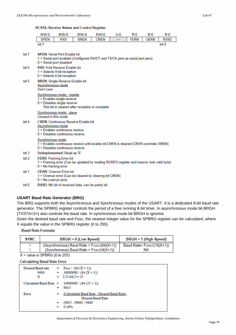
USART Baud Rate Generator (BRG)
The BRG supports both the Asynchronous and Synchronous modes of the USART. It is a dedicated 8-bit baud rate
generator. The SPBRG register controls the period of a free running 8-bit timer. In asynchronous mode bit BRGH
(TXSTA<2>) also controls the baud rate. In synchronous mode bit BRGH is ignored.
Given the desired baud rate and Fosc, the nearest integer value for the SPBRG register can be calculated, where
X equals the value in the SPBRG register (0 to 255).
EEE394 Microprocessor and Microcontroller Laboratory Lab #7
Department of Electrical & Electronics Engineering, Amrita Vishwa Vidyapeetham, Coimbatore
Page 75
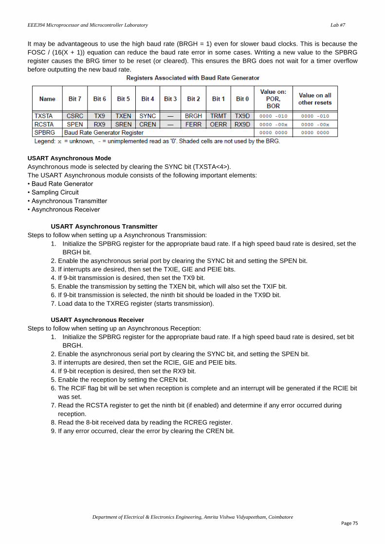
It may be advantageous to use the high baud rate (BRGH = 1) even for slower baud clocks. This is because the
FOSC / (16(X + 1)) equation can reduce the baud rate error in some cases. Writing a new value to the SPBRG
register causes the BRG timer to be reset (or cleared). This ensures the BRG does not wait for a timer overflow
before outputting the new baud rate.
USART Asynchronous Mode
Asynchronous mode is selected by clearing the SYNC bit (TXSTA<4>).
The USART Asynchronous module consists of the following important elements:
• Baud Rate Generator
• Sampling Circuit
• Asynchronous Transmitter
• Asynchronous Receiver
USART Asynchronous Transmitter
Steps to follow when setting up a Asynchronous Transmission:
1. Initialize the SPBRG register for the appropriate baud rate. If a high speed baud rate is desired, set the
BRGH bit.
2. Enable the asynchronous serial port by clearing the SYNC bit and setting the SPEN bit.
3. If interrupts are desired, then set the TXIE, GIE and PEIE bits.
4. If 9-bit transmission is desired, then set the TX9 bit.
5. Enable the transmission by setting the TXEN bit, which will also set the TXIF bit.
6. If 9-bit transmission is selected, the ninth bit should be loaded in the TX9D bit.
7. Load data to the TXREG register (starts transmission).
USART Asynchronous Receiver
Steps to follow when setting up an Asynchronous Reception:
1. Initialize the SPBRG register for the appropriate baud rate. If a high speed baud rate is desired, set bit
BRGH.
2. Enable the asynchronous serial port by clearing the SYNC bit, and setting the SPEN bit.
3. If interrupts are desired, then set the RCIE, GIE and PEIE bits.
4. If 9-bit reception is desired, then set the RX9 bit.
5. Enable the reception by setting the CREN bit.
6. The RCIF flag bit will be set when reception is complete and an interrupt will be generated if the RCIE bit
was set.
7. Read the RCSTA register to get the ninth bit (if enabled) and determine if any error occurred during
reception.
8. Read the 8-bit received data by reading the RCREG register.
9. If any error occurred, clear the error by clearing the CREN bit.
EEE394 Microprocessor and Microcontroller Laboratory Lab #7
Department of Electrical & Electronics Engineering, Amrita Vishwa Vidyapeetham, Coimbatore
Page 76
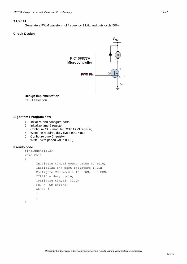
TASK #1
Generate a PWM waveform of frequency 1 kHz and duty cycle 50%.
Circuit Design
Design Implementation
GPIO selection
Algorithm / Program flow
1. Initialize and configure ports 2. Initialize timer2 register 3. Configure CCP module (CCP1CON register) 4. Write the required duty cycle (CCPRIL) 5. Configure timer2 register 6. Write PWM period value (PR2)
Pseudo code #include<pic.h>
void main
{
Initialse timer2 count value to zero;
Initialise the port registers TRISx;
Configure CCP module for PWM, CCP1CON;
CCPRIL = duty cycle;
Configure timer2, T2CON
PR2 = PWM period;
while (1)
{
}
}
EEE394 Microprocessor and Microcontroller Laboratory Lab #7
Department of Electrical & Electronics Engineering, Amrita Vishwa Vidyapeetham, Coimbatore
Page 77
Source code #1
Testing and Verification
(i) Check the output using Logic Analyzer in MPLAB IDE / implement the circuit in PROTEUS.
(ii) Implement the circuit in development board and verify the task.
Discussion & Inference
_____________________________________________________________________________________
_____________________________________________________________________________________
_____________________________________________________________________________________
_____________________________________________________________________________________
_____________________________________________________________________________________
_____________________________________________________________________________________
_____________________________________________________________________________________

EEE394 Microprocessor and Microcontroller Laboratory Lab #7
Department of Electrical & Electronics Engineering, Amrita Vishwa Vidyapeetham, Coimbatore
Page 78
TASK #2
Generate a PWM waveform of frequency 1 kHz. The duty cycle of the PWM generated should be 50%, if
the switch connected to the port pin is open, and 80% when it is closed.
Circuit Design
Algorithm / Program flow
EEE394 Microprocessor and Microcontroller Laboratory Lab #7
Department of Electrical & Electronics Engineering, Amrita Vishwa Vidyapeetham, Coimbatore
Page 79
Source code #2
Testing and Verification
(i) Implement the circuit in PROTEUS and verify the task.
(ii) Implement the circuit in development board and verify the task.
Discussion & Inference
_____________________________________________________________________________________
_____________________________________________________________________________________
_____________________________________________________________________________________
_____________________________________________________________________________________
_____________________________________________________________________________________
_____________________________________________________________________________________
_____________________________________________________________________________________
EEE394 Microprocessor and Microcontroller Laboratory Lab #7
Department of Electrical & Electronics Engineering, Amrita Vishwa Vidyapeetham, Coimbatore
Page 80
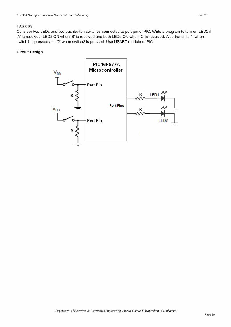
TASK #3
Consider two LEDs and two pushbutton switches connected to port pin of PIC. Write a program to turn on LED1 if
‘A’ is received; LED2 ON when ‘B’ is received and both LEDs ON when ‘C’ is received. Also transmit ‘1’ when
switch1 is pressed and ‘2’ when switch2 is pressed. Use USART module of PIC.
Circuit Design

EEE394 Microprocessor and Microcontroller Laboratory Lab #7
Department of Electrical & Electronics Engineering, Amrita Vishwa Vidyapeetham, Coimbatore
Page 81
Algorithm/Program flow
1. Configure high speed transmission, set BRGH.
2. Configure Baud rate as 9600. Move X value to SPBRG.
3. Configure Asynchronous mode of transmission.
4. Enable transmission.
5. Configure USART pins.
6. Check for transmission interrupt flag TXIF
7. Compare the received character and turn LEDs accordingly.
8. Transmit the character as per the conditions of push buttons.
Pseudo code
#include<pic.h>
Void main()
{
Initialise the port registers TRISx;
Initialise transmission and baud rate registers SPBRG, TXSTA;
Initialise receiver registers bits RCIF, RCSTA;
while(1)
{
if(character received = ‘A’)
{
LED1 = ON;
LED2 = OFF;
Clear RCIF & RCSTA;
}
else
if(character received = ‘B’)
{
LED1 = OFF;
LED2 = ON;
Clear RCIF & RCSTA;
}
else
if(character received = ‘C’)
{
LED1 = ON;
LED2 = ON;
Clear RCIF & RCSTA;
}
else
if(switch1 = ON)
{
Disable receive enable bit;
Transmit ‘1’;
Enable transmit enable bit;
while(register content full)
{
Disable transmit enable bit;
Enable receive enable bit;
delay(500);
}
}
else

EEE394 Microprocessor and Microcontroller Laboratory Lab #7
Department of Electrical & Electronics Engineering, Amrita Vishwa Vidyapeetham, Coimbatore
Page 82
if(switch2 = ON)
{
Disable receive enable bit
Transmit ‘2’;
Enable transmit enable bit;
while(register content full)
{
Disable transmit enable bit;
Enable receive enable bit;
delay(500);
}
}
}
}
Source code #3
EEE394 Microprocessor and Microcontroller Laboratory Lab #7
Department of Electrical & Electronics Engineering, Amrita Vishwa Vidyapeetham, Coimbatore
Page 83
Testing and Verification
Implement the circuit in PROTEUS and verify the task.
Discussion & Inference
_____________________________________________________________________________________
_____________________________________________________________________________________
_____________________________________________________________________________________
_____________________________________________________________________________________
_____________________________________________________________________________________
_____________________________________________________________________________________
_____________________________________________________________________________________
_____________________________________________________________________________________
_____________________________________________________________________________________
_____________________________________________________________________________________
EEE394 Microprocessor and Microcontroller Laboratory Lab #7
Department of Electrical & Electronics Engineering, Amrita Vishwa Vidyapeetham, Coimbatore
Page 84
UNDERSTANDING & LEARNING
_____________________________________________________________________________________
_____________________________________________________________________________________
_____________________________________________________________________________________
_____________________________________________________________________________________
_____________________________________________________________________________________
_____________________________________________________________________________________
_____________________________________________________________________________________
_____________________________________________________________________________________
_____________________________________________________________________________________
_____________________________________________________________________________________
_____________________________________________________________________________________
_____________________________________________________________________________________
_____________________________________________________________________________________
_____________________________________________________________________________________
_____________________________________________________________________________________
Prepared by:
Name: __________________________________________ Reg. No.: _________________________
Experiment Date: ……………
Report Submission Date: ……………
Submission Delay: …........
Signature
ASSESSMENT
Student Task Max.Marks Graded Marks
Pre-lab Preparation 10
Program flow / logic 10
Design / Implementation 10
Post-lab / Viva-voce 10
Total 40
Related Documents


![AT11626: SAM D SERCOM USART Configurationww1.microchip.com/.../Atmel-42539-SAMD-SERCOM-USART-Configuration... · AT11626: SAM D SERCOM USART Configuration [APPLICATION NOTE] 3 Atmel-42539A-SAMD-SERCOM-USART-Configuration_ApplicationNote_AT11626_092015](https://static.cupdf.com/doc/110x72/5e8569d49b115e518a2fc952/at11626-sam-d-sercom-usart-at11626-sam-d-sercom-usart-configuration-application.jpg)