101 FOUNDATIONS F O R C A P A C I T Y DESIGNED STRUCTURES P.W. Taylor * and R.L. W i l l i a m s ** SYNOPSIS This paper examines the application of capacity design methods to foundations. Results of research on foundation rocking are reviewed, and their implications included in the formulation of a rational design procedure. INTRODUCTION Capacity Design Procedure The principles of capacity design for earthquake-resistant structures are generally accepted amongst structural designers* Recog- nising that it is impractical to design the structure to resist elastically the extremely large acceleration forces which may arise in a truly major earthquake, the method adopted is to design the structure to resist, elastically, some lesser forces (the "design earthquake") then to check that the structure can undergo much larger deformations without serious damage. During these larger deform- ations the structure will behave as a mechanism in which yielding occurs at predictable locations. Such locations are detailed so that brittle failure is avoided and energy is dissipated. These concepts may be extended to the foundations of a structure and here also yielding may be permitted at predictable locations provided that such yielding can occur without serious damage. Application to Foundations The soil mechanics and structural aspects of foundation design are equally important. In describing soil-foundation interaction, the writers have attempted to integrate both aspects. The structural mechanisms considered in capacity design are described, some of which include rocking of foundations. This concept of foundation rocking is then described in some detail, structural design principles are outlined and, finally, examples of design incorporating these ideas are presented. MECHANISMS Examples of some simple mechanisms involving foundations are shown in Fig. 1. Ductile Frames (Fig, la) For a ductile frame to behave as a mechanism, a system of plastic hinges must form in the beams. If the foundations are unyielding, then hinges must also form in the columns near foundation level. * Professor and Head, Department of Civil Engineering, University of Auckland. ** District Structural Engineer, Ministry of Works & Development, Hamilton. An alternative solution, which may be considered preferable, is to use rocking foundations, in which the subsoil is allowed to yield, and column hinges are avoided. Rocking foundations are discussed in detail later in the paper. The recommendations^ of a group set up to study this topic included the following items: (i) Structural failure of foundations is not acceptable. Ductile yielding may be acceptable in members other than primary gravity resisting members provided they do not occur at load levels below that corresponding to SM=2. (For definitions of factors S and M refer to NZS 4203, The load level SM=2 is approximately 2,5 times the code lateral loading for the case.) (ii) Complete uplift of a limited number of column foundations may be acceptable. Ductile Coupled Shear Walls (Fig, lb) These are similar to ductile frames except that uplift of entire foundation elements is not acceptable. Ductile Cantilever Shear Walls or Columns (Fig, lc) The foundation should be designed to exceed the overstrength of the wall or column without yield occurring in the foundation soil. Partial lifting is usually acceptable. Rocking Foundations (Fig. Id) This is not yet recognised as a distinct structural type (in NZS 4203 Table 5). It would be logical to define this as an additional structural type in which foundation rocking forms the principal mode of yielding and energy dissipation. These structures must be capable of rocking without failure of the foundation structure. The structural foundation and superstructure must be capable of with- standing at reliable strength the over- strength forces generated under rocking. Pile Foundations (Fig, le) It is feasible to consider pile foundations either as sliding in skin BULLETIN OF THE NEW ZEALAND NATIONAL SOCIETY FOR EARTHQUAKE ENGINEERING, VOL. 12, NO. 3 JUNE 1979

Welcome message from author
This document is posted to help you gain knowledge. Please leave a comment to let me know what you think about it! Share it to your friends and learn new things together.
Transcript

101
F O U N D A T I O N S F O R C A P A C I T Y D E S I G N E D S T R U C T U R E S
P.W. T a y l o r * and R.L. W i l l i a m s **
SYNOPSIS
This paper examines the application of capacity design methods to foundations. Results of research on foundation rocking are reviewed, and their implications included in the formulation of a rational design procedure.
INTRODUCTION
Capacity Design Procedure
The principles of capacity design for earthquake-resistant structures are generally accepted amongst structural designers* Recognising that it is impractical to design the structure to resist elastically the extremely large acceleration forces which may arise in a truly major earthquake, the method adopted is to design the structure to resist, elastically, some lesser forces (the "design earthquake") then to check that the structure can undergo much larger deformations without serious damage. During these larger deformations the structure will behave as a mechanism in which yielding occurs at predictable locations. Such locations are detailed so that brittle failure is avoided and energy is dissipated. These concepts may be extended to the foundations of a structure and here also yielding may be permitted at predictable locations provided that such yielding can occur without serious damage.
Application to Foundations
The soil mechanics and structural aspects of foundation design are equally important. In describing soil-foundation interaction, the writers have attempted to integrate both aspects. The structural mechanisms considered in capacity design are described, some of which include rocking of foundations. This concept of foundation rocking is then described in some detail, structural design principles are outlined and, finally, examples of design incorporating these ideas are presented.
M E C H A N I S M S
Examples of some simple mechanisms involving foundations are shown in Fig. 1.
Ductile Frames (Fig, la)
For a ductile frame to behave as a mechanism, a system of plastic hinges must form in the beams. If the foundations are unyielding, then hinges must also form in the columns near foundation level.
* Professor and Head, Department of Civil Engineering, University of Auckland.
** District Structural Engineer, Ministry of Works & Development, Hamilton.
An alternative solution, which may be considered preferable, is to use rocking foundations, in which the subsoil is allowed to yield, and column hinges are avoided. Rocking foundations are discussed in detail later in the paper.
The recommendations^ of a group set up to study this topic included the following items:
(i) Structural failure of foundations is not acceptable. Ductile yielding may be acceptable in members other than primary gravity resisting members provided they do not occur at load levels below that corresponding to SM=2. (For definitions of factors S and M refer to NZS 4203, The load level SM=2 is approximately 2,5 times the code lateral loading for the case.)
(ii) Complete uplift of a limited number of column foundations may be acceptable.
Ductile Coupled Shear Walls (Fig, lb)
These are similar to ductile frames except that uplift of entire foundation elements is not acceptable.
Ductile Cantilever Shear Walls or Columns (Fig, lc)
The foundation should be designed to exceed the overstrength of the wall or column without yield occurring in the foundation soil. Partial lifting is usually acceptable.
Rocking Foundations (Fig. Id)
This is not yet recognised as a distinct structural type (in NZS 4203 Table 5 ) . It would be logical to define this as an additional structural type in which foundation rocking forms the principal mode of yielding and energy dissipation.
These structures must be capable of rocking without failure of the foundation structure. The structural foundation and superstructure must be capable of withstanding at reliable strength the over-strength forces generated under rocking.
Pile Foundations (Fig, le)
It is feasible to consider pile foundations either as sliding in skin
B U L L E T I N OF T H E NEW Z E A L A N D N A T I O N A L SOCIETY FOR E A R T H Q U A K E E N G I N E E R I N G , V O L . 12, NO. 3 JUNE 1979

102
friction or as piles with reinforcement yielding in tension and compression. Although the authors regard this as a satisfactory foundation type, and similar design procedures can be followed, it is not considered further in this paper.
Base Isolation (Fig. If)
Base isolation devices together with energy dissipators provide a further possibility. These are described in the papers by Megget at this conference.
ROCKING OF FOUNDATIONS
Examples of Rocking
It has frequently been observed that walls and structures that should have fallen during earthquakes have stood, even if in a damaged condition. After the Tongan Earthquake June 1977 one of the authors observed many walls that could be rocked by hand, but had not fallen, and monuments that did not fall despite their relatively small size(2)^ Muto, Uremura and Sonobe^ ' carried out tests and concluded that typical slender Japanese buildings would not overturn during earthquakes, despite the design overturning moments being greater than their restoring moments. Other examples of foundation rocking are quoted by Priestley, Evison and C a r r ^ .
Elastic Rocking
If overturning moments applied to a footing are small enough, it will remain in full contact with the supporting soil, and elastic deformation of the soil will give the foundations some compliance. Elastic theory can then be applied, the stiffness being a function of the elastic properties of the soil and the footing dimensions.
This is the approach used in analysing the vibrations of foundations for machines with out-of-balance forces. Usually such forces are comparatively small and the assumptions that the soil behaves as a linear elastic material and that the foundation remains in full contact are reasonable.
Separation of Footing and Subsoil
If the overturning moment is sufficiently increased, one edge of the footing may lift off the supporting subsoil. Making the simplifying assumption that the foundation material acts as a bed of springs (a Winkler foundation, Fig. 2) the footing is found to lift at one edge when the eccentricity of loading exceeds B/6 (where B is the foundation breadth) as shown in Fig. 3(c). When this occurs, the moment-rotation relationship becomes non-linear, rotational stiffness reducing with further rotation, as shown in Fig. 4. The model considered so far has only linear elastic elements, and it is perhaps surprising to find this non-linear moment-rotation behaviour, which arises from the changing geometry of the situation.
On reducing the moment, the same (nonlinear) relationship applies and the deformation is fully recoverable.
Soil Yield
The Winkler foundation model can be extended to include yield; that is, the springs representing the soil can be assumed to behave elastically until some ultimate yield stress, q u is reached (Fig. 5(a)). As footing rotation is increased, an area beneath which plastic deformation is occurring will form at one edge with uniform contact stress.
With further rotation, stress distribution tends to the ultimate condition (Fig. 5(c)). If the applied moment is reduced to •zero, after yield in both directions, contact may still be re-established over the whole area (and the initial rotational stiffness restored) as in Fig. 5(d). Other-wide, if plastic yielding has been greater, the edges may no longer be in contact and the stiffness is permanently reduced (Fig. 5(e) ) .
The vertical load bearing capacity is not reduced, however. If the vertical load, V, were increased, full contact would be re-established before failure could occur. Unless there has been some reduction in yield strength, the factor of safety against shear failure under vertical load, F v , will be the same as it was initially.
During cyclic rocking with yield, the moment rotation relationship shows a hysteresis loop; that is, energy is being dissipated by plastic deformation of the soil. If there is an adequate safety factor for axial loading the model predicts that yielding will occur only in the first cycle of loading. There will be some resulting vertical deflection of the footing as a whole, the amount of which will depend on the rotation amplitude.
Tipping Foundations
The extreme case of a rigid, unyielding foundation material may be considered. Then the footing may pivot about one edge while the other rises off the supporting material. This mode of action was described by Housner( ' and is referred to by Meek ' as "tipping". It is described in detail by Priestley, Evison and Carr^ '.
Tests on Clay Soils
Despite the gross simplifications made in the theoretical analysis, experimental results from tests carried out at the University of Auckland on model footings (500 mm x 250 mm) on saturated clay have confirmed the theoretical predictions remarkably closely as illustrated in Figs. 6 and 7 ^ ' . The moment-rotation behaviour is seen to be strongly non-linear, the tangent stiffness at 0.03 5 radians rotation amplitude (when yielding had occurred) being only about one tenth of that at 0.0 05 radians, when the footing remained wholly in contact with the soil. At the larger amplitude, considerable energy dissipation occurred in the first cycle of loading, as evidenced by the area within the hysteresis loop, but less in subsequent cycles.
The displacement diagram (Fig. 7) gives

103
FIG 1Q DUCTILE FRAMES ( $ = 0 8 )
Plastic hinges
( i ) Strong foundation (ii) Rocking foundation (iii) Foundation failing
FIG 1b DUCTILE COUPLED SHEAR WALLS ( S = 0 - 8 )
( i ) Strong foundation (i i) Rocking foundation (iii) Foundation failing
FIG 1c DUCTILE CANTILEVER SHEAR WALL (S=1-0 or 1-2) OR COLUMN (S = 2]
W a l l Column
FIG 1d ROCKING FOUNDATION FOR CANTILEVER STRUCTURE ( S = 1-4?.
//AW"
Foundation failing
FIG 1e YIELDING OR PUMPING PILE FOUNDATION
Piles with yielding reinforcing
FIG If BASE ISOLATION DEVICE
T T Piles sliding with
skin friction
Damper
— — S l i d i n g bearing
EXAMPLES OF MECHANISMS

104
vertical movement at the centre of the footing and shows that, when uplift of one edge occurs, the gravity load is raised. (This is one mode of storage of recoverable potential energy during cyclic loading.) It also shows that, after five cycles of large-amplitude rocking, permanent vertical deformation of 1 mm had occurred (0.2% of the footing dimension normal to the axis of- rocking). In this respect, the model behaviour differed from the theoretical prediction. (According to the theory, no further vertical deformation occurs after the first cycle of loading.)
The general conclusion to be drawn from this research is that, provided there is a reasonably high factor of safety against failure under vertical axial load, rocking of the footing (with plastic yielding of the soil) may occur without any real disadvantage.
Footings on Sands
Footings on sands differ from those on clay in that the bearing pressure at yield is strongly dependent on the breadth of the contact area.
In the design of foundations on cohension-less .soils, dimensions are very often controlled by considerations of settlement. As a result, the factor of safety against bearing failure under axial load may be considerably higher than necessary from consideration of stability alone.
The contact stress for a surface footing, loaded axially to a yield condition is known to increase from zero at the edges to a maximum at the centre.
When an increasing moment, M,is applied to a footing with constant vertical load V, the eccentricity increases, one edge lifts slightly while at the other edge the stress distribution approaches this limiting condition , as shown in Fig. 8(a).
With further rotation in the same direction, yielding at constant stress occurs. After large amplitude rocking, the stress distribution under axial load will be as shown in Fig. 8(b), the footing no longer being in contact with the foundation at the edges. It should be noted that in this case also, the factor of safety against failure under vertical load has not been reduced. If the axial load is increased, full contact will be restored. Rocking tests on model footings on sands are now proceeding at the University of Auckland. The behaviour is in agreement with the explanation given above. While the work has not reached a stage where final conclusions can be drawn, it appears from the results to date that these will not differ greatly from those for clays. That is, rotational yielding is permissible beneath foundations and provides a useful form of energy dissipation. Preliminary tests indicate, however, that a rather larger factor of safety (in axial loading) may be desirable to avoid significant vertical deflection during rocking.
APPLICATION OF BEARING CAPACITY THEORY
General
expressed:
q = c N + yD N T i |B N u c q 2 Y
where c is the cohesion of the soil Y is its (weight) density B is the breadth of the footing
and N^, N^ and Ny are bearing capacity depending only on <J>, the angle of shearing resistance of the soil' ' . More exact values of these factors were presented by Meyerhof (9) which are now commonly used.
The foundation must be designed to transfer the full base shear, either by passive resistance against vertical surfaces of foundation elements, or by friction and adhesion on the horizontal surfaces. As there must be some horizontal movement before passive pressures are realised, it is considered that friction and adhesion forces will be mobilised first. The resultant loading on the foundation material is therefore inclined to the vertical. For inclined loads (inclination a to the vertical) the bearing capacity factors have been shown (10) to reduce as follows:
For the vertical component of the load,
N and N should be multiplied by 1 -c q 90 c
and N should be multiplied by 1 -
Clay Soils
"Total stress analysis" is used in the design of footings on saturated clays which behave as (cj) = 0) materials. In the case N = 1 and N y = 0. The factor N c is to some extent a function of the depth and shape of the footing. When considering design under rocking conditions, the depth, D, is zero (because of separation of the footing from the foundation material) and the breadth B is usually small in comparison with the length (normal to the axis of rocking) of the contact area. Under these conditions, the value of N c tends to its minimum value, 5.14 (= IT + 2) reduced, if necessary for inclination, as above.
The expression for ultimate bearing capacity on clay, under these conditions, becomes:
c N
where the cohesion, c, is the undrained shear strength.
Sands
"Effection stress analysis" is applicable in this case, and allowance must be made for the effect of the water table, if it is within a depth, below the base of the foundation , equal to its breadth, B.
When considering rocking, the depth, D should be taken as zero. On a cohesionless soil, the Terzaghi formula then reduces to:
The ultimate bearing capacity of a rigid strip footing with a central load may be
\ = 2 Y B ' N

105
where B 1 is the breadth of the loaded area and Ny is dependent on the angle of
shearing resistance of the soil, reduced if necessary for inclination.
Basis for Selecting Footing Sizes
When eccentric loads are considered in design, the accepted practice is to use the Meyerhof hypothesis, which assumes the contact stress to be uniform over a part of the footing width B' = B - 2e as shown in Fig. 5(c). (This is similar to ultimate strength design of concrete.)
Bearing capacity theory, as outlined above is then applied with the reduced breadth B' replacing B ^ 1 0 ' *
Given the design vertical load, V and overturning moment, M, the eccentricity 3 = M/V is found.
For a footing of length L (parallel to the axis of rocking) the required contact breadth is given by:
B 1 = V F L a
where F is the appropriate factor of safety for the design loadings considered,
and q is the ultimate bearing capacity u based on known soil properties.
In line with concrete design terminology, this is referred to as "ideal bearing pressure" in the design examples appended.
For clay of a given strength, q u has a unique value (noted above) but for a cohesion-less soil it is proportional to the breadth of the loaded area (q - i Y B' N ) .
u 2 Y Hence, for sands:
T1 B V F L y B 1 N
(B 1 ) = 2V F L Y N Y
The footing should then, if practicable, be proportioned to accommodate this loaded area. Assuming symmetry, the required breadth
B 2(e + B 8/2)
Factors of Safety
For design earthquake loading, factors are applied (NZS: 4203) to actual loads to obtain design loads. This provides a factor of safety, but one that is inadequate for
mechanics problems. It has been shown that, for factored load design, an
additional factor of safety of 1.8 should be applied to give a suitable safety margin. That is, the "ideal bearing pressure" is divided by 1.8 to give the "reliable bearing pressure" as designated in the design examples with this paper.
In design for capacity loadings, a much lower factor of safety is tolerable, and a value of 1.1 is recommended(1^, and has been
used in the design examples.
Soil Sensitivity and Liquefaction
Cohesive soils are reduced in strength by remoulding, sensitivity being defined as the ratio of undisturbed strength to fully remoulded strength. Complete remoulding (using a spatula) is, of course, a much more drastic treatment than the soil can receive under a foundation, even in a severe earthquake. It has been shown (for example by Seed( 1 2^) that cyclic deformations of even quite high amplitudes, do not result in great diminution in the strength of most clays.
Saturated cohesionless soils, particularly if not well compacted, may be subject to liquefaction under earthquake loadings. Observations in the Niigata earthquake of 1964 , where liquefaction was widespread, indicated that it occurred as much under open spaces as under building foundations. Conditions under which liquefaction is possible are easily recognisable. Such possibility should, of course, be investigated, but this aspect is not considered in this paper. Also, problems concerned with foundations on sloping sites have not been considered.
STRUCTURAL DESIGN
Foundation Types
The foundation type must first be selected. This is related to the structural mechanism adopted (Fig. 1 ) . Foundation types have been designated A, B, C, D and E in Fig. 9, which is a decision table for design of the foundation structure. (While, at first glance, this appears formidable, it may be more readily comprehended by following through a single foundation type.) The design examples follow this procedure. It should be noted that with frame type structures (type C, D and E) the lateral loading generates axial loading on the foundations due to weight transfer whereas a similar loading on the cantilever types (A and B) does not affect the axial loading.
Design Loading
In the case where the superstructure is to be protected by rocking (type A) the rocking becomes the primary lateral load resisting mechanism and is designed to code loadings.
In cases where the structure is designed to hinge_above the foundation the overstrength moments M of the column elements are used together with the maximum or minimum axial loads that can occur, thus maintaining the mechanism in the superstructure. In frame type buildings (types C, D, E) these loads may occur when the superstructure reaches its capacity lateral loading. The axial loads generated by this lateral loading are pmax and Pmin- (Pmin i s generally negative.)
The N.Z. loading code (NZS 4203 CI. 3.3.6.3.1) states that no foundation system need be designed to resist forces and moments greater than those resulting from a horizontal force corresponding to SM=2. Despite this load limitation the authors strongly recommend that protection from

FIG 2 THE WINKLER FOUNDATION MODEL
s// <^ ^ \// '> > ;
FIG 3 FOUNDATION ROCKING
Deformations-. w _ j u _ e = T
— B i — - I (a) (b)
Contact stress: I t t t T t t
" 1 - e > 6
( 0
FIG 4 MOMENT ROTATION RELATIONSHIP
^ Fully yielding moment
-Point of separation
FIG 5 ROCKING WITH YIELD
Contact stress-.
T
I Soil deformation
<c>*J
^Zone of yielding
(e)
FIG 6 MOMENT - ROTATION BEHAVIOUR,
FIG 7 DISPLACEMENT -ROTATION BEHAVIOUR,
Deformation (mmJ
-G-Ot, - 0-02 0 0-OZ 004
R O T A T I O N ( r n c J i a n s )
FIG 8 ROCKING ON SAND,
(a)

107
damage for loadings beyond this limit be maintained.
The footings of normal frame and coupled shear wall type buildings may be allowed to rock at SM=2. If M e and P e
a r e the moments and axial loads generated by the code lateral load, these values are increased by a factor of 2.5 in most normal cases. Note that P e may have +ve and -ve values.
A further provision of the N.Z. loading code, NZS 4203, CI. 3.3.6.2.2, allows total uplift of entire foundation elements of ductile frames provided not more than one quarter of the total number of such elements uplift for deformations in any direction. Protection from damage under these conditions is also strongly recommended.
Sources of resistance to uplift are:
1. Self weight plus weight of soil uplifted by the footing.
2. Cohesion on sides of footing and on soil uplifted.
3. Suction effects. (Up to 100 kPa is possible but negligible if hardfill is used under the footing.)
4. Vertical acceleration of centre of mass due to rotation. (This depends on the geometry of overturning and the net acceleration but is generally very small.)
Size of Foundation Pads
For overturning forces this may be determined by adding the required lever arm to one half of the appropriate stress block as outlined earlier in the paper to give half the breadth of the footing required. As loadings for type A are code loadings, reliable bearing pressure should be used. For types B, C, D and E the loadings are at capacity and the ideal bearing pressure -r 1.1 may be used.
The foundations must also be sized for the code gravity load at reliable bearing pressure and for settlement considerations under the long term loading. In case E where there is a load limitation of SM=2, the authors recommend that the foundation should be checked for the high axial compression load generated by the capacity lateral loading, D + L R + pmax, in the end columns. This loading may be resisted by the ideal bearing pressure -r 1.1, but under this condition resistance to rotational moment is not required.
Design of Foundation Pads
Foundation pads are primarily gravity resisting elements and should be protected from damage under all circumstances. The structure should therefore be designed to reliable stress levels as required by the concrete code. In cases where rocking can occur (types A and E) the effects of the worst soil stress block should be considered. This occurs when the maximum axial load forms an "overstrength" soil stress block adjacent to the edge of the footing. (A line reaction at the edge of the slab will produce a conservative result.) In the case of rocking at SM=2 (type E) the pad should be designed for the high axial load case as mentioned above. Where uplift or partial uplift is possible pads should be reinforced to resist
the maximum uplift forces than can be generated due to the self weight and weight of soil uplifted, etc.
Design of Foundation Beams
In the strong beam case, type C, the foundation beams should be designed to resist at reliable strength the overstrength moment of the column element under the range of axial loads considered. Alternatively the moment generated at SM=2 may be used. Where the SM=2 limit is used or if uplift is possible the beam should be detailed for ductility and it is recommended that at least one face of these beams should be made accessible for inspection so that any damage due to yielding may be detected.
DESIGN EXAMPLES
The first example illustrates that the foundation may be designed to rock under earthquake conditions, thus obviating the necessity to design the superstructure for the requirements of ductility.
Use of the proposed new structural type, where foundation rocking forms the principal mode of yielding and energy dissipation, is illustrated in Example 2. (A structural type factor S=l. 4 is suggested.) Conventional design of the superstructure would result in unrealistically large foundation size.
Example 3 illustrates design of a foundation for a single ductile yielding column.
Example 4 illustrates two alternative foundation systems for a reinforced concrete ductile frame. In the first, strong foundation beams are used to force yielding at the bases of the columns. In the second, rocking of individual footings may occur and slightly larger footings are required. As nominal tie beams only are required, it is considered that this should provide a more economical solution.
CONCLUSIONS
An attempt has been made to present a rational procedure for the design of foundations for earthquake-resisting structures. Perhaps because this topic is on the boundary between structural and foundation engineering, it has not previously received the attention it deserves. Some relatively new concepts are included such as capacity design, uplift and rocking of foundations. It is hoped that this will prove of practical value to designers.
BIBLIOGRAPHY
1. Allardice, N. W., Fenwick, R. C., Taylor, P. W. and Williams, R. L., "Seismic Design of Ductile Moment Resisting Frames; Section D: Foundations for Ductile Frames". Bull. N.Z. Nat. Soc. Earthquake Eng., V. 11, No. 2, pp. 122-128 (June, 1978).
2. Campbell, M . D., McKay, G. R. and Williams, R. L., "The Tonga Earthquake of 23 June, 1977 - Some Initial Observations" . Bull. N.Z. Nat. S o c Earthquake Eng., V. 10, No. 4, pp. 208-218 (Dec 1977.
1 0 8
3. Muto, K., Uremura, H. and Sonobe, Y., "Study of the Overturning Vibration of Slender Structures". Proc. 2nd World Conference Earthquake Eng. (Tokyo), V. II, pp. 1239-1261 (1960) .
4. Priestley, M. J. N., Evison, R. J.- and Carr, A. J., "Seismic Response of Structures Free to Rock on their Foundations". Bull. N.Z. Nat. Soc. Earthquake Eng., Vol. 11, No. 3, pp. 141-150 (Sept. 1978) .
5. Housner, G. W., "The Behaviour of Inverted Pendulum Structures During Earthquakes". Bull. Seism. Soc. of Am., Vol. 53, No. 2, pp. 403-417 (Feb. 1963).
6. Meek, J. W., "Effects of Foundation Tipping on Dynamic Response". Jour. Struct. Div. ASCE., Vol. 101, No. ST7, pp. 1297-1311 (July, 1975).
7. Bartlett, P. E., "Foundation Rocking on a Clay Soil". M.E. Thesis, University of Auckland. Also published as Univ. of Auckland, School of Eng. Report No. 154 (Nov. 1976).
8. Terzaghi, K., "Theoretical Soil Mechanics". John Wiley (1943) .
9. Meyerhof, G. G., "Ultimate Bearing Capacity of Foundations". Geotechnique. Vol. 2, No. 4, pp. 301-332 (Dec. 1951) .
10. Meyerhof, G. G., "The Bearing Capacity of Foundations under Eccentric and Inclined Loads". Proc. 3rd Int. Conf. S.M.F.E. (Zurich). Vol. 1, pp. 440-449 (1953).
11. Taylor, P. W. , "Code Provisions Related to Soils and Foundations". Bull. N.Z. Nat. Soc. Earthquake Eng., Vol. 9, No. 1, pp. 68-73 (March, 1976).
12. Seed, H. B., "Soil Strength during Earthquakes". Proc. 2nd W.C.E.E., (Tokyo), Vol. 1, pp. 183-194 (1960).
This paper was presented at the South Pacific Regional Conference on Earthquake Engineering held in Wellington on 8, 9 and 10 May, 1979.

109
ESTABLISH FOUNDATION TYPE
T A R T t
Axial load does not vary with lateral load; ie Cantilever Type
Axial load varies with lateral load; ie Frame or Coupled Shear Wall Type
Superstructure protected by rocking foundation; fig. 1 d .
TYPE A
Design for structure hinging; fig. 1 c .
TYPE B
Design for structure hinging; fig. 1 a (i)„ and fig. 1 b (i)_ Strong Beams
I TYPE C
Large Pads
I TYPE D
Foundation material yielding at S M > 2 fig. 1 a (ii).and
fig. 1 b (iih
TYPE E
ESTABLISH FOOTING SIZE using type selected above
S T A R T Establish code vertical and lateral loads D, L^, E at foundation level !
Establish overturning moment TYPE A Due to code lateral load
5, C , D Due to overstrength moment at column Base* JJ at max or min axial loads. Type C may use Type E value if less, with appropriate detailing. E Due to moment generated at lateral load "corresponding to SM = 2 (use Type D value if less)
Establish min/max axial loads TYPE A, B at code loading
TT, D~ at capacity of superstructure E* aT lateral load corresponding to SM = 2
I Min
Type A, B ,9D C , D ,9D ( N B " ~ P _
Type + P - *
m m -ve) m m
E .9D - 2,5 P,
Max A D B D C,D E D
1.3 L R
"R % + 2
L~ + P. max 5 P.
(Use Type D value if greater) ( U s e ^ D ™ l n e i f l e s s }
Type. C Only
Moment taken by foundation beams
Min Case i
Establish lever arm required (except Type C ) . | Establish half breadth of stress block. Type A At reliable bearing pressure; ie ide*al soil pressure *• 1.8 B, C , D, E At ideal bearing pressure + 1.1 (Type D also check code loading at reliable bearing pressure.) I
Add half breadth of stress block to lever arm and establish footing size.
Max Case As for min case
Check total uplift. Ignore cases where allowable under NZS 4203 CI.3.3.6.2.2.
Type C and E Only \
\
Check footing size for settlement
Check footing size for 1.4 D + 1.7 "L-o reliable bearing
at Check footing size for D + L, and zero moment at** ideal bearing pressure • 1.1
;max
Type C and E Only
Select largest footing size
NOTE: For D, 1^ E refer NZS 4203.1976. For Load limitation SM > 2 for foundation design refer NZS 4203 CI.3.3*6.3. Pe is axial load generated by code level earthquake loading. P m i n > P m a y are axial loads from capacity design of superstructure. W is overstrength moment of column at the corresponding capacity design axial loads.
F I G U R E 9 : D E C I S I O N T A B L E F O R D E S I G N O F F O U N D A T I O N S T R U C T U R E

Example 1
Problem: Footing of tower for pedestrian footbridge (see Dia 1 (a). Design footing to protect legs and holding down bolts as they are not considered to be suitable energy dissipating elements; i e TYPE A.
. Ideal bearing pressure of the soil = 300 kPa Lateral load from code (wind governs at code level but ductility
required for seismic case) = 1 2 0 kN Moment at base = 1 2 0 x 5 . 2 m = 624 kN.m Reliable bearing pressure of soil = ™ 2 2 _ 167
Dia (a)
w v w
45 m ( 45m i 4 5 m
5-2m
(b)
S B'
(0
i \ k
11ml 2-4m J 1 m
Min axial load during earthquake = 0.9 D = 0 . 9 (370 superstructure + 1 3 0 say foundations) = 450 kN Eccentricity, e, required (see Dia 1 b )
624 kN.m . = 450 kN = 1 ' 3 9 m
Max axial load during earthquake = D + 1 - 3 1 ^
= (370 + 1 3 0 ) 4- 1 . 3 * 3 6 0
= 968 kN e required
Assume width of footing = 2 m Breadth of stress block, B f, = *
Breadth of footing required = 2 (e + B ' ) = 2 (e + B » ) =
2 2
2 ( 1 . 3 9 + = 4 . 1 4 m 2 ( . 6 4 + ~ ^ ) = 4 . 1 8 m
Also check 1*4 D = 1 . 7 gravity only loading case and settlement. Select footing size 4 . 4 m x 2 m. Check tower legs, holding down bolts and footing for worst feasible soil reaction. Consider R at edge of footing. This is too conservative in this case. Therefore consider R from overstrength stress block,, Say overstrength of soil = 600 kPa*
B* s= s^y^^ - - 8 1 m ." . R is , 6 rn aoprox from X see dia 1 (c). 600 x 2 . 0
• t t r + i /968 x . 6 + 130 x 1 . 2 N l n „ . Force in L H tower leg = - (̂ ^—^ — — ) = - 3 0 7 kN
Resolve forces at base of tower. Force in R H leg = 968 - 130 - ( - 3 0 7 ) = 1 1 4 5 kN.
Check leg and holding down bolts for the force and footing for applied moment at reliable stress levels.
Example 2
Problems A reinforced concrete cantilever wall for external staircase with support in one direction provided by links to existing building. Design for rocking foundation in direction of wall? ie TYPE A (see Dia 2 (a)).
Ideal bearing pressure of soil = 300 kPa D L = 2 2 5 kN y- « 2 5 kN
W t = D L + ~ = 2 2 5 + 25 = 250 kN (superstructure only)
Say Structural Type factor = 1 . 4 for rocking foundation Seismic lateral force V = C.I.S.M.R.Wt (Refer NZS 4203)
= . 1 2 5 x 1 . 3 x 1 . 4 x 1 x 1 x 250 = 57 kN at a height of 8 m Overturning moment at code level = 57 x 8 = 456 kN.m Reliable bearing pressure of soil = ™ S = 167 kPa.

Dia 2
( 0
Min axial load during earthquake m 0.9 D e 0.9 (Wt superstructure and foundation + soil uplifted)
= 0.9 (250 + 100 + 5 0 )
= 360 kN Eccentricity, e, required - $ [ - 1 . 2 7 .
Assume length of footing = 2 m Breadth of stress block, B , at reliable bearing pressure «
Required breadth of footing «= 2 (e + B^) = 2 ( 1 . 2 7 + = 3 .615 m
Max axial load during earthquake - » + 1 . 3 ^
= (250 + 100 + 50) + 1 . 3 x 75
497-5 kN
456 required =^^_= 0.92 m
B . - 42L2_ * ~ 167 x 2.0 1.4? m
2 (e + B') = 2 ( .92 + ^ | * ) 2
= 3 . 3 m
Also check 1 . 4 D + 1 . 7 ^ gravity only case and D + y settlement ease. Select footing size 3 .8 m x 2 m.
Now design wall and footing for worst feasible loads under rocking. Assume R at edge of footing.
R max = 497.5 kN e = y = 1 . 9 m Design wall for 497-5 x 1 .9 « • 945 kN.m and axial load of 433 kN. Design footing for worst feasible soil pressure. Soil pressure will be greater than 300 kPa. Design for this pressure as a rectangular stress block but extra steel at extremity and for distribution steel see Dia 2 (o).
Example 3
Problem: Centre column of large industrial building (see Dia 3 ) .
Design a pad footing for ductile yielding column; i e TYPE B.
. 1 2 5 x 1 . 3 x 2 x 1 x 1
8 m Design column = C.I.S.K.R.
V = .33 x 50 kN = 16.7 kN M code e 133.6 kN.m 450 x 450mm column 8 D20 bars Overstrength moment M = 212 kN.m
.33
(f 344 MPa, cf> = 1.0) Try Pad 2.8 m x 2 . 8 m x 0.6 m Wt of Pad and column = 145 kN D = 50 + 145 = 195 kN
Min axial load during earthquake = . 9 D = .9 x 195 = 175.5 kN Eccentricity "e" required
1 . 2 1 m 2 1 2 1 7 5 - 5
Breadth of stress block, Bl
at ideal bearing pressure
1 7 5 . 5 2 .8 x 300 = 0.23 m
1.1
1.1
= 50 kN Max axial load during earthquake D + 1 ^ = 195 + 50 « 245 kN
2 1 2 e = 245 = O.87 m
B' 245 2.8 x 300
T7T - 0.32 m
2 (e + B T )
2
« 2 ( 0 . 8 ? + — ) = 2.06 m
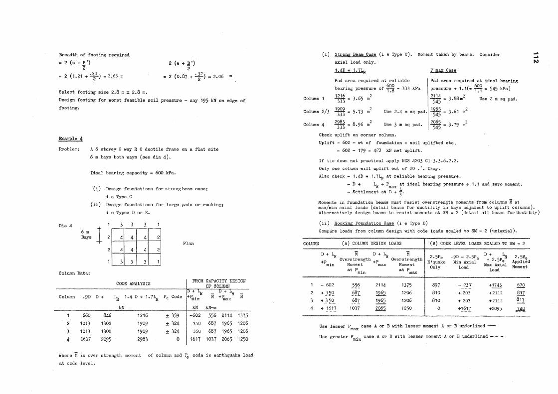
Select footing size 2 .8 m x 2 . 8 m. Design footing for worst feasible soil pressure - say 195 kN on edge of footing.
Breadth of footing required « 2 (e + B ')
2
«= 2 ( 1 . 2 1 + = 2.65 m
A 6 storey 2 way R C ductile frame on a flat site 6 m bays both ways (see dia 4)«
Ideal bearing capacity « 600 kPa.
(i) Design foundations for strong beam case; i e Type C
(ii) Design foundations for large pads or rocking; i e Types D or E.
Dia 4 , 1 3 3 3 1 6 m Bays 2 4 4 4 2
2 4 4 4 2
1 3 3 3 1
Column Data:
CODE ANALYSIS P R O M CAPACITY DESIGN OP COLUMN
Column .9D D + L R 1 - 4 D 4- 1 . 7 1 ^
kN
P E Code D + ^
kN
M
kN-m
D + Lp + P ^ M max
1 660 846 1 2 1 6 ± 359 - 6 0 2 556 2 1 1 4 1375 2 1013 1 3 0 2 1909 ± 324 3 5 0 687 1965 1206
3 1013 1302 1909 + 324 3 5 0 687 1965 1206
4 1 6 1 7 2095 2983 0 1617 1037 2065 1250
Where M is over strength moment of column and P E code is earthquake load at code level.
Example 4
Problem:
(i) Strong Beam Case (i e Type C). Moment taken by beams. Consider axial load only. 1.4D + 1*7Ifr P max Case
fS5
Pad area required at reliable bearing pressure of = 333 kPa
Column 1 1216
333 3.65 m
Column 2 /3 - ^ i = 5 . 7 3 m
2
Column 4 2983 333
8.96
Use 2 . 4 m sq pad,
Use 3 m sq pad.
Pad area required at ideal bearing pressure * 1 . 1 ( = ™ - 545 kPa)
545 3.6 Use 2 m sq pad.
^ - 3 . 6 1 545
545 3.79 m
Check uplift on corner column. Uplift = 602 - wt of foundation + soil uplifted etc.
= 602 - 179 = 423 kN net uplift.
If tie down not practical apply NZS 4203 CI 3 . 3 . 6 . 2 . 2 .
Only one column will uplift out of 20 .". Okay. Also check - 1 . 4 D + 1.7L^ at reliable bearing pressure.
- D + Lp + P m a x at ideal bearing pressure -S- 1 . 1 and zero moment. - Settlement at D +
Moments in foundation beams must resist overstrength moments from columns i at max/min axial loads (detail beams for ductility in bays adjacent to uplift columns). Alternatively design beams to resist moments at SM = 2 (detail all beams for ductility)
(ii) Rocking Foundation Case (i e Type D) Compare loads from column design with code loads scaled to SM = 2 (uniaxial).
COLUMN (A) COLUMN DESIGN LOADS ' ( B ) CODE LEVEL LOADS SCALED TO SM ™ 2
D + 1 ^
+P . m m
M Overstrength
Moment at P . m m
+P max
M Overstrength
Moment at P
max
2 . 5 P e
E«quake Only
•9D - 2 . 5 P e
Min Axial Load
D + L-+ 2.5P? Max Axial
Load
2.5Me
Applied Moment
1 - 602 556 2114 1375 897 -237 +1743 670
2 + 350 687 1965 1206 810 -i- 203 + 2112 m 3 +.3 5q_ 687 1965 1206 810 + 203 + 2112 817
4 + 1617 1037 2065 1250 , 0 +1617 +2095 JAg
Use lesser P case A or B with lesser moment A or B underlined — -max Use greater P . case A or B with lesser moment A or B underlined — —
to m m

Column 2 Try 3 m square pad.
Min Axial Load Max Axial Load Eccentricity "e" required - j g - 1 . 9 6 m e = _ | g = 0 . 4 2 r a
This is going to lead to an excessively large pad. For min axial load case it would aopear reasonable to allow rocking at the code moment M @
. B. e required = x ™ Q = 0. 79 m
Breadth of stress block s tB' n at ideal strength + 1 . 1
3 . 0 x 600 m * - 3 x 600 " U l m
1 . 1 1 . 1
Breadth of footing required
= 2 (e + | ) = 2 (0. 79 + - 1 ) = 1 - 7 9 m 2 (e + f' ) - 2 (0 .42 + = 2.04 m Use greater footing sise say
2.4 m x 2.4m ( 1 . 4 D + 1 . 7 1 ^ case rules, see strong beam case) Column 3 - as per Column 2 .
Column 4 - Try 2 .4 m,square pad* Eccentricity "e" required
- ' ° - 4 6 » e - J § = 0 .35 m
1 . 1 T7T Breadth of footing required - 2 (e + |') « 2 ( .46 + ^ ) « 2 . 1 6 m 2 (e + §') = 2 ( . 3 5 + ~ ) = 2 .3 m
Use greater footing size say 3 ni 1 3 in ( 1 . 4 D 1 . 7 1 ^ case rules, see strong beam case)
Column 1 -Try 2 . 2 m square pad Uplift occurs. Allowable under NZS 4203 CI. 3 . 3 . 6 . 2 . 2 . e = ̂ „ 0 . 3 8 m
i g n ° r e 6 B ' - 2 ? 2 3x ^ 0 0 = 1 " 4 5 m
1 . 1
Breadth of footing required
2 (e +f') . 2 ( .38 + 1 ^ ) = 2 . 2 m
Use footing 2 . 2 m x 2 . 2 m.
Also check pads are no smaller than strong beam case.
Detail all pads for uplift (partial or total) - top steel. Detail all pads for P case near edge of slab - bottom steel.
COMPARISON:
Strong Beam Case Column 1 2 m sq Column 2 / 3 2 .4 m sq Column 4 3 . 0 m sq
Strong Beams also required. Beams detailed for ductility in bays adjacent to uplift columns. (All beams to be detailed for ductility if SM - 2 moments are used)
Rocking Case 2 . 2 m sq 3 m sq 3 m sq
All rads detailed for uplift also ? m a x adjacent edge of slab. Nominal tie beams only.
The solution permitting rocking appears to be the more economical in this particular example.
Related Documents