MECHANICS OF MATERIALS Fifth SI Edition Ferdinand P. Beer E. Russell Johnston, Jr. John T. DeWolf David F. Mazurek Lecture Notes: J. Walt Oler Texas Tech University CHAPTER © 2009 The McGraw-Hill Companies, Inc. All rights reserved. 4 Pure Bending

Welcome message from author
This document is posted to help you gain knowledge. Please leave a comment to let me know what you think about it! Share it to your friends and learn new things together.
Transcript
MECHANICS OF
MATERIALS
Fifth SI Edition
Ferdinand P. Beer
E. Russell Johnston, Jr.
John T. DeWolf
David F. Mazurek
Lecture Notes:
J. Walt Oler
Texas Tech University
CHAPTER
© 2009 The McGraw-Hill Companies, Inc. All rights reserved.
4Pure Bending
MECHANICS OF MATERIALS
Fifth
Ed
ition
Beer • Johnston • DeWolf • Mazurek
4- 2
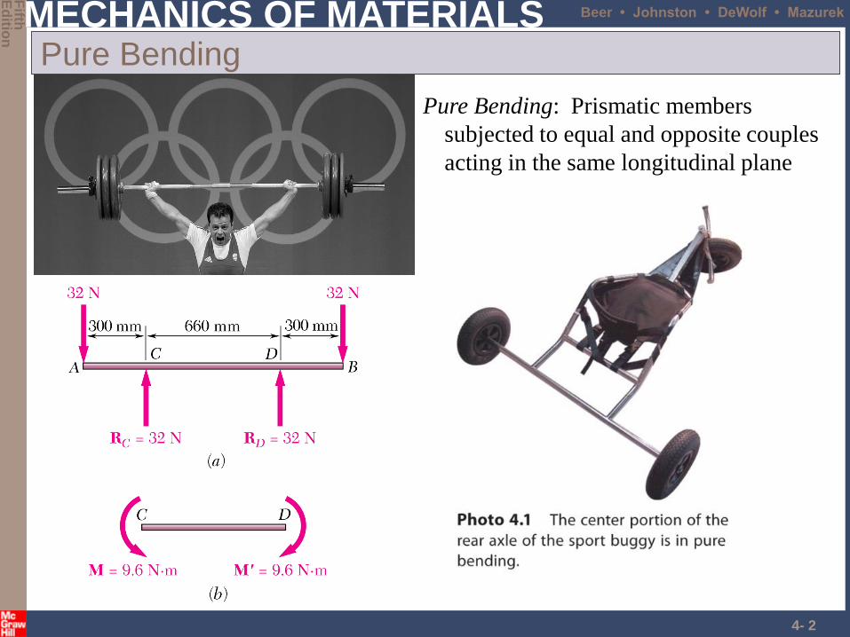
Pure Bending
Pure Bending: Prismatic members
subjected to equal and opposite couples
acting in the same longitudinal plane
MECHANICS OF MATERIALS
Fifth
Ed
ition
Beer • Johnston • DeWolf • Mazurek
4- 3
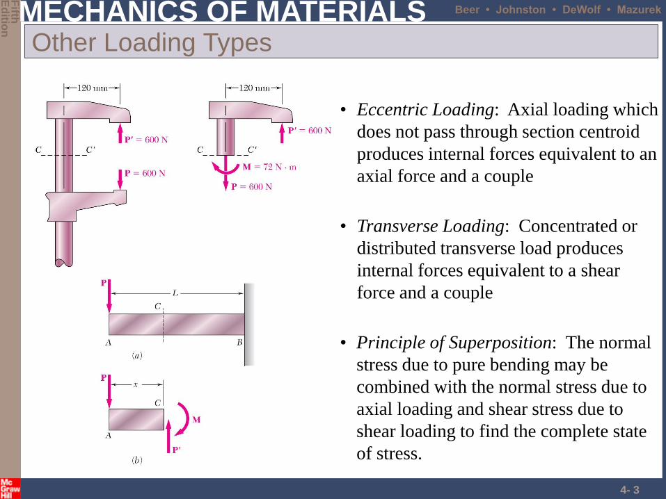
Other Loading Types
• Principle of Superposition: The normal
stress due to pure bending may be
combined with the normal stress due to
axial loading and shear stress due to
shear loading to find the complete state
of stress.
• Eccentric Loading: Axial loading which
does not pass through section centroid
produces internal forces equivalent to an
axial force and a couple
• Transverse Loading: Concentrated or
distributed transverse load produces
internal forces equivalent to a shear
force and a couple
MECHANICS OF MATERIALS
Fifth
Ed
ition
Beer • Johnston • DeWolf • Mazurek
4- 4
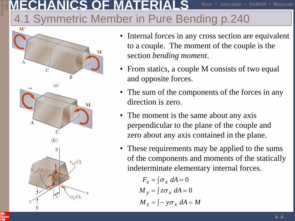
4.1 Symmetric Member in Pure Bending p.240
• From statics, a couple M consists of two equal
and opposite forces.
• The sum of the components of the forces in any
direction is zero.
• The moment is the same about any axis
perpendicular to the plane of the couple and
zero about any axis contained in the plane.
• Internal forces in any cross section are equivalent
to a couple. The moment of the couple is the
section bending moment.
MdAyM
dAzM
dAF
xz
xy
xx
0
0
• These requirements may be applied to the sums
of the components and moments of the statically
indeterminate elementary internal forces.
MECHANICS OF MATERIALS
Fifth
Ed
ition
Beer • Johnston • DeWolf • Mazurek
4- 5
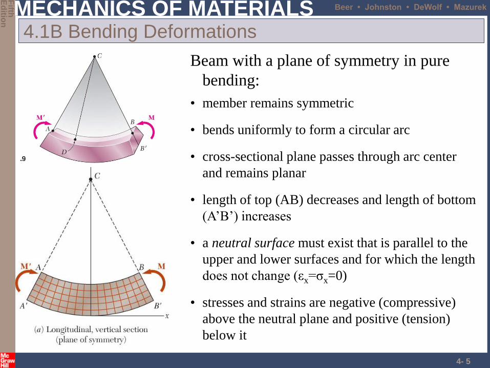
4.1B Bending Deformations
• bends uniformly to form a circular arc
• cross-sectional plane passes through arc center
and remains planar
• length of top (AB) decreases and length of bottom
(A’B’) increases
• a neutral surface must exist that is parallel to the
upper and lower surfaces and for which the length
does not change (εx=σx=0)
• stresses and strains are negative (compressive)
above the neutral plane and positive (tension)
below it
Beam with a plane of symmetry in pure
bending:
• member remains symmetric
MECHANICS OF MATERIALS
Fifth
Ed
ition
Beer • Johnston • DeWolf • Mazurek
4- 6
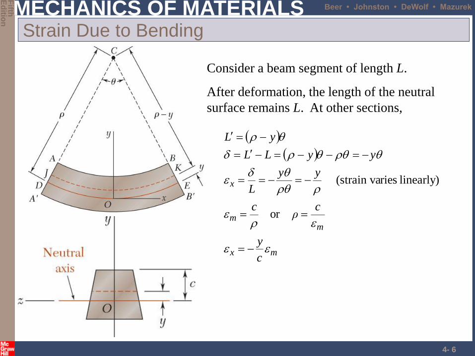
Strain Due to Bending
Consider a beam segment of length L.
After deformation, the length of the neutral
surface remains L. At other sections,
mx
mm
x
c
y
cρ
c
yy
L
yyLL
yL
or
linearly) ries(strain va
MECHANICS OF MATERIALS
Fifth
Ed
ition
Beer • Johnston • DeWolf • Mazurek
4- 7
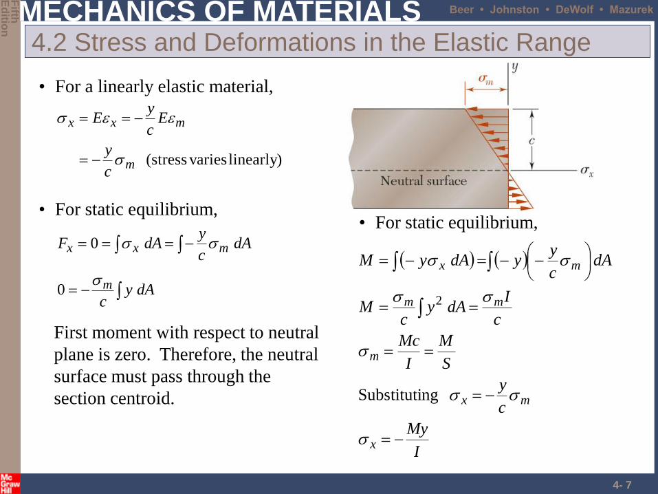
4.2 Stress and Deformations in the Elastic Range
• For a linearly elastic material,
• For static equilibrium,
dAyc
dAc
ydAF
m
mxx
0
0
First moment with respect to neutral
plane is zero. Therefore, the neutral
surface must pass through the
section centroid.
• For static equilibrium,
I
My
c
y
S
M
I
Mc
c
IdAy
cM
dAc
yydAyM
x
mx
m
mm
mx
ngSubstituti
2
linearly) varies(stressm
mxx
c
y
Ec
yE
MECHANICS OF MATERIALS
Fifth
Ed
ition
Beer • Johnston • DeWolf • Mazurek
4- 8
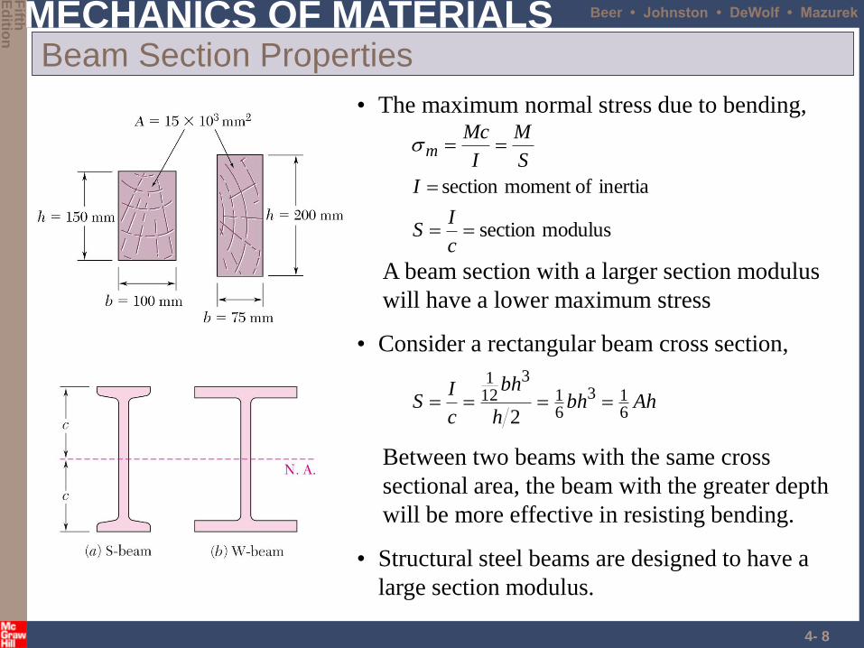
Beam Section Properties
• The maximum normal stress due to bending,
modulussection
inertia ofmoment section
c
IS
I
S
M
I
Mcm
A beam section with a larger section modulus
will have a lower maximum stress
• Consider a rectangular beam cross section,
Ahbhh
bh
c
IS
613
61
3121
2
Between two beams with the same cross
sectional area, the beam with the greater depth
will be more effective in resisting bending.
• Structural steel beams are designed to have a
large section modulus.
MECHANICS OF MATERIALS
Fifth
Ed
ition
Beer • Johnston • DeWolf • Mazurek
4- 9
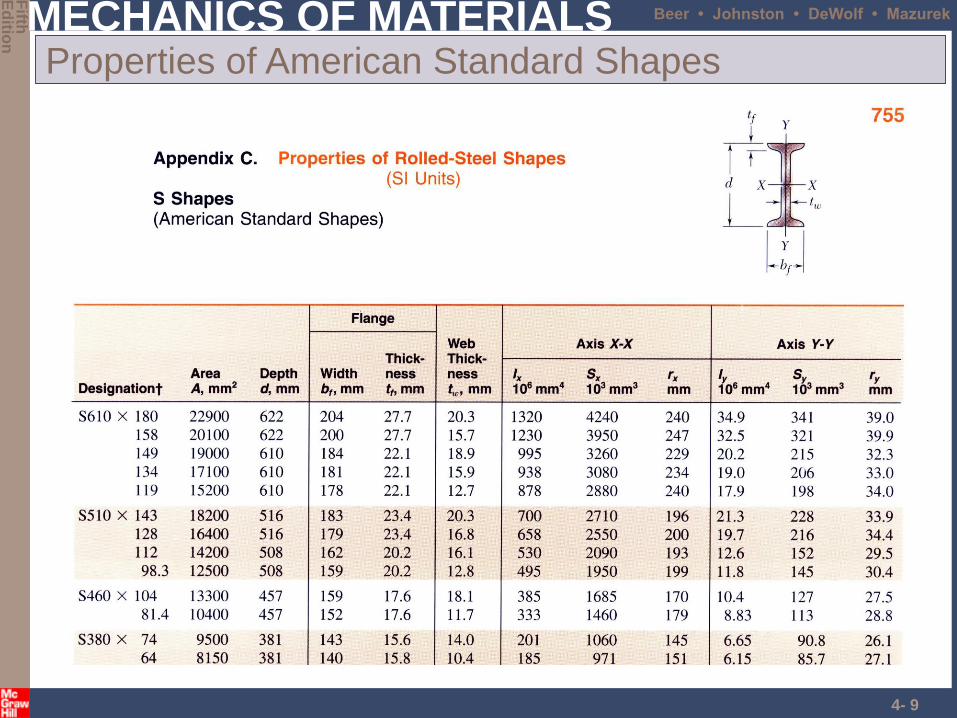
Properties of American Standard Shapes

MECHANICS OF MATERIALS
Fifth
Ed
ition
Beer • Johnston • DeWolf • Mazurek
4- 10
Deformations in a Transverse Cross Section
• Deformation due to bending moment M is
quantified by the curvature of the neutral surface
EI
M
I
Mc
EcEcc
mm
11
MECHANICS OF MATERIALS
Fifth
Ed
ition
Beer • Johnston • DeWolf • Mazurek
4- 11
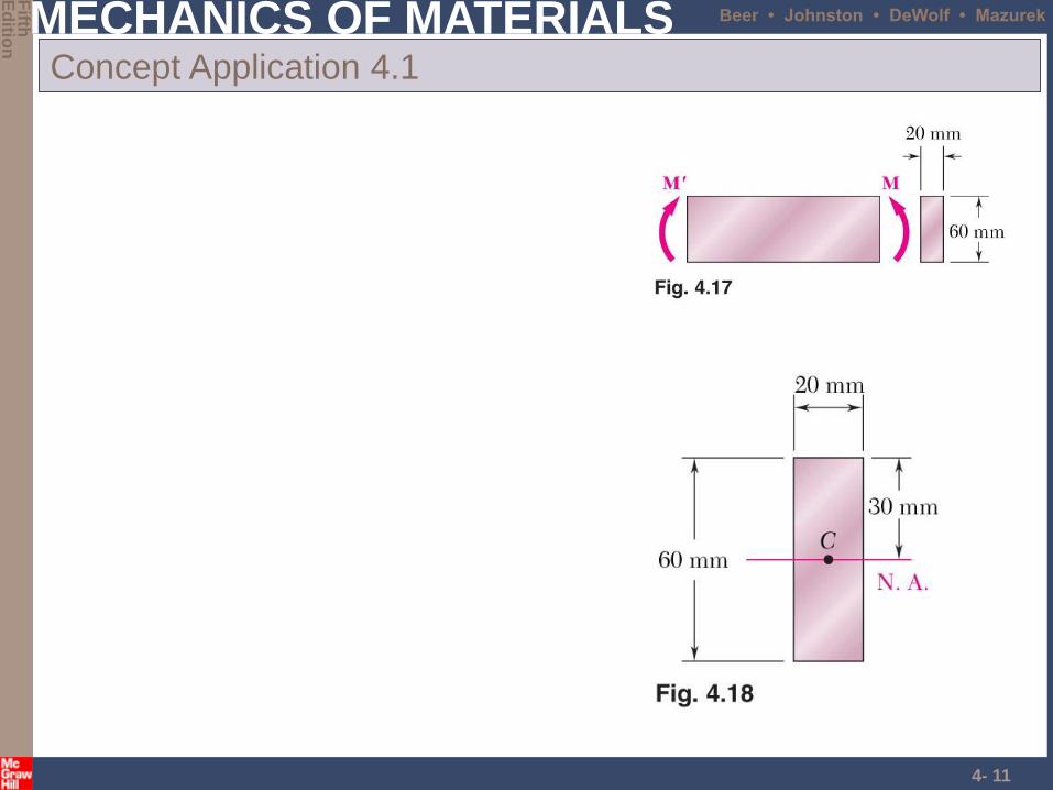
Concept Application 4.1
MECHANICS OF MATERIALS
Fifth
Ed
ition
Beer • Johnston • DeWolf • Mazurek
4- 12
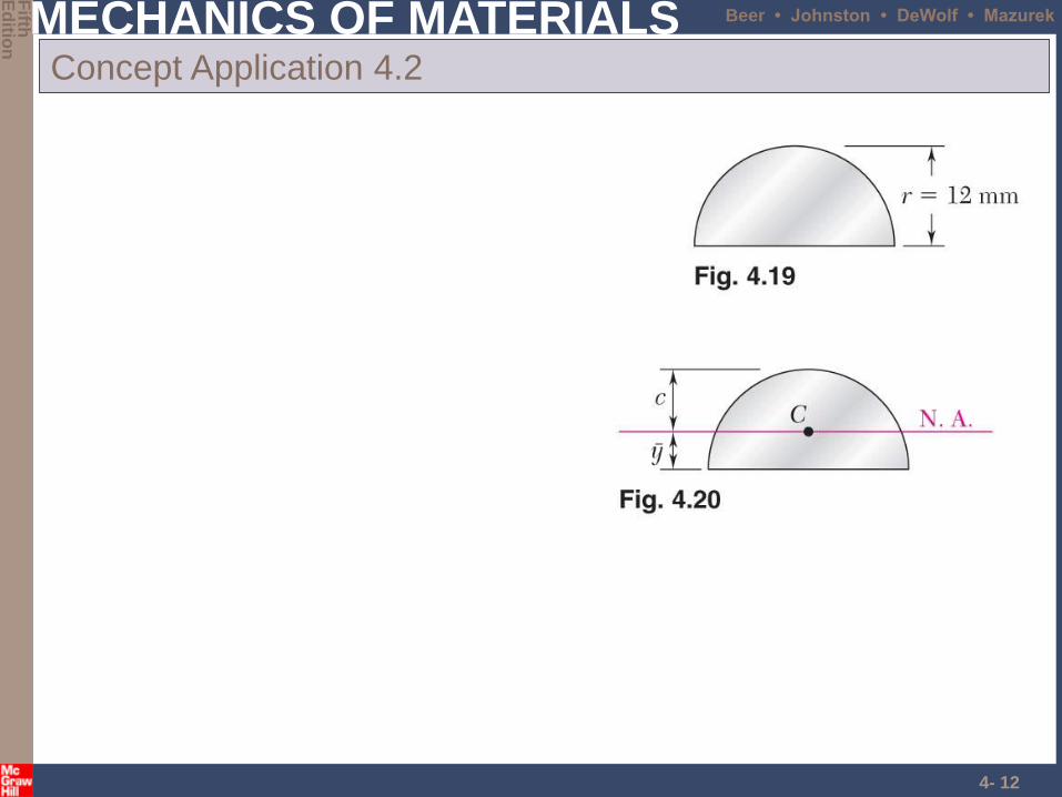
Concept Application 4.2
MECHANICS OF MATERIALS
Fifth
Ed
ition
Beer • Johnston • DeWolf • Mazurek
4- 13
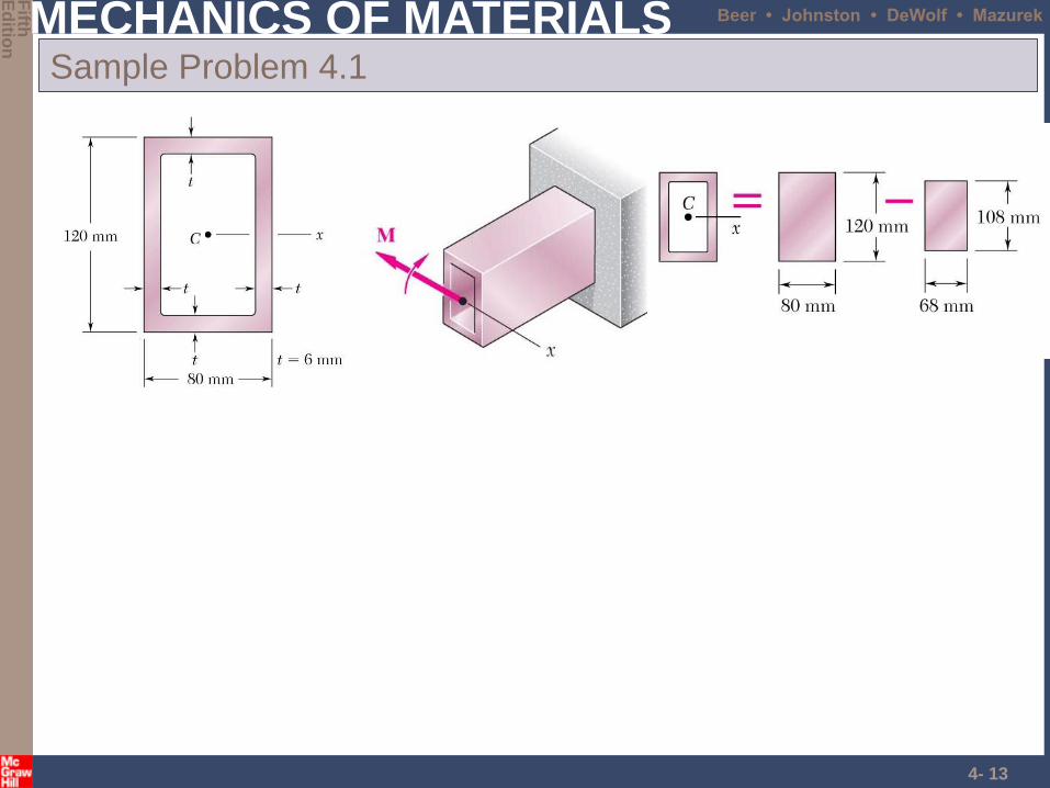
Sample Problem 4.1
MECHANICS OF MATERIALS
Fifth
Ed
ition
Beer • Johnston • DeWolf • Mazurek
4- 14
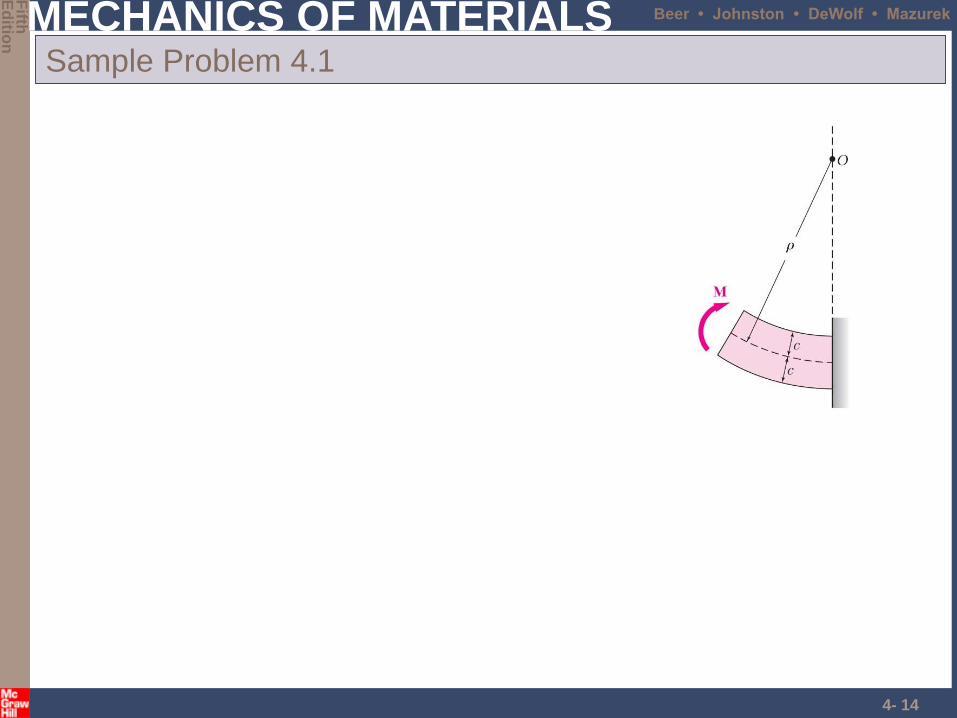
Sample Problem 4.1
MECHANICS OF MATERIALS
Fifth
Ed
ition
Beer • Johnston • DeWolf • Mazurek
4- 15
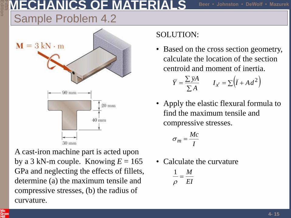
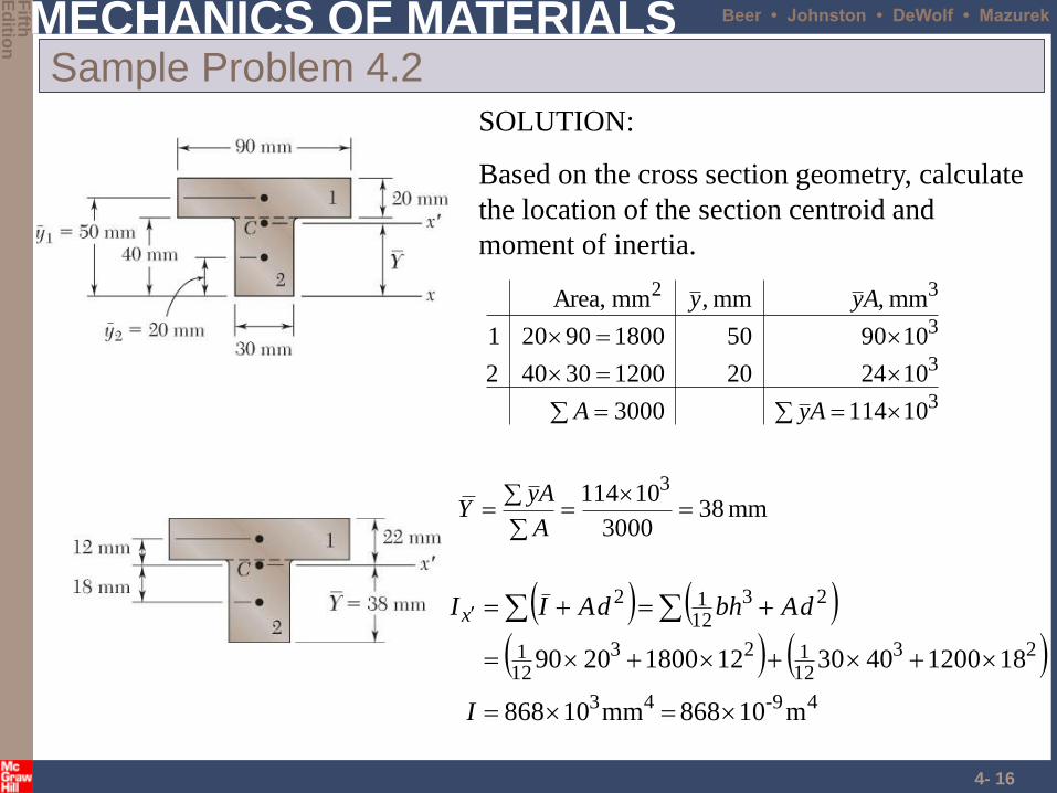
Sample Problem 4.2
SOLUTION:
• Based on the cross section geometry,
calculate the location of the section
centroid and moment of inertia.
2dAIIA
AyY x
• Apply the elastic flexural formula to
find the maximum tensile and
compressive stresses.
I
Mcm
• Calculate the curvature
EI
M
1
A cast-iron machine part is acted upon
by a 3 kN-m couple. Knowing E = 165
GPa and neglecting the effects of fillets,
determine (a) the maximum tensile and
compressive stresses, (b) the radius of
curvature.
MECHANICS OF MATERIALS
Fifth
Ed
ition
Beer • Johnston • DeWolf • Mazurek
4- 16
Sample Problem 4.2
SOLUTION:
Based on the cross section geometry, calculate
the location of the section centroid and
moment of inertia.
mm 383000
10114 3
A
AyY
3
3
3
32
101143000
104220120030402
109050180090201
mm ,mm ,mm Area,
AyA
Ayy
49-43
23
12123
121
23
1212
m10868 mm10868
18120040301218002090
I
dAbhdAIIx
MECHANICS OF MATERIALS
Fifth
Ed
ition
Beer • Johnston • DeWolf • Mazurek
4- 17
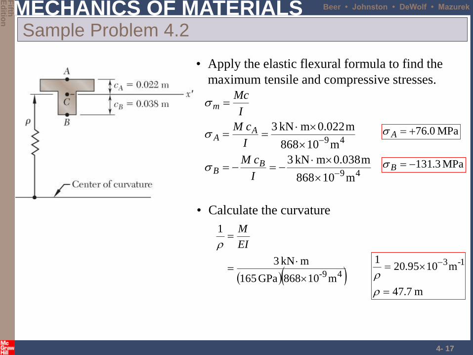
Sample Problem 4.2
• Apply the elastic flexural formula to find the
maximum tensile and compressive stresses.
49
49
m10868
m038.0mkN 3
m10868
m022.0mkN 3
I
cM
I
cM
I
Mc
BB
AA
m
MPa 0.76A
MPa 3.131B
• Calculate the curvature
49- m10868GPa 165
mkN 3
1
EI
M
m 7.47
m1095.201 1-3
MECHANICS OF MATERIALS
Fifth
Ed
ition
Beer • Johnston • DeWolf • Mazurek
4- 18
Problems
• Page 253
– 4-6
• Page 256
– 4-18
MECHANICS OF MATERIALS
Fifth
Ed
ition
Beer • Johnston • DeWolf • Mazurek
4- 19
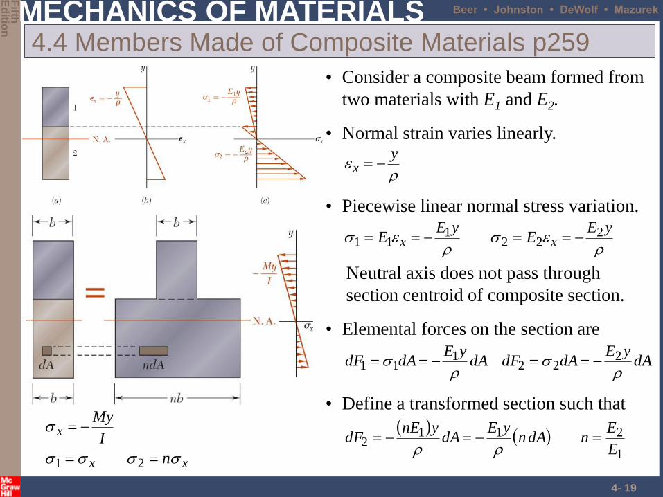
4.4 Members Made of Composite Materials p259
• Normal strain varies linearly.
yx
• Piecewise linear normal stress variation.
yEE
yEE xx
222
111
Neutral axis does not pass through
section centroid of composite section.
• Elemental forces on the section are
dAyE
dAdFdAyE
dAdF
222
111
• Consider a composite beam formed from
two materials with E1 and E2.
xx
x
n
I
My
21
1
2112
E
EndAn
yEdA
ynEdF
• Define a transformed section such that
MECHANICS OF MATERIALS
Fifth
Ed
ition
Beer • Johnston • DeWolf • Mazurek
4- 20
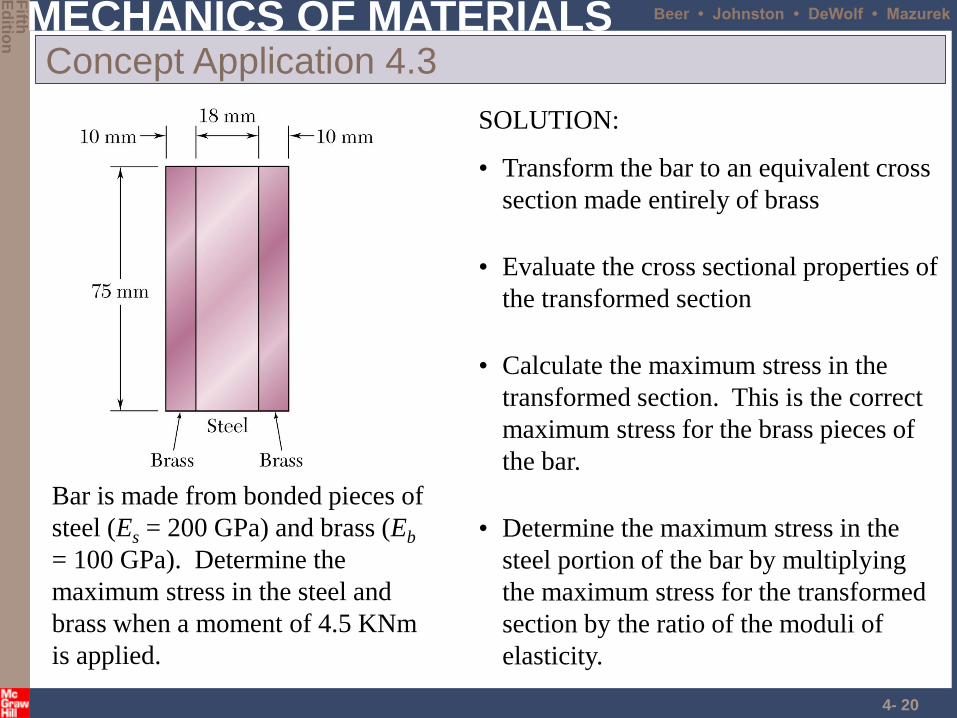
Concept Application 4.3
SOLUTION:
• Transform the bar to an equivalent cross
section made entirely of brass
• Evaluate the cross sectional properties of
the transformed section
• Calculate the maximum stress in the
transformed section. This is the correct
maximum stress for the brass pieces of
the bar.
• Determine the maximum stress in the
steel portion of the bar by multiplying
the maximum stress for the transformed
section by the ratio of the moduli of
elasticity.
Bar is made from bonded pieces of
steel (Es = 200 GPa) and brass (Eb
= 100 GPa). Determine the
maximum stress in the steel and
brass when a moment of 4.5 KNm
is applied.
MECHANICS OF MATERIALS
Fifth
Ed
ition
Beer • Johnston • DeWolf • Mazurek
4- 21
Concept Application 4.3
• Evaluate the transformed cross sectional properties
46
3
1213
121
mm 1096875.1
mm 75mm 56
hbI T
SOLUTION:
• Transform the bar to an equivalent cross section
made entirely of brass.
mm 56mm 10mm 182mm 10
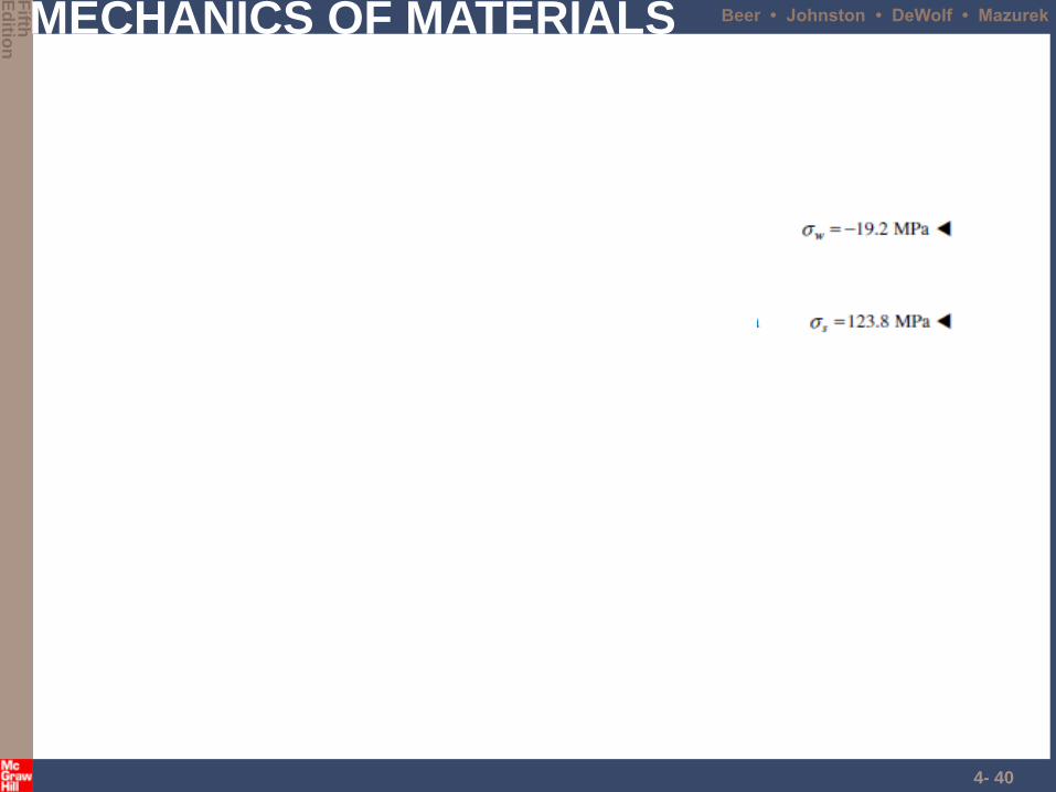
0.2GPa100
GPa200
T
b
s
b
E
En
• Calculate the maximum stresses
MPa 7.85
m 101.96875
m .03750Nm 450046-
I
Mcm
MPa 7.852max
max
ms
mb
n
MPa .4711
MPa 7.85
max
max
s
b
MECHANICS OF MATERIALS
Fifth
Ed
ition
Beer • Johnston • DeWolf • Mazurek
4- 22
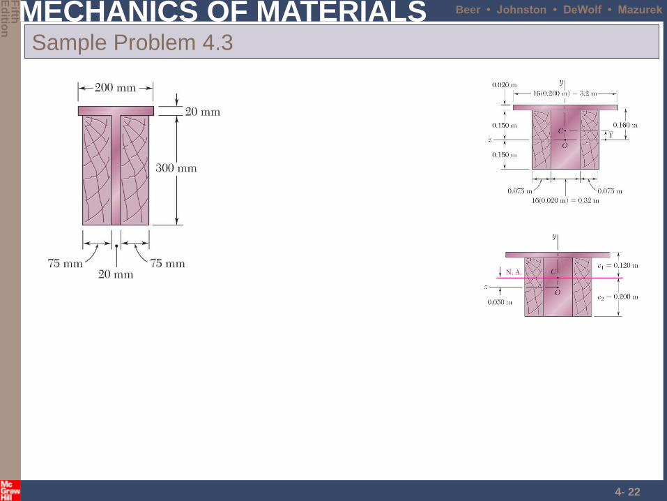
Sample Problem 4.3
MECHANICS OF MATERIALS
Fifth
Ed
ition
Beer • Johnston • DeWolf • Mazurek
4- 23
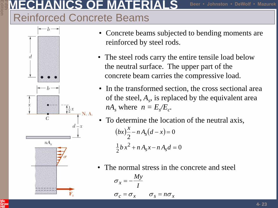
Reinforced Concrete Beams
• Concrete beams subjected to bending moments are
reinforced by steel rods.
• To determine the location of the neutral axis,
0
022
21
dAnxAnxb
xdAnx
bx
ss
s
• The steel rods carry the entire tensile load below
the neutral surface. The upper part of the
concrete beam carries the compressive load.
• In the transformed section, the cross sectional area
of the steel, As, is replaced by the equivalent area
nAs where n = Es/Ec.
• The normal stress in the concrete and steel
xsxc
x
n
I
My
MECHANICS OF MATERIALS
Fifth
Ed
ition
Beer • Johnston • DeWolf • Mazurek
4- 24
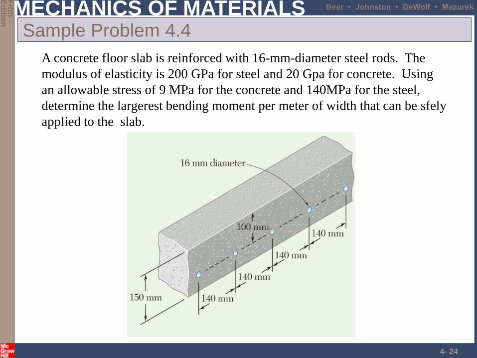
Sample Problem 4.4
A concrete floor slab is reinforced with 16-mm-diameter steel rods. The
modulus of elasticity is 200 GPa for steel and 20 Gpa for concrete. Using
an allowable stress of 9 MPa for the concrete and 140MPa for the steel,
determine the largerest bending moment per meter of width that can be sfely
applied to the slab.
MECHANICS OF MATERIALS
Fifth
Ed
ition
Beer • Johnston • DeWolf • Mazurek
4- 25
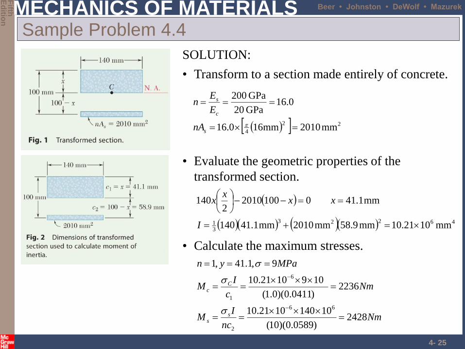
Sample Problem 4.4
• Evaluate the geometric properties of the
transformed section.
46223
31 mm1021.10mm9.58mm2010mm1.41140
mm1.41010020102
140
I
xxx
x
SOLUTION:
• Transform to a section made entirely of concrete.
22
4mm2010mm160.16
0.16GPa 02
GPa 002
s
c
s
nA
E
En
• Calculate the maximum stresses.
Nmnc
IM
Nmc
IM
MPayn
ss
Cc
2428)0589.0)(10(
101401010.21
2236)0411.0)(0.1(
1091021.10
9,1.41,1
66
2
6
1
MECHANICS OF MATERIALS
Fifth
Ed
ition
Beer • Johnston • DeWolf • Mazurek
4- 26
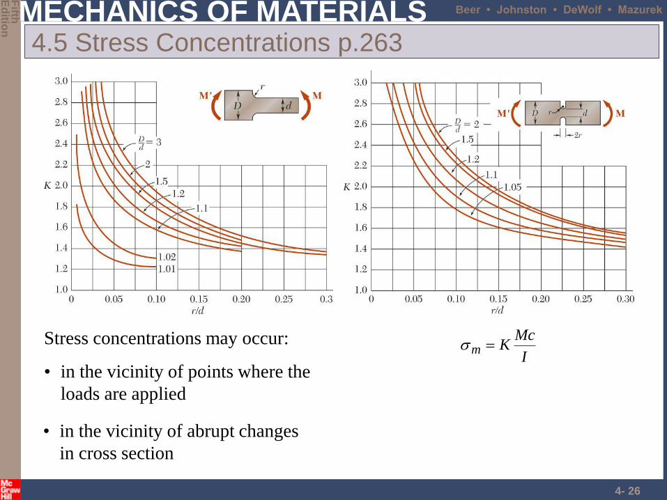
4.5 Stress Concentrations p.263
Stress concentrations may occur:
• in the vicinity of points where the
loads are applied
I
McKm
• in the vicinity of abrupt changes
in cross section
MECHANICS OF MATERIALS
Fifth
Ed
ition
Beer • Johnston • DeWolf • Mazurek
4- 27
Concept Application 4.4
MECHANICS OF MATERIALS
Fifth
Ed
ition
Beer • Johnston • DeWolf • Mazurek
4- 28
Problems
• Page 269
– 4-39, 4-47
MECHANICS OF MATERIALS
Fifth
Ed
ition
Beer • Johnston • DeWolf • Mazurek
4- 29
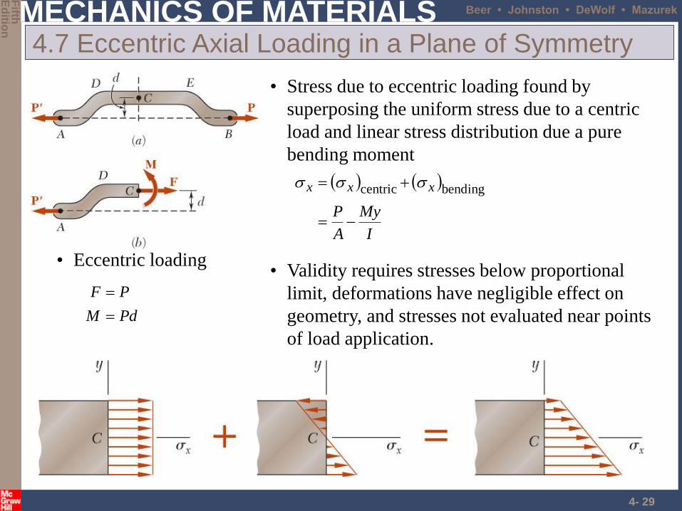
4.7 Eccentric Axial Loading in a Plane of Symmetry
• Validity requires stresses below proportional
limit, deformations have negligible effect on
geometry, and stresses not evaluated near points
of load application.
• Eccentric loading
PdM
PF
• Stress due to eccentric loading found by
superposing the uniform stress due to a centric
load and linear stress distribution due a pure
bending moment
I
My
A
P
xxx
bendingcentric
MECHANICS OF MATERIALS
Fifth
Ed
ition
Beer • Johnston • DeWolf • Mazurek
4- 30
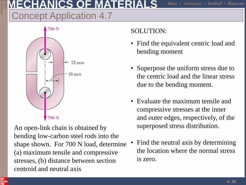
Concept Application 4.7
An open-link chain is obtained by
bending low-carbon steel rods into the
shape shown. For 700 N load, determine
(a) maximum tensile and compressive
stresses, (b) distance between section
centroid and neutral axis
SOLUTION:
• Find the equivalent centric load and
bending moment
• Superpose the uniform stress due to
the centric load and the linear stress
due to the bending moment.
• Evaluate the maximum tensile and
compressive stresses at the inner
and outer edges, respectively, of the
superposed stress distribution.
• Find the neutral axis by determining
the location where the normal stress
is zero.
MECHANICS OF MATERIALS
Fifth
Ed
ition
Beer • Johnston • DeWolf • Mazurek
4- 31
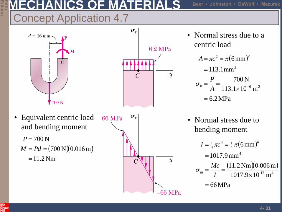
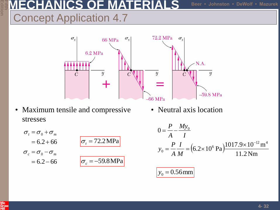
Concept Application 4.7
• Equivalent centric load
and bending moment
Nm2.11
m016.0N700
N700
PdM
P
MPa2.6
m101.113
N700
mm1.113
mm6
260
2
22
A
P
cA
• Normal stress due to a
centric load
MPa66
m109.1017
m006.0Nm2.11
mm9.1017
mm6
412-
4
4
414
41
I
Mc
cI
m
• Normal stress due to
bending moment
MECHANICS OF MATERIALS
Fifth
Ed
ition
Beer • Johnston • DeWolf • Mazurek
4- 32
Concept Application 4.7
• Maximum tensile and compressive
stresses
662.6
662.6
0
0
mc
mt
MPa2.72t
MPa8.59c
• Neutral axis location
Nm.211
m109.1017Pa102.6
0
4126
0
0
M
I
A
Py
I
My
A
P
mm56.00 y
MECHANICS OF MATERIALS
Fifth
Ed
ition
Beer • Johnston • DeWolf • Mazurek
4- 33
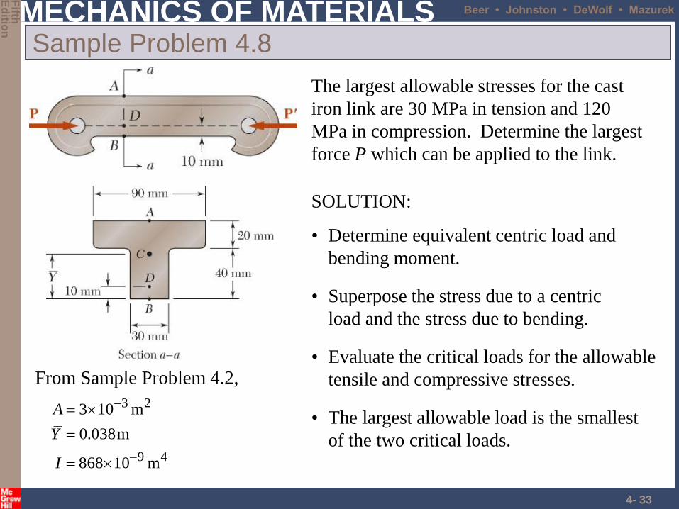
Sample Problem 4.8
The largest allowable stresses for the cast
iron link are 30 MPa in tension and 120
MPa in compression. Determine the largest
force P which can be applied to the link.
SOLUTION:
• Determine equivalent centric load and
bending moment.
• Evaluate the critical loads for the allowable
tensile and compressive stresses.
• The largest allowable load is the smallest
of the two critical loads.
From Sample Problem 4.2,
49
23
m10868
m038.0
m103
I
Y
A
• Superpose the stress due to a centric
load and the stress due to bending.
MECHANICS OF MATERIALS
Fifth
Ed
ition
Beer • Johnston • DeWolf • Mazurek
4- 34
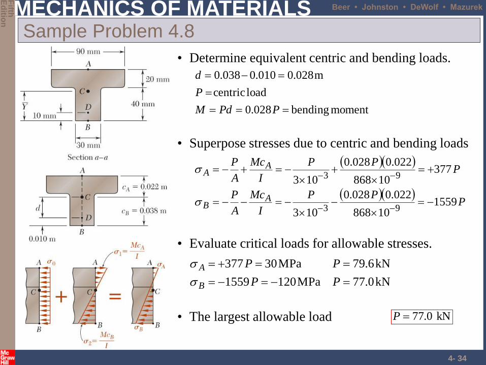
Sample Problem 4.8
• Determine equivalent centric and bending loads.
moment bending 028.0
load centric
m028.0010.0038.0
PPdM
P
d
• Evaluate critical loads for allowable stresses.
kN0.77MPa1201559
kN6.79MPa30377
PP
PP
B
A
kN 0.77P• The largest allowable load
• Superpose stresses due to centric and bending loads
P
PP
I
Mc
A
P
PPP
I
Mc
A
P
AB
AA
155910868
022.0028.0
103
37710868
022.0028.0
103
93
93
MECHANICS OF MATERIALS
Fifth
Ed
ition
Beer • Johnston • DeWolf • Mazurek
4- 35
Problems
• Page 297
– 4-106
MECHANICS OF MATERIALS
Fifth
Ed
ition
Beer • Johnston • DeWolf • Mazurek
4- 36
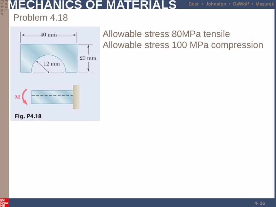
Problem 4.18
Allowable stress 80MPa tensile
Allowable stress 100 MPa compression
MECHANICS OF MATERIALS
Fifth
Ed
ition
Beer • Johnston • DeWolf • Mazurek
4- 37
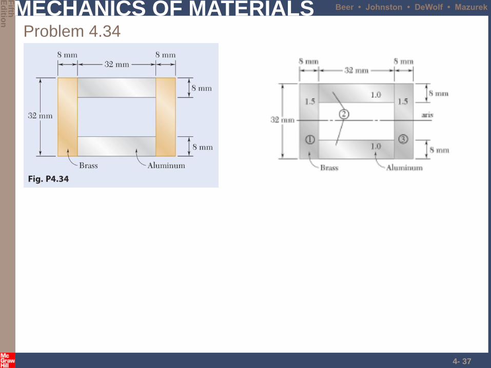
Problem 4.34
MECHANICS OF MATERIALS
Fifth
Ed
ition
Beer • Johnston • DeWolf • Mazurek
4- 38
MECHANICS OF MATERIALS
Fifth
Ed
ition
Beer • Johnston • DeWolf • Mazurek
4- 39
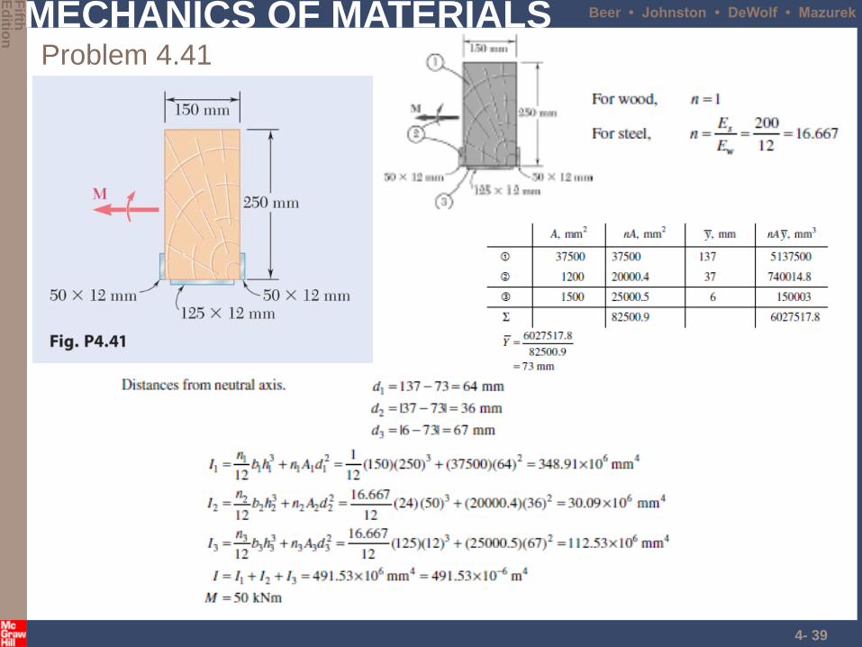
Problem 4.41
MECHANICS OF MATERIALS
Fifth
Ed
ition
Beer • Johnston • DeWolf • Mazurek
4- 40
Related Documents