3/13/2014 1 PUMPS TECHNOLOGY GENERA L COURSE FOR ENGI NEERS For more PPT presentations: ebooks.com - http://www.y

Welcome message from author
This document is posted to help you gain knowledge. Please leave a comment to let me know what you think about it! Share it to your friends and learn new things together.
Transcript
8/12/2019 Pumps Technology2
http://slidepdf.com/reader/full/pumps-technology2 1/71
3/13/2014 1
PUMPS TECHNOLOGY
GENERA L COURSE FOR ENGINEERS
For more PPT presentations: ebooks.com-http://www.y

8/12/2019 Pumps Technology2
http://slidepdf.com/reader/full/pumps-technology2 2/71
3/13/2014 2
INTRODUCTION
PUMPSDEFINATION
PUMPS HISTORYPUMPS
APPLICATIONS
PUMPSTERMINOLGY
8/12/2019 Pumps Technology2
http://slidepdf.com/reader/full/pumps-technology2 3/71
3/13/2014 3
MAIN TOPICS
PUMPS CLASSIFICATIONPUMPS APPLICATION
MAJOR COMPONENTS OFCENERIFUGAL & RECIPROCATINGPUMPS
CALCULATION & PERFORMANCEOPERATION & TROUBLESHOOTING

8/12/2019 Pumps Technology2
http://slidepdf.com/reader/full/pumps-technology2 4/71
3/13/2014 4
PUMPS
Pumps are machinesthat are used to moveliquids from one placeto anther throughpipelines.Pumps handle allkinds of liquids.
Pumping rates canvary from a fewgallons to amillion/day
8/12/2019 Pumps Technology2
http://slidepdf.com/reader/full/pumps-technology2 5/71
3/13/2014 5
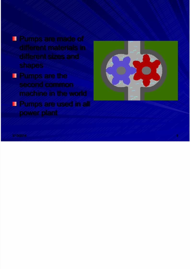
Pumps are made ofdifferent materials indifferent sizes and
shapesPumps are thesecond commonmachine in the worldPumps are used in allpower plant

8/12/2019 Pumps Technology2
http://slidepdf.com/reader/full/pumps-technology2 6/71
3/13/2014 6
Pumps applications
Examples of pumpsapplication in powerplants:
Boiler circulationFeed waterFuel oilChemical FeedCondensateCirculation waterVacuum
8/12/2019 Pumps Technology2
http://slidepdf.com/reader/full/pumps-technology2 7/71
3/13/2014 7
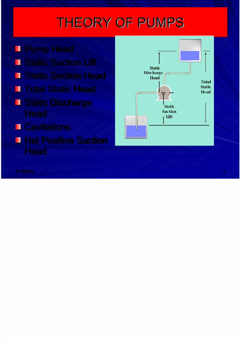
THEORY OF PUMPS
Pump HeadStatic Suction LiftStatic Section HeadTotal Static HeadStatic DischargeHead
CavitationsNet Positive SuctionHead
8/12/2019 Pumps Technology2
http://slidepdf.com/reader/full/pumps-technology2 8/71
3/13/2014 8
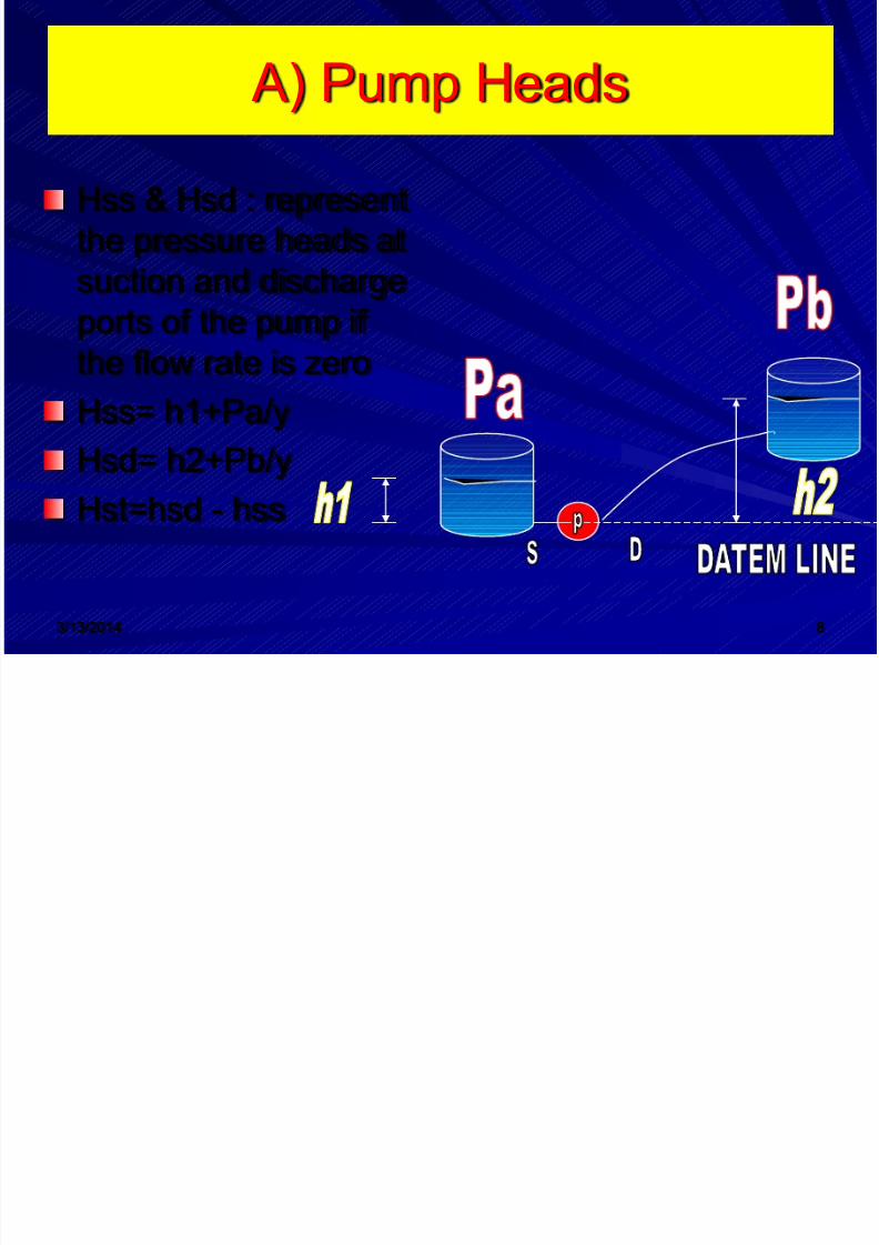
A) Pump Heads
Hss & Hsd : representthe pressure heads atsuction and dischargeports of the pump ifthe flow rate is zeroHss= h1+Pa/y
Hsd= h2+Pb/yHst=hsd - hss

8/12/2019 Pumps Technology2
http://slidepdf.com/reader/full/pumps-technology2 9/71
3/13/2014 9
PUMPS
TERMES
Fig. a Suction Lift – Showing StaticHeads in aPumping SystemWhere the Pumpis Located Abovethe SuctionTank. (StaticSuction Head)

8/12/2019 Pumps Technology2
http://slidepdf.com/reader/full/pumps-technology2 10/71
3/13/2014 10
PUMPSTERMS
Fig. b SuctionHead – ShowingStatic Heads in aPumping SystemWhere the Pumpis Located Belowthe Suction Tank.(Static SuctionHead)

8/12/2019 Pumps Technology2
http://slidepdf.com/reader/full/pumps-technology2 11/71
3/13/2014 11
Suction Head
Suction HeadA Suction Head existswhen the liquid is takenfrom an open toatmosphere tank wherethe liquid level is abovethe centerline of thepump suction,
commonly known as aFlooded Suction.
8/12/2019 Pumps Technology2
http://slidepdf.com/reader/full/pumps-technology2 12/71
3/13/2014 12
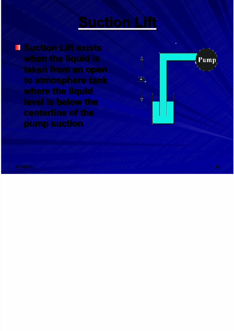
Suction Lift
Suction Lift existswhen the liquid istaken from an open
to atmosphere tankwhere the liquidlevel is below thecenterline of the
pump suction

8/12/2019 Pumps Technology2
http://slidepdf.com/reader/full/pumps-technology2 13/71
3/13/2014 13
Pump Heads
Pump suction head (hs)Hs represents the pressurehead at the pump suctionnozzle
Hs= Pa/y+h1-v2/2g-hLshL=f(L/D)v2/2g
F=friction factor
D=diameterV=velocityL= length of pipe up to the pointrequired
8/12/2019 Pumps Technology2
http://slidepdf.com/reader/full/pumps-technology2 14/71
3/13/2014 14
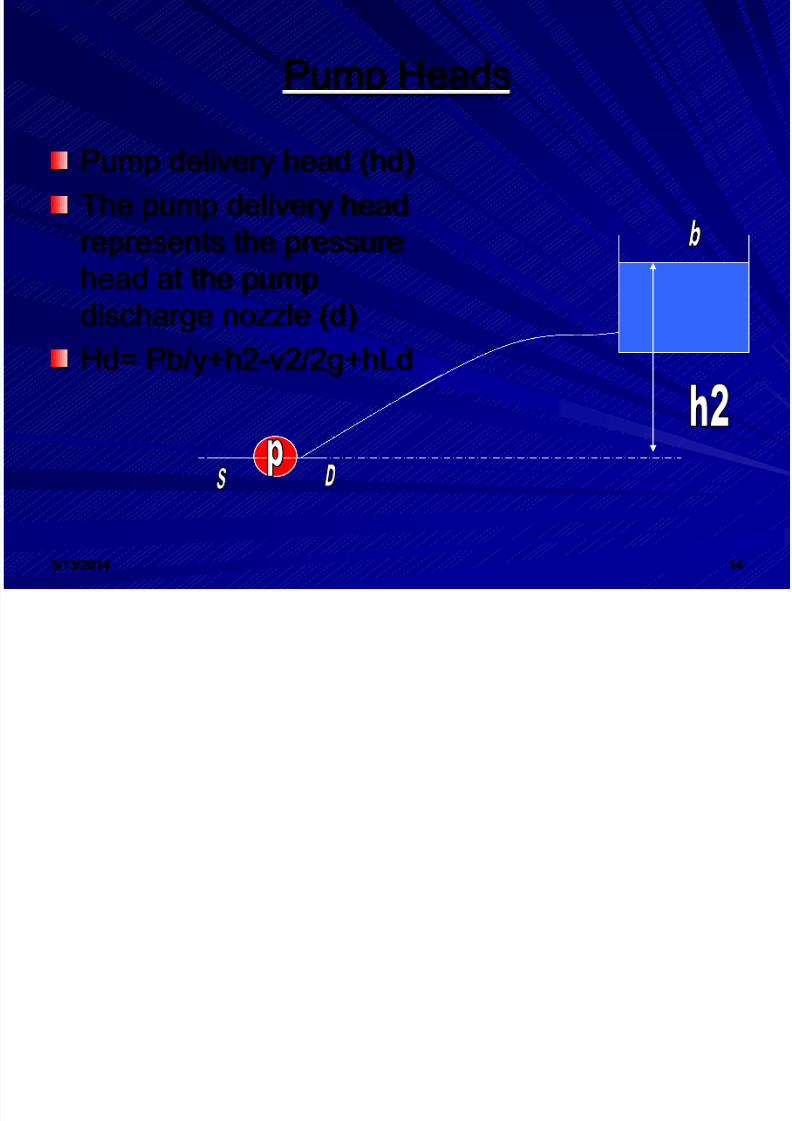
Pump Heads
Pump delivery head (hd)The pump delivery headrepresents the pressure
head at the pumpdischarge nozzle (d)Hd= Pb/y+h2-v2/2g+hLd
8/12/2019 Pumps Technology2
http://slidepdf.com/reader/full/pumps-technology2 15/71
3/13/2014 15
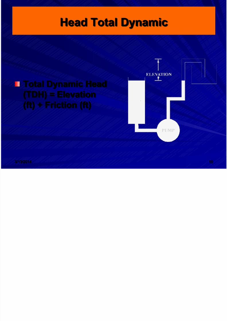
Head Total Dynamic
Total Dynamic Head(TDH) = Elevation(ft) + Friction (ft)
8/12/2019 Pumps Technology2
http://slidepdf.com/reader/full/pumps-technology2 16/71
3/13/2014 16
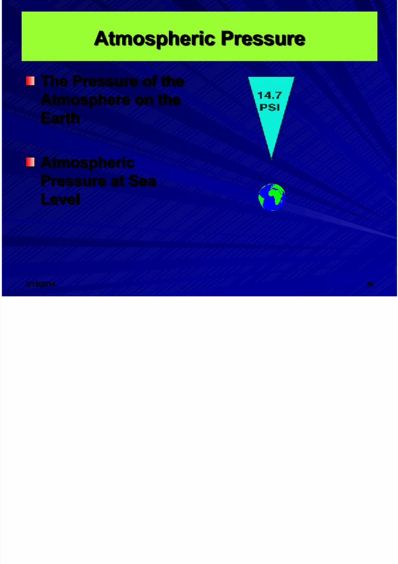
Atmospheric Pressure
The Pressure of theAtmosphere on theEarth
AtmosphericPressure at SeaLevel

8/12/2019 Pumps Technology2
http://slidepdf.com/reader/full/pumps-technology2 17/71
3/13/2014 17
Absolute Pressure
Absolute Pressure isthe sum of the availableatmospheric pressureand the gage pressurein the pumping systemAbsolute Pressure(PSIA) = GaugePressure +Atmospheric PressureAbsolute Pressure =150 PSIG (GaugePressure) + 14.7 PSI(Atmospheric Pressure)= 164.7 PSIA
8/12/2019 Pumps Technology2
http://slidepdf.com/reader/full/pumps-technology2 18/71
3/13/2014 18
Pump capacity
Capacity (Q) is normally expressed in gallonsper minute (gpm). Since liquids are essentiallyincompressible, there is a direct relationshipbetween the capacity in a pipe and the velocityof flow. This relationship is as follows:Q=A*V
Where
A = area of pipe or conduit in square feet.V = velocity of flow in feet per second.

8/12/2019 Pumps Technology2
http://slidepdf.com/reader/full/pumps-technology2 19/71
3/13/2014 19
PUMPS CLASSIFICATION
Dynamic pump
Displacement
8/12/2019 Pumps Technology2
http://slidepdf.com/reader/full/pumps-technology2 20/71
3/13/2014 20
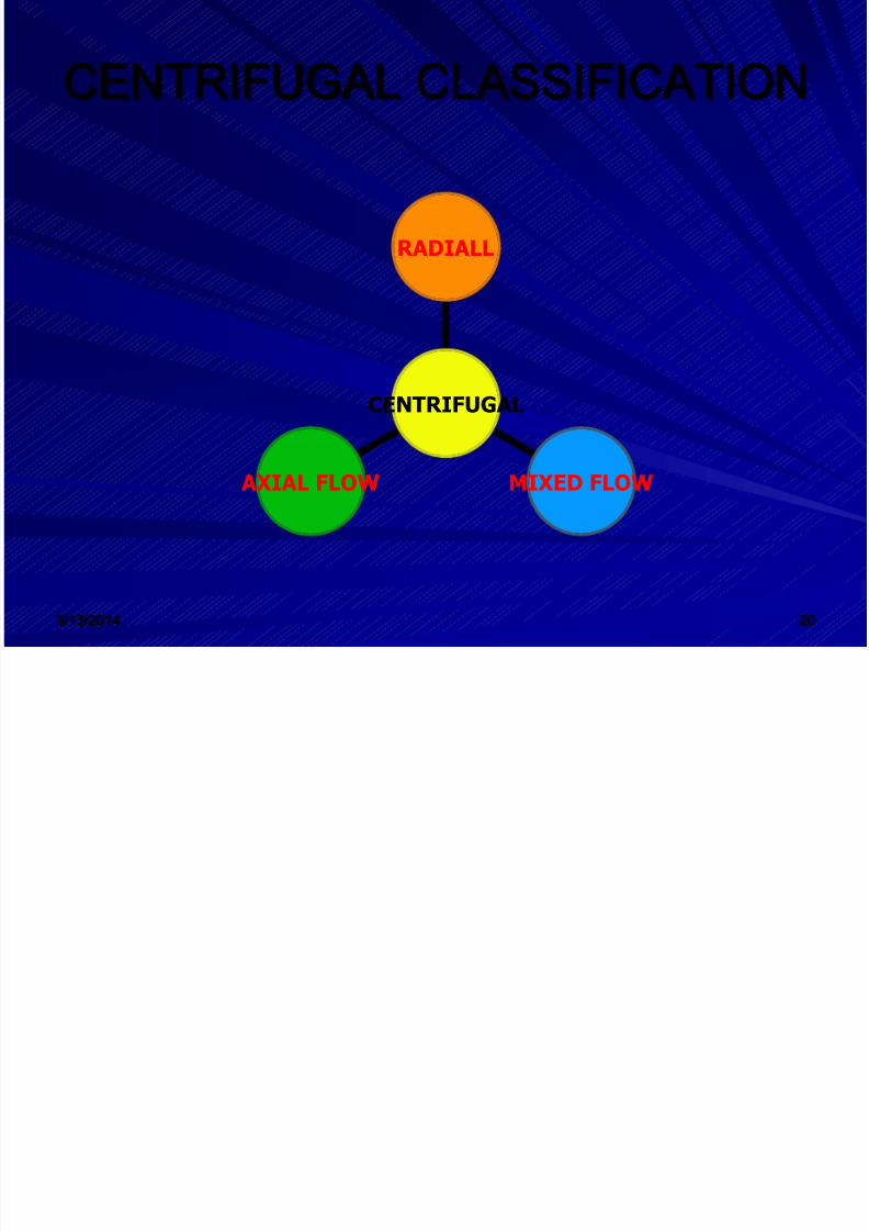
CENTRIFUGAL CLASSIFICATION
AXIAL FLOW MIXED FLOW
RADIALL
CENTRIFUGAL
8/12/2019 Pumps Technology2
http://slidepdf.com/reader/full/pumps-technology2 21/71

8/12/2019 Pumps Technology2
http://slidepdf.com/reader/full/pumps-technology2 22/71
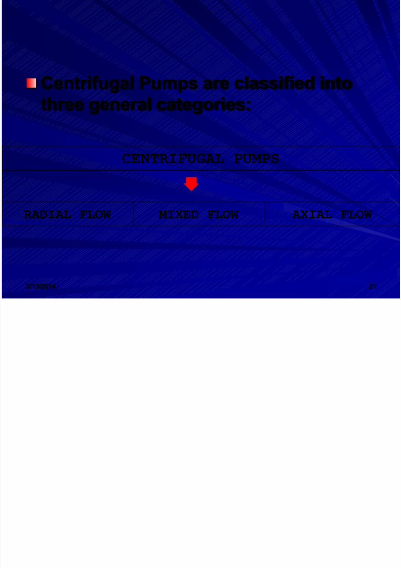
3/13/2014 22
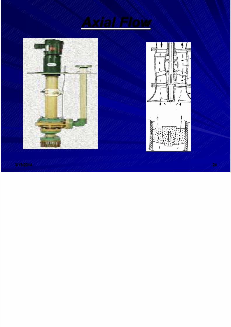
Axial Flow - a centrifugal pump in which thepressure is developed by the propelling orlifting action of the vanes of the impeller onthe liquid.
Radial Flow - a centrifugal pump in which thepressure is developed wholly by centrifugalforce.
Mixed Flow - a centrifugal pump in which thepressure is developed partly by centrifugalforce and partly by the lift of the vanes of theimpeller on the liquid.
8/12/2019 Pumps Technology2
http://slidepdf.com/reader/full/pumps-technology2 23/71
3/13/2014 23
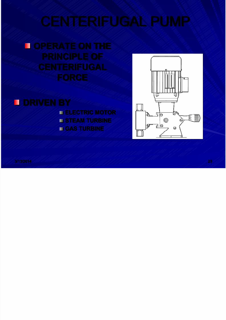
CENTERIFUGAL PUMP
OPERATE ON THEPRINCIPLE OF
CENTERIFUGAL
FORCE
DRIVEN BYELECTRIC MOTOR
STEAM TURBINEGAS TURBINE
8/12/2019 Pumps Technology2
http://slidepdf.com/reader/full/pumps-technology2 24/71
3/13/2014 24
A xial Flow
8/12/2019 Pumps Technology2
http://slidepdf.com/reader/full/pumps-technology2 25/71
3/13/2014 25
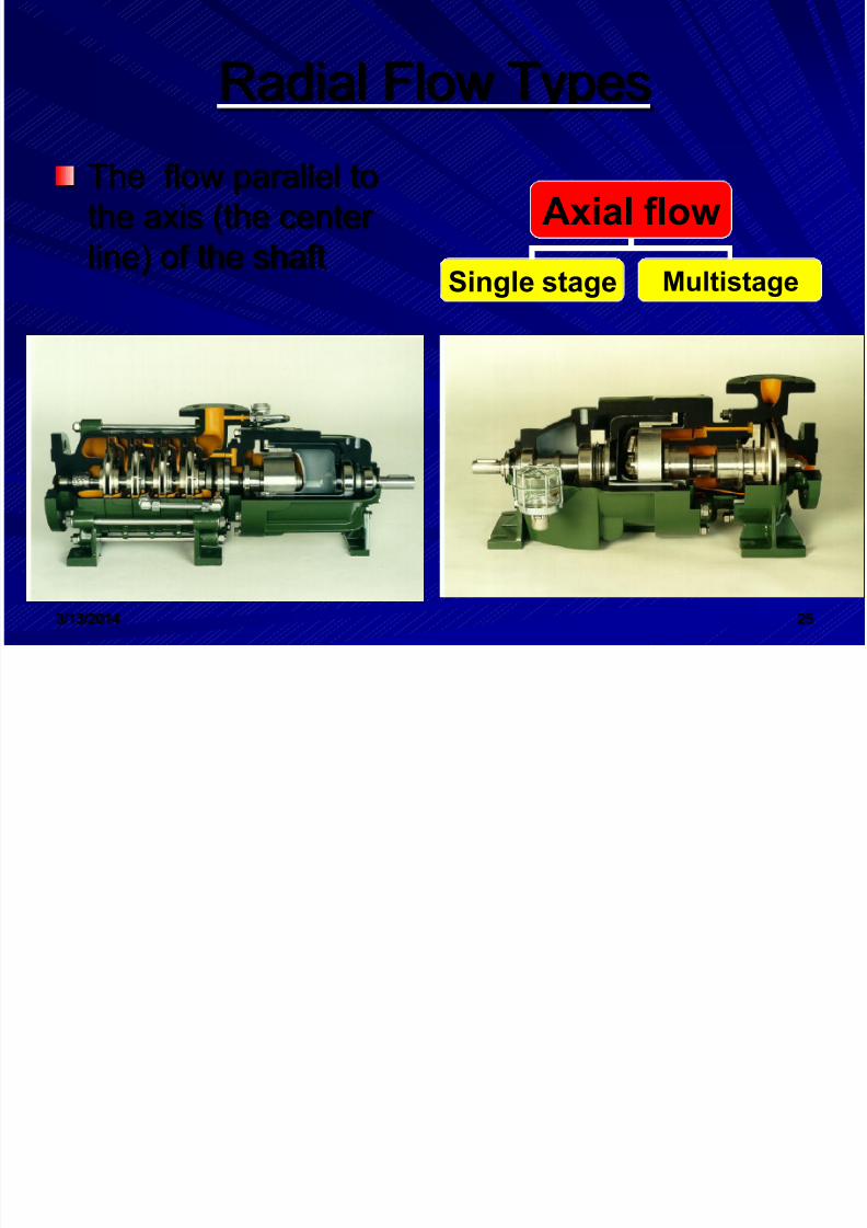
Radial Flow Types
The flow parallel tothe axis (the centerline) of the shaft
Axial flow
Single stage Multistage
8/12/2019 Pumps Technology2
http://slidepdf.com/reader/full/pumps-technology2 26/71
3/13/2014 26
AXIAL FLOW
Axial flow pumps are propeller pumpThe arrangement of the pump is usuallyvertical
Ability to operate at high speedLift capacity, discharge and the head arelowThere are to type: single stage &multistage

8/12/2019 Pumps Technology2
http://slidepdf.com/reader/full/pumps-technology2 27/71
3/13/2014 27
RADIAL FLOW
Flow at 9 0 angle tothe center line of theshaft
8/12/2019 Pumps Technology2
http://slidepdf.com/reader/full/pumps-technology2 28/71
3/13/2014 28
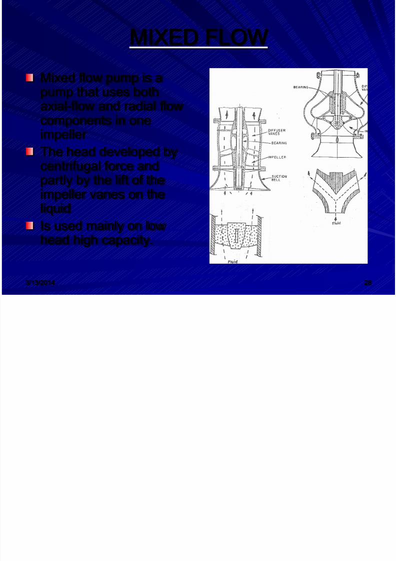
MIXED FLOW
Mixed flow pump is apump that uses bothaxial-flow and radial flowcomponents in one
impellerThe head developed bycentrifugal force andpartly by the lift of theimpeller vanes on the
liquidIs used mainly on lowhead high capacity.

8/12/2019 Pumps Technology2
http://slidepdf.com/reader/full/pumps-technology2 29/71
3/13/2014 29
MAJOR COMPONENTS OFCENTERIFUGAL PUMP
SUCTION INLETIMPELLERSHAFTCASING(HOUSING)DISCHARGEOUTLET
BEARINGSSEALS

8/12/2019 Pumps Technology2
http://slidepdf.com/reader/full/pumps-technology2 30/71
3/13/2014 30
Centrifugal Pump Components
The two maincomponents of acentrifugal pump arethe impeller and thevolute .The impeller producesliquid velocity and thevolute forces the liquid
to discharge from thepump convertingvelocity to pressure.

8/12/2019 Pumps Technology2
http://slidepdf.com/reader/full/pumps-technology2 31/71
3/13/2014 31
CENTRIFUGAL PUMP

8/12/2019 Pumps Technology2
http://slidepdf.com/reader/full/pumps-technology2 32/71
3/13/2014 32
CENTERIFUGAL PUMPS

8/12/2019 Pumps Technology2
http://slidepdf.com/reader/full/pumps-technology2 33/71
3/13/2014 33
1. SUCTION INLET
Liquid enter the pump through the suctionThe side of flow entering is calledUPSTREAM
The discharge side is called theDOWNSTREAMThe pipeline that carries the liquid isbolted or screwed the suction flange

8/12/2019 Pumps Technology2
http://slidepdf.com/reader/full/pumps-technology2 34/71
3/13/2014 34
1)SUCTION INLET
8/12/2019 Pumps Technology2
http://slidepdf.com/reader/full/pumps-technology2 35/71
3/13/2014 35
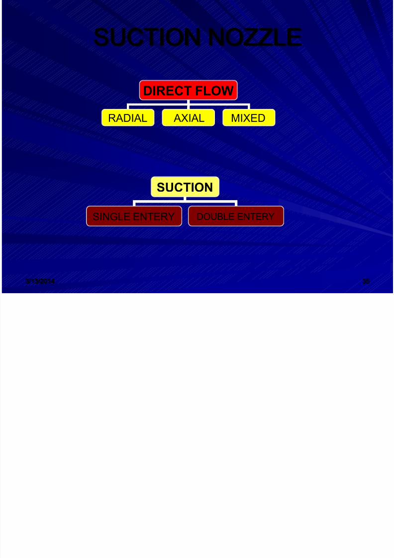
SUCTION NOZZLE
DIRECT FLOW
RADIAL AXIAL MIXED
SUCTION
SINGLE ENTERY DOUBLE ENTERY
8/12/2019 Pumps Technology2
http://slidepdf.com/reader/full/pumps-technology2 36/71
3/13/2014 36
2. IMPELLER & SHAFT
Impeller is the main part of a centrifugalpump.It move the liquid through the pumpIt is vary considerably in designIt can be classified according to specificspeed
8/12/2019 Pumps Technology2
http://slidepdf.com/reader/full/pumps-technology2 37/71
3/13/2014 37
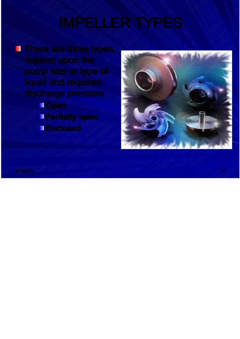
IMPELLER TYPES
There are three types,depend upon thepump size or type of
liquid and requireddischarge pressure.OpenPartially open
Enclosed

8/12/2019 Pumps Technology2
http://slidepdf.com/reader/full/pumps-technology2 38/71
8/12/2019 Pumps Technology2
http://slidepdf.com/reader/full/pumps-technology2 39/71
3/13/2014 39
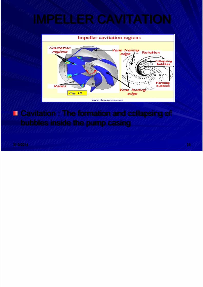
IMPELLER CAVITATION
Cavitation : The formation and collapsing of
bubbles inside the pump casing
8/12/2019 Pumps Technology2
http://slidepdf.com/reader/full/pumps-technology2 40/71
3/13/2014 40
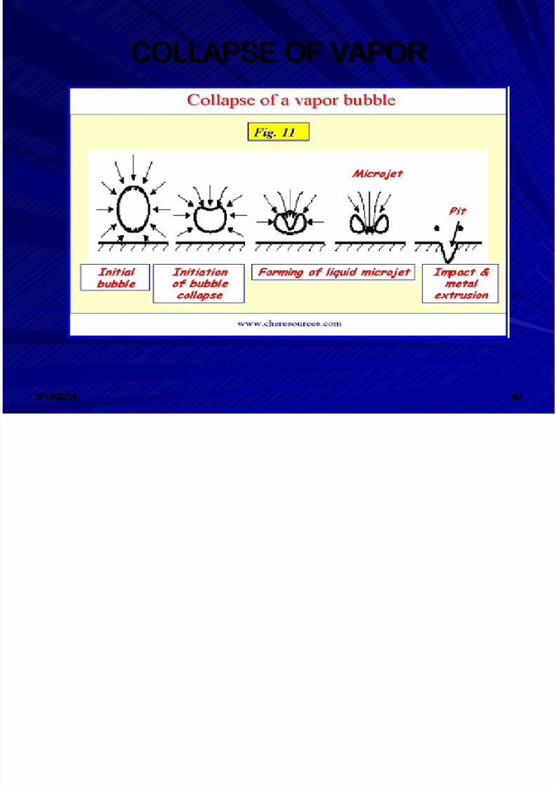
COLLAPSE OF VAPOR

8/12/2019 Pumps Technology2
http://slidepdf.com/reader/full/pumps-technology2 41/71

8/12/2019 Pumps Technology2
http://slidepdf.com/reader/full/pumps-technology2 42/71
3/13/2014 42
3. PUMP CASING
Centrifugal pump casing (Housing)encloses the rotating partsThe suction and discharge nozzles areusually in the lower casingThe upper have can be easily lifted forinspectionThere are many types of casing, ex.Volute and split.
8/12/2019 Pumps Technology2
http://slidepdf.com/reader/full/pumps-technology2 43/71
3/13/2014 43
4. DISCHARGE OUTLET
The liquid leave the pump under pressurethrough the discharge outletThe discharge outlet is the downstreamside of the pumpThe discharge flange is located at thelarge end of the volute.
8/12/2019 Pumps Technology2
http://slidepdf.com/reader/full/pumps-technology2 44/71

8/12/2019 Pumps Technology2
http://slidepdf.com/reader/full/pumps-technology2 45/71
3/13/2014 45
Wearing Rings
Centrifugal pumps contain rotating impellerswithin stationary pump casings. To allow theimpeller to rotate freely within the pump casing,
a small clearance is designed to be maintainedbetween the impeller and the pump casing. Tomaximize the efficiency of a centrifugal pump, itis necessary to minimize the amount of liquid
leaking through this clearance from the highpressure or discharge side of the pump back tothe low pressure or suction side.
8/12/2019 Pumps Technology2
http://slidepdf.com/reader/full/pumps-technology2 46/71
3/13/2014 46
Some wear or erosion will occur at the pointwhere the impeller and the pump casingnearly come into contact This wear is dueto the erosion caused by liquid leaking
through this tight clearance andother causes. As wear occurs,the clearances becomelarger and the rate of leakage increases.
Eventually, the leakage could becomeunacceptably large and maintenance would berequired on the pump. To minimize the cost ofpump maintenance, many centrifugal pumps aredesigned with wearing rings.
8/12/2019 Pumps Technology2
http://slidepdf.com/reader/full/pumps-technology2 47/71
3/13/2014 47
STUFFING BOXESIn almost all centrifugal pumps, the rotating shaftthat drives the impeller penetrates the pressureboundary of the pump casing. It is important thatthe pump is designed properlyto control the amount of liquid that leaks along
the shaft at the point that the shaftpenetrates the pump casing. There are many dif ferent methods of sealing the shaft penetration ofthe pump casing. Factors considered whenchoosing a method include thepressure and temperature of the fluid being pumped, the size of the pump, and the chemical andphysical characteristics of the fluid being pumped.One of the simplest types of shaft seal is thestuffing box
8/12/2019 Pumps Technology2
http://slidepdf.com/reader/full/pumps-technology2 48/71
3/13/2014 48
The s tu ff ing bo x is a cylindrical space in the pumpcasing surrounding the shaft. Rings of packingmaterial are placed in this space. Packing ismaterial in the form of rings or strands that is placedin the stuffing box to form a seal to control the
rate of leakage along the shaft. The packingrings are held in place by a gland. The gland is, inturn, held in place by studswith adjusting nuts. As the adjusting nuts are tightened, they move the gland in andcompress the packing. This axial compression causes the packing to expand radially, forming atight seal between the rotating shaft and the insidewall of the stuffing box.
8/12/2019 Pumps Technology2
http://slidepdf.com/reader/full/pumps-technology2 49/71
8/12/2019 Pumps Technology2
http://slidepdf.com/reader/full/pumps-technology2 50/71
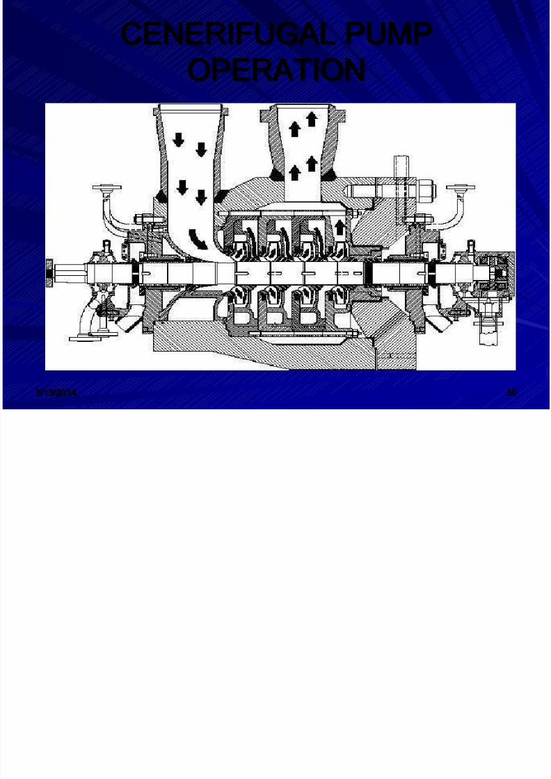
3/13/2014 50
CENERIFUGAL PUMPOPERATION
8/12/2019 Pumps Technology2
http://slidepdf.com/reader/full/pumps-technology2 51/71
3/13/2014 51
LANTERN RING
The leakage rate can be adjusted by tighteningand loosening the packing gland. Lantern Ring It is not always possible to use a standardstuffing box to seal the shaft of a centrifugal
pump. The pump suction may be under avacuum so that outward leakage is impossible orthe fluid may be too hot to provide adequatecooling of the packing. These conditions requirea modification to the standard stuffing box.One method of adequately cooling the packing under these conditions is to include alantern ring.
8/12/2019 Pumps Technology2
http://slidepdf.com/reader/full/pumps-technology2 52/71
3/13/2014 52
LANTERN RING
A lantern ring is a perforated hollow ringlocated near the center of the packing boxthat receives relatively cool, clean liquid fromeither the discharge of the pump or from an
external source and distributes the liquiduniformly around the shaft to provide lubricationand cooling. The fluid entering the lantern ringcan cool the shaft and packing, lubricate thepacking, or seal the joint between the shaft
and packing against leakage of air into thepump in the event the pump suction pressure isless than that of the atmosphere
8/12/2019 Pumps Technology2
http://slidepdf.com/reader/full/pumps-technology2 53/71
3/13/2014 53
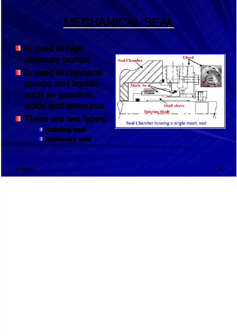
MECHANICAL SEAL
Is used in highpressure pumpsIs used in chemical
pumps and liquidssuch as gasoline,acids and ammonia.There are two types:
Rotating sealStationary seal
8/12/2019 Pumps Technology2
http://slidepdf.com/reader/full/pumps-technology2 54/71
3/13/2014 54
ADVANTAGES OF DISADVFUGALPUMPSANTAGE OF CENTER
They are the least expensive of pump tobuildThey have only one moving part.They do not need a lot of maintenance
The main disadvantage is must be primedbefore they are started

8/12/2019 Pumps Technology2
http://slidepdf.com/reader/full/pumps-technology2 55/71
3/13/2014 55
II. DISPLACEMENT PUMPS
IntroductionDisplacement pumptypes
Reciprocating &Rotary Pumps
Major partsDescribe the operation
Advantages &DisadvantagesDrawing symbol
8/12/2019 Pumps Technology2
http://slidepdf.com/reader/full/pumps-technology2 56/71
3/13/2014 56
INTRODUCTION
Rotary &Reciprocating pumps are positivedisplacement pumps.Positive displacement pump can beclassified by the type of motion of internalelementsThe motion may be either rotary or
reciprocating
8/12/2019 Pumps Technology2
http://slidepdf.com/reader/full/pumps-technology2 57/71
3/13/2014 57
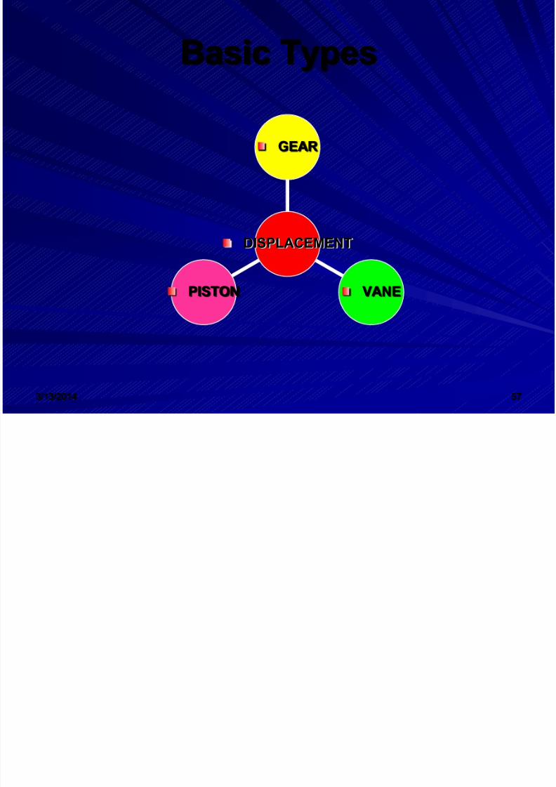
Basic Types
PISTON VANE
GEAR
DISPLACEMENT
8/12/2019 Pumps Technology2
http://slidepdf.com/reader/full/pumps-technology2 58/71
3/13/2014 58
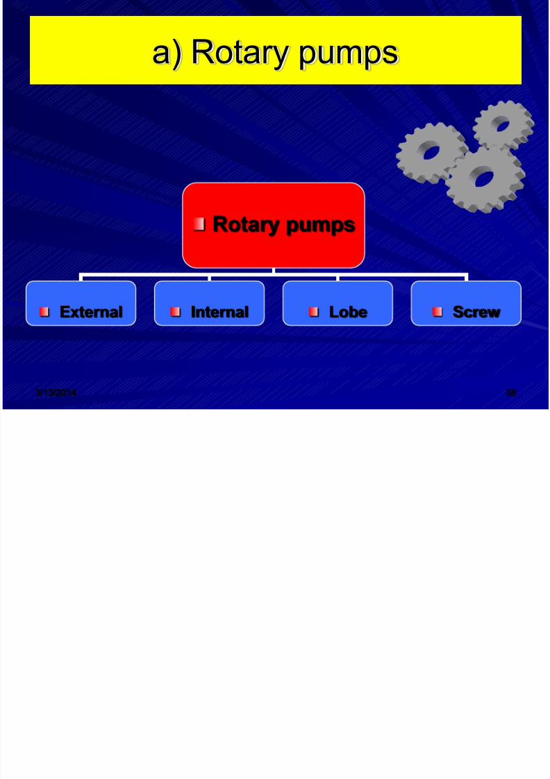
a) Rotary pumps
Rotary pumps
External Internal Lobe Screw

8/12/2019 Pumps Technology2
http://slidepdf.com/reader/full/pumps-technology2 59/71
3/13/2014 59
Major Parts of Rotary Pumps
The major parts of rotarypumps are the: – Suction Inlet – Pumping Element/Drive
shaft* – Housing – Discharge Outlet
– * The pumping elements ineach of the four types aredifferent.
8/12/2019 Pumps Technology2
http://slidepdf.com/reader/full/pumps-technology2 60/71
3/13/2014 60
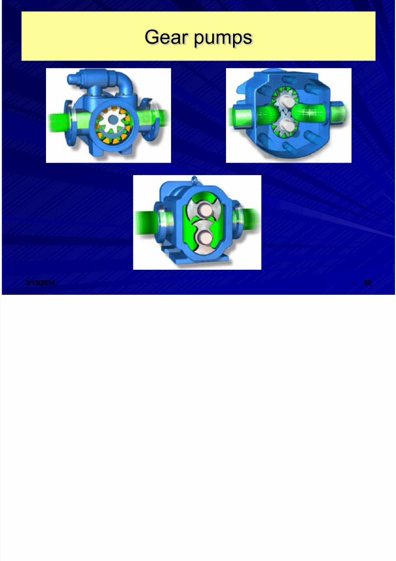
Gear pumps
8/12/2019 Pumps Technology2
http://slidepdf.com/reader/full/pumps-technology2 61/71
3/13/2014 61
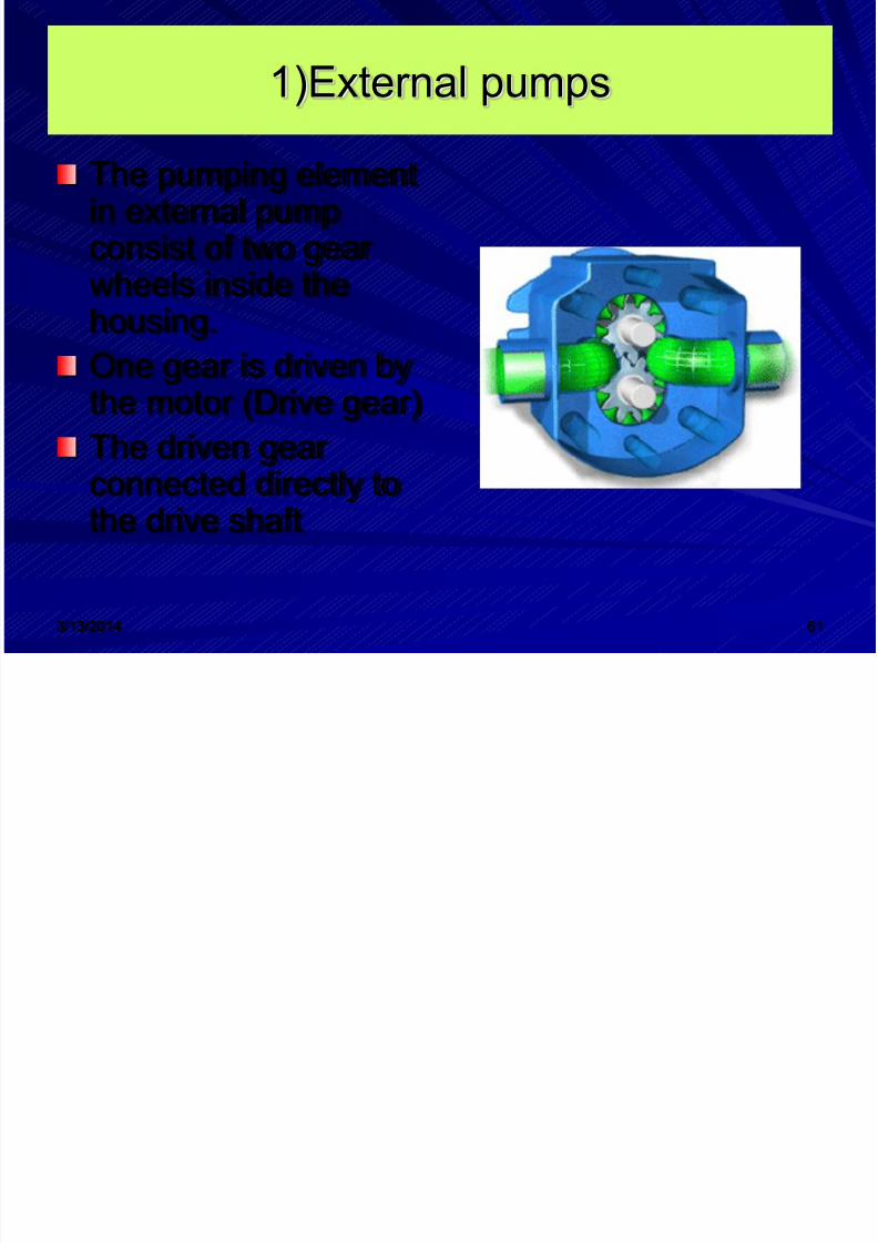
1)External pumps
The pumping elementin external pumpconsist of two gearwheels inside thehousing.One gear is driven bythe motor (Drive gear)The driven gearconnected directly tothe drive shaft

8/12/2019 Pumps Technology2
http://slidepdf.com/reader/full/pumps-technology2 62/71
3/13/2014 62
External Pumps Operation

8/12/2019 Pumps Technology2
http://slidepdf.com/reader/full/pumps-technology2 63/71
3/13/2014 63
External Pumps Operation
From the figure : – Liquid enters the pump through the suction
inlet.
– As the gears rotate, liquid is trapped betweenthe gear teeth and the housing.
– In suction side, volume expand
– In discharge, volume decrease – When the gear teeth mesh, the liquid is
squeezed out through the discharge outlet
8/12/2019 Pumps Technology2
http://slidepdf.com/reader/full/pumps-technology2 64/71
3/13/2014 64
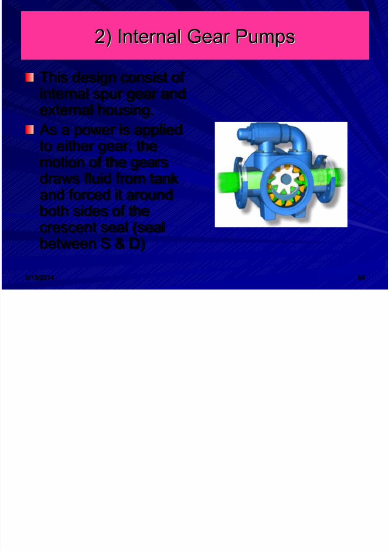
2) Internal Gear Pumps
This design consist ofinternal spur gear andexternal housing.
As a power is appliedto either gear, themotion of the gearsdraws fluid from tankand forced it aroundboth sides of thecrescent seal (sealbetween S & D)
8/12/2019 Pumps Technology2
http://slidepdf.com/reader/full/pumps-technology2 65/71

8/12/2019 Pumps Technology2
http://slidepdf.com/reader/full/pumps-technology2 66/71
Ad t g & Di d t g f R t

8/12/2019 Pumps Technology2
http://slidepdf.com/reader/full/pumps-technology2 67/71
3/13/2014 67
Advantages & Disadvantages of Rotarypumps
High pressure capability (up to 10,000 psi)Small, compact size.High volumetric efficiency.Small change in efficiency through thedesign pressure range
Great flexibility of performance.Only the disadvantage is the gear must fitclose together.

8/12/2019 Pumps Technology2
http://slidepdf.com/reader/full/pumps-technology2 68/71
3/13/2014 68
Reciprocating Pumps
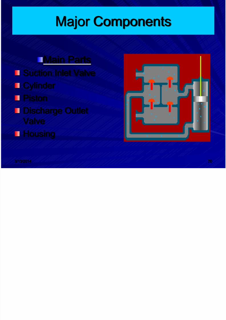
IntroductionMajor Parts
Pump OperationMain typesDrawing Symbol
Advantages &Disadvantages
8/12/2019 Pumps Technology2
http://slidepdf.com/reader/full/pumps-technology2 69/71
3/13/2014 69
Introduction
Reciprocating pumps, like rotary pumps,are positive displacement pumps.Reciprocating means to move with a backand forth motion.The main parts are piston and cylinderThe main types : – Axial design – Radial design
8/12/2019 Pumps Technology2
http://slidepdf.com/reader/full/pumps-technology2 70/71

8/12/2019 Pumps Technology2
http://slidepdf.com/reader/full/pumps-technology2 71/71
Related Documents