Publication 5419-013 REV1.0 Pump 33 DDS 70-3333 Pump 33 DDS Dual Drive System User’s Manual

Welcome message from author
This document is posted to help you gain knowledge. Please leave a comment to let me know what you think about it! Share it to your friends and learn new things together.
Transcript

Publication 5419-013 REV1.0
Pump 33 DDS 70-3333
Pump 33 DDS Dual Drive System
User’s Manual

1Publication 5419-013 REV1.0
Table of Contents
SUBJECT PAGE #Warranty & Repair Information 2Safety Information 3Product Overview - Theory of Operation 4Features 4
Independent, Reciprocating and Twin Condition 4Advanced Connectivity 4Adjustable Motor Force 4Power Connections and Pump Startup 5
Technical Specifications 6Operating Humidity 7Setting Up the Pump 33 DDS (Dual Drive System) 8
Physical Overview 8Syringe Loading 9
Navigating the Pump 33 DDS Graphical User Interface
10
Condition Setup & Operation 10Graphical User Interface Icon Glossary 11Independent Condition Setup 13Independent Condition Run 20Reciprocating Condition Setup 22Reciprocating Condition Run 23Twin Condition Setup 24Twin Condition Run 28
Settings 29Screen Lock & Fast Forward / Fast Reverse 29
Settings Menu 29Pump Information 29Setting Time/Date 30Screen Backlight Adjustment 30Pump Address 31Password 31Baud Rate 32Force Setting 33Alarms 33
SUBJECT PAGE #External Connections 33-37
USB Pinout 33USB Virtual Commport Driver Installation 34Upgrade Software 36RS-232 Pinout 38RS-485 Pinout 38Input / Output Connectors 39
Pump Chain Commands 40Command Conventions and Error Messages 40-41System Commands 41Syringe Commands 46Run Commands 48Rate Commands 48Volume Commands 52Time Commands 53
Digital I/O Commands 54
Internal Commands 54Maintenance, Battery Replacement and Troubleshooting
55
Valve Boxes 56Syringe Manufacturer Volume/Diameter Reference Table
57
Nominal Flow Rates for Syringe Size Reference Table
58
Ordering Information 58Contact Information 59

Publication 5419-013 REV1.02
Warranty and Repair Information
REFER TO SAFETY INFORMATION AND SETTING UP THE HARVARD APPARATUS PUMP 33 DDS BEFORE PLUGGING IN THE PUMP.
CAUTION: For research use only. Not for clinical use on patients.
Manual DescriptionThis manual provides all operational information required to operate the Pump 33 DDS (Dual Drive System).
WarrantyHarvard Apparatus warranties this instrument for a period of two years from date of purchase. At its option, Harvard Apparatus will repair or replace the unit if it is found to be defective as to workmanship or materials. This warranty does not extend to damage resulting from misuse, neglect or abuse, normal wear and tear, or accident. This warranty extends only to the original consumer purchaser.
IN NO EVENT SHALL HARVARD APPARATUS BE LIABLE FOR INCIDENTAL OR CONSEQUENTIAL DAMAGES. Some states do not allow the exclusion or limitation of incidental or consequential damages so the above limitation or exclusion may not apply to you. THERE ARE NO IMPLIED WARRANTIES OF MERCHANTABILITY, FITNESS FOR A PARTICULAR USE, OR OF ANY OTHER NATURE. Some states do not allow this limitation on an implied warranty, so the above limitation may not apply to you.
If a defect arises within the two-year warranty period, promptly contact Harvard Apparatus, 84 October Hill Road, Holliston, Massachusetts 01746 using our toll free number 1–800–272–2775, or outside the U.S. call 508-893-8999. Our E-mail address is [email protected]. Goods will not be accepted for return unless an RMA (returned materials authorization) number has been issued by our customer service department. The customer is responsible for shipping charges. Please allow a reasonable period of time for completion of repairs or replacement. If the unit is replaced, the replacement unit is covered only for the remainder of the original warranty period dating from the purchase of the original device.
This warranty gives you specific rights, and you may have other rights, which vary from state to state.
Repair Facilities and PartsHarvard Apparatus stocks replacement and repair parts. When ordering, please describe parts as completely as possible, preferably using a part number obtained from our Technical Support department. If practical, enclose a sample part or sketch. We offer a complete reconditioning service.
Serial NumbersAll inquiries concerning our products should refer to the serial number of the unit, located on the rear panel.
CalibrationsAll electrical apparatus are calibrated at rated voltage and frequency. While the flow and volume will stay calibrated, the peak pressure may vary. Harvard Apparatus recommends an annual calibration of the pump.

3Publication 5419-013 REV1.0
Safety Information
Please read the following safety precautions to ensure proper use of your syringe pump. If the equipment is used in a manner not specified, the protection provided by the equipment may be impaired.
To Prevent Hazard or Injury: USE PROPER POWER SUPPLYThe pump is supplied with an approved power supply and line cord. To maintain the safety and integrity of the device, use only the following recommended power supplies.
Globtek Inc.Model: GTM96600-6048-18-T3 GTM21097-5048-18
Output: 30V DC 2.0 A 30V DC 1.66 A
Input: 100-240V~, 50/60 Hz, 1.5 A 100-240V~, 50/60 Hz, 1.6 A
CAUTIONRefer to Manual
Protective Ground Terminal
CAUTION: Avoid Pinch Hazard
USE PROPER LINE CORDUse only the specified line cord and power supply for this product and make sure line cord is certified for country of use. The operating voltage range for the Pump 33 DDS is 100-240 VAC, 50-60 Hz. GROUND THE PRODUCTThis product is grounded through the grounding conductor of the power cord. To avoid electric shock, the grounding conductor must be connected to earth ground. Before making any connections to the input or output terminals of the product, ensure that the product is properly grounded. MAKE PROPER CONNECTIONSMake sure all connections are made properly and securely. Any signal wire connections to the unit must be no longer than 3 meters (except RS485 pump-to-pump communication cable).
OBSERVE ALL TERMINAL RATINGSReview the operating manual to learn the ratings on all connections. AVOID EXPOSED CIRCUITRYDo not touch any electronic circuitry inside of the product. AVOID PINCH HAZARDA pinch hazard may exist between the pusher block and end blocks. Avoid placing fingers between these points while the pump is running. DO NOT OPERATE WITH SUSPECTED FAILURESIf damage is suspected on or to the product do not operate the product. Contact qualified service personnel to perform inspection. ORIENT THE EQUIPMENT PROPERLYDo not orient the equipment so that it is difficult to manage the connection and disconnection of devices. PLACE PRODUCT IN PROPER ENVIRONMENTDo not use the equipment in an explosive environment. OBSERVE ALL WARNING LABELS ON PRODUCTRead all labels on product to ensure proper usage.

Publication 5419-013 REV1.04
Product Overview- Theory of Operation
The Harvard Apparatus Pump 33 DDS (Dual Drive System) is a leap forward in syringe pump capability. The Pump 33 DDS has two independent pumping channels controlled by an intuitive touch screen interface. This multi-purpose syringe pump employs advanced syringe mechanisms that include a tight gripping, extremely secure syringe clamp that accommodates syringe sizes 0.5 µl to 60 ml. The Pump 33 DDS offers enhanced flow performance with high accuracy and smooth flow from 1.02 pl/min to 106 ml/min, syringe size dependent. The Pump 33 DDS uses a 7” LCD color touchscreen interface and advanced application software to control operation. The display run screen presents the user with all key dispensing parameters in real time. The application software provides convenient selection of common syringe models from a syringe Lookup Table, as well as insertion of custom syringe specifications. Syringe tables containing all major syringe manufacturers allow simple selection of any compatible syringe size. The system is then able to calculate the cross-sectional area of the syringe selected and calibrate the flow rate and volume accumulation, displaying real-time operating characteristics via on-screen graphics. I/O interfaces permit external control via an independent computer or device.
FeaturesThree operating conditions named Independent, Reciprocating and Twin are available to accommodate a wide range of setups and experimental protocols.
Independent ConditionIndependent Condition allows the Pump 33 DDS to operate as two separate syringe pumps named P1 & P2. P1 is syringe position 1, closest to the touch screen interface and P2 is syringe position 2 and is toward the backside of the unit.
Each syringe will operate independently with different syringe types, size, force, target (volume or time) and flow rate settings. This innovative condition allows you to run two different flows at the same time using one instrument.
Reciprocating ConditionIn Reciprocating Condition, the syringe channels move in opposite directions at the same rate using the same syringe size and type. When combined with a valve box, the reciprocating condition can provide the continuous fluidic delivery of a peristaltic pump with the accurate, pulseless, low flow rates provided by a syringe pump. Twin ConditionThe Twin Condition allows both syringes to operate in the same mode using the exact same syringe type, syringe size, force, target (volume or time) and flow rate settings. The pump also allows the user to combine both flows using the Ganging feature for higher speed and larger volume infusion applications. Advanced ConnectivityThe Pump 33 DDS comes standard with USB and RS-232 connections for PC communication and RS-485 for pump-to-pump communication. An entire suite of ASCII commands is available to control the pump remotely with a PC. The pump contains a footswitch input and digital input/output for each independent pumping channel.
Adjustable Motor ForceThe Pump 33 DDS motors generate up to 70 lbs of linear force in operation. This force is sufficient to damage delicate, low-volume syringes, as well as many standard syringes if pumping viscous fluids. The application software provides controls to allow you to set a maximum force value (calculated as a percentage of the maximum value).Independent Condition Functional Table (Mode Dependent)
Reciprocating Condition Functional Table (Mode Dependent)
Twin Condition Functional Table (Mode Dependent)
Mode Syringe Rate Target Volume/TIme
P1Infuse, Withdraw, Infuse/Withdraw, Withdraw/Infuse
Any size/type 0.5 µl - 60 ml
Any within syringe
capabilityAny (mode dependent)
P2Infuse, Withdraw, Infuse/Withdraw, Withdraw/Infuse
Any size/type 0.5 µl - 60 ml
Any within syringe
capabilitySame as P1
Mode Syringe Rate Target Volume/TIme
P1 Infuse/Withdraw, Withdraw/Infuse
Any size/type 0.5 µl - 60 ml
Any within syringe
capabilityAny
P2 Opposite of P1 Same as P1 Same as P1 Same as P1
Mode Syringe Rate Target Volume/TIme
P1Infuse, Withdraw, Infuse/Withdraw, Withdraw/Infuse
Any size/type 0.5 µl - 60 ml
Any within syringe
capabilityAny (mode dependent)
P2 Same as P1 Same as P1 Same as P1 Same as P1

5Publication 5419-013 REV1.0
Product Overview- Theory of Operation
Power Connections and Pump StartupThe operating voltage for the Pump 33 DDS is 100-240 VAC, 50/60 Hz through an AC/DC converter provided with the pump. Please use the provided or recommended power supply. Using an unapproved power supply will void the warranty.
1. Please ensure that the power switch is in the off position as shown in the Pump 33 DDS Rear View Connections graphic.
2. Plug the power cord in to line voltage. The Pump 33 DDS has a DC power input connector on the rear of the unit. Plug the barrel connector into the DC Input on the rear of the unit.
3. Turn on the main power switch located on the rear panel.
4. The Pump 33 DDS touch screen display will illuminate and display the startup screen while performing self-diagnostics. When complete, the unit will display either the Condition Select, Condition Setup or Condition Run screen depending on the configuration during the last use of the pump.
Pump33 DDS Rear View Connections
CAUTION: Do not connect RS-485 to firewire devices. Damage may occur to pump or device.
Pump Channel 1 & 2 Footswitch
Connections (Footswitch sold separately)
Pump Channel 1 & 2 DIgital I/O
Connections
Main Power Switch
RS-232 Serial Input
Future Expansion
RS-485 Pump-to-Pump Communication
Ports
DC Input (Power Supply
included)
USB Serial Input

Publication 5419-013 REV1.06
Unit Specification Parameter
Accuracy ± 0.25 %
Reproducibility ± 0.05 %
Linear Force (Max, per syringe)
70 lbs (31.75 kg) at 100% Force Setting up to a flow rate of 90 ml/min using a 60 ml syringe with a 32.573 mm inner diameter. 50 lbs (22.6 kg) at 100% Force Setting for flow rates 90 ml/min to 106 ml/min using the same size syringe.
Syringe Size Two Independent syringe mechanisms (noted as syringe drive P1 & P2)
Minimum 0.5 µl (0.103 mm minimum inner diameter)
Maximum 60 ml (32.573 mm maximum inner diameter)*
Flow Rate:
Minimum 1.02 pl/min (0.5 µl syringe, 0.103 mm inner diameter)
Maximum 106 ml/min (60 ml syringe, 32.573 mm diameter )
Display 7" WQVGA TFT Color Display with Touch Screen
Modes of Operation:
Twin Condition
Both syringes of the same size operate identically (flow rate, direction & volume)
Independent Condition
Both syringes operate independently
Reciprocating Condition
Continuous flow, both syringes of the same size operate identically in opposite directions
Non-Volatile Memory Stores all settings
Pump Command Control
ASCII Command Set
Real time Clock Yes, with battery backup (battery included and required for real time clock)
Connectors:
Power Barrel connector, (-) barrel (+) post 2mm X 5mm male plug
RS-485 IEEE-1394, 6 position
USB Type B
RS-232 9 pin D-Sub Connector
(I/O) TTL 15-pin D-sub connector (one for each axis)
Footswitch Connections
Mini phono jack
Drive Motor Two independent stepper motors
Motor Drive Control MCU controlled
Unit Specification Parameter
Step Rate:
Minimum 27 sec/µstep
Maximum 26 µsec/µstep
Stall Detection Yes, independent axis stall detection
Input Power 30 V, 1.66 A
Power Supply Input 100-240 VAC, 50/60 Hz, Output 30V 2.0 A, 50 Watts
Dimensions (L x D x H) 11” x 15” x 8” (28 cm x 39 cm x 21 cm )
Weight 21 lbs (9.09 kg)
Operating Temperature
4°C to 40°C (40°F to 104°F)
Storage Temperature -10°C to 70°C (14°F to 158°F)
Operating Humidity 80% @ 25° C ambient temperature
Storage Humidity 20% to 80% RH, non-condensing
Classification Class I
Pollution Degree 1
Installation Category II
Regulatory Certifications
CE, ETL (UL & CSA), CB Scheme, EU RoHS, WEEE
*NOTE: Some larger syringes may be compatible with the Pump 33 DDS. Please contact Technical Support for more information.
Technical Specifications

7Publication 5419-013 REV1.0
Operating Humidity
The following is a chart of operating humidity versus temperature for the Pump 33 DDS. Please note as operating temperature increases, the maximum allowable operating humidity decreases.
Operating Humidity vs. Temperature Chart

Publication 5419-013 REV1.08
Setting up the Pump 33 DDS
Physical Overview The following diagrams show the important components of the Pump 33 DDS.
Syringe Loading The Pump 33 DDS syringe mechanisms accommodate syringe sizes 0.5 ul to 60 ml. The pump includes brackets and clamps to hold different sizes and types of syringes for various applications. The following uses P1 as the mechanism example. Both syringe pump mechanisms operate in the same manner.
The call out numbers in the graphic below correspond to the bold numbers in the text that follows.
Pump33 DDS Top View
Pump Channel 2 (P2)
Pump Channel 1 (P1)
End Block (P2)
End Block (P1)
Lead Screw (P1)
Touch Screen
Knob for Pusher Block (P1) Lead Screw Release
Knob for Pusher Block (P2) Lead Screw Release
Pusher Block (P2) Lead Screw (P2)Guide Rods (P2)
Syringe Clamp/Syringe Holder Block (P2)
Syringe Clamp/Syringe Holder Block (P1)
Pusher Block (P1)
Guide Rods (P1)
(1) Syringe Plunger RetainingBracket & Retaining Bracket Tightening Thumbscrews
(14) Clamp Collars
(4) High Force Syringe Clamp Tightening Thumbscrews
(5) Syringe Holder Block
(6) High Force Syringe Clamp
(7) Low Force Syringe Clamp Tightening Thumbscrew
(9) Syringe Barrel Retaining Bracket & Retaining Bracket Tightening Thumbscrews
(8) Low Force Syringe Clamp(2) Pusher Block
(3) Pusher Block Leadscrew Release Knob
(12) Syringe Barrel Flange
(11) Syringe Plunger
(10) Syringe Plunger Flange
(13) Syringe Barrel

9Publication 5419-013 REV1.0
Setting up the Pump 33 DDS
The Syringe Holder Block (5) and Pusher Block (2) are fitted with movable Retaining Brackets (1, 9) which firmly hold the syringe barrel Flange (12) and Syringe Plunger Flange (10) during infuse or withdraw modes. The Syringe Holder Block (5) has two types of syringe clamps used to secure the syringe barrel to the Syringe Holder Block. They are the Low Force Syringe Clamp (8) and High Force Syringe Clamp (6). When loading the syringe into the pump it is necessary to adjust retaining brackets and to select and adjust the proper Syringe Clamp (6, 8) for your application.
1. Remove the High Force Syringe Clamp (6) by unscrewing the two High Force Syringe Clamp Tightening Thumbscrews.
2. Loosen the two thumbscrews (9) on the Syringe Holder Block and the two thumbscrews (1) on the Pusher Block to free the Syringe Plunger and Syringe Barrel Retaining Brackets.
3. To free the Pusher Block (2) from the Leadscrew, turn the Pusher Block Leadscrew Release Knob (3) on the front of the block until the knob slips into the slots. This will disengage the Pusher Block and allows manual Pusher Block adjustment to accommodate the Syringe Plunger (10). In addition to manual pusher block adjustment, the user can also move the Pusher Block using Fast Forward and Fast Reverse buttons. This feature will be discussed in the Condition Setup section of this manual.
4. Place the Syringe Barrel (13) on the Syringe Holder Block (5) and move the Pusher Block (2) to accommodate the plunger.
5. Make sure the Syringe Barrel Flange (12) and the Syringe Plunger Flange (10) are held by the Retaining Brackets (1, 9).
6. Press the Retaining Brackets firmly against the flanges and tighten with the Tightening Thumbscrews (1, 9).
7. Place the Syringe Clamp (6 or 8 depending on your application) over the syringe barrel and secure. Secure the High Force Syringe Clamp (6) by tightening the two High Force Syringe Clamp Tightening Thumbscrews (4). The High Force Syringe Clamp can invert to accommodate smaller size syringes. For Low Force applications, place the Low Force Syringe Clamp on the Syringe barrel. Secure the Low Force Syringe Clamp by tightening the Low Force Syringe Clamp Tightening Thumbscrews (7). The diagrams show the Low Force and High Force Syringe configurations.
8. Clamp collars (14) are included to protect fragile syringes. The collars are placed and tightened along the guide rides to allow a mechanical stop. When the pusher block reaches the tightened clamp collar, it will stall, stopping the active pump.
Low Force Syringe Clamp Examples
Pump 33 DDS Showing Syringes Installed with Low Force (P1) and High Force (P2) Syringe Clamps
High Force Syringe Clamp Examples
Note: The picture on the right shows a small size high force syringe secured with the inverted High Force Syringe Clamp
Pump Channel 1 (P1)
Pump Channel 2 (P2)
Low Force Syringe Clamp
Example
High Force Syringe Clamp
Example

Publication 5419-013 REV1.010
Navigating the Pump 33 DDS Graphical User Interface
The Pump 33 DDS employs a button enabled Graphical User interface controlled with a large 7” LCD Color Touchscreen display for quick and easy setup.
There is a setup and run screen for all three operation conditions Independent, Reciprocating and Twin. The setup and run screens for all three conditions are similar with common buttons. There are small functional differences for each condition based on the features that condition supports.
When you first turn on the unit after delivery from the Harvard Apparatus factory, the following start up screen will briefly appear.
Then the unit will display the Condition Select Screen. If the Condition Select screen does not appear, please press the back button (see Independent Condition below) until you enter the Condition Select Screen.
Select the desired operational condition and you will enter the setup screen for that condition. The following explains the graphical user interface for all three operating conditions (Independent, Reciprocating and Twin).
Start Up Screen
Condition Select Screen

11Publication 5419-013 REV1.0
Graphical User Interface Button Glossary
The following buttons are part of the Pump 33 DDS (Dual Drive System) graphical user interface.
Mode Select – Sets Pump Channel Mode
Syringe Select – Sets Syringe Type & Size
Target Select – Sets Target Volume or Time
Rate Select – Sets Flow Rate
Run/Stop Pump Channel 1 (P1) – Starts / Stops Pump Channel 1 (P1) Only in Independent Condition.
Run/Stop Pump Channel 2 (P2) – Starts / Stops Pump Channel 2 (P2) Only in Independent Condition.
Run/Stop Pump Channel 1 & 2 (P1 & P2) – Starts / Stops both Pump Channel 1 (P1) and Pump Channel 2 (P2).
Return to Previous Screen – Returns the user to the previous screen.
System Settings – Enters System Settings Menu to adjust Time/Date, Backlight, Pump Address, Baud Rate, Password, Force, Alarm, Pump Information and Upgrade Software features.
Fast Forward / Fast Reverse – Automatically advances or reverses the Pump Channel 1 (P1) and / or Pump Channel 2 (P2) pusher blocks. Select P1 and/or P2 to enable the feature for that pump channel.

Publication 5419-013 REV1.012
Graphical User Interface Button Glossary
Minimum Value Allowed – Used to select the minimum value allowed for the parameter entry.
Maximum Value Allowed – Used to select the maximum value allowed for the parameter entry.
Run Preview Screen – Brings the user to the Run Screen.
Accept – Used to accept the parameters/settings on a screen and advance to the next menu.
Cancel – Used to cancel any changes/entries on a screen in the menu.
Reset Counters Pump Channel 1 (P1) – Clears the counter/timers for Pump Channel 1 (P1) for Independent Condition Only.
Reset Counters Pump Channel 2 (P2) – Clears the counter/timers for Pump Channel 2 (P2) for Independent Condition Only.
Reset Counters – Clears the counter/timers for Reciprocating and Twin Condition.

13Publication 5419-013 REV1.0
Independent Condition Setup
Independent Condition allows the Pump 33 DDS to operate as two separate syringe pumps named P1 & P2. P1 is syringe position 1 (Channel 1), closest to the touch screen interface and P2 is syringe position 2 (Channel 2) and is toward the backside of the unit.
Each syringe will operate independently with different syringe types, size, force, target (volume or time) and flow rate settings. This innovative condition allows you to run two different flows at the same time using one instrument.
Select “Independent” from the Condition Select Screen.
The Independent Condition Setup Screen will appear. There are two sections to each Condition Setup screen. The top two thirds of the screen is dedicated to the mode, syringe type/size, flow rate and target volume or time setup for Pump Channel 1 (P1) and Pump Channel 2 (P2).
Condition Select Screen (Independent Condition Selected)

Publication 5419-013 REV1.014
Independent Condition Setup
Independent Condition Setup Screen BUTTON Guide
Independent Condition Setup Screen
The bottom of the screen contains the Run, Fast Forward / Fast Reverse and System settings buttons. This manual addresses the Run functions after each condition setup section. The Settings section of this manual covers the system setting functions.
The following is a summary of the Independent Condition Setup Screen with detailed explanation of each button function.

15Publication 5419-013 REV1.0
1) MODE SELECT - Select the Mode for Pump Channel 1 & Pump Channel 2. Press the Mode Select button for either Pump Channel 1 (P1) or Pump Channel 2 (P2). The following screen will appear. The Mode for Pump Channel 1 (P1) and Pump Channel 2 (P2) can be set individually.
The four Modes are:
a. Infuse Only - The syringe will operate in infuse mode only. Facing the Pump 33 DDS, the pusher block will push the syringe plunger from left to right at the set flow rate and volume/time.
b. Withdraw Only - The syringe will operate in withdraw mode only. Facing the Pump 33 DDS, the pusher block will pull the syringe plunger from right to left at the set flow rate and volume/time.
c. Infuse/Withdraw - The syringe will operate in Infuse/Withdraw mode. Facing the Pump 33 DDS, the pusher block will push the syringe plunger from left to right at the set flow rate and volume while infusing and will then pull the syringe plunger from right to left at the set flow rate while withdrawing. The infuse and withdraw flow rates can be different. For example: An experiment may require a low flow rate for infusion but require a fast withdraw rate for quick syringe refill.
d. Withdraw/Infuse - The syringe will operate in Withdraw/Infuse mode. Facing the Pump 33 DDS, the pusher block will pull the syringe plunger from right to left at the set flow rate and volume while withdrawing and will then push the syringe plunger from left to right at the set flow rate while infusing. The withdraw and infuse flow rates can be different.
Select the desired modes for both P1 and P2. The modes can be set differently while in Independent Condition. Once selected, the mode button will turn green. Press the Green check button in the bottom right hand corner of the screen to accept the Mode selections for P1 and P2. Press the Red X to discard the selections and return to the Independent Condition Setup screen.
Independent Condition Setup
Independent Condition Mode Select Screen
Select Syringe Screen Showing Force Alarm
2) SYRINGE SELECT - Select the syringe size and type for Pump Channel 1 (P1) & Pump Channel 2 (P2).
Press the Syringe Select button for either Pump Channel 1 (P1) or Pump Channel 2 (P2). Note: Unlike the Mode Select section, the Independent Condition syringe selection requires the user to select and set the P1 syringe first and then select and set the P2 syringe.
The following screen will appear.
The Pump 33 DDS has many syringe manufacturers listed in the Select Syringe table. The left hand side of the Select Syringe screen lists the syringe manufacturer and type. The right hand side of the Select Syringe screen sets the syringe size. In the example above a 50 ml, Hamilton 1000 Series syringe is selected. Once the proper syringe manufacturer, type and size has been selected, press the Green check mark button to accept or press the Red X button to return to the Independent Condition Setup screen.
Depending on the syringe type and size, the Pump 33 DDS may display a force warning. A high set force could damage a small glass syringe. In this case, the pump will alert the user to lower the Pump 33 DDS linear force. Please see the settings section for information about adjusting linear force.
Select Syringe Screen

Publication 5419-013 REV1.016
Independent Condition Setup
The Pump 33 DDS also supports syringes not specifically listed in the syringe table through the Custom Syringe Selection. Select Custom Syringe from the syringe selection table.
The Custom Syringe Settings Screen will appear. Enter the inner diameter and capacity of the syringe and press the green check mark button to accept and return to the Independent Condition setup screen. The syringe capacity will appear in either µl or ml. Pressing the units text will toggle the inputs between µl and ml.
Perform the same actions on the P2 Syringe Select to set the syringe for Pump Channel 2 (P2). Note: the Custom Syringe diameter range is 0.1 mm to 45 mm and the Custom syringe capacity is 0.5 to 1000 ml. This range falls outside of the syringe size range specified in this manual because some larger syringes may be compatible with the Pump 33 DDS. Please contact Technical Support for more information.
Select Syringe - Custom Syringe Screen
Custom Syringe Settings Screen
Set Rate Screen (Infuse Mode Shown)
3) RATE SELECT – Select the flow rate for Pump Channel 1 & Pump Channel 2. Independent Condition requires the user to enter a flow rate for the selected mode on both P1 & P2. The user will need to enter either one or two rates depending on the mode selected. Infuse and Withdraw modes require one rate while Infuse/Withdraw and Withdraw/Infuse require two rates.
Press the Rate Select button for Pump Channel 1 (P1) or Pump Channel 2 (P2). The Set Rate screen will appear. Infuse mode is shown in the screen shot below. There are four selectable entries on the Set Rate screen.
Flow Rate - Enter the flow rate in the number entry box using the keypad located on the right hand side on the screen. When selecting Withdraw mode, use the same procedure to enter the Withdraw rate.

17Publication 5419-013 REV1.0
Units - Set the units for the desired flow rate by touching the units found on the right of the number entry box. The following Select Units popup box will appear. Select the volume units from the left hand side of the Select Units popup and time units from the right hand side. Press the green check mark button to accept and return to the Set Rate screen. Note: All other selectable entries on the Set Rate screen will be grey until the current entry is complete.
Set Flow Rate Units (Select Units)
Set Rate Screen with MIN Flow Rate Selection
Infuse or Withdraw Mode Target Volume Setting
Set Rate Screen with MAX Flow Rate Selection
Press the green check mark button to accept and return to the Independent Condition Setup Screen.
4) TARGET SELECT – Select the target volume or time for Pump Channel 1 & Pump Channel 2. The TARGET SELECT parameter entries are different for Infuse and Withdraw only versus Infuse/Withdraw and Withdraw/Infuse.
Set Target Volume - Set the Target Volume for Pump Channel 1 & Pump Channel 2. Independent Condition requires the user to enter a Target Volume or Time for the selected mode on both P1 & P2.
On the Independent Condition setup screen, press the Target Select button for Pump Channel 1 (P1) or Pump Channel 2 (P2). The Set Target Volume or Time screen will appear. Infuse and Withdraw modes allow the user to select either a target volume or time, while Infuse/Withdraw and Withdraw/Infuse allow a target volume or continuous operation. Select the Target Volume entry box. The box will become white to show it is active. Either select the required volume or select the MAX button to set the maximum volume of the set syringe.
Set Maximum and Minimum Flow Rate Buttons – There are two buttons in the bottom left quadrant of the Set Rate screen. Selecting either the MAX or MIN button will automatically set the maximum or minimum flow rate for the set syringe.
Note: Selecting either MAX or MIN will overwrite any previous flow rate entry.
Independent Condition Setup

Publication 5419-013 REV1.018
Infuse or Withdraw Mode Target Time Setting
Infuse/Withdraw or Withdraw/Infuse Set Target Volume Screen
Setup Screen Showing Target Select “Continuous Operation”
Independent Condition Setup
Select the Target Time entry box to enter the target time. The time can be entered in HH:MM:SS or sec. The user can toggle between HH:MM:SS or sec by pressing the time units to the right of the target time entry box.
5) Fast Forward / Fast Reverse Buttons
The Fast Forward button advances the pusher block from left to right (infuse direction) for P1 and/or P2. These buttons are available at the bottom of all main Condition setup and Run screens. The Fast Reverse button advances the pusher block from right to left (withdraw direction) for P1 and/or P2. This is useful to set the pusher block in the correct location for the given application. Note: The user can move the pusher blocks manually. Please see the Syringe Loading section for information on moving the P1 and P2 pusher blocks manually.
To use the Fast Forward and Fast Reverse buttons, select either the P1 and/or P2 buttons located at the bottom center of all main condition setup and run screens. Once selected, the button will turn bright green. Then use the Fast Forward/Fast Reverse buttons to the right of the P1 and P2 buttons to move the P1 and or P2 pusher blocks. The Fast Forward/Fast Reverse buttons must remain pressed to move the pusher block. Once released the pusher block will stop immediately. During operation, the Pump 33 DDS will display a red message box showing the pusher block direction. The following examples are from the setup screen. This same functionality is available in the condition run screens. Note: Certain buttons are disabled in certain conditions. Stall detection is disabled during Fast Forward/Fast Reverse operation.
The Infuse/Withdraw and Withdraw/Infuse modes allow only a target volume. The Target Time selection will not be available. Select the required volume by entering the Target Volume and pressing the green check mark button. The pump will alternate infusions and withdrawals up to the syringe capacity until the target volume has been infused. The last phase of an Infuse/Withdraw or Withdraw/Infuse will return the pusher block to its original location.
For example, setting an Infuse/Withdraw target volume or selecting the Continuous Operation button of 50 ml with a 50 ml syringe will infuse 50 ml, then withdraw 50 ml. Setting a Withdraw/Infuse target volume of 75 ml with the same syringe will withdraw 50 ml, infuse 50 ml, withdraw 25 ml, and infuse 25 ml.
Continuous Operation: Selecting “0” as a target volume or selecting the Continuous Operation button in the Infuse/Withdraw and Withdraw/Infuse modes allows continuous operation until the user stops the pump channel. For example: Selecting “0” as a Target Volume or selecting the Continuous Operation button for a 50 ml syringe using Infuse/Withdraw mode, would set the syringe to infuse 50 ml then withdraw 50 ml. This will repeat indefinitely until the user stops the pump channel.

19Publication 5419-013 REV1.0
Independent Condition Setup
Pump Channel 1 (P1) & 2 (P2) Fast Forward Feature
Pump Channel 2 (P2) Fast Reverse Feature
Pump Channel 1 (P1) Fast Reverse Feature
Pump Channel 1 (P1) & 2 (P2) Fast Reverse Feature
Pump Channel 1 (P1) Fast Forward Feature Pump Channel 2 (P2) Fast Forward Feature

Publication 5419-013 REV1.020
Independent Condition Run
P33 DDS Independent Condition Setup Screen BUTTON Guide
Independent Condition Run Screen BUTTON Guide
The following is the Independent Run screen button guide with call out definitions.
The following section covers the Independent Run screen. Once the Independent Condition parameters are set, the user can start P1 and P2 individually or at the same time. This operation can be performed from the setup or run screens.
Refer to the setup screen button guide shown below (defined at the start of this section). To start the Pump 33 DDS from the setup screen press the Pump Channel 1 (P1) Run/Stop button (5) to start P1 only. Select the Run/Stop button (10) for Pump Channel 2 (P2) to start P2 only. Select the Run/Stop button (11) to start both channels at the same time.
Selecting the magnifying glass button (12) will send the user to the Run screen without starting P1 and/or P2.

21Publication 5419-013 REV1.0
13) CURRENT OPERATING CONDITION – The top left hand corner of any Pump 33 DDS screen lists the title of that screen.
14) P1 GRAPHICAL SYRINGE STATUS – This graphic provides the current volume in text and in graphical form.
15) RUN/STOP PUMP CHANNEL 1 (P1) – Press to start/stop P1.
16) RESET COUNTERS PUMP CHANNEL 1 (P1) – Press to reset the various counters (see 25).
17) RETURN TO SETUP SCREEN – Returns the user to the setup screen.
18) SYSTEM SETTINGS – Opens the system settings menu. Please see the System Settings section for details.
19) SCREEN LOCK/UNLOCK – Locks the screen from setting changes. The user can also access the screen Lock/Unlock through the Condition setup screen.
20) FAST/FORWARD FAST REVERSE P1 & P2 – Advances the P1 and/or P2 pusher block. Please see the Independent Condition setup section of this manual for details.
21) RUN/STOP PUMP CHANNELS 1 (P1) and 2 (P2) – Press to start/stop both P1 and P2 at the same time.
22) RESET COUNTERS PUMP CHANNEL 2 (P2) – Press to reset the various counters for P2 (see 25).
23) RUN/STOP PUMP CHANNEL 2 (P2) – Press to start/stop P2.
24) P2 GRAPHICAL SYRINGE STATUS – This graphic provides the current volume in text and in graphical form.
25) REALTIME STATUS – Displays the set Mode, Syringe, Time Elapsed and Time Left for the current run Target and Infused volume along with the set flow rates and force settings for both P1 and P2. The Time Elapsed, Time Left and Infused Volume display automatically update during the experiment.
Independent Condition Run
Independent Condition Run Screen Showing Locked Screen
Independent Condition Setup Screen Showing Locked Screen
NOTE: Please review the System Settings section to learn how to set the unlock password before engaging a screen lock. Press the UNLOCK button twice to lock the screen. Once locked the button graphic will turn red. Press again to unlock using the set password. When the Pump 33 DDS screen is locked, all setting buttons will be grey and not accessible until the screen is unlocked.

Publication 5419-013 REV1.022
In Reciprocating Condition, the two syringe channels move in opposite directions at the same rate using the same syringe size and type. For example, when P1 is infusing, P2 is withdrawing at the same rate. When combined with a valve box, the reciprocating condition can provide the continuous fluidic delivery of a peristaltic pump with the accurate, smooth, low flow rates provided by a syringe pump.
Select “Reciprocating” from the Condition Select Screen.
The Reciprocating Condition Setup follows the same procedure as Independent condition with one exception. The user only needs to set the Mode Select, Syringe Select, Rate Select and Target Select for the P1 Pump Channel and the P2 Pump Channel will be automatically set.
Reciprocating Condition Setup
P33 DDS Condition Select Screen (Reciprocating Condition Selected)
Reciprocating Condition Setup Screen
1) MODE SELECT - Select the Mode for Pump Channel 1 & Pump Channel 2. Reciprocating Condition will automatically set the opposite mode for P2 once the user sets the P1 mode. The two Modes are:
a. Infuse/Withdraw - The syringe will operate in Infuse/Withdraw mode only. P1 will infuse first while P2 is withdrawing. Facing the Pump 33 DDS, the pusher block for the infusing pump channel will push the syringe plunger from left to right at the set flow rate and volume/time while infusing and the pusher block for the withdrawing channel will pull the syringe plunger from right to left at the set flow rate while withdrawing. The infuse and withdraw flow rates can be different. For example: An experiment may require a low flow rate for infusion but require a fast withdraw rate for quick syringe refill.
b. Withdraw/Infuse - The syringe will operate in Withdraw/Infuse mode only. P1 will withdraw first while P2 is infusing. Facing the Pump 33 DDS, the withdrawing channel will pull the syringe plunger from right to left at the set flow rate while withdrawing. The pusher block for the infusing pump channel will push the syringe plunger from left to right at the set flow rate and volume while infusing. The infuse and withdraw flow rates can be different. For example: An experiment may require a low flow rate for withdrawal but require a fast infuse rate for quick delivery.
P33 DDS Reciprocating Condition Mode Select Screen (Showing P1 Selection and P2 Setting)

23Publication 5419-013 REV1.0
2) SYRINGE SELECT - Select the syringe size and type for Pump Channel 1 (P1) & Pump Channel 2 (P2). The Syringe Select Methods for Reciprocating Condition is similar to Independent Condition. Since both P1 and P2 are the same size in Reciprocating Condition, the user only needs to set the syringe for P1 and the syringe for P2 will set automatically.
3) RATE SELECT – Select the Infuse/Withdraw or Withdraw/Infuse flow rates. The Rate Selection will vary depending on the mode selected. The Infuse/Withdraw or Withdraw/Infuse rate entry is the same as covered in the Independent Condition Rate Select section.
a. Infuse/Withdraw Mode Rate Select – Select the Infuse rate and Withdraw rate. The user can set different rates for Infuse and Withdraw.
b. Withdraw/Infuse Mode Rate Select - Select the Withdraw rate and Infuse rate. The user can set different rates for Infuse and Withdraw.
4) TARGET SELECT – Select the Target Volume depending on the Mode selected. Infuse/Withdraw or Withdraw/Infuse Target Select entry is the same as covered in the Independent Condition Target Select section.
The Reciprocating Condition Run screen is similar to the Independent Condition Run screen. Please see below for a summary of the Reciprocating Condition Run screen.
Reciprocating Condition Setup
Reciprocating Condition Run
Reciprocating Condition Run Screen BUTTON Guide

Publication 5419-013 REV1.024
Twin Condition Setup
1) MODE SELECT - Select the Mode for Pump Channel 1 & Pump Channel 2. Twin Condition will automatically set the same mode for P2 once the user sets the P1 mode.
The Twin Condition allows both syringes to operate in the same mode using the exact same syringe type, syringe size, force, target (volume or time) and flow rate settings. The pump also allows the user to combine both flows through the Ganging feature for higher speed and larger volume infusion applications.
The Twin Condition Setup follows the same procedure as Independent condition with two exceptions. First, the user only needs to set the Mode Select, Syringe Select, Rate Select and Target Select for the P1 Pump Channel and the P2 Pump Channel will be automatically set. The second difference is the syringe ganging feature, which will be discussed under SYRINGE SELECT, below.
Twin Condition Setup Screen
Twin Condition Syringe Select Screen (Showing Gang x1 x2 Toggle Selection)
The four Modes are:
a. Infuse Only - The P1 and P2 syringes will both operate in infuse mode. The volume or time of the cycle is set in the Target Select selection. Facing the Pump 33 DDS, the P1 and P2 pusher blocks will push the syringe plungers from left to right at the set flow rate and volume/time.
b. Withdraw Only - The P1 and P2 syringes will both operate in withdraw mode. The volume or time of the cycle is set in the Target Select selection. Facing the Pump 33 DDS, the P1 and P2 pusher blocks will pull the syringe plungers from right to left at the set flow rate and volume/time.
c. Infuse/Withdraw - The P1 and P2 syringes will both operate in infuse/withdraw mode. The volume of the cycle is set in the Target Select selection. Facing the Pump 33 DDS, the P1 and P2 pusher blocks will push the syringe plungers from left to right and then pull the syringe plungers from right to left at the set flow rate to process the programmed volume. Setting a volume of zero will allow both syringes to infuse/withdraw continuously at the maximum syringe volume.
d. Withdraw/Infuse - The P1 and P2 syringes will both operate in Withdraw/Infuse mode. The volume of the cycle is set in the Target Select selection. Facing the Pump 33 DDS, the P1 and P2 pusher blocks will pull the syringe plungers from right to left and then push the syringe plungers from left to right at the set flow rate to process the programmed volume Setting a volume of zero will allow both syringes to withdraw/infuse continuously at the maximum syringe volume.
2) SYRINGE SELECT - Select the syringe size and type for Pump Channel 1 (P1) & Pump Channel 2 (P2). The Syringe Select Methods for Twin Condition is the similar to Independent Condition. Since both P1 and P2 are the same size in Twin Condition, the user only needs to set the syringe for P1 and the syringe for P2 will set automatically.
The Twin Condition supports use of the Ganging feature, which allows the user to combine the flow rates and volumes for the two identical syringes in Twin mode. To set the Gang feature select the Gang button located in the top right hand corner of the syringe type selection menu. Pressing the Gang button toggles between x1 and x2.

25Publication 5419-013 REV1.0
Twin Condition Setup
Twin Condition Syringe Select Screen (Showing Gang x1 and 2.5 ml Syringe Selection)
3) RATE SELECT – Select the Infuse, Withdraw, Infuse/Withdraw or Withdraw/Infuse flow rates. The Rate Selection will vary depending on the mode selected. The Infuse, Withdraw, Infuse/Withdraw or Withdraw/Infuse rate entry is the same as covered in the Independent Condition Rate Select section.
a. Infuse Mode Rate Select – Select the infuse rate for P1. The same rate will be automatically set for Pump Channel 2 (P2) infuse rate.
b. Withdraw Mode Rate Select – Select the withdraw rate for P1. The same rate will automatically set for the P2 withdraw rate.
c. Infuse/Withdraw Mode Rate Select – Select the Infuse rate and Withdraw rate for P1. The user can set different rates for Infuse and Withdraw. The same rates will automatically be set for P2.
d. Withdraw/Infuse Mode Rate Select – Select the Withdraw rate and Infuse rate. The user can set different rates for Infuse and Withdraw. The same rates will automatically be set for P2.
NOTE: Please see 4 below for details on the impact of the Ganging feature on the Rate Select setting.
4) TARGET SELECT – Select the Target Volume or Time depending on the Mode selected. The Infuse, Withdraw, Infuse/Withdraw or Withdraw/Infuse Target Select entry is the same as covered in the Independent Condition Target Select section.
NOTE: Please see below for details on the impact of the Ganging feature on the Rate and Target Select settings.
a. Ganging Feature RATE AND TARGET SELECT – The Ganging feature described above impacts the Rate Select setting. When the user selects the x2 Gang feature in the Twin Condition Select Syringe table, the flow rate and target ranges listed are double the allowed flow rate and target ranges of a single syringe.
This requires the user to connect the output of both syringes together using the same tubing size and length to produce the correct flow rates. The following are examples using the x1 and x2 Gang feature.
Example x1 Ganging: The user requires the proper setting for the following application, Mode Select setting of Infuse, using a 2.5 ml syringe (inner diameter 7.285 mm). The user wants both syringes to infuse at the same rate and volume. The syringe outputs will not be connected together. In this case, the user will select the Gang x1 toggle selection located in the top right hand corner of the Select Syringe menu along with the proper 2.5 ml syringe.
The x1 selection allows both syringes to operate as two identical individual syringes with the same mode, syringe, flow rate and target volume or time. The x2 selection doubles the flow and volume. Note: This requires the user to connect the output of both syringes together using the same tubing size and length.

Publication 5419-013 REV1.026
The Rate Select screen for the x1 Gang selection will look the same as the Rate Select screen for both Independent and Reciprocating Condition. The user can set the flow rate for both Twin syringes. In the case of a 2.5 ml syringe, the available flow rate range is 5.106 nl/min to 5.302 ml/min. In Twin Condition, the user will select one rate for both P1 and P2 as shown in the screen below.
The Target Select screen for the x1 Gang selection will look the same as the Target Select screen for both Independent and Reciprocating Condition. In Twin Condition, the user will select one target volume or time for both P1 and P2 as shown in the screen below. The user can set the target flow rate or time (time available in Infuse and Withdraw modes only) rate for both Twin syringes. In the case of a 2.5 ml syringe, the available maximum volume is 2.5 ml as shown in the screen below.
When the user runs the setup for this example the Twin Run screen will display the pump status along with the set flow rate and target volume.
Twin Condition Setup
Twin Condition Rate Select for x1 Gang Setting
Twin Condition Run Screen for x1 Gang Setting
Twin Condition Target Select for x1 Gang Setting Showing 2.5 ml maximum volume

27Publication 5419-013 REV1.0
Example x2 Ganging: The user wants both 2.5ml syringes to infuse at the same rate and volume. The syringe outputs will need to be connected together by the user. In this case, the user will select the Gang x2 toggle selection located in the top right hand corner of the Select Syringe menu along with the proper 2.5 ml syringe. The Rate Select screen for the x2 Gang selection will look similar to the Rate Select screen for both Independent and Reciprocating Condition with two small differences. The first difference is that the label “Gang 2” will appear in the description of the Rate Select screen. The user can set the flow rate for both Twin syringes. In the case of a single 2.5 ml syringe (x1 Ganging), the available flow rate range is 5.106 nl/min to 5.302 ml/min. However, in this example, the outputs of both P1 and P2 syringes will be tied together. This will double the available flow rate. For this example, the available flow rate range is 10.21 nl/min to 10.6 ml/min, which is double 5.106 nl/min to 5.302 ml/min. In Twin Condition, the user will select one rate for both P1 and P2 as shown in the following screen.
Twin Condition Setup
Twin Condition Rate Select for x2 Gang Setting
Twin Condition Run Screen for x2 Gang Setting
Twin Condition Target Select for x2 Gang Setting Showing 5 ml maximum volume
The Target Select screen for the x1 Gang selection will look similar to the Target Select screen for both Independent and Reciprocating Condition. In Twin Condition, the user will select one target volume or time for both P1 and P2 as shown in the screen below. The user can set the target flow rate or time (time available in Infuse and Withdraw modes only) rate for both Twin syringes. In the case of a 2.5 ml syringe and a setting of x2 Gang, the available maximum volume is 5.0 ml as shown in the screen below. This is because the outputs of the same 2.5 ml syringe are connected, which doubles both the target volume and available flow rate.
When the user runs the setup for this example the Twin Run screen will display the pump status along with the set flow rate and target volume. Note in the screen below that the display shows the proper set maximum-ganged flow rate and target volume.
NOTE: The user can select any flow rate or target volume within the available range for the chosen syringe.

Publication 5419-013 REV1.028
Twin Condition Run
The Twin Condition Run screen is similar to both the Independent and Reciprocating Run screens. Note: The user needs to select and highlight both P1 and P2 to move both P1 and P2 pusher blocks at the same time using the Fast Forward and Fast Reverse buttons.
Please see below for a summary of the Twin Condition Run screen.
29Publication 5419-013 REV1.0
Settings
Pump Information
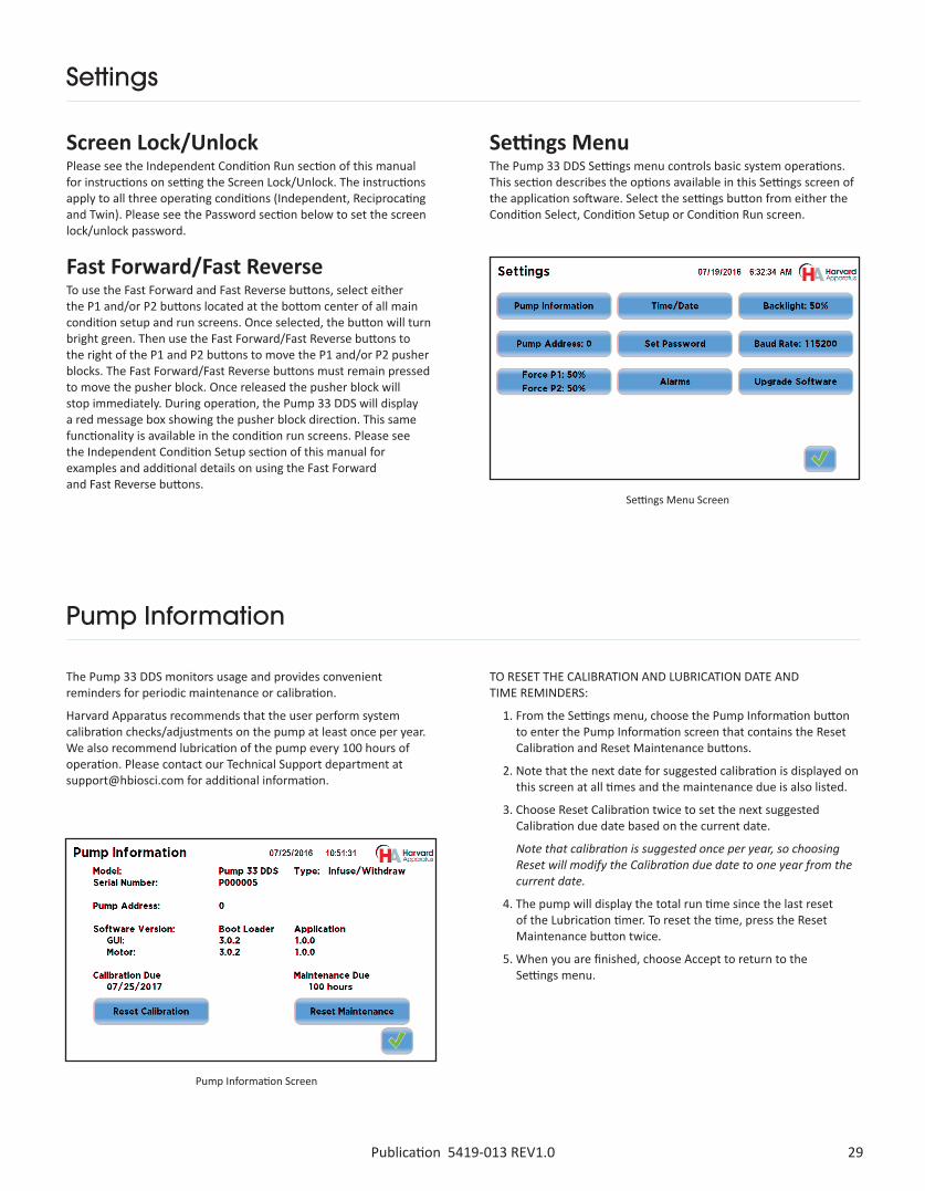
Screen Lock/UnlockPlease see the Independent Condition Run section of this manual for instructions on setting the Screen Lock/Unlock. The instructions apply to all three operating conditions (Independent, Reciprocating and Twin). Please see the Password section below to set the screen lock/unlock password.
Fast Forward/Fast ReverseTo use the Fast Forward and Fast Reverse buttons, select either the P1 and/or P2 buttons located at the bottom center of all main condition setup and run screens. Once selected, the button will turn bright green. Then use the Fast Forward/Fast Reverse buttons to the right of the P1 and P2 buttons to move the P1 and/or P2 pusher blocks. The Fast Forward/Fast Reverse buttons must remain pressed to move the pusher block. Once released the pusher block will stop immediately. During operation, the Pump 33 DDS will display a red message box showing the pusher block direction. This same functionality is available in the condition run screens. Please see the Independent Condition Setup section of this manual for examples and additional details on using the Fast Forward and Fast Reverse buttons.
Settings MenuThe Pump 33 DDS Settings menu controls basic system operations. This section describes the options available in this Settings screen of the application software. Select the settings button from either the Condition Select, Condition Setup or Condition Run screen.
Settings Menu Screen
The Pump 33 DDS monitors usage and provides convenient reminders for periodic maintenance or calibration.
Harvard Apparatus recommends that the user perform system calibration checks/adjustments on the pump at least once per year. We also recommend lubrication of the pump every 100 hours of operation. Please contact our Technical Support department at [email protected] for additional information.
TO RESET THE CALIBRATION AND LUBRICATION DATE AND TIME REMINDERS:
1. From the Settings menu, choose the Pump Information button to enter the Pump Information screen that contains the Reset Calibration and Reset Maintenance buttons.
2. Note that the next date for suggested calibration is displayed on this screen at all times and the maintenance due is also listed.
3. Choose Reset Calibration twice to set the next suggested Calibration due date based on the current date.
Note that calibration is suggested once per year, so choosing Reset will modify the Calibration due date to one year from the current date.
4. The pump will display the total run time since the last reset of the Lubrication timer. To reset the time, press the Reset Maintenance button twice.
5. When you are finished, choose Accept to return to the Settings menu.
Pump Information Screen

Publication 5419-013 REV1.030
Setting Time/Date
The Pump 33 DDS displays the date and time on each screen in the user interface. Built-in battery backups maintain the date and time even if the pump loses power or is unplugged for a period of time.
If it is necessary to set the date and time values, follow the instructions below.
TO SET THE DATE AND TIME DISPLAY:
1. From the Settings menu, choose the Time/Date button to enter the Time/Date screen. To change the Date, select the Date button and enter the Date values using the keypad in the format defined by the date Format button to the right of the Date entry box. You can toggle between MM/DD/YY (Month/Day/Year), DD/MM/YY (Day/Month/Year) and YY/MM/DD (Year/Month/day) display by successive presses of the Date Units button.
2. To change the Time, select the Time button and enter the current time in hh:mm:ss (hours:minutes:seconds) format. Select the Time Format button to toggle between AM, 24 Hour and PM values for the Time.
3. When the Date and Time values are correct, choose the Accept button to save your changes and return to the Settings screen.
Set Date and Time Screen
The user can adjust the backlighting level on the Pump 33 DDS touchscreen to optimize viewing in your specific lighting conditions. On the Settings screen, the Backlight button displays the current setting on the button.
TO MODIFY THE BACKLIGHT LEVEL:
1. From the Settings menu, choose the Backlight button to enter the Set Backlight Level screen.
2. Select the desired preset level value. Values are available in 10% increments.
3. When you have selected the desired backlighting value, choose Accept to save your changes and return to the Settings menu.
Backlight Settings Screen
Screen Backlight Adjustment

31Publication 5419-013 REV1.0
Backlight Settings Screen
Pump Address
The Pump Address value defines a programmable address that can be used in external software applications that will call each Pump 33 DDS pump individually. NOTE: If the Pump chaining feature (see PUMP CHAIN COMMANDS below) is being used, each pump must be assigned a unique address. TO MODIFY THE PUMP ADDRESS:
1. From the Settings menu, choose the Pump Address button to enter the Set Pump Address screen.
2. Type the desired address value using the onscreen number pad. Valid entries are: 00 - 99.
3. When you have entered the desired address value, choose Accept to save your changes and return to the Settings menu.
Pump Address Screen
Baud Rate
To set the Password go to the Settings screen. Press the Set Password button, enter your desired password, up to 6 digits, and press the Accept button. Please write your password down and keep it in a secure location.
For attaching the Pump 33 DDS to an external device using RS-232 serial communications, you can easily adjust the baud rate to optimize communications.
TO ADJUST THE PUMP BAUD RATE:
1. From the Settings menu, choose the Baud Rate button to enter the Set Baud Rate screen.
2. Select the desired preset level value (9600, 19200, 38400, 57600, 115200, 128000, 230400, 256000, 460800 & 921600).
3. When you have entered the desired baud rate, choose Accept to save your changes and return to the Settings menu.
Note: Some computers may not be able to handle the baud rates above 115,000.
Set Password Screen
Baud Rate Screen
Set Password

Publication 5419-013 REV1.032
The Pump 33 DDS Pump Channel 1 (P1) and Pump Channel 2 (P2) motors generate up to 70 lbs of linear force per syringe in operation. This force is sufficient to damage delicate, low-volume syringes, as well as many standard syringes if pumping viscous fluids.
The application software provides controls to allow you to set a maximum force value (calculated as a percentage of the maximum value).
From the Settings menu, choose the Force button to enter the Set Force Level screen.
1. Select the desired value in terms of percentage of maximum force. Independent Condition will allow the user to set a different force for Pump Channel 1 (P1) and Pump Channel 2 (P2). Reciprocating and Twin Conditions only require/allow one force setting for both Pump Channel 1 (P1) and Pump Channel 2 (P2).
2. When you have selected or entered the desired force value, choose Accept to return to the Settings menu.
Force Setting
Force Settings Screens for Reciprocating Condition
Force Settings Screens for Independent Condition Force Settings Screens for Twin Condition
Suggested Force Level Chart for Common Syringes
Suggested Force Level Settings for Common Syringes
Syringe Type/Material Capacity Force Setting Common Manufacturer(s)
Plastic Syringes ≤20 ml 55% BD plastic, Sherwood, Airtite, Terumo>20 ml 100%
Stainless Steel All 100% Harvard Apparatus
Glass/Glass ≤20 ml 25% Cadence (Popper)
>20 ml 35%
Glass/Plastic ≤1000 µl 35% Hamilton, SGE
≤5 ml 55%
>5 ml 100%

33Publication 5419-013 REV1.0
Force Settings Screens for Twin Condition
• Near End-of-Run: This alarm (3 beeps) notifies the operator that a run is near-completion. The default near-completion percentage for this alarm is 75%. Pressing and holding this button brings up a screen where the user may adjust this value based on his or her preferences.
• Power Failure: If power is lost when any motor was running, an alarm will sound once power is restored. Press any button on the screen to silence this alarm.
• Calibration Reminder: This alarm informs the user that the system has reached its scheduled calibration date.
• End-of-Run: An alarm will sound when a run is completed. Touch the message window to silence the alarm.
• Motor Stall: An alarm will sound to notify the operator of any motor stall.
• Button Clicks: A soft beep indicates a positive touch on any button on the screen.
• Maintenance Reminder: This alarm informs the user that the system has reached its 100-hour maintenance check.
• Startup Tones: A short sequence of tones, which are played at powerup.
• System Alarms: Other system alarms indicating unexpected operation.
• Mute All: Selecting this option mutes all audible alarms.
The Pump 33 DDS pump incorporates an Audible Alarm feature to warn the operator about various operating conditions, errors and power outages. The following alarms are user configurable in the Settings section of the application. When selected, the alarm button will turn green and the remaining buttons on the screen are blue. Note that this setting governs whether an audio indicator is sounded for the alarm condition, but does not turn on or off detection or visual notification of the alarm condition.
Audible Alarm Screen
Alarms
External Connections
USB Pinout USB Virtual Driver Installation
When you connect the Pump 33 DDS to a Windows computer for the first time, a driver will need to be installed for the Windows PC to communicate with the Pump 33 DDS. The following section gives an overview on the installation of the Virtual CommPort Driver supplied with the Pump 33 DDS using the Windows 7 operating system. The driver installation procedure may differ based on the version of Windows the user employs.

Publication 5419-013 REV1.034
External Connections
USB Virtual Driver Installation The following section gives an overview on the installation of the Virtual CommPort Driver supplied with the Pump 33 DDS. When you connect the Pump 33 DDS to a Windows computer for the first time, the installation of a USB driver is required on the Windows PC for it to communicate with the Pump 33 DDS. An installer package has been provided on the media (CD) provided with the shipment of the Pump 33 DDS. The Pump 33 DDS driver package is compatible with Windows XP, 7, 8.1, & 10;32 and 64-bit systems. The driver installation procedure may differ based on the version of Windows the user employs. The following installation instructions were created on a PC running Windows 7.
1. Connect the Pump 33 DDS to the Windows computer via USB. Run the file “HBIO Driver Setup.exe” found in the Pump Drivers directory on the media (CD) provided with the Pump 33 DDS.
2. The Harvard Bioscience Driver Installer program popup wizard will appear. Please select “Next” to begin the driver installation.

35Publication 5419-013 REV1.0
External Connections
3. Windows security may prompt you to authorize the installation of the driver. Enable the check box to the left of the text ’Always trust software from “Harvard Bioscience”.’ and click the “Install” button.
4. Once the Pump 33 DDS Windows driver installs, click the Finish button to close the installer.

Publication 5419-013 REV1.036
External Connections
There are two components of the pump software: the Boot Loader, which controls how the system manages updates, and the main Application. Harvard Apparatus may occasionally provide updates to each portion of the software, either individually or as a pair, to add new features and/or improve functionality.
Specific instructions may be supplied with the software update, but the general procedure follows.
Items needed for software update are the “Firmware Updater” program (supplied by Harvard Apparatus) installed on a PC, USB cable connecting the pump to the PC on which “Firmware Updater” is installed and file(s) containing the updated application(s). These files will have a file type of “.srec”.
The general process for software update is:
1. Copy the latest software version to your desktop (format is filename.srec).
2. Disconnect all I/O devices and then connect the pump to a PC using a USB cable.
3. On the pump, press the Settings button, then press the Upgrade Software button.
4. Select the Update Bootloader or Update Application depending on which update is to be performed and then select the Accept button.
5. On the PC, from the CD provided with the pump, open the Firmware Updater Application and click Connect (see below).
Upgrade Software
6. Click Open Update File and browse to the .srec file previously save on your desktop and click Open (see below).

37Publication 5419-013 REV1.0
7. Click the Start Update button (see below).
8. After the update is complete, press Reboot to power cycle the pump (see below).
External Connections

Publication 5419-013 REV1.038
External Connections
RS-232 Pinout
RS-485 Pinout
CAUTION: Do not connect to firewire ports on a PC. Damage may occur to pump and/or PC.
1 2 3 4 5
6 7 8 9
Pin # Signal2 RXD
3 TXD
5 GND
1, 4, 6-9 N/C
Baud Rates:
9600
19200
38400
57600
115200
Word size – 8
Parity – None
Stop Bits – 1
Pump PC
39Publication 5419-013 REV1.0
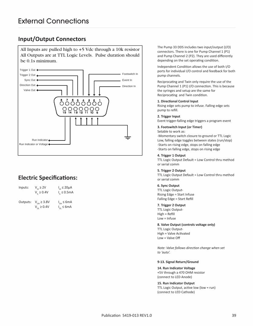
The Pump 33 DDS includes two input/output (I/O) connectors. There is one for Pump Channel 1 (P1) and Pump Channel 2 (P2). They are used differently depending on the set operating condition.
Independent Condition allows the use of both I/O ports for individual I/O control and feedback for both pump channels.
Reciprocating and Twin only require the use of the Pump Channel 1 (P1) I/O connection. This is because the syringes and setup are the same for Reciprocating and Twin condition.
1. Directional Control Input Rising edge sets pump to infuse. Falling edge sets pump to refill.
2. Trigger Input Event trigger-falling edge triggers a program event
3. Footswitch Input (or Timer) Setable to work as: -Momentary switch closure to ground or TTL Logic Low, falling edge toggles between states (run/stop) -Starts on rising edge, stops on falling edge -Starts on falling edge, stops on rising edge
4. Trigger 1 Output TTL Logic Output Default = Low Control thru method or serial comm
5. Trigger 2 Output TTL Logic Output Default = Low Control thru method or serial comm
6. Sync Output TTL Logic Output- Rising Edge = Start Infuse Falling Edge = Start Refill
7. Trigger 2 Output TTL Logic Output- High = Refill Low = Infuse
8. Valve Output (controls voltage only) TTL Logic Output- High = Valve Activated Low = Valve Off
9-13. Signal Return/Ground
14. Run Indicator Voltage +5V through a 470 OHM resistor (connect to LED Anode)
15. Run Indicator Output TTL Logic Output, active low (low = run) (connect to LED Cathode)
Input/Output Connectors
Electric Specifications:
External Connections
Note: Valve follows direction change when set to ‘auto’.
All Inputs are pulled high to +5 Vdc through a 10k resistor All Outputs are at TTL Logic Levels. Pulse duration should be 0.1s minimum.
Trigger 1 Out
Trigger 2 Out
Sync Out
Direction Out
Valve Out
Footswitch In
Event In
Direction In
Run IndicatorRun Indicator or Voltage
Inputs: VIH ≥ 2V IIH ≤ 20µA VIL ≥ 0.4V IIL ≤ 0.5mA
Outputs: VOH ≥ 3.8V IOH ≤ 6mA VOL ≥ 0.4V IOL ≤ 6mA

Publication 5419-013 REV1.040
Pump Chain Commands
The Pump Chain commands allow all pump control information to be managed from an external computer source. These commands can control a series of pumps (up to 100) from a single USB or RS-232 interface on a computer.
Pump 33 DDS commands are communicated to the pump via the USB or RS-232 port interface through a terminal program. In using the Pump Chain commands, you will need to assign each pump in the pump chain a unique address, using the Pump Address screen in the Settings menu or the ‘Address” command. The address range is from 00 to 99. This address value is used to identify which pump is to receive a command and which pump is responding. Configure each pump with its assigned address and baud rate as described in the Settings section of this manual.
Note: To maximize communication speed [as fast as 50 ms rate changes]: (a) prefix commands with the @ symbol to turn off GUI updated (ex: @irate 100 u/m) (b) use the ‘rsave off’ command to turn off write of rate to memory.
Commands may be abbreviated to the first four letters. For example, “address” could be abbreviated “addr”. A space must follow the command if arguments are included.
If the pump being addressed is not the one which the USB cable is plugged into, the one- or two-digit pump address precedes the command without a separator. For example, to set the pump 12 infuse rate to 3.2 ul/min, the command would look like “12irat 3.2 u/m”. If the pump address is less than 10, it does not have to be preceded with a leading 0. Note that if the USB port is used on a single pump (no daisy chaining) or if the USB cable is connected to the pump being addressed, the pump address does not have to be used. The address prefix of the commands is not shown in the following section.In the command list below, the following convention is used:
If the pump is in Poll REMOTE mode, there will be no prompts or carriage returns.
If the pump is in Poll ON mode, an XON character is added after the prompt.
In the following list of commands:
• The general format of the response is <lf>[<addr>]<prompt> unless otherwise noted.
• The [<addr>] field of the general response format will show the address of the responding pump; it will be included if and only if the command was addressed to a pump other than the one which is connected to the USB cable.
• Many commands include a parameter of {a|b|ab}. When this parameter is present, it specifies that the command is to be applied to the first axis only (a), the second axis only (b) or to both axes (ab). In Twin and Reciprocating Condition, any settings for the second axis are implied by the setting for the first axis, so the {a|b|ab} parameter must be excluded.
<axis> <prompt>
:><*T?
Pump motor axis identifier. When present, this will be “A” for axis P1, “B” for axis P2, or “AB” for both P1 and P2 Prompt: a two-character prompt showing the status of each axis of the addressed pump. One of the following characters will be displayed indicating the status of P1, followed by another indicating the status of P2:The pump is idleThe pump is infusingThe pump is withdrawingThe pump stalledThe target was reachedThe pump status is unknown
Required parameterOptional parameterSeparator between parameter choicesNumeric value without preceding zerosNumeric value with preceding zerosA range of valuesCarriage return
Line feedSpacePump address prefix in the format [#]; included only if the pump address is not zero
{ }[ ]|
#
####-#<cr>
<lf><sp><addr>
Error messagesError messages are displayed if the entered command cannot be executed for some reason. The error message will take up two lines with the first line being the message type and the second line describing the error itself. The second line may be up to 80 characters long.
COMMAND ERRORSCommand errors are displayed when the command is unrecognized, entered in the wrong mode, or the state of the pump keeps the command from executing (i.e. using the IRUN command if a limit switch is active).
The command error has the following format:
<lf>[<addr>]Command error: {command}
<lf>[<addr>]<sp><sp><sp>{error message}
<lf>[<addr>]<prompt>

41Publication 5419-013 REV1.0
ARGUMENT ERRORSArgument errors are displayed when a command argument is unrecognized or missing. The argument in question will be displayed except in the case of missing arguments.
The argument error has the following format:
<lf>[<addr>]Argument error: [bad argument]
<lf>[<addr>]<sp><sp><sp>{error message}
<lf>[<addr>]<prompt>
RANGE ERRORSRange errors are displayed when a numeric argument is out of range. The argument in question will be displayed.
The range error has the following format:
<If>[<addr>]Range error: {bad argument}
<If>[<addr>]<sp><sp><sp>{error message}
<If>[<addr>]<prompt>
SYSTEM COMMANDS ADDRESS
Command format: address[<sp>[0-99]] Query response to “address”: <lf>[<addr>]{address} <lf>[<addr>]<prompt> Query response to “address {new addr}”: <lf>[<addr>][<prompt>] Examples: address address<sp>0
BAUDSets or displays the RS232 port baud rate. Valid baud rates are 9600, 19200, 38400, 57600, 115200, 128000, 230400, 256000, 460800, and 921600. Note that some computers may not be able to handle baud rates above 115200. Command format: baud[<sp> 9600 | 19200 | 38400 | 57600 | 115200 | 128000 | 230400 | 256000 | 460800 | 921600] Query response to “baud”: <lf>[<baud>]<promt> Query response to “baud {new baud rate}”: <lf>Please set your baud rate now <If>[<addr>]<prompt> Notes: If this command is entered via RS232, the prompt is displayed at the previous baud rate and then the baud rate is changed. Examples: baud baud<sp>921600
Pump Chain Commands
Sets or displays the pump address. Valid range is 0 to 99.
Publication 5419-013 REV1.042
BRIGHTSets or displays the backlight brightness level in percent. Valid range is 0 to 100. Note that specifying 0 will turn the backlight off so that the screen will not be visible. Command format: bright[<sp>0-100] Query response to “bright”: <lf>[<addr>]{#%} <lf>[<addr>]<prompt> Query response to “bright {new bright level}”: <lf>[<addr>]<prompt> Example: bright bright<sp>100
CONDITIONSets or displays the Operating Condition setting. Condition may be set to Twin (in which the second axis performs identically to the first axis, using the same mode, syringe, force, rates, direction and targets), Reciprocating (in which the second axis performs identically to the first, except the motor direction is reversed), or Independent (in which parameters for the second axis may be set to differ from those of the first axis). Command format: condition[<sp>{Twin|T|Reciprocating|R|Independent|I}] Query response to “condition”: <lf>[<addr>]{Twin|Reciprocating|Independent} <lf>[<addr>]<prompt> Query response to “cond {new condition}”: <lf>[<addr>]<prompt> Example: condition condition<sp>T condition<sp>Independent
CONFIGSets or displays the pump configuration. In response to this command, the pump will display a list of mechanical configuration variables and their current settings. Except in instances of custom configurations, these values are not expected to require changes. Command format: config[<sp><axis>]
ECHOSets or displays the RS232/USB echo state. Valid states are on or off. Command format: echo[<sp>[on|off]] Query response to “echo”: <lf>[<addr>]{Off|On} <lf>[<addr>]<prompt> Query response to “echo {Off|On}”: <lf>[<addr>]<prompt> Example: echo<sp>off Note: If polling mode is set to “Remote”, the response to “echo” will be: <lf>[<addr>]Off in remote polling mode
FASTAllows fast-forward/fast-reverse motion of one or both axes. The “i” parameter initiates fast motion in the
“Infuse” direction (left to right if you are facing the pump); the “w” parameter initiates fast motion in the “Withdraw” or “Refill” direction (right to left); the “s” parameter stops any fast-forward or fast-reverse motion that is underway. Command format: fast<sp><axis><sp>{i|w|s}
Pump Chain Commands

43Publication 5419-013 REV1.0
FORCESets or displays the infusion force level in percent. Valid range is 1 to 100.
Command format (Independent Condition): force<sp>{a|b|ab}[<sp>[1-100]] Query response (the first line will be repeated for each requested axis): <lf>[<addr>]<axis>#% <lf>[<addr>]<prompt> Command format (Twin or Reciprocating Condition): force[<sp>1-100] Query response: <lf>[<addr>]#% <lf>[##]<prompt> Set New Value response (any Condition): <lf>[<addr>]<prompt> Example (Independent Condition): Axis A: force<sp>a<sp>90 Axis A and B with the same force Force<sp>ab<sp>90 Axis A and B with different forces must be two separate commands Example (Twin or Reciprocating Condition): force<sp>90
FTSWITCHSets or displays the footswitch setting. The footswitch may be used in a toggle on or off mode (momentary), a press to run mode (falling), or a release to run mode (rising).
Command format (Independent Condition): ftswitch<sp>{a|b|ab}[<sp>[m|r|f]] Query response (the first line will be repeated for each requested axis): <lf>[<addr>]<axis><sp>Momentary <lf>[<addr>]<prompt>
or:
<lf>[<addr>]<axis><sp>Active high <lf>[<addr>]<prompt>
or:
<lf>[<addr>]<axis><sp>Active low <lf>[<addr>]<prompt> Command format (Twin or Reciprocating Condition): ftswitch><sp>[m|r|f] Query response: <lf>[<addr>]<sp>Momentary <lf>[<addr>]<prompt>
or:
<lf>[<addr>]<sp>Active high <lf>[<addr>]<prompt>
or:
<lf>[<addr>]<sp>Active low <lf>[<addr>]<prompt> Set New Value response (any Condition): <lf>[<addr>]<prompt> Example (Independent Condition): ftswitch<sp>a<sp>m Example (Twin or Reciprocating Condition): ftswitch<sp>m
NEORSets or displays the near end-of-run alarm percentage setting for one or both axes. Valid range is 1 to 99.
Command format (Independent Condition): neor<sp>{a|b|ab}[<sp>{percent}] Query response (the first line will be repeated for each requested axis): <lf>[<addr>]<axis><sp>#% <lf>[<addr>]<prompt> Set New Value response (any Condition): <lf>[<addr>]<prompt> Example (Independent Condition): neor<sp>ab<sp>75 Example (Twin or Reciprocating Condition): neor<sp>75
Pump Chain Commands

Publication 5419-013 REV1.044
POLLSets or displays the polling mode state.
When polling mode is off, prompts are displayed when an event happens, such as a target being reached.
When polling mode is on, prompts are not displayed when an event happens, and an XON character is output when the pump is ready for another command.
When polling mode is remote, the following occurs:
• Prompts are not displayed
• Echo is forced off and the echo command is illegal Command format: poll[<sp>[on|off|remote]] Default state = off Query response: <lf>[<addr>]Off <lf>[<addr>]<prompt> or: <lf>[<addr>]On <lf>[<addr>]<prompt><xon> or: [<addr>] Remote Examples: poll poll<sp>off
RSAVETurns On or Off saving rate changes to memory. Without the On/Off parameter, the current setting is displayed. With the parameter, continually writing rate changes to memory is turned on or off accordingly.
This command should be used when sending commands quickly to avoid damage to the pump memory.
Command format: rsave[<sp>{On|Off}] Query response: <lf>[<addr>]{On|Off} <lf>[<addr>]<prompt>
Pump Chain Commands
TIME Sets or displays the date and time.
Command format: time[<sp>{mm/dd/yy|dd/mm/yy|yy/mm/dd}{<sp>}{hh:mm:ss}] Query response: <lf>[<addr>]##/##/## ## ##:##:## #M <lf>[<addr>]<prompt> The date order format is dependent on the settings made when setting the date from the touch screen. The time format is 24 hours. Example 1 (display current date and time): time Example 2 (set date and time): time<sp>01/02/16<sp>13:14:15 Note: If date format has been set to MM/DD/YY, this command sets the time and date to 13:14:15 (01:14:15 PM) on January 2, 2016. If date format has been set to DD/MM/YY, this command sets the time and date to 13:14:15 (01:14:15 PM) on February 1, 2016.
If date format has been set to YY/MM/DD, this command sets the time and date to 13:14:15 (01:14:15 PM) on February 16, 2001.

45Publication 5419-013 REV1.0
TOUCHGets or sets the touchscreen On/Off status. This command can be used to disable and re-enable touchscreen input. If the {on|off} parameter is omitted, the current On/Off setting is returned.
Command format: touch[<sp>{on|off}] Query response for “touch”: <lf>[<addr>]{On|Off} <lf>[<addr>]<prompt> Response for “touch {on|off}”: <lf>[<addr>]<prompt>
VALVEDisplays or sets the valve state. When the valve is set to auto, the motor direction determines the valve state. When set to auto, OFF = Infuse and ON = Refill.
Command format (Independent Condition): valve<sp>{a|b|ab}[on|off|auto] Query response: <lf>[<addr>]<axis><sp>On
or:
<lf>[<addr>]<axis><sp>Off
or: (one of these three lines is shown for each requested axis) <lf>[<addr>]<axis><sp>Automatic <lf>[<addr>]<prompt> (this line follows the last axis displayed) Example: valve<sp>ab<sp>auto Command format (Reciprocating or Twin Condition): valve<sp>[on|off|auto] Query response:
<lf>[<addr>]On
or:
<lf>[<addr>]Off (one of these three lines is shown)
or:
<lf>[<addr>]Automatic <lf>[<addr>]<prompt> (this line follows the displayed axis info) Example: valve<sp>auto
VERBOSESpecify the level of detail displayed in error messages.
When Verbose is set to On, full two-line error messages will be displayed for errors.
When Verbose is set to Msg, a one-line error messages will be displayed for errors.
When Verbose is set to Off, no error messages will be displayed, but a “?” will be displayed for errors.
When Verbose is set to None, no error messages will be displayed.
Note: Unlike most settings, the “verbose” setting is not retained through power cycles. It defaults to On for each power-up. Command format: verbose<sp>[on|off|msg|none] Query response: <lf>[<addr>]{On|Off|Message|None} <lf>[<addr>]<prompt> Examples: verbose verbose<sp>On
VERDisplays the short version string.
Command format: ver Query response: <lf>[<addr>]Pump 33 DDS #.#.# <lf>[<addr>]<prompt>
VERSIONDisplays the full version string.
Command format: version Query response: <lf>[<addr>]Pump 33 DDS <lf>[<addr>]Display boot loader: #.#.# <lf>[<addr>]Display application: #.#.# <lf>[<addr>]Motor boot loader: #.#.# <lf>[<addr>]Motor application: #.#.# <lf>[<addr>]Serial number: P###### <lf>[<addr>]<prompt>
Pump Chain Commands

Publication 5419-013 REV1.046
Pump Chain Commands
SYRSets or displays the selected syringe setting for one or both axes. Quick start only. Valid 3-character manufacturer codes are shown in the table below. Typing ‘syr’ with no arguments or with only the axis specifier displays the current syringe setting(s). Typing ‘syr<sp>?’ or ‘syr<sp>{a|b|ab}<sp>?’ displays a list of manufacturers with their associated 3-letter code: see table below. Typing ‘syr<sp><code><sp>?’ or ‘syr<sp>{a|b|ab}<sp><code><sp>?’ shows a list of syringe sizes associated with the specified manufacturer. This includes an index, a volume, and a diameter for each syringe available in manufacturer list <code>. Typing ‘syr<sp><code><sp><index>’ or ‘syr<sp>{a|b|ab}<sp><code><sp><index>’ selects the syringe in index <index> of the list of syringes associated with the manufacturer determined by <code>.
Command format (Independent Condition): syr<sp>{a|b|ab}[<sp>[?|<code>[<sp>{?|index}]]] Example 1: syr<sp>ab Query response to syr<sp>{a|b|ab}:
(Show syringe that has been selected for axis a, or b, or list both a & b)
<lf>[<addr>]<axis><sp>{mfr|Custom},<sp>{vol}<sp>[ml|ul], <sp>{diam}<sp>mm (this line is displayed for each req axis)
<lf>[<addr>]<prompt> Example 2: syr<sp>ab<sp>? Query response to syr<sp>{a|b|ab}<sp>?: (Show syringe manufacturers that may be selected for axis a, or b, or list both a & b) for each axis requested:
<lf>[<addr>]<axis> <lf>[<addr>]{code}<sp>{manufacturer}(one line is displayed for each manufacturer) <lf>[<addr>]<prompt> Example 3: syr<sp>ab<sp>sst<sp>? Query response to syr<sp>{a|b|ab}<sp><code><sp>?:
(Show syringes from manufacturer with code <code> that may be selected for axis a, or b, or show info for both a & b) for each axis requested:
<lf>[<addr>]<axis> <lf>[addr] # Volume Diameter<cr> <lf>[addr]<index>:<sp><vol><sp><ul|ml><sp><diam> (one line is displayed for each syringe) <lf>[<addr>]<prompt>
SYRINGE COMMANDS Command format (Independent Condition): syr<sp>{a|b|ab}[<sp>[?|<code>[<sp>{?|index}]]] Example 1: syr<sp>ab Query response to syr<sp>{a|b|ab}:(Show syringe that has been selected for axis a, or b, or list both a & b)<lf>[<addr>]<axis><sp>{mfr|Custom},<sp>{vol}<sp>[ml|ul], <sp>{diam}<sp>mm (this line is displayed for each req axis)<lf>[<addr>]<prompt> Example 2: syr<sp>ab<sp>? Query response to syr<sp>{a|b|ab}<sp>?: (Show syringe manufacturers that may be selected for axis a, or b, or list both a & b) for each axis requested:<lf>[<addr>]<axis> <lf>[<addr>]{code},<sp>{manufacturer}(one line is displayed for each manufacturer) <lf>[<addr>]<prompt> Example 3: syr<sp>ab<sp>sst<sp>? Query response to syr<sp>{a|b|ab}<sp><code><sp>?:(Show syringes from manufacturer with code <code> that may be selected for axis a, or b, or show info for both a & b) for each axis requested:<lf>[<addr>]<axis> <lf>[addr] # Volume Diameter<cr> <lf>[addr]<index>:<sp><vol><sp><ul|ml><sp><diam> (one line is displayed for each syringe) <lf>[<addr>]<prompt> Example 4: syr<sp>ab<sp>sst<sp>1 Query response to syr<sp>{a|b|ab}<sp><code><sp><index>: (Set syringe for listed axes to syringe with index <index> in table for manufacturer with code <code>) <lf>[<addr>]<prompt>
air Air-Tite, HSW Norm-Jectbdg Becton Dickinson, Glass (all types)bdp Becton Dickinson, Plasti-pakcad Cadence Science, Micro-Mate Glasscma CMA Microdialysish07 Hamilton 700, Glassh10 Hamilton 1000, Glassh17 Hamilton 1700, Glassh70 Hamilton 7000, Glasshos Hoshiils ILS, GLassnip Niprosge SGE (Scientific Glass Engineering)smp Sherwood-Monojet, Plasticsst Stainless Steeltej Terumo Japan, Plastictop Top

47Publication 5419-013 REV1.0
Pump Chain Commands
GANGSets or displays the syringe count. The Gang command is not valid in Independent and Reciprocating Condition. In Twin Condition, Gang may be set to either 1 or 2. If an attempt is made to set the Gang count to higher than the allowed value, the response will be:
<lf>[<addr>]Range error:<sp>{requested gang setting} <lf>[<addr>]<sp><sp><sp>Syringe count out of range of <min> to <max>. Command format (Twin Condition): gang[<sp>{syringe count} Query response to gang: <lf>[<addr>]# syringes<cr> <lf>[<addr>]<prompt> Query response to gang<sp>{syringe count}: <lf>[<addr>]<prompt> Example: gang<sp>ab<sp>1
SVOLUMESets or displays syringe volume.
Command format (Independent Condition): svolume<sp>{a|b|ab}[<sp>{syringe volume} {ul|ml}] Query response to svolume<sp>{a|b|ab} <lf>[<addr>]<axis># xl<cr> (displays one line per requested axis) <lf>[<addr>]<prompt> (displayed after last axis line) Query response to svolume <sp>{a|b|ab}<sp>{syringevolume {ul|ml}} <lf>[<addr>]<prompt> Command format (Reciprocating or Twin Condition): svolume[<sp>{syringe volume} {ul|ml}] Query response to svolume <lf>[<addr>]# xl<cr> <lf>[<addr>]<prompt> Query response to svolume<sp>{syringevolume {ul|ml}} <lf>[<addr>]<prompt> Examples: svolume<sp>ab<sp>5<sp>ul svolume<sp>10<sp>ml
DIAMETERSets or displays the syringe diameter in mm.
Command format (Independent Condition): diameter<sp>{a|b|ab}[<sp>{syringe diameter}] Query response to diameter<sp>{a|b|ab}: <lf>[<addr>]<axis><sp># (displays one line per requested axis) <lf>[<addr>]<prompt> Query response to diameter<sp>{a|b|ab}<sp>[{syringe diameter}]: <lf>[<addr>]<prompt> Command format (Reciprocating or Twin Condition): diameter[<sp>{syringe diameter}] Query response to diameter: <lf>[<addr>]# mm <lf>[<addr>]<prompt> Query response to diameter<sp>{syringe diameter}: <lf>[<addr>]<prompt> Example: diameter<sp>a<sp>4.85

Publication 5419-013 REV1.048
RUN COMMANDS RATE COMMANDS
IRUNRuns the pump(s) in the infuse direction if the current settings allow.
RRUNRuns the pump(s) in the opposite direction if the current settings allow.
Command format (Independent Condition): irun<sp>{a|b|ab} Command format (Reciprocating or Twin Condition): irun
Command format (Independent Condition): rrun<sp>{a|b|ab} Command format (Reciprocating or Twin Condition): rrun
RUNRuns the motor(s) at their current rates in their current directions. This can be used to restart both axes at the same time. For example, if a pump is in Independent condition, axis P1 has started infusing, axis P2 has started refilling, and then motors are paused, typing “run ab” will restart both motors at the same time, in their original directions (axis P1 infusing and axis P2 refilling).
STOPStops the pump(s).
WRUNRuns the pump(s) in the withdraw direction if the current settings allow. Quick Start mode only.
Command format (Independent Condition): run<sp>{a|b|ab} Command format (Reciprocating or Twin Condition): run
Command format (Independent Condition): stop<sp>{a|b|ab} Command format (Reciprocating or Twin Condition): stop
Command format (Independent Condition): wrun<sp>{a|b|ab} Command format (Reciprocating or Twin Condition): wrun
CRATEDisplays the current rate(s) at which the motor(s) is/are running. A valid response is returned only in dynamic situations (while the pump is running).
NOTE: In the descriptions for Rate commands, the text “xl/xxx” is used as a placeholder to indicate the actual flow rates. For commands requiring rate units, use the following format:
{ml|ul|nl|pl}/{hr|min|sec} which may be abbreviated to: {m|u|n|p}[/]{h|m|s}
Ex: m/m or mm= milliliter/minute n/s or ns= nanoliter/second
Command format (Independent Condition): crate<sp>{a|b|ab} Query response:
<lf>[<addr>]<axis> Infusing at # xl/xxx or: (one of these two lines is shown for each requested axis) <lf>[<addr>]<axis> Withdrawing at # xl/xxx <lf>[<addr>]<prompt> (this line follows the info for the last displayed axis) Command format (Reciprocating or Twin Condition): crate Query response: <lf>[<addr>] Infusing at # xl/xxx or: (one of these two lines is shown) <lf>[<addr>] Withdrawing at # xl/xxx <lf>[<addr>]<prompt> (this line follows the axis info line)
Pump Chain Commands

49Publication 5419-013 REV1.0
IRATESets or displays the infusion rate. The rate argument may be replaced with “max” or “min” to set the rate to the maximum or minimum rate, respectively. “lim” may be used to display the range limits.
Command format (Independent Condition): irate<sp>{a|b|ab}[<sp>max|min|lim|<rate><sp>{rate units}] Query response: <lf>[<addr>]<axis># xl/xxx (displays one line per requested axis) <lf>[<addf>]<prompt> or (if “lim” argument is used): <lf>[<addr>]<axis> # xl/xxx to # xl/xxx (displays one line per requested axis) <lf>[<addr>]<prompt> Example: itrate<sp>ab<sp>10<sp>ml/min Command format (Reciprocating or Twin Condition): irate[<sp>[max|min|lim|<rate><sp>{rate units}]] Query response: <lf>[<addr>]# xl/xxx <lf>[<addr>]<prompt> or (if “lim” argument is used): <lf>[<addr>]# xl/xxx to # xl/xxx <lf>[<addr>]<prompt> Example: itrate<sp>10<sp>ml/min
Pump Chain Commands
ITRATESets or displays the target infusion rates for ramping. The rate argument may be replaced with “max” or “min” to set the maximum or minimum rate, respectively. “lim” may be used to display the range limits.
Command format (Independent Condition): itrate<sp>{a|b|ab}[<sp>max|min|lim|<rate><sp>{rate units}] Query response: <lf>[<addr>]<axis> # xl/xxx (displays one line per requested axis) <lf>[<addr>]<prompt> or (if “lim” argument is used): <lf>[<addr>]<axis> # xl/xxx to # xl/xxx (displays one line per requested axis) <lf>[<addr>]<prompt> Example 1 (Independent Condition): itrate<sp>ab<sp>lim Query response: <lf>[<addr>]A: # xl/xxx to # xl/xxx <lf>[<addr>]B: # xl/xxx to # xl/xxx <lf>[<addr>]<prompt> Example 2 (Independent Condition): itrate<sp>ab<sp>max Query response: <lf>[<addr>]<prompt> Example 3 (Independent Condition): itrate<sp>ab<sp>10<sp>ml/min Query response: <lf>[<addr>]A: 10 ml/min <lf>[<addr>]B: 10 ml/min <lf>[<addr>]<prompt> Command format (Reciprocating or Twin Condition): itrate[<sp>max|min|lim|<rate><sp>{rate units}] Example: itrate<sp>10<sp>ml/min

Publication 5419-013 REV1.050
RATESets or displays the rate for the current direction (infuse or withdraw) for the specified axis. It can be used in place of “IRATE” if the current direction for the given axis is Infuse or “WRATE” if the current direction is Withdraw. Quick Start mode only. The rate argument may be replaced with “max” or “min” to set the rate to the maximum or minimum rate, respectively. “lim” may be used to display the range limits.
Command format (Independent Condition): rate<sp>{a|b|ab}<sp>[max|min|lim|<rate><sp>{rate units}] Query response: <lf>[<addr>]<axis> # xl/xxx (displays one line per requested axis) <lf>[<addr>]<prompt> or (if “lim” argument is used): <lf>[<addr>]<axis> # xl/xxx to # xl/xxx (displays one line per requested axis) <lf>[<addr>]<prompt> Example: rate<sp>ab<sp>10<sp>ml/min Command format (Reciprocating or Twin Condition): rate[<sp>max|min|lim|<rate><sp>{rate units}] Query response: <lf>[<addr>]# xl/xxx <lf>[<addr>]<prompt> or (if “lim” argument is used): <lf>[<addr>]# xl/xxx to # xl/xxx <lf>[<addr>]<prompt> Example: rate<sp>10<sp>ml/min
Pump Chain Commands
TRATESets or displays the target infusion rates for ramping for the current direction for the specified axis. It can be used in place of “ITRATE” if the current direction for the given axis is Infuse or “WTRATE” if the current direction is Withdraw. The rate argument may be replaced with “max” or “min” to set the maximum or minimum rate, respectively. “lim” may be used to display the range limits.
Command format (Independent Condition): trate<sp>{a|b|ab}[<sp>max|min|lim|<rate><sp>{rate units}] Query response: <lf>[<addr>]<axis> # xl/xxx(displays one line per requested axis) <lf>[<addr>]<prompt> or (if “lim” argument is used): <lf>[<addr>]<axis> # xl/xxx to # xl/xxx (displays one line per requested axis) <lf>[<addr>]<prompt> Example 1 (Independent Condition): trate<sp>ab<sp>lim Query response: <lf>[<addr>]A: # xl/xxx to # xl/xxx <lf>[<addr>]B: # xl/xxx to # xl/xxx <lf>[<addr>]<prompt> Example 2 (Independent Condition): trate<sp>ab<sp>max Query response: <lf>[<addr>]<prompt> Example 3 (Independent Condition): trate<sp>ab<sp>10<sp>ml/min Query response: <lf>[<addr>]A: 10 ml/min <lf>[<addr>]B: 10 ml/min <lf>[<addr>]<prompt> Command format (Reciprocating or Twin Condition): trate[<sp>max|min|lim|<rate><sp>{rate units}] Example: trate<sp>10<sp>ml/min

51Publication 5419-013 REV1.0
WRATESets or displays the withdraw rate. The rate argument may be replaced with “max” or “min” to set the rate to the maximum or minimum rate, respectively. “lim” may be used to display the range limits.
Command format (Independent Condition): wrate<sp>{a|b|ab}<sp>[max|min|lim|<rate><sp>{rate units}] Query response: <lf>[<addr>]<axis> # xl/xxx (displays one line per requested axis) <lf>[<addr>]<prompt> or (if “lim” argument is used): <lf>[<addr>]<axis> # xl/xxx to # xl/xxx (displays one line per requested axis) <lf>[<addr>]<prompt> Example: wrate<sp>ab<sp>10<sp>ml/min Command format (Reciprocating or Twin Condition): wrate[<sp>max|min|lim|<rate><sp>{rate units}] Query response: <lf>[<addr>]# xl/xxx <lf>[<addr>]<prompt> or (if “lim” argument is used): <lf>[<addr>]# xl/xxx to # xl/xxx <lf>[<addr>]<prompt> Example: wrate<sp>10<sp>ml/min
Pump Chain Commands
WTRATESets or displays the target withdraw rates for ramping. The rate argument may be replaced with “max” or “min” to set the rate to the maximum or minimum rate, respectively. “lim” may be used to display the range limits.
Command format (Independent Condition): wtrate<sp>{a|b|ab}[<sp>max|min|lim|<rate><sp> {rate units}] Query response: <lf>[<addr>]<axis> # xl/xxx (displays one line per requested axis) <lf>[<adr>]<prompt> or (if “lim” argument is used): <lf>[<addr>]<axis> # xl/xxx to # xl/xxx (displays one line per requested axis) <lf>[<addr>]<prompt> Example: wtrate<sp>ab<sp>10<sp>ml/min Command format (Reciprocating or Twin Condition): wtrate[<sp>max|min|lim|<rate><sp>{rate units}] Query response: <lf>[<addr>]# xl/xxx <lf>[<addr>]<prompt> or (if “lim” argument is used): <lf>[<addr>]# xl/xxx to # xl/xxx <lf>[<addr>]<prompt> Example: wtrate<sp>10<sp>ml/min

Publication 5419-013 REV1.052
VOLUME COMMANDS
CIVOLUMEClears the infused volume.
CTVOLUMEClears the target volume.
CVOLUMEClears both the infused and withdrawn volumes.
CWVOLUMEClears the withdrawn volume.
Command format (Independent Condition): civolume<sp>{a|b|ab} Command format (Reciprocating or Twin Condition): civolume
Command format (Independent Condition): ctvolume<sp>{a|b|ab} Command format (Reciprocating or Twin Condition): ctvolume
Command format (Independent Condition): cvolume<sp>{a|b|ab} Command format (Reciprocating or Twin Condition): cvolume
Command format (Independent Condition): cwvolume<sp>{a|b|ab} Command format (Reciprocating or Twin Condition): cwvolume
IVOLUMEDisplays the infused volume.
Command format (Independent Condition): ivolume<sp>{a|b|ab} Query response: <lf>[<addr>]<axis># xl (displays one line per requested axis) <lf>[<addr>]<prompt> (displayed after last axis line) Command format (Reciprocating or Twin Condition): ivolume Query response: <lf>[<addr>]# xl <lf>[<addr>]<prompt>
Pump Chain Commands
WVOLUMEDisplays the withdrawn volume.
Command format (Independent Condition): wvolume<sp>{a|b|ab} Query response: <lf>[<addr>]<axis> # xl (displays one line per requested axis) <lf>[<addr>]<prompt> Command format (Reciprocating or Twin Condition): wvolume Query response: <lf>[<addr>]# xl <lf>[<addr>]<prompt>
TVOLUMESets or displays the target volume.
Command format (Independent Condition): tvolume<sp>{a|b|ab}[<sp>{target volume}<sp>{volume units}] Query response to tvolume<sp>{a|b|ab}: <lf>[<addr>]<axis> Target volume not set or (displays one line per requested axis) <lf>[<addr>]<axis> # xl <lf>[##]<prompt> (displayed after last axis line) Query response to tvolume<sp>{a|b|ab}<sp>[{target volume}<sp>{volume units}]: <lf>[<addr>]<prompt> Command format (Reciprocating or Twin Condition): tvolume[<sp>{target volume}<sp>{volume units}] Query response to tvolume: <lf>[<addr>]Target volume not set or <lf>[<addr>]# xl <lf>[<addr>]<prompt> Query response to tvolume<sp>[{target volume}<sp>{volume units}]: <lf>[<addr>]<prompt> Examples: tvolume<sp>ab<sp>5<sp>ul tvolume<sp>10<sp>ml

53Publication 5419-013 REV1.0
Pump Chain Commands
TIME COMMANDS
CITIMEClears the infused time.
CWTIMEClears the withdrawn time.
CTTIMEClears the target time.
CTIMEClears both the infused and withdrawn times.
Command format (Independent Condition): citime<sp>{a|b|ab} Command format (Reciprocating or Twin Condition): citime
Command format (Independent Condition): cwtime<sp>{a|b|ab} Command format (Reciprocating or Twin Condition): cwtime
Command format (Independent Condition): cttime<sp>{a|b|ab} Command format (Reciprocating or Twin Condition): cttime
Command format (Independent Condition): ctime<sp>{a|b|ab} Command format (Reciprocating or Twin Condition): ctime
ITIMEDisplays the infused time.
TTIMESets or displays the target time.
WTIMEDisplays the withdrawn time.
Command format (Independent Condition): wtime<sp>{a|b|ab} Query response: <lf>[##:]<axis># or (displays one line per requested axis) <lf>[##:]<axis>##:##:## <lf>[##]<prompt> (displayed after last axis line) Command format (Reciprocating or Twin Condition): wtime Query response: <lf>[##:]# seconds <lf>[##]<prompt> or: <lf>[##:]##:##:## <lf>[##]<prompt>
Command format (Independent Condition): itime<sp>{a|b|ab} Query response: <lf>[<addr>]<axis># (time given in seconds) or (displays one line per requested axis) <lf>[<addr>]<axis>##:##:## (time in HH:MM:SS format) <lf>[<addr>]<prompt> (displayed after last axis line) Command format (Reciprocating or Twin Condition): itime Query response: <lf>[<addr>]# <lf>[<addr>]<prompt> or: <lf>[<addr>]##:##:## <lf>[<addr>]<prompt>
Command format (Independent Condition): ttime[<sp>{a|b|ab}<sp>{target time}] Query response to ttime<sp>{a|b|ab}: <lf>[<addr>]<axis> Target time not set or <lf>[<addr>]<axis> # (displays one of these three lines per req axis) or <lf>[<addr>]<axis> ##:##:## <lf>[<addr>]<prompt> (displayed after last axis line) Query response to ttime<sp>{a|b|ab}<sp>[{target time}]: <lf>[<addr>]<prompt> Command format (Reciprocating or Twin Condition): ttime[<sp>{target time}] Query response to ttime: <lf>[<addr>]Target time not set or <lf>[<addr>] # (displays one of these lines) or <lf>[<addr>] ##:##:## <lf>[<addr>]<prompt> Query response to ttime<sp>[{target time}]: <lf>[##]<prompt> Examples: ttime<sp>ab<sp>30<sp>sec ttime<sp>10<sp>min

Publication 5419-013 REV1.054
Pump Chain Commands
DIGITAL I/O COMMANDS
INPUTReads and displays the trigger input port status.
Command format (Independent Condition): input[<sp>{a|b|ab}] Query response to “input<sp>{a|b|ab}”: <lf>[<addr>]<axis><sp>Low|High <lf>[<addr>]<prompt> (displayed after last axis line) Command format (Reciprocating or Twin Condition): input Query response: <lf>[<addr>]<axis><sp>Low <If>[<addr>]<prompt> (displayed after last axis line) or (displays one line per requested axis) <lf>[<addr>]<axis><sp>High <lf>[<addr>]<prompt>
OUTPUTSets the level on one of the output ports.
Command format (Independent Condition): output<sp>{a|b|ab}<sp>{1|2}<sp>{high|low} Command format (Reciprocating or Twin Condition): output<sp>{1|2}<sp>{high|low} Example: output<sp>ab<sp>1<sp>high
SYNCSets the level on the sync port.
Command format (Independent Condition): sync<sp>{a|b|ab}<sp>{high|low} Command format (Reciprocating or Twin Condition): sync<sp>{high|low} Examples: sync<sp>ab<sp>high sync<sp>a<sp>low
INTERNAL COMMANDS
STATUSDisplays the raw status for use with a controlling computer Command format (Independent Condition: status
Query Response:
• Flag one (<MDn>) is the motor direction and will be “i or I” if the pump is infusing and “w or W” if the pump is withdrawing. If the letter is lower case, the pump motor is idle. If upper case, the pump motor is running.
• Flag two (<Ln>) is the limit switch status. If the infuse limit switch was hit, “i or I” is displayed. If the withdraw limit switch was hit, “w or W” is displayed. If no limit switch was hit or the pump does not have limit switches, “.” is displayed.
• Flag three (<Sn>) is the stall status and will be “S” if the pump has stalled. Otherwise it will be “.”.
• Flag four (<In>) is the trigger input state and will be “T” if high and “.” if low.
• Flag five (<DPn>) is the direction port state and will be “I” for infuse and “W” for withdraw.
• Flag six (<Tn>) is the target reached status. It will be “T” if the target time or volume was reached,or “.” if not.
The output is data elements for each axis, separated by spaces and terminated by a carriage return / linefeed pair. The data for each axis consists of three integer fields and one flag field, all separated by spaces. For each axis, the first integer (<RATEn>) is the current rate in femtoliters per second, the second integer (<TIMEn >) is the infuse time in milliseconds (granularity of 1 millisecond), and the third integer (<VOLn>) is the infused volume in femtoliters. All three values are for the current direction.
Each axis flag field consists of six flags:
<lf>[<addr>]<RATEA><sp><TIMEA><sp><VOLA><sp><MDA><LA><SA><IA><DPA><TA><sp>
<RATEB><sp><TIMEB><sp><VOLB><sp><MDB><LB><SB><IB><DPB><TB><sp><cr>
<lf>[<addr>]<RATEA><sp><TIMEA><sp><VOLA><sp><MDA><LA><SA><IA><DPA><TA><If>[<addr>]<RATEB><sp><TIMEB><sp><VOLB><sp><MDB><LB7><SB><IB><DPB><TB>

55Publication 5419-013 REV1.0
Pump 33 DDS series pumps require no special maintenance other than keeping them clean by avoiding accidental spills of pumped material. Refer to the chemical compatibility chart below for specific chemical resistance information. The two guide rods and the lead screw should be sparingly lubricated periodically; every 100 hrs the pump will remind you. The guide rods and the lead screw should be lubricated with Super Lube Synthetic Grease provided with the pump.
To clean the exterior surfaces, use a lint-free cloth to remove loose dust. Use care to avoid scratching the clear display window. For more efficient cleaning, use a soft cloth dampened [not soaked] with water, an aqueous solution of 75% isopropyl alcohol, or a mild detergent.
Maintenance
Maintenance, Battery Replacement, and Troubleshooting
1. Remove screw and swing cover to the side
2. Slide battery out from under clip.
3. Install Lithium Coin Battery: 3V, 16mm CR1620 (Harvard Part No. 5155-288 or equivalent) by sliding under clip with position side facing out.
4. Reset the Date & Time. See Settings/Date & Time.
5. Reset the calibration due date. See Settings/Pump Information.
Battery Replacement
Caution: Use only same type & rated battery. Observe polarity when installing.

Publication 5419-013 REV1.056
Valve Boxes
Harvard Apparatus offers Continuous Flow and Auto-Fill valve boxes as accessories to the Pump 33 DDS. The Continuous Flow valve box is compatible with Reciprocating Condition while the Auto Fill Valve box is compatible with both Independent and Twin Modes. Please see the ordering information section of this manual for order numbers.
For additional technical details, please contact Technical Support at the email address [email protected] to request the Harvard Apparatus Valve Box manual.
TroubleshootingInfusion AccuracyTo ensure infusion accuracy always use new syringe(s) and measure syringe bore diameter and enter actual dimensions in millimeters (mm) using the Custom Syringe entry option. Additionally, make sure that the guide rods and lead screw are properly lubricated.
RS-232 DifficultiesVerify that the baud rates, data framing parameters, data bits, parity, and stop bits on all devices are the same. Verify flow control (handshaking) is set to None. If an address is set to other than address Ø, make sure commands and queries are prefixed with the address. Make sure a null modem cable is used, do not use straight through pinning.
Maintenance, Battery Replacement, and Troubleshooting

57Publication 5419-013 REV1.0
Syringe Manufacturer Volume/Diameter Reference Table
Size Diameter Size Diameter Size Diameter Size Diameter
1ml 4.69mm 1ml 4.608mm 1ml 6.50mm 1ml 4.674mm
2.5 9.65 2.5 7.285 2 9.1 3 8.865
5 12.45 5 10.3 3 10 6 12.6
10 15.9 10 14.567 5 12.6 12 15.621
20 20.05 10 15.1 20 20.142
30 22.9 20 20.45 35 23.571
50 29.2 Size Diameter 30 22.5 60 26.568
5µl 0.343mm 50 25.6
10 0.485 Size Diameter
Size Diameter 25 0.729 Size Diameter 2.5ml 4.851mm
0.5mm 4.64mm 50 1.03 250µl 2.303mm 8 9.525
1 4.64 100 1.457 500 3.26 20 19.13
2.5 8.66 250 2.304 1ml 4.606 50 28.6
5 11.86 500 3.256 2.5 7.28
10 14.34 5 10.3 Size Diameter
20 19.13 10 14.567 1mltb 4.70mm
30 22.7 Size Diameter 25 23.032 1mlvc 6.5
50 28.6 1ml 4.608mm 50 32.573 2.5 9
1.25 5.151 5 13
2.5 7.285 Size Diameter 10 15.8
Size Diameter 5 10.3 1mllong 4.7mm 20 20.2
1ml 4.699mm 10 14.567 1mlshort 6.6 30 23.2
3 8.585 25 23.033 2.5ml 9 60 29.2
5 11.989 50 32.573 5 13
10 14.427 10 15.8 Size Diameter
20 19.05 20 20.1 1ml 6.40mm
30 21.59 Size Diameter 30 23.2 2.5 9.3
50 26.594 10µl 0.461mm 50 29.1 5 13.1
60 26.594 25 0.729 10 15.3
50 1.03 20 21
100 1.457 30 23
250 2.304 Size Diameter 50 29
Size Diameter 500 3.256 5µl 0.343mm
0.25ml 3.47mm 10 0.485
0.5 3.62 25 0.728
1 4.82 Size Diameter 50 1.03
2 8.91 500nl 0.103mm 100 1.457
3 8.91 1µl 0.1457 250 2.303
5 11.71 2 0.206 500 3.257
10 14.65 5 0.325 1ml 4.606
20 19.56 2.5 7.284
30 22.7 5 10.301
HoshiSherwood–Monoject
Plastic
StainlessSteel
TerumoJapan
Top
1700Series
7000Series
ILSGlass
NIPRO
SGEScientificGlass
Engineering
Hamilton
Gas-Tight
CadenceScience,Inc.FormerlyPopper&Sons
MICRO-MATEGlass
CMA
Microsyringes
Hamilton
Air–Tite
HSWNorm-Ject
BectonDickinson
Glass-AllTypes
BectonDickinson
‘Plasti-pak’
700Series
Hamilton
1000Series
Hamilton
50 28.02 10 14.567
25 23.03
50 27.5

Publication 5419-013 REV1.058
Nominal Flow Rates for Syringe Size Reference Table
Ordering Information
Nominal Minimum/Maximum Flow Rates for Various Syringe sizes.
Actual limits may vary depending on syringe manufacturer.
Syringe Size Syringe ID (inner diameter)
Minimum Flow Rate
Units Maximum Flow rate
Units
0.5 µl 0.103 mm 1.02 pl/min 1.06 µl/min
1 µl 0.146 mm 2.04 pl/min 2.13 µl/min
2 µl 0.206 mm 4.24 pl/min 4.08 µl/min
5 µl 0.343 mm 11.28 pl/min 11.75 µl/min
10 µl 0.485 mm 22.62 pl/min 23.5 µl/min
25 µl 0.729 mm 51.12 pl/min 53.09 µl/min
50 µl 1.030 mm 102.1 pl/min 106 µl/min
100 µl 1.457 mm 204.2 pl/min 212.1 µl/min
250 µl 2.304 mm 510.7 pl/min 530.2 µl/min
500 µl 3.256 mm 1.02 nl/min 1.059 ml/min
1000 µl 4.608 mm 2.043 nl/min 2.121 ml/min
1 ml 4.699 mm 2.124 nl/min 2.206 ml/min
3 ml 8.585 mm 7.091 nl/min 7.363 ml/min
5 ml 11.99 mm 13.83 nl/min 14.36 ml/min
10 ml 14.43 mm 20.03 nl/min 20.8 ml/min
20 ml 19.05 mm 34.91 nl/min 36.26 ml/min
30 ml 21.59 mm 44.84 nl/min 46.57 ml/min
50/60 ml 26.59 mm 68.02 nl/min 70.64 ml/min
50/60 ml 29.2 mm 82.03 nl/min 85.1 ml/min
Ordering Information
Order # Product
70-3333 Pump 33 DDS (Dual Drive Syringe Pump)
Accessories
70-2215 Footswitch (with Phono Plug)
70-4000 RS-485 Cable for Pump-to-Pump Communication, 0.5m
70-4001 RS-485 Cable for Pump-to-Pump Communication, 2.0m
70-4020 RS-485 Cable for Pump-to-Pump Communication, 9.0m
70-4021 RS-485 Cable for Pump-to-Pump Communication, 1.0m
70-4002 USB Cable for PC to Pump Communication, 2.0m
70-4003 USB Cable for PC to Pump Communication, 5.0m
70-3340 RS-232 Cable for PC to Pump Communication, 2.0m
70-4006 Adapter, D-sub 15 to Terminal Block
55-7010 Auto Fill Valve Box, Low Pressure
55-7012 Auto Fill Valve Box, Medium Pressure
55-7008 Auto Fill Valve Box, High Pressure
55-7009 Continuous Valve Box, Low Pressure
55-7013 Continuous Valve Box, Medium Pressure
55-7007 Continuous Valve Box, High Pressure

59Publication 5419-013 REV1.0
Ordering Information
SpainPanlab S.L.U.C/ Energia, 112 08940 Cornellà (Barcelona), SpainPhone +46 8 470 10 00Fax +46 8 470 10 50E-mail [email protected] www.panlab.com
ChinaHarvard Apparatus ChinaRoom 1902E • 19F, Building BZhong Shan Plaza1065 West Zhong Shan RoadChangning DistrictShanghai, China 200051Phone +86 21 2230 5128
CanadaHarvard Apparatus, Canada6010 Vanden Abeele Street Saint Laurent, Quebec, H4S 1R9Phone (514) 335-0792Toll Free (800) 361-1905Fax (514) 335-3482E-mail [email protected] www.harvardapparatus.ca
U.S.A.Harvard Apparatus84 October Hill Road Holliston, Massachusetts 01746Phone (508) 893-8999Toll Free (800) 272-2775Fax (508) 429-5732E-mail [email protected] www.harvardapparatus.com
GermanyHugo Sachs ElektronikGruenstrasse 1March-Hugstetten D-79232, GermanyPhone (49) 0 7665.92.00.0Fax (49) 0 7665.92.00.90E-mail [email protected] www.hugo-sachs.de
FranceHarvard Apparatus, S.A.R.L.6 Avenue des Andes Miniparc – Bat. 8 F-91952, Les Ulis CedexPhone (33) 1-64-46-00-85Fax (33) 1-64-46-94-38E-mail [email protected]
SwedenCMA Microdialysis ABTorshamnsgatan 30ASE-164 40 KISTA, SwedenPhone +46.8.470.10.00E-mail [email protected] www.microdialysis.com
United KingdomBiochrom1020 Cambourne Business Park Cambourne, Cambridge, CB23 6DW UKPhone (44) 1223.423.723Fax (44) 1223.420.164E-mail [email protected] www.biochrom.co.uk
Related Documents


