4/19/2019 1 Pulse-Width Modulation (PWM) Spring 2019 EE3954: Microprocessors and Microcontrollers Avinash Karanth Professor, Electrical Engineering and Computer Science Ohio University E-mail: [email protected] Acknowledgment: Harsha Chenji, Jim Goble, Maarten Uijt de Haag 1 Reference Sections 1. Microcontroller 16F18875 Datasheet (DS) 2. Chapter 30 – CAPTURE/COMPARE/PWM MODULES 1. Section - 30.3 PWM Overview 2 1 2

Welcome message from author
This document is posted to help you gain knowledge. Please leave a comment to let me know what you think about it! Share it to your friends and learn new things together.
Transcript
4/19/2019
1
Pulse-Width Modulation (PWM)
Spring 2019EE3954: Microprocessors and Microcontrollers
Avinash Karanth
Professor, Electrical Engineering and Computer Science
Ohio University
E-mail: [email protected]: Harsha Chenji, Jim Goble, Maarten Uijt de Haag
1
Reference Sections
1. Microcontroller 16F18875 Datasheet (DS)
2. Chapter 30 – CAPTURE/COMPARE/PWM MODULES1. Section - 30.3 PWM Overview
2
1
2
4/19/2019
2
What is a PWM Signal?
• Pulse Width Modulation (PWM) is a digital signal which is most commonly used in control circuitry.
• This signal is set high (5v) and low (0v) in a predefined time and speed.
• The time during which the signal stays high is called the “on time” and the time during which the signal stays low is called the “off time”.
3
Applications of PWM
4
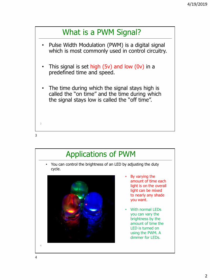
• You can control the brightness of an LED by adjusting the duty cycle.
• By varying the amount of time each light is on the overall light can be mixed to nearly any shade you want.
• With normal LEDs you can vary the brightness by the amount of time the LED is turned on using the PWM. A dimmer for LEDs.
3
4
4/19/2019
3
Applications of PWM
5
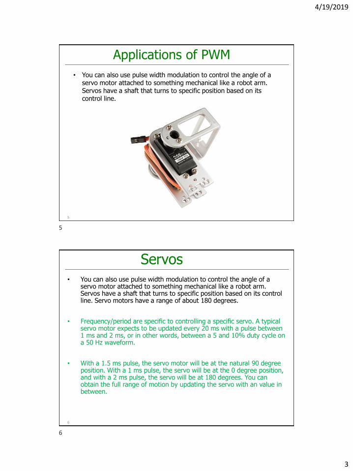
• You can also use pulse width modulation to control the angle of a servo motor attached to something mechanical like a robot arm. Servos have a shaft that turns to specific position based on its control line.
Servos• You can also use pulse width modulation to control the angle of a
servo motor attached to something mechanical like a robot arm. Servos have a shaft that turns to specific position based on its control line. Servo motors have a range of about 180 degrees.
• Frequency/period are specific to controlling a specific servo. A typical servo motor expects to be updated every 20 ms with a pulse between 1 ms and 2 ms, or in other words, between a 5 and 10% duty cycle on a 50 Hz waveform.
• With a 1.5 ms pulse, the servo motor will be at the natural 90 degree position. With a 1 ms pulse, the servo will be at the 0 degree position, and with a 2 ms pulse, the servo will be at 180 degrees. You can obtain the full range of motion by updating the servo with an value in between.
6
5
6
4/19/2019
4
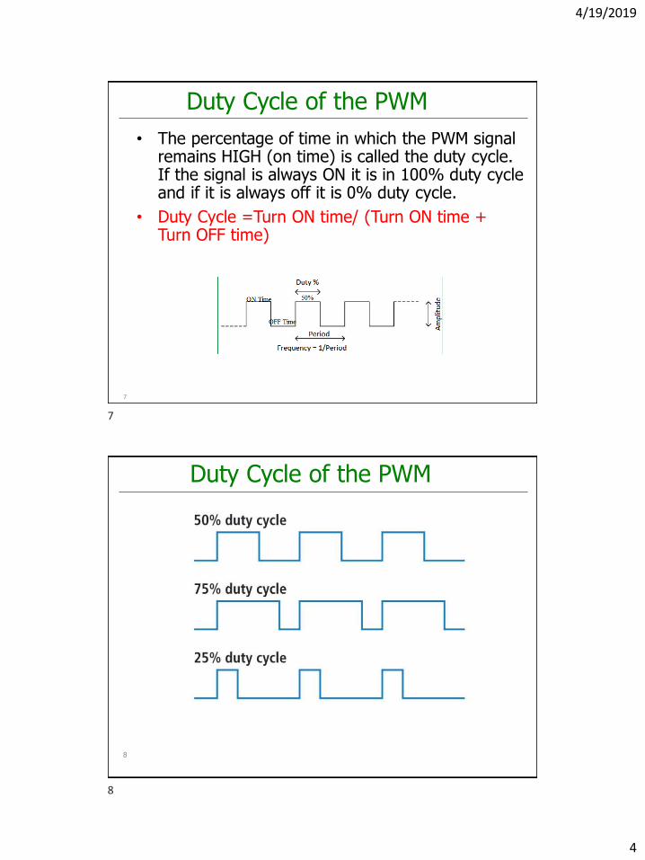
Duty Cycle of the PWM
• The percentage of time in which the PWM signal remains HIGH (on time) is called the duty cycle. If the signal is always ON it is in 100% duty cycle and if it is always off it is 0% duty cycle.
• Duty Cycle =Turn ON time/ (Turn ON time + Turn OFF time)
7
Duty Cycle of the PWM
8
7
8
4/19/2019
5
Frequency of a PWM Signal
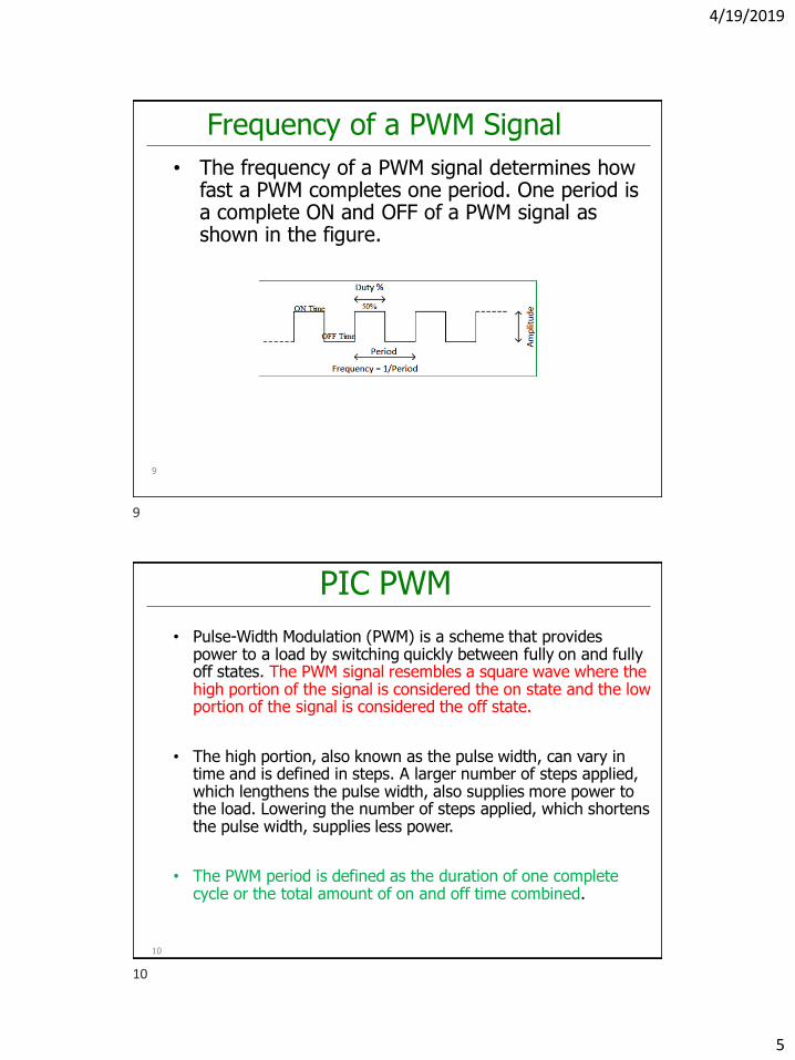
• The frequency of a PWM signal determines how fast a PWM completes one period. One period is a complete ON and OFF of a PWM signal as shown in the figure.
9
PIC PWM
• Pulse-Width Modulation (PWM) is a scheme that provides power to a load by switching quickly between fully on and fully off states. The PWM signal resembles a square wave where the high portion of the signal is considered the on state and the low portion of the signal is considered the off state.
• The high portion, also known as the pulse width, can vary in time and is defined in steps. A larger number of steps applied, which lengthens the pulse width, also supplies more power to the load. Lowering the number of steps applied, which shortens the pulse width, supplies less power.
• The PWM period is defined as the duration of one complete cycle or the total amount of on and off time combined.
10
9
10
4/19/2019
6
PIC PWM
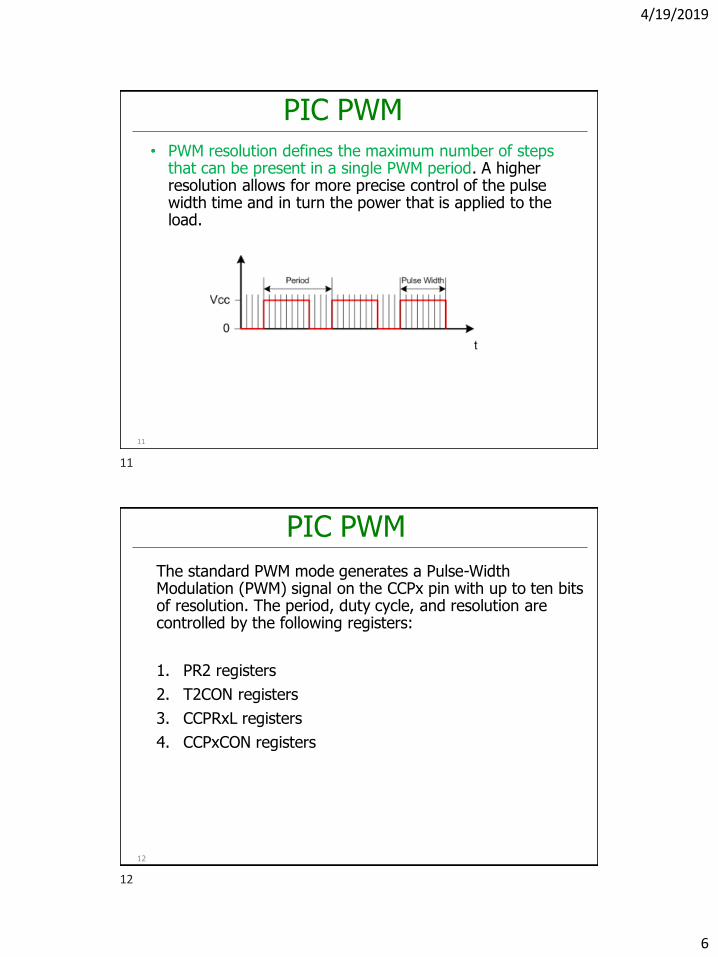
• PWM resolution defines the maximum number of steps that can be present in a single PWM period. A higher resolution allows for more precise control of the pulse width time and in turn the power that is applied to the load.
11
PIC PWM
The standard PWM mode generates a Pulse-Width Modulation (PWM) signal on the CCPx pin with up to ten bits of resolution. The period, duty cycle, and resolution are controlled by the following registers:
1. PR2 registers
2. T2CON registers
3. CCPRxL registers
4. CCPxCON registers
12
11
12
4/19/2019
7
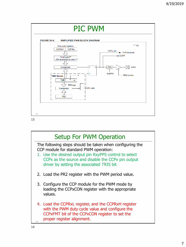
PIC PWM
13
Setup For PWM Operation
14
The following steps should be taken when configuring the CCP module for standard PWM operation:1. Use the desired output pin RxyPPS control to select
CCPx as the source and disable the CCPx pin output driver by setting the associated TRIS bit.
2. Load the PR2 register with the PWM period value.
3. Configure the CCP module for the PWM mode by loading the CCPxCON register with the appropriate values.
4. Load the CCPRxL register, and the CCPRxH register with the PWM duty cycle value and configure the CCPxFMT bit of the CCPxCON register to set the proper register alignment.
13
14
4/19/2019
8
Setup For PWM Operation
15
5. Configure and start Timer2:• Clear the TMR2IF interrupt flag bit of the PIR4
register. • Configure the T2CKPS bits of the T2CON register
with the Timer prescale value.• Enable the Timer by setting the TMR2ON bit of the
T2CON register.
6. Enable PWM output pin:• Wait until the Timer overflows and the TMR2IF bit
of the PIR4 register is set.• Enable the CCPx pin output driver by clearing the
associated TRIS bit.
CCP/PWM Clock Selection
• The PIC16F18855/75 allows each individual CCP and PWM module to select the timer source that controls the module. Each module has an independent selection.
• As there are up to three 8-bit timers with auto-reload (Timer2/4/6), PWM mode on the CCP and PWM modules can use any of these timers. The CCPTMRS0 and CCPTMRS1 registers is used to select which timer is used.
16
15
16
4/19/2019
9
PWM Period
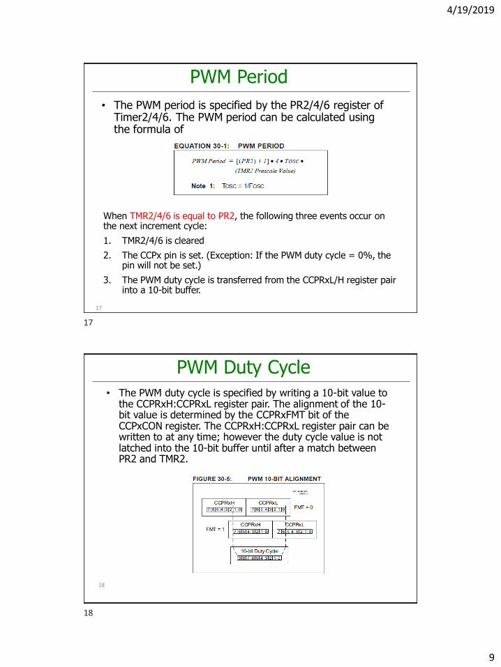
• The PWM period is specified by the PR2/4/6 register of Timer2/4/6. The PWM period can be calculated using the formula of
17
When TMR2/4/6 is equal to PR2, the following three events occur on the next increment cycle:
1. TMR2/4/6 is cleared
2. The CCPx pin is set. (Exception: If the PWM duty cycle = 0%, the pin will not be set.)
3. The PWM duty cycle is transferred from the CCPRxL/H register pair into a 10-bit buffer.
PWM Duty Cycle
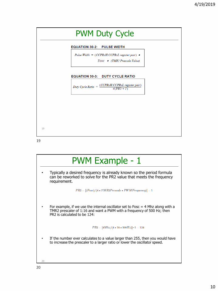
• The PWM duty cycle is specified by writing a 10-bit value to the CCPRxH:CCPRxL register pair. The alignment of the 10-bit value is determined by the CCPRxFMT bit of the CCPxCON register. The CCPRxH:CCPRxL register pair can be written to at any time; however the duty cycle value is not latched into the 10-bit buffer until after a match between PR2 and TMR2.
18
17
18
4/19/2019
10
PWM Duty Cycle
19
PWM Example - 1• Typically a desired frequency is already known so the period formula
can be reworked to solve for the PR2 value that meets the frequency requirement.
• For example, if we use the internal oscillator set to Fosc = 4 Mhz along with a TMR2 prescaler of 1:16 and want a PWM with a frequency of 500 Hz; then PR2 is calculated to be 124:
• If the number ever calculates to a value larger than 255, then you would have to increase the prescaler to a larger ratio or lower the oscillator speed.
20
19
20
4/19/2019
11
PWM Example - 1• The Duty Cycle desired is also typically a known value, so once the frequency
is set via the PR2 value then the pulse width calculation can be reworked to solve for the CCPRxH:CCPRxL value with the formula below:
• Since PR2 was already calculated as 124, and assuming a 50% duty cycle, then the answer below is calculated:
• 250 in binary is 0011111010 which gets broken up between the two registers to:
21
CCPRxH:CCPRxL
CCPRxH:CCPRxL
CCPRxH CCPRxL
PWM Duty Cycle
22
• CCPRxH:CCPRxL register pair are used to double buffer the PWM duty cycle. This double buffering is essential for glitchless PWM operation.
• The 8-bit timer TMR2 register is concatenated with either the 2-bit internal system clock (FOSC), or two bits of the prescaler, to create the 10-bit time base. The system clock is used if the Timer2 prescaler is set to 1:1.
• When the 10-bit time base matches the CCPRxH:CCPRxLregister pair, then the CCPx pin is cleared.
21
22
4/19/2019
12
PWM Resolution
23
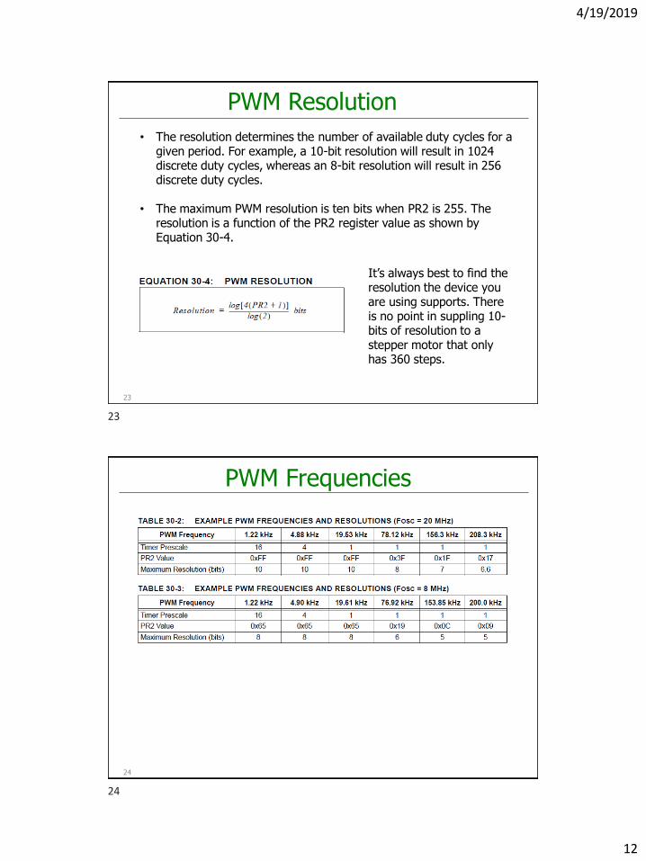
• The resolution determines the number of available duty cycles for a given period. For example, a 10-bit resolution will result in 1024 discrete duty cycles, whereas an 8-bit resolution will result in 256 discrete duty cycles.
• The maximum PWM resolution is ten bits when PR2 is 255. The resolution is a function of the PR2 register value as shown by Equation 30-4.
It’s always best to find the resolution the device you are using supports. There is no point in suppling 10-bits of resolution to a stepper motor that only has 360 steps.
PWM Frequencies
24
23
24
4/19/2019
13
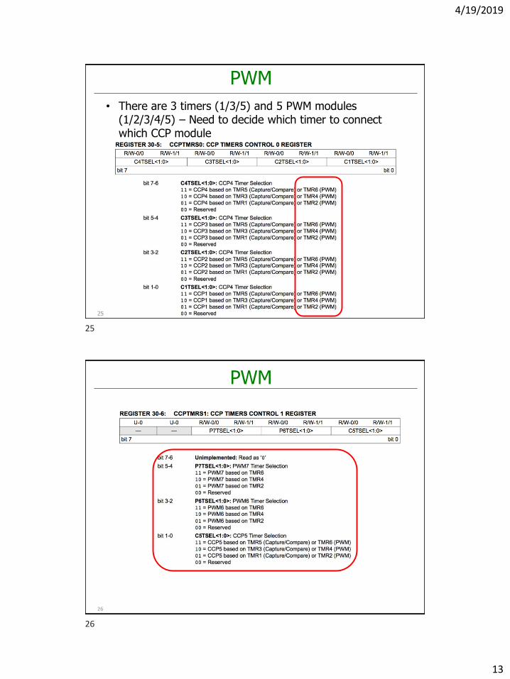
PWM
25
• There are 3 timers (1/3/5) and 5 PWM modules (1/2/3/4/5) – Need to decide which timer to connect which CCP module
PWM
26
25
26
4/19/2019
14
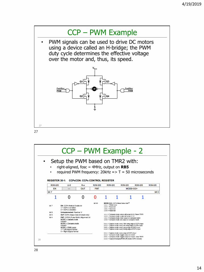
CCP – PWM Example• PWM signals can be used to drive DC motors
using a device called an H-bridge; the PWM duty cycle determines the effective voltage over the motor and, thus, its speed.
27
CCP – PWM Example - 2
• Setup the PWM based on TMR2 with:• right-aligned, fosc = 4MHz, output on RB5
• required PWM frequency: 20kHz => T = 50 microseconds
28
1 0 0 0 1 1 1 1
27
28
4/19/2019
15
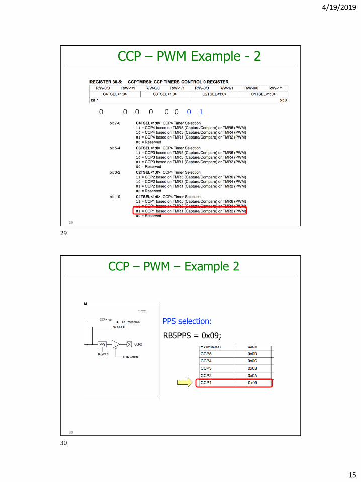
CCP – PWM Example - 2
29
0 0 0 0 0 0 0 1
CCP – PWM – Example 2
30
RB5PPS = 0x09;
PPS selection:
29
30
4/19/2019
16
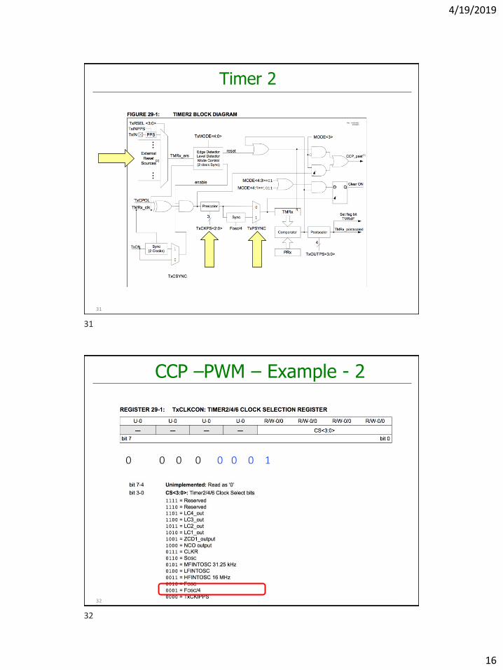
Timer 2
31
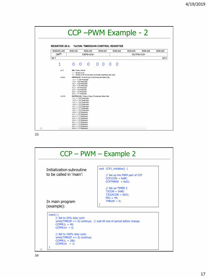
CCP –PWM – Example - 2
32
0 0 0 0 0 0 0 1
31
32
4/19/2019
17
CCP –PWM Example - 2
33
1 0 0 0 0 0 0 0
34
CCP – PWM – Example 2
void CCP1_initialize() {
// Set up the PWM part of CCPCCP1CON = 0x8F;CCPTMRS0 = 0x01;
// Set up TIMER 2T2CON = 0x80;T2CLKCON = 0x01;PR2 = 49;TMR2IF = 0;
}
Initialization subroutine to be called in ‘main’:
In main program (example):
main() {// Set to 20% duty cyclewhile(TMR2IF == 0) continue; // wait till end of period before changeCCPPR1L = 40; CCPPR1H = 0;
// Set to 100% duty cyclewhile(TMR2IF == 0) continue;CCPPR1L = 200;CCPPR1H = 0;
}
33
34
Related Documents


