TAI-TECH www.tai-tech.com.tw P2 1. Features 2. Applications 3. Dimensions 1.10/100 Base-T, Single Port, Low profile Modules w/Surge Protection (LAN-128740M162P7A8(16 Pin) 、 LAN-128740M162P7B8 (16 Pin) 、 LAN-128740M165P7A8 (16 Pin) 、 LAN-5008M(24 Pin) 2.1000 Base-T, Single Port, Low profile Modules w/Surge Protection (LAN-131850G241P1A8(24 Pin)、LAN-131850G242P1A8 (24 Pin)、LAN-161040G241P1A8 (24 Pin)、 LAN-161040G241P1B8 (24 Pin)、LAN-161040G242P1A8 (24 Pin)、LAN-171445G241P7B8 (24 Pin)、 LAN-281450G481P1A8 (48 Pin)、LAN-321050G502P1A8 (50 Pin) ) 3. Notebook pc LAN Pulse Transformer Module 4. Hub switch, Ap router Multi-port Pulse Transformer. Pulse Transformer Module LAN-SERIES 1. Low profile, small footprint saves board space and height 2. Compliant with IEEE 802.3ab standard for 10/100、1000BASE-T 3. Pin to Pin compatibility with LAN transformer 4. Operating temperature range: 0°C to +70°C (10/100), 0°C to +85°C(1G) 5. Storage temperature range: 0°C to +85°C 6. 100% Lead (Pb)-Free and RoHS compliant. Pb-free Pb Halogen-free Halogen LAN-128740M162P7A8 A(mm) A’(mm) B(mm) B’(mm) C(mm) C’(mm) D(mm) E(mm) F(mm) 12.7±0.25 8.89±0.25 8.67±0.25 7.2±0.25 4.0±0.25 0.8±0.05 0.6±0.1 1.27±0.25 1.00±0.25 Tolerance: XX.X0 +/-0.25(mm) 0.XX +/-0.05(mm) Units: mm(inch)Tolerance: XX.X0 +/-0.25(0.010) 0.XX +/-0.05(0.002)

Welcome message from author
This document is posted to help you gain knowledge. Please leave a comment to let me know what you think about it! Share it to your friends and learn new things together.
Transcript

TAI-TECH
www.tai-tech.com.tw
P2
1. Features
2. Applications
3. Dimensions
1.10/100 Base-T, Single Port, Low profile Modules w/Surge Protection
(LAN-128740M162P7A8(16 Pin)、LAN-128740M162P7B8 (16 Pin)、LAN-128740M165P7A8 (16 Pin)、LAN-5008M(24 Pin)
2.1000 Base-T, Single Port, Low profile Modules w/Surge Protection
(LAN-131850G241P1A8(24 Pin)、LAN-131850G242P1A8 (24 Pin)、LAN-161040G241P1A8 (24 Pin)、
LAN-161040G241P1B8 (24 Pin)、LAN-161040G242P1A8 (24 Pin)、LAN-171445G241P7B8 (24 Pin)、
LAN-281450G481P1A8 (48 Pin)、LAN-321050G502P1A8 (50 Pin) )
3. Notebook pc LAN Pulse Transformer Module
4. Hub switch, Ap router Multi-port Pulse Transformer.
Pulse Transformer Module LAN-SERIES
1. Low profile, small footprint saves board space and height 2. Compliant with IEEE 802.3ab standard for 10/100、1000BASE-T 3. Pin to Pin compatibility with LAN transformer 4. Operating temperature range: 0°C to +70°C (10/100), 0°C to +85°C(1G) 5. Storage temperature range: 0°C to +85°C 6. 100% Lead (Pb)-Free and RoHS compliant.
Pb-free
PbHalogen-free
Halogen
LAN-128740M162P7A8A(mm) A’(mm) B(mm) B’(mm) C(mm) C’(mm) D(mm) E(mm) F(mm)
12.7±0.25 8.89±0.25 8.67±0.25 7.2±0.25 4.0±0.25 0.8±0.05 0.6±0.1 1.27±0.25 1.00±0.25
Tolerance: XX.X0 +/-0.25(mm)
0.XX +/-0.05(mm)
Units: mm(inch)Tolerance: XX.X0 +/-0.25(0.010)
0.XX +/-0.05(0.002)

TAI-TECH
www.tai-tech.com.tw
P3
Tolerance: XX.X0 +/-0.25(mm)
0.XX +/-0.05(mm)
LAN128740M162P7B8
A(mm) A’(mm) B(mm) B’(mm) C(mm) C’(mm) D(mm) E(mm) F(mm)
12.7±0.25 8.89±0.25 8.67±0.25 7.2±0.25 4.0±0.25 0.8±0.05 0.6±0.1 1.27±0.25 1.00±0.25
LAN-128740M165P7A8A(mm) A’(mm) B(mm) B’(mm) C(mm) C’(mm) D(mm) E(mm) F(mm)
12.7±0.25 8.89±0.25 8.67±0.25 7.2±0.25 4.0±0.25 0.8±0.05 0.6±0.1 1.27±0.25 1.00±0.25
Tolerance: XX.X0 +/-0.25(mm)
0.XX +/-0.05(mm)
Units: mm(inch)Tolerance: XX.X0 +/-0.25(0.010)
0.XX +/-0.05(0.002)
Units: mm(inch)Tolerance: XX.X0 +/-0.25(0.010)
0.XX +/-0.05(0.002)
LAN-5008M
A(mm) A’(mm) B(mm) B’(mm) C(mm) C’(mm) D(mm) E(mm) F(mm) G(mm) H(mm)
15.1 14.6 9.4 8.9 4.1 0.8 6.1 4.1 3.1 0.8 1.0
I(mm) J(mm) K(mm) L(mm) M(mm) N(mm) O(mm) P(mm)
2.1 0.7 0.3 1.1 0.8 0.7 0.3 4.7
Units: mm(inch)Tolerance: XX.X0 +/-0.25(0.010)
0.XX +/-0.05(0.002)
Tolerance: XX.X0 +/-0.25(mm)
0.XX +/-0.05(mm)
TAI-TECH
www.tai-tech.com.tw
P4
LAN-131850G242P1A8
A(mm) A’(mm) B(mm) B’(mm) C(mm) C’(mm) D(mm) E(mm) F(mm) G(mm) H(mm)
13.60 13.1 18.15 17.35 5.0 max 1.2 5.315 3.335 2.345 0.6 0.99
J(mm) K(mm) L(mm)
0.8 0.3 1.2
LAN-131850G241P1A8
A(mm) A’(mm) B(mm) B’(mm) C(mm) C’(mm) D(mm) E(mm) F(mm) G(mm) H(mm)
13.60 13.1 18.15 17.35 5.0 max 1.2 5.315 3.335 2.345 0.6 0.99
J(mm) K(mm) L(mm)
0.8 0.3 1.2
Tolerance: XX.X0 +/-0.25(mm)
0.XX +/-0.05(mm)
Tolerance: XX.X0 +/-0.25(mm)
0.XX +/-0.05(mm)
Tolerance: XX.X0 +/-0.25(mm)
0.XX +/-0.05(mm)
Tolerance: XX.X0 +/-0.25(mm)
0.XX +/-0.05(mm)
LAN-161040G241P1A8
A(mm) A’(mm) B(mm) B’(mm) C(mm) C’(mm) D(mm) E(mm) F(mm) G(mm) H(mm)
16.5 16.0 10.3 9.65 4.1 0.8 6.75 4.75 3.75 0.4 1.0
I(mm) J(mm) K(mm) L(mm)
2.75 0.65 0.2 1.0
Units: mm(inch)Tolerance: XX.X0 +/-0.25(0.010)
0.XX +/-0.05(0.002)
Units: mm(inch)Tolerance: XX.X0 +/-0.25(0.010)
0.XX +/-0.05(0.002)
TAI-TECH
www.tai-tech.com.tw
P5
Tolerance: XX.X0 +/-0.25(mm)
0.XX +/-0.05(mm)
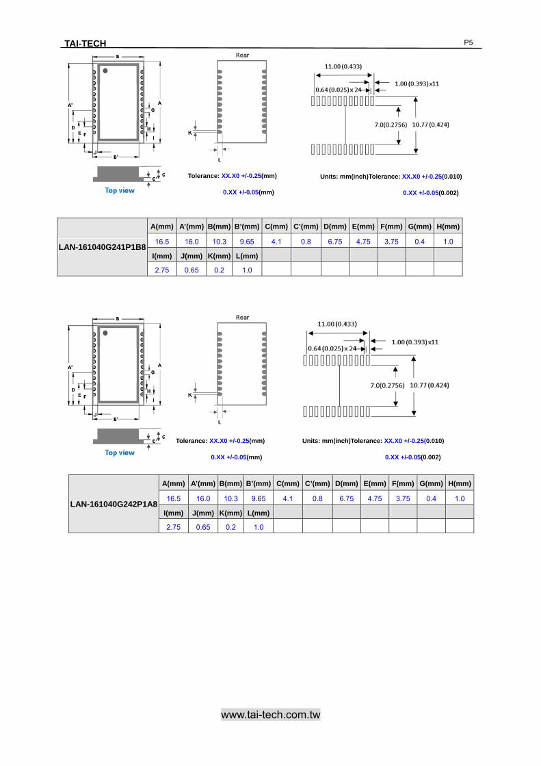
LAN-161040G241P1B8
A(mm) A’(mm) B(mm) B’(mm) C(mm) C’(mm) D(mm) E(mm) F(mm) G(mm) H(mm)
16.5 16.0 10.3 9.65 4.1 0.8 6.75 4.75 3.75 0.4 1.0
I(mm) J(mm) K(mm) L(mm)
2.75 0.65 0.2 1.0
Tolerance: XX.X0 +/-0.25(mm)
0.XX +/-0.05(mm)
LAN-161040G242P1A8
A(mm) A’(mm) B(mm) B’(mm) C(mm) C’(mm) D(mm) E(mm) F(mm) G(mm) H(mm)
16.5 16.0 10.3 9.65 4.1 0.8 6.75 4.75 3.75 0.4 1.0
I(mm) J(mm) K(mm) L(mm)
2.75 0.65 0.2 1.0
Units: mm(inch)Tolerance: XX.X0 +/-0.25(0.010)
0.XX +/-0.05(0.002)
Units: mm(inch)Tolerance: XX.X0 +/-0.25(0.010)
0.XX +/-0.05(0.002)
TAI-TECH
www.tai-tech.com.tw
P6
Tolerance: XX.X0 +/-0.25(mm)
0.XX +/-0.05(mm)
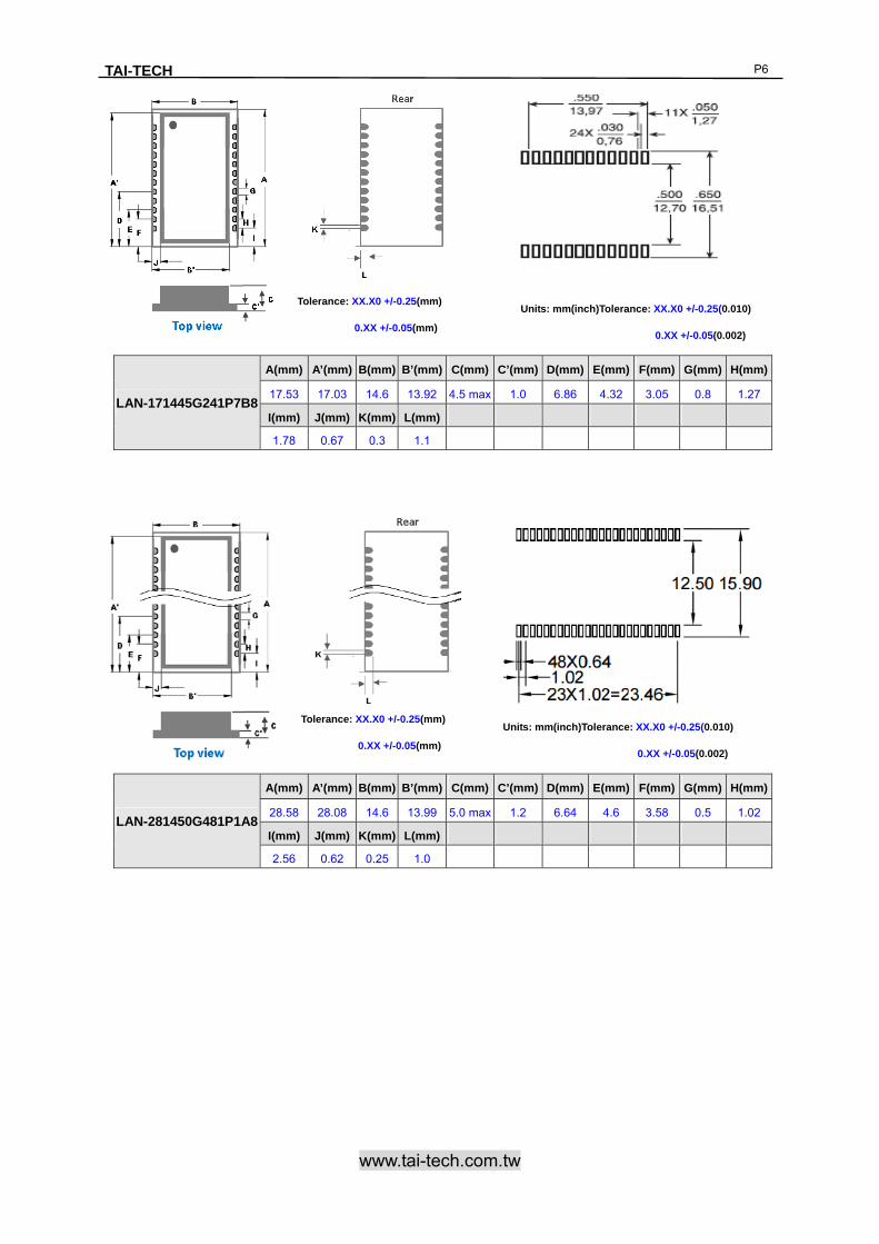
LAN-171445G241P7B8
A(mm) A’(mm) B(mm) B’(mm) C(mm) C’(mm) D(mm) E(mm) F(mm) G(mm) H(mm)
17.53 17.03 14.6 13.92 4.5 max 1.0 6.86 4.32 3.05 0.8 1.27
I(mm) J(mm) K(mm) L(mm)
1.78 0.67 0.3 1.1
Tolerance: XX.X0 +/-0.25(mm)
0.XX +/-0.05(mm)
LAN-281450G481P1A8
A(mm) A’(mm) B(mm) B’(mm) C(mm) C’(mm) D(mm) E(mm) F(mm) G(mm) H(mm)
28.58 28.08 14.6 13.99 5.0 max 1.2 6.64 4.6 3.58 0.5 1.02
I(mm) J(mm) K(mm) L(mm)
2.56 0.62 0.25 1.0
Units: mm(inch)Tolerance: XX.X0 +/-0.25(0.010)
0.XX +/-0.05(0.002)
Units: mm(inch)Tolerance: XX.X0 +/-0.25(0.010)
0.XX +/-0.05(0.002)
TAI-TECH
www.tai-tech.com.tw
P7
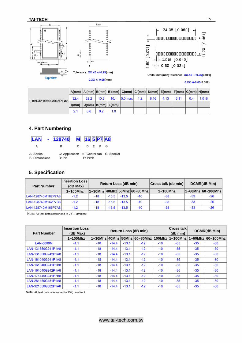
4. Part Numbering
5. Specification
LAN-321050G502P1A8
A(mm) A’(mm) B(mm) B’(mm) C(mm) C’(mm) D(mm) E(mm) F(mm) G(mm) H(mm)
32.4 32.2 10.3 10.1 5.0 max 1.2 6.16 4.13 3.11 0.4 1.016
I(mm) J(mm) K(mm) L(mm)
2.1 0.6 0.2 1.0
Tolerance: XX.X0 +/-0.25(mm)
0.XX +/-0.05(mm)
Units: mm(inch)Tolerance: XX.X0 +/-0.25(0.010)
0.XX +/-0.05(0.002)
Part Number Insertion Loss
(dB Max) Return Loss (dB min) Cross talk (db min) DCMR(dB Min)
1~100Mhz 1~30Mhz 40Mhz 50Mhz 60~80Mhz 1~100Mhz 1~60Mhz 60~100MhzLAN-128740M162P7A8 -1.2 -18 -15.5 -13.5 -10 -38 -33 -26
LAN-128740M162P7B8 -1.2 -18 -15.5 -13.5 -10 -38 -33 -26
LAN-128740M165P7A8 -1.2 -18 -15.5 -13.5 -10 -38 -33 -26
Note: All test data referenced to 25℃ ambient
Part Number Insertion Loss
(dB Max) Return Loss (dB min)
Cross talk (db min)
DCMR(dB Min)
1~100Mhz 1~30Mhz 40Mhz 50Mhz 60~80Mhz 100Mhz 1~100Mhz 1~60Mhz 60~100MhzLAN-5008M -1.1 -18 -14.4 -13.1 -12 -10 -35 -35 -30
LAN-131850G241P1A8 -1.1 -18 -14.4 -13.1 -12 -10 -35 -35 -30
LAN-131850G242P1A8 -1.1 -18 -14.4 -13.1 -12 -10 -35 -35 -30
LAN-161040G241P1A8 -1.1 -18 -14.4 -13.1 -12 -10 -35 -35 -30
LAN-161040G241P1B8 -1.1 -18 -14.4 -13.1 -12 -10 -35 -35 -30
LAN-161040G242P1A8 -1.1 -18 -14.4 -13.1 -12 -10 -35 -35 -30
LAN-171445G241P7B8 -1.1 -18 -14.4 -13.1 -12 -10 -35 -35 -30
LAN-281450G481P1A8 -1.1 -18 -14.4 -13.1 -12 -10 -35 -35 -30
LAN-321050G502P1A8 -1.1 -18 -14.4 -13.1 -12 -10 -35 -35 -30
Note: All test data referenced to 25℃ ambient
LAN - 128740 M 16 5 P7 A8 A B C D E F G
A: Series C: Application E: Center tab G: Special B: Dimensions D: Pin F: Pitch
TAI-TECH
www.tai-tech.com.tw
P8
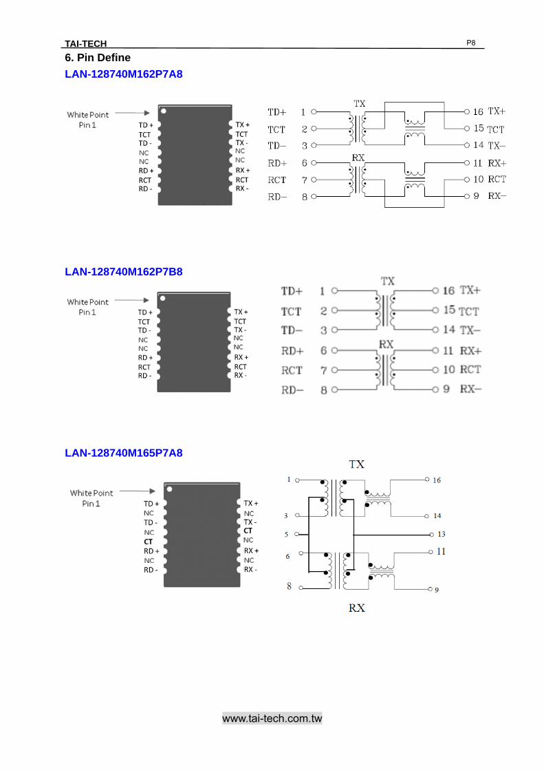
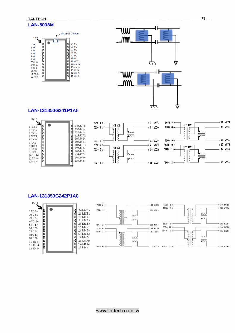
6. Pin Define
LAN-128740M162P7A8
LAN-128740M162P7B8
LAN-128740M165P7A8
TAI-TECH
www.tai-tech.com.tw
P9
LAN-5008M
LAN-131850G241P1A8
LAN-131850G242P1A8

TAI-TECH
www.tai-tech.com.tw
P1
LAN-161040G241P1A8
LAN-161040G241P1B8
LAN-161040G242P1A8
LAN-171445G241P7B8

TAI-TECH
www.tai-tech.com.tw
P1
LAN-281450G481P1A8
LAN-321050G502P1A8
TAI-TECH
www.tai-tech.com.tw
P1
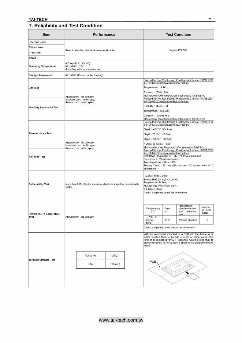
7. Reliability and Test Condition
Item Performance Test Condition
Insertion Loss
Refer to standard electrical characteristics list. Agilent E5071C Retuen Loss
Cross talk
DCMR
Operating Temperature 0°C to +70°C (10/100) 0℃~+85℃ (1G) (Including self - temperature rise)
Storage Temperature 0℃~+85℃(Product without taping)
Life Test
Appearance:No damage. Insertion Loss:within spec. Return Loss:within spec.
Preconditioning: Run through IR reflow for 2 times.( IPC/JEDEC J-STD-020DClassification Reflow Profiles
Temperature: 85±2℃
Duration:1000±12hrs Measured at room temperature after placing for 24±2 hrs
Humidity Resistance Test
Preconditioning: Run through IR reflow for 2 times.( IPC/JEDEC J-STD-020DClassification Reflow Profiles
Humidity:85±2﹪R.H,
Temperature:85℃±2℃
Duration:1000hrs Min. Measured at room temperature after placing for 24±2 hrs
Thermal shock Test
Appearance:No damage. Insertion Loss:within spec. Return Loss:within spec.
Preconditioning: Run through IR reflow for 2 times.( IPC/JEDEC J-STD-020DClassification Reflow Profiles
Step1:-40±2℃ 30±5min
Step2:25±2℃ ≦0.5min
Step3:105±2℃ 30±5min
Number of cycles: 500 Measured at room fempraturc after placing for 24±2 hrs
Vibration Test
Preconditioning: Run through IR reflow for 2 times.( IPC/JEDEC J-STD-020DClassification Reflow Profiles Oscillation Frequency: 10~2K~10Hz for 20 minutes Equipment: Vibration checker Total Amplitude:1.52mm±10% Testing Time : 12 hours(20 minutes, 12 cycles each of 3 orientations)。
Solderability Test
More than 95% of bottom terminal electrode should be covered with solder.
Preheat: 150℃,60sec.。
Solder:Sn96.5% Ag3% Cu0.5% Temperature: 245±5℃。 Flux for lead free: Rosin. 9.5%。 Dip time: 4±1sec。
Depth: completely cover the termination
Resistance To Solder Heat Test
Appearance:No damage.
Depth: completely cover bottom the termination
Temperature(°C)
Time (s)
Temperature ramp/immersion and emersion rate
Number of heat cycles
260 ±5 (solder temp)
10 ±1 25mm/s ±6 mm/s 1
Terminal Strength Test
Series No. 2(Kg)
LAN 1.0(min.)
With the component mounted on a PCB with the device to be tested, apply a force to the side of a device being tested. This force shall be applied for 60 +1 seconds. Also the force shall be applied gradually as not to apply a shock to the component being tested.
TAI-TECH
www.tai-tech.com.tw
P1
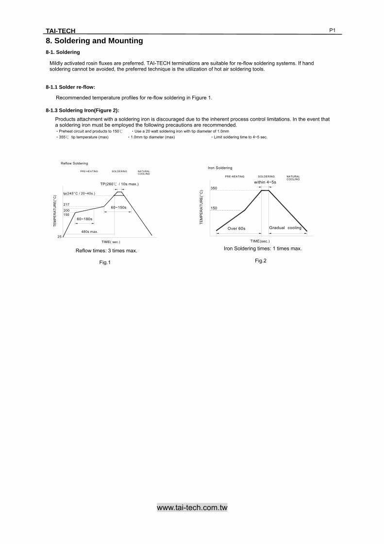
8. Soldering and Mounting 8-1. Soldering
8-1.1 Solder re-flow:
8-1.3 Soldering Iron(Figure 2):
Recommended temperature profiles for re-flow soldering in Figure 1.
Mildly activated rosin fluxes are preferred. TAI-TECH terminations are suitable for re-flow soldering systems. If hand soldering cannot be avoided, the preferred technique is the utilization of hot air soldering tools.
Products attachment with a soldering iron is discouraged due to the inherent process control limitations. In the event that a soldering iron must be employed the following precautions are recommended. ‧Preheat circuit and products to 150℃ ‧Use a 20 watt soldering iron with tip diameter of 1.0mm
‧355℃ tip temperature (max) ‧1.0mm tip diameter (max) ‧Limit soldering time to 4~5 sec.
Fig.2
SOLDERINGCOOLINGNATURALPRE-HEATING
TE
MP
ER
AT
UR
E(°
C)
within 4~5s
Gradual cooling
350
150
TIME(sec.)
Iron Soldering
Over 60s
Iron Soldering times: 1 times max. Reflow times: 3 times max.
Fig.1
TE
MP
ER
AT
UR
E(°
C)
60~180s
60~150s217
150
TIME( sec.)
200
25
480s max.
tp(245°C / 20~40s.)
PRE-HEATING
Reflow Soldering
SOLDERING NATURALCOOLING
TP(260℃ / 10s max.)
TAI-TECH
www.tai-tech.com.tw
P1
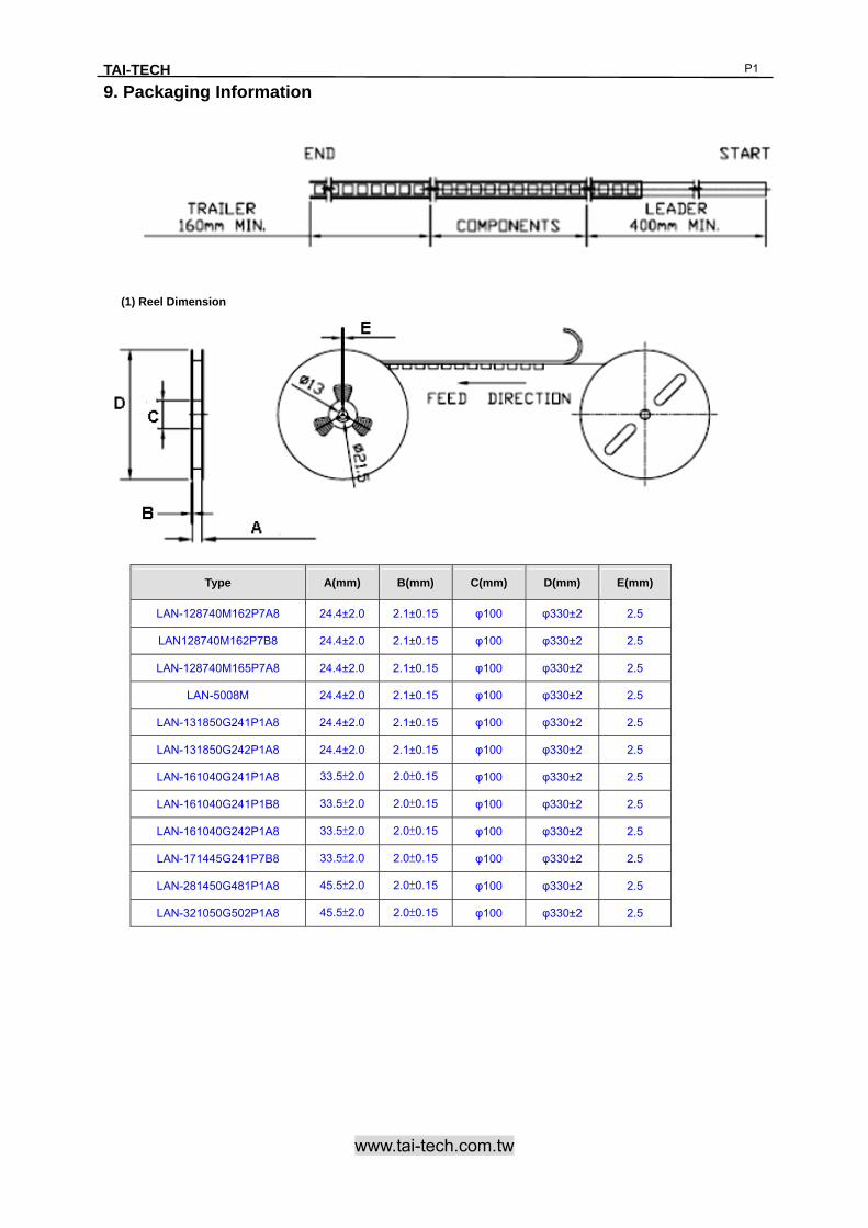
9. Packaging Information
(1) Reel Dimension
Type A(mm) B(mm) C(mm) D(mm) E(mm)
LAN-128740M162P7A8 24.4±2.0 2.1±0.15 φ100 φ330±2 2.5
LAN128740M162P7B8 24.4±2.0 2.1±0.15 φ100 φ330±2 2.5
LAN-128740M165P7A8 24.4±2.0 2.1±0.15 φ100 φ330±2 2.5
LAN-5008M 24.4±2.0 2.1±0.15 φ100 φ330±2 2.5
LAN-131850G241P1A8 24.4±2.0 2.1±0.15 φ100 φ330±2 2.5
LAN-131850G242P1A8 24.4±2.0 2.1±0.15 φ100 φ330±2 2.5
LAN-161040G241P1A8 33.5±2.0 2.0±0.15 φ100 φ330±2 2.5
LAN-161040G241P1B8 33.5±2.0 2.0±0.15 φ100 φ330±2 2.5
LAN-161040G242P1A8 33.5±2.0 2.0±0.15 φ100 φ330±2 2.5
LAN-171445G241P7B8 33.5±2.0 2.0±0.15 φ100 φ330±2 2.5
LAN-281450G481P1A8 45.5±2.0 2.0±0.15 φ100 φ330±2 2.5
LAN-321050G502P1A8 45.5±2.0 2.0±0.15 φ100 φ330±2 2.5

TAI-TECH
www.tai-tech.com.tw
P1
(2) Tape Dimension
(3) Packaging Quantity
LAN-128740M162P7A8 LAN128740M162P7B8 LAN-128740M165P7A8 LAN-5008M
Chip / Reel 900 900 900 800
LAN-131850G241P1A8 LAN-131850G242P1A8 LAN-161040G241P1A8 LAN-161040G241P1B8
Chip / Reel 400 400 800 800
LAN-161040G242P1A8 LAN-171445G241P7B8 LAN-281450G481P1A8 LAN-321050G502P1A8
Chip / Reel 800 500 500 600
Series Bo(mm) Ao(mm) Ko(mm) P(mm) Po(mm) P2(mm) W(mm) F(mm) D(mm)
LAN-128740M162P7A8 13.0±0.1 9.0±0.1 4.4±0.1 16.00±0.1 4.0±0.1 2.0±0.1 24±0.3 11.5±0.1 1.5±0.1
LAN128740M162P7B8 13.0±0.1 9.0±0.1 4.4±0.1 16.00±0.1 4.0±0.1 2.0±0.1 24±0.3 11.5±0.1 1.5±0.1
LAN-128740M165P7A8 13.0±0.1 9.0±0.1 4.4±0.1 16.00±0.1 4.0±0.1 2.0±0.1 24±0.3 11.5±0.1 1.5±0.1
LAN-5008M 15.50±0.1 9.65±0.1 4.80±0.1 16.00±0.1 4.0±0.1 2.0±0.1 24±0.3 11.5±0.1 1.5±0.1
LAN-131850G241P1A8 13.90±0.1 18.45±0.1 5.6±0.1 24.00±0.1 4.0±0.1 2.0±0.1 24±0.3 11.5±0.1 1.5±0.1
LAN-131850G242P1A8 13.90±0.1 18.45±0.1 5.6±0.1 24.00±0.1 4.0±0.1 2.0±0.1 24±0.3 11.5±0.1 1.5±0.1
LAN-161040G241P1A8 16.80±0.1 10.6±0.1 4.90±0.1 16.00±0.1 4.0±0.1 2.0±0.1 32±0.3 14.2±0.1 1.5±0.1
LAN-161040G241P1B8 16.80±0.1 10.6±0.1 4.90±0.1 16.00±0.1 4.0±0.1 2.0±0.1 32±0.3 14.2±0.1 1.5±0.1
LAN-161040G242P1A8 16.80±0.1 10.6±0.1 4.90±0.1 16.00±0.1 4.0±0.1 2.0±0.1 32±0.3 14.2±0.1 1.5±0.1
LAN-171445G241P7B8 17.93±0.1 15.3±0.1 4.80±0.1 23.45±0.1 4.0±0.1 2.0±0.1 26±0.3 12.75±0.1 1.5±0.1
LAN-281450G481P1A8 28.90±0.1 14.9±0.1 5.80±0.1 20.00±0.1 4.0±0.1 2.0±0.15 44.0±0.3 20.2±0.15 1.5±0.1
LAN-321050G502P1A8 32.70±0.1 10.60±0.1 5.80±0.1 16.00±0.1 4.0±0.1 2.0±0.15 44.0±0.3 20.2±0.15 1.5±0.1
TAI-TECH
www.tai-tech.com.tw
P1
Application Notice
‧Storage Conditions(component level) To maintain the solderability of terminal electrodes: 1. TAI-TECH products meet IPC/JEDEC J-STD-020D standard-MSL, level 1. 2. Temperature and humidity conditions: Less than 40℃ and 60% RH. 3. Recommended products should be used within 12 months form the time of delivery. 4. The packaging material should be kept where no chlorine or sulfur exists in the air.
‧Transportation 1. Products should be handled with care to avoid damage or contamination from perspiration
and skin oils. 2. The use of tweezers or vacuum pick up is strongly recommended for individual components.3. Bulk handling should ensure that abrasion and mechanical shock are minimized.
Related Documents