PULSE TOOLS INSTRUCTION MANUAL & MAINTENANCE R Rev 5.0 (06/22/2015) READ ALL THE INSTRUCTIONS COMPLETELY BEFORE OPERATION. COMPLY WITH ALL THE INSTRUCTIONS AND RULES IN THIS MANUAL AND SAVE THIS MANUAL FOR FUTURE REFERENCE. 1

Welcome message from author
This document is posted to help you gain knowledge. Please leave a comment to let me know what you think about it! Share it to your friends and learn new things together.
Transcript

PULSE TOOLS INSTRUCTION MANUAL & MAINTENANCE
R
Rev 5.0 (06/22/2015)
READ ALL THE INSTRUCTIONS COMPLETELY BEFORE OPERATION.
COMPLY WITH ALL THE INSTRUCTIONS AND RULES IN THIS MANUAL AND SAVE THIS MANUAL FOR
FUTURE REFERENCE.
1

www.mountztorque.com
TABLE OF CONTENTS
General Safety Rules and Replacement and Maintenance ………………………………………………….. Page 4
Steps for Torque Adjustment – Pistol Type …………………………………………………………………….. Page 5
Disassembly/ Assembly for Pulse Tools – Pistol Type, Non-Shut off …………………….......................... Page 6
Impulse Mechanism Disassembly …………………………………………………………………….. Page 6
Pulse Unit Assembly ……………………………………………………………………………………. Page 10
Housing and Motor Set Disassembly …………………………………………………………………. Page 21
Housing and Motor Set Assembly …………………………………………………………………….. Page 24
Disassembly/ Assembly for Pulse Tools – Pistol Type, Shut off …………………………........................... Page 37
Impulse Mechanism Disassembly …………………………………………………………………….. Page 37
Pulse Unit Assembly ……………………………………………………………………………………. Page 41
Housing and Motor Set Disassembly …………………………………………………………………. Page 52
Housing and Motor Set Assembly …………………………………………………………………….. Page 56
Steps for Torque Adjustment – Straight Type ………………………………………………………………….. Page 71
Disassembly/ Assembly for Tools – Straight Type, Non-Shut off …………………..................................... Page 72
Impulse Mechanism Disassembly …………………………………………………………………….. Page 72
Pulse Unit Assembly ……………………………………………………………………………………. Page 75
Housing and Motor Set Disassembly …………………………………………………………………. Page 83
Housing and Motor Set Assembly …………………………………………………………………….. Page 85
Disassembly/ Assembly for Tools – Straight Type, Shut off ………………………..................................... Page 92
Impulse Mechanism Disassembly …………………………………………………………………….. Page 92
Pulse Unit Assembly ……………………………………………………………………………………. Page 95
Housing and Motor Set Disassembly …………………………………………………………………. Page 103
Housing and Motor Set Assembly …………………………………………………………………….. Page 106
2
www.mountztorque.com
Steps for Torque Adjustment –Angle Series …………………………………………………………………… Page 113
Disassembly/ Assembly for Angle Series–Non-Shut off ……………………………………………………… Page 114
Impulse Mechanism Disassembly …………………………………………………………………….. Page 114
Pulse Unit Assembly ……………………………………………………………………………………. Page 117
Housing and Motor Set Disassembly …………………………………………………………………. Page 127
Housing and Motor Set Assembly …………………………………………………………………….. Page 129
Disassembly/ Assembly for Angle Series –Shut off …………………………………………………………… Page 136
Impulse Mechanism Disassembly …………………………………………………………………….. Page 136
Pulse Unit Assembly ……………………………………………………………………………………. Page 139
Housing and Motor Set Disassembly …………………………………………………………………. Page 148
Housing and Motor Set Assembly …………………………………………………………………….. Page 150
Recommendations for Service...... …………………………………………………………………….. Page 158
Trouble Shooting...... ……………………………………………………………………...................... Page 159
3

www.mountztorque.com
General Safety RulesALWAYS OBSERVE THE FOLLOWING RULES TO ASSURE SAFE USE OF THE TOOLS!!
Do not operate the pulse tools unless you fully understand the instructions contained inthis manual. If any unclear, please contact the agents.
Never expose to rain or use in damp locations. Always use the proper pressure at air inlet. Apply either less or exceed air inlet pressure
will affect the performance of the tools, including quality, torque, function, and life, thenlead to damage.
Air inlet pressure standard
85PSI (6.2kg/cm2)
Always add oil about 0.5~1cc at air inlets at least every week to maintain the performanceand the life of the pulse tools.
Keep children away. Tools must need to be kept in a safe and clean position wherechildren cannot reach.
DO NOT force tools. The tool will be damaged easily and quickly if over-load over 15seconds.
Always use the proper length of air hose. The length of air hose shall not exceed 5m, orthe pressure reduces. Do be sure the air inlet pressure is in between the standardnumber(0.5Mpa~0.6Mpa) before operating tools.
Always use safety glasses and earphone. Always operate the tools by two hands. One hand operation may cause risk of injury to
persons. Disconnect the air hose and the quick nipple after operating tools. Be sure to return tools
to safety position. Tools drop or unintentionally contact can cause risk of injury. Install the safety buckle to avoid tools drop while operating in high position. Never contact with any electricity conducted objects to avoid electricity shock hazard.
Replacement and Maintenance
(1) Never try to repair or replace the defective tools by others under the warranty period. The authorized service centers have the right to refuse or certain fee may incur for extra repair work.
(2) Keep all related servicing records for future repairs, maintenance, and adjustment. (3) The warranty does not apply to accessories or damage caused where repairs have been
made or attempted by others。 (4) Mountz will repair, without charge, any defects due to faulty material under the warranty
period。 (5) The warranty does not cover part failures due to normal wear and tool abuse, and damage
caused due to any appropriate appliances, i.e. tool over loaded, improper air inlet pressure and air hose size, unauthorized replacement parts.
4

www.mountztorque.com
Steps for Torque Adjustment – pistol type
1. Loosen the screw on the pulse unit housing.
2. Rotate the anvil manually; adjust the valve screw inside the pulse unit to the hole; where the screw taken off.
Then, use the attached tool to adjust the torque. Torque increased by turning clockwise and vise versa.
3. Tighten the screw back to the pulse unit housing.
Increase torque
Reduce torque
Fig. 2 Fig. 3
Fig. 4
Fig. 1
5
www.mountztorque.com
DISASSEMBLEY/ASSEMBLEY FOR PULSE TOOLS - FLEX-30P, FLEX-40P, FLEX-50P, FLEX-60P, FLEX-65P ,FLEX-70P, FLEX-80P, FLEX-90P, FLEX-100P, FLEX-130P,
FLEX-150P, FLEX-180P, FLEX-30PX, FLEX-40PX, FLEX-50PX, FLEX-60PX, FLEX-65PX, FLEX-70PX, FLEX-70X,
FLEX-80H
PULSE MECHANISM DISASSEMBLY
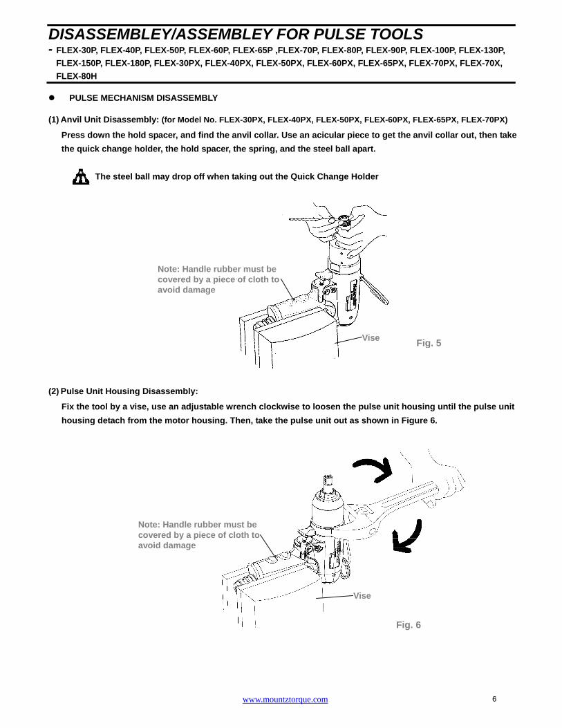
(1) Anvil Unit Disassembly: (for Model No. FLEX-30PX, FLEX-40PX, FLEX-50PX, FLEX-60PX, FLEX-65PX, FLEX-70PX)
Press down the hold spacer, and find the anvil collar. Use an acicular piece to get the anvil collar out, then take
the quick change holder, the hold spacer, the spring, and the steel ball apart.
The steel ball may drop off when taking out the Quick Change Holder
(2) Pulse Unit Housing Disassembly:
Fix the tool by a vise, use an adjustable wrench clockwise to loosen the pulse unit housing until the pulse unit
housing detach from the motor housing. Then, take the pulse unit out as shown in Figure 6.
ViseFig. 5
Note: Handle rubber must be covered by a piece of cloth to avoid damage
Vise
Note: Handle rubber must be covered by a piece of cloth toavoid damage
Fig. 6
6

www.mountztorque.com
(3) Pulse Unit Disassembly:
Fix the pulse unit by a vise. Use the appliance (see Table 1) to loosen the lock nut on the pulse unit, Fig. 7.
Note: Lock-tite was applied on the luck nut when tools were assembled.
Put the Appliance, see Table 2, on the anvil and tap on it slightly to detach the interior parts from the pulse unit,
Fig. 8.
Appliance No. Apply to
63-40RT001 FLEX-30P, FLEX-30PX, FLEX-40P, FLEX-40PX,
FLEX-50P, FLEX-50PX, FLEX-60P, FLEX-60PX
63-70RT001 FLEX-65P, FLEX-65PX, FLEX-70P, FLEX-70PX,
FLEX-70X, FLEX-80P, FLEX-80H
63-90RT001 FLEX-90P
63-100RT001 FLEX-100P
63-130RT001 FLEX-130P
63-150RT001 FLEX-150P, FLEX-180P
Appliance No. Apply to
63-40RT002
FLEX-30P, FLEX-30PX, FLEX-40P, FLEX-40PX,
FLEX-50P, FLEX-50PX, FLEX-60P, FLEX-60PX,
FLEX-65P, FLEX-65PX, FLEX-70P, FLEX-70PX,
FLEX-70X, FLEX-80P
63-90RT002 FLEX-80H, FLEX-90P, FLEX-100P, FLEX-130P
63-150RT002 FLEX-150P
63-180RT002 FLEX-180P
Fig. 8
Table1
Table 2
Fig. 7
Appliance
Appliance
7
www.mountztorque.com
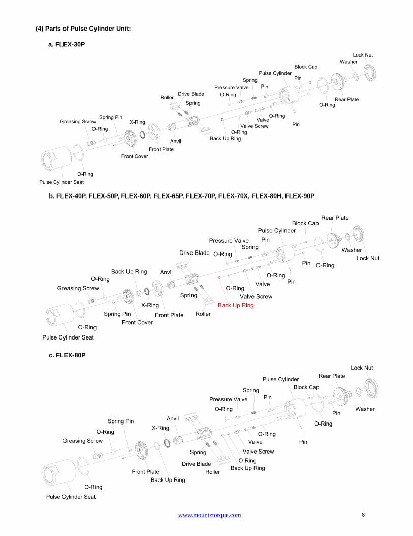
(4) Parts of Pulse Cylinder Unit:
a. FLEX-30P
b. FLEX-40P, FLEX-50P, FLEX-60P, FLEX-65P, FLEX-70P, FLEX-70X, FLEX-80H, FLEX-90P
c. FLEX-80P
Lock NutWasher
Rear PlateO-Ring
Block Cap
PinPulse Cylinder
PinSpring
Pressure ValveO-Ring
Pin
O-RingValve
Valve ScrewO-Ring
Back Up Ring
Spring
Drive BladeRoller
AnvilFront Plate
X-Ring
Front Cover
Spring Pin
O-RingGreasing Screw
O-RingPulse Cylinder Seat
Lock NutWasher
Rear Plate
O-Ring
Block Cap
Pin
Pin
Pulse CylinderPin
SpringPressure Valve
O-Ring
O-Ring
Valve
Valve ScrewO-Ring
Roller
Spring
Drive Blade
Anvil
Front PlateX-Ring
Back Up Ring
Front CoverSpring Pin
O-RingGreasing Screw
O-Ring
Pulse Cylinder Seat
Back Up Ring
Lock Nut
Washer
Rear Plate
Pin
O-Ring
Block Cap
Pin
Pulse Cylinder
PinSpring
Pressure Valve
O-Ring
O-RingValve
Valve ScrewO-Ring
Back Up RingRoller
Drive Blade
Spring
AnvilX-Ring
Back Up RingFront Plate
Spring Pin
O-RingGreasing Screw
O-Ring
Pulse Cylinder Seat
8

www.mountztorque.com
Lock Nut
Washer
Rear Plate
O-Ring
Block Cap
Pin
Pulse CylinderPin
SpringPressure Valve
O-Ring
Roller
Drive Blade
Spring
Anvil
X-Ring
Back Up RingPin
O-RingGreasing Screw
O-Ring
ValveValve ScrewO-Ring
Back Up Ring
Front Plate
PinO-Ring
Pulse Cylinder Seat
Lock Nut
Washer
Rear Plate
O-Ring
Block Cap
Pin
Pulse Cylinder
PinSpring
Pressure ValveO-Ring
AnvilX-Ring
Back Up RingPin
O-Ring
Greasing Screw
Spring
Drive BladeRoller
O-RingValve
Valve ScrewO-Ring
Front Plate
PinO-Ring
Pulse Cylinder Seat
d. FLEX-100P
e. FLEX-130P
f. FLEX-150P, FLEX-180P
Pulse Cylinder Seat
O-RingSnap Ring
Washer
Back Up RingX-Ring Pin
Front Plate
Back Up RingO-Ring
Valve Screw
Spring
Greasing ScrewO-Ring
Anvil
RollerDrive Blade
ValveO-Ring
O-Ring
Pin
Pulse Cylinder
Pin
PinSpring
Valve
Back Up Ring
Block CapO-Ring
Rear Plate
Washer
Lock Nut
9

www.mountztorque.com
g. FLEX-30PX
h. FLEX-40PX, FLEX-50PX, FLEX-60PX, FLEX-65PX, FLEX-70PX
PULSE UNIT ASSEMBLY:
(1) Pulse Cylinder Unit Assembly:
Install the pins on both sides of the pulse cylinder. (Fig. 9)
Sleeve the o-ring to the valve and install the valve into the big hole on the pulse cylinder. (Step 1; Fig.10)
Insert the pin into the hole on the side of the pulse cylinder. (Step 2; Fig.11)
Tighten the valve screw left thread to the pressure valve. (Step 3; Fig.11)
NOTE: the valve screw MUST tighten to the most bottom position certainly.
Lock Nut
Washer
Rear Plate
O-Ring
Block Cap
Pin
Pulse Cylinder
Pin
O-RingValve
Valve ScrewO-Ring
PinSpring
Pressure ValveO-Ring
Spring
Drive BladeRoller
Anvil
Steel BallFront Plate
X-Ring
Front CoverSpring Pin
O-RingGreasing Screw
O-Ring
Pulse Cylinder Seat
Back Up Ring
Lock NutWasher
Rear PlateO-Ring
Block CapPin
Pin
Pulse Cylinder
PinSpring
Pressure ValveO-Ring
O-RingValve
Valve ScrewO-Ring
Anvil
Steel Ball
Spring
Drive BladeRoller
Front Plate
X-Ring
Back Up Ring
Front CoverSpring Pin
O-RingGreasing Screw
O-Ring
Pulse Cylinder Seat
Back Up Ring
Pin
Pin
Pulse Cylinder Fig. 9
10

www.mountztorque.com
Valve Screw
Step 2; Fig. 11
Pin
Pressure Valve
Spring
Step 4; Fig. 12
Put the spring into the hole then install the pressure valve that with the o-ring sleeved. (Step 4; Fig. 12)
Install the front plate and make sure the corresponding position with the pins. (Step 5; Fig. 13)
(2) Anvil Unit Assembly:
Install the roller to the drive blade, then insert the springs into the anvil and press the blades from both sides.
Finally put the anvil to the pulse cylinder to complete the anvil unit assembly.
MUST follow the direction as shown in Figure 16 while installing the anvil unit into the pulse cylinder; be sure
to aim at the highest points by two sides of the interior pulse unit and press the two drive blades in slowly.
Small Hole
Big Hole
O-ring
Step 1; Fig. 10
Step 5; Fig. 13
Front Plate
Corresponding position
11

Fig. 16
Front Plate
Fig. 15
Press
Press Spring
Fig. 14
Roller
Drive Blade
12

www.mountztorque.com
X-ring
(d) Fig. 25
(d) Fig. 20
(3) Front Cover and Rear Plate of Pulse Cylinder Assembly
FLEX-30P, FLEX-30PX
(a) Put the O-ring on the Rear Plate and install the rear plate to the pulse cylinder, Be sure the positions of the
pin and the hole are corresponded. (Fig. 17)
(b) Put the X-ring on the anvil with the oil applied. (Fig. 18)
(c) Put the Back up ring and O-ring into the Valve Screw. (Fig. 19)
(d) Install the front cover to the pulse cylinder by the corresponding positions. (Fig. 20)
After installing the front cover, put the o-ring on the greasing screw, then tighten the greasing screw but
release it a little bit after completely tightened.
FLEX-40P, FLEX-40PX, FLEX-50P, FLEX-50PX, FLEX-60P, FLEX-60PX, FLEX-65P, FLEX-65PX, FLEX-70P,
FLEX-70PX, FLEX-70X, FLEX-80H, FLEX-90P
(a) Put the O-ring on the Rear Plate and install the rear plate to the pulse cylinder, Be sure the positions of the
pin and the hole are corresponded. (Fig. 22)
(b) Put the X-ring and Back up ring on the anvil with the oil applied. (Fig.23)
(c) Put the Back up ring and O-ring into the Valve Screw. (Fig. 24)
(d) Install the front cover to the pulse cylinder by the corresponding positions. (Fig. 25)
O-ring
Rear Plate
(a) Fig. 17 (b) Fig. 18
Corresponding position
Front Cover
O-ring
Greasing Screw
Fig. 21
Rear Plate
O-ring
(a) Fig. 22 (b) Fig. 23
Back Up Ring
X-ring
Front Cover
(c) Fig. 19
Back Up Ring
O-ring
(c) Fig. 24
Back Up Ring
O-ring
Corresponding position
13

www.mountztorque.com
After installing the front cover, put the o-ring on the greasing screw, then tighten the greasing screw but
release it a little bit after completely tightened.
FLEX-80P
(a) Put the O-ring on the Rear Plate and install the rear plate to the pulse cylinder, Be sure the positions of the
pin and the hole are corresponded. (Fig. 27)
(b) Put the X-ring and Back up ring on the anvil with the oil applied. (Fig. 28)
(c) Put the Back up ring and O-ring into the Valve Screw. (Fig. 29)
(d) Install the front plate to the pulse cylinder by the corresponding positions. (Fig. 30)
After installing the front cover, put the o-ring on the greasing screw, then tighten the greasing screw but
release it a little bit after completely tightened.
FLEX-100P
(a) Put the O-ring on the Rear Plate and install the rear plate to the pulse cylinder, Be sure the positions of the
pin and the hole are corresponded. (Fig. 32)
(b) Put the X-ring and Back up ring on the anvil with the oil applied. (Fig. 33)
(c) Put the O-ring into the Valve Screw. (Fig. 34)
(d) Install the front plate to the pulse cylinder by the corresponding positions. (Fig. 35)
O-ring
Rear Plate
(a) Fig. 27
Front Plate
Corresponding position
(d) Fig. 30 (c) Fig. 29
Back Up Ring O-ring
X-ring
(b) Fig. 28
Fig. 31
Greasing Screw
O-ring Fig. 26
O-ring
Greasing Screw
Back Up Ring
14

www.mountztorque.com
After installing the front cover, put the o-ring on the greasing screw, then tighten the greasing screw but
release it a little bit after completely tightened.
FLEX-130P
(a) Put the O-ring on the Rear Plate and install the rear plate to the pulse cylinder, Be sure the positions of the
pin and the hole are corresponded. (Fig. 37)
(b) Put the X-ring and Back up ring on the anvil with the oil applied. (Fig. 38)
(c) Put the Back up ring and O-ring into the Valve Screw. (Fig. 39)
(d) Install the front plate to the pulse cylinder by the corresponding positions. (Fig. 40)
After installing the front cover, put the o-ring on the greasing screw, then tighten the greasing screw but
release it a little bit after completely tightened.
(a) Fig. 32
(a) Fig. 37
O-ring
Rear Plate
O-ring
(c) Fig. 34
Front Plate
Corresponding position
(d) Fig. 35
O-ring
Rear Plate
(c) Fig. 39 (d) Fig. 40
Front Plate
Corresponding position
O-ring
X-ring
(b) Fig. 33
Greasing Screw O-ring Fig. 36
X-ring
(b) Fig. 38
Greasing Screw
O-ring Fig. 41
Back Up Ring
Back Up Ring
Back Up Ring
15

www.mountztorque.com
Half-circle gaps
Pin
O-ring Fig. 48
Pulse Cylinder Seat
Greasing screw
FLEX-150P, FLEX-180P
(a) Put the O-ring on the Rear Plate and install the rear plate to the pulse cylinder, Be sure the positions of the
pin and the hole are corresponded. (Fig. 42)
(b) Put the O-ring into the Valve Screw. (Fig. 43)
(c) Put the X-ring and Back Up Ring , Washer , Snap Ring on the anvil with the oil applied. (Fig. 44)
(d) Install the front plate to the pulse cylinder by the corresponding positions. (Fig. 45)
After installing the front cover, put the o-ring on the greasing screw, then tighten the greasing screw but
release it a little bit after completely tightened.
(4) Pulse Cylinder Seat and Lock Nut of Pulse Cylinder Assembly
Place the o-ring inside the bottom of the pulse cylinder seat, then
combine the pulse cylinder seat with the assembled pulse cylinder
unit. (Fig. 47, Fig. 48)
Make sure the half-circle gaps aim at the corresponding positions.
O-ring
Rear Plate Back Up Ring
Front Plate
X-ring
Back Up Ring
Washer Snap Ring
Corresponding position Front Plate
(a) Fig. 42 (b) Fig. 43 (c) Fig. 44 (d) Fig. 45
Fig. 47
O-ring
Pulse Cylinder Seat
O-ring
Greasing Screw
O-ring Fig. 46
16

www.mountztorque.com
Use the appliance to push out the rear plate from the pulse cylinder seat. See Table 2 in reference to the
proper appliance selection. (Fig. 49)
Fill up the interior pulse cylinder with the pulse oil about 90% full by an injector. (Fig. 50)
Install the rear plate taken from the step 2 on the pulse cylinder. Note the corresponding positions!
Turn the assembled unit up side down so the rear plate is at the bottom. Then press the pulse cylinder seat
all the way down to the fixed position. Make sure the corresponding positions are matched exactly.
Fix the pulse cylinder seat by a vise. Use an appliance and a torque wrench then turn clockwise to tighten
the lock nut of the pulse cylinder. See Table 3 and Table 4 in reference to the proper appliance and tightness.
(Note: Lock-tite needed when tightening the lock nut of the pulse cylinder)
Appliance No. Apply to
63-40RT001
FLEX-30P, FLEX-30PX, FLEX-40P,
FLEX-40PX, FLEX-50P, FLEX-50PX, FLEX-60P, FLEX-60PX
63-70RT001
FLEX-65P, FLEX-65PX, FLEX-70P, FLEX-70PX, FLEX-70X, FLEX-80P, FLEX-80H
63-90RT001 FLEX-90P
63-100RT001 FLEX-100P
63-130RT001 FLEX-130P
63-150RT001 FLEX-150P, FLEX-180P
Table 3
Fig. 50 Fig. 52Fig. 51
Appliance
Fig. 53 Fixed by a vise
Fig. 49
Appliance
Rear Plate Rear Plate
17
www.mountztorque.com
Fig. 54
Fig. 55
Fig. 56
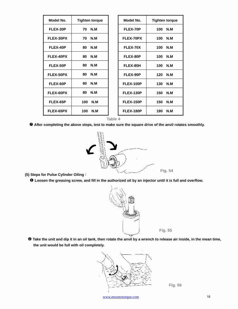
After completing the above steps, test to make sure the square drive of the anvil rotates smoothly.
(5) Steps for Pulse Cylinder Oiling:
Loosen the greasing screw, and fill in the authorized oil by an injector until it is full and overflow.
Take the unit and dip it in an oil tank, then rotate the anvil by a wrench to release air inside, in the mean time,
the unit would be full with oil completely.
Model No. Tighten torque
FLEX-30P 70 N.M
FLEX-30PX 70 N.M
FLEX-40P 80 N.M
FLEX-40PX 80 N.M
FLEX-50P 80 N.M
FLEX-50PX 80 N.M
FLEX-60P 80 N.M
FLEX-60PX 80 N.M
FLEX-65P 100 N.M
FLEX-65PX 100 N.M
Model No. Tighten torque
FLEX-70P 100 N.M
FLEX-70PX 100 N.M
FLEX-70X 100 N.M
FLEX-80P 100 N.M
FLEX-80H 100 N.M
FLEX-90P 120 N.M
FLEX-100P 130 N.M
FLEX-130P 150 N.M
FLEX-150P 150 N.M
FLEX-180P 180 N.M
Table 4
18

www.mountztorque.com
Use the screwdriver either, the slotted or the hex one to tighten the greasing screw, Fig. 57.
Use an air spray gun to blow off the oil on the cylinder seat, Fig. 58.
Loosen the greasing screw again and use
an injector to draw out a little amount of oil ( see Table 5)
Finally, tighten the greasing screw back to
the pulse cylinder unit, Fig. 59.
Model No. Amount of oil draw
FLEX-30P 0.25 CC
FLEX-30PX 0.25 CC
FLEX-40P 0.3 CC
FLEX-40PX 0.3 CC
FLEX-50P 0.35 CC
FLEX-50PX 0.35 CC
FLEX-60P 0.45 CC
FLEX-60PX 0.45 CC
FLEX-65P 0.6 CC
FLEX-65PX 0.6 CC
Model No. Amount of oil draw
FLEX-70P 0.63 CC
FLEX-70PX 0.63 CC
FLEX-70X 0.63 CC
FLEX-80P 0.6 CC
FLEX-80H 0.56 CC
FLEX-90P 0.9 CC
FLEX-100P 1.5 CC
FLEX-130P 1.6 CC
FLEX-150P 2.2 CC
FLEX-180P 2.5 CC
Fig. 57
Fig. 59
Table 5
Fig. 58
Slotted
O-ring
Greasing Screw
Hex
O-ring
Greasing Screw
19

www.mountztorque.com
Fig. 61
Wrench series Driver series
(6) Torque Testing:
Put the washer on the front end of the anvil, and then put another washer on the rear plate.
Tighten the clutch housing by hands.
Test the forward torque by a digital torque tester and make sure the tool pulses smoothly.
Fig. 62
Fig. 60
Washer
Anvil
Washer
Rear Plate
Digital Torque Tester
20

www.mountztorque.com
If the test result is NG (see Table 6 in reference to the torque standard), MUST draw out or add a little
amount of oil and do the following steps:
Loosen the pulse unit housing by hands.
Loosen the greasing screw.
Draw out or add a little amount of oil.
Tighten the greasing screw back.
Tighten the pulse unit housing.
Test the torque again. If the test result is still NG, repeat the Steps ~until the standard torque
is reached.
(7) Pulse Unit Housing Assembly:
Fix the housing by a vise. Turn the wrench in counter clockwise direction to tighten the pulse unit housing.
Model No. Air inlet pressure 0.6 Mpa
N.M (at least)
FLEX-30P 12.5
FLEX-30PX 12.5
FLEX-40P 19
FLEX-40PX 18
FLEX-50P 27
FLEX-50PX 26
FLEX-60P 35
FLEX-60PX 30
FLEX-65P 45
FLEX-65PX 38
Model No. Air inlet pressure 0.6 Mpa
N.M (at least)
FLEX-70P 57
FLEX-70PX 47
FLEX-70X 55
FLEX-80P 70
FLEX-80H 72
FLEX-90P 90
FLEX-100P 120
FLEX-130P 148
FLEX-150P 210
FLEX-180P 255
Table 6
Note: Handle rubber must be covered by a piece of cloth toavoid damage
Fig. 63
21

www.mountztorque.com
(8) Anvil Unit Assembly: (for FLEX-30PX, FLEX-40PX, FLEX-50PX, FLEX-60PX, FLEX-65PX, FLEX-70PX)
(a) Place the steel ball, the quick change holder, the spring, and the hold spacer orderly on the anvil as shown.
(b) Put the anvil collar on the Anvil. (Fig. 65)
HOUSING AND MOTOR SET DISASSEMBLY:
(1) Cylinder Unit Disassembly:
Take a piece of cloth to cover the housing handle and fix the tool with a vise. Use the appliance (see Table 7) to
take the lock nut out of cylinder by turning clockwise.
Appliance No. Apply to
63-40RT004
FLEX-30P, FLEX-30PX, FLEX-40P,
FLEX-40PX, FLEX-50P, FLEX-50PX,
FLEX-60P, FLEX-60PX
63-70XRT004 FLEX-65P, FLEX-65PX, FLEX-70X FLEX-80P, FLEX-80H
63-90RT003 FLEX-70P, FLEX-70PX, FLEX-90P
63-100RT003 FLEX-100P
63-130RT003 FLEX-130P
63-150RT003 FLEX-150P
Lock Nut of Cylinder
Table 7
Fig. 65
Anvil Collar
Hex-hole of Anvil
Appliance
Note: Handle rubber must be covered by a piece of cloth to avoid damage
Fig. 66
Hold Spacer
Spring
Quick Change Holder
Steel Ball Anvil
Fig. 64
22
www.mountztorque.com
Fig. 67
Note: Handle rubber must be
covered by a piece of cloth to
avoid damage
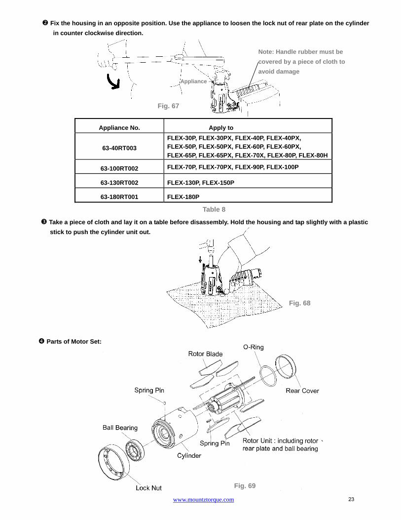
Fix the housing in an opposite position. Use the appliance to loosen the lock nut of rear plate on the cylinder
in counter clockwise direction.
Take a piece of cloth and lay it on a table before disassembly. Hold the housing and tap slightly with a plastic
stick to push the cylinder unit out.
Parts of Motor Set:
Appliance No. Apply to
63-40RT003
FLEX-30P, FLEX-30PX, FLEX-40P, FLEX-40PX, FLEX-50P, FLEX-50PX, FLEX-60P, FLEX-60PX,
FLEX-65P, FLEX-65PX, FLEX-70X, FLEX-80P, FLEX-80H
63-100RT002 FLEX-70P, FLEX-70PX, FLEX-90P, FLEX-100P
63-130RT002 FLEX-130P, FLEX-150P
63-180RT001 FLEX-180P
Fig. 69
Table 8
Fig. 68
Appliance
23

www.mountztorque.com
Fig. 70
The rotor and the rear end plate must be press fitted. The clearance of the two parts must be in between 0.01~
0.02 mm. It would not be easy to assemble the two parts by repair centers in general. Therefore, as there is a
need of repair on the parts of the rotor, the rear end plate, and the ball bearing, we strongly suggest replacing
a complete ROTOR UNIT, which is including the rotor, the rear plate, and the ball bearing. The rotor unit would
be full assembled and well-measured before delivery.
(2) Air Inlet Disassembly:
Take the air inlet unit apart from the end of the housing. The parts of O-ring, Muffler, Exhaust deflector
are separated by each other.
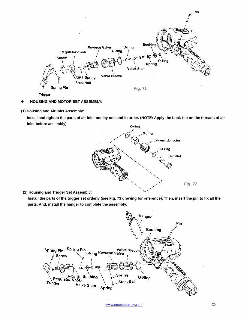
(3) Trigger Set Disassembly:
Remove the pin to take apart the valve sleeve set. All the parts are disassembled as the below drawing shown.
24
www.mountztorque.com
Fig. 72
HOUSING AND MOTOR SET ASSEMBLY:
(1) Housing and Air Inlet Assembly:
Install and tighten the parts of air inlet one by one and in order. (NOTE: Apply the Lock-tite on the threads of air
inlet before assembly)
(2) Housing and Trigger Set Assembly:
Install the parts of the trigger set orderly (see Fig. 73 drawing for reference). Then, insert the pin to fix all the
parts. And, install the hanger to complete the assembly.
Fig. 71
25

www.mountztorque.com
(3) Cylinder Unit Assembly
Place the rotor blades into the rotor. Insert the spring pin A and B into the cylinder. Make sure the pins aim
at the pin holes when putting the cylinder down.
Install the o-ring and the rear cover to the rear plate. The motor set assembly is completed.
Fig. 74
Fig. 75
Fig. 73
Rotor unitSpring Pin A
Spring Pin B
O-Ring
Rear Cover
26
www.mountztorque.com
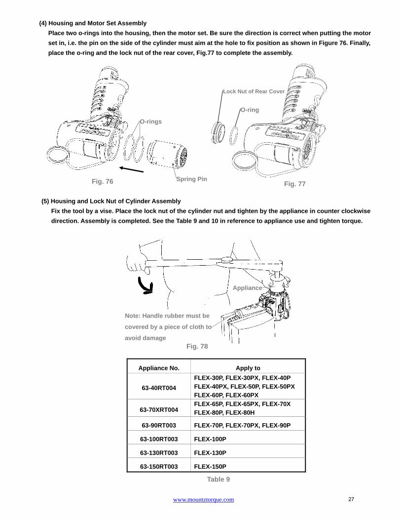
(4) Housing and Motor Set Assembly
Place two o-rings into the housing, then the motor set. Be sure the direction is correct when putting the motor
set in, i.e. the pin on the side of the cylinder must aim at the hole to fix position as shown in Figure 76. Finally,
place the o-ring and the lock nut of the rear cover, Fig.77 to complete the assembly.
(5) Housing and Lock Nut of Cylinder Assembly
Fix the tool by a vise. Place the lock nut of the cylinder nut and tighten by the appliance in counter clockwise
direction. Assembly is completed. See the Table 9 and 10 in reference to appliance use and tighten torque.
Appliance No. Apply to
63-40RT004
FLEX-30P, FLEX-30PX, FLEX-40P
FLEX-40PX, FLEX-50P, FLEX-50PX FLEX-60P, FLEX-60PX
63-70XRT004 FLEX-65P, FLEX-65PX, FLEX-70X FLEX-80P, FLEX-80H
63-90RT003 FLEX-70P, FLEX-70PX, FLEX-90P
63-100RT003 FLEX-100P
63-130RT003 FLEX-130P
63-150RT003 FLEX-150P
Table 9
Fig. 76
O-rings
Spring Pin
Lock Nut of Rear Cover
O-ring
Fig. 77
Appliance
Note: Handle rubber must be
covered by a piece of cloth to
avoid damage Fig. 78
27

www.mountztorque.com
FLEX-180P
HOUSING AND MOTOR SET DISASSEMBLY:
(1) Cylinder Unit Disassembly
Take out the lock washer.
Fix the housing in an opposite position. Use the appliance to loosen the lock nut of rear plate on the cylinder
in counter clockwise direction.
Model No. Tighten torque
FLEX-30P 40 N.M
FLEX-30PX 40 N.M
FLEX-40P 40 N.M
FLEX-40PX 40 N.M
FLEX-50P 40 N.M
FLEX-50PX 40 N.M
FLEX-60P 40 N.M
FLEX-60PX 40 N.M
FLEX-65P 40 N.M
FLEX-65PX 40 N.M
Model No. Tighten torque
FLEX-70P 60 N.M
FLEX-70PX 60 N.M
FLEX-70X 40 N.M
FLEX-80P 40 N.M
FLEX-80H 40 N.M
FLEX-90P 60 N.M
FLEX-100P 60 N.M
FLEX-130P 80 N.M
FLEX-150P 60 N.M
Table 10
Fig. 79
Fig. 80
Note: Handle rubber must be
covered by a piece of cloth
to avoid damage
Appliance
Lock washer
28

www.mountztorque.com
Take a piece of cloth and lay it on a table before disassembly. Hold the housing and tap slightly with a plastic
stick to push the cylinder unit out.
Parts of Motor Set:
The rotor and the rear end plate must be press fitted. The clearance of the two parts must be in between 0.01~
0.02 mm. It would not be easy to assemble the two parts by repair centers in general. Therefore, as there is a
need of repair on the parts of the rotor, the rear end plate, and the ball bearing, we strongly suggest replacing
a complete ROTOR UNIT, which is including the rotor, the rear plate, and the ball bearing. The rotor unit would
be full assembled and well-measured before delivery.
Appliance No. Apply to
63-180RT001 FLEX-180P
Table 11
Fig. 81
Fig. 82
29

www.mountztorque.com
(2) Air Inlet Disassembly:
Take the air inlet unit apart from the end of the housing. The parts of O-ring, Muffler, Exhaust deflector
are separated by each other.
(3) Trigger Set Disassembly:
Remove the pin to take apart the valve sleeve set. All the parts are disassembled as the below drawing showed.
Fig. 83
Fig. 84
30

www.mountztorque.com
HOUSING AND MOTOR SET ASSEMBLY:
(1) Housing and Air Inlet Assembly:
Install and tighten the parts of air inlet one by one and in order. (NOTE: Apply the Lock-tite on the threads of air
inlet before assembly)
(2) Housing and Trigger Set Assembly:
Install the parts of the trigger set orderly (see Fig. 86 drawing for reference). Then, insert the pin to fix all the
parts. And, install the hanger to complete the assembly.
(3) Cylinder Unit Assembly
Place the rotor blades into the rotor. Insert the spring pin A and B into the cylinder. Make sure the pins aim
at the pin holes when putting the cylinder down.
Fig. 85
Fig. 86
Spring pin B
Spring pin A Rotor unit
Fig. 87
31

www.mountztorque.com
Install the o-ring and the rear cover to the rear plate. The motor set assembly is completed.
(4) Housing and Motor Set Assembly
Place two o-rings into the housing, then the motor set. Be sure the direction is correct when putting the motor
set in, i.e. the pin on the side of the cylinder must aim at the hole to fix position as Fig. 89 showed. Finally, place
the o-ring and the lock nut of the rear cover, Fig. 90 to complete the assembly.
(5) Motor housing, Pulse Unit, and Pulse Unit Housing Assembly
(a) Put the lock washer into the housing. (Fig. 91)
(b) Put the pulse unit, washer, pulse unit housing in order. (Fig. 92)
(c) Lock up the housings with 3 screws, Please refer to Table 12 for the tighten torque of screws.
NOTE : The 3 screws must be applied with loc-tite.
Model No. Tighten torque
FLEX-180P 15 N.M
Fig. 91 Fig. 92 Fig. 93
Table 12
O-Ring
Rear Cover
Fig. 88
O-ring
Lock Nut of Rear Cover
Fig. 89 Fig. 90
32

www.mountztorque.com
After all the assembly is complete, test to make sure the anvil rotates smoothly, then connect the air hose
to test the torque.
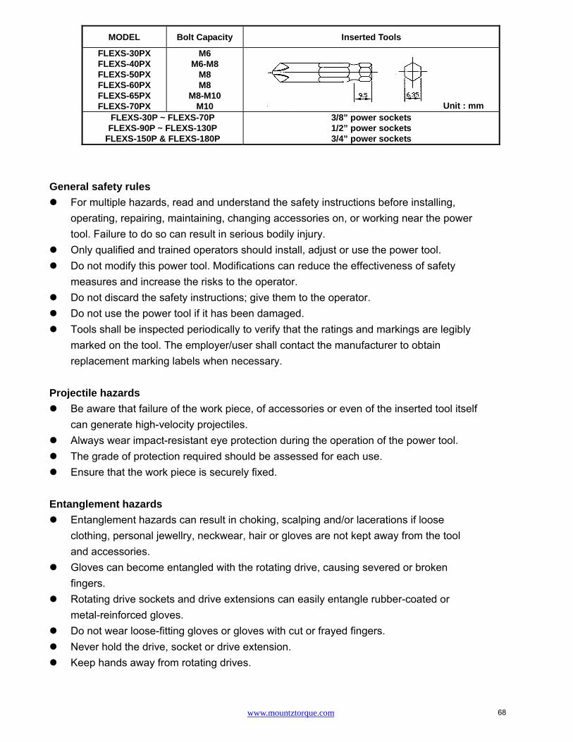
General safety rules
For multiple hazards, read and understand the safety instructions before installing,operating, repairing, maintaining, changing accessories on, or working near the powertool. Failure to do so can result in serious bodily injury.
Only qualified and trained operators should install, adjust or use the power tool. Do not modify this power tool. Modifications can reduce the effectiveness of safety
measures and increase the risks to the operator. Do not discard the safety instructions; give them to the operator. Do not use the power tool if it has been damaged. Tools shall be inspected periodically to verify that the ratings and markings are legibly
marked on the tool. The employer/user shall contact the manufacturer to obtainreplacement marking labels when necessary.
Projectile hazards
Be aware that failure of the work piece, of accessories or even of the inserted tool itself
MODEL Bolt Capacity Inserted Tools
FLEX-30PX FLEX-40PX FLEX-50PX FLEX-60PX FLEX-65PX FLEX-70PX
M6 M6-M8
M8 M8
M8-M10 M10 Unit : mm
FLEX-30P ~ FLEX-70P FLEX-90P ~ FLEX-130P
FLEX-150P & FLEX-180P
3/8” power sockets 1/2” power sockets 3/4” power sockets
Fig. 94
33

www.mountztorque.com
can generate high-velocity projectiles. Always wear impact-resistant eye protection during the operation of the power tool. The grade of protection required should be assessed for each use. Ensure that the work piece is securely fixed.
Entanglement hazards
Entanglement hazards can result in choking, scalping and/or lacerations if looseclothing, personal jewellry, neckwear, hair or gloves are not kept away from the tooland accessories.
Gloves can become entangled with the rotating drive, causing severed or brokenfingers.
Rotating drive sockets and drive extensions can easily entangle rubber-coated ormetal-reinforced gloves.
Do not wear loose-fitting gloves or gloves with cut or frayed fingers. Never hold the drive, socket or drive extension. Keep hands away from rotating drives.
Operating hazards
The use of the tool can expose the operator's hands to hazards including crushing,impacts, cuts, abrasions and heat. Wear suitable gloves to protect hands.
Operators and maintenance personnel shall be physically able to handle the bulk,weight and power of the tool.
Hold the tool correctly; be ready to counteract normal or sudden movements and haveboth hands available.
Maintain a balanced body position and secure footing. In cases where the means to absorb the reaction torque are requested, it is
recommended to use a suspension arm whenever possible. If that is not possible, sidehandles are recommended for straight case and pistol-grip tools. Reaction bars arerecommended for angle nut runners. In any case, it is recommended to use a means toabsorb the reaction torque above 4 Nm for straight tools, above 10 Nm for pistol-griptools, and above 60 Nm for angle nut runners.
Release the start-and-stop device in the case of an interruption of the energy supply. Use only lubricants recommended by the manufacturer. Fingers can be crushed in open-ended crow-foot nut runners. Do not use in confined spaces and beware of crushing hands between tool and
work piece, especially when unscrewing.
Repetitive motions hazards
When using a power tool, the operator can experience discomfort in the hands, arms,shoulders, neck, or other parts of the body.
While using a power tool, the operator should adopt a comfortable posture whilstmaintaining secure footing and avoiding awkward or off-balanced postures. The operator should
34

www.mountztorque.com
change posture during extended tasks, which can help avoid discomfort and fatigue. If the operator experiences symptoms such as persistent or recurring discomfort, pain, throbbing,
aching, tingling, numbness, burning sensations or stiffness, these warning signs should not beignored. The operator should tell the employer and consult a
qualified health professional.
Accessory hazards
Disconnect the power tool from the energy supply before changing the inserted tool oraccessory.
Do not touch sockets or accessories during impacting, as this increases the risk ofcuts, burns or vibration injuries.
Use only sizes and types of accessories and consumables that are recommended bythe power tool manufacturer.
Use only impact-wrench-rated sockets in good condition, as poor condition or handsockets and accessories used with impact wrenches can shatter and become aprojectile.
Workplace hazards
Slips, trips and falls are major causes of workplace injury. Be aware of slipperysurfaces caused by the use of the tool and also of trip hazards caused by the air line orhydraulic hose.
Proceed with care in unfamiliar surroundings. Hidden hazards, such as electricity orother utility lines, can exist.
The power tool is not intended for use in potentially explosive atmospheres and is not insulated against coming into contact with electric power. Make sure there are no electrical cables, gas pipes, etc., that can cause a hazard if
damaged by use of the tool.
Dust and fume hazards
Dust and fumes generated when using power tools can cause ill health (for example,cancer, birth defects, asthma and/or dermatitis); risk assessment and implementationof appropriate controls for these hazards are essential.
Risk assessment should include dust created by the use of the tool and the potentialfor disturbing existing dust.
Direct the exhaust so as to minimize disturbance of dust in a dust-filled environment. Where dust or fumes are created, the priority shall be to control them at the point of
emission. All integral features or accessories for the collection, extraction or suppression of
airborne dust or fumes should be correctly used and maintained in accordance withthe manufacturer's instructions.
Use respiratory protection in accordance with employer's instructions and as requiredby occupational health and safety regulations.
35

www.mountztorque.com
Noise hazards
Unprotected exposure to high noise levels can cause permanent, disabling, hearingloss and other problems, such as tinnitus (ringing, buzzing, whistling or humming inthe ears).
Risk assessment and implementation of appropriate controls for these hazards areessential.
Appropriate controls to reduce the risk may include actions such as damping materialsto prevent work pieces from “ringing”.
Use hearing protection in accordance with employer's instructions and as required byoccupational health and safety regulations.
Operate and maintain the power tool as recommended in the instruction handbook, toprevent an unnecessary increase in noise levels.
If the power tool has a silencer, always ensure it is in place and in good working orderwhen the power tool is operating.
Select, maintain and replace the consumable/inserted tool as recommended in theinstruction hand book, to prevent an unnecessary increase in noise.
Vibration hazards
Exposure to vibration can cause disabling damage to the nerves and blood supply ofthe hands and arms.
Keep the hands away from the nut runner sockets. Wear warm clothing when working in cold conditions and keep your hands warm and
dry. If you experience numbness, tingling, pain or whitening of the skin in your fingers or
hands, stop using the power tool, tell your employer and consult a physician. Operate and maintain the power tool as recommended in the instruction handbook, to
prevent an unnecessary increase in vibration levels. Do not use worn or ill-fitting sockets or extensions, as this is likely to cause a
substantial increase in vibration. Select, maintain and replace the consumable/inserted tool as recommended in the instruction handbook, to prevent an unnecessary increase in vibration levels. Sleeve fittings should be used where practicable. Support the weight of the tool in a stand, tensioner or balancer, if possible. Hold the tool with a light but safe grip, taking account of the required hand reaction
forces, because the risk from vibration is generally greater when the grip force is higher.
Additional safety instructions for pneumatic power tool
Air under pressure can cause severe injury Always shut off air supply, drain hose of air pressure and disconnect tool from air
supply when not in use, before changing accessories or when making repairs Never direct air at yourself or anyone else. Whipping hoses can cause severe injury. Always check for damaged or loose hoses
36

www.mountztorque.com
and fittings. Cold air shall be directed away from the hands. Do not use quick-disconnect couplings at tool inlet for impact and air-hydraulic impulse
wrenches. Use hardened steel (or material with comparable shock resistance)threaded hose fittings.
Whenever universal twist couplings (claw couplings) are used, lock pins shall beinstalled and whipcheck safety cables shall be used to safeguard against possiblehose-to-tool and hose-and-hose connection failure.
Do not exceed the maximum air pressure stated on the tool. For torque-control and continuous-rotation tools, the air pressure has a safety critical
effect on performance. Therefore, requirements for length and diameter of the hose shall be specified.
Never carry an air tool by the hose.
37

www.mountztorque.com
DISASSEMBLEY/ASSEMBLEY FOR PULSE TOOLS - FLEXS-30P, FLEXS-40P, FLEXS-50P, FLEXS-60P, FLEXS-65P, FLEXS-70P, FLEXS-80P, FLEXS-90P, FLEXS-100P,
FLEXS-130P, FLEXS-150P, FLEX-180P, FLEXS-30PX, FLEXS-40PX, FLEXS-50PX, FLEXS-60PX, FLEXS-65PX,
FLEXS-70PX, FLEXS-70X, FLEXS-80H
IMPULSE MECHANISM DISASSEMBLY
(1) Anvil Unit Disassembly: (for Model No. FLEXS-30PX, FLEXS-40PX, FLEXS-50PX, FLEXS-60PX, FLEXS-65PX,
FLEXS-70PX)
Press down the hold spacer, and find the anvil collar. Use an acicular piece to get the anvil collar out, then take
the quick change holder, the hold spacer, the spring, and the steel ball apart.
The steel ball may drop off when taking out the Quick Change Holder
(2) Pulse Unit Housing Disassembly:
Fix the tool by a vise, use an adjustable wrench clockwise to loosen the pulse unit housing until the pulse unit
housing detach from the motor housing. Then, take the pulse unit out, Fig 96.
Vise
Fig. 95
Note: Handle rubber must be covered by a piece of cloth to avoid damage
Vise
Note: Handle rubber must be covered by a piece of cloth to avoid damage
Fig. 96
38

www.mountztorque.com
(3) Pulse Unit Disassembly:
Fix the pulse unit by a vise. Use the appliance (see Table 13) to loosen the lock nut on the pulse unit, Fig. 97.
Note: Lock-tite was applied on the luck nut when tools were assembled.
Put the Appliance, see Table 14, on the anvil and tap on it slightly to detach the interior parts from the pulse
unit, Fig. 98.
Appliance No. Apply to
63-40RT001 FLEXS-30P, FLEXS-30PX, FLEXS-40P, FLEXS-40PX,
FLEXS-50P, FLEXS-50PX, FLEXS-60P, FLEXS-60PX
63-70RT001 FLEXS-65P, FLEXS-65PX, FLEXS-70P, FLEXS-70PX,
FLEXS-70X, FLEXS-80P, FLEXS-80H
63-90RT001 FLEXS-90P
63-100RT001 FLEXS-100P
63-130RT001 FLEXS-130P
63-150RT001 FLEXS-150P, FLEXS-180P
Appliance No. Apply to
63-40RT002
FLEXS-30P, FLEXS-30PX, FLEXS-40P
FLEXS-40PX, FLEXS-50P, FLEXS-50PX
FLEXS-60P, FLEXS-60PX, FLEXS-65P
FLEXS-65PX, FLEXS-70P, FLEXS-70PX
FLEXS-70X, FLEXS-80P
63-90RT002 FLEXS-80H, FLEXS-90P, FLEXS-100P,
FLEXS-130P
63-150RT002 FLEXS-150P
63-180RT002 FLEXS-180P Fig. 98
Table13
Table14
Fig. 97
Appliance
Appliance
39

www.mountztorque.com
(4) Parts of Pulse Cylinder Unit:
a. FLEXS-30P
b. FLEXS-40P, FLEXS-50P, FLEXS-60P, FLEXS-65P, FLEXS-70P, FLEXS-70X, FLEXS-80H, FLEXS-90P
c. FLEXS-80P
Lock Nut
Washer
Pressure Valve
O-RingRear Plate
Pin
Block Cap
O-RingPin
Pulse CylinderSpring
Pressure ValveO-Ring
SpringSteel Ball
O-RingValve
Block ValveSpring
Drive BladeRoller
Anvil
Front Plate
Pin
Valve ScrewO-Ring
Back Up Ring
X-Ring
Front CoverO-Ring
Spring PinO-Ring
Greasing Screw
Pulse Cylinder Seat
Lock NutWasher
Pressure Valve
O-Ring
Rear Plate
PinO-Ring
Block Cap
Pin
Pulse Cylinder
Spring
Pressure ValveO-Ring
SpringSteel Ball
O-RingValve
Block ValveSpring
Drive BladeRoller
Anvil
Front PlatePin
Valve Screw
O-RingX-Ring
Back Up Ring
Front Cover
O-Ring
Spring PinO-Ring
Greasing Screw
Pulse Cylinder Seat
Back Up Ring
Lock NutWasher
Pressure Valve
O-Ring
Block Cap
Spring
Pressure ValveO-Ring
Rear Plate
PinO-Ring
Pin
Pulse Cylinder
SpringSteel Ball
O-RingValve
Valve ScrewO-Ring
Back Up Ring
Block ValveSpring
RollerDrive Blade
AnvilX-Ring
Back Up Ring
PinFront PlateO-Ring
Spring PinO-Ring
Greasing Screw
Pulse Cylinder Seat
40

www.mountztorque.com
Lock NutWasher
Pressure Valve
O-RingRear Plate
Block Cap
Spring
Pressure ValveO-Ring
O-RingPin
Pin
Pulse Cylinder
PinSpring
Steel BallO-Ring
Valve
Roller
X-RingBack Up Ring
O-RingGreasing Screw
Block ValveSpring
Drive Blade
Anvil
Valve ScrewO-Ring
Back Up Ring
Front Plate
PinO-Ring
Pulse Cylinder Seat
d. FLEXS-100P
e. FLEXS-130P
f. FLEXS-150P, FLEXS-180P
SpringValve
Back Up RingO-Ring
Lock NutWasher
Pressure Valve
O-RingRear Plate
O-Ring
Pin
Block CapPulse Cylinder
Pin
PinSpring
Steel BallO-Ring
Valve
O-RingOil Plug
Block ValveMain Shaft
Spring
Drive Blade
RollerAdjust Screw
O-RingBack Up RingFront Plate
PinX-Ring
Back Up Ring
Washer
Snap RingO-Ring
Pulse Cylinder Seat
Block Valve
Pressure Valve
Rear Plate
Block Cap
Pulse CylinderPin
Spring
Pressure Valve
O-Ring
Lock NutWasher
O-RingSpring fixed Pin
O-RingPin
Pin
SpringSteel Ball
O-RingValve
Roller
Spring
Drive Blade
Anvil
X-Ring
Back Up RingO-Ring
Greasing Screw
Valve ScrewO-Ring
Front Plate
PinO-RingPulse Cylinder Seat
41

www.mountztorque.com
Valve
Step 2 ; Fig. 101
Pin
Small
Big Hole
Step 1 ; Fig. 100
g. FLEXS-30PX
h. FLEXS-40PX, FLEXS-50PX, FLEXS-60PX, FLEXS-65PX, FLEXS-70PX
PULSE UNIT ASSEMBLY:
(1) Pulse Cylinder Unit Assembly:
Install the pins on both sides of the pulse cylinder. (Fig. 99)
Sleeve the o-ring to the valve and install the valve into the big hole on the pulse cylinder. (Step 1; Fig.100)
Insert the pin into the hole on the side of the pulse cylinder. (Step 2; Fig.101)
Tighten the valve screw left thread to the pressure valve. (Step 3; Fig.101)
NOTE: the valve screw MUST tighten to the most bottom position certainly.
Lock NutWasher
Pressure Valve
O-Ring
Rear Plate
PinO-Ring
Pin
Block Cap
Spring
Pressure ValveO-Ring
Pulse Cylinder
SpringSteel Ball
O-RingValve
Steel Ball
Block Valve
Roller
Spring
Drive Blade
AnvilFront Plate
PinValve Screw
O-Ring
X-Ring
Front Cover
O-Ring
Spring Pin
Pulse Cylinder Seat
Greasing ScrewO-Ring
Back Up Ring
Washer
Pressure Valve
O-Ring
Rear Plate
PinO-Ring
Pin
Block Cap
Spring
Pressure ValveO-Ring Pulse Cylinder
SpringSteel Ball
O-RingValve
Block ValveSpring
Drive BladeRoller
Steel Ball
AnvilFront PlatePinValve Screw
O-Ring
X-RingBack Up Ring
Front CoverO-Ring
Spring PinO-Ring
Greasing Screw
Pulse Cylinder Seat
Lock NutBack Up Ring
Pin
Pin
Pulse Cylinder Fig. 99
42

www.mountztorque.com
Step 5 ; Fig. 103 Front Plate
Corresponding position
Fig. 106
Front Plate
Put the spring into the hole then install the pressure valve that with the o-ring sleeved.(Step 4 Fig. 102)
Install the front plate and make sure the corresponding position with the pins. (Step 5 Fig. 103)
(2) Anvil Unit Assembly:
Install the roller to the drive blade, then insert the springs into the anvil and press the blades from both sides.
Finally put the anvil to the pulse cylinder to complete the anvil unit assembly.
MUST follow the direction as shown in Figure 106 while installing the anvil unit into the pulse cylinder; be sure
to aim at the highest points by two sides of the interior pulse unit and press the two drive blades in slowly.
(3) Front Cover and Rear Plate of Pulse Cylinder Assembly
FLEXS-30P, FLEXS-30PX
(a) Put the O-ring on the Rear Plate and install the rear plate to the pulse cylinder, Be sure the positions of the
pin and the hole are corresponded. (Fig. 107) Then, plug the pressure valve with the convex facing outside
in the hole on the rear plate.
(b) Put the X-ring on the anvil with the oil applied. (Fig. 108)
(c) Put the Back up ring and O-ring into the Valve Screw. (Fig. 109)
(d) Install the front cover to the pulse cylinder by the corresponding positions. (Fig. 110)
Fig. 105
Press
Press Spring
Pressure Valve
Spring
Step 4 ; Fig. 102
Fig. 104
Roller
Drive Blade
43

www.mountztorque.com
(d) Fig. 110
After installing the front cover, put the o-ring on the greasing screw,
then tighten the greasing screw but release it a little bit after
completely tightened.
FLEXS-40P, FLEXS-40PX, FLEXS-50P, FLEXS-50PX, FLEXS-60P, FLEXS-60PX, FLEXS-65P, FLEXS-65PX,
FLEXS-70P, FLEXS-70PX, FLEXS-70X, FLEXS-80H, FLEXS-90P
(a) Put the O-ring on the Rear Plate and install the rear plate to the pulse cylinder, Be sure the positions of the
pin and the hole are corresponded. (Fig. 112) Then, plug the pressure valve with the convex facing outside
in the hole on the rear plate.
(b) Put the X-ring and back up ring on the anvil with the oil applied. (Fig. 113)
(c) Put the Back up ring and O-ring into the Valve Screw. (Fig. 114)
(d) Install the front cover to the pulse cylinder by the corresponding positions. (Fig. 115)
(a) Fig. 107 (b) Fig. 108
X-ring Corresponding position
Back Up Ring
X-ring
Front Cover
(a) Fig. 112 (b) Fig. 113 (d) Fig. 115
Pressure Valve
O-ring
Rear Plate
O-ring
Pressure Valve O-ring
O-ring
Rear Plate
Front Cover
(c) Fig. 109
Back Up Ring
O-ring
Back Up Ring O-ring
(c) Fig. 114
Greasing Screw
O-ring Fig. 111
Corresponding position
44

www.mountztorque.com
After installing the front cover, put the o-ring on the greasing screw,
then tighten the greasing screw but release it a little bit after
completely tightened.
FLEXS-80P
(a) Put the O-ring on the Rear Plate and install the rear plate to the pulse cylinder, Be sure the positions of the
pin and the hole are corresponded. (Fig. 117) Then, plug the pressure valve with the convex facing
outside in the hole on the rear plate.
(b) Put the X-ring and Back up ring on the anvil with the oil applied. (Fig. 118)
(c) Put the Back up ring and O-ring into the Valve Screw. (Fig. 119)
(d) Install the front plate to the pulse cylinder by the corresponding positions. (Fig. 120)
After installing the front cover, put the o-ring on the greasing screw, then tighten the greasing screw but
release it a little bit after completely tightened.
FLEXS-100P
(a) Put the O-ring on the Rear Plate and install the rear plate to the pulse cylinder, Be sure the positions of the
pin and the hole are corresponded. (Fig. 122) Then, plug the pressure valve with the convex facing
outside in the hole on the rear plate.
(b) Put the X-ring and Back up ring on the anvil with the oil applied. (Fig. 123)
(c) Put the O-ring into the Valve Screw. (Fig. 124)
(d) Install the front plate to the pulse cylinder by the corresponding positions. (Fig. 125)
(a) Fig. 117
Front Plate
Corresponding position
(d) Fig. 120 (c) Fig. 119
Pressure Valve O-ring
O-ring
Rear Plate
Back Up Ring O-ring
Fig. 116
X-ring
(b) Fig. 118
Greasing Screw
O-ring Fig. 121
Back Up Ring
Greasing Screw
O-ring
45

www.mountztorque.com
After installing the front cover, put the o-ring on the greasing screw, then tighten the greasing screw but
release it a little bit after completely tightened.
FLEXS-130P
(a) Put the O-ring on the Rear Plate and install the rear plate to the pulse cylinder, Be sure the positions of the
pin and the hole are corresponded. (Fig. 127) Then, plug the pressure valve with the convex facing
outside in the hole on the rear plate.
(b) Put the X-ring and Back up ring on the anvil with the oil applied. (Fig. 128)
(c) Put the Back up ring and O-ring into the Valve Screw. (Fig. 129)
(d) Install the front plate to the pulse cylinder by the corresponding positions. (Fig. 130)
(a) Fig. 122
O-ring
(c) Fig. 124
Front Plate
Corresponding position
(d) Fig. 125
(a) Fig. 127
X-ring
(b) Fig. 128
Corresponding position
(d) Fig. 130
Front Plate
(c) Fig. 129
O-ring
Pressure Valve O-ring
O-ring
Rear Plate
Pressure Valve O-ring
O-ring
Rear Plate
X-ring
(b) Fig. 123
Greasing Screw
O-ring
Fig. 126
Back Up Ring
Back Up Ring
Back Up Ring
46

www.mountztorque.com
After installing the front cover, put the o-ring on the greasing screw, then tighten the greasing screw but
release it a little bit after completely tightened.
FLEXS-150P, FLEXS-180P
(a) Put the O-ring on the Rear Plate and install the rear plate to the pulse cylinder, Be sure the positions of the
pin and the hole are corresponded. (Fig. 132) Then, plug the pressure valve with the convex facing
outside in the hole on the rear plate.
(b) Put the O-ring into the Valve Screw. (Fig. 133)
(c) Put the X-ring and Back Up Ring , Washer , Snap Ring on the anvil with the oil applied . (Fig. 134)
(d) Install the front plate to the pulse cylinder by the corresponding positions. (Fig. 135)
After installing the front cover, put the o-ring on the greasing screw, then tighten the greasing screw but
release it a little bit after completely tightened.
(4) Pulse Cylinder Seat and Lock Nut of Pulse Cylinder Assembly
Place the o-ring inside the bottom of the pulse cylinder seat, then combine the pulse cylinder seat with the
assembled pulse cylinder unit. (Fig. 137, Fig. 138)
(a) Fig. 132 (b) Fig. 133
Back Up Ring
Front Plate
X-ring
Back Up Ring
Washer Snap Ring
Front Plate
Corresponding position
(c) Fig. 134 (d) Fig. 135
Pressure Valve O-ring
O-ring
Rear Plate
Greasing Screw
O-ring Fig. 131
O-ring
Greasing Screw
O-ring
Fig. 136
47

www.mountztorque.com
Fig. 137
Half-circle gaps
Pin
O-ring
Fig. 138
Pulse Cylinder Seat
Greasing Screw
Make sure the half-circle gaps aim at the corresponding positions.
Use the appliance to push out the rear plate from the pulse cylinder seat. See Table 14 in reference to the
proper appliance selection. (Fig. 139)
Fill up the interior pulse cylinder with the pulse oil about 90% full by an injector. Put the steel ball and the
valve spring into the hole on the pulse cylinder in order. (Fig. 140)
Put the block valve into the rear plate taken out at Step 2, and then install the rear plate to the pulse cylinder.
Make sure the positions of the pins and the holes are exactly matched. (Fig. 141)
Turn the assembled unit up side down so the rear plate is at the bottom. Then press the pulse cylinder seat
all the way down to the fixed position. Make sure the corresponding positions are matched exactly.
Fix the pulse cylinder seat by a vise. Use an appliance and a torque wrench then turn clockwise to tighten
the lock nut of the pulse cylinder. See Table 15 and Table 16 in reference to the proper appliance and
tightness. (Note: Lock-tite needed when tightening the lock nut of the pulse cylinder)
O-ring
Pulse Cylinder Seat
Fig.140
Appliance
Fig.143
Fixed by a vise
Rear Plate
Fig.141
Block Valve Valve Spring
Steel Ball
Fig.142Fig.139
Appliance
Rear Plate
48

www.mountztorque.com
Fig.144
After completing the above steps, test to make sure the square drive of the anvil rotates smoothly.
(5) Steps for Pulse Cylinder Oiling:
Loosen the greasing screw, and fill in the authorized oil by an injector until it is full and overflow.
Appliance No. Apply to
63-40RT001 FLEXS-30P, FLEXS-30PX, FLEXS-40P, FLEXS-40PX,
FLEXS-50P, FLEXS-50PX, FLEXS-60P, FLEXS-60PX
63-70RT001 FLEXS-65P, FLEXS-65PX, FLEXS-70P, FLEXS-70PX,
FLEXS-70X, FLEXS-80P, FLEXS-80H
63-90RT001 FLEXS-90P
63-100RT001 FLEXS-100P
63-130RT001 FLEXS-130P
63-150RT001 FLEXS-150P, FLEXS-180P
Model No. Tighten torque
FLEXS-70P 100 N.M
FLEXS-70PX 100 N.M
FLEXS-70X 100 N.M
FLEXS-80P 100 N.M
FLEXS-80H 100 N.M
FLEXS-90P 120 N.M
FLEXS-100P 130 N.M
FLEXS-130P 150 N.M
FLEXS-150P 150 N.M
FLEXS-180P 180 N.M
Model No. Tighten torque
FLEXS-30P 70 N.M
FLEXS-30PX 70 N.M
FLEXS-40P 80 N.M
FLEXS-40PX 80 N.M
FLEXS-50P 80 N.M
FLEXS-50PX 80 N.M
FLEXS-60P 80 N.M
FLEXS-60PX 80 N.M
FLEXS-65P 100 N.M
FLEXS-65PX 100 N.M
Table 15
Table 16
49

www.mountztorque.com
Fig.145
Fig.146
Take the unit and dip it in an oil tank, then rotate the anvil by a wrench to release air inside, in the mean time,
the unit would be full with oil completely.
Use the screwdriver either,the slotted or the hex one to tighten the greasing screw, Fig. 147.
Use an air spray gun to blow off the oil on the cylinder seat, Fig. 148.
Loosen the greasing screw again and use
an injector to draw out a little amount of oil ( see Table 17) .
Finally, tighten the greasing screw back to
the pulse cylinder unit, Fig. 149.
Fig.147
Fig.148
Fig.149
Slotted
O-ring
Greasing Screw
Hex
Greasing Screw
O-ring
50

www.mountztorque.com
Fig. 151
Wrench series Driver series
(6) Torque Testing:
Put the washer on the front end of the anvil, and then put another washer to the rear plate.
Tighten the clutch housing by hands.
Model No. Amount of oil draw
FLEXS-30P 0.2 CC
FLEXS-30PX 0.2 CC
FLEXS-40P 0.25 CC
FLEXS-40PX 0.25 CC
FLEXS-50P 0.3 CC
FLEXS-50PX 0.3 CC
FLEXS-60P 0.4 CC
FLEXS-60PX 0.4 CC
FLEXS-65P 0.55 CC
FLEXS-65PX 0.55 CC
Model No. Amount of oil draw
FLEXS-70P 0.6 CC
FLEXS-70PX 0.6 CC
FLEXS-70X 0.6 CC
FLEXS-80 0.56 CC
FLEXS-80H 0.52 CC
FLEXS-90P 0.85 CC
FLEXS-100P 1.4 CC
FLEXS-130P 1.5 CC
FLEXS-150P 1.85 CC
FLEXS-180P 2.2 CC
Table 17
Fig.150
Washer
Anvil
Washer
Rear Plate
51

www.mountztorque.com
Digital Torque Tester
Test the forward torque by a digital torque tester and make sure the tool pulses smoothly.
If the test result is NG (see Table 18 in reference to the torque standard), MUST draw out or add a little
amount of oil and do the following steps:
Loosen the pulse unit housing by hands.
Loosen the greasing screw.
Draw out or add a little amount of oil.
Tighten the greasing screw back.
Tighten the pulse unit housing.
Test the torque again. If the test result is still NG, repeat the Steps ~until the standard torque
is reached.
Model No. Air inlet pressure 0.6 Mpa
N.M (at least)
FLEXS-30P 12.5
FLEXS-30PX 12.5
FLEXS-40P 19
FLEXS-40PX 18
FLEXS-50P 27
FLEXS-50PX 26
FLEXS-60P 35
FLEXS-60PX 30
FLEXS-65P 45
FLEXS-65PX 38
Model No. Air inlet pressure 0.6 Mpa
N.M (at least)
FLEXS-70P 57
FLEXS-70PX 47
FLEXS-70X 54
FLEXS-80P 68
FLEXS-80H 70
FLEXS-90P 90
FLEXS-100P 120
FLEXS-130P 148
FLEXS-150P 210
FLEXS-180P 255
Table 18
Fig. 152
52

www.mountztorque.com
(7) Pulse Unit Housing Assembly:
Fix the housing by a vise. Turn the wrench in counter clockwise direction to tighten the pulse unit housing.
(8) Anvil Unit Assembly: (for FLEXS-30PX, FLEXS-40PX, FLEXS-50PX, FLEXS-60PX, FLEXS-65PX, FLEXS-70PX)
(a) Place the steel ball, the quick change holder, the spring, and the hold spacer orderly on the anvil as shown. (b) Put the anvil collar on the Anvil. (Fig. 155)
HOUSING AND MOTOR SET DISASSEMBLY:
(1) Cylinder Unit Disassembly:
Take a piece of cloth to cover the housing handle and fix the tool with a vise. Use the appliance
(see Table 156) to take the lock nut out of cylinder by turning clockwise.
Fig.155
Anvil Collar
Hex-hole of Anvil
Fig.156
Appliance
Note: Handle rubber must be covered by a piece of cloth to avoid damage
Fig.154
Hold Spacer
Spring
Quick Change Holder
Steel Ball Anvil
Lock Nut of Cylinder
Note: Handle rubber must be covered by a piece of cloth to avoid damage
Fig.153
53

www.mountztorque.com
Note: Handle rubber must be covered by a piece of cloth to avoid damage
Fix the housing in an opposite position. Use the appliance to loosen the lock nut of rear plate on the cylinder
in counter clockwise direction.
Loosen the screw by a wrench.
Appliance No. Apply to
63-40RT004 FLEXS-30P, FLEXS-30PX, FLEXS-40P, FLEXS-40PX,
FLEXS-50P, FLEXS-50PX, FLEXS-60P, FLEXS-60PX
63-70XRT004 FLEXS-65P, FLEXS-65PX, FLEXS-70XP, FLEXS-80P,
FLEXS-80H
63-90RT003 FLEXS-70P, FLEXS-70PX, FLEXS-90P
63-100RT003 FLEXS-100P
63-130RT003 FLEXS-130P
63-150RT003 FLEXS-150P
Appliance No. Apply to
63-40RT003
FLEXS-30P, FLEXS-30PX, FLEXS-40P, FLEXS-40PX, FLEXS-50P,
FLEXS-50PX, FLEXS-60P, FLEXS-60PX, FLEXS-65P, FLEXS-65PX,
FLEXS-70X, FLEXS-80P, FLEXS-80H
63-100RT002 FLEXS-70P, FLEXS-70PX, FLEXS-90P, FLEXS-100P
63-130RT002 FLEXS-130P, FLEXS-150P
63-180RT001 FLEXS-180P
Table 19
Table 20
Fig.158
Fig.157
Appliance
54

www.mountztorque.com
Fig.161
Fig.160
Detach the seat, the valve, the spring, the steel ball and the valve seat from the motor housing.
Take a piece of cloth and lay it on a table before disassembly. Hold the housing and tap slightly with a plastic
stick to push the cylinder unit out.
Parts of Motor Set:
The rotor and the rear end plate must be press fitted. The clearance of the two parts must be in between 0.01~
0.02 mm. It would not be easy to assemble the two parts by repair centers in general. Therefore, as there is a
need of repair on the parts of the rotor, the rear end plate, and the ball bearing, we strongly suggest replacing
a complete ROTOR UNIT, which is including the rotor, the rear plate, and the ball bearing. The rotor unit would
be full assembled and well-measured before delivery.
Valve Seat
Spring Steel Ball
Valve Seat
Fig. 159
55

www.mountztorque.com
Fig.162
(2) Air Inlet Disassembly:
Take the air inlet unit apart from the end of the housing. The parts of O-ring, Muffler, Exhaust deflector are
separated by each other.
(3) Trigger Set Disassembly:
Remove the pin to take apart the valve sleeve set. All the parts are disassembled as the below drawing showed.
56

www.mountztorque.com
Fig.164
HOUSING AND MOTOR SET ASSEMBLY:
(1) Housing and Air Inlet Assembly:
Install and tighten the parts of air inlet one by one and in order. (NOTE: Apply the Lock-tite on the threads of air
inlet before assembly)
(2) Housing and Trigger Set Assembly:
Install the parts of the trigger set orderly (see Fig. 165 drawing for reference). Then, Insert the pin to fix all the
parts. And, install the hanger to complete the assembly.
Fig.163
57

www.mountztorque.com
(3) Cylinder Unit Assembly
Place the rotor blades into the rotor. Insert the spring pin A and B into the cylinder. Make sure the pins aim
at the pin holes when putting the cylinder down.
Install the o-ring and the rear cover to the rear plate. The motor set assembly is completed.
(4) Housing and Motor Set Assembly
Place two o-rings into the housing, then the motor set. Be sure the direction is correct when putting the motor
set in, i.e. the pin on the side of the cylinder must aim at the hole to fix position as shown in Figure 168.
Fig. 167
Fig. 166
Fig. 165
Rotor Unit
Spring Pin A
Spring Pin B
O-Ring
Rear Cover
58

www.mountztorque.com
Hole on the side of Valve seat
Hole on the side of the motor housing
Fig. 168
O-rings
Spring Pin
(5) Shut-Off Valve Unit Assembly Place the three o-rings and the washer on the valve seat.
Place the assembled valve seat into the housing, making sure the hole on the side of valve seat aims at the
hole on the side of the motor housing and the two holes should be at the same position in order to be fixed
when the screw tighten in.
Install the steel ball, the spring, the valve and the seat into the motor housing. Then, place the two o-rings on
the lock nut of the rear plate and tighten it into the motor housing.
Fig. 170
O-ring
O-ring
Valve seat
O-ring
washer
Fig. 169
Steel ball Spring
Valve
Seat
O-ring O-ring
Lock nut of Rear plate
59

www.mountztorque.com
(6) Housing and Lock Nut of Cylinder Assembly
Fix the tool by a vise. Place the lock nut of the cylinder nut and tighten by the appliance in counter clockwise
direction. Assembly is completed. See the Table 21 and 22 in reference to appliance use and tighten torque.
Appliance No. Apply to
63-40RT004 FLEXS-30P, FLEXS-30PX, FLEXS-40P, FLEXS-40PX, FLEXS-50P, FLEXS-50PX, FLEXS-60P, FLEXS-60PX
63-70XRT004 FLEXS-65P, FLEXS-65PX, FLEXS-70X, FLEXS-80P FLEXS-80H
63-90RT003 FLEXS-70P, FLEXS-70PX, FLEXS-90P
63-100RT003 FLEXS-100P
63-130RT003 FLEXS-130P
63-150RT003 FLEXS-150P
Model No. Tighten torque
FLEXS-30P 40 N.M
FLEXS-30PX 40 N.M
FLEXS-40P 40 N.M
FLEXS-40PX 40 N.M
FLEXS-50P 40 N.M
FLEXS-50PX 40 N.M
FLEXS-60P 40 N.M
FLEXS-60PX 40 N.M
FLEXS-65P 40 N.M
FLEXS-65PX 40 N.M
Model No. Tighten torque
FLEXS-70P 60 N.M
FLEXS-70PX 60 N.M
FLEXS-70X 40 N.M
FLEXS-80P 40 N.M
FLEXS-80H 40 N.M
FLEXS-90P 60 N.M
FLEXS-100P 60 N.M
FLEXS-130P 80 N.M
FLEXS-150P 60 N.M
Table 21
Table 22
Fig. 171
Appliance
Note: Handle rubber must be
covered by a piece of cloth to
avoid damage
60

www.mountztorque.com
Shut off stem
Spring of the pinScrew
(7) Tighten the screw on the housing
Before tightening the screw, make sure the hole of the housing should be at the same position where the hole of
the seat at in order to assure the screw can tighten into the housing and the seat properly. Finally, insert the shut
off stem with the spring sleeved into the center of the rotor. Assembly is completed.
Note: Loc-tite needed when tighten the screw.
FLEXS-180P
HOUSING AND MOTOR SET DISASSEMBLY:
(1) Cylinder Unit Disassembly
Take out the lock washer.
Loosen the screw by a wrench.
Fix the housing in an opposite position. Use the appliance to loosen the lock nut of rear plate on the cylinder
in counter clockwise direction.
Fig. 173
Fig. 174
Lock washer
Fig. 172
61

www.mountztorque.com
Detach the seat, the valve, the spring, the steel ball and the valve seat from the motor housing.
Take a piece of cloth and lay it on a table before disassembly. Hold the housing and tap slightly with a plastic
stick to push the cylinder unit out.
Parts of Motor Set:
Appliance No. Apply to
63-180RT001 FLEXS-180P
Fig. 175
Table 23
Note: Handle rubber must be
covered by a piece of cloth
to avoid damage
Appliance
Fig. 177
Fig. 176
62

www.mountztorque.com
The rotor and the rear end plate must be press fitted. The clearance of the two parts must be in between 0.01~
0.02 mm. It would not be easy to assemble the two parts by repair centers in general. Therefore, as there is a
need of repair on the parts of the rotor, the rear end plate, and the ball bearing, we strongly suggest replacing
a complete ROTOR UNIT, which is including the rotor, the rear plate, and the ball bearing. The rotor unit would
be full assembled and well-measured before delivery.
(2) Air Inlet Disassembly:
Take the air inlet unit apart from the end of the housing. The parts of O-ring, Muffler, Exhaust deflector
are separated by each other.
Fig. 178
Fig. 179
63

www.mountztorque.com
(3) Trigger Set Disassembly:
Remove the pin to take apart the valve sleeve set. All the parts are disassembled as the below drawing showed
HOUSING AND MOTOR SET ASSEMBLY:
(1) Housing and Air Inlet Assembly:
Install and tighten the parts of air inlet one by one and in order. (NOTE: Apply the Lock-tite on the threads of air
inlet before assembly)
Fig. 180
Fig. 181
64

www.mountztorque.com
(2) Housing and Trigger Set Assembly:
Install the parts of the trigger set orderly (see Fig. 182 drawing for reference). Then, insert the pin to fix all the
parts. And, install the hanger to complete the assembly.
(3) Cylinder Unit Assembly
Place the rotor blades into the rotor. Insert the spring pin A and B into the cylinder. Make sure the pins aim
at the pin holes when putting the cylinder down.
Install the o-ring and the rear cover to the rear plate. The motor set assembly is
completed.
(4) Housing and Motor Set Assembly
Place two o-rings into the housing, then the motor set. Be sure the direction is correct when putting the motor
set in, i.e. the pin on the side of the cylinder must aim at the hole to fix position as shown in Figure 185.
Fig. 182
Spring pin B
Rotor unit Spring pin A
Fig. 184
Fig. 183
O-Ring
Rear Cover
65

www.mountztorque.com
(5) Shut-Off Valve Unit Assembly Place the three o-rings and the washer on the valve seat.
Place the assembled valve seat into the housing, making sure the hole on the side of valve seat aims at the
hole on the side of the motor housing and the two holes should be at the same position in order to be fixed
when the screw tighten in.
Install the steel ball, the spring, the valve and the seat into the motor housing. Then, place the two o-rings
on the lock nut of the rear plate and tighten it into the motor housing.
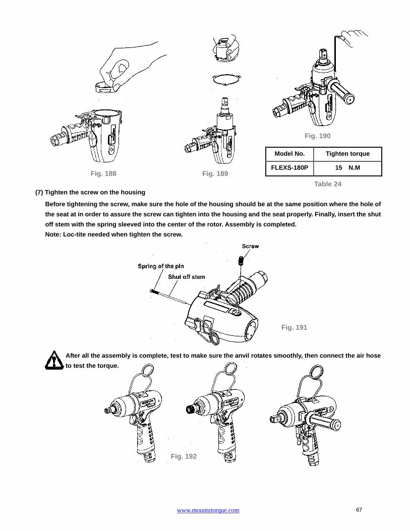
(6) Motor housing, Pulse Unit, and Pulse Unit Housing Assembly
(a) Put the lock washer into the housing. (Fig. 188)
(b) Put the pulse unit, washer, pulse unit housing in order. (Fig. 189)
(c) Lock up the housings with 3 screws, Please refer to Table 12 for the tighten torque of screws.
NOTE : The 3 screws must be applied with loc-tite.
Fig. 185
Fig. 186
Fig. 187
66
www.mountztorque.com
(7) Tighten the screw on the housing
Before tightening the screw, make sure the hole of the housing should be at the same position where the hole of
the seat at in order to assure the screw can tighten into the housing and the seat properly. Finally, insert the shut
off stem with the spring sleeved into the center of the rotor. Assembly is completed.
Note: Loc-tite needed when tighten the screw.
After all the assembly is complete, test to make sure the anvil rotates smoothly, then connect the air hose
to test the torque.
Model No. Tighten torque
FLEXS-180P 15 N.M Fig. 188 Fig. 189
Fig. 190
Table 24
Fig. 191
Fig. 192
67
www.mountztorque.com
General safety rules
For multiple hazards, read and understand the safety instructions before installing,operating, repairing, maintaining, changing accessories on, or working near the powertool. Failure to do so can result in serious bodily injury.
Only qualified and trained operators should install, adjust or use the power tool. Do not modify this power tool. Modifications can reduce the effectiveness of safety
measures and increase the risks to the operator. Do not discard the safety instructions; give them to the operator. Do not use the power tool if it has been damaged. Tools shall be inspected periodically to verify that the ratings and markings are legibly
marked on the tool. The employer/user shall contact the manufacturer to obtainreplacement marking labels when necessary.
Projectile hazards
Be aware that failure of the work piece, of accessories or even of the inserted tool itselfcan generate high-velocity projectiles.
Always wear impact-resistant eye protection during the operation of the power tool. The grade of protection required should be assessed for each use. Ensure that the work piece is securely fixed.
Entanglement hazards
Entanglement hazards can result in choking, scalping and/or lacerations if looseclothing, personal jewellry, neckwear, hair or gloves are not kept away from the tooland accessories.
Gloves can become entangled with the rotating drive, causing severed or brokenfingers.
Rotating drive sockets and drive extensions can easily entangle rubber-coated ormetal-reinforced gloves.
Do not wear loose-fitting gloves or gloves with cut or frayed fingers. Never hold the drive, socket or drive extension. Keep hands away from rotating drives.
MODEL Bolt Capacity Inserted Tools
FLEXS-30PX FLEXS-40PX FLEXS-50PX FLEXS-60PX FLEXS-65PX FLEXS-70PX
M6 M6-M8
M8 M8
M8-M10 M10 Unit : mm
FLEXS-30P ~ FLEXS-70P FLEXS-90P ~ FLEXS-130P
FLEXS-150P & FLEXS-180P
3/8” power sockets 1/2” power sockets 3/4” power sockets
68

www.mountztorque.com
Operating hazards
The use of the tool can expose the operator's hands to hazards including crushing,impacts, cuts, abrasions and heat. Wear suitable gloves to protect hands.
Operators and maintenance personnel shall be physically able to handle the bulk,weight and power of the tool.
Hold the tool correctly; be ready to counteract normal or sudden movements and haveboth hands available.
Maintain a balanced body position and secure footing. In cases where the means to absorb the reaction torque are requested, it is
recommended to use a suspension arm whenever possible. If that is not possible, sidehandles are recommended for straight case and pistol-grip tools. Reaction bars arerecommended for angle nut runners. In any case, it is recommended to use a means toabsorb the reaction torque above 4 Nm for straight tools, above 10 Nm for pistol-griptools, and above 60 Nm for angle nut runners.
Release the start-and-stop device in the case of an interruption of the energy supply. Use only lubricants recommended by the manufacturer. Fingers can be crushed in open-ended crow-foot nut runners. Do not use in confined spaces and beware of crushing hands between tool and
work piece, especially when unscrewing.
Repetitive motions hazards
When using a power tool, the operator can experience discomfort in the hands, arms,shoulders, neck, or other parts of the body.
While using a power tool, the operator should adopt a comfortable posture whilstmaintaining secure footing and avoiding awkward or off-balanced postures. The operator shouldchange posture during extended tasks, which can help avoid discomfort and fatigue.
If the operator experiences symptoms such as persistent or recurring discomfort, pain, throbbing,aching, tingling, numbness, burning sensations or stiffness, these warning signs should not beignored. The operator should tell the employer and consult a
qualified health professional.
Accessory hazards
Disconnect the power tool from the energy supply before changing the inserted tool oraccessory.
Do not touch sockets or accessories during impacting, as this increases the risk ofcuts, burns or vibration injuries.
Use only sizes and types of accessories and consumables that are recommended bythe power tool manufacturer.
Use only impact-wrench-rated sockets in good condition, as poor condition or handsockets and accessories used with impact wrenches can shatter and become aprojectile.
69

www.mountztorque.com
Workplace hazards
Slips, trips and falls are major causes of workplace injury. Be aware of slipperysurfaces caused by the use of the tool and also of trip hazards caused by the air line orhydraulic hose.
Proceed with care in unfamiliar surroundings. Hidden hazards, such as electricity orother utility lines, can exist.
The power tool is not intended for use in potentially explosive atmospheres and is not insulated against coming into contact with electric power. Make sure there are no electrical cables, gas pipes, etc., that can cause a hazard if
damaged by use of the tool.
Dust and fume hazards
Dust and fumes generated when using power tools can cause ill health (for example,cancer, birth defects, asthma and/or dermatitis); risk assessment and implementationof appropriate controls for these hazards are essential.
Risk assessment should include dust created by the use of the tool and the potentialfor disturbing existing dust.
Direct the exhaust so as to minimize disturbance of dust in a dust-filled environment. Where dust or fumes are created, the priority shall be to control them at the point of
emission. All integral features or accessories for the collection, extraction or suppression of
airborne dust or fumes should be correctly used and maintained in accordance withthe manufacturer's instructions.
Use respiratory protection in accordance with employer's instructions and as requiredby occupational health and safety regulations.
Noise hazards
Unprotected exposure to high noise levels can cause permanent, disabling, hearingloss and other problems, such as tinnitus (ringing, buzzing, whistling or humming inthe ears).
Risk assessment and implementation of appropriate controls for these hazards areessential.
Appropriate controls to reduce the risk may include actions such as damping materialsto prevent work pieces from “ringing”.
Use hearing protection in accordance with employer's instructions and as required byoccupational health and safety regulations.
Operate and maintain the power tool as recommended in the instruction handbook, toprevent an unnecessary increase in noise levels.
If the power tool has a silencer, always ensure it is in place and in good working orderwhen the power tool is operating.
Select, maintain and replace the consumable/inserted tool as recommended in theinstruction hand book, to prevent an unnecessary increase in noise.
70

www.mountztorque.com
Vibration hazards
Exposure to vibration can cause disabling damage to the nerves and blood supply ofthe hands and arms.
Keep the hands away from the nut runner sockets. Wear warm clothing when working in cold conditions and keep your hands warm and
dry. If you experience numbness, tingling, pain or whitening of the skin in your fingers or
hands, stop using the power tool, tell your employer and consult a physician. Operate and maintain the power tool as recommended in the instruction handbook, to
prevent an unnecessary increase in vibration levels. Do not use worn or ill-fitting sockets or extensions, as this is likely to cause a
substantial increase in vibration. Select, maintain and replace the consumable/inserted tool as recommended in the instruction handbook, to prevent an unnecessary increase in vibration levels. Sleeve fittings should be used where practicable. Support the weight of the tool in a stand, tensioner or balancer, if possible. Hold the tool with a light but safe grip, taking account of the required hand reaction
forces, because the risk from vibration is generally greater when the grip force is higher.
Additional safety instructions for pneumatic power tool
Air under pressure can cause severe injury Always shut off air supply, drain hose of air pressure and disconnect tool from air
supply when not in use, before changing accessories or when making repairs Never direct air at yourself or anyone else. Whipping hoses can cause severe injury. Always check for damaged or loose hoses
and fittings. Cold air shall be directed away from the hands. Do not use quick-disconnect couplings at tool inlet for impact and air-hydraulic impulse
wrenches. Use hardened steel (or material with comparable shock resistance)threaded hose fittings.
Whenever universal twist couplings (claw couplings) are used, lock pins shall beinstalled and whipcheck safety cables shall be used to safeguard against possiblehose-to-tool and hose-and-hose connection failure.
Do not exceed the maximum air pressure stated on the tool. For torque-control and continuous-rotation tools, the air pressure has a safety critical
effect on performance. Therefore, requirements for length and diameter of the hose shall be specified.
Never carry an air tool by the hose.
71

www.mountztorque.com
Fig. 195
Fig. 193
Fig. 196
Steps for Torque Adjustment – Straight Type
1. Loosen the screw on the pulse unit housing.
2. Rotate the anvil manually; adjust the valve screw inside the pulse unit to the hole; where the screw taken off.
Then, use the attached tool to adjust the torque. Torque increased by turning clockwise and vise versa.
3. Tighten the screw back to the pulse unit housing.
Increase torque
Reduce torque
Fig. 194
72

www.mountztorque.com
DISASSEMBLEY/ASSEMBLEY FOR PULSE TOOLS - FLEX-30S, FLEX-40S, FLEX-50S, FLEX-60S, FLEX-70S, FLEX-80S, FLEX-30SX, FLEX-40SX, FLEX-50SX,
FLEX-60SX, FLEX-70SX
PULSE MECHANISM DISASSEMBLY
(1) Anvil Unit Disassembly: (for Model No. FLEX-30SX, FLEX-40SX, FLEX-50SX, FLEX-60SX , FLEX-70SX)
Press down the hold spacer, and find the anvil collar. Use an acicular piece to get the anvil collar out, then take
the quick change holder, the hold spacer, the spring, and the steel ball apart.
The steel ball may drop off when taking out the Quick Change Holder
(2) Pulse Unit Housing Disassembly:
Fix the tool by a vise, use an adjustable wrench clockwise to loosen the pulse unit housing until the pulse unit
housing detach from the motor housing. Then, take the pulse unit out, Fig. 198.
甲、
Vise
Note: Handle rubber must be covered by a piece of cloth to avoid damage
Fig. 198
Vise
Note: Handle rubber must be covered by a piece of cloth toavoid damage
Fig. 197
73

www.mountztorque.com
Fig.7
Appliance
(3) Pulse Unit Disassembly:
Fix the pulse unit by a vise. Use the appliance (see Table 25) to loosen the lock nut on the pulse unit, Fig. 199.
Note: Lock-tite was applied on the luck nut when tools were assembled.
Put the Appliance, see Table 26 the anvil and tap on it slightly to detach the interior parts from the pulse unit,
Fig.200.
(4) Parts of Pulse Cylinder Unit:
a. FLEX-30S
Appliance No. Apply to
63-40RT001
FLEX-30S, FLEX-30SX, FLEX-40S,
FLEX-40SX, FLEX-50S, FLEX-50SX,
FLEX-60S, FLEX-60SX
63-70RT001 FLEX-70S, FLEX-70SX, FLEX-80S
Appliance No. Apply to
63-40RT002
FLEX-30S, FLEX-30SX, FLEX-40S
FLEX-40SX, FLEX-50S, FLEX-50SX
FLEX-60S, FLEX-60SX, FLEX-70S
FLEX-70SX, FLEX-80S
Fig. 200
Table 26
Table 25 Fig. 199
Lock Nut
Washer
O-RingRear Plate
Block Cap
Pin
Pin
Pulse Cylinder
SpringPressure Valve
O-Ring
O-RingValve
Valve ScrewO-Ring
Back Up Ring
Spring
Drive Blade
Roller
Anvil
Front Plate
Pin
X-Ring
Front CoverSpring Pin
O-RingGreasing Screw
O-Ring
Pulse Cylinder Seat
Appliance
74

www.mountztorque.com
Lock Nut
Washer
O-Ring
Rear Plate
Block CapPulse Cylinder
Pin
PinPin
O-RingValve
Valve ScrewO-Ring
Back Up Ring
SpringPressure Valve
O-RingSpring
Drive BladeRoller
AnvilX-Ring
Back Up Ring
Front Cover
Spring Pin
O-RingGreasing Screw
O-Ring
Pulse Cylinder Seat
b. FLEX-40S, FLEX-50S, FLEX-60S, FLEX-70S
c. FLEX-80S
d. FLEX-30SX
Lock Nut
Washer
O-RingRear PlatePin
Pin
Block CapPulse Cylinder
SpringPressure Valve
O-RingSpring
Drive Blade
Roller
Anvil
Front PlatePin
O-RingValve
Valve ScrewBack Up Ring
X-Ring
Back Up Ring
Front Cover
Spring Pin
O-RingGreasing Screw
O-Ring
Pulse Cylinder Seat
O-Ring
Lock Nut
Washer
O-RingRear PlatePin
Block CapPulse Cylinder
SpringPressure Valve
O-Ring
PinO-Ring
Valve
Valve Screw
O-Ring
Spring
Drive BladeRoller
Steel Ball
AnvilFront PlatePin
X-Ring
Front CoverSpring Pin
O-RingGreasing Screw
O-Ring
Pulse Cylinder Seat
Back Up Ring
75

www.mountztorque.com
Valve Screw
Step 2; Fig. 203
Pin
Small Hole
Big Hole
O-ring
Step 1; Fig. 202
e. FLEX-40SX, FLEX-50SX, FLEX-60SX, FLEX-70SX
PULSE UNIT ASSEMBLY:
(1) Pulse Cylinder Unit Assembly:
Install the pins on both sides of the pulse cylinder. (Fig. 201)
Sleeve the o-ring to the valve and install the valve into the big hole on the pulse cylinder. (Step 1; Fig.202)
Insert the pin into the hole on the side of the pulse cylinder. (Step 2; Fig.203)
Tighten the valve screw left thread to the pressure valve. (Step 3; Fig.203)
NOTE: the valve screw MUST tighten to the most bottom position certainly.
Plug the spring into the hole then install the pressure valve that with the o-ring sleeved.
(Step 4; Fig. 204)
Pressure Valve
Spring
Step 4; Fig. 204
Lock Nut
Washer
O-RingRear Plate
Pin
Pin
Block CapPulse Cylinder
SpringPressure ValveO-Ring
Spring
Drive BladeRoller
Steel Ball
AnvilFront PlatePin
O-RingValve
Valve Screw
O-Ring
Back Up Ring
X-RingFront Cover
Spring Pin
O-RingGreasing Screw
O-Ring
Pulse Cylinder Seat
Back Up Ring
Pin
Pin
Pulse CylinderFig. 201
76

www.mountztorque.com
Step 5; Fig. 205
(d) Fig. 212
Front Plate
Corresponding position
Fig. 208
Front Plate
Install the front plate and make sure the corresponding position with the pins. (Step 5; Fig.205)
(2) Anvil Unit Assembly:
Install the roller to the drive blade, then insert the springs into the anvil and press the blades from both sides.
Finally put the anvil to the pulse cylinder to complete the anvil unit assembly.
MUST follow the direction as shown in Figure 208 while installing the anvil unit into the pulse cylinder; be sure
to aim at the highest points by two sides of the interior pulse unit and press the two drive blades in slowly.
(3) Front Cover and Rear Plate of Pulse Cylinder Assembly
FLEX-30S, FLEX-30SX
(a) Put the O-ring on the Rear Plate and install the rear plate to the pulse cylinder, Be sure the positions of the
pin and the hole are corresponded. (Fig. 209)
(b) Put the X-ring on the anvil with the oil applied. (Fig. 210)
(c) Put the Back up ring and O-ring into the Valve Screw. (Fig. 211)
(d) Install the front cover to the pulse cylinder by the corresponding positions. (Fig. 212)
Fig. 207
Press
Press
Fig. 206
Roller
Drive Blade
(a) Fig. 209
O-ring
Rear Plate
Spring
(c) Fig. 211
Back Up Ring
O-ring
Corresponding position
Front Cover
(b) Fig. 210
X-ring
77

www.mountztorque.com
After installing the front cover, put the o-ring on the greasing screw, then tighten the greasing screw but
release it a little bit after completely tightened.
FLEX-40S, FLEX-40SX, FLEX-50S, FLEX-50SX, FLEX-60S, FLEX-60SX, FLEX-70S, FLEX-70SX
(a) Put the O-ring on the Rear Plate and install the rear plate to the pulse cylinder, Be sure the positions of the
pin and the hole are corresponded. (Fig. 214)
(b) Put the X-ring and back up ring on the anvil with the oil applied. (Fig. 215)
(c) Put the Back up ring and O-ring into the Valve Screw. (Fig. 216)
(d) Install the front cover to the pulse cylinder by the corresponding positions. (Fig. 217)
After installing the front cover, put the o-ring on the greasing screw, then tighten the greasing screw but
release it a little bit after completely tightened.
FLEX-80S
(a) Put the O-ring on the Rear Plate and install the rear plate to the pulse cylinder, Be sure the positions of the
pin and the hole are corresponded. (Fig. 219)
(b) Put the X-ring and back up ring on the anvil with the oil applied. (Fig. 220)
(c) Put the Back up ring and O-ring into the Valve Screw. (Fig. 221)
(d) Install the front plate to the pulse cylinder by the corresponding positions. (Fig. 222)
(a) Fig. 214 (d) Fig. 217 (b) Fig. 215
Back Up Ring
X-ring
O-ring
Rear Plate
Corresponding position
Greasing Screw
O-ring Fig. 213
Front Cover
(c) Fig. 216
O-ring
Back Up Ring
Fig. 218
O-ring
Greasing Screw
78

www.mountztorque.com
Fig. 224
Half-circle gaps
Pin
O-ring
Fig. 225
Pulse Cylinder Seat
Greasing Screw
After installing the front cover, put the o-ring on the greasing screw, then tighten the greasing screw but
release it a little bit after completely tightened.
(4) Pulse Cylinder Seat and Lock Nut of Pulse Cylinder Assembly
Place the o-ring inside the bottom of the pulse cylinder seat, then combine the
pulse cylinder seat with the assembled pulse cylinder unit. (Fig. 224, Fig. 225)
Make sure the half-circle gaps aim at the corresponding positions.
Use the appliance to push out the rear plate from the pulse cylinder seat. See Table 26 in reference to the proper
appliance selection. (Fig. 226)
Fill up the interior pulse cylinder with the pulse oil about 90% full by an injector. (Fig. 227)
Install the rear plate taken from the step 2 on the pulse cylinder. Note the corresponding positions!
Turn the assembled unit up side down so the rear plate is at the bottom. Then press the pulse cylinder seat all
the way down to the fixed position. Make sure the corresponding positions are matched exactly.
O-ring
Pulse Cylinder Seat
(a) Fig. 219
O-ring
Rear Plate
Back Up Ring
X-ring
(b) Fig. 220 (c) Fig. 221 (d) Fig. 222
Back Up Ring O-ring
Front Plate
Corresponding position
Fig. 223
O-ring
Greasing Screw
79

www.mountztorque.com
Fig. 231
Fix the pulse cylinder seat by a vise. Use an appliance and a torque wrench, and then turn clockwise to tighten
the lock nut of the pulse cylinder. See Table 27 and 28 in reference to the proper appliance and tightness. (Note:
Lock-tite needed when tightening the lock nut of the pulse cylinder)
After completing the above steps, test to make sure the
square drive of the anvil rotates smoothly.
Appliance No. Apply to
63-40RT001 FLEX-30S, FLEX-30SX, FLEX-40S, FLEX-40SX,
FLEX-50S, FLEX-50SX, FLEX-60S, FLEX-60SX
63-70RT001 FLEX-70S, FLEX-70SX, FLEX-80S
Model No. Tighten torque
FLEX-30S 70 N.M
FLEX-30SX 70 N.M
FLEX-40S 80 N.M
FLEX-40SX 80 N.M
FLEX-50S 80 N.M
FLEX-50SX 80 N.M
Model No. Tighten torque
FLEX-60S 80 N.M
FLEX-60SX 80 N.M
FLEX-70S 100 N.M
FLEX-70SX 100 N.M
FLEX-80S 100 N.M
Table 27
Table 28
Fig. 227 Fig. 228 Fig. 229
Appliance
Fig. 230 Fixed by a vise
Rear Plate
Fig. 226
Appliance
Rear Plate
80

www.mountztorque.com
Fig. 232
Fig. 233
(5) Steps for Pulse Cylinder Oiling:
Loosen the greasing screw, and fill in the authorized oil by
an injector until it is full and overflow.
Take the unit and dip it in an oil tank, then rotate the anvil by a wrench to release air inside, in the mean
time, the unit would be full with oil completely.
Use the screwdriver either, the slotted to tighten the greasing screw, Fig. 234.
Use an air spray gun to blow off the oil on the cylinder seat, Fig. 235.
Loosen the greasing screw again and use an
injector to draw out a little amount of oil ( see Table
29) . Finally, tighten the greasing screw back
to the pulse cylinder unit, Fig. 236.
Fig. 234
Fig. 235
Fig. 236
O-ring
Greasing Screw Slotted
81

www.mountztorque.com
(6) Torque Testing:
Put the washer on the front end of the anvil, and then put another washer on the rear plate.
Tighten the clutch housing by hands.
Test the forward torque by a digital torque tester and make sure the tool pulses smoothly.
Model No. Amount of oil draw
FLEX-30S 0.25 CC
FLEX-30SX 0.25 CC
FLEX-40S 0.3 CC
FLEX-40SX 0.3 CC
FLEX-50S 0.35 CC
FLEX-50SX 0.35 CC
Model No. Amount of oil draw
FLEX-60S 0.45 CC
FLEX-60SX 0.45 CC
FLEX-70S 0.63 CC
FLEX-70SX 0.63 CC
FLEX-80S 0.6 CC
Table 29
Digital Torque Tester
Wrench seriesDriver series
Fig. 238
Fig. 237
Washer
Anvil
Washer
Rear plate
Fig. 239
82

www.mountztorque.com
If the test result is NG (see Table 30 in reference to the torque standard), MUST draw out or add a little
amount of oil and do the following steps:
Loosen the pulse unit housing by hands.
Loosen the greasing screw.
Draw out or add a little amount of oil.
Tighten the greasing screw back.
Tighten the pulse unit housing.
Test the torque again. If the test result is still NG, repeat the Steps ~until the standard torque
is reached.
(7) Pulse Unit Housing Assembly:
Fix the housing by a vise. Turn the wrench in counter clockwise direction to tighten the pulse unit housing.
(8) Anvil Unit Assembly: (for FLEX-30SX, FLEX-40SX, FLEX-50SX, FLEX-60SX and FLEX-70SX)
(a) Place the steel ball, the quick change holder, the spring, and the hold spacer orderly on the anvil as shown.
(b) Put the anvil collar on the Anvil. (Fig. 242)
Model No. Air inlet pressure 0.6 Mpa
N.M (at least)
FLEX-30S 12.5
FLEX-30SX 11.5
FLEX-40S 19
FLEX-40SX 17
FLEX-50S 27
FLEX-50SX 25
FLEX-60S 35
FLEX-60SX 30
FLEX-70S 47
FLEX-70SX 40
FLEX-80S 70
Table 30
Note: Handle rubber must be covered by a piece of cloth to avoid damage
Fig. 240
83

www.mountztorque.com
HOUSING AND MOTOR SET DISASSEMBLY:
(1) Cylinder Unit Disassembly:
Take a piece of cloth to cover the housing handle and fix the tool with a vise. Use the appliance (see Table
31)
to take the lock nut out of cylinder by turning clockwise.
Use a wrench to loosen the screw on the side of the motor housing and detach the parts of the regulator.
Appliance No. Apply to
63-40RT004 FLEX-30S, FLEX-30SX, FLEX-40S, FLEX-40SX
FLEX-50S, FLEX-50SX, FLEX-60S, FLEX-60SX
63-70SRT001 FLEX-70S, FLEX-70SX
63-70XRT004 FLEX-80S
Fig. 243 Lock nut of Cylinder
Table 31
Fig. 241
Appliance
Note: Handle rubber must be covered by a piece of cloth to avoid damage
Fig. 242
Anvil Collar
Hex- hole of Anvil
Hold
Spring
Quick Change Holder
Steel Ball Anvil
Screw
Regulator
Fig. 244
84

www.mountztorque.com
Spring
Air Inlet
Muffler
Exhaust Deflector
Snap Ring
O-ring
Valve Stem
Bushing
Take a piece of cloth and lay it on a table before disassembly. Hold the housing downward to detach the
cylinder unit out.
Parts of Motor Set:
The rotor and the rear end plate must be press fitted. The clearance of the two parts must be in between
0.01~ 0.02 mm. It would not be easy to assemble the two parts by repair centers in general. Therefore, as
there is a need of repair on the parts of the rotor, the rear end plate, and the ball bearing, we strongly
suggest replacing a complete ROTOR UNIT, which is including the rotor, the rear plate, and the ball bearing.
The rotor unit would be full assembled and well-measured before delivery.
(2) Air Inlet Disassembly:
Take off the snap ring from the air inlet, and then take off the exhaust deflector. Use an open wrench to open
the air inlet in counter clock wise direction. All the interior parts are detached.
Fig. 245
Fig. 246
Fig. 247 85

www.mountztorque.com
(3) Trigger Set Disassembly:
Remove the spring pin from the trigger to detach the interior parts. And then, remove the housing rubber and
the hanger to complete the disassembly.
HOUSING AND MOTOR SET ASSEMBLY:
(1) Cylinder Unit Assembly
Place the rotor blades into the rotor. Insert the spring pin
A and B into the cylinder. Make sure the pins aim at the
pin holes when putting the cylinder down.
Make the groove of the air inlet plate toward the rear plate and assemble. Make sure the holes aim at the
pin while assembling, Fig. 251.
Assemble the regulator with the rotor- air inlet unit. Make sure the steel balls of the regulator are placed
on the holes of the air inlet plate. Then, place the seat with the o-ring sleeved on the regulator. Assembly
is completed.
Apply the lubricator between parts while assembling.
Seat
O-ring
Fig. 262
Fig. 248
Fig. 253
Regulator
Seat
Holes
O-ring
Steel Balls
O-ring
Grooves
Fig. 252
Fig. 250 Rotor unit
Spring A
Spring B
Trigger
Pin
Spring Pin
Fig. 249
Housing
Hanger
Housing Rubber
Spring Pin
Fig. 251
Air Inlet Plate
Rear Plate
86

www.mountztorque.com
Spring pin
Screw of F/R valve
Hole inside the housing
Motor set unit
(2) Housing, Motor set unit and Lock Nut of Cylinder Assembly:
Put the housing rubber on the housing.
Install the motor set into the housing. Make sure the direction is correct, i.e. the spring pin on the side of
the cylinder aims at the hole inside the housing.
Have the hole on the regulator aim at the screw hole on the side of the F/R valve and make sure the screw
is tightened into the regulator and the F/R valve.
Fix the tool by a vise. Place the lock nut of the cylinder nut and tighten by the appliance in counter clockwise
direction to complete the assembly. See the Table 32 and 33 in reference to appliance use and tighten torque.
Model No. Tighten torque
FLEX-30S 40 N.M
FLEX-30SX 40 N.M
FLEX-40S 40 N.M
FLEX-40SX 40 N.M
FLEX-50S 40 N.M
FLEX-50SX 40 N.M
FLEX-60S 40 N.M
FLEX-60SX 40 N.M
FLEX-70S 40 N.M
FLEX-70SX 40 N.M
FLEX-80S 40 N.M
Appliance No. Apply to
63-40RT004
FLEX-30S, FLEX-30SX, FLEX-40S,
FLEX-40SX, FLEX-50S, FLEX-50SX,
FLEX-60S, FLEX-60SX
63-70SRT001 FLEX-70S, FLEX-70SX
63-70XRT004 FLEX-80S
Table 32
Table 33
Fig. 254
Screw
Screw of F/R valve
Regulator
Fig. 255
Fig. 256
Appliance
Note: Handle rubber must be covered by a piece of cloth to avoid damage
87

www.mountztorque.com
Fig. 268
Driver series
Fig. 259
Wrench series
Valve StemSpring
Muffler
Exhaust Deflector
Air Inlet
Snap Ring
O-ring
Bushing
Spring Pin
Trigger
Spring Pin
Hanger
Fig. 258
(3) Housing and Air Inlet Assembly:
Install and tighten the parts of air inlet one by one and in order. (NOTE: Apply the Lock-tite on the threads of air
inlet before assembly)
(4) Housing and Trigger Set Assembly:
Install the parts of the trigger set orderly (see Fig. 258
drawing for reference). Then, Insert the spring pins to
fix all the parts. And, install the hanger to complete
the assembly.
After all the assembly is complete, test to make sure the anvil rotates smoothly, then connect the air
hose to test the torque.
Fig. 257
88

www.mountztorque.com
MODEL Bolt Capacity Inserted Tools
FLEX-30SX FLEX-40SX FLEX-50SX FLEX-60SX FLEX-70SX
M6 M6-M8
M8 M8
M8-M10 Unit : mm
FLEX-30S ~ FLEX-70S 3/8” power sockets
General safety rules
For multiple hazards, read and understand the safety instructions before installing,operating, repairing, maintaining, changing accessories on, or working near the powertool. Failure to do so can result in serious bodily injury.
Only qualified and trained operators should install, adjust or use the power tool. Do not modify this power tool. Modifications can reduce the effectiveness of safety
measures and increase the risks to the operator. Do not discard the safety instructions; give them to the operator. Do not use the power tool if it has been damaged. Tools shall be inspected periodically to verify that the ratings and markings are legibly
marked on the tool. The employer/user shall contact the manufacturer to obtainreplacement marking labels when necessary.
Projectile hazards
Be aware that failure of the work piece, of accessories or even of the inserted tool itselfcan generate high-velocity projectiles.
Always wear impact-resistant eye protection during the operation of the power tool. The grade of protection required should be assessed for each use. Ensure that the work piece is securely fixed.
Entanglement hazards
Entanglement hazards can result in choking, scalping and/or lacerations if looseclothing, personal jewelry, neck ware, hair or gloves are not kept away from the tooland accessories.
Gloves can become entangled with the rotating drive, causing severed or brokenfingers.
Rotating drive sockets and drive extensions can easily entangle rubber-coated ormetal-reinforced gloves.
Do not wear loose-fitting gloves or gloves with cut or frayed fingers. Never hold the drive, socket or drive extension. Keep hands away from rotating drives.
Operating hazards
The use of the tool can expose the operator's hands to hazards including crushing,impacts, cuts, abrasions and heat. Wear suitable gloves to protect hands.
89

www.mountztorque.com
Operators and maintenance personnel shall be physically able to handle the bulk,weight and power of the tool.
Hold the tool correctly; be ready to counteract normal or sudden movements and haveboth hands available.
Maintain a balanced body position and secure footing. In cases where the means to absorb the reaction torque are requested, it is
recommended to use a suspension arm whenever possible. If that is not possible, sidehandles are recommended for straight case and pistol-grip tools. Reaction bars arerecommended for angle nut runners. In any case, it is recommended to use a means toabsorb the reaction torque above 4 Nm for straight tools, above 10 Nm for pistol-griptools, and above 60 Nm for angle nut runners.
Release the start-and-stop device in the case of an interruption of the energy supply. Use only lubricants recommended by the manufacturer. Fingers can be crushed in open-ended crow-foot nut runners. Do not use in confined spaces and beware of crushing hands between tool and
work piece, especially when unscrewing.
Repetitive motions hazards
When using a power tool, the operator can experience discomfort in the hands, arms,shoulders, neck, or other parts of the body.
While using a power tool, the operator should adopt a comfortable posture whilstmaintaining secure footing and avoiding awkward or off-balanced postures. The operator shouldchange posture during extended tasks, which can help avoid discomfort and fatigue.
If the operator experiences symptoms such as persistent or recurring discomfort, pain, throbbing,aching, tingling, numbness, burning sensations or stiffness, these warning signs should not beignored. The operator should tell the employer and consult a
qualified health professional.
Accessory hazards
Disconnect the power tool from the energy supply before changing the inserted tool oraccessory.
Do not touch sockets or accessories during impacting, as this increases the risk ofcuts, burns or vibration injuries.
Use only sizes and types of accessories and consumables that are recommended bythe power tool manufacturer.
Use only impact-wrench-rated sockets in good condition, as poor condition or handsockets and accessories used with impact wrenches can shatter and become aprojectile.
Workplace hazards
Slips, trips and falls are major causes of workplace injury. Be aware of slipperysurfaces caused by the use of the tool and also of trip hazards caused by the air line orhydraulic hose.
90

www.mountztorque.com
Proceed with care in unfamiliar surroundings. Hidden hazards, such as electricity orother utility lines, can exist.
The power tool is not intended for use in potentially explosive atmospheres and is not insulated against coming into contact with electric power. Make sure there are no electrical cables, gas pipes, etc., that can cause a hazard if
damaged by use of the tool.
Dust and fume hazards
Dust and fumes generated when using power tools can cause ill health (for example,cancer, birth defects, asthma and/or dermatitis); risk assessment and implementationof appropriate controls for these hazards are essential.
Risk assessment should include dust created by the use of the tool and the potentialfor disturbing existing dust.
Direct the exhaust so as to minimize disturbance of dust in a dust-filled environment. Where dust or fumes are created, the priority shall be to control them at the point of
emission. All integral features or accessories for the collection, extraction or suppression of
airborne dust or fumes should be correctly used and maintained in accordance withthe manufacturer's instructions.
Use respiratory protection in accordance with employer's instructions and as requiredby occupational health and safety regulations.
Noise hazards
Unprotected exposure to high noise levels can cause permanent, disabling, hearingloss and other problems, such as tinnitus (ringing, buzzing, whistling or humming inthe ears).
Risk assessment and implementation of appropriate controls for these hazards areessential.
Appropriate controls to reduce the risk may include actions such as damping materialsto prevent work pieces from “ringing”.
Use hearing protection in accordance with employer's instructions and as required byoccupational health and safety regulations.
Operate and maintain the power tool as recommended in the instruction handbook, toprevent an unnecessary increase in noise levels.
If the power tool has a silencer, always ensure it is in place and in good working orderwhen the power tool is operating.
Select, maintain and replace the consumable/inserted tool as recommended in theinstruction hand book, to prevent an unnecessary increase in noise.
Vibration hazards
Exposure to vibration can cause disabling damage to the nerves and blood supply ofthe hands and arms.
Keep the hands away from the nut runner sockets. Wear warm clothing when working in cold conditions and keep your hands warm and
91

www.mountztorque.com
dry. If you experience numbness, tingling, pain or whitening of the skin in your fingers or hands, stop using the power tool, tell your employer and consult a physician. Operate and maintain the power tool as recommended in the instruction handbook, to prevent an unnecessary increase in vibration levels. Do not use worn or ill-fitting sockets or extensions, as this is likely to cause a substantial increase in vibration. Select, maintain and replace the consumable/inserted tool as recommended in the instruction handbook, to prevent an unnecessary increase in vibration levels. Sleeve fittings should be used where practicable. Support the weight of the tool in a stand, tensioner or balancer, if possible. Hold the tool with a light but safe grip, taking account of the required hand reaction forces, because the risk from vibration is generally greater when the grip force is higher.
Additional safety instructions for pneumatic power tool
Air under pressure can cause severe injury
Always shut off air supply, drain hose of air pressure and disconnect tool from air supply when not in use, before changing accessories or when making repairs
Never direct air at yourself or anyone else. Whipping hoses can cause severe injury. Always check for damaged or loose hoses
and fittings. Cold air shall be directed away from the hands. Do not use quick-disconnect couplings at tool inlet for impact and air-hydraulic impulse
wrenches. Use hardened steel (or material with comparable shock resistance) threaded hose fittings.
Whenever universal twist couplings (claw couplings) are used, lock pins shall be installed and whipcheck safety cables shall be used to safeguard against possible hose-to-tool and hose-and-hose connection failure.
Do not exceed the maximum air pressure stated on the tool. For torque-control and continuous-rotation tools, the air pressure has a safety critical effect on performance. Therefore, requirements for length and diameter of the hose shall be specified. Never carry an air tool by the hose.
92

www.mountztorque.com
DISASSEMBLEY/ASSEMBLEY FOR PULSE TOOLS - FLEXS-30S, FLEXS-40S, FLEXS-50S, FLEXS-60S, FLEXS-70S, FLEXS-80S, FLEXS-30SX, FLEXS-40SX,
FLEXS-50SX, FLEXS-60SX, FLEXS-70SX
IMPULSE MECHANISM DISASSEMBLY
(1) Anvil Unit Disassembly: (for Model No. FLEXS-30SX, FLEXS-40SX, FLEXS-50SX, FLEXS-60SX, FLEX-70SX)
Press down the hold spacer, and find the anvil collar. Use an acicular piece to get the anvil collar out, then take
the quick change holder, the hold spacer, the spring, and the steel ball apart.
The steel ball may drop off when taking out the Quick Change Holder
(2) Pulse Unit Housing Disassembly:
Fix the tool by a vise, use an adjustable wrench clockwise to loosen the pulse unit housing until the pulse unit
housing detach from the motor housing. Then, take the pulse unit out, Fig 261
Vise
Note: Handle rubber must be covered by a piece of cloth to avoid damage
Note: Handle rubber must be covered by a piece of cloth to avoid damage
Fig. 261
Vise
Fig. 260
93

www.mountztorque.com
Lock Nut
Pressure Valve
O-Ring
Washer
Rear Plate
O-Ring
Block Cap
Pin
PinSpring
Pressure ValveO-Ring
Pulse Cylinder
PinSpring
Steel Ball
O-RingValve
Valve Screw
O-RingBack Up Ring
Block Valve
Spring
Drive Blade
Roller
Anvil
X-Ring
Front Cover
Front Plate
Spring Pin
Greasing ScrewO-Ring
O-Ring
Pulse Cylinder Seat
Fig.7
Appliance
(3) Pulse Unit Disassembly:
Fix the pulse unit by a vise. Use the appliance (see Table 34) to loosen the lock nut on the pulse unit, Fig.
262
Note: Lock-tite was applied on the luck nut when tools were assembled.
Put the Appliance, see Table 35, on the anvil and tap on it slightly to detach the interior parts from the pulse
unit, Fig. 263
Parts of Pulse Cylinder Unit:
a. FLEXS-30S
Appliance No. Apply to
63-40RT001
FLEXS-30S, FLEXS-30SX, FLEXS-40S,
FLEXS-40SX, FLEXS-50S, FLEXS-50SX,
FLEXS-60S, FLEXS-60SX
63-70RT001 FLEXS-70S, FLEXS-70SX, FLEXS-80S
Appliance No. Apply to
63-40RT002
FLEXS-30S, FLEXS-30SX, FLEXS-40S
FLEXS-40SX, FLEXS-50S, FLEXS-50SX
FLEXS-60S, FLEXS-60SX, FLEXS-70S
FLEXS-70SX, FLEXS-80S
Fig. 263 Table 35
Table 34
Fig. 262
Appliance
94

www.mountztorque.com
Pressure Valve
O-Ring
Washer
Rear Plate
O-RingPin
Block Cap
Pulse CylinderPin
PinSpring
Pressure ValveO-Ring
SpringSteel Ball
O-RingValve
Valve ScrewO-Ring
Back Up Ring
Block Valve
Spring
Drive BladeRoller
Anvil
X-Ring
Back Up Ring
Front CoverSpring Pin
Greasing ScrewO-Ring
O-Ring
Pulse Cylinder Seat
Lock Nut
b. FLEXS-40S, FLEXS-50S, FLEXS-60S, FLEXS-70S
c. FLEXS-80S
d. FLEXS-30SX
Lock Nut
Pressure Valve
O-Ring
WasherRear Plate
O-Ring
Block Cap
Pin
Pulse CylinderPin
Spring
Pressure ValveO-Ring
PinSpring
Steel Ball
O-RingValve
Valve Screw
O-RingBlock Valve
Spring
Drive Blade
Roller
AnvilFront Plate
X-RingBack Up Ring
Front Cover
Spring Pin
Greasing ScrewO-Ring
O-Ring
Pulse Cylinder Seat
Back Up Ring
Lock Nut
Pressure Valve
O-Ring
Washer
Rear Plate
O-Ring
Block Cap
Pin
Pulse CylinderPin
Spring
Pressure ValveO-Ring
PinSpring
Steel BallO-Ring
ValveValve Screw
O-RingBlock ValveSpring
Drive Blade
AnvilSteel Ball
Roller
Front Plate
X-Ring
Front Cover
Greasing ScrewO-Ring
Spring PinO-Ring
Pulse Cylinder Seat
Back Up Ring
95

www.mountztorque.com
Small Hole
Big Hole
O-ring
Step 1; Fig. 265
e. FLEXS-40SX, FLEXS-50SX, FLEXS-60SX, FLEXS-70SX
PULSE UNIT ASSEMBLY:
(1) Pulse Cylinder Unit Assembly:
Install the pins on both sides of the pulse cylinder. (Fig. 264)
Sleeve the o-ring to the valve and install the valve into the big hole on the pulse cylinder. (Step 1; Fig.265)
Insert the pin into the hole on the side of the pulse cylinder. (Step 2; Fig.266)
Tighten the valve screw left thread to the pressure valve. (Step 3; Fig.266)
NOTE: the valve screw MUST tighten to the most bottom position certainly.
Lock Nut
Pressure Valve
O-Ring
Washer
Rear Plate
O-RingBlock Cap
Pin
Pulse Cylinder
Pin
Spring
Pressure ValveO-Ring
Pin
Spring
Steel Ball
O-RingValve
Valve Screw
O-Ring
Block Valve
Spring
AnvilSteel Ball
Drive BladeRoller
Front PlateX-Ring
Back Up RingFront Cover
Spring Pin
Greasing ScrewO-Ring
O-Ring
Pulse Cylinder Seat
Back Up Ring
Pin
Pin
Pulse CylinderFig. 264
Valve Screw
Step 2; Fig. 266
Pin
96

www.mountztorque.com
Fig. 271
Front Plate
Step 5; Fig. 268 Front Plate
Put the spring into the hole then install the pressure valve that with the o-ring sleeved. (Step 4; Fig.267)
Install the front plate and make sure the corresponding position with the pins. (Step 5; Fig.268)
(2) Anvil Unit Assembly:
Install the roller to the drive blade, then insert the springs into the anvil and press the blades from both sides.
Finally put the anvil to the pulse cylinder to complete the anvil unit assembly.
MUST follow the direction as shown in Figure 271 while installing the anvil unit into the pulse cylinder; be
sure to aim at the highest points by two sides of the interior pulse unit and press the two drive blades in
slowly.
(3) Front Cover and Rear Plate of Pulse Cylinder Assembly
FLEXS-30S, FLEXS-30SX
(a) Put the O-ring on the Rear Plate and install the rear plate to the pulse cylinder, Be sure the positions of
the pin and the hole are corresponded. (Fig. 272) Then, plug the pressure valve with the convex facing
outside in the hole on the rear plate.
(b) Put the X-ring on the anvil with the oil applied. (Fig. 273)
(c) Put the Back up ring and O-ring into the Valve Screw.(Fig. 274)
(d) Install the front cover to the pulse cylinder by the corresponding positions. (Fig. 275)
Fig. 270
Press
Press
Fig. 269
Roller
Drive Blade
Spring
Corresponding position
Pressure Valve
Spring
Step 4; Fig. 267
97

www.mountztorque.com
(d) Fig. 280
(d) Fig. 275
After installing the front cover, put the o-ring on the greasing screw, then tighten the greasing screw but
release it a little bit after completely tightened.
FLEXS-40S, FLEXS-40SX, FLEXS-50S, FLEXS-50SX, FLEXS-60S, FLEXS-60SX, FLEXS-70S, FLEXS-70SX
(a) Put the O-ring on the Rear Plate and install the rear plate to the pulse cylinder, Be sure the positions of
the pin and the hole are corresponded. (Fig. 277) Then, plug the pressure valve with the convex facing
outside in the hole on the rear plate.
(b) Put the X-ring and back up ring on the anvil with the oil applied. (Fig. 278)
(c) Put the Back up ring and O-ring into the Valve Screw. (Fig. 279)
(d) Install the front cover to the pulse cylinder by the corresponding positions. (Fig. 280)
After installing the front cover, put the o-ring on the greasing screw, then tighten the greasing screw but
release it a little bit after completely tightened.
Pressure Valve O-ring
O-ring
Rear Plate
(a) Fig. 272
Corresponding position
Pressure ValveO-ring
O-ring
Rear Plate
Back Up Ring
X-ring Corresponding position
Front Cover
(a) Fig. 277 (b) Fig. 278
Fig. 281
O-ring
Back Up Ring
(c) Fig. 274
Front Cover
O-ring
Back Up Ring
(c) Fig. 279
(b) Fig. 273
X-ring
Greasing Screw O-ring Fig. 276
O-ring Greasing Screw
98

www.mountztorque.com
Half-circle gaps
Pin
O-ringFig. 288
Pulse Cylinder Seat
Greasing Screw
FLEXS-80S
(a) Put the O-ring on the Rear Plate and install the rear plate to the pulse cylinder, Be sure the positions of
the pin and the hole are corresponded. (Fig. 282) Then, plug the pressure valve with the convex facing
outside in the hole on the rear plate.
(b) Put the X-ring and Back up ring on the anvil with the oil applied. (Fig. 283)
(c) Put the Back up ring and O-ring into the Valve Screw. (Fig. 284)
(d) Install the front plate to the pulse cylinder by the corresponding positions. (Fig. 285)
After installing the front cover, put the o-ring on the greasing screw, then tighten the greasing screw but
release it a little bit after completely tightened.
(4) Pulse Cylinder Seat and Lock Nut of Pulse Cylinder Assembly
Place the o-ring inside the bottom of the pulse cylinder seat,
then combine the pulse cylinder seat with the assembled pulse
cylinder unit. (Fig. 287, Fig. 288)
Make sure the half-circle gaps aim at the corresponding positions.
O-ring
Pulse Cylinder Seat
Fig. 287
Pressure Valve O-ring
O-ring
Rear Plate
X-ring
Front Cover
(a) Fig. 282 (b) Fig. 283 (c) Fig. 284 (d) Fig. 285
Back Up Ring
Corresponding position
Back Up Ring O-ring
Fig. 286
O-ring
Greasing Screw
99

www.mountztorque.com
Use the appliance to push out the rear plate from the pulse cylinder seat. See Table 35 in reference to the
proper appliance selection. (Fig. 289)
Fill up the interior pulse cylinder with the pulse oil about 90% full by an injector. Put the steel ball and the
valve spring into the hole on the pulse cylinder in order. (Fig. 290)
Put the block valve into the rear plate taken out at Step 2, and then install the rear plate to the pulse
cylinder.
Make sure the positions of the pins and the holes are exactly matched. (Fig. 291)
Turn the assembled unit up side down so the rear plate is at the bottom. Then press the pulse cylinder seat
all the way down to the fixed position. Make sure the corresponding positions are matched exactly.
Fix the pulse cylinder seat by a vise. Use an appliance and a torque wrench, and then turn clockwise to
tighten the lock nut of the pulse cylinder. See Table 36 and 37 in reference to the proper appliance and
tightness. (Note: Lock-tite needed when tightening the lock nut of the pulse cylinder)
Appliance No. Apply to
63-40RT001
FLEXS-30S, FLEXS-30SX, FLEXS-40S,
FLEXS-40SX,FLEXS-50S, FLEXS-50SX, FLEXS-60S, FLEXS-60SX
63-70RT001 FLEXS-70S, FLEXS-70SX, FLEXS-80S
Fig. 290
Rear Plate
Fig. 291
Block Valve
Fig. 292
Valve Spring
Steel Ball
Appliance
Fig. 293Fixed by a vise
Fig. 289
Appliance
Rear Plate
100
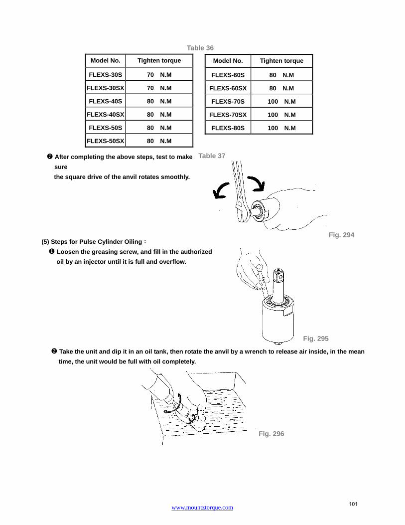
www.mountztorque.com
Fig. 294
Fig. 295
Fig. 296
After completing the above steps, test to make
sure
the square drive of the anvil rotates smoothly.
(5) Steps for Pulse Cylinder Oiling:
Loosen the greasing screw, and fill in the authorized
oil by an injector until it is full and overflow.
Take the unit and dip it in an oil tank, then rotate the anvil by a wrench to release air inside, in the mean
time, the unit would be full with oil completely.
Model No. Tighten torque
FLEXS-30S 70 N.M
FLEXS-30SX 70 N.M
FLEXS-40S 80 N.M
FLEXS-40SX 80 N.M
FLEXS-50S 80 N.M
FLEXS-50SX 80 N.M
Model No. Tighten torque
FLEXS-60S 80 N.M
FLEXS-60SX 80 N.M
FLEXS-70S 100 N.M
FLEXS-70SX 100 N.M
FLEXS-80S 100 N.M
Table 36
Table 37
101

www.mountztorque.com
Use the screwdriver either,the slotted to tighten the greasing screw, Fig. 297.
Use an air spray gun to blow off the oil on the cylinder seat, Fig. 298.
Loosen the greasing screw again and use an
injector to draw out a little amount of oil ( see Table
38) . Finally, tighten the greasing screw back to the
pulse cylinder unit, Fig. 299.
Model No. Amount of oil draw
FLEXS-30S 0.2 CC
FLEXS-30SX 0.2 CC
FLEXS-40S 0.25 CC
FLEXS-40SX 0.25 CC
FLEXS-50S 0.3 CC
FLEXS-50SX 0.3 CC
Model No. Amount of oil draw
FLEXS-60S 0.4 CC
FLEXS-60SX 0.4 CC
FLEXS-70S 0.6 CC
FLEXS-70SX 0.6 CC
FLEXS-80S 0.56 CC
Fig. 297
Fig. 298
Fig. 299
Table 38
O-ring
Greasing Screw Slotted
102

www.mountztorque.com
(6) Torque Testing:
Put the washer on the front end of the anvil, and then put another washer on the rear plate.
Tighten the clutch housing by hands.
Test the forward torque by a digital torque tester and make sure the tool pulses smoothly.
Washer
Anvil
Washer
Rear Plate
Fig. 300
Fig. 302
Digital Torque Tester
Wrench seriesDriver series
Fig. 301
103

www.mountztorque.com
Note: Handle rubber must be covered by a piece of cloth to avoid damage
If the test result is NG (see Table 39 in reference to the torque standard), MUST draw out or add a little
amount of oil and do the following steps:
Loosen the pulse unit housing by hands.
Loosen the greasing screw.
Draw out or add a little amount of oil.
Tighten the greasing screw back.
Tighten the pulse unit housing.
Test the torque again. If the test result is still NG, repeat the Steps ~until the standard torque
is reached.
(7) Pulse Unit Housing Assembly:
Fix the housing by a vise. Turn the wrench in counter clockwise direction to tighten the pulse unit housing.
(8) Anvil Unit Assembly: (for FLEXS-30SX, FLEXS-40SX, FLEXS-50SX, FLEXS-60SX, and FLEXS-70SX)
(a) Place the steel ball, the quick change holder, the spring, and the hold spacer orderly on the anvil as show.
(b) Put the anvil collar on the Anvil. (Fig. 305)
Model No. Air inlet pressure 0.6 Mpa
N.M (at least)
FLEXS-30S 12.5
FLEXS-30SX 11.5
FLEXS-40S 19
FLEXS-40SX 17
FLEXS-50S 27
FLEXS-50SX 25
FLEXS-60S 35
FLEXS-60SX 30
FLEXS-70S 47
FLEXS-70SX 40
FLEXS-80S 68
Table 39
Fig. 303
104

www.mountztorque.com
HOUSING AND MOTOR SET DISASSEMBLY:
(1) Cylinder Unit Disassembly:
Fix the tool by a vise. Use the appliance (see Table 40) to take the lock nut out of cylinder by turning
clockwise.
Use a wrench to loosen the screw on the side of the motor housing and detach the parts of the regulator.
Take a piece of cloth and lay it on a table before disassembly. Hold the housing downward to detach the
cylinder unit out.
Appliance No. Apply to
63-40RT004
FLEXS-30S, FLEXS-30SX, FLEXS-40S,
FLEXS-40SX, FLEXS-50S, FLEXS-50SX,
FLEXS-60S, FLEXS-60SX
63-70SRT001 FLEXS-70S, FLEXS-70SX
63-70XRT004 FLEXS-80S
Table 40
Fig. 305 Fig. 304
Fig. 306
Appliance
Note: Handle rubber must be covered by a piece of cloth to avoid damage
Anvil Collar
Hex- hole of Anvil
Hold Spacer
Spring
Quick Change Holder
Steel Ball Anvil
Screw
Regulator
Fig. 307
Lock nut of Cylinder
105

www.mountztorque.com
Spring
Air Inlet
Muffler Exhaust Deflector
Snap Ring
O-ring
Valve Stem Bushing
Fig. 310
Parts of Motor Set:
The rotor and the rear end plate must be press fitted. The clearance of the two parts must be in between
0.01~ 0.02 mm. It would not be easy to assemble the two parts by repair centers in general. Therefore, as
there is a need of repair on the parts of the rotor, the rear end plate, and the ball bearing, we strongly
suggest replacing a complete ROTOR UNIT, which is including the rotor, the rear plate, and the ball bearing.
The rotor unit would be full assembled and well-measured before delivery.
(2) Air Inlet Disassembly:
Take off the snap ring from the air inlet, and then take off the exhaust deflector. Use an open wrench to
open the air inlet in counter clock wise direction. All the interior parts are detached.
(3) Trigger Set Disassembly:
Remove the spring pin from the trigger to detach the interior parts. And then, remove the housing rubber and
the hanger to complete the disassembly.
Fig. 309
Fig. 308
106

www.mountztorque.com
Steel Balls
Holes
F/R Valve
Fig. 315
HOUSING AND MOTOR SET ASSEMBLY:
(1) Cylinder Unit Assembly
Place the rotor blades into the rotor. Insert the spring pin A
and B into the cylinder. Make sure the pins aim at the pin
holes when putting the cylinder down.
Place the o-ring into the groove of the F/R valve unit. And then, place the steel ball on the F/R valve unit into
any hole on the air inlet plate.
Assemble the regulator with the rotor- air inlet unit. Make sure the steel balls of the regulator are placed on
the holes of the air inlet plate. Then, place the seat with the o-ring sleeved on the regulator. Assembly is
completed.
Seat
O-ring
O-ring
Steel Ball
Fig. 314
Fig. 316
O-ring
Fig. 312Housing
Hanger
Housing Rubber
Fig. 313
Rotor
Spring
Spring B
O-ring
Washer
Steel Balls
Spring
Valve Seat Fig. 317
Fig. 311
Trigger
Pin
Spring Pin
107

www.mountztorque.com
Screw
Screw of F/R valve
Regulator
Fig. 319
Spring Pin
Screw of F/R Valve
Hole inside the housing
Motor Set Unit
Apply the lubricator between parts while assembling.
(2) Housing, Motor set unit and Lock Nut of Cylinder Assembly:
Sleeve the housing rubber to the housing.
Install the motor set into the housing. Make sure the direction is correct, i.e. the spring pin on the side of
the cylinder aims at the hole inside the housing.
Have the hole on the regulator knob aim at the screw hole on the side of the F/R valve and make sure the
screw is tightened into the regulator and the F/R valve.
Fix the tool by a vise. Place the lock nut of the cylinder nut and tighten by the appliance in counter clockwise
direction to complete the assembly. See the Table 41 and 42 in reference to appliance use and tighten torque.
Fig. 318
Note: Handle rubber must be covered by a piece of cloth toavoid damage
Fig. 320
Appliance
108
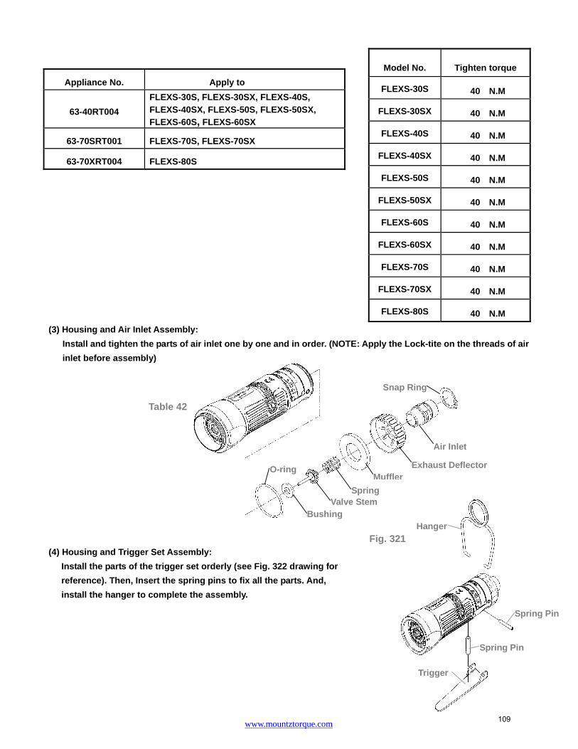
www.mountztorque.com
Spring Pin
Trigger
Spring Pin
Hanger
(3) Housing and Air Inlet Assembly:
Install and tighten the parts of air inlet one by one and in order. (NOTE: Apply the Lock-tite on the threads of air
inlet before assembly)
(4) Housing and Trigger Set Assembly:
Install the parts of the trigger set orderly (see Fig. 322 drawing for
reference). Then, Insert the spring pins to fix all the parts. And,
install the hanger to complete the assembly.
Model No. Tighten torque
FLEXS-30S 40 N.M
FLEXS-30SX 40 N.M
FLEXS-40S 40 N.M
FLEXS-40SX 40 N.M
FLEXS-50S 40 N.M
FLEXS-50SX 40 N.M
FLEXS-60S 40 N.M
FLEXS-60SX 40 N.M
FLEXS-70S 40 N.M
FLEXS-70SX 40 N.M
FLEXS-80S 40 N.M
Appliance No. Apply to
63-40RT004
FLEXS-30S, FLEXS-30SX, FLEXS-40S,
FLEXS-40SX, FLEXS-50S, FLEXS-50SX, FLEXS-60S, FLEXS-60SX
63-70SRT001 FLEXS-70S, FLEXS-70SX
63-70XRT004 FLEXS-80S
Fig. 321
Table 42
Valve StemSpring
MufflerExhaust Deflector
Air Inlet
Snap Ring
O-ring
Bushing
109

www.mountztorque.com
Driver series
Fig. 324
Wrench series
Fig. 322(5) Put the spring on the pin, and then install into the assembled housing.
After all the assembly is complete, test to make sure the anvil rotates smoothly, then connect the air
hose to test the torque.
General safety rules
For multiple hazards, read and understand the safety instructions before installing, operating, repairing, maintaining, changing accessories on, or working near the power tool. Failure to do so can result in serious bodily injury.
Only qualified and trained operators should install, adjust or use the power tool. Do not modify this power tool. Modifications can reduce the effectiveness of safety
measures and increase the risks to the operator. Do not discard the safety instructions; give them to the operator. Do not use the power tool if it has been damaged. Tools shall be inspected periodically to verify that the ratings and markings are legibly
MODEL Bolt Capacity Inserted Tools
FLEXS-30SX FLEXS-40SX FLEXS-50SX FLEXS-60SX FLEXS-70SX
M6 M6-M8
M8 M8
M8-M10 Unit : mm
FLEXS-30S ~ FLEXS-70S 3/8” power sockets
Pin
Spring
Fig. 323
110

www.mountztorque.com
marked on the tool. The employer/user shall contact the manufacturer to obtain replacement marking labels when necessary.
Projectile hazards
Be aware that failure of the work piece, of accessories or even of the inserted tool itself can generate high-velocity projectiles.
Always wear impact-resistant eye protection during the operation of the power tool. The grade of protection required should be assessed for each use. Ensure that the work piece is securely fixed.
Entanglement hazards
Entanglement hazards can result in choking, scalping and/or lacerations if loose clothing, personal jewellry, neck ware, hair or gloves are not kept away from the tool and accessories.
Gloves can become entangled with the rotating drive, causing severed or broken fingers.
Rotating drive sockets and drive extensions can easily entangle rubber-coated or metal-reinforced gloves.
Do not wear loose-fitting gloves or gloves with cut or frayed fingers. Never hold the drive, socket or drive extension. Keep hands away from rotating drives.
Operating hazards
The use of the tool can expose the operator's hands to hazards including crushing, impacts, cuts, abrasions and heat. Wear suitable gloves to protect hands.
Operators and maintenance personnel shall be physically able to handle the bulk, weight and power of the tool.
Hold the tool correctly; be ready to counteract normal or sudden movements and have both hands available.
Maintain a balanced body position and secure footing. In cases where the means to absorb the reaction torque are requested, it is
recommended to use a suspension arm whenever possible. If that is not possible, side handles are recommended for straight case and pistol-grip tools. Reaction bars are recommended for angle nut runners. In any case, it is recommended to use a means to absorb the reaction torque above 4 Nm for straight tools, above 10 Nm for pistol-grip tools, and above 60 Nm for angle nut runners.
Release the start-and-stop device in the case of an interruption of the energy supply. Use only lubricants recommended by the manufacturer. Fingers can be crushed in open-ended crow-foot nut runners. Do not use in confined spaces and beware of crushing hands between tool and
work piece, especially when unscrewing. Repetitive motions hazards
When using a power tool, the operator can experience discomfort in the hands, arms, 111

www.mountztorque.com
shoulders, neck, or other parts of the body. While using a power tool, the operator should adopt a comfortable posture whilst
maintaining secure footing and avoiding awkward or off-balanced postures. The operator should change posture during extended tasks, which can help avoid discomfort and fatigue.
If the operator experiences symptoms such as persistent or recurring discomfort, pain, throbbing, aching, tingling, numbness, burning sensations or stiffness, these warning signs should not be ignored. The operator should tell the employer and consult a
qualified health professional.
Accessory hazards
Disconnect the power tool from the energy supply before changing the inserted tool or accessory.
Do not touch sockets or accessories during impacting, as this increases the risk of cuts, burns or vibration injuries.
Use only sizes and types of accessories and consumables that are recommended by the power tool manufacturer.
Use only impact-wrench-rated sockets in good condition, as poor condition or hand sockets and accessories used with impact wrenches can shatter and become a projectile.
Workplace hazards
Slips, trips and falls are major causes of workplace injury. Be aware of slippery surfaces caused by the use of the tool and also of trip hazards caused by the air line or hydraulic hose.
Proceed with care in unfamiliar surroundings. Hidden hazards, such as electricity or other utility lines, can exist.
The power tool is not intended for use in potentially explosive atmospheres and is not insulated against coming into contact with electric power. Make sure there are no electrical cables, gas pipes, etc., that can cause a hazard if
damaged by use of the tool.
Dust and fume hazards
Dust and fumes generated when using power tools can cause ill health (for example, cancer, birth defects, asthma and/or dermatitis); risk assessment and implementation of appropriate controls for these hazards are essential.
Risk assessment should include dust created by the use of the tool and the potential for disturbing existing dust.
Direct the exhaust so as to minimize disturbance of dust in a dust-filled environment. Where dust or fumes are created, the priority shall be to control them at the point of
emission. All integral features or accessories for the collection, extraction or suppression of
airborne dust or fumes should be correctly used and maintained in accordance with the manufacturer's instructions.
112

www.mountztorque.com
Use respiratory protection in accordance with employer's instructions and as required by occupational health and safety regulations.
Noise hazards
Unprotected exposure to high noise levels can cause permanent, disabling, hearing loss and other problems, such as tinnitus (ringing, buzzing, whistling or humming in the ears). Risk assessment and implementation of appropriate controls for these hazards are essential. Appropriate controls to reduce the risk may include actions such as damping materials to prevent work pieces from “ringing”. Use hearing protection in accordance with employer's instructions and as required by occupational health and safety regulations. Operate and maintain the power tool as recommended in the instruction handbook, to prevent an unnecessary increase in noise levels. If the power tool has a silencer, always ensure it is in place and in good working order when the power tool is operating. Select, maintain and replace the consumable/inserted tool as recommended in the instruction hand book, to prevent an unnecessary increase in noise. Vibration hazards
Exposure to vibration can cause disabling damage to the nerves and blood supply of the hands and arms. Keep the hands away from the nut runner sockets. Wear warm clothing when working in cold conditions and keep your hands warm and dry. If you experience numbness, tingling, pain or whitening of the skin in your fingers or hands, stop using the power tool, tell your employer and consult a physician. Operate and maintain the power tool as recommended in the instruction handbook, to prevent an unnecessary increase in vibration levels. Do not use worn or ill-fitting sockets or extensions, as this is likely to cause a substantial increase in vibration. Select, maintain and replace the consumable/inserted tool as recommended in the instruction handbook, to prevent an unnecessary increase in vibration levels. Sleeve fittings should be used where practicable. Support the weight of the tool in a stand, tensioner or balancer, if possible. Hold the tool with a light but safe grip, taking account of the required hand reaction forces, because the risk from vibration is generally greater when the grip force is higher. Additional safety instructions for pneumatic power tool
Air under pressure can cause severe injury
Always shut off air supply, drain hose of air pressure and disconnect tool from air supply when not in use, before changing accessories or when making repairs
113

www.mountztorque.com
Fig. 327
Never direct air at yourself or anyone else. Whipping hoses can cause severe injury. Always check for damaged or loose hoses
and fittings. Cold air shall be directed away from the hands. Do not use quick-disconnect couplings at tool inlet for impact and air-hydraulic impulse
wrenches. Use hardened steel (or material with comparable shock resistance)threaded hose fittings.
Whenever universal twist couplings (claw couplings) are used, lock pins shall beinstalled and whipcheck safety cables shall be used to safeguard against possiblehose-to-tool and hose-and-hose connection failure.
Do not exceed the maximum air pressure stated on the tool. For torque-control and continuous-rotation tools, the air pressure has a safety critical
effect on performance. Therefore, requirements for length and diameter of the hose shall be specified.
Never carry an air tool by the hose.
Steps for Torque Adjustment – Angle Series
1. Remove the angle housing kit by loosening the lock nut in counter clockwise direction.
2. Rotate the anvil manually; adjust the valve screw inside the pulse unit to the hole; where the screw taken off.
Then, use the attached tool to adjust the torque. Torque increased by turning clockwise and vise versa.
Lock Nut
Increase torque
Reduce torque
Fig. 325
Fig. 326 114

www.mountztorque.com
Fig. 330 Fig. 331
Lock Nut
Lock Nut
3. Install the angle housing kit back by tightening the lock nut in clockwise direction to the housing.
DISASSEMBLEY/ASSEMBLEY FOR ANGLE SERIES - FLEX-50R, FLEX-60R, FLEX-70R, FLEX-50RX, FLEX-60RX, FLEX-70RX, FLEX-70RG, FLEX-70RH, FLEX-80RH
IMPULSE MECHANISM DISASSEMBLY
(1) Spring Holder disassembly: (for Model No. FLEX-50RX, FLEX-60RX, FLEX-70RX)
Use an acicular piece to get the spring holder out, then take the steel ball.
The steel ball may drop off when taking out the spring holder.
(2) Angle Housing Unit Disassembly:
Use an adjustable wrench counter clockwise to loosen the lock nut of the pulse unit housing. Then, take off
the angle unit.
Use 2mm L-type wrench counter clockwise to loosen the screws.
Fig. 328
Vise
Spring Holder
Note: Handle rubber must be covered by a piece of cloth to avoid damage
Fig. 329
115

www.mountztorque.com
Fig. 333
Shaft Gear
ShaftBall Bearing
Lock Nut
O-ring Ball Bearing
Greasing Screw
Washer
Shaft Gear
Shaft
Screw
Anvil Collar
Main Shaft Gear
Washer Ball Bearing
Ball Bearing
Lock Nut
O-ring
Lock Nut
Ball Bearing
Greasing ScrewScrew
Anvil Collar
Main Shaft Gear
Washer Ball Bearing
Ball Bearing
Lock Nut
O-ring
Lock Nut
Lock Nut
O-ring Ball Bearing
Washer
Ball Bearing
Steel ball
Spring Holder
Shaft
Shaft Gear
Fig. 332
Fix the angle unit. Use the torque wrench and the appliance to loosen the lock nut of the shaft gear counter
clockwise. Then take off some parts. See the Table 43 for selecting the proper appliance.
NOTE: Lock-tite might be applied when assembling the gear shaft.
Fix the angle unit. Use the torque wrench and the appliance to loosen the lock nut of the main shaft gear
counter clockwise. Then take off the remaining parts. See the Table 44 for selecting the proper appliance.
NOTE: Lock-tite might be applied when assembling the main gear shaft.
Parts of Angle Housing Unit:
a. FLEX-50R、FLEX-60R、FLEX-70R b. FLEX-50RX、FLEX-60RX、FLEX-70RX
Appliance No. Apply to
63-50RRT001 FLEX-50R, FLEX-50RX FLEX-60R, FLEX-60RX FLEX-70R, FLEX-70RX
63-70RHRT001 FLEX-70RG, FLEX-70RH
FLEX-80RH
Appliance No. Apply to
63-50RRT002 FLEX-50R, FLEX-50RX FLEX-60R, FLEX-60RX FLEX-70R, FLEX-70RX
63-70RHRT002 FLEX-70RG, FLEX-70RH
FLEX-80RH
Table 43
Table 44
Appliance
Appliance
116

www.mountztorque.com
Greasing Screw
O-ring
Screw
Ball Bearing
Shaft
Shaft Gear
Ball Bearing O-ring
Lock Nut
Main Shaft GearWasher
Ball Bearing
Anvil Collar
Lock Nut
Lock NutBall Bearing
Lock Nut
O-ring
Ball Bearing
Greasing Screw
Washer
Shaft Gear
Shaft
Ball Bearing
Screw
Anvil Collar
Main Shaft Gear
Washer Ball Bearing
Ball Bearing Lock Nut
O-ring
Lock Nut
Appliance
c. FLEX-70RG、FLEX-70RH d. FLEX-80RH
(2)Pulse Unit Housing Disassembly:
Fix the tool by a vise, use an adjustable wrench clockwise to loosen the pulse unit housing until the pulse unit
housing detach from the motor housing. Then, take the pulse unit out, Fig. 334.
(3) Pulse Unit Disassembly:
Fix the pulse unit by a vise. Use the appliance (see Table 45) to loosen the lock nut on the pulse unit, Fig. 335.
Note: Lock-tite was applied on the luck nut when tools were assembled.
Appliance No. Apply to
63-40RT001 FLEX-50R, FLEX-50RX
FLEX-60R, FLEX-60RX
63-70RT001
FLEX-70R, FLEX-70RX,
FLEX-70RG, FLEX-70RH,
FLEX-80RH
Table 45 Fig. 335
Vise
Note: Handle rubber must be covered by a piece of cloth toavoid damage
Fig. 334
117

www.mountztorque.com
Put the Appliance, see Table 46, on the anvil and tap on it slightly to detach the interior parts from the pulse
unit, Fig.336.
(5) Parts of Pulse Cylinder Unit:
a. FLEX-50R, FLEX-50RX, FLEX-60R, FLEX-60RX, FLEX-70R, FLEX-70RX
b. FLEX-70RG, FLEX-70RH, FLEX-80RH
Appliance No. Apply to
63-40RT002
FLEX-50R, FLEX-50RX,
FLEX-60R, FLEX-60RX,
FLEX-70R, FLEX-70RX,
FLEX-70RG, FLEX-70RH,
FLEX-80RH
Fig. 336
Table 46
Lock Nut
WasherO-Ring
Rear Plate
Block CapPulse Cylinder
Pin
PinO-Ring
Valve
Valve ScrewO-Ring
SpringPressure Valve
O-RingSpring
Drive BladeRoller
Anvil
Front PlatePin
X-Ring
Back UP RingSpring Pin
Front CoverGreasing Screw
O-Ring
O-Ring
Pulse Cylinder Seat
Back UP Ring
Lock NutWasher
O-RingRear Plate
Block Cap
Pin
Pin
Pulse CylinderSpring
Pressure Valve
O-Ring
O-RingValve
Valve Screw
O-Ring
Spring
Drive BladeRoller
Anvil
Front Plate
Pin
X-Ring
Back UP Ring
Front Cover
Spring Pin
O-RingGreasing Screw
O-Ring
Pulse Cylinder Seat
Back UP Ring
Appliance
118

www.mountztorque.com
Step 5; Fig. 341 Front Plate
Corresponding position
Small Hole
Big Hole
O-ring
Step 1; Fig. 338
Valve Screw
Step 2; Fig. 339
Pin
PULSE UNIT ASSEMBLY:
(1) Pulse Cylinder Unit Assembly:
Install the pins on both sides of the pulse cylinder. (Fig. 337)
Sleeve the o-ring to the valve and install the valve into the big hole on the pulse cylinder. (Step 1; Fig.338)
Insert the pin into the hole on the side of the pulse cylinder. (Step 2; Fig.339)
Tighten the valve screw left thread to the pressure valve. (Step 3; Fig.339)
NOTE: the valve screw MUST tighten to the most bottom position certainly.
Put the spring into the hole then install the pressure valve that with the o-ring sleeved. (Step 4; Fig. 340)
Install the front plate and make sure the corresponding position with the pins. (Step 5; Fig. 341)
Pin
Pin
Pulse CylinderFig. 337
Pressure Valve
Spring
Step 4; Fig. 340
119

www.mountztorque.com
(2) Anvil Unit Assembly:
Install the roller to the drive blade, then insert the springs into the anvil and press the blades from both sides.
Finally put the anvil to the pulse cylinder to complete the anvil unit assembly.
MUST follow the direction as Fig.81 showed while installing the anvil unit into the pulse cylinder; be sure to aim at the highest points by two sides of the interior pulse unit and press the two drive blades in slowly. NOTE: IT IS RECOMMENDED TO USE THE SPECIAL FIXTURE FOR EASIER INSTALLATION OF ANVIL WITH THE ROLLER AND THE BLADE INTO THE CYLINDER (No picture showed)
120

www.mountztorque.com
Press
Press
Fig. 344
Front Plate
(d) Fig. 348
Front Cover
MUST follow the direction as shown in Figure 344 while installing the anvil unit into the pulse cylinder; be
sure to aim at the highest points by two sides of the interior pulse unit and press the two drive blades in
slowly.
(3) Front Cover and Rear Plate of Pulse Cylinder Assembly
FLEX-50R, FLEX-50RX, FLEX-60R, FLEX-60RX, FLEX-70R, FLEX-70RX
(a) Put the O-ring on the Rear Plate and install the rear plate to the pulse cylinder, Be sure the positions of
the pin and the hole are corresponded. (Fig. 345)
(b) Put the X-ring and Back up ring on the anvil with the oil applied. (Fig. 346)
(c) Put the Back up ring and O-ring into the Valve Screw.(Fig. 347)
(d) Install the front cover to the pulse cylinder by the corresponding positions. (Fig. 348)
After installing the front cover, put the o-ring on the greasing screw, then tighten the greasing screw but
release it a little bit after completely tightened.
FLEX-70RG, FLEX-70RH, FLEX-80RH
(a) Put the O-ring on the Rear Plate and install the rear plate to the pulse cylinder, Be sure the positions of
Spring
Fig. 342
Roller
Drive Blade
Fig. 343
O-ring
Rear Plate
(a) Fig. 345
Back Up Ring
X-ring
(b) Fig. 346
Corresponding position
(c) Fig. 347
O-ring
Back Up Ring
Greasing Screw O-ring
Fig. 349
121

www.mountztorque.com
O-ring
Greasing Screw
the pin and the hole are corresponded. (Fig.350)
(b) Put the X-ring and Back up ring on the anvil with the oil applied. (Fig.351)
(c) Put the Back up ring and O-ring into the Valve Screw.(Fig. 352)
(d) Install the front cover to the pulse cylinder by the corresponding positions.(Fig. 353)
After installing the front cover, put the o-ring on the greasing screw, then tighten the greasing screw but
release it a little bit after completely tightened.
(4) Pulse Cylinder Seat and Lock Nut of Pulse Cylinder Assembly
Place the o-ring inside the bottom of the pulse cylinder seat, then combine the pulse cylinder seat with the
assembled pulse cylinder unit. (Fig. 355, Fig. 356)
Make sure the half-circle gaps aim at the corresponding positions.
(a) Fig. 350
O-ring
Rear Plate
X-ring
(b) Fig. 351
Corresponding position
(d) Fig. 353
O-ring
Pulse Cylinder Seat
Fig. 355
(c) Fig. 352
O-ring
Back Up Ring
Front Cover
Fig. 354
Back Up Ring
Half-circle gaps
Pin
O-ringFig. 356
Pulse Cylinder Seat
Greasing Screw
122

www.mountztorque.com
Use the appliance to push out the rear plate from the pulse cylinder seat. See Table 46 in reference to the
proper appliance selection. (Fig. 357)
Fill up the interior pulse cylinder with the pulse oil about 90% full by an injector. (Fig. 358)
Install the rear plate taken from the step 2 on the pulse cylinder. Note the corresponding positions!
Turn the assembled unit up side down so the rear plate is at the bottom. Then press the pulse cylinder seat
all the way down to the fixed position. Make sure the corresponding positions are matched exactly.
Fix the pulse cylinder seat by a vise. Use an appliance and a torque wrench, and then turn clockwise to
tighten the lock nut of the pulse cylinder. See Table 47 and 48 in reference to the proper appliance and
tightness. (Note: Lock-tite needed when tightening the lock nut of the pulse cylinder)
Appliance No. Apply to
63-40RT001 FLEX-50R, FLEX-50RX, FLEX-60R, FLEX-60RX
63-70RT001 FLEX-70R, FLEX-70RX, FLEX-70RG, FLEX-70RH, FLEX-80RH
Model No. Tighten torque
FLEX-50R 80 N.M
FLEX-50RX 80 N.M
FLEX-60R 80 N.M
FLEX-60RX 80 N.M
FLEX-70R 100 N.M
Model No. Tighten torque
FLEX-70RX 100 N.M
FLEX-70RG 100 N.M
FLEX-70RH 100 N.M
FLEX-80RH 100 N.M
Table 47
Table 48
Fig. 357
Appliance
Rear Plate
Fig. 358 Fig. 359 Fig. 360
Appliance
Fig. 361Fixed by a vise
Rear Plate
123

www.mountztorque.com
Fig. 362
Fig. 363
Fig. 364
After completing the above steps, test to make sure the square drive of the anvil rotates smoothly.
(5) Steps for Pulse Cylinder Oiling:
Loosen the greasing screw, and fill in the authorized oil by an injector until it is full and overflow.
Take the unit and dip it in an oil tank, then rotate the anvil by a wrench to release air inside, in the mean
time, the unit would be full with oil completely.
Use the screwdriver either ,the slotted to tighten the greasing screw, Fig. 365.
Use an air spray gun to blow off the oil on the cylinder seat, Fig. 366.
Fig. 365
O-ring
Greasing Screw Slotted
124

www.mountztorque.com
Loosen the greasing screw again and use an injector to draw out a little
amount of oil ( see Table 49) . Finally, tighten the greasing screw back to the
pulse cylinder unit, Fig. 367.
(6) Torque Testing:
Put the washer on the front end of the anvil, then put another washer on the rear plate.
Model No. Amount of oil draw
FLEX-50R 0.35 CC
FLEX-50RX 0.35 CC
FLEX-60R 0.45 CC
FLEX-60RX 0.45 CC
FLEX-70R 0.63 CC
Model No. Amount of oil draw
FLEX-70RX 0.63 CC
FLEX-70RG 0.63 CC
FLEX-70RH 0.63 CC
FLEX-80RH 0.6 CC
Fig. 367
Table 49
Washer
Anvil
Washer
Rear Plate
Fig. 368
125

www.mountztorque.com
Tighten the clutch housing by hands.
Test the forward torque by a digital torque tester and make sure the tool pulses smoothly.
Model No. Air inlet pressure 0.6 Mpa
N.M (at least)
FLEX-50R 17
FLEX-50RX 16
FLEX-60R 24
FLEX-60RX 22
FLEX-70R 31
FLEX-70RX 29
FLEX-70RG 50
FLEX-70RH 60
FLEX-80RH 70
Table 50
Digital Torque Tester
Fig. 369
Driver series Wrench series RG、RH series
Fig. 370
126

www.mountztorque.com
Note: Handle rubber must be covered by a piece of cloth to avoid damage
If the test result is NG (see Table 50 in reference to the torque standard), MUST draw out or add a little
amount of oil and do the following steps:
Loosen the pulse unit housing by hands.
Loosen the greasing screw.
Draw out or add a little amount of oil.
Tighten the greasing screw back.
Tighten the pulse unit housing.
Test the torque again. If the test result is still NG, repeat the Steps ~until the standard torque
is reached.
(7) Pulse Unit Housing Assembly:
Fix the housing by a vise. Turn the wrench in counter clockwise direction to tighten the pulse unit housing.
(8) Angle Housing Unit Assembly:
Assemble the parts in Fig. 372 one by one orderly into the angle housing. Then, fix the angle housing unit.
Use the torque wrench and the appliance clockwise to tighten the lock nut of the shaft gear. See Table 51 in
reference to the proper appliance selecting.
Note: (1) Make sure to apply the grease on the gear.
(2) Make sure to apply the lock-tite on the lock nut of the shaft gear.
Assemble the parts in Fig. 374 one by one orderly into the angle housing. Then, fix the angle housing unit. Use
the torque wrench and the appliance clockwise to tighten the lock nut of the main shaft gear. See Table 52 in
reference to the proper appliance selecting.
Note:(1) Make sure to apply the grease on the gear.
Appliance No. Apply to
63-50RRT001 FLEX-50R, FLEX-50RX FLEX-60R, FLEX-60RX FLEX-70R, FLEX-70RX
63-70RHRT001 FLEX-70RG, FLEX-70RH
FLEX-80RH
Appliance
Table 51
Fig. 372
Fig. 373
Fig. 371
Angle Housing Ball Bearing
Shaft
Shaft Gear
Washer
Ball Bearing
O-ring
Lock Nut
127

www.mountztorque.com
Fig. 378
Fig. 376
Fig. 374
Main Shaft Gear
Washer
Ball Bearing
Ball Bearing
Lock Nut
Screw
Fig. 377
Applianc
Fig.
(2) Make sure to apply the lock-tite on the lock nut of the main shaft gear.
Use 2mm L-type wrench clockwise to loosen the screws. Assemble the angle housing unit to the pulse unit housing and use the torque wrench clockwise to tighten
it.
Appliance No. Apply to
63-50RRT002 FLEX-50R, FLEX-50RX FLEX-60R, FLEX-60RX FLEX-70R, FLEX-70RX
63-70RHRT002 FLEX-70RG, FLEX-70RH
FLEX-80RH
Table 52
128

www.mountztorque.com
HOUSING AND MOTOR SET DISASSEMBLY:
(1) Cylinder Unit Disassembly:
Fix the tool by a vise. Use the appliance (see Table 53) to take the lock nut out of cylinder by turning
clockwise.
Use a wrench to loosen the screw on the side of the motor housing and detach the parts of the regulator.
Take a piece of cloth and lay it on a table before disassembly. Hold the housing downward to detach the
cylinder unit out.
Appliance No. Apply to
63-40RT004 FLEX-50R, FLEX-50RX FLEX-60R, FLEX-60RX
63-70SRT001
FLEX-70R, FLEX-70RX
FLEX-70RG, FLEX-70RH
FLEX-80RH
Fig. 381
Table 53
Appliance
Note: Handle rubber must be covered by a piece of cloth to avoid damage Lock Nut of Cylinder Fig. 379
Screw
Regulator
Fig. 380
129
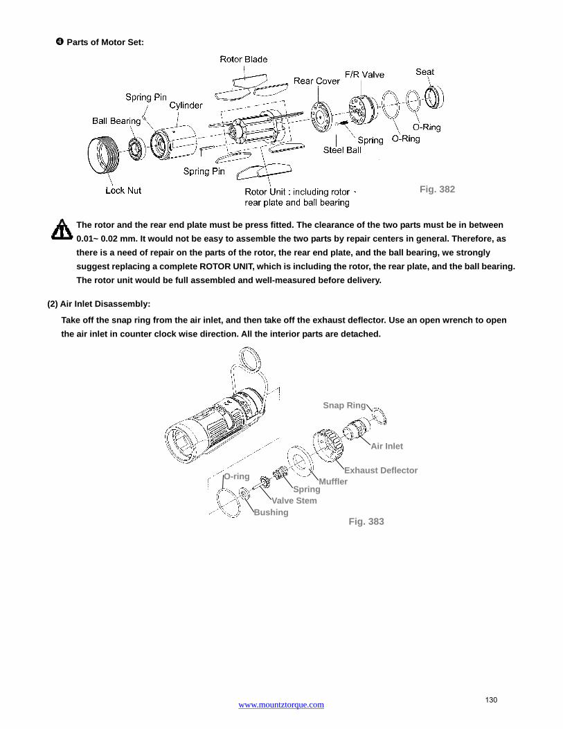
www.mountztorque.com
Spring
Air Inlet
Muffler Exhaust Deflector
Snap Ring
O-ring
Valve Stem Bushing
Fig. 383
Parts of Motor Set:
The rotor and the rear end plate must be press fitted. The clearance of the two parts must be in between
0.01~ 0.02 mm. It would not be easy to assemble the two parts by repair centers in general. Therefore, as
there is a need of repair on the parts of the rotor, the rear end plate, and the ball bearing, we strongly
suggest replacing a complete ROTOR UNIT, which is including the rotor, the rear plate, and the ball bearing.
The rotor unit would be full assembled and well-measured before delivery.
(2) Air Inlet Disassembly:
Take off the snap ring from the air inlet, and then take off the exhaust deflector. Use an open wrench to open
the air inlet in counter clock wise direction. All the interior parts are detached.
Fig. 382
130

www.mountztorque.com
(3) Trigger Set Disassembly:
Remove the spring pin from the trigger to detach the interior parts. And then, remove the housing rubber and
the hanger to complete the disassembly.
HOUSING AND MOTOR SET ASSEMBLY:
(1) Cylinder Unit Assembly
Place the rotor blades into the rotor. Insert the spring pin A
and B into the cylinder. Make sure the pins aim at the pin
holes when putting the cylinder down.
Make the groove of the air inlet plate toward the rear end plate and assemble. Make sure the holes aim at
the pin while assembling, Fig. 387.
Assemble the regulator with the rotor- air inlet unit. Make sure the steel balls of the regulator are placed
on the holes of the air inlet plate. Then, place the seat with the o-ring sleeved on the regulator. Assembly
is completed.
Apply the lubricator between parts while assembling.
Grooves
Seat
O-ring
Fig. 389
Regulator
Seat
Holes
O-ring
Steel Balls
Fig. 388
Spring Pin Fig. 387
Air Inlet Plate
Rear Plate
O-ring
Fig. 384
Trigger
Pin
Spring Pin
Fig. 385 Housing
Hanger
Housing Rubber
Fig. 386
Rotor unit
Spring A
Spring B
131

www.mountztorque.com
Fig. 392Note: Handle rubber must be covered by a piece of cloth to avoid damage
(2) Housing, Motor set unit and Lock Nut of Cylinder Assembly:
Put the housing rubber on the housing.
Install the motor set into the housing. Make sure the direction is correct, i.e. the spring pin on the side of
the cylinder aims at the hole inside the housing.
Have the hole on the regulator aim at the screw hole on the side of the F/R valve and make sure the screw
is tightened into the regulator and the F/R valve.
Fix the tool by a vise. Place the lock nut of the cylinder nut and tighten by the appliance in counter clockwise
direction to complete the assembly. See the Table 54 and 55 in reference to appliance use and tighten torque.
(3) Housing and Air Inlet Assembly:
Install and tighten the parts of air inlet one by one and in order. (NOTE:
Apply the Lock-tite on the threads of air inlet before assembly)
Model No. Tighten torque
FLEX-50R 40 N.M
FLEX-50RX 40 N.M
FLEX-60R 40 N.M
FLEX-60RX 40 N.M
FLEX-70R 40 N.M
FLEX-70RX 40 N.M
FLEX-70RG 40 N.M
FLEX-70RH 40 N.M
FLEX-80RH 40 N.M
Appliance No. Apply to
63-40RT004 FLEX-50R, FLEX-50RX
FLEX-60R, FLEX-60RX
63-70SRT001 FLEX-70R, FLEX-70RX,
FLEX-70RG, FLEX-70RH, FLEX-80RH
Appliance
Fig. 417
Fig. 390
Fig. 392
Table 54
Table 55
Screw
Screw of F/R valve
Regulator
Fig. 391
Spring Pin
Screw of F/R valve
Hole inside the housing
Motor Set Unit
132

www.mountztorque.com
Fig. 395
Spring Pin
Trigger
Spring Pin
Hanger
Fig. 394
(4) Housing and Trigger Set Assembly:
Install the parts of the trigger set orderly (see Fig. 394
drawing for reference). Then, Insert the spring pins to fix all
the parts. And, install the hanger to complete the assembly.
After all the assembly is complete, test to make sure the anvil rotates smoothly, then connect the air
hose to test the torque.
MODEL Bolt Capacity Inserted Tools
FLEX-50RX FLEX-60RX FLEX-70RX
M6-M8
M8 M8
Unit : mm
FLEX-50R ~ FLEX-70R and FLEX-70RG
3/8” power sockets
FLEX-70RH 1/2” power sockets
General safety rules
For multiple hazards, read and understand the safety instructions before installing, operating, repairing, maintaining, changing accessories on, or working near the power tool. Failure to do so can result in serious bodily injury.
Only qualified and trained operators should install, adjust or use the power tool. Do not modify this power tool. Modifications can reduce the effectiveness of safety
Valve Stem Spring
Muffler
Exhaust Deflector
Air Inlet
Snap Ring
O-ring
Bushing
133

www.mountztorque.com
measures and increase the risks to the operator. Do not discard the safety instructions; give them to the operator. Do not use the power tool if it has been damaged. Tools shall be inspected periodically to verify that the ratings and markings are legibly
marked on the tool. The employer/user shall contact the manufacturer to obtain replacement marking labels when necessary.
Projectile hazards
Be aware that failure of the work piece, of accessories or even of the inserted tool itself can generate high-velocity projectiles.
Always wear impact-resistant eye protection during the operation of the power tool. The grade of protection required should be assessed for each use. Ensure that the work piece is securely fixed.
Entanglement hazards
Entanglement hazards can result in choking, scalping and/or lacerations if loose clothing, personal jewelry, neck ware, hair or gloves are not kept away from the tool and accessories.
Gloves can become entangled with the rotating drive, causing severed or broken fingers.
Rotating drive sockets and drive extensions can easily entangle rubber-coated or metal-reinforced gloves.
Do not wear loose-fitting gloves or gloves with cut or frayed fingers. Never hold the drive, socket or drive extension. Keep hands away from rotating drives.
Operating hazards
The use of the tool can expose the operator's hands to hazards including crushing, impacts, cuts, abrasions and heat. Wear suitable gloves to protect hands.
Operators and maintenance personnel shall be physically able to handle the bulk, weight and power of the tool.
Hold the tool correctly; be ready to counteract normal or sudden movements and have both hands available.
Maintain a balanced body position and secure footing. In cases where the means to absorb the reaction torque are requested, it is
recommended to use a suspension arm whenever possible. If that is not possible, side handles are recommended for straight case and pistol-grip tools. Reaction bars are recommended for angle nut runners. In any case, it is recommended to use a means to absorb the reaction torque above 4 Nm for straight tools, above 10 Nm for pistol-grip tools, and above 60 Nm for angle nut runners.
Release the start-and-stop device in the case of an interruption of the energy supply. Use only lubricants recommended by the manufacturer. Fingers can be crushed in open-ended crow-foot nut runners.
134

www.mountztorque.com
Do not use in confined spaces and beware of crushing hands between tool and work piece, especially when unscrewing.
Repetitive motions hazards
When using a power tool, the operator can experience discomfort in the hands, arms, shoulders, neck, or other parts of the body.
While using a power tool, the operator should adopt a comfortable posture whilst maintaining secure footing and avoiding awkward or off-balanced postures. The operator should change posture during extended tasks, which can help avoid discomfort and fatigue.
If the operator experiences symptoms such as persistent or recurring discomfort, pain, throbbing, aching, tingling, numbness, burning sensations or stiffness, these warning signs should not be ignored. The operator should tell the employer and consult a
qualified health professional.
Accessory hazards
Disconnect the power tool from the energy supply before changing the inserted tool or accessory.
Do not touch sockets or accessories during impacting, as this increases the risk of cuts, burns or vibration injuries.
Use only sizes and types of accessories and consumables that are recommended by the power tool manufacturer.
Use only impact-wrench-rated sockets in good condition, as poor condition or hand sockets and accessories used with impact wrenches can shatter and become a projectile.
Workplace hazards
Slips, trips and falls are major causes of workplace injury. Be aware of slippery surfaces caused by the use of the tool and also of trip hazards caused by the air line or hydraulic hose.
Proceed with care in unfamiliar surroundings. Hidden hazards, such as electricity or other utility lines, can exist.
The power tool is not intended for use in potentially explosive atmospheres and is not insulated against coming into contact with electric power. Make sure there are no electrical cables, gas pipes, etc., that can cause a hazard if
damaged by use of the tool.
Dust and fume hazards
Dust and fumes generated when using power tools can cause ill health (for example, cancer, birth defects, asthma and/or dermatitis); risk assessment and implementation of appropriate controls for these hazards are essential.
Risk assessment should include dust created by the use of the tool and the potential for disturbing existing dust.
Direct the exhaust so as to minimize disturbance of dust in a dust-filled environment. 135

www.mountztorque.com
Where dust or fumes are created, the priority shall be to control them at the point of emission.
All integral features or accessories for the collection, extraction or suppression of airborne dust or fumes should be correctly used and maintained in accordance with the manufacturer's instructions.
Use respiratory protection in accordance with employer's instructions and as required by occupational health and safety regulations.
Noise hazards
Unprotected exposure to high noise levels can cause permanent, disabling, hearing loss and other problems, such as tinnitus (ringing, buzzing, whistling or humming in the ears). Risk assessment and implementation of appropriate controls for these hazards are essential. Appropriate controls to reduce the risk may include actions such as damping materials to prevent work pieces from “ringing”. Use hearing protection in accordance with employer's instructions and as required by occupational health and safety regulations. Operate and maintain the power tool as recommended in the instruction handbook, to prevent an unnecessary increase in noise levels. If the power tool has a silencer, always ensure it is in place and in good working order when the power tool is operating. Select, maintain and replace the consumable/inserted tool as recommended in the instruction hand book, to prevent an unnecessary increase in noise. Vibration hazards
Exposure to vibration can cause disabling damage to the nerves and blood supply of the hands and arms. Keep the hands away from the nut runner sockets. Wear warm clothing when working in cold conditions and keep your hands warm and dry. If you experience numbness, tingling, pain or whitening of the skin in your fingers or hands, stop using the power tool, tell your employer and consult a physician. Operate and maintain the power tool as recommended in the instruction handbook, to prevent an unnecessary increase in vibration levels. Do not use worn or ill-fitting sockets or extensions, as this is likely to cause a substantial increase in vibration. Select, maintain and replace the consumable/inserted tool as recommended in the instruction handbook, to prevent an unnecessary increase in vibration levels. Sleeve fittings should be used where practicable. Support the weight of the tool in a stand, tensioner or balancer, if possible. Hold the tool with a light but safe grip, taking account of the required hand reaction forces, because the risk from vibration is generally greater when the grip force is higher.
136

www.mountztorque.com
Additional safety instructions for pneumatic power tool
Air under pressure can cause severe injury
Always shut off air supply, drain hose of air pressure and disconnect tool from air supply when not in use, before changing accessories or when making repairs
Never direct air at yourself or anyone else. Whipping hoses can cause severe injury. Always check for damaged or loose hoses
and fittings. Cold air shall be directed away from the hands. Do not use quick-disconnect couplings at tool inlet for impact and air-hydraulic impulse
wrenches. Use hardened steel (or material with comparable shock resistance) threaded hose fittings.
Whenever universal twist couplings (claw couplings) are used, lock pins shall be installed and whipcheck safety cables shall be used to safeguard against possible hose-to-tool and hose-and-hose connection failure.
Do not exceed the maximum air pressure stated on the tool. For torque-control and continuous-rotation tools, the air pressure has a safety critical effect on performance. Therefore, requirements for length and diameter of the hose shall be specified. Never carry an air tool by the hose.
137

www.mountztorque.com
Lock Nut
Fig. 397 Fig. 398
Fig. 399
DISASSEMBLEY/ASSEMBLEY FOR ANGLE SERIES - FLEXS-50R, FLEXS-60R, FLEXS-70R, FLEXS-50RX, FLEXS-60RX, FLEXS-70RX, FLEXS-70RG, FLEXS-70RH,
FLEXS-80RH
IMPULSE MECHANISM DISASSEMBLY
(1) Spring Holder disassembly: (for Model No. FLEXS-50RX, FLEXS-60RX, FLEXS-70RX)
Use an acicular piece to get the spring holder out, then take the steel ball.
The steel ball may drop off when taking out the spring holder.
(2) Angle Housing Unit Disassembly:
Use an adjustable wrench counterclockwise to loosen the lock nut of the pulse unit housing. Then, take off
the angle unit.
Use 2mm L-type wrench counterclockwise to loosen the screws.
Fix the angle unit. Use the torque wrench and the appliance to loosen the lock nut of the shaft gear
counterclockwise. Then take off some parts. See the Table 56 for selecting the proper appliance.
NOTE: Lock-tite might be applied when assembling the gear shaft.
Appliance No. Apply to
63-50RRT001 FLEXS-50R, FLEXS-50RX FLEXS-60R, FLEXS-60RX FLEXS-70R, FLEXS-70RX
63-70RHRT001 FLEXS-70RG, FLEXS-70RH
FLEXS-80RH
Table 56
Appliance
Vise
Spring Holder
Note: Handle rubber must be
covered by a piece of cloth to
avoid damage
Fig. 396
138

www.mountztorque.com
Fig. 400
Ball Bearing
Greasing Screw
O-ring
Screw
Lock Nut
O-ring
Ball Bearing
Shaft Gear
Shaft
Ball Bearing
Main Shaft Gear
Washer Ball Bearing
Ball Bearing Lock Nut
Lock Nut
Anvil Collar
Lock Nut
O-ring
Ball Bearing
Greasing Screw
Washer
Shaft Gear
Shaft
Screw
Anvil Collar
Main Shaft Gear
Washer Ball Bearing
Ball Bearing
Lock Nut
O-ring
Lock Nut
Ball Bearing
Lock Nut O-ring
Ball Bearing
Greasing Screw
Washer
Shaft Gear
Shaft Ball Bearing
Screw
Anvil Collar
Main Shaft Gear
Washer Ball Bearing
Ball Bearing Lock Nut
O-ring
Lock Nut
Greasing Screw Screw
Anvil Collar
Main Shaft Gear
Washer Ball Bearing
Ball Bearing
Lock Nut
O-ring
Lock Nut
Lock Nut
O-ring
Ball Bearing
Washer
Shaft Gear
Shaft
Ball Bearing
Steel ball
Spring Holder
Fix the angle unit. Use the torque wrench and the appliance to loosen the lock nut of the main shaft gear
counterclockwise. Then take off the remaining parts. See the Table 57 for selecting the proper appliance.
NOTE: Lock-tite might be applied when assembling the main gear shaft.
Parts of Angle Housing Unit:
a. FLEXS-50R、FLEXS-60R、FLEXS-70R b. FLEXS-50RX、FLEXS-60RX、FLEXS-70RX
c. FLEXS-70RG、FLEXS-70RH d. FLEXS-80RH
Appliance No. Apply to
63-50RRT002 FLEXS-50R, FLEXS-50RX FLEXS-60R, FLEXS-60RX FLEXS-70R, FLEXS-70RX
63-70RHRT002 FLEXS-70RG, FLEXS-70RH
FLEXS-80RH
Table 57
Appliance
139

www.mountztorque.com
Fig.7
Appliance
(3) Pulse Unit Housing Disassembly:
Fix the tool by a vise, use an adjustable wrench clockwise to loosen the pulse unit housing until the pulse unit
housing detach from the motor housing. Then, take the pulse unit out, Fig. 401.
(4) Pulse Unit Disassembly:
Fix the pulse unit by a vise. Use the appliance (see Table 58) to loosen the lock nut on the pulse unit,
Fig. 402.
Note: Lock-tite was applied on the luck nut when tools were assembled.
Put the Appliance, see Table 59, on the anvil and tap on it slightly to detach the interior parts from the pulse
unit, Fig. 403.
Appliance No. Apply to
63-40RT001 FLEXS-50R, FLEXS-50RX
FLEXS-60R, FLEXS-60RX
63-70RT001
FLEXS-70R, FLEXS-70RX
FLEXS-70RG, FLEXS-70RH
FLEXS-80RH
Appliance No. Apply to
63-40RT002
FLEXS-50R, FLEXS-50RX
FLEXS-60R, FLEXS-60RX
FLEXS-70R, FLEXS-70RX
FLEXS-70RG, FLEXS-70RH
FLEXS-80RH
Fig. 403 Table 59
Table 58 Fig. 402
Vise
Note: Handle rubber must be covered by a piece of cloth toavoid damage
Fig. 401
Appliance
140

www.mountztorque.com
Parts of Pulse Cylinder Unit:
a. FLEXS-50R, FLEXS-50RX, FLEXS-60R, FLEXS-60RX, FLEXS-70R, FLEXS-70RX
b. FLEXS-70RG, FLEXS-70RH, FLEXS-80RH
PULSE UNIT ASSEMBLY:
(1) Pulse Cylinder Unit Assembly:
Install the pins on both sides of the pulse cylinder. (Fig. 404)
Sleeve the o-ring to the valve and install the valve into the big hole on the pulse cylinder. (Step 1; Fig.405)
Insert the pin into the hole on the side of the pulse cylinder. (Step 2; Fig.406)
Tighten the valve screw left thread to the pressure valve. (Step 3; Fig.406)
NOTE: the valve screw MUST tighten to the most bottom position certainly.
Pressure Valve
O-Ring
Washer
Lock NutRear Plate
O-RingPin
Block Cap
Pulse Cylinder
Pin
Pin
Spring
Pressure ValveO-Ring
SpringSteel Ball
ValveO-Ring
Valve Screw
O-RingBlock Valve
Anvil
Drive Blade
Spring
RollerFront Plate
X-Ring
Back Up Ring
Front CoverSpring Pin
O-RingGreasing Screw
O-Ring
Pulse Cylinder Seat
Back Up Ring
Lock Nut
Pressure Valve
O-Ring
Washer
Rear PlateO-Ring
Block Cap
Pin
PinSpring
Pressure Valve
O-RingPulse Cylinder
PinSpring
Steel Ball
O-RingValve
Valve ScrewO-Ring
Block ValveSpring
Drive BladeRoller
AnvilFront Plate
X-Ring
Back Up Ring
Front Cover
Spring Pin
Greasing ScrewO-Ring
O-Ring
Pulse Cylinder Seat
Back Up Ring
Pin
Pin
Pulse CylinderFig. 404
141

www.mountztorque.com
Small Hole
Big Hole
O-ring
Step 1; Fig. 405
Valve Screw
Step 2; Fig. 406
Pin
Fig. 411
Front Plate
Press
Put the spring into the hole then install the pressure valve that with the o-ring sleeved.(Step 4; Fig. 407)
Install the front plate and make sure the corresponding position with the pins. (Step 5; Fig. 408)
(2) Anvil Unit Assembly:
Install the roller to the drive blade, then insert the springs into the anvil and press the blades from both sides.
Finally put the anvil to the pulse cylinder to complete the anvil unit assembly.
MUST follow the direction as shown in Figure 411 while installing the anvil unit into the pulse cylinder; be
sure to aim at the highest points by two sides of the interior pulse unit and press the two drive blades in
slowly.
Fig. 410 Fig. 409
Roller
Drive Blade
Step 5; Fig. 408 Front Plate
Corresponding position
Pressure Valve
Spring
Step 4; Fig. 407
Spring
Press
142

www.mountztorque.com
(d) Fig. 415
Front Cover
(3) Front Cover and Rear Plate of Pulse Cylinder Assembly
FLEXS-50R, FLEXS-50RX, FLEXS-60R, FLEXS-60RX, FLEXS-70R, FLEXS-70RX
(a) Put the O-ring on the Rear Plate and install the rear plate to the pulse cylinder, Be sure the positions of
the
pin and the hole are corresponded. (Fig. 412) Then, plug the pressure valve with the convex facing
outside in the hole on the rear plate.
(b) Put the X-ring and Back up ring on the anvil with the oil applied. (Fig. 413)
(c) Put the Back up ring and O-ring into the Valve Screw. (Fig. 414)
(d) Install the front cover to the pulse cylinder by the corresponding positions. (Fig. 415)
After installing the front cover, put the o-ring on the
greasing screw, then tighten the greasing screw but
release it a little bit after completely tightened. (Fig. 416)
FLEXS-70RG, FLEXS-70RH, FLEXS-80RH
(a) Put the O-ring on the Rear Plate and install the rear plate to the pulse cylinder, Be sure the positions of
the pin and the hole are corresponded. (Fig. 417) Then, plug the pressure valve with the convex facing
outside in the hole on the rear plate.
(b) Put the X-ring and Back up ring on the anvil with the oil applied. (Fig. 418)
(c) Put the Back up ring and O-ring into the Valve Screw. (Fig. 419)
(d) Install the front cover to the pulse cylinder by the corresponding positions. (Fig. 420)
Pressure Valve O-ring
O-ring
Rear Plate
(a) Fig. 412 (b) Fig. 413
Back Up Ring
X-ring
O-ring Pressure Valve
O-ring
Rear Plate
(a) Fig. 417 (b) Fig. 418 (d) Fig. 420
O-ring
Back Up Ring
(c) Fig. 414
(c) Fig. 419
Back Up Ring O-ring
Corresponding position
Greasing Screw O-ring Fig. 416
X-ring
Back Up Ring
Front Cover
Corresponding position
143

www.mountztorque.com
After installing the front cover, put the o-ring on the greasing screw, then tighten the greasing screw but
release it a little bit after completely tightened.
(4) Pulse Cylinder Seat and Lock Nut of Pulse Cylinder Assembly
Place the o-ring inside the bottom of the pulse cylinder seat, then combine the pulse cylinder seat with the
assembled pulse cylinder unit. (Fig. 422, Fig. 423)
Make sure the half-circle gaps aim at the corresponding positions.
Use the appliance to push out the rear plate from the pulse cylinder seat. See Table 55 in reference to the
proper appliance selection. (Fig.424)
Fill up the interior pulse cylinder with the pulse oil about 90% full by an injector. Put the steel ball and the
valve spring into the hole on the pulse cylinder in order. (Fig. 425)
Put the block valve into the rear plate taken out at Step 2, and then install the rear plate to the pulse cylinder.
Make sure the positions of the pins and the holes are exactly matched. (Fig.426)
Turn the assembled unit up side down so the rear plate is at the bottom. Then press the pulse cylinder seat
all the way down to the fixed position. Make sure the corresponding positions are matched exactly.
O-ring
Pulse Cylinder Seat
Fig. 422
Fig. 425
Valve Spring
Steel Ball
Fig. 421 O-ring
Greasing Screw
Rear Plate
Fig. 426
Block Valve
Fig. 427
Half-circle gaps
Pin
O-ringFig. 423
Pulse Cylinder Seat
Greasing Screw
Fig. 424
Appliance
Rear Plate
144

www.mountztorque.com
Fig. 429
Fig. 430
Fix the pulse cylinder seat by a vise. Use an appliance and a torque wrench, and then turn clockwise to
tighten the lock nut of the pulse cylinder. See Table 60 and 61 in reference to the proper appliance and
tightness. (Note: Lock-tite needed when tightening the lock nut of the pulse cylinder)
After completing the above steps, test to make sure the square drive of the anvil rotates smoothly.
(5) Steps for Pulse Cylinder Oiling:
Loosen the greasing screw, and fill in the authorized oil by an injector until it is full and overflow.
Appliance No. Apply to
63-40RT001 FLEXS-50R, FLEXS-50RX FLEXS-60R, FLEXS-60RX
63-70RT001 FLEXS-70R, FLEXS-70RX, FLEXS-70RG
FLEXS-70RH, FLEXS-80RH
Model No. Tighten torque
FLEXS-50R 80 N.M
FLEXS-50RX 80 N.M
FLEXS-60R 80 N.M
FLEXS-60RX 80 N.M
FLEXS-70R 100 N.M
Model No. Tighten torque
FLEXS-70RX 100 N.M
FLEXS-70RG 100 N.M
FLEXS-70RH 100 N.M
FLEXS-80RH 100 N.M
Table 60
Table 61
Fig. 428
Appliance
Fixed by a vise
145

www.mountztorque.com
Fig. 431
Take the unit and dip it in an oil tank, then rotate the anvil by a wrench to release air inside, in the mean time,
the unit would be full with oil completely.
Use the screwdriver either ,the slotted to tighten the greasing screw, Fig. 432.
Use an air spray gun to blow off the oil on the cylinder seat, Fig. 433.
Loosen the greasing screw again and use an injector to draw out a
little amount of oil ( see Table 62) . Finally, tighten the greasing
screw back to the pulse cylinder unit, Fig. 434.
Fig. 432
Fig. 433
Fig. 434
O-ring
Greasing ScrewSlotted
146

www.mountztorque.com
(6) Torque Testing:
Put the washer on the front end of the anvil, then put another washer on the rear plate.
Tighten the clutch housing by hands.
Model No. Amount of oil draw
FLEXS-50R 0.3 CC
FLEXS-50RX 0.3 CC
FLEXS-60R 0.43 CC
FLEXS-60RX 0.4 CC
FLEXS-70R 0.6 CC
Model No. Amount of oil draw
FLEXS-70RX 0.6 CC
FLEXS-70RG 0.6 CC
FLEXS-70RH 0.6 CC
FLEXS-80RH 0.6 CC
Table 62
Fig. 436
Fig. 435
Wrench series RG、RH seriesDriver series
Washer
Anvil
Washer
Rear Plate
147

www.mountztorque.com
Test the forward torque by a digital torque tester and make sure the tool pulses smoothly.
If the test result is NG (see Table 63 in reference to the torque standard), MUST draw out or add a little
amount of oil and do the following steps:
Loosen the pulse unit housing by hands.
Loosen the greasing screw.
Draw out or add a little amount of oil.
Tighten the greasing screw back.
Tighten the pulse unit housing.
Test the torque again. If the test result is still NG, repeat the Steps ~until the standard torque
is reached.
(7) Pulse Unit Housing Assembly:
Fix the housing by a vise. Turn the wrench in counter clockwise direction to tighten the pulse unit housing.
Model No. Air inlet pressure 0.6 Mpa
N.M (at least)
FLEXS-50R 17
FLEXS-50RX 16
FLEXS-60R 24
FLEXS-60RX 22
FLEXS-70R 31
FLEXS-70RX 29
FLEXS-70RG 50
FLEXS-70RH 60
FLEXS-80RH 70
Table 63
Digital Torque Tester
Fig. 437
Fig. 438
Note: Handle rubber must be covered by a piece of cloth to avoid damage
148

www.mountztorque.com
Main Shaft Gear
Washer
Ball Bearing
Ball Bearing
Lock Nut
Fig. 441
(8) Angle Housing Unit Assembly:
Assemble the parts in Fig. 439 one by one orderly into the angle housing. Then, fix the angle housing unit.
Use the torque wrench and the appliance clockwise to tighten the lock nut of the shaft gear. See Table 64
in reference to the proper appliance selecting.
Note: (1) Make sure to apply the grease on the gear.
(2) Make sure to apply the lock-tite on the lock nut of the shaft gear.
Assemble the parts in Fig. 441 one by one orderly into the angle housing. Then, fix the angle housing unit.
Use the torque wrench and the appliance clockwise to tighten the lock nut of the main shaft gear. See Table
65 in reference to the proper appliance selecting.
Note:(1) Make sure to apply the grease on the gear.
(2) Make sure to apply the lock-tite on the lock nut of the main shaft gear.
Appliance No. Apply to
63-50RRT001 FLEXS-50R, FLEXS-50RX FLEXS-60R, FLEXS-60RX FLEXS-70R, FLEXS-70RX
63-70RHRT001 FLEXS-70RG,FLEXS-70RH
FLEXS-80RH
Table 64
Fig. 439
Fig. 440
Appliance
Angle Housing Ball Bearing
Shaft
Shaft Gear
Washer
Ball Bearing
O-ring
Lock Nut
149

www.mountztorque.com
Fig. 443
Fig.639
Screw
Fig. 444
Fig. 445
Appliance
Fig. 442
Use 2mm L-type wrench clockwise to loosen the screws. Assemble the angle housing unit to the pulse unit housing and use the torque wrench clockwise to tighten
it.
HOUSING AND MOTOR SET DISASSEMBLY:
(1) Cylinder Unit Disassembly:
Fix the tool by a vise. Use the appliance (see Table 66) to take the lock nut out of cylinder by turning
clockwise.
Appliance No. Apply to
63-50RRT002 FLEXS-50R, FLEXS-50RX FLEXS-60R, FLEXS-60RX FLEXS-70R, FLEXS-70RX
63-70RHRT002 FLEXS-70RG, FLEXS-70RH
FLEXS-80RH
Appliance
Note: Handle rubber must be covered by a piece of cloth to avoid damage
Table 65
Lock Nut of Cylinder
Fig. 446
150

www.mountztorque.com
Use a wrench to loosen the screw on the side of the motor housing and detach the parts of the regulator.
Take a piece of cloth and lay it on a table before disassembly. Hold the housing downward to detach the
cylinder unit out.
Parts of Motor Set:
Appliance No. Apply to
63-40RT004 FLEXS-50R, FLEXS-50RX FLEXS-60R, FLEXS-60RX
63-70SRT001
FLEXS-70R, FLEXS-70RX
FLEXS-70RG, FLEXS-70RH
FLEXS-80RH
Fig. 448
Table 66
Fig. 449
Screw
Regulator
Fig. 447
151

www.mountztorque.com
Spring
Air Inlet
MufflerExhaust Deflector
Snap ring
O-ring
Valve StemBushing
Fig. 450
The rotor and the rear end plate must be press fitted. The clearance of the two parts must be in between
0.01~ 0.02 mm. It would not be easy to assemble the two parts by repair centers in general. Therefore, as
there is a need of repair on the parts of the rotor, the rear end plate, and the ball bearing, we strongly
suggest replacing a complete ROTOR UNIT, which is including the rotor, the rear plate, and the ball bearing.
The rotor unit would be full assembled and well-measured before delivery.
(2) Air Inlet Disassembly:
Take off the snap ring from the air inlet, and then take off the exhaust deflector. Use an open wrench to open
the air inlet in counter clock wise direction. All the interior parts are detached.
(3) Trigger Set Disassembly:
Remove the spring pin from the trigger to detach the interior parts. And then, remove the housing rubber and
the hanger to complete the disassembly.
HOUSING AND MOTOR SET ASSEMBLY:
(1) Cylinder Unit Assembly
Place the rotor blades into the rotor. Insert the spring pin A and B
into the cylinder. Make sure the pins aim at the pin holes when
putting the cylinder down.
Fig. 453
Rotor unit
Spring A
Spring B
Fig. 452 Housing
Hanger
Housing Rubber
Fig. 451
Trigger
Pin
Spring Pin
152

www.mountztorque.com
O-ring
Washer
Steel Balls
Spring
Valve
Seat
Spring Pin
Screw of F/R valve
Hole inside the housing
Motor Set Unit
Place the o-ring into the groove of the F/R valve unit. And then, place the steel ball on the F/R valve unit into
any hole on the air inlet plate.
Assemble the regulator with the rotor- air inlet unit. Make sure the steel balls of the regulator are placed on
the holes of the air inlet plate. Then, place the seat with the o-ring sleeved on the regulator. Assembly is
completed.
Apply the lubricator between parts while assembling.
(2) Housing, Motor set unit and Lock Nut of Cylinder Assembly:
Sleeve the housing rubber to the housing.
Install the motor set into the housing. Make sure the direction is correct, i.e. the spring pin on the side of
the cylinder aims at the hole inside the housing.
Have the hole on the regulator knob aim at the screw hole on the side of the F/R valve and make sure the
screw is tightened into the regulator and the F/R valve.
O-ring
Steel Ball
Fig. 454
Fig. 456
Steel Balls
Holes
F/R Valve
Fig. 455
O-ring
Fig. 457
Seat
O-ring
Fig. 458
Screw
Screw of F/R valve
Regulator
Fig. 459
153

www.mountztorque.com
Note: Handle rubber must be covered by a piece of cloth to avoid damage
Valve Stem
Spring Muffler
Exhaust Deflector
Air Inlet
Snap Ring
O-ring
Bushing
Fix the tool by a vise. Place the lock nut of the cylinder nut and tighten by the appliance in counter clockwise
direction to complete the assembly. See the Table 67and 68 in reference to appliance use and tighten torque.
(3) Housing and Air Inlet Assembly:
Install and tighten the parts of air inlet one by one and in order. (NOTE: Apply the Lock-tite on the threads of air
inlet before assembly)
Model No. Tighten torque
FLEXS-50R 40 N.M
FLEXS-50RX 40 N.M
FLEXS-60R 40 N.M
FLEXS-60RX 40 N.M
FLEXS-70R 40 N.M
FLEXS-70RX 40 N.M
FLEXS-70RG 40 N.M
FLEXS-70RH 40 N.M
FLEXS-80RH 40 N.M
Appliance No. Apply to
63-40RT004 FLEXS-50R, FLEXS-50RX
FLEXS-60R, FLEXS-60RX
63-70SRT001
FLEXS-70R, FLEXS-70RX
FLEXS-70RG, FLEXS-70RH
FLEXS-80RH
Table 68
Table 67
Fig. 461
Fig. 460
Appliance
154

www.mountztorque.com
Spring Pin
Trigger
Spring Pin
Hanger
Fig. 462
(4) Housing and Trigger Set Assembly:
Install the parts of the trigger set orderly (see Fig. 462 drawing for reference). Then, Insert the spring pins to fix
all the parts. And, install the hanger to complete the assembly.
(5) Put the spring on the pin, and then install into the assembled housing.
After all the assembly is complete, test to make sure the anvil rotates smoothly, then connect the air
hose to test the torque.
Fig. 464
Pin
Spring
Fig. 463
155

www.mountztorque.com
General safety rules
For multiple hazards, read and understand the safety instructions before installing, operating, repairing, maintaining, changing accessories on, or working near the power tool. Failure to do so can result in serious bodily injury.
Only qualified and trained operators should install, adjust or use the power tool. Do not modify this power tool. Modifications can reduce the effectiveness of safety
measures and increase the risks to the operator. Do not discard the safety instructions; give them to the operator. Do not use the power tool if it has been damaged. Tools shall be inspected periodically to verify that the ratings and markings are legibly
marked on the tool. The employer/user shall contact the manufacturer to obtain replacement marking labels when necessary.
Projectile hazards
Be aware that failure of the work piece, of accessories or even of the inserted tool itself can generate high-velocity projectiles.
Always wear impact-resistant eye protection during the operation of the power tool. The grade of protection required should be assessed for each use. Ensure that the work piece is securely fixed.
Entanglement hazards
Entanglement hazards can result in choking, scalping and/or lacerations if loose clothing, personal jewelry, neck ware, hair or gloves are not kept away from the tool and accessories.
Gloves can become entangled with the rotating drive, causing severed or broken fingers.
Rotating drive sockets and drive extensions can easily entangle rubber-coated or metal-reinforced gloves.
Do not wear loose-fitting gloves or gloves with cut or frayed fingers. Never hold the drive, socket or drive extension. Keep hands away from rotating drives.
MODEL Bolt Capacity Inserted Tools
FLEXS-50RX FLEXS-60RX FLEXS-70RX
M6-M8
M8 M8
Unit : mm
FLEXS-50R ~ FLEXS-70R and FLEXS-70RG
3/8” power sockets
FLEXS-70RH 1/2” power sockets
156

www.mountztorque.com
Operating hazards
The use of the tool can expose the operator's hands to hazards including crushing, impacts, cuts, abrasions and heat. Wear suitable gloves to protect hands.
Operators and maintenance personnel shall be physically able to handle the bulk, weight and power of the tool.
Hold the tool correctly; be ready to counteract normal or sudden movements and have both hands available.
Maintain a balanced body position and secure footing. In cases where the means to absorb the reaction torque are requested, it is
recommended to use a suspension arm whenever possible. If that is not possible, side handles are recommended for straight case and pistol-grip tools. Reaction bars are recommended for angle nut runners. In any case, it is recommended to use a means to absorb the reaction torque above 4 Nm for straight tools, above 10 Nm for pistol-grip tools, and above 60 Nm for angle nut runners.
Release the start-and-stop device in the case of an interruption of the energy supply. Use only lubricants recommended by the manufacturer. Fingers can be crushed in open-ended crow-foot nut runners. Do not use in confined spaces and beware of crushing hands between tool and
work piece, especially when unscrewing.
Repetitive motions hazards
When using a power tool, the operator can experience discomfort in the hands, arms, shoulders, neck, or other parts of the body.
While using a power tool, the operator should adopt a comfortable posture whilst maintaining secure footing and avoiding awkward or off-balanced postures. The operator should change posture during extended tasks, which can help avoid discomfort and fatigue.
If the operator experiences symptoms such as persistent or recurring discomfort, pain, throbbing, aching, tingling, numbness, burning sensations or stiffness, these warning signs should not be ignored. The operator should tell the employer and consult a
qualified health professional.
Accessory hazards
Disconnect the power tool from the energy supply before changing the inserted tool or accessory.
Do not touch sockets or accessories during impacting, as this increases the risk of cuts, burns or vibration injuries.
Use only sizes and types of accessories and consumables that are recommended by the power tool manufacturer.
Use only impact-wrench-rated sockets in good condition, as poor condition or hand sockets and accessories used with impact wrenches can shatter and become a projectile.
Workplace hazards 157

www.mountztorque.com
Slips, trips and falls are major causes of workplace injury. Be aware of slippery surfaces caused by the use of the tool and also of trip hazards caused by the air line or hydraulic hose.
Proceed with care in unfamiliar surroundings. Hidden hazards, such as electricity or other utility lines, can exist.
The power tool is not intended for use in potentially explosive atmospheres and is not insulated against coming into contact with electric power. Make sure there are no electrical cables, gas pipes, etc., that can cause a hazard if
damaged by use of the tool.
Dust and fume hazards
Dust and fumes generated when using power tools can cause ill health (for example, cancer, birth defects, asthma and/or dermatitis); risk assessment and implementation of appropriate controls for these hazards are essential.
Risk assessment should include dust created by the use of the tool and the potential for disturbing existing dust.
Direct the exhaust so as to minimize disturbance of dust in a dust-filled environment. Where dust or fumes are created, the priority shall be to control them at the point of
emission. All integral features or accessories for the collection, extraction or suppression of
airborne dust or fumes should be correctly used and maintained in accordance with the manufacturer's instructions.
Use respiratory protection in accordance with employer's instructions and as required by occupational health and safety regulations.
Noise hazards
Unprotected exposure to high noise levels can cause permanent, disabling, hearing loss and other problems, such as tinnitus (ringing, buzzing, whistling or humming in the ears). Risk assessment and implementation of appropriate controls for these hazards are essential. Appropriate controls to reduce the risk may include actions such as damping materials to prevent work pieces from “ringing”. Use hearing protection in accordance with employer's instructions and as required by occupational health and safety regulations. Operate and maintain the power tool as recommended in the instruction handbook, to prevent an unnecessary increase in noise levels. If the power tool has a silencer, always ensure it is in place and in good working order when the power tool is operating. Select, maintain and replace the consumable/inserted tool as recommended in the instruction hand book, to prevent an unnecessary increase in noise. Vibration hazards
Exposure to vibration can cause disabling damage to the nerves and blood supply of 158

www.mountztorque.com
the hands and arms. Keep the hands away from the nut runner sockets. Wear warm clothing when working in cold conditions and keep your hands warm and dry. If you experience numbness, tingling, pain or whitening of the skin in your fingers or hands, stop using the power tool, tell your employer and consult a physician. Operate and maintain the power tool as recommended in the instruction handbook, to prevent an unnecessary increase in vibration levels. Do not use worn or ill-fitting sockets or extensions, as this is likely to cause a substantial increase in vibration. Select, maintain and replace the consumable/inserted tool as recommended in the instruction handbook, to prevent an unnecessary increase in vibration levels. Sleeve fittings should be used where practicable. Support the weight of the tool in a stand, tensioner or balancer, if possible. Hold the tool with a light but safe grip, taking account of the required hand reaction forces, because the risk from vibration is generally greater when the grip force is higher.
Additional safety instructions for pneumatic power tool
Air under pressure can cause severe injury
Always shut off air supply, drain hose of air pressure and disconnect tool from air supply when not in use, before changing accessories or when making repairs
Never direct air at yourself or anyone else. Whipping hoses can cause severe injury. Always check for damaged or loose hoses
and fittings. Cold air shall be directed away from the hands. Do not use quick-disconnect couplings at tool inlet for impact and air-hydraulic impulse
wrenches. Use hardened steel (or material with comparable shock resistance) threaded hose fittings.
Whenever universal twist couplings (claw couplings) are used, lock pins shall be installed and whipcheck safety cables shall be used to safeguard against possible hose-to-tool and hose-and-hose connection failure.
Do not exceed the maximum air pressure stated on the tool. For torque-control and continuous-rotation tools, the air pressure has a safety critical effect on performance. Therefore, requirements for length and diameter of the hose shall be specified. Never carry an air tool by the hose.
159
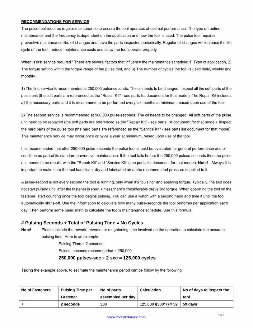
www.mountztorque.com
RECOMMENDATIONS FOR SERVICE
The pulse tool requires regular maintenance to ensure the tool operates at optimal performance. The type of routine
maintenance and the frequency is dependent on the application and how the tool is used. The pulse tool requires
preventive maintenance like oil changes and have the parts inspected periodically. Regular oil changes will increase the life
cycle of the tool, reduce maintenance costs and allow the tool operate properly.
When is first service required? There are several factors that influence the maintenance schedule: 1: Type of application, 2)
The torque setting within the torque range of the pulse tool, and 3) The number of cycles the tool is used daily, weekly and
monthly.
1) The first service is recommended at 250,000 pulse-seconds. The oil needs to be changed. Inspect all the soft parts of the
pulse unit (the soft parts are referenced as the "Repair Kit" - see parts list document for that model). The Repair Kit includes
all the necessary parts and it is recommend to be performed every six months at minimum, based upon use of the tool.
2) The second service is recommended at 500,000 pulse-seconds. The oil needs to be changed. All soft parts of the pulse
unit need to be replaced (the soft parts are referenced as the "Repair Kit" - see parts list document for that model). Inspect
the hard parts of the pulse tool (the hard parts are referenced as the "Service Kit" - see parts list document for that model).
This maintenance service may occur once or twice a year at minimum, based upon use of the tool.
It is recommended that after 250,000 pulse-seconds the pulse tool should be evaluated for general performance and oil
condition as part of its standard preventive maintenance. If the tool fails before the 250,000 pulses-seconds then the pulse
unit needs to be rebuilt, with the "Repair Kit" and "Service Kit" (see parts list document for that model). Note! Always it is
important to make sure the tool has clean, dry and lubricated air at the recommended pressure supplied to it.
A pulse-second is not every second the tool is running, only when it’s "pulsing" and applying torque. Typically, the tool does
not start pulsing until after the fastener is snug, unless there’s considerable prevailing torque. When operating the tool on the
fastener, start counting once the tool begins pulsing. You can use a watch with a second hand and time it until the tool
automatically shuts-off. Use the information to calculate how many pulse-seconds the tool performs per application each
day. Then perform some basic math to calculate the tool’s maintenance schedule. Use this formula.
# Pulsing Seconds ÷ Total of Pulsing Time = No Cycles
Note! Please include the rework, reverse, or retightening time involved on the operation to calculate the accurate
pulsing time. Here is an example:
Pulsing Time = 2 seconds
Pulses- seconds recommended = 250,000
250,000 pulses-sec ÷ 2 sec = 125,000 cycles
Taking the example above, to estimate the maintenance period can be follow by the following
No of Fasteners Pulsing Time per
Fastener
No of parts
assembled per day
Calculation No of days to inspect the
tool
7 2 seconds 300 125,000 /(300*7) = 59 59 days
160
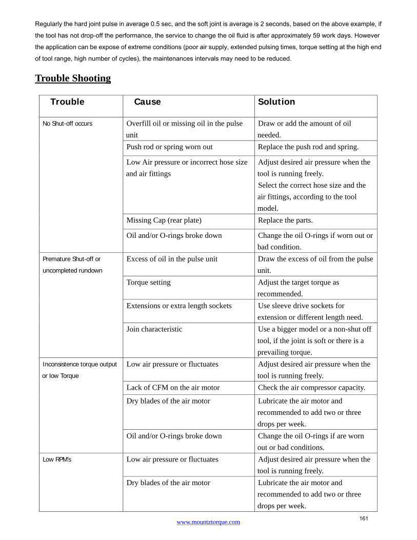
www.mountztorque.com
Regularly the hard joint pulse in average 0.5 sec, and the soft joint is average is 2 seconds, based on the above example, if
the tool has not drop-off the performance, the service to change the oil fluid is after approximately 59 work days. However
the application can be expose of extreme conditions (poor air supply, extended pulsing times, torque setting at the high end
of tool range, high number of cycles), the maintenances intervals may need to be reduced.
Trouble Shooting
Trouble Cause Solution
No Shut-off occurs
Overfill oil or missing oil in the pulse
unit
Draw or add the amount of oil
needed.
Push rod or spring worn out Replace the push rod and spring.
Low Air pressure or incorrect hose size
and air fittings
Adjust desired air pressure when the
tool is running freely.
Select the correct hose size and the
air fittings, according to the tool
model.
Missing Cap (rear plate) Replace the parts.
Oil and/or O-rings broke down Change the oil O-rings if worn out or
bad condition.
Premature Shut-off or
uncompleted rundown
Excess of oil in the pulse unit Draw the excess of oil from the pulse
unit.
Torque setting Adjust the target torque as
recommended.
Extensions or extra length sockets Use sleeve drive sockets for
extension or different length need.
Join characteristic Use a bigger model or a non-shut off
tool, if the joint is soft or there is a
prevailing torque.
Inconsistence torque output
or low Torque
Low air pressure or fluctuates Adjust desired air pressure when the
tool is running freely.
Lack of CFM on the air motor Check the air compressor capacity.
Dry blades of the air motor Lubricate the air motor and
recommended to add two or three
drops per week.
Oil and/or O-rings broke down Change the oil O-rings if are worn
out or bad conditions.
Low RPM’s
Low air pressure or fluctuates Adjust desired air pressure when the
tool is running freely.
Dry blades of the air motor Lubricate the air motor and
recommended to add two or three
drops per week.
161

www.mountztorque.com
Service Centers
Corporate Headquarters & Service Center
1080 North 11th Street, San Jose, CA 95112 Phone: (800) 456-1828 Fax: (408) 292-2733 Distribution & Service Center 19051 Underwood Road, Foley, AL 36535 Phone: (251) 943-4125 Fax: (251) 943-4979 www.mountztorque.com [email protected]
Mr. Metric (a Mountz company) is the leading metric fastener specialist in North America. Well
regarded as experts in metric. Mr. Metric is known for hard to find metric items at competitive prices.
www.mrmetric.com
162
Related Documents