Edition 12/2014 HMI Components Characteristics The compact Series 56 is especially suited for: ■ Front mounting ■ Rear mounting ■ Glass mounting It is characterised by a large ring illumination and an excellent tactile feel. Functions The Series 56 incorporates the following functions: ■ Indicator ■ Pushbutton ■ Illuminated pushbutton ■ Lever switch ■ Sound module ■ Flashing warning beacon Market segments The EAO Series 56 is especially suited for applications in the segments: ■ Public transportation ■ Building technology Series 56 Please refer to the EAO website to obtain detailed information regarding this series www.products.eao.com Configure a product to your exact needs and request a quotation.

Welcome message from author
This document is posted to help you gain knowledge. Please leave a comment to let me know what you think about it! Share it to your friends and learn new things together.
Transcript

Edition 12/2014 HMI Components
CharacteristicsThe compact Series 56 is especially suited for:
■ Front mounting ■ Rear mounting ■ Glass mounting
It is characterised by a large ring illumination and an excellent tactile feel.
FunctionsThe Series 56 incorporates the following functions:
■ Indicator ■ Pushbutton ■ Illuminated pushbutton ■ Lever switch ■ Sound module ■ Flashing warning beacon
Market segmentsThe EAO Series 56 is especially suited for applications in the segments:
■ Public transportation ■ Building technology
Series 56
Please refer to the EAO website to obtain detailed information regarding this series www.products.eao.comConfi gure a product to your exact needs and request a quotation.


3
Content
Overview
Front mounting
Single side indicator 4
Single side pushbutton 6
Lever switch 8
Multi-Tone Sound Module 9
Flashing Warning Beacon 10
Rear mounting
Single side indicator 13
Single side pushbutton 15
Multi-Tone Sound Module 17
Glass mounting
Single side pushbutton 19
Double side pushbutton 21
Multi-Tone Sound Module 23
Accessories 25
Drawings 36
Technical data 38
Application guidelines 48
Index 52
56

4
Additional Information
• Please fill in the form and forward it to your local EAO partner by e-mail or fax. The electronic form is available at http://www.eao.com/offer56
Front mounting
10
17.58
11
17.58
5 max.
2
13
Ø43
KabelØ5.8
12.5
Single side indicator
Front cap
Plastic colourless flush Plastic colourless raised Plastic colourless half round
Marking (Text or symbol)
without marking
with marking 1 line 2 line 3 line symbol
Example:
Open
Example:
Doorclose
Example:
Doorout oforder
Illumination
LED green LED red LED yellow LED white LED blue
Supply voltage illumination
24 VDC 110 VDC
Tolerance +25 % … –30 %
Equipment consisting of
Front bezel
Switching unit
Sealing
Page 25
The preview is based on a sample product. This can differ from your current configuration.
Dimensions [mm] [mm]
Mounting cut-outs [mm]
88 min.112 min.
roundsquare
88 m
in.
112
min
.
Cable exit rightleft
M4 Tap hole3x
42+
1.4
0
65
Each part listed below includes all the black compo-nents shown in the 3D-drawing.
To obtain a complete unit, please select the red com-ponents from the pages shown.
56

5
Front mounting
Cable exit
cable exit right cable exit left
Cable length
A = 200 mm A = 500 mm A = 1000 mm A = 1500 mm ________ mm
Cable and Connector type
Cable Connector
2 x 0.24 mm² core end-sleeves
AMP Connector Mate-N-Lok (Wiring diagram 2)
DEUTSCH connector (Wiring diagram 2)
AMP Connector 2.8 x 0.8 (Wiring diagram 1)
AMP Connector 6.3 x 0.8 (Wiring diagram 2)
Housing
housing D73 (standard) housing reworked 50 x 50 mm housing reworked 68.5 x 50 mm
The drawings you will find from page 36
The component layout No. 1 you will find from page 36
0 V2 bl
+ VDC3 rt
0 V3 bl
+ VDC2 rt
Wiring diagram 1 Wiring diagram 2
56
6
Additional Information
• Please fill in the form and forward it to your local EAO partner by e-mail or fax. The electronic form is available at http://www.eao.com/offer56
Front mounting
Single side pushbutton
Lens
flush, plastic flush, aluminium raised, aluminium
green RAL 6024 naturel naturel
red RAL 3020 green green
blue RAL 5017 red red
yellow RAL 1023 blue blue
grey RAL 7040 yellow yellow
black RAL 9017 black black
orange RAL 2003
Lens marking
without symbol
with symbol aluminium, raised (milled)
Symbol-No. 00.835
Symbol-No. 00.836
Symbol-No. 00.868
Symbol-No. 00.869
Symbol-No. 40089
Symbol-No. 60523
with symbol aluminium, flat (engraved / lasered)
with symbol plastic, flat (engraved / lasered)
Symbol-No. 00.835
Symbol-No. 00.836
Symbol-No. 00.868
Symbol-No. 00.869
Symbol-No. 40089
Symbol-No. 60523
Symbol colour black white
Illumination
without illumination
with illumination 8 green 8 red 8 blue 8 yellow 8 green / 2 red 8 red / 2 green
Supply voltage illumination
24 VDC 36 VDC 48 VDC 72 VDC 110 VDC
Tolerance +25 % … –30 %
Equipment consisting of
Front bezel
Switching unit
Sealing
Page 25
The preview is based on a sample product. This can differ from your current configuration.
Dimensions [mm]
Mounting cut-outs [mm]
5 max.
13
CableØ5.8
3
8 17.5
12.5
Ø43
LE
D
Ø34
88 min.112 min.
roundsquare
88 m
in.
112
min
.
Cable exit rightleft
M4 Tap hole3x
42+
1.4
0
65
Each part listed below includes all the black compo-nents shown in the 3D-drawing.
To obtain a complete unit, please select the red com-ponents from the pages shown.
56

7
Front mounting
Cable exit
cable exit right cable exit left
Cable length
A = 200 mm A = 500 mm A = 1000 mm A = 1500 mm ________ mm
Cable and Connector type
Cable Connector
2 x 0.5 mm² (Wiring diagram 5) core end-sleeves
4 x 0.5 mm² (Wiring diagram 1, 2, 3, 4) AMP Connector Mate-N-Lok (Wiring diagram 3, 4)
DEUTSCH connector (Wiring diagram 3, 4)
AMP Connector 2.8 x 0.8 (Wiring diagram 1, 2)
AMP Connector 6.3 x 0.8 (Wiring diagram 3, 4)
Housing
housing D73 (standard) housing reworked 50 x 50 mm housing reworked 68.5 x 50 mm
The drawings you will find from page 36
The component layouts No. 2 and 3 you will find from page 36
max.137 VDC200 mA
+ VDC
0 V
1 ye
3 bn
4 gn
2 wh
1 x 8 LEDs Single side pushbutton
1 x 2 LEDs Single side pushbutton 1 x 8 LEDs Single side pushbutton
1 ye
3 bn
4 gn
2 wh
Wiring diagram 1 Wiring diagram 2
max.137 VDC200 mA
+ VDC
0 V
1 ye
2 bn
4 gn
3 wh
1 x 8 LEDs Single side pushbutton
1 x 2 LEDs Single side pushbutton 1 x 8 LEDs Single side pushbutton
1 ye
2 bn
4 gn
3 wh
Wiring diagram 3 Wiring diagram 4
max.137 VDC200 mA
1 ye
4 gn
Wiring diagram 5
56

8
Lever switch
Equipment consisting of
Lever
Front bezel
Actuator
Sealing
Bayonet flange
Switching element
Page 25
Page 27
The preview is based on a sample product. This can differ from your current configuration.
Dimensions [mm]
Mounting cut-outs [mm]
5 max.
R70
6618
88 min.88
min
. M4 Tap hole3x
42+
1.4
0
65
Additional Information
• Lever aluminium naturel anodized
• Two switching positions
• Switching action: 0-maintain
• 45° switching angle
• Switching element see technical data Series 04
Each part listed below includes all the black compo-nents shown in the 3D-drawing.
To obtain a complete unit, please select the red com-ponents from the pages shown.
Front mounting
Part No. Weight
704.107.1 0.314 kg
Wiring diagram 1
56

9
Multi-Tone Sound Module
Front cap
Plastic black flush Plastic black raised
Front cap marking
without symbol with symbol
Volume adjustment
Manually (3-/5-Tone Sequences Module) Automatically (6-Tone Sequences Module)
Tone sequence
3-tone 5-tone 6-tone
Supply voltage
24 VDC (5-Tone Sequences Module) 16 … 63 VDC (3-/6-Tone Sequences Module) 50 … 143 VDC (3-/6-Tone Sequences Module)
Tolerance ±30 %
Cable exit
cable exit right cable exit left
Cable length
A = 200 mm A = 500 mm A = 1000 mm A = 1500 mm ________ mm
Equipment consisting of
Front bezel
MTSM unit
Sealing
Page 25
The preview is based on a sample product. This can differ from your current configuration.
Dimensions [mm]
Mounting cut-outs [mm]
Additional Information
• The descriptions of the standard tone sequences see «Application guidelines»
• Please fill in the form and forward it to your local EAO partner by e-mail or fax. The electronic form is available at http://www.eao.com/offer56
Front mounting
88 min.112 min.
roundsquare
88 m
in.
112
min
.
Cable exit rightleft
M4 Tap hole3x
42+
1.4
0
65
5 max.
2
13
Ø43
CableØ5.8
10
17.58
12.5
Each part listed below includes all the black compo-nents shown in the 3D-drawing.
To obtain a complete unit, please select the red com-ponents from the pages shown.
56

10
Cable and Connector type
Cable Connector
4 x 0.25 mm² core end-sleeves
4 x 0.5 mm² AMP Connector Mate-N-Lok
6 x 0.5 mm² DEUTSCH connector
AMP Connector 2.8 x 0.8
AMP Connector 6.3 x 0.8
Housing
housing D73 (standard) housing reworked 50 x 50 mm housing reworked 68.5 x 50 mm
The drawings you will find from page 36
The component layouts No. 4 and 5 you will find from page 36
+24VDC
red
blue
yellow
brown
green
white
Tone 1
Tone 2
Tone 3
Volu
me
Tone 4
Tone 5
0 V
5-Tone sequence
brown
green
yellow
white
Volume
0V
green
yellow
VDC
0V
0V
VDC
Tone sequence
1Wire 2
VDC
VDC
3
16 … 63VDC/50 … 143 VDC
3-Tone sequence
Wiring diagram 1 Wiring diagram 2
brown
green
yellow
white0 V
16 … 63 VDC
1
2
3
4
5
6
16 – 63 VDC
0 V
16 – 63 VDC
0 V
16 – 63 VDC
0 V
0V
16 – 63 VDC
16 – 63 VDC
0 V
0 V
16 – 63 VDC
0V
0V
0V
16 – 63 VDC
16 – 63 VDC
16 – 63 VDC
greenTone yellow brown
50 … 143 VDC
1
2
3
4
5
6
50 – 143 VDC
0 V
50 – 143 VDC
0 V
50 – 143 VDC
0 V
0V
50 – 143 VDC
50 – 143 VDC
0 V
0 V
50 – 143 VDC
0V
0V
0V
50 – 143 VDC
50 – 143 VDC
50 – 143 VDC
greenTone yellow brown
6-Tone sequence
Wiring diagram 3
Front mounting56

11
Additional Information
• Please fill in the form and forward it to your local EAO partner by e-mail or fax. The electronic form is available at http://www.eao.com/offer56
Front mounting
5 max.
10
8 17.5
88 min.112 min.
roundsquare
88 m
in.
112
min
.
Cable exit rightleft
M4 Tap hole3x
42+
1.4
0
65
Flashing warning beacon
Front cap
Plastic colourless raised
Illumination
LED white
Supply voltage
24 VDC
Tolerance ±30 %
Cable exit
cable exit right cable exit left
Cable length
A = 200 mm A = 500 mm A = 1000 mm A = 1500 mm ________ mm
Cable and Connector type
Cable Connector
2 x 0.24 mm² core end-sleeves
AMP Connector Mate-N-Lok (Wiring diagram 2)
DEUTSCH connector (Wiring diagram 2)
AMP Connector 2.8 x 0.8 (Wiring diagram 1)
AMP Connector 6.3 x 0.8 (Wiring diagram 2)
Equipment consisting of
Front bezel
Indicator unit
Sealing
Page 25
The preview is based on a sample product. This can differ from your current configuration.
Dimensions [mm]
Mounting cut-outs [mm]
Each part listed below includes all the black compo-nents shown in the 3D-drawing.
To obtain a complete unit, please select the red com-ponents from the pages shown.
56

12
Front mounting
Housing
housing D73 (standard) housing reworked 50 x 50 mm housing reworked 68.5 x 50 mm
The drawings you will find from page 36
The component layout No. 1 you will find from page 36
0 V2 bl
+ VDC3 rd
0 V3 bl
+ VDC2 rd
Wiring diagram 1 Wiring diagram 2

13
Additional Information
• Please fill in the form and forward it to your local EAO partner by e-mail or fax. The electronic form is available at http://www.eao.com/offer56
Rear mounting
Ø 7
512.5
KabelØ5.8
5
25.5
2
3 max.
21
10
5
25.5
11
Ø43
76 min.
76 m
in.
Cable exit rightleft
Stud3xM4x18 min.
6543
.4±
0.1
The preview is based on a sample product. This can differ from your current configuration.
Dimensions [mm]
Each part number listed below includes all the black components shown in the 3D-drawing.
Mounting cut-outs [mm]
Front cap
Plastic colourless flush Plastic colourless raised Plastic colourless half round
Marking (Text or symbol)
without marking
with marking 1 line 2 line 3 line symbol
Example:
Open
Example:
Doorclose
Example:
Doorout oforder
Illumination
LED green LED red LED yellow LED white LED blue
Supply voltage
24 VDC 110 VDC
Tolerance +25 % … –30 %
Equipment consisting of
Sealing
Switching unit
Single side indicator
56

14
Rear mounting
Cable exit
cable exit right cable exit left
Cable length
A = 200 mm A = 500 mm A = 1000 mm A = 1500 mm ________ mm
Cable + Connector type
Cable Connector
2 * 0.24 mm² core end-sleeves
AMP Connector Mate-N-Lok (Wiring diagram 2)
DEUTSCH connector (Wiring diagram 2)
AMP Connector 2.8 x 0.8 (Wiring diagram 1)
AMP Connector 6.3 x 0.8 (Wiring diagram 2)
Housing
housing D73 (standard) housing reworked 50 x 50 mm housing reworked 68.5 x 50 mm
The drawings you will find from page 36
The component layout No. 1 you will find from page 36
0 V2 bl
+ VDC3 rd
0 V3 bl
+ VDC2 rd
Wiring diagram 1 Wiring diagram 2
56

15
Additional Information
• Please fill in the form and forward it to your local EAO partner by e-mail or fax. The electronic form is available at http://www.eao.com/offer56
Rear mounting
5
25.53
Ø 7
512.5
KabelØ5.8
4 max.
21
Ø43
Ø34
76 min.
76 m
in.
Cable exit rightleft
Stud3xM4x18 min.
6543
.4±
0.1
Lens
flush, plastic flush, aluminium raised, aluminium
green RAL 6024 naturel naturel
red RAL 3020 green green
blue RAL 5017 red red
yellow RAL 1023 blue blue
light-grey RAL 7040 yellow yellow
black RAL 9017 black black
orange RAL 2003
Lens marking
without symbol
with symbol aluminium, raised (milled)
Symbol-No. 00.835
Symbol-No. 00.836
Symbol-No. 00.868
Symbol-No. 00.869
Symbol-No. 40089
Symbol-No. 60523
with symbol aluminium, flat (engraved / lasered)
with symbol plastic, flat (engraved / lasered)
Symbol-No. 00.835
Symbol-No. 00.836
Symbol-No. 00.868
Symbol-No. 00.869
Symbol-No. 40089
Symbol-No. 60523
Symbol colour black white
Illumination
without illumination
with illumination 8 green 8 red 8 blue 8 yellow 8 green / 2 red 8 red / 2 green
Supply voltage
24 VDC 36 VDC 48 VDC 72 VDC 110 VDC
Tolerance +25 % … –30 %
Each part listed below includes all the black compo-nents shown in the 3D-drawing.
Equipment consisting of
Sealing
Switching unit
The preview is based on a sample product. This can differ from your current configuration.
Dimensions [mm]
Mounting cut-outs [mm]
56Single side pushbutton

16
Rear mounting
Cable exit
cable exit right cable exit left
Cable length
A = 200 mm A = 500 mm A = 1000 mm A = 1500 mm ________ mm
Cable + Connector type
Cable Connector
2 x 0.5 mm² (Wiring diagram 5) core end-sleeves
4 x 0.5 mm² (Wiring diagram 1, 2, 3, 4) AMP Connector Mate-N-Lok (Wiring diagram 3, 4)
DEUTSCH connector (Wiring diagram 3, 4)
AMP Connector 2.8 x 0.8 (Wiring diagram 1, 2)
AMP Connector 6.3 x 0.8 (Wiring diagram 3, 4)
Housing
housing D73 (standard) housing reworked 50 x 50 mm housing reworked 68.5 x 50 mm
The drawings you will find from page 36
The component layout No. 2 you will find from page 36
max.137 VDC200 mA
+ VDC
0 V
1 ye
3 bn
4 gn
2 wh
1 x 8 LEDs Single side pushbutton
1 x 2 LEDs Single side pushbutton 1 x 8 LEDs Single side pushbutton
1 ye
3 bn
4 gn
2 wh
Wiring diagram 1 Wiring diagram 2
max.137 VDC200 mA
+ VDC
0 V
1 ye
2 bn
4 gn
3 wh
1 x 8 LEDs Single side pushbutton
1 x 2 LEDs Single side pushbutton 1 x 8 LEDs Single side pushbutton
1 ye
2 bn
4 gn
3 wh
Wiring diagram 3 Wiring diagram 4
max.137 VDC200 mA
1 ye
4 gn
Wiring diagram 5
56

17
Additional Information
• Please fill in the form and forward it to your local EAO partner by e-mail or fax. The electronic form is available at http://www.eao.com/offer56
Front cap
Plastic black flush Plastic black raised
Front cap marking
without symbol with symbol
Volume adjustment
Manually (3-/5-Tone Sequences Module) Automatically (6-Tone Sequences Module)
Tone sequence
3-tone 5-tone 6-tone
Supply voltage
24 VDC (5-Tone Sequences Module) 16 … 63 VDC (3-/6-Tone Sequences Module) 50 … 143 VDC (3-/6-Tone Sequences Module)
Tolerance ±30 %
Cable exit
cable exit right cable exit left
Cable length
A = 200 mm A = 500 mm A = 1000 mm A = 1500 mm ________ mm
Rear mounting
Ø 7
512.5
CableØ5.8
525.5
2
3 max.
21
10
Ø43
76 min.
76 m
in.
Cable exit rightleft
Stud3xM4x18 min.
6543
.4±
0.1
Equipment consisting of
Sealing
MTSM unit
Each part listed below includes all the black compo-nents shown in the 3D-drawing.
Dimensions [mm]
Mounting cut-outs [mm]
The preview is based on a sample product. This can differ from your current configuration.
56Multi-Tone Sound Module

18
Rear mounting
Cable + Connector type
Cable Connector
4 x 0.25 mm² core end-sleeves
4 x 0.5 mm² AMP Connector Mate-N-Lok
6 x 0.5 mm² DEUTSCH connector
AMP Connector 2.8 x 0.8
AMP Connector 6.3 x 0.8
Housing
housing D73 (standard) housing reworked 50 x 50 mm housing reworked 68.5 x 50 mm
The drawings you will find from page 36
The component layouts No. 4, 5 and 6 you will find from page 36
+24VDC
red
blue
yellow
brown
green
white
Tone 1
Tone 2
Tone 3
Volu
me
Tone 4
Tone 5
0 V
5-Tone sequence
brown
green
yellow
white
Volume
0V
green
yellow
VDC
0V
0V
VDC
Tone sequence
1Wire 2
VDC
VDC
3
16 … 63VDC/50 … 143 VDC
3-Tone sequence
Wiring diagram 1 Wiring diagram 2
brown
green
yellow
white0 V
16 … 63 VDC
1
2
3
4
5
6
16 – 63 VDC
0 V
16 – 63 VDC
0 V
16 – 63 VDC
0 V
0V
16 – 63 VDC
16 – 63 VDC
0 V
0 V
16 – 63 VDC
0V
0V
0V
16 – 63 VDC
16 – 63 VDC
16 – 63 VDC
greenTone yellow brown
50 … 143 VDC
1
2
3
4
5
6
50 – 143 VDC
0 V
50 – 143 VDC
0 V
50 – 143 VDC
0 V
0V
50 – 143 VDC
50 – 143 VDC
0 V
0 V
50 – 143 VDC
0V
0V
0V
50 – 143 VDC
50 – 143 VDC
50 – 143 VDC
greenTone yellow brown
6-Tone sequence
Wiring diagram 3
56

19
Glass mounting
DrainageLens Ø34LED Ø43
8
16.53
4 ... 6
Cable coverdetachable
CableØ5.8
5 max.
88 m
in.
40 x
26
Glass 4 ... 6
Cut-out 11.5 x 18 max.
45+3 0
62.5+1
0
Use adhesive bezel cover when cable-inlet dimensions >11.5 x 18 mm
Additional Information
• Front bezel Ø 87 mm
• Cable exit left
• Housing D73 (standard)
• Other cable cover are available
• Please fill in the form and forward it to your local EAO partner by e-mail or fax. The electronic form is available at http://www.eao.com/offer56
The preview is based on a sample product. This can differ from your current configuration.
Dimensions [mm]
Mounting cut-outs [mm]
Lens
flush, plastic flush, aluminium raised, aluminium
green RAL 6024 naturel naturel
red RAL 3020 green green
blue RAL 5017 red red
yellow RAL 1023 blue blue
light-grey RAL 7040 yellow yellow
black RAL 9017 black black
orange RAL 2003
Lens marking
without symbol
with symbol aluminium, raised (milled)
Symbol-No. 00.835
Symbol-No. 00.836
Symbol-No. 00.868
Symbol-No. 00.869
Symbol-No. 40089
Symbol-No. 60523
with symbol aluminium, flat (engraved / lasered)
with symbol plastic, flat (engraved / lasered)
Symbol-No. 00.835
Symbol-No. 00.836
Symbol-No. 00.868
Symbol-No. 00.869
Symbol-No. 40089
Symbol-No. 60523
Symbol colour black white
Illumination
without illumination
with illumination 8 green 8 red 8 blue 8 yellow 8 green / 2 red 8 red / 2 green
Supply voltage
24 VDC 36 VDC 48 VDC 72 VDC 110 VDC
Tolerance +25 % … –30 %
Each part listed below includes all the black compo-nents shown in the 3D-drawing.
To obtain a complete unit, please select the red com-ponents from the pages shown.
Equipment consisting of
Front bezel
Switching unit
Cable cover
Cover
Page 25
Single side pushbutton
56

20
Glass mounting
Cable length
A = 200 mm A = 500 mm A = 1000 mm A = 1500 mm ________ mm
Cable + Connector type
Cable Connector
2 x 0.5 mm² (without illumination, wiring diagram 5) core end-sleeves
4 x 0.5 mm² (Wiring diagram 1, 2, 3, 4) AMP Connector Mate-N-Lok (Wiring diagram 3, 4)
DEUTSCH connector (Wiring diagram 3, 4)
AMP Connector 2.8 x 0.8 (Wiring diagram 1, 2)
AMP Connector 6.3 x 0.8 (Wiring diagram 3, 4)
The component layouts No. 2 and 3 you will find from page 36
max.137 VDC200 mA
+ VDC
0 V
1 ye
3 bn
4 gn
2 wh
1 x 8 LEDs Single side pushbutton
1 x 2 LEDs Single side pushbutton 1 x 8 LEDs Single side pushbutton
1 ye
3 bn
4 gn
2 wh
Wiring diagram 1 Wiring diagram 2
max.137 VDC200 mA
+ VDC
0 V
1 ye
2 bn
4 gn
3 wh
1 x 8 LEDs Single side pushbutton
1 x 2 LEDs Single side pushbutton 1 x 8 LEDs Single side pushbutton
1 ye
2 bn
4 gn
3 wh
Wiring diagram 3 Wiring diagram 4
max.137 VDC200 mA
1 ye
4 gn
Wiring diagram 5
56

21
Glass mounting
88 m
in.
40 x
26
Glass 4 ... 6
Cut-out 11.5 x 18 max.
45+3 0
62.5+1
0
Use adhesive bezel cover when cable-inlet dimensions >11.5 x 18 mm
DrainageLens Ø34LED Ø43
253
8
4 ... 6
Cable coverdetachable
CableØ5.8
5 max.
Equipment consisting of
Front bezel
Switching unit
Cable cover
Flange
Front bezel internal
Page 25
Page 25
Lens
flush, plastic flush, aluminium raised, aluminium
green RAL 6024 naturel naturel
red RAL 3020 green green
blue RAL 5017 red red
yellow RAL 1023 blue blue
light-grey RAL 7040 yellow yellow
black RAL 9017 black black
orange RAL 2003
Lens marking
without symbol
with symbol aluminium, raised (milled)
Symbol-No. 00.835
Symbol-No. 00.836
Symbol-No. 00.868
Symbol-No. 00.869
Symbol-No. 40089
Symbol-No. 60523
with symbol aluminium, flat (engraved / lasered)
with symbol plastic, flat (engraved / lasered)
Symbol-No. 00.835
Symbol-No. 00.836
Symbol-No. 00.868
Symbol-No. 00.869
Symbol-No. 40089
Symbol-No. 60523
Symbol colour black white
Each part listed below includes all the black compo-nents shown in the 3D-drawing.
To obtain a complete unit, please select the red com-ponents from the pages shown.
The preview is based on a sample product. This can differ from your current configuration.
Dimensions [mm]
Mounting cut-outs [mm]
Product features
• Front bezel Ø 87 mm
• Cable exit left
• Housing D73 (standard)
• Please fill in the form and forward it to your local EAO partner by e-mail or fax. The electronic form is available at http://www.eao.com/offer56
56Double side pushbutton

22
Glass mounting
Illumination
without illumination
with illumination 16 green 16 red 8 red / 2 green 8 green / 2 red
Supply voltage illumination
24 VDC 110 VDC
Tolerance +25 % … –30 %
Cable length
A = 200 mm A = 500 mm A = 1000 mm A = 1500 mm ________ mm
Cable + Connector type
Cable Connector
2 x 0.5 mm² (without illumination, wiring diagram 1, 2) core end-sleeves
4 x 0.5 mm² (Wiring diagram 1, 2, 3, 4) AMP Connector Mate-N-Lok (Wiring diagram 3, 4)
DEUTSCH connector (Wiring diagram 3, 4)
AMP Connector 2.8 x 0.8 (Wiring diagram 1, 2)
AMP Connector 6.3 x 0.8 (Wiring diagram 3, 4)
The component layouts No. 2 and 3 you will find from page 36
max.137 VDC200 mA
+ VDC
0 V
1 ye
3 bn
4 gn
2 wh
2 x 8 LEDs Double side pushbutton
2 x 2 LEDs Double side pushbutton 2 x 8 LEDs Double side pushbutton
1 ye
3 bn
4 gn
2 wh
Wiring diagram 1 Wiring diagram 2
max.137 VDC200 mA
+ VDC
0 V
1 ye
2 bn
4 gn
3 wh
2 x 8 LEDs Double side pushbutton
2 x 2 LEDs Double side pushbutton 2 x 8 LEDs Double side pushbutton
Wiring diagram 3 Wiring diagram 4
max.137 VDC200 mA
1 ye
4 gn
Wiring diagram 5
56
23
Glass mounting
8
16.53
4 ... 6
Cable coverdetachable
CableØ5.8
5 max.
Ø43
88 m
in.
40 x
26
Glass 4 ... 6
Cut-out 11.5 x 18 max.
45+3 0
62.5+1
0
Use adhesive bezel cover when cable-inlet dimensions >11.5 x 18 mm
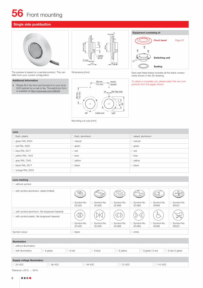
The preview is based on a sample product. This can differ from your current configuration.
Dimensions [mm]
Mounting cut-outs [mm]
Equipment consisting of
Front bezel
MTSM unit
Cable cover
Cover
Page 25
Each part listed below includes all the black compo-nents shown in the 3D-drawing.
To obtain a complete unit, please select the red com-ponents from the pages shown.
Front cap
Plastic black flush Plastic black raised
Front cap marking
without symbol with symbol
Volume adjustment
Manually (3-/5-Tone Sequences Module) Automatically (6-Tone Sequences Module)
Tone sequence
3-tone 5-tone 6-tone
Supply voltage
24 VDC (5-Tone Sequences Module) 16 … 63 VDC (3-/6-Tone Sequences Module) 50 … 143 VDC (3-/6-Tone Sequences Module)
Tolerance ±30 %
Cable exit
cable exit right cable exit left
Cable length
A = 200 mm A = 500 mm A = 1000 mm A = 1500 mm ________ mm
Cable + Connector type
Cable Connector
4 * 0.5 mm² core end-sleeves
AMP Connector Mate-N-Lok
DEUTSCH connector
AMP Connector 2.8 x 0.8
AMP Connector 6.3 x 0.8
The component layout No. 5 you will find from page 36
Product features
• Front bezel Ø 87 mm
• Cable exit left
• Housing D73 (standard)
• Please fill in the form and forward it to your local EAO partner by e-mail or fax. The electronic form is available at http://www.eao.com/offer56
Multi-Tone Sound Module
56

24
Glass mounting
+24VDC
red
blue
yellow
brown
green
white
Tone 1
Tone 2
Tone 3
Volu
me
Tone 4
Tone 5
0 V
5-Tone sequence
brown
green
yellow
white
Volume
0V
green
yellow
VDC
0V
0V
VDC
Tone sequence
1Wire 2
VDC
VDC
3
16 … 63VDC/50 … 143 VDC
3-Tone sequence
Wiring diagram 1 Wiring diagram 2
brown
green
yellow
white0 V
16 … 63 VDC
1
2
3
4
5
6
16 – 63 VDC
0 V
16 – 63 VDC
0 V
16 – 63 VDC
0 V
0V
16 – 63 VDC
16 – 63 VDC
0 V
0 V
16 – 63 VDC
0V
0V
0V
16 – 63 VDC
16 – 63 VDC
16 – 63 VDC
greenTone yellow brown
50 … 143 VDC
1
2
3
4
5
6
50 – 143 VDC
0 V
50 – 143 VDC
0 V
50 – 143 VDC
0 V
0V
50 – 143 VDC
50 – 143 VDC
0 V
0 V
50 – 143 VDC
0V
0V
0V
50 – 143 VDC
50 – 143 VDC
50 – 143 VDC
greenTone yellow brown
6-Tone sequence
Wiring diagram 3
56

25
Accessories
Front
Front bezel
Additional Information
• Special colours for front bezel on request
Product attribute Colour Front bezel Part No. Weight
Front bezel, front dimension 87 x 87 mmFor single side indicator and single side pushbutton, front mounting
RAL 3020 Plastic red 56-2200 0.026 kg
RAL 1023 Plastic yellow 56-2400 0.026 kg
RAL 6024 Plastic green 56-2500 0.026 kg
RAL 5017 Plastic blue 56-2600 0.026 kg
Metal matt chrome 56-4600 0.085 kg
Front bezel, front dimension Ø 87 mmFor single side indicator and single side pushbutton; double side push-button external
RAL 9017 Pastic black 56-1000 0.018 kg
RAL 3020 Plastic red 56-1200 0.018 kg
RAL 2003 Plastic orange 56-1300 0.018 kg
RAL 1023 Plastic yellow 56-1400 0.018 kg
RAL 6024 Plastic green 56-1500 0.018 kg
RAL 5017 Plastic blue 56-1600 0.018 kg
RAL 7043 Plastic darkgrey 56-1800 0.018 kg
RAL 7040 Plastic lightgrey 56-1800A 0.018 kg
Metal matt chrome 56-3600 0.07 kg
Front bezel internal
Additional Information
• For double side pushbutton
Dimension Colour Front bezel Part No. Weight
Front bezel internalØ 87 mm RAL 3020 Plastic red 56-5200 0.09 kg
RAL 2003 Plastic orange 56-5300 0.09 kg
RAL 1023 Plastic yellow 56-5400 0.09 kg
RAL 6024 Plastic green 56-5500 0.09 kg
RAL 5017 Plastic blue 56-5600 0.09 kg
RAL 7043 Plastic darkgrey 56-5800 0.09 kg
RAL 7040 Plastic lightgrey 56-5800A 0.09 kg
Metal matt chrome 56-7600 0.115 kg
56

26
Accessories
Front bezel for blind and visually impaired persons round
Additional Information
• For single side pushbutton, double side pushbut-ton external
• Special colours for front bezel on request
Marking Colour Front bezel Part No. Weight
Front bezel for blind and visually impaired persons round, front dimension Ø 87 mmBraille + Open RAL 3020 Plastic red 56-1291 0.018 kg
RAL 2003 Plastic orange 56-1391 0.018 kg
Braille + Close RAL 2003 Plastic orange 56-1392 0.018 kg
Braille + Open RAL 1023 Plastic yellow 56-1491 0.018 kg
Braille + Close RAL 1023 Plastic yellow 56-1492 0.018 kg
Front bezel for blind and visually impaired persons triangular
Additional Information
• For single side pushbutton
• SOS character height 15 mm, black printed according TSI/PRM and braille SOS as per DIN 32976
• Special colours for front bezel on request
Marking Colour Front bezel Part No. Weight
Front bezel for blind and visually impaired persons triangular, front dimension 106 x 101 mmBraille + SOS RAL 1023 Plastic yellow 56-8000.A 0.029 kg
RAL 1028 Plastic melon yellow 56-8000.1A 0.029 kg
RAL 3020 Plastic red 56-8000.3A 0.029 kg
RAL 6020 Plastic green 56-8000.5A 0.029 kg
56

27
Accessories
32 37
23
44
26.5 25 25
29
40 40PIT
X
P3 P4
Switching element
Additional Information
• For the third switching element the terminal mar-king insert is to be ordered separately
Dimensions [mm]PIT = Push-in terminal, P3 = Plug-in terminal 6.3 x 0.8 mm, P4 = Double plug-in terminal 6.3 x 0.8 mm, X = Screw terminal
Sw
itch
ing
vo
ltag
e
Sw
itch
ing
cu
rren
t
Switching system Contacts Contact material Terminal Part No. Wir
ing
d
iag
ram
Weight
Switching element250 VAC 6 A Snap-action switching
element1 NO Gold Push-in Terminal 704.907.1 3 0.02 kg
1 NC Gold Push-in Terminal 704.907.2 1 0.02 kg
2 NO Gold Push-in Terminal 704.907.3 5 0.027 kg
2 NC Gold Push-in Terminal 704.907.4 4 0.027 kg
1 NC + 1 NO Gold Push-in Terminal 704.907.5 2 0.027 kg
1 NO Silver Push-in Terminal 704.908.1 3 0.02 kg
1 NC Silver Push-in Terminal 704.908.2 1 0.02 kg
2 NO Silver Push-in Terminal 704.908.3 5 0.027 kg
2 NC Silver Push-in Terminal 704.908.4 4 0.027 kg
1 NC + 1 NO Silver Push-in Terminal 704.908.5 2 0.027 kg
Rear side
56

28
AccessoriesS
wit
chin
g
volt
age
Sw
itch
ing
cu
rren
t
Switching system Contacts Contact material Terminal Part No. Wir
ing
d
iag
ram
Weight
Switching element250 VAC 6 A Slow-make switching
element1 NO Gold Push-in Terminal 704.917.1 3 0.019 kg
1 NC Gold Push-in Terminal 704.917.2 1 0.019 kg
2 NO Gold Push-in Terminal 704.917.3 5 0.026 kg
2 NC Gold Push-in Terminal 704.917.4 4 0.019 kg
1 NC + 1 NO Gold Push-in Terminal 704.917.5 2 0.026 kg
1 NO Silver Push-in Terminal 704.918.1 3 0.019 kg
1 NC Silver Push-in Terminal 704.918.2 1 0.019 kg
2 NO Silver Push-in Terminal 704.918.3 5 0.026 kg
2 NC Silver Push-in Terminal 704.918.4 4 0.019 kg
1 NC + 1 NO Silver Push-in Terminal 704.918.5 2 0.026 kg
Switching element500 VAC 10 A Snap-action switching
element1 NO Silver Plug 6.3 x 0.8 mm 704.905.1 3 0.021 kg
1 NC Silver Plug 6.3 x 0.8 mm 704.905.2 1 0.021 kg
2 NO Silver Plug 6.3 x 0.8 mm 704.905.3 5 0.028 kg
2 NC Silver Plug 6.3 x 0.8 mm 704.905.4 4 0.028 kg
1 NC + 1 NO Silver Plug 6.3 x 0.8 mm 704.905.5 2 0.028 kg
Switching element500 VAC 10 A Slow-make switching
element1 NO Silver Plug 6.3 x 0.8 mm 704.915.1 3 0.021 kg
1 NC Silver Plug 6.3 x 0.8 mm 704.915.2 1 0.021 kg
2 NO Silver Plug 6.3 x 0.8 mm 704.915.3 5 0.028 kg
2 NC Silver Plug 6.3 x 0.8 mm 704.915.4 4 0.028 kg
1 NC + 1 NO Silver Plug 6.3 x 0.8 mm 704.915.5 2 0.028 kg
Switching element500 VAC 10 A Snap-action switching
element1 NO Gold Double plug
6.3 x 0.8 mm704.901.1/D 3 0.026 kg
1 NC Gold Double plug 6.3 x 0.8 mm
704.901.2/D 1 0.026 kg
2 NO Gold Double plug 6.3 x 0.8 mm
704.901.3/D 5 0.033 kg
2 NC Gold Double plug 6.3 x 0.8 mm
704.901.4/D 4 0.033 kg
56

29
AccessoriesS
wit
chin
g
volt
age
Sw
itch
ing
cu
rren
t
Switching system Contacts Contact material Terminal Part No. Wir
ing
d
iag
ram
Weight
500 VAC 10 A Snap-action switching element
1 NC + 1 NO Gold Double plug 6.3 x 0.8 mm
704.901.5/D 2 0.033 kg
1 NO Silver Double plug 6.3 x 0.8 mm
704.905.1/D 3 0.026 kg
1 NC Silver Double plug 6.3 x 0.8 mm
704.905.2/D 1 0.026 kg
2 NO Silver Double plug 6.3 x 0.8 mm
704.905.3/D 5 0.033 kg
2 NC Silver Double plug 6.3 x 0.8 mm
704.905.4/D 4 0.033 kg
1 NC + 1 NO Silver Double plug 6.3 x 0.8 mm
704.905.5/D 2 0.033 kg
Switching element500 VAC 10 A Slow-make switching
element1 NO Silver Double plug
6.3 x 0.8 mm704.915.1/D 3 0.025 kg
1 NC Silver Double plug 6.3 x 0.8 mm
704.915.2/D 1 0.025 kg
2 NO Silver Double plug 6.3 x 0.8 mm
704.915.3/D 5 0.032 kg
2 NC Silver Double plug 6.3 x 0.8 mm
704.915.4/D 4 0.032 kg
1 NC + 1 NO Silver Double plug 6.3 x 0.8 mm
704.915.5/D 2 0.032 kg
Switching element500 VAC 10 A Snap-action switching
element1 NO Gold Screw 704.901.1 3 0.021 kg
1 NC Gold Screw 704.901.2 1 0.021 kg
2 NO Gold Screw 704.901.3 5 0.028 kg
2 NC Gold Screw 704.901.4 4 0.028 kg
1 NC + 1 NO Gold Screw 704.901.5 2 0.028 kg
1 NO Silver Screw 704.900.1 3 0.021 kg
1 NC Silver Screw 704.900.2 1 0.021 kg
2 NO Silver Screw 704.900.3 5 0.028 kg
2 NC Silver Screw 704.900.4 4 0.028 kg
1 NC + 1 NO Silver Screw 704.900.5 2 0.028 kg
1 NO Palladium Screw 704.902.1 3 0.021 kg
1 NC Palladium Screw 704.902.2 1 0.021 kg
2 NO Palladium Screw 704.902.3 5 0.028 kg
2 NC Palladium Screw 704.902.4 4 0.028 kg
1 NC + 1 NO Palladium Screw 704.902.5 2 0.028 kg
56

30
Accessories
11
12
13 21
2214
13
14
11
12
21
22
13 23
2414
Wiring diagram 1 Wiring diagram 2 Wiring diagram 3 Wiring diagram 4 Wiring diagram 5
Sw
itch
ing
vo
ltag
e
Sw
itch
ing
cu
rren
t
Switching system Contacts Contact material Terminal Part No. Wir
ing
d
iag
ram
Weight
Switching element500 VAC 10 A Slow-make switching
element1 NO Gold Screw 704.911.1 3 0.021 kg
1 NC Gold Screw 704.911.2 1 0.021 kg
2 NO Gold Screw 704.911.3 5 0.028 kg
2 NC Gold Screw 704.911.4 4 0.028 kg
1 NC + 1 NO Gold Screw 704.911.5 2 0.028 kg
1 NO Silver Screw 704.910.1 3 0.021 kg
1 NC Silver Screw 704.910.2 1 0.021 kg
2 NO Silver Screw 704.910.3 5 0.028 kg
2 NC Silver Screw 704.910.4 4 0.028 kg
1 NC + 1 NO Silver Screw 704.910.5 2 0.028 kg
1 NO Palladium Screw 704.912.1 3 0.021 kg
1 NC Palladium Screw 704.912.2 1 0.021 kg
2 NO Palladium Screw 704.912.3 5 0.028 kg
2 NC Palladium Screw 704.912.4 4 0.028 kg
1 NC + 1 NO Palladium Screw 704.912.5 2 0.028 kg
Contacts: NC = Normally closed, NO = Normally open
56

31
Accessories
32 372329
11
12
13 21
2214
13
14
11
12
21
22
13 23
2414
Wiring diagram 1 Wiring diagram 2 Wiring diagram 3 Wiring diagram 4 Wiring diagram 5
Switching element ring cable lug
Dimensions [mm]
Sw
itch
ing
vo
ltag
e
Sw
itch
ing
cu
rren
t
Switching system Contacts Contact material Terminal Part No. Wir
ing
d
iag
ram
Weight
Switching element for ring cable shoe500 VAC 10 A Snap-action switching element 1 NO Silver Screw 704.900.1B 3 0.021 kg
1 NC Silver Screw 704.900.2B 1 0.021 kg
2 NO Silver Screw 704.900.3B 5 0.028 kg
2 NC Silver Screw 704.900.4B 4 0.028 kg
1 NC + 1 NO Silver Screw 704.900.5B 2 0.028 kg
Switching element for ring cable shoe500 VAC 10 A Slow-make switching element 1 NO Gold Screw 704.911.1B 3 0.021 kg
1 NC Gold Screw 704.911.2B 1 0.021 kg
2 NO Gold Screw 704.911.3B 5 0.028 kg
2 NC Gold Screw 704.911.4B 4 0.028 kg
1 NC + 1 NO Gold Screw 704.911.5B 2 0.028 kg
1 NO Silver Screw 704.910.1B 3 0.021 kg
1 NC Silver Screw 704.910.2B 1 0.021 kg
2 NO Silver Screw 704.910.3B 5 0.028 kg
2 NC Silver Screw 704.910.4B 4 0.028 kg
1 NC + 1 NO Silver Screw 704.910.5B 2 0.028 kg
Contacts: NC = Normally closed, NO = Normally open
56

32
Accessories
88 m
in.
40 x
26
Glass 4 ... 6
Cut-out 11.5 x 18 max.
45+3 0
62.5+1
0
Use adhesive bezel cover when cable-inlet dimensions >11.5 x 18 mm
Mounting
Cable cover standard
Additional Information
• Additional cable covers are available on request
Mounting cut-outs [mm]
Product attribute Cable cover Part No. Weight
Cable cover standardincluded in standard delivery standard 0° 56-992 0.003 kg
Cable cover standardspecify Part No. in purchase order standard 45° 56-992A 0.005 kg
56

33
Accessories
0º 9º | 10º | 15º | 25º
88 m
in.
24 max
.
Glass 4 ... 6
Cut-out
5 min.
17.5 max.
62.5+1
0
Cable cover funnel
Additional Information
• Specify Part No. in purchase order
pCaution: Funnel shaped cable cover Part No. 56-992B, C, D, E, F are not replacable after first mounting
Dimensions [mm]
Mounting cut-outs [mm]
Cable cover Part No. Weight
Cable cover funnelfunnel 0° 56-992B 0.01 kg
funnel 10° 56-992C 0.01 kg
funnel 15° 56-992D 0.01 kg
funnel 25° 56-992E 0.01 kg
Funnel 9° 56-992F 0.01 kg
Bezel cover
Product attribute Dimension Material Colour Mounting type Part No. Weight
Bezel cover0.8 mm thick 40 x 26 mm Aluminium natural anodized adhesive 56-993 0.005 kg
56

34
Accessories
Part No. Weight
Dismantling tool
57-9901 0.012 kg
Anti-slip mat
Additional Information
• For dismounting of front bezel
• 3 mm dick
Dimension Colour Part No. Weight
Anti-slip mat100 x 100 mm white 56-999 0.033 kg
Dismantling tool
Additional Information
• For front bezel
Product attribute Art.-Nr. Gewicht
Mounting set for rear mountingFor front panel thickness 2 mm 56-991 0.034 kg
Mounting set for rear mountingFor front panel thickness 3 mm 56-991D 0.035 kg
Mounting set for rear mounting
56

35
Accessories
Counterpart set for plug-in housing 2.8 x 0.8 mm
Additional Information
• (set of 10 pieces)
Part No. Weight
Counterpart set for plug-in housing 2.8 x 0.8 mm
56-994 0.012 kg
Counterpart set for plug-in housing 6.3 x 0.8 mm
Additional Information
• (set of 10 pieces)
Part No. Weight
Counterpart set for plug-in housing 6.3 x 0.8 mm
56-995 0.012 kg
Sealing
Part No. Weight
Sealing black, glass mounting56-990 0.004 kg
56

36
Drawings
Drawings
D
Housing D73 (Standard) Housing 50x50 mm Housing 68.5x50 mm
Plug-in terminal2.8 x 0.8 mm
3
2
Standard type
4
2 1
4 3
2 1
3Plug-in terminal2.8 x 0.8 mm
Plug-in terminal6.3 x 0.8 mm
Standard type
Component layout 1 Component layout 2
4 4
11
Plug-in terminal2.8 x 0.8 mm
Plug-in terminal6.3 x 0.8 mm
Standard type
Component layout 3
red
blue
yellow
brown
green
white
(Tone sequence 1)
(Tone sequence 2)
(Tone sequence 3)
(Tone sequence 4)
(Tone sequence 5)
(0V)
Component layout 4
56
37
Drawings
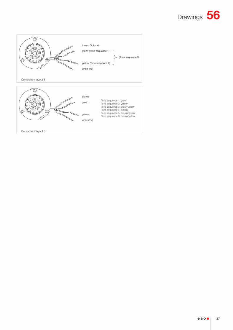
brown (Volume)
green (Tone sequence 1)
(Tone sequence 3)
yellow (Tone sequence 2)
white (0V)
Component layout 5
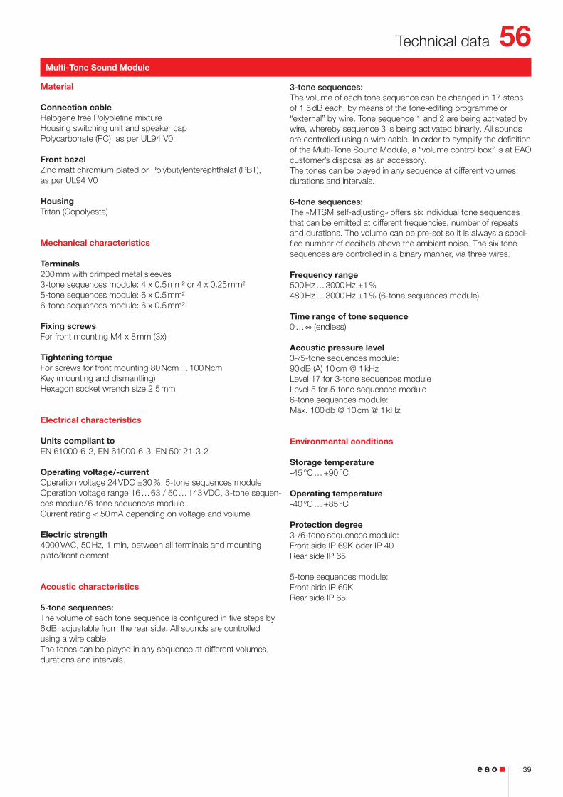
brown
green
yellow
white (0V)
Tone sequence 1: greenTone sequence 2: yellowTone sequence 3: green/yellowTone sequence 4: brownTone sequence 5: brown/greenTone sequence 6: brown/yellow
Component layout 6
56

38
Technical data
Indicator
Material
Connection cableHalogene free Polyolefine mixture
LensPolycarbonate (PC), as per UL94 V0
Front bezelZinc matt chromium plated or Polybutylenterephthalat (PBT), as per UL94 V0
ActuatorPolycarbonate (PC), as per UL94 V0
Mechanical characteristics
TerminalsCable 2-poles with plug-in connection 2.8 x 0.8 mmFlat plug-in housing rectangular, AMP No. 626 057-0
Counterpart to AMP Flat plug-in housing(not part of delivery)Receptacle housing AMP No. 626 056-0Receptacle socket AMP No. 160 655-2
Wire cross-section0.24 mm²
Wire length200 mm with AMP connector 2.8 x 0.8 mm
Fixing screwsFor front mounting M4 x 8 mm
Tightening torqueFor screws for front mounting 80 Ncm … 100 NcmKey (mounting and dismantling)Hexagon socket wrench size 2.5 mm
Electrical characteristics
Illumination15 LED green, red, yellow, white or blueSupply voltage 24, 110 VDCTolerance -30 % … +25 %Current consumption < 50 mALuminosity and wave length variations caused by LED manufactu-ring processes may cause slight differences regarding the illumi-nation
Units compliant toEN 61058-1, EN 50081-1, EN 50082-1, EN 50082-2, EN 50121-3-2, EN 50155
Environmental conditions
Storage temperature-45 °C … +90 °C
Operating temperature-40 °C … +80 °C
Protection degreeFront side IP 67Rear side IP 65
Climate resistanceDamp heat, cyclic96 hours, +25 °C/97 %, +55 °C/93 % relative humidity, as per EN IEC 60068-2-30
Damp heat, state56 days, +40 °C/93 % relative humidity, as per EN IEC 60068-2-78
Rapid change of temperature100 cycles, -40 °C … +80 °C, as per EN IEC 60068-2-14
Shock resistance(semi-sinusoidal)max. 250 m/s², pulse width 11 ms, as per EN IEC 60068-2-27
Vibration resistance(sinusoidal)max. 100 m/s² at 10 Hz … 2000 Hz, as per EN IEC 60068-2-6
Approvals
ApprobationsCQCNFF
Declaration of conformityCE
56
39
Technical data
Multi-Tone Sound Module
Material
Connection cableHalogene free Polyolefine mixtureHousing switching unit and speaker capPolycarbonate (PC), as per UL94 V0
Front bezelZinc matt chromium plated or Polybutylenterephthalat (PBT), as per UL94 V0
HousingTritan (Copolyeste)
Mechanical characteristics
Terminals200 mm with crimped metal sleeves3-tone sequences module: 4 x 0.5 mm² or 4 x 0.25 mm² 5-tone sequences module: 6 x 0.5 mm²6-tone sequences module: 6 x 0.5 mm²
Fixing screwsFor front mounting M4 x 8 mm (3x)
Tightening torqueFor screws for front mounting 80 Ncm … 100 NcmKey (mounting and dismantling)Hexagon socket wrench size 2.5 mm
Electrical characteristics
Units compliant toEN 61000-6-2, EN 61000-6-3, EN 50121-3-2
Operating voltage/-currentOperation voltage 24 VDC ±30 %, 5-tone sequences moduleOperation voltage range 16 … 63 / 50 … 143 VDC, 3-tone sequen-ces module / 6-tone sequences moduleCurrent rating < 50 mA depending on voltage and volume
Electric strength4000 VAC, 50 Hz, 1 min, between all terminals and mounting plate/front element
Acoustic characteristics
5-tone sequences:The volume of each tone sequence is configured in five steps by 6 dB, adjustable from the rear side. All sounds are controlled using a wire cable.The tones can be played in any sequence at different volumes, durations and intervals.
3-tone sequences:The volume of each tone sequence can be changed in 17 steps of 1.5 dB each, by means of the tone-editing programme or “external” by wire. Tone sequence 1 and 2 are being activated by wire, whereby sequence 3 is being activated binarily. All sounds are controlled using a wire cable. In order to symplify the definition of the Multi-Tone Sound Module, a “volume control box” is at EAO customer’s disposal as an accessory.The tones can be played in any sequence at different volumes, durations and intervals.
6-tone sequences:The «MTSM self-adjusting» offers six individual tone sequences that can be emitted at different frequencies, number of repeats and durations. The volume can be pre-set so it is always a speci-fied number of decibels above the ambient noise. The six tone sequences are controlled in a binary manner, via three wires.
Frequency range500 Hz … 3000 Hz ±1 %480 Hz … 3000 Hz ±1 % (6-tone sequences module)
Time range of tone sequence0 … ∞ (endless)
Acoustic pressure level3-/5-tone sequences module:90 dB (A) 10 cm @ 1 kHzLevel 17 for 3-tone sequences moduleLevel 5 for 5-tone sequences module6-tone sequences module:Max. 100 db @ 10 cm @ 1 kHz
Environmental conditions
Storage temperature-45 °C … +90 °C
Operating temperature-40 °C … +85 °C
Protection degree3-/6-tone sequences module: Front side IP 69K oder IP 40Rear side IP 65
5-tone sequences module: Front side IP 69KRear side IP 65
56

40
Technical data
Climate resistanceDamp heat, cyclic48 hours, +25 °C/97 %, +55 °C/93 % relative humidity, as per EN IEC 60068-2-30
Saline mist 96 hours, as per EN IEC 60068-2-11
Shock resistance(semi-sinusoidal)max. 50 m/s², pulse width 30 ms, as per EN 61373
Vibration resistanceMax. 7.9 m/s² at 10 Hz … 150 Hz, as per EN 61373
Approvals
ApprobationsCQCE1NFF
Declaration of conformityCETSI/PRM
Pushbutton
Switching system
Self-cleaning, double-breaking snap-action switching system 1 Normally Open contact, momentary function
Material
Connection cableHalogene free Polyolefine mixture
LensAluminium anodized or Polybutylenterephthalat (PBT), as per UL94 V0
Front bezelZinc matt chromium plated or Polybutylenterephthalat (PBT), as per UL94 V0
ActuatorPolycarbonate (PC), as per UL94 V0
Material of contactGold plated silver
Mechanical characteristics
TerminalsCable 4-poles with plug-in connection 2.8 x 0.8 mmFlat plug-in housing rectangular, AMP No. 626 057-0
Counterpart to AMP Flat plug-in housing(not part of delivery)Receptacle housing AMP No. 626 056-0Receptacle socket AMP No. 160 655-2
Other version :Cable 4 poles with plug-in connection 6.3 x 0.8 mmFlat plug-in housing rectangular, AMP No. 180 901-0
Counterpart to AMP Flat plug-in housing(not part of delivery)Receptacle housing AMP No. 180 900-0Receptacle socket AMP No. 160 860-2
Wire cross-section0.5 mm²
Wire length200 mm with AMP connector 2.8 x 0.8 mm
Fixing screwsSingle side pushbutton for front mounting M4 x 8mmDouble side pushbutton for glass mounting M4 x 25 mmSingle side pushbutton for glass mounting M4 x 20 mm (for glass ≥ 5 mm)Single side pushbutton for glass mounting M4 x 16 (for 4 mm glass)
Tightening torqueScrews for single side pushbutton for front mounting 80 Ncm … 100 NcmScrews for single side- and double side pushbutton for glass mounting 50 NcmKey (mounting and dismantling)Hexagon socket wrench size 2.5 mm
Actuating force6 N … 12 N
Actuating travel~0.5 mm
Mechanical lifetime2 million cycles operation
Electrical characteristics
IlluminationReady status, 8 LED green, red or yellowOptical switch on status, 2 LED green or red (3 LED for special versions)Supply voltage 24 VDCTolerance +25 % … -30 %Current consumption < 50 mALuminosity and wave length variations caused by LED manufactu-ring processes may cause slight differences regarding the illumi-nation
Units compliant toEN 61058-1, EN 61000-6-2, EN 61000-6-3, EN 50155
56

41
Technical data
Switch ratingmin. 5 VDC, 5 mAmax. 137 VDC/VAC, max. 200 mA
Electric strength4000 VAC, 50 Hz, 1 min, between all terminals and mounting plate/front element
Environmental conditions
Storage temperature-45 °C … +90 °C
Operating temperature-40 °C … +80 °C
Protection degreeFront side IP 67Back side IP 65
Climate resistanceDamp heat, cyclic96 hours, +25 °C/97 %, +55 °C/93 % relative humidity, as per EN IEC 60068-2-30
Damp heat, state56 days, +40 °C/93 % relative humidity, as per EN IEC 60068-2-78
Rapid change of temperature100 cycles, -40 °C … +80 °C, as per EN IEC 60068-2-14
Shock resistance(semi-sinusoidal)max. 250 m/s², pulse width 11 ms, as per EN IEC 60068-2-27
Vibration resistance(sinusoidal)max. 100 m/s² at 10 Hz … 500 Hz, as per EN IEC 60068-2-6
Approvals
ApprobationsCQCNFF
Declaration of conformityCETSI/PRM
Flashing warning beacon
Material
Connection cableHalogene free Polyolefine mixture
LensPolycarbonate (PC), as per UL94 V0
Front bezelZinc matt chromium plated or Polybutylenterephthalat (PBT), as per UL94 V0
ActuatorPolycarbonate (PC), as per UL94 V0
Mechanical characteristics
TerminalsCable 2-poles with plug-in connection 2.8 x 0.8 mmFlat plug-in housing rectangular, AMP No. 626 057-0
Counterpart to AMP Flat plug-in housing(not part of delivery)Receptacle housing AMP No. 626 056-0Receptacle socket AMP No. 160 655-2
Wire cross-section0.24 mm²
Wire length200 mm with AMP connector 2.8 x 0.8 mm
Fixing screwsFor front mounting M4 x 8 mm
Tightening torqueFor screws for front mounting 80 Ncm … 100 NcmKey (mounting and dismantling)Hexagon socket wrench size 2.5 mm
56
42
Technical data
EAO reserves the right to alter specifications without further notice.
Electrical characteristics
Illumination3 LED whiteSupply voltage 24 VDC ±30 %Current consumption < 500 mABlitzfrequenz 1 HzImpulsdauer 50 msPausendauer 950 msEinschaltdauer 5 %Luminosity and wave length variations caused by LED manufactu-ring processes may cause slight differences regarding the illumi-nation
Units compliant toEN 61000-6-2, EN 61000-6-3, EN 50121-3-2
Environmental conditions
Storage temperature-45 °C … +90 °C
Operating temperature-40 °C … +80 °C
Protection degreeFront side IP 67Rear side IP 65
Climate resistanceDamp heat, cyclic96 hours, +25 °C/97 %, +55 °C/93 % relative humidity, as per EN IEC 60068-2-30
Damp heat, state56 days, +40 °C/93 % relative humidity, as per EN IEC 60068-2-78
Rapid change of temperature100 cycles, -40 °C … +80 °C, as per EN IEC 60068-2-14
Shock resistance(semi-sinusoidal)max. 250 m/s², pulse width 11 ms, as per EN IEC 60068-2-27
Vibration resistance(sinusoidal)max. 100 m/s² at 10 Hz … 2000 Hz, as per EN IEC 60068-2-6
Approvals
ApprobationsCQCNFF
Declaration of conformityCE
56

43
Technical data
Slow-make switching element
Switching systemThe double-break, slow-make switching element is equipped with one or two independent contact systems, acting as normally open or normally closed contact. The normally closed contact has forced opening.Slow-make contacts with forced action are ideal for high switchratings.Up to three switching elements can be snapped to each actuator.For the emergency-stop pushbutton use the slow-make switching element (max. 3).
Material
Material of contactHardsilver, gold-silver, silver-palladium (for aggressive atmospheres)
Switch housingPolycarbonate (PC)
Mechanical characteristics
TerminalsScrew terminalsPlug-in terminals 6.3 x 0.8 mmmax. wire cross-section 2 x 2.5 mm²max. wire cross-section of stranded cable 2 x 1.5 mm²For switches with plug-in terminals it is necessary to provideinsulation sleeves and to maintain a spacing of 65 mm betweenrows (mounting cut-outs)
Tightening torqueScrews at the mounting flange max. 25 – 30 NcmScrews at switching element max. 50 Ncm
Actuating force1 Normally closed 2 N1 Normally open 3.1 N
Actuating travel5.8 mm ± 0.2 mm
Rebound time≤ 1 ms
Mechanical lifetime(with 1 switching element)Pushbutton maintained action 1.5 million Cycles of operationPushbutton momentary action 3 million Cycles of operationSelector switch maintained action 1.25 million Cycles of operationSelector switch momentary action 2.5 million Cycles of operationEmergency-stop switch 50 000 Cycles of operationKeylock switch maintained action 25 000 Cycles of operationKeylock switch momentary action 50 000 Cycles of operation
Electrical characteristics
StandardsThe switches comply with the “Standards for low-voltage switching devices” EN IEC 60947-5-1
Rated Insulation Voltage Ui
500 VAC/600 VDC, as per EN IEC 60947-5-1
Contact resistanceNew state ≤ 50 mΩ as per DIN IEC 60512-2-4
Isolation resistance≥ 10 MΩ between open contacts at 500 VDC, as per DIN IEC 60512-3-1
Electrical life6050 cycles of operations
Conventional free air thermal current Ith
As per EN IEC 60947-5-16 A for plug-in terminals10 A for screw terminalsthe maximum current in continuous operation and at ambient temperature must not exceed the quoted maximum values.
Switch ratingAt switch rating AC for gold-silver, silver-palladium and hardsilver contacts, service category AC-15, as per EN IEC 60947-5-1 (cosφ 0.3)
Voltage 230 VAC 400 VAC 500 VACCurrent 7 A 5 A 4 A
At switch rating DC for gold-silver and hardsilver contacts, service category DC-13, as per EN IEC 60947-5-1
Voltage 24 VDC 60 VDC 110 VDC 250 VDCCurrent 10 A 5 A 2.5 A 0.6 A
Recommended minimum operational dataGold-silver contacts:Voltage 24 VDC 110 VDCCurrent 5 mA 2 mA
Hardsilver contacts:Voltage 24 VDC 110 VDCCurrent 50 mA 10 mA
Protection classIndicators and switches, fit for mounting into devices with protec-tion class II
56

44
Technical data
Snap-action switching element
Switching system
The double-break, snap-action switching element is equipped with one or two independent contact systems, acting as normally open or normally closed contact. The snap-action switching element is fitted with self-cleaning contacts.Up to three switching elements can be snapped to each actuator.Snap-action switching elements are not permissible for emergency-stop pushbuttons!
Material
Material of contactHardsilver, gold-silver, silver-palladium (for aggressive atmospheres)
Switch housingPolycarbonate (PC)
Mechanical characteristics
TerminalsScrew terminalsPlug-in terminals 6.3 x 0.8 mmmax. wire cross-section 2 x 2.5 mm²max. wire cross-section of stranded cable 2 x 1.5 mm²For switches with plug-in terminals it is necessary to provide insulation sleeves and to maintain a spacing of 65 mm between rows (mounting cut-outs)
Tightening torqueScrews at the mounting flange max. 25 – 30 NcmScrews at switching element max. 50 Ncm
Actuating force1 Normally closed 1.9 N1 Normally open 2 N
Actuating travel5.8 mm ± 0.2 mm
Rebound time≤ 3 ms
Mechanical lifetime(with 1 switching element)Pushbutton maintained action 1.5 million Cycles of operationPushbutton momentary action 3 million Cycles of operationSelector switch maintained action 1.25 million Cycles of operationSelector switch momentary action 2.5 million Cycles of operationKeylock switch maintained action 25 000 Cycles of operationKeylock switch momentary action 50 000 Cycles of operation
Electrical characteristics
StandardsThe switches comply with the “Standards for low-voltage switching devices” EN IEC 60947-5-1
Rated Insulation Voltage Ui
500 VAC/600 VDC, as per EN IEC 60947-5-1
Contact resistanceNew state ≤ 50 mΩ as per DIN IEC 60512-2-4
Isolation resistance≥ 10 MΩ between open contacts at 500 VDC, as per DIN IEC 60512-3-1
Electrical life50 000 cycles of operations
Environmental conditions
Storage temperature-40 °C … +85 °C
Operating temperature-40 °C … +55 °C(other temperatures on request)
Protection degreeIP 00
Shock resistance(single impacts, semi-sinusoidal)300 m/s² puls width 11 ms, as per EN IEC 60068-2-27
Vibration resistance(sinusoidal)100 m/s² at 10 Hz … 500 Hz, amplitude 0.75 mm, as per EN IEC 60068-2-6
Approvals
ApprobationsCB (IEC 60947)CCCCSAGermanischer LloydGOSTNFF 16-102UL
Declaration of conformityCE
56
45
Technical data
Conventional free air thermal current Ith
As per EN IEC 60947-5-16 A for plug-in terminals10 A for screw terminalsthe maximum current in continuous operation and at ambient temperature must not exceed the quoted maximum values.
Switch ratingAt switch rating AC for gold-silver, silver-palladium and hardsilver contacts, service category AC-15, as per EN IEC 60947-5-1 (cosφ 0.3)
Voltage 230 VAC 400 VAC 500 VACCurrent 6 A 4 A 2.5 A
At switch rating DC for gold-silver and hardsilver contacts, service category DC-13, as per EN IEC 60947-5-1
Voltage 24 VDC 60 VDC 110 VDCCurrent 10 A 3 A 1 A
Recommended minimum operational dataGold-silver contacts:Voltage 5 VDC 24 VDC 110 VDCCurrent 15 mA 5 mA 2 mA
Hardsilver contacts:Voltage 24 VDC 110 VDCCurrent 50 mA 10 mA
Protection classIndicators and switches, fit for mounting into devices with protec-tion class II
Environmental conditions
Storage temperature-40 °C … +85 °C
Operating temperature-40 °C … +55 °C(other temperatures on request)
Protection degreeIP 00
Shock resistance(single impacts, semi-sinusoidal)300 m/s² puls width 11 ms, as per EN IEC 60068-2-27
Vibration resistance(sinusoidal)100 m/s² at 10 Hz … 500 Hz, amplitude 0.75 mm, as per EN IEC 60068-2-6
Approvals
ApprobationsCB (IEC 60947)CCCCSAGermanischer LloydGOSTNFF 16-102UL
Declaration of conformityCE
Slow-make switching element PIT
Switching system
The double-break, slow-make switching element is equipped with one or two independent contact systems, acting as normally open or normally closed contact. The normally closed contact has forced opening.Slow-make contacts with forced action are ideal for high switchratings.Up to three switching elements can be snapped to each actuator.For the emergency-stop pushbutton use the slow-make switching element (max. 3).
Material
Material of contactHardsilver and gold-silver
Switch housingPolycarbonate (PC)
Mechanical characteristics
TerminalsPIT push-in terminalSkinning 8 mmWire cross-section:Wire 0.2 to 1.0 mm²Stranded wire 0.2 to 1.0 mm² without core and sleeveStranded wire 0.2 to 0.75 mm² with core and sleeve
Tightening torqueScrews at the mounting flange max. 25 Ncm
Actuating force1 Normally closed 2 N1 Normally open 3.1 N
Actuating travel5.8 mm ± 0.2 mm
Rebound time≤ 1 ms
56

46
Technical data
Mechanical lifetime(with 1 switching element)Pushbutton maintained action 1.5 million Cycles of operationPushbutton momentary action 3 million Cycles of operationSelector switch maintained action 1.25 million Cycles of operationSelector switch momentary action 2.5 million Cycles of operationEmergency-stop switch 50 000 Cycles of operationKeylock switch maintained action 25 000 Cycles of operationKeylock switch momentary action 50 000 Cycles of operation
Electrical characteristics
StandardsThe switches comply with EN IEC 60947-1/EN IEC 60947-5-1
Rated Insulation Voltage Ui
500 VAC/600 VDC, as per EN IEC 60947-5-1
Contact resistanceNew state ≤ 50 mΩ as per DIN IEC 60512-2-4
Isolation resistance≥ 10 MΩ between open contacts at 500 VDC, as per DIN IEC 60512-3-1
Electrical life6050 cycles of operations
Conventional free air thermal current Ith
6 A, as per EN IEC 60947-5-1the maximum current in continuous operation and at ambient temperature must not exceed the quoted maximum values.
Switch ratingAt switch rating AC for gold-silver and hardsilver contacts, service category AC-15, as per EN IEC 60947-5-1 (cosφ 0.3)
Voltage 250 VACCurrent 6 A
At switch rating DC for gold-silver and hardsilver contacts, service category DC-13, as per EN IEC 60947-5-1
Voltage 24 VDC 110 VDCCurrent 6 A 1.0 A
Recommended minimum operational dataGold-silver contacts:Voltage 24 VDCCurrent 5 mA
Hardsilver contacts:Voltage 24 VDCCurrent 50 mA
Protection classIndicators and switches, fit for mounting into devices with protec-tion class II
Environmental conditions
Storage temperature-40 °C … +85 °C
Operating temperature-40 °C … +55 °C(other temperatures on request)
Protection degreeIP 20
Shock resistance(single impacts, semi-sinusoidal)300 m/s² puls width 11 ms, as per EN IEC 60068-2-27
Approvals
ApprobationsCB (IEC 60947)CSAGermanischer LloydGOSTNFF 16-102UL
Declaration of conformityCE
Snap-action switching element PIT
Switching system
The double-break, snap-action switching element is equipped with one or two independent contact systems, acting as normally open or normally closed contact. The snap-action switching element is fitted with self-cleaning contacts.Up to three switching elements can be snapped to each actuator.Snap-action switching elements are not permissible for emergen-cystop pushbuttons!
Material
Material of contactHardsilver and gold-silver
Switch housingPolycarbonate (PC)
56

47
Technical data
Mechanical characteristics
TerminalsPIT push-in terminalSkinning 8 mmWire cross-section:Wire 0.2 to 1.0 mm²Stranded wire 0.2 to 1.0 mm² without core and sleeveStranded wire 0.2 to 0.75 mm² with core and sleeve
Tightening torqueScrews at the mounting flange max. 25 Ncm
Actuating force1 Normally closed 1.9 N1 Normally open 2 N
Actuating travel5.8 mm ± 0.2 mm
Rebound time≤ 3 ms
Mechanical lifetime(with 1 switching element)Pushbutton maintained action 1.5 million Cycles of operationPushbutton momentary action 3 million Cycles of operationSelector switch maintained action 1.25 million Cycles of operationSelector switch momentary action 2.5 million Cycles of operationEmergency-stop switch 50 000 Cycles of operationKeylock switch maintained action 25 000 Cycles of operationKeylock switch momentary action 50 000 Cycles of operation
Electrical characteristics
StandardsThe switches comply with EN IEC 60947-1/EN IEC 60947-5-1
Rated Insulation Voltage Ui
500 VAC/600 VDC, as per EN IEC 60947-5-1
Contact resistanceNew state ≤ 50 mΩ as per DIN IEC 60512-2-4
Isolation resistance≥ 10 MΩ between open contacts at 500 VDC, as per DIN IEC 60512-3-1
Electrical life50 000 cycles of operations
Conventional free air thermal current Ith
6 A, as per EN IEC 60947-5-1the maximum current in continuous operation and at ambient temperature must not exceed the quoted maximum values.
Switch ratingAt switch rating AC for gold-silver and hardsilver contacts, service category AC-15, as per EN IEC 60947-5-1 (cosφ 0.3)
Voltage 250 VACCurrent 6 A
At switch rating DC for gold-silver and hardsilver contacts, service category DC-13, as per EN IEC 60947-5-1
Voltage 24 VDC 110 VDCCurrent 6 A 1.0 A
Recommended minimum operational dataGold-silver contacts:Voltage 24 VDCCurrent 5 mA
Hardsilver contacts:Voltage 24 VDCCurrent 50 mA
Protection classIndicators and switches, fit for mounting into devices with protec-tion class II
Environmental conditions
Storage temperature-40 °C … +85 °C
Operating temperature-40 °C … +55 °C(other temperatures on request)
Protection degreeIP 20
Shock resistance(single impacts, semi-sinusoidal)300 m/s² puls width 11 ms, as per EN IEC 60068-2-27
Vibration resistance(sinusoidal)100 m/s² at 10 Hz … 500 Hz, as per EN IEC 60068-2-6 and EN 61373 Increased broad band noise, class 1B
Approvals
ApprobationsCB (IEC 60947)CSAGermanischer LloydGOSTNFF 16-102UL
Declaration of conformityCE
56

48
Application guidelines
Suppressor circuits
The free-wheeling diode should be chosen so that the reverse breakdown voltage is greater than the voltage driving the induc-tive load. The DC blocking voltage (VR) of the free-wheeling diode can be found in the datasheet of a diode. The forward current should be equal or greater than the maximum current flowing through the load.
To get an efficient protection, the free-wheeling diode must be connected as close as possible to the inductive load!
When switching inductive loads such as relays, DC motors, and DC solenoids, it is always important to absorb surges (e. g. with a diode) to protect the contacts. When these inductive loads are switched off, a counter emf can severely damage switch contacts and greatly shorten lifetime.
Fig. 1 shows an inductive load with a free-wheeling diode con-nected in parallel. This free-wheeling diode provides a path for the inductor current to flow when the current is interrupted by the switch. Without this free-wheeling diode, the voltage across the coil will be limited only by dielectric breakdown voltages of the circuit or parasitic elements of the coil. This voltage can be kilo-volts in amplitude even when nominal circuit voltages are low (e. g. 12 VDC) see Fig. 2.
Several hundredto several
thousend volts
ON OFF
0
e = Ldidt__
VDC
Switch
Free-wheelingdiode
Inductiveload
Counter EMFover load without free-wheeling diode
Fig. 2
Switching with inductive load
Fig. 1
+_
56

49
Application guidelines
F1 F2
T6T3T5T1T4T3T2T1
A
N M
B
Volu
me
Time
Multi-Tone Sound Module, standard tone sequence
Diagram
F1 Frequency 1 of a tone sequence
T2 Playing time tone 1
T4 Break
N Number of repetitions of tone 1
F2 Frequency 2 of a tone sequence
T5 Playing time tone 2
T6 Break
M Number of repetitions of tone 2
A Volume level (±8 dB) @ 10 cm
B Number of repetitions of the complete tone sequence, or blockage of the tone sequence
T1 Fade-in tone 1 and 2
T3 Fade-out tone 1 and 2
Tone sequences 1-5 Transportation (T)
Parameter Sequence 1Door orientationsignal
Sequence 2Door openingsignal
Sequence 3Warning signalfor door closing
Sequence 4Door out of ordersignal
Sequence 5Hussle Alarm
Tone 1 F1 500 Hz 800 Hz 2000 Hz 1400 Hz 875 Hz
T2 500 ms 300 ms 500 ms 50 ms 1000 ms
T4 900 ms 700 ms 200 ms 100 ms 250 ms
N ∞ 1 ∞ 3 3
Tone 2 F2 deactivated 830 Hz deactivated deactivated deactivated
T5 deactivated 500 ms deactivated deactivated deactivated
T6 deactivated 0 ms deactivated deactivated deactivated
M deactivated 1 deactivated deactivated deactivated
General A 3 / 78 dB (A) 3 / 78 dB (A) 5 / 90 dB (A) 3 / 78 dB (A) 3 / 78 dB (A)
B ∞ ∞ 1 1 1
T1 0 ms 0 ms 0 ms 0 ms 0 ms
T3 0 ms 0 ms 0 ms 0 ms 0 ms
56

50
Application guidelinesTone sequences 1-3 Transportation (T1)
Parameter Sequence 1Door enabled
Sequence 2Door closing
Sequence 3Signal for visual impairedpeople
Tone 1 F1 1500 Hz 1900 Hz 600 Hz
T2 ∞ 50 ms 50 ms
T4 250 ms 50 ms 20 ms
N ∞ ∞ 2
Tone 2 F2 deactivated deactivated 500 Hz
T5 deactivated deactivated 1000 ms
T6 deactivated deactivated 900 ms
M deactivated deactivated 1
General A 17 / 90 db (A) 17 / 90 dB (A) 9 / 78 dB (A)
B ∞ ∞ ∞T1 0 ms 0 ms 0 ms
T3 0 ms 0 ms 0 ms
Tone sequences 6-10 Machinery (M)
Parameter Sequence 6 Sequence 7 Sequence 8 Sequence 9 Sequence 10
Tone 1 F1 750 Hz 2500 Hz 2000 Hz 2500 Hz 1000 Hz
T2 100 ms 300 ms 250 ms 100 ms 500 ms
T4 200 ms 500 ms 200 ms 100 ms 100 ms
N 1 1 1 2 1
Tone 2 F2 500 Hz 2000 Hz 1000 Hz 2000 Hz 1500 Hz
T5 450 ms 500 ms 250 ms 100 ms 500 ms
T6 100 ms 400 ms 200 ms 100 ms 100 ms
M 1 1 1 2 1
General A 4 / 84 dB (A) 4 / 84 dB (A) 5 / 90 dB (A) 5 / 90 dB (A) 4 / 84 dB (A)
B ∞ ∞ ∞ ∞ ∞T1 0 ms 0 ms 0 ms 0 ms 0 ms
T3 200 ms 0 ms 500 ms 0 ms 0 ms
56

51
Application guidelines
F1 F2
T6T3T5T1T4T3T2T1
A
N M
B
volu
me
F3 F4
T10T3T9T1T8T3T7T1
L K
Time
Multi-Ton Sound Modul, self adjusting, standard Tone sequence
Diagram
Tone sequences 6 1-6
Parameter Sequence 1Door enabled
Sequence 2Door closing
Sequence 3Customer specific
Sequence 4Customer specific
Sequence 5Customer specific
Sequence 6Customer specific
Tone 1 F1 1500 Hz 1900 Hz – – – –
T2 250 ms 100 ms – – – –
T4 250 ms 50 ms – – – –
N ∞ 1 – – – –
Tone 2 F2 deactivated deactivated – – – –
T5 deactivated deactivated – – – –
T6 deactivated deactivated – – – –
M deactivated deactivated – – – –
Tone 3 F3 deactivated deactivated – – – –
T7 deactivated deactivated – – – –
T8 deactivated deactivated – – – –
L deactivated deactivated – – – –
Tone 4 F4 deactivated deactivated – – – –
T9 deactivated deactivated – – – –
T10 deactivated deactivated – – – –
K deactivated deactivated – – – –
General A 48 dB (A) @ 1.5 m 48 dB (A) @ 1.5 m – – – –
D +2 db +2 db – – – –
B ∞ ∞ – – – –
T1 0 ms 0 ms – – – –
T3 0 ms 0 ms – – – –
F1 Frequency 1 of a tone sequence
T2 Playing time tone 1
T4 Break
N Number of repetitions of tone 1
F2 Frequency 2 of a tone sequence
T5 Playing time tone 2
T6 Break
M Number of repetitions of tone 2
F3 Frequency 3 of a tone sequence
T7 Playing time tone 3
T8 Break
L Number of repetitions of tone 3
F4 Frequency 4 of a tone sequence
T9 Playing time tone 4
T10 Break
K Number of repetitions of tone 4
A Basic volume level
D Acoustic pressure difference
B Number of repetitions of the complete tone sequence, or blockage of the tone sequence
T1 Fade-in tone 1 to 4
T3 Fade-out tone 1 to 4
56
52
Index
56-1000 ................... 2556-1200 ................... 2556-1291 ................... 2656-1300 ................... 2556-1391 ................... 2656-1392 ................... 2656-1400 ................... 2556-1491 ................... 2656-1492 ................... 2656-1500 ................... 2556-1600 ................... 2556-1800 ................... 2556-1800A ................. 2556-2200 ................... 2556-2400 ................... 2556-2500 ................... 2556-2600 ................... 2556-3600 ................... 2556-4600 ................... 2556-5200 ................... 2556-5300 ................... 2556-5400 ................... 2556-5500 ................... 2556-5600 ................... 2556-5800 ................... 2556-5800A ................. 2556-7600 ................... 2556-8000.1A .............. 2656-8000.3A .............. 2656-8000.5A .............. 2656-8000.A ................ 2656-990 ..................... 3556-991 ..................... 3456-991D ................... 3456-992 ..................... 3256-992A ................... 3256-992B ................... 3356-992C ................... 3356-992D ................... 3356-992E ................... 3356-992F ................... 3356-993 ..................... 3356-994 ..................... 3556-995 ..................... 3556-999 ..................... 3457-9901 ................... 34704.900.1................. 29704.900.1B .............. 31704.900.2................. 29704.900.2B .............. 31704.900.3................. 29704.900.3B .............. 31704.900.4................. 29704.900.4B .............. 31704.900.5................. 29704.900.5B .............. 31704.901.1................. 29704.901.1/D ............. 28704.901.2................. 29704.901.2/D ............. 28704.901.3................. 29704.901.3/D ............. 28704.901.4................. 29704.901.4/D ............. 28704.901.5................. 29704.901.5/D ............. 29704.902.1................. 29704.902.2................. 29704.902.3................. 29704.902.4................. 29704.902.5................. 29704.905.1................. 28704.905.1/D ............. 29704.905.2................. 28704.905.2/D ............. 29704.905.3................. 28704.905.3/D ............. 29
704.905.4................. 28704.905.4/D ............. 29704.905.5................. 28704.905.5/D ............. 29704.907.1................. 27704.907.2................. 27704.907.3................. 27704.907.4................. 27704.907.5................. 27704.908.1................. 27704.908.2................. 27704.908.3................. 27704.908.4................. 27704.908.5................. 27704.910.1................. 30704.910.1B .............. 31704.910.2................. 30704.910.2B .............. 31704.910.3................. 30704.910.3B .............. 31704.910.4................. 30704.910.4B .............. 31704.910.5................. 30704.910.5B .............. 31704.911.1................. 30704.911.1B .............. 31704.911.2................. 30704.911.2B .............. 31704.911.3................. 30704.911.3B .............. 31704.911.4................. 30704.911.4B .............. 31704.911.5................. 30704.911.5B .............. 31704.912.1................. 30704.912.2................. 30704.912.3................. 30704.912.4................. 30704.912.5................. 30704.915.1................. 28704.915.1/D ............. 29704.915.2................. 28704.915.2/D ............. 29704.915.3................. 28704.915.3/D ............. 29704.915.4................. 28704.915.4/D ............. 29704.915.5................. 28704.915.5/D ............. 29704.917.1................. 28704.917.2................. 28704.917.3................. 28704.917.4................. 28704.917.5................. 28704.918.1................. 28704.918.2................. 28704.918.3................. 28704.918.4................. 28704.918.5................. 28
Part No. Page Part No. Page
56Index from Part No.
Related Documents