PTO-Driven Pump and Compressor Page 1 of 54 PTO-Driven Pump and Compressor Installation Guide Applies to the Pneumax Models 150-80-P 250-100-P 250-150-P 500-150-P 500-150-P2 FOR INSTALLATION CENTER USAGE ONLY Pneumax, Inc. 8557 North 78th Ave. Peoria, Arizona 85345 623-979-3398 Fax: 623-979-6949 www.pneumaxcafs.com

Welcome message from author
This document is posted to help you gain knowledge. Please leave a comment to let me know what you think about it! Share it to your friends and learn new things together.
Transcript
PTO-Driven Pump and Compressor
Page 1 of 54
PTO-Driven Pump and Compressor
Installation Guide
Applies to the Pneumax Models
150-80-P
250-100-P
250-150-P
500-150-P
500-150-P2
FOR INSTALLATION CENTER USAGE ONLY
Pneumax, Inc. 8557 North 78th Ave. Peoria, Arizona 85345
623-979-3398 Fax: 623-979-6949
www.pneumaxcafs.com
Pneumax PTO-Driven Pump and Compressor
Page 2 of 54
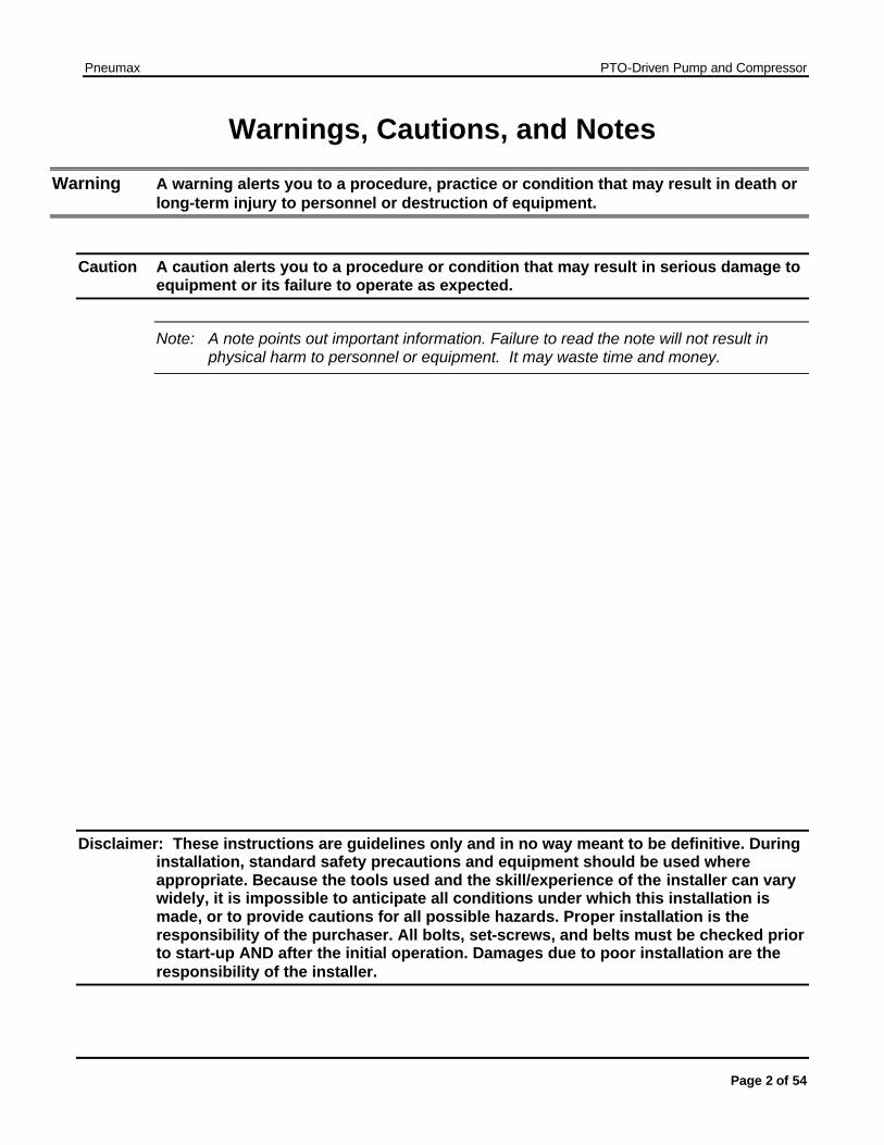
Warnings, Cautions, and Notes
Warning A warning alerts you to a procedure, practice or condition that may result in death or long-term injury to personnel or destruction of equipment.
Caution A caution alerts you to a procedure or condition that may result in serious damage to equipment or its failure to operate as expected.
Note: A note points out important information. Failure to read the note will not result in physical harm to personnel or equipment. It may waste time and money.
Disclaimer: These instructions are guidelines only and in no way meant to be definitive. During installation, standard safety precautions and equipment should be used where appropriate. Because the tools used and the skill/experience of the installer can vary widely, it is impossible to anticipate all conditions under which this installation is made, or to provide cautions for all possible hazards. Proper installation is the responsibility of the purchaser. All bolts, set-screws, and belts must be checked prior to start-up AND after the initial operation. Damages due to poor installation are the responsibility of the installer.
Pneumax PTO-Driven Pump and Compressor
Page 3 of 54
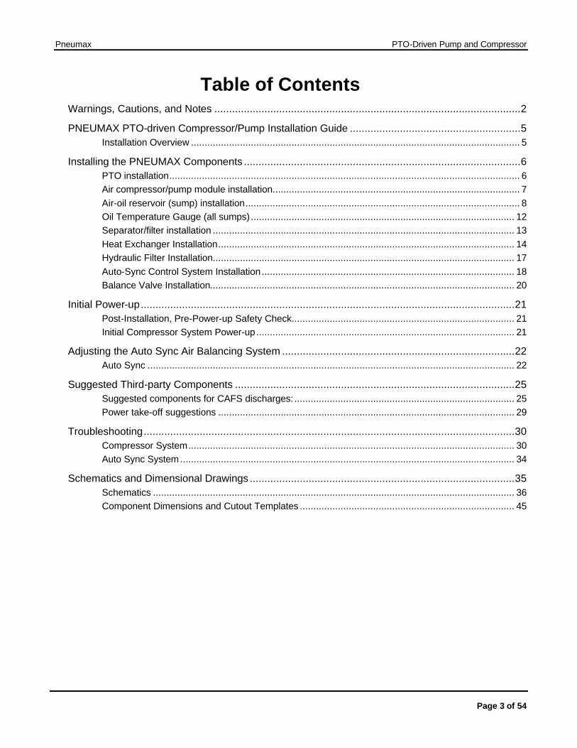
Table of Contents Warnings, Cautions, and Notes ........................................................................................................2
PNEUMAX PTO-driven Compressor/Pump Installation Guide ..........................................................5 Installation Overview ......................................................................................................................... 5
Installing the PNEUMAX Components ..............................................................................................6 PTO installation................................................................................................................................. 6 Air compressor/pump module installation........................................................................................... 7 Air-oil reservoir (sump) installation..................................................................................................... 8 Oil Temperature Gauge (all sumps) ................................................................................................. 12 Separator/filter installation ............................................................................................................... 13 Heat Exchanger Installation............................................................................................................. 14 Hydraulic Filter Installation............................................................................................................... 17 Auto-Sync Control System Installation ............................................................................................. 18 Balance Valve Installation................................................................................................................ 20
Initial Power-up...............................................................................................................................21 Post-Installation, Pre-Power-up Safety Check.................................................................................. 21 Initial Compressor System Power-up............................................................................................... 21
Adjusting the Auto Sync Air Balancing System ...............................................................................22 Auto Sync ....................................................................................................................................... 22
Suggested Third-party Components ...............................................................................................25 Suggested components for CAFS discharges: ................................................................................. 25 Power take-off suggestions ............................................................................................................. 29
Troubleshooting..............................................................................................................................30 Compressor System........................................................................................................................ 30 Auto Sync System........................................................................................................................... 34
Schematics and Dimensional Drawings ..........................................................................................35 Schematics ..................................................................................................................................... 36 Component Dimensions and Cutout Templates ............................................................................... 45
Pneumax PTO-Driven Pump and Compressor
Page 4 of 54
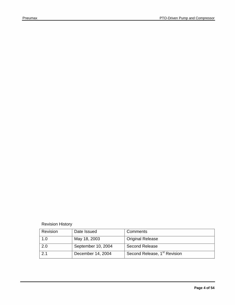
Revision History
Revision Date Issued Comments
1.0 May 18, 2003 Original Release
2.0 September 10, 2004 Second Release
2.1 December 14, 2004 Second Release, 1st Revision
Pneumax PTO-Driven Pump and Compressor
Page 5 of 54
PNEUMAX PTO-driven Compressor/Pump Installation Guide
Installation Overview
Notes: The instructions are for a typical system. The illustrations shown in this manual may differ slightly from the parts that were shipped.
The units all have a PTO-driven pump with a belt-driven compressor mounted above the pump.
The compressor/pump kits do not include:
• (PTO) Transmission power take-off and drive shaft • Foam proportioner, foam tank, foam distribution manifold for CAFS • Air, water and hydraulic hoses and hose fittings • Pump/Compressor module mounting brackets • Air inlet piping • Air and water check valves • Air discharge valves • Air manifold • Master air pressure gauge
New installation tasks include:
• Installing the PTO (follow the manufacturer's instructions) • Installing the foam proportioner (follow the manufacturer's instructions) • Installing the pump/compressor module and connecting it to the PTO • Installing the hydraulic system (sump, filters and cooler) • Installing gauges, valves, and the Auto-Sync controls • Running water, air and hydraulic tubing for control systems, cooling, and
compressed air delivery. • Filling and testing the hydraulic system • Calibrating the Auto-Sync system
Retrofitting into existing apparatus also includes:
• Modifying the water distribution system to install compressed air inputs, foam distribution manifold, check valves, the compressor cooling loop, and the balance valve.
• Installing additional discharges (optional)
Pneumax PTO-Driven Pump and Compressor
Page 6 of 54
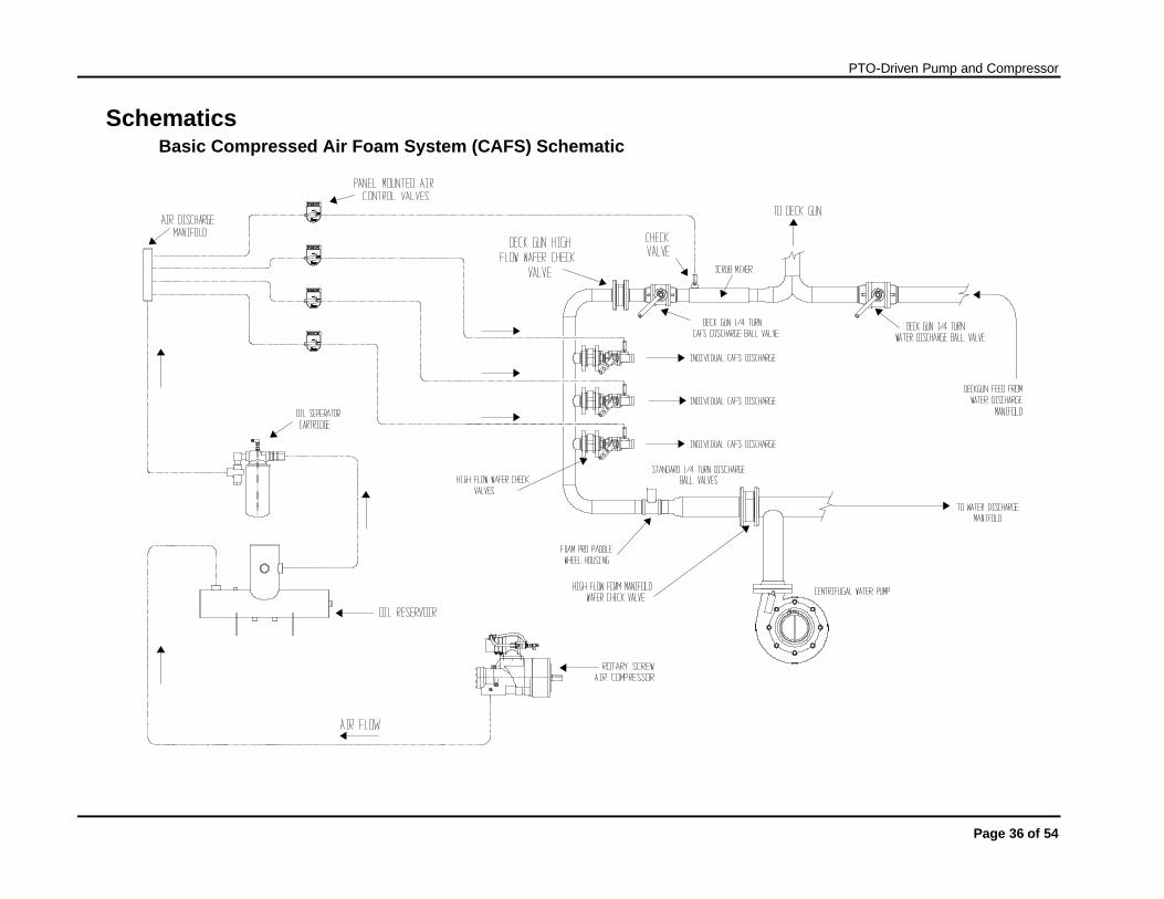
Installing the PNEUMAX Components Refer to the Basic CAFS, Hydraulic, and Auto-Sync schematics in this manual to see how the Pneumax components connect to the vehicle's foam and water distribution systems. Within the guidelines given here, components can be installed wherever there is room for them to be securely mounted. See the dimensional drawings in the rear.
Warning: Do not damage the vehicle chassis during installation. Check with the vehicle manufacturer to make sure the planned welds and bolts are in acceptable areas.
• Components must be bolted to brackets welded to the pump compartment frame, or bolted directly to the pump compartment frame.
• Allow enough clearance for routine maintenance, including clearance for checking oil, adding oil, adjusting pressure, changing filters, cleaning screens or opening drain valves.
• The pump/compressor module must be horizontal, with its drive angle matched to the PTO.
• The sump (oil/air reservoir) can be mounted at the same level as the compressor, or below it. If the sump must be mounted above the compressor (12 inches maximum), contact Pneumax for the correct check valve to prevent compressor flooding.
• The sump must be in the proper orientation. Any extension to the sight glass must be straight and level.
• The oil sight glass must be visible after all the components are installed so oil level can be monitored easily.
• The heat exchanger must be installed horizontally, with the drain at the lowest point. • To prevent damage to hydraulic and air lines, or accidentally disconnecting them, run
them along the support beams of the pump compartment whenever possible, bundled with cable ties or other fasteners.
• Wires, hoses, or tubing that passes through metal, such as a compartment panel, must have a protective bushing or shield around the edge of the hole to protect against abrasion.
• To make troubleshooting easier, use colored air hoses as supplied, and shown on the air schematic.
• Labeling the lines is strongly recommended.
PTO installation Follow the PTO manufacturer's installation guidelines.
Remember that the driveline angles on the pump need to match the driveline angles on the PTO. If you have questions concerning driveline angle, please contact the driveline supplier.
Pneumax PTO-Driven Pump and Compressor
Page 7 of 54
Air compressor/pump module installation
Warning Drive flanges are loosely installed for shipping purposes only. They must be securely fastened during driveline installation process.
All fasteners should be checked by the installer prior to operating the unit.
Caution: The compressor/pump module cannot be installed on its side. It must remain upright, with the air inlet on the top. Incorrect driveline angles between the PTO and the compressor/pump module input shaft can lead to driveline failure and/or cause the air compressor to fail. If you have questions concerning driveline angles, please contact your driveline supplier.
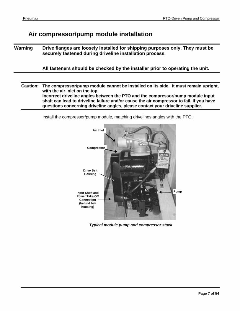
Install the compressor/pump module, matching drivelines angles with the PTO.
Input Shaft and Power Take Off
Connection(behind belt
housing)
Air Inlet
Drive Belt Housing
Pump
Compressor
Typical module pump and compressor stack

Pneumax PTO-Driven Pump and Compressor
Page 8 of 54
Air Inlet and Filter The air inlet on the air compressor can be turned in 90° increments because the bolt pattern is symmetrical. This simplifies installation of the air filter. If you turn the inlet, you will need longer hoses. Either acquire colored hoses locally or contact Pneumax for the correct lengths and colors.
To change the rotation of the air inlet, disconnect the hoses, unbolt the inlet, rotate the inlet, and install new hoses.
Mount the air filter, considering the following factors:
• Air intake area must be unobstructed. • Air intake tubing should be as short and straight as possible. • Maintenance clearance must be adequate for removing and replacing the filter. • The filter should be in an area that is unlikely to get wet.
The air inlet tubing (not included) from the filter to the air inlet is usually made of thin-wall metal tubing and rubber elbows. Plumb it as though it were an engine air inlet. Do not use flexible exhaust tubing or any material that water or dirt can easily penetrate.
Air-oil reservoir (sump) installation
Note: Pneumax will not be responsible for systems where the sump and sight glass are installed such that the oil level cannot be checked or does not display the correct oil level due to improper installation.
The sump works best when it is installed so that the sight glass opening is below the discharge outlet of the air compressor, although mounting the sump at the same level as the compressor is acceptable. In some cases, finding room for the sump can be difficult. It is acceptable to mount the oil sump up to 12 inches higher than the air compressor; however, this requires the installation of a check valve to prevent oil from flooding the compressor. The check valve may be ordered from Pneumax when ordering the system.
Pneumax PTO-Driven Pump and Compressor
Page 9 of 54
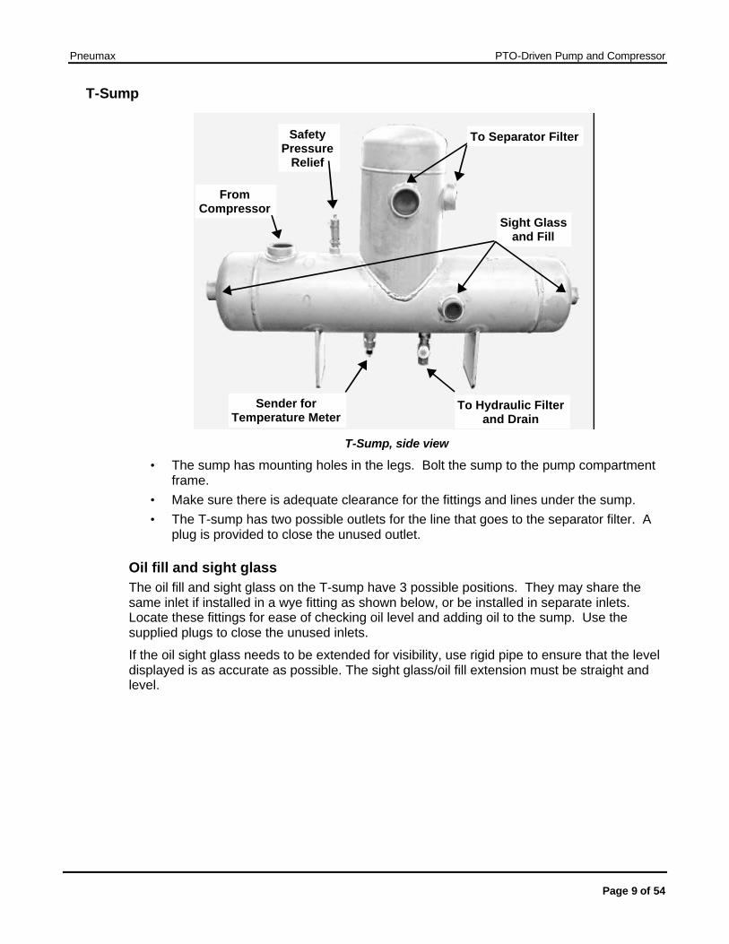
T-Sump
From Compressor
Sight Glass and Fill
To Separator Filter
To Hydraulic Filterand Drain
Safety Pressure
Relief
Sender for Temperature Meter
T-Sump, side view
• The sump has mounting holes in the legs. Bolt the sump to the pump compartment frame.
• Make sure there is adequate clearance for the fittings and lines under the sump. • The T-sump has two possible outlets for the line that goes to the separator filter. A
plug is provided to close the unused outlet.
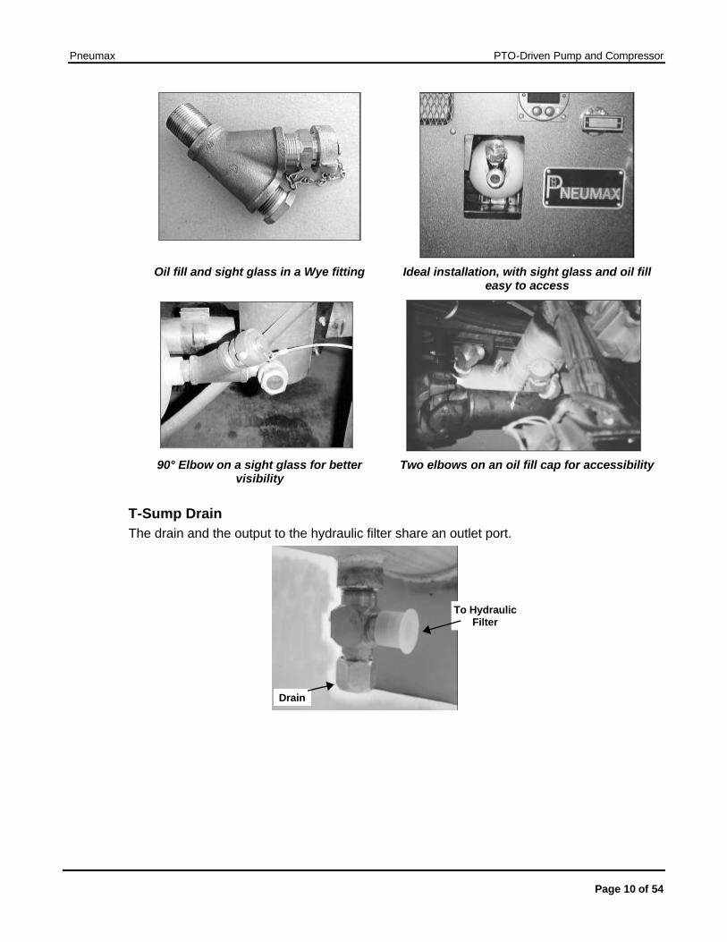
Oil fill and sight glass The oil fill and sight glass on the T-sump have 3 possible positions. They may share the same inlet if installed in a wye fitting as shown below, or be installed in separate inlets. Locate these fittings for ease of checking oil level and adding oil to the sump. Use the supplied plugs to close the unused inlets.
If the oil sight glass needs to be extended for visibility, use rigid pipe to ensure that the level displayed is as accurate as possible. The sight glass/oil fill extension must be straight and level.
Pneumax PTO-Driven Pump and Compressor
Page 10 of 54
Oil fill and sight glass in a Wye fitting Ideal installation, with sight glass and oil fill easy to access
90° Elbow on a sight glass for better
visibility Two elbows on an oil fill cap for accessibility
T-Sump Drain The drain and the output to the hydraulic filter share an outlet port.
To Hydraulic Filter
Drain
Pneumax PTO-Driven Pump and Compressor
Page 11 of 54
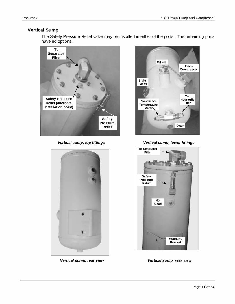
Vertical Sump The Safety Pressure Relief valve may be installed in either of the ports. The remaining ports have no options.
Vertical sump, top fittings Vertical sump, lower fittings
Vertical sump, rear view Vertical sump, rear view
Safety PressureRelief (alternate
installation point)
Safety Pressure
Relief
To Separator
Filter
From Compressor
Oil Fill
Drain
Sight Glass
To Hydraulic
Filter Sender for Temperature
Meter
To Separator Filter
Safety Pressure
Relief
Not Used
Mounting Bracket
Pneumax PTO-Driven Pump and Compressor
Page 12 of 54
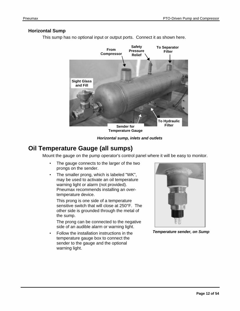
Horizontal Sump This sump has no optional input or output ports. Connect it as shown here.
From Compressor
Sight Glass and Fill
To Separator Filter
To Hydraulic Filter
Safety Pressure
Relief
Sender for Temperature Gauge
Horizontal sump, inlets and outlets
Oil Temperature Gauge (all sumps) Mount the gauge on the pump operator's control panel where it will be easy to monitor.
• The gauge connects to the larger of the two prongs on the sender.
• The smaller prong, which is labeled "WK", may be used to activate an oil temperature warning light or alarm (not provided). Pneumax recommends installing an over-temperature device. This prong is one side of a temperature sensitive switch that will close at 250°F. The other side is grounded through the metal of the sump. The prong can be connected to the negative side of an audible alarm or warning light.
• Follow the installation instructions in the temperature gauge box to connect the sender to the gauge and the optional warning light.
Temperature sender, on Sump
Pneumax PTO-Driven Pump and Compressor
Page 13 of 54
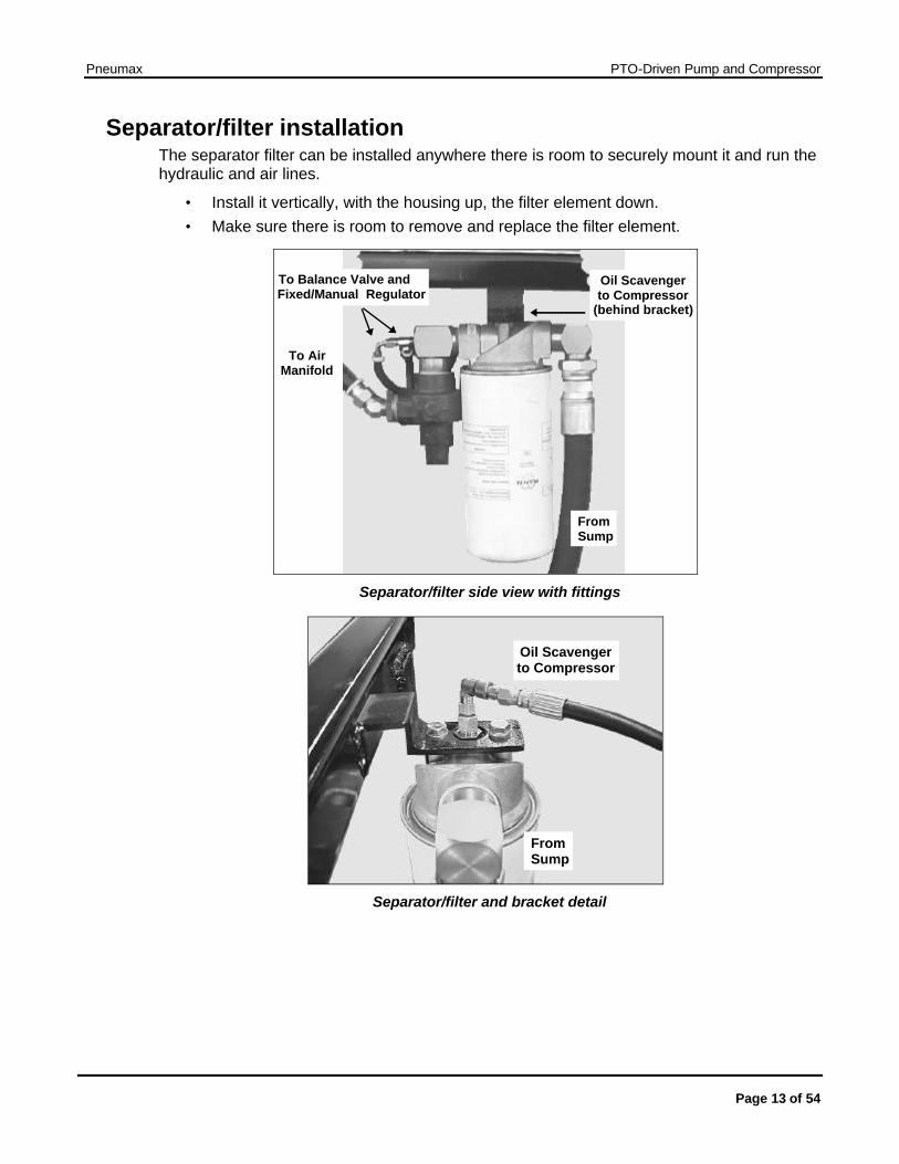
Separator/filter installation The separator filter can be installed anywhere there is room to securely mount it and run the hydraulic and air lines.
• Install it vertically, with the housing up, the filter element down. • Make sure there is room to remove and replace the filter element.
Oil Scavenger to Compressor
(behind bracket)
To Balance Valve and Fixed/Manual Regulator
To Air Manifold
From Sump
Separator/filter side view with fittings
Oil Scavenger to Compressor
From Sump
Separator/filter and bracket detail
Pneumax PTO-Driven Pump and Compressor
Page 14 of 54
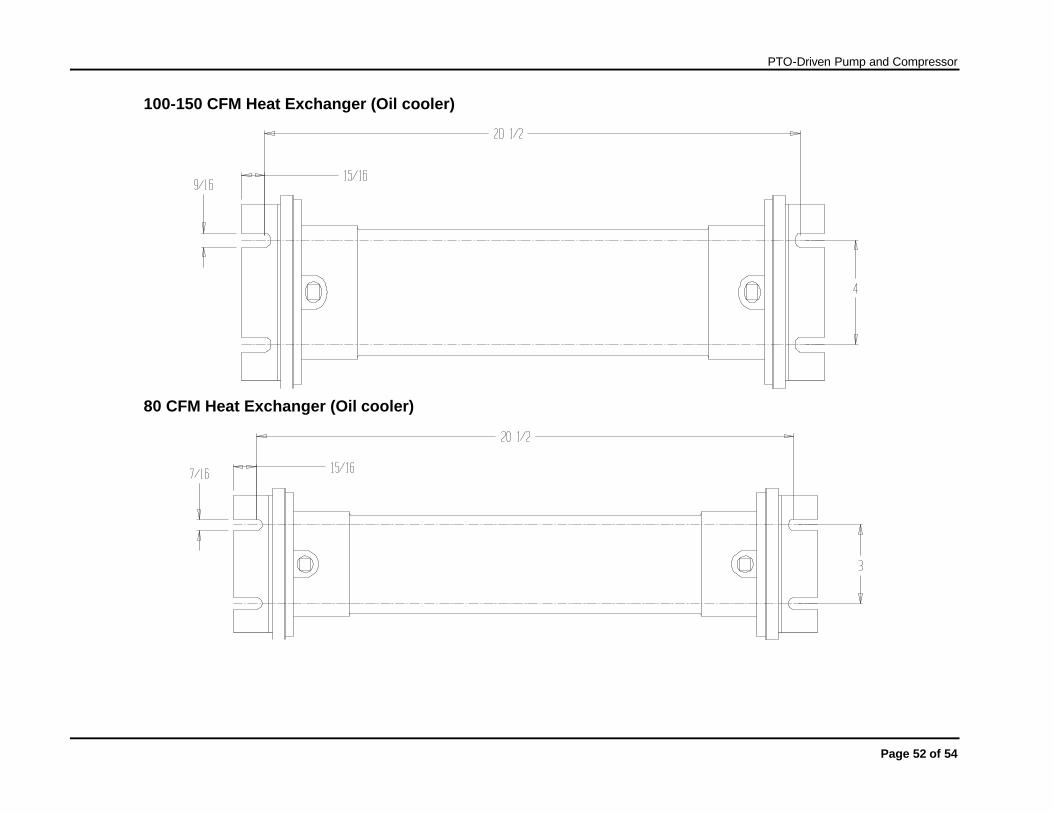
Heat Exchanger Installation
Caution: Do not install a shutoff valve in the heat exchanger water supply. This will result in system overheat and failure, and void the manufacturer’s warranty.
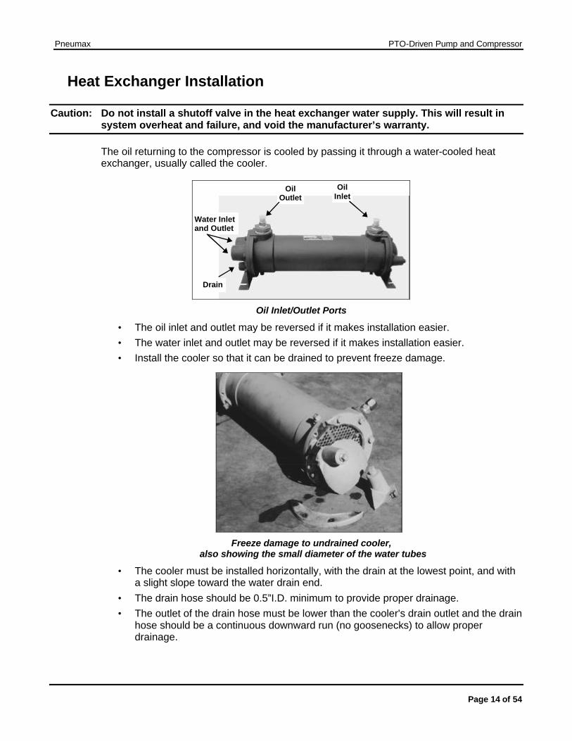
The oil returning to the compressor is cooled by passing it through a water-cooled heat exchanger, usually called the cooler.
Oil Inlet
Oil Outlet
Drain
Water Inlet and Outlet
Oil Inlet/Outlet Ports
• The oil inlet and outlet may be reversed if it makes installation easier. • The water inlet and outlet may be reversed if it makes installation easier. • Install the cooler so that it can be drained to prevent freeze damage.
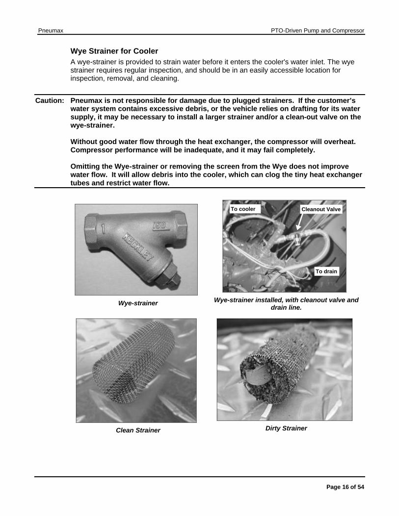
Freeze damage to undrained cooler,
also showing the small diameter of the water tubes
• The cooler must be installed horizontally, with the drain at the lowest point, and with a slight slope toward the water drain end.
• The drain hose should be 0.5”I.D. minimum to provide proper drainage. • The outlet of the drain hose must be lower than the cooler's drain outlet and the drain
hose should be a continuous downward run (no goosenecks) to allow proper drainage.

Pneumax PTO-Driven Pump and Compressor
Page 15 of 54
To mount the cooler on the side of a compartment, unbolt the brackets from the ends and reattach them so the cooler can be installed with the drain at the lowest point.
Bracket
Adjustable Mounting Brackets Cooler mounted on the side of a pump compartment, with the cooler body sloping
toward the drain for better drainage.
Connecting the cooler water lines and wye-strainer The cooler water is supplied by diverting water through a fitting (OEM supplied) from the discharge side of the fire pump (see the Hydraulic Schematic). The cooling water supply hose should be 3/8”I.D. for the 80 CFM model and 1/2” I.D. for the 100-150 CFM models to supply the proper flow for cooling the system. The cooler discharge water may be routed to the booster tank fill tower or returned to the inlet side of the pump, as per the end user's preference.
Normally, coolant water is returned to the booster tank and a check valve is installed in-line to prevent backflow from the tank through the cooler. During drafting and hydrant-supplied operations, the booster tank may overflow because of the cooler water return. If this is objectionable, route the return line to the inlet side of the pump. In this case, it is not necessary to install an in-line check valve, but it will be necessary for the pump operator to open the tank fill valve during operation to prevent overheating the fire pump.
Pneumax PTO-Driven Pump and Compressor
Page 16 of 54
Wye Strainer for Cooler A wye-strainer is provided to strain water before it enters the cooler's water inlet. The wye strainer requires regular inspection, and should be in an easily accessible location for inspection, removal, and cleaning.
Caution: Pneumax is not responsible for damage due to plugged strainers. If the customer’s water system contains excessive debris, or the vehicle relies on drafting for its water supply, it may be necessary to install a larger strainer and/or a clean-out valve on the wye-strainer. Without good water flow through the heat exchanger, the compressor will overheat. Compressor performance will be inadequate, and it may fail completely. Omitting the Wye-strainer or removing the screen from the Wye does not improve water flow. It will allow debris into the cooler, which can clog the tiny heat exchanger tubes and restrict water flow.
Wye-strainer
To drain
To cooler Cleanout Valve
Wye-strainer installed, with cleanout valve and
drain line.
Clean Strainer
Dirty Strainer
Pneumax PTO-Driven Pump and Compressor
Page 17 of 54
Hydraulic Filter Installation
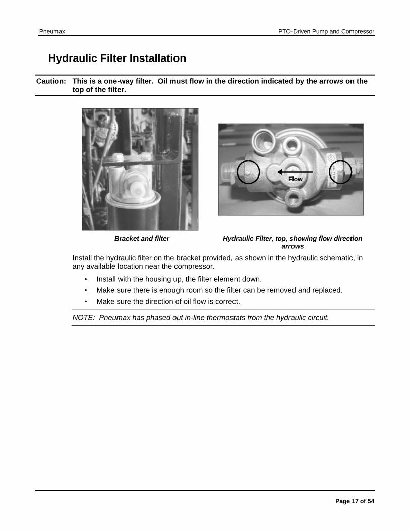
Caution: This is a one-way filter. Oil must flow in the direction indicated by the arrows on the top of the filter.
Flow
Bracket and filter Hydraulic Filter, top, showing flow direction arrows
Install the hydraulic filter on the bracket provided, as shown in the hydraulic schematic, in any available location near the compressor.
• Install with the housing up, the filter element down. • Make sure there is enough room so the filter can be removed and replaced. • Make sure the direction of oil flow is correct.
NOTE: Pneumax has phased out in-line thermostats from the hydraulic circuit.
Pneumax PTO-Driven Pump and Compressor
Page 18 of 54
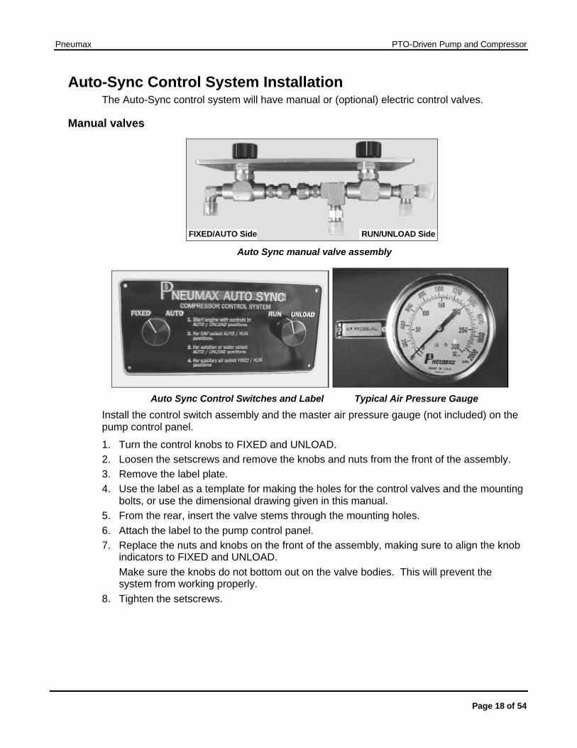
Auto-Sync Control System Installation The Auto-Sync control system will have manual or (optional) electric control valves.
Manual valves
FIXED/AUTO Side RUN/UNLOAD Side Auto Sync manual valve assembly
Auto Sync Control Switches and Label Typical Air Pressure Gauge
Install the control switch assembly and the master air pressure gauge (not included) on the pump control panel.
1. Turn the control knobs to FIXED and UNLOAD. 2. Loosen the setscrews and remove the knobs and nuts from the front of the assembly. 3. Remove the label plate. 4. Use the label as a template for making the holes for the control valves and the mounting
bolts, or use the dimensional drawing given in this manual. 5. From the rear, insert the valve stems through the mounting holes. 6. Attach the label to the pump control panel. 7. Replace the nuts and knobs on the front of the assembly, making sure to align the knob
indicators to FIXED and UNLOAD. Make sure the knobs do not bottom out on the valve bodies. This will prevent the system from working properly.
8. Tighten the setscrews.
Pneumax PTO-Driven Pump and Compressor
Page 19 of 54
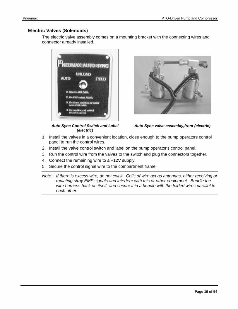
Electric Valves (Solenoids) The electric valve assembly comes on a mounting bracket with the connecting wires and connector already installed.
Auto Sync Control Switch and Label (electric)
Auto Sync valve assembly,front (electric)
1. Install the valves in a convenient location, close enough to the pump operators control panel to run the control wires.
2. Install the valve control switch and label on the pump operator's control panel. 3. Run the control wire from the valves to the switch and plug the connectors together. 4. Connect the remaining wire to a +12V supply. 5. Secure the control signal wire to the compartment frame.
Note: If there is excess wire, do not coil it. Coils of wire act as antennas, either receiving or radiating stray EMF signals and interfere with this or other equipment. Bundle the wire harness back on itself, and secure it in a bundle with the folded wires parallel to each other.
Pneumax PTO-Driven Pump and Compressor
Page 20 of 54
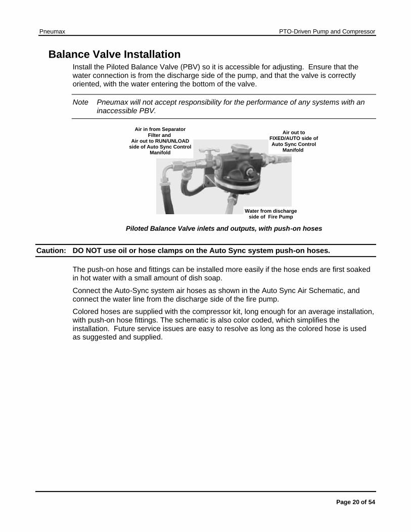
Balance Valve Installation Install the Piloted Balance Valve (PBV) so it is accessible for adjusting. Ensure that the water connection is from the discharge side of the pump, and that the valve is correctly oriented, with the water entering the bottom of the valve.
Note Pneumax will not accept responsibility for the performance of any systems with an inaccessible PBV.
Air in from Separator Filter and
Air out to RUN/UNLOAD side of Auto Sync Control
Manifold
Air out to FIXED/AUTO side of Auto Sync Control
Manifold
Water from discharge side of Fire Pump
Piloted Balance Valve inlets and outputs, with push-on hoses
Caution: DO NOT use oil or hose clamps on the Auto Sync system push-on hoses.
The push-on hose and fittings can be installed more easily if the hose ends are first soaked in hot water with a small amount of dish soap.
Connect the Auto-Sync system air hoses as shown in the Auto Sync Air Schematic, and connect the water line from the discharge side of the fire pump.
Colored hoses are supplied with the compressor kit, long enough for an average installation, with push-on hose fittings. The schematic is also color coded, which simplifies the installation. Future service issues are easy to resolve as long as the colored hose is used as suggested and supplied.
Pneumax PTO-Driven Pump and Compressor
Page 21 of 54
Initial Power-up Post-Installation, Pre-Power-up Safety Check
Before you power-up the Pneumax system:
1. Remove all tools, shop towels, hose trimmings and other debris from the compartments. 2. Double-check all hydraulic, air and water lines against the schematics, testing to make
sure each connection is tight and that the hose is fully inserted into the fitting. 3. Check all of the unused inlets: plastic shipping caps must be removed and replaced with
the appropriate plug or cap. 4. Make sure all drain valves are closed. 5. Make sure the gauges are connected to the appropriate sender (temperature, pressure,
etc.) 6. Fill the sump with the specified hydraulic oil until the oil level is 1/2 way up the sight
glass. You will need to add more oil later, to compensate for oil that remains in the hydraulic lines and the compressor. Oil used in the system is ISO 68wt hydraulic oil. It must be "Low-foaming" or "Anti-foam".
7. Make sure the foam proportioner is operating properly. (see the manufacturer's installation guide).
8. Make sure the fire pump is operating properly and that water flows through the oil cooler. 9. Make sure the connection between the compressor drive shaft and the PTO is secure
and that the driveline angles match.
Initial Compressor System Power-up
Warning: Compressed air can be dangerous. Make sure the pressure is allowed to bleed down to atmospheric pressure before opening any connections or valves.
1. Remove the air filter plumbing and pour 8 to 16 ounces of hydraulic oil into the air inlet of the compressor.
2. Replace the air filter plumbing. 3. Place the Auto Sync system in UNLOAD and AUTO (UNLOAD for electric Auto Sync) 4. Start the vehicle's engine and engage the PTO. 5. With the system powered up, turn the Auto Sync to the RUN/FIXED positions (FIXED for
electric Auto Sync). Air pressure should rise to about 110 PSI. 6. Check for leaks by listening for hissing noises at the fittings. 7. Shut the PTO off, allow the pressure to bleed off, then add oil to the sump to bring the oil
level 1/2 way up the sight glass. 8. Proceed to "Adjusting the Auto Sync Air Balancing System".
Pneumax PTO-Driven Pump and Compressor
Page 22 of 54
Adjusting the Auto Sync Air Balancing System CAFS retrofit kits and any other system shipped as separate components will need calibrating after installation.
Note: Before you make any adjustments, make sure the oil level in the sump is correct, the air and oil filters are not overdue for servicing, and the air lines do not have leaks or obstructions. Do not adjust the Auto Sync components to compensate for problems elsewhere in the CAF system.
Always start by adjusting UNLOAD mode, then FIXED, then AUTO.
Auto Sync 1. UNLOAD Mode Adjustment
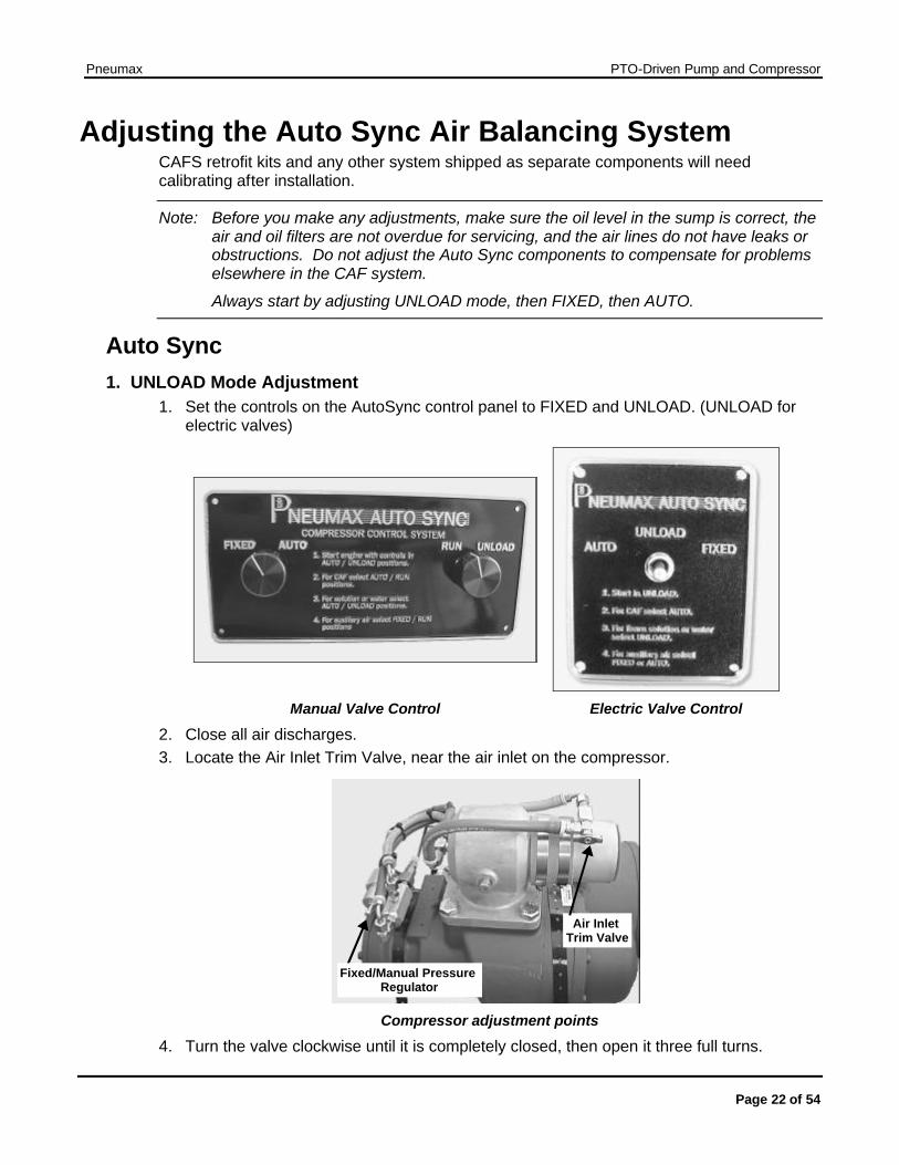
1. Set the controls on the AutoSync control panel to FIXED and UNLOAD. (UNLOAD for electric valves)
Manual Valve Control Electric Valve Control
2. Close all air discharges. 3. Locate the Air Inlet Trim Valve, near the air inlet on the compressor.
Air Inlet Trim Valve
Fixed/Manual Pressure Regulator
Compressor adjustment points
4. Turn the valve clockwise until it is completely closed, then open it three full turns.
Pneumax PTO-Driven Pump and Compressor
Page 23 of 54
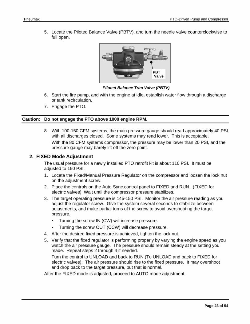
5. Locate the Piloted Balance Valve (PBTV), and turn the needle valve counterclockwise to full open.
PBT Valve
Piloted Balance Trim Valve (PBTV)
6. Start the fire pump, and with the engine at idle, establish water flow through a discharge or tank recirculation.
7. Engage the PTO.
Caution: Do not engage the PTO above 1000 engine RPM.
8. With 100-150 CFM systems, the main pressure gauge should read approximately 40 PSI with all discharges closed. Some systems may read lower. This is acceptable. With the 80 CFM systems compressor, the pressure may be lower than 20 PSI, and the pressure gauge may barely lift off the zero point.
2. FIXED Mode Adjustment The usual pressure for a newly installed PTO retrofit kit is about 110 PSI. It must be adjusted to 150 PSI. 1. Locate the Fixed/Manual Pressure Regulator on the compressor and loosen the lock nut
on the adjustment screw. 2. Place the controls on the Auto Sync control panel to FIXED and RUN. (FIXED for
electric valves) Wait until the compressor pressure stabilizes. 3. The target operating pressure is 145-150 PSI. Monitor the air pressure reading as you
adjust the regulator screw. Give the system several seconds to stabilize between adjustments, and make partial turns of the screw to avoid overshooting the target pressure. • Turning the screw IN (CW) will increase pressure. • Turning the screw OUT (CCW) will decrease pressure.
4. After the desired fixed pressure is achieved, tighten the lock nut. 5. Verify that the fixed regulator is performing properly by varying the engine speed as you
watch the air pressure gauge. The pressure should remain steady at the setting you made. Repeat steps 2 through 4 if needed. Turn the control to UNLOAD and back to RUN (To UNLOAD and back to FIXED for electric valves). The air pressure should rise to the fixed pressure. It may overshoot and drop back to the target pressure, but that is normal.
After the FIXED mode is adjusted, proceed to AUTO mode adjustment.
Pneumax PTO-Driven Pump and Compressor
Page 24 of 54
3. AUTO Mode Adjustment The pressure for the FIXED mode must have been correctly set before you attempt to adjust the AUTO mode.
1. Make sure the fire pump is operating at 100 PSI at the main discharge, with minimal flow.
2. Place the controls on the Auto Sync control panel to AUTO and RUN. (AUTO for electric valves.)
3. Read the main air pressure and water discharge pressure gauges. 4. The air pressure reading should be equal or up to 5% higher than the water pressure. If
the readings are in this range, go to step 7 and verify the operation at other pressures. 5. If the air pressure is not within +5% of the water pressure, adjust it as follows:
• If the air pressure is too high, turn the Air Inlet Trim Valve clockwise in 1/2 turn increments to close it, checking air and water pressure after each 1/2 turn.
• If the air pressure is too low, turn the Air Inlet Trim Valve counterclockwise 1/2 turn to open it and check pressures. If the air pressure is still too low, open the valve another 1/2 turn and check the pressures again. Do not open the Air Inlet Trim Valve more than this. Use the PBTV if the pressure remains too low.
6. If the air pressure remains too low, close the needle valve on the Piloted Balance Trim Valve (PBTV) one full turn clockwise and check the pressure gauges. Repeat closing the PBTV one full turn until the air pressure is equal to or up to 5% higher than the water pressure. If the air pressure is too high after a full-turn of the PBTV, turn the Air Inlet Trim Valve clockwise to lower the pressure until the air pressure is equal to or up to 5% higher than the water pressure.
7. Verify the Auto-Sync system settings by varying the fire pump discharge pressure and monitoring the water and air pressure gauges. The air pressure should rise and fall with the water pressure, matching it within 5%. Pressures should match at static pressure only. It is normal for the pressures to be unmatched when flowing water, air, or solution.
Pneumax PTO-Driven Pump and Compressor
Page 25 of 54
Suggested Third-party Components Note: These are guidelines useful for many installations, but selection of
third-party components is at the discretion of the system installer or vehicle manufacturer.
Suggested components for CAFS discharges: The installer must provide fittings and tubing to connect the CAFS components to the vehicle's discharge outlets. These are suggested parts for the common discharge sizes. If the planned discharge system is not covered in this guideline, please contact Pneumax.
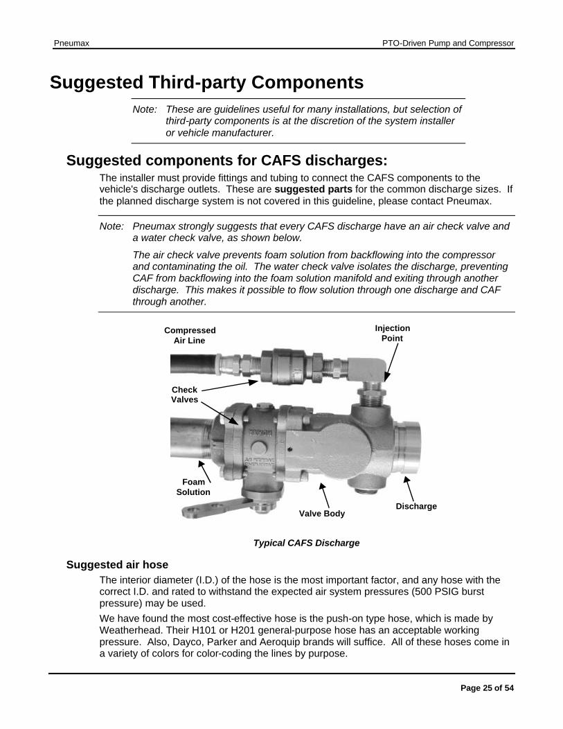
Note: Pneumax strongly suggests that every CAFS discharge have an air check valve and a water check valve, as shown below.
The air check valve prevents foam solution from backflowing into the compressor and contaminating the oil. The water check valve isolates the discharge, preventing CAF from backflowing into the foam solution manifold and exiting through another discharge. This makes it possible to flow solution through one discharge and CAF through another.
Check Valves
DischargeValve Body
Injection Point
Compressed Air Line
Foam Solution
Check Valves
Typical CAFS Discharge
Suggested air hose The interior diameter (I.D.) of the hose is the most important factor, and any hose with the correct I.D. and rated to withstand the expected air system pressures (500 PSIG burst pressure) may be used. We have found the most cost-effective hose is the push-on type hose, which is made by Weatherhead. Their H101 or H201 general-purpose hose has an acceptable working pressure. Also, Dayco, Parker and Aeroquip brands will suffice. All of these hoses come in a variety of colors for color-coding the lines by purpose.
Pneumax PTO-Driven Pump and Compressor
Page 26 of 54
The other type of hose that is commonly used for air discharges is hydraulic hose. Usually this is an SAE 100R1 type. Typically, hydraulic hose is not necessary on the air discharge circuit, because the system air pressure will not exceed 150 psi. Also, the hose and fittings for hydraulic hose are bulky and expensive.
Air brake hose may also be used, provided the inside diameters are correct:
.375” OD is .250” ID
.500” OD is .375” ID
.625” OD is .500” ID
.750” OD is .625” ID
Discharge fittings
Suggested for 1” booster reel or 1” remote discharge: Use ? ” air hose
1- Water Check Valve (same size as discharge valve, suggest ball & cone style) 1-12BV Class 1 Valve
You may also need to install an air pinch valve behind the panel for tuning this discharge.
Fittings per discharge: 4 - #6 JIC x 6 push-lock 2 - #6 JIC x1/2” NPTM-90 1 – ¾” NPT-M x1/2”npt-f bushing 1 - #6 JIC x ½”NPT-M 1 - ¾” NPT nipple 1- ½” Air Check Valve
If an electric solenoid valve is used for air instead of manual valve, use:
½” direct acting solenoid valve Toggle switch SPST (suggest switch guard) ½”x 3/8” NPT bushing #6x3/8” Female 37 JIC swivel to NPT-M adapter
Delete the following items:
#6JIC x 6 push-lock 1- #6 JIC x ½” NPT-M 90
Pneumax PTO-Driven Pump and Compressor
Page 27 of 54
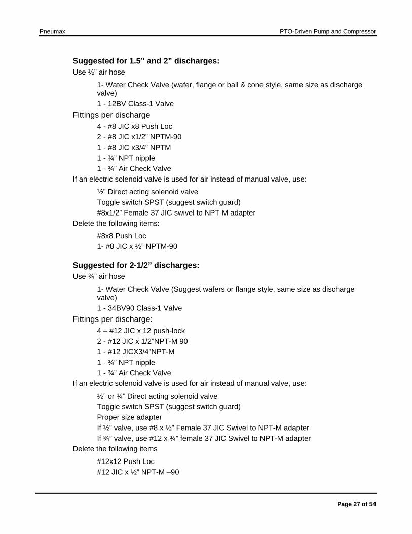
Suggested for 1.5” and 2” discharges: Use ½” air hose
1- Water Check Valve (wafer, flange or ball & cone style, same size as discharge valve) 1 - 12BV Class-1 Valve
Fittings per discharge 4 - #8 JIC x8 Push Loc 2 - #8 JIC x1/2” NPTM-90 1 - #8 JIC x3/4” NPTM 1 - ¾” NPT nipple 1 - ¾” Air Check Valve
If an electric solenoid valve is used for air instead of manual valve, use:
½” Direct acting solenoid valve Toggle switch SPST (suggest switch guard) #8x1/2” Female 37 JIC swivel to NPT-M adapter
Delete the following items:
#8x8 Push Loc 1- #8 JIC x ½” NPTM-90
Suggested for 2-1/2” discharges: Use ¾” air hose
1- Water Check Valve (Suggest wafers or flange style, same size as discharge valve) 1 - 34BV90 Class-1 Valve
Fittings per discharge: 4 – #12 JIC x 12 push-lock 2 - #12 JIC x 1/2”NPT-M 90 1 - #12 JICX3/4”NPT-M 1 - ¾” NPT nipple 1 - ¾” Air Check Valve
If an electric solenoid valve is used for air instead of manual valve, use:
½” or ¾” Direct acting solenoid valve Toggle switch SPST (suggest switch guard) Proper size adapter If ½” valve, use #8 x ½” Female 37 JIC Swivel to NPT-M adapter If ¾” valve, use #12 x ¾” female 37 JIC Swivel to NPT-M adapter
Delete the following items
#12x12 Push Loc #12 JIC x ½” NPT-M –90
Pneumax PTO-Driven Pump and Compressor
Page 28 of 54
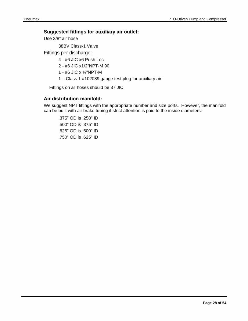
Suggested fittings for auxiliary air outlet: Use 3/8” air hose
38BV Class-1 Valve Fittings per discharge:
4 - #6 JIC x6 Push Loc 2 - #6 JIC x1/2”NPT-M 90 1 - #6 JIC x ¼”NPT-M 1 – Class 1 #102089 gauge test plug for auxiliary air
Fittings on all hoses should be 37 JIC
Air distribution manifold: We suggest NPT fittings with the appropriate number and size ports. However, the manifold can be built with air brake tubing if strict attention is paid to the inside diameters:
.375” OD is .250” ID
.500” OD is .375” ID
.625” OD is .500” ID
.750” OD is .625” ID
Pneumax PTO-Driven Pump and Compressor
Page 29 of 54
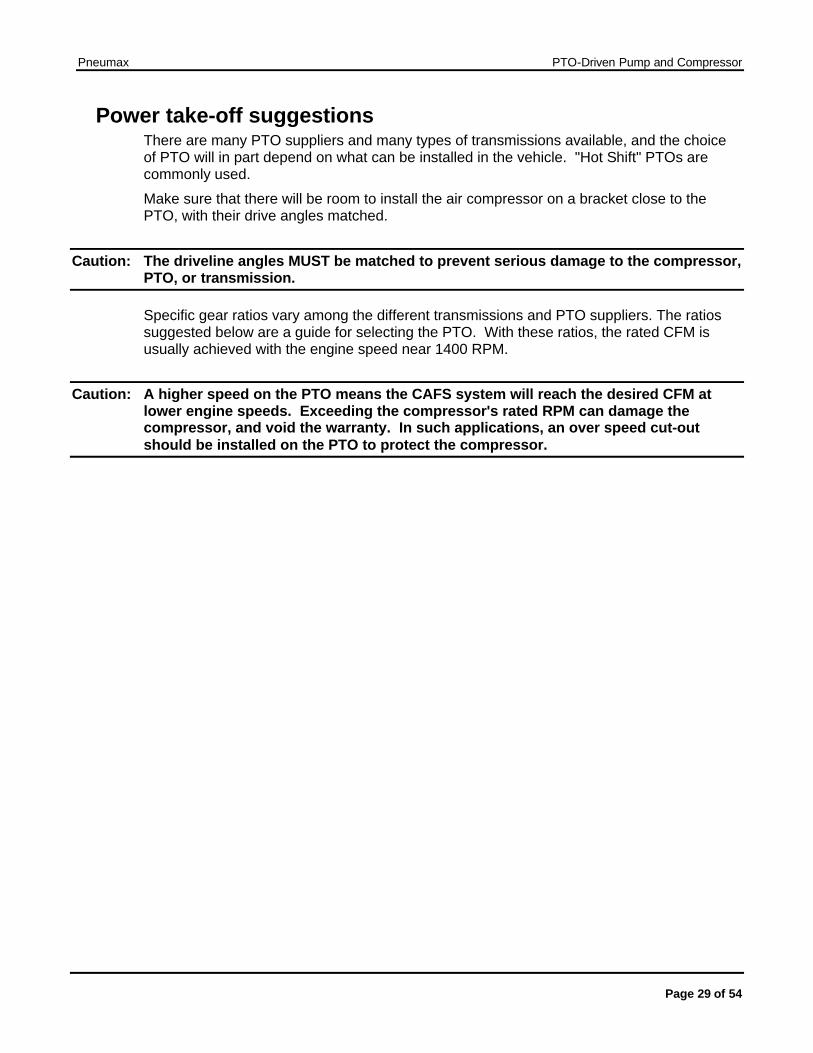
Power take-off suggestions There are many PTO suppliers and many types of transmissions available, and the choice of PTO will in part depend on what can be installed in the vehicle. "Hot Shift" PTOs are commonly used.
Make sure that there will be room to install the air compressor on a bracket close to the PTO, with their drive angles matched.
Caution: The driveline angles MUST be matched to prevent serious damage to the compressor, PTO, or transmission.
Specific gear ratios vary among the different transmissions and PTO suppliers. The ratios suggested below are a guide for selecting the PTO. With these ratios, the rated CFM is usually achieved with the engine speed near 1400 RPM.
Caution: A higher speed on the PTO means the CAFS system will reach the desired CFM at lower engine speeds. Exceeding the compressor's rated RPM can damage the compressor, and void the warranty. In such applications, an over speed cut-out should be installed on the PTO to protect the compressor.

Pneumax PTO-Driven Pump and Compressor
Page 30 of 54
Troubleshooting Compressor System
Observed Symptom Probable cause Suggested fix
Lack of air pressure from compressor
Lack of air supply to clutch (for air-clutch systems)
Repair air leak or re-establish air supply
Compressor not engaging No PTO engagement Confirm OK TO PUMP light is on, if not check
wiring for damage or disconnected wire, check PTO.
Confirm 40 PSI in UNLOAD position (200 CFM systems) and 50+ in run position. Smaller compressors have lower UNLOAD pressures.
Auto Sync switches not in correct position.
Verify when in FIXED/RUN whether pressure reflects 145-150 PSI
Air discharge solenoid not working Repair/replace solenoid
(electric valves) Verify there is power to the air solenoid and check operation of solenoid.
Air solenoid working - leak between solenoid and discharge. Repair leak.
Air check valve defective Replace or correct installation.
Trim valve out of adjustment Refer to trim valve instructions
Restricted minimum pressure valve
Clean rust or debris from valve
Air plumbed before discharge valve seal
Relocate to discharge side of discharge valve
Compressor engaging.
No air supply to discharges, or insufficient air supply.
Incorrect air line size Size according to discharge and replace line with correct size.
System functioning correctly, pressure gauge reading obviously incorrect.
Gauge malfunction, air line detached
Check for air leaks, replace gauge
FIXED has pressure but AUTO has no pressure
No water supply to balance valve.
Check line for proper installation, with no kinks or obstructions.
Refer to trim valve instructions.
Air discharge pressure too high Red hose circuit (compressed air control) has leak or is disconnected.
Repair leak or attach hose
Pneumax PTO-Driven Pump and Compressor
Page 31 of 54
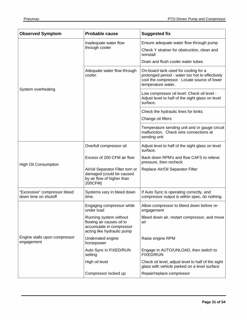
Observed Symptom Probable cause Suggested fix
Inadequate water flow through cooler
Ensure adequate water flow through pump
Check Y strainer for obstruction, clean and reinstall
Drain and flush cooler water tubes
On-board tank used for cooling for a prolonged period - water too hot to effectively cool the compressor. Locate source of lower temperature water.
Low compressor oil level: Check oil level - Adjust level to half of the sight glass on level surface.
Check the hydraulic lines for kinks
Change oil filters
System overheating
Adequate water flow through cooler.
Temperature sending unit and or gauge circuit malfunction. Check wire connections at sending unit
High Oil Consumption
Overfull compressor oil
Excess of 200 CFM air flow
Air/oil Separator Filter torn or damaged (could be caused by air flow of higher than 200CFM)
Adjust level to half of the sight glass on level surface.
Back down RPM's and flow CAFS to relieve pressure, then recheck
Replace Air/Oil Separator Filter
"Excessive" compressor bleed down time on shutoff
Systems vary in bleed down time.
If Auto Sync is operating correctly, and compressor output is within spec, do nothing.
Engine stalls upon compressor engagement
Engaging compressor while under load
Running system without flowing air causes oil to accumulate in compressor acting like hydraulic pump
Underrated engine horsepower
Auto Sync in FIXED/RUN setting
High oil level
Compressor locked up
Allow compressor to bleed down before re-engagement
Bleed down air, restart compressor, and move air
Raise engine RPM
Engage in AUTO/UNLOAD, then switch to FIXED/RUN
Check oil level, adjust level to half of the sight glass with vehicle parked on a level surface
Repair/replace compressor
Pneumax PTO-Driven Pump and Compressor
Page 32 of 54
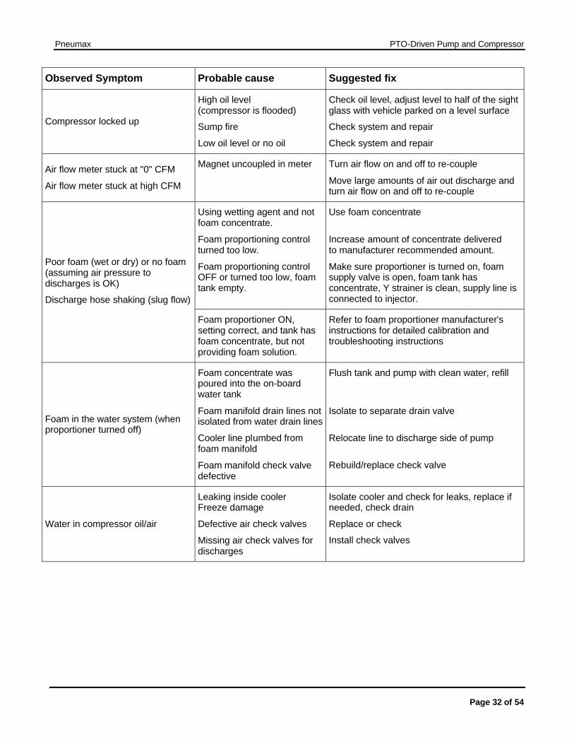
Observed Symptom Probable cause Suggested fix
Compressor locked up
High oil level (compressor is flooded)
Sump fire
Low oil level or no oil
Check oil level, adjust level to half of the sight glass with vehicle parked on a level surface
Check system and repair
Check system and repair
Air flow meter stuck at "0" CFM
Air flow meter stuck at high CFM
Magnet uncoupled in meter Turn air flow on and off to re-couple
Move large amounts of air out discharge and turn air flow on and off to re-couple
Using wetting agent and not foam concentrate.
Foam proportioning control turned too low.
Foam proportioning control OFF or turned too low, foam tank empty.
Use foam concentrate
Increase amount of concentrate delivered to manufacturer recommended amount.
Make sure proportioner is turned on, foam supply valve is open, foam tank has concentrate, Y strainer is clean, supply line is connected to injector.
Poor foam (wet or dry) or no foam (assuming air pressure to discharges is OK)
Discharge hose shaking (slug flow)
Foam proportioner ON, setting correct, and tank has foam concentrate, but not providing foam solution.
Refer to foam proportioner manufacturer's instructions for detailed calibration and troubleshooting instructions
Foam in the water system (when proportioner turned off)
Foam concentrate was poured into the on-board water tank
Foam manifold drain lines not isolated from water drain lines
Cooler line plumbed from foam manifold
Foam manifold check valve defective
Flush tank and pump with clean water, refill
Isolate to separate drain valve
Relocate line to discharge side of pump
Rebuild/replace check valve
Water in compressor oil/air
Leaking inside cooler Freeze damage
Defective air check valves
Missing air check valves for discharges
Isolate cooler and check for leaks, replace if needed, check drain
Replace or check
Install check valves
Pneumax PTO-Driven Pump and Compressor
Page 33 of 54
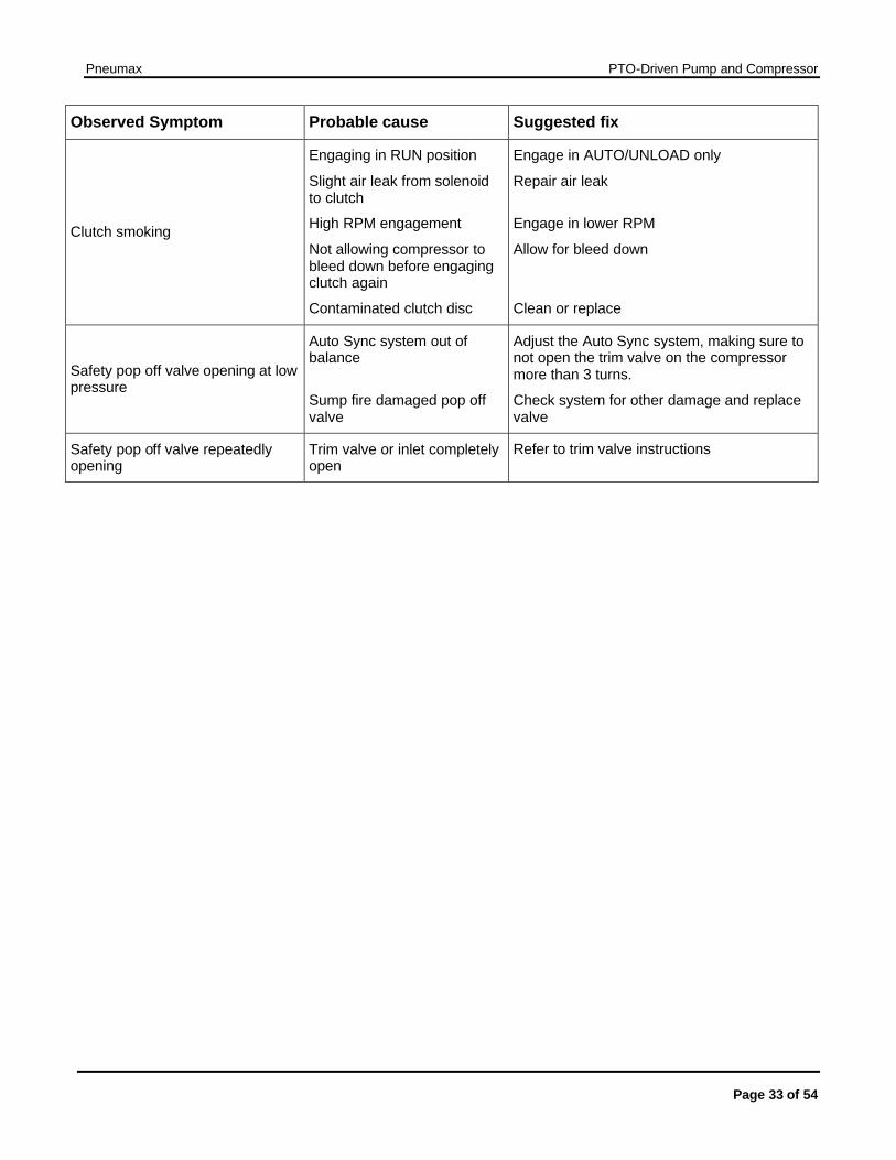
Observed Symptom Probable cause Suggested fix
Clutch smoking
Engaging in RUN position
Slight air leak from solenoid to clutch
High RPM engagement
Not allowing compressor to bleed down before engaging clutch again
Contaminated clutch disc
Engage in AUTO/UNLOAD only
Repair air leak
Engage in lower RPM
Allow for bleed down
Clean or replace
Safety pop off valve opening at low pressure
Auto Sync system out of balance
Sump fire damaged pop off valve
Adjust the Auto Sync system, making sure to not open the trim valve on the compressor more than 3 turns.
Check system for other damage and replace valve
Safety pop off valve repeatedly opening
Trim valve or inlet completely open
Refer to trim valve instructions
Pneumax PTO-Driven Pump and Compressor
Page 34 of 54
Auto Sync System This seldom needs adjusting after the initial setup if the rest of the system is well maintained.
Note: Do not adjust the Auto Sync components to compensate for problems elsewhere in the CAFS system.
Before you make any adjustments, make sure the oil level in the sump is correct, the air and oil filters are not overdue for servicing, the oil is not overdue for changing, the compressor is not overheating, the oil cooler strainer is clean, and the air lines do not have leaks.
Always start by adjusting UNLOAD mode, then FIXED, then AUTO.
A common problem is unauthorized adjustment of the balance valve in an attempt to improve performance. If unauthorized adjustments to the Auto Sync are a problem we suggest placing a seal over the adjustment points. This will let maintenance personnel know if the system has been tampered with.
PTO-Driven Pump and Compressor
Page 35 of 54
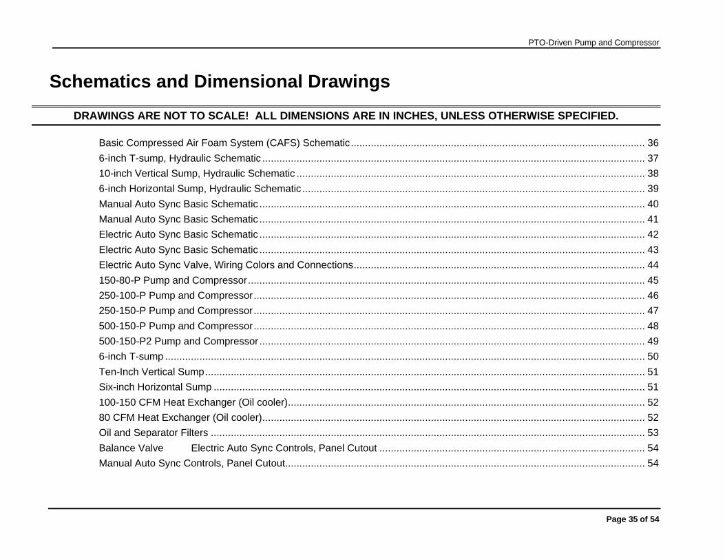
Schematics and Dimensional Drawings
DRAWINGS ARE NOT TO SCALE! ALL DIMENSIONS ARE IN INCHES, UNLESS OTHERWISE SPECIFIED.
Basic Compressed Air Foam System (CAFS) Schematic....................................................................................................... 36 6-inch T-sump, Hydraulic Schematic ...................................................................................................................................... 37 10-inch Vertical Sump, Hydraulic Schematic .......................................................................................................................... 38 6-inch Horizontal Sump, Hydraulic Schematic ........................................................................................................................ 39 Manual Auto Sync Basic Schematic ....................................................................................................................................... 40 Manual Auto Sync Basic Schematic ....................................................................................................................................... 41 Electric Auto Sync Basic Schematic ....................................................................................................................................... 42 Electric Auto Sync Basic Schematic ....................................................................................................................................... 43 Electric Auto Sync Valve, Wiring Colors and Connections...................................................................................................... 44 150-80-P Pump and Compressor........................................................................................................................................... 45 250-100-P Pump and Compressor......................................................................................................................................... 46 250-150-P Pump and Compressor......................................................................................................................................... 47 500-150-P Pump and Compressor......................................................................................................................................... 48 500-150-P2 Pump and Compressor ....................................................................................................................................... 49 6-inch T-sump ........................................................................................................................................................................ 50 Ten-Inch Vertical Sump.......................................................................................................................................................... 51 Six-inch Horizontal Sump ....................................................................................................................................................... 51 100-150 CFM Heat Exchanger (Oil cooler)............................................................................................................................. 52 80 CFM Heat Exchanger (Oil cooler)...................................................................................................................................... 52 Oil and Separator Filters ........................................................................................................................................................ 53 Balance Valve Electric Auto Sync Controls, Panel Cutout ............................................................................................. 54 Manual Auto Sync Controls, Panel Cutout.............................................................................................................................. 54
PTO-Driven Pump and Compressor
Page 36 of 54
Schematics Basic Compressed Air Foam System (CAFS) Schematic
PTO-Driven Pump and Compressor
Page 37 of 54
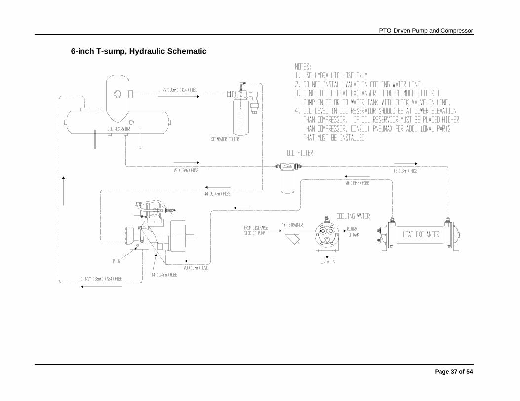
6-inch T-sump, Hydraulic Schematic

PTO-Driven Pump and Compressor
Page 38 of 54
10-inch Vertical Sump, Hydraulic Schematic
PTO-Driven Pump and Compressor
Page 39 of 54
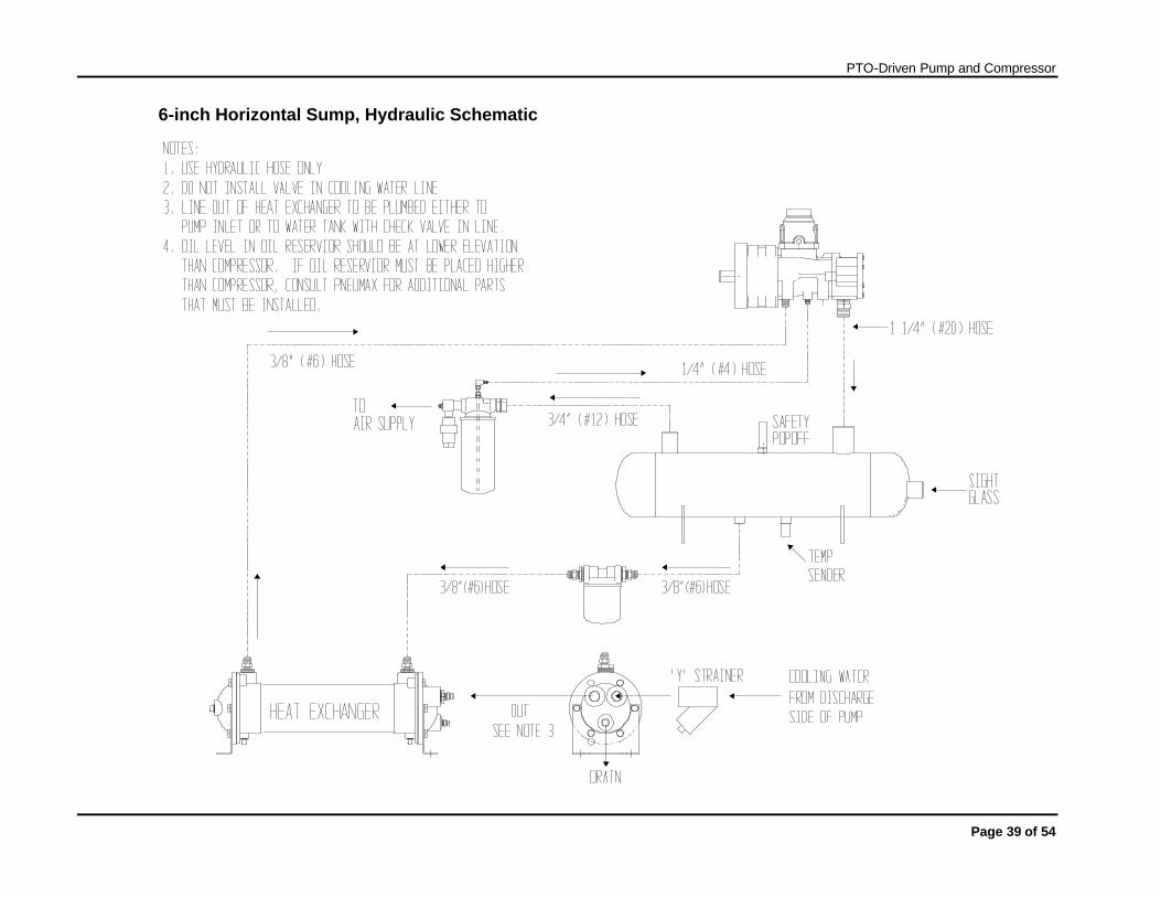
6-inch Horizontal Sump, Hydraulic Schematic
PTO-Driven Pump and Compressor
Page 40 of 54
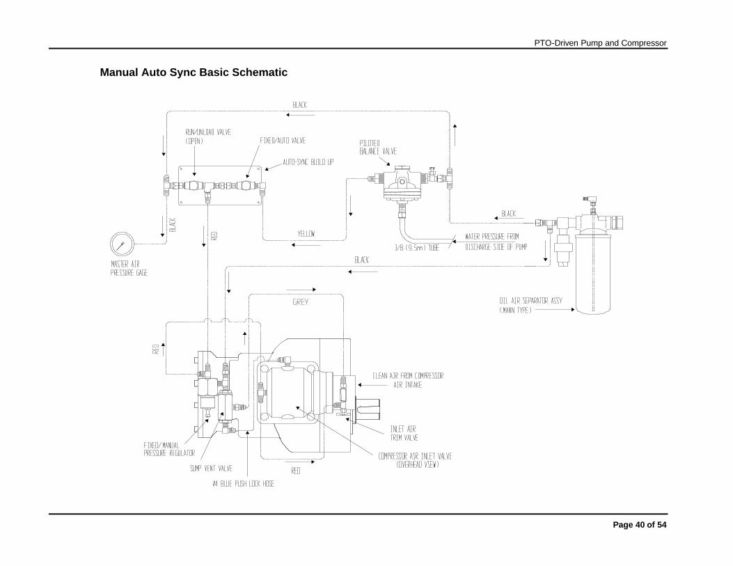
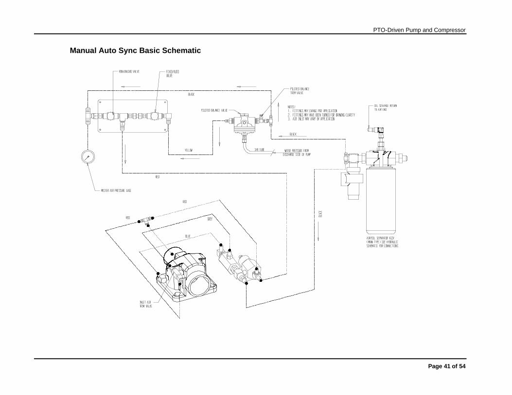
Manual Auto Sync Basic Schematic
PTO-Driven Pump and Compressor
Page 41 of 54
Manual Auto Sync Basic Schematic
PTO-Driven Pump and Compressor
Page 42 of 54
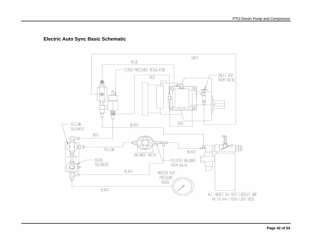
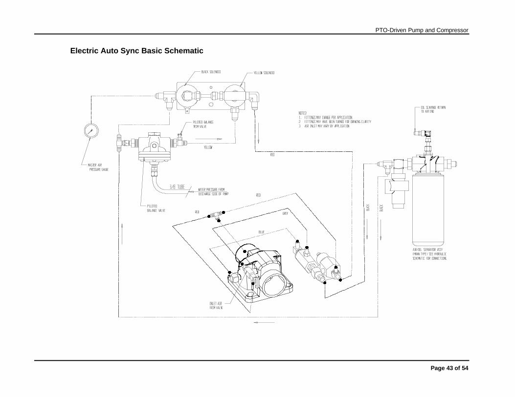
Electric Auto Sync Basic Schematic
PTO-Driven Pump and Compressor
Page 43 of 54
Electric Auto Sync Basic Schematic
PTO-Driven Pump and Compressor
Page 44 of 54
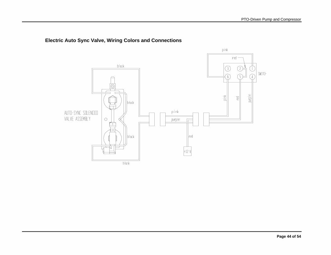
Electric Auto Sync Valve, Wiring Colors and Connections
PTO-Driven Pump and Compressor
Page 45 of 54
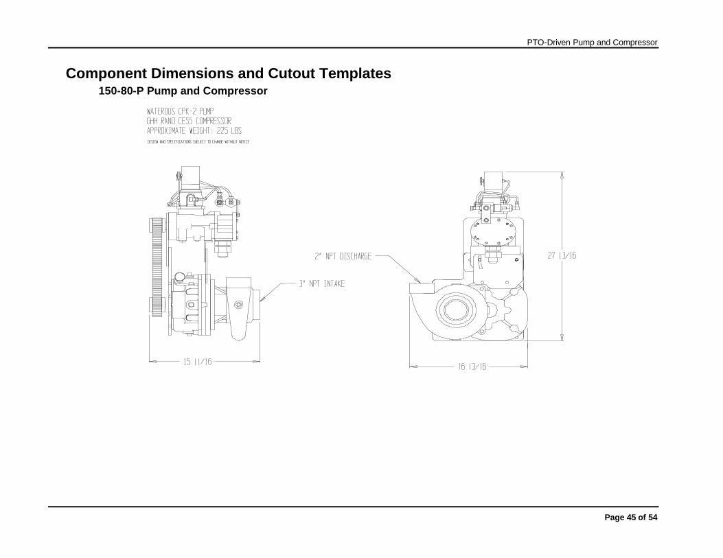
Component Dimensions and Cutout Templates 150-80-P Pump and Compressor
PTO-Driven Pump and Compressor
Page 46 of 54
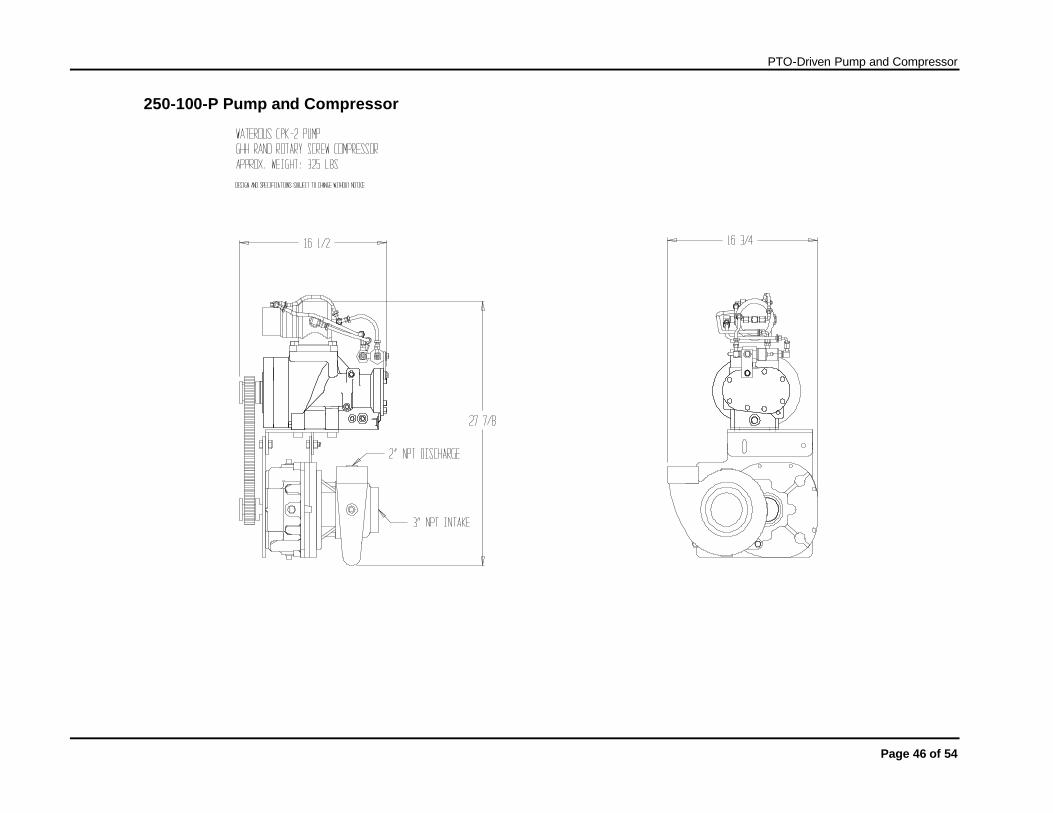
250-100-P Pump and Compressor
PTO-Driven Pump and Compressor
Page 47 of 54
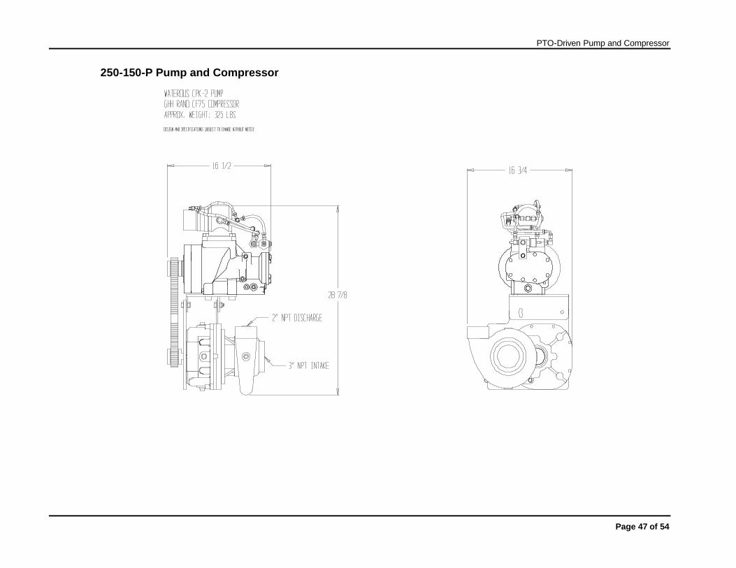
250-150-P Pump and Compressor

PTO-Driven Pump and Compressor
Page 48 of 54
500-150-P Pump and Compressor

PTO-Driven Pump and Compressor
Page 49 of 54
500-150-P2 Pump and Compressor

PTO-Driven Pump and Compressor
Page 50 of 54
6-inch T-sump
PTO-Driven Pump and Compressor
Page 51 of 54
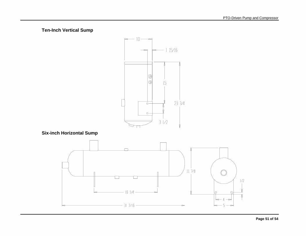
Ten-Inch Vertical Sump
Six-inch Horizontal Sump
PTO-Driven Pump and Compressor
Page 52 of 54
100-150 CFM Heat Exchanger (Oil cooler)
80 CFM Heat Exchanger (Oil cooler)
PTO-Driven Pump and Compressor
Page 53 of 54
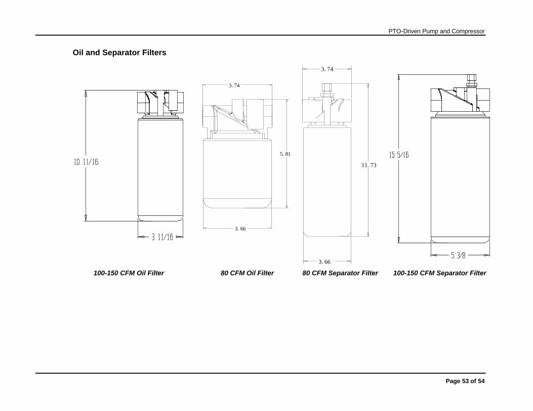
Oil and Separator Filters
3.66
3.74
5.81
3.66
3.74
11.73
100-150 CFM Oil Filter 80 CFM Oil Filter 80 CFM Separator Filter 100-150 CFM Separator Filter
PTO-Driven Pump and Compressor
Page 54 of 54
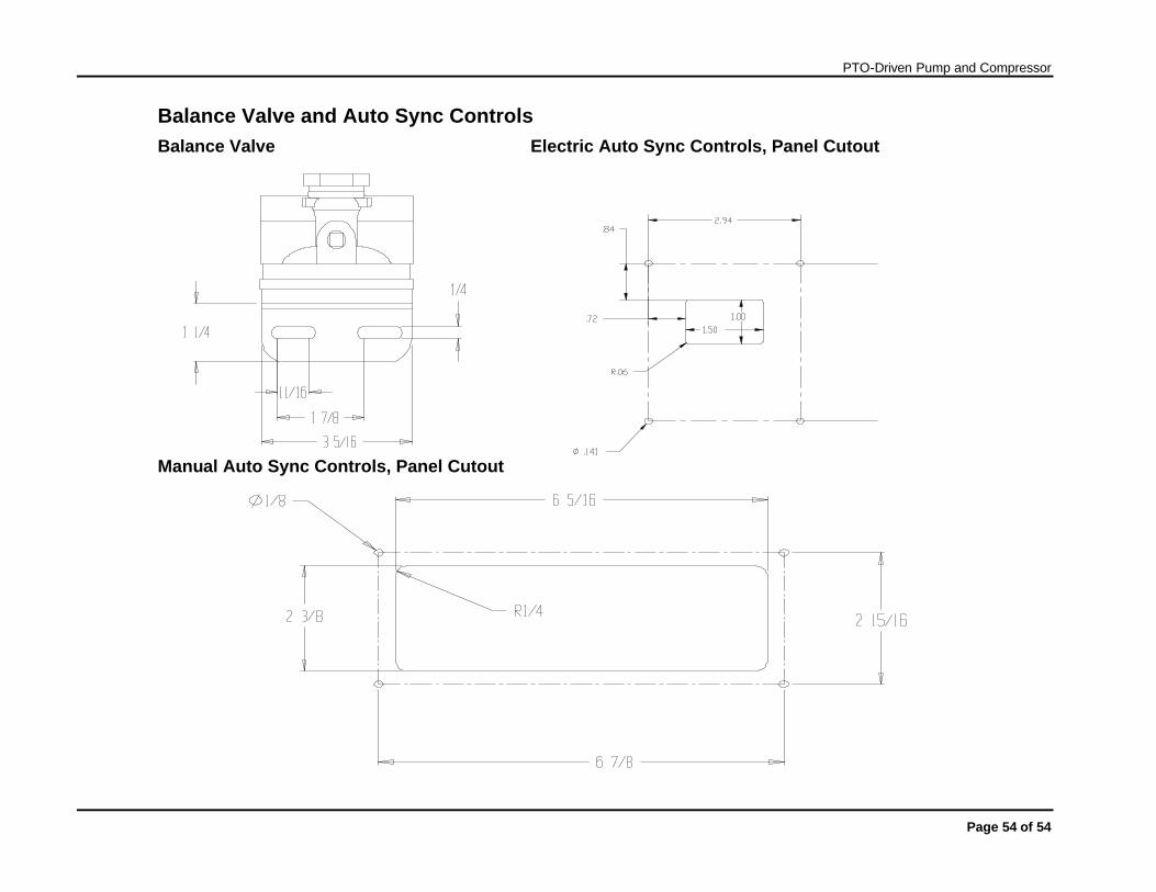
Balance Valve and Auto Sync Controls Balance Valve Electric Auto Sync Controls, Panel Cutout
Manual Auto Sync Controls, Panel Cutout
Related Documents


![PRED-03A W AIR CHANGES - JME Engineeringjmeengineering.com.au/images/pdf/PREDATOR_COMPRESSOR[1].pdf · PREDATOR COMPRESSOR: 1-1 PTO AIR COMPRESSOR 99904281 ... gauges as needed to](https://static.cupdf.com/doc/110x72/5a7870ce7f8b9aa2448bfd13/pred-03a-w-air-changes-jme-engin-1pdf-predator-compressor-1-1-pto-air-compressor.jpg)