PTG2000 System Power Generation, Transmission and Grid Modular System

Welcome message from author
This document is posted to help you gain knowledge. Please leave a comment to let me know what you think about it! Share it to your friends and learn new things together.
Transcript

PTG2000 SystemPower Generation, Transmission
and Grid Modular System

PTG2000 Power Generation, Transmission and Grid Modular System
2
ContentPTG2000 System, General Description and standards.......................................................................3
PTG2000 Power Generation, Transmission and Grid Modular System ..........................................4,5
PTG2000 System Level 1, 2 and 3.................................................................................................6-8
PTG1305 Mobile Motor / Generator Unit.......................................................................................9,10
PTG1965 Transformer Module..........................................................................................................11
PTG1520, -1521, -1522, -1523 Transmission / Distribution OH Line Model.........................................12
PTG1450 Line Multi Protection Trainer...............................................................................................13
PTG1455 Differential Relay Trainer..................................................................................................14
PTG1560 Resistive Load Module.....................................................................................................15
PTG1561 Inductive Load................................................................................................................15
PTG1562 Capacitor Load Module....................................................................................................15
PTG1565 Double Busbar.................................................................................................................16
PTG2216 Renewable Power Interface Module................................................................................16
PTG1439 Power Factor Control Module..........................................................................................17
PTG1570 Fault Connection Module.................................................................................................18
PTG1631 SCADA System Module...................................................................................................19
PTG2291 Solar Power Module.........................................................................................................20
PTG2290 Wind Mill..........................................................................................................................20
PTG1939 Power Energy Meter..........................................................................................................21
DMC9 Digital Multimeter..................................................................................................................22
MAT220349 Digital Clamping Meter..................................................................................................22
MV1103 Variable Transformer 3-phase............................................................................................23
MV1429 Connection Box /Terminal Board........................................................................................23
MV1904 Flex Stand..........................................................................................................................23
MV1801-HF Flex Set 200 pc Safety Leads 5 colours.........................................................................23
TERCO reserves the right to make changes in the design and modifications or improvements of the products at any time without incurring any obligations

PTG2000 Power Generation, Transmission and Grid Modular System
3
General DescriptionThe system consists of equipment that together form a mini power system showing how the power system works from production to consumer. The electric power system has two voltage sources consisting synchronous generator and one from the existing power distribution network.
Furthermore, one or more transformers can be used to connect the generator and load points to the mains. The switchgear has dual buses and three feeders for incoming and outgoing lines.
The system can be connected to renewable energy sources (solar and wind) via a grid inverter. At this point, it is also possible to connect three or sin-gle-phase loads.
The PTG1450 Line Multi Protection Trainer is equipped with the fully IEC61850 compliant ABB pro-tection REF630 which is one of the most modern and sophisticated protection units in the product family of Intelligent Electronic Devices (IEDs).
The use of a highly advanced IED enables great pos-sibilities to perform a wide range of laboratory experiments. This unit is intended for advanced training in modern line distance protection technology.
Note the difference in colour marking of phases and neutral conductors according to International Standards
EU ASIA, Middle East
Brown
Black
Grey
Blue
Red
Yellow
Blue
Black
Colouring of safety connections
Features
• Multiple Generators are possible. Motor 2.2 kW, Generator 1.2 kW• Active Load Sharing• Grid System• Colour coded power inlet / outlets for
easy recognizing• Mimic diagrams on the panels• Solar Simulation 0,3 kW• Basic and Advanced Relay Protection• Power Factor Control of Transmission
Lines• Fully IEC61850 compliant ABB Relays
Monitoring and control of the modules are connected in a Local Area Network.
Power supply and communication of modules
The unit is equipped with a large graphical Human Machine Interface (HMI) with a single line diagram.
Control, monitoring and parameter setting can be performed either from the HMI or from a PC by means of the standardized Ethernet interface.
The unit is equipped with a large graphical Human Machine Interface (HMI) with a single line diagram. Control, monitoring and parameter setting can be performed either from the HMI or from a PC by means of the standardized Ethernet interface.
The modules Power Sup-ply can be daisy-chained so that only one Power outlet is required
Every Module has two 1A fuse for Power Supply of the Module

PTG2000 Power Generation, Transmission and Grid Modular System
4
Pow
er S
yste
m O
verv
iew

PTG2000 Power Generation, Transmission and Grid Modular System
5
Diff
eren
tial R
elay
Tra
iner
pag
e 14
Line
Mul
ti P
rote
ctio
n pa
ge 1
3
Dou
ble
Bus
bar
page
16
AC
Pow
er E
nerg
y M
eter
spa
ge 2
1
Mob
ile M
otor
/ G
ener
ator
Uni
tpa
ge 9
,10
G
PTG
2000
Pow
er G
ener
atio
n, T
rans
mis
sion
and
Grid
Mod
ular
Sys
tem
R, L
, C L
oads
page
15
LAN
net
wor
k fo
r: •
SC
AD
A co
ntro
l and
mon
itorin
g•
Dis
turb
ance
Rec
ord
Ana
lysi
s vi
a P
C
π Li
ne p
age
12
Ren
ewab
le P
ower
Inte
rface
page
16
Faul
t Con
nect
ion
page
18
SC
AD
A pa
ge 1
9R
enew
able
Pow
er In
terfa
cepa
ge 1
6
Tran
sfor
mer
page
11
π C
able
pag
e 12
π Li
ne p
age
12
Pow
er F
acto
r Con
trol p
age
17
π Li
ne p
age
12

PTG2000 Power Generation, Transmission and Grid Modular System
6
Content in PTG2000 Level 1 with Variable Transformer and Connection Box
1
2
3
4
5
6
9
7
8
12
11
10
14
13
35
9
7 8
12
10
1
2
4 6
MV1103 Variable Transformer 3-phase
MV1429 Connection Box / Terminal Board
PTG1965 Transformer Module
PTG1521 Transmission HV OH-Line 230 kV, 100 km
PTG1523 Transmission HV OH-Line 35 kV, 20 km
PTG1450 Differential Relay Trainer
PTG1570 Fault Connection Module
PTG1560 Resistive Load Module 400V, 1,5 kW in 15 steps
PTG1561 Inductive Module 400V, 2,5 kVAr in 15 steps
PTG1562 Capacitor Load Module 400V, 2,8 KVAr in 15 steps
PTG1939 AC Power Energy Meter
DMC9 Digital Multimeter
DT-2330 Digital Clamp Meter AC / DC current
MV1801-HF Flex Set 200 pc Safety Leads 5 colours
MV1904 Flex Stand15
1111
13
15
14
PTG2000 Level 1, 2 and 3 are examples of standard setup.For more information about content and setup of your own
Laboratory, please contact us.

PTG2000 Power Generation, Transmission and Grid Modular System
7
Content in PTG2000 Level 2 with Mobil Motor/Generator Module
1513
9
7
8
10
4
6
12
3 5 7 1111
1
2
3
4
5
6
9
7
8
12
11
10
14
13
PTG1305 Mobil Motor / Generator Module
PTG1965 Transformer Module
PTG1521 Transmission HV OH-Line 230 kV, 100 km
PTG1523 Transmission HV OH-Line 35 kV, 20 km
PTG1450 Differential Relay Trainer
PTG1570 Fault Connection Module
PTG1565 Double Busbar Module with 4 feeders
PTG1560 Resistive Load Module 400V, 1,5 kW in 15 steps
PTG1561 Inductive Module 400V, 2,5 kVAr in 15 steps
PTG1562 Capacitor Load Module 400V, 2,8 KVAr in 15 steps
PTG1939 AC Power Energy Meter
DMC9 Digital Multimeter
DT-2330 Digital Clamp Meter AC / DC current
MV1801-HF Flex Set 200 pc Safety Leads 5 colours
MV1904 Flex Stand15
12 14
PTG2000 Level 1, 2 and 3 are examples of standard setup.For more information about content and setup of your own
Laboratory, please contact us.

PTG2000 Power Generation, Transmission and Grid Modular System
8
Content in PTG2000 Level 3 Extended and Advanced System
19
21
20
15
16
18
17
20
12
6
57
8
3
4 9
10
11
3
1212
13
16
201717
18
19
14
21
1
2
3
4
5
6
9
7
8
12
11
10
14
13
PTG1305 Mobil Motor / Generator Module
PTG1965 Transformer Module
PTG1521 Transmission HV OH-Line 230 kV, 100 km
PTG1523 Transmission HV OH-Line 35 kV, 20 km
PTG1522 Transmission Cable MV Line 11 kV, 5km
PTG1450 Line Multi Protection Trainer
PTG1450 Differential Relay Trainer
PTG1570 Fault Connection Module
PTG1560 Resistive Load Module 400V, 1,5 kW in 15 steps
PTG1561 Inductive Module 400V, 2,5 kVAr in 15 steps
PTG1562 Capacitor Load Module 400V, 2,8 KVAr in 15 steps
PTG1565 Double Busbar Module with 4 feeders
PTG2216 Renewable Power Interface Module
PTG2291 Solar Power Module (incl. stand for outdoor use)
PTG2290 Wind Mill Module (incl. Wind Mill for outdoor operation)
PTG1439-405 Power Factor Control Module
PTG1939 AC Power Energy Meter
DMC9 Digital Multimeter
DT-2330 Digital Clamp Meter AC / DC current
MV1801-HF Flex Set 200 pc Safety Leads 5 colours
MV1904 Flex Stand
15
PTG2000 Level 1, 2 and 3 are examples of standard setup. For more information about content and setup of your own Laboratory, please contact us.

PTG2000 Power Generation, Transmission and Grid Modular System
9
PTG1305-405 Mobile Motor / Generator Unit A standard laboratory for power transmission normally consists of one or two generators, which are connected to one or more transmission links which finally reach transformers, distribution units and loads. For example, here can be seen turbine/generators in parallel on the same busbar, a synchronous machine used as a synchronous compensator in the middle of a line, a single generator unit and a heavy group of gen-erators.Energy transfer, load shedding, static and dynamic sta-bility at disturbances as well as sophisticated protection schemes can be studied under realistic forms. Not to forget compensation possibilities.Power and current paths in grid networks are complicated. The TERCO system will give understanding for this problem. Wide range of flexibility is achieved by the mobile generator station / synchronous alternator (compen-sator) PTG1305.Two sets of PTG1305-405 can operate as described or work in parallel.
Modes of OperationPTG1305-405 can also be used to compensate for system power characteristics (active and reactive) viaturbine speed and generator magnetisation.
Technical Specification Power Supply: Voltage 380-415 V AC 3-phFrequency 50 Hz/60HzMax current 16 A
Turbine/AC-machine freq.drive: Armature/stator Volt 323-528 V ACFrequency 47-63 HzArmature/stator current 3.4 AInput current 5.9 ARated output current 4.0 ARated output capacity 3.2 kVASpeed 0-1800 rpm
Speed control/ Speed 0-1800 rpmActive power control: Frequency converter, electronic current limit setting, start- and stop ramps.Feedback systems Manual frequency setting. Automatic/Constant settingField current supply Integrated
Synchronous generator: Armature volt 0-140 / 240 V ACPower 1.2 kVACos φ 0.8Field volt 0-230 V DC
Voltage control/Reactive power control PWM min. ripple-converter, electronic current limit settingFeedback systems Manual voltage setting. Automatic/Constant setting. Separate voltage feedback
PTG1305-405 Mobile Motor / Generator Unit

PTG2000 Power Generation, Transmission and Grid Modular System
10
Instruments:AC-machine freq.drive (Turbine simulator)Parameters and indications selected by 4-lines display in HMI-unit for example:• Frequency setpoint 50Hz• Stator Electric Frequency 50Hz• Actual motor speed (from encoder) 1500 rpm at 50Hz, 1800 rpm at 60Hz• Motor current 2,20 A• DC-interlink voltage 520 V• Speed control potentiometer (=frequency control)• Feedback selector (Auto/ Man)
AC-machine M/G • Armature voltage• Voltage selector switch• Armature current• Voltage control potentiometer• Feedback selector (Auto/ Man)• Field current ammeter
Synchronizing device • Synchronizing instrument• Double voltmeter Du• Double frequency meter Df• Synchronizing switch• Automatic or manual synchronizing
Auxiliary • Machines mounted on machine bed with Slidrails. • Control panel integrated with machines to one mobile unit. • Laboratory connections by 4 mm safety plugs. Possibilities of connecting different
types of step-up transformers as well as other instruments and protections.
Dimensions 1550 x 800 x 1200 mmWeight 200 kg (approx.)
Item Power Supply Synchronous GeneratorPTG1305-405-235 400V 3-ph, 50Hz 230V 3-ph, 50HzPTG1305-406-236 400V 3-ph, 60Hz 230V 3-ph, 60HzPTG1305-405-405 400V 3-ph, 50Hz 400V 3-ph, 50Hz
PTG1305-406-406 400V 3-ph, 60Hz 400V 3-ph, 60Hz
The Mobile Motor / Generator Module is equipped with Local Area Network communication for monitoring via PTG1631 SCADA Module. Relevant faults can be connected for troubleshooting exercises via PTG1570 Fault Module
Voltage and frequency variants
Continued from previous page
PTG1305-405 Mobile Motor / Generator Unit

Transformer, Transmission
11
PTG1965 Transformer ModuleBetween the grid and generator station connects a generator. The transformer allows the user to configure the transformer with different vector groups such as Dyn / Yyn and so forth.
Power Supply: 1-ph 220 - 240 V, 50 - 60 HzThree-phase: 2 kVA, 50-60 HzPrimary: 3 x 230V D, 3 x 400V, YSecondary: 3 x 380-400-420V, y
Secondary current: 2.9ANo load current: 0.25AUk: 3.7%Losses: Po=40W, Pcu=107W
Vector group: Selectable
Dimension: 600 x 420 x 420 mmWeight: 48 kg
Transformer
Transformer, Transmission
12
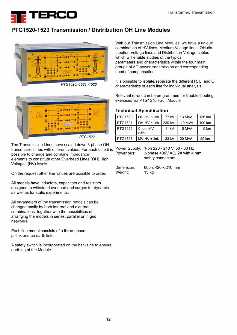
With our Transmission Line Modules, we have a unique combination of HV-lines, Medium-Voltage lines, OH-dis-tribution Voltage lines and Distribution Voltage cables which will enable studies of the typical parameters and characteristics within the four main groups of AC-power transmission and corresponding need of compensation.
It is possible to isolate/separate the different R, L, and C characteristics of each line for individual analysis.
Relevant errors can be programmed for troubleshooting exercises via PTG1570 Fault Module
Technical SpecificationPTG1520 OH-HV π-link 77 kV 13 MVA 136 kmPTG1521 OH-HV π-link 230 kV 110 MVA 100 kmPTG1522 Cable MV
π-link 11 kV 5 MVA 5 km
PTG1523 MV-HV π-link 33 kV 20 MVA 20 km
Power Supply: 1-ph 220 - 240 V, 50 - 60 HzPower bus: 3-phase 400V AC/ 2A with 4 mm safety connectors.
Dimension: 600 x 420 x 210 mmWeight: 15 kg
PTG1520-1523 Transmission / Distribution OH Line Modules
The Transmission Lines have scaled down 3-phase OH transmission lines with different values. For each Line it is possible to change and combine impedance elements to constitute other Overhead Lines (OH) High Voltages (HV) levels.
On the request other line values are possible to order. All models have inductors, capacitors and resistors designed to withstand overload and surges for dynamic as well as for static experiments.
All parameters of the transmission models can be changed easily by both internal and external combinations, together with the possibilities of arranging the models in series, parallel or in grid networks.
Each line model consists of a three-phase pi-link and an earth link.
A safety switch is incorporated on the backside to ensure earthing of the Module
PTG1520,-1521,-1523
PTG1522
Protective Relays
13
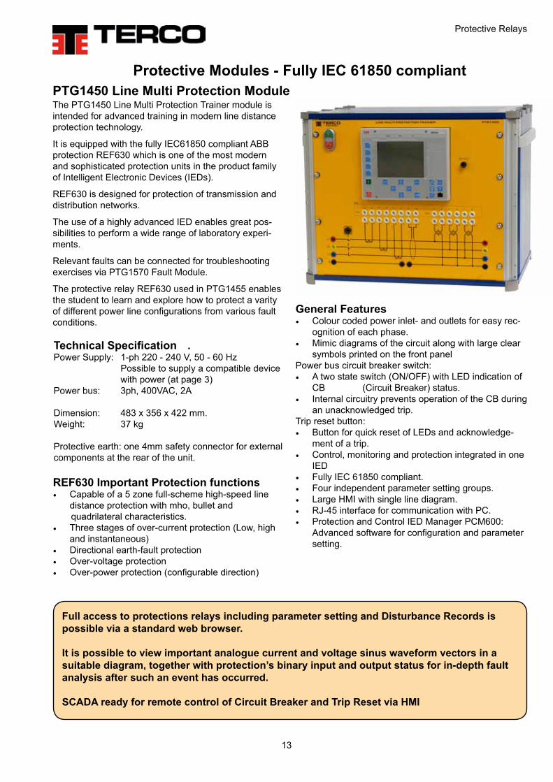
PTG1450 Line Multi Protection Module
Technical Specification .Power Supply: 1-ph 220 - 240 V, 50 - 60 Hz Possible to supply a compatible device with power (at page 3)Power bus: 3ph, 400VAC, 2A
Dimension: 483 x 356 x 422 mm. Weight: 37 kg
Protective earth: one 4mm safety connector for external components at the rear of the unit.
REF630 Important Protection functions• Capable of a 5 zone full-scheme high-speed line
distance protection with mho, bullet and quadrilateral characteristics.• Three stages of over-current protection (Low, high
and instantaneous)• Directional earth-fault protection• Over-voltage protection• Over-power protection (configurable direction)
Protective Modules - Fully IEC 61850 compliant
The PTG1450 Line Multi Protection Trainer module is intended for advanced training in modern line distance protection technology.
It is equipped with the fully IEC61850 compliant ABB protection REF630 which is one of the most modern and sophisticated protection units in the product family of Intelligent Electronic Devices (IEDs).
REF630 is designed for protection of transmission and distribution networks.
The use of a highly advanced IED enables great pos-sibilities to perform a wide range of laboratory experi-ments.
Relevant faults can be connected for troubleshooting exercises via PTG1570 Fault Module.
The protective relay REF630 used in PTG1455 enables the student to learn and explore how to protect a varity of different power line configurations from various fault conditions.
Full access to protections relays including parameter setting and Disturbance Records is possible via a standard web browser.
It is possible to view important analogue current and voltage sinus waveform vectors in a suitable diagram, together with protection’s binary input and output status for in-depth fault analysis after such an event has occurred.
SCADA ready for remote control of Circuit Breaker and Trip Reset via HMI
General Features• Colour coded power inlet- and outlets for easy rec-
ognition of each phase.• Mimic diagrams of the circuit along with large clear
symbols printed on the front panelPower bus circuit breaker switch: • A two state switch (ON/OFF) with LED indication of
CB (Circuit Breaker) status. • Internal circuitry prevents operation of the CB during
an unacknowledged trip.Trip reset button: • Button for quick reset of LEDs and acknowledge-
ment of a trip.• Control, monitoring and protection integrated in one
IED• Fully IEC 61850 compliant.• Four independent parameter setting groups.• Large HMI with single line diagram.• RJ-45 interface for communication with PC.• Protection and Control IED Manager PCM600:
Advanced software for configuration and parameter setting.

Protective Relays
14
The PTG1455 Differtial Relay Module module is intended for advanced training in modern differential protection technology.
It is equipped with the fully IEC61850 compliant ABB RET615 protective relay which is one of the most sophisticated protection unit in the product family of intelligent electronic devices (IEDs).
RET615 is designed for differential protection of trans-formers, generators, line sections and their combina-tions.
The use of a highly advanced IED enables great possibilities to perform a wide range of laboratory experiments.
Relevant faults can be connected for troubleshooting exercises via PTG1570 Fault Module.
The protective relay RET615 used in PTG1455 enables the student to learn and explore how to protect a variety of different power transformer connections with a differential protection scheme.
PTG1455 Differential Relay Module
Technical SpecificationPower Supply: 1-ph 220 - 240 V, 50 - 60 Hz Power bus: (3-ph) 400V AC/ 2A with 4 mm safety connectors
Dimension: 357 x 483 x 420 mmWeight: 37 kg
Protective earth: one 4mm safety connector for external components at the rear of the unit.
General Features• Colour coded power inlet- and outlets for easy
recognition of each phase.• Mimic diagrams of the circuit along with large clear
symbols printed on the front panel.Power bus circuit breaker switch: • A two state switch (ON/OFF) with LED indication of
CB (Circuit Breaker) status. • Internal circuitry prevents operation of the CB during
an unacknowledged trip.Trip reset button: • Button for quick reset of LEDs and acknowledge-
ment of a trip.• Control, monitoring and protection integrated in one
IED• Fully IEC 61850 compliant.• Four independent parameter setting groups.• Large HMI with single line diagram.• RJ-45 interface for communication with PC• Three power lines; 1 incoming power line and 2
outgoing. Each line contain three phases L1, L2, L3 and Neutral wire.
• 12 Current Transformers which enables the student to study various CT-connections.
• Protection and Control IED Manager PCM600: Advanced software for configuration and parameter setting.
• Front panel switches that enable the student to test differential protection on a double-busbar.
RET615 Important Protection Functions• Differential Fault Protection• Three-phase non-directional overcurrent protection,
low, high and instantaneous stage• Non-directional earth-fault protection, low and high
stage• Negative-sequence overcurrent protection• Residual overvoltage protection
Full access to protections relays including parameter setting and Disturbance Records is possible via a standard web browser.
It is possible to view important analogue current and voltage sinus waveform vectors in a suitable diagram, together with protection’s binary input and output status for in-depth fault analysis after such an event has occurred.
SCADA ready for remote control of Circuit Breaker and Trip Reset via HMI

Loads
15
PTG1562 Capacitor Load Module
PTG1560 Resistive Load ModuleThe load can be changed in 15 steps with 100W / step at 400V. The unit can be programmed for a typical load curve over 24 hours.
Power Supply: 1-ph 220 - 240 V, 50 - 60 HzInput Voltage: 3-phase 400V AC/ 2A with 4 mm safety connectors.Dimension: 600 x 420 x 420 mmWeight: 38 kg
PTG1560 consists of 2 units which can be split to opti-mize the bench top place.
GeneralPTG1561 is housed in a metal cabinet with electrical data and symbols on the front panel. Both the 50 and 60Hz variants charge 1.5 kVAr and are Y-connected.
PTG1561 Inductive Load for 50 / 60HzPower Supply: 1-ph 220 - 240 V, 50 - 60 HzCurrent: 0.15-2.2A / 0.12-1.8 AInput Voltage: 3-phase 400V 50Hz / 2A with 4 mm safety connectors
Dimension: 600 x 420 x 210 mmWeight: 40 kg
PTG1560 consists of 2 units which can be split to opti-mize the bench top place.
PTG1561 Inductive Load
Loads
GeneralPTG1562 is housed in a metal cabinet with electrical data and symbols on the front panel. Both the 50 and 60Hz variants charge 1.5 kVAr and are Y-connected.
PTG1562 Capacitive Load for 50Hz / 60HzPower Supply: 1-ph 220 - 240 V, 50 - 60 HzCurrent: 0.15-2.2A / 0.18-2.6AInput Voltage: 3-phase 400V 50Hz / 2A with 4 mm safety connectors
Dimension: 600 x 420 x 210 mmWeight: 15 kg
All Load Modules is equipped with Local Area Network communication for monitoring and control via PTG1631 SCADA Module.
Relevant errors can be programmed for troubleshooting exercises via PTG1570Fault Module

16
Power Components, Renewable Energy
PTG1565 Double Busbar ModuleThis unit is a double busbar module where the user has access to 4 feeders for incoming/outgoing power. Each feeder is connected to the two busbars through two isolators and one circuit breaker. Internal logic prohibits the user from incorrect switching (i.e breaking current with an isolator). This module can be used in the laboratory to assemble a larger power grid.
Relevant faults can be connected for troubleshooting exercises via PTG1570 Fault Module
Power Supply: 1-ph 220 - 240 V, 50 - 60 HzPower bus: 3-phase 400V AC/ 2A with 4 mm safety connectors.
Size: 600 x 420 x 210 mmWeight: 10 kg
PTG2216 Renewable Power Interface ModuleThis unit is used whenever a solar panel is to be integrated to a power grid. The unit contains a grid-tie inverter which converts the DC power into AC 230V/50 Hz synchronized to the grid.Power Supply: 1-ph 220 - 240 V, 50 - 60 HzPower bus: 1-phase 230V AC/ 2A with 2 mm safety connectors.
• Three-phase network analyzer• Grid-tie inverter for connecting renewable energy
(DC-source) to grid• DC-breaker• AC-breaker• Anti-islanding protection• Two outgoing AC feeders, one for grid connection
and one for direct connection to loads
Relevant faults can be connected for troubleshooting exercises via PTG1570 Fault Module
Dimension: 600 x 420 x 210 mmWeight: 10 kg
Power Components
Renewable Energy
All Load Modules is equipped with Local Area Network communication for monitoring and control via PTG1631 SCADA Module.
Relevant errors can be programmed for troubleshooting exercises via PTG1570Fault Module

Power Factor Control
17
General
With the Power Factor Control Module (PFC) you can minimise the currents caused by reactive losses of power thereby optimising the transfer of energy be-tween generation and loading.
This is becoming more and more important today when “Saving energy” is vital in a world with focus on pollution and shortage of energy.
Field of applicationInductive or mixed inductive and resistive networks in need of compensation, for example when starting and running induction motors as in industrial applications.
Principles of operationDepending on the power factor of the loading network a microprocessor will connect groups of capacitors.By measuring phase voltages and current the micropro-cessor will calculate how many capacitive groups that has to be connected and also in which combinations.
Electrical detailsNumber of 3-ph groups 6 Power factor setting 0.7 inductive to 0.7 capacitiveNominal voltage 3 x 400 V 50 – 60 Hz Nominal power 0 – 2 kVAr cap.PF-Controller Automatic or manual Adjustable delay times, switch- ing sequences and strategies.
Monitoring and Measurement on the controller: Voltage, Current and Power factorSwitching modes: Linear and circularIndication lamps: Indication lamps for the capacitor groups which are connected
Physical designThe Power Factor Control Unit is housed in a sturdy apparatus box with a clear mimic diagram explaining how to connect the supplying net from the left to the right side where the network in need for power factor compensation is connected.Readings, parameters and sub parameters are indicat-ed on the front of the controller. Other settings and pro-gramming than the defaults are simply performed from the keyboard and displayed on the controller front.
General data:Power supply: 1-ph 220 - 240 V, 50 - 60 HzDimension: 510 x 570 x 280 mmWeight 24 kg
Typical Experiments with Terco PFC:• The concept of active power, apparent power and reactive power• The concept of power factor and cos φ• The concept of measuring methods• Start current settings (C/k)• Delay times • Efficiency and losses• Linear and circular switching modes• PF-Controller design and schematics • Programming the controller• PF-Controller and resistive/inductive loads• PF-Controller and induction motor loads• Control range limits
PTG1439-405 Power Factor Control Unit
Fault Connection
18
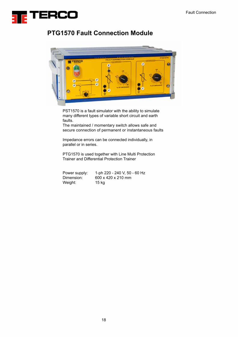
PST1570 is a fault simulator with the ability to simulate many different types of variable short circuit and earth faults.The maintained / momentary switch allows safe and secure connection of permanent or instantaneous faults
Impedance errors can be connected individually, in parallel or in series.
PTG1570 is used together with Line Multi Protection Trainer and Differential Protection Trainer
Power supply: 1-ph 220 - 240 V, 50 - 60 HzDimension: 600 x 420 x 210 mmWeight: 15 kg
PTG1570 Fault Connection Module

SCADA
19
PTG1631 SCADA SystemPTG1631 SCADA System Module includes an ad-vanced and stylish industrial standard HMI where measurement data from throughout the power system is collected, logged and presented.
Power system characteristics can be monitored and investigated in real-time on attractive virtual instru-ments. Time-lapse data tracked and presented clearly in trend charts and values stored in the data logger can be saved and exported for further investigation at a later date.
Clear indications of important system events help oper-ators to understand the complicated relationships and balance required between modern components, in order to maintain a robust power supply.
PTG1631 SCADA System Module is designed to work with multiple PTG1939 Power Energy Meters. These measurement instruments provide information of over 30 3-phase parameters each and are connected via a LAN network.
The HMI can even be accessed and controlled remotely from a PC via a VNC Viewer. This allows for further pres-entation via projector, large-screen t.v. or other device.
Technical specificationsHMIHousing material: Powder-coated aluminum, Gray Screen: TFT-LCD 12”, 1280x800 px Class I (ISO9241-307) LED Backlight and Industrial dimming Resistive Touch Screen Full colour
Power supply: 1-ph 220 - 240 V, 50 - 60 HzDimension: 510 x 570 x 280 mmWeight 17 kg
SCADA System

Solar Panel and Wind Mill
20
PTG2291 Solar PanelMaximum Power: 265WMaximum Power Voltage: 30.7VMaximum Power Current: 8.63AOpen Circuit Voltage: 38.5VShort Circuit Current: 9.1AMaximum System Voltage: DC 1000VIrradiance: 1000W/m2
Dimension: 1650 x 990 x 120 mm Dimension specifies panel folded down.Weight: 22 kg
PTG2290 Wind MillThe Wind Mill consists of a wind turbine in miniature placed outdoors. A number of sensors to be installed which enables the user to collect data on wind speed, wind direction, temperature and pressure.
Similar to the solar module is an electricity meter in-stalled at the turbine output for measuring the voltage, current and power directly from the generator.All data is logged with data acquisition equipment, and can then be presented on a computer screen.
Technical SpecificationsSwept area 1.07 m2Rotor diameter 1.17 mWeight 5.9 kgVoltage 12, 24 och 48 VDCTurbine Controller Microprocessor basedRotor Brushless Permanent Magnetized SG
Maximal Wind speed 49.2 m/s

Instruments
21
PTG1939 Power Energy Meter is a practical solution for the study of 3-Phase AC power systems. A microprocessor-based energy meter provides the user with an instant overview of the relevant three or four-wire, 3-Phase network parameters in balanced or unbalanced networks.
The simplified connection process means your labora-tory experiments can be set up and taken down in just minutes, leaving more time to investigate and under-stand the characteristics and ambiguities of 3-Phase power networks.
Each line is fused with a 500V, 10A slow fuse and together with 10:1A current transformers provide a good level of protection against incorrect connection, mishan-dling and carelessness.
Technical specificationsPower supply 220VAC, 50/60HzMeasurementVoltage, V: 500VAC max VT ratio: Direct measurementCurrent, I: 10A maxActive power, P: 0.0…(+/-)1999.9 WApparent power, S: 0.0…(+/-)1999.9 VARective power, Q: 0.0…(+/-)1999.9 VArActive power factor, Pf: -1...cos φ…1Frequency, f: 15…500Hz
CommunicationsCommunication with SCADA via Local Area Network
Dimension: 255 x 195 x 335mmWeight: 10kg
PTG1939 Power Energy Meter
PTG1939 Power Energy Meter enables the measure-ment and visualisation of 46 power energy quantities and 25 harmonics for each phase of current and volt-age. The analyser can display parameters of interest in the study of symmetrical as well as non-symmetrical networks, such as: phase voltages, phase-to-phase voltages, line currents, phase active powers, phase reactive powers, phase apparent powers, phase active power factors, phase reactive/active power factors, mean three-phase voltage, mean phase-to-phase voltage, mean three-phase current, three-phase active, reactive and apparent powers, mean three-phase power factors.
The visualization of parameters is distributed over programmable pages (max 20 pages) where each page simultaneously displays four parameters.
Instruments

Instruments
22
MAT220349 Digital Clampmeter AC/DC current MAT229349 is a small and pliable clamp meter for AC and DC current up to 200 A. A clear and easy-to-read 3.5 digit LCD display with max reading of 1999.
The slim jaws have an inner diameter of 30 mm and is easy to fit in narrow places. The data-hold function freezes the value, and is useful when working in the dark or hard to get areas where you cannot see the LCD. The measuring values are updated 2 times / sec.MAT220349 is delivered with manual, battery and soft case. Conforms with IEC safety requirements. Specifications:• Current (AC): 0-20 A, 0-150 A, 150-199, 9A• Current (DC): 0 - 20 A, 0 - 150 A, 150 - 199, 9A• Low battery indication: ”B” mark on LCD• Power supply (battery): 2 pcs RS-44 or 2 pcs LR-44
DMC9 Digital Multimeter
High-resolution, 3-3/4 digit LCD, 4000-count autoranging• 7 functions / 23 ranges• Battery Test function with Go/NoGo LED indicator• Industry standard test leads, safety rated• Protective holster included Voltage• DC Voltage 400 mV, 4V, 40V, 400V, 600V• AC Voltage 400 mV, 40V, 400V, 600V Current• DC Current 40 mA, 400 mA, 8 A, (10A for 10 min)• AC Current 40 mA, 400 mA, 8 A, (10A for 10 min) Resistance• 400 Ohm, 4 kOhm, 40 kOhm, 400 kOhm, 4 MOhm, 40 MOhm. Buzzer SoundsDiode TestOverload Protection Included accessories: Protective holster, test leads, battery and users manual. Dimension: 140x78x5 mmWeight: 0.22 kg
Dimension: 20x44x146 mmWeight: 0.1 kg

PTG2000 Power Generation, Transmission and Grid Modular System
23
MV1103 Variable Transformer 3-phaseSupplied with a scale showing output voltage. Thermal overload protection for three output phases are placed on the front panel. A common shaft rotates all output voltage sliders in parallel. The unit is mobile on 4 wheels.
Input: 3 x 400 V, 8 A, 50-60 Hz Output: 3 x 0-450 V, 8 A
Dimension: 280 x 290 x 560 mm Weight: 34 kg
MV1429 Terminal BoardThe box has outlets (three phases, zero and earth) for labo-ratory leads with 4 mm diameter plug ins. These outlets are connected to a 5 x 2.5 mm2 cable with a 3-phase CEE plug rated 16A. The connection box is equipped with miniature circuit breakers for 16 A. Dimension: 250 x 240 x 75 mmWeight: 2.0 kg
MV1904 Flex Stand For suspension of laboratory flexes. The stand has 12 slots between parallel tubes with space for 10-15 laboratory flexes in each slot. Flexes of length 200 cm are suspended in a separate position above the stand. This rigid stand has a heavy steel plate pedestal.General Data Height: 1170 mm Weight: 9 kg
MV1801-HF Flex Set Area 1.5 mm2
Set of 200 leads in 5 different colours, red, yellow, blue, black, yellow/green, and 4 different lengths, 25, 50, 100 and 200 cm, 5 of each.
Laboratory Flexes with Safety Plugs, Fixed Sleeve

TERCO AB P.O. Box 5014SE-14105 HUDDINGESWEDEN
Office/Works: Pyramidbacken 6SE-141 75 KUNGENS KURVASTOCKHOLM
Phone: +46 8 506 855 00Fax +46 8 506 855 01e-mail [email protected] www.terco.se
Terco headoffice and factory outside Stockholm, Sweden
TERCO HEADOFFICE
TRAINING FOR TOMORROW´S WORLD
TERCO AB was founded in 1963 with the aim of producing and sup-plying practically oriented equipment for technical education.
TERCO develops, manufactures and markets advanced equipment and systems for technical education. TERCO is today represented in more than 50 countries world wide.
High Voltage
Process Control
Training
Energy
Furniture & Power Distribution
Mechatronics
Material Testing
Power Systems Electrical Machines & Drives
2018
-12-
03
Related Documents


