Pro Tools Expansion Chassis Guide Version 4.3 Digidesign Inc. 3401-A Hillview Avenue Palo Alto, CA 94304 tel: 650·842·7900 fax: 650·842·7999 Technical Support (USA) 650·842·6699 650·856·4275 Product Information 650·842·6602 800·333·2137 Fax on Demand 1-888-USE-DIGI (873-3444) World Wide Web www.digidesign.com Digidesign FTP Site ftp.digidesign.com

Welcome message from author
This document is posted to help you gain knowledge. Please leave a comment to let me know what you think about it! Share it to your friends and learn new things together.
Transcript
Pro ToolsExpansion Chassis Guide
Version 4.3
Digidesign Inc.3401-A Hillview Avenue
Palo Alto, CA 94304tel: 650·842·7900fax: 650·842·7999
Technical Support (USA)650·842·6699650·856·4275
Product Information650·842·6602800·333·2137
Fax on Demand1-888-USE-DIGI (873-3444)
World Wide Webwww.digidesign.com
Digidesign FTP Siteftp.digidesign.com
Copyright
This User’s Guide is copyrighted ©1998 by Digidesign, a division of Avid Technology, Inc. (hereafter “Digidesign”), with all rights reserved. Under copyright laws, this manual may not be duplicated in whole or in part without the written consent of Digidesign.
DIGIDESIGN, AVID and PRO TOOLS are trademarks or registered trademarks of Digidesign and/or Avid Technology, Inc. All other trademarks are the property of their respective owners.
All features and specifications subject to change without notice.
PN 932106388-00 REV A
contents
Introduction. . . . . . . . . . . . . . . . . . . . . . . . . . . . . . . . . . . . . . . . . . . . . . . . . . . . . . . . . . . . . 1
Installing Expanded Pro Tools 24 MIX systems . . . . . . . . . . . . . . . . . . . . . . . . . . . . . . . . . . . . 3
Pro Tools 24 MIX/MIXplus Expanded Systems without an Expansion Chassis. . . . . . . . . . . . . . . 4
Installing Expanded Pro Tools 24 MIXplus Systems with an Expansion Chassis . . . . . . . . . . . . . 6
Magma 7-slot. . . . . . . . . . . . . . . . . . . . . . . . . . . . . . . . . . . . . . . . . . . . . . . . . . . . . . . 11
Magma 13-slot. . . . . . . . . . . . . . . . . . . . . . . . . . . . . . . . . . . . . . . . . . . . . . . . . . . . . . 11
Installing Expanded Pro Tools 24 Systems . . . . . . . . . . . . . . . . . . . . . . . . . . . . . . . . . . . . . . 12
Pro Tools 24 Expanded Systems with an Expansion Chassis. . . . . . . . . . . . . . . . . . . . . . . . . . 14
Bit 3 Expansion Chassis (13 slot) . . . . . . . . . . . . . . . . . . . . . . . . . . . . . . . . . . . . . . . . 18
Installing Expanded Pro Tools III Systems. . . . . . . . . . . . . . . . . . . . . . . . . . . . . . . . . . . . . . . 22
Magma Expansion Chassis (7-slot) . . . . . . . . . . . . . . . . . . . . . . . . . . . . . . . . . . . . . . . 26
Contents iii

iv
Pro Tools 4.3 Expansion Chassis Guide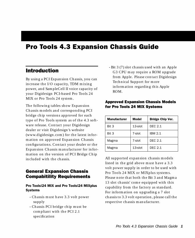
Pro Tools 4.3 Expansion Chassis Guide
IntroductionBy using a PCI Expansion Chassis, you can increase the I/O capacity, TDM mixing power, and SampleCell II voice capacity of your Digidesign PCI-based Pro Tools 24 MIX or Pro Tools 24 system.
The following tables show Expansion Chassis models and corresponding PCI bridge chip versions approved for each type of Pro Tools system as of the 4.3 soft-ware release. Contact your Digidesign dealer or visit Digidesign’s website (www.digidesign.com) for the latest infor-mation on approved Expansion Chassis configurations. Contact your dealer or the Expansion Chassis manufacturer for infor-mation on the version of PCI Bridge Chip included with the chassis.
General Expansion Chassis Compabitility Requirements
Pro Tools|24 MIX and Pro Tools|24 MIXplus Systems
- Chassis must have 3.3 volt power supply
- Chassis PCI bridge chip must be compliant with the PCI 2.1 specification
- Bit 3 (7) slot chassis used with an Apple G3 CPU may require a ROM upgrade from Apple. Please contact Digidesign Technical Support for more information regarding this Apple ROM.
Approved Expansion Chassis Models for Pro Tools 24 MIX Systems
All supported expansion chassis models listed in the grid above must have a 3.3 volt power supply in order to be used with Pro Tools 24 MIX or MIXplus systems. Please note that both the Bit 3 and Magma 13 slot chassis' come equipped with this capability from the factory as standard. For information on upgrading a 7 slot chassis to 3.3 volt operation, please call the respective chassis manufacturer.
Manufacturer Model Bridge Chip Ver.
Bit 3 13-slot DEC 2.1
Bit 3 7-slot IBM 2.1
Magma 7-slot DEC 2.1
Magma 13-slot DEC 2.1
Pro Tools 4.3 Expansion Chassis Guide 1
2
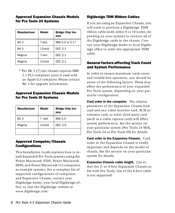
Approved Expansion Chassis Models for Pro Tools 24 Systems
* The Bit 3 (7) slot chassis requires IBM 2.1 PCI compliant parts if used with an Apple G3 computer. Please contact Bit 3 for upgrade information.
Approved Expansion Chassis Models for Pro Tools III Systems
Approved Computer/Chassis Configurations
This Installation Guide explains how to in-stall Expanded Pro Tools systems using the Power Macintosh 9500, Power Macintosh 9600, and Power Macintosh G3 computers as example systems. For a complete list of supported configurations of computers and Expansion Chassis, contact your Digidesign dealer, your local Digidesign of-fice, or visit the Digidesign website at www.digidesign.com.
Manufacturer Model Bridge Chip Ver-sion
Bit 3 7-slot IBM 2.0 or 2.1*
Bit 3 13-slot DEC 2.1
Magma 7-slot DEC 2.1
Magma 13-slot DEC 2.1
Manufacturer Model Bridge Chip Ver-sion
Bit 3 7 -slot IBM 2.0
Magma 13-slot DEC 2.0
Pro Tools 4.3 Expansion Chassis Guide
Digidesign TDM Ribbon Cables
If you are using an Expansion Chassis, you will need to purchase a Digidesign TDM ribbon cable (with either 8 or 10 nodes, de-pending on your system) to connect all of the Digidesign cards in the chassis. Con-tact your Digidesign dealer or local Digide-sign office to order the appropriate TDM cable.
General factors affecting Track Count and System Performance
In order to ensure maximum track count and trouble-free operation, you should be aware of the following factors. These may affect the performance of your expanded Pro Tools system, depending on your par-ticular configuration.
Card order in the computer. The relative placement of the Expansion Chassis host card and any video monitor card, SCSI ac-celerator card, or other third-party card (such as a video capture card) will affect system performance. See the section on your particular system (Pro Tools 24 MIX, Pro Tools 24 or Pro Tools III) for details.
Card order in the Expansion Chassis. Card order in the Expansion Chassis is vitally important and depends on the model of chassis. See the section on your particular system for details.
Expansion Chassis cable length. Use ei-ther the 2- or 4-foot Expansion Chassis ca-ble with Pro Tools. Use of the 6-foot cable is not supported.
Installing Expanded Pro Tools 24 MIX systemsThe compatibility and configuration infor-mation in this section applies to any Pro Tools system which includes a Pro Tools 24 MIX card (this includes the Pro Tools 24 MIX and Pro Tools 24 MIXplus systems).
Understanding Track Count and DSP Utilization in Expanded Pro Tools MIX and MIXplus Systems
When using Pro Tools 24 MIX-series hard-ware, you must always use a MIX Core card as your “master” audio card. This will be the card to which your primary audio in-terface is connected, and that audio inter-face becomes the clock master for your other audio interfaces.
The following explain what advantages you will gain by expanding your Pro Tools 24 MIX-based system.
By adding MIX Farm cards you can:• Increase the total amount of processing
available for Plug-Ins and Pro Tools mixer construction.– and –
• Increase total channel input and output by connecting an additional audio inter-face (not included with MIX Farm cards).
By adding MIX I/O cards, you can:• Increase the I/O capacity of your system
by connecting up to 16 channels of ad-ditional I/O to the MIX I/O card.– and –
• Maximize DSP resources - Pro Tools’ mixer will first use DSP on the MIX I/O
card before “claiming” any DSP from the MIX Core or Farm cards.
Pro Tools 24 MIX-series cards are fully compatible with Pro Tools 24-series d24 and DSP Farm cards. In such “mixed” sys-tems, voice count and “master” status is al-ways given to the MIX Core card, which provides up to 64 voices (the maximum number of voices in any Pro Tools 24 MIX or Pro Tools 24 system is 64). Configuring Pro Tools 24 MIX for 64-voice performance is described in your Pro Tools System In-stallation Guide.
If you are adding new Pro Tools 24 MIX hardware to an existing Pro Tools 24 system
If your system includes both Pro Tools 24 MIX and Pro Tools 24-series hardware, you will be able to take advantage of the ex-panded capabilities offered by each type of card. These expanded capabilities differ slightly from systems that do not include MIX-series hardware.
By adding a Pro Tools d24 Audio Card to your Pro Tools 24 MIX system, you can:• Increase total channel I/O
– and –• Maximize DSP resources - Pro Tools’
mixer will first use DSP on the d24 card before “claiming” any DSP from the MIX Core or Farm cards.
By adding a Pro Tools 24 PCI DSP Farm Card to your system, you can increase the DSP resources available for Plug-Ins, mix-ers, and I/O.
Pro Tools 4.3 Expansion Chassis Guide 3

4
About PCI Slots, Bus Masters, and Bridges - A Brief Introduction to Expanded Systems’ Theory and Operation
The PCI slots in your computer are grouped in banks of three, each controlled by a PCI Bridge Chip. A six-slot computer has two of these groups or bridges.
A bus master card is a PCI card that con-trols the data transfer to and from the bridge where it resides. Pro Tools 24 MIX cards act as bus masters.
Other cards that act as bus masters include:• Expansion Chassis host cards• SCSI Accelerator cards• Most video capture cards (Note: this
does not include video monitor cards, which are not bus masters).
When setting up any Pro Tools system, you must take care to install your PCI cards in your computer so that your Pro Tools card(s) are on a separate PCI bridge from other bus master cards.
When using an expansion chassis with a six-slot computer, you must place the chassis “host” card on a separate bridge from other bus master cards.
When using a SCSI accelerator, special care must be taken to make sure it is installed correctly for your set up.
✽ (Later in this guide are many example set-ups showing how to arrange all these various types of cards in typical Pro Tools systems.)
Consult the manufacturer of your third-party PCI cards to determine if they operate as bus masters.
Pro Tools 4.3 Expansion Chassis Guide
The following sections provide more infor-mation on correct card installation order, using currently supported CPUs as exam-ples.
Pro Tools 24 MIX/MIXplus Expanded Systems without an Expansion ChassisWith Pro Tools 24MIX and MIXplus, it is possible to install as many as four Pro Tools cards in certain 6-slot computers. These can include the MIX “core” card, one or more MIX “farm” cards, as well as MIX I/O card(s), earlier Pro Tools 24 PCI DSP Farm cards and/or SampleCell PCI cards.
For maximum track count, a Digide-sign-approved SCSI accelerator card is re-quired with this configuration. (For the lat-est compatibility information, contact your Digidesign dealer or visit Digidesign’s website at www.digidesign.com.)
About Slot Order
Correct slot order is essential for maximum track count and optimum performance. To properly install your Digidesign cards you must begin installing them from the low-est numbered slot in your computer. For example, in Power Macintosh 9600 mod-els, the lowest numbered slot is the one that is located closest to the center of the computer (nearest the power supply). Refer to the information that came from the manufacturer of your CPU to verify the slot orientation (and bus master location) of your system.
Installing Pro Tools MIX or MIXplus Systems in the 9500/9600/G3Install your cards in your computer ac-cording to the following guidelines, start-ing with the lowest alphanumeric slot.
Cards must be grouped according to type, and each type must be in a specific order. In other words, all MIX Farm cards must be installed next to each other, all MIX I/O cards next to each other, and so on.
Step 1: Install your Pro Tools 24 MIXplus cards in your CPU in the following order, starting with the lowest numbered slot*:
1 Install your primary Pro Tools 24 MIX Core card. This card will connect to your primary audio interface and provide the track count for your Pro Tools system.
2 If you have additional MIX Core cards install them next in the next-highest slot(s) from the primary MIX Core card. Put all MIX Core cards in first.
3 Install your MIX Farm card(s) in the next available slots. Be sure to keep all your MIX Farm cards “together” in adjacent slots.
4 If you have slots still available and want to integrate MIX I/O, Pro Tools 24-series cards and/or SampleCell, do so in the fol-lowing order:
- Any/all Pro Tools 24 MIX I/O cards- Any/all Pro Tools d24 Audio Cards
(these will provide additional I/O).- Any/all Pro Tools DSP Farm Cards.
Please note that all Pro Tools PCI DSP Farms must have the AMCC rev QC chip in order to be used in conjunction with Pro Tools 24 MIX-series systems.
- All SampleCell cards (if any)
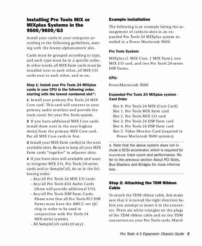
Example installation
The following is an example listing the ar-rangement of cards-to-slots in an ex-panded Pro Tools 24 MIXplus system in-stalled in a Power Macintosh 9600.
Pro Tools System:
MIXplus (1 MIX Core, 1 MIX Farm), one MIX I/O card, and two Pro Tools 24-series DSP Farms.
CPU:
PowerMacintosh 9600
Expanded Pro Tools 24 MIXplus system - Card Order
Slot 0. Pro Tools 24 MIX (Core Card)Slot 1. Pro Tools MIX Farm cardSlot 2. Pro Tools MIX I/O cardSlot 3. Pro Tools 24 DSP Farm cardSlot 4. Pro Tools 24 DSP Farm cardSlot 5. Video Monitor Card (required in
Power Macintosh 9600 systems)
✽ Note that the above system does not in-clude a SCSI accelerator, which is required for maximum track count and performance. Re-fer to the previous section About PCI Slots, Bus Masters and Bridges for more informa-tion.
Step 2: Attaching the TDM Ribbon Cable
To attach the TDM ribbon cable, first make sure that it is turned the right direction be-fore you attempt to insert it in the connec-tor. There are white triangles on the plugs of the TDM ribbon cable and on the TDM connectors on your Pro Tools cards. Match
Pro Tools 4.3 Expansion Chassis Guide 5
6
these triangles to make sure the TDM rib-bon cable is turned the right direction.
Starting with the first MIX Core, MIX I/O or d24 card, press the first node of the TDM cable into the receptacle at the top of the card until it snaps into place. Push down gently but firmly until the node is fully connected to the card. Try not to force this connection or you could damage the connector. When the plug is properly seated, the two tabs on the side of the rib-bon cable’s TDM connector will click shut. If you wish to detach the ribbon cable, squeeze the tabs on the TDM connector in-ward.
It is OK to have unused nodes at the end of the cable. Terminators are not required with the TDM cable.
Step 3: Connecting Additional Audio Interfaces
With Pro Tools 24 MIX systems, it is possi-ble to connect up to two 8-channel inter-faces to each Pro Tools 24 MIX card (Core or Farm) by purchasing Digidesign’s op-tional Y-cable adapter (contact your Digidesign dealer for information about this option). You can also connect one ad-ditional interface to each Farm card (up to a maximum of 72 channels of I/O). The primary interface must be connected to the first MIX Core card in your system. It will function as the clock master for the other interfaces in your system.
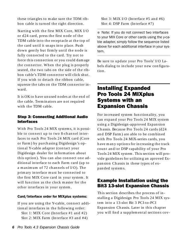
Card/Interface order for MIXplus systems:
If you are using the Y-cable, connect addi-tional interfaces in the following order:
Slot 1: MIX Core (Interface #1 and #2)Slot 2: MIX Farm (Interface #3 and #4)
Pro Tools 4.3 Expansion Chassis Guide
Slot 3: MIX I/O (Interface #5 and #6)Slot 4: DSP Farm (Interface #7)
✽ Note: If you do not connect two interfaces to your MIX Core or other cards using the y-ca-ble adapter, simply follow the sequence listed above for each additional interface in your sys-tem.
Be sure to update your Pro Tools’ I/O La-bels dialog to include your new configura-tion.
Installing Expanded Pro Tools 24 MIXplus Systems with an Expansion ChassisFor increased system functionality, you can expand your Pro Tools 24 MIX system using a Digidesign-approved Expansion Chassis. Because Pro Tools 24 cards (d24 and DSP Farm) are able to be combined with Pro Tools 24 MIX-series cards, you have many options for increasing the track count and/or DSP capability of your Pro Tools 24 MIX system. This section will pro-vide guidelines for utilizing an aproved Ex-pansion Chassis in these types of ex-panded systems.
Example Installation using the Bit3 13-slot Expansion ChassisThis section describes the process of in-stalling a Digidesign Pro Tools 24 MIX sys-tem into a 13-slot Bit 3 PCI-to-PCI Expansion Chassis. Later in this chapter you will find a supplemental sections cov-

ering the Bit 3 7-Slot and Magma 7- and 13-slot chasses.
Changing the Clock Skew to Improve Performance (Bit 3 13-slot Expansion Chassis only)
Before you install the host card in your computer, the clock skew may need to be changed. This is accomplished by chang-ing a jumper switch setting on the host card. Locate the set of jumper pins marked “J2” on the host card. If the jumper cap spans pins 2-3, it should be moved to span pins 1-2. This change ensures maximum track count with expanded Pro Tools 24 systems.
Before you begin
Please note the following before beginning your installation:
• Shut down your computer. • After your computer has completely
shut down, power down the Bit3 Expansion Chassis. both the computer and the chassis must be powered down during the entire installation process.
• Do not remove cards from their antistatic bags until you have discharged static electricity by touching a grounded object. Static electricity can damage integrated circuit cards. The power supply of your computer is a good grounding location.
• Be sure to have the Expansion Chassis cable connected to both the Expansion Chassis and the computer before powering up. If the cable becomes disconnected from the computer while the system is powered
on, shut down power to both the Expansion Chassis and the computer before reconnecting.
• When powering up, turn on the Expansion Chassis before the computer, and turn it off before powering down the computer. It is important that you do not leave the Chassis powered on when the computer has been powered off.
Your setup of the Bit 3 Expansion Chassis covers the following steps:
1. Installing the host card for the Expansion Chassis into the computer, and connecting the expansion chassis cable to the host card.
2. Installing the Bit 3 Backplane Controller card into the Expansion Chassis and connecting the other end of the expansion chassis cable to the Backplane Controller card.
3. Installing your Digidesign cards into the Expansion Chassis.
4. Connecting the Digidesign cards together via the Digidesign 8-node or 10-node TDM cable.
5. Connecting Digidesign Interfaces to the cards in the Expansion Chassis.
Step 1: Installing the Host CardInstall the Bit 3 host card into your com-puter and install the expansion unit cable into the host card. (Refer to the Bit 3 Ex-pansion Chassis manual for specific in-structions on these procedures.)
✽ NOTE: The 2- or 4-foot Expansion Chassis cable length may be used with Pro Tools 24 MIX systems. Use of the 6-foot cable is not supported.
Pro Tools 4.3 Expansion Chassis Guide 7
8
Card order in your computer
You should place the host card in the low-est numbered slot (Slot 0) in the computer. If you are unable to locate the lowest num-bered slot, consult the documentation that came with your CPU.
Step 2: Installing the Bit 3 Backplane Controller Card into the Expansion ChassisInstall the Bit 3 Backplane Controller card into the 13-slot Expansion Chassis. (Refer to your Bit 3 Expansion Chassis manual for specific instructions.)
Step 3: Installing Digidesign Cards into the ChassisCard order depends on which system you are using. Follow the examples below to determine the correct card order for your system.
When installing cards in the Bit 3 13-slot Expansion Chassis, make sure to observe the following:
1 The Controller Card must be in slot0
2 Slot 1 should be empty when using a Power Macintosh 9600, in which case the MIX Core card should be installed in Slot 4
3 With Power Macintosh 9500 and G3 computers, the Pro Tools MIX Core card (clock master card, primary audio inter-faces) should be installed in Slot1.
All other cards should follow sequentially, grouped according to type as described ear-lier:
1 all Mix Core cards together, then
2 all MIX Farm cards, then
Pro Tools 4.3 Expansion Chassis Guide
3 all d24 cards (if any), then
4 all MIX I/O cards, then
5 all Pro Tools 24 DSP Farms, then
6 all SampleCells.
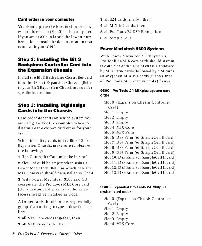
Power Macintosh 9600 Systems
With Power Macintosh 9600 systems, Pro Tools 24 MIX core cards should start in the 4th slot of the 13-slot chassis, followed by MIX Farm cards, followed by d24 cards (if any) then MIX I/O cards (if any), then all Pro Tools 24 DSP Farm cards (if any).
9600 - Pro Tools 24 MIXplus system card order
Slot 0: (Expansion Chassis Controller Card)
Slot 1: EmptySlot 2: EmptySlot 3: EmptySlot 4: MIX Core Slot 5: MIX FarmSlot 6: DSP Farm (or SampleCell II card)Slot 7: DSP Farm (or SampleCell II card)Slot 8: DSP Farm (or SampleCell II card)Slot 9: DSP Farm (or SampleCell II card)Slot 10: DSP Farm (or SampleCell II card)Slot 11: DSP Farm (or SampleCell II card)Slot 12: DSP Farm (or SampleCell II card)Slot 13: DSP Farm (or SampleCell II card)
9600 - Expanded Pro Tools 24 MIXplus system card order
Slot 0: (Expansion Chassis Controller Card)
Slot 1: EmptySlot 2: EmptySlot 3: EmptySlot 4: MIX Core
Slot 5: MIX Farm cardSlot 6: MIX Farm cardSlot 7: MIX Farm cardSlot 8: d24 cardSlot 9: MIX I/O cardSlot 10: DSP Farm or SampleCell II cardSlot 11: DSP Farm or SampleCell II cardSlot 12: DSP Farm or SampleCell II cardSlot 13: DSP Farm or SampleCell II card
Power Macintosh G3 Systems
With G3 systems, Pro Tools MIX Core cards should start in the 2nd slot of the 13-slot chassis, followed by other MIX cards (I/O and Farms) then Pro Tools 24-se-ries d24 and DSP Farm cards, then Sample-Cell II cards.
G3 - Single MIX Core system card order
Slot 0: (Expansion Chassis Controller Card)
Slot 1: EmptySlot 2: MIX CoreSlot 3: MIX Farm card Slot 4: d24 cardSlot 5: DSP Farm cardSlot 6: DSP Farm or SampleCell II cardSlot 7: DSP Farm or SampleCell II cardSlot 8: DSP Farm or SampleCell II cardSlot 9: DSP Farm or SampleCell II cardSlot 10: DSP Farm or SampleCell II cardSlot 11: DSP Farm or SampleCell II cardSlot 12: Available for other non-bus
master card
Step 4. Installing the TDM Ribbon CableTo attach the TDM cable, first make sure that it is turned the right direction before you attempt to insert it in the connectors.
There are white triangles on the plugs of the TDM ribbon cable and on the TDM connectors on your Pro Tools cards. Match these triangles to make sure the TDM rib-bon cable is turned the right direction.
Starting with the first card, press the first node of the TDM cable into the receptacle at the top of the card until it snaps into place. Push down gently but firmly until the node is fully connected to the card. Try not to force this connection or you could damage the connector. When the plug is properly seated, the two tabs on the side of the ribbon cable’s TDM connector will click shut. If you wish to detach the ribbon cable, squeeze the tabs on the TDM con-nector inward.
Each consecutive node should be con-nected to its corresponding card. It is OK to have unused nodes at the end of the ca-ble. Terminators are not required with the PCI version of the TDM ribbon cable.
Step 5. Connecting Digidesign Interfaces to the cards in the Expansion ChassisWith Pro Tools 24 MIX and MIXplus sys-tems, it is possible to connect up to two 8-channel interfaces to each MIX card by purchasing Digidesign’s optional Y-cable adapter. You can also connect one addi-tional interface to each DSP Farm card, up to a maximum of 72 channels of I/O. The primary interface must be connected to the first MIX Core card in your system. It will function as the clock master for the other interfaces in your system.
The order in which you connect your in-terfaces depends on which system you are
Pro Tools 4.3 Expansion Chassis Guide 9
10
using. Follow the instructions for your sys-tem below.
Power Macintosh 9600 Systems
9600 - Single MIX system interface order
Slot 0: (Expansion Chassis Controller Card)
Slot 1: EmptySlot 2: EmptySlot 3: EmptySlot 4: MIX Core (Interface #1 and #2)Slot 5: DSP Farm (Interface #3)Slot 6: DSP Farm (Interface #4)Slot 7: DSP Farm (Interface #5)Slot 8: DSP Farm (Interface #6)Slot 9: DSP Farm (Interface #7)Slot 10: DSP Farm (Interface #8)Slot 11: DSP Farm (Interface #9)Slot 12: availableSlot 13: available
▲ NOTE: If you choose not to connect two in-terfaces to the MIX Core card, simply follow the above sequence of DSP Farms for each additional interface.
9600 - Expanded Pro Tools 24 MIXplus system interface order
Slot 0: (Expansion Chassis Controller Card)
Slot 1: EmptySlot 2: EmptySlot 3: EmptySlot 4: MIX Core (Interface #1 and #2)Slot 5: MIX Farm (Interface #3 and 4)Slot 6: d24 (Interface #5 and 6)Slot 7: MIX I/O (Interface #7 and #8)Slot 8: DSP Farm (Interface #9)Slot 9: DSP Farm Slot 10: DSP Farm
Pro Tools 4.3 Expansion Chassis Guide
Slot 11: DSP Farm or SampleCell II cardSlot 12: DSP Farm or SampleCell II cardSlot 13: DSP Farm or SampleCell II card
▲ NOTE: If you choose not to connect two in-terfaces to each MIX card, simply follow the above sequence of DSP Farms for each addi-tional interface.
Power Macintosh G3 Systems
G3 - Single Pro Tools 24 MIX system interface order
Slot 0: (Expansion Chassis Controller Card)
Slot 1: EmptySlot 2: MIX Core (Interface #1 and #2)Slot 3: d24 (Interface #3 and #4)Slot 4: MIX I/O (Interface #5 and #6)Slot 5: DSP Farm (Interface #7)Slot 6: DSP Farm (Interface #8)Slot 7: DSP Farm (Interface #9)Slot 8: DSP Farm Slot 9: DSP Farm Slot 10: DSP FarmSlot 11: DSP Farm)Slot 12: availableSlot 13: available
▲ NOTE: If you choose not to connect two in-terfaces to a card using the Y-cable, simply follow the above sequence of DSP Farms for each additional interface.
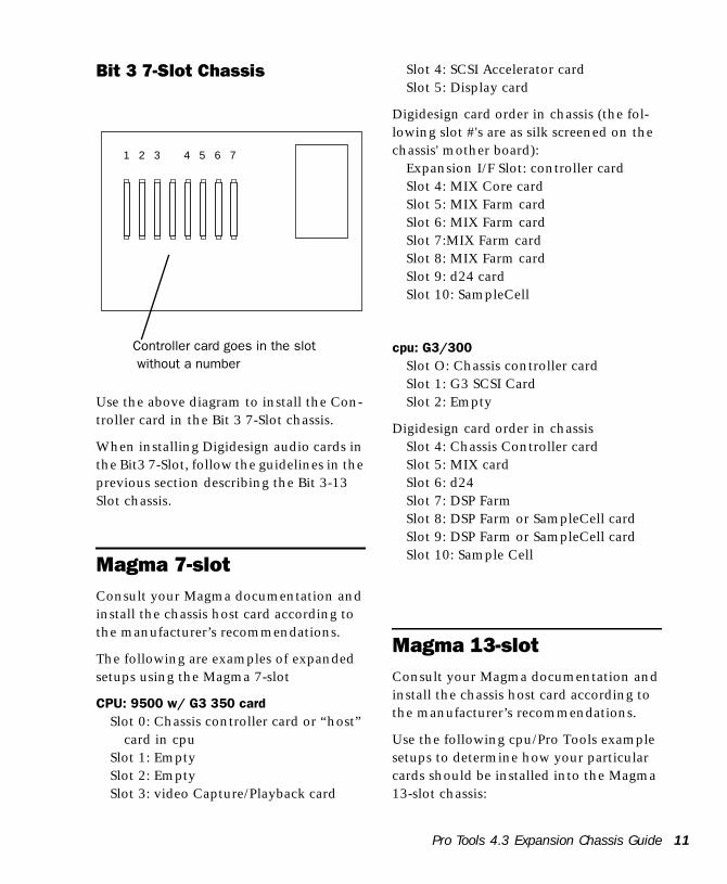
Bit 3 7-Slot Chassis
Use the above diagram to install the Con-troller card in the Bit 3 7-Slot chassis.
When installing Digidesign audio cards in the Bit3 7-Slot, follow the guidelines in the previous section describing the Bit 3-13 Slot chassis.
Magma 7-slotConsult your Magma documentation and install the chassis host card according to the manufacturer’s recommendations.
The following are examples of expanded setups using the Magma 7-slot
CPU: 9500 w/ G3 350 card Slot 0: Chassis controller card or “host”
card in cpuSlot 1: EmptySlot 2: EmptySlot 3: video Capture/Playback card
1 2 3 4 5 6 7
Controller card goes in the slot without a number
Slot 4: SCSI Accelerator card Slot 5: Display card
Digidesign card order in chassis (the fol-lowing slot #'s are as silk screened on the chassis' mother board):
Expansion I/F Slot: controller cardSlot 4: MIX Core cardSlot 5: MIX Farm cardSlot 6: MIX Farm cardSlot 7:MIX Farm cardSlot 8: MIX Farm cardSlot 9: d24 cardSlot 10: SampleCell
cpu: G3/300 Slot O: Chassis controller cardSlot 1: G3 SCSI CardSlot 2: Empty
Digidesign card order in chassisSlot 4: Chassis Controller cardSlot 5: MIX cardSlot 6: d24Slot 7: DSP FarmSlot 8: DSP Farm or SampleCell cardSlot 9: DSP Farm or SampleCell cardSlot 10: Sample Cell
Magma 13-slotConsult your Magma documentation and install the chassis host card according to the manufacturer’s recommendations.
Use the following cpu/Pro Tools example setups to determine how your particular cards should be installed into the Magma 13-slot chassis:
Pro Tools 4.3 Expansion Chassis Guide 11
12
CPU: G3/233 SCSI Accel card location: G3 slot C1Chassis: Magma 13 slotChassis host card location: G3 slot B1
Card order inside Magma Chassis (from left to right, beginning with the slot la-belled “P2”):
Slot 1: Chassis Controller cardSlot 2: MIX CoreSlot 3: MIXFarmSlot 4:MIX FarmSlot 5: d24Slot 6: DSP Farm or SampleCellSlot 7: DSP Farm or SampleCellSlot 8: DSP Farm or SampleCellSlot 9: DSP Farm or SampleCellSlot 10: DSP Farm or SampleCellSlot 11: DSP Farm or SampleCellSlot 12: Available for non-bus master
cardsSlot 13: Available for non-bus master
cards
Installing Expanded Pro Tools 24 SystemsThe compatibility and configuration infor-mation in this section applies to Pro Tools 24 systems only.
Card Order in Six-slot Computers
The PCI slots in your computer are grouped in banks of three, each controlled by a PCI Bridge Chip. A six-slot computer has two of these groups or bridges.
A bus master card is a PCI card that con-trols the data transfer to and from the
Pro Tools 4.3 Expansion Chassis Guide
bridge where it resides. Pro Tools d24 cards act as bus master cards.
Other cards that act as bus masters include:• Expansion Chassis host cards• SCSI accelerator cards• Most video capture cards(NOTE: this does not include video
monitor cards, which are not bus masters)
Consult the manufacturer of your third-party PCI cards to determine if they operate as bus masters.
✽ When setting up an expanded Pro Tools 24 system using a six-slot computer, you must take care to install your PCI cards in your com-puter so that your Pro Tools d24 card(s) are on a separate PCI bridge from other bus master cards.
When using an expansion chassis with a six-slot computer, you must place the chassis host card on a separate bridge from other bus master cards.
For more information on card installation order, see the instructions below for your system configuration.
Pro Tools 24 Expanded Systems without an Expansion ChassisWith Pro Tools 24, it is possible to install two d24 cards and two DSP Farms in cer-tain 6-slot computers. For maximum track count, a Digidesign-approved SCSI acceler-ator card is required with this configura-tion. (For the latest compatibility informa-tion, contact your Digidesign dealer or visit Digidesign’s website at www.digide-sign.com.)
Before you install the additional cards, note the following about card order. Cor-rect slot order is essential for maximum track count and optimum performance. To properly install your Digidesign cards you must begin installing them from the low-est numbered slot in your computer. In Power Macintosh 9600 models, the lowest numbered slot is the one that is located closest to the center of the computer (near-est the power supply).
If you are unable to locate the lowest num-bered slot, you can use the DigiTest Utility to locate it.
To Use DigiTest:
◆ Locate the DigiTest 2.6 application on your Pro Tools Installer disc. Double click the DigiTest application icon. When DigiT-est opens, a graphic representation of your computer will appear. This illustration will show the available PCI slots in your com-puter and their corresponding numbers.
Installing Cards in the Correct Slot Order
Install your cards in your computer in the following order, starting with the lowest alphanumeric slot:
Slot 0. Pro Tools d24 cardSlot 1. Pro Tools d24 cardSlot 2. Pro Tools PCI DSP FarmSlot 3. Pro Tools PCI DSP FarmSlot 4. Pro Tools PCI DSP FarmSlot 5. Video Monitor Card (required in
Power Mac 9600 systems)
Attaching the TDM Ribbon Cable
To attach the TDM ribbon cable, first make sure that it is turned the right direction be-
fore you attempt to insert it in the connec-tor. There are white triangles on the plugs of the TDM ribbon cable and on the TDM connectors on your d24 and DSP Farm cards. Match these triangles to make sure the TDM ribbon cable is turned the right direction.
Starting with the first d24 card, press the first node of the TDM cable into the recep-tacle at the top of the card until it snaps into place. Push down gently but firmly until the node is fully connected to the card. Try not to force this connection or you could damage the connector. When the plug is properly seated, the two tabs on the side of the ribbon cable’s TDM connec-tor will click shut. If you wish to detach the ribbon cable, squeeze the tabs on the TDM connector inward.
It is OK to have unused nodes at the end of the cable. Terminators are not required with the PCI version of the TDM cable.
Connecting Additional Audio Interfaces
With Pro Tools 24 systems, it is possible to connect up to two 8-channel interfaces to each d24 card by purchasing Digidesign’s optional Y-cable adapter. You can also con-nect one additional interface to each DSP Farm card, up to a maximum of 72 chan-nels of I/O. The primary interface must be connected to the first d24 card in your sys-tem. It will function as the clock master for the other interfaces in your system.
Connect additional interfaces in the fol-lowing order:
Slot 1: d24 (Interface #1 and #2)Slot 2: d24 (Interface #3 and #4)
Pro Tools 4.3 Expansion Chassis Guide 13
14
Slot 3: DSP Farm (Interface #5)Slot 4: DSP Farm (Interface #6)
✽ NOTE: If you do not connect two interfaces to each d24 card, simply follow the sequence of DSP Farms for each additional interface in your system.
Pro Tools 24 Expanded Systems with an Expansion ChassisFor increased system functionality, you can expand your Pro Tools 24 system using a Digidesign-approved Expansion Chassis.
Expansion Chassis Compatibility with Digidesign PCI Cards
The 7-slot and 13-slot Expansion Chassis from Bit 3 are functionally compatible with the following Digidesign PCI cards:
• Pro Tools d24 cards • Pro Tools PCI DSP Farms• SampleCell II PCI cards
The 7-slot Bit 3 Expansion Chassis can ac-commodate up to two d24 cards and five DSP Farms or SampleCell II cards. The 13-slot Bit 3 Expansion Chassis can accom-modate up to two d24 cards and eight DSP Farms or SampleCell II cards.
DAE and Digi System Init Requirements
With Pro Tools 24 systems, both the 7-slot and 13-slot Bit 3 Expansion Chassis require the use of Digidesign DAE and DSI 3.23 or higher.
Pro Tools 4.3 Expansion Chassis Guide
Bit 3 Expansion Chassis (7 slot)This section describes the process of in-stalling a Digidesign Pro Tools 24 system into a 7-slot Bit 3 PCI-to-PCI Expansion Chassis.
▲ If you are using a Power Macintosh G3 with a Bit 3 7-slot chassis, we suggest ordering a 10-node cable, which will make it easier to span unused slots.
Please note the following before begin-ning:
• Turn off your computer, then power down the chassis. Be sure that your computer and the Bit 3 Expansion Chassis are powered down during the entire installation process.
• Do not remove cards from their antistatic bags until you have discharged static electricity by touching a grounded object. Static electricity can damage integrated circuit cards. The power supply of your computer is a good grounding location.
• Be sure to have the Expansion Chassis cable connected to both the chassis and the computer before powering up. If the cable becomes disconnected from the computer while the system is powered on, shut down power to both the chassis and the computer before reconnecting.
• When powering up, turn on the Expansion Chassis before the computer, and turn it off before powering down the computer. It is important that you do not leave the Chassis powered on when the computer has been powered off.
Your setup of the Bit 3 Expansion Chassis covers the following steps:
1 Installing the host card for the Expan-sion Chassis into the computer, and con-necting the expansion chassis cable to the host card.
2 Installing the Bit 3 Backplane Controller card into the Expansion Chassis and con-necting the other end of the expansion chassis cable to the Backplane Controller card.
3 Installing your Digidesign cards into the Expansion Chassis.
4 Connecting the Digidesign cards to-gether via the Digidesign TDM ribbon ca-ble.
5 Connecting Digidesign Interfaces to the cards in the Expansion Chassis.
Step 1: Installing the Host CardInstall the Bit 3 host card into your com-puter and install the expansion unit cable into the host card. (Refer to the Bit 3 Ex-pansion Chassis manual for specific in-structions on these procedures.)
✽ NOTE: The 2- or 4-foot Expansion Chassis cable length may be used with Pro Tools 24 systems. Use of the 6-foot cable is not sup-ported.
Card order in your computer
You should place the host card in the low-est numbered slot (Slot 0) in the computer.
If you are unable to locate the lowest num-bered slot, you can use the DigiTest Utility version 2.6 to locate it.
To Use DigiTest:
◆ Locate the DigiTest 2.6 application on your Pro Tools Installer disc. Double click the DigiTest application icon. When DigiT-est opens, a graphic representation of your computer will appear. This illustration will show the available PCI slots in your com-puter and their corresponding numbers.
Step 2: Installing the Bit 3 Backplane Controller Card into the Expansion ChassisInstall the Bit 3 Backplane Controller card into the 7-slot Expansion Chassis. (Refer to your Bit 3 Expansion Chassis for specific instructions.)
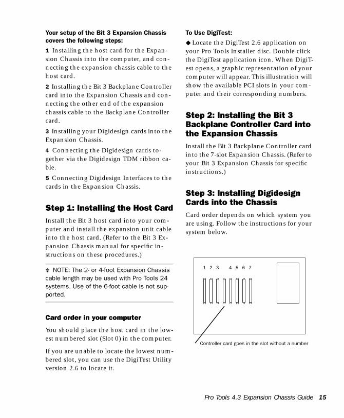
Step 3: Installing Digidesign Cards into the ChassisCard order depends on which system you are using. Follow the instructions for your system below.
1 2 3 4 5 6 7
Controller card goes in the slot without a number
Pro Tools 4.3 Expansion Chassis Guide 15
16
Power Macintosh 9600 Systems
With Power Macintosh 9600 systems, the Pro Tools d24 card should go in the low-est-numbered slots of the 7-slot chassis, followed by DSP Farm cards, then Sample-Cell II cards. The d24 card in Slot 1 is the master d24 card, so you should connect your first Audio Interface to it.
9600 - Single d24 system card order
Slot 1: d24 cardSlot 2: DSP FarmSlot 3: DSP Farm or SampleCell II cardSlot 4: DSP Farm or SampleCell II cardSlot 5: DSP Farm or SampleCell II cardSlot 6: DSP Farm or SampleCell II cardSlot 7: DSP Farm or SampleCell II card
Dual d24 configurations in the 7-slot Ex-pansion Chassis are not supported for Power Macintosh 9600 systems.
Power Macintosh G3 Systems
With G3 systems, the placement of the Pro Tools d24 card(s) is different. Begin at Slot 1 with your DSP Farm cards, followed by your SampleCell II cards (if any), and finish by installing your d24 card(s) in the highest-numbered slot(s) of the 7-slot chassis.
G3 - Single d24 system card order
Slot 1: DSP FarmSlot 2: DSP Farm or SampleCell II cardSlot 3: DSP Farm or SampleCell II cardSlot 4: DSP Farm or SampleCell II cardSlot 5: DSP Farm or SampleCell II cardSlot 6: DSP Farm or SampleCell II cardSlot 7: d24 card
Pro Tools 4.3 Expansion Chassis Guide
G3 - Dual d24 system card order
Slot 1: DSP FarmSlot 2: DSP FarmSlot 3: DSP Farm or SampleCell II cardSlot 4: DSP Farm or SampleCell II card Slot 5: DSP Farm or SampleCell II card Slot 6: d24 cardSlot 7: d24 card
If you do not use all the slots in your Ex-pansion Chassis, the cards should still be installed in the same manner, with the d24 card(s) in the highest-numbered slot(s), as in the following example:
G3 - Example system with five Digidesign cards
Slot 1: DSP FarmSlot 2: DSP FarmSlot 3: SampleCell II cardSlot 4: (unused)Slot 5: (unused)Slot 6: d24Slot 7: d24
Step 4. Installing the TDM Ribbon CableTo attach the TDM cable, first make sure that it is turned the right direction before you attempt to insert it in the connectors. There are white triangles on the plugs of the TDM ribbon cable and on the TDM connectors on your d24 and DSP Farm cards. Match these triangles to make sure the TDM ribbon cable is turned the right direction.
Starting with the first d24 card, press the first node of the TDM cable into the recep-tacle at the top of the card until it snaps into place. Push down gently but firmly until the node is fully connected to the card. Try not to force this connection or you could damage the connector. When the plug is properly seated, the two tabs on the side of the ribbon cable’s TDM connec-tor will click shut. If you wish to detach the ribbon cable, squeeze the tabs on the TDM connector inward.
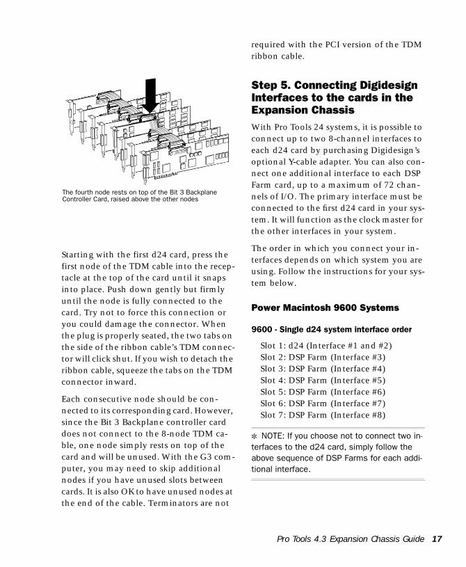
Each consecutive node should be con-nected to its corresponding card. However, since the Bit 3 Backplane controller card does not connect to the 8-node TDM ca-ble, one node simply rests on top of the card and will be unused. With the G3 com-puter, you may need to skip additional nodes if you have unused slots between cards. It is also OK to have unused nodes at the end of the cable. Terminators are not
The fourth node rests on top of the Bit 3 BackplaneController Card, raised above the other nodes
required with the PCI version of the TDM ribbon cable.
Step 5. Connecting Digidesign Interfaces to the cards in the Expansion ChassisWith Pro Tools 24 systems, it is possible to connect up to two 8-channel interfaces to each d24 card by purchasing Digidesign’s optional Y-cable adapter. You can also con-nect one additional interface to each DSP Farm card, up to a maximum of 72 chan-nels of I/O. The primary interface must be connected to the first d24 card in your sys-tem. It will function as the clock master for the other interfaces in your system.
The order in which you connect your in-terfaces depends on which system you are using. Follow the instructions for your sys-tem below.
Power Macintosh 9600 Systems
9600 - Single d24 system interface order
Slot 1: d24 (Interface #1 and #2)Slot 2: DSP Farm (Interface #3)Slot 3: DSP Farm (Interface #4)Slot 4: DSP Farm (Interface #5)Slot 5: DSP Farm (Interface #6)Slot 6: DSP Farm (Interface #7)Slot 7: DSP Farm (Interface #8)
✽ NOTE: If you choose not to connect two in-terfaces to the d24 card, simply follow the above sequence of DSP Farms for each addi-tional interface.
Pro Tools 4.3 Expansion Chassis Guide 17
18
Power Macintosh G3 Systems
With G3 systems, begin by connecting in-terfaces to the d24 card(s), then continue connecting interfaces by starting with the DSP farm in Slot 1 (farthest away from the d24).
G3 - Single d24 system interface order
Slot 1: DSP Farm (Interface #3)Slot 2: DSP Farm (Interface #4)Slot 3: DSP Farm (Interface #5)Slot 4: DSP Farm (Interface #6)Slot 5: DSP Farm (Interface #7)Slot 6: DSP Farm (Interface #8)Slot 7: d24 (Interface #1 and #2)
✽ NOTE: If you choose not to connect two in-terfaces to the d24 card, simply follow the above sequence of DSP Farms for each addi-tional interface.
With the Power Macintosh G3 computer, when you have two d24 cards in your Ex-pansion Chassis, the second highest d24 card becomes the master. In this case, you should connect your first Audio Interface to the second highest-numbered d24 card (Slot 6 in this example), as shown below.
G3 - Dual d24 system interface order
Slot 1: DSP Farm (Interface #5)Slot 2: DSP Farm (Interface #6)Slot 3: DSP Farm (Interface #7)Slot 4: DSP Farm (Interface #8)Slot 5: DSP Farm (Interface #9)Slot 6: d24 (Interface #1 and #2)Slot 7: d24 (Interface #3 and #4)
Pro Tools 4.3 Expansion Chassis Guide
✽ NOTE: If you choose not to connect two in-terfaces to each d24 card, simply follow the above sequence of DSP Farms for each addi-tional interface.
▲ If you do not use all the slots in your Expan-sion Chassis, you should still follow the same rule for connecting additional interfaces. Re-turning to our five-card example, you would connect interfaces in the following order:
G3 - Example system with five Digidesign cards
Slot 1: DSP Farm (Interface #5)Slot 2: DSP Farm (Interface #6)Slot 3: SampleCell II cardSlot 4: (unused)Slot 5: (unused)Slot 6: d24 (Interface #1 and #2)Slot 7: d24 (Interface #3 and #4)
Bit 3 Expansion Chassis (13 slot)This section describes the process of in-stalling a Digidesign Pro Tools 24 system into a 13-slot Bit 3 PCI-to-PCI Expansion Chassis.
Changing the Clock Skew to Improve Performance
(Bit 3 13-slot Expansion Chassis only)
Before you install the host card in your computer, the clock skew may need to be changed. This is accomplished by chang-ing a jumper switch setting on the host card. Locate the set of jumper pins marked
“J2” on the host card. If the jumper cap spans pins 2-3, it should be moved to span pins 1-2. This change ensures maximum track count with expanded Pro Tools 24 systems.
Before you begin
Please note the following before beginning your installation:
• Turn off your computer, then power down your chassis. Be sure that your computer and the Bit 3 Expansion Chassis are powered down during the entire installation process.
• Do not remove cards from their antistatic bags until you have discharged static electricity by touching a grounded object. Static electricity can damage integrated circuit cards. The power supply of your computer is a good grounding location.
• Be sure to have the Expansion Chassis cable connected to both the Expansion Chassis and the computer before powering up. If the cable becomes disconnected from the computer while the system is powered on, shut down power to both the Expansion Chassis and the computer before reconnecting.
• When powering up, turn on the Expansion Chassis before the computer, and turn it off before powering down the computer. It is important that you do not leave the Chassis powered on when the computer has been powered off.
Your setup of the Bit 3 Expansion Chassis covers the following steps:
1. Installing the host card for the Expansion Chassis into the computer, and connecting the expansion chassis cable to the host card.
2. Installing the Bit 3 Backplane Controller card into the Expansion Chassis and connecting the other end of the expansion chassis cable to the Backplane Controller card.
3. Installing your Digidesign cards into the Expansion Chassis.
4. Connecting the Digidesign cards together via the Digidesign 8-node or 10-node TDM cable.
5. Connecting Digidesign Interfaces to the cards in the Expansion Chassis.
Step 1: Installing the Host CardInstall the Bit 3 host card into your com-puter and install the expansion unit cable into the host card. (Refer to the Bit 3 Ex-pansion Chassis manual for specific in-structions on these procedures.)
✽ NOTE: The 2- or 4-foot Expansion Chassis cable length may be used with Pro Tools 24 systems. Use of the 6-foot cable is not sup-ported.
Card order in your computer
You should place the host card in the low-est numbered slot (Slot 0) in the computer. If you are unable to locate the lowest num-bered slot, you can use the DigiTest Utility version 2.6 to locate it.
To Use DigiTest:
◆ Locate the DigiTest v2.6 application on your Pro Tools Installer disc. Double click the DigiTest application icon. When DigiT-
Pro Tools 4.3 Expansion Chassis Guide 19
20
est opens, a graphic representation of your computer will appear. This illustration will show the available PCI slots in your com-puter and their corresponding numbers.
Step 2: Installing the Bit 3 Backplane Controller Card into the Expansion ChassisInstall the Bit 3 Backplane Controller card into the 13-slot Expansion Chassis. (Refer to your Bit 3 Expansion Chassis manual for specific instructions.)
Step 3: Installing Digidesign Cards into the ChassisCard order depends on which system you are using. Follow the instructions for your system below.
Power Macintosh 9600 Systems
With Power Macintosh 9600 systems, Pro Tools d24 cards should start in the 4th slot
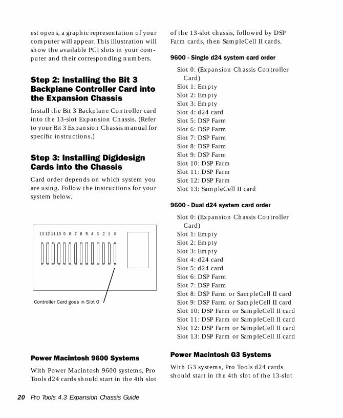
12345678910111213 0
Controller Card goes in Slot 0
Pro Tools 4.3 Expansion Chassis Guide
of the 13-slot chassis, followed by DSP Farm cards, then SampleCell II cards.
9600 - Single d24 system card order
Slot 0: (Expansion Chassis Controller Card)
Slot 1: EmptySlot 2: EmptySlot 3: EmptySlot 4: d24 cardSlot 5: DSP FarmSlot 6: DSP FarmSlot 7: DSP FarmSlot 8: DSP FarmSlot 9: DSP FarmSlot 10: DSP FarmSlot 11: DSP FarmSlot 12: DSP FarmSlot 13: SampleCell II card
9600 - Dual d24 system card order
Slot 0: (Expansion Chassis Controller Card)
Slot 1: EmptySlot 2: EmptySlot 3: EmptySlot 4: d24 cardSlot 5: d24 cardSlot 6: DSP FarmSlot 7: DSP FarmSlot 8: DSP Farm or SampleCell II cardSlot 9: DSP Farm or SampleCell II cardSlot 10: DSP Farm or SampleCell II cardSlot 11: DSP Farm or SampleCell II cardSlot 12: DSP Farm or SampleCell II cardSlot 13: DSP Farm or SampleCell II card
Power Macintosh G3 Systems
With G3 systems, Pro Tools d24 cards should start in the 4th slot of the 13-slot
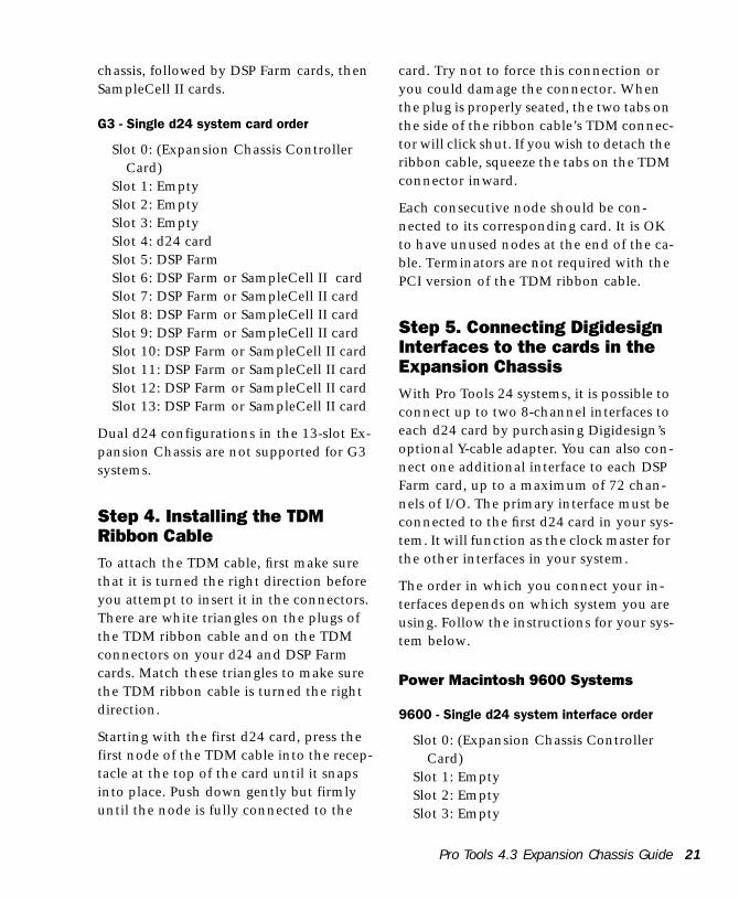
chassis, followed by DSP Farm cards, then SampleCell II cards.
G3 - Single d24 system card order
Slot 0: (Expansion Chassis Controller Card)
Slot 1: EmptySlot 2: EmptySlot 3: EmptySlot 4: d24 cardSlot 5: DSP FarmSlot 6: DSP Farm or SampleCell II cardSlot 7: DSP Farm or SampleCell II cardSlot 8: DSP Farm or SampleCell II cardSlot 9: DSP Farm or SampleCell II cardSlot 10: DSP Farm or SampleCell II cardSlot 11: DSP Farm or SampleCell II cardSlot 12: DSP Farm or SampleCell II cardSlot 13: DSP Farm or SampleCell II card
Dual d24 configurations in the 13-slot Ex-pansion Chassis are not supported for G3 systems.
Step 4. Installing the TDM Ribbon CableTo attach the TDM cable, first make sure that it is turned the right direction before you attempt to insert it in the connectors. There are white triangles on the plugs of the TDM ribbon cable and on the TDM connectors on your d24 and DSP Farm cards. Match these triangles to make sure the TDM ribbon cable is turned the right direction.
Starting with the first d24 card, press the first node of the TDM cable into the recep-tacle at the top of the card until it snaps into place. Push down gently but firmly until the node is fully connected to the
card. Try not to force this connection or you could damage the connector. When the plug is properly seated, the two tabs on the side of the ribbon cable’s TDM connec-tor will click shut. If you wish to detach the ribbon cable, squeeze the tabs on the TDM connector inward.
Each consecutive node should be con-nected to its corresponding card. It is OK to have unused nodes at the end of the ca-ble. Terminators are not required with the PCI version of the TDM ribbon cable.
Step 5. Connecting Digidesign Interfaces to the cards in the Expansion ChassisWith Pro Tools 24 systems, it is possible to connect up to two 8-channel interfaces to each d24 card by purchasing Digidesign’s optional Y-cable adapter. You can also con-nect one additional interface to each DSP Farm card, up to a maximum of 72 chan-nels of I/O. The primary interface must be connected to the first d24 card in your sys-tem. It will function as the clock master for the other interfaces in your system.
The order in which you connect your in-terfaces depends on which system you are using. Follow the instructions for your sys-tem below.
Power Macintosh 9600 Systems
9600 - Single d24 system interface order
Slot 0: (Expansion Chassis Controller Card)
Slot 1: EmptySlot 2: EmptySlot 3: Empty
Pro Tools 4.3 Expansion Chassis Guide 21
22
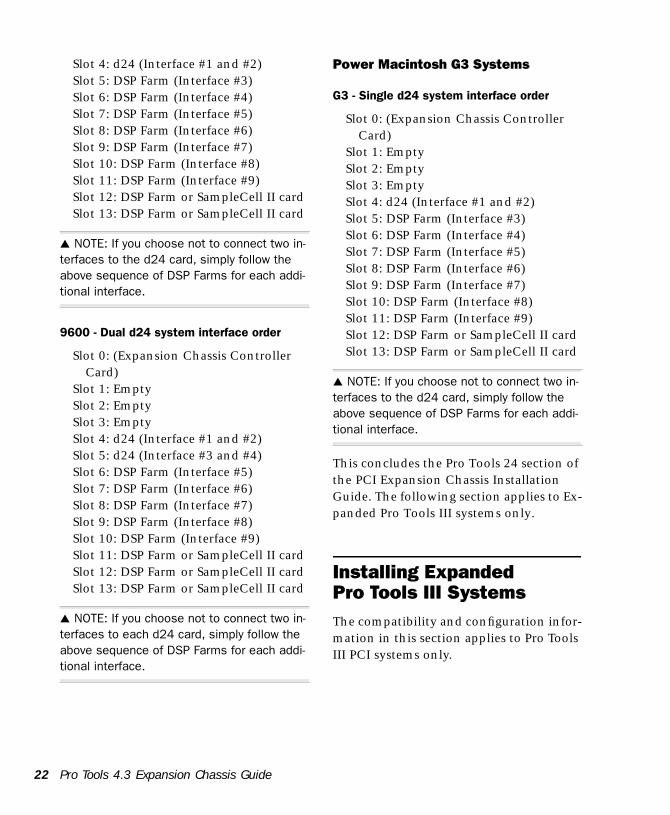
Slot 4: d24 (Interface #1 and #2)Slot 5: DSP Farm (Interface #3)Slot 6: DSP Farm (Interface #4)Slot 7: DSP Farm (Interface #5)Slot 8: DSP Farm (Interface #6)Slot 9: DSP Farm (Interface #7)Slot 10: DSP Farm (Interface #8)Slot 11: DSP Farm (Interface #9)Slot 12: DSP Farm or SampleCell II cardSlot 13: DSP Farm or SampleCell II card
▲ NOTE: If you choose not to connect two in-terfaces to the d24 card, simply follow the above sequence of DSP Farms for each addi-tional interface.
9600 - Dual d24 system interface order
Slot 0: (Expansion Chassis Controller Card)
Slot 1: EmptySlot 2: EmptySlot 3: EmptySlot 4: d24 (Interface #1 and #2)Slot 5: d24 (Interface #3 and #4)Slot 6: DSP Farm (Interface #5)Slot 7: DSP Farm (Interface #6)Slot 8: DSP Farm (Interface #7)Slot 9: DSP Farm (Interface #8)Slot 10: DSP Farm (Interface #9)Slot 11: DSP Farm or SampleCell II cardSlot 12: DSP Farm or SampleCell II cardSlot 13: DSP Farm or SampleCell II card
▲ NOTE: If you choose not to connect two in-terfaces to each d24 card, simply follow the above sequence of DSP Farms for each addi-tional interface.
Pro Tools 4.3 Expansion Chassis Guide
Power Macintosh G3 Systems
G3 - Single d24 system interface order
Slot 0: (Expansion Chassis Controller Card)
Slot 1: EmptySlot 2: EmptySlot 3: EmptySlot 4: d24 (Interface #1 and #2)Slot 5: DSP Farm (Interface #3)Slot 6: DSP Farm (Interface #4)Slot 7: DSP Farm (Interface #5)Slot 8: DSP Farm (Interface #6)Slot 9: DSP Farm (Interface #7)Slot 10: DSP Farm (Interface #8)Slot 11: DSP Farm (Interface #9)Slot 12: DSP Farm or SampleCell II cardSlot 13: DSP Farm or SampleCell II card
▲ NOTE: If you choose not to connect two in-terfaces to the d24 card, simply follow the above sequence of DSP Farms for each addi-tional interface.
This concludes the Pro Tools 24 section of the PCI Expansion Chassis Installation Guide. The following section applies to Ex-panded Pro Tools III systems only.
Installing Expanded Pro Tools III SystemsThe compatibility and configuration infor-mation in this section applies to Pro Tools III PCI systems only.
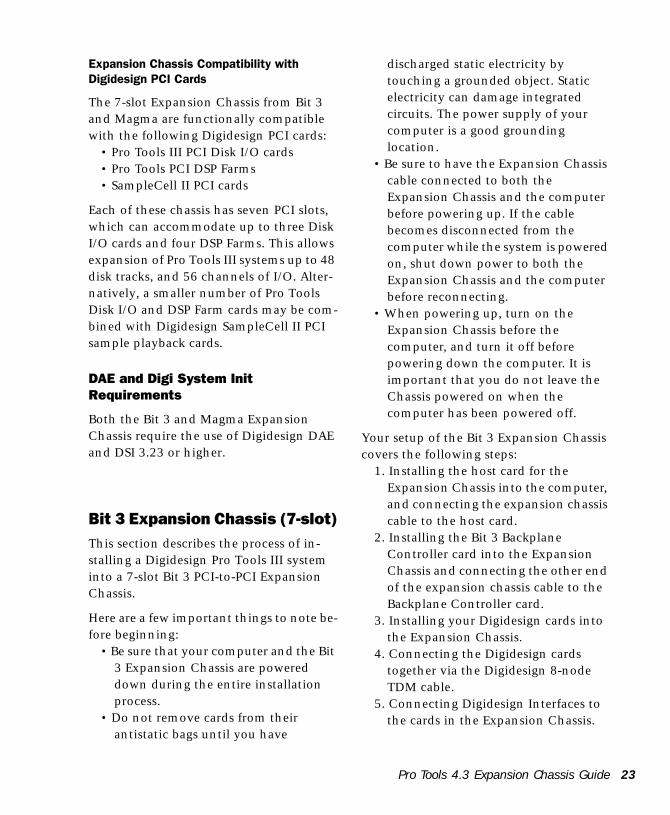
Expansion Chassis Compatibility with Digidesign PCI Cards
The 7-slot Expansion Chassis from Bit 3 and Magma are functionally compatible with the following Digidesign PCI cards:
• Pro Tools III PCI Disk I/O cards • Pro Tools PCI DSP Farms• SampleCell II PCI cards
Each of these chassis has seven PCI slots, which can accommodate up to three Disk I/O cards and four DSP Farms. This allows expansion of Pro Tools III systems up to 48 disk tracks, and 56 channels of I/O. Alter-natively, a smaller number of Pro Tools Disk I/O and DSP Farm cards may be com-bined with Digidesign SampleCell II PCI sample playback cards.
DAE and Digi System Init Requirements
Both the Bit 3 and Magma Expansion Chassis require the use of Digidesign DAE and DSI 3.23 or higher.
Bit 3 Expansion Chassis (7-slot)This section describes the process of in-stalling a Digidesign Pro Tools III system into a 7-slot Bit 3 PCI-to-PCI Expansion Chassis.
Here are a few important things to note be-fore beginning:
• Be sure that your computer and the Bit 3 Expansion Chassis are powered down during the entire installation process.
• Do not remove cards from their antistatic bags until you have
discharged static electricity by touching a grounded object. Static electricity can damage integrated circuits. The power supply of your computer is a good grounding location.
• Be sure to have the Expansion Chassis cable connected to both the Expansion Chassis and the computer before powering up. If the cable becomes disconnected from the computer while the system is powered on, shut down power to both the Expansion Chassis and the computer before reconnecting.
• When powering up, turn on the Expansion Chassis before the computer, and turn it off before powering down the computer. It is important that you do not leave the Chassis powered on when the computer has been powered off.
Your setup of the Bit 3 Expansion Chassis covers the following steps:
1. Installing the host card for the Expansion Chassis into the computer, and connecting the expansion chassis cable to the host card.
2. Installing the Bit 3 Backplane Controller card into the Expansion Chassis and connecting the other end of the expansion chassis cable to the Backplane Controller card.
3. Installing your Digidesign cards into the Expansion Chassis.
4. Connecting the Digidesign cards together via the Digidesign 8-node TDM cable.
5. Connecting Digidesign Interfaces to the cards in the Expansion Chassis.
Pro Tools 4.3 Expansion Chassis Guide 23
24
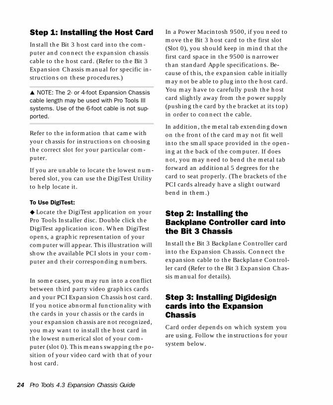
Step 1: Installing the Host CardInstall the Bit 3 host card into the com-puter and connect the expansion chassis cable to the host card. (Refer to the Bit 3 Expansion Chassis manual for specific in-structions on these procedures.)
▲ NOTE: The 2- or 4-foot Expansion Chassis cable length may be used with Pro Tools III systems. Use of the 6-foot cable is not sup-ported.
Refer to the information that came with your chassis for instructions on choosing the correct slot for your particular com-puter.
If you are unable to locate the lowest num-bered slot, you can use the DigiTest Utility to help locate it.
To Use DigiTest:
◆ Locate the DigiTest application on your Pro Tools Installer disc. Double click the DigiTest application icon. When DigiTest opens, a graphic representation of your computer will appear. This illustration will show the available PCI slots in your com-puter and their corresponding numbers.
In some cases, you may run into a conflict between third party video graphics cards and your PCI Expansion Chassis host card. If you notice abnormal functionality with the cards in your chassis or the cards in your expansion chassis are not recognized, you may want to install the host card in the lowest numerical slot of your com-puter (slot 0). This means swapping the po-sition of your video card with that of your host card.
Pro Tools 4.3 Expansion Chassis Guide
In a Power Macintosh 9500, if you need to move the Bit 3 host card to the first slot (Slot 0), you should keep in mind that the first card space in the 9500 is narrower than standard Apple specifications. Be-cause of this, the expansion cable initially may not be able to plug into the host card. You may have to carefully push the host card slightly away from the power supply (pushing the card by the bracket at its top) in order to connect the cable.
In addition, the metal tab extending down on the front of the card may not fit well into the small space provided in the open-ing at the back of the computer. If does not, you may need to bend the metal tab forward an additional 5 degrees for the card to seat properly. (The brackets of the PCI cards already have a slight outward bend in them.)
Step 2: Installing the Backplane Controller card into the Bit 3 ChassisInstall the Bit 3 Backplane Controller card into the Expansion Chassis. Connect the expansion cable to the Backplane Control-ler card (Refer to the Bit 3 Expansion Chas-sis manual for details).
Step 3: Installing Digidesign cards into the Expansion ChassisCard order depends on which system you are using. Follow the instructions for your system below.
Power Macintosh systems (except the G3)
With all supported Power Macintosh sys-tems except the G3, the Digidesign Disk I/O Card should go in the first slot of the Expansion Chassis. After the Disk I/O Card(s) are inserted, DSP Farm Cards should be inserted in consecutively num-bered slots, followed by SampleCell II cards, as shown below.
Power Macintosh Pro Tools III card order (except the G3)
Slot 1: Disk I/OSlot 2: Disk I/O or DSP FarmSlot 3: Disk I/O or DSP FarmSlot 4: DSP Farm or SampleCell II cardSlot 5: DSP Farm or SampleCell II cardSlot 6: DSP Farm or SampleCell II cardSlot 7: DSP Farm or SampleCell II card
Power Macintosh G3 Systems
With G3 systems, the placement of the disk I/O card(s) is different. Begin at Slot 1 with your DSP Farm cards, followed by your SampleCell II cards (if any), and fin-ish by installing your Disk I/Ocard(s) in the highest-numbered slot(s) of the 7-slot chassis.
G3 - Pro Tools III card order
Slot 1: DSP FarmSlot 2: DSP Farm or SampleCell II cardSlot 3: DSP Farm or SampleCell II cardSlot 4: DSP Farm or SampleCell II cardSlot 5: Disk I/O or DSP FarmSlot 6: Disk I/O or DSP FarmSlot 7: Disk I/O
☞ If you do not use all the slots in your Expan-sion Chassis, the cards should still be in-stalled in the same manner, with the Disk I/O card(s) in the higher-numbered slot(s), as in the following example:
G3 - Example system with five Digidesign cards
Slot 1: DSP FarmSlot 2: DSP FarmSlot 3: SampleCell II cardSlot 4: (unused)Slot 5: (unused)Slot 6: Disk I/OSlot 7: Disk I/O
Refer to your Pro Tools System Installation guide for full instructions on how to con-nect the SCSI Drive and Audio Interface ca-bles to the Disk I/O card(s)
▲ NOTE: Digidesign only supports the use of this chassis with Digidesign cards installed. Video capture cards should be installed di-rectly in the computer.
Step 4: Installing the TDM Ribbon CableTo attach the TDM cable, first make sure that it is turned the right direction before you attempt to insert it in the connectors. There are white triangles on the plugs of the TDM ribbon cable and on the TDM connectors on your Disk I/O and DSP Farm cards. Match these triangles to make sure the TDM ribbon cable is turned the right direction.
Starting with the first Disk I/O card, press the first node of the TDM cable into the re-
Pro Tools 4.3 Expansion Chassis Guide 25
26
ceptacle at the top of the card until it snaps into place. Each consecutive node should be connected to its corresponding card. However, since the Bit 3 Backplane con-troller card does not connect to the 8-node TDM cable, one node simply rests on top of the card and will be unused. With the G3 computer, you may need to skip addi-tional nodes if you have unused slots be-tween cards. It is also OK to have unused nodes at the end of the cable. Terminators are not required with the PCI version of the TDM ribbon cable.
Step 5. Connecting Digidesign Interfaces to the cards in the Expansion ChassisThe order in which you connect your in-terfaces depends on which system you are using. Follow the instructions for your sys-tem below.
Power Macintosh systems (except the G3)
With all supported Power Macintosh sys-tems except the G3, the first interface should be connected to the first Digidesign Disk I/O Card in the first slot of the Expan-sion Chassis. Additional interfaces should be connected to successive cards in consec-utively numbered slots.
Power Macintosh - Pro Tools III interface order
(except the G3)Slot 1: Disk I/O (Interface #1)Slot 2: Disk I/O or DSP Farm (Interface
#2)Slot 3: Disk I/O or DSP Farm (Interface
#3)
Pro Tools 4.3 Expansion Chassis Guide
Slot 4: DSP Farm (Interface #4)Slot 5: DSP Farm (Interface #5)Slot 6: DSP Farm (Interface #6)Slot 7: DSP Farm (Interface #7)
Power Macintosh G3 Systems
With Power Macintosh G3 systems, the first interface should be connected to the Disk I/O card in the lowest numbered slot. Additional interfaces should be connected to the remaining Disk I/O cards in ascend-ing slot number order, followed by the DSP Farm card in slot 1, followed by the re-maining DSP Farm cards in ascending or-der.
G3 - Pro Tools III interface order
Slot 1: DSP Farm (Interface #4)Slot 2: DSP Farm (Interface #5)Slot 3: DSP Farm (Interface #6)Slot 4: DSP Farm (Interface #7)Slot 5: Disk I/O (Interface #1)Slot 6: Disk I/O (Interface #2)Slot 7: Disk I/O (Interface #3)
Magma Expansion Chassis (7-slot)This section of the installation guide de-scribes the process of installing a Digide-sign Pro Tools III system into a 7-slot Magma PCI-to-PCI Expansion Chassis.
Here are a few important things to note be-fore beginning:
• Always disconnect the power to the Expansion Box when servicing or installing cards. Be sure that the Magma Expansion Chassis is powered
down during the entire installation process.
• Do not remove circuit cards from their antistatic bags until you have discharged yourself by touching a grounded object. Static electricity can damage integrated circuit cards. The power supply of your computer is a good point of reference as a grounding location.
• Be sure to have the Expansion Chassis cable connected to both the Expansion Chassis and the computer before powering up. If the cable becomes disconnected from the computer while the system is powered on, shut down power to both the Expansion Chassis and the computer before reconnecting.
• When powering up, turn on the Expansion Chassis before the computer, and turn it off before powering down the computer. It is important that you do not leave the Chassis powered on when the computer has been powered off.
Your setup of the Magma Expansion Chas-sis covers the following steps:
1. Installing the PCI host card for the Expansion Chassis into the computer, and connecting the expansion chassis cable to the host card.
2. Installing the Magma Expansion Interface card into the Expansion Chassis and connecting the other end of the Expansion Chassis cable to the Expansion Interface card.
3. Installing your Digidesign cards into the Expansion Chassis.
4. Connecting the Digidesign cards together via the Digidesign 8-node TDM cable.
5. Connecting Digidesign Interfaces to the cards in the Expansion Chassis.
Step 1: Installing the Host CardInstall the Magma host card into the com-puter and install the expansion unit cable into the host card. (Refer to the Magma PCI Expansion Chassis manual for specific instructions on these procedures.)
In some cases, you may run into a conflict between third party video graphics cards and your PCI Expansion Chassis host card. If you notice abnormal functionality with the cards in your chassis or the cards in your expansion chassis are not recognized, you may want to install the host card in the lowest numerical slot of your com-puter (slot 0). This means swapping the po-sition of your video card with that of your host card.
In a Power Macintosh 9500, if you need to move the Magma host card to the first slot (Slot 0), you should keep in mind that the first card space in the 9500 is narrower than standard Apple specifications. Be-cause of this, the expansion cable initially may not be able to plug into the host card. You may have to carefully push the host card slightly away from the power supply (pushing the card by the bracket at its top) in order to connect the cable.
In addition, the metal tab extending down on the front of the card may not fit well into the small space provided in the open-ing at the back of the computer. If does not, you may need to bend the metal tab
Pro Tools 4.3 Expansion Chassis Guide 27
28
forward an additional 5 degrees for the card to seat properly. (The brackets of the PCI cards already have a slight outward bend in them.)
Step 2: Installing the Expansion Chassis Interface card into the Magma ChassisNext, install the Magma Expansion Inter-face card into the Expansion Chassis. Note that the Magma Expansion Interface card must be placed in the lowest numbered slot in the Magma Chassis. Connect the expansion cable to the Expansion Inter-face card (Refer to the Magma PCI Expan-sion Chassis manual for details).
With the 13-slot Magma, the Expansion Interface card pin layout is obviously dif-ferent from PCI and cannot be confused with it (as is the case with both Magma/Bit3 7 slot chassis). It's interface card slot is on the far left of the chassis. Magma 13 slots are numbered “P2” to “P15”, where the slot closest to the inter-face card is slot “P3” (“P2” is for the inter-face card). On Magma 13, slot order is from left to right, for Bit3 13 and Magma 7-slot, slot order is right to left because their host cards reside in the rightmost slot.
Step 3: Installing Digidesign cards into the Expansion ChassisThe Digidesign Disk I/O Card should go in the second slot of the Expansion Chassis.
Refer to the Pro Tools System Installation guide for full instructions on how to con-
Pro Tools 4.3 Expansion Chassis Guide
nect the Disk I/O and Audio Interface ca-bles to the disk I/O card.
After the Disk I/O Card(s) are inserted, DSP Farm Cards should be inserted in consecu-tive slots, followed by SampleCell II cards.
▲ NOTE: Digidesign will only support the use of this chassis with Digidesign cards installed. Video capture cards should be installed di-rectly in the computer.
Step 4. Installing the TDM Ribbon CableTo attach the TDM cable, first make sure that it is turned the right direction before you attempt to insert it in the connectors. There are white triangles on the plugs of the TDM ribbon cable and on the TDM connectors on your Disk I/O and DSP Farm cards. Match these triangles to make sure the TDM ribbon cable is turned the right direction.
Starting with the first Disk I/O card, press the first node of the TDM cable into the re-ceptacle at the top of the card until it snaps into place. Each consecutive node should be connected to its corresponding card. It is OK to have unused nodes at the end of the cable. Since the Magma Expansion Chassis supports seven cards, the last node will always remain unused. Terminators are not required with the PCI version of the TDM ribbon cable.
Step 5. Connecting Digidesign Interfaces to the cards in the Expansion ChassisWith Pro Tools III systems, connect your first interface to the Disk I/O card, and connect any additional interfaces to each DSP Farm card in consecutively numbered slots. The primary interface must be con-nected to the first Disk I/O card in your system. It will function as the clock master for the other interfaces in your system.
Pro Tools 4.3 Expansion Chassis Guide 29

Related Documents