Pump PST2 400 OPERATOR’S MANUAL 0154624en 005 0708 0 1 5 4 6 2 4 E N

Welcome message from author
This document is posted to help you gain knowledge. Please leave a comment to let me know what you think about it! Share it to your friends and learn new things together.
Transcript

Pump
PST2 400
OPERATOR’S MANUAL
0154624en 005
0708
0 1 5 4 6 2 4 E N


PST2 400 Table of Contents
wc_bo0154624005enTOC.fm 3
1. Foreword 4
2. Safety Information 5
2.1 Operating and Electrical Safety ............................................................ 62.2 Information Labels ................................................................................ 6
3. Operation 7
3.1 Names of Parts ..................................................................................... 73.2 Prior to Operation ................................................................................. 83.3 Installation ............................................................................................ 83.4 Electrical Wiring .................................................................................. 113.5 Electrical Circuit Diagrams ................................................................. 133.6 Operation ............................................................................................ 143.7 Residue Plate ..................................................................................... 17
4. Maintenance 18
4.1 Periodic Maintenance Table ............................................................... 184.2 Maintenance and Inspection .............................................................. 194.3 Disassembly and Reassembly ........................................................... 214.4 Disassembly ....................................................................................... 224.5 Impeller Inspection ............................................................................. 234.6 Impeller Reassembly .......................................................................... 244.7 Troubleshooting .................................................................................. 25
5. Technical Data 26
5.1 Standard Specifications ...................................................................... 265.2 Operating Specifications (50 Hz) ........................................................ 275.3 Dimensions ......................................................................................... 27

Foreword
wc_tx000001gb electric.fm 4
1 Foreword
This manual provides information and procedures to safely operateand maintain this Wacker Neuson model. For your own safety andprotection from injury, carefully read, understand and observe thesafety instructions described in this manual.
Keep this manual or a copy of it with the machine. If you lose thismanual or need an additional copy, please contact Wacker NeusonCorporation. This machine is built with user safety in mind; however,it can present hazards if improperly operated and serviced. Followoperating instructions carefully! If you have questions about operatingor servicing this equipment, please contact Wacker NeusonCorporation.
The information contained in this manual was based on machines inproduction at the time of publication. Wacker Neuson Corporationreserves the right to change any portion of this information withoutnotice.
All rights, especially copying and distribution rights, are reserved.
Copyright 2008 by Wacker Neuson Corporation.
No part of this publication may be reproduced in any form or by anymeans, electronic or mechanical, including photocopying, withoutexpress written permission from Wacker Neuson Corporation.
Any type of reproduction or distribution not authorized by WackerNeuson Corporation represents an infringement of valid copyrightsand will be prosecuted. We expressly reserve the right to maketechnical modifications, even without due notice, which aim atimproving our machines or their safety standards.

PST2 400 Safety Information
2. Safety Information
This manual contains DANGER, WARNING, CAUTION, NOTICE andNOTE callouts which must be followed to reduce the possibility ofpersonal injury, damage to the equipment, or improper service.
This is the safety alert symbol. It is used to alert you to potentialpersonal injury hazards. Obey all safety messages that follow thissymbol to avoid possible injury or death.
DANGER indicates a hazardous situation which, if not avoided, willresult in death or serious injury.
WARNING indicates a hazardous situation which, if not avoided, couldresult in death or serious injury.
CAUTION indicates a hazardous situation which, if not avoided, couldresult in minor or moderate injury.
NOTICE: Used without the safety alert symbol, NOTICE indicates asituation which, if not avoided, could result in property damage.
Note: Contains additional information important to a procedure.
DANGER
WARNING
CAUTION
wc_si000039gb.fm 5

Safety Information PST2 400
2.1 Operating and Electrical Safety
To reduce risk of electric shock, connect only to a properly grounded,grounding-type receptacle.
Risk of electric shock—this pump has not been investigated for use inswimming pool areas.
An acceptable motor-control switch shall be provided at the time ofinstallation according to local codes and regulations.
To reduce risk of electric shock, follow instructions in this manual forproper installation.
CAUTION: This pump may automatically restart. Prior to working onthe pump or control panel, all supply circuits must be disconnected.
CAUTION: Risk of shock—do not remove cord and strain relief.
2.2 Information Labels
Label Meaning
A nameplate listing the model number, item num-ber, revision number, and serial number is attached to each unit. Please record the informa-tion found on this plate so it will be available should the nameplate become lost or damaged. When ordering parts or requesting service infor-mation, you will always be asked to specify the model number, item number, revision number, and serial number of the unit.
WARNING
MADE IN TAIWAN
Wacker Neuson CorporationMenomonee Falls, WI 53051 USA
wc_si000039gb.fm 6
PST2 400 Operation
3. Operation
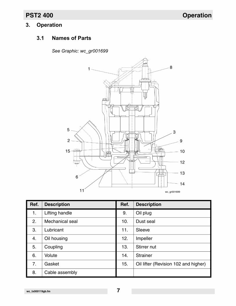
3.1 Names of Parts
See Graphic: wc_gr001699
Ref. Description Ref. Description
1. Lifting handle 9. Oil plug
2. Mechanical seal 10. Dust seal
3. Lubricant 11. Sleeve
4. Oil housing 12. Impeller
5. Coupling 13. Stirrer nut
6. Volute 14. Strainer
7. Gasket 15. Oil lifter (Revision 102 and higher)
8. Cable assembly
wc_gr001699
81
9
10
12
13
14
6
11
15
2
5 3
wc_tx000119gb.fm 7

Operation PST2 400
3.2 Prior to Operation
When the pump is delivered, first perform the following checks:• InspectionWhile unpacking, inspect the product for damage during shipment, andmake sure all bolts and nuts are tightened properly.• Specification checkCheck the model number to make sure it is the product that wasordered. Be certain it is the correct voltage and frequency.Note: If there is any problem with the product as shipped, contact yournearest dealer or Wacker Neuson representative at once.• Product specificationsDo not operate this product under any conditions other than those forwhich it is specified. Failure to observe this precaution can lead toelectrical shock, current leakage, fire, water leakage or otherproblems.
3.3 Installation
If the pump is used for outdoor fountains, garden ponds and similarplaces, or to drain a swimming pool, the pump must be supplied by anisolating transformer or connected to a Residual Current Device (RCD)with a residual operating current not exceeding 30 mA.The pump must not be used when people are in the water.Leakage of pump lubricants may cause pollution of water.Proper plug must be provided according to local codes and standards.Refer to wiring diagram. DO NOT use this pump in liquids other than water, such as oil, saltwater, or organic solvents.Use with a power supply voltage within ±5% of the rated voltage.DO NOT use in water temperatures outside the range of 0–40°C (32–104°F) which can lead to failure, electrical leakage or shock.DO NOT use in the vicinity of explosive or flammable materials.Use only in fully assembled state.Note: Consult your local dealer or Wacker Neuson representativebefore using with any liquids other than those indicated in this manual.
CAUTION
WARNING
wc_tx000119gb.fm 8
PST2 400 Operation
Preparing for installationBefore installing the pump at a work site, you will need to have thefollowing tools and instruments ready:• Insulation resistance tester (megohmmeter)• AC voltmeter• AC ammeter (clamp-on type)• Bolt and nut tighteners• Power supply connection tools (screwdriver or box wrench)Note: Please also read the instructions that come with each of the testinstruments.Checks to make before installation• When a grounded plug is used:Use the megohmmeter to measure the insulation resistance betweenthe cable assembly prongs and ground.• When connection leads are used:With the megohmmeter, measure the insulation resistance betweeneach core lead and the ground lead.Reference insulation resistance: 20MW or greater Note: The reference insulation resistance (20MW or greater) is thevalue when the pump is new or has been repaired. For the referencevalue after installation, see “Maintenance and Inspection.”Precautions During InstallationDo not under any circumstances install or move the pump bysuspending it from the cable assembly. The cable may be damaged,causing electrical leakage, shock, or fire. When installing the pump, pay close attention to its center of gravityand weight. If it is not lowered into place correctly, it may fall and bedamaged or cause injury.When transporting the pump by hand, be sure to employ manpowercommensurate with the weight of the pump. To avoid back injury whenlifting the pump, bend the knees to pick it up rather than bending yourback only.
3.3.1 This pump series is offered with a variety of discharge fittings. Followprocedures noted below to assure a proper discharge connection.Threaded Discharge Fitting (BSP) –Tighten hose coupling or discharge pipe securely and with propergaskets.
WARNING
CAUTION
wc_tx000119gb.fm 9

Operation PST2 400
Quick Disconnect Coupling (QD) –Assure coupling is tightened securely to pump discharge fitting andcompanion coupling is securely fastened with proper gaskets.Barbed Discharge Fitting (Barb) –Place hose clamp over hose and push hose to the base of thedischarge fitting. Tighten the hose clamp to secure the hose in place.3.3.2 Avoid dropping the pump or other strong impact. Lift the pump byholding it firmly with the hands or by attaching a rope or chain to thehandle.Note: On cable assembly handling, see Electrical Wiring.
3.3.3 Install the pump in a location with sufficient water level, where watercollects readily.Note: See “Operating Water Level” for the water level necessary foroperation. The discharge end of the hose should be located higherthan the water surface. If the end of the hose is submerged, water mayflow back to the pump when the pump is stopped; and if the hose endis lower than the water surface, water may overflow when the pump isturned off.
3.3.4 The hose should be run as straight as possible, since excessivebending will hinder the water flow, preventing sufficient lift, and caneven cause the hose to become clogged with earth. If the hose iscrimped near the pump, air can become trapped in the pump andcause idle running.
If large quantities of earth are sucked up, damage resulting fromfriction in the pump can lead to electrical leakage and shock.
3.3.5 Use the pump in the upright position. To prevent the pump frombecoming submerged in mud, mount it on a block or other firm base ifnecessary.
3.3.6 If used in a permanent installation, where the pump is not readilyaccessible after installation, please contact Wacker Neuson for aduplicate nameplate to be installed at the wellhead or on the controlbox so that it will be readily visible.
CAUTION
wc_tx000119gb.fm 10

PST2 400 Operation
3.4 Electrical Wiring
Performing electrical wiring Electrical wiring should be performed by a qualified person in accordwith all applicable regulations. Failure to observe this precaution notonly risks breaking the law but is extremely dangerous. Incorrect wiring can lead to current leakage, electrical shock or fire.ALWAYS make sure the pump is equipped with the specified overloadprotectors and fuses or breakers, so as to prevent electrical shock froma current leak or pump malfunction.Operate within the capacity of the power supply and wiring.
GroundingDO NOT use the pump without first grounding it properly. Failure toground it can lead to electrical shock from a current leak or pumpmalfunction. DO NOT attach the grounding wire to a gas pipe, water pipe, lightningarrester or telephone grounding wire. Improper grounding can result inelectrical shock.
Connecting the power supplyBefore connecting leads to the terminal strip, make certain the powersupply is turned off (circuit breaker, etc.), to avoid electrical shock,shorting, or unexpected starting of the pump, leading to injury.Before inserting the power supply plug, make certain the power supplyis turned off (circuit breaker, etc.), to avoid electrical shock, shorting,or unexpected starting of the pump, leading to injury.Do not use the pump with the cable assembly or plug connectedloosely, which can result in electric shock, shorting, or fire.Draw power from a dedicated power outlet rated at 15 A or above.Sharing the outlet with other equipment may cause overheating at thebranch outlet and could result in fire.NOTICE: Be sure to use a dedicated power supply with a groundleakage circuit breaker.
Grounded plug Connect only to receptacle of proper voltage and current ratingmatching that of the plug provided with the cable assembly.
WARNING
WARNING
CAUTION
WARNING
CAUTION
wc_tx000119gb.fm 11

Operation PST2 400
Without Plug Tighten the ends of the cable assembly securely against the terminalboard. If installation of a grounded plug is required, use only a properlyrated and approved CEE plug and secure the ends of the cableassembly securely to power and ground terminals in accordance withthe plug manufacturer’s instructions.See Graphic: wc_gr000309
Cable AssemblyIf it is necessary to extend the cable assembly, use a core size equalto or larger than the original. This is necessary not only to avoid aperformance drop, but to prevent cable overheating which can result infire, electrical leakage or electrical shock.If a cable with cut insulation or other damage is submerged in thewater, there is a danger of damage to the pump, electrical leakage,electrical shock, or fire.Be careful not to let the cable assembly be cut or become twisted. Thismay result in damage to the pump, electrical leakage, electrical shock,or fire.If it is necessary to submerge the connection wires of the cableassembly in water, first seal the wires completely in a moldedprotective sleeve, to prevent electrical leakage, electrical shock, or fire.DO NOT allow the cable assembly wires or power supply plug tobecome wet.Make sure the cable does not become excessively bent or twisted, anddoes not rub against a structure in a way that might damage it.If used in a deep-well installation, the cable assembly should besecured every twenty feet.
Br
L
L1 L2
G/Y
wc_gr000309
G
CAUTION
wc_tx000119gb.fm 12
PST2 400 Operation
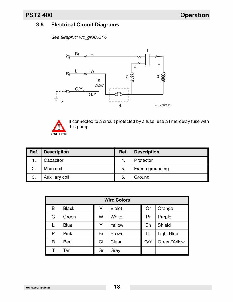
3.5 Electrical Circuit Diagrams
See Graphic: wc_gr000316
If connected to a circuit protected by a fuse, use a time-delay fuse withthis pump.
Ref. Description Ref. Description
1. Capacitor 4. Protector
2. Main coil 5. Frame grounding
3. Auxiliary coil 6. Ground
Wire Colors
B Black V Violet Or Orange
G Green W White Pr Purple
L Blue Y Yellow Sh Shield
P Pink Br Brown LL Light Blue
R Red Cl Clear G/Y Green/Yellow
T Tan Gr Gray
Br R1
L WB
L
325
46
G/YG/Y
wc_gr000316
CAUTION
wc_tx000119gb.fm 13

Operation PST2 400
3.6 Operation
Before starting3.6.1 Make sure once again that the product is of the correct voltage and
frequency rating.NOTICE: Using the product at other than rated voltage and frequencywill not only lower its performance but may damage the product.Note: Confirm the rated voltage and frequency on the modelnameplate.
3.6.2 Confirm the wiring, supply voltage, circuit breaker capacity, and motorinsulation resistance.Reference insulation resistance = 20 MW or greater.Note: The reference insulation resistance (20 MW or greater) is thevalue when the pump is new or has been repaired. For the referencevalue after installation see Maintenance and Inspection.
3.6.3 The setting on the circuit breaker or other overload protector should bemade in accord with the rated current of the pump.Note: See Operating Specifications for the rated current of the pump.
3.6.4 When powering the pump with a generator, be certain the generator issized to supply the required power for the pump and any otherequipment powered by the generator.
Test OperationNEVER operate the pump while it is suspended in the air. The recoilmay result in injury or other major accident.
NEVER start the pump when people are standing next to it. A currentleak can result in electrical shock.
Run the pump for a short time (3–10 minutes) and confirm thefollowing:• Using an ammeter (clamp-on type), measure the operating
current at the L1 and L2 phase wires on the terminal.COUNTERMEASURE: If the operating current exceeds the ratedvalue, pump motor overload may be a cause. Make sure the pump hasbeen installed under proper conditions as described in Installation.• Using an AC voltmeter (tester), measure voltage at the terminals.
Supply voltage tolerance: within ±5% of rated voltage.
WARNING
WARNING
wc_tx000119gb.fm 14

PST2 400 Operation
COUNTERMEASURE: If the supply voltage is outside the tolerance,possible causes are the power supply capacity or an inadequateextension cable. Look again at the wiring diagram and make sure theconditions are proper. In case of very excessive vibration, unusual noise or odor, turn off thepower immediately and consult your nearest dealer or Wacker Neusonrepresentative. Continuing to operate the pump under abnormalconditions may result in electrical shock, fire, or current leakage.OperationThe pump may become very hot during operation. Be careful not tocontact the pump accidentally to avoid being burned.Make sure no extraneous objects such as pins, nails or other metalobjects are sucked into the pump. These can damage the pump orcause it to malfunction, and can result in electrical shock or electricalleakage.When the pump is not used for an extended period, be sure to turn offthe power (circuit breaker, etc.). Deterioration of the insulation maylead to electrical leakage, electrical shock, or fire.In case of a power outage, turn off the power to the pump to avoidhaving it start unexpectedly when the power is restored, presentingserious danger to people in the vicinity.
The pump may become hot during operation. Do not touch anoperating pump. Allow the pump to cool before handling.Pay careful attention to the water level while the pump is operating. Dryoperation may cause the pump to malfunction.Note: See section Operating water level, for the water level necessaryfor operation.Sharp bends in the hose, especially near its base, may cause airpockets to form resulting in idle operation. Lessen the degree ofbending while continuing to operate the pump.
Operating water level Do not operate the pump below the C.W.L. (Continuous running WaterLevel) indicated below. Failure to observe this condition may result indamage to the pump, current leakage or electrical shock.
CAUTION
WARNING
CAUTION
CAUTION
wc_tx000119gb.fm 15

Operation PST2 400
See Graphic: wc_gr001222NPT 45-degree hose coupling is standard for the US market.
Motor Protection System (Motor Protector)The pump has a built-in motor protection system (Miniature Protector).If the motor overheats, for reasons such as the following, the pump willautomatically stop operating regardless of the water level, to protectthe motor:• Change in supply voltage polarity• Overload• Open-phase operation or operation under constraintNote: Always determine the cause of the problem and resolve it beforeresuming operation. Simply repeating cycles of stopping and restartingwill result in damage to the pump. Do not continue operation at verylow lift, low water level, or while the strainer is clogged with debris. Notonly will performance suffer, but also such conditions may causenoise, heavy vibration, and malfunctioning.
Pump Model Continuous running Water Level
PST2 400 w/strainer 90mm (3.5")
PST2 400 w/residue plate 10mm (0.4”)
wc_gr001222
C.W.L
wc_tx000119gb.fm 16

PST2 400 Operation
3.7 Residue Plate
The residue plate kit contains the residue plate, washers, and bolts.Reuse nuts from pump assembly.
3.7.1 Remove the strainer (3) by loosening the three nuts (1) and removingthe three bolts (2). Keep nuts for reuse.
3.7.2 Position washers (4) and attach the residue plate (5) with new bolts (6)included with kit.Note: Be certain to use washers to prevent motor shaft stirrer nut fromprotruding through residue plate.
See Graphic: wc_gr001144
1
2
3
4
5
6
wc_gr001144
wc_tx000119gb.fm 17
Maintenance PST2 400
4. Maintenance
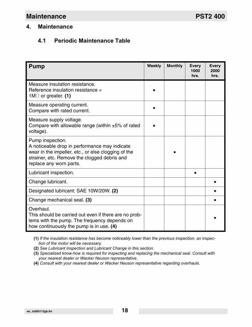
4.1 Periodic Maintenance Table
(1) If the insulation resistance has become noticeably lower than the previous inspection, an inspec-tion of the motor will be necessary.
(2) See Lubricant Inspection and Lubricant Change in this section.(3) Specialized know-how is required for inspecting and replacing the mechanical seal. Consult with
your nearest dealer or Wacker Neuson representative.(4) Consult with your nearest dealer or Wacker Neuson representative regarding overhauls.
Pump Weekly Monthly Every1000hrs.
Every2000hrs.
Measure insulation resistance.Reference insulation resistance =1MW or greater. (1)
Measure operating current.Compare with rated current.
Measure supply voltage.Compare with allowable range (within ±5% of rated voltage).
Pump inspection.A noticeable drop in performance may indicate wear in the impeller, etc., or else clogging of the strainer, etc. Remove the clogged debris and replace any worn parts.
Lubricant inspection.
Change lubricant.
Designated lubricant: SAE 10W/20W. (2)
Change mechanical seal. (3)
Overhaul.This should be carried out even if there are no prob-lems with the pump. The frequency depends on how continuously the pump is in use. (4)
wc_tx000112gb.fm 18

PST2 400 Maintenance
4.2 Maintenance and Inspection
Regular maintenance and inspections are a necessity for continuedefficient functioning of the pump. If any abnormal conditions arenoticed, refer to the Troubleshooting section and take correctivemeasures immediately. It is recommended that a spare pump be keptready in case of any problems.Prior to inspectingBefore inspecting the pump, make certain the power supply (circuitbreaker, etc.) is turned off. Then, unplug the cable assembly from thereceptacle or detach it from the terminals. Failure to follow thisprecaution may result in a serious accident from electrical shock orunexpected starting of the pump motor.
4.2.1 Washing the pumpRemove accumulated matter from the surface of the pump and washit with clean water. Take special care to remove any debris from theimpeller.
4.2.2 Inspecting the pump exteriorLook for any peeling or chipped paint, and make sure the nuts andbolts are fastened tightly. Any cracks in the surface should be repairedby cleaning that area, drying it and then applying a touch-up coating.Note: Touch-up paint is not supplied. Note that some kinds of damageor looseness may require that the unit be disassembled for repairs.Please consult your nearest dealer or Wacker Neuson representative.StorageWhen the pump is out of use for an extended period, wash it and dry itthoroughly, then store it indoors.Note: Always run a test operation before putting the pump back intoservice. If the pump is left in the water, it should be run a minimum of once aweek.
• Inspecting LubricantRemove the oil plug and tilt the pump to drain a small amount oflubricant. If the lubricant is milky white or has water mixed in with it, themechanical seal may be faulty. In this case the pump will need to bedisassembled and repaired.
• Replacing LubricantRemove the oil plug and drain all the lubricant, then replace it with thespecified amount.Note: Worn lubricant and other waste products should be disposed ofby a qualified agent, in accord with applicable laws. The oil plug gasketshould be replaced each time the lubricant is inspected or changed.
WARNING
wc_tx000112gb.fm 19

Maintenance PST2 400
See Graphic: wc_gr000245Replacement PartsThe table lists the parts that need to be replaced periodically. Replacethese using the recommended frequency as a guideline.
Ref. Description Ref. Description
1. Oil Inlet 3. Oil Plug
2. Gasket 4. Allen Wrench
Pump Model Lubricant Capacity
PST2 400 160 ml (5.4 fl. oz.)
PS 2 500, PSA 2 500 155 ml (5.2 fl. oz.)
PS 2 750 210 ml (7.1 fl. oz.)
Part Replacement Frequency
Mechanical seal When lubricant in oil compartment becomes milky.
Lubricant (SAE 10W/20W) Every 2,000 hours or 12 months, whichever comes first.
Gasket Each time pump is disassembled or inspected.
Dust seal When ring is worn, and each time pump is disassem-bled or inspected.
Sleeve When it becomes worn.
wc_tx000112gb.fm 20

PST2 400 Maintenance
4.3 Disassembly and Reassembly
Before disassembling the pump, make certain the power supply (circuitbreaker, etc.) is turned off. Then, unplug the cable assembly from thereceptacle or detach it from the terminals. To avoid electrical shock,DO NOT work with wet hands.NEVER check the operation of any parts (impeller rotation, etc.) byturning on the power while the unit is partially assembled. Failure toobserve these precautions may result in a serious accident.DO NOT disassemble or repair any parts other than those designatedhere. If repairs are necessary in any other than the designated parts,consult your nearest dealer or Wacker Neuson representative.Improper repairs can result in electrical leakage, electrical shock, fire,or water leaks.After reassembly, ALWAYS perform a test operation before resuminguse of the pump. Improper assembly will cause the pump tomalfunction, resulting in electric shock or water leaks.
The procedure for disassembly and reassembly is shown here to theextent necessary for impeller replacement. A specialized environmentand facilities are necessary for work on the mechanical seal and themotor parts. Contact your nearest dealer or Wacker Neusonrepresentative in the event such repairs are necessary.
WARNING
wc_tx000112gb.fm 21

Maintenance PST2 400
4.4 Disassembly
See Graphic: wc_gr000411
Note: For assembly or disassembly, place the pump on its side.Note: It is not necessary to drain the oil for disassembly and inspection of the impeller (w) or volute (aa). However, drain oil if furtherdisassembly and testing is required.
4.4.1 Remove three nuts (af) and the suction strainer (ac).4.4.2 Remove volute (aa) and volute gasket (ah).4.4.3 While keeping the impeller (w) from rotating, remove stirrer nut (z),
lockwasher (y) and washer (x). Impeller vanes may be very sharp due to excessive wear. Handle withcare.
4.4.4 Remove impeller (w).Note: If the parts are worn or damaged, make sure to replace themwith new ones.
CAUTION
wc_tx000112gb.fm 22

PST2 400 Maintenance
4.5 Impeller Inspection
See Graphic: wc_gr000411
4.5.1 Visually inspect impeller (w) for corrosion, wear or damage. Wornimpellers compromise peak performance.
4.5.2 Visually inspect impeller key and rotor shaft keyway for signs ofuneven wear.
4.5.3 Visually inspect volute (aa) casting for cracks, wear and damage. Lookfor signs of wear on volute cutwaters and surfaces facing impeller.
wc_tx000112gb.fm 23

Maintenance PST2 400
4.6 Impeller Reassembly
See Graphic: wc_gr000411Note: If, upon inspection and testing, a pump component requiresreplacement, use only original manufacturer’s replacement parts.
4.6.1 Turn pump on its side.4.6.2 Pre-assemble the dust seal (u) and sleeve (v). Slide the two pieces
(u & v) onto the rotor shaft. DO NOT apply oil to the surface where thedust seal (u) contacts the sleeve (v).
4.6.3 Align keyway of impeller (w) with keyway of rotor (not shown) and pushimpeller (w) onto rotor shaft.
4.6.4 Secure with washer (x), lockwasher (y) and stirrer nut (z).4.6.5 While holding the impeller from rotating, tighten stirrer nut (z).4.6.6 Position volute (aa) on suction strainer (ac), aligning with the three
bolts (ab) protruding from the suction strainer (ac).4.6.7 Replace gasket (ah) on top of volute (aa).4.6.8 Lift and hold remaining pump assembly in an upright position, align
three mounting flanges and lower into place.4.6.9 Assemble and secure three nuts (af).4.6.10 Tighten three nuts (af).4.6.11 Pre-test pump to verify proper operation.4.6.12 Performance test pump. Test results should be:
Maximum head > 10.06m (33ft)Maximum volume > 170.3 ltr/min (45gpm)
wc_tx000112gb.fm 24

PST2 400 Maintenance
4.7 Troubleshooting
Before ordering repairs, carefully read through this manual, thenrepeat the inspection. If the problem remains, contact your nearestdealer or Wacker Neuson representative.ALWAYS turn off the power before inspecting the pump. Failure toobserve this precaution can result in serious accident.
Problem / Symptom Reason / Remedy
Pump will not start • Power is off. Restore power.
• Cable assembly is cut or not connected properly. Repair/replace the cable or fix the connection.
• Impeller is clogged. Inspect the pump and remove any debris.
Pump stops soon after start-ing (Motor protector operates)
• Impeller is clogged. Remove debris.
• Low voltage. Provide the rated voltage, or make sure the cable assembly extension is the proper standard.
• Wrong power frequency. Check the nameplate, and replace the pump or the impeller.
• Extended operation with a clogged strainer. Remove debris from the strainer.
Poor lift or discharge capacity
• Faulty motor. Repair or replace the motor.
• Excessive sand is discharged. Place the pump on a block or other base to prevent the sand from being sucked into it.
• Worn out impeller. Replace.
• Sharply bent or clogged hose. Straighten out any sharp bends. Enclose the pump with a screen to keep away debris.
• Strainer clogged or buried. Remove debris from the strainer, or place a block under the pump.
Heavy vibration or noise • Damaged motor shaft. Contact dealer and replace motor.
WARNING
wc_tx000112gb.fm 25

Technical Data PST2 400
5. Technical Data
Machines discussed in this manual:
5.1 Standard Specifications
Machine PST2 400
BOM0009173, 0009174, 0009175, 00087850008786, 0008788, 0008789, 0620123
Applicable Liquids, Consistency and Temperature
Rain Water, Fountain Water, Ground Water, Sand-Carrying Water0–40°C (32–104°F)
Pump Impeller Semi-Vortex Type
Shaft Seal Double Mechanical Seal
Bearing Shielded Ball Bearing
Motor Specification Dry Submersible Induction Motor (2-Pole)
Insulation Class E
Protection System Miniature Protector
Lubricant SAE 10W/20W Such as:–Turbine Oil ISO VG #32–Shell Victrolia Oil #27–British Pet Energol THB #32–Gulf Paramount #32–Tellus #T22 Shell Oil–Shell Turbo T32
Connection Hose Coupling (Barb, BSP, QD–2")
wc_td000039gb.fm 26

PST2 400 Technical Data
5.2 Operating Specifications (50 Hz)
*The weight (mass) given above is the operating weight of the pump itself, not including the cable assembly.
5.3 Dimensions
PST2 400
0009175
0009173, 00091740008785, 00087860008788, 0008789
0620123
Pump
Electric Power V/Ph/Hz 110/1/50 230/1/50
Rated Current A 5.5 2.6
Starting Method Capacitor-Run
Discharge mm (in.) 50 (2)
Output kW (Hp) 0.40 (0.50)
Maximum Head m (ft.) 12 (39)
Maximum Capacity L/min(GPM)
200 (53)
Maximum Pressure kg/cm2
(psi)1.18 (16.8)
Solid Size Capacity mm (in.) 9.5 (0.4)
Weight* Kg (lbs.) 11.3 (25)
185(7.3)
250(9.8)
330(13.0)
wc_gr000610
PST2 400
mm (in.)
wc_td000039gb.fm 27


2008-CE-PST2-400_Q.fm
William Lahner Dan DomanskiVice President of Engineering Manager, Product Engineering
WACKER NEUSON CORPORATIONDate / Datum / Fecha / Date
EC DECLARATION OF CONFORMITYCE-KONFORMITÄTSERKLÄRUNG
DECLARACIÓN DE CONFORMIDAD DE LA CE DÉCLARATION DE CONFORMITÉ C.E.
WACKER NEUSON CORPORATION, N92 W15000 ANTHONY AVENUE, MENOMONEE FALLS, WISCONSIN USA
hereby certifies that the construction equipment specified hereunder: bescheinigt, daß das Baugerät: certifica que la máquina de:construcción / atteste que le matériel :
1. Category / Art / Categoría / Catégorie Water Pump Units
WasserpumpenEquipos de Bomba de AguaGroupe Motopompe à Eau
2. Type - Typ - Tipo - Type PST2 400
3. Item number of equipment / Artikelnummer / Número de referencia de la máquina / Numéro de référence du matériel :
0008788, 0008789, 0008785, 0008786, 0009173, 0009174, 0009175, 0620123
and has been produced in accordance with the following standards:und in Übereinstimmung mit folgenden Richtlinien hergestellt worden ist:y ha sido fabricado en conformidad con las siguientes normas:et a été produit conforme aux dispositions des directives européennes ci-après :
EN 60 335-2-41:96EN 60 335-1:94 + A11:95EMC 89/336/EECEN 50081-1:1992
AUTHORIZED REPRESENTATIVE IN THE EUROPEAN UNIONBEVOLLMÄCHTIGTER VERTRETER FÜR DIE EUROPÄISCHE GEMEINSCHAFTREPRESENTANTE AUTORIZADO EN LA UNIÓN EUROPEAREPRÉSENTANT AGRÉÉ AUPRÈS DE L’UNION EUROPÉENNE
WACKER CONSTRUCTION EQUIPMENT AGPreußenstraße 4180809 München
30.07.08

Wacker Construction Equipment AG · Preußenstraße 41 · D-80809 München · Tel.: +49-(0)89-3 54 02 - 0 · Fax: +49 - (0)89-3 54 02-3 90Wacker Neuson Corporation · P.O. Box 9007 · Menomonee Falls, WI 53052-9007 · Tel. : (262) 255-0500 · Fax: (262) 255-0550 · Tel. : (800) 770-0957Wacker Asia Pacific Operations · Skyline Tower, Suite 2303, 23/F · 39 Wang Kwong Road, Kowloon Bay, Hong Kong · Tel. +852 2406 60 32 · Fax: +852 2406 60 21
Related Documents