Lake Mead United States PLANETSCOPE PRODUCT SPECIFICATIONS PLANET.COM JUNE 2021

Welcome message from author
This document is posted to help you gain knowledge. Please leave a comment to let me know what you think about it! Share it to your friends and learn new things together.
Transcript

Lake MeadUnited States
PLANETSCOPEPRODUCT SPECIFICATIONS
PLANET.COM JUNE 2021

TABLE OF CONTENTS
1. OVERVIEW OF DOCUMENT 8
1.1. COMPANY OVERVIEW 8
1.2 DATA PRODUCT OVERVIEW 8
2. SATELLITE CONSTELLATION AND SENSOR OVERVIEW 9
2.1 PLANETSCOPE SATELLITE CONSTELLATION AND SENSOR CHARACTERISTICS 9
Table 2-A: PlanetScope Constellation and Sensor Specifications 10
3. PLANETSCOPE IMAGERY PRODUCTS 11
Table 3-A: PlanetScope Satellite Image Product Processing Levels 11
3.1 RADIOMETRIC INTERPRETATION 12
3.1.1 PLANETSCOPE HARMONIZATION 13
3.2 PLANETSCOPE BASIC ANALYTIC SCENE PRODUCT SPECIFICATION 14
Table 3-B: PlanetScope Analytic Basic Scene Product Attributes 14
3.3 PLANETSCOPE ORTHO PRODUCT SPECIFICATION 16
Table 3-C: PlanetScope Ortho Scene Product Attributes 16
3.3.1 PlanetScope Ortho Visual Scene Product Specification 17
Table 3-D: PlanetScope Visual Ortho Scene Product Attributes 17
3.3.2 PlanetScope Analytic Ortho Scene Product Specification 18
Table 3-E: PlanetScope Analytic Ortho Scene Product Attributes 18
3.4 RADIOMETRIC INTERPRETATION 19
4. PRODUCT PROCESSING 20
4.1 PLANETSCOPE PROCESSING 20
Table 4-A: PlanetScope Processing Steps 20
Figure 4: PlanetScope Image Processing Chain 21
5. PRODUCT METADATA 22
© Planet Labs Inc. 2021 2

5.1 ORTHO SCENES 22
Table 5-A: PlanetScope Ortho Scene GeoJSON Metadata Schema 22
Table 5-B: PlanetScope Ortho Scene Surface Reflectance GeoTIFF Metadata Schema 24
5.2 BASIC SCENES 26
Table 5-C: PlanetScope Basic Scene GeoJSON Metadata Schema 26
6. PRODUCT DELIVERY 28
6.1 PLANET APPLICATION PROGRAMMING INTERFACES (APIS) 28
6.2 PLANET EXPLORER GRAPHICAL USER INTERFACE (GUI) 28
6.3 PLANET ACCOUNT MANAGEMENT TOOLS 29
APPENDIX A – IMAGE SUPPORT DATA 30
1. GENERAL XML METADATA FILE 30
Table A-1: General XML Metadata File Field Descriptions 30
2. UNUSABLE DATA MASK FILE 35
3. USABLE DATA MASK FILE 36
No part of this document may be reproduced in any form or any means without the prior written consent of Planet.Unauthorized possession or use of this material or disclosure of the proprietary information without the prior written consentof Planet may result in legal action. If you are not the intended recipient of this report, you are hereby notified that the use,circulation, quoting, or reproducing of this report is strictly prohibited and may be unlawful.
© Planet Labs Inc. 2021 3

GLOSSARY
The following list defines terms used to describe Planet’s satellite imagery products.
Alpha MaskAn alpha mask is an image channel with binary values that can be used to render areas of the image producttransparent where no data is available.
Application Programming Interface (API)A set of routines, protocols, and tools for building software applications.
Atmospheric CorrectionThe process of correcting at-sensor radiance imagery to account for effects related to the interveningatmosphere between the earth’s surface and the satellite. Atmospheric correction has been shown tosignificantly improve the accuracy of image classification.
BlackfillNon-imaged pixels or pixels outside of the buffered area of interest that are set to black. They may appear aspixels with a value of “0” or as “noData” depending on the viewing software.
Digital Elevation Model (DEM)The representation of continuous elevation values over a topographic surface by a regular array of z-values,referenced to a common datum. DEMs are typically used to represent terrain relief.
GeoJSONA standard for encoding geospatial data using JSON (see JSON below).
GeoTIFFAn image format with geospatial metadata suitable for use in a GIS or other remote sensing software.
Ground Sample Distance (GSD)The distance between pixel centers, as measured on the ground. It is mathematically calculated based onoptical characteristics of the telescope, the altitude of the satellite, and the size and shape of the CCD sensor.
Graphical User Interface (GUI)Web based interfaces enable users to interact with Planet's imagery products without needing knowledge ofhow to use APIs or Application Programming Interfaces.
JavaScript Object Notation (JSON)Text-based data interchange format used by the Planet API.
Landsat 8Freely available dataset offered through NASA and the United States Geological Survey.
MetadataData delivered with Planet’s imagery products that describes the products content and context and can beused to conduct analysis or further processing.
© Planet Labs Inc. 2021 4

NadirThe point on the ground directly below the satellite.
Near-Infrared (NIR)Near Infrared is a region of the electromagnetic spectrum.
OrthorectificationThe process of removing and correcting geometric image distortions introduced by satellite collectiongeometry, pointing error, and terrain variability.
Ortho TileOrtho Tiles are Planet’s core product lines of high-resolution satellite images. Ortho tiles are available in twodifferent product formats: Visual and Analytic, each offered in GeoTIFF format.
PlanetScopeThe first three generations of Planet’s optical systems are referred to as PlanetScope 0, PlanetScope 1, andPlanetScope 2.
Radiometric CorrectionThe correction of variations in data that are not caused by the object or image being scanned. These includecorrection for relative radiometric response between detectors, filling non-responsive detectors and scannerinconsistencies.
Reflectance CoefficientThe reflectance coefficient provided in the metadata is used as a multiplicative to convert Analytic TOARadiance values to TOA Reflectance.
RapidEyeRapidEye refers to the five-satellite constellation operating between 2009 and 2020.
SceneA single image captured by a PlanetScope satellite.
Sensor CorrectionThe correction of variations in the data that are caused by sensor geometry, attitude and ephemeris.
Sentinel-2Copernicus Sentinel-2 is a multispectral imaging satellite constellation operated by the European SpaceAgency.
SkySatSkySat refers to the 15-satellite constellation in operation since 2014.
Sun AzimuthThe angle of the sun as seen by an observer located at the target point, as measured in a clockwise directionfrom the North.
© Planet Labs Inc. 2021 5

Sun ElevationThe angle of the sun above the horizon.
Sun Synchronous Orbit (SSO)A geocentric orbit that combines altitude and inclination in such a way that the satellite passes over any givenpoint of the planet’s surface at the same local solar time.
Surface Reflectance (SR)Surface reflectance is the amount of light reflected by the surface of the earth. It is a ratio of surface radiance tosurface irradiance, and as such is unitless, and typically has values between 0 and 1. The Surface Reflectance (SR)Product is derived from the standard Planet Analytic (Radiance) Product and is processed to top of atmospherereflectance and then atmospherically corrected to (bottom of atmosphere) surface reflectance. Planet uses the6S radiative transfer model with ancillary data from MODIS to account for atmospheric effects on the observedsignal at the sensor for the PlanetScope constellation.
Tile Grid SystemOrtho tiles are based on a worldwide, fixed UTM grid system. The grid is defined in 24 km by 24 km tile centers,with 1 km of overlap (each tile has an additional 500 m overlap with adjacent tiles), resulting in 25 km by 25 kmtiles.
Unusable Data Mask
The unusable data mask is a raster image having the same dimensions as the image product, indicating on apixel-by-pixel basis which pixels are unusable because they are cloud filled, outside of the observed area andtherefore blackfilled, or the pixel value is missing or suspect (due to saturation, blooming, hot pixels, dust,sensor damage, etc). The unusable data mask is an 8-bit image, where each pixel contains a bit patternindicating conditions applying to the imagery pixel. A value of zero indicates a "good" imagery pixel.
● Bit 0: Black fill - Identifies whether the area contains blackfill in all bands (this area was not imaged bythe spacecraft). A value of “1” indicates blackfill.
● Bit 1: Cloud - This pixel is assessed to likely be an opaque cloud.● Bit 2: Blue is missing or suspect.● Bit 3: Green is missing or suspect.● Bit 4: Red is missing or suspect.● Bit 5: Red Edge is missing or suspect (Rapideye only).● Bit 6: NIR is missing or suspect● Bit 7: Unused
Usable Data Mask
The usable data mask is a raster image having the same dimensions as the image product, comprised of 8bands, where each band represents a specific usability class mask. The usability masks are mutually exclusive,and a value of one indicates that the pixel is assigned to that usability class.
● Band 1: clear mask (a value of “1” indicates the pixel is clear, a value of “0” indicates that the pixel is notclear and is one of the 5 remaining classes below)
● Band 2: snow mask● Band 3: shadow mask● Band 4: light haze mask
© Planet Labs Inc. 2021 6

● Band 5: heavy haze mask● Band 6: cloud mask● Band 7: confidence map (a value of “0” indicates a low confidence in the assigned classification, a value
of “100” indicates a high confidence in the assigned classification)● Band 8: unusable data mask (see Unusable Data Mask above)
© Planet Labs Inc. 2021 7

1. OVERVIEW OF DOCUMENT
This document describes Planet satellite imagery products. It is intended for users of satellite imageryinterested in working with Planet’s product offerings.
1.1. COMPANY OVERVIEW
Planet uses an agile aerospace approach for the design of its satellites, mission control, and operations systems;and the development of its web-based platform for imagery processing and delivery.
1.2 DATA PRODUCT OVERVIEW
Planet operates the PlanetScope (PS) and SkySat (SS) Earth-imaging constellations. Imagery is collected andprocessed in a variety of formats to serve different use cases, be it mapping, deep learning, disaster response,precision agriculture, or simple temporal image analytics to create rich information products.
Planet offers two geometry types (Basic & Ortho) for PlanetScope imagery
The Basic Scene product is designed for users with advanced image processing and geometric correctioncapabilities. The product is not orthorectified or corrected for terrain distortions.
Ortho Scenes represent the single-frame image captures as acquired by a PlanetScope satellite with additionalpost processing applied.
Planet also offers two primary radiometry options for PlanetScope imagery
Visual products which are 3 band “RGB” which include color correction and sharpness enhancements toimprove image interpretation with the human eye
Analytic Products (4 or 8 band) with options for delivery as scaled Top of Atmosphere Radiance (TOAR) orSurface Reflectance (SR). Analytic products are recommended for quantitative & modeling applications.
PlanetScope imagery asset naming example
An “ortho_analytic_8b_sr” is an orthorectified, 8-band, surface reflectance PlanetScope Scene.A “basic_analytic_4b” is an unrectified, 4-band, top of atmosphere radiance PlanetScope Scene.An “ortho_visual” is an orthorectified, 3-band, color corrected, sharpened PlanetScope Scene.
© Planet Labs Inc. 2021 8

2. SATELLITE CONSTELLATION AND SENSOR OVERVIEW
2.1 PLANETSCOPE SATELLITE CONSTELLATION AND SENSOR CHARACTERISTICS
The PlanetScope satellite constellation consists of multiple launches of groups of individual satellites. Therefore,on-orbit capacity is constantly improving (in capability or quantity) as technology improvements are deployedat a rapid pace.
Each PlanetScope Dove satellite is a CubeSat ~3U form factor (10 cm by 10 cm by 30 cm). The completePlanetScope constellation of approximately 130 satellites is able to image the entire land surface of the Earthevery day (equating to a daily collection capacity of 200 million km²/day).
PlanetScope satellites launched starting in November 2018 have sensor characteristics that enable improvedspectral resolution. This second generation of PlanetScope satellites (known as Dove-R or PS2.SD) have a sensorplane divided into four separate horizontal stripes (one per radiometric band) along the track of the flight path.
A third generation of PlanetScope sensors (known as SuperDove or PSB.SD) is currently in orbit and isproducing imagery with 8 spectral bands.
Composite images from the second and third generation PlanetScope sensors are produced by an imageregistration process that involves compositing multiple frames ahead and behind an “anchor frame”. Band toband alignment is dependent on accurate ground-lock for the anchor frame and can vary according to scenecontent. For example, publication yield is observed to be lower in scenes over open water, mountainous terrain,or cloudy areas. Planet is always working to improve its publication rates and coverage and producing a highervolume of high quality imagery in challenging environments is an ongoing priority.
The band alignment quality threshold for image publication is based on across-track registration residuals, thepublication criteria are currently set to 0.4 pixels (BGRN) for “standard” PlanetScope products (instrumentsPS2.SD and PSB.SD), 0.66 (BGRN) to qualify for “test.”
© Planet Labs Inc. 2021 9

Table 2-A: PlanetScope Constellation and Sensor Specifications
CONSTELLATION OVERVIEW: PLANETSCOPE
Mission Characteristics Sun-synchronous Orbit
Instrument PS2 PS2.SD PSB.SD
Orbit Altitude (reference) 450 - 580 km (~98° inclination)
Max/Min LatitudeCoverage
±81.5° (dependent on season)
Equator Crossing Time 7:30 - 11:30 am (local solar time)
Sensor Type Four-band frame Imagerwith a split-frame VIS+NIRfilter
Four-band frame imagerwith butcher-block filterproviding blue, green, red,and NIR stripes
Eight-band frame imagerwith butcher-block filterproviding coastal blue,blue, green I, green II,yellow, red, red-edge, andNIR stripes
Spectral Bands Blue: 455 - 515 nmGreen: 500 - 590 nmRed: 590 - 670 nmNIR: 780 - 860 nm
Blue: 464 - 517 nmGreen: 547 - 585 nmRed: 650 - 682 nmNIR: 846 - 888 nm
Coastal Blue 431-452 nmBlue: 465-515 nmGreen I: 513. - 549 nmGreen II: 547. - 583 nmYellow: 600-620 nmRed: 650 - 680 nmRed-Edge: 697 - 713 nmNIR: 845 - 885 nm
Ground Sample Distance(nadir)
3.7 m-4.1 m (approximate, altitude dependent)
Frame Size 24 km x 8 km(approximate)
24 km x 16 km(approximate)
32.5 km x 19.6 km(approximate)
Maximum Image Strip perorbit
20,000 km²
Revisit Time Daily at nadir
Image Capture Capacity 200 million km²/day
Imagery Bit Depth 12-bit
© Planet Labs Inc. 2021 10
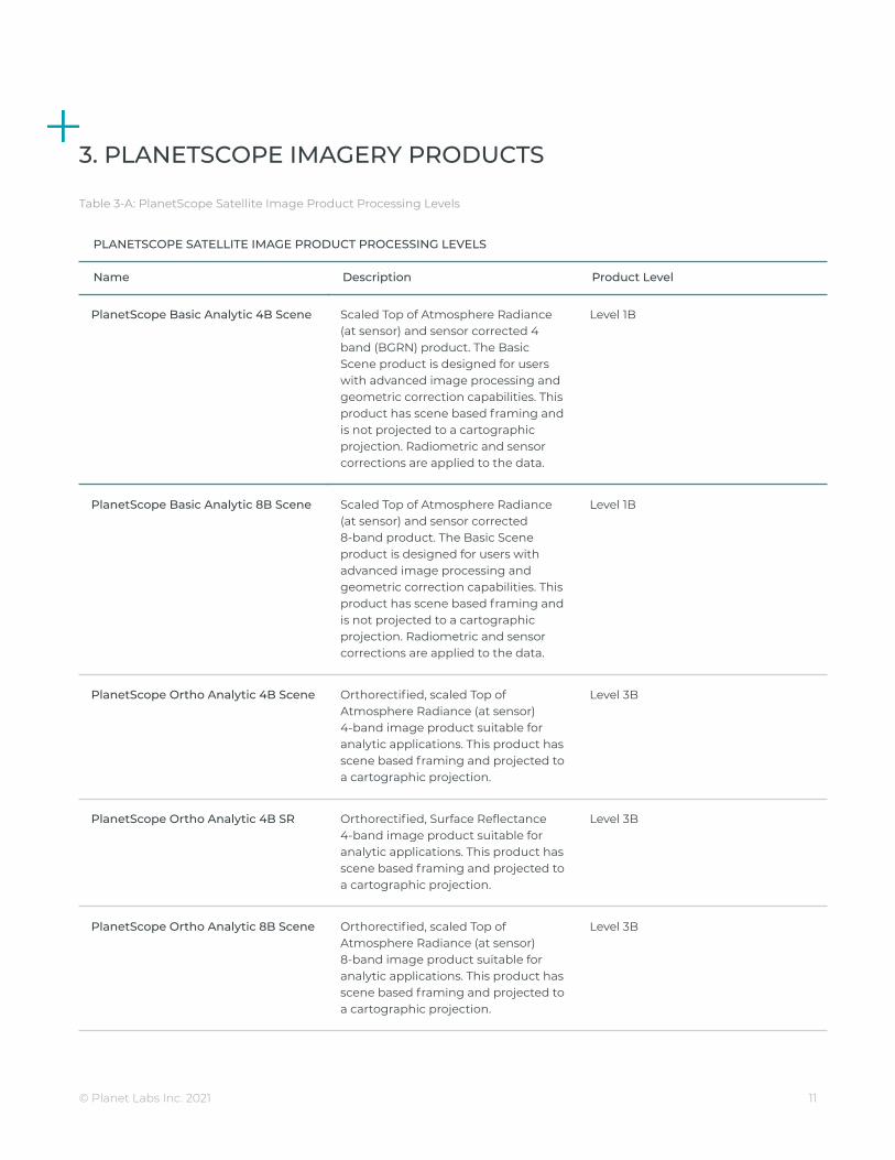
3. PLANETSCOPE IMAGERY PRODUCTS
Table 3-A: PlanetScope Satellite Image Product Processing Levels
PLANETSCOPE SATELLITE IMAGE PRODUCT PROCESSING LEVELS
Name Description Product Level
PlanetScope Basic Analytic 4B Scene Scaled Top of Atmosphere Radiance(at sensor) and sensor corrected 4band (BGRN) product. The BasicScene product is designed for userswith advanced image processing andgeometric correction capabilities. Thisproduct has scene based framing andis not projected to a cartographicprojection. Radiometric and sensorcorrections are applied to the data.
Level 1B
PlanetScope Basic Analytic 8B Scene Scaled Top of Atmosphere Radiance(at sensor) and sensor corrected8-band product. The Basic Sceneproduct is designed for users withadvanced image processing andgeometric correction capabilities. Thisproduct has scene based framing andis not projected to a cartographicprojection. Radiometric and sensorcorrections are applied to the data.
Level 1B
PlanetScope Ortho Analytic 4B Scene Orthorectified, scaled Top ofAtmosphere Radiance (at sensor)4-band image product suitable foranalytic applications. This product hasscene based framing and projected toa cartographic projection.
Level 3B
PlanetScope Ortho Analytic 4B SR Orthorectified, Surface Reflectance4-band image product suitable foranalytic applications. This product hasscene based framing and projected toa cartographic projection.
Level 3B
PlanetScope Ortho Analytic 8B Scene Orthorectified, scaled Top ofAtmosphere Radiance (at sensor)8-band image product suitable foranalytic applications. This product hasscene based framing and projected toa cartographic projection.
Level 3B
© Planet Labs Inc. 2021 11

PlanetScope Ortho Analytic 8B SR Orthorectified, scaled SurfaceReflectance 8-band image productsuitable for analytic applications. Thisproduct has scene based framing andprojected to a cartographic projection.
Level 3B
PlanetScope Ortho Visual Scene Orthorectified, scaled Top ofAtmosphere Radiance (at sensor) orSurface Reflectance 8-band imageproduct suitable for analyticapplications. This product has scenebased framing and projected to acartographic projection.
Level 3B
The name of each acquired PlanetScope image is designed to be unique and allow for easier recognition andsorting of the imagery. It includes the date and time of capture, as well as the id of the satellite that captured it.The name of each downloaded image product is composed of the following elements:
20210523_150823_65_242a_3B_AnalyticMS_SR_8b.tif20210523_150823_65_242a_3B_Visual.tif
<acquisition date>_<acquisition time>_<satellite_id>_<productLevel>_<bandProduct>.<extension>
3.1 RADIOMETRIC INTERPRETATION
Analytic products are scaled to Top of Atmosphere Radiance first. Validation of radiometric accuracy of theon-orbit calibration has been measured at 10% using collects over all the RadCalNet sites. Surface Reflectanceproducts are derived from TOAR precursors.
All PlanetScope satellite images are collected at a bit depth of 12 bits and stored on-board the satellites with abit depth of up to 12 bits. Radiometric corrections are applied during ground processing and all images arescaled to a 16-bit dynamic range. This scaling converts the (relative) pixel DNs coming directly from the sensorinto values directly related to absolute at-sensor radiances. The scaling factor is applied to minimizequantization error and the resultant single DN values correspond to 1/100th of a W/(m²*sr*μm). The DNs of thePlanetScope image pixels represent the absolute calibrated radiance values for the image.
Converting to Radiance and Top of Atmosphere Reflectance
To convert the pixel values of the Analytic products to radiance, it is necessary to multiply the DN value by theradiometric scale factor, as follows:
RAD(i) = DN(i) * radiometricScaleFactor(i), where radiometricScaleFactor(i) = 0.01
The resulting value is the at sensor radiance of that pixel in watts per steradian per square meter (W/m²*sr*μm).
© Planet Labs Inc. 2021 12

To convert the pixel values of the Analytic products to Top of Atmosphere Reflectance, it is necessary to multiplythe DN value by the reflectance coefficient found in the XML file. This makes the complete conversion from DNto Top of Atmosphere Reflectance to be as follows:
REF(i) = DN(i) * reflectanceCoefficient(i)
Atmospheric Correction
Surface reflectance is determined from top of atmosphere (TOA) reflectance, calculated using coefficientssupplied with the Planet Radiance product.
The Planet Surface Reflectance product corrects for the effects of the Earth's atmosphere, accounting for themolecular composition and variation with altitude along with aerosol content. Combining the use of standardatmospheric models with the use of NASA & ESA supplied water vapor, ozone and aerosol data, this providesreliable and consistent surface reflectance scenes over Planet's varied constellation of satellites as part of ournormal, on-demand data pipeline. However, there are some limitations to the corrections performed:
● In some instances there is no MODIS data overlapping a Planet scene or the area nearby. In those cases,AOD is set to a value of 0.226 which corresponds to a “clear sky” visibility of 23km, the aot_quality is setto the MODIS “no data” value of 127, and aot_status is set to ‘Missing Data - Using Default AOT’. If thereis no overlapping water vapor or ozone data, the correction falls back to a predefined 6SV internalmodel.
● The effects of haze and thin cirrus clouds are not corrected for.● Aerosol type is limited to a single, global model.● All scenes are assumed to be at sea level and the surfaces are assumed to exhibit Lambertian scattering
- no BRDF effects are accounted for.● Stray light and adjacency effects are not corrected for.
3.1.1 PLANETSCOPE HARMONIZATION
An xml file is included with PlanetScope image products, with coefficients to perform a rigorous approximatetransform of the Surface Reflectance measurements of the PS2 instrument PlanetScope satellites to theSurface Reflectance equivalents from PS2.SD and PSB.SD instrument PlanetScope satellites.
To convert the PS2 instrument PlanetScope Surface Reflectance values to a PSB.SD equivalent measurement,the harmonizationTransform parameters in the xml metadata should be used. This requires multiplying eachband by its associated bandCoefficient given in the xml metadata file, under bandSpecificMetadata.
Note, the harmonization process only applies to bands with a PS2 equivalent, specifically Blue, Green, Red, andNear-Infrared and only for Surface Reflectance values.
3.2 PLANETSCOPE BASIC ANALYTIC SCENE PRODUCT SPECIFICATION
The PlanetScope Basic Analytic product is a Scaled Top of Atmosphere Radiance (at sensor) and sensorcorrected product, providing imagery as seen from the spacecraft without correction for any geometric
© Planet Labs Inc. 2021 13

distortions inherent in the imaging process. It has a scene based framing, and is not mapped to a cartographicprojection. This product line is available in GeoTIFF and NITF 2.1 formats.
This product has not been processed to remove distortions caused by terrain and allows analysts to deriveinformation products for data science and analytics. It is designed for users with advanced image processingcapabilities and a desire to geometrically correct the product themselves. The imagery data is accompanied byRational Polynomial Coefficients (RPCs) to enable orthorectification by the user.
The geometric sensor corrections applied to this product correct for:
● Optical distortions caused by sensor optics● Co-registration of bands
The table below describes the attributes for the PlanetScope Basic Analytic Scene product:
Table 3-B: PlanetScope Analytic Basic Scene Product Attributes
PLANETSCOPE BASIC ANALYTIC SCENE PRODUCT ATTRIBUTES
Product Attribute Description
Product Components and Format The PlanetScope Basic Analytic product consists of the following file components:● Image File – GeoTIFF format● Metadata File – XML format● Rational Polynomial Coefficients (RPC) - XML format● Thumbnail File – GeoTIFF format● Unusable Data Mask (UDM) File – GeoTIFF format● Usable Data Mask (UDM2) File - GeoTIFF format
Information Content
Analytic Bands 4-band multispectral image (blue, green, red, near-infrared)8-band multispectral image (PSB.SD only)
Ground Sample Distance 3.7 m (average at reference altitude 475 km)
Processing
Pixel Size 3.7 - 4.1 m (altitude dependent GSD)
Bit Depth Analytic (DN): 12-bitAnalytic (Radiance - W m-2 sr-1 μm-1): 16-bit
Product Size Nominal scene size is approximately (at 475 km altitude):PS2: 24 km by 8 kmPS2.SD: 24 km by 16 kmPSB.SD: 32.5 km by 19.6 km
with some variability by satellite altitude.
Geometric Corrections Spacecraft-related effects are corrected using attitude telemetry and best availableephemeris data, and refined using GCPs.
Positional Accuracy Less than 10 m RMSE at 90th percentile
© Planet Labs Inc. 2021 14

Radiometric Corrections ● Conversion to absolute radiometric values based on calibration coefficients● Radiometric values scaled by 100 to reduce quantization error● Calibration coefficients are regularly monitored and updated with on-orbit
calibration techniques.
Map Projection N/A
3.3 PLANETSCOPE ORTHO PRODUCT SPECIFICATION
PlanetScope Ortho Scene products are orthorectified and are designed for a wide variety of applications thatrequire imagery with an accurate geolocation and cartographic projection. Ortho products have beenprocessed to remove distortions caused by terrain and can be used for cartographic purposes.
The Ortho Scenes are delivered as 3-band visual (RGB) and analytic (4 band & 8 band) products. Ortho Scenesare radiometrically-, sensor-, and geometrically-corrected (optional atmospherically corrected to SR) productsthat are projected to a cartographic map projection. The geometric correction uses fine Digital ElevationModels (DEMs) with a post spacing of between 30 and 90 meters.
Ground Control Points (GCPs) are used in the creation of every image and the accuracy of the product will varyfrom region to region based on available GCPs. Computer vision algorithms are used for extracting featurepoints such as OpenCV’s STAR keypoint detector and FREAK keypoint extractor. The GCP and tiepointmatching is done using a combination of RANSAC, phase correlation and mutual information.
The table below describes the attributes for the PlanetScope Ortho Scene product:
Table 3-C: PlanetScope Ortho Scene Product Attributes
GENERAL PLANETSCOPE ORTHO SCENE PRODUCT ATTRIBUTES
Product Attribute Description
Product Components and Format PlanetScope Ortho Scene product consists of the following file components:● Image File – GeoTIFF format● Metadata File – XML format● Thumbnail File – GeoTIFF format● Unusable Data Mask (UDM) file – GeoTIFF format● Usable Data Mask (UDM2) file - GeoTIFF format
Product Orientation Map North up
Product Framing Scene Based
Pixel Size (orthorectified) 3 m
Bit Depth Visual: 8-bit | Analytic (DN): 12-bitAnalytic (Radiance - W m-2 sr-1 μm-1): 16-bitAnalytic SR (Surface Reflectance): 16-bit
Product Size Nominal scene size is approximately (at 475km altitude):PS2: 25 km by 11.5 km
© Planet Labs Inc. 2021 15

PS2.SD: 25 km by 23.0 kmPSB.SD: 32.5 km by 19.6 km
with some variability by satellite altitude.
Geometric Corrections Sensor-related effects are corrected using sensor telemetry and a sensor model.Orthorectification uses GCPs and fine DEMs (30 m to 90 m posting).
Atmospheric Corrections Atmospheric effects are corrected using 6SV2.1 radiative transfer code. AOD, watervapor and ozone inputs are retrieved from MODIS near-real-time data (MOD09CMA,MOD09CMG and MOD08-D3).
Horizontal Datum WGS84
Map Projection UTM
Resampling Kernel Cubic Convolution
3.3.1 PlanetScope Ortho Visual Scene Product Specification
The PlanetScope Ortho Visual Scene product is orthorectified and color-corrected (using a color curve). Thiscorrection attempts to optimize colors as seen by the human eye providing images as they would look if viewedfrom the perspective of the satellite. This product has been processed to remove distortions caused by terrainand can be used for cartographic mapping and visualization purposes. This correction also eliminates theperspective effect on the ground (not on buildings), restoring the geometry of a vertical shot. Additionally, acorrection is made to the sun angle in each image to account for differences in latitude and time of acquisition.
Ortho Visual scenes are designed to be visually appealing for a wide variety of applications that requireimagery with an accurate geolocation and cartographic projection. The product can be used and ingesteddirectly into a Geographic Information System.
Table 3-D: PlanetScope Visual Ortho Scene Product Attributes
PLANETSCOPE VISUAL ORTHO SCENE PRODUCT ATTRIBUTES
Product Attribute Description
Information Content
Visual Bands 3-band natural color (red, green, blue)
Ground Sample Distance 3.7 m (average at reference altitude 475 km)
Processing
Pixel Size (orthorectified) 3.0 m
Bit Depth 8-bit
Geometric Corrections Sensor-related effects are corrected using sensor telemetry and a sensor model.Spacecraft-related effects are corrected using attitude telemetry and best available
© Planet Labs Inc. 2021 16

ephemeris data. Orthorectified using GCPs and fine DEMs (30 m to 90 m posting)to <10 m RMSE positional accuracy.
Positional Accuracy Less than 10 m RMSE at 90th percentile
Color Enhancements Color corrected, shampened, and corrected for sun angle (for visual use)
3.3.2 PlanetScope Analytic Ortho Scene Product Specification
The PlanetScope Analytic Ortho Scene products are orthorectified calibrated multispectral imagery productsthat have been processed with an emphasis on deriving quantitative information (e.g. data science andanalytics). This product is designed for a wide variety of applications that require imagery with an accurategeolocation and cartographic projection. The product has been processed to remove distortions caused byterrain and can be used for many data science and analytic applications. The PlanetScope Ortho Analytic Sceneis optimal for value-added image processing such as land cover classifications. The imagery has radiometriccorrections applied to correct known sensor artifacts and to transform values to at-sensor radiance.
Table 3-E: PlanetScope Analytic Ortho Scene Product Attributes
PLANETSCOPE ORTHO ANALYTIC SCENE PRODUCT ATTRIBUTES
Product Attribute Description
Analytic Bands 4-band multispectral image (blue, green, red, near-infrared)8-band multispectral image (PSB.SD only)
Ground Sample Distance 3.7 m (average at reference altitude 475 km)
Processing
Pixel Size (orthorectified) 3.0 m
Bit Depth Analytic (DN): 12-bitAnalytic (Radiance - W m-2 sr-1 μm-1): 16-bitAnalytic SR (Surface Reflectance): 16-bit
Geometric Corrections Sensor-related effects are corrected using sensor telemetry and a sensor model.Spacecraft-related effects are corrected using attitude telemetry and best availableephemeris data. Orthorectified using GCPs and fine DEMs (30 m to 90 m posting)to <10 m RMSE positional accuracy.
Positional Accuracy Less than 10 m RMSE at 90th percentile
Radiometric Corrections ● Conversion to absolute radiometric values based on calibration coefficients● Radiometric values scaled by 100 to reduce quantization error● Calibration coefficients are regularly monitored and updated with on-orbit
calibration techniques.
Atmospheric Corrections ● Conversion to top of atmosphere (TOA) reflectance values using at-sensorradiance and supplied coefficients
© Planet Labs Inc. 2021 17

● Conversion to surface reflectance values using the 6SV2.1 radiative transfer codeand MODIS NRT data
● Reflectance values scaled by 10,000 to reduce quantization error
3.4 RADIOMETRIC INTERPRETATION
Analytic products are scaled to Top of Atmosphere Radiance. Validation of radiometric accuracy of the on-orbitcalibration has been measured at 10% using collects over all the RadCalNet sites. Furthermore, each band ismaintained within a range of +/- 2.5% from the band mean value across the constellation and over the satellite’slifetime.
Converting to Radiance and Top of Atmosphere Reflectance
To convert the pixel values of the Analytic products to radiance, it is necessary to multiply the DN value by theradiometric scale factor, as follows:
RAD(i) = DN(i) * radiometricScaleFactor(i), where radiometricScaleFactor(i) = 0.01
The resulting value is the at-sensor radiance of that pixel in watts per steradian per square meter (W/m²*sr*μm).
Reflectance is generally the ratio of the reflected radiance divided by the incoming radiance. Note that this ratiohas a directional aspect. To turn radiance into reflectance it is necessary to relate the radiance values (e.g. thepixel DNs multiplied with the radiometric scale factor) to the radiance the object is illuminated with. This isoften done by applying an atmospheric correction software to the image, because this way the impact of theatmosphere to the radiance values is eliminated at the same time. But it would also be possible to neglect theinfluence of the atmosphere by calculating the Top Of Atmosphere (TOA) reflectance taking into considerationonly the sun distance and the geometry of the incoming solar radiation. The formula to calculate the TOAreflectance not taking into account any atmospheric influence is as follows:
with:
● i = Number of the spectral band● REF = reflectance value● RAD = Radiance value● SunDist = Earth-Sun Distance at the day of acquisition in Astronomical Units. Note: This value is not
fixed, it varies between 0.983 289 8912 AU and 1.016 710 3335 AU and has to be calculated for the imageacquisition point in time.
● EAI = Exo-Atmospheric Irradiance● SolarZenith = Solar Zenith angle in degrees (= 90° – sun elevation)
This is pre-calculated for each band and provided in the XML file for the Thuillier solar irradiance model.
© Planet Labs Inc. 2021 18

4. PRODUCT PROCESSING
4.1 PLANETSCOPE PROCESSING
Several processing steps are applied to PlanetScope imagery products, listed in the table below.
Table 4-A: PlanetScope Processing Steps
PLANETSCOPE PROCESSING STEPS
Step Description
Darkfield/Offset Correction Corrects for sensor bias and dark noise. For each satellite, a model is created usingpre-launch dark field data to correct for the temperature varying response andapplied to scenes during processing based on the CCD temperature at acquisitiontime.
Flat Field Correction Flat fields are collected for each optical instrument prior to launch. These fields areused to correct image lighting and CCD element effects to match the optimalresponse area of the sensor. Flat fields are routinely updated on-orbit during thesatellite lifetime.
Camera Acquisition ParameterCorrection
Determines a common radiometric response for each image (regardless ofexposure time, number of TDI stages, gain, camera temperature and other cameraparameters).
Absolute Calibration As a last step, the spatially and temporally adjusted datasets are transformed fromdigital number values into physical based radiance values (scaled toW/(m²*str*μm)*100).
Visual Product Processing Presents the imagery as natural color, optimize colors as seen by the human eye.This process is broken down into 4 steps:● Flat fielding applied to correct for vignetting.● Nominalization - Sun angle correction, to account for differences in latitude and
time of acquisition. This makes the imagery appear to look like it was acquired atthe same sun angle by converting the exposure time to the nominal time(noon).
● Two filters applied: an unsharp mask for improving local dynamic range, and asharpening filter for accentuating spatial features.
● Custom color curve applied post warping.
Orthorectification This process is broken down into 2 steps:● The rectification tiedown process wherein tie points are identified across the
source images and a collection of reference images (ALOS, NAIP, OSM, Landsat)and RPCs are generated.
● The actual orthorectification of the scenes using the RPCs, to remove terraindistortions. The terrain model used for the orthorectification process is derivedfrom multiple sources (SRTM, Intermap, and other local elevation datasets)which are periodically updated. Snapshots of the elevation datasets used arearchived (helps in identifying the DEM that was used for any given scene at anygiven point).
© Planet Labs Inc. 2021 19

Atmospheric Correction Removes atmospheric effects. This process consists of 3 steps:● Top of Atmosphere (TOA) reflectance calculation using coefficients supplied with
the at-sensor radiance product.● Lookup table (LUT) generation using the 6SV2.1 radiative transfer code and
MODIS near-real-time data inputs.● Conversion of TOA reflectance to surface reflectance for all combinations of
selected ranges of physical conditions and for each satellite sensor type using itsindividual spectral response as well as estimates of the state of the atmosphere.
The figure below illustrates the processing chain and steps involved to generate each of PlanetScope’s imageryproducts.
Figure 4: PlanetScope Image Processing Chain
© Planet Labs Inc. 2021 20

5. PRODUCT METADATA
5.1 ORTHO SCENES
The table below describes the GeoJSON metadata schema for PlanetScope Ortho Scene products:
Table 5-A: PlanetScope Ortho Scene GeoJSON Metadata Schema
PLANETSCOPE ORTHO SCENE GEOJSON METADATA SCHEMA
Parameter Description Type
acquired The RFC 3339 acquisition time of the image. string
anomalous_pixel Percentage of anomalous pixels. Pixels thathave image quality issues documented inthe quality taxonomy
number
cloud_cover Ratio of the area covered by clouds to thatwhich is uncovered.
number (0 - 1)
columns Number of columns in the image. number
ground_control If the image meets the positional accuracyspecifications this value will be true. If theimage has uncertain positional accuracy,this value will be false.
boolean
gsd The ground sampling distance of the imageacquisition.
number
instrument The generation of the satellite telescope. string (e.g.”PS2”, “PS2.SD”)
item_type The name of the item type that modelsshared imagery data schema.
string (e.g. “PSScene3Band”, ”PSScene4Band”)
origin_x UL-X coordinate of the extent of the data.The coordinate references the top leftcorner of the top left pixel.
number
origin_y UL-Y coordinate of the extent of the data.The coordinate references the top leftcorner of the top left pixel.
number
pixel_resolution Pixel resolution of the imagery in meters. number
© Planet Labs Inc. 2021 21

provider Name of the imagery provider. string (e.g. "planetscope","rapideye"")
published The RFC 3339 timestamp at which this itemwas added to the API.
string
quality_category Metric for image quality. To qualify for“standard” image quality an image mustmeet the following criteria: sun altitudegreater than or equal to 10 degrees, off nadirview angle less than 20 degrees, andsaturated pixels fewer than 20%. If theimage does not meet these criteria it isconsidered “test” quality.
string: “standard” or “test”
rows Number of rows in the image. number
satellite_id Globally unique identifier of the satellitethat acquired the underlying imagery.
string
sun_azimuth Angle from true north to the sun vectorprojected on the horizontal plane indegrees.
number (0 - 360)
sun_elevation Elevation angle of the sun in degrees. number (0 - 90)
updated The RFC 3339 timestamp at which this itemwas updated in the API.
string
view_angle Spacecraft across-track off-nadir viewingangle used for imaging, in degrees with +being east and - being west.
number (-25 - +25)
The PlanetScope Ortho Scenes Surface Reflectance product is provided as a 16-bit GeoTIFF image withreflectance values scaled by 10,000. Associated metadata describing inputs to the correction is included in aGeoTIFF TIFFTAG_IMAGEDESCRIPTION metadata header as a JSON encoded string.
The table below describes the metadata schema for Surface Reflectance products stored in the GeoTIFF header:
Table 5-B: PlanetScope Ortho Scene Surface Reflectance GeoTIFF Metadata Schema
PLANETSCOPE ORTHO SCENE SURFACE REFLECTANCE GEOTIFF METADATA SCHEMA
Parameter Description Example
aerosol_model 6S aerosol model used continental
© Planet Labs Inc. 2021 22
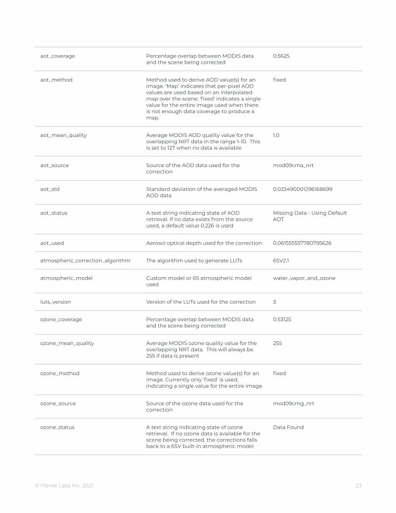
aot_coverage Percentage overlap between MODIS dataand the scene being corrected
0.5625
aot_method Method used to derive AOD value(s) for animage. ‘Map’ indicates that per-pixel AODvalues are used based on an interpolatedmap over the scene; 'fixed' indicates a singlevalue for the entire image used when thereis not enough data coverage to produce amap.
fixed
aot_mean_quality Average MODIS AOD quality value for theoverlapping NRT data in the range 1-10. Thisis set to 127 when no data is available
1.0
aot_source Source of the AOD data used for thecorrection
mod09cma_nrt
aot_std Standard deviation of the averaged MODISAOD data
0.033490001296168699
aot_status A text string indicating state of AODretrieval. If no data exists from the sourceused, a default value 0.226 is used
Missing Data - Using DefaultAOT
aot_used Aerosol optical depth used for the correction 0.061555557780795626
atmospheric_correction_algorithm The algorithm used to generate LUTs 6SV2.1
atmospheric_model Custom model or 6S atmospheric modelused
water_vapor_and_ozone
luts_version Version of the LUTs used for the correction 3
ozone_coverage Percentage overlap between MODIS dataand the scene being corrected
0.53125
ozone_mean_quality Average MODIS ozone quality value for theoverlapping NRT data. This will always be255 if data is present
255
ozone_method Method used to derive ozone value(s) for animage. Currently only 'fixed' is used,indicating a single value for the entire image
fixed
ozone_source Source of the ozone data used for thecorrection
mod09cmg_nrt
ozone_status A text string indicating state of ozoneretrieval. If no ozone data is available for thescene being corrected, the corrections fallsback to a 6SV built-in atmospheric model
Data Found
© Planet Labs Inc. 2021 23

ozone_std Standard deviation of the averaged MODISozone data.
0
ozone_used Ozone concentration used for thecorrection, in cm-atm
0.255
satellite_azimuth_angle Always defined to be 0.0 degrees and solarzenith angle measured relative to it
0.0
satellite_zenith_angle Satellite zenith angle, fixed to nadir pointing 0.0
solar_azimuth_angle Sun azimuth angle relative to satellite, indegrees
111.42044562850029
solar_zenith_angle Solar zenith angle in degrees 30.26950393461825
sr_version Version of the correction applied. 1.0
water_vapor_coverage Percentage overlap between MODIS dataand the scene being corrected
0.53215
water_vapor_mean_quality Average MODIS ozone quality value for theoverlapping NRT data in the range 1-10. Thisis set to 127 when no data is available
1.5294
water_vapor_method Method used to derive water vapor value(s)for an image. Currently only 'fixed' is used,indicating a single value for the entire image
fixed
water_vapor_source Source of the water vapor data used for thecorrection
mod09cma_nrt
water_vapor_status A text string indicating state of water vaporretrieval. If no water vapor data is availablefor the scene being corrected, thecorrections falls back to a 6SV built-inatmospheric model
Data Found
water_vapor_std Standard deviation of the averaged MODISAOD data
0.0587
water_vapor_used Water vapor concentration used for thecorrection in g/cm^2
4.0512
5.2 BASIC SCENES
The table below describes the GeoJSON metadata schema for PlanetScope Basic Scene products:
© Planet Labs Inc. 2021 24
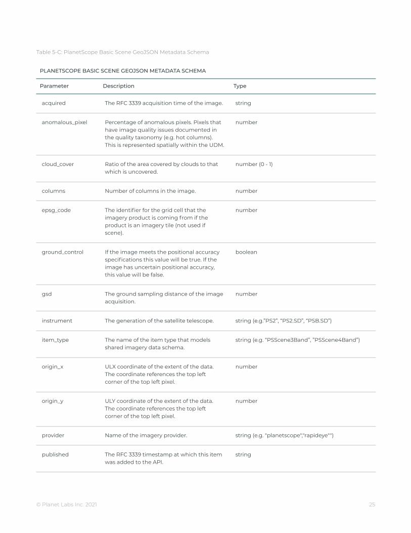
Table 5-C: PlanetScope Basic Scene GeoJSON Metadata Schema
PLANETSCOPE BASIC SCENE GEOJSON METADATA SCHEMA
Parameter Description Type
acquired The RFC 3339 acquisition time of the image. string
anomalous_pixel Percentage of anomalous pixels. Pixels thathave image quality issues documented inthe quality taxonomy (e.g. hot columns).This is represented spatially within the UDM.
number
cloud_cover Ratio of the area covered by clouds to thatwhich is uncovered.
number (0 - 1)
columns Number of columns in the image. number
epsg_code The identifier for the grid cell that theimagery product is coming from if theproduct is an imagery tile (not used ifscene).
number
ground_control If the image meets the positional accuracyspecifications this value will be true. If theimage has uncertain positional accuracy,this value will be false.
boolean
gsd The ground sampling distance of the imageacquisition.
number
instrument The generation of the satellite telescope. string (e.g.”PS2”, “PS2.SD”, “PSB.SD”)
item_type The name of the item type that modelsshared imagery data schema.
string (e.g. “PSScene3Band”, ”PSScene4Band”)
origin_x ULX coordinate of the extent of the data.The coordinate references the top leftcorner of the top left pixel.
number
origin_y ULY coordinate of the extent of the data.The coordinate references the top leftcorner of the top left pixel.
number
provider Name of the imagery provider. string (e.g. "planetscope","rapideye"")
published The RFC 3339 timestamp at which this itemwas added to the API.
string
© Planet Labs Inc. 2021 25

quality_category Metric for image quality. To qualify for“standard” image quality an image mustmeet a variety of quality standards, forexample: sun altitude greater than or equalto 10 degrees, off nadir view angle less than20 degrees, and saturated pixels fewer than20%. If the image does not meet thesecriteria it is considered “test” quality.
string: “standard” or “test”
rows Number of rows in the image. number
satellite_id Globally unique identifier of the satellitethat acquired the underlying imagery.
string
sun_azimuth Angle from true north to the sun vectorprojected on the horizontal plane indegrees.
number (0 - 360)
sun_elevation Elevation angle of the sun in degrees. number (0 - 90)
updated The RFC 3339 timestamp at which this itemwas updated in the API.
string
view_angle Spacecraft across-track off-nadir viewingangle used for imaging, in degrees with +being east and - being west.
number (-25 - +25)
© Planet Labs Inc. 2021 26

6. PRODUCT DELIVERY
All imagery products are made available via Application Processing Interface (API) and Graphical User Interface(GUI).
6.1 PLANET APPLICATION PROGRAMMING INTERFACES (APIS)
Planet offers REST API access that allows listing, filtering, and downloading of data to anyone using a valid APIkey. The metadata features described in this document are all searchable via our Data API and downloadablevia our Orders API.
Details on searching and ordering via Planet APIs are available in Planet’s Developer Center. Links are alsoavailable below.
● Catalog Overview (Items Types & Assets Types)● Search with Planet’s Data API● Order with Planet’s Orders API
6.2 PLANET EXPLORER GRAPHICAL USER INTERFACE (GUI)
Planet Explorer is a web-based tool that can be used to search Planet’s catalog of imagery, view metadata, anddownload full-resolution images. The interface and all of its features are built entirely on the externally availablePlanet API.
Planet Explorer allows users to:
1. View Timelapse Mosaics: A user can view Planet’s quarterly and monthly mosaics, and can zoom in upto zoom level 12 (38 m / pixel per OpenStreetMap)
2. Search: A user can Search for any location or a specific area of interest by entering into the input box ORby uploading a geometry file (Shapefile, GeoJSON, KML, or WKT).
3. Save Search: The Save functionality allows a user to save search criteria based on area of interest, dates,and filters.
4. Filter: A user can filter by a specific date range and/or customizing metadata parameters (e.g. estimatedcloud cover, GSD).
5. Zoom and Preview Imagery: Zoom and Preview allows a user to zoom in or out of the selected area andpreview imagery.
6. View Imagery Details: A user can review metadata details about each imagery product.
7. Download: The Download icon allows a user to download imagery based on subscription type.
© Planet Labs Inc. 2021 27

8. Draw Tools: These tools allow you to specify an area to see imagery results. The draw tool capabilitiesavailable are drawing a circle, drawing a rectangle, drawing a polygon, and/or limiting the size of thedrawing to the size of loadable imagery.
9. Imagery Compare Tool: The Compare Tool allows you to compare sets of Planet imagery from differentdates.
Planet will also enable additional functionality in the form of “Labs,” which are demonstrations of capabilitymade accessible to users through the GUI. Labs are active product features and will evolve over time based onPlanet technology evolution and user feedback.
6.3 PLANET ACCOUNT MANAGEMENT TOOLS
As part of the Planet GUI, an administration and account management tool is provided. This tool is used tochange user settings and to see past data orders. In addition, users who have administrator privileges will beable to manage users in their organization as well as review usage statistics.
The core functionality provided by account management tools are outlined below, and Planet may evolveAccount Management tools over time to meet user needs:
1. User Accounts Overview: Every user account on the Planet Platform is uniquely identified by an emailaddress. Each user also has a unique API key that can be used when interacting programmatically withthe Platform.
2. Organization and Sub-organization Overview: Every user on the Planet Platform belongs to oneorganization. The Platform also supports “sub-organizations,” which are organizations that are attachedto a “parent” organization. An administrator of a parent organization is also considered an administratoron all sub-organizations.
3. Account Privileges: Every user account on the Planet Platform has one of two roles: user oradministrator. An administrator has elevated access and can perform certain user managementoperations or download usage metrics that are not available to standard users. An administrator of aparent organization is also considered an administrator on all sub-organizations. Administrators canenable or disable administrator status and enable or disable users’ access to the platform altogether.
4. Orders and Usage Review: This tool records all part orders made and allows users and administrators toview and download past orders. Usage metrics are also made available, including imagery productsdownloaded and bandwidth usage. Usage metrics are displayed for each individual API key that is partof the organization.
© Planet Labs Inc. 2021 28
APPENDIX A – IMAGE SUPPORT DATA
All PlanetScope Ortho Tile Products are accompanied by a set of image support data (ISD) files. These ISD filesprovide important information regarding the image and are useful sources of ancillary data related to theimage. The ISD files are:
1. General XML Metadata File2. Unusable Data Mask File3. Usable Data Mask File
Each file is described along with its contents and format in the following sections.
1. GENERAL XML METADATA FILE
All PlanetScope Ortho Tile Products will be accompanied by a single general XML metadata file. This filecontains a description of basic elements of the image. The file is written in Geographic Markup Language (GML)version 3.1.1 and follows the application schema defined in the Open Geospatial Consortium (OGC) BestPractices document for Optical Earth Observation products version 0.9.3, seehttp://www.opengeospatial.org/standards/gml.
The contents of the metadata file will vary depending on the image product processing level. All metadata fileswill contain a series of metadata fields common to all imagery products regardless of the processing level.However, some fields within this group of metadata may only apply to certain product levels. In addition,certain blocks within the metadata file apply only to certain product types. These blocks are noted within thetable.
The table below describes the fields present in the General XML Metadata file for all product levels.
Table A-1: General XML Metadata File Field Descriptions
GENERAL XML METADATA FILE FIELD DESCRIPTIONS
Field Description
“metaDataProperty” Block
EarthObservationMetaData
Identifier Root file name of the image
acquisitionType Nominal acquisition
productType Product level listed in product filename
status Status type of image, if newly acquired or produced from a previouslyarchived image
downlinkedTo
© Planet Labs Inc. 2021 29

acquisitionStation X-band downlink station that received image from satellite
acquisitionDate Date and time image was acquired by satellite
archivedIn
archivingCenter Location where image is archived
archivingDate Date image was archived
archivingIdentifier Catalog ID of image
processing
processorName Name of ground processing system
processorVersion Version of processor
nativeProductFormat Native image format of the raw image data
license
licenseType Name of selected license for the product
resourceLink Hyperlink to the physical license file
versionIsd Version of the ISD
orderId Order ID of the product
tileId Tile ID of the product corresponding to the Tile Grid
pixelFormat Number of bits per pixel per band in the product image file
“validTime” Block
TimePeriod
beginPosition Start date and time of acquisition for source image take used to createproduct, in UTC
endPosition End date and time of acquisition for source image take used to createproduct, in UTC
“using” Block
EarthObservationEquipment
platform
shortName Identifies the name of the satellite platform used to collect the image
serialIdentifier ID of the satellite that acquired the data
orbitType Orbit type of satellite platform
instrument
© Planet Labs Inc. 2021 30
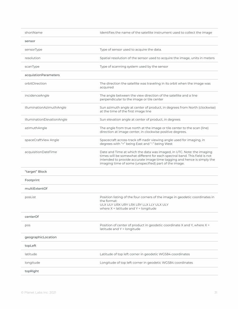
shortName Identifies the name of the satellite instrument used to collect the image
sensor
sensorType Type of sensor used to acquire the data.
resolution Spatial resolution of the sensor used to acquire the image, units in meters
scanType Type of scanning system used by the sensor
acquistionParameters
orbitDirection The direction the satellite was traveling in its orbit when the image wasacquired
incidenceAngle The angle between the view direction of the satellite and a lineperpendicular to the image or tile center
illuminationAzimuthAngle Sun azimuth angle at center of product, in degrees from North (clockwise)at the time of the first image line
illuminationElevationAngle Sun elevation angle at center of product, in degrees
azimuthAngle The angle from true north at the image or tile center to the scan (line)direction at image center, in clockwise positive degrees.
spaceCraftView Angle Spacecraft across-track off-nadir viewing angle used for imaging, indegrees with “+” being East and “-” being West
acquisitionDateTime Date and Time at which the data was imaged, in UTC. Note: the imagingtimes will be somewhat different for each spectral band. This field is notintended to provide accurate image time tagging and hence is simply theimaging time of some (unspecified) part of the image.
“target” Block
Footprint
multiExtentOf
posList Position listing of the four corners of the image in geodetic coordinates inthe format:ULX ULY URX URY LRX LRY LLX LLY ULX ULYwhere X = latitude and Y = longitude
centerOf
pos Position of center of product in geodetic coordinate X and Y, where X =latitude and Y = longitude
geographicLocation
topLeft
latitude Latitude of top left corner in geodetic WGS84 coordinates
longitude Longitude of top left corner in geodetic WGS84 coordinates
topRight
© Planet Labs Inc. 2021 31

latitude Latitude of top right corner in geodetic WGS84 coordinates
longitude Longitude of top right corner in geodetic WGS84 coordinates
bottomLeft
latitude Latitude of bottom left corner in geodetic WGS84 coordinates
longitude Longitude of bottom left corner in geodetic WGS84 coordinates
bottomRight
latitude Latitude of bottom right corner in geodetic WGS84 coordinates
longitude Longitude of bottom right corner in geodetic WGS84 coordinates
“resultOf” Block
EarthObservationResult
browse
BrowseInformation
type Type of browse image that accompanies the image product as part of theISD
referenceSystemIdentifier Identifies the reference system used for the browse image
fileName Name of the browse image file
product
fileName Name of image file.
productFormat File format of the image product
spatialReferenceSystem
epsgCode EPSG code that corresponds to the datum and projection information ofthe image
geodeticDatum Name of datum used for the map projection of the image
projection Projection system used for the image
projectionZone Zone used for map projection
resamplingKernel Resampling method used to produce the image. The list of possiblealgorithms is extendable
numRows Number of rows (lines) in the image
numColumns Number of columns (pixels) per line in the image
numBands Number of bands in the image product
rowGsd The GSD of the rows (lines) within the image product
© Planet Labs Inc. 2021 32

columnGsd The GSD of the columns (pixels) within the image product
radiometricCorrectionApplied Indicates whether radiometric correction has been applied to the image
geoCorrectionLevel Level of correction applied to the image
elevationCorrectionApplied Indicates the production elevation model used for ortho
atmosphericCorrectionApplied Indicates whether atmospheric correction has been applied to the image
atmosphericCorrectionParameters
mask
MaskInformation
type Type of mask file accompanying the image as part of the ISD
format Format of the mask file
referenceSystemIdentifier EPSG code that corresponds to the datum and projection information ofthe mask file
fileName File name of the mask file
cloudCoverPercentage Estimate of cloud cover within the image
cloudCoverPercentageQuot-ationMode
Method of cloud cover determination
unusableDataPercentage Percent of unusable data with the file
The following group is repeated for each spectral band included in the image product
bandSpecificMetadata
bandNumber Number (1-8) by which the spectral band is identified.
startDateTime Start time and date of band, in UTC
endDateTime End time and date of band, in UTC
percentMissingLines Percentage of missing lines in the source data of this band
percentSuspectLines Percentage of suspect lines (lines that contained downlink errors) in thesource data for the band
binning Indicates the binning used (across track x along track)
shifting Indicates the sensor applied right shifting
masking Indicates the sensor applied masking
radiometricScaleFactor Provides the parameter to convert the scaled radiance pixel value toradiance Multiplying the Scaled Radiance pixel values by the values,derives the Top of Atmosphere Radiance product. This value is a constant,set to 0.01
© Planet Labs Inc. 2021 33

reflectanceCoefficient The value is a multiplicative, when multiplied with the DN values, providesthe Top of Atmosphere Reflectance values
harmonizationTransform Provides coefficients to transform the Next-Generation PlanetScopesensor values to match those of the previous PlanetScope satellites
sourceSensor The new instrument to be transformed to the targetSensor
targetSensor The target instrument that the transform harmonizes values to
targetMeasure The physical unit that the harmonization transform is valid for
bandCoefficients Matrix of coefficients to transform band values to match those of thetargetSensor, in combination with the finalOffset
finalOffset An offset value for each band used in combination with thebandCoefficients to perform the transform
2. UNUSABLE DATA MASK FILE
The unusable data mask file provides information on areas of unusable data within an image (e.g. cloud andnon-imaged areas).
The pixel size after orthorectification will be 3.0m for PlanetScope Scenes. It is suggested that when using thefile to check for usable data, a buffer of at least 1 pixel should be considered. Each bit in the 8-bit pixel identifieswhether the corresponding part of the product contains useful imagery:
● Bit 0: Identifies whether the area contains blackfill in all bands (this area was not imaged). A value of “1”indicates blackfill.
● Bit 1: Identifies whether the area is cloud covered. A value of “1” indicates cloud coverage. Clouddetection is performed on a decimated version of the image (i.e. the browse image) and hence smallclouds may be missed. Cloud areas are those that have pixel values in the assessed band (Red, NIR orGreen) that are above a configurable threshold. This algorithm will:
○ Assess snow as cloud
○ Assess cloud shadow as cloud free
○ Assess haze as cloud free
● Bit 2: Identifies whether the area contains missing (lost during downlink) or suspect (contains down-link errors) data in band 1. A value of “1” indicates missing/suspect data. If the product does not includethis band, the value is set to “0”.
● Bit 3: Identifies whether the area contains missing (lost during downlink and hence blackfilled) orsuspect (contains downlink errors) data in the band 2. A value of “1” indicates missing/suspect data. Ifthe product does not include this band, the value is set to “0”.
© Planet Labs Inc. 2021 34
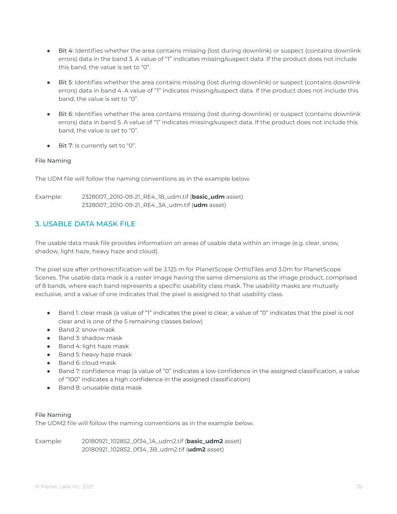
● Bit 4: Identifies whether the area contains missing (lost during downlink) or suspect (contains downlinkerrors) data in the band 3. A value of “1” indicates missing/suspect data. If the product does not includethis band, the value is set to “0”.
● Bit 5: Identifies whether the area contains missing (lost during downlink) or suspect (contains downlinkerrors) data in band 4. A value of “1” indicates missing/suspect data. If the product does not include thisband, the value is set to “0”.
● Bit 6: Identifies whether the area contains missing (lost during downlink) or suspect (contains downlinkerrors) data in band 5. A value of “1” indicates missing/suspect data. If the product does not include thisband, the value is set to “0”.
● Bit 7: Is currently set to “0”.
File Naming
The UDM file will follow the naming conventions as in the example below.
Example: 2328007_2010-09-21_RE4_1B_udm.tif (basic_udm asset)2328007_2010-09-21_RE4_3A_udm.tif (udm asset)
3. USABLE DATA MASK FILE
The usable data mask file provides information on areas of usable data within an image (e.g. clear, snow,shadow, light haze, heavy haze and cloud).
The pixel size after orthorectification will be 3.125 m for PlanetScope OrthoTiles and 3.0m for PlanetScopeScenes. The usable data mask is a raster image having the same dimensions as the image product, comprisedof 8 bands, where each band represents a specific usability class mask. The usability masks are mutuallyexclusive, and a value of one indicates that the pixel is assigned to that usability class.
● Band 1: clear mask (a value of “1” indicates the pixel is clear, a value of “0” indicates that the pixel is notclear and is one of the 5 remaining classes below)
● Band 2: snow mask● Band 3: shadow mask● Band 4: light haze mask● Band 5: heavy haze mask● Band 6: cloud mask● Band 7: confidence map (a value of “0” indicates a low confidence in the assigned classification, a value
of “100” indicates a high confidence in the assigned classification)● Band 8: unusable data mask
File NamingThe UDM2 file will follow the naming conventions as in the example below.
Example: 20180921_102852_0f34_1A_udm2.tif (basic_udm2 asset)20180921_102852_0f34_3B_udm2.tif (udm2 asset)
© Planet Labs Inc. 2021 35
Related Documents