PS 250 / PS 200 S Operating instructions en Mode d’emploi fr Manual de instrucciones es Manual de instruções pt Printed: 10.12.2013 | Doc-Nr: PUB / 5135501 / 000 / 01

Welcome message from author
This document is posted to help you gain knowledge. Please leave a comment to let me know what you think about it! Share it to your friends and learn new things together.
Transcript

*2037331*
2037
331
PS 250 /PS 200 SOperating instructions enMode d’emploi frManual de instrucciones esManual de instruções pt
Printed: 10.12.2013 | Doc-Nr: PUB / 5135501 / 000 / 01

Green
Red
PS 200 Ferroscan
PSA 93
1
Printed: 10.12.2013 | Doc-Nr: PUB / 5135501 / 000 / 01

PS 200 Ferroscan
2
PS 200 Ferroscan
3
4
Printed: 10.12.2013 | Doc-Nr: PUB / 5135501 / 000 / 01

ORIGINAL OPERATING INSTRUCTIONS
PS 250 ferroscan systemPS 200 S ferroscan
It is essential that the operating instructionsare read before the tool is operated for thefirst time.Always keep these operating instructions to-gether with the tool.Ensure that the operating instructions arewith the tool when it is given to other persons.
Contents Page1 General information 12 Description 23 Items supplied, accessories, spare parts 34 Technical data 75 Safety instructions 106 Before use 117 Operation 118 Care and maintenance 289 Troubleshooting 2910 Disposal 3111 Manufacturer’s warranty 3212 FCC statement / IC statement 32
1 These numbers refer to the corresponding illustra-tions. The illustrations can be found on the fold-out coverpages. Keep these pages open while studying the oper-ating instructions.
In these operating instructions, the designation “the tool”always refers to PS 200 S Ferroscan. The designation“PS 250 Ferroscan system” applies to the whole systemconsisting of the PS 200 S scanner, PSA 100 monitor andPROFIS Ferroscan PC software for data evaluation. Thedesignation “PS 200 S Ferroscan”, on the other hand,applies only to the scanner.
Components 1
@PS 200 S scanner
;PSA 60 soft pouch
=PSA 100 monitor
%PSA 55 infrared adapter
&PSA 63 hand strap
(PSA 92 USB data cable
)PUA 95 Micro USB data cable
+PSA 93 headset with microphone
§PSA 64 soft pouch
/PSA 62 carrying strap
:PSA 80 battery pack
·PSA 82 battery pack
$PUA 81 AC adapter
£PUA 80 charger
|Supply cord
¡PSA 10/11 reference grid set
QPUA 90 adhesive tape
WFolding rule
EPSA 70 brush
RPUA 70 marking pen set
TPROFIS Ferroscan software
ZPS 250 toolbox
1 General information1.1 Safety notices and their meaningDANGERDraws attention to imminent danger that will lead toserious bodily injury or fatality.
WARNINGDraws attention to a potentially dangerous situation thatcould lead to serious personal injury or fatality.
CAUTIONDraws attention to a potentially dangerous situation thatcould lead to slight personal injury or damage to theequipment or other property.
NOTEDraws attention to an instruction or other useful informa-tion.
1.2 Explanation of the pictograms and otherinformation
Warning signs
Generalwarning
Warning:electricity
Warning:caustic
substances
en
1
Printed: 10.12.2013 | Doc-Nr: PUB / 5135501 / 000 / 01
Symbols
Read theoperatinginstructionsbefore use.
Return wastematerial forrecycling.
Location of identification data on the toolThe type designation and serial number can be found onthe type identification plate on the tool. Make a note ofthis data in your operating instructions and always referto it when making an enquiry to your Hilti representativeor service department.
Type:
Generation: 02
Serial no.:
2 Description2.1 Use of the product as directedThe tool is intended to be used for locating reinforcing bars in concrete, measuring depth of concrete cover andestimating the diameter of the bars in the uppermost layer in accordance with the specifications detailed in thetechnical data provided in these operating instructions.The tool is designed for professional use and may be operated, serviced and maintained only by trained, authorizedpersonnel. This personnel must be informed of any special hazards that may be encountered. The tool and its ancillaryequipment may present hazards when used incorrectly by untrained personnel or when used not as directed.Observe the information printed in the operating instructions concerning operation, care and maintenance.Take the influences of the surrounding area into account. Do not use the tool or appliance where there is a risk of fireor explosion.Modification of the tool or tampering with its parts is not permissible.
2.2 PSA 55 infrared adapterThe PSA 55 infrared adapter is used to store scans before they are subsequently transferred to a computer. Theadapter has a storage capacity of approx. 100 scans.
2.3 ApplicationsThe tool can be used for various non-destructive detection applications on steel-reinforced concrete structures (e.g.locating reinforcing bars in the uppermost layers, measuring depth of concrete cover and estimating the diameterof the bars detected). The scanning mode used depends on the application. These fall broadly into the followingcategories:Application Scanning modeAvoiding damage to reinforcing bars when drilling or core drilling Quickscan detection, Imagescan or
BlockscanDetermining the position / number and diameter of bars for load-bearing capacity checks or depth of cover measurements
Imagescan
Determining depth of concrete cover over large areas Quickscan recording
2.4 Using the systemThe system functions by running the scanner directly over the surface of the structure. The data collected is stored inthe scanner until it can be transferred to the monitor. The monitor is used for storing large amounts of data and forviewing the scans. It can also be used for on-the-spot evaluation of scans. The data can also be downloaded to aPC. The PC software offers advanced evaluation options, data archiving functions and the ability to quickly print outcomplete reports.
2.5 Quickscan detectionThe scanner is moved across the surface at right angles to the reinforcing bars. The position and approximate depthof the reinforcing bars can be determined and marked right away on the surface of the concrete.
en
2
Printed: 10.12.2013 | Doc-Nr: PUB / 5135501 / 000 / 01

2.6 Quickscan detection with accurate depth measurementBefore scanning, the operator is required to enter values for the diameter of the reinforcing bars and the spacingbetween the bars. The scan is then carried out as described for Quickscan detection.
2.7 Quickscan recordingData is recorded automatically as the scanner is moved over the surface of the concrete. This data is subsequentlytransferred to the monitor where it can be evaluated and the average depth of cover determined. If the data isdownloaded to a PC, the information can be evaluated, archived and a report printed. Further evaluation optionsallow Quickscan recordings to be imported and evaluated automatically, statistical evaluations prepared and scansdisplayed in the form of large-area evaluations.
2.8 ImagescanA reference grid is attached at the area of interest using the adhesive tape supplied. After selecting the Imagescanmode with the scanner, the rows and columns of the grid are scanned following the instructions on the screen. Thedata is transferred to the monitor where the image can be viewed and evaluated. The position of the reinforcing barsrelative to the concrete surface is indicated. Bar diameter can be estimated and bar depth determined. If the data isdownloaded to the PC application, this information can be evaluated as on the monitor, with the additional advantageof allowing a series of points to be recorded along with associated depth and diameter, and the data saved forfuture use. Reports can also be printed. Further evaluation options allow Imagescans to be imported and evaluatedautomatically, statistical evaluations prepared and scans displayed in the form of large-area evaluations.
2.9 BlockscanA reference grid is attached at the area of interest using the adhesive tape supplied. After selecting Blockscan mode,the user is prompted to select the first area to scan. An Imagescan is then made. After completing the Imagescan, theuser is prompted to select the next area to scan. This should be adjacent to the previous area. Attach the grid and thenscan as before. This procedure can be repeated for up to 3 x 3 Imagescans. The data is transferred to the monitor. TheImagescans are automatically stitched together to form a larger image. The reinforcement layout can then be viewedover the whole area. Individual Imagescans can be selected for evaluation by “zooming in”. If the data is downloadedto the PC application, this information can be evaluated as on the monitor, with the additional advantage of allowing aseries of points to be recorded along with associated depth and diameter, and the data saved for future use. Reportscan also be printed.
3 Items supplied, accessories, spare parts3.1 Items supplied3.1.1 PS 250 Ferroscan system
Num-ber
Designation Comments
1 PS 200 S scanner 1
1 PSA 60 soft pouch Soft pouch for the PS 200 S scanner
1 PSA 100 monitor1
1 PSA 64 soft pouch Soft pouch for the PSA 100 monitor
1 PSA 63 hand strap For the PS 200 S scanner
1 PSA 55 infrared adapter For temporary storage of data from the PS 200 S scanner
1 PUA 95 Micro USB data cable Data cable for connecting the PSA 55 infrared adapter to a PC
1 PSA 97 data module Contains the operating instructions in electronic form and is used toupdate the PSA 100 monitor
1 Version depends on the country-specific version of the system ordered.
2 May or may not be included in the items supplied, depending on the country-specific version of the system ordered.
en
3
Printed: 10.12.2013 | Doc-Nr: PUB / 5135501 / 000 / 01

Num-ber
Designation Comments
1 PSA 92 USB data cable PSA 100 monitor to PC
1 PSA 93 headset with micro-phone
For the PSA 100 monitor
2 AA-size alkaline batteries For the PSA 55 infrared adapter
1 PSA 80 battery pack NiMH battery pack for the PS 200 S scanner
1 PUA 80 charger Charger for the PSA 80 battery pack
1 Supply cord1 Supply cord for the PUA 80 charger
1 PSA 82 battery pack Li-ion battery pack for the PSA 100 monitor
1 PUA 81 AC adapter AC adapter for charging the PSA 100 monitor
1 PSA 75 brush For removing dust and particles of concrete before applyingPUA 90 adhesive tape
1 Cleaning cloth
1 Folding rule2
5 PSA 10/11 reference grid1 For making an Imagescan
1 PUA 90 adhesive tape For attaching the reference grid to a dry, dust-free concrete surface
1 PUA 70 marking pen set Set of 6 red and 6 black marking pens for marking the grid positionand object position
1 PROFIS Ferroscan software PC software on CD-ROM for the PS 250 Ferroscan system /PS 200 S Ferroscan set
1 PSA/PUA operating instruc-tions
1 PSA 100 operating instructions
1 PS 200 S Ferroscan / PS 250Ferroscan system operatinginstructions
1 PS 200 S manufacturer’s cer-tificate
1 PSA 100 manufacturer’s certifi-cate
1 PS 250 toolbox Plastic toolbox with insert for the PS 250 Ferroscan system
1 Version depends on the country-specific version of the system ordered.
2 May or may not be included in the items supplied, depending on the country-specific version of the system ordered.
3.1.2 PS 200 S Ferroscan set
Num-ber
Designation Comments
1 PS 200 S scanner 1
1 PSA 55 infrared adapter For temporary storage of data from the PS 200 S scanner
1 PSA 60 soft pouch Soft pouch for the PS 200 S scanner
1 Version depends on the country-specific version of the system ordered.
2 May or may not be included in the items supplied, depending on the country-specific version of the system ordered.
en
4
Printed: 10.12.2013 | Doc-Nr: PUB / 5135501 / 000 / 01

Num-ber
Designation Comments
1 PSA 62 carrying strap
1 PSA 63 hand strap Soft pouch for the PS 200 S scanner
2 AA-size alkaline batteries
1 PSA 80 battery pack NiMH battery pack for the PS 200 S scanner
1 PUA 80 charger Charger for the PSA 80 battery pack
1 PUA 95 Micro USB data cable Data cable for connecting the PSA 55 infrared adapter to a PC5 PSA 10/11 reference grid1 For making an Imagescan
1 PUA 90 adhesive tape For attaching the reference grid to a dry, dust-free concrete surface
1 PUA 70 marking pen set Set of 6 red and 6 black marking pens for marking the grid positionand object position
1 PROFIS Ferroscan software PC software on CD-ROM for the PS 250 Ferroscan system /PS 200 S Ferroscan set
1 PSA/PUA operating instruc-tions
1 PS 200 S Ferroscan / PS 250Ferroscan system operatinginstructions
1 PSA 75 brush For removing dust and particles of concrete before applyingPUA 90 adhesive tape
1 Folding rule2
1 Cleaning cloth
1 PS 200 S toolbox Plastic toolbox with insert
1 PS 200 S manufacturer’s cer-tificate
1 Version depends on the country-specific version of the system ordered.
2 May or may not be included in the items supplied, depending on the country-specific version of the system ordered.
3.1.3 PS 200 S scanner
Num-ber
Designation Comments
1 PS 200 S scanner 1
1 PSA 60 soft pouch Soft pouch for the PS 200 S scanner
1 PSA 80 battery pack NiMH battery pack for the PS 200 S scanner
1 PSA 63 hand strap For the PS 200 S scanner
1 PSA/PUA operating instruc-tions
1 PS 200 S Ferroscan / PS 250Ferroscan system operatinginstructions
1 PS 200 S manufacturer’s cer-tificate
1 Version depends on the country-specific version of the system ordered.
en
5
Printed: 10.12.2013 | Doc-Nr: PUB / 5135501 / 000 / 01
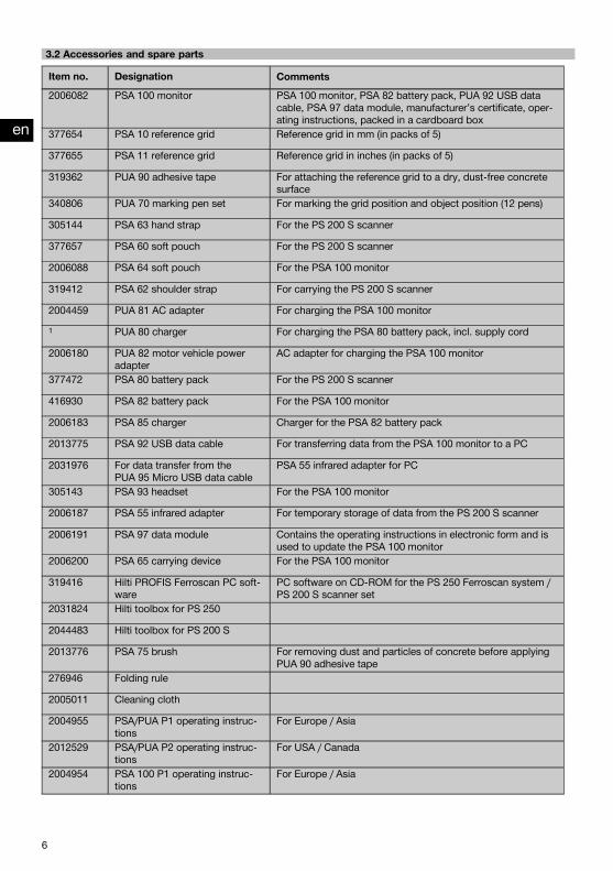
3.2 Accessories and spare parts
Item no. Designation Comments2006082 PSA 100 monitor PSA 100 monitor, PSA 82 battery pack, PUA 92 USB data
cable, PSA 97 data module, manufacturer’s certificate, oper-ating instructions, packed in a cardboard box
377654 PSA 10 reference grid Reference grid in mm (in packs of 5)
377655 PSA 11 reference grid Reference grid in inches (in packs of 5)
319362 PUA 90 adhesive tape For attaching the reference grid to a dry, dust-free concretesurface
340806 PUA 70 marking pen set For marking the grid position and object position (12 pens)
305144 PSA 63 hand strap For the PS 200 S scanner
377657 PSA 60 soft pouch For the PS 200 S scanner
2006088 PSA 64 soft pouch For the PSA 100 monitor
319412 PSA 62 shoulder strap For carrying the PS 200 S scanner
2004459 PUA 81 AC adapter For charging the PSA 100 monitor1 PUA 80 charger For charging the PSA 80 battery pack, incl. supply cord
2006180 PUA 82 motor vehicle poweradapter
AC adapter for charging the PSA 100 monitor
377472 PSA 80 battery pack For the PS 200 S scanner
416930 PSA 82 battery pack For the PSA 100 monitor
2006183 PSA 85 charger Charger for the PSA 82 battery pack
2013775 PSA 92 USB data cable For transferring data from the PSA 100 monitor to a PC
2031976 For data transfer from thePUA 95 Micro USB data cable
PSA 55 infrared adapter for PC
305143 PSA 93 headset For the PSA 100 monitor
2006187 PSA 55 infrared adapter For temporary storage of data from the PS 200 S scanner
2006191 PSA 97 data module Contains the operating instructions in electronic form and isused to update the PSA 100 monitor
2006200 PSA 65 carrying device For the PSA 100 monitor
319416 Hilti PROFIS Ferroscan PC soft-ware
PC software on CD-ROM for the PS 250 Ferroscan system /PS 200 S scanner set
2031824 Hilti toolbox for PS 250
2044483 Hilti toolbox for PS 200 S
2013776 PSA 75 brush For removing dust and particles of concrete before applyingPUA 90 adhesive tape
276946 Folding rule
2005011 Cleaning cloth
2004955 PSA/PUA P1 operating instruc-tions
For Europe / Asia
2012529 PSA/PUA P2 operating instruc-tions
For USA / Canada
2004954 PSA 100 P1 operating instruc-tions
For Europe / Asia
en
6
Printed: 10.12.2013 | Doc-Nr: PUB / 5135501 / 000 / 01

Item no. Designation Comments2004815 PSA 100 P2 operating instruc-
tionsFor USA / Canada
2037330 PS 200 S Ferroscan / PS 250Ferroscan system P1 operatinginstructions
For Europe / Asia
2037331 PS 200 S Ferroscan / PS 250Ferroscan system P2 operatinginstructions
For USA / Canada
4 Technical data4.1 Ambient conditionsOperating temperature range -10…+50°C (+14…+122 °F)
Storage temperature -20…+60°C (−4…+140 °F)
Relative humidity (operation) Max. 90%, no condensationDust and water protection (operation) IP54
Impact resistance (tool in toolbox) EN 60068-2-29
Dropping EN 60068-2-32
Vibration (not in operation) MIL-STD 810 D
4.2 System scanning performanceFor reliable scanning results, the following conditions must be fulfilled:
Concrete surface smooth and flat.Reinforcement not corroded.Reinforcement lying parallel to concrete surface.Concrete does not contain additives or components with magnetic properties.Reinforcing bars lying within ± 5° of right angle to the scanning direction.Reinforcing bars are not welded.Neighboring bars are of similar diameter.Neighboring bars are at a similar depth.Accuracy specifications are valid only for the first layer of reinforcement.No interfering influences from external magnetic fields or objects nearby with magnetic properties.Bars have relative magnetic permeability of 85–105.The scanner wheels are clean and free from sand and grit etc.All 4 scanner wheels are in contact and rotate when the scanner is moved across the object to be scanned.The bars comply with one of the following standards (depending on system item no.):
Standards for steel reinforcing barsItem no. Standard Origin / applicability of the stan-
dard2044434, 2044439, 2044473,2044435, 2044472, 377646,377652
DIN 488 European Union and all other coun-tries not listed below
2044436, 2044474, 377649 ASTM A 615 / A 615M‑01b United States of America, Taiwan,Latin America and Central America
2044437, 2044475, 377650 CAN/CSA-G30, 18-M92 Canada
en
7
Printed: 10.12.2013 | Doc-Nr: PUB / 5135501 / 000 / 01
Item no. Standard Origin / applicability of the stan-dard
2044438, 2044470, 2044476,2044478, 377651
JIS G 3112 Japan, Korea
2044471, 2044479, 408056 GB 50010-2002 China
2078650, 2078660, 2078670 GOST 5781-82 Russia
2078651, 2078661, 2078671 BIS 1786:1985 India
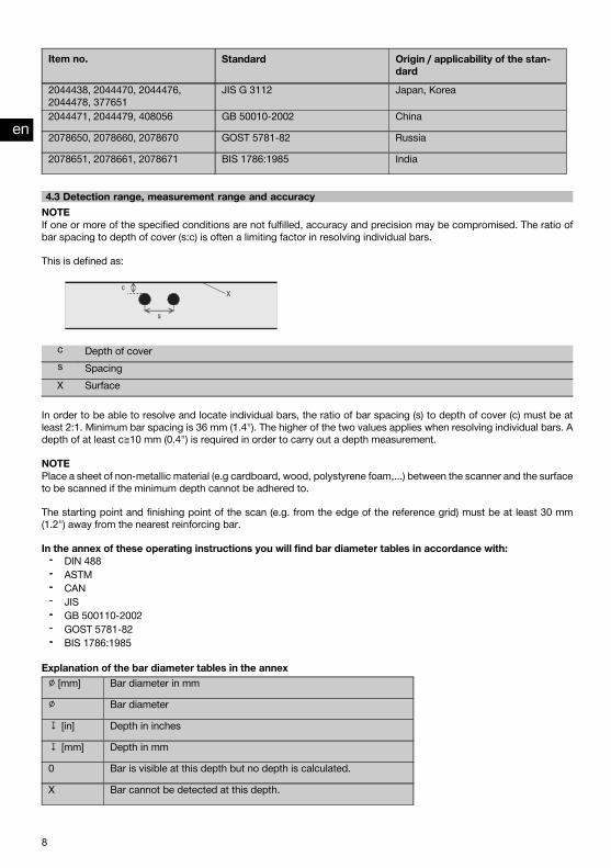
4.3 Detection range, measurement range and accuracyNOTEIf one or more of the specified conditions are not fulfilled, accuracy and precision may be compromised. The ratio ofbar spacing to depth of cover (s:c) is often a limiting factor in resolving individual bars.
This is defined as:
c Depth of covers SpacingX Surface
In order to be able to resolve and locate individual bars, the ratio of bar spacing (s) to depth of cover (c) must be atleast 2:1. Minimum bar spacing is 36 mm (1.4"). The higher of the two values applies when resolving individual bars. Adepth of at least c≧10 mm (0.4") is required in order to carry out a depth measurement.
NOTEPlace a sheet of non-metallic material (e.g cardboard, wood, polystyrene foam,...) between the scanner and the surfaceto be scanned if the minimum depth cannot be adhered to.
The starting point and finishing point of the scan (e.g. from the edge of the reference grid) must be at least 30 mm(1.2") away from the nearest reinforcing bar.
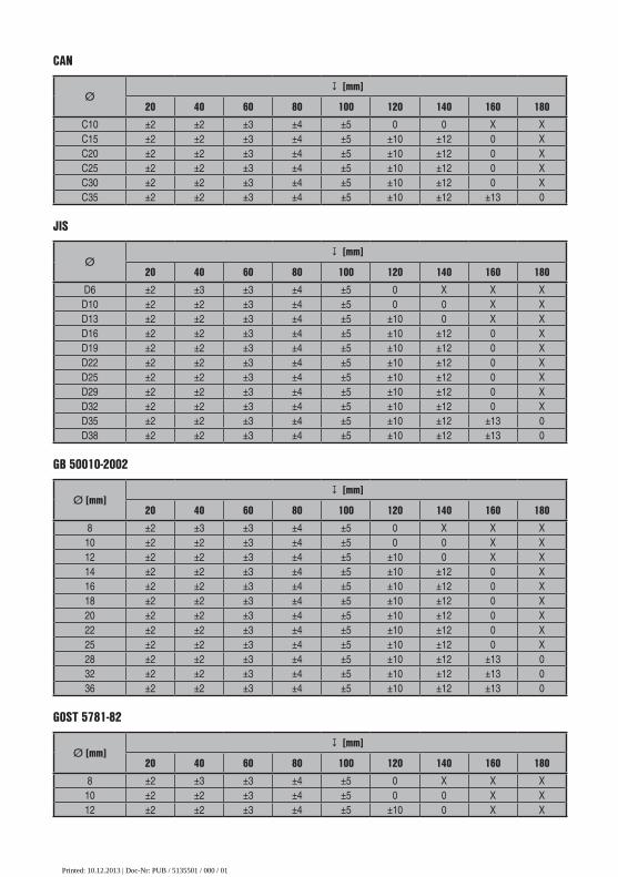
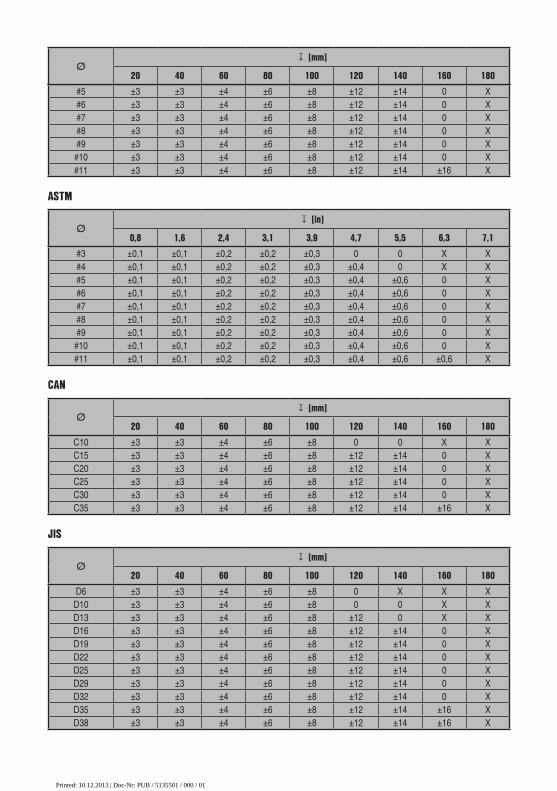
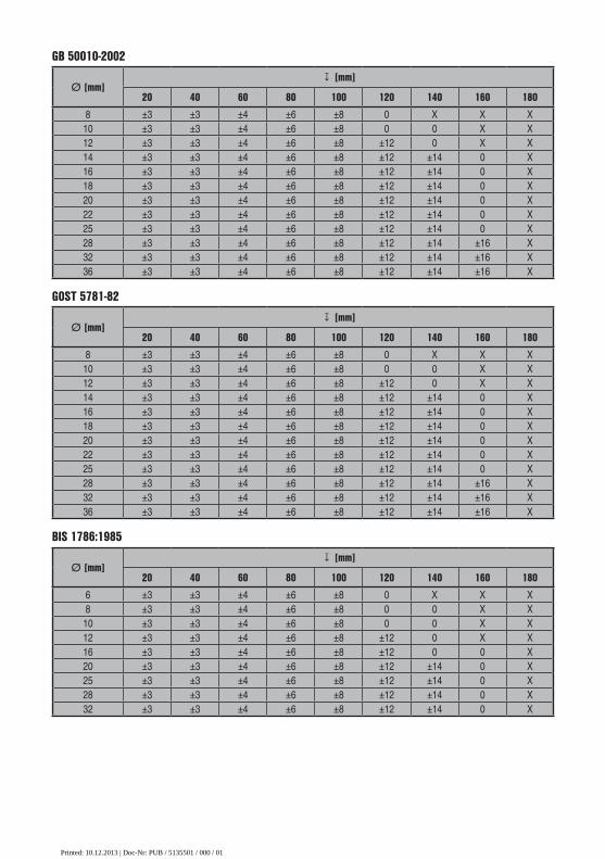
In the annex of these operating instructions you will find bar diameter tables in accordance with:DIN 488ASTMCANJISGB 500110-2002GOST 5781-82BIS 1786:1985
Explanation of the bar diameter tables in the annex∅ [mm] Bar diameter in mm
∅ Bar diameter
↧ [in] Depth in inches
↧ [mm] Depth in mm
0 Bar is visible at this depth but no depth is calculated.
X Bar cannot be detected at this depth.
en
8
Printed: 10.12.2013 | Doc-Nr: PUB / 5135501 / 000 / 01

The value indicates the typical accuracy of the depth measurement (deviationfrom actual) in mm or, respectively, in inches.
4.3.1 Imagescan and Blockscan: Rebar diameter is knownPlease refer to the bar diameter tables in the annex (1.).
4.3.2 Imagescan and Blockscan: Rebar diameter is not knownPlease refer to the bar diameter tables in the annex (2.).
4.3.3 Quickscan recording: Rebar diameter is knownPlease refer to the bar diameter tables in the annex (3.).
4.3.4 Quickscan detection with depth measurement: Rebar diameter is knownPlease refer to the bar diameter tables in the annex (4.).
4.3.5 Quickscan detectionDepth measurement is accurate to within ±10% of the effective depth.
4.3.6 Accuracy of bar diameter measurement± 1 standard diameter when rebar spacing : depth of cover ≥ 2 : 1. Bar diameter measurement is possible only atdepths of up to 60 mm (2.4").
4.3.7 Reinforcing bar location accuracyBar center locating accuracy (all modes): Typically ± 3 mm (0.12") relative to the measured position, when the ratio ofbar spacing : depth of cover is ≥ 1.5:1.
4.4 Technical data for PS 200 S scannerMaximum scanning speed 0.5 m/sec (1.64 ft/s)
Memory type Built-in flash memory for data
Memory capacity 9 Imagescans plus up to 30 m (98 ft) of recordedQuickscan (max. 10 scans)
Screen type / size LCD / 50 × 37 mm (2" x 1.5")
Screen resolution 128 × 64 pixels
Dimensions 260 × 132 × 132 mm (10.2 x 5.2 x 5.2")
Weight (with PSA 80 battery pack) 1.4 kg (3.09 lb)
Minimum battery life (with PSA 80 battery pack) 8 hours under typical conditions
Automatic power-off 5 min. after last press of a button
Backup battery type / life Lithium / 10 years (typically)
Scanner-monitor data interface Infrared
Scanner-monitor data transfer time ≦16 s for 9 images, ≦2 s for 1 image
Infrared range Typically 0.3 m (1 ft)
Infrared output power Max. 500 mW
4.5 Technical data for PSA 55 infrared adapterBattery 1 x 1.5 V AAA
Dimensions 90 x 50 x 28 mm (3.5 x 2 x 1.1")
Weight 65 g (0.14 lb)
en
9
Printed: 10.12.2013 | Doc-Nr: PUB / 5135501 / 000 / 01

Scanner - adapter data interface IrDa
Adapter - computer data interface USB
5 Safety instructionsIn addition to the information relevant to safety givenin each of the sections of these operating instructions,the following points must be strictly observed at alltimes.
5.1 Intended usea) The tool and its ancillary equipment may present
hazards when used incorrectly by untrained per-sonnel or when used not as directed.
b) To avoid the risk of injury, use only genuine Hiltiaccessories and additional equipment.
c) Modification of the tool or tamperingwith its partsis not permissible.
d) Observe the information printed in the operat-ing instructions concerning operation, care andmaintenance.
e) Do not render safety devices ineffective and donot remove information and warning notices.
f) Check the condition of the tool before use. If thetool is found to be damaged, have it repaired at aHilti Service Center.
g) In particularly critical situations where measurementshave safety and structural stability implications, al-ways check results by removing material from thesurface of the structure and physically checking theposition, depth and diameter of reinforcement at keypositions.
h) When drilling at or near to a bar indicated by the sys-tem, never drill deeper than the bar depth indicated.
5.2 Proper organization of the workplace
a) Keep the workplace tidy. Objects which couldcause injury should be removed from the work-ing area. Untidiness at the workplace can lead toaccidents.
b) Keep other persons, especially children, awayfrom the area in which the work is being carriedout.
c) Wear non-skid shoes.d) Avoid unfavorable body positions when working
from ladders. Make sure you work from a safestance and stay in balance at all times.
e) Only use the tool within the defined limits.f) Check with a qualified person that it is safe to drill at
a specified point before beginning drilling.g) Do not use the tool where there is a risk of fire or
explosion.
h) Make sure that the toolbox is properly secured duringtransport and does not present a risk of injury.
5.3 Electromagnetic compatibilityAlthough the tool complies with the strict requirements ofthe applicable directives, Hilti cannot entirely rule out thepossibility of interference to the tool caused by powerfulelectromagnetic radiation, leading to incorrect operation.Accuracy must be checked by taking measurements byother means when working under such conditions orif you are unsure. Likewise, Hilti cannot rule out thepossibility of interference with other devices (e.g. aircraftnavigation equipment).
5.4 General safety precautions5.4.1 Mechanical safety precautionsa) Check the tool for damage before use. If the tool
is found to be damaged, have it repaired at a HiltiService Center.
b) You must check the accuracy of the tool after ithas been dropped or subjected to other mechan-ical stresses.
c) When the tool is brought into a warm environmentfrom very cold conditions, or vice-versa, allow itto become acclimatized before use.
d) Although the tool is protected against the entry ofmoisture, it should be wiped dry before being putaway in its transport container.
5.4.2 Electrical safety precautionsa) Avoid short circuiting the battery terminals.Check
that the terminals on the battery pack and in the toolare free from foreign objects before inserting thebattery pack. Short circuiting the battery terminalspresents a risk of fire, explosion and chemical burns.
b) Make sure that the outer surfaces of the batterypack are clean and dry before inserting it in thecharger. Observe the operating instructions forthe charger.
c) Use only the battery pack specified in these operatinginstructions.
d) Batteries that have reached the end of their life mustbe disposed of safely and correctly to avoid environ-mental pollution.
e) Remove the battery pack before transporting the toolor storing it for a long period of time. Inspect thebattery pack for any signs of leakage or damagebefore reusing it.
f) To avoid pollution of the environment, the toolmust be disposed of in accordance with the cur-
en
10
Printed: 10.12.2013 | Doc-Nr: PUB / 5135501 / 000 / 01

PS 200 F
erro
scan
rently applicable national regulations. Consult themanufacturer if you are unsure of how to proceed.
5.4.3 Liquids
Caustic liquids may leak from defective batteries. Avoidcontact with these liquids. In case of skin contact, washthe area affected with soap and plenty of water. In caseof eye contact, rinse the eyes immediately with water andsubsequently consult a doctor.
5.5 Requirements to be met by usersa) The tool may be operated, serviced and repaired
only by authorized, trained personnel. This personnelmust be informed of any special hazards that may beencountered.
b) Concentrate on your work. Stay alert. Pay atten-tion to what you are doing. Approach the workwith common sense. Do not use the tool if youare not concentrating.
c) Do not use the tool if it is defective.d) If you are unsure of the scan results, consult a Hilti
specialist before proceeding.e) Observe all warning and information messages dis-
played by the scanner and monitor.
5.6 Scanning requirements and limitationsa) Always check the accuracy of the tool before com-
mencing work on structures where measurementshave safety and structural stability implications. Scana reinforcing bar of known location, depth and di-ameter and check the results against the accuracyspecifications.
b) Do not use the PS 200 S scanner if the wheels donot turn freely or appear to be worn. Contact Hilti forrepair information. The wheels may also be cleanedor replaced by the user.
c) Always check how the tool is configured beforeusing it.
d) Apply only light pressure to the scanner whenmovingit across the surface.
e) Reinforcement that lies beneath the uppermost layerof reinforcement may not be detected.
f) Remove all metal items of jewelry such as rings, pen-dants, bracelets, etc. before commencing scanning.
6 Before use
6.1 Charging the battery packUse the PUA 80 charger to charge the PSA 80 batterypack. Full instructions are contained in the charger oper-ating instructions. The battery pack must be charged for14 hours before first use.
6.1.1 Inserting and removing the battery packCAUTIONThe battery pack must slide easily into the scanner. Donot use force when inserting the battery pack into thescanner as this may damage the battery pack and/or thescanner.
Check that the battery pack is correctly aligned with thescanner. When the battery pack end cap is facing you,the large groove in the battery pack must be on the left.
Push the battery pack into the opening as far as it will go.Turn the end cap clockwise until it clicks into place.To remove the battery pack, turn the end cap anti-clockwise as far as it will go. Pull the battery pack out ofthe scanner.
7 Operation
7.1 Carrying and using the systemCAUTIONThe temperature inside a motor vehicle exposed to theheat of the sun can easily exceed the maximum permis-sible storage temperature for the PS 250 Ferroscan sys-tem. Some of the components of the PS 250 Ferroscansystem may suffer damage if exposed to temperaturesexceeding 60°C (140°F).
The scanner can be used without the monitor for scan-ning, or the monitor can be carried in the PSA 64 softpouch. The first option is advantageous when workingin areas that are difficult to access and maximum mo-bility is required, such as on a scaffold or ladder. Whenscanner memory is full (9 Imagescans made, 1 completeBlockscan or 30 mm (98 ft) of Quickscan have beenrecorded) the data can be transferred to the PSA 55infrared adapter or the PSA 100 monitor. The monitor
en
11
Printed: 10.12.2013 | Doc-Nr: PUB / 5135501 / 000 / 01

1
2
3
4
5
1 3
2
can be kept nearby (e.g. at the foot of the scaffold, in avehicle, in the site office etc.). When the user intends tomake more scans than the scanner is capable of storing
in its memory and wishes to avoid repeated journeys tothe monitor, the PSA 55 infrared adapter can be usedor the monitor attached to a belt or carried using theshoulder strap supplied.
7.2 Operating the scanner7.2.1 Control panel and displayControl panel
@Arrow but-tons
Toggle up or down in options orvalues.
;Confirmbutton
Confirms a value or a selection.
=On/off but-ton
Switches the tool on or off.
%Cancel but-ton
Cancels an input, cancels thepath being scanned or goesback one step within a menu.
&Recordbutton
Starts or stops a recording.
Display@
Menu area. Functions that can be selectedusing the Arrow and Confirmbuttons
;Status in-formation
Information such as batterycharge status and memorystatus.
=Variablearea.
This is where feedback / infor-mation for the user is displayed,e.g. scanning mode, bar depth,scanning progress, etc.
7.2.2 Switching on and offPress the on / off button to switch the scanner on or off.The scanner can be switched off only when the main menu is displayed. To reach this screen, press the Cancel buttonrepeatedly until the main menu is displayed.
7.2.3 Main menuThe system always starts in the main menu. All scanning functions and set-up options are selected here. The batterycharge status is displayed at the top of the screen together with the memory status. The various scan modes andsettings menus are displayed as symbols on the left side of the screen. Use the Arrow buttons to toggle betweenthese options. Press the Confirm button to confirm the selected option.
en
12
Printed: 10.12.2013 | Doc-Nr: PUB / 5135501 / 000 / 01
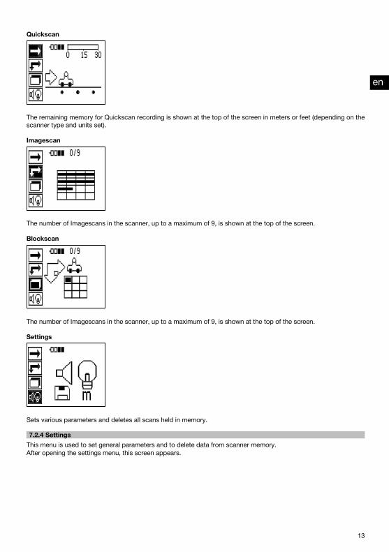
Quickscan
The remaining memory for Quickscan recording is shown at the top of the screen in meters or feet (depending on thescanner type and units set).
Imagescan
The number of Imagescans in the scanner, up to a maximum of 9, is shown at the top of the screen.
Blockscan
The number of Imagescans in the scanner, up to a maximum of 9, is shown at the top of the screen.
Settings
Sets various parameters and deletes all scans held in memory.
7.2.4 SettingsThis menu is used to set general parameters and to delete data from scanner memory.After opening the settings menu, this screen appears.
en
13
Printed: 10.12.2013 | Doc-Nr: PUB / 5135501 / 000 / 01

The Arrow buttons are used to select the options. The selected option can be confirmed / activated by pressing theConfirm button and the Cancel button then pressed to return to the main menu.
7.2.4.1 Set display backlightSelect the backlight adjustment function by pressing the Confirm button. Use the Arrow buttons to toggle betweenthe individual options. Press the Confirm button to select the desired option and press the Cancel button to return tothe settings menu.
Switch backlight on
Switch backlight off
Backlight is controlled automatically. With this option, the backlight is switched off automatically after 5 minutes if nobutton is pressed during this time and is switched back on again the next time a button is pressed.
en
14
Printed: 10.12.2013 | Doc-Nr: PUB / 5135501 / 000 / 01

7.2.4.2 Adjusting the volume
Sets the volume level of the audible signal during scanning. Use the Arrow buttons to toggle between the variousoptions. Press the Confirm button to select the desired option and press the Cancel button to return to the settingsmenu.
7.2.4.3 Setting the unitsOn systems with the item nos. 2044436, 2044474 and 377649 can the unit of measure used for scanning can beconfigured by the user. Use the Arrow buttons to toggle between the various options. Press the Confirm button toselect the desired option and press the Cancel button to return to the settings menu.
Metric (mm or m, as appropriate)
Imperial (feet, as appropriate)
7.2.4.4 Deleting dataDeletes all scan data stored in the scanner. This function is available only if data is contained in memory. If data iscontained in memory, the bar shown next to the diskette symbol is filled. The bar is shown empty when no data iscontained in memory.
NOTEDeleting memory contents presents a risk of losing data. Data that has not been transferred to the monitor beforedeletion will be permanently lost.
en
15
Printed: 10.12.2013 | Doc-Nr: PUB / 5135501 / 000 / 01
Press the Down arrow button followed by the Confirm button to delete data. Alternatively, press the Cancel button toreturn to the settings menu.
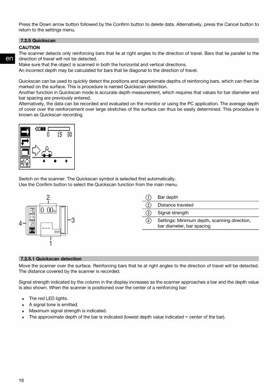
7.2.5 QuickscanCAUTIONThe scanner detects only reinforcing bars that lie at right angles to the direction of travel. Bars that lie parallel to thedirection of travel will not be detected.Make sure that the object is scanned in both the horizontal and vertical directions.An incorrect depth may be calculated for bars that lie diagonal to the direction of travel.
Quickscan can be used to quickly detect the positions and approximate depths of reinforcing bars, which can then bemarked on the surface. This is procedure is named Quickscan detection.Another function in Quickscan mode is accurate depth measurement, which requires that values for bar diameter andbar spacing are previously entered.Alternatively, the data can be recorded and evaluated on the monitor or using the PC application. The average depthof cover over the reinforcement over large stretches of the surface can thus be easily determined. This procedure isknown as Quickscan recording.
Switch on the scanner. The Quickscan symbol is selected first automatically.Use the Confirm button to select the Quickscan function from the main menu.
@Bar depth
;Distance traveled
=Signal strength
%Settings: Minimum depth, scanning direction,bar diameter, bar spacing
7.2.5.1 Quickscan detectionMove the scanner over the surface. Reinforcing bars that lie at right angles to the direction of travel will be detected.The distance covered by the scanner is recorded.
Signal strength indicated by the column in the display increases as the scanner approaches a bar and the depth valueis also shown. When the scanner is positioned over the center of a reinforcing bar:
The red LED lights.A signal tone is emitted.Maximum signal strength is indicated.The approximate depth of the bar is indicated (lowest depth value indicated = center of the bar).
en
16
Printed: 10.12.2013 | Doc-Nr: PUB / 5135501 / 000 / 01

The bar is positioned along the center line of the scanner and may be marked on the surface using a PUA 70 markingpen. Depth measurement accuracy can be increased by entering the correct rebar diameter or by switching to accuratedepth measurement measuring mode (see 7.2.5.2).
7.2.5.2 Quickscan with accurate depth measurement
The measuring mode “Quickscan with accurate depth measurement” is selected by pressing the Confirm button.
The correct diameter must be known and previously entered.The bar spacing distance must also be entered if within the 36 mm≦s≦120 mm (1.4"≦s≦4.7") range (see 4.3). Thisvalue can be taken from building plans, confirmed by chipping away a channel in the concrete to view the bars, ormeasured using Quickscan detection.
NOTEA rebar spacing distance s≦36 mm (1.4") (see 4.3) cannot be measured.
The bar spacing distance can be calculated automatically using the Quickscan detection function by searching forthe center of the bar and pressing the red Record button when the scanner is over the mid point of the bar. Find themid point of the next bar and then press the Record button again. Bar spacing is then calculated automatically andrecorded.
en
17
Printed: 10.12.2013 | Doc-Nr: PUB / 5135501 / 000 / 01
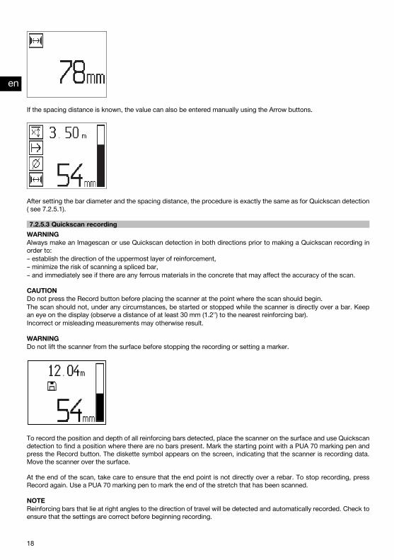
If the spacing distance is known, the value can also be entered manually using the Arrow buttons.
After setting the bar diameter and the spacing distance, the procedure is exactly the same as for Quickscan detection( see 7.2.5.1).
7.2.5.3 Quickscan recordingWARNINGAlways make an Imagescan or use Quickscan detection in both directions prior to making a Quickscan recording inorder to:– establish the direction of the uppermost layer of reinforcement,– minimize the risk of scanning a spliced bar,– and immediately see if there are any ferrous materials in the concrete that may affect the accuracy of the scan.
CAUTIONDo not press the Record button before placing the scanner at the point where the scan should begin.The scan should not, under any circumstances, be started or stopped while the scanner is directly over a bar. Keepan eye on the display (observe a distance of at least 30 mm (1.2") to the nearest reinforcing bar).Incorrect or misleading measurements may otherwise result.
WARNINGDo not lift the scanner from the surface before stopping the recording or setting a marker.
To record the position and depth of all reinforcing bars detected, place the scanner on the surface and use Quickscandetection to find a position where there are no bars present. Mark the starting point with a PUA 70 marking pen andpress the Record button. The diskette symbol appears on the screen, indicating that the scanner is recording data.Move the scanner over the surface.
At the end of the scan, take care to ensure that the end point is not directly over a rebar. To stop recording, pressRecord again. Use a PUA 70 marking pen to mark the end of the stretch that has been scanned.
NOTEReinforcing bars that lie at right angles to the direction of travel will be detected and automatically recorded. Check toensure that the settings are correct before beginning recording.
en
18
Printed: 10.12.2013 | Doc-Nr: PUB / 5135501 / 000 / 01

A stretch of up to 30 m (98 ft) in length can be recorded before it is necessary to transfer the data to the PSA 100monitor or the PSA 55 infrared adapter. It is also possible to record several separate stretches (max. 10) that add upto a maximum of 30 m (98 ft).
The data recorded can be transferred to the monitor for analysis ( see section 7.4.1).
7.2.5.4 Quickscan settingsThe Quickscan settings are shown on the left hand side of the display. The settings can be made before making aQuickscan or a Quickscan with accurate depth measurement. Use the Arrow buttons and Confirm button to accessthe settings.
Limited depth scanNOTEThis measurement mode allows rebars to be located within a specified depth range.
NOTEWhen using the tool in this mode, the preset depth must take a clearance distance from the rebar into account.
Minimum depthUse this setting when scanning a surface and looking specifically for bars that are located within a certain depth. Forexample, if checking for 40 mm (1.6") minimum depth of cover, set the value to 40 mm (1.6"). (For quality assurancemeasurements add an extra 2 mm (0.08") to account for any accuracy limitations). A signal tone is emitted and theLED lights only if a reinforcing bar located within 40 mm (1.6") of the surface is detected.
CAUTIONBefore making a scan, check to ensure that the depth range restriction is set correctly or deactivated if this feature isnot required.
Use the Arrow buttons to select the minimum depth function and then press Confirm.
Minimum depth function disabled.
When the value is set to "0", the function is deactivated and appears as above. Use the Arrow buttons to enter thedesired depth value and then confirm the setting by pressing the Confirm button. The system returns to the mainmenu.
NOTEIf reinforcing bars are located at depths greater than the minimum depth set, no signal tone is emitted and no LEDlights.
Scanning directionThis setting is used to set the direction in which Quickscan recording is performed. Although they have no directeffect on any measurement values later obtained from the monitor or PC application, the settings help to ensure that
en
19
Printed: 10.12.2013 | Doc-Nr: PUB / 5135501 / 000 / 01

individual Quickscan recordings are subsequently correctly displayed in Hilti PROFIS Ferroscan MAP (data evaluationand presentation application) and that the depth values correspond with the actual surface of the structure. Thismakes it easier to subsequently locate the positions of areas with inadequate cover. The scanning direction is savedtogether with each scan.
Select the desired scanning direction and press the Confirm button.
Bar diameterThis setting must be made in order to obtain an accurate depth of cover measurement (= rebar depth). Depth can bemeasured accurately only when correct rebar diameter has been entered.
Use the Arrow buttons to select the bar diameter function and then press the Confirm button.
If no bar diameter is selected, the scanner will take the average diameter value for the relevant standard setting rangeand calculate the depth accordingly.
CAUTIONUse the “Unknown diameter” function only under exceptional circumstances as the results of the scan may bedistorted considerably if rebars of a different diameter have, in fact, been incorporated in the structure.
Average bar diameter according to standardsStandard ∅DIN 488 16 mm (0.63")
ASTM A 615 / A 615M‑01b #7
CAN / CSA-G30, 18-M92 C 20
JIS G 3112 D 22
GB 50012-2002 18 mm (0.71")
GOST 5781-82 18 mm (0.71")
BIS 1786:1985 16 mm (0.63")
NOTEThe bar diameter previously set will be saved in the scanner when switching it off. Check each time before using thescanner that the rebar diameter has been preset correctly.
en
20
Printed: 10.12.2013 | Doc-Nr: PUB / 5135501 / 000 / 01

7.2.5.5 Setting a markerThe surfaces of many structures contain obstacles that make it impossible to record the scan without lifting thescanner from the surface. Examples of such obstacles are piers or columns on a wall, door openings, expansion joints,pipes, scaffold bars, corners etc.
If an obstacle is encountered, a marker can be set. This interrupts the scan and allows the user to lift the scanner awayfrom the surface, place it beyond the obstruction and then continue scanning. It also indicates where certain objectsare located within a scan, providing additional information that creates a reference between the scan data and theactual surface.
To set a marker, press and hold the Confirm button while in recording mode. The diskette symbol will be crossed out,indicating that recording has been suspended and a marker has been set.
CAUTIONDue to interruption of the recorded signal, scanning results are less accurate immediately before and after the pointwhere a marker is set.Do not interrupt the scan at the position of a reinforcing bar.
Then lift the scanner from the surface while keeping the Confirm button pressed. If necessary, mark the position onthe surface using a PUA 70 marking pen. Place the scanner back on the surface beyond the obstacle, release theConfirm button and continue scanning. The marker will be shown as a vertical line in the scan data when viewed onthe monitor or in the PC application.
7.2.6 ImagescanImagescan is used to create an image of the reinforcement layout. The depth and diameter of the bars can bedetermined or, respectively, estimated.A reference grid must first be fixed to the wall. Use the adhesive tape supplied for this purpose. This tape adheres wellto concrete and can be torn off the roll by hand in the lengths required. For most surfaces, a 10 cm (4") length of tapeat each corner is adequate to secure the grid. If the concrete surface is very damp or dusty, use the brush supplied toclean off any dirt and dust. The reference grid may then have to be attached by applying a strip of tape along the fulllength of each edge.
Alternatively, a grid can be marked directly on the surface. Using a straight edge (such as a piece of wood) as aguide, mark out a 4 x 4 grid with the parallel lines spaced at intervals of 150 mm (6"). The holes punched in the paperreference grid can also be used to mark the positions of the grid lines on the concrete surface.
Switch the scanner on and select the Imagescan symbol. The battery level is displayed together with the number ofImagescans currently held in memory (a maximum of 9).
Select Imagescan from the main menu.The Imagescan screen is displayed.
en
21
Printed: 10.12.2013 | Doc-Nr: PUB / 5135501 / 000 / 01

150
150
5
1
2
Æ
PS
200 S Ferroscan
Æ
PS
200
S F
erro
scan
A representation of the grid appears on the screen with a suggested starting point (triangle). This is always at upperleft and will be suitable for most scans. Image data will be generated only for areas of the grid that have been scannedboth vertically and horizontally. In some cases, obstacles in the scan area may prevent this (e.g. a pipe penetrating abeam). The starting point may be changed in such cases in order to allow the area to be scanned optimally. Use theArrow buttons to change the starting point if necessary.
Place the scanner on the grid at the starting point shown by the blinking arrow. Ensure the alignment marks on thescanner are aligned correctly with the reference grid as shown above.
NOTEIncorrect alignment of the scanner on the reference grid may lead to the bar positions being incorrect in the imagegenerated.
Press Record and move the scanner along the first row. Scanning progress is indicated by a thick black line thatadvances across the display as the scanner is moved over the surface.
en
22
Printed: 10.12.2013 | Doc-Nr: PUB / 5135501 / 000 / 01

Æ
PS
20
0 S
Fe
rros
ca
n
Æ
PS
200 S
Ferr
oscan
The scanner emits a double beep at the end of the row and automatically stops recording. This procedure should berepeated for each row and column while observing the instructions shown in the display.
When all rows have been completed, the columns should also be scanned in the same way.
The scanning operation for any row or column may be interrupted before reaching the end by pressing Record again.This may be necessary if an obstacle prevents the full path being scanned. Similarly, an entire row or column may beskipped by starting and stopping the recording without running the scanner over the grid.Please note that no image will be created for areas of the reference grid that are not scanned in both directions.
It is possible to repeat the previous row or column by pressing Cancel. This may be necessary if the user is notsure whether the path to be scanned has been followed accurately or if the scanner slipped out of position. PressingCancel a second time aborts the scan and the system then returns to the main menu. Press Confirm to save the scan.Pressing Cancel after scanning the last column or row will cause the scan to be deleted.
When the scan is complete, press the Confirm button to return to the main menu. The data can be transferred to themonitor for viewing and evaluation ( see 7.4.1).
7.2.7 BlockscanBlockscan automatically stitches Imagescans together to provide an impression of the reinforcement layout over alarge area. The exact bar position, depth and diameter can also be determined on the monitor by selecting eachImagescan individually.
en
23
Printed: 10.12.2013 | Doc-Nr: PUB / 5135501 / 000 / 01

150
150
300
450
600
300 450 600
5 6 7 8
1
2
3
4
Attach the reference grid in the same way as for an Imagescan. Use a PUA 70 marking pen to mark the edges or thepunched holes at the end of each reference grid for the transition to the next grid, as shown below. Any additionalreference grids required should be attached to the wall so that their edges correspond and are in alignment with eachother.
Switch the scanner on and use the Arrow buttons to select the Blockscan symbol from the main menu. The batterylevel is displayed together with the number of Imagescans currently held in memory (a maximum of 9).
A representation of a Blockscan is shown on the screen. Each square represents an Imagescan. Up to 3 x 3 Imagescanscan be made. Use the Arrow buttons to select the position of the first Imagescan to be made. Press Confirm to beginthe first Imagescan. Note that the coordinates of any points on the Blockscan will be referenced from the upper leftcorner.
For details of how to carry out the Imagescan, see 7.2.6. When the Imagescan is complete, the system returns to theBlockscan screen.
en
24
Printed: 10.12.2013 | Doc-Nr: PUB / 5135501 / 000 / 01

150
150
300
450
600
300 450 600
5 6 7 8
1
2
3
4
150
150
300
450
600
300 450 600
5 6 7 8
1
2
3
4
The completed Imagescan is shown shaded.
Select the next Imagescan position and repeat the scanning procedure. Imagescans already made may be repeatedsimply by reselecting the area to scan and carrying out the Imagescan again. The data will be overwritten. Once all theImagescans have been recorded, or the maximum number of scans that can be held in memory is reached (9), pressthe Cancel button to return to the main menu. Transfer the data to the monitor for viewing and analysis ( see 7.4.1).
NOTEPressing the Cancel button twice causes the recorded Imagescan to be deleted. The screen then returns to the mainmenu.
7.3 PSA 55 infrared adapter7.3.1 Before first useNOTEInstall the Hilti PROFIS Ferroscan 5.7 software (or a higherversion) on your PC/laptop. The date and time must beset before using the PSA 55 IR adapter for the first timein order to ensure that the scan data subsequently showsthe correct date and time.
To do this, use the PUA 95 Micro USB cable toconnect the PSA 55 IR adapter to the computer.Start the Hilti PROFIS Ferroscan application.Go to “Tools”, “Workflow” and then select “Set PSA55 date and time”.The date and time are then set in the PSA 55 IRadapter.
NOTEThe device driver is installed together with the HiltiPROFIS Ferroscan (V 5.7) software. If this is not thecase, the device driver must be installed manually byrunning the “setup.exe” file located in the “Drivers” folderon the PSA 55 IR adapter.
7.3.2 Operating the PSA 55 infrared adapterThe scans can be transferred to the adapter via theinfrared interface and from there to the PC/laptop.
Switch the adapter on or off by pressing the on / offbutton for about 3 seconds.
The LED display on the adapter can indicate the followingstatuses:
en
25
Printed: 10.12.2013 | Doc-Nr: PUB / 5135501 / 000 / 01

The green LED lights constantly: The adapter isswitched on and is ready for operation.The red LED blinks rapidly: Battery charge state islow.The green LED blinks: The adapter has just beenswitched on.The green LED blinks: Data transfer in progress.The red LED blinks and the adapter switches itselfoff: Memory is 95% full.
7.4 Data transfer7.4.1 Transferring data from the scanner to the
monitor 2
NOTEEnsure that the correct project is selected on the monitorbefore transferring data.
NOTECheck that the windows over the infrared ports arefree from dirt, dust and grease and are not excessivelyscratched before commencing data transfer. Failure todo so may result in reduced data transfer range or mayprevent data transfer.
Data is transferred from the scanner to the monitor us-ing the infrared connection. The infrared windows aresituated at the ends of scanner and the monitor.
Data can be transferred at any time when the scannerand monitor are switched on, the PS 200 S scanner isdisplaying the main menu and data transfer by infrared isactivated on the monitor.The project into which the data is to be copied is selectedon the monitor under Projects.Then select Import and confirm “From PS 200 S” bypressing theOKbutton. The infrared symbol then appearsin the status area of the PSA 100 monitor.
Bring the scanner and monitor close together so thatthe infrared windows are facing each other. The twodevices recognize each other automatically and establishcommunication.
This screen appears on the scanner and a beep sounds:
Press the Confirm button on the scanner to begin import-ing all scan data into the selected project.
This screen appears on the scanner while data transferis in progress and the red LED on the scanner blinkscontinuously.
Data transfer takes between 1 and 15 seconds, depend-ing on the number and length of scans contained in thescanner.
This screen is displayed by the scanner when data trans-fer is complete:
Press the Confirm button on the scanner again to end thedata transfer procedure.The scan data in the scanner is then deleted automati-cally.
7.4.2 Transferring data from the scanner to theadapter 3
DANGERUse the adapter only indoors. Avoid moisture ingress.
CAUTIONCheck that the windows over the infrared ports arefree from dirt, dust and grease and are not excessivelyscratched before commencing data transfer.Failure to do so may result in reduced data transfer rangeor may prevent data transfer.
Data is transferred from the scanner to the adapter us-ing the infrared connection. The infrared windows aresituated at the ends of scanner and the adapter.
NOTEThe maximum range of the infrared connection is approx-imately 30 cm (11.8"). The maximum permissible anglebetween the scanner and monitor for successful datatransmission at close ranges (up to 10 cm (4")) is ± 50°relative to the axis of the infrared port on the adapter.At a distance of 15 cm (6") this angle is reduced to ±30°. At a distance of 30 cm (11.8") the scanner must beaccurately aligned with the monitor to ensure successfuldata transmission.
Bring the scanner and adapter close together so thatthe infrared windows are facing each other. The twodevices recognize each other automatically and establishcommunication. The following screen appears on thescanner and a beep sounds:
en
26
Printed: 10.12.2013 | Doc-Nr: PUB / 5135501 / 000 / 01

Press the Confirm button on the scanner to begin datatransfer. The following may be observed while data trans-fer is in progress:
The green LED on the adapter blinks rapidly to indicatethat data transfer is in progress. The red LED on thescanner blinks continuously.Data transfer takes between 1 and 15 seconds, depend-ing on the number and length of scans contained in thescanner. The LED on the adapter lights green again whendata transfer is finished.This screen is displayed by the scanner when data trans-fer is complete.
All scan data has then been successfully transferred.Press the Confirm button on the scanner to delete thedata in the scanner and return to the main menu.
7.4.3 Transferring data from the adapter to thecomputer 4
NOTETo ensure data security, data integrity and to avoid mal-functions, use only the PUA 95Micro USB cable suppliedby Hilti.
The PUA 95 Micro USB data cable is used to transferdata from the adapter to the computer.The adapter can be removed once data transfer is com-plete.
NOTEIn order to remove the PSA 55 adapter safely, we rec-ommend use of the “Remove hardware safely” functionof the operating system. This helps prevent loss of dataintegrity.
7.4.4 Transferring data from the monitor to thecomputer 4
NOTETo ensure data security, data integrity and to avoid mal-functions, use only the PSA 92 Micro USB cable suppliedby Hilti.
The PSA 92 USB data cable is used to transfer data fromthe monitor to the computer.
7.5 Tips for scanning and evaluationThe object is too narrow to scan or reinforcement istoo close to an outside edge to be scanned properly.
Use a thin sheet of non-metallic material (e.g cardboard,wood, polystyrene foam,...) as an overlay that extendsbeyond the edge. The scanner can then be moved overthe sheet to beyond the edge of the structure. Note thatthe thickness of the board must be deducted from anydepth measurements. The thickness of the board canbe entered in the PC application. This value will then beautomatically deducted from any depth measurements.
The surface is rough.
Rough surfaces (e.g. concrete surfaces with exposedaggregates) cause additional noise in the signal and maymean that the depth or diameter of a bar cannot bedetermined. In such cases it is also advantageous toscan through a thin overlay board. Also in this case, thethickness of the board must be deducted from any depthmeasurements.
Interference in images
Interference in images may occur due to:
Scraps of reinforcement in the concreteTie wires where rebars crossAggregates with ferromagnetic propertiesEnds of bars lying parallel to the scanning plane
en
27
Printed: 10.12.2013 | Doc-Nr: PUB / 5135501 / 000 / 01

Ends of bars lying at right angles to the scanningplane (standing bars)
NOTEDiameters and depths calculated in the area where inter-ference occurs must be treated with caution as they maybe inaccurate.
Scanning columns and beams for making penetra-tions
In cases where the reinforcement must not be damaged,ensure that Imagescans are made on at least three sides
of the component in order to ensure that shear bars(placed at an angle in the concrete) can also be detected.
Simple diameter checkA simple, rough check of the diameter of the bars in thefirst layer can be made by deducting the depth of thesecond perpendicular layer from that of the first. Thisassumes however that the two layers touch each otheror are at least very close.
7.6 PC softwareTheHilti PROFIS Ferroscan PC application provides func-tions for enhanced analysis, easy creation of reports, dataarchival, image and data export to other PC applicationsas well as automated batch processing of large volumesof data.The Hilti PROFIS Ferroscan MAP application makes itpossible to merge large volumes of data, allowing thecreation and evaluation of large-area images coveringareas of up to 45 x 45 m (148 x 148 ft).
Installation instructions can be found on the Hilti PROFISFerroscan software CD-ROM. Detailed information aboutusing the PC application can be found in the Help menu.
8 Care and maintenance8.1 Cleaning and dryingCAUTIONDo not use liquids other than alcohol or water. Otherliquids may damage plastic parts.
Clean the parts of the tool only with a clean, soft cloth.Moisten the cloth with pure alcohol or a little water ifnecessary.
8.2 StorageDo not store the tool when it is wet.Dry and clean the tool, its case and accessories beforestoring.Remove the batteries before storing.After storing for a long period of time, carry out a mea-surement check before use.Observe the temperature limits when storing your equip-ment. This is particularly important in winter / summer ifthe equipment is kept inside a motor vehicle (-25°C to+60°C / -13°F to +140°F).
8.3 TransportDANGERRemove the battery before storing or transporting thetool.
Always use the original Hilti toolbox when transportingthe tool.
8.4 Removing / replacing the scanner wheelsCAUTIONDo not overtighten the screw when refitting the wheel asthis may result in damage to the wheel and axle. Replaceonly one wheel at a time.
The scanner wheels can be removed either for cleaningor replacement.Use a 2.5 mm (¹⁄₈") Allen wrench to loosen and removethe screw at the wheel axle.Carefully pull the wheel off the axle while holding the op-posite end of the axle or other wheel. If necessary, cleanthe casing and/or wheel carefully see 8.1 before refittingthe wheel to the axle and reinserting and tightening thescrew.
8.5 Hilti Calibration ServiceWe recommend that the tool is checked by the HiltiCalibration Service at regular intervals in order to ver-ify its reliability in accordance with standards and legalrequirements.Use can be made of the Hilti Calibration Service at anytime, but checking at least once a year is recommended.The Calibration Service provides confirmation that thetool is in conformance, on the day it is tested, with thespecifications given in the operating instructions.After checking, a calibration sticker applied to the tool anda calibration certificate providewritten verification that the
en
28
Printed: 10.12.2013 | Doc-Nr: PUB / 5135501 / 000 / 01

tool is operating in accordance with the manufacturer’sspecification.
Calibration certificates are always required by companiescertified according to ISO 900x.Your local Hilti Center or representative will be pleasedto provide further information.
9 TroubleshootingMessage displayed Fault Possible cause Remedy
Symbol appears while us-ing Quickscan detectionmode.
The scanner is not record-ing.
The maximum scanningspeed of 0.5 m/s (1.64ft/s) has been exceeded.
Press the Confirm buttonand repeat the scan.Move the scanner overthe surface more slowly.
Symbol appears whilemaking a Quickscanrecording.
The scanner is not record-ing.
The maximum scanningspeed of 0.5 m/s (1.64ft/s) has been exceeded.
Press the Confirm button.Repeat the scanning op-eration from the start-ing point or from the lastpoint at which a markerwas set.Move the scanner overthe surface more slowly.
Symbol appears whilemaking an Imagescan.
The scanner is not record-ing.
The maximum scanningspeed of 0.5 m/s (1.64ft/s) has been exceeded.
Press the Confirm button.Scan the row or columnagain.Move the scanner overthe surface more slowly.
Symbol appears.
The scanner is not record-ing.
This symbol may appearif the scanner is moved inthe wrong direction whenin Quickscan record-ing mode, i.e. you beginscanning, for example,from right to left but atsome point during theQuickscan recording youmove the scanner to theright.
Press the Confirm buttonand repeat the scan.Move the scanner in thecorrect direction.NOTEThe warning does not ap-pear immediately, onlywhen a movement of 15cm (6") or more in thewrong direction occurs.
en
29
Printed: 10.12.2013 | Doc-Nr: PUB / 5135501 / 000 / 01
Message displayed Fault Possible cause Remedy
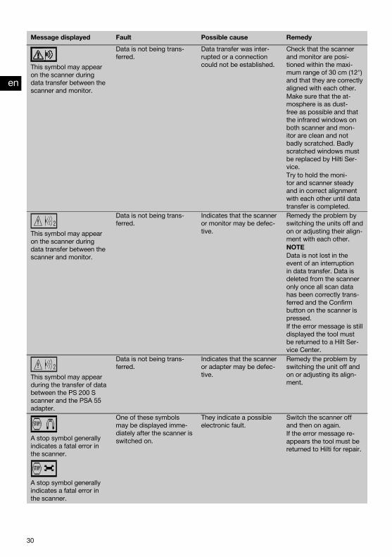
This symbol may appearon the scanner duringdata transfer between thescanner and monitor.
Data is not being trans-ferred.
Data transfer was inter-rupted or a connectioncould not be established.
Check that the scannerand monitor are posi-tioned within the maxi-mum range of 30 cm (12")and that they are correctlyaligned with each other.Make sure that the at-mosphere is as dust-free as possible and thatthe infrared windows onboth scanner and mon-itor are clean and notbadly scratched. Badlyscratched windows mustbe replaced by Hilti Ser-vice.Try to hold the moni-tor and scanner steadyand in correct alignmentwith each other until datatransfer is completed.
This symbol may appearon the scanner duringdata transfer between thescanner and monitor.
Data is not being trans-ferred.
Indicates that the scanneror monitor may be defec-tive.
Remedy the problem byswitching the units off andon or adjusting their align-ment with each other.NOTEData is not lost in theevent of an interruptionin data transfer. Data isdeleted from the scanneronly once all scan datahas been correctly trans-ferred and the Confirmbutton on the scanner ispressed.If the error message is stilldisplayed the tool mustbe returned to a Hilt Ser-vice Center.
This symbol may appearduring the transfer of databetween the PS 200 Sscanner and the PSA 55adapter.
Data is not being trans-ferred.
Indicates that the scanneror adapter may be defec-tive.
Remedy the problem byswitching the unit off andon or adjusting its align-ment.
A stop symbol generallyindicates a fatal error inthe scanner.
A stop symbol generallyindicates a fatal error inthe scanner.
One of these symbolsmay be displayed imme-diately after the scanner isswitched on.
They indicate a possibleelectronic fault.
Switch the scanner offand then on again.If the error message re-appears the tool must bereturned to Hilti for repair.
en
30
Printed: 10.12.2013 | Doc-Nr: PUB / 5135501 / 000 / 01

Message displayed Fault Possible cause Remedy
An exclamation mark in-dicates either an errorcaused by the operatoror an error that can besolved by the operator.
This symbol may appearwhen trying to enter theImagescan or Blockscanscanning mode, when try-ing to begin a new Im-agescan within Blockscanscanning mode or whentrying to start Quickscanrecording.
This indicates that thememory allocated to theoperation is full and thatno more data can bestored.
In this situation, the datamust either be transferredto the monitor or deletedfrom scanner memory.NOTEDeleting the contents ofscanner memory may re-sult in data loss. Data thathas not been transferredto the monitor will be per-manently deleted.
Fault Possible cause RemedyThe scanner doesn't start. The battery pack is not charged. Change the battery.
The contacts on the battery pack or inthe scanner are dirty.
Clean the contacts.
The battery pack is old or defective,or the maximum number of chargingcycles has been exceeded.
Contact Hilti Service.
The scanner doesn't run freely. The wheels are dirty or dusty. Remove the wheels and casing andclean the parts.
The drive belt or gear teeth are worn. Contact Hilti Service.The scanner operates only fora short time before the batterypack is exhausted.
The battery pack is old or defective,or the maximum number of chargingcycles has been exceeded.
Contact Hilti Service.
The scan date and time are notcorrect.
The Hilti PROFIS Ferroscan applica-tion was not used to set the date.
Install Hilti PROFIS Ferroscan V 5.7(or a higher version) and start the ap-plication.Use the PSA 95 data cable toconnect the adapter and then go to“Tools”, “Workflow”, “Set PSA 55date and time” and set the currentdate and time.
The date and time cannot beset.
The date and time cannot be set asno device driver was found.
Install the driver manually: Use thePSA 95 data cable to connect thePSA 55 adapter to the computer.Install the device driver(Setup_PSA55.exe)
10 DisposalWARNINGImproper disposal of the equipment may have serious consequences:The burning of plastic components generates toxic fumes which may present a health hazard.Batteries may explode if damaged or exposed to very high temperatures, causing poisoning, burns, acid burns orenvironmental pollution.Careless disposal may permit unauthorized and improper use of the equipment. This may result in serious personalinjury, injury to third parties and pollution of the environment.
en
31
Printed: 10.12.2013 | Doc-Nr: PUB / 5135501 / 000 / 01

Most of the materials from which Hilti tools or appliances are manufactured can be recycled. The materials must becorrectly separated before they can be recycled. In many countries, Hilti has already made arrangements for takingback old tools or appliances for recycling. Ask Hilti Customer Service or your Hilti representative for further information.
For EC countries onlyDo not dispose of electronic measuring tools or appliances together with household waste.In observance of the European Directive on waste electrical and electronic equipment and its implemen-tation in accordance with national law, electric tools and batteries that have reached the end of their lifemust be collected separately and returned to an environmentally compatible recycling facility.
11 Manufacturer’s warrantyHilti warrants that the tool supplied is free of defects inmaterial and workmanship. This warranty is valid so longas the tool is operated and handled correctly, cleanedand serviced properly and in accordance with the HiltiOperating Instructions, and the technical system is main-tained. This means that only original Hilti consumables,components and spare parts may be used in the tool.
This warranty provides the free-of-charge repair or re-placement of defective parts only over the entire lifespanof the tool. Parts requiring repair or replacement as aresult of normal wear and tear are not covered by thiswarranty.
Additional claims are excluded, unless stringent na-tional rules prohibit such exclusion. In particular, Hiltiis not obligated for direct, indirect, incidental or con-sequential damages, losses or expenses in connec-tion with, or by reason of, the use of, or inability touse the tool for any purpose. Implied warranties ofmerchantability or fitness for a particular purpose arespecifically excluded.
For repair or replacement, send the tool or related partsimmediately upon discovery of the defect to the addressof the local Hilti marketing organization provided.
This constitutes Hilti’s entire obligation with regard towarranty and supersedes all prior or contemporaneouscomments and oral or written agreements concerningwarranties.
12 FCC statement / IC statement
12.1 FCC statement (applicable in US) / ICstatement (applicable in Canada)
CAUTIONThis equipment has been tested and found to complywith the limits for a class B digital device, pursuant topart 15 of the FCC rules. These limits are designed to pro-vide reasonable protection against harmful interferencein a residential installation. This equipment generates,uses and may radiate radio frequency energy. Accord-ingly, if not installed and used in accordance with theinstructions, it may cause harmful interference to radiocommunications.
However, there is no guarantee that interference will notoccur in a particular installation. If this equipment doescause harmful interference to radio or television recep-tion, which can be determined by turning the equipmentoff and on, the user is encouraged to try to correct theinterference by taking the following measures:Re-orient or relocate the receiving antenna.
Increase the separation between the equipment and re-ceiver.Consult your dealer or an experienced TV/radio techni-cian for assistance.
NOTEChanges or modifications not expressly approved by theparty responsible for compliance could void the user’sauthority to operate the equipment.
This device complies with part 15 of the FCC Rules.Operation is subject to the following two conditions:
1. This device may not cause harmful interference.2. This device must accept any interference received,
including interference that may cause undesired op-eration.
This device complies with the requirements defined inRSS-220 in conjunction with RSS-Gen of IC.
en
32
Printed: 10.12.2013 | Doc-Nr: PUB / 5135501 / 000 / 01

1. This device may not cause harmful interference. 2. This device must accept any interference received,including interference that may cause undesired op-eration.
en
33
Printed: 10.12.2013 | Doc-Nr: PUB / 5135501 / 000 / 01

ANNEX
1. DIN 488
Ø [mm]↧ [mm]
20 40 60 80 100 120 140 160 1806 ±2 ±3 ±3 ±4 ±5 0 X X X8 ±2 ±2 ±3 ±4 ±5 0 0 X X10 ±2 ±2 ±3 ±4 ±5 0 0 X X12 ±2 ±2 ±3 ±4 ±5 ±10 0 X X14 ±2 ±2 ±3 ±4 ±5 ±10 0 0 X16 ±2 ±2 ±3 ±4 ±5 ±10 ±12 0 X20 ±2 ±2 ±3 ±4 ±5 ±10 ±12 0 X25 ±2 ±2 ±3 ±4 ±5 ±10 ±12 0 X28 ±2 ±2 ±3 ±4 ±5 ±10 ±12 0 X30 ±2 ±2 ±3 ±4 ±5 ±10 ±12 0 X36 ±2 ±2 ±3 ±4 ±5 ±10 ±12 ±13 X
ASTM
Ø↧ [mm]
20 40 60 80 100 120 140 160 180#3 ±2 ±2 ±3 ±4 ±5 0 0 X X#4 ±2 ±2 ±3 ±4 ±5 ±10 0 X X#5 ±2 ±2 ±3 ±4 ±5 ±10 ±12 0 X#6 ±2 ±2 ±3 ±4 ±5 ±10 ±12 0 X#7 ±2 ±2 ±3 ±4 ±5 ±10 ±12 0 X#8 ±2 ±2 ±3 ±4 ±5 ±10 ±12 0 X#9 ±2 ±2 ±3 ±4 ±5 ±10 ±12 0 X#10 ±2 ±2 ±3 ±4 ±5 ±10 ±12 0 X#11 ±2 ±2 ±3 ±4 ±5 ±10 ±12 ±13 X
ASTM
Ø↧ [in]
0,8 1,6 2,4 3,1 3,9 4,7 5,5 6,3 7,1#3 ±0,1 ±0,1 ±0,1 ±0,15 ±0,2 0 0 X X#4 ±0,1 ±0,1 ±0,1 ±0,15 ±0,2 ±0,4 0 X X#5 ±0,1 ±0,1 ±0,1 ±0,15 ±0,2 ±0,4 ±0,5 0 X#6 ±0,1 ±0,1 ±0,1 ±0,15 ±0,2 ±0,4 ±0,5 0 X#7 ±0,1 ±0,1 ±0,1 ±0,15 ±0,2 ±0,4 ±0,5 0 X#8 ±0,1 ±0,1 ±0,1 ±0,15 ±0,2 ±0,4 ±0,5 0 X#9 ±0,1 ±0,1 ±0,1 ±0,15 ±0,2 ±0,4 ±0,5 0 X#10 ±0,1 ±0,1 ±0,1 ±0,15 ±0,2 ±0,4 ±0,5 0 X#11 ±0,1 ±0,1 ±0,1 ±0,15 ±0,2 ±0,4 ±0,5 ±0,5 0
Printed: 10.12.2013 | Doc-Nr: PUB / 5135501 / 000 / 01
CAN
Ø↧ [mm]
20 40 60 80 100 120 140 160 180C10 ±2 ±2 ±3 ±4 ±5 0 0 X XC15 ±2 ±2 ±3 ±4 ±5 ±10 ±12 0 XC20 ±2 ±2 ±3 ±4 ±5 ±10 ±12 0 XC25 ±2 ±2 ±3 ±4 ±5 ±10 ±12 0 XC30 ±2 ±2 ±3 ±4 ±5 ±10 ±12 0 XC35 ±2 ±2 ±3 ±4 ±5 ±10 ±12 ±13 0
JIS
Ø↧ [mm]
20 40 60 80 100 120 140 160 180D6 ±2 ±3 ±3 ±4 ±5 0 X X XD10 ±2 ±2 ±3 ±4 ±5 0 0 X XD13 ±2 ±2 ±3 ±4 ±5 ±10 0 X XD16 ±2 ±2 ±3 ±4 ±5 ±10 ±12 0 X D19 ±2 ±2 ±3 ±4 ±5 ±10 ±12 0 XD22 ±2 ±2 ±3 ±4 ±5 ±10 ±12 0 XD25 ±2 ±2 ±3 ±4 ±5 ±10 ±12 0 XD29 ±2 ±2 ±3 ±4 ±5 ±10 ±12 0 XD32 ±2 ±2 ±3 ±4 ±5 ±10 ±12 0 XD35 ±2 ±2 ±3 ±4 ±5 ±10 ±12 ±13 0D38 ±2 ±2 ±3 ±4 ±5 ±10 ±12 ±13 0
GB 50010-2002
Ø [mm]↧ [mm]
20 40 60 80 100 120 140 160 1808 ±2 ±3 ±3 ±4 ±5 0 X X X10 ±2 ±2 ±3 ±4 ±5 0 0 X X12 ±2 ±2 ±3 ±4 ±5 ±10 0 X X14 ±2 ±2 ±3 ±4 ±5 ±10 ±12 0 X 16 ±2 ±2 ±3 ±4 ±5 ±10 ±12 0 X18 ±2 ±2 ±3 ±4 ±5 ±10 ±12 0 X20 ±2 ±2 ±3 ±4 ±5 ±10 ±12 0 X22 ±2 ±2 ±3 ±4 ±5 ±10 ±12 0 X25 ±2 ±2 ±3 ±4 ±5 ±10 ±12 0 X28 ±2 ±2 ±3 ±4 ±5 ±10 ±12 ±13 032 ±2 ±2 ±3 ±4 ±5 ±10 ±12 ±13 036 ±2 ±2 ±3 ±4 ±5 ±10 ±12 ±13 0
GOST 5781-82
Ø [mm]↧ [mm]
20 40 60 80 100 120 140 160 1808 ±2 ±3 ±3 ±4 ±5 0 X X X10 ±2 ±2 ±3 ±4 ±5 0 0 X X12 ±2 ±2 ±3 ±4 ±5 ±10 0 X X
Printed: 10.12.2013 | Doc-Nr: PUB / 5135501 / 000 / 01

BIS 1786:1985
Ø [mm]↧ [mm]
20 40 60 80 100 120 140 160 1806 ±2 ±3 ±3 ±4 ±5 0 X X X8 ±2 ±2 ±3 ±4 ±5 0 0 X X10 ±2 ±2 ±3 ±4 ±5 0 0 X X12 ±2 ±2 ±3 ±4 ±5 0 0 X X 16 ±2 ±2 ±3 ±4 ±5 ±10 ±12 0 X20 ±2 ±2 ±3 ±4 ±5 ±10 ±12 0 X25 ±2 ±2 ±3 ±4 ±5 ±10 ±12 0 X28 ±2 ±2 ±3 ±4 ±5 ±10 ±12 0 X32 ±2 ±2 ±3 ±4 ±5 ±10 ±12 0 X
14 ±2 ±2 ±3 ±4 ±5 ±10 ±12 0 X 16 ±2 ±2 ±3 ±4 ±5 ±10 ±12 0 X18 ±2 ±2 ±3 ±4 ±5 ±10 ±12 0 X20 ±2 ±2 ±3 ±4 ±5 ±10 ±12 0 X22 ±2 ±2 ±3 ±4 ±5 ±10 ±12 0 X25 ±2 ±2 ±3 ±4 ±5 ±10 ±12 0 X28 ±2 ±2 ±3 ±4 ±5 ±10 ±12 ±13 032 ±2 ±2 ±3 ±4 ±5 ±10 ±12 ±13 036 ±2 ±2 ±3 ±4 ±5 ±10 ±12 ±13 0
2. DIN 488
Ø [mm]↧ [mm]
20 40 60 80 100 120 140 160 1806 ±3 ±3 ±4 ±6 ±8 0 X X X8 ±3 ±3 ±4 ±6 ±8 0 0 X X10 ±3 ±3 ±4 ±6 ±8 0 0 X X12 ±3 ±3 ±4 ±6 ±8 ±12 0 X X14 ±3 ±3 ±4 ±6 ±8 ±12 0 0 X16 ±3 ±3 ±4 ±6 ±8 ±12 ±14 0 X20 ±3 ±3 ±4 ±6 ±8 ±12 ±14 0 X25 ±3 ±3 ±4 ±6 ±8 ±12 ±14 0 X28 ±3 ±3 ±4 ±6 ±8 ±12 ±14 0 X30 ±3 ±3 ±4 ±6 ±8 ±12 ±14 0 X36 ±3 ±3 ±4 ±6 ±8 ±12 ±14 ±16 X
ASTM
Ø↧ [mm]
20 40 60 80 100 120 140 160 180#3 ±3 ±3 ±4 ±6 ±8 0 0 X X#4 ±3 ±3 ±4 ±6 ±8 ±12 0 X X
Ø [mm]↧ [mm]
20 40 60 80 100 120 140 160 180
Printed: 10.12.2013 | Doc-Nr: PUB / 5135501 / 000 / 01
ASTM
Ø↧ [in]
0,8 1,6 2,4 3,1 3,9 4,7 5,5 6,3 7,1#3 ±0,1 ±0,1 ±0,2 ±0,2 ±0,3 0 0 X X#4 ±0,1 ±0,1 ±0,2 ±0,2 ±0,3 ±0,4 0 X X#5 ±0,1 ±0,1 ±0,2 ±0,2 ±0,3 ±0,4 ±0,6 0 X#6 ±0,1 ±0,1 ±0,2 ±0,2 ±0,3 ±0,4 ±0,6 0 X#7 ±0,1 ±0,1 ±0,2 ±0,2 ±0,3 ±0,4 ±0,6 0 X#8 ±0,1 ±0,1 ±0,2 ±0,2 ±0,3 ±0,4 ±0,6 0 X#9 ±0,1 ±0,1 ±0,2 ±0,2 ±0,3 ±0,4 ±0,6 0 X#10 ±0,1 ±0,1 ±0,2 ±0,2 ±0,3 ±0,4 ±0,6 0 X#11 ±0,1 ±0,1 ±0,2 ±0,2 ±0,3 ±0,4 ±0,6 ±0,6 X
#5 ±3 ±3 ±4 ±6 ±8 ±12 ±14 0 X#6 ±3 ±3 ±4 ±6 ±8 ±12 ±14 0 X#7 ±3 ±3 ±4 ±6 ±8 ±12 ±14 0 X#8 ±3 ±3 ±4 ±6 ±8 ±12 ±14 0 X#9 ±3 ±3 ±4 ±6 ±8 ±12 ±14 0 X#10 ±3 ±3 ±4 ±6 ±8 ±12 ±14 0 X#11 ±3 ±3 ±4 ±6 ±8 ±12 ±14 ±16 X
CAN
Ø↧ [mm]
20 40 60 80 100 120 140 160 180C10 ±3 ±3 ±4 ±6 ±8 0 0 X XC15 ±3 ±3 ±4 ±6 ±8 ±12 ±14 0 XC20 ±3 ±3 ±4 ±6 ±8 ±12 ±14 0 XC25 ±3 ±3 ±4 ±6 ±8 ±12 ±14 0 XC30 ±3 ±3 ±4 ±6 ±8 ±12 ±14 0 XC35 ±3 ±3 ±4 ±6 ±8 ±12 ±14 ±16 X
JIS
Ø↧ [mm]
20 40 60 80 100 120 140 160 180D6 ±3 ±3 ±4 ±6 ±8 0 X X XD10 ±3 ±3 ±4 ±6 ±8 0 0 X XD13 ±3 ±3 ±4 ±6 ±8 ±12 0 X XD16 ±3 ±3 ±4 ±6 ±8 ±12 ±14 0 XD19 ±3 ±3 ±4 ±6 ±8 ±12 ±14 0 XD22 ±3 ±3 ±4 ±6 ±8 ±12 ±14 0 XD25 ±3 ±3 ±4 ±6 ±8 ±12 ±14 0 XD29 ±3 ±3 ±4 ±6 ±8 ±12 ±14 0 XD32 ±3 ±3 ±4 ±6 ±8 ±12 ±14 0 XD35 ±3 ±3 ±4 ±6 ±8 ±12 ±14 ±16 XD38 ±3 ±3 ±4 ±6 ±8 ±12 ±14 ±16 X
Ø↧ [mm]
20 40 60 80 100 120 140 160 180
Printed: 10.12.2013 | Doc-Nr: PUB / 5135501 / 000 / 01
GOST 5781-82
Ø [mm]↧ [mm]
20 40 60 80 100 120 140 160 1808 ±3 ±3 ±4 ±6 ±8 0 X X X10 ±3 ±3 ±4 ±6 ±8 0 0 X X12 ±3 ±3 ±4 ±6 ±8 ±12 0 X X14 ±3 ±3 ±4 ±6 ±8 ±12 ±14 0 X16 ±3 ±3 ±4 ±6 ±8 ±12 ±14 0 X18 ±3 ±3 ±4 ±6 ±8 ±12 ±14 0 X20 ±3 ±3 ±4 ±6 ±8 ±12 ±14 0 X22 ±3 ±3 ±4 ±6 ±8 ±12 ±14 0 X25 ±3 ±3 ±4 ±6 ±8 ±12 ±14 0 X28 ±3 ±3 ±4 ±6 ±8 ±12 ±14 ±16 X32 ±3 ±3 ±4 ±6 ±8 ±12 ±14 ±16 X36 ±3 ±3 ±4 ±6 ±8 ±12 ±14 ±16 X
BIS 1786:1985
Ø [mm]↧ [mm]
20 40 60 80 100 120 140 160 1806 ±3 ±3 ±4 ±6 ±8 0 X X X8 ±3 ±3 ±4 ±6 ±8 0 0 X X10 ±3 ±3 ±4 ±6 ±8 0 0 X X12 ±3 ±3 ±4 ±6 ±8 ±12 0 X X16 ±3 ±3 ±4 ±6 ±8 ±12 0 0 X20 ±3 ±3 ±4 ±6 ±8 ±12 ±14 0 X25 ±3 ±3 ±4 ±6 ±8 ±12 ±14 0 X28 ±3 ±3 ±4 ±6 ±8 ±12 ±14 0 X32 ±3 ±3 ±4 ±6 ±8 ±12 ±14 0 X
GB 50010-2002
Ø [mm]↧ [mm]
20 40 60 80 100 120 140 160 1808 ±3 ±3 ±4 ±6 ±8 0 X X X10 ±3 ±3 ±4 ±6 ±8 0 0 X X12 ±3 ±3 ±4 ±6 ±8 ±12 0 X X14 ±3 ±3 ±4 ±6 ±8 ±12 ±14 0 X16 ±3 ±3 ±4 ±6 ±8 ±12 ±14 0 X18 ±3 ±3 ±4 ±6 ±8 ±12 ±14 0 X20 ±3 ±3 ±4 ±6 ±8 ±12 ±14 0 X22 ±3 ±3 ±4 ±6 ±8 ±12 ±14 0 X25 ±3 ±3 ±4 ±6 ±8 ±12 ±14 0 X28 ±3 ±3 ±4 ±6 ±8 ±12 ±14 ±16 X32 ±3 ±3 ±4 ±6 ±8 ±12 ±14 ±16 X36 ±3 ±3 ±4 ±6 ±8 ±12 ±14 ±16 X
Printed: 10.12.2013 | Doc-Nr: PUB / 5135501 / 000 / 01
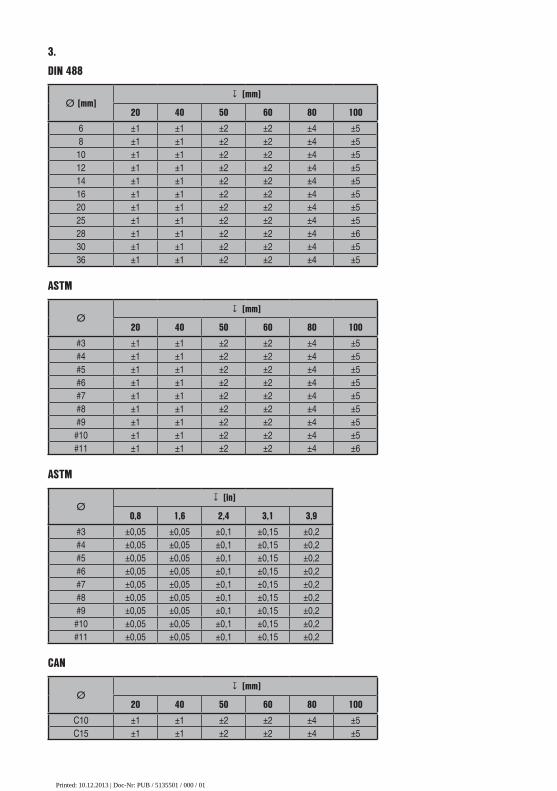
ASTM
Ø↧ [mm]
20 40 50 60 80 100#3 ±1 ±1 ±2 ±2 ±4 ±5#4 ±1 ±1 ±2 ±2 ±4 ±5#5 ±1 ±1 ±2 ±2 ±4 ±5#6 ±1 ±1 ±2 ±2 ±4 ±5#7 ±1 ±1 ±2 ±2 ±4 ±5#8 ±1 ±1 ±2 ±2 ±4 ±5#9 ±1 ±1 ±2 ±2 ±4 ±5#10 ±1 ±1 ±2 ±2 ±4 ±5#11 ±1 ±1 ±2 ±2 ±4 ±6
ASTM
Ø↧ [in]
0,8 1,6 2,4 3,1 3,9#3 ±0,05 ±0,05 ±0,1 ±0,15 ±0,2#4 ±0,05 ±0,05 ±0,1 ±0,15 ±0,2#5 ±0,05 ±0,05 ±0,1 ±0,15 ±0,2#6 ±0,05 ±0,05 ±0,1 ±0,15 ±0,2#7 ±0,05 ±0,05 ±0,1 ±0,15 ±0,2#8 ±0,05 ±0,05 ±0,1 ±0,15 ±0,2#9 ±0,05 ±0,05 ±0,1 ±0,15 ±0,2#10 ±0,05 ±0,05 ±0,1 ±0,15 ±0,2#11 ±0,05 ±0,05 ±0,1 ±0,15 ±0,2
CAN
Ø↧ [mm]
20 40 50 60 80 100C10 ±1 ±1 ±2 ±2 ±4 ±5C15 ±1 ±1 ±2 ±2 ±4 ±5
3. DIN 488
Ø [mm]↧ [mm]
20 40 50 60 80 1006 ±1 ±1 ±2 ±2 ±4 ±58 ±1 ±1 ±2 ±2 ±4 ±510 ±1 ±1 ±2 ±2 ±4 ±512 ±1 ±1 ±2 ±2 ±4 ±514 ±1 ±1 ±2 ±2 ±4 ±516 ±1 ±1 ±2 ±2 ±4 ±520 ±1 ±1 ±2 ±2 ±4 ±525 ±1 ±1 ±2 ±2 ±4 ±528 ±1 ±1 ±2 ±2 ±4 ±630 ±1 ±1 ±2 ±2 ±4 ±536 ±1 ±1 ±2 ±2 ±4 ±5
Printed: 10.12.2013 | Doc-Nr: PUB / 5135501 / 000 / 01
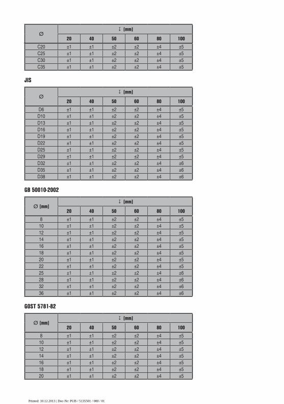
GB 50010-2002
Ø [mm]↧ [mm]
20 40 50 60 80 1008 ±1 ±1 ±2 ±2 ±4 ±510 ±1 ±1 ±2 ±2 ±4 ±512 ±1 ±1 ±2 ±2 ±4 ±514 ±1 ±1 ±2 ±2 ±4 ±516 ±1 ±1 ±2 ±2 ±4 ±518 ±1 ±1 ±2 ±2 ±4 ±520 ±1 ±1 ±2 ±2 ±4 ±522 ±1 ±1 ±2 ±2 ±4 ±525 ±1 ±1 ±2 ±2 ±4 ±628 ±1 ±1 ±2 ±2 ±4 ±632 ±1 ±1 ±2 ±2 ±4 ±636 ±1 ±1 ±2 ±2 ±4 ±6
JIS
Ø↧ [mm]
20 40 50 60 80 100D6 ±1 ±1 ±2 ±2 ±4 ±5D10 ±1 ±1 ±2 ±2 ±4 ±5D13 ±1 ±1 ±2 ±2 ±4 ±5D16 ±1 ±1 ±2 ±2 ±4 ±5D19 ±1 ±1 ±2 ±2 ±4 ±5D22 ±1 ±1 ±2 ±2 ±4 ±5D25 ±1 ±1 ±2 ±2 ±4 ±5D29 ±1 ±1 ±2 ±2 ±4 ±5D32 ±1 ±1 ±2 ±2 ±4 ±6D35 ±1 ±1 ±2 ±2 ±4 ±6D38 ±1 ±1 ±2 ±2 ±4 ±6
GOST 5781-82
Ø [mm]↧ [mm]
20 40 50 60 80 1008 ±1 ±1 ±2 ±2 ±4 ±510 ±1 ±1 ±2 ±2 ±4 ±512 ±1 ±1 ±2 ±2 ±4 ±514 ±1 ±1 ±2 ±2 ±4 ±516 ±1 ±1 ±2 ±2 ±4 ±518 ±1 ±1 ±2 ±2 ±4 ±520 ±1 ±1 ±2 ±2 ±4 ±5
C20 ±1 ±1 ±2 ±2 ±4 ±5C25 ±1 ±1 ±2 ±2 ±4 ±5C30 ±1 ±1 ±2 ±2 ±4 ±5C35 ±1 ±1 ±2 ±2 ±4 ±5
Ø↧ [mm]
20 40 50 60 80 100
Printed: 10.12.2013 | Doc-Nr: PUB / 5135501 / 000 / 01

4. DIN 488
Ø [mm]↧ [mm]
20 40 50 60 80 1006 ±2 ±2 ±2 ±3 ±4 ±58 ±2 ±2 ±2 ±3 ±4 ±510 ±2 ±2 ±2 ±3 ±4 ±512 ±2 ±2 ±2 ±3 ±4 ±514 ±2 ±2 ±2 ±3 ±4 ±516 ±2 ±2 ±2 ±3 ±4 ±520 ±2 ±2 ±2 ±3 ±4 ±525 ±2 ±2 ±2 ±3 ±4 ±528 ±2 ±2 ±2 ±3 ±4 ±530 ±2 ±2 ±2 ±3 ±4 ±536 ±2 ±2 ±2 ±3 ±4 ±5
BIS 1786:1985
Ø [mm]↧ [mm]
20 40 50 60 80 1006 ±1 ±1 ±2 ±2 ±4 ±58 ±1 ±1 ±2 ±2 ±4 ±510 ±1 ±1 ±2 ±2 ±4 ±512 ±1 ±1 ±2 ±2 ±4 ±516 ±1 ±1 ±2 ±2 ±4 ±520 ±1 ±1 ±2 ±2 ±4 ±525 ±1 ±1 ±2 ±2 ±4 ±528 ±1 ±1 ±2 ±2 ±4 ±532 ±1 ±1 ±2 ±2 ±4 ±5
ASTM
Ø ↧ [mm]
20 40 50 60 80 100#3 ±2 ±2 ±2 ±3 ±4 ±5#4 ±2 ±2 ±2 ±3 ±4 ±5#5 ±2 ±2 ±2 ±3 ±4 ±5#6 ±2 ±2 ±2 ±3 ±4 ±5#7 ±2 ±2 ±2 ±3 ±4 ±5#8 ±2 ±2 ±2 ±3 ±4 ±5
22 ±1 ±1 ±2 ±2 ±4 ±525 ±1 ±1 ±2 ±2 ±4 ±528 ±1 ±1 ±2 ±2 ±4 ±532 ±1 ±1 ±2 ±2 ±4 ±536 ±1 ±1 ±2 ±2 ±4 ±5
Ø [mm]↧ [mm]
20 40 50 60 80 100
Printed: 10.12.2013 | Doc-Nr: PUB / 5135501 / 000 / 01

JIS
Ø↧ [mm]
20 40 50 60 80 100D6 ±2 ±2 ±2 ±3 ±4 ±5D10 ±2 ±2 ±2 ±3 ±4 ±5D13 ±2 ±2 ±2 ±3 ±4 ±5D16 ±2 ±2 ±2 ±3 ±4 ±5D19 ±2 ±2 ±2 ±3 ±4 ±5D22 ±2 ±2 ±2 ±3 ±4 ±5D25 ±2 ±2 ±2 ±3 ±4 ±5D29 ±2 ±2 ±2 ±3 ±4 ±5D32 ±2 ±2 ±2 ±3 ±4 ±5D35 ±2 ±2 ±2 ±3 ±4 ±5D38 ±2 ±2 ±2 ±3 ±4 ±5
CAN
Ø ↧ [mm]
20 40 50 60 80 100C10 ±2 ±2 ±2 ±3 ±4 ±5C15 ±2 ±2 ±2 ±3 ±4 ±5C20 ±2 ±2 ±2 ±3 ±4 ±5C25 ±2 ±2 ±2 ±3 ±4 ±5C30 ±2 ±2 ±2 ±3 ±4 ±5C35 ±2 ±2 ±2 ±3 ±4 ±5
ASTM
Ø ↧ [in]
0,8 1,6 2,4 3,1 3,9#3 ±0,1 ±0,1 ±0,1 ±0,15 ±0,2#4 ±0,1 ±0,1 ±0,1 ±0,15 ±0,2#5 ±0,1 ±0,1 ±0,1 ±0,15 ±0,2#6 ±0,1 ±0,1 ±0,1 ±0,15 ±0,2#7 ±0,1 ±0,1 ±0,1 ±0,15 ±0,2#8 ±0,1 ±0,1 ±0,1 ±0,15 ±0,2#9 ±0,1 ±0,1 ±0,1 ±0,15 ±0,2#10 ±0,1 ±0,1 ±0,1 ±0,15 ±0,2#11 ±0,1 ±0,1 ±0,1 ±0,15 ±0,2
#9 ±2 ±2 ±2 ±3 ±4 ±5#10 ±2 ±2 ±2 ±3 ±4 ±5#11 ±2 ±2 ±2 ±3 ±4 ±5
Ø ↧ [mm]
20 40 50 60 80 100
Printed: 10.12.2013 | Doc-Nr: PUB / 5135501 / 000 / 01

BIS 1786:1985
Ø [mm]↧ [mm]
20 40 50 60 80 1006 ±2 ±2 ±2 ±3 ±4 ±58 ±2 ±2 ±2 ±3 ±4 ±510 ±2 ±2 ±2 ±3 ±4 ±512 ±2 ±2 ±2 ±3 ±4 ±516 ±2 ±2 ±2 ±3 ±4 ±520 ±2 ±2 ±2 ±3 ±4 ±525 ±2 ±2 ±2 ±3 ±4 ±528 ±2 ±2 ±2 ±3 ±4 ±532 ±2 ±2 ±2 ±3 ±4 ±5
GOST 5781-82
Ø [mm]↧ [mm]
20 40 50 60 80 1008 ±2 ±2 ±2 ±3 ±4 ±510 ±2 ±2 ±2 ±3 ±4 ±512 ±2 ±2 ±2 ±3 ±4 ±514 ±2 ±2 ±2 ±3 ±4 ±516 ±2 ±2 ±2 ±3 ±4 ±518 ±2 ±2 ±2 ±3 ±4 ±520 ±2 ±2 ±2 ±3 ±4 ±522 ±2 ±2 ±2 ±3 ±4 ±525 ±2 ±2 ±2 ±3 ±4 ±528 ±2 ±2 ±2 ±3 ±4 ±532 ±2 ±2 ±2 ±3 ±4 ±536 ±2 ±2 ±2 ±3 ±4 ±5
GB 50010-2002
Ø [mm]↧ [mm]
20 40 50 60 80 1008 ±2 ±2 ±2 ±3 ±4 ±510 ±2 ±2 ±2 ±3 ±4 ±512 ±2 ±2 ±2 ±3 ±4 ±514 ±2 ±2 ±2 ±3 ±4 ±516 ±2 ±2 ±2 ±3 ±4 ±518 ±2 ±2 ±2 ±3 ±4 ±520 ±2 ±2 ±2 ±3 ±4 ±522 ±2 ±2 ±2 ±3 ±4 ±525 ±2 ±2 ±2 ±3 ±4 ±528 ±2 ±2 ±2 ±3 ±4 ±532 ±2 ±2 ±2 ±3 ±4 ±536 ±2 ±2 ±2 ±3 ±4 ±5
Printed: 10.12.2013 | Doc-Nr: PUB / 5135501 / 000 / 01

*2037331*
2037
331
Hilti CorporationLI-9494 SchaanTel.: +423 / 234 21 11Fax: +423 / 234 29 65www.hilti.com
Hilti = registered trademark of Hilti Corp., Schaan W 4215 | 1013 | 00-Pos. 2 | 1 Printed in Germany © 2013Right of technical and programme changes reserved S. E. & O. 2037331 / A3
Printed: 10.12.2013 | Doc-Nr: PUB / 5135501 / 000 / 01
Related Documents