Synthesis and Characterization of Polyethylene Composites Based on Polysaccharide Islamabad A dissertation submitted to the Department of Chemistry, Quaid-i-Azam University, Islamabad, in partial fulfillment of the requirements for the degree of Doctor of Philosophy in Organic Chemistry by Sadullah Mir Department of Chemistry Quaid-i-Azam University Islamabad 2011

Welcome message from author
This document is posted to help you gain knowledge. Please leave a comment to let me know what you think about it! Share it to your friends and learn new things together.
Transcript

Synthesis and Characterization of Polyethylene Composites Based on
Polysaccharide
Islamabad
A dissertation submitted to the Department of Chemistry, Quaid-i-Azam University, Islamabad, in partial fulfillment
of the requirements for the degree of
Doctor of Philosophy
in
Organic Chemistry
by
Sadullah Mir
Department of Chemistry Quaid-i-Azam University
Islamabad 2011

DECLARATION
This is to certify that this dissertation entitled “Synthesis and Characterization of Polyethylene Composites Based on Polysaccharide” submitted by Mr. Sadullah Mir is accepted in its present form by the Department of Chemistry, Quaid-i-Azam University, Islamabad, Pakistan, as satisfying the partial requirement for the degree of Doctor of Philosophy in Organic Chemistry.
External Examiner(1): ___________________________________
External Examiner(2): ___________________________________
Supervisor: ___________________________________ Assoc. Prof. Dr. Mrs. Humaira Masood
Siddiqi Department of Chemistry Quaid-i-Azam University
Islamabad
Co-Supervisor: ___________________________________ Dr. Tariq Yasin
Principal Scientist Department of Metallurgy and Materials
Engineering PIEAS, Islamabad
Head of Section: ___________________________________ Assoc. Prof. Dr. Shahid Hameed
Department of Chemistry Quaid-i-Azam University
Islamabad
Chairman: ___________________________________ Prof. Dr. Saqib Ali
Department of Chemistry Quaid-i-Azam University
Islamabad

IN THE NAME OF ALLAH
THE COMPASSIONATE
THE MERCIFUL

Dedicated
to my family members, who are my inspiration in
everything I do and every choice I make

“Allah will exalt those who believe among you, and
those have knowledge to high ranks”
(Al-Quran)

Sayings of Holy Prophet (S.A.W.)
“If anybody goes on his way in search of knowledge,
Allah Almighty will make easy for him the way to
paradise”
(Sahih Muslim)

i
ACKNOWLEDGEMENTS
I owe my profound thanks and deepest sense of gratitude to Almighty ALLAH, Who
blessed me with fortitude, potential and capability to complete my Ph. D. work. I wish to
express fervent sense of thankfulness to my affectionate supervisor, Assoc. Prof. Dr.
Mrs. Humaira Masood Siddiqi, Department of Chemistry, Quaid-i-Azam University,
Islamabad, and my co-supervisor Dr Tariq Yasin (Principal Scientist), Pakistan
Institute of Engineering and Applied Sciences, Islamabad, for their wholehearted interest
and dedicated supervision. Their inspiring guidance, valuable suggestions, energizing
encouragement, generous help, good manners and friendly behavior made it possible for
me to accomplish this tough task.
I am highly indebted to pay my cordial gratitude to Prof. Peter Halley, Director, Center
of High Performance Polymer, School of Chemical Engineering University of
Queensland Australia, for his mammoth help, cooperation and for accommodating me in
his Lab, for almost one year. I also acknowledge the valuable discussion of Dr Timothy
Nicholson and Dr Gregory Cash of the same department. Many thanks are due to Mr.
Roger Cater (Manager) and Mr. Bob Taylor (PARTEC Institute and The Composite
Training Centre Brisbane) for providing me some necessary processing equipment for
my research work.
I am grateful to Prof. Dr. Saqib Ali, Chairman, Department of Chemistry, Quaid-i-Azam
University, Islamabad, for providing laboratory facilities during my research work. Prof.
Dr. N. H. Rama and Assoc. Prof. Dr. J. H. Zaidi from the same department are highly
acknowledged due to their friendly behavior, cheering attitude and fruitful discussions.
A special word of gratitude is due to Mr. Amir Badshah, Mr. Sher Wali khan, Mr.
Refaqat Ali Khan and Mr. Hafiz Zia-ur-Rehman, for their guidance, countless assistance
and nice company. I would like to express my deepest appreciation to all of my Lab
Fellows, who assisted me in one way or the other. I am greatly honored to mention the
nice cooperation of all employees of the department, especially Mr. Sharif Chohan and
Muhammad Ilyas.
Last but not least, no words to portray my feelings of admiration about my affectionate
parents, the prayers of whom enabled me to achieve this target. I am also grateful to my
brothers, Mr. Khan Amir (Businessman), Mr. Badshah Mir (Businessman), Mr. Abdullah
Mir (G. Manager NDC), Mr. Gul Amir (MSc Mathematics, Principal PAF Shaheen

ii
College, Peshawar), Mr. Taj Mir (M.A. Islamiat, Headmaster Junior School), Dr. Sher
Azam (Physicist), for their prayers, love and support.
Thanks to my wife Reena Gul, for her patience, and caring my son during my absence
from home for several years in connection with my studies. I have missed a lot my cute
son Samar Saad. I love you very much.
Countless thanks to Madam Naseem Salma Ali (Brisbane) and Hafiz M. Abrar
(Brisbane) and my nephews, Dr. Sohail Adnan (MBBS), and Mr. Zulfam Adnan
(Chemical Engineer), whose supplications enabled me to achieve what I longed for.
Many thanks are due to Higher Education Commission of Pakistan for financial support.
(Sadullah Mir Afridi)

iii
ABSTRACT
Some novel biodegradable polymer composites were synthesized, using polyolefin as a
matrix with various natural polymers including chitosan, starch and carboxymethyl
cellulose as biodegradable additives. The compatibility of the components was enhanced
with different silane coupling agents. The materials were heat mixed in brabender plasti-
corder mixer using roller rotor. During mixing, different temperatures were used to mix
and decompose the initiator to start the grafting of silane and crosslinking of the
polymer. The blended materials were hot pressed into sheets. The hydrolysis and the
condensation reactions of silane were carried out in hot water at 95°C for 20 hours. After
crosslinking reactions, the prepared sheets were dried in vacuum oven for 16 hours
before characterization.
The structural analysis of the non-crosslinked and crosslinked composites was carried
out using Fourier Transform Infrared (FTIR) and Scanning Electron Microscope (SEM)
techniques. The crosslinking reaction was confirmed by FTIR spectra, which revealed
the important absorption peaks of siloxane (Si-O-Si) and Si-O-C bonds. SEM images
also revealed that crosslinking has improved the dispersion and interaction between
polymer and the additives. The degree of crosslinking as determined by gel content
analysis was found to be directly proportional to the amount of chitosan in
HDPE/chitosan composite. In LLDPE/starch/sepiolite composite, it decreased with high
sepiolite loading. Thermogravimetric analysis showed higher thermal stability of the
crosslinked composites. Differential scanning calorimetry showed decreasing trend of
percentage crystallinity with increasing amount of additive. This behavior is associated
to the network structure and the disorder of close packing of polyethylene chains.
Rheological studies of crosslinked composites showed linear viscoelastic behavior with
high complex viscosities (*) and dynamic shear storage moduli (G`) reflecting a strong
interaction between matrix-filler interphase and the elastic nature of the crosslinked
samples. High tensile strength (TS) and reduced elongation at break (Eb) values were
observed in all the crosslinked samples of HDPE/chitosan and HDPE/carboxymethyl
cellulose composites. However, the TS and Eb values of non-crosslinked and crosslinked
formulations for LLDPE/starch/sepiolite composite showed decreasing trends with high
starch and sepiolite loading. Creep experiments indicated a small deformation in
crosslinked composites, which showed that silane effectively coupled the immiscible
components.

iv
ABBREVIATIONS
ASTM American society of testing and material
ATR-FTIR Attenuated total reflection fourier transform infrared spectroscopy
CMCs Ceramic matrix composites
CMC Carboxymethyl cellulose
DBTDL Dibutyltindilaurate
DCP Dicumyl peroxide
DS Degree of substitution
DSC Differential scanning calorimetry
EAA Ethylene acrylic acid
Eb Elongation at break
EDS Energy-dispersive X-ray spectroscopy
ESCR Environmental stress crack resistance
EVOH Ethylene vinyl alcohol
FTIR Fourier transform infrared spectroscopy
G` Shear storage modulus
G`` Shear loss modulus
HDPE High density polyethylene
∆Hf Heat of fusion
∆ Hf° Standard heat of fusion
LCB Long chain branching
LDPE Low density polyethylene
LLDPE Linear low density polyethylene
LDPE-g-DBM Low density polyethylene graft dibutyl maleate
LLDPE-g-MAH Linear low density polyethylene graft maleic anhydride
LMDPE Linear medium density polyethylene
MAH Maleic anhydride
MFI Melt flow index
MMCs Metal matrix composites
MPa Mega Pascal
MPE Maleated polyethylene
OBCS O-butyryl chitosan

v
PBSA Polybutylene succinate adipate
PBTA Polybutylene terephthalate adipate
PCL Polycaprolactone
PEG Polyethylene glycol
PEI Polyethylenimine
phr Part per hindered part of resin
PLLA Poly(L-lactic) acid
PMCs Polymer matrix composites
POE Polyoxyethylene
POSS Polyhedral oligomeric silsesquioxane
PVA Polyvinyl alcohol
rpm Rotation per minute
SCB Short chain branching
SiCs Silicon carbides
SEM Scanning electron microscopy
Tc Crystallization temperature
TGA Thermogravimetric analysis
Tm Melting temperature
TS Tensile strength
UV Ultra violet
VLDPE Very low density polyethylene
VTES Vinyltriethoxysilane
VTMS Vinyltrimethoxysilane
Xc Degree of crystallinity
* Complex viscosity

vi
LIST OF TABLES
Tables Title Page
1.1 ASTM grades of polyethylene 4
1.2 Structural arrangement of polysaccharides 11
1.3 Molecular configurations of polysaccharides 11
1.4 Silane used for natural polymer composite: chemical structures, organo functionalities and target polymer matrices
24
2.1 Structures of reagents for polyethylene composites 36
2.2 Formulations of HDPE/chitosan composites with 0.3 phr stearic acid 39
2.3 Formulations of LLDPE/starch/sepiolite composites with 0.3 phr stearic acid
40
2.4 Formulations of HDPE/CMC composites with 0.3 phr stearic acid 41
3.1.1 Gel content analysis of HDPE/chitosan composites 49
3.1.2 Percentage weight loss and weight residues of HDPE/chitosan composites
52
3.1.3 DSC analysis of HDPE/chitosan composites 53
3.1.4 Melt flow indices of non-crosslinked HDPE/chitosan composites 58
3.1.5 Tensile properties of HDPE/chitosan composites 59
3.2.1 Gel content analysis of LLDPE/starch/clay composites 67
3.2.2 Percentage weight loss and weight residue of LLDPE/starch/sepiolite composites
69
3.2.3 DSC analysis of LLDPE/starch/sepiolite composites 70
3.2.4 Tensile properties of LLDPE/starch/sepiolite composites 74
3.3.1 Percentage weight loss and weight residue of HDPE/CMC composites 80
3.3.2 DSC analysis of HDPE/CMC composites 81
3.3.3 Tensile properties of HDPE/CMC composites 85

vii
LIST OF FIGURES
Figures Title Page
1.1 General classification of composite materials 3
1.2 Schematic structures of different grades of polyethylene 5
1.3 Chitin and chitosan structures 12
1.4 Structure of linear amylase 15
1.5 Structure of branched amylopectin 15
1.6 Structure of cellulose 18
1.7 Crystalline structure of sepiolite 21
3.1.1 Particle size distribution of chitosan 48
3.1.2 FTIR spectra of HDPE/chitosan composites: virgin HP (a), HP30 (b), XHP30 (c)
48
3.1.3 TGA thermograms of HDPE/chitosan composites 50
3.1.4 Derivative curves of HDPE/chitosan composites 51
3.1.5 Time sweep analysis of HDPE/chitosan composites: HP30 (a) and XHP30 (b) at 150oC
54
3.1.6 Dynamic shear moduli (G`) and (G``) of non-crosslinked HDPE/chitosan composites at 150oC
55
3.1.7 Dynamic shear moduli (G`) and (G``) of crosslinked HDPE/chitosan composites at 150oC
56
3.1.8 Complex viscosities (η*) of HDPE/chitosan composites at 150oC 57
3.1.9 Creep analysis of non-crosslinked and crosslinked HDPE/chitosan composites at 60oC
60
3.1.10 Scanning electron micrographs of non-crosslinked HDPE/chitosan composite: HP30 (a) and HP50 (b, c)
61
3.1.11 Scanning electron micrographs of crosslinked HDPE/chitosan composite (XHP50) at different magnifications
62
3.1.12 EDS analysis of crosslinked HDPE/chitosan composite: XHP50 (a, b) 63
3.2.1 Particle size distribution of starch (a) and sepiolite (b) 66

viii
3.2.2 TGA thermograms of LLDPE/starch/sepiolite composites 68
3.2.3 Dynamic shear storage modulus (G`) of LLDPE/starch/sepiolite composites at 150oC
71
3.2.4 Dynamic shear loss modulus (G``) of LLDPE/starch/sepiolite composites at 150oC
72
3.2.5 Complex viscosity (η*) of LLDPE/starch/sepiolite composites at 150oC
72
3.2.6 Scanning electron micrographs of LLDPE/starch/sepiolite composite: LLS 4/30 (a, b) XLLS 4/30 (c)
75
3.3.1 Particle size distribution of carboxymethyl cellulose 77
3.3.2 FTIR spectra of HDPE/CMC composites 78
3.3.3 TGA thermograms of HDPE/CMC composites 79
3.3.4 Dynamic shear moduli (G`) and (G``) of non-crosslinked HDPE/CMC composites at 150oC
82
3.3.5 Dynamic shear moduli (G`) and (G``) of crosslinked HDPE/CMC composites at 150oC
83
3.3.6 Complex viscosities (η*) of HDPE/CMC composites at 150oC 84
3.3.7 Creep analysis of non-crosslinked and crosslinked HDPE/CMC composites at 60oC
86
3.3.8 Scanning electron micrographs of HDPE/CMC composites: HC30 (a) XHC30 (b)
87

ix
LIST OF SCHEMES
Schemes Title Page
1.1 Synthesis of cellulose acetate 19
1.2 Synthesis of carboxymethyl cellulose 20
1.3 Hydrolysis (a) and condensation (b) of silane coupling agent 23
1.4 Maleic anhydride grafting and condensation reaction in LDPE/starch composites
29
3.1 Reaction during processing: generation of free radicals from dicumyl
peroxide (a) abstraction of hydrogen from polyethylene chain (b)
crosslinking induced by free radicals (c) silane grafting reaction (d)
46
3.2 Reaction during crosslinking: hydrolysis (a) self condensation of
silane moieties (b) condensation of silanol with hydroxyl group of
chitosan (c) condensation of silanol with amino group of chitosan (d)
47
3.3 Reaction during crosslinking: hydrolysis (a) self condensation of
silanol moieties (b) condensation of silanol with hydroxyl group of
starch (c) condensation of silanol with hydroxyl group of sepiolite (d)
65
3.4 Reactions during crosslinking: hydrolysis (a) self condensation of
silanol moieties (b) condensation of silanol with OR group of
carboxymethyl cellulose (c)
76

x
PREFACE
In the present research work, some novel potentially biodegradable composites were
developed from biodegradable additives such as chitosan, starch and carboxymethyl
cellulose. The compatibility of the components was improved with organosilanes as
crosslinking agents. Crosslinkers have been used to improve not only the mechanical
properties but also the thermal properties. A brief outline of this thesis is given below:
Adhering to the main theme of the work, the first chapter gives a brief account about the
composites and their classification. Polyethylene is dealt with emphasizing the types,
manufacturing process and its applications. An overview to polysaccharides, their
classification, structure and applications are discussed in the subsequent section. A
concise introduction about clay mineral (sepiolite) and the silane coupling agent are also
highlighted in this chapter. Besides the introduction, this chapter also contains a detailed
review of the related literature. The scope and objective of this thesis is discussed at the
end of this chapter.
The second chapter describes the materials, characterization techniques and procedures
for the synthesized composites. The developed formulations and their codes are given in
the form of tables.
The third chapter comprises three sections. Each section is devoted to the following
biodegradable composite systems:
High density polyethylene/chitosan composite
Linear low density polyethylene/starch/sepiolite composite
High density polyethylene/carboxymethyl cellulose composite
The results obtained by the characterization of these composites are discussed in detail
and important results are highlighted and compared.
Finally, the work is concluded and recommendations for future plan are presented at the
end of third chapter. The references and the list of publications are given at the end of
this thesis

CONTENTS
Page
Acknowledgements i
Abstract iii
Abbreviations iv
List of Tables vi
List of Figures vii
List of Schemes ix
Preface x
Chapter-1 Introduction 1-33
1.1 Composite 1
1.2 Types of composites 1
1.2.1 Metal matrix composites (MMCs) 1
1.2.2 Ceramic matrix composites (CMCs) 2
1.2.3 Polymer matrix composites (PMCs) 2
1.3 Polyethylene 4
1.4 Classification of polyethylene 5
1.4.1 High density polyethylene (HDPE) 5
1.4.1.1 Manufacturing processes of high density polyethylene
6
1.4.1.2 Properties of high density polyethylene 6
1.4.1.3 Applications of high density polyethylene 6
1.4.2 Low density polyethylene (LDPE) 7
1.4.2.1 Manufacturing processes of low density polyethylene 7
1.4.2.2 Properties of low density polyethylene 7
1.4.2.3 Applications of low density polyethylene 7
1.4.3 Linear low density polyethylene (LLDPE) 8
1.4.3.1 Manufacturing processes of linear low density polyethylene
8

1.4.3.2 Properties of linear low density polyethylene 8
1.4.3.3 Applications of linear low density polyethylene 9
1.5 Polysaccharides 9
1.5.1 Classification and structure of polysaccharides 9
1.5.1.1 Chitin and chitosan 12
1.5.1.1.1 Applications of chitosan 13
1.5.1.2 Starch 14
1.5.1.2.1 Applications of starch 16
1.5.1.3 Cellulose and cellulose derivatives 17
1.5.1.3.1 Cellulose Acetate 18
1.5.1.3.2 Carboxymethyl cellulose 18
1.6 Clay minerals 20
1.6.1 Sepiolite 21
1.7 Compatibility 22
1.7.1 Silane coupling agents 22
1.7.2 Silane crosslinked polymer composites 23
1.7.3 Applications of silane coupling agents in advanced materials
24
1.8 Literature review 25
1.8.1 Chitosan composites with synthetic polymers 25
1.8.1.1 Chitosan composites with natural polymers 27
1.8.2 Starch/polyolefin composites 28
1.8.3 Cellulose-based composites 30
1.9 Scope and objective of thesis 32
Chapter-2 Experimental 34-44
2.1 Materials for composite preparation 34
2.1.1 High density polyethylene 34

2.1.2 Linear low density polyethylene 34
2.1.3 Chitosan 34
2.1.4 Starch 34
2.1.5 Sepiolite 34
2.1.6 Carboxymethyl cellulose 35
2.1.7 Coupling agents 35
2.1.8 Initiator 35
2.1.9 Dibutyltin dilaurate 35
2.1.10 Stearic acid 35
2.1.11 Solvents 35
2.2. General procedure for composite’s preparation 36
2.2.1 Procedure for the synthesis of HDPE/chitosan composites
37
2.2.2 Procedure for the synthesis of LLDPE/starch/sepiolite composites
38
2.2.3 Procedure for the synthesis of HDPE/CMC composites 38
2.3. Instruments/characterization techniques 41
2.3.1 Brabender plasti corder mixer 41
2.3.2 Hot press 41
2.3.3 Vacuum oven 41
2.3.4 Particle size analyzer 42
2.3.5 FTIR spectroscopy 42
2.3.6 Gel content analysis 42
2.3.7 Thermogravimetric analysis (TGA) 42
2.3.8 Differential scanning calorimetry (DSC) 42
2.3.9 Melt rheology 43
2.3.10 Melt flow index (MFI) 43

2.3.11 Tensile properties 43
2.3.12 Short term creep test 43
2.3.13 Scanning electron microscopy (SEM) 44
Chapter-3 Results and Discussion 45-87
3.1 High density polyethylene/chitosan composites 45
3.1.1 Mechanism of silane crosslinking in HDPE/chitosan composites
45
3.1.2 Particle size distribution of chitosan 47
3.1.3 FTIR analysis of HDPE/chitosan composites 48
3.1.4 Gel content analysis of HDPE/chitosan composites 49
3.1.5 Thermogravimetric analysis of HDPE/chitosan composites
49
3.1.6 Differential scanning calorimetry of HDPE/chitosan composites
52
3.1.7 Melt rheology of HDPE/chitosan composites 53
3.1.8 Melt flow index of HDPE/chitosan composites 58
3.1.9 Tensile properties of HDPE/chitosan composites 58
3.1.10 Short term creep test of HDPE/chitosan composites 59
3.1.11 Scanning electron microscopy of HDPE/chitosan composites 60
3.2 Linear low density polyethylene/starch/sepiolite composites 64
3.2.1 Mechanism of silane crosslinking in LLDPE/starch/sepiolite composites
64
3.2.2 Particle size distribution of starch and sepiolite 66
3.2.3 Gel content analysis of LLDPE/starch/sepiolite composites
67
3.2.4 Thermogravimetric analysis of LLDPE/starch/sepiolite composites
67
3.2.5 Differential scanning calorimetry of LLDPE/starch/sepiolite composites
69
3.2.6 Melt rheology of LLDPE/starch/sepiolite composites 70

3.2.7 Tensile properties of LLDPE/starch/sepiolite composites 73
3.2.8 Scanning electron microscopy of LLDPE/starch/sepiolite composites
74
3.3 High density polyethylene/carboxymethyl cellulose composites 76
3.3.1 Mechanism of silane crosslinking in HDPE/CMC composites 76
3.3.2 Particle size distribution of CMC 77
3.3.3 FTIR analysis of HDPE/CMC composites 78
3.3.4 Thermogravimetric analysis of HDPE/CMC composites 79
3.3.5 Differential scanning calorimetry of HDPE/CMC composites
80
3.3.6 Melt rheology of HDPE/CMC composites 81
3.3.7 Tensile properties of HDPE/CMC composites 84
3.3.8 Short term creep test of HDPE/CMC composites 85
3.3.9 Scanning electron microscopy of HDPE/CMC composites
86
Conclusions 88
Future plan of work 89
References 90-115
List of Publications 116

1
Chapter – 1
INTRODUCTION
1.1 Composite
There is a truth about the statement that technological development depends on advances
in the field of materials. Whatever the field may be, the final limitation on the
advancement depends on materials. Composite materials represent nothing but a giant
step in the ever-constant endeavor of optimization in materials. The basic engineering
materials such as metals, ceramics and polymers have been used for a variety of
applications in daily life. They have outstanding properties but certain limitations as
well. They cannot be used in advanced applications such as space craft, aircrafts,
automobiles, electronic, marine, high temperature reactors, and medical industries [1].
These advanced technologies require high performance materials. In order to meet such
requirements, composite materials have been designed whose properties can be
optimized for specific demands.
A composite material can be defined as “a combination of two or more
chemically distinct phases separated by an interface” [2]. The resulting composite has
unique combination of properties quite different from its constituents. In other words, the
constituents work together and retain their properties in bulk form [3]. Composite
material consists of the matrix phase that is in greater proportion and reinforcing phase
that is present in small quantity. The reinforcement added to the matrix not only reduces
its cost but also enhances its thermal and mechanical properties. The general
classification of composite material is shown in Figure 1.1.
1.2 Types of composites
There are three main types of composite materials depending on the nature of the
“matrix”.
(1) Metal matrix composites
(2) Ceramic matrix composites
(3) Polymer matrix composites 1.2.1 Metal matrix composites (MMCs)
In metal matrix composites, the metals or the metallic alloys are used as matrix
(continuous phase) and the reinforcement is generally non-metals or ceramics. Ceramics

2
are used in the form of particulate whiskers or fibers such as titanium carbides (TiCs),
silicon carbides (SiCs) and alumina particles [4-5]. Carbon fiber is used in magnesium
metal matrix composite only [6]. These metal matrix composites have many advantages
over monolithic metals, which include better thermal properties, higher specific strength,
high specific modulus, higher wear resistance and lower coefficient of thermal expansion
[7].
Copper-based MMCs are used in aerospace applications, which have been
reinforced by carbon fibers or SiC fibers [8-9]. Aluminum-based matrices are reinforced
either by SiC or alumina fibers [10]. The MMCs have certain superior mechanical
properties in comparison with most polymer composites, i.e., higher transverse strength
and stiffness, greater shear and compressive strength and better high-temperature
capabilities. Some important advantages of MMCs are non-flammability, high thermal
and electrical conductivities and resistance to most radiations [11-12]. Due to above-
mentioned properties, the MMCs are used in machinery, electronics, aviation and house-
hold products. The MMC materials are not used widely because of high manufacturing
cost, low reliability and greater fluctuation in their mechanical strength [13].
1.2.2 Ceramic matrix composites (CMCs)
The word ceramic is derived from the Greek word “Keramos” which is the name of a
suburb in Athens [14]. The term covers the inorganic non-metallic materials such as
alumina, zirconia, carbides and borides [15]. The CMCs include a great variety of
materials, e.g., polycrystalline ceramics and glass which are reinforced by particles,
flakes and fibers [16]. The matrix and the reinforcement have high-temperature
properties. Ceramic matrix composites are fabricated by various techniques which
include reinforcement with powder matrix followed by heat pressing, vapor deposition
and techniques involving slurries. Common fabrication techniques involve high
temperature during processing [17]. It is, therefore, necessary that both matrix and
reinforcement should be thermally stable. Monolithic ceramics such as alumina, silicon
nitrides, glasses and carbon have high strength and stiffness but are brittle [18]. These
monolithic ceramics are thermally stable and maintain their unique properties at high
temperature [19].
1.2.3 Polymer matrix composites (PMCs)
The commonly-used matrix for composites is polymeric in nature and constitutes 90%
of all composites. There are two types of polymer matrices used in PMCs, i.e.,

3
thermoset or thermoplastic. Polyolefin is an important class of thermoplastic polymers
and has been used as matrix in PMCs since long. Some important types of polyolefins
are high density polyethylene (HDPE), low density polyethylene (LDPE) and linear low
density polyethylene (LLDPE).
Figure 1.1 General classification of composite materials
Composite
Reinforcement Matrix
Particulate composite
Laminate composite
Fibrous composite
Non-biodegradable Clay mineral Biodegradable
Polymer matrix Ceramic matrix Metal matrix
Thermoplastic Thermosetting
Polyethylene Polyamide Polyurethane Polysulfone Polystyrene
HDPE LDPE LLDPE
Glass fiber
Polymer fiber
Carbon fiber

4
The polymeric composites are formed either by particle or by fiber reinforcement
[20]. The polymeric composites have low working temperature, high coefficient of
thermal expansion, sensitivity to radiation and moisture [21]. The water absorption from
environment may have serious effect on mechanical performance, which includes
swelling and lowering of glass transition temperature (Tg) [22]. On the other side,
carbon fiber reinforced polymers have very low coefficient of thermal expansion and
epoxy matrices are radiation resistant. PMCs are used in various fields like food
packaging, automobiles, aerospace, boats, electronic and medical appliances [23-27].
1.3 Polyethylene
Polyethylene is a semi-crystalline polymer that is used extensively due to its unique
combination of properties, cost and ease of fabrication. Polyethylene was first
accidentally produced by Kirk and Othmer in 1933 under extremely high pressure [28].
The first HDPE was produced in 1950’s with the discovery of metal catalysis by Phillips
Petroleum (USA) and the Max Plank institute (Germany) that enabled the production at
low pressure [29]. In 1970’s, Union Carbide developed a low pressure LLDPE [30].
Polyethylene is available with a wide array of engineering properties to provide
toughness, chemical abrasion and impact resistance, low coefficient of friction,
durability in the elements and near-zero moisture absorption. These properties make
polyethylene an ideal material for many applications. On the other hand, polyethylene is
not degradable polymer under normal environmental conditions [31]. It takes a long
time for complete degradation. It is this reason that it ends up in landfills and oceans,
which is a great environmental issue.
Previously polyethylene was classified on the basis of the type of manufacturing
processes that is either high pressure or low pressure polyethylene. American standard of
testing material (ASTM) has classified polyethylene into grades based on density as
shown in Table 1.1.
Table 1.1 ASTM grades of polyethylene [32]
Grade Density g/cm3
Low Density 0.910-0.925
Linear Low Density 0.926-0.940
High Density 0.941-0.959

5
The very low density polyethylene (VLDPE) was introduced by Kurtz, which has a
density less than 0.91 g/cm3 [33]. Recently, classification based on structure has been
used. Figure 1.2 shows the structural differences between various grades of polyethylene.
LDPE HDPE LLDPE
Figure 1.2 Schematic structures of different grades of polyethylene [34]
LDPE is characterized frequently by long chain branching (LCB) and short chain
branching (SCB). LLDPE has no LCB but some SCB, whereas HDPE has neither LCB
nor SCB [35].
1.4 Classification of polyethylene
There are three important types of polyethylene (PE) based on density and structure.
(1) High density polyethylene
(2) Low density polyethylene
(3) Linear low density polyethylene
1.4.1 High density polyethylene (HDPE)
HDPE was discovered long before LDPE [36, 37]. It is generally inert and nontoxic and
is widely used in food packaging, surgery and prosthetic devices [38, 39]. Commercial
HDPE is a predominantly linear polymer and contains crystalline and amorphous phases
[40]. Its homopolymer is normally 94% crystalline and if branching is added to the linear
polymer, its density is lowered and crystallinity is dissipated [41]. HDPE is the most
widely used type of PE having density ranging from 0.941 to 0.959 g/cm3 and has wide
range of applications [42].

6
1.4.1.1 Manufacturing processes of high density polyethylene
The manufacturing of HDPE is divided into four main processes; namely, solution phase
process, slurry process, modified high pressure process and gas phase process.
The solution phase process can be operated either by medium pressure or by high
pressure. Recently, this process is further improved and is still in production [43]. In
slurry process, hydrocarbon liquid is deliberately chosen as bad solvent for PE while
keeping the temperature low. It uses loop reactors with light or heavy diluents stirred
tank or liquid pool reactors [44]. This process gives wide melt flow indices and limited
density ranges. The modified high pressure processes is utilized infrequently due to its
limited range of densities and melt flow indices [45]. The gas phase process was first
introduced by Union Carbide in 1970 [46]. It uses fluidized reactors, which enable it to
achieve product versatility. Uniform fluidization is achieved by ethylene flow and rapid
circulation is needed to remove heat.
1.4.1.2 Properties of high density polyethylene
HDPE exhibits low chemical reactivity. It is stable to salt, alkaline solutions and does not
react with organic acids [47]. The permeability of HDPE to water and inorganic bases is
also very low. HDPE is thermally stable polymer. Low molecular weight HDPE is brittle
and breaks at low strain without neck development [48]. Exposure of molded HDPE
article to sun light and air results in color change, brittleness and cracks, etc [49].
1.4.1.3 Applications of high density polyethylene
HDPE pipes are used in low pressure applications such as transporting water and gas
[50]. In injection molding, HDPE is injected into mold at 200ºC and 70-140 MPa [51].
Its applications include cups, toys, house wares, etc. The largest single use of HDPE is
blow molded articles. It is widely used for food packaging, oil and fuel tanks, etc. HDPE
is stiff, impermeable and has higher softening temperature, which is useful for film
applications [52]. Shopping bags are made from the rolled hollow HDPE film. HDPE has
excellent moisture resistance and other electrical properties. It is, therefore, used in wire,
cable encapsulation, communication, power and control [53]. HDPE is used to coat the
inside of the mold uniformly during rotational molding operation for large storage tanks,
etc.

7
1.4.2 Low density polyethylene (LDPE)
The first grade polyethylene was produced by Imperial Chemical Industries (ICI) in 1933
from free radical polymerization using a high pressure process [54]. LDPE has a short
and long branched chains with amorphous structure. The amorphous structure and weak
intermolecular forces tend to reduce its density and tensile strength [55]. LDPE has
density ranging from 0.910-0.925 g/cm3 [56].
1.4.2.1 Manufacturing processes of low density polyethylene
LDPE is manufactured under high pressure (81-276 MPa) and high temperature (130-
330 oC) via free radical initiator, such as peroxide or oxygen [57]. The polymerization
process is based on free radical reactions which lead to formation of long chain structure
[58]. The short chain branches also exist in LDPE, which consist of 1, 3-diethyl and 2-
ethylhexyl side chains.
The polymerization process for the production of LDPE is carried out in tubular
or stirred autoclave reactor [59]. In these reactors, the control of molecular weight can be
accomplished by reaction pressure, temperature or the addition of chain transfer agent
[60]. The LDPE resins made from the tubular and autoclave differ from each other; the
main difference is in the type and level of long chain branching. The autoclave reactor
gives rise to shorter and long chain branching than the tubular reactor [61]. This is due to
higher level of back mixing in each stage of the reactor.
1.4.2.2 Properties of low density polyethylene
LDPE can continuously withstand up to temperature of 80oC to 95oC for a short time.
The tensile strength (TS) of LDPE is lower due to weak intermolecular forces, reduced
crystallinity and low density. It has lower TS and high ductility [55]. It has unique and
desirable flow properties due to its high branching and long chain structures. LDPE
shows higher resistance to dilute and concentrated acids, bases and other organic
compounds, however, it has poor resistance against halogenated hydrocarbons [62].
1.4.2.3 Applications of low density polyethylene
LDPE is widely used for manufacturing of various containers, plastic bags, tubing and
molded laboratory equipments [63]. In extrusion coating, the LDPE is used as a thin
coating on materials like aluminum foil and paper board. The injection molded products
of LDPE include lids, buckets and toys, etc. LDPE is also used in blow molding, but
compared to HDPE, it is less used for this purpose. LDPE is used in applications where

8
clarity, flexibility and up-to-the-mark environmental stress-crack resistance (ESCR) are
required [64].
1.4.3 Linear low density polyethylene (LLDPE)
Union Carbide and Dow chemical first commercialized LLDPE in the late 1970s. The
annual global production of LLDPE is approximately 13.6 million tons [65]. In the early
1990s, the LLDPE industry was revitalized with the introduction of several new product
families, including novel single-site-catalyzed very low density polyethylene (VLDPE)
called plastomers [66], super-hexene LLDPE, and metallocene-catalyzed (mLLDPE) for
commodity applications [67]. Work continues by resin companies around the world on
new classes of LLDPE for a variety of applications. The difference between LLDPE and
LDPE is that the former has narrow molecular weight distribution and does not contain
long chain branching. LLDPE is a linear polymer having short branches made by
copolymerization of ethylene with alpha olefins (e.g. 1-butene, 1-hexene and 1-octene).
It is generally represented by formula [−CH2−CH2−CH2−CH−(Cn-2H2(n-2) +1)], where n
represents the number of carbon atoms. Generally, LLDPE resins do not contain long
chain branches; however, some of its resins may contain some long chain branches such
as VLDPE [68].
1.4.3.1 Manufacturing processes of linear low density polyethylene
LLDPE can be produced by using manufacturing process as discussed in section 1.4.1.1
for HDPE processing at low pressure. These processes include solution phase process,
slurry process and gas phase process.
1.4.3.2 Properties of linear low density polyethylene
Conventional LLDPE covers the density range of 0.926–0.940 [69]. It has higher impact,
tensile strength and puncture resistance than LDPE [55]. LLDPE is a saturated
hydrocarbon and is generally unreactive [55]. The most reactive parts of the polymer
molecule are tertiary carbons at short-chain branch points and double bonds at chain
ends. LLDPE is stable in alcohols, alkaline solutions, and saline solutions [70]. It is not
attacked by weak organic or inorganic acids. It has heterogeneous composition and
higher density fraction with minimal branching and form spherulitic structure [71]. The
amount of crystallinity in LLDPE increases by decreasing α-olefins co-monomer
contents and it becomes stiffer by increasing its crystallinity [71].

9
1.4.3.3 Applications of linear low density polyethylene
LLDPE is used in packaging especially for film, bags and sheets. Injection molding is
the second largest product area for LLDPE [72]. Its applications include food containers,
trash cans and lids, etc. Pipe and tubing are extruded from LLDPE at limited seal with
higher burst strength [73]. LLDPE is also used in the insulation of wires and cable for
low and medium voltage applications. The ESCR and improved flexibility make it ideal
for blow molded bottle applications. Its rotational molded articles are used for storage
tank and outdoor furniture.
1.5 Polysaccharides
Polysaccharides are naturally available polymers where monosaccharides are linked by
glycosidic linkage. These are commonly used as food stuff and have applications in food,
healthcare, agriculture, biotechnology and synthesis of biomaterials [74-76].
Polysaccharides are being increasingly explored to be utilized in biomaterial
development. The characteristic structural and functional properties of polysaccharides
are appropriate for synthesizing useful biomaterials for many applications. The presence
of a number of hydroxyl, amino and amide groups on polysaccharides give them specific
functions and provide easy attachment to other functional groups. Hydroxyl groups can
be modulated to give specific biological identifications or alter the physical and chemical
properties of already existing molecules. Water-soluble polysaccharides are appropriate
to synthesize hydrogels, which can be used in drug delivery and in drug formulations
[77]. Polysaccharides are easily degraded in the environment and their degradation
products are nontoxic. A wide range of polysaccharide applications include food
additives, bioseparation, bioencapsulation, biosensors, wound care and other implantable
devices [78-83].
1.5.1 Classification and structure of polysaccharides
There are different ways to classify polysaccharides. On the basis of source,
polysaccharides can be classified into following four groups [84]:
1. Plant-derived polysaccharides.
2. Marine polysaccharides including both animal and algal polysaccharide.
3. Extra-cellular matrix polysaccharides (ECM) present in mammals.
4. Polysaccharides derived from microbes (microbial polysaccharides).
One particular polysaccharide can be synthesized by more than one organism.
Important examples include: alginates synthesized by both algal and bacterial species

10
and cellulose, which can be obtained from both plants and bacteria. Gums are plant
polysaccharides, which can be acquired from plant seeds and from tree barks as
inundates. Gums have different applications in food and pharmaceutical formulations
[85].
Polysaccharides are produced by the enzymatic condensation of
monosaccharides. Monosaccharides are of different types but majority of
polysaccharides consist of no more than three different monosaccharides.
Polysaccharides exist in two configurations, i.e., linear or branched [86]. A polymer
with two different monosaccharides have variable pattern of arrangement, whereas three
component polysaccharides may have more varied structural arrangements and
complexity as shown in Table 1.2.
Free monosaccharide units contain four or five hydroxyl groups, each capable of
forming glycosidic linkages. In most cases single hydroxyl group has two optical
isomers. Therefore, the possible number of configurations, in which two different
monosaccharides can be linked, may exceed 40, although enzymatic synthesis limits this
variety of configurations. Due to this reason, polysaccharides are found in a variety of
configurations. These include rigid rod, flexible coil, random coil and globular forms
(Table 1.3).
Chain configurations determine physical properties of polysaccharides, i.e., free
hydroxyl groups of polysaccharides form the basis of polysaccharide solubility or
insolubility in different solvents. The presence of polar hydroxyl groups and other
ionizable components in polysaccharides make them water loving. Some
polysaccharides have intricate structures and assume crystalline shape which makes them
water insoluble. Polysaccharides like cellulose, starch and chitin can be made water
soluble by modifying their primary hydroxyl groups. Most polysaccharides are involved
in mediating biological events across the cell to cytoplasm and in intracellular matrix
[87]. This is the main reason why scientists are interested to develop target specific drug
carriers from oligo or polysaccharides [88]. These specific structural and functional
characteristics of polysaccharides develop researchers’ interest to synthesize biomaterials
with specific therapeutic and non-therapeutic effects.

11
Table 1.2 Structural arrangements of polysaccharides [84].
S. No. Arrangements Shape
1 Linear
2 Alternating repeat
3 Interrupted repeat
4 Block copolymer
5 Branched
6 Complex repeat
Table 1.3 Molecular configurations of polysaccharides [84]
S. No. Configurations Shape
1 Rigid rod
2 Semi-flexible coil
3 Random coil
4 Globular, highly branched

12
1.5.1.1 Chitin and chitosan
Chitin and chitosan are second important members of polysaccharide group after
cellulose. Chitin is poly-β-(1, 4)-linked 2-acetamido-2-deoxy-D-glucopyranose. It is one
of the most abundant and renewable biopolymer after cellulose [89]. It can be easily
obtained from crustacean animals and fungi etc. Chitosan is structural analog of
cellulose. Chitosan is poly-β-(1, 4)-linked 2-deoxy-2-amino-D-glucopyranose, which is
the deacetylated product of chitin. In 1830, it was isolated from insects and this material
was named chitin. Rouget discovered chitosan in 1859, and later on, much fundamental
research has been carried out on this compound [90]. Henri Braconnot extracted chitin
from mushrooms in 1881 while he was working in the botanical gardens at the Academy
of Sciences in Nancy, France [91]. In crustacean animals, their shells mainly consist of
30-40% protein and fat, 30-50% calcium carbonate and calcium phosphate and 15-25%
chitin. The molecular structures of chitin and chitosan are shown in Figure 1.3. The
present global annual production of chitin and chitosan is estimated to be in the range of
3000–10,000 metric tons [92]. Both chitin and chitosan are nontoxic, biocompatible, and
biodegradable and possess chemical side groups for modification and attachment to other
molecules [93]. Chitosan is mainly used as thickening and gelling agent [95, 96], fruit
coatings and preservatives [96, 97]. Chitosan is also a useful substrate for modification
of other molecules, due to the presence of easily modifiable amino and hydroxyl groups
[98].
n
O
C H 2 O H
N H C O C H 3
O H
H
H
H
H
O
C H 2 O H
N H C O C H 3
O H
H
H
H
O
C H 2 O H
N H 2
O H
H
H
H
O
C H 2 O H
N H C O C H 3
O H
H
H
H
O O O O
H
H
H
HH
H
n
O
C H 2 O H
N H 2
O H
H
H
H
H
O
C H 2 O H
N H 2
O H
H
H
H
O
C H 2 O H
N H C O C H 3
O H
H
H
H
O
C H 2 O H
N H 2
O H
H
H
H
O O O O
H
H
H
HH
H
C H I T I N
C H I T O S A N
Figure 1.3 Chitin and chitosan structures [99].

13
Recent research is revealing the benefits of chitosan in food formulations where it plays
several important roles, including cholesterol reduction and fat-binding capacity [100]. It
is used as a drug delivery vehicle for the nasal administration of morphine and act as
ligand for gene delivery [101].
1.5.1.1.1 Applications of chitosan
Chitosan molecules have the ability to bind with toxic heavy metals, amino acids and fats
[102]. Unlike cellulose, chitosan possesses positive ionic charges by which it can
chemically bind with negatively charged fats, lipids, cholesterol, proteins and
macromolecules. Chitosan has also potential uses in many nutrition as well as food
processing industries. The molecular weight and degree of deacetylation are the two
most important properties of chitosan, which determine the potential uses of chitosan in
different fields [103]. The major areas of applications of chitosan are discussed below:
Chitosan has found uses in many healthcare applications. Chitosan has two
hydroxyl groups and one amino group in its repeating pyranose ring. The chemical
modifications of these groups give rise to various novel properties. It can be used as
antibacterial agent, anticoagulant, anti-thrombogenic and haemostatic material [104,
105]. The most essential medical applications of chitosan are as wound healing
promoting dressings, dermatological agents, and biodegradable carriers for slow release
of drugs [106, 107].
Chitosan has a number of health benefits like ability to promote the growth of
some types of bacteria in the intestine that help against diseases. It has attracted much
attention as a biomedical material due to its unique biological activities such as
antitumor, antiulcer, immunostimulatory and antibacterial [108, 109]. Many people take
dietary supplements made from chitosan to improve their skin, hair and nail health [110,
111]
Chitosan and its degraded products are nontoxic and non-allergenic so the body
would not reject them as foreign invaders, thus, they can be used in production of
emulsifiers, antistatic agents to extend the shelf life of cosmetic products [112]. It
possesses fungicidal and fungi static properties. Chitosan is the only natural cationic
polymer that becomes viscous by neutralizing with acid. These materials are then used in
creams, lotions and permanent waving lotions and several derivatives such as nail
lacquers [113].

14
Nowadays the uses of biologically-active and environmental-friendly substances
are much effective in modern agriculture system [114]. People become more conscious
about using toxic chemicals on plants and they need to use certain environmental-
friendly plant protecting substances that do not accumulate in soil, plants, animals and
human body and can easily be degraded in natural environment. Such substances have
also the ability to increase plant stability against diseases.
Chitosan is a biopolymer having all these properties. Chitosan possesses a high
growth stimulating efficiency combined with antifungal and antibacterial activity [115].
Chitosan inhibits the reproduction of pathogens and also induces activation of genes,
which produces protease inhibitors that protect against insect attack. It also stimulates
the plant hormones responsible for root formation, stem growth, fruit formation and
development [116].
Chitosan coating has shown significant delayed fruit and vegetable spoilage such
as tomatoes, bananas and strawberries at different temperatures. The low molecular
weight chitosan has a greater inhibitory effect against phytopathogens than the high
molecular weight chitosan [117]
Chitosan was first used industrially in 1975 for wastewater treatment [118].
Chitosan as a polymer has a natural tendency to form long chain of molecules with
positive charges that act like clarifiers and gather organic materials such as oils,
perspiration, cosmetics, detergents and other contaminants suspended in water [119]. The
materials then coagulate to form flakes that can easily filter out.
Chitosan and its oligomers are used as color removing-agents in textile effluents.
Chitosan has a unique molecular structure due to which it has high affinity for many
classes of dyes like disperse, direct, reactive, acid, vat, sulfur and naphthol dyes [120].
The cost of chitosan-based clarifiers is comparable to that synthesized from petroleum
based polymers which are less effective. The chitosan clarifiers are much more effective
because these do not introduce additional chemicals into the water. The toxicity level of
this natural polymer is about equal to table sugar. They are environmentally safe and
harmless to plants, humans, fish and other animals.
1.5.1.2 Starch
Starch is a product of a large number of glucose units linked by α-1,4 glycosidic bonds.
Starch is an important energy source for all green plants. Starch constitutes an important

15
component of human diet and is found in foods like potatoes, wheat, maize, rice and
cassava. Pure starch is white, odorless and tasteless powder. Starch powder is insoluble
in cold water and alcohol [121]. It exists in two structural forms, i.e., linear and branched
(Figure 1.4 and Figure 1.5).
O
CH2OH
OH
OH
O
O
CH2OH
OH
OH
O
O
CH2OH
OH
OH
O
O
CH2OH
OH
OH
OH
H H
H
H
H H
H
H
H H H
H
H
HHHH
H
H
n
α-1,4 glycosidic bond
Figure 1.4 Structure of linear amylose [122]
O
CH2OH
OH
OH
O
O
CH2OH
OH
OH
O
O
OH
OH
O
O
CH2OH
OH
OH
OH
H H
H
H
H H
H
H
H H H
H
H
HHHH
H
H
n
CH2
OCH2OH
OH
O
OH
H
H
HH
H
Figure 1.5 Structure of branched amylopectin [122]
The linear component is termed as amylose. Amylose is low molecular weight polymer
with average molecular weight being one and a half million. It makes up one fourth the
weight of starch. The most abundant polysaccharide component is amylopectin
α-1,6 glycosidic bonds

16
consisting of D-glucose with α-1,4 glycosidic bond. Amylopectin has branched chains
which occur through α-1,6 linkages at about 1 chain in every straight chain of 25 D-
glucose units. Amylopectin has average molecular weight up to 10 million. Starch is
water soluble polymer because of numerous hydroxyl groups. The highly branched
characters of amylopectin interferes with its precipitation in solution, however, at low
temperature the water binding capacity decreases and amylopectin molecules aggregate
and precipitate forming gel solution [123]. Due to the difference in structure, amylose
and amylopctin properties differ from each other. Amylose forms strong flexible films
used as coating agent [124]. On the other hand, amylopectin acts as a good thickening
agent and has usage in food and paper industry [125].
1.5.1.2.1 Applications of starch
Starch has a broad range of applications both in the food and non-food sectors. Some
important applications of starch are mentioned below:
Starch serves the purpose of thickening when used as additive in foods such as
custards, sauces, soups, puddings, gravies, pie fillings and salad dressing. Corn starch
has a high amylose contents and is used to obtain crisp in fried snack products [126].
High maltose content favors moisture retention and color control in syrups [127]. High
fructose starch-based syrup is used to replace sugar in soft drink beverages. Starch
products control moisture, texture and also replace sucrose in soft confections such as ice
cream [128]. Starch is also used as a binder in pharmaceutical industry [129].
Starch is used on a large scale in paper making. In copy paper, starch content may
be as high as 8%. Both unmodified and chemically-modified starches are used in paper
making [130]. Starch polymer carries a positive charge during the paper making process.
These cationic starch derivatives bind with the negatively charged paper fibers/cellulose
and inorganic fillers [131]. Cationic starch provides strength to the paper during wet
synthetic process termed as wet strength. Starch-based solution is used to rewet the paper
web in the dry end of the paper making process. This process is called surface sizing.
Starch-based solutions are applied to the paper web by means of various mechanical
processes. Cationic starch moieties bind and provide strength to the paper web [132].
Starch glues are made up of unmodified starch and additives such as caustic soda
and borax [133]. This glue is a strong adhesive for corrugated board production. Starch is
also used in the construction industry to make rigid gypsum wall boards. Starch is used

17
in various adhesives for book binding, wall paper adhesives, gummed paper, paper sack
production, tube winding, bottle labeling and envelope adhesives [133].
Clothing starch (laundry starch) can be mixed in water to prepare liquid that is
used on the laundering of clothes. Starch was used in Europe in the 16th and 17th
centuries to stiffen the wide colors made up of fine linen [134]. Starch derivatives are
used in the synthesis of textile chemicals that reduce breakage of yarns during weaving
[135]. Starch is also used in printing industry to manufacture anti-set-off spray powder.
The powder separates printed sheets of paper and avoids wet ink from being set off
[136].
1.5.1.3 Cellulose and cellulose derivatives
Cellulose is a polymer of glucose with β-1,4 glycosidic linkages as shown in Figure 1.6.
It is present in plant cell walls and forms rigid cell support. Cellulose is also synthesized
by certain bacteria commonly by Aceto bacter xylinum [137]. Depending on the source
of its production, the average molecular weight of cellulose varies from 100,000 to
2,000,000. Cellulose has a linear configuration and abundant intramolecular and
intermolecular hydrogen bonding, which explains its mechanical strength and insoluble
nature. Thus high molecular weight cellulose is crystalline and insoluble in water and
organic solvents. Cellulose can be used to achieve homeostasis and as wound dressings
[138]. Hydroxyl groups of cellulose make H-bonding with body proteins [139]. Proteins
of blood coagulation pathways and complement system get activated when cellulose
binds to them.
The stable and crystalline cellulose needs to be modified for medical
applications. Cellulose can be easily degraded by enzymes when its structure is
modified by oxidation [140]. Natural cellulose is inert and stable and cannot be
degraded by mammals because they lack the enzymes required for this purpose.
Carboxymethyl cellulose, on the other hand, is more hydrophilic and non-crystalline
derivative of cellulose [141] and is, therefore, subjected to degradation by poorly-defined
hydrolytic reactions. Products derived from cellulose have diverse applications. Its
important derivatives are cellulose acetate, methyl cellulose, carboxymethyl cellulose,
etc.

18
n
O
CH2OH
OH
OH
H
H
H
H
O
CH2OH
OH
OH
H
H
H
O
CH2OH
OH
OH
H
H
H
O
CH2OH
OH
OH
H
H
H
O O O O
H
H
H
HH
H
Figure 1.6 Structure of cellulose [142].
1.5.1.3.1 Cellulose Acetate
Acetylation of cellulose fibers with acetic anhydride in the presence of sulfuric acid
produces cellulose acetate [143] as depicted in scheme 1.1. The product of this reaction
can be converted to lower degrees of acetate substitutes by partial deacetylation. Acetate
moieties are not water loving but dissolve in acetone. Membranes of cellulose acetate
have lower protein and water-binding capacity and therefore have decreased swelling in
aqueous medium, compared to parent cellulose fibers. This forms the basis for use of
cellulose acetate membranes in hemodialysis. Cellulose acetate has abundant surface H-
bonding with water, which lowers its protein-binding capacity. Cellulose acetate
membranes are more conventionally being used as dialysis membranes to filter
impurities from blood [144].
1.5.1.3.2 Carboxymethyl cellulose
Carboxymethyl cellulose (CMC) is synthesized when cellulose fibers are hydrated in
sodium hydroxide and then reacting this solution with monochloroacetic acid [145]. The
synthesis of CMC can be seen in scheme 1.2. Substitution of ionized groups alters
cellulose structure such that carboxymethyl cellulose becomes water soluble [146]. CMC
polymers form high viscosity solutions [147]. CMC can be used to synthesize
biomaterials because of its water soluble nature. For example, CMC has been combined
with hyaluronic acid forming hydrogel membranes which prevent adhesion formation
between viscera and abdominal wall after surgery [148]. Animal hepatocytes are
encapsulated in CMC-Chitosan complex which can be used for microbiological culture
and implantation [149]. CMC is used in food science as a viscosity modifier [150].
Many non-food products, such as toothpastes, laxatives, diet pills, water-based paints and
detergents contain CMC. In the oil drilling industry, CMC is used as an ingredient of
drilling mud, where it acts as a viscosity modifier and water retention agent. It can also

19
be used in ice packs to form a eutectic mixture resulting in a lower freezing point and,
therefore, more cooling capacity than ice.
n
O
CH2OH
OH
OH
H
H
H
H
O
CH2OH
OH
OH
H
H
H
O
CH2OH
OH
OH
H
H
H
O
CH2OH
OH
OH
H
H
H
O O O O
H
H
H
HH
H
Cellulose Ice bath Acetic anhydride/H2SO4
Hydrolysis CH3COOH + H2O
Cellulose acetate
n
O
CH2OAc
OAc
OSO3H
H
HH
H
O
CH2OAc
OAc
OSO3H
H
HH
O
CH2OAc
OAc
OSO3H
H
HH
O
CH2OAc
OAc
OSO3H
H
HH
O O O O
H
H
H
HH
H
n
O
CH2OAc
OAc
OH
H
HH
H
O
CH2OAc
OAc
OH
H
HH
O
CH2OAc
OAc
OH
H
HH
O
CH2OAc
OAc
OH
H
HH
O O O O
H
H
H
HH
H
Scheme 1.1 Synthesis of cellulose acetate [143].

20
n
O
CH2OH
OH
OH
H
H
H
H
O
CH2OH
OH
OH
H
H
H
O
CH2OH
OH
OH
H
H
H
O
CH2OH
OH
OH
H
H
H
O O O O
H
H
H
HH
H
Cellulose
Carboxymethyle cellulose
n
O
CH2OR
OR
OR
H
HH
H
O
CH2OR
OR
OR
H
HH
O
CH2OR
OR
OR
H
HH
O
CH2OR
OR
OR
H
HH
O O O O
H
H
H
HH
H
NaOH ClCH2CO2H
R= CH2CO2H
Scheme 1.2 Synthesis of carboxymethyl cellulose [145].
1.6 Clay minerals
The clay can be defined as naturally-occurring material composed of fine grained
minerals which become plastic at an appropriate water content and harden when dried
[151]. Clay minerals or hydrated phyllosilicates are fine grained fractions of rocks,
sediments or soils. For the most important clay-polymer composite applications, four
main classes of natural phyllosilicates used can be distinguished: [152] (i) The fibrous
clays (sepiolites and palygorskites) (ii) The kaolins, (iii) The bentonites (commercial
name of smectites) (iv) The common clays, which are more often interstratified clay
minerals.

21
1.6.1 Sepiolite
Sepiolite is a hydrated magnesium silicate with the half unit-cell formula:
Si12O30Mg8(OH)4.(H2O)4.8H2O [153]. The sepiolite structure is constituted by a
magnesium octahedral sheet in-between two layers of silica tetrahedrons which extend as
a continuous layer with an inversion of the apical ends every six units. This inversion
produces a discontinuous octahedral sheet which allows for the formation of rectangular
section, tunnel like pores, parallel to the fibre axis as shown in Figure 1.7 [154, 155].
Figure 1.7 Crystalline structure of sepiolite [153].
Geological deposits of sepiolite minerals are very limited around the world and most of
the world production comes from deposits of sedimentary origin located in Spain [156].
Sepiolite is used as a technical and industrial additive for a wide variety of sectors and
processes [157]. Its remarkable sorptive and rheological properties provide solutions for
applications ranging from rheological additives for industrial paints, processing aids,
binding additives [158-162], etc. but a very new application is also to be mentioned: the
use as nano-fillers in polymer systems [163].
Sepiolite is potentially well suited for the design of hybrid nanocomposites
because of its interesting needle-like morphology. Owing to the great number of active
centers on its surface (silanol groups and Mg2+ coordinated water), sepiolite induces a
high potential interaction level between both nanofillers/nanofillers and nanofillers/matrix
components. Moreover, although sepiolite is naturally hydrophilic, additional chemical
treatments may be carried out to give organophilicity or reactivity to its surface [164]. The
chemical modification is generally done by grafting with organosilanes [165].

22
1.7 Compatibility
The main disadvantage of thermoplastic composites based on polysaccharides is the
compatibility of hydrophobic and hydrophilic components, which results in poor
adhesion between the interfaces [166]. The weak interaction between the matrix-filler
interphase has lower load transferring ability from matrix to the reinforcement phase
[167]. A number of coupling agents have been used to enhance the adhesion between the
matrix-filler interphase. These coupling agents provide a strong chemical bonding at the
interface between polymer and filler [168]. This property of coupling agents can be used
to alter mode of failure of composites, so that failure does not happen at the interface.
These coupling agents have also been used to improve the thermal and mechanical
properties of polyolefin-based composites [169]. The most commonly-used coupling
agents in polyolefin composite are maleic acid and maleic anhydride. These have been
used for the compatibility of starch and polyolefin blends [170, 171]. Similarly, Rosales
et al studied the increased compatibility of magnesium hydroxide (Mg(OH)2) with low
density polyethylene (LDPE) using dibutyl maleate [172]. Ethylene acrylic acid (EAA)
has also been used as a compatibilizer for LDPE/starch blend [173]. Besides the above-
mentioned coupling agents, isocyanate has also been used as a coupling agent in natural
polymer reinforced polyurethane composite [174, 175].
1.7.1 Silane coupling agents
Silane coupling agents have been frequently used to enhance thermal and mechanical
properties of the composite materials. Silane coupling agents contain silicon, which is
capable of forming chemical association between dissimilar substances. These agents
usually associate organic polymer and inorganic additives [176]. A silane coupling agent
has hydrolysable organic functional groups. The general structure of a coupling agent is
X3SiR. Where X is a hydrolysable group that may be chloro, alkoxy and amino groups.
The organo R group can have a variety of functionalities such as NH2, OH, and vinyl
group which are chosen to meet the requirements of the polymer. Generally, coupling
agents with three X groups are used in composite materials because of their greater
stability on surfaces, but there are clearly other applications where it may be desirable to
use one or two hydrolysable X groups [176]. The choice of coupling agent for a
particular composite material also depends on the type of surface and polymer used
[176]. For this purpose, organic functional groups of coupling agent should match with
the polymer and adequately bind to it. Initial process in the application of a coupling

23
agent involves hydrolysis of its X group. Water is required in this reaction and end
products are HCl or alcohol [177, 178]. Acid or base may be used as a catalyst for the
hydrolysis. Hydrolysis is followed by condensation reaction between silane and other
surface reactive groups [179]. A schematic representation of hydrolysis and condensation
reaction of silane coupling agent is shown in scheme 1.3.
Si
OR
RO OR
SiHO OH
SiHO OHSi
OH
HO OH
Si
OH
HO OH
Catalyst
3 H2O+
2
H2O+O
a)
b)
R= CH3, C2H5
(DBTDL)
+ 3 ROH
Scheme 1.3 Hydrolysis (a) and condensation (b) of silane coupling agent [179].
1.7.2 Silane crosslinked polymer composites
Silanes are recognized as efficient coupling agents extensively used in composites and
adhesive formulations [180]. They have been successfully applied in inorganic filler
reinforced polymer composites such as glass fiber reinforced polymer composites [181,
182] and mineral filled polymer composites [183, 184]. Silanes are also used as adhesion
promoters in many adhesive formulations or as substrate primers, which provide stronger
adhesion [185]. The multi-functional structures of silanes have also been of interest in
applying them for natural fiber/polymer composites, since both glass fibers and natural
fibers bear reactive groups, and extensive research has accordingly been carried out to
screen the varied silane structures for natural fiber reinforced thermoplastic composites.
The most reported silanes and their applied target polymer matrices are listed in Table
1.4. With regard to these silanes shown in Table 1.4, aminosilanes, especially
aminopropyl(triethoxy)silane (APS), is most extensively reported in the literature as
coupling agent between natural fibers and thermoplastics or thermosets. Vinyl-silanes

24
and acryl-silanes are coupling agents that are able to establish covalent bonds with
polymeric matrices in the presence of peroxide initiators. Methacrylate–functional
silanes can display high levels of reactivity with unsaturated polyester matrices [186]
whilst azidosilanes can efficiently couple inorganic fillers with thermoplastic matrices
[187, 188]. However, there have been few reports of their use in natural fiber reinforced
thermoplastic composites.
Table 1.4 Silanes used for natural polymer composite: chemical structures, organo
functionalities and target polymer matrices [179].
Structures Function-alities
Matrices References
(RO)3Si-(CH)2-NH2 Amino Epoxy
Polyethylene
Butyl rubber
Polyacrylate
PVC
[186, 189-192]
(RO)3Si-CH=CH2 Vinyl Polypropylene
Polyethylene
Polyacrylate
[186, 193-197]
(RO)3Si-(CH3) OOC(CH)-C=CH2 Methacryl Polyethylene
Polyester
[186, 198-200]
(RO)3Si-(CH3) -SH Mercapto Natural rubber
PVC
[199, 201-203]
Glycidoxy
Epoxy
Butyl rubber
Polysulfide
[189, 190, 204, 205]
R2-Si-Cl2 Chlorine PVC
Polyethylene
[192, 206]
Vinyl triethoxy silane grafted plastic
Vinyl Polypropylene
Polyethylene
[197, 207]
(RO)3Si-(CH2)15-CH3 Alkyl Polyethylene
Natural rubber
[199, 208, 209]
R= CH3 or C2H5
1.7.3 Applications of silane coupling agents in advanced materials
Silane coupling agents are quite valuable to produce organic/inorganic hybrid materials
[176]. Nanomaterials made from different core structures can be made functional with
silane coupling agents [210]. Bridged polysilsesquioxanes are materials that have an

25
organic moiety between two silane groups. This is then easily crosslinked in inorganic
matrix. These materials can be used in sensors, catalysts, optics and coatings [211, 212].
Silane coupling agents can yield a variety of materials with desired properties, i.e., silane
based building blocks combined with other transition metals form a basic set of
nanomaterials whose applications are still emerging [213]. Silane crosslinked
polyethylene has been used in wire and cable production [214]. Silane crosslinking has
also been used to prepare wood thermoplastic composite [215], which is an alternative
material for plastic products. Polyhedral oligomeric silsesquioxane (POSS) was used as a
coupling agent in organic polymers. The presence of POSS in the polymer changes the
glass transition temperature, mechanical properties and heat resistance [216, 217].
1.8 Literature review [218]
A detailed review of the previous research related to the work accomplished in this study
will be discussed in this section. At the end of this section, the scope and objective of this
thesis as well as recommendation for further work is given in future plan.
1.8.1 Chitosan composites with synthetic polymers
As discussed previously, chitosan is a partially deacetylated derivative of chitin, a
cellulose-like polymer present in fungal cell walls and exoskeleton of arthropods, crabs,
lobster, shrimps, etc. It is a nontoxic, biodegradable and biocompatible polymer [219].
Chitosan has been often blended with other synthetic polymers, such as hydroxypropyl
cellulose, polyvinyl alcohol, and polyethylene oxide to obtain a material with sufficient
mechanical strength from which films and fibers have been prepared [220].
Chitosan was first blended with polyolefin by Ratajska et al [221]. In this work,
biodegradation tests were carried out in soil and water. The effect of microorganism
action on the samples was estimated by the loss of mass, water sorption capacity and
electron microscope studies. Generally, the results obtained lead to the conclusion that
biodegradability of polymer films depends considerably on the dimensions of the natural
component and their distribution in the film. Films containing large and weakly
dispersed particles prove to be more sensitive to biodegradation. Chun and his co-
workers have grafted O-butyryl chitosan (OBCS) to PE film by radiation grafting
technique [222]. The grafted films were characterized by Attenuated Total Reflection
Fourier Transform Infrared Spectroscopy (ATR-FTIR), Electron Spectroscopy for
Chemical Analysis (ESCA) and the water contact angle measurements. The blood
compatibility of the OBCS-grafted PE films was evaluated by Platelet Rich Plasma

26
(PRP) contacting experiments and protein adsorption experiments. These results suggest
that the developed photocrosslinkable chitosan has the potential of serving in blood-
contacting applications in medical use. Dufresne et al have explored blends of chitosan
with polyamide via the solution casting technique using formic acid as a common solvent
[223]. The morphology and the mechanical behavior of films with chitosan
concentrations ranging from 15% to 70% (w/w) were investigated by scanning electron
microscopy and dynamic mechanical analysis. The mechanical behaviour of the
materials was predicted from various models involving the percolation concept. From
comparison between experimental and predicted data, it was concluded that the chitosan
phase tends to sediment and to form a continuous phase on the lower face of the film, if
the chitosan content is high enough. This continuous phase is bristling with chitosan
domain cones, which can emerge on the upper face of the film depending on the blend
composition.
Srinivasaa et al have prepared chitosan/polyvinyl alcohol (PVA) blend [224].
They have found that the moisture content increased with increase in PVA concentration.
The moisture sorption data were used to fit eight sorption models and constants were
determined by linear fitting. These models were applicable for a wide range of water
activity. Fernandez et al have reported for the first time about the formulation,
morphology, water barrier and the antimicrobial activity of high and low molecular
weight chitosonium-acetate based solvent-cast blends with ethylene–vinyl alcohol
(EVOH) copolymers [225]. The blends based on the low molecular weight chitosan
grade showed enhanced phase morphology, transparency, water barrier properties and up
to 86% water permeability reduction compared to pure chitosonium-acetate films, as well
as excellent antimicrobial activity.
When the fraction of low molecular weight chitosan exceeded the phase inversion
in the blend, phase segregation became noticeable but good interfacial adhesion was still
observed. On the other hand, the blends with the high molecular weight chitosan were
translucent, even when this component was in the dispersed phase, and exhibited clearly
separated phase morphology but also showed antimicrobial properties. In both cases, the
release from the blends of protonated glucosamine groups (so-called active species)
correlated well with the antimicrobial phenomenology of the developed materials. This
study also showed that EVOH copolymers can also be made antimicrobial by a water
sorption-induced release mechanism, if acetic acid is incorporated into the polymer

27
formulation before casting from solution. Correlo et al have melt blended chitosan with
polycaprolactone (PCL), poly(butylene succinate) (PBS), poly(lactic acid) (PLA),
poly(butylene terephthalate adipate) (PBTA), and poly(butylene succinate adipate)
(PBSA) [226]. Additions of chitosan to PBSA tend to depress the melting temperature of
the polyester. The crystallinity and tensile strength of the polyesters containing 50%
chitosan also decreased. Similarly, blends of chitosan with PCL, PBTA, or PBSA
displayed fibrous appearances at the fractured surface due to the stretching of the
polymer threads. Increasing the amount of chitosan in the blends also reduced the
ductility of the fractured surface. The chitosan phases agglomerated into spherical
domains and the orientation of the polyesters (PCL, PBSA) does not seem to be affected
by the addition of chitosan.
1.8.1.1 Chitosan composites with natural polymers
Ming Shih et al have reported that cellulose/chitosan blend films have better tensile
properties and the addition of chitosan to the films results in slight antibacterial
properties [227]. Similarly, Zhai et al have prepared starch/chitosan blend films by
irradiation of compression-molded starch-based mixture in physical gel state with
electron beam (EB) at room temperature [228]. They have found that the tensile strength
and the flexibility of starch film were improved largely after incorporation of 20%
chitosan into starch film. X-ray diffraction and scanning electron microscope analysis of
starch/chitosan films indicated that there was interaction and microphase separation
between starch and chitosan molecules. Furthermore, in order to produce a kind of
antibacterial films, the starch/chitosan blend was irradiated, and its antibacterial activity
against Escherichia coli (E. coli) was measured via optical density method. After
irradiation, there was no obvious change in the structure of starch/chitosan blends, but
antibacterial activity was induced even when the content of chitosan was only 5% due to
the degradation of chitosan in blend under the action of irradiation.
Cheng and his co workers prepared blends of poly (l-lactic acid) (PLLA) and
chitosan with different compositions by precipitating PLLA/chitosan from acetic
acid/dimethylsulfoxide (DMSO) mixtures with acetone [229]. It was found that
intermolecular hydrogen bonds existed between two components in the blends, and the
hydrogen bonds were present mainly between carbonyls of PLLA and amino groups of
chitosan. The melting temperatures, crystallization temperatures and crystallinity of the
PLLA component decreased with the increase in chitosan content. Blending chitosan

28
with PLLA suppressed the crystallization of the PLLA component. Although the crystal
structure of PLLA component was not changed, the crystallization of the blends was
affected because of the existence of hydrogen bonds between two compounds.
1.8.2 Starch/polyolefin composites
At first, starch was adopted as filler for polyolefin by Griffin [230] and its concentration
was as low as 6–15%. Several researchers have conducted blending of neat polyethylene
and starch [231-242]. Basically, PE/starch blend has remarkably low physical properties.
The tensile strength of starch-filled LDPE reduced gradually as the percentage of starch
in the system increased, whereas percentage elongation at break reduced drastically with
a mere incorporation of 10 weight percent of starch in neat PE samples [234]. When
physical loads were applied to starch-filled PE film, lack of adhesion between starch and
LDPE caused unequal distribution of loading forces. Subsequently, physicomechanical
properties of LDPE/starch declined as weak starch particles were being “pulled-off”
from LDPE matrix [234]. One of the foremost approaches to improve compatibility of
LDPE and starch was through maleated blending methods [170, 243-247]. The easiest
approach was to introduce maleate group into starch-filled LDPE system, which was
through the addition of maleated polyethylene (MPE). Maleic anhydride (MAH) is
grafted to the backbone of polyethylene to induce polarity and subsequently to increase
compatibility with starch. In the meantime, in situ MAH grafting and condensation
reactions [248] (scheme 1.4) could also promote inter-phase adhesion in LDPE/starch.
However, it was noted that when MPE was added to LDPE, the tensile strength and
strain were slightly decreased [170]. This indicated that maleate compatibilizer did not
act as reinforcing agent to polymer but tended to deteriorate the mechanical properties.
On the other hand, when it was added to blending system with high starch loading, it
acted as adhesion enhancer between starch and LDPE blends. In a similar research work,
Yoo et al [170] also found that upon adding compatibilizer to linear low density
polyethylene (LLDPE)/starch blending, the breaking strengths were obviously increased
at 40 weight per cent of starch blending.

29
OOO
Polyethylene
Maleic anhydride
OH OOHO
OHO
OHO
O
O
HO OH
OH
n
n n
n
O O
OHO
O
O
HO OH
n
n
Starch
(b)
(a)
+ Starch
- H2O
Scheme 1.4 Maleic anhydride grafting and condensation reaction in LDPE/starch
composites [248]
Bakiaris et al [245] reported that MPE brought significant improvement up to 30 weight
per cent dosage. Beyond this optimum level, no remarkable effects could be noticed. At
this point, it was clear that adding excess MPE would not improve starch/polymer
system further but rather deteriorate the system. It has been reported that addition of
MPE helped to increase elongation at break for LDPE blends containing about 30 to 40
weight per cent of starch [170, 245-249]. On the other hand, excessive starch loading
could cause LLDPE to lose its continuity typically in chain re-orientation during cooling
period. Furthermore, plasma treatment to LDPE prior to MAH grafting reaction was able
to further improve adhesion strength of resulting compatibilizer [250]. Instead of
utilising on-shelf MPE, compatibilizing effect could also be induced during processing

30
by reactive extrusion method in single screw extruder. Wang et al [246] prepared linear
low density polyethylene graft maleic anhydride (LLDPE-g-MAH) by using LLDPE,
MAH and dicumyl peroxide. Girija and Sailaja [247] prepared low density polyethylene
graft dibutyl maleate (LDPE-g-DBM) and blended with starch. DBM has lower toxicity
to human life as well as low corrosion to equipment as compared to MAH. Addition of 6
to 12 weight per cent of LDPE-g-DBM resulted in optimal mechanical properties
(relative to LDPE). However, excess amount of LDPE-g-DBM also caused reduction in
mechanical properties due to accumulation of compatibilizer in separate phase. The
system behaved like a ternary blend which consisted of starch, LDPE and LDPE-g-DBM
phases. It can be assumed that addition of compatibilizer to produce better mechanical
properties was induced by crystallization of LDPE/starch blend. In fact, incorporation of
LDPE-g-DBM has decreased the degree of crystallization from 29.9-20.3% after
addition of 6 weight per cent of LDPE-g-DBM into 20 weight per cent of starch-filled
LDPE [247]. Chandra and Rustgi [243] stated that LLDPE-g-MAH had lower melting
point because the bulky MAH groups disturbed the crystallization structure and
eventually led to higher extent of super-cooling with lower crystallization temperature.
Thus, it was clear that compatibilizer would only help to rebuild integrity in different
polarities of LDPE/starch blend. Bikiaris et al. [173, 251] and Shogren et al [252] used
ethylene acrylic acid (EAA) as a compatibilizer for LDPE/starch blend. Starch–EAA–PE
composite was made by at least four different phases, e.g., starch, PE, EAA and an
“interpenetrated” phase component. The LDPE phase appeared to be immiscible with
EAA/starch complex which formed sheet like domain [253]. As reported by Otey and
Westhoff [254] in biodegradable starch-based blown film invention, that EAA copolymer
had carboxyl functionality which was compatible with starch in preparing disclosed film.
Substitution of high amount of EAA caused tensile strength to decrease from 24.61 to
12.69 MPa and simultaneously elongation dropped from 80-10%.
1.8.3 Cellulose-based composites
Synthetic polymers are particularly non-biodegradable in the soil and the incorporation
of cellulose derivatives will enhance their biodegradability. Rapid microbial degradation
of the cellulose component will in turn generate a network of voids in the polymer
matrix, weakening its structure and causing brittleness, which will protect the
environment from its waste. For the development of biocomposites for packaging
applications, Tajeddin et al studied the possibility of using cellulose in the production of
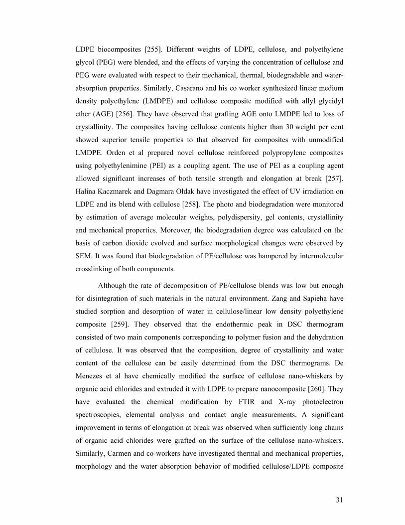
31
LDPE biocomposites [255]. Different weights of LDPE, cellulose, and polyethylene
glycol (PEG) were blended, and the effects of varying the concentration of cellulose and
PEG were evaluated with respect to their mechanical, thermal, biodegradable and water-
absorption properties. Similarly, Casarano and his co worker synthesized linear medium
density polyethylene (LMDPE) and cellulose composite modified with allyl glycidyl
ether (AGE) [256]. They have observed that grafting AGE onto LMDPE led to loss of
crystallinity. The composites having cellulose contents higher than 30 weight per cent
showed superior tensile properties to that observed for composites with unmodified
LMDPE. Orden et al prepared novel cellulose reinforced polypropylene composites
using polyethylenimine (PEI) as a coupling agent. The use of PEI as a coupling agent
allowed significant increases of both tensile strength and elongation at break [257].
Halina Kaczmarek and Dagmara Ołdak have investigated the effect of UV irradiation on
LDPE and its blend with cellulose [258]. The photo and biodegradation were monitored
by estimation of average molecular weights, polydispersity, gel contents, crystallinity
and mechanical properties. Moreover, the biodegradation degree was calculated on the
basis of carbon dioxide evolved and surface morphological changes were observed by
SEM. It was found that biodegradation of PE/cellulose was hampered by intermolecular
crosslinking of both components.
Although the rate of decomposition of PE/cellulose blends was low but enough
for disintegration of such materials in the natural environment. Zang and Sapieha have
studied sorption and desorption of water in cellulose/linear low density polyethylene
composite [259]. They observed that the endothermic peak in DSC thermogram
consisted of two main components corresponding to polymer fusion and the dehydration
of cellulose. It was observed that the composition, degree of crystallinity and water
content of the cellulose can be easily determined from the DSC thermograms. De
Menezes et al have chemically modified the surface of cellulose nano-whiskers by
organic acid chlorides and extruded it with LDPE to prepare nanocomposite [260]. They
have evaluated the chemical modification by FTIR and X-ray photoelectron
spectroscopies, elemental analysis and contact angle measurements. A significant
improvement in terms of elongation at break was observed when sufficiently long chains
of organic acid chlorides were grafted on the surface of the cellulose nano-whiskers.
Similarly, Carmen and co-workers have investigated thermal and mechanical properties,
morphology and the water absorption behavior of modified cellulose/LDPE composite

32
[261]. The chemical modification of the cellulose fibers with fatty acids clearly improved
the interfacial adhesion with the matrix and hence the mechanical properties of the
composites. The performance of the composites was strongly affected by the degree of
substitution (DS) and the fatty acid chain length as indicated by the fact that esterified
cellulose fibers with low DS gave composites with better mechanical properties.
1.9 Scope and objective of thesis
The main focus of this research was to develop environment-friendly polyethylene
composite based on polysaccharides. The composites, thus, formed are potentially
degradable, thanks to the presence of the natural polymers, which reduces pollution
generated by non-degradable polymer waste. Consequently, it has a positive effect both
on environment and economy.
From the above-cited literature survey, it has become evident that chitosan can be
used in polyolefins. Thus, high density polyethylene was selected as a matrix in this
study as it has been used extensively in a variety of disposable applications, owing to its
unique combination of properties, cost and ease of fabrication. It is non-biodegradable
polymer and very stable under normal environmental conditions. In the literature, it has
been shown that chitosan derivative was grafted to the polyethylene chain using ionizing
radiations. But in this work, the silane coupling agents are used as compatibilizer. In
addition to it, the silane crosslinked and non-crosslinked HDPE/chitosan composites are
extensively characterized. Thus, for the first time, the structural, thermal, rheological,
morphological and short term creep analyses of HDPE/chitosan composites are
thoroughly investigated.
From the previous work, it has been observed that starch blended with
polyethylene was studied in depth. A variety of coupling agents was used to enhance the
compatibility and mechanical properties of polyethylene/starch composites. In the preset
work, a clay mineral (sepiolite) is used to prepare linear low density
polyethylene/starch/sepiolite ternary blend. Sepiolite has been used to prepare polymer
nanocomposites, which have improved thermal and mechanical properties. It is also
observed that by incorporating sepiolite in polyethylene/starch composite, the thermal
properties are improved. In addition to sepiolite, silane coupling agents are used to
improve the compatibility of these composites. A large number of non-crosslinked as
well as crosslinked formulations are prepared and characterized.

33
Similarly, the preparation and characterization of silane crosslinked and non-
crosslinked high density polyethylene/carboxymethyl cellulose composite are also
reported for the first time in this study. Carboxymethyl cellulose (CMC) is a water-
soluble derivative of cellulose, therefore, blending CMC with polyethylene will produce
a material which can be easily biodegraded.
It is also an important aspect of this work that the composites produced by
peroxide melt blending of the components were characterized by multiple techniques
such as Thermoravimetric Analysis (TGA), Differential Scanning Calorimetry (DSC),
Gel Content Analysis, Dynamic Thermal Mechanical Analysis (DTMA), Fourier
Transform Infrared (FTIR) Spectroscopy, Scanning Electron Microscopy (SEM), Melt
Rheology and Tensile Testing.

34
Chapter – 2
EXPERIMENTAL
In this chapter, the materials used for the composite preparation along with synthetic
procedure and experimental details of the characterization techniques will be discussed.
The non-crosslinked and crosslinked composite compositions and codes are shown in
tabulated form.
2.1 Materials for composite preparation
2.1.1 High density polyethylene
High density polyethylene (HDPE) is commercially available as white pellets. It is
typically used for injection molded products. The melting temperature of HDPE is 123°C
with melt flow index of 2.2 g/10 min (190°C/2.16 kg). HDPE was purchased from Sigma
Aldrich, Australia.
2.1.2 Linear low density polyethylene
Linear low density polyethylene (LLDPE) is commercially available as white pellets. Its
melting temperature is 116°C having melt flow index of 1 g/10 min (190°C/2.16 kg). It
was purchased from Mitsui, Japan.
2.1.3 Chitosan
The degree of deacetylation of chitosan is greater than 75% and is extracted from crab
shells. It was purchased from Sigma Aldrich, Australia. Chitosan is available both in
powder and flakes, but in this study, chitosan flakes were cryo-ground into fine powder
before extrusion. Chitosan is soluble in 1 M aqueous acetic acid solution. Its bulk density
ranges from 0.15-0.3 g/cm3.
2.1.4 Starch
Gelose 80 is an unmodified high amylose starch containing approximately 80% amylose.
It is available as white powder. It was obtained from Penford, Australia.
2.1.5 Sepiolite
Sepiolite is a magnesium silicate having molecular formula
Si12O30Mg8(OH)4.(H2O)4.8H20. Sepiolite is commercially available and has needle shape
structure. It has light gray or light yellow color. Sepiolite was provided by the University
of Queensland, Australia.

35
2.1.6 Carboxymethyl cellulose
Carboxymethyl cellulose is commercially available as white granules. Its average
molecular weight is 90000 g/mol and melting temperature is 274°C. The auto-ignition
temperature of CMC is 698°F. Carboxymethyl cellulose is obtained from Sigma Aldrich,
Australia.
2.1.7 Coupling agents
Vinyl(trimethoxy)silane (VTMS) and vinyl(triethoxy)silane (VTES) were used as
coupling agents. Both VTMS and VTES are available in liquid form. The boiling point
of VTES is 160°C and VTMS is 119°C. The densities of VTMS and VTES at 25°C are
0.968 g/ml and 0.903 g/mL, respectively. The purity of these coupling agents is 98%.
2.1.8 Initiator
Dicumyl peroxide (DCP) was used as free radical initiator in this study. The purity of
DCP is 98% and its molecular weight is 270.37 g/mol. The melting point and density of
DCP are 41°C and 1.56 g/mL at 25°C, respectively.
2.1.9 Dibutyltin dilaurate
Technical grade of dibutyltin dilaurate (DBTDL) was used as hydrolysis catalyst. Its
function is to facilitate the crosslinking reaction at 90oC. The molecular weight and
density of DBTDL are 631.56 and 1.066 g/ml at 25°C, respectively.
2.1.10 Stearic acid
Reagent grade stearic acid having 95% purity was used as lubricant for the better
dispersion of filler/additives in the composite. The melting point and boiling point of
stearic acid are 72oC and 361oC, respectively.
2.1.11 Solvents
Analytical grade acetone (purity ≥ 99%) having boiling point 56°C at 760 mm of Hg was
supplied by Sigma Aldrich, Australia. The purity of p-xylene was greater than 99%. The
boiling point and density of p-xylene were 138°C and 0.861 g/mL at 20°C, respectively.
All chemicals were used without further purification. The supplier and the structures of
above mentioned chemicals are shown in Table 2.1.

36
Table 2.1 Structures of reagents for polyethylene composites
Materials Chemical name Supplier Chemical structures
Coupling agents
Vinyl(trimethoxy)silaneSigma Aldrich
Australia Si
OCH3
OCH3
OCH3
Vinyl(triethoxy)silane Sigma Aldrich
Australia Si
OC2H5
OC2H5
OC2H5
Initiator Dicumyl peroxide Sigma Aldrich
Australia
O
H3C CH3
O
H3C CH3
Catalyst Dibutyltin dilaurate Sigma Aldrich
Australia CH3(CH2)9CH2 O
OSn
O CH2(CH2)9CH3
O
CH3
H3C
Lubricant Stearic acid Sigma Aldrich
Australia CH3(CH2)15CH2 OH
O
2.2 General procedure for composites’ preparation
A general procedure adopted for the synthesis of composites is highlighted below.
Further details for each system will be given in the subsequent sections. The natural
polymers used as filler were dried in vacuum oven for 24 hours at 80oC. The moisture
content of natural polymers was determined by Sartorius moisture analyzer (MA35).
First of all a series of non-crosslinked composites were prepared using Brabender
internal mixer at 170oC with rotor speed of 40 rpm (rotation per minute) for 10 minutes.
In case of crosslinked composites, DCP and DBTDL were dissolved in dry distilled
acetone and were sprayed over polyethylene pellets. In order to remove acetone, the
polyethylene pellets were dried at 60oC in an oven for 5 minutes. The DCP coated
polyethylene pellets along with stearic acid were mixed using Brabender plasticorder
mixer for three minutes at 130oC at rotor speed of 33 rpm. VTES/VTMS was gradually

37
added to the mixture during the melting stage. In the next three minutes, the natural
polymer/clay mineral was added to the mixture. In order to accelerate the grafting
reaction, the temperature and the rotor speed were increased to 170oC and 40 rpm,
respectively, for further four minutes. Finally, the compounded material was hot pressed
at 170oC for five minutes under 50 kN load into 1 mm thick sheets using Rondol sample
press (Rondol Technology Ltd). The prepared sheets were cured in boiling water at 95°C
for 20 h. After curing, the sheets were dried in vacuum oven up to 16 h at 70oC before
the characterization.
2.2.1 Procedure for the synthesis of HDPE/chitosan composites
The chitosan was dried in vacuum oven for 24 h at 80°C. The moisture content of
chitosan was measured using Sartorius moisture analyzer (MA35). The moisture content
before and after drying the chitosan was 13.7% and 3.1%, respectively. After drying, the
chitosan was cryo-ground into fine powder using Cryo-grinder (8650 Freeze/Mill). The
particles size distribution of chitosan was then determined by Malvern Instrument
(Mastersizer 2000) using water as dispersant.
A series of non-crosslinked HDPE/chitosan composites with weight ratios of
100:20, 100:30, 100:40 and 100:50 were prepared using Brabender internal mixer at
170°C with rotor speed of 40 rpm. For the crosslinked composites, following steps were
taken: In all crosslinked formulations, fixed amounts of DCP (0.15 phr, part per hundred
parts of resin) and DBTDL (0.05 phr) were dissolved in dry acetone (1.5 mL) and were
sprayed over HDPE pellets. In order to remove acetone, the HDPE pellets were dried at
60°C in an oven for 5 minutes. The DCP coated HDPE pellets were mixed with chitosan
and stearic acid (0.3 phr) in internal mixer for three minutes at (T=130°C, rotor speed =
33 rpm). Fixed amount of VTES (2.8 phr) was gradually added to the mixture during the
melting stage. For the next seven minutes, the temperature and the rotor speed were
increased to 170oC and 40 rpm, respectively. Finally, the blended material was hot-
pressed into sheets at 170°C under 50 kN load. The prepared sheets were crosslinked in
hot water at 95°C for 20 h. After crosslinking, the sheets were dried in vacuum oven for
16 h at 70°C. The composition and codes of different formulations used in this study are
shown in Table 2.2. Here code (HP) indicates non-crosslinked composites, while XHP
means the crosslinked composites. The two digits with their abbreviations indicate the
quantity of chitosan. Thus, total ten compositions were prepared and characterized. The
results of non-crosslinked composites were compared with crosslinked composites.

38
2.2.2 Procedure for the synthesis of LLDPE/starch/sepiolite composites
The starch was dried in vacuum oven for 24 hours at 80oC. The moisture content before
and after drying was 11.7% and 2.1%, respectively. DCP (0.15 phr) and DBTDL (0.1
phr) were dissolved in 1.5 mL of dry acetone and were sprayed over LLDPE pellets,
which were then dried at 60oC in an oven for 5 minutes. The DCP coated LLDPE mixed
with starch, sepiolite and stearic acid was blended using internal mixer for three minutes
at 130oC with rotor speed of 33 rpm. VTMS was gradually added to the mixture during
the melting stage. In the next seven minutes, the temperature and the rotor speed were
increased to 170oC and 40 rpm, respectively.
Finally, the blended material was hot-pressed into sheet (1 mm) at 170oC under
50 kN load. The prepared sheets were crosslinked in boiling water at 95oC for 20 h. After
crosslinking, the sheets were dried in vacuum oven for 16 h at 70oC before
characterization. The compositions and codes of different formulations are shown in
Table 2.3. LLS shows the non-crosslinked LLDPE and starch composites, while XLLS
stands for crosslinked formulations. The first two digits in LLS15 indicate starch
loading, whereas the digit in LLSP2 shows the amount of the clay. In case of LLS 2/15,
the first digit indicates the clay loading, while the next two digits show the amount of
starch added. Thus, 32 different compositions were prepared and characterized for this
system.
2.2.3 Procedure for the synthesis of HDPE/CMC composites
CMC was dried in vacuum oven for 24 h at 80°C. The moisture content of CMC before
and after drying was 16.7% and 5.2%, respectively. The particle’s size distribution of
CMC was then determined by Malvern Instrument (SB.0D) using ethanol as dispersant
medium.
A series of HDPE/CMC composites with varying concentrations of CMC were
prepared using Brabender internal mixer at 170°C with rotor speed of 40 rpm. For
crosslinked composites, following steps were taken: In all crosslinked formulations,
fixed amounts of DCP (0.15 phr, part per hundred parts of resin) and DBTDL (0.05 phr)
were dissolved in 1.5 mL of dry acetone and were sprayed over HDPE pellets. In order
to remove acetone, the HDPE pellets were dried at 60°C in an oven for 5 minutes. The
DCP coated HDPE pellets were mixed with CMC and stearic acid (0.3 phr) in internal
mixer for three minutes at (T=130°C, rotor speed = 33 rpm). Fixed amount of VTES (2.8

39
phr) was gradually added to the mixture during the melting stage. For the next seven
minutes, the temperature and the rotor speed were increased to 170 oC and 40 rpm,
respectively. Finally, the blended material was hot-pressed into sheets at 170°C under 50
kN load. The prepared sheets were crosslinked in hot water at 95°C for 20 h. After
crosslinking, the sheets were dried in vacuum oven for 16 h at 70°C. The composition
and codes of different formulations used in this study are shown in Table 2.4. In this
study, ten compositions of non-crosslinked and crosslinked composites were prepared
and characterized.
Table 2.2 Formulations of HDPE/chitosan composites with 0.3 phr stearic acid
Sample code
HDPE (Parts)
Chitosan(phr)
VTES(phr)
DCP (phr)
DBTDL (phr)
HP 100 --- --- --- ---
HP20 100 20 --- --- ---
HP30 100 30 --- --- ---
HP40 100 40 --- --- ---
HP50 100 50 --- --- ---
XHP 100 --- 2.8 0.15 0.05
XHP20 100 20 2.8 0.15 0.05
XHP30 100 30 2.8 0.15 0.05
XHP40 100 40 2.8 0.15 0.05
XHP50 100 50 2.8 0.15 0.05

40
Table 2.3 Formulations of LLDPE/starch/sepiolite composites with 0.3 phr stearic acid
Sample code
LLDPE (Parts)
Sepiolite (phr)
Starch (phr)
VTMS (phr)
DCP (phr)
DBTDL (phr)
LLDPE 100 --- --- --- --- --- LLS 15 100 --- 15 --- --- --- LLS 30 100 --- 30 --- --- --- LLS 45 100 --- 45 --- --- --- LLSP 2 100 2 --- --- --- --- LLSP 4 100 4 --- --- --- --- LLSP 8 100 8 --- --- --- --- LLS 2/15 100 2 15 --- --- --- LLS 2/30 100 2 30 --- --- --- LLS 2/45 100 2 45 --- --- --- LLS 4/15 100 4 15 --- --- --- LLS 4/30 100 4 30 --- --- --- LLS 4/45 100 4 45 --- --- --- LLS 8/15 100 8 15 --- --- --- LLS 8/30 100 8 30 --- --- --- LLS 8/45 100 8 45 --- --- --- XLLDPE 100 --- --- 2 0.15 0.1 XLLS 15 100 --- 15 2 0.15 0.1 XLLS 30 100 --- 30 2 0.15 0.1 XLLS 45 100 --- 45 2 0.15 0.1 XLLSP 2 100 2 --- 2 0.15 0.1 XLLSP 4 100 4 --- 2 0.15 0.1 XLLSP 8 100 8 --- 2 0.15 0.1 XLLS 2/15 100 2 15 2 0.15 0.1 XLLS 2/30 100 2 30 2 0.15 0.1 XLLS 2/45 100 2 45 2 0.15 0.1 XLLS 4/15 100 4 15 2 0.15 0.1 XLLS 4/30 100 4 30 2 0.15 0.1 XLLS 4/45 100 4 45 2 0.15 0.1 XLLS 8/15 100 8 15 2 0.15 0.1 XLLS 8/30 100 8 30 2 0.15 0.1 XLLS 8/45 100 8 45 2 0.15 0.1

41
Table 2.4 Formulations of HDPE/CMC composites with 0.3 phr stearic acid
Sample code
HDPE (Parts)
CMC (phr)
VTES (phr)
DCP (phr)
DBTDL (phr)
PE 100 --- --- --- ---
HC20 100 20 --- --- ---
HC30 100 30 --- --- ---
HC40 100 40 --- --- ---
HC50 100 50 --- --- ---
XPE 100 --- 2.8 0.15 0.05
XHC20 100 20 2.8 0.15 0.05
XHC30 100 30 2.8 0.15 0.05
XHC40 100 40 2.8 0.15 0.05
XHC50 100 50 2.8 0.15 0.05
2.3 Instruments/characterization techniques
The preparation and the characterization of composite material were carried out by the
following techniques:
2.3.1 Brabender plasti corder mixer
Composite of different compositions were prepared by Brabender Plasti Corder (Model
PL 2000). The materials were dried in vacuum oven before mixing. The temperature was
varied between 130°C to 170°C and the rotor speed was changed from 33 to 40 rpm
during the composite preparation.
2.3.2 Hot press
The blended material was hot-pressed by Randol hot press (Model NC 2282) into sheets
at 170°C under 50 kN load for six minutes. Five sheets having one millimeter thickness
were prepared from each formulation.
2.3.3 Vacuum oven
The polysaccharides were dried before processing at 80°C under 20 mm of mercury
pressure for 24 h in vacuum oven (Model: LBEC) manufactured by laboratory
equipment private limited, Australia. After crosslinking in hot water, the prepared sheets

42
were dried in vacuum oven at 70°C under 20 mm of mercury pressure for 16 h before
characterization.
2.3.4 Particle size analyzer
The flakes of chitosan were cryo-ground into fine powder using cryogrinder (8650
Freeze/Mill) before analysis. The particles size distribution of chitosan and sepiolite was
determined by Malvern Instrument (Mastersizer 2000) using water as dispersant.
Similarly particles size distribution of starch and CMC was calculated by Malvern
Instrument (SB.0D) using ethanol as dispersant medium rather than water because starch
and CMC are soluble in water.
2.3.5 FT-IR Spectroscopy
The structure of the composites was examined by fourier transform infrared spectroscopy
(FTIR). The IR spectra of the films were obtained on FTIR spectrophotometer (Thermo
Electron Corporation, Nicolet 6700) using attenuated total reflection technique. The
spectra were scanned from 500-3500 cm-1 at the resolution of 6 cm-1 and an average of
132 scans were recorded.
2.3.6 Gel content analysis
The gel contents of the prepared samples were determined according to ASTM 2765.
The samples were crushed into fine pieces. The crushed specimens of different
formulations were placed into stainless steel gauze and weighed before extraction.
Extraction with p-xylene was carried out for 15 h in Sohxlet extractor. The extracted
specimens were reweighed after drying at 150oC for 5 h under vacuum. Following
equation was used to find the gel content of the specimens [262]:
Gel content (%) = Weight loss during extraction x 100
Weight of original specimen – Weight of filler (Eq. 1)
2.3.7 Thermogravimetric analysis (TGA)
The thermal behavior of the composites was studied by means of thermogravimetric
analysis. The thermogravimetric (TG) experiments were performed using a Mettler
Toledo, TGA/DSC star system under nitrogen flow (50mL/min). 8-10 mg of sample was
heated at a heating rate of 10°C /min from room temperature to maximum of 530°C.
2.3.8 Differential scanning calorimetry (DSC)
DSC studies of the composite material were performed using DSC Q2000 (TA
Instrument, Lukens Drive, New Castle). The samples were cut into small pieces and
Weight after extraction × 100

43
approximately 5 mg of each sample were used for analysis. To remove the thermal
history, the sample was heated from 25oC to 180oC under nitrogen atmosphere. The
sample were then cooled to -50oC at 10oC/ min and then reheated up to 180oC at 10oC/
min. The degree of crystallinity (XC) was calculated from the following equation:
XC = f
f
H x 100
H
(Eq. 2)
Where ∆Hf and ∆Hf° were the enthalpies of the sample and polyethylene, respectively
[263]. The heat of fusion of 100% crystalline HDPE and LLDPE are 290 J/g and 293 J/g,
respectively [264, 265].
2.3.9 Melt rheology
Time and temperature dependent storage modulus (G`), loss modulus G``and complex
viscosity (*) were determined by an Advance Rheometric Expansion System (ARES)
using parallel plate geometry having plate diameter of 25 mm. The specimens from the
compression-molded sheets were cut according to the diameter of the plate. The
experiment was performed at 150oC over a frequency range of 0.05 rads-1 to 100 rads-1.
The gap between the plates was automatically adjusted by the instrument.
2.3.10 Melt flow index (MFI)
The melt flow behavior of the composites at temperature 190oC under constant load of
2.16 kg was determined by using melt flow index apparatus model 3/80 (Daven test Ltd,
Welwyn Garden City, England). Melt flow index for each sample was calculated five
times and the average values were reported.
2.3.11 Tensile properties
Tensile properties were determined using an Instron tensile tester (Model 5543).The
instrument was operated at a crosshead speed of 50mm min-1 using 5 kN static load cell.
The specimens were cut in dumb-bell shape (Dimension; Type 4, Standard; ISO 37:
1994) from a 1 mm thick compression-molded sheet. Five specimens from each sample
were tested at room temperature.
2.3.12 Short term creep test
The short term creep tests were performed using DMTA IV (Rheometric Scientific). The
instrument was operated in tensile mode at 60oC. The dimensions of the specimens were

44
1.4×6×25 mm. The applied static stress was fixed at 2 MPa for five h. Five specimens
from each sample were tested.
2.3.13 Scanning electron microscopy
Scanning electron microscope (Jeol, JSM, 6400F) was used to study the morphology of
the prepared samples. Specimens from compressed molded sheets were dried overnight
in vacuum oven and then freeze-fractured. Carbon fibers were used to coat the fractured
surfaces. The instrument was operated at 10 to 15 kV. Back scattering electron technique
was used to determine the elemental composition of the specimens.

45
Chapter – 3
RESULTS AND DISCUSSION
This chapter describes the results and discussion for all the three systems. Each system
will be discussed on the basis of thermal, rheological, mechanical and morphological
behavior in separate section. The silane crosslinking reaction is shown for each system
which is verified by different techniques. To visualize the basic trends, the results are
presented both in figures and tabulated forms.
3.1 High density polyethylene/chitosan composite [266]
In this work, effort has been made to develop a polyolefin composite containing
chitosan, with improved mechanical properties. A film grade high density polyethylene
(HDPE) has been selected and blended with chitosan which is a natural polymer and it
gives two advantages. It acts as a biodegradable additive and gives antimicrobial
properties to the composite [267]. Vinyl triethoxysilane (VTES) has been selected as a
crosslinking agent because it has good binding ability both for HDPE and chitosan. The
thermal, mechanical, rheological and morphological properties of the composites were
investigated and compared with its non-crosslinked congener.
3.1.1 Mechanism of silane crosslinking in HDPE/chitosan composites
The mechanisms of silane grafting and crosslinking reactions during and after processing
are shown in schemes 3.1 and 3.2. At a higher temperature, the free radical initiator,
dicumyl peroxide dissociates into peroxy radicals [scheme 3.1 (a)]. These peroxy
radicals then attack on C-H bond of polyethylene chain and abstract hydrogen to give
polymer free radical [scheme 3.1 (b)]. The combination of free radicals give radical
induced crosslinking of polyethylene chain [scheme 3.1 (c)]. The double bond of VTES
which is also susceptible for the radical attack was responsible for the grafting of VTES
on polyethylene backbone as shown in scheme 3.1 (d).
The silane crosslinking reactions of polyethylene were carried out in boiling
water. The first step during crosslinking was the hydrolysis [scheme 3.2 (a)]. It has been
reported that hydrolysis of VTES occurred to some extent during processing as

46
chitosan inherently contains some water which causes the hydrolysis of silane groups.
The second important reaction of silane grafted polyethylene involved the condensation
of silanol groups, which is also called self-condensation reaction [scheme 3.2 (b)]. The
condensation reactions of silanol may also occur with hydroxyl and amino groups of
chitosan [scheme 3.2 (c, d)]. The silane crosslinking reactions were also confirmed by
FTIR analysis.
O O
CH3 CH3
CH3CH3
2 O
CH3
CH3
Si(OC2H5)3
Si(OC2H5)3
O
CH3
CH3 H
a)
b)
c)
d)
OH
CH3
CH3+
+
n
n
n
n
n
n
n
Scheme 3.1 Reactions during processing: generation of free radicals from dicumyl
peroxide (a), abstraction of hydrogen from polyethylene chain (b), crosslinking induced
by free radicals (c), silane grafting reaction (d)

47
Si
OC2H5
C2H5O OC2H5
SiHO OH
SiHO OH
C2H5OH3
Si
OH
HO OH
NH2
OH
CHITOSAN=
SiHO OH
+
Si
OH
HO OH
Catalyst
3 H2O+
2
H2O+O
SiHO OH
O
SiHO OH
NH
H2O+
H2O+
OH
SiHO OH
OH
+
NH2
OH
+
a)
b)
c)
d)
(DBTDL)
Scheme 3.2 Reactions during crosslinking: hydrolysis (a), self-condensation of silane
moieties (b), condensation of silanol with hydroxyl group of chitosan (c), condensation
of silanol with amino group of chitosan (d)
3.1.2 Particle size distribution of chitosan
The particle size of the filler/additive and its distribution are among the important factors
that affect the mechanical properties of thermoplastic composites. The particle size
distribution of chitosan used in this study is shown in Figure 3.1.1, which indicates that
the particle size varied from 0.02 μm to 2000 μm. The average particle size was in the
range of 300 to 400 μm. The particles with sizes between 316 μm to 831 μm consisted of
16% of the total volume. The particles with size greater than 1000 μm also contributed

48
16% by volume, while the particles with size less than 100 μm and greater than 20 μm
contributed 10% by volume.
Figure 3.1.1 Particle size distribution of chitosan
3.1.3 FTIR analysis of HDPE/chitosan composites
Figure 3.1.2 shows the overlapped FTIR spectra of virgin HP, HP30 and XHP30.
The spectral range was limited from 500 to 3500 cm-1 due to major absorption bands of
silane moieties.
Figure 3.1.2 FTIR spectra of HDPE/chitosan composites: virgin HP (a), HP30 (b), XHP30 (c)
Vo
lum
e (%
)
Particle size in (µm)
1000 100 101
8
3000
6
4
2
0
3500 3000 2500 2000 1500 1000
Wave number (cm-1)
Tra
ns
mit
tan
ce (
%)
3284
161
2
157
7
1549
110
510
80
104
5 102
080
5
126
7
b
c
a

49
Spectrum (a) shows the absorption peaks of virgin HP polymer. The CH2 stretching
modes of vibration of HP appeared at 2849 and 2918 cm−1. The important peaks of
chitosan were present both in spectrum (b) and (c). The absorption peaks of chitosan
appeared at 1577 cm-1, 1612 cm-1 and 3284 cm-1 were assigned to N-H, C-O and O-H
groups, respectively. In spectrum (c), the characteristic absorption band of siloxane (Si-
O-Si) appeared at 1020 cm-1 and 1045 cm-1 [268, 269]. The peak at 1105 cm-1, assigned
to Si-O-C, was attributed to the covalent bonding between polymer and silane [270].
This absorption peak provided strong evidence about the crosslinking reaction.
Additionally, some peaks corresponding to (Si-O-Si) symmetric vibrations were also
observed at 805 cm-1 [268]. These peaks were absent in the spectrum of HP and non-
crosslinked HP30.
3.1.4 Gel content analysis of HDPE/chitosan composites
The gel content of crosslinked composites was determined according to ASTM standard
2765, and the results are shown in Table 3.1.1. This table shows that the lowest gel
content was observed for XHP and its quantity increased as the amount of chitosan was
increased in the composite. The maximum value of 40% gel content was observed for
XHP50.
Table 3.1.1 Gel content analysis of HDPE/chitosan composites
Sample XHP XHP20 XHP30 XHP40 XHP50
Gel content (%) 9.2 12.7 21.0 28.1 40.0
The increasing tendency of gel content with increasing amount of chitosan loading is
associated with the crosslinking reaction of silanol groups with hydroxyl and amine
functionality of chitosan. At higher chitosan loading, the probability of reaction of Si-OH
with hydroxyl and amine functionality also increased. Thus, the gel content of these
composites was directly proportional to the amount of chitosan loading.
3.1.5 Thermogravimetric analysis of HDPE/chitosan composites
Figure 3.1.3 shows the weight loss of HDPE/chitosan composites against temperature
and Table 3.1.2 presents the thermal degradation temperature at various percentages of
weight loss. The virgin polymer showed a single stage degradation behavior
corresponding to the decomposition of PE matrix in the range of 420oC to 500oC
whereas the silane crosslinked XHP exhibited a slightly higher thermal stability. The

50
thermogram of non-crosslinked HP50 composite showed two stages of degradation. The
first stage ranging from 260oC to 420oC was due to thermal degradation of chitosan.
During this stage the degradation of chitosan took place which involved dehydration,
ring scission and decomposition reactions [271]. The second stage (ranging from 420oC
to 500oC) was attributed to the decomposition of HDPE matrix as observed in the case of
HP. The crosslinked composites showed three stages of degradation. The first stage
ranging from 90oC to 160oC was due to evaporation of water as these composites were
crosslinked in boiling water. The absence of first stage in non-crosslinked samples was
due to the fact that these samples were not crosslinked and the chitosan used was
completely dried. The second and third stages ranging from 260oC to 420oC and 420oC
to 500oC, respectively were similar to the non-crosslinked formulations HP50.
Figure 3.1.3 TGA thermograms of HDPE/chitosan composites
Figure 3.1.4 shows the DTG thermograms which also illustrate the degradation behavior
of HDPE/chitosan composites. DTG thermogram showed similar degradation pattern as
that of TGA curves.

51
Figure 3.1.4 Derivative curves of HDPE/chitosan composites
In Table 3.1.2, it is observed that for crosslinked polyethylene (XHP), 5% weight loss
occurred at 450oC, while for virgin HP it was observed at 445oC. The observed change
for XHP is 5oC higher than HP while HP40 and XHP40 composites showed 20% weight
loss at 452oC and 445oC, respectively. The increased thermal stability of XHP40 is due
to silane crosslinking. This trend has already been reported for crosslinked starch
polyethylene blends [247]. It was also noted that higher the filler loading, higher was the
percentage of residue left.
Another aspect was the higher percentage of residue of crosslinked formulations than the
non-crosslinked formulations, i.e., HP has 3% residue while XHP has 6% residue left.
The residue of HP50 was 14% while that of HP40 was 12%. Similar behavior was also
observed for other crosslinked formulations. This effect is due to hydroxides and
carbonates of calcium, sodium and aluminum metals present in commercially available
chitosan. SEM analysis also confirmed the presence of above-mentioned compounds.
Similar trend is also followed by other formulations, which was attributed to the silane
crosslinking reaction of VTES.

52
Table 3.1.2 Percentage weight loss and weight residues of HDPE/chitosan composites
Sample code
T 5%
(oC) T 20%
(oC) T 85% (oC)
(%)Weight residues at 520 oC
HP 445 468 490 3
XHP 450 466 490 6
HP40 298 452 494 12
XHP40 288 445 494 14
HP50 296 445 502 14
XHP50 150 380 502 15
3.1.6 Differential scanning calorimetry of HDPE/chitosan composites
Table 3.1.3 shows melting temperature (Tm), crystallization temperature (Tc), heat of
crystallization (∆Hc), heat of fusion (∆Hf) and the percentage crystallinity. The
percentage crystallinity of crosslinked formulations was determined by using the
following equation [263]:
XC = f
f
H x 100
H
Where ∆Hf is the heat of fusion of the sample and ∆Hf° is the heat of fusion of 100%
crystalline HDPE and was taken to be 290 J/g [264].
In Table 3.1.3, negligibly small differences were observed among the values of
Tm and Tc in both the non-crosslinked and the crosslinked formulations. A decreasing
trend of Tm and Tc as a function of added chitosan is due to the fact that incorporation of
chitosan inhibits close packing of the polymer chains. Comparatively, the crosslinked
samples showed lower crystallinity than the non-crosslinked samples. The virgin HP has
63.4% crystallinity at 130.3oC (Tm) whereas XHP has 61.7% crystallinity at 128.8oC
(Tm) and the observed difference was only 1.7%. Similarly, the percentages crystallinity
of HP40 and HP50 were 45.9% and 45.2% while those of XHP40 and XHP50 were 43.2
and 39.3%, respectively. The reduction of percentage crystallinity for the above
mentioned formulations was 2.7% and 5.9%, respectively. The basic reason for the lower
crystallinity of crosslinked formulations was the formation of network structure [272].
The network structure reduced the chain flexibility which lowered the peak

53
crystallization temperature and thus reduced crystallinity. Similar trend has been
previously observed in thermoplastic wood composite [268].
Table 3.1.3 DSC analysis of HDPE/chitosan composites
Sample code Tm
(oC) ΔHf
(J/g) Tc
(oC) ΔHc
(J/g) Crystallinity
(%)
HP 130.3 184.1 117.2 259 63.4
HP20 129.8 154.5 116.8 243 53.2
HP30 129.7 143.5 116.6 230 49.4
HP40 129.6 133.3 116.6 206 45.9
HP50 129.6 131.1 116.5 201 45.2
XHP 129.8 179.1 116.6 257 61.7
XHP20 129.4 149.7 116.5 221 51.6
XHP30 128.9 139.2 116.4 203 48.0
XHP40 129.3 125.3 116.4 200 43.2
XHP50 129.0 114.1 116.3 191 39.3
3.1.7 Melt rheology of HDPE/chitosan composites
Melt rheology of thermoplastic composites is vital to understand the structure-property
relationship in order to control their processibility. Before the frequency sweep, the
stable viscoelastic region of the non-crosslinked and crosslinked samples was confirmed
by dynamic time sweep experiment. Figure 3.1.5 (a) shows the dynamic time sweep
experiment for the non-crosslinked formulation HP30 at 150oC over the frequency range
of 0.05 rads-1 to 100 rads-1. It was observed that the shear loss modulus G`` (also called
viscous modulus) of HP30 was slightly higher than the shear storage modulus G` (also
called elastic modulus) showing the viscous nature of non-crosslinked formulations due
to the weak interaction between the components. The dynamic time sweep analysis of
XHP30 can be seen in Figure 3.1.5 (b). The G` values for XHP30 were found to be
higher than the G``showing the elastic nature of the crosslinked formulations due to the
strong interaction between the components.

54
Figure 3.1.5 Time sweep analysis of HDPE/chitosan composites: HP30 (a) and XHP30
(b) at 150oC
104

55
Figures 3.1.6 and 3.1.7 illustrate the dynamic shear moduli of the non-crosslinked and
the crosslinked formulations at 150oC. Figure 3.1.8 shows the complex viscosities of
these formulations. Figures 3.1.6 and 3.1.7 depict that both crosslinking and filler
loading affect the values of shear storage modulus G`and the shear loss modulus (G``).
The variation in frequency dependent shear moduli G` and G`` correspond to energy
changes during dynamic shear process [273] as G` and G`` strongly depend on the
interaction between the matrix and the filler interphase. Greater the interaction between
the matrix and the filler interphase greater will be the shear storage modulus G` and the
material will become elastic in nature. Similarly, weak interaction between the matrix
and the filler interphase showed higher values of shear loss modulus G`` and the viscous
properties predominated.
0.1 1 10 100
103
104
105
Freq [rad-s-1]
G`HP HP20 HP40 HP50
G`` HP HP20 HP40 HP50G
`[M
Pa
]G
`` [
MP
a]
Figure 3.1.6 Dynamic shear moduli (G` and G``) of non-crosslinked HDPE/chitosan
composites at 150oC
Freq [rads-1]
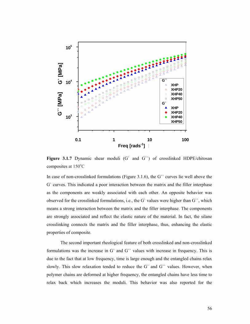
56
0.1 1 10 100
103
104
105
Freq [rad-s-1]
G`` XHP XHP20 XHP40 XHP50
G` XHP XHP20 XHP40 XHP50
G`
[MP
a]G
`` [
MP
a]
Figure 3.1.7 Dynamic shear moduli (G` and G``) of crosslinked HDPE/chitosan
composites at 150oC
In case of non-crosslinked formulations (Figure 3.1.6), the G`` curves lie well above the
G` curves. This indicated a poor interaction between the matrix and the filler interphase
as the components are weakly associated with each other. An opposite behavior was
observed for the crosslinked formulations, i.e., the G` values were higher than G``, which
means a strong interaction between the matrix and the filler interphase. The components
are strongly associated and reflect the elastic nature of the material. In fact, the silane
crosslinking connects the matrix and the filler interphase, thus, enhancing the elastic
properties of composite.
The second important rheological feature of both crosslinked and non-crosslinked
formulations was the increase in G` and G`` values with increase in frequency. This is
due to the fact that at low frequency, time is large enough and the entangled chains relax
slowly. This slow relaxation tended to reduce the G` and G`` values. However, when
polymer chains are deformed at higher frequency, the entangled chains have less time to
relax back which increases the moduli. This behavior was also reported for the
Freq [rads-1]

57
compatibilized low density polyethylene/polyoxyethylene (LDPE/POE) blend by
Baghaei et al [274].
In Figures 3.1.6, 3.1.7 and 3.1.8, it was also observed that both the dynamic shear moduli
and the complex viscosities of the crosslinked and the non-crosslinked formulations
increase, with increasing amount of chitosan loading. The G`` values of non-crosslinked
formulations increased stepwise with increase in chitosan loading. The increase in G``
values with chitosan loading corresponds to weak interaction between the matrix and the
filler interphase. As chitosan is hydrophilic and polyethylene is hydrophobic in nature,
therefore, the resultant composite of these two components was immiscible due to
different chemical natures. This was the main factor which enhanced the G`` values at
different chitosan loadings in non-crosslinked formulations. In Figure 3.1.7, the silane
crosslinked formulations showed opposite behavior. Instead of G``, G` values gradually
increased with increasing chitosan loadings. At higher chitosan loadings, the degree of
crosslinking increases and the elastic nature dominates. This behavior corresponds to
strong interaction between the matrix and the filler.
Figure 3.1.8 Complex viscosities η*of HDPE/chitosan composites at 150oC
0.1 1 10 100
103
104
105 HP HP20 HP40 HP50
XHP XHP20 XHP40 XHP50
Vis
cosi
ty [
Pa-
s]
Freq[rads-1]

58
Figure 3.1.8 depicts complex viscosities of silane crosslinked and non-crosslinked
formulations at 150oC. The complex viscosities were lower at higher frequency. This is
due to the strong shear thinning behavior of the composite in molten state [274]. It is also
seen that the silane crosslinked formulations have higher complex viscosities than the
non-crosslinked formulations due to the formation of network structure which causes
greater resistance under shear flow. Besides this, the amount of filler loading also
increased the complex viscosities for both types of formulations.
3.1.8 Melt flow index of HDPE/chitosan composites
Melt flow index is the rheological property that corresponds to the melt flow behavior of
thermoplastic. MFI of crosslinked samples were not determined due to their crosslinked
nature.
Table 3.1.4 Melt flow indices of non-crosslinked HDPE/chitosan composites
Sample Code HP HP20 HP30 HP40 HP50
Melt Flow Index 2.03 1.8 1.5 1.3 0.6
Table 3.1.4 shows melt flow indices of non-crosslinked composites. It is observed that
MFI values followed a decreasing trend with increasing amount of chitosan loading. This
behavior is attributed to the chain entanglement and the particle size of the chitosan. The
chitosan particles offer great resistance to the chain mobility and this effect was more
pronounced at higher concentration of chitosan. Thus, restricted chain mobility lowered
MFI at higher chitosan loading. This behavior also explained the correlation of MFI and
complex viscosity as discussed earlier in section 3.1.7, as high concentration of chitosan
particles increased the complex viscosity of non-crosslinked samples. This showed
inverse relation between MFI and complex viscosity.
3.1.9 Tensile properties of HDPE/chitosan composites
Table 3.1.5 presents the tensile properties of non-crosslinked and crosslinked
composites. It illustrates that tensile strength of crosslinked composites was much higher
than the non-crosslinked composites and the elongation at break (Eb) decreased
drastically in these composites. The tensile strengths of virgin HP and XHP were 8.1
MPa and 9.3 MPa, respectively. The tensile strength of crosslinked samples increased up
to 12.9%. Similarly, XHP20 (14.4 MPa) shows 47.1% enhancement as compared to
HP20 (7.6 MPa). The maximum tensile strength was observed for XHP50 (27.4 MPa)

59
which was 79.4% greater than HP50 (5.6 MPa). Both the non-crosslinked and
crosslinked composites showed poor elongation properties but the effect was more
pronounced in the non-crosslinked formulations. The maximum value of percentage
elongation was seen in XHP20 which was 21.4% while HP20 showed 18.1%.The
percentage elongation values decreased with higher chitosan loading. Both HP50 and
XHP50 showed minimum percentage elongation values which were 7.3% each. In fact,
at higher filler loading, chains mobility reduces and the Eb values decreases. This affect
was also reported for wood/thermoplastic composite and HDPE/starch reactive blend
[275, 276]. The high tensile properties of crosslinked composites were attributed to the
strong interaction between the HDPE/chitosan interphase.
Table 3.1.5 Tensile properties of HDPE/chitosan composites
Samples TS (MPa) Eb (%) Samples TS (MPa) Eb (%)
HP 8.1±1.0 403.3±9.2 XHP 9.3±0.5 336.9±7.3
HP20 7.6±1.3 18.1±1.0 XHP20 14.4±1.5 21.4±2.5
HP40 5.7±0.7 8.0±0.5 XHP40 25.7±1.7 9.3±1.3
HP50 5.6±0.5 7.3±0.5 XHP50 27.4±2.9 7.3±1.8
3.1.10 Short-term creep test of HDPE/chitosan composites
Figure 3.1.9 shows creep analysis of both non-crosslinked and crosslinked formulations.
Short-term creep experiments were carried out by dynamic mechanical thermal analyzer.
The experiments were performed at 60oC for 5 h under the static stress of 2 MPa. In
Figure 3.1.9, the non-crosslinked formulations show greater deformation as compared to
the crosslinked formulations. It is seen that deformation of these composites decreased
with increasing amount of chitosan loading. The highest deformation was observed for
virgin HP as compared to XHP. The XHP50 showed less deformation than HP50. The
lower deformation in the crosslinked composites was associated with silane crosslinking
which holds the macromolecular chains firmly whereas in non-crosslinked composites
the molecular chains are free to move and the hydrophobic-hydrophilic repulsions
between HDPE and chitosan further facilitate this phenomenon.

60
Figure 3.1.9 Creep analysis of non-crosslinked and crosslinked HDPE/chitosan
composites at 60oC
3.1.11 Scanning electron microscopy of HDPE/chitosan composites
Figures 3.1.10 and 3.1.11 depict the scanning electron micrographs of the fractured
surfaces of HP30, HP50 and XHP50 formulations. Figure 3.1.10 (a, b, c) shows some
clean surfaces of loosely embedded particles in polyethylene matrix. Some prominent
gaps are also observed between the matrix and filler interphase which indicates poor
miscibility. In Figure 3.1.11 (a, b, c, d), the XHP50 showed better adhesion between
chitosan and HDPE matrix. Besides this, the gaps between the matrix and filler
interphase are decreased. The matrix seems to adhere to the chitosan particles very well.

61
Figure 3.1.10 Scanning electron micrographs of non-crosslinked HDPE/chitosan
composite: HP30 (a) and HP50 (b, c)
c
Matrix
Filler
b
a
c
b

62
Figure 3.1.11 Scanning electron micrographs of crosslinked HDPE/chitosan composite
(XHP50) at different magnifications
Figure 3.1.12 (a) shows elemental analysis of XHP50 by Energy-dispersive X-ray
Spectroscopy (EDS). In Figure 3.1.12 (a), the marked region of chitosan particles
showed some characteristic elemental peaks. The presence of Si peak gives evidence
about the crosslinking reaction between chitosan and polyethylene matrix. It also showed
the uniform distribution of vinyl(triethoxy)silane in the crosslinked composites. Some
interesting peaks of sodium, calcium and aluminum metals were also found which had
already been reported for the commercially available chitosan [277].
In the light of above discussion, a good compatibility and strong interaction between the
components was achieved in these composites.
60 µm 80 µm
(d) (c)
10 µm 50 µm
(a) (b)

63
Figure 3.1.12 EDS analysis of crosslinked HDPE/chitosan composite: XHP50 (a, b)
(b
(a)

64
3.2 Linear low density polyethylene/starch/sepiolite composites
Linear low density polyethylene is widely used in packaging industries. The purpose of
this study is to develop new polyethylene/starch/sepiolite composites, which are
expected to be environment-friendly. Starch was selected as a biodegradable additive
because of its low cost and availability. In addition to starch, sepiolite clay mineral is
also incorporated in LLDPE. It has been reported in the literature that thermal and
mechanical properties of polyethylene can be improved using sepiolite [278]. Thus, it
was expected that the addition of sepiolite would also improve the thermal and
mechanical properties of LLDPE/starch composite. Twenty six formulations were
prepared by varying the starch and sepiolite contents. All those formulations having
30phr starch loading have optimum tensile properties and were further characterized.
3.2.1 Mechanism of silane crosslinking in LLDPE/starch/sepiolite composites
The peroxide-induced grafting and crosslinking reactions of silane were previously
explained in scheme 3.1. In this section, hydrolysis and condensation reactions of silane
moieties with starch and sepiolite will be discussed. In general, interaction of silane
coupling agents with starch and sepiolite mainly proceeds through following steps [179]:
(1) Hydrolysis: The silane monomers are hydrolyzed in the presence of water and
catalyst (DBTDL), liberating alcohol and yielding reactive silanol groups as shown in
[scheme 3.3 (a)].
(2) Self condensation: During the hydrolysis process, the concomitant condensation of
silanol groups takes place which is termed as self-condensation reaction. The self-
condensation reaction of silane-grafted polyethylene chains increases the degree of
crosslinking [scheme 3.3 (b)].
(3) Condensation of silanol groups with starch and sepiolite: The silanol groups may also
condense with hydroxyl groups of starch and sepiolite, thus, forming an ether linkage
which connects the polyethylene with starch and sepiolite via siloxane bond [scheme 3.3
(c, d)].
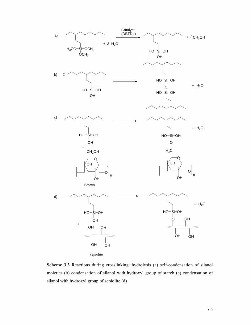
65
Si
OCH3
H3CO OCH3
SiHO OH
SiHO OH
CH3OH3
Si
OH
HO OH
SiHO OH
+
Si
OH
HO OH
Catalyst(DBTDL)
3 H2O+
2
H2O+O
SiHO OH
O
H2O+
OH
a)
b)
c)
O
CH2OH
OH
OH
O
+
O
H2C
OH
OH
O
Starch
nn
d)
SiHO OH
OH+
SiHO OH
O
H2O+
OHOH
OH OH
OH
OH OH
Sepiolite
Scheme 3.3 Reactions during crosslinking: hydrolysis (a) self-condensation of silanol
moieties (b) condensation of silanol with hydroxyl group of starch (c) condensation of
silanol with hydroxyl group of sepiolite (d)

66
10010
3.2.2 Particle size distribution of starch and sepiolite
In thermoplastic composites, the particle size distribution and dispersion are vital to
understand the rheological, mechanical and thermal aspects. The larger particle size of
filler and additives usually leads to weak mechanical properties. The particle size
distributions of starch and sepiolite are shown in Figure 3.2.1 (a, b). The average particle
size of starch varies from 10 μm to 100 μm. The particles with size between 50 μm to 60
μm consisted of 80% of the total volume. Similarly, in case of sepiolite the average
particle size was in the range of 8 μm to 10 μm which contributes more than 90% by
volume, while the particles with size less than 2 μm contribute 20% by volume. The
particle size of less than 2 μm of sepiolite was expected to improve the mechanical and
thermal properties of the resultant composite.
Figure 3.2.1 Particle size distribution of starch (a) and sepiolite (b)
Particle size in (µm)1000 1
Vo
lum
e (%
)
50
100 (a)
1
a
b

67
3.2.3 Gel content analysis of LLDPE/starch/sepiolite composites
The gel content analysis of crosslinked composite is presented in Table 3.2.1. These
results show that percentage degree of crosslinking gradually increases with increasing
amount of starch in these composites. The highest degree of crosslinking was observed
for the composite with 45phr starch loading, whereas the composite having 15phr starch
loading showed lowest gel content. This behavior is attributed to the dehydration and
condensation reactions of silane crosslinking agent. The probability of condensation
reaction of silanol group with hydroxyl group of starch increases as the starch loading
increases.
Table 3.2.1 Gel content analysis of LLDPE/starch/clay composites
Sample code
Gel content (%)
Sample code
Gel content(%)
Sample code
Gel content(%)
XLLS 2/15 18 XLLS 2/30 27 XLLS 2/45 35
XLLS 4/15 24 XLLS 4/30 31 XLLS 4/45 41
XLLS 8/15 16 XLLS 8/30 20 XLLS 8/45 29
Another factor is the effect of sepiolite loading on gel content. In these
composites, the sepiolite content was varied from 2phr to 8phr. The gel content value
first increases from 2phr to 4phr sepiolite loading and then drops off with 8phr sepiolite
loading. The lowering of gel content at this loading might be due to utilization of silanol
group by sepiolite. Therefore, the number of available silanol group for the crosslinking
of the polyethylene-grafted silane is drastically reduced.
3.2.4 Thermogravimetric analysis of LLDPE/starch/sepiolite composites
Figure 3.2.2 shows TGA thermograms and Table 3.2.2 shows percentage weight loss of
non-crosslinked and crosslinked composites as a function of temperature. Both the non-
crosslinked and crosslinked composites showed similar degradation behavior. However,
improved thermal stability was observed for crosslinked composites compared to non-
crosslinked composites.
The first stage of degradation showed minor changes in the curves up to 240C.
These little changes in the curves are associated to water evaporation which was
absorbed during the crosslinking reaction in boiling water. The second stage of

68
degradation ranging from 241C to 418C corresponded to the decomposition of starch.
Starch is thermally-unstable natural polymer as compared to polyethylene and its
degradation involved dehydration; ring scission and decomposition reactions [271]. The
third major stage was attributed to the decomposition of LLDPE, which involved C-C
and C-H bond breaking. This stage of degradation was observed from 418C to 510C.
Figure 3.2.2 TGA thermograms of LLDPE/starch/sepiolite composites
Table 3.2.2 shows major weight losses at three different temperatures 311C,
418C and 542C. At 311○C, the LLS 2/30 has 2.5% more decomposition than XLLS
2/30. At 418C, starch was totally decomposed and at this temperature LLS 2/30 showed
1.0% higher decomposition than XLLS 2/30. Similarly, the LLS 4/30 showed greater
weight loss as compared to its crosslinked congener. The difference between the weight
losses were 1.2% and 0.5% at 311C and 418C, respectively. The high thermal stability
of crosslinked composite is due to crosslinking reaction by VTMS. The percentage
weight residue of XLLS 4/30 at 550C was 2% higher than LLS 4/30. Similarly, the
percentage weight residue of XLLS 8/30 was 1.0% greater than LLS 8/30. A slightly

69
higher percentage of weight residues of crosslinked composites are mainly because of the
silane crosslinking and the amount of sepiolite loading to some extent.
Table 3.2.2 Percentage weight loss and weight residue of LLDPE/starch/sepiolite composites
Sample % weight loss at
311○C % weight loss at
418○C % weight residue at
542○C
LLS 2/30 12.1 18.7 92.5
XLLS 2/30 9.5 17.7 92.4
LLS 4/30 10.7 17.0 90.9
XLLS 4/30 9.5 16.5 88.9
LLS 8/30 10.2 16.7 89.1
XLLS 8/30 9.7 16.1 88.0
Table 3.2.2 also reveals the effect of sepiolite loading on these composites,
greater the sepiolite loading greater is the stability of these composites. At 418C and at
2phr sepiolite loading, the percentage weight loss of LLS 2/30 and XLLS 2/30 were
18.7% and 17.7%, respectively, whereas at 4phr sepiolite loading and at 418C the
percentage weight loss of LLS 4/30 and XLLS 4/30 were 17% and 16.5%, respectively.
When the sepiolite loading was increased to 8phr the percentage weight loss further
decreased which indicates better thermal stability.
3.2.5 Differential scanning calorimetry of LLDPE/starch/sepiolite composites
Table 3.2.3 shows melting temperature (Tm), heat of fusion (ΔHf) and percentage
crystallinity of LLDPE/starch/sepiolite composites.
Table 3.2.3 shows negligible variation among the Tm values of both non-
crosslinked and crosslinked composites. All the crosslinked formulations have slightly
lower percentage crystallinity and Tm values as compared to non-crosslinked
formulations. The lowering of percentage crystallinity and Tm values of crosslinked
samples were associated to the network formation as a result of silane crosslinking which
reduces the chain flexibility and hinders the ordering of PE chains into crystalline
regions [272]. This tendency has also been reported for thermoplastic wood composite
by Magnus et al [268].

70
Table 3.2.3 also depicts the effect of starch and sepiolite loading on the
percentage crystallinity and Tm values. At higher starch and sepiolite loadings, the
percentage crystallinity and Tm values showed a decreasing trend. The maximum
percentage crystallinity was observed for non-crosslinked sample LLS 2/30 which is
25.9% whereas LLS 8/45 showed the minimum value of percentage crystallinity, i.e.,
21.9%. These results show that greater quantity of filler inhibits close packing of LLDPE
and this phenomenon reduced the percentage crystallinity of the composites. Similarly,
the percentage crystallinity of crosslinked samples XLLS 2/30 and XLLS 8/45 are 25.6%
and 20.3%, respectively, showing the same trend. In case of crosslinked composites, both
the silane crosslinking and the amount of filler tended to decrease the percentage
crystallinity, the reason being the inability of PE chains to arrange themselves.
Table 3.2.3 DSC analysis of LLDPE/starch/sepiolite composites
Sample code
Tm
(oC) ΔHf (J/g)
Crystallinity (%)
Sample code
Tm
(oC) ΔHf
(J/g) Crystallinity
(%)
LLS 2/30 121.2 75.9 25.9 XLLS 2/30 120.3 75.0 25.6
LLS 2/45 120.8 66.1 22.5 XLLS 2/45 120.5 60.1 20.5
LLS 4/30 121.2 74.2 25.3 XLLS 4/30 121.1 72.0 24.5
LLS 4/45 121.1 65.2 22.2 XLLS 4/45 120.7 63.8 21.7
LLS 8/30 121.3 75.3 25.6 XLLS 8/30 121.0 73.5 25.1
LLS 8/45 121.5 64.3 21.9 XLLS 8/45 121.2 59.6 20.3
3.2.6 Melt rheology of LLDPE/starch/sepiolite composites
Figure 3.2.3 shows dynamic shear storage modulus of both non-crosslinked and
crosslinked formulations. The crosslinked formulations showed higher G` values than the
non-crosslinked composites. The increase in G` values were attributed to the elastic
nature of the crosslinked composites. Both the crosslinked and non-crosslinked
composites showed a regular trend at lower frequency. The anomalous behavior of
crosslinked XLLS 4/30 at higher frequency is associated to its higher gel content,
whereas at lower frequency both crosslinking and the amount of filler tend to increase
the G` values of XLLS 8/45. The increase in G` values with increasing frequency of both
non-crosslinked and crosslinked composites are related to molecular chain relaxation

71
phenomena. At higher frequency, the entangled chains have short time to relax back,
thus, increasing the G` values [274].
Figure 3.2.3 Dynamic shear storage modulus G`of LLDPE/starch/sepiolite composites at
150oC
Figure 3.2.4 indicates the dynamic shear loss modulus G`` curves of non-
crosslinked and crosslinked composites. The G`` is also called viscous modulus because
it corresponds to the viscous nature of the material. In Figure 3.2.4 the G`` curves of the
non-crosslinked composites are well above the crosslinked composite. The higher G``
curves of non-crosslinked composites explain the weak interactions among the
components. Besides this, G`` also increased with increasing frequency and quantity of
filler.
Figure 3.2.5 gives the complex viscosity of non-crosslinked and crosslinked
composites. The crosslinked composites showed higher complex viscosities which were
attributed to the formation of network structures that offer greater resistance to the
applied stress. The η* of both non-crosslinked and crosslinked composites also depends
upon the amount of filler. At higher filler loading, higher η* values were observed for
both types of composites. Figure 3.2.5 shows that η* is also frequency-dependent and
decreased with increasing operating frequency. This behavior is called shear thinning
effect in molten state [274].

72
Figure 3.2.4 Dynamic shear loss modulus G``of LLDPE/starch/sepiolite composites at 150oC
Figure 3.2.5 Complex viscosity η*of LLDPE/starch/sepiolite composites at 150oC

73
3.2.7 Tensile properties of LLDPE/starch/sepiolite composites
Table 3.2.4 shows tensile properties of LLDPE/starch/sepiolite composite. The
crosslinked composites showed improved tensile strength (TS) and reduced elongation at
break (Eb) as compared to non-crosslinked composites. The TS of LLDPE was 38.0
(MPa) and that of XLLDPE was 39.1 (MPa) which was improved up to 2.9%. Eb was
reduced from 974.9% to 727.2% in the crosslinked sample, with overall reduction of
25.4%. The high TS and reduced Eb values of crosslinked composites were attributed to
the network structure, which is also reported by many authors [275, 276].
It was observed that TS and Eb values of the non-crosslinked and crosslinked
composite reduced at higher starch loading. The reductions in the tensile strength with
30phr starch loading in LLS 30 and XLLS 30 were 20.9% and 36.1% relative to the
composite having 15phr starch loading. Similarly, by comparing the composites having
45phr starch loading with 15phr starch loading, the TS values of LLS 45 and XLLS 45
were further found to decrease by 43.1% and 55%, respectively. The Eb values of both
non-crosslinked and crosslinked composites also showed reducing trend with high starch
loading. The reason is that at higher filler loading the chain mobility reduced and the Eb
values decreased. The effect of sepiolite loading on the tensile properties of these
composites showed that TS and Eb of both non-crosslinked and crosslinked composites
decreased with increasing sepiolite loading. The reduction in the TS with 8phr sepiolite
loading in LLSP 8 and XLLSP 8 was 18.8 and 17.7% relative to the composite having
2phr sepiolite loading.
Table 3.2.4 also illustrates the combined effect of starch and sepiolite on the TS
and Eb values of non-crosslinked and crosslinked composites. At lower starch and
sepiolite loading, the TS and Eb values were high as compared to the high starch and
sepiolite loading. The highest TS was observed for LLS 2/15 (30.6 MPa) and XLLS 2/15
(32.0 MPa), whereas lowest TS values were observed for LLS 8/45 and XLLS 8/45
which were 17.4 MPa and 19.2 MPa, respectively. The increase in TS is associated with
filler loading. At lower filler loading, the hydrophobic and hydrophilic repulsion is
minimum, whereas at higher filler loading this repulsion is maximum and hence the
tensile properties decrease.

74
Table 3.2.4 Tensile properties of LLDPE /starch/sepiolite composites
Samples TS(MPa) Eb (%) Samples TS (MPa) Eb (%)
LLDPE 38.0 ± 3 974.9 ± 1 XLLDPE 39.1 ± 2 727.2 ± 2 LLS 15 31.2 ± 5 912.4 ± 3 XLLS 15 36.9 ± 6 659.8 ± 3 LLS 30 25.8 ± 2 804.7 ± 4 XLLS 30 27.1 ± 1 543.8 ± 1 LLS 45 21.8 ± 1 730.5 ± 2 XLLS 45 23.8 ± 4 307.1 ± 2 LLSP 2 40.4 ± 3 987.1 ± 6 XLLSP 2 41.7 ± 7 743.5 ± 4 LLSP 4 37.5 ± 4 979.2 ± 2 XLLSP 4 38.0 ± 8 693.4 ± 5 LLSP 8 34.0 ± 5 774.8 ± 1 XLLSP 8 35.4 ± 8 633.9 ± 7
LLS 2/15 30.6 ± 0.4 771.0 ± 1 XLLS 2/15 32.0 ± 0.3 687.9 ± 1 LLS 2/30 25.5 ± 0.3 720.1 ± 1 XLLS 2/30 27.1 ± 0.2 635.7 ± 1 LLS 2/45 20.7 ± 0.2 635.1 ± 1 XLLS 2/45 21.9 ± 0.4 553.0 ± 2 LLS 4/15 29.7 ± 0.4 710.4 ± 1 XLLS 4/15 30.3 ± 0.3 640.9 ± 1 LLS 4/30 23.4 ± 0.2 659.8 ± 1 XLLS 4/30 25.0 ± 0.5 590.4 ± 2 LLS 4/45 18.8 ± 0.3 610.1 ± 1 XLLS 4/45 20.4 ± 0.5 539.9 ± 1 LLS 8/15 27.9 ± 0.4 646.5 ± 1 XLLS 8/15 29.2±0.2 603.7 ±1 LLS 8/30 22.4 ± 0.3 583.2 ± 1 XLLS 8/30 24.1±0.4 506.0 ±2 LLS 8/45 17.4 ± 0.5 559.8 ± 1 XLLS 8/45 19.2±0.4 465.2 ±1
3.2.8 Scanning electron microscopy of LLDPE/starch/sepiolite composites
Fig. 3.2.6 (a) shows scanning electron micrograph of non-crosslinked formulation LLS
4/30. It shows good dispersion and uniform distribution of starch and sepiolite in the
LLDPE matrix. Dispersion and distribution of the filler in the matrix play a vital role and
affect the mechanical properties of the resultant composite.
Fig. 3.2.6 (b, c) shows fractured surfaces of non-crosslinked (LLS 4/30) and
crosslinked formulations XLLS 4/30. Some gaps are observed in LLS 4/30, showing
poor adhesion among the components, whereas in Fig. 3.2.6 (c) the filler particles in
crosslinked formulations are well embedded in the matrix and showed improved
compatibility. This strong interaction among the filler-matrix interphase is attributed to
the silane crosslinking. Some fine particles of sepiolite were also observed both in non-
crosslinked and crosslinked composites. These smaller particles are evenly distributed in
the matrix and can support the larger starch particles during applied mechanical stress
thus acting as supporting filler.
In conclusion, SEM images illustrated better compatibility of crosslinked composites
than non-crosslinked composites.

75
Figure 3.2.6 Scanning electron micrographs of LLDPE/starch/sepiolite composite: LLS
4/30 (a, b) XLLS 4/30 (c)
a
b
c

76
3.3 High density polyethylene/carboxymethyl cellulose composites
In this section, the results of the high density polyethylene and carboxymethyl cellulose
(HDPE/CMC) composite will be discussed. CMC is a water soluble form of cellulose
and its blending with polyethylene produced a material which will be easily biodegraded
in soil containing water and micro-organisms. Therefore, a series of non-crosslinked and
crosslinked formulations of HDPE/CMC composite were prepared, containing 20 phr to
a maximum of 50 phr CMC loading. At 50 phr loading, some mechanical properties such
as {tensile strength} tend to deteriorate so compositions containing more than 50 phr
were not prepared.
3.3.1 Mechanism of silane crosslinking in HDPE/CMC composites
The peroxide-induced grafting and crosslinking reactions of silane were previously
explained in scheme 3.1. Scheme 3.4 shows the hydrolysis and condensation reactions of
silane moieties with CMC.
Si
OC2H5
C2H5O OC2H5
SiHO OH
SiHO OH
C2H5OH3
Si
OH
HO OH
SiHO OH
+
Si
OH
HO OH
Catalyst(DBTDL)
3 H2O+
2
H2O+O
SiHO OH
O
ROH+
OH+
a)
b)
c)
OCH2OR
OR
OR
H
HH
O
H
R= CH2CO2H
Carboxymethyl Cellulose
OCH2
OR
OR
H
HH
O
H
n n
n
n
n
n
n
n n
Scheme 3.4 Reactions during crosslinking: hydrolysis (a) self condensation of silanol
moieties (b) condensation of silanol with OR group of carboxymethyl cellulose (c)

77
The silane crosslinking reactions of polyethylene were carried out in boiling
water. The first step during crosslinking was the hydrolysis of the silane into the silanol
as shown in scheme 3.4 (a). It has been reported in the literature that silane crosslinking
reaction initiates during processing [179] as CMC already contains some moisture,
which causes hydrolysis of alkoxy groups. The second step was the condensation of the
silanol groups of the grafted polyethylene which is termed as self condensation reaction
[see scheme 3.4 (b)]. The silanol groups may also condense with alkoxy group of CMC,
thus, forming an ether linkage which connects the polyethylene with CMC via siloxane
bond [scheme 3.4 (c)]. The presence of above-mentioned linkages was confirmed by
FTIR analysis [section 3.3.3].
3.3.2 Particle Size Distribution of CMC
The particle size distribution of CMC is shown in Figure 3.3.1. The particle size varies
from 0.8 μm to 90 μm and the average particle size is in the range of 6 μm to 20 μm. The
particles with sizes between 0.5 μm to 2 μm consist of less than 10% of the total volume.
The particles with size greater than 20 μm contribute 30% by volume, whereas the
particles with sizes between 1 μm to 10 μm contribute 40% by volume.
Figure 3.3.1 Particle size distribution of carboxymethyl cellulose
0.1 1 10 100

78
3.3.3 FTIR analysis of HDPE/CMC composites
Figure 3.3.2 shows FTIR spectra of virgin PE, non-crosslinked (HC30) and crosslinked
(XHC30) composites. The important absorption peaks of siloxane appeared in the range
of 800 cm-1 to 1200 cm-1. The XHC30 showed characteristic absorption peaks of (Si-O-
Si) at 1050 cm-1 and 1021 cm-1[268, 269]. The symmetric vibration of (Si-O-Si) was also
observed at 812 cm-1 [268] which was absent in the non-crosslinked HC30 and virgin PE
samples. The characteristic absorption peaks of CMC were found in both non-
crosslinked and crosslinked formulations. The stretching frequencies of carboxyl and
hydroxyl group appeared at 1581 cm-1 and 3390 cm-1, respectively. The important
absorption band appearing at 1159 cm-1 was assigned to Si-O-C, which reflects the
crosslinking reaction [270].
Figure 3.3.2 FTIR spectra of HDPE/CMC composites
3500 3000 2500 2000 1500 1000 5000.30
0.25
0.20
0.15
0.10
0.05
0.00
-0.05
1050
1159
1581
33901369
1021
916
812
(a)
(b)
(c)
Tra
nsm
itta
nce
(%
)
Wave number (cm-1)
(a) PE(b) HC30(c) XHC30
Wave number (cm-1)

79
3.3.4 Thermogravimetric analysis of HDPE/CMC composites
Figure 3.3.3 shows weight loss of HDPE/CMC composites against temperature and
Table 3.3.1 summarize thermal degradation temperature for major weight losses. The
virgin PE and XPE samples showed single stage of degradation in the range of 410oC to
500oC. The silane crosslinked XPE exhibited higher thermal stability than virgin PE.
The thermograms for non-crosslinked HDPE/CMC composites showed three stages of
degradation. The first stage ranging from 90oC to 150oC was attributed to the loss of
water present in CMC due to its hygroscopic nature. The second stage ranging from
250oC to 410oC was due to thermal degradation of CMC. During this stage, dehydration,
ring scission and decomposition of the CMC occurred [271]. The third stage (ranging
from 410oC to 500oC) was attributed to the decomposition of HDPE matrix as observed
in case of virgin PE. The crosslinked HDPE/CMC composites also showed three stages
of degradation. The first stage ranging from 90oC to 150oC was attributed to the loss of
water for both non-crosslinked and crosslinked composites. The second and third stages
of degradation were similar for the non-crosslinked and crosslinked composites.
Figure 3.3.3 TGA thermograms of HDPE/CMC composites
I
II
III

80
Table 3.3.1 shows weight loss and weight residues of non-crosslinked and
crosslinked composites at 150○C, 410○C and 500○C. At 150○C, the moisture contents of
both types of composite were completely lost but comparatively the non-crosslinked
composite shows greater weight loss. The degradation of virgin PE and crosslinked XPE
was not observed at 150○C. The decomposition of CMC started at 410○C. The major
weight loss was observed for the non-crosslinked composites HC30 and HC50, which
are 18.4% and 13.4%, respectively. At 410○C, the crosslinked composites XHC30 and
XHC50 showed lower weight loss of 10% and 4.7%, respectively. The minimum weight
residue (3%) was noticed for virgin PE and the maximum weight residue (16%) was
observed for XHC50 at 500C. This higher percentage of weight residue of crosslinked
composites are mainly because of the silane crosslinking.
Table 3.3.1 Percentage weight loss and weight residue of HDPE/CMC composites
Sample code
% Weight loss at 150○C
% Weight loss at 410○C
% Weight residue at
500○C
PE 0.0 0.0 3.0
XPE 0.0 0.0 6.6
HC30 2.2 18.4 8.1
XHC30 0.9 10.0 11.3
HC50 1.1 13.4 13.1
XHC50 0.2 4.7 16.0
3.3.5 Differential scanning calorimetry of HDPE/CMC composites
Table 3.3.2 shows melting temperature (Tm), heat of fusion (∆Hf) and the percentage
crystallinity of HDPE/CMC composites. Almost no difference was observed among the
Tm values of non-crosslinked and crosslinked formulations but the percentage
crystallinity differed to an appreciable extent. Comparatively, the crosslinked samples
showed lower crystallinity than the non-crosslinked samples. The virgin PE has 63.4%
crystallinity, whereas XHP has 61.7% and the observed difference was 1.7%. Similarly,
the percentage crystallinity of HC40 and HC50 were 41.8% and 41.1% while that of
XHC40 and XHC50 were 40.4 and 39.2%, respectively. In this case, there is a total
reduction of 1.4% and 1.9%, respectively. As compared to PE, the addition of 20 phr of

81
CMC reduced its crystallinity from 63% to 52%, while at 40 and 50 phr CMC loading,
same percentage of crystallinity was observed. The lowering of percentage crystallinity
for crosslinked formulations was due to the formation of network structure [272]. The
network reduced the chain flexibility which reduced percentage crystallinity. Similar
tendency has been previously observed in thermoplastic wood composite [268].
Table 3.3.2 DSC analysis of HDPE/CMC composites
Sample code
Tm
(oC) ΔHf
(J/g) Crystallinity
(%) Sample
code Tm
(oC) ΔHf
(J/g) Crystallinity
(%)
PE 130.3 184.1 63.4 XPE 129.8 179.1 61.7
HC20 129.7 151.5 52.2 XHC20 129.3 145.6 50.2
HC40 129.5 121.3 41.8 XHC40 129.1 117.3 40.4
HC50 129.5 119.4 41.1 XHC50 129.2 113.9 39.2
3.3.6 Melt rheology of HDPE/CMC composites
Figures 3.3.4 and 3.3.5 give the dynamic shear moduli of non-crosslinked and
crosslinked formulations at 150oC and the complex viscosities of these formulations are
shown in Fig. 3.3.6. In the case of non-crosslinked formulations (Fig. 3.3.4), the G``
curves were observed at higher values than the G` curves. This behavior was exhibited
by composites having poor interaction between the matrix-filler interphase as the
components are weakly associated with each other. On the other hand, an opposite
behavior was observed for the crosslinked formulations and now the G` values were
higher than G`` which means a strong interaction between the matrix-filler interphase.
The components are strongly associated to each other and reflect the elastic nature of the
material. In fact, the silane crosslinker connected the matrix-filler interphase which
enhanced the elastic properties of these materials.
The second important rheological feature of both crosslinked and non-crosslinked
formulations was the increase in G` and G`` values with increase in frequency. This was
due to the fact that at low frequency, time is large enough and the entangled chains relax
slowly. This slow relaxation tends to reduce the G` and G`` values. However, when the
polymer chains were deformed at higher frequency, the entangled chains have less time
to relax back which increases the moduli. This behavior was first reported by Baghaei et
al for the compatibilized LDPE/POE blend [274].

82
The Figures 3.3.4, 3.3.5 and 3.3.6 revealed that both the dynamic shear moduli
and the complex viscosities of the crosslinked and the non-crosslinked formulations
increased with increasing amount of filler loading. The G`` values of non-crosslinked
formulations increased step-wise with increase in CMC loading. The increase in G``
values with filler loading corresponded to weak interaction between the matrix-filler
interface. As CMC is hydrophilic and polyethylene is hydrophobic in nature, therefore,
the resultant blend of these two components was immiscible. This was the main factor
which enhanced the G`` values at different filler loadings in non-crosslinked
formulations. In Fig. 3.3.5, the silane crosslinked formulations show opposite behavior.
Instead of G``, G` values gradually increased with higher loadings. This behavior
corresponds to strong interaction between matrix-filler interphase due to silane
crosslinking.
Figure 3.3.4 Dynamic shear moduli (G` and G``) of non-crosslinked HDPE/CMC
composites at 150oC

83
Figure 3.3.5 Dynamic shear moduli (G` and G``) of crosslinked HDPE/CMC composites
at 150oC
Figure 3.3.6 shows complex viscosities of non-crosslinked and crosslinked
HDPE/CMC composites. The crosslinked composites showed higher complex viscosities
which were attributed to the formation of network structure due to silane crosslinking.
The network structure causes greater resistance to the applied stress.
The complex viscosity of both non-crosslinked and crosslinked composite also
depended upon the amount of filler. At higher filler loading, higher η*values were
observed for both types of composites. Figure 3.3.6 shows that η*values were also
frequency dependent and decreased with increasing operating frequency. This behavior
is called shear thinning effect in molten state [274].

84
Figure 3.3.6 Complex viscosities η*of HDPE/CMC composites at 150oC
3.3.7 Tensile properties of HDPE/CMC composites
Table 3.3.3 shows the tensile strength (TS) and elongation at break (Eb) values of non-
crosslinked and crosslinked composites. It was observed that TS of crosslinked samples
was much higher than the non-crosslinked samples. The Eb values showed a decreasing
trend for both types of composites. The tensile strength of virgin PE and XPE were 8.1
MPa and 9.3 MPa, respectively. The tensile strength of XHP was increased up to 12.9%.
Similarly, the XHC20 (16.1MPa) showed 60.2% enhancement as compared to HC20 (6.4
MPa). The maximum tensile strength was observed for XHC40 (19.6 MPa) which was
61.7% greater than HC40 (7.5 MPa). In contrast, TS of non-crosslinked and crosslinked
composite showed a decreasing trend at 50 phr CMC loading because at higher filler
loadings the interactive forces between hydrophobic and hydrophilic chains become less
effective. The higher TS of XHC50 as compared to HC50 was due to the silane coupling
agent.
Both the non-crosslinked and crosslinked composites showed decreasing trend of
Eb values but this effect is well-defined in the non-crosslinked formulations. The
maximum Eb value was observed for XHC20 which is 19.1%, while HC20 showed
Freq

85
13.0%. The percentage elongation values decreased with higher CMC loading. Thus,
HC50 and XHC50 show minimum Eb values which are 9.6% and 11.7%, respectively.
This behavior is also reported in the literature [275, 276].
Table 3.3.3 Tensile properties of HDPE/CMC composites
Samples TS (MPa) Eb (%) Samples TS (MPa) Eb (%)
PE 8.1 ± 1 403 ± 9 XPE 9.3 ± 0.5 336 ± 7
HC20 6.4 ± 3 13.0 ± 1 XHC20 16.1 ± 2 19.1 ± 2
HC30 7.3 ± 1 14.3 ± 2 XHC30 17.5 ± 3 12.2 ± 1
HC40 7.5 ± 3 10.5 ± 1 XHC40 19.6 ± 1 15.2 ± 3
HC50 6.9 ± 1 9.6 ± 2 XHC50 14.9 ± 1 11.7 ± 2
3.3.8 Short-term creep test of HDPE/CMC composites
Figure 3.3.7 shows-short term creep test for both non-crosslinked and crosslinked
formulations. Short-term creep experiments were carried out by dynamic thermal
mechanical analyzer (DTMA). The creep analysis was carried at 60oC for 5 h under the
static mode.
The non-crosslinked composites showed greater deformation as compared to
crosslinked composites. The virgin PE had highest deformation as compared to XPE. It
can be seen that deformation of these composites decreased with increasing amount of
CMC loading. The least deformation was observed for XHC50 and HC50. The
crosslinked composites showed minimum deformations, which is attributed to
crosslinking reactions. The crosslinking holds the macromolecular chains firmly
whereas, in non-crosslinked composites, the molecular chains are free to move and the
hydrophobic-hydrophilic interactions between HDPE and CMC further facilitate this
phenomenon.

86
Figure 3.3.7 Creep analysis of non-crosslinked and crosslinked HDPE/CMC composites
at 60oC
3.3.9 Scanning electron microscopy of HDPE/CMC composites
Figure 3.3.8 (a, b) shows SEM images of the fractured surfaces of non-crosslinked
(HC30) and crosslinked (XHC30) composites. The particle size of CMC in non-
crosslinked sample (HC30) is greater than 10µm and is weakly bound to the PE matrix.
Wide gaps are visible between PE and CMC interface, which indicates weak interaction
that caused lowering of mechanical properties. The crosslinked formulation (XHC30)
showed strong adhesion between the matrix-filler interface. This behavior was attributed
to the VTES crosslinking agent that firmly bound the two immiscible components.

87
Figure 3.3.8 Scanning electron micrographs of HDPE/CMC composites: HC30 (a)
XHC30 (b)
(a)
(b)

88
CONCLUSIONS
These composites were prepared by a peroxide-initiated melt compounding technique.
Two types of silane, i.e., VTES and VTMS were used as crosslinking agents. The
crosslinked composites showed distinct absorption peaks of Si-O-C and Si-O-Si at 1105
cm-1 and 1020 cm-1 which confirmed the crosslinking reaction. Similarly, scanning
electron microscopy also confirmed good compatibility and strong interaction between
the matrix and the filler interphase. The degree of crosslinking was found to be directly
proportional to the amount of chitosan and CMC, while in case of
LLDPE/starch/sepiolite composites, it decreased with high sepiolite loading.
Thermogravimetric analysis showed higher thermal stability and percentage of weight
residues of the crosslinked composites. Differential scanning calorimetry showed
decreasing trend of percentage crystallinity and melting temperature with increasing
amount of chitosan, CMC and starch, which was associated to the network structure and
the disorder of close packing of polyethylene chains. Rheological behavior of all
composites was within linear viscoelastic region. The complex viscosities and dynamic
shear storage moduli G`of the crosslinked composites were higher than the non-
crosslinked composites; this showed improved compatibility and also the elastic nature
of the crosslinked structure. High tensile strength was observed in all the crosslinked
samples with reduced elongation at break. In case of HDPE/chitosan, the TS values
increased with high chitosan loading. However, the TS and Eb values of non-crosslinked
and crosslinked formulations of LLDPE/starch/sepiolite and HDPE/CMC composites
showed reducing trend with high starch, CMC and sepiolite loadings. Creep experiments
indicated small deformation in crosslinked composites as compared to the non-
crosslinked composites, which showed that silane crosslinking effectively linked the two
immiscible components.

89
FUTURE PLAN OF WORK
The prepared composites will be tested for biodegradation under different
environmental conditions such as air, water and soil. Chitosan-based composites will be
studied for anti-bacterial and anti-fungal properties. The crosslinking of these
composites will also be carried out using ionizing radiations. The structural, thermal,
mechanical and rheological properties of radiation crosslinked composite will be
compared to silane crosslinked and non-crosslinked composites. These composites will
also be examined under ultra violet (UV) radiation for ageing phenomenon.

90
REFERENCES
1. Morye, S. S.; Hine, P. J.; Duckett, R. A.; Carr, D. J.; Ward, I. M. A comparison
of the properties of hot compacted gel-spun polyethylene fibre composites with
conventional gel-spun polyethylene fiber composites. Compos Part A Appl Sci
Manuf. 1999, 30, 649-660.
2. George, R. N.; Carol, D. S. Poly(amidoamine), polypropylenimine, and related
dendrimers and dendrons possessing different 1-2 branching motifs: An overview
of the divergent procedures. Polymer. 2008, 49, 1-173.
3. Pegoretti, A.; Zanolli, A.; Migliaresi, C. Preparation and tensile mechanical
properties of unidirectional liquid crystalline single-polymer composites. Compos
Sci Technol. 2006, 66, 1970-1979.
4. Chou, T. W.; Kelly, A.; Okura, A. Fiber-reinforced metal-matrix composites.
Composites. 1985, 16, 187-206.
5. Schulte, K.; Minoshima, K. Damage mechanisms under tensile and fatigue
loading of continuous fiber-reinforced metal-matrix composites. Composites.
1993, 24, 197-208.
6. Chen, R.; Li, X. A study of silica coatings on the surface of carbon or graphite
fiber and the interface in a carbon/magnesium composite. Compos Sci Technol.
1993, 49, 357-362.
7. Chandrasekaran, L.; Robertson, J.G.; Godfrey, S. P.; Murgatroyde, D. P.
Advances in the fabrication of titanium metal matrix composite. Mater Sci Eng A.
1999, 263, 314-318.
8. Ponzi, C. Metal matrix composite fabrication processes for high performance
aerospace structures. Compos Manuf. 1992, 3, 32-42.
9. Goto, K.; Kagawa, Y. Fracture behavior and toughness of a plane-woven SiC
fiber-reinforced SiC matrix composite. Mat Sci Eng A. 1996, 211, 72-81.

91
10. Wert, J. A. Microstructures of friction stir weld joints between an aluminium-
base metal matrix composite and a monolithic aluminium alloy. Scripta Mater.
2003, 49, 607-612.
11. Miracle, D. B. Metal matrix composites from science to technological
significance. Compos Sci Technol. 2005, 65, 2526-2540.
12. Gergely, V.; Degischer, H. P.; Clyne, T. W. Metal Matrix Composites. Compr
Compos Mater, 2000, 23, 797-820.
13. Han, W.; Eckschlager, A.; Bohm, H. J. The effects of three-dimensional multi-
particle arrangements on the mechanical behavior and damage initiation of
particle-reinforced MMCs. Compos Sci Technol. 2001, 61, 1581-1590.
14. http://www.answers.com/topic/ceramics, (date of access, 03-02-2011)
15. Chermant, J. L.; Boitier, G.; Darzens, S.; Farizy, G.; Vicens, J.; Sangleboeuf, J.
C. The creep mechanism of ceramic matrix composites at low temperature and
stress, by a material science approach. J Eur Ceram Soc. 2002, 22, 2443-2460.
16. Sapuan, S. M.; Jacob, M. S. D.; Mustapha, F.; Ismail, N. A prototype knowledge-
based system for material selection of ceramic matrix composites of automotive
engine components. Mater Design. 2002, 23, 701-708.
17. Viswanathan, V.; Laha, T.; Balani, K.; Agarwal, A.; Seal, S. Challenges and
advances in nanocomposite processing techniques. Mater Sci Eng Rep. 2006, 54,
121-285.
18. Hegedusova, L.; Kovalcikova, A.; Ceniga, L.; Dusza. Contact strength and crack
formation in monolithic ceramic materials. Mater Sci Eng: A. 2010, 527, 1179-
1184.
19. Wilshire, B. High-temperature properties of monolithic ceramics. Mater Design.
1993, 14, 39-43.
20. Zhu, K.; Schmauder, S. Prediction of the failure properties of short fiber
reinforced composites with metal and polymer matrix. Comp Mater Sci. 2003, 28,
743-748.

92
21. Cho, J.; Joshi, M. S.; Sun, C. T. Effect of inclusion size on mechanical properties
of polymeric composites with micro and nano particles. Compos Sci Technol.
2006, 66, 1941-1952.
22. Parvatareddy, H.; Wilson, T. P. H.; Dillard, D. A. Impact damage resistance and
tolerance of high-performance polymeric composites subjected to environmental
aging. Compos Sci Technol. 1996, 56, 1129-1140.
23. Okuhara, Y.; Matsubara, H. Effects of fiber nonlinear properties on the
compressive strength prediction of unidirectional carbon-fiber composites.
Compos Sci Technol. 2005, 65, 2148-2155.
24. Garoushi, S.; Vallittu, P. K.; Lassila, L. V. J. Use of short fiber-reinforced
composite with semi-interpenetrating polymer network matrix in fixed partial
dentures. J Dent. 2007, 35, 403-408.
25. Fu, S. Y.; Feng, X. Q.; Lauke, B.; Mai, Y. W. Effects of particle size,
particle/matrix interface adhesion and particle loading on mechanical properties
of particulate polymer composites. Compos Part B: Eng. 2008, 39, 933-961.
26. Hine, P. J.; Olley, R. H.; Ward, I. M. The use of interleaved films for optimising
the production and properties of hot compacted, self reinforced polymer
composites. Compos Sci Technol. 2008, 68, 1413-1421.
27. Derrien, K.; Gilormini, P. The effect of moisture-induced swelling on the
absorption capacity of transversely isotropic elastic polymer matrix composites.
Int J Solids Struct. 2009, 46, 1547-1553.
28. http://www.Classification Ethylene copolymers History en.wikipedia.org/wiki/
Polyethylene, (date of access, 05-02-2011)
29. http://www.digitalebookden.com/chapter-1-history-and-physical- chemistry-of-
hdpe.html, (date of access, 05-02-2011)
30. http://www.amazon.com/LLDPE-Websters.History-1976, (date of access, 05-02-
2011)
31. Hoang, E. M.; Allen, N. S.; Liauw, C. M.; Fontan, E.; Lafuente, P. The thermo-
oxidative degradation of metallocene polyethylenes: Part 2: Thermal oxidation in
the melt state. Polym Degrad Stabil. 2006, 91, 1363-1372.

93
32. http://www.astm.org/Standards/D1248.htm, (date of access, 04-02-2011)
33. Kurtz, S. J. "VLDPE: A Break-through In flexible Linear Polyethylene",
ANTEC'85, Conference Proceedings for the Society of Plastic Engineers, Inc.
43rd Annual Technical Conference, 1985, 463-466.
34. http://accessscience.com/content/Polyolefin%20resins/535900(date of access, 04-
02-2011)
35. Young S. K.; Chan, C.; Shin, Y. L.; Kun S. H. Process-ability of polyethylene homo-polymers and copolymers with respect to their molecular structure. K J Chem Eng. 1996, 13, 294-303.
36. http://www.plasticpipe.org/pdf/chapter-1_history_physical_chemistry_hdpe.pdf,
(date of access, 04-02-2011)
37. http://www.2valuable2waste.com/docs/plastic packaging resins.pdf, (date of
access, 04-02-2011)
38. http://www.plasticpipe.org/pdf/chapter-1_history_physical_chemistry_hdpe.pdf,
(date of access, 04-02-2011)
39. http://www.archotol.ama-assn.org/cgi/reprint/124/11/1219.pdf, (date of access,
04-02-2011)
40. Wu, S.; Chen, Z.; Xu, X. Study on structure and properties of HDPE
functionalized by ultraviolet irradiation in air and oxygen atmosphere. Mater
Lett. 2003, 57, 3495-3499.
41. Fan, Z. J.; Williams, M. C.; Choi, P. A molecular dynamics study of the effects of
branching characteristics of LDPE on its miscibility with HDPE. Polymer. 2002,
43, 1497-1502.
42. Izer, A.; Barany, T.; Varga, J. Development of woven fabric reinforced all-
polypropylene composites with beta nucleated homo and copolymer matrices.
Compos Sci Technol. 2009, 69, 2185-2192.
43. Yuan, Q.; Yang, Y.; Chen, J.; Ramuni, V.; Misra, R. D. K.; Bertrand, K. J. The
effect of crystallization pressure on macromolecular structure, phase evolution,
and fracture resistance of nano-calcium carbonate-reinforced high density
polyethylene. Mater Sci Eng: A. 2010, 527, 6699-6713.

94
44. Nigam, S.; Moudgalya, K. M.; Pani, A. K. Equivalent dynamic solution of an
industrial HDPE slurry reactor. Comput Aided Chem Eng. 2006, 21, 285-290.
45. Kne, Z. High pressure process technology quo vadis. Chem Eng Res Des. 2004,
82, 1541-1548.
46. Machado, F.; Lima, E. L.; Pinto, J. C.; McKenna, T. F. Synthesis of propylene/1-
butene copolymers in liquid pool and gas-phase processes: A comparative
analysis. Eur Polym J. 2008, 44, 1102-1113.
47. Saeoui, P.; Sirisinha, C.; Sanguanthammarong, P.; Thaptong, P. Properties and
recyclability of thermoplastic elastomer prepared from natural rubber powder
(NRP) and high density polyethylene (HDPE). Polym Test. 2010, 29, 346-351.
48. Sirisinha, K.; Boonkongkaew, M.; Kositchaiyong, S. The effect of silane carriers
on silane grafting of high-density polyethylene and properties of crosslinked
products. Polym Test. 2010, 29, 958-965.
49. Svorcik, V.; Kolarova, K.; Slepicka, P.; Mackova, A.; Novotna, M.; Hnatowicz,
V. Modification of surface properties of high and low density polyethylene by Ar
plasma discharge. Polym Degrad Stabil. 2006, 91, 1219-1225.
50. Ayoub, G.; Zairi, F.; Nait, A. M.; Gloaguen, J.M. Modelling large deformation
behaviour under loading–unloading of semicrystalline polymers: Application to a
high density polyethylene. Int J Plasticity. 2010, 26, 329-347.
51. Anderson, J. C. High density and ultra-high molecular weight polyethenes: their
wear properties and bearing applications. Tribol Int. 1982, 15, 43-47.
52. Bartczak, Z.; Argon, A. S.; Cohen, R. E.; Weinberg, M. Toughness mechanism in
semi-crystalline polymer blends: I. High-density polyethylene toughened with
rubbers. Polymer. 1999, 40, 2331-2346.
53. Thongruang, W.; Spontak, R. J.; Balik, C. M. Correlated electrical conductivity
and mechanical property analysis of high density polyethylene filled with
graphite and carbon fiber. Polymer. 2002, 43, 2279-2286.
54. http://www.pca.org.au/site/education/cms/documents/00173.pdf, (date of access,
04-02-2011)

95
55. Zhang, H.; Guo, W.; Yu, Y.; Li, B.; Wu, C. Structure and properties of
compatibilized recycled poly(ethylene terephthalate)/linear low density
polyethylene blends. Eur Polym J. 2007, 43, 3662-3670.
56. http://www.plasticseurope.org/, (date of access, 04-02-2011)
57. Richard, C.; Dirks, M. D.; Faiman, E. S. The role of lipid, free radical initiator,
and oxygen on the kinetics of lipid peroxidation. Toxicol Appl Pharm. 1982, 63,
21-28.
58. Grubbstrom, G.; Holmgren, A.; Oksman, K. Silane-crosslinking of recycled low-
density polyethylene/wood composites. Compos Part A: App Sci and Manuf.
2010, 41, 678-683.
59. Hafele, M.; Kienle, A.; Boll, M.; Schmidt, C.U. Modeling and analysis of a plant
for the production of low density polyethylene. Comput Chem Eng. 2006, 31, 51-
65.
60. Hristov, H. V.; Mann, R. Fluid Mixing and the Safe Quenching of a Runaway
Reaction in a Stirred Autoclave. Chem Eng Res Des. 2002, 80, 872-879.
61. Kim, D. M.; Piet P. D.; Iedema, D. Molecular weight distribution in low-density
polyethylene polymerization; impact of scission mechanisms in the case of a
tubular reactor. Chem Eng Sci. 2004, 59, 2039-2052.
62. Ning, W.; Jiugao, Y.; Xiaofei, M.; Ying, W. The influence of citric acid on the
properties of thermoplastic starch/linear low-density polyethylene blends.
Carbohyd Polym. 2007, 67, 446-453.
63. Beitz, C.; Bertsch, T.; Hannak, D.; Schrammel, W.; Einberger, C.; Wehling, M.
Compatibility of plastics with cytotoxic drug solutions - comparison of
polyethylene with other container materials. Intl J Pharm. 1999, 185, 113-121.
64. Gad, Y. H.; Magida, M. M.; El-Nahas, H. H. Effect of ionizing irradiation on the
thermal blend of waste low density polyethylene/ethylene vinyl acetate/bitumen
for some industrial applications. J Ind Eng Chem. 2010, 16, 1019-1024.
65. http://www.diglib.uni-magdeburg.de/Dissertationen/2007/marhaefele.pdf, (date
of access, 04-02-2011)

96
66. Fisher, G. E. Field seaming of VLDPE. Geotext Geomembranes. 1991, 10, 427-
431.
67. Shin, T. J.; Lee, B.; Seong, B. S.; Han, Y. S.; Lee, C. H.; Song, H. H.; Stein, R.
S.; Ree, M. Composition dependent phase segregation and cocrystallization
behaviors of blends of metallocene-catalyzed octene-LLDPE(D) and LDPE(H).
Polymer. 2010, 51, 5799-5806.
68. Abu, S. B.; Hussein, I. A. MD simulation of the influence of branch content on
collapse and conformation of LLDPE chains crystallizing from highly dilute
solutions. Polymer. 2002, 43, 6333-6340.
69. Seguela, R.; Rietsch, F. Tensile drawing behavior of a linear low-density
polyethylene: Changes in physical and mechanical properties. Polymer. 1986, 27,
532-536.
70. Sen, M.; Basfar, A. A. The effect of UV light on the thermooxidative stability of
linear low density polyethylene films crosslinked by ionizing radiation. Radiat
Phys Chem. 1998, 52, 247-250.
71. France, C.; Hendra, P. J.; Maddams, W. F.; Willis, H. A. A study of linear low-
density polyethylenes: branch content, branch distribution and crystallinity.
Polymer. 1987, 28, 710-712.
72. Basfar, A. A.; Ali, K. M. I.; Mofti, S. M. UV stability and radiation-crosslinking
of linear low density polyethylene and low density polyethylene for greenhouse
applications. Polym Degrad Stabil. 2003, 82, 229-234.
73. Khalf, A. I.; Ward, A. A. Use of rice husks as potential filler in styrene butadiene
rubber/linear low density polyethylene blends in the presence of maleic
anhydride. Mater Design. 2010, 31, 2414-2421.
74. Gingras, M.; Paradis, I.; Berthod, F. Nerve regeneration in a collagen–chitosan
tissue-engineered skin transplanted on nude mice. Biomaterials. 2003, 24, 1653-
1661.
75. Wang, Y. C.; Lin, M. C.; Wang, D. M.; Hsieh, H. J. Fabrication of a novel porous
PGA-chitosan hybrid matrix for tissue engineering. Biomaterials. 2003, 24,
1047–1057.

97
76. Otey, F. H.; Mark, A. M.; Mehltretter, C. L.; Russell, C. R. Starch based film for
degradable agricultural mulch. Ind Eng Chem. 1974, 13, 90-99.
77. Arshady, R. Introduction to Polymeric Materials, PBM Series, Vol. 1 Citus Books
London. 2003, pp 57-93.
78. Sajilata, M. G.; Singhal, R. S. Specialty starches for snack foods. Carbohyd
Polym. 2005, 59, 131-151.
79. Roy, I.; Sardar, M.; Gupta, M. N. Exploiting unusual affinity of usual
polysaccharides for separation of enzymes on fluidized beds. Enzyme Microb
Tech. 2000, 27, 53-65.
80. Lin, J.; Yu, W.; Liu, X.; Xie, H.; Wang, W.; Ma, X. In Vitro and in Vivo
characterization of alginate-chitosan-alginate artificial microcapsules for
therapeutic oral delivery of live bacterial cells. J Biosci Bioeng. 2008, 105, 660-
665.
81. Liu, A.; Honma, I.; Zhou, H. Electrochemical biosensor based on protein–
polysaccharide hybrid for selective detection of nanomolar dopamine metabolite
of 3,4-dihydroxyphenylacetic acid (DOPAC). Electrochem Commun. 2005, 7,
233-236.
82. Sui, Z.; Yang, R.; Liu, B.; Gu, R.; Zhao, Z.; Shi, D.; Chang, D. Chemical analysis
of Agaricus blazei polysaccharides and effect of the polysaccharides on IL-1β
mRNA expression in skin of burn wound-treated rats. Int J Biol Macromol. 2010,
47, 155-157.
83. Khor, E.; Lim, L. Y. Implantable applications of chitin and chitosan.
Biomaterials. 2003, 24, 2339-2349.
84. Arshady, R. Biodegradable Polymer, PBM Series Vol. 2, Citus Books London,
2003, pp 36-61.
85. Baer, R. J.; Krishnaswamy, N.; Kasperson, K. M. Effect of Emulsifiers and Food
Gum on Nonfat Ice Cream. J Dairy Sci. 1999, 82, 1416-1424.
86. Steinfeldt, J.; Bey, T. A.; Rich, J. M. Use of a gum elastic bougie (GEB) in a
zone II penetrating neck trauma: a case report. J Emerg Med. 2003, 24, 267-270.

98
87. Deng, P.; Zhang, G.; Zhou, B.; Lin, R.; Jia, L.; Fan, K.; Liu, X.; Wang, G.;
Wang, L.; Zhang, J. Extraction and in vitro antioxidant activity of intracellular
polysaccharide by Pholiota adiposa SX-02. J Biosci Bioeng. 2011, 111, 50-54.
88. Vandamme, T. F.; Lenourry, A.; Charrueau, C.; Chaumeil J. C. The use of
polysaccharides to target drugs to the colon. Carbohyd Polym. 2002, 48,
219-231
89. Ding, W.; Lian, Q.; Samuels, R. J.; Polk, M. B. Synthesis and characterization of
a novel derivative of chitosan. Polymer. 2003, 44, 547-556.
90. http://www.liposan.com/About-Us/History/The-History-of-Chitin/, (date of
access, 04-02-2011)
91. http://www.fitnesstipsforlife.com/what-is-chitosan.html, (date of access, 04-02-
2011)
92. Martin, T.; Peter, G. Chitin and chitosan from animal sources, polysaccharides
and polyamids in the food industries, Wiley-VCH, Verlag 2nd Ed, 2005, pp 119-
154.
93. Suh, J. K. F.; Matthew, H. W. R. Application of chitosan-based polysaccharide
biomaterials in cartilage. Biomaterials. Tissue Eng. 2000, 21, 2589-2598.
94. Alves, K. D. S.; Vidal, R. R. L.; Balaban, R.D.C. Chitosan derivatives with
thickening properties obtained by reductive alkylation. Mater Sci Eng: C. 2009,
29, 641-646.
95. Sakloetsakun, D.; Hombach, J. M. R.; Bernkop-Schnürch, A. In situ gelling
properties of chitosan-thioglycolic acid conjugate in the presence of oxidizing
agents. Biomaterials. 2009, 30, 6151-6157.
96. Qiuping, Z.; Wenshui, X. The effects of chitosan coating in extending the
postharvest life of pitaya. Food Sci Technol Int. 2007, 40, 404-411.
97. Kanatt, S. R.; Chander, R.; Sharma, A. Chitosan and mint mixture: A new
preservative for meat and meat products. Food Chem. 2008, 107, 845-852.

99
98. He, L.; Xue, R.; Song, R. Formation of calcium carbonate films on chitosan
substrates in the presence of polyacrylic acid. J Solid State Chem. 2009, 182,
1082-1087.
99. Shahidi, F. Role of chemistry and biotechnology in value-added utilization of
shellfish processing discards. Can Chem News. 1995, 47, 25-29.
100. Czechowska-Biskup, R.; Rokita, B.; Ulanski, P.; Rosiak, J. M. Radiation-induced
and sonochemical degradation of chitosan as a way to increase its fat-binding
capacity. Nucl Instrum Meth B. 2005, 236, 383-390.
101. Strand, S. P.; Lelu, S.; Reitan, N. K.; Davies, C. D. L.; Artursson, P.; Varum, K.
M. Molecular design of chitosan gene delivery systems with an optimized
balance between polyplex stability and polyplex unpacking. Biomaterials. 2010,
31, 975-987.
102. Sugano, M.; Watanabe, S.; Kishi, A.; Izume, M.; Ohtakara, A.
Hypocholesterolemic action of chitosan with different viscosity in rats. Lipids.
1988, 23, 187-198.
103. Gaserod, O.; Smidsrod; Skjak, B. G. Microcapsules of alginate-chitosan – I: A
quantitative study of the interaction between alginate and chitosan. Biomaterials.
1998, 19, 1815-1825.
104. Xie, W.; Xu, P.; Wang, W.; Liu, Q. Preparation and antibacterial activity of a
water-soluble chitosan derivative. Carbohyd Polym. 2002, 50, 35-40.
105. Morrison, J. J.; Mountain, A. J. C.; Galbraith, K. A.; Clasper, J. C. Penetrating
pelvic battlefield trauma: Internal use of chitosan-based haemostatic dressings.
Injury. 2010, 41, 239-241.
106. Xu, H. H. K.; Simon, C. G. Fast setting calcium phosphate–chitosan scaffold:
mechanical properties and biocompatibility. J biomater appl. 2005, 26, 1337-
1348.
107. Hiorth, M.; Skoien, T. Immersion coating of pellet cores consisting of chitosan
and calcium intended for colon drug delivery. Eur J Pharm Biopharm. 2010, 75,
245-253.

100
108. Toshkova, R.; Manolova, N.; Gardeva, E.; Ignatova, M.; Yossifova, L.; Rashkov,
I.; Alexandrov, M. Antitumor activity of quaternized chitosan-based electrospun
implants against Graffi myeloid tumor. Intl J Pharm. 2010, 400, 221-233.
109. Park, C. J.; Clark, S. G.; Lichtensteiger, C. A.; Jamison, R. D.; Johnson, A. J. W.
Accelerated wound closure of pressure ulcers in aged mice by chitosan scaffolds.
Acta Biomater. 2009, 5, 1926-1936.
110. Yannas, I.V.; Burke, H. F.; Orgill, D. P. Wound tissue can utilize a polymeric
template to synthesize a functional extension of skin. Science. 1982, 215, 174-
186.
111. Le., Y.; Anand., S. C.; Horrocks, A. R. Recent developments in fibres and
materials for wound management. Indian J Fibre Text. 1992, 22, 337-347.
112. Peter, M. G. Applications and environmental aspects of chitin and chitosan. Pure
Appl Chem. 1995, 4, 629-640
113. Franca, C. Improvement of psoriatic onychodystrophy by a water-soluble nail
lacquer based on hydroxypropyl-chitosan. J Am Acad Dermatol. 2009, 60
AB163-165
114. Inui, H.; H.; Uno, Y.; Tabata, K.; Hirano, S. Induction of chitinases in rice callus
treated with chitin derivatives. Agric Biol Chem. 1991, 55, 3107-3109.
115. Guan, X. F.; Yang, Y. L.; Li, D. Z.; Yao, K. D. Antibacterial action of chitosan
and carboxymethylated chitosan. J Appl Polym Sci. 2001, 79, 1324-1335.
116. Chatterjee, S.; S, Chatterjee, B. P.; Guha, A. K. Enhancement of growth and
chitosan production by Rhizopus oryzae in whey medium by plant growth
hormones. Int J Biol Macromol. 2008, 42, 120-126.
117. Meng, X.; Yang, L.; Kennedy, J. F.; Tian, S. Effects of chitosan and
oligochitosan on growth of two fungal pathogens and physiological properties in
pear fruit. Carbohyd Polym. 2010, 81, 70-75.
118. Hirano, S. Ullmann’s Encyclopedia of Industrial Chemistry, 6th edition, New
York, Wiley-VCH, 1986, 6, pp 231-232.

101
119. Jhan, N.; Leela, I.; Prabhakar Rao, A. V. S. Removal of cadmium using chitosan.
J Environ Eng. 1988, 114, 962-974.
120. Mckay, G.; Blair, H. S.; Gardner, J. R. Adsorption of dyes on chitin. I.
Equilibrium studies. J Appl Polym Sci. 1989, 27, 3043-30
121. http://www.pharmacopeia.cn/v29240/usp29nf24s0_alpha-2-31.html, (date of
access, 04-02-2011)
122. http://www.scientificpsychic.com/fitness/carbohydrates1.html, (date of access,
04-02-2011)
123. Ring, S. G.; Colonna, P.; Anson, K. J.; Kalichevsky, M. T.; Miles, M. J.; Morris,
V. J.; Orford, P. D. The gelation and crystallisation of amylopectin. Carbohyd
Res. 1987, 162, 277-293.
124. Forssell, P.; Lahtinen, R.; Lahelin, M.; Myllärinen, P. Oxygen permeability of
amylose and amylopectin films. Carbohyd Polym. 2002, 47, 125-129
125. Krogars, K.; Antikainen, O.; Heinamaki, J.; Laitinen, N.; Yliruusi, J. Tablet film-
coating with amylose-rich maize starch. Eur J Pharm Sci. 2002, 17, 23-30.
126. Ahmed, N. T.; Singhal, R. S.; Kulkarni, P. R.; Pal, M. Deep fat-fried snacks from
blends of soya flour and corn, amaranth and chenopodium starches. Food Chem.
1997, 58, 313-317.
127. Gaouar, O.; Zakhia, N.; Aymard, C.; Rios, G. M. Production of maltose syrup by
bioconversion of cassava starch in an ultrafiltration reactor. Ind Crop Prod. 1998,
7, 159-167.
128. Yin, L. J.; Chen, M. L.; Tzeng, S. S.; Chiou, T. K.; Jiang, S. T. Properties of
extracellular ice-nucleating substances from Pseudomonas fluorescens MACK-4
and its effect on the freezing of some food materials. Fisheries Sci. 2005, 71,
941-947.
129. Zhou, X.; Yang, J.; Su, D.; Qu, G. The high-temperature resistant mechanism of
α-starch composite binder for foundry. J Mater Process Tech. 2009, 209, 5394-
5398.

102
130. Bemiller, J.; Whistler, R. Starch in paper industries, Third Ed, Elsevier, 2009,
Chapter 18, pp 657-713.
131. Steeg, H. G. M.; Keizer, A.; Stuart, M. A. C.; Bijsterbosch, B. H. Adsorption of
cationic potato starch on microcrystalline cellulose. Colloid Surface A. 1993, 70,
91-106.
132. Nystrom, R.; Rosenholm, J. B. Highly cationic starch and “anionic trash” for
optimal filler retention and paper strength. Colloid Surface A. 2005, 252, 135-
141.
133. Onusseit, H. Starch in industrial adhesives: new developments. Ind Crop Prod.
1992, 1, 141-146.
134. http://www.newworldencyclopedia.org/entry/Starch, (date of access, 04-02-2011)
135. Meshram, M. W.; Patil V. V.;Mhaske S. T. Graft copolymers of starch and its
application in textiles. Carbohyd Polym, 2009, 75, 71-78.
136. Teli, M. D.; Shanbag, V.; Kulkarni, P. R.; Singhal, R. S. Starch as thickener in
the printing of textiles. Carbohyd Polym. 1996, 31, 119-122.
137. Kawano, S.; Tajima, K.; Kono, H.; Erata, T.; Munekata, M.; Takai, M. Effects of
endogenous endo-β-1,4-glucanase on cellulose biosynthesis in Acetobacter
xylinum ATCC23769. J Biosci Bioeng. 2002, 94, 275-281.
138. Ian, R.; Matthew, R. M.; Browne, J. W. Subperiosteal behaviour of alginate and
cellulose wound dressing materials. Biomaterials. 1995, 16, 275-278
139. Oshima, T.; Taguchi, S.; Ohe, K.; Baba, Y. Phosphorylated bacterial cellulose for
adsorption of proteins. Carbohyd Polym. 2011, 83, 953-958
140. Kim, U. J.; Isobe, N.; Kimura, S.; Kuga, S.; Wada, S.; Ko, J. H.; Jin, H. O.
Enzymatic degradation of oxidized cellulose hydrogels. Polym Degrad Stabil.
2010, 95, 2277-2280.
141. Togrul, H.; Arslan, N. Carboxymethyl cellulose from sugar beet pulp cellulose as
a hydrophilic polymer in coating of mandarin. J Food Eng. 2004, 62, 271-279.
142. http://www.scientificpsychic.com/fitness/carbohydrates2.html, (date of access,
04-02-2011)

103
143. Malm, C. J.; Tanghe, L. J.; Lair, B. C. Preparation of cellulose acetate. Action of
sulfuric acid. Ind Eng Chem. 1946, 38, 77-82.
144. Kee, C. M.; Idris, A. Permeability performance of different molecular weight
cellulose acetate hemodialysis membrane. Sep Purif Technol. 2010, 75, 102-113
145. Heydarzadeh, H. D.; Najafpour, G. D. catalyst-free conversion of alkali cellulose
to fine carboxymethyl cellulose at Mild Conditions. World Appl Sci J. 2009, 6,
564-569
146. Mata, J.; Patel, J.; Jain, N.; Ghosh, G.; Bahadur, P. Interaction of cationic
surfactants with carboxymethylcellulose in aqueous media. J Colloid Interf Sci.
2006, 297, 797-804.
147. Fledderus, J.; Bikker, P.; Kluess, J.W. Increasing diet viscosity using
carboxymethylcellulose in weaned piglets stimulates protein digestibility.
Livestock Sci. 2007, 109, 89-92.
148. Ito, T.; Yeo, Y.; Highley, C. B.; Bellas, E.; Benitez, C. A.; Kohane, D. S. The
prevention of peritoneal adhesions by in situ cross-linking hydrogels of
hyaluronic acid and cellulose derivatives. Biomaterials. 2007, 28, 975-983.
149. Mattew, H. W.; Salley, S. O.; Peterson, W. D.; Klein, M. D. Performance of
plasma-perfused, microencapsulated hepatocytes: prospects for extracorporeal
liver support. Biotechnol Progr. 1993, 9, 510-19.
150. Li, Y.; Shoemaker, C. F.; Ma, J.; Shen, X.; Zhong, F. Paste viscosity of rice
starches of different amylose content and carboxymethylcellulose formed by dry
heating and the physical properties of their films. Food Chem. 2008, 109, 616-
623.
151. Guggenheim, S.; Adams, J. M.; Bain, D. C.; Bergaya, F.; Brigatti, M. F.; Dritz,
V. A.; Formoso, M. L. L.; Galan, E.; Kogure, T.; Stanjek, H. (AIPEA)
Nomenclature Committee, 2006, 54, 761-785.
152. Annabi-Bergaya, F. Layered clay minerals. Basic research and innovative
composite applications. Micropor Mesopor Mater. 2008, 107, 141-148.
153. Chen, H. Influence of organic modification on the structure and properties of
polyurethane/sepiolite nanocomposites. Mat Sci Eng A. 2011, 528, 1656-1661.

104
154. Margarita, D.; Mar, L. B.; Pilar, A.; Antonio, J. A.; Julio, B.; Eduardo, R. H.
Microfibrous Chitosan−Sepiolite Nanocomposites. Chem Mater. 2006, 18, 1602-
1610.
155. Eduardo, R. H. Molecular access to intracrystalline tunnels of sepiolite. J Mater
Chem. 2001, 11, 86-91.
156. Galan, E.; Ferrero, A. palygorskite-sepiolite clays of lebrija, southern spain.
Clays Clay Miner. 1982, 30, 191-199.
157. Sugiura, M.; Horii, M.; Hayashi, H.; Sasayama, M. Application of sepiolite to
prevent bleeding and blooming for EPDM rubber composition. Appl Clay Sci.
1996, 11, 89-97.
158. Bispo, T. S.; Barin, G. B.; Gimenez, I. F.; Barreto, L. S. Semiconductor carbon
composite from coir dust and sepiolite. Mater Charact. 2011, 62, 143-147.
159. Hrenovic, J.; Tibljas, D.; Ivankovic, T.; Kovacevic, D.; Sekovanic, L. Sepiolite as
carrier of the phosphate-accumulating bacteria Acinetobacter junii. Appl Clay Sci.
2010, 50, 582-587.
160. Çınar, M.; Can, M. F.; Sabah, E.; Karaguzel, C.; Çelik, M. S. Rheological
properties of sepiolite ground in acid and alkaline media. Appl Clay Sci. 2009, 42,
422-426.
161. http://www.rsminerals.co.uk/2.html, (date of access, 05-02-2011)
162. Franchini, E.; Galy, J.; Gerard, J. F. Sepiolite-based epoxy nanocomposites:
Relation between processing, rheology, and morphology. J Colloid Interf Sci.
2009, 329, 38-47.
163. Chivrac, F.; Pollet, E.; Schmutz, M.; Averous, L. Starch nano-biocomposites
based on needle-like sepiolite clays. Carbohyd Polym. 2010, 80, 145-153.
164. Chen, H.; Zeng, D.; Xiao, X.; Zheng, M.; Ke, C.; Li, Y. Influence of organic
modification on the structure and properties of polyurethane/sepiolite
nanocomposites. Mater Sci Eng: A. 2011, 528, 1656-1661.

105
165. Alkan, M.; Tekin, G.; Namli, H. FTIR and zeta potential measurements of
sepiolite treated with some organosilanes. Micropor Mesopor Mater. 2005, 84,
75-83.
166. Mohanty, A. K.; Drzal, L. T.; Misra, M. Novel hybrid coupling agent as an
adhesion promoter in natural fiber reinforced powder polypropylene composites.
J Mater Sci Lett. 2002, 21, 1885-1893.
167. Lu, J. Z.; Wu, Q.; McNabb, H. S. Chemical coupling in wood fiber and polymer
composite. A review of coupling agents and treatments. Wood Fibre Sci. 2000,
32, 88-104.
168. Owen,M. J., Surfaces, Chemistry and Applications. Elsevier Scienc. 2002, p 403-
431.
169. Araujo, J. R.; Waldman, W. R.; De Paoli, M. A. Thermal properties of high
density polyethylene composites with natural fibres: Coupling agent effect.
Polym Degrad Stabil. 2008, 93, 1770-1775.
170. Yoo, S. I.; Lee, T. Y.; Yoon, J.; Le, I.; Kim, M.; Lee, H. S. Interfacial adhesion
reaction of polyethylene and starch blends using maleated polyethylene reactive
compatibilizer. J Appl Polym Sci. 2002, 83, 767-774.
171. Dontulwar, J. R.; Borikar, D. K., Gogte, B. B. An esteric polymer synthesis and
its characterization using starch, glycerol and maleic anhydride as precursor.
Carbohyd Polym. 2006, 65, 207-210
172. Wang, Z.; Qu, B.; Fan, W.; Hu, Y.; Shen, X. Effects of PE-g-DBM as a
compatiblizer on mechanical properties and crystallization behaviors of
magnesium hydroxide-based LLDPE blends. Polym Degrad Stabil. 2002, 76,
123-128.
173. Bikiaris, D.; Prinos, J.; Perrier, C.; Panayiotou, C. Thermoanalytical study of the
effect of EAA and starch on the thermo-oxidative degradation of LDPE. Polym
Degrad Stabil. 1997, 57, 313-324.
174. Schmitt, F.; Wenning, A.; Weiss, J. V. Dimeric isocyanates in polyurethane
powder coatings. Prog Org Coat. 1997, 34, 227-235.

106
175. Wirts, M.; Grunwald, D.; Schulze, D.; Uhde, E.; Salthammer, T. Time course of
isocyanate emission from curing polyurethane adhesives. Atmos Environ. 2003,
37, 5467-5475.
176. Herman, F. M. Encyclopedia of Polymer Science and Technology, John Wiley &
Sons, Inc. 2004, 8, 38-50.
177. Salon, M. C. B.; Gerbaud, G.; Abdelmouleh, M.; Bruzzese, C.; Boufi, S.;
Belgacem, M. N. Studies of interactions between silane coupling agents and
cellulose fibers with liquid and solid-state NMR. Magn Reson Chem. 2007, 45,
473-83.
178. Arkles, B.; Steinmetz, J.R.; Zazyczny, J.; Mehta, P. Factors Contributing to the
Stability of Alkoxysilanes in Aqueous Solution. J Adhes Sci Technol. 1992, 6,
193-206.
179. Xie, Y.; Hill, C. A. S.; Xiao, Z.; Militz, H.; Mai, C. Silane coupling agents used
for natural fiber/polymer composites: A review. Compos Part A. 2010, 41, 806-
819.
180. Rider, A. N.; Arnott, D. R. Boiling water and silane pre-treatment of aluminium
alloys for durable adhesive bonding. Int J adhes adhes. 2000, 20, 209-229.
181. Wu, H. F.; Dwight, D. W.; Huff, N. T. Effects of silane coupling agents on the
interphase and performance of glass fiber reinforced polymer composites.
Compos Sci Technol. 1997, 57, 975-983.
182. Clark, H. A.; Plueddemann, E. P. Bonding of silane coupling agents in glass-
reinforced plastics. Mod Plast. 1963, 40, 133-137.
183. Park, J. M.; Subramanian, R. V; Bayoumi, A. E. Interfacial shear strength and
durabilityimprovement in basalt fiber/phenolic and isocynate single fiber
composites. J Adhes Sci Technol. 1994, 8, 133-150.
184. Favis, B. D., Blanchard, L. P., Leonard, J. The interaction of a cationic silane
coupling agent with mica. J Appl Polym Sci. 2003, 28, 1235-1244.

107
185. Dorota, K.; Stanislaw, S. Adsorption of aminopropyltriethoxy silane on quartz:
an XPS and contact angle measurements study. Int J Adhes adhes. 1996, 16, 227-
232.
186. Maldas, D.; Kokta, B. V.; Daneault, C. Influence of coupling agents and
treatments on the mechanical properties of cellulose fiber–polystyrene
composites. J Appl Polym Sci. 1989, 37, 751-775.
187 Gerald, A.; Mc, T. F.; Sanderson, F. G. Azidosilane polymer-filler coupling
agent. Polym Eng Sci. 1977, 17, 46–49.
188. Miller, J. D.; Ishida, H.; Maurer, F.H. Dynamic-mechanical properties of
interfacially modified glass sphere filled polyethylene. Rheol Acta. 1988, 27,
397-404.
189. Bisanda E. T. N.; Ansell, M. P. The effect of silane treatment on the mechanical
and physical properties of sisal-epoxy composites. Compos Sci Technol. 1991,
41, 165-178.
190. Abdelmouleh, M.; Boufi, S.; Belgacem, M. N.; Dufresne, A.; Gandini, A.
Modification of cellulose fibers with functionalized silanes: Effect of the fiber
treatment on the mechanical performances of cellulose–thermoset composites J
Appl Polym Sci. 2005, 98, 974-984.
191. Hiroto, Y.; Takami, M. Three-component coupling of arynes, aminosilanes, and
aldehydes. Org. Lett. 2007, 9, 3367–3370
192. Matuana, L. M.; Woodhams, R. T.; Balatinecz, J. J.; Park, C. B. Influence of
interfacial interactions on the properties of PVC/wood-fiber composites. Polym
Compos. 1998, 19, 446-455.
193. George, J.; Bhagawan, S. S.; Thomas, S. Thermogravimetric and dynamic
mechanical thermal analysis of pineapple fibre reinforced polyethylene
composites. J Therm Anal. 1996, 47, 1121-1140.
194. George, J.; Janardhan, R.; Anand, J. S.; Bhagawan, S. S.; Thomas, S. Melt
rheological behaviour of short pineapple fibre reinforced low density
polyethylene composites. Polymer. 1996, 37, 5421-5431.

108
195. Bengtsson, M.; Oksman, K. Silane crosslinked wood plastic composites:
Processing and properties. Compos Sci Technol. 2006, 66, 2177-2186.
196. Raj, R. G.; Kokta, B. V.; Maldas, D.; Daneault, C. J. Use of wood fibers in
thermoplastics. The effect of coupling agents in polyethylene-wood fiber
composites. J Appl Polym Sci. 1989, 37, 1089-1103.
197. Nachtigall, S. M. B.; Cerveira, G. S.; Rosa, S. M. L. New polymeric-coupling
agent for polypropylene/wood-flour composites. J Polym Test. 2007, 26, 619-
628.
198. Singh, B.; Gupta, M.; Verma, A. Influence of fibre surface treatment on the
properties of sisal-polyester composites. Polym Compos. 1996, 17, 910-918.
199. Abdelmouleh, M.; Boufi, S.; Belgacem, M. N. Short natural-fibre reinforced
polyethylene and natural rubber composites: Effect of silane coupling agents and
fibres loading. Compos Sci Technol. 2007, 67, 1627-1639.
200. Pothan, L. A.; Thomas, S.; Groeninckx, G. The role of fibre/matrix interactions
on the dynamic mechanical properties of chemically modified banana
fibre/polyester composites. Compos Part A. 2006, 37, 1260-1269.
201. Ismail, H. The effects of filler loading and a silane coupling agent on the dynamic
properties and swelling behaviour of bamboo filled natural rubber compounds. J
Elastom Plast, 2003. 35, 149-159.
202. Ismail, H.; Shuhelmy, S.; Edyham, M. R. The effects of a silane coupling agent
on curing characteristics and mechanical properties of bamboo fibre filled natural
rubber composites. Eur Polym J. 2002, 38, 39-47.
203. Beshay, A.; Hoa, S. V. Reinforcement of polyvinyl chloride (PVC) and
polystyrene (PS) with cellulosic fibers treated with silane. J. Thermoplast Comp.
1990, 3, 264-274.
204. Gassan, J.; Bledzki, A. K. Effect of moisture content on the properties of
silanized jute-epoxy composites. Polym Comp. 1997, 18, 179-184.
205. Dodiuk, H.; Kenig, S. Nanotailoring of epoxy adhesives by polyhedral-
oligomeric-sil-sesquioxanes (POSS). Int J Adhes adhess. 2005, 25, 211-218.

109
206. Pickering, K. L.; Abdalla, A.; Ji, C.; McDonald, A. G.; Franich, R. The effect of
silane coupling agents on radiata pine fibre for use in thermoplastic matrix
composites. A. Compos Part A. 2003, 34, 915-926.
207. Nachtigall, S. M. B.; Stedile, F. C.; Felix, A. H. O.; Mauler, R. S. Polypropylene
functionalization with vinyltriethoxysilane. J Appl Polym Sci. 1999, 72, 1313-
1322.
208. Hanafi, I.; Abdul, K. The effects of partial replacement of oil palm wood flour by
silica and silane coupling agent on properties of natural rubber compounds.
Polym Test. 2000, 20, 33-41.
209. Abdelmouleh, M.; Boufi, S.; Belgacem, M. N.; Duarte, A.P.; Ben Salah. A.;
Gandini, A. Modification of cellulosic fibres with functionalised silanes:
development of surface properties. Int J adhes adhes. 2004, 24, 43-54.
210. Zhao, C.; Feng, M.; Gong, F.; Qin, H.; Yang, M. Preparation and characterization
of polyethylene–clay nanocomposites by using chlorosilane-modified clay. J
Appl Polym Sci. 2004, 93, 676-680.
211. Loy, D. A.; Shea, K. Bridged polysilsesquioxanes. highly porous hybrid. organic-
inorganic materials. J Chem Rev. 1995, 95, 1431-1442.
212. Shea, K. J.; Loy, D. A. Bridged polysilsesquioxanes. molecular-engineered.
hybrid organic-inorganic materials. Chem Maters. 2001, 13, 3306-3319.
213. Sanchez, C.; Soler-Illia, G.; Ribot, F.; Lalot, T.; Mayer, C.R.; Cabuil, V.
Designed hybrid organic inorganic nanocomposites from functional nanobuilding
blocks. Chem Maters. 2001, 13, 3061-3083.
214. Barzin, J.; Azizi, H.; Morshedian, J. Preparation of silane-grafted and moisture
cross-linked low density polyethylene: part II: electrical, thermal and mechanical
properties. Polym Plast Technol Eng. 2006, 45, 979-983.
215. Bledzki, A. K.; Reihmane, S.; Gassan, J. Thermoplastics reinforced with wood
filler: a literature review. Polym Plast Technol Eng. 1998, 37, 451-468.
216. Lichtenhan, J. D.; Schwab, J. A new era in chemical technology. International
SAMPE Technical Conference. 2000, 32, 185-191.

110
217. Mather, P. T.; Jeon, H. G.; Romo-Uribe, A.; Haddad, T. S.; Lichtenhan, J. D.
Mechanical relaxation and microstructure of poly(norbornyl-poss) copolymers.
Macromolecules, 1999. 32, 1194-1203.
218. Abdul, R. R.; Wan A.; Wan A. R. Approaches to improve compatibility of starch
filled polymer system: A review. Mater Sci Eng. 2009, 29, 2370–2377
219. Tan, W. B.; Huang, N.; Zhang, Y. Ultrafine biocompatible chitosan nanoparticles
encapsulating multi-coloured quantum dots for bioapplications. J Colloid Interf
Sci. 2007, 310, 464-470.
220. Rodrigues, I. R.; de Camargo Forte, M. M.; Azambuja, D. S.; Castagno, K. R. L.
Synthesis and characterization of hybrid polymeric networks (HPN) based on
polyvinyl alcohol/chitosan. Reac Funct Polym. 2007, 67, 708-715.
221. Ratajska, M.; Boryniec, S. Biodegradation of some natural polymers in blends
with polyolefines. Polym Advan Technol. 1999, 10, 625-633.
222. Chun, M.; Yuana, J.; Mei, H. Introduction of photocrosslinkable chitosan to
polyethylene film by radiation grafting and its blood compatibility. Mater Sci
Eng: C. 2004, 24, 479-485.
223. Dufresne, A.; Cavaille, J. Y. Morphology, phase continuity and mechanical
behaviour of polyamide 6/chitosan blends. Polymer D. 1999, 40, 1657-1666.
224. Srinivasaa, P. C.; Ramesh, M. N.; Kumar, K. R.; Tharanathana, R. N. Properties
and sorption studies of chitosan-polyvinyl alcohol blend films. Carbohyd Polym.
2003, 53, 431-438.
225. Fernandez, S. P.; Ocio, M. J.; Lagaron, J. M. Antibacterial chitosan-based blends
with ethylene–vinyl alcohol copolymer. Carbohyd Polym. 2010, 80, 874-884.
226. Correlo, V. M.; Boesel, L. F.; Bhattacharya, M.; Mano, J. F.; Neves, N. M.; Reis,
R. L. Properties of melt processed chitosan and aliphatic polyester blends. Mat
Sci Eng A. 2005, 403, 57-68.
227. Shih, C. M.; Shieh, Y. T.; Twu, Y. K. Preparation and characterization of
cellulose/chitosan blend films. Carbohyd Polym. 2009, 78, 169-174.

111
228. Zhai, M.; Zhaob, L.; Yoshii, F.; Kumeb, T. Study on antibacterial starch/chitosan
blend film formed under the action of irradiation. Carbohyd Polym. 2004, 57, 83-
88.
229. Chen, C.; Dong, L.; Cheung, M. K. Preparation and characterization of
biodegradable poly(L-lactide)/chitosan blends. Eur Polym J. 2005, 41, 958-966.
230. Griffin, G. J. L. Degradation of polyethylene in compost burial. J Polym Sci Sym.
1976, 57, 281-291.
231. Chandra, R.; Rustgi, R. Biodegradable polymers. Progr Polym Sci. 1998, 23,
1273-1287.
232. Moolman, F. S.; Meunier, M.; Labuschagne, P. W.; Truter, P. A. Compatibility of
polyvinyl alcohol and poly(methyl vinyl ether-co-maleic acid) blends estimated
by molecular dynamics. Polymer. 2005, 46, 6192-6208.
233. Siddaramaiah, R.B.; Somashekar, R. Structure–property relation in polyvinyl
alcohol/starch composites. J Appl Polym Sci. 2003, 91, 630-643.
234. Raj, B.; Sankar, U. K.; Siddaramaiah. LLDPE/Starch blend films for food
packaging applications. Advan Polym Technol. 2004, 23, 32-51.
235. Mani, R.; Bhattacharya, M. Properties of injection moulded starch/synthetic
polymer blends—III. Effect of amylopectin to amylose ratio in starch. Eur Polym
J. 1998, 34, 1467-1477.
236. Arvanitoyannis, I.; Biliaderis, C. G.; Ogawa, H.; Kawasaki, N. Biodegradable
films made from low-density polyethylene (LDPE), rice starch and potato starch
for food packaging applications: Part 1. Carbohyd Polym, 1998. 36, 89-102.
237. Mao, L.; Imam, S.; Gordon, S.; Cinelli, P.; Chiellini, E. Extruded cornstarch-
glycerol-polyvinyl alcohol blends: mechanical properties, morphology, and
biodegradability. J Polym Environ. 2000, 8, 205-211.
238. Rodriguez-Gonzalez, F.J.; Ramsay, B. A.; Favis, B. D. High performance
LDPE/thermoplastic starch blends: a sustainable alternative to pure polyethylene.
Polymer. 2003, 44, 1517-1528.

112
239. Nakamura, E. M.; Cordi, L.; Almeida, G. S. G.; Almeida, N.; Duran, N. Study
and development of LDPE/starch partially biodegradable compounds. J Mater
Process Tech. 2005, 162, 236-241.
240. Jagannath, J. H.; Nadanasabapathi, S.; Bawa, A. S. Effect of starch on thermal,
mechanical, and barrier properties of low density polyethylene film. J Appl
Polym Sci. 2006, 99, 3355-3367.
241. Schlemmer, D.; Oliverira, E. R.; Araujo, S. M. J. Polystyrene/thermoplastic
starch blends with different plasticizers. Preparation and thermal characterization.
J Therm Anal and Calorimetry. 2007, 87, 635-638.
242. Tena, S. C. S.; Rodriguez, G. F. J.; Mendez, H. M. L.; Contreras, E. J. C. Effect
of morphology on the biodegradation of thermoplastic starch in LDPE/TPS
blends. Polym Bull. 2008, 60, 677-687.
243. Chandra, R.; Rustgi, R. Biodegradation of maleated linear low-density
polyethylene and starch blends. Polym Degrad Stabil. 1997, 56, 185-197.
244. Xing, G.; Zhang, S. Study on adsorption behavior of crosslinked cationic starch
maleate for chromium(VI). Carbohyd Polym. 2006, 66, 246-251
245. Bikiaris, D.; Prinos, J.; Koutsopoulos, K.; Vouroutzis, N.; Pavlidou, E.; Frangis,
N.; Panayiotou. LDPE/plasticized starch blends containing PE-g-MA copolymer
as compatibilizer. Polym Degrad Stabil. 1998, 59, 287-291.
246. Wang, K. H.; Koo, C. M.; Chung, I. J. Physical properties of polyethylene/silicate
nanocomposite blown films. J Appl Polym Sci. 2004, 93, 686-698.
247. Girija, B. G.; Sailaja, R. R. N. Low-density polyethylene/plasticized tapioca
starch blends with the low-density polyethylene functionalized with maleate
ester: Mechanical and thermal properties. J Appl Polym Sci. 2006, 101, 1109-
1123.
248. Trivedi, B. C.; Culbertson, B. M. Maleic Anhydride, Plenum Press, New York.
1982; p 71.
249. Gomes, M. E.; Godinho, J. S.; Tchalomov, D.; Cunha, A. M.; Reis, R. L.
Alternative tissue engineering scaffolds based on starch: processing

113
methodologies, morphology, degradation and mechanical properties. Mater Sci
Eng: C. 2002, 20, 19-31.
250. Huang, C.; Roan, M.; Kuo, M.; Lu, W. Effect of compatibiliser on the
biodegradation and mechanical properties of high-content starch/low-density
polyethylene blends. Polym Degrad Stabil. 2005, 90, 95-109.
251. Bikiaris, D.; Prinos, J.; Panayiotou, C. Effect of EAA and starch on the thermo-
oxidative degradation of LDPE. Polym Degrad Stabil 1997, 56, 1-17.
252. Shogren, R. L.; Thompson, A. R.; Felker, F. C.; Harry-OKuru, R. E.; Gordon, S.
H.; Greene, R. V.; Gould, J. M. Polymer compatibility and biodegradation of
starch–poly(ethylene-co-acrylic acid)–polyethylene blends. J Appl Polym Sci.
1992, 44, 1971-1987.
253. Bastioli, C. Starch-based technology. Rapra Technology Limited, Crewe. 2005,
257-273.
254. Otey, F. H.; Westhoff, R. P. Biodegradable starch-based blown films. US Patent.
1982, 4, 181,197.
255. Tajeddin, B.; Rahman, R. A.; Abdulah, L. C. The effect of polyethylene glycol on
the characteristics of kenaf cellulose/low-density polyethylene biocomposites.
Int J Biol Macromol. 2010, 47, 292-297.
256. Casarano, R.; Matos, J. R; Fantini, M. C. A.; Petri, D. F. S. Composites of allyl
glycidyl ether modified polyethylene and cellulose. Polymer. 2005, 46, 3289-
3299.
257. De la Orden, M. U.; Gonzalez Sanchez, C.; Gonzalez Quesada, M.; Martinez
Urreaga, J. Novel polypropylene-cellulose composites using polyethylenimine as
coupling agent. Compos Part A: App Sci and Manuf. 2007, 38, 2005-2012.
258. Kaczmarek, H.; Oldak, D. The effect of UV-irradiation on composting of
polyethylene modified by cellulose. Polym Degrad Stabil. 2006, 91, 2282-2291.
259. Zang, Y. H.; Sapieha, S. A differential scanning calorimetric characterization of
the sorption and desorption of water in cellulose/linear low-density polyethylene
composites. Polymer. 1991, 32, 489-492.

114
260. De Menezes, A. J.; Siqueira, G.; Curvelo, A. A. S.; Dufresne, A. Extrusion and
characterization of functionalized cellulose whiskers reinforced polyethylene
nanocomposites. Polymer. 2009, 50, 4552-4563.
261. Freire, C. S. R.; Silvestre, A. J. D. Composites based on acylated cellulose fibers
and low-density polyethylene: Effect of the fiber content, degree of substitution
and fatty acid chain length on final properties. Compos Sci Technol. 2008, 68,
3358-3364.
262. Zhang, G.; Wang, G.; Zhang, J.; Wei, P. Performance evaluation of silane
crosslinking of metallocene-based polyethylene–octene elastomer. J Appl Polym
Sci. 2006, 102, 5057-5061.
263. Grubbstrom, G.; Holmgren, H.; Oksman, K. Silane-crosslinking of recycled low-
density polyethylene/wood composites. Composites Part A. 2010, 41, 678- 683.
264. Sirisin, K.; Meksawat, D. Comparison in processability and mechanical and
thermal properties of ethylene-octene copolymer crosslinked by different
techniques. J Appl Polym Sci. 2004, 93, 1179-1185.
265. Mathot, V. B. F. Amorphous and semi-crystalline polymers. Temperature
dependence of some thermodynamic functions for amorphous and semi-
crystalline polymers. Polymer. 1984, 25, 579-599.
266. Mir, S.; Yasin, T.; Peter, J. H.; Humaira, M. S.; Timothy, N. Thermal,
rheological, mechanical and morphological behavior of HDPE/chitosan blends.
Carb Polym. 2011, 83, 414-421.269.
267 Zivanovic, S. P.; Li, J.; Davidson, M.; Kit, K. Physical, mechanical and
antimicrobial properties of chitosan/PEO blend films. Biomacromolecules. 2007,
8, 1505-1510.
268. Magnus, B.; Oksman, K. The use of silane technology in crosslinking
polyethylene/wood flour composites. Appl Sci Manuf. 2006, 7, 752- 765.
269. Zhengzhou, W.; Yuan, H.; Zhou, G.; Rouwemn, Z. Halogen-free flame retardation
and silane crosslinking of polyethylenes. Polym Test. 2003, 22, 533-538.

115
270. Zakirov, A. S.; Khabibullaev, P. K.; Choi, C. K. Structural characterization and
electro-physical properties for SiOC(-H) low-k dielectric films. J Phys B. 2009,
8, 260-278.
271. Nadia, R.; Tariq Y.; Zareen, A. Synthesis of carboxymethyl-chitosan/acrylic acid
hydrogel using silane crosslinker. e-Polym. 2008, 142-157.
272. Jiao, C.; Wang, Z.; Liang, X.; Hu, Y. Non-isothermal crystallization kinetics of
silane crosslinked polyethylene. Polym Test. 2005, 24, 71-80.
273. Rhon, Ch. L. Analytical Polymer Rheology Hanser and Gardener Publications.
1995, pp 105-114.
274. Baghaei, B.; Jafari, S. H.; Khonakdar, H. A.; Rezaeian, I.; Ashabi, L.; Ahmadian,
S. Interfacially compatibilized LDPE/POE blends reinforced with nanoclay:
investigation of morphology, rheology and dynamic mechanical properties.
Polym Bull. 2009, 62, 255-270.
275. Byung, C. J.; Soo, Y. H. Mechanical properties and morphology of the modified
HDPE/starch reactive blend. J Appl Polym Sci. 2001, 82, 3313-3320.
276. Balsuriya, P. W.; Mai, Y. W.; Wu, J. Mechanical properties of wood flake
polyethylene composite. II. Interface modification. J Appl Polym Sci. 2005, 83,
2505-2521.
277. https://www.sigmaaldrich.com/catalog/ProductDetail.(date of excess 20-09-2011)
278. Garc, N. Comparing the effect of nano-fillers as thermal stabilizers in low density
polyethylene. Polym Degrad Stabil. 2009, 94, 39–48.

116
LIST OF PUBLICATIONS
1. Sadullah Mir, Tariq Yasin, Peter J. Halley, Humaira Masood Siddiqi, Timothy
Nicholson., Thermal, rheological, mechanical and morphological behavior of
HDPE/chitosan blends.(Journal of Carbohydrate Polymer Volume 83, Issue 2,
Pages 414-421, 2011).
2. Sadullah Mir, Tariq Yasin, Peter J. Halley, Humaira Masood Siddiqi, Orhan
Ozdemir, Anh Nguyen., Rheological aspects of LLDPE/starch/sepiolite
composite. (Submitted to Journal Applied Polymer Science (under review)
3. Sadullah Mir, Tariq Yasin, Peter J. Halley, Humaira Masood Siddiqi., Silane
crosslinked polyethylene/starch/clay composite; synthesis and characterization.
(8th International and 20th National Chemistry Conference 2010, QAU Islamabad
Pakistan).
4. Sadullah Mir, Tariq Yasin, Peter J. Halley, Humaira Masood Siddiq., Structural,
micro structural and thermal properties of HDPE/carboxymethyl cellulose
composite. (“1st National Conference on Physical and Environmental Chemistry
September 27-29 2010, Baragali Pakistan).
5. Sadullah Mir, Tariq Yasin, Peter J. Halley, Humaira Masood Siddiqi,
Rheological aspects of LLDPE/starch/sepiolite composite., (“6th IUPAC
International Symposium on Novel Materials and their Synthesis October 11-14,
2010 Wuhan, China” Organized by South Central University).
6. Rehmat Gul, Tariq Yasin, Atif Islam, Sadullah Mir., Synergistic flame retardant
effect of sepiolite in linear low density polyethylene/magnesium hydroxide
composite., Journal of Applied Polymer Science, Volume 121, Issue 5, Pages
2772-2777, 2011
7. Anwar Khitab, Sadullah Mir., Evaluation of polycarboxylate ether for use in
locally manufactured cement composite materials, (International Symposium on
Vacuum Science and Technology, November 2-6, 2010 Islamabad, Pakistan).
Related Documents


