69 SP-258—5 Providing External Confinement to Flexural Members to Improve Ductility—The Good, the Bad, and the Ugly by A. Budek and G. Benzoni Synopsis: Development of the full inelastic lateral capacity of a reinforced concrete pile shaft is likely to require the formation of a plastic hinge below grade level. It has been shown through analytical and experimental investigation that the soil around the pile has a significant confining effect on the pile shaft, allowing the development of larger plastic strains in the compression zone than would be predicted based on the amount of transverse reinforcement provided. It was postulated that this confining effect could be built into precast prestressed piles by the addition of a GFRP jacket in the potential plastic hinge region during the construction process. Two large-scale prestressed pile specimens were thus fitted and tested in flexure to simulate a typical subgrade moment pattern. The piles exhibited higher flexural strength and significantly lower ductility capacity than a control specimen which did not have a GFRP jacket. Failure was through complete tendon rupture at a wide flexural crack which opened at the point of maximum moment. High clamping pressures from the jacket upon the tendons were caused by dilation of the compression zone. This pressure ‘anchored’ the tendons under the jacket, preventing bond slip over a wide region and forcing large inelastic strains into the short tendon length exposed at the major flexural crack. The ACI 318 equation for development length was found to give a reasonable quantitative prediction of the enhanced bond strength, expressed as reduced flexural transfer (that is, development) length of the tendons by considering active confining pressure. Keywords: development length; experimental; fiber-reinforced polymer; flexure; piles

Welcome message from author
This document is posted to help you gain knowledge. Please leave a comment to let me know what you think about it! Share it to your friends and learn new things together.
Transcript
69
SP-258—5
Providing External Confinement to Flexural Members to Improve Ductility—The Good,
the Bad, and the Ugly
by A. Budek and G. Benzoni
Synopsis: Development of the full inelastic lateral capacity of a reinforced concrete pile shaft is likely to require the formation of a plastic hinge below grade level. It has been shown through analytical and experimental investigation that the soil around the pile has a significant confining effect on the pile shaft, allowing the development of larger plastic strains in the compression zone than would be predicted based on the amount of transverse reinforcement provided. It was postulated that this confining effect could be built into precast prestressed piles by the addition of a GFRP jacket in the potential plastic hinge region during the construction process. Two large-scale prestressed pile specimens were thus fitted and tested in flexure to simulate a typical subgrade moment pattern. The piles exhibited higher flexural strength and significantly lower ductility capacity than a control specimen which did not have a GFRP jacket. Failure was through complete tendon rupture at a wide flexural crack which opened at the point of maximum moment. High clamping pressures from the jacket upon the tendons were caused by dilation of the compression zone. This pressure ‘anchored’ the tendons under the jacket, preventing bond slip over a wide region and forcing large inelastic strains into the short tendon length exposed at the major flexural crack. The ACI 318 equation for development length was found to give a reasonable quantitative prediction of the enhanced bond strength, expressed as reduced flexural transfer (that is, development) length of the tendons by considering active confining pressure.
Keywords: development length; experimental; fiber-reinforced polymer; flexure; piles
70 Budek and Benzoni
Andrew Budek, PhD, PE, is an Assistant Professor in the Civil and Environmental Engineering Department at Texas Tech University. He received his doctorate from UC San Diego. He has extensive experience in reinforced concrete design and analysis, and large-scale testing. He is a member of several ACI technical committees.
Gianmario Benzoni, PhD, is a Research Engineer at the University of California, San Diego. He is project manager for UCSD’s Seismic Response Modification Device, used for full-scale testing of seismic isolation bearings and dampers. He has a great deal of experience in large-scale testing, control systems, and finite-element analysis.
INTRODUCTION
Seismic loading of concrete pile shafts can result in a demand for inelastic response. In the case of a superstructure supported by a single pile (i.e., a pile-column forming a single-column bridge pier, in which there is no rotational restraint at the top of the pile), a plastic hinge will form below grade, at a depth which varies with soil properties and abovegrade height of the center of seismic mass.
In the case of a superstructure supported by multiple piles, there is rotational restraint, and the connection will experience inelastic action first. However, development of the full lateral inelastic capacity of the pile may call for the formation of a second, subgrade plastic hinge.
It may therefore be concluded that pile design in seismic regions should provide for the potential of hinge formation both at the pile-cap connection (in the case of a fixed-head pile) and in the subgrade region (for both free-and fixed-head cases) where the subgrade moments are greatest.
It has been shown (Falconer and Park, 1982) that carrying typical seismic column detailing into the pile shaft (as well as providing it at the pile-cap connection) provides adequate displacement and curvature ductility for seismic response. It has further been shown that the confining effect of the soil on the leading edge of the pile, as it moves laterally, enhances the performance of the confining reinforcement, and increases the plastic rotation capacity (Budek et al, 1997, 2004; Budek and Priestley, 2005, Chai and Hutchinson, 2002).
There are cases in which soil confinement may not be reliable. Examples of these are gapping, as cohesive soil deforms plastically ahead of the leading edge of the pile, or the development of extreme fissuring. The use of FRP jackets to retrofit the flexural hinge region in columns subject to seismic loading is well proven (Priestley, Seible, and Calvi, 1996). The function of the jacket is to provide confining pressure to resist the dilation of the core in the column's compression zone. This increases the rotational capacity of the hinge, and thus the ductility capacity of the column. The use of FRP jackets for flexural remediation has typically been as a retrofit for columns that contain inadequate transverse reinforcement (fig. 1).
It was theorized that ‘built-in’ confinement could be provided to the pile shaft, using well-established FRP jacketing techniques for seismic columns (Priestley et al, 1996). While jacketing is clearly impossible for cast-in-drilled-hole (CIDH) pile shafts, it could be used in the subgrade regions of precast prestressed piles, applied before driving and protected by careful profiling of the FRP jacket.
Background and Previous Research
Until the 1990s, pile shaft design for seismic applications was based on inelastic assumptions added to an elastic analysis. These assumed that the point of maximum elastic moment in the shaft is also the location of the plastic hinge.
Unfortunately, the situation is more complex. Analytical work (Budek et. al., 2000) verified by experiment (Chai and Hutchinson , 2002) has shown that as plasticity develops, the point of maximum moment will move upward, toward the ground surface. Thus, for a given pile head displacement, rotational demand will increase over that which would be calculated from an assumption based on elastic behavior. Also, shear demand in the pile will increase for a given applied moment, as the shear span is shorter than that indicated from elastic analysis.
It has been recognized that inelastic performance may be required of piles under seismic loading. There were several precast pile failures in the 1964 Alaska (Kachedoorian,1968) and 1972 Miyagi-ken-oki earthquakes
Seismic Strengthening of Concrete Buildings 71
(Hideaki, 1980). With this in mind, there were several previous attempts to characterize the pile shaft performance. Investigations into nonlinear in situ pile behavior have been undertaken by Cox, Reese, and Grubbs (1974), Priestley (1974), and Chai and Hutchinson (2002). Several laboratory test programs have been undertaken (Falconer and Park, 1982; Ikeda, Tsubaki, and Yamaguchi, 1982; Sheppard, 1982; Banerjee, Stanton, and Hawkins, 1987; Muguruma, Watanabe, and Nishiyama, 1987) but most of these have only approximated the correct shape of the subgrade moment curve, and none examined the confining effect of the soil around the pile shaft. The conclusions reached in these tests were that the amount of transverse reinforcement provided in the pile directly influenced ductility of the pile shaft, and that the level which had been commonly specified up to that time were inadequate.
As part of an extensive research program at the University of California at San Diego, both nonprestressed and prestressed piles were tested in flexure, in a rig designed specifically to simulate the effect of external soil confinement (Budek et. al., 2004; Budek and Priestley, 2005). Testing showed that external confinement of the plastic hinge region dominated the inelastic response of solid piles (hollow piles failed through failure of the shell, and implosion – they were not affected by external confinement). Similar results have been observed for solid prestressed piles. With external confinement, only nominal transverse reinforcement was required to reach the ductility levels achieved by non-externally-confined specimens carrying heavy transverse reinforcement.
The results of the San Diego tests were confirmed by Chai and Hutchinson at UC Davis (2002) for solid nonprestressed piles tested in-ground. In both the San Diego and UC Davis test series, the pile shafts displayed much greater ductility than would have been forecast from a section analysis and pushover analysis discounting soil confinement effects
Research Significance
Past research has shown that external confinement of the subgrade plastic hinge regions of solid concrete piles greatly enhances ductility. This, coupled with the development and proven performance of FRP-jacketed columns for seismic applications, indicates that if a methodology could be developed for placing an FRP jacket on the shaft of a precast prestressed pile (and it would survive driving), the performance of such piles would be greatly enhanced.
The research program tested an unjacketed ‘control’ specimen, tested with simulated external soil confinement, and two FRP-jacketed piles built to the same design, tested with and without simulated external soil confinement of the plastic hinge. All specimens were built with only nominal transverse reinforcement, and were flexure-critical. The remainder of this paper summarizes the results of the test program.
Test Program
To examine the flexural behavior of the subgrade portion of a pile shaft, a test rig was designed to test specimens in bending (fig. 2). The specimens were supported horizontally, and cyclic lateral loads were applied using either two or three actuators acting through either four (two actuators) or five load points. The multiple load points allowed for the development of a moment pattern which closely reproduced that predicted and observed for the in-ground pile shaft under lateral loading. An axial load of 200 kips was applied and maintained during the test.
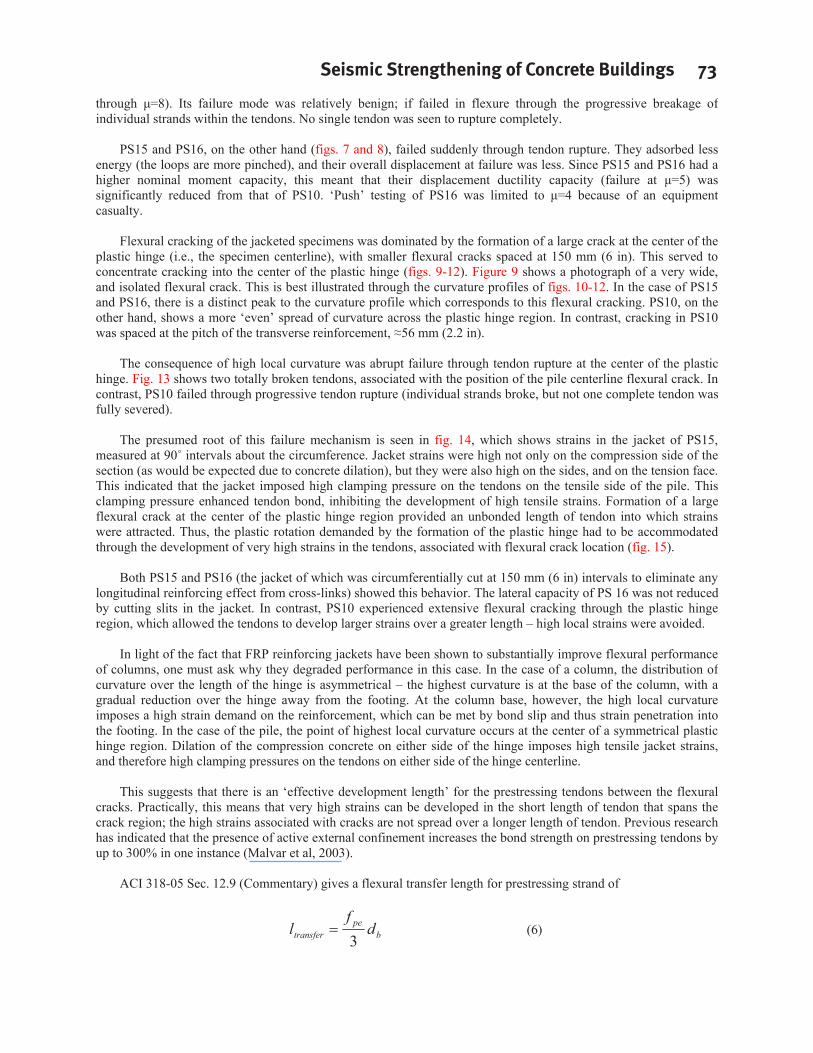
The effect of soil around the pile shaft was modeled by the use of saddle-type load frames (fig. 3A), in which force was applied to the pile through a series of arc-section plates, lined with rubber. The arcs covered 100 of the pile, top and bottom. The top and bottom saddles were connected loosely, so that only the side active in compression would provide confining force. (In the case of specimen PS16, the center actuator was omitted, and the plastic hinge region left unconfined. While external confinement was present adjacent to the hinge region, this method of removing the confining influence on the hinge was validated in a series of solid and hollow prestressed pile tests (Budek and Priestley, 2004, 2005). Fig. 3B shows the moment pattern for a prototype pile-column, indicating the two moment maxima (at the pile head and subgrade) at which hinges could develop. The moment pattern reproduced by the test rig for the point of maximum subgrade moment is shown by reference to the arrows.
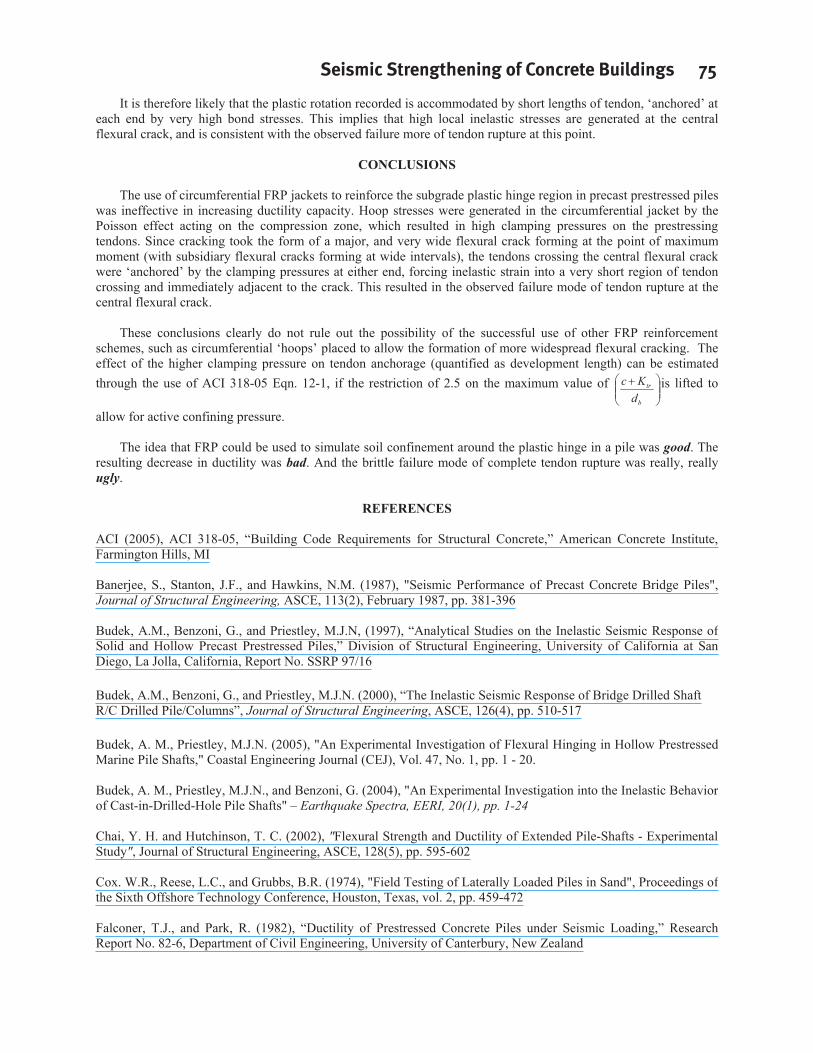
Three specimens were built. These were PS10 – no jacket, external confinement provided over full hinge region PS15 – GFRP jacket applied, external confinement over full hinge region
72 Budek and Benzoni
PS16 – jacket applied and slit circumferentially at 150 mm (6 in) intervals, no external confinement to hinge region
The pile specimens were 610 mm (2 ft) diameter solid round precast prestressed piles, with a pin-to-pin length of 6.1 m (20 ft), and an overall length of 7.315 m (24 ft). They were prestressed using 24 13.2 mm (1/2-in Special) Gr. 270 Lo-Lax tendons (fpu = 1860 MPa (270 ksi)), stressed (after losses) to 1061 MPa (154 ksi). Transverse reinforcement was W6.5 A82 wire (6.53 mm diameter nominal (.257 in)) pitched at 56 mm (2.2 in).
The jackets consisted of seven plies of the TYFO SEH-51 composite system, using TYFO S epoxy and unidirectional E-glass. The main fibers of the E-glass were laid in the transverse direction, as the intention was to provide transverse reinforcement only. Though flexural strength would clearly be enhanced through the jacket’s confinement of a larger core (effectively the full pile section), it was not desired that jacket fibers would act as longitudinal reinforcement (fig. 4).
The jackets were designed by considering the test unit at a midpoint deflection of 180 mm (7.1 in) in specimen PS10. It had similar transverse reinforcement, and tested with external confinement, had failed at a displacement of 187 mm (7.4 in). The total rotation at this point would thus be
059.005.3
180m
mmL
(1)
The measured plastic hinge length for PS10 was 0.903 pile diameters, in which case the curvature is
inmlp
00273.107.0 (2)
The maximum concrete compression strain may thus be found, using a neutral axis depth of 0.2 m (7.9 in) (Priestley et al, 1996)
0214.0'
5.2004.
cc
ujujscu f
f (3)
in which are taken the design values for ultimate jacket stress as fuj=448 MPa, ultimate jacket strain as uj=0.02, and f'cc=62 MPa. Given that somewhat more compression strain might successfully be borne by the pile in the jacketed case, an ultimate value of concrete compression strain cu=0.026 was chosen for design. From the above equation, and the definition of the effective volumetric ratio for a circular jacket retrofit
sjt
D4
(4)
in which tj is the jacket thickness and D the section diameter, the required jacket thickness may be found
)37.0(3.9'004.01.0 inmmf
Dftujuj
cccuj (5)
Seven wraps of unidirectional glass (1.27mm (0.05 in)/wrap) were applied for a total jacket thickness of 9.1 mm (0.36 in). Day-of-test material properties are shown in Table 1. Prestressing tendon strength was not tested due to equipment limitations
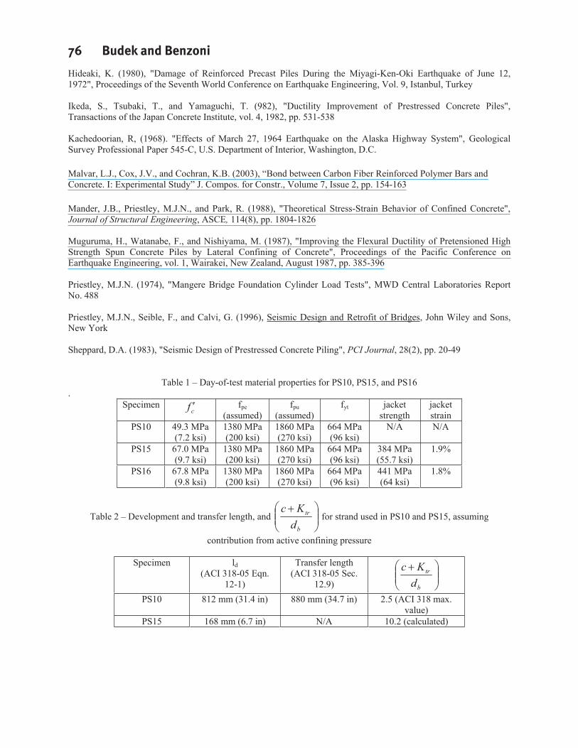
Predictive models were based on a finite-element analysis of the test units, using the Mander model to predict section behavior (Mander et al, 1988). Theoretical moment-curvature curves are shown in fig. 5. The presence of jacketing was expected to give higher flexural strength. PS15 was expected to give higher flexural strength than PS16 until flexural cracking developed in the jacket (the jacket of PS 16 jacket had circumferential cuts as built-in flexural cracks).
Results and Discussion
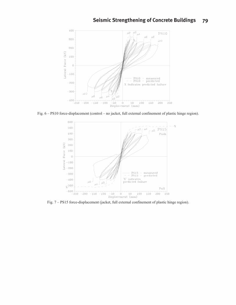
The force-displacement hysteresis loops for the control specimen, PS10 (fig. 6), show a reasonable amount of energy absorption (measured by the width of the hysteresis loops) and high overall ductility (competent performance
Seismic Strengthening of Concrete Buildings 73
through =8). Its failure mode was relatively benign; if failed in flexure through the progressive breakage of individual strands within the tendons. No single tendon was seen to rupture completely.
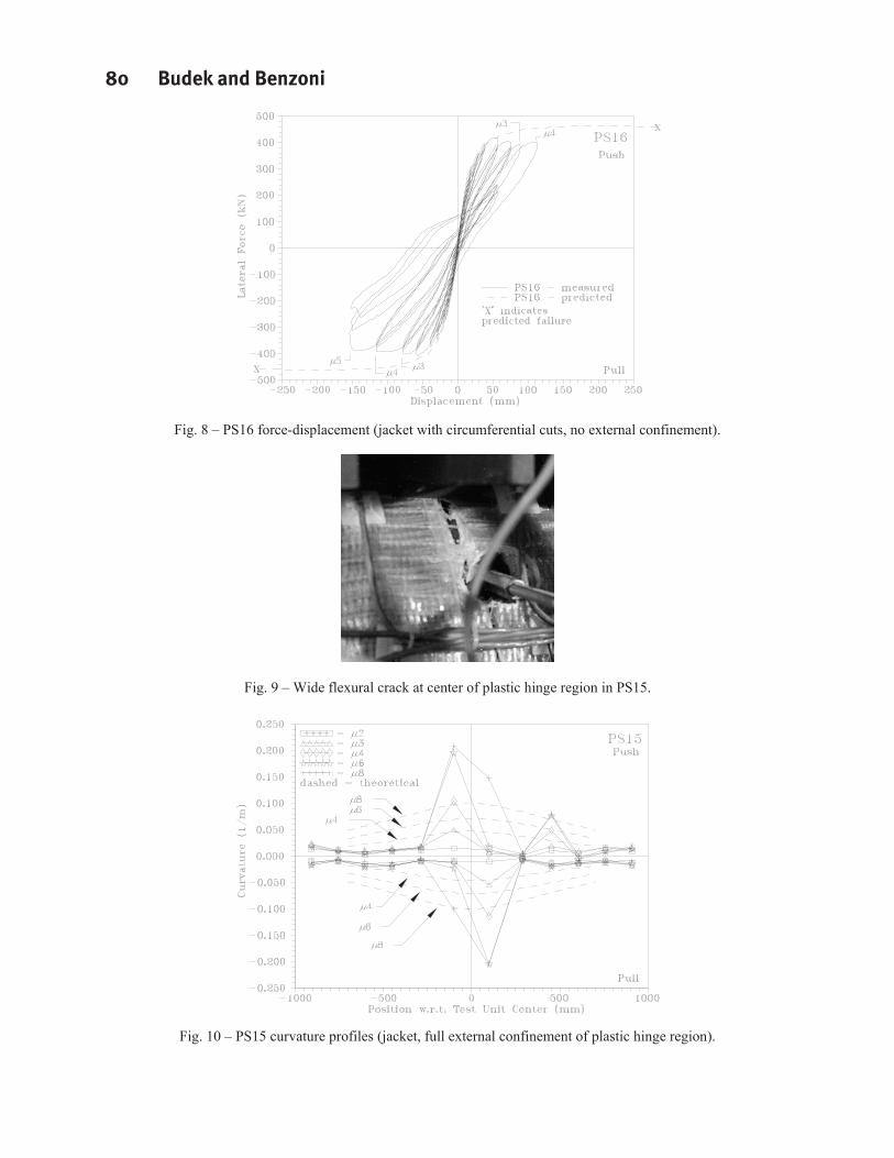
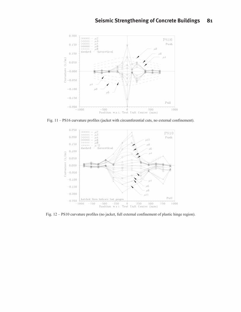
PS15 and PS16, on the other hand (figs. 7 and 8), failed suddenly through tendon rupture. They adsorbed less energy (the loops are more pinched), and their overall displacement at failure was less. Since PS15 and PS16 had a higher nominal moment capacity, this meant that their displacement ductility capacity (failure at =5) was significantly reduced from that of PS10. ‘Push’ testing of PS16 was limited to =4 because of an equipment casualty.
Flexural cracking of the jacketed specimens was dominated by the formation of a large crack at the center of the plastic hinge (i.e., the specimen centerline), with smaller flexural cracks spaced at 150 mm (6 in). This served to concentrate cracking into the center of the plastic hinge (figs. 9-12). Figure 9 shows a photograph of a very wide, and isolated flexural crack. This is best illustrated through the curvature profiles of figs. 10-12. In the case of PS15 and PS16, there is a distinct peak to the curvature profile which corresponds to this flexural cracking. PS10, on the other hand, shows a more ‘even’ spread of curvature across the plastic hinge region. In contrast, cracking in PS10 was spaced at the pitch of the transverse reinforcement, 56 mm (2.2 in).
The consequence of high local curvature was abrupt failure through tendon rupture at the center of the plastic hinge. Fig. 13 shows two totally broken tendons, associated with the position of the pile centerline flexural crack. In contrast, PS10 failed through progressive tendon rupture (individual strands broke, but not one complete tendon was fully severed).
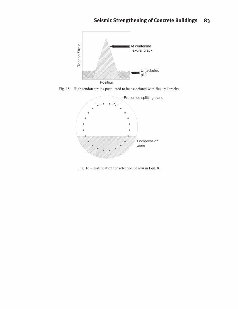
The presumed root of this failure mechanism is seen in fig. 14, which shows strains in the jacket of PS15, measured at 90 intervals about the circumference. Jacket strains were high not only on the compression side of the section (as would be expected due to concrete dilation), but they were also high on the sides, and on the tension face. This indicated that the jacket imposed high clamping pressure on the tendons on the tensile side of the pile. This clamping pressure enhanced tendon bond, inhibiting the development of high tensile strains. Formation of a large flexural crack at the center of the plastic hinge region provided an unbonded length of tendon into which strains were attracted. Thus, the plastic rotation demanded by the formation of the plastic hinge had to be accommodated through the development of very high strains in the tendons, associated with flexural crack location (fig. 15).
Both PS15 and PS16 (the jacket of which was circumferentially cut at 150 mm (6 in) intervals to eliminate any longitudinal reinforcing effect from cross-links) showed this behavior. The lateral capacity of PS 16 was not reduced by cutting slits in the jacket. In contrast, PS10 experienced extensive flexural cracking through the plastic hinge region, which allowed the tendons to develop larger strains over a greater length – high local strains were avoided.
In light of the fact that FRP reinforcing jackets have been shown to substantially improve flexural performance of columns, one must ask why they degraded performance in this case. In the case of a column, the distribution of curvature over the length of the hinge is asymmetrical – the highest curvature is at the base of the column, with a gradual reduction over the hinge away from the footing. At the column base, however, the high local curvature imposes a high strain demand on the reinforcement, which can be met by bond slip and thus strain penetration into the footing. In the case of the pile, the point of highest local curvature occurs at the center of a symmetrical plastic hinge region. Dilation of the compression concrete on either side of the hinge imposes high tensile jacket strains, and therefore high clamping pressures on the tendons on either side of the hinge centerline.
This suggests that there is an ‘effective development length’ for the prestressing tendons between the flexural cracks. Practically, this means that very high strains can be developed in the short length of tendon that spans the crack region; the high strains associated with cracks are not spread over a longer length of tendon. Previous research has indicated that the presence of active external confinement increases the bond strength on prestressing tendons by up to 300% in one instance (Malvar et al, 2003).
ACI 318-05 Sec. 12.9 (Commentary) gives a flexural transfer length for prestressing strand of
bpe
transfer df
l3
(6)

74 Budek and Benzoni
in which fpe is roughly equivalent to the proportional limit of the strand and db the strand diameter. However, it is instructive to use the well-established ACI 318 (ACI, 2005) equation (ACI 318-05 Eqn. 12-1) for development length as a ‘yardstick’:
b
b
tr
set
c
yd d
dKcf
fl
403
(7)
Use of Eqn. 7 for this purpose is justified by the following:
The strand is ‘anchored’ at each end by the longitudinally symmetrical test configuration – the difference between strand stress across the region of interest (i.e., the crack) will change very little, and the stress and strain in the strand will come solely from flexural action across the crack Use of the transfer development length equation in Section 12.9 of ACI 12.9 will yield a similar result for a strand without active confining pressure
The term b
tr
dKc
allows quantification of active confining pressure. The use of an active confining
pressure term is justified by the fact that dilation of the concrete in the compression zone is resisted by external confinement which is ‘mobilized’ by that dilation.
In the term b
tr
dKc
c is the cover thickness, db is the diameter of the bar being developed, and Ktr is the
transverse reinforcement index. This latter term is given (in SI units) by
snfA
K yttrtr 10
(8)
in which Atr is the transverse reinforcement bar area, fyt is the transverse reinforcement yield strength, s is the transverse reinforcement pitch, and n is the number of bars (of those being developed) which cross the presumptive splitting plane. This term assesses the efficiency of the transverse reinforcement in restraining the formation of splitting cracks which will result in debonding of the bars being developed.
ACI 318 places a limitation of 2.5 as a maximum value forb
tr
dKc . However, in the presence of active
confinement it is not unreasonable to examine Eqn. 6 with this restriction removed. Table 2 gives a comparison of development length (using Eqn. 6) with and without active confining pressure, transfer length from ACI 318-05 Sec. 12.9, and
b
tr
dKc for PS10 and PS15 using day-of-test material properties. In this analysis, the value n=4 was
chosen to represent the cracking plane in line with the most highly stressed tendons (fig. 16).
The results of these analyses are interesting, in that the development length calculated using Eqn. 7 is very close to the flexural crack spacing in the jacket. Additionally, the ratios between calculated confining pressures from the steel reinforcement in PS10 and the circumferential jacket applied to PS15 is approximately 4, which is the
approximate ratio between the values of b
tr
dKc . Thus it can be inferred, at least in this case, that
b
tr
dKc
provides a dimensionless indication of the magnitude of the confining pressure beyond the stated limit of 2.5 given by ACI 318-05. These results are also in line with the threefold increase in confining pressure quoted by Malvar et at.
Seismic Strengthening of Concrete Buildings 75
It is therefore likely that the plastic rotation recorded is accommodated by short lengths of tendon, ‘anchored’ at each end by very high bond stresses. This implies that high local inelastic stresses are generated at the central flexural crack, and is consistent with the observed failure more of tendon rupture at this point.
CONCLUSIONS
The use of circumferential FRP jackets to reinforce the subgrade plastic hinge region in precast prestressed piles was ineffective in increasing ductility capacity. Hoop stresses were generated in the circumferential jacket by the Poisson effect acting on the compression zone, which resulted in high clamping pressures on the prestressing tendons. Since cracking took the form of a major, and very wide flexural crack forming at the point of maximum moment (with subsidiary flexural cracks forming at wide intervals), the tendons crossing the central flexural crack were ‘anchored’ by the clamping pressures at either end, forcing inelastic strain into a very short region of tendon crossing and immediately adjacent to the crack. This resulted in the observed failure mode of tendon rupture at the central flexural crack.
These conclusions clearly do not rule out the possibility of the successful use of other FRP reinforcement schemes, such as circumferential ‘hoops’ placed to allow the formation of more widespread flexural cracking. The effect of the higher clamping pressure on tendon anchorage (quantified as development length) can be estimated through the use of ACI 318-05 Eqn. 12-1, if the restriction of 2.5 on the maximum value of
b
tr
dKc is lifted to
allow for active confining pressure.
The idea that FRP could be used to simulate soil confinement around the plastic hinge in a pile was good. The resulting decrease in ductility was bad. And the brittle failure mode of complete tendon rupture was really, really ugly.
REFERENCES
ACI (2005), ACI 318-05, “Building Code Requirements for Structural Concrete,” American Concrete Institute, Farmington Hills, MI
Banerjee, S., Stanton, J.F., and Hawkins, N.M. (1987), "Seismic Performance of Precast Concrete Bridge Piles", Journal of Structural Engineering, ASCE, 113(2), February 1987, pp. 381-396
Budek, A.M., Benzoni, G., and Priestley, M.J.N, (1997), “Analytical Studies on the Inelastic Seismic Response of Solid and Hollow Precast Prestressed Piles,” Division of Structural Engineering, University of California at San Diego, La Jolla, California, Report No. SSRP 97/16
Budek, A.M., Benzoni, G., and Priestley, M.J.N. (2000), “The Inelastic Seismic Response of Bridge Drilled Shaft R/C Drilled Pile/Columns”, Journal of Structural Engineering, ASCE, 126(4), pp. 510-517
Budek, A. M., Priestley, M.J.N. (2005), "An Experimental Investigation of Flexural Hinging in Hollow Prestressed Marine Pile Shafts," Coastal Engineering Journal (CEJ), Vol. 47, No. 1, pp. 1 - 20.
Budek, A. M., Priestley, M.J.N., and Benzoni, G. (2004), "An Experimental Investigation into the Inelastic Behavior of Cast-in-Drilled-Hole Pile Shafts" – Earthquake Spectra, EERI, 20(1), pp. 1-24
Chai, Y. H. and Hutchinson, T. C. (2002), "Flexural Strength and Ductility of Extended Pile-Shafts - Experimental Study", Journal of Structural Engineering, ASCE, 128(5), pp. 595-602
Cox. W.R., Reese, L.C., and Grubbs, B.R. (1974), "Field Testing of Laterally Loaded Piles in Sand", Proceedings of the Sixth Offshore Technology Conference, Houston, Texas, vol. 2, pp. 459-472
Falconer, T.J., and Park, R. (1982), “Ductility of Prestressed Concrete Piles under Seismic Loading,” Research Report No. 82-6, Department of Civil Engineering, University of Canterbury, New Zealand
76 Budek and Benzoni
Hideaki, K. (1980), "Damage of Reinforced Precast Piles During the Miyagi-Ken-Oki Earthquake of June 12, 1972", Proceedings of the Seventh World Conference on Earthquake Engineering, Vol. 9, Istanbul, Turkey
Ikeda, S., Tsubaki, T., and Yamaguchi, T. (982), "Ductility Improvement of Prestressed Concrete Piles", Transactions of the Japan Concrete Institute, vol. 4, 1982, pp. 531-538
Kachedoorian, R, (1968). "Effects of March 27, 1964 Earthquake on the Alaska Highway System", Geological Survey Professional Paper 545-C, U.S. Department of Interior, Washington, D.C.
Malvar, L.J., Cox, J.V., and Cochran, K.B. (2003), “Bond between Carbon Fiber Reinforced Polymer Bars and Concrete. I: Experimental Study” J. Compos. for Constr., Volume 7, Issue 2, pp. 154-163
Mander, J.B., Priestley, M.J.N., and Park, R. (1988), "Theoretical Stress-Strain Behavior of Confined Concrete", Journal of Structural Engineering, ASCE, 114(8), pp. 1804-1826
Muguruma, H., Watanabe, F., and Nishiyama, M. (1987), "Improving the Flexural Ductility of Pretensioned High Strength Spun Concrete Piles by Lateral Confining of Concrete", Proceedings of the Pacific Conference on Earthquake Engineering, vol. 1, Wairakei, New Zealand, August 1987, pp. 385-396
Priestley, M.J.N. (1974), "Mangere Bridge Foundation Cylinder Load Tests", MWD Central Laboratories Report No. 488
Priestley, M.J.N., Seible, F., and Calvi, G. (1996), Seismic Design and Retrofit of Bridges, John Wiley and Sons, New York
Sheppard, D.A. (1983), "Seismic Design of Prestressed Concrete Piling", PCI Journal, 28(2), pp. 20-49
Table 1 – Day-of-test material properties for PS10, PS15, and PS16 .
Specimen cf fpe
(assumed) fpu
(assumed) fyt jacket
strengthjacketstrain
PS10 49.3 MPa (7.2 ksi)
1380 MPa (200 ksi)
1860 MPa (270 ksi)
664 MPa (96 ksi)
N/A N/A
PS15 67.0 MPa (9.7 ksi)
1380 MPa (200 ksi)
1860 MPa (270 ksi)
664 MPa (96 ksi)
384 MPa (55.7 ksi)
1.9%
PS16 67.8 MPa (9.8 ksi)
1380 MPa (200 ksi)
1860 MPa (270 ksi)
664 MPa (96 ksi)
441 MPa (64 ksi)
1.8%
Table 2 – Development and transfer length, and b
tr
dKc
for strand used in PS10 and PS15, assuming
contribution from active confining pressure
Specimen ld(ACI 318-05 Eqn.
12-1)
Transfer length (ACI 318-05 Sec.
12.9) b
tr
dKc
PS10 812 mm (31.4 in) 880 mm (34.7 in) 2.5 (ACI 318 max. value)
PS15 168 mm (6.7 in) N/A 10.2 (calculated)

Seismic Strengthening of Concrete Buildings 77
Fig. 1- Column FRP flexural retrofit.
Fig. 2 – Pile Test Rig.
78 Budek and Benzoni
(A) (B) Fig. 3 – Saddles to apply external confinement (A), and moment pattern reproduced (B) between points of inflection
(arrows).
Fig. 4– PS15 and PS16 GFRP jacket configuration.
Fig. 5 – Theoretical moment-curvature relationship for PS10, PS15, and PS16.
Seismic Strengthening of Concrete Buildings 79
Fig. 6 – PS10 force-displacement (control – no jacket, full external confinement of plastic hinge region).
Fig. 7 – PS15 force-displacement (jacket, full external confinement of plastic hinge region).
80 Budek and Benzoni
Fig. 8 – PS16 force-displacement (jacket with circumferential cuts, no external confinement).
Fig. 9 – Wide flexural crack at center of plastic hinge region in PS15.
Fig. 10 – PS15 curvature profiles (jacket, full external confinement of plastic hinge region).
Seismic Strengthening of Concrete Buildings 81
Fig. 11 – PS16 curvature profiles (jacket with circumferential cuts, no external confinement).
Fig. 12 – PS10 curvature profiles (no jacket, full external confinement of plastic hinge region).
82 Budek and Benzoni
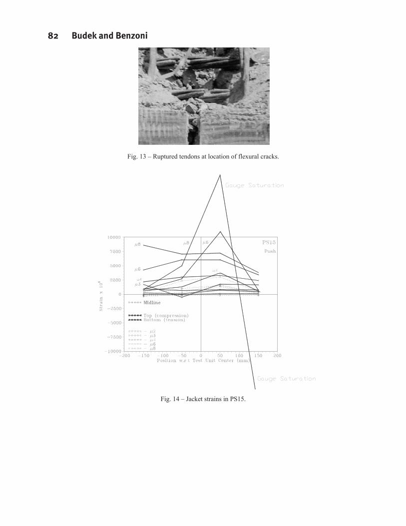
Fig. 13 – Ruptured tendons at location of flexural cracks.
Fig. 14 – Jacket strains in PS15.
Seismic Strengthening of Concrete Buildings 83
PositionTe
ndon
Stra
in
Unjacketedpile
At centerlineflexural crack
Fig. 15 – High tendon strains postulated to be associated with flexural cracks.
Presumed splitting plane
Compressionzone
Fig. 16 – Justification for selection of n=4 in Eqn. 8.

84 Budek and Benzoni
Related Documents