I J C T A, 9(14) 2016, pp. 6449-6454 © International Science Press Protocol Design for Hybrid Visible Light Communication (VLC) and RF Communication in Indoor Environment Kaveti Sasideep * and S. Krithiga ** ABSTRACT This paper introduce the concept of “visible light” for an enabling technologyin indoor environment. Over the years many different strategies and technologies have been proposed for communication and bidirectional data transfer. Visible light communication (VLC) uses a immense unregulated and free light spectrum. It is considered to be a solution as overcome the crowded radio spectrum as wireless communication systems. However, duplex communication, user mobility, and handover mechanisms are becoming ambitious tasks in a VLC system. This project proposes a hybrid network model of VLC and RF in which the VLC channel is only used for downlink transmission. I. INTRODUCTION For any communication, a communication medium like a wire or Radio Frequencies is required. With conventional radio frequency (RF) communication bandwidth becoming more and more crowded by existing wireless communication technologies like Wi-Fi, Bluetooth etc.hence there is a need for new communication technology that does not require RF. Visible Light Communication (VLC) is fast emerging technology that can serve as an alternative to many wireless communication technologies [1]. Instead of having a separate medium such as wires or radio frequency the project proposes to have visible light as medium. VLC uses optical communication, it has many inherent advantages over RF technologies. VLC is capable of higher bandwidths than RF technologies. VLC does not cause any radiation exposure hazards. VLC is also immune to electromagnetic interference and hence can be used in applications where most RF technologies cannot be used like inside aircrafts and industries [2].Unlike other optical technologies like IR, VLC involves visible light spectrum and can be implemented with our ordinary light source itself[3]. Thin-film high-power phosphorescent white LED used as VLC[4]. This system will enable high quality of service by the high radiation power from this lighting equipment. And, this system does not cause or suffer from radio or electromagnetic interference [5].Optical wireless was limited for a longtime due to insufficient optical power Recently, low-cost high-power LEDsare available using infrared andvisible lightfor data transmission, LED can bemodulated at high speed Flicker is not visible[6] II. DESCRIPTION OF PROPOSED SYSTEM The proposed system uses visible light as a medium of communication. LED lamps as used for data transmission instead of separate transmitters. The design of a VLC bridge circuitry that performs bidirectional data transfer between PCs has been proposed in this work. * Departmentof Electronics and Communication engineeringSRMUniversityKancheepuram, India, E-mail: [email protected] ** Assistant Professor Department of Electronics and CommunicationEngineering SRM University, Kancheepuram, India, E-mail: [email protected]

Welcome message from author
This document is posted to help you gain knowledge. Please leave a comment to let me know what you think about it! Share it to your friends and learn new things together.
Transcript

I J C T A, 9(14) 2016, pp. 6449-6454© International Science Press
Protocol Design for Hybrid Visible LightCommunication (VLC) and RFCommunication in Indoor EnvironmentKaveti Sasideep* and S. Krithiga**
ABSTRACT
This paper introduce the concept of “visible light” for an enabling technologyin indoor environment. Over the yearsmany different strategies and technologies have been proposed for communication and bidirectional data transfer.Visible light communication (VLC) uses a immense unregulated and free light spectrum. It is considered to be asolution as overcome the crowded radio spectrum as wireless communication systems. However, duplex communication,user mobility, and handover mechanisms are becoming ambitious tasks in a VLC system. This project proposes ahybrid network model of VLC and RF in which the VLC channel is only used for downlink transmission.
I. INTRODUCTION
For any communication, a communication medium like a wire or Radio Frequencies is required. Withconventional radio frequency (RF) communication bandwidth becoming more and more crowded by existingwireless communication technologies like Wi-Fi, Bluetooth etc.hence there is a need for new communicationtechnology that does not require RF. Visible Light Communication (VLC) is fast emerging technology thatcan serve as an alternative to many wireless communication technologies [1].
Instead of having a separate medium such as wires or radio frequency the project proposes to havevisible light as medium.
VLC uses optical communication, it has many inherent advantages over RF technologies. VLC is capableof higher bandwidths than RF technologies. VLC does not cause any radiation exposure hazards. VLC isalso immune to electromagnetic interference and hence can be used in applications where most RFtechnologies cannot be used like inside aircrafts and industries [2].Unlike other optical technologies likeIR, VLC involves visible light spectrum and can be implemented with our ordinary light source itself[3].
Thin-film high-power phosphorescent white LED used as VLC[4]. This system will enable high qualityof service by the high radiation power from this lighting equipment. And, this system does not cause orsuffer from radio or electromagnetic interference [5].Optical wireless was limited for a longtime due toinsufficient optical power Recently, low-cost high-power LEDsare available using infrared andvisible lightfordata transmission, LED can bemodulated at high speed Flicker is not visible[6]
II. DESCRIPTION OF PROPOSED SYSTEM
The proposed system uses visible light as a medium of communication. LED lamps as used for datatransmission instead of separate transmitters. The design of a VLC bridge circuitry that performs bidirectionaldata transfer between PCs has been proposed in this work.
* Departmentof Electronics and Communication engineeringSRMUniversityKancheepuram, India, E-mail: [email protected]** Assistant Professor Department of Electronics and CommunicationEngineering SRM University, Kancheepuram, India, E-mail:

6450 Kaveti Sasideep and S. Krithiga
The block diagram of proposed VLC transmitter is shown in Figure 1.
Figure 1: VLC Transmitter
Visual Basic program has been coded to handle connection and data transfer between VLC hardwareand PC through USB interface.
The block diagram of proposed VLC receiver is shown in Figure 2.
Figure 2: VLC Receiver
Protocol Design for Hybrid Visible Light Communication (VLC) and RF Communication... 6451
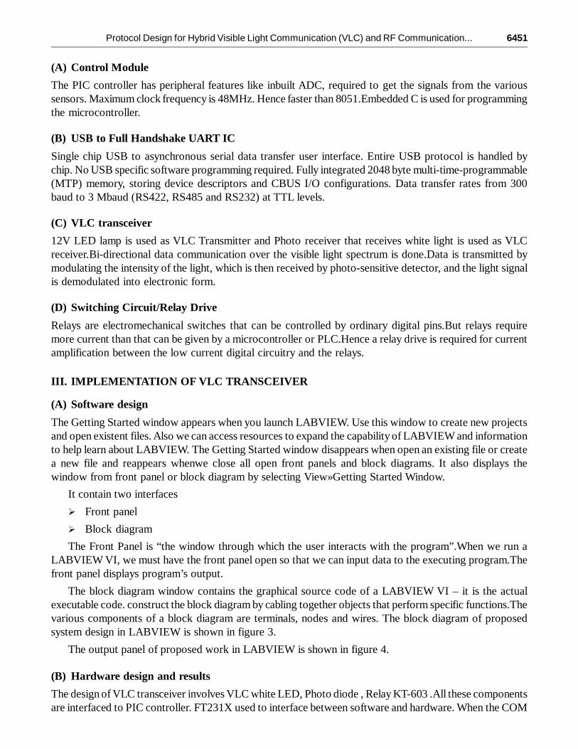
(A) Control Module
The PIC controller has peripheral features like inbuilt ADC, required to get the signals from the varioussensors. Maximum clock frequency is 48MHz. Hence faster than 8051.Embedded C is used for programmingthe microcontroller.
(B) USB to Full Handshake UART IC
Single chip USB to asynchronous serial data transfer user interface. Entire USB protocol is handled bychip. No USB specific software programming required. Fully integrated 2048 byte multi-time-programmable(MTP) memory, storing device descriptors and CBUS I/O configurations. Data transfer rates from 300baud to 3 Mbaud (RS422, RS485 and RS232) at TTL levels.
(C) VLC transceiver
12V LED lamp is used as VLC Transmitter and Photo receiver that receives white light is used as VLCreceiver.Bi-directional data communication over the visible light spectrum is done.Data is transmitted bymodulating the intensity of the light, which is then received by photo-sensitive detector, and the light signalis demodulated into electronic form.
(D) Switching Circuit/Relay Drive
Relays are electromechanical switches that can be controlled by ordinary digital pins.But relays requiremore current than that can be given by a microcontroller or PLC.Hence a relay drive is required for currentamplification between the low current digital circuitry and the relays.
III. IMPLEMENTATION OF VLC TRANSCEIVER
(A) Software design
The Getting Started window appears when you launch LABVIEW. Use this window to create new projectsand open existent files. Also we can access resources to expand the capability of LABVIEW and informationto help learn about LABVIEW. The Getting Started window disappears when open an existing file or createa new file and reappears whenwe close all open front panels and block diagrams. It also displays thewindow from front panel or block diagram by selecting View»Getting Started Window.
It contain two interfaces
� Front panel
� Block diagram
The Front Panel is “the window through which the user interacts with the program”.When we run aLABVIEW VI, we must have the front panel open so that we can input data to the executing program.Thefront panel displays program’s output.
The block diagram window contains the graphical source code of a LABVIEW VI – it is the actualexecutable code. construct the block diagram by cabling together objects that perform specific functions.Thevarious components of a block diagram are terminals, nodes and wires. The block diagram of proposedsystem design in LABVIEW is shown in figure 3.
The output panel of proposed work in LABVIEW is shown in figure 4.
(B) Hardware design and results
The design of VLC transceiver involves VLC white LED, Photo diode , Relay KT-603 .All these componentsare interfaced to PIC controller. FT231X used to interface between software and hardware. When the COM

6452 Kaveti Sasideep and S. Krithiga
Figure 4: Output panel of proposed work in LAB VIEW
Figure 3: Block diagram design in LAB VIEW
Protocol Design for Hybrid Visible Light Communication (VLC) and RF Communication... 6453
16 is entered in the Port Number and ON the port then communication between the hardware and softwarestarted
In an LED light bulb, a constant current is applied which produces a constant stream of photons that areemitted from the bulb which is observed as visible light. When the current is varied slowly the outputintensity of the light dims up and down.The optical output is modulated at extremely high speeds by varyingthe current and is detected by a photo-detector device and converted back to electrical voltage. Due to itshigh speed the intensity modulation is imperceptible to the human eye.the hardware implementation ofVLC transmitter is shown in figure 5.
Figure 5: Hardware implementation of VLC transmitter
The 3 relays ON on the control panel is shown in figure 6
Figure 6: 3 relays ON on the control panel

6454 Kaveti Sasideep and S. Krithiga
All the 3 relays are ON in hardware implementation is shown in figure 7
Figure 7: All the 3 relays are ON in hardware implementation
IV. CONCLUSION
This proposed model can be used in bandwidth constrained places and in places fear of electromagneticinterference such as aircrafts and industries. Also this model providesIncreased Data density and moresecurity withLess ecological impact
ACKNOWLEDGMENTThe authors are grateful to the HOD and faculty members of department of ECE for their encouragement and guidance topresent/publish the paper
REFERENCES
[1] D. Tsonev et al., “A 3-Gb/s single- LED OFDM-based wireless VLC linkusing a gallium nitride ìLED,” IEEE Photon.Technol. Lett., vol. 26, no. 7, pp. 637–640, Apr. 1, 2014.
[2] Y. Wang et al., “875-Mb/s asynchronous bi-directional 64QAM-OFDM SCM-WDM transmission over RGB-LED-basedvisible light communication system,” in Proc. Opt. Fiber Commun. Conf. Expo. Opt. Eng., Mar. 2013, pp. 1–3.
[3] Y. Wang et al., “Demonstration of 575-Mb/s downlink and 225-Mb/s uplink bi-directional visible light communicationusing RGB LED and phosphor-based LED,” vol. 21, no. 1, pp. 1203–1208, Jan. 2013.
[4] J. Vucic et al., “513 Mbit/s visible light communications link based on DMT-modulation of a white LED,” J. Lightw.Technol.,pp. 3512–3518, Dec. 15, 2010.
[5] T. Komine and M. Nakagawa, “Integrated system of white LED visiblelight communication and power-line communication,”IEEE Trans. Consum. Electron., vol. 49, no. 1, pp. 71–79, Feb. 2003.
[6] L. Grobe et al., “High-speed visible light communication systems,” IEEE Commun. Mag., vol. 51, no. 12, pp. 60–66, Dec.2013.
Related Documents