PROTEUS PREMIX CONDENSING BOILER PROTEUS PREMIX PPR 24/28/30/35 HM/HCH/HST INSTALLATION AND USER'S OPERATING INSTRUCTIONS

Welcome message from author
This document is posted to help you gain knowledge. Please leave a comment to let me know what you think about it! Share it to your friends and learn new things together.
Transcript
PROTEUS PREMIXCONDENSING BOILER
PROTEUS PREMIX PPR 24/28/30/35 HM/HCH/HST
INSTALLATION AND USER'S OPERATING INSTRUCTIONS

INTRODUCTION
1 - INTRODUCTION .................................................................................................................................. 3 2- GUARANTEE AND SERVICE .................................................................................................................. 3 3- DEFINITIONS OF SYMBOLS .................................................................................................................. 3 4- SAFETY RULES AND WARNINGS .......................................................................................................... 4 5- PRODUCT ............................................................................................................................................. 5
5.1- General Specifications .................................................................................................................. 5
5.2- Notations of Product .................................................................................................................... 5
5.3- Detailed View and List of Components ........................................................................................ 6
5.4- Technical Specifications ............................................................................................................... 9
5.5- Electrical Drawing ....................................................................................................................... 12
6. BOILER PACKAGING ........................................................................................................................... 13 7. FLUES ................................................................................................................................................. 14
7.1- Flue Sizes .................................................................................................................................... 14
7.2- Flue Types ................................................................................................................................... 14
7.3- Distances for Placement of Flues ............................................................................................... 15
8- INSTALLATION ................................................................................................................................... 16 8.1- Selection of Installation Location of Device ............................................................................... 16
8.2- Independent Operation from Ambient Air (Type C) .................................................................. 17
8.3- Mounting the Boiler ................................................................................................................... 17
9 - CONNECTIONS .................................................................................................................................. 18 9.1- Condensate Discharge Connection ............................................................................................ 18
9.2- Gas and Water Connections ....................................................................................................... 19
9.3- Electrical Connection .................................................................................................................. 20
9.4- Room Thermostat ...................................................................................................................... 21
9.5- Outdoor Sensor .......................................................................................................................... 22
9.6- Room Thermostat and Outer Air Sensor Connection ................................................................ 23
9.7- Controller Connection ................................................................................................................ 23
10- COMMISSIONING, USE AND TURNING OFF THE BOILER ................................................................ 24 11-CONTROL PANEL .............................................................................................................................. 25 12- GAS CONVERSION ........................................................................................................................... 28 13- ERROR CODES VE DESCRIPTIONS .................................................................................................... 28 14- USEFULL INFORMATION ON PRODUCT ........................................................................................... 31 15- ANNEXES ......................................................................................................................................... 33 16- WALL MOUNTING TEMPLATE…………………………………………………………………………………………………….. 34

1 – INTRODUCTION
First of all, we would like to thank you for choosing E.C.A brand.
E.C.A. Proteus Premix condensing boilers have been designed for an efficient, safe and comfortable centralheating and hot water requirement. The Proteus Premix condensing boilers can possibly use natural gas or LPGaccording to the desired fuel preference.
HM Model: It is designed for both Central Heating (CH) and Domestic Hot Water (DHW).
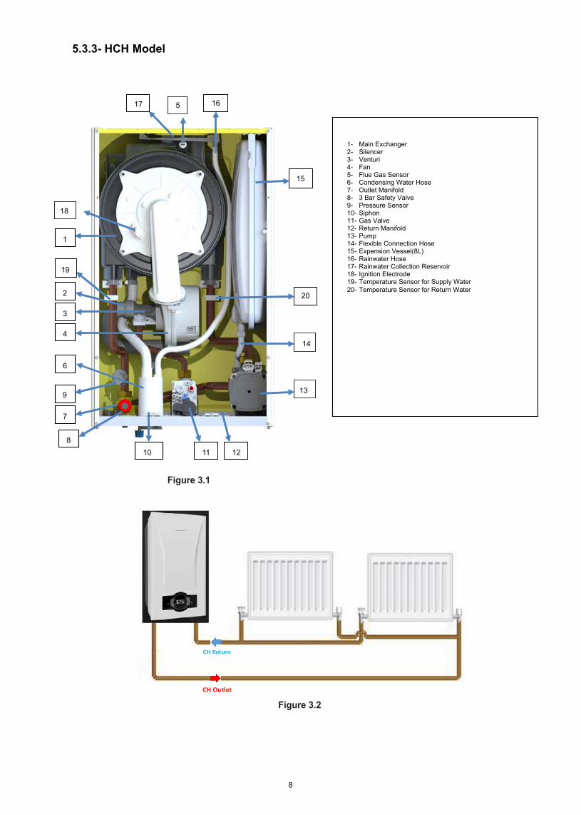
HCH Model: It is designed for Central Heating (CH).
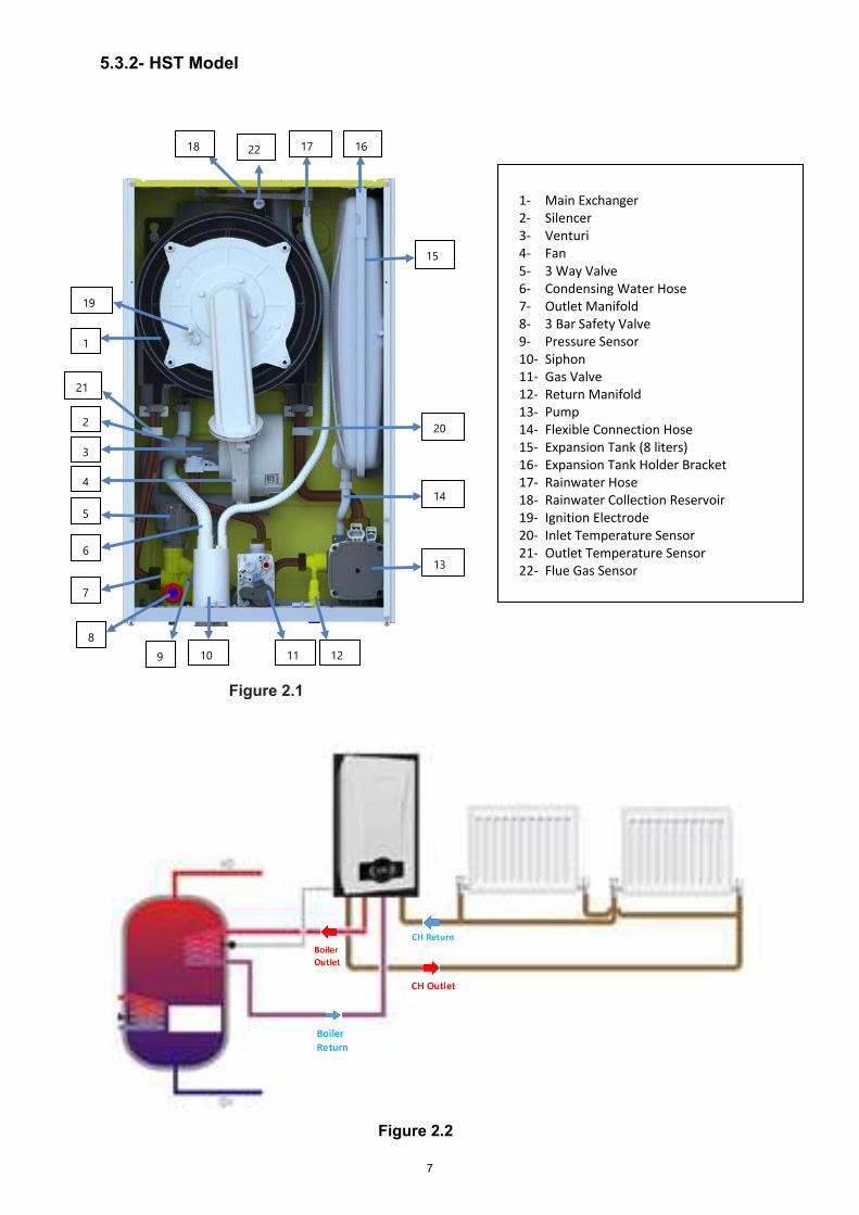
HST Model: It is designed for both Central Heating (CH) and Domestic Hot Water (DHW). Boiler connection must be used for Domestic Hot Water (DHW) requirement.
The assembly and usage information of 24/28/30/35 kW Proteus Premix condensing boilers are available in this manual. Detailed information have been provided in the guide regarding the technical specifications of the devices, selection of the boiler location, fitting its water, gas, flue and electric supply connections, gas conversion, maintenance information and resolution of possible failures. Please carefully read the manual in order to benefit from all the features of your device.
Keep all the documents provided by your device in order to refer when required.
2- GUARANTEE AND SERVICE
• The appliance has guarantee period against faulty workmanship or material in condition that the instructionsand precautions in this manual must be obeyed. The service operations and general maintenance must becarried out only qualified person.
• The warranty certificate must be registered by Service in the installation day.
• Your appliance needs not any repairs if operated according to this manual. For assistance for additionalinformation, consult qualified person, installer or gas supplier.
3- DEFINITIONS OF SYMBOLS
The following symbols have been placed at required points in the text in order to draw attention to significant points regarding the usage and assembly of the device. The meanings of the symbols have been specified below.
Indicates that the situation that can only be interfered by qualified person.
Explanations containing information that should be considered by the user.
CAUTION:It means that you may suffer from material damage or slight personal injury.
DANGER: It means that you may suffer from sever personal injury.
3
4- SAFETY RULES AND WARNINGS
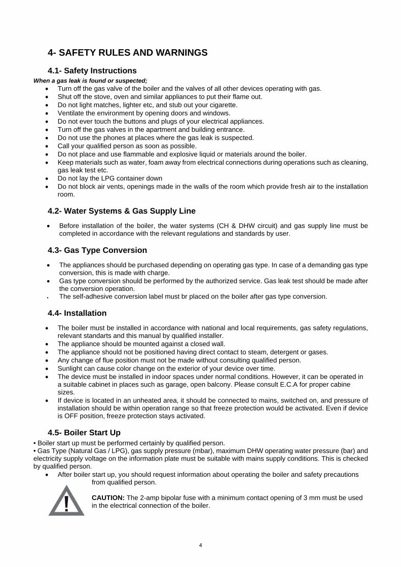
4.1- Safety InstructionsWhen a gas leak is found or suspected;
• Turn off the gas valve of the boiler and the valves of all other devices operating with gas.• Shut off the stove, oven and similar appliances to put their flame out.• Do not light matches, lighter etc, and stub out your cigarette.• Ventilate the environment by opening doors and windows.• Do not ever touch the buttons and plugs of your electrical appliances.• Turn off the gas valves in the apartment and building entrance.• Do not use the phones at places where the gas leak is suspected.• Call your qualified person as soon as possible.• Do not place and use flammable and explosive liquid or materials around the boiler.• Keep materials such as water, foam away from electrical connections during operations such as cleaning,
gas leak test etc.• Do not lay the LPG container down• Do not block air vents, openings made in the walls of the room which provide fresh air to the installation
room.
4.2- Water Systems & Gas Supply Line • Before installation of the boiler, the water systems (CH & DHW circuit) and gas supply line must be
completed in accordance with the relevant regulations and standards by user.
4.3- Gas Type Conversion • The appliances should be purchased depending on operating gas type. In case of a demanding gas type
conversion, this is made with charge.• Gas type conversion should be performed by the authorized service. Gas leak test should be made after
the conversion operation.• The self-adhesive conversion label must br placed on the boiler after gas type conversion.
4.4- Installation • The boiler must be installed in accordance with national and local requirements, gas safety regulations,
relevant standarts and this manual by qualified installer.• The appliance should be mounted against a closed wall.• The appliance should not be positioned having direct contact to steam, detergent or gases.• Any change of flue position must not be made without consulting qualified person.• Sunlight can cause color change on the exterior of your device over time.• The device must be installed in indoor spaces under normal conditions. However, it can be operated in
a suitable cabinet in places such as garage, open balcony. Please consult E.C.A for proper cabinesizes.
• If device is located in an unheated area, it should be connected to mains, switched on, and pressure ofinstallation should be within operation range so that freeze protection would be activated. Even if deviceis OFF position, freeze protection stays activated.
4.5- Boiler Start Up • Boiler start up must be performed certainly by qualified person.• Gas Type (Natural Gas / LPG), gas supply pressure (mbar), maximum DHW operating water pressure (bar) andelectricity supply voltage on the information plate must be suitable with mains supply conditions. This is checkedby qualified person.
• After boiler start up, you should request information about operating the boiler and safety precautionsfrom qualified person.
CAUTION: The 2-amp bipolar fuse with a minimum contact opening of 3 mm must be used in the electrical connection of the boiler.
4
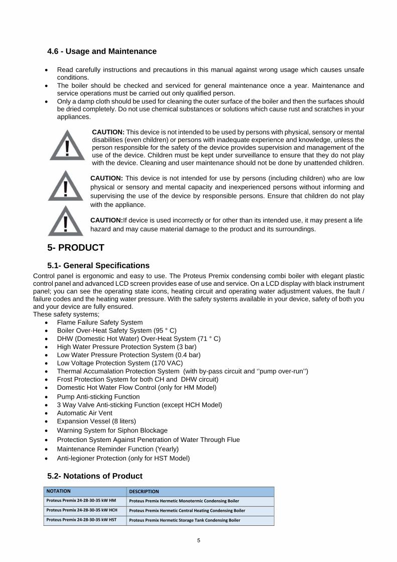
4.6 - Usage and Maintenance
• Read carefully instructions and precautions in this manual against wrong usage which causes unsafeconditions.
• The boiler should be checked and serviced for general maintenance once a year. Maintenance andservice operations must be carried out only qualified person.
• Only a damp cloth should be used for cleaning the outer surface of the boiler and then the surfaces shouldbe dried completely. Do not use chemical substances or solutions which cause rust and scratches in yourappliances.
CAUTION: This device is not intended to be used by persons with physical, sensory or mental disabilities (even children) or persons with inadequate experience and knowledge, unless the person responsible for the safety of the device provides supervision and management of the use of the device. Children must be kept under surveillance to ensure that they do not play with the device. Cleaning and user maintenance should not be done by unattended children.
CAUTION: This device is not intended for use by persons (including children) who are low physical or sensory and mental capacity and inexperienced persons without informing and supervising the use of the device by responsible persons. Ensure that children do not play with the appliance.
CAUTION:If device is used incorrectly or for other than its intended use, it may present a life hazard and may cause material damage to the product and its surroundings.
5- PRODUCT
5.1- General SpecificationsControl panel is ergonomic and easy to use. The Proteus Premix condensing combi boiler with elegant plastic control panel and advanced LCD screen provides ease of use and service. On a LCD display with black instrument panel; you can see the operating state icons, heating circuit and operating water adjustment values, the fault / failure codes and the heating water pressure. With the safety systems available in your device, safety of both you and your device are fully ensured. These safety systems;
• Flame Failure Safety System• Boiler Over-Heat Safety System (95 ° C)• DHW (Domestic Hot Water) Over-Heat System (71 ° C)• High Water Pressure Protection System (3 bar)• Low Water Pressure Protection System (0.4 bar)• Low Voltage Protection System (170 VAC)• Thermal Accumalation Protection System (with by-pass circuit and ‘’pump over-run’’)• Frost Protection System for both CH and DHW circuit)• Domestic Hot Water Flow Control (only for HM Model)• Pump Anti-sticking Function• 3 Way Valve Anti-sticking Function (except HCH Model)• Automatic Air Vent• Expansion Vessel (8 liters)• Warning System for Siphon Blockage• Protection System Against Penetration of Water Through Flue• Maintenance Reminder Function (Yearly)• Anti-legioner Protection (only for HST Model)
5.2- Notations of Product NOTATION DESCRIPTION
Proteus Premix 24-28-30-35 kW HM Proteus Premix Hermetic Monotermic Condensing Boiler
Proteus Premix 24-28-30-35 kW HCH Proteus Premix Hermetic Central Heating Condensing Boiler
Proteus Premix 24-28-30-35 kW HST Proteus Premix Hermetic Storage Tank Condensing Boiler
5
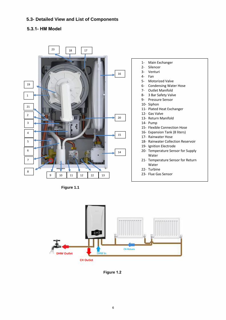
5.3- Detailed View and List of Components
Figure 1.1
1- Main Exchanger2- Silencer3- Venturi4- Fan5- Motorized Valve6- Condensing Water Hose7- Outlet Manifold8- 3 Bar Safety Valve9- Pressure Sensor10- Siphon11- Plated Heat Exchanger12- Gas Valve13- Return Manifold14- Pump15- Flexible Connection Hose16- Expansion Tank (8 liters)17- Rainwater Hose18- Rainwater Collection Reservoir19- Ignition Electrode20- Temperature Sensor for Supply
Water21- Temperature Sensor for Return
Water22- Turbine23- Flue Gas Sensor
18 17
8
7
6
5
4
3
2
16
1
11 12 13
14
15
9 10
19
20
21
22
23
5.3.1- HM Model
Figure 1.2
6
18 17
8
7
6
5
4
3
2
15
16
1
11 12
13
14
9 10
19
20
22
21
Figure 2.1
5.3.2- HST Model
Figure 2.2
1- Main Exchanger2- Silencer3- Venturi4- Fan5- 3 Way Valve6- Condensing Water Hose7- Outlet Manifold8- 3 Bar Safety Valve9- Pressure Sensor10- Siphon11- Gas Valve12- Return Manifold13- Pump14- Flexible Connection Hose15- Expansion Tank (8 liters)16- Expansion Tank Holder Bracket17- Rainwater Hose18- Rainwater Collection Reservoir19- Ignition Electrode20- Inlet Temperature Sensor21- Outlet Temperature Sensor22- Flue Gas Sensor
7
17 16
8
7
6
4
3
2
15
1
11 12
13
14
9
10
1- Main Exchanger2- Silencer3- Venturi4- Fan5- Flue Gas Sensor6- Condensing Water Hose7- Outlet Manifold8- 3 Bar Safety Valve9- Pressure Sensor10- Siphon11- Gas Valve12- Return Manifold13- Pump14- Flexible Connection Hose15- Expension Vessel(8L)16- Rainwater Hose17- Rainwater Collection Reservoir18- Ignition Electrode19- Temperature Sensor for Supply Water20- Temperature Sensor for Return Water
18
20
5
19
Figure 3.1
5.3.3- HCH Model
Figure 3.2
8
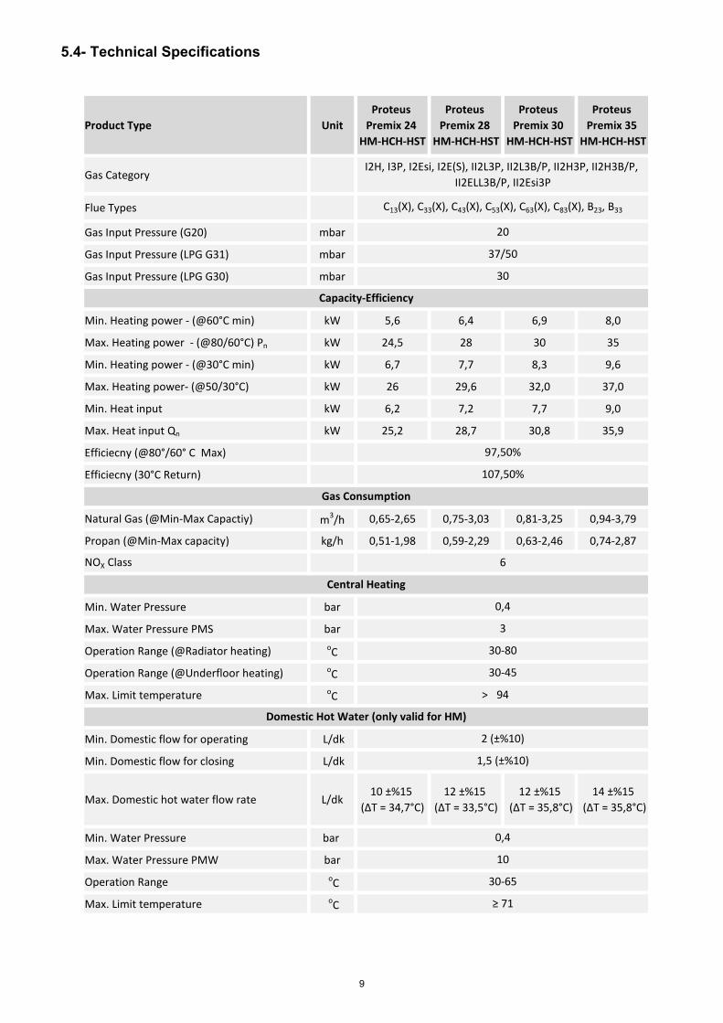
5.4- Technical Specifications
Product Type UnitProteus
Premix 24 HM-HCH-HST
Proteus Premix 28
HM-HCH-HST
Proteus Premix 30
HM-HCH-HST
Proteus Premix 35
HM-HCH-HST
Gas Category
Flue Types
Gas Input Pressure (G20) mbar
Gas Input Pressure (LPG G31) mbar
Gas Input Pressure (LPG G30) mbar
Min. Heating power - (@60°C min) kW 5,6 6,4 6,9 8,0
Max. Heating power - (@80/60°C) Pn kW 24,5 28 30 35
Min. Heating power - (@30°C min) kW 6,7 7,7 8,3 9,6
Max. Heating power- (@50/30°C) kW 26 29,6 32,0 37,0
Min. Heat input kW 6,2 7,2 7,7 9,0
Max. Heat input Qn kW 25,2 28,7 30,8 35,9
Efficiecny (@80°/60° C Max)
Efficiecny (30°C Return)
Natural Gas (@Min-Max Capactiy) m3/h 0,65-2,65 0,75-3,03 0,81-3,25 0,94-3,79
Propan (@Min-Max capacity) kg/h 0,51-1,98 0,59-2,29 0,63-2,46 0,74-2,87
NOX Class
Min. Water Pressure bar
Max. Water Pressure PMS bar
Operation Range (@Radiator heating) oC
Operation Range (@Underfloor heating) oC
Max. Limit temperature oC
Min. Domestic flow for operating L/dk
Min. Domestic flow for closing L/dk
Max. Domestic hot water flow rate L/dk 10 ±%15
(ΔT = 34,7°C)12 ±%15
(ΔT = 33,5°C)12 ±%15
(ΔT = 35,8°C)14 ±%15
(ΔT = 35,8°C)
Min. Water Pressure bar
Max. Water Pressure PMW bar
Operation Range oC
Max. Limit temperature oC
10
30-65
≥ 71
> 94
Domestic Hot Water (only valid for HM)
2 (±%10)
1,5 (±%10)
0,4
Central Heating
0,4
3
30-80
30-45
Capacity-Efficiency
97,50%
107,50%
Gas Consumption
6
I2H, I3P, I2Esi, I2E(S), II2L3P, II2L3B/P, II2H3P, II2H3B/P, II2ELL3B/P, II2Esi3P
C13(X), C33(X), C43(X), C53(X), C63(X), C83(X), B23, B33
20
37/50
30
9
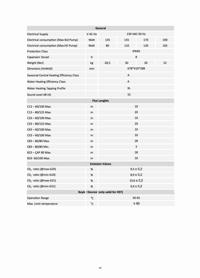
Electrical Supply
Electrical consumption (Max-Std Pump)
Electrical consumption (Max-HE Pump)
Protection eıass
Expansion Vessel
Weight (Net)
Dimesions (HxWxD)
Seasonal eentral Heating Efficiency eıass
Water Heating Efficiency eıass
Water Heating Tapping Profile
Sound Level dB (A)
e13 - 60/100 Max.
e13 - 80/125 Max.
e33 - 60/100 Max.
e33 - 80/125 Max.
e43 - 60/100 Max.
e53 - 60/100 Max.
e83 - 80/80 Max.
e83 - 80/80 Min.
B23 - ÇAP 80 Max.
B33- 60/100 Max.
C02 ratio (@max-G20}
eo2 ratio (@min-G20)
C02 ratio (@max-G31}
C02 ratio (@min-G31}
General
V Ae-Hz
Watt 135
Watt 80
it
kg 28,5
mm
Flue Lenghts
m
m
m
m
m
m
m
m
m
m
Emission Values
%
%
%
%
BoylE r Devresi [only valid tor HST}
Operation Range De
Max. Limit temperature De
230 VAe-50 Hz
155 170 190
110 130 165
IPX4D
8
30 30 32
678*410*288
A
A
XL
52
10
20
10
20
10
10
28
3
28
10
9,5 ± 0,2
8,9 ± 0,2
10,6 ± 0,2
9,9 ± 0,2
30-65
� 85
10
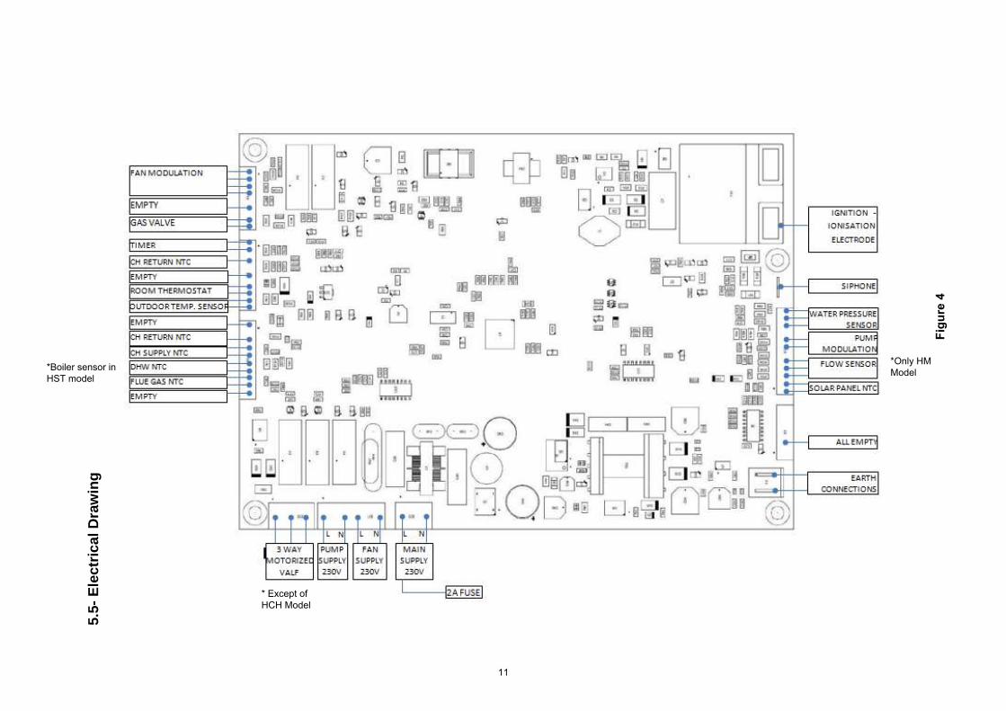
5.5-
Ele
ctric
al D
raw
ing
Figu
re 4
*Boiler sensor inHST model
* Except ofHCH Model
*Only HMModel
11
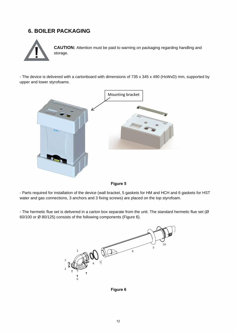
6. BOILER PACKAGING
CAUTION: Attention must be paid to warning on packaging regarding handling and storage.
- The device is delivered with a cartonboard with dimensions of 735 x 345 x 490 (HxWxD) mm, supported byupper and lower styrofoams.
Figure 5
- Parts required for installation of the device (wall bracket, 5 gaskets for HM and HCH and 6 gaskets for HSTwater and gas connections, 3 anchors and 3 fixing screws) are placed on the top styrofoam.
- The hermetic flue set is delivered in a carton box separate from the unit. The standard hermetic flue set (Ø60/100 or Ø 80/125) consists of the following components (Figure 6).
Figure 6
Mounting bracket
12
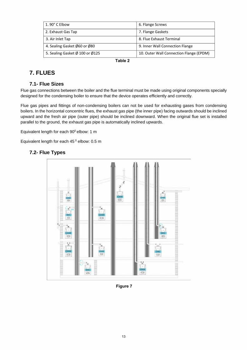
2. Exhaust Gas Tap 7. Flange Gaskets 3. Air Inlet Tap
8. Flue Exhaust Terminal
4. Sealing Gasket Ø60 or Ø80
9. Inner Wall Connection Flange 5. Sealing Gasket Ø 100 or Ø125 10. Outer Wall Connection Flange (EPDM)
Table 2
7. FLUES
7.1- Flue SizesFlue gas connections between the boiler and the flue terminal must be made using original components specially designed for the condensing boiler to ensure that the device operates efficiently and correctly.
Flue gas pipes and fittings of non-condensing boilers can not be used for exhausting gases from condensing boilers. In the horizontal concentric flues, the exhaust gas pipe (the inner pipe) facing outwards should be inclined upward and the fresh air pipe (outer pipe) should be inclined downward. When the original flue set is installed parallel to the ground, the exhaust gas pipe is automatically inclined upwards.
Equivalent length for each 900 elbow: 1 m
Equivalent length for each 45 0 elbow: 0.5 m
7.2- Flue Types
Figure 7
1. 90° C Elbow 6. Flange Screws
13
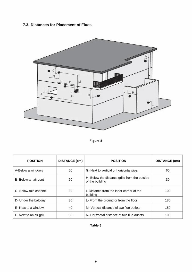
7.3- Distances for Placement of Flues
Figure 8
POSITION DISTANCE (cm) POSITION DISTANCE (cm)
A-Below a windows 60 G- Next to vertical or horizontal pipe 60
B- Below an air vent 60 H- Below the distance grille from the outsideof the building 30
C- Below rain channel 30 I- Distance from the inner corner of thebuilding
100
D- Under the balcony 30 L- From the ground or from the floor 180
E- Next to a window 40 M- Vertical distance of two flue outlets 150
F- Next to an air grill 60 N- Horizontal distance of two flue outlets 100
Table 3
14
8- INSTALLATION
8.1- Selection of Installation Location of DeviceThe boiler must be installed in accordance with gas safety regulations and relevant standards. Additionally, the clearance around the boiler should be as shown in fig 4. In order to make service, maintenance and usage easier.
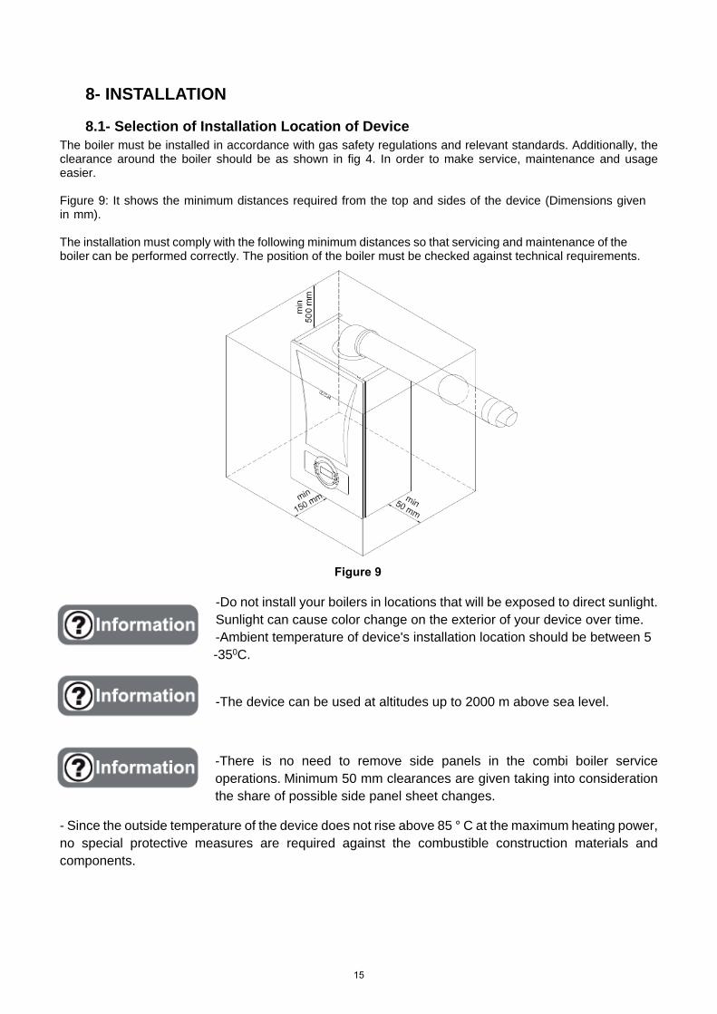
Figure 9: It shows the minimum distances required from the top and sides of the device (Dimensions given in mm).
The installation must comply with the following minimum distances so that servicing and maintenance of the boiler can be performed correctly. The position of the boiler must be checked against technical requirements.
Figure 9
-Do not install your boilers in locations that will be exposed to direct sunlight.Sunlight can cause color change on the exterior of your device over time.-Ambient temperature of device's installation location should be between 5-350C.
-The device can be used at altitudes up to 2000 m above sea level.
-There is no need to remove side panels in the combi boiler serviceoperations. Minimum 50 mm clearances are given taking into considerationthe share of possible side panel sheet changes.
- Since the outside temperature of the device does not rise above 85 ° C at the maximum heating power,no special protective measures are required against the combustible construction materials andcomponents.
15
8.2- Independent Operation from Ambient Air (Type C)
DANGER: For room sealed operation, the boiler location and air/flue terminal position must obey national and local requirements, gas safety regulations and relevant standards.
-Type C (hermetic) devices are not suitable for outdoor installations. These devices should be installed inside thebuilding.
-In case of gas leakage, it is necessary to vent the installation room according to national and local requirements,although the room sealed operation boilers are independent of room volume and ventilation.
DANGER: Do not block the air vents which provide fresh air to the installation room.
-The air/flue terminal must be exposed to the external air and allow free passage of air cross it at all times.-The minimum acceptable dimensions from the terminal to obstructions an ventilation openings must obey nationaland local requirements.- All horizontally fitted ducts (air/flue) should be fitted 2° or 3° upwards incline to allow condensate water drain tothe boiler.
-The flue ducts are always wet.
-Under cold or excessive humid weather conditions the water vapor inside the wastegas may condensate while leaving the flue.
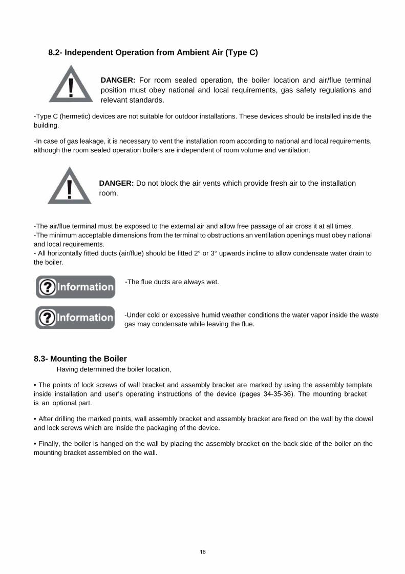
8.3- Mounting the Boiler Having determined the boiler location,
• The points of lock screws of wall bracket and assembly bracket are marked by using the assembly templateinside installation and user’s operating instructions of the device (pages 34-35-36). The mounting bracketis an optional part.
• After drilling the marked points, wall assembly bracket and assembly bracket are fixed on the wall by the doweland lock screws which are inside the packaging of the device.
• Finally, the boiler is hanged on the wall by placing the assembly bracket on the back side of the boiler on themounting bracket assembled on the wall.
16
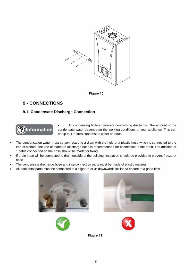
Figure 10
9 - CONNECTIONS
9.1- Condensate Discharge Connection
• All condensing boilers generate condensing discharge. The amount of thecondensate water depends on the working conditions of your appliance. This canbe up to 1.7 litres condensate water an hour.
• The condensation water must be connected to a drain with the help of a plastic hose which is connected to theend of siphon. The use of standard discharge hose is recommended for connection to the drain. The addition of1 cable connection on the hose should be made for fixing.
• If drain hose will be connected to drain outside of the building, insulation should be provided to prevent freeze ofhose.
• The condensate discharge hose and interconnection parts must be made of plastic material.• All horizontal parts must be connected at a slight 2° or 3° downwards incline to ensure to a good flow.
Figure 11
17
9.2- Gas and Water Connections
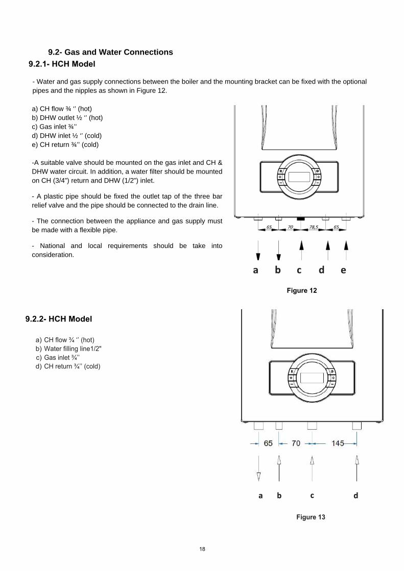
- Water and gas supply connections between the boiler and the mounting bracket can be fixed with the optionalpipes and the nipples as shown in Figure 12.
a) CH flow ¾ ‘’ (hot)b) DHW outlet ½ ‘’ (hot)c) Gas inlet ¾’’d) DHW inlet ½ ‘’ (cold)e) CH return ¾’’ (cold)
-A suitable valve should be mounted on the gas inlet and CH &DHW water circuit. In addition, a water filter should be mountedon CH (3/4”) return and DHW (1/2”) inlet.
- A plastic pipe should be fixed the outlet tap of the three barrelief valve and the pipe should be connected to the drain line.
- The connection between the appliance and gas supply mustbe made with a flexible pipe.
- National and local requirements should be take intoconsideration.
Figure 12
9.2.2- HCH Model
a b C d
a) CH flow ¾ ‘’ (hot)b) Water filling line1/2"c) Gas inlet ¾’’d) CH return ¾’’ (cold)
Figure 13
9.2.1- HCH Model
18
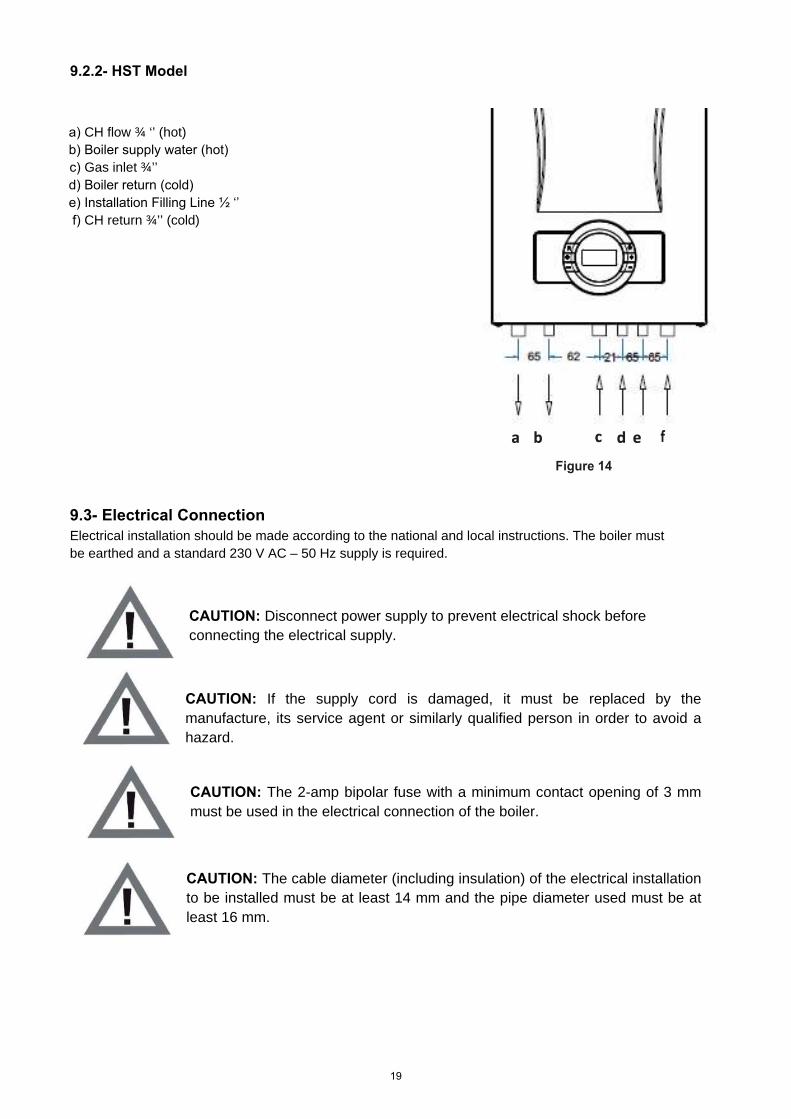
9.3- Electrical Connection Electrical installation should be made according to the national and local instructions. The boiler must be earthed and a standard 230 V AC – 50 Hz supply is required.
CAUTION: Disconnect power supply to prevent electrical shock before connecting the electrical supply.
CAUTION: If the supply cord is damaged, it must be replaced by the manufacture, its service agent or similarly qualified person in order to avoid a hazard.
CAUTION: The 2-amp bipolar fuse with a minimum contact opening of 3 mm must be used in the electrical connection of the boiler.
CAUTION: The cable diameter (including insulation) of the electrical installation to be installed must be at least 14 mm and the pipe diameter used must be at least 16 mm.
9.2.2- HST Model
a) CH flow ¾ ‘’ (hot)b) Boiler supply water (hot)c) Gas inlet ¾’’d) Boiler return (cold)e) Installation Filling Line ½ ‘’f) CH return ¾’’ (cold)
a b C d e f
Figure 14
19

9.4- Room Thermostat Optional room thermostats compatible with your device can be used to control heating system.
Figure 15
E.C.A. On/Off RoomThermostat
T6360 7006901312
E.C.A. Digital Room Modulated,ProgrammableLAGO FB OT 7006902518
E.C.A. Smart RoomThermostat
T6360 7006907531
E.C.A. Digital Room ThermostatNo Wire,Programmable
CM 7277006902046
E.C.A. Digital Room ThermostatDT90
70069020502
E.C.A. On/Off No Wire Room Thermostat7006907522
E.C.A. On/Off No Wire Room Thermostat7006907519
E.C.A. Programmable DigitalRoom Thermostat
CM707 7006901313
No Wire7006901501
20
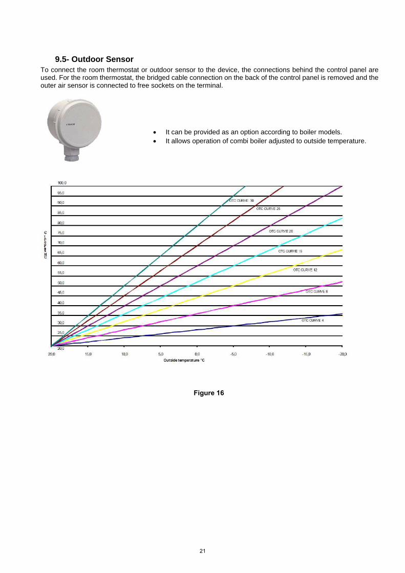
9.5- Outdoor Sensor To connect the room thermostat or outdoor sensor to the device, the connections behind the control panel are used. For the room thermostat, the bridged cable connection on the back of the control panel is removed and the outer air sensor is connected to free sockets on the terminal.
Figure 16
• It can be provided as an option according to boiler models.• It allows operation of combi boiler adjusted to outside temperature.
21
A
B
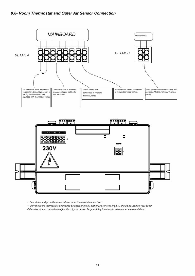
DETAIL A
MAINBOARD
To make the room thermostat connection, the bridge shown in the figure is removed and replaced with thermostat cables
Outdoor sensor is installed by connecting its cables to free terminals.
Timer cables are connected to relevant terminal points.
Boiler sensor cables connected to relevant terminal points.
DETA IL B
MAINBOARD
Solar system connection cables are connected to the indicated terminal points.
9.6- Room Thermostat and Outer Air Sensor Connection
• Cancel the bridge on the other side on room thermostat connection.• Only the room thermostats deemed to be appropriate by authorized services of E.C.A. should be used on your boiler. Otherwise, it may cause the malfunction of your device. Responsibility is not undertaken under such conditions.
22
The connections of room thermostat, outdoor sensor and timer must be performed certainly by qualified person.
10- COMMISSIONING, USE AND TURNING OFF THE BOILER
10.1- Commissioning, Filling Water into Boiler and Heater Installation
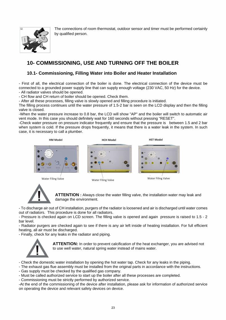
- First of all, the electrical connection of the boiler is done. The electrical connection of the device must beconnected to a grounded power supply line that can supply enough voltage (230 VAC, 50 Hz) for the device.- All radiator valves should be opened.- CH flow and CH return of boiler should be opened. Check them.- After all these processes, filling valve is slowly opened and filling procedure is initiated.The filling process continues until the water pressure of 1.5-2 bar is seen on the LCD display and then the fillingvalve is closed.-When the water pressure increase to 0.8 bar, the LCD will show "AP" and the boiler will switch to automatic airvent mode. In this case you should definitely wait for 160 seconds without pressing "RESET".-Check water pressure on pressure indicator frequently and ensure that the pressure is between 1.5 and 2 barwhen system is cold. If the pressure drops frequently, it means that there is a water leak in the system. In suchcase, it is necessary to call a plumber.
ATTENTION : Always close the water filling valve, the installation water may leak and damage the environment.
- To discharge air out of CH installation, purgers of the radiator is loosened and air is discharged until water comesout of radiators. This procedure is done for all radiators.- Pressure is checked again on LCD screen. The filling valve is opened and again pressure is raised to 1.5 - 2bar level.- Radiator purgers are checked again to see if there is any air left inside of heating installation. For full efficientheating, all air must be discharged.- Finally, check for any leaks in the radiator and piping.
ATTENTION: In order to prevent calcification of the heat exchanger, you are advised not to use well water, natural spring water instead of mains water.
- Check the domestic water installation by opening the hot water tap. Check for any leaks in the piping.- The exhaust gas flue assembly must be installed from the original parts in accordance with the instructions.- Gas supply must be checked by the qualified gas company.- Must be called authorized service to start up the boiler after all these processes are completed.- Commissioning must be strictly performed by authorized service.-At the end of the commissioning of the device after installation, please ask for information of authorized serviceon operating the device and relevant safety devices on device.
Water Filing Valve
HM Model
Water Filing Valve Water Filing Valve
HCH Model HST Model
23
10.2- Using the Device
10.2.1- Switching off the Device You can switch off the boiler by holding down the ON/ OFF button for 3 seconds.
LCD light will be OFF after 1 minute.
Anti-freeze function remains active.
11-CONTROL PANEL
11.1- Functions of Buttons
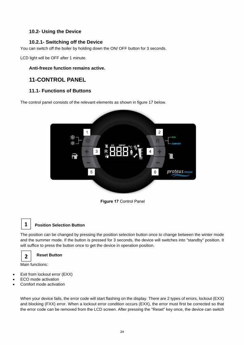
The control panel consists of the relevant elements as shown in figure 17 below.
Figure 17 Control Panel
Position Selection Button
The position can be changed by pressing the position selection button once to change between the winter mode and the summer mode. If the button is pressed for 3 seconds, the device will switches into "standby" position. It will suffice to press the button once to get the device in operation position.
Reset Button
Main functions:
• Exit from lockout error (EXX)• ECO mode activation• Comfort mode activation
When your device fails, the error code will start flashing on the display. There are 2 types of errors, lockout (EXX) and blocking (FXX) error. When a lockout error condition occurs (EXX), the error must first be corrected so that the error code can be removed from the LCD screen. After pressing the "Reset" key once, the device can switch
1
2
24
back to normal operation state. As for a blocking error, the fault cannot be removed from the LCD display pressing the "Reset" button (FXX). When this error is corrected, error code is automatically disappears from LCD screen. The first time the device starts, it will start working in Comfort mode.
Once the Reset button is pressed when operating in Comfort mode, the device will switch to Eco mode. Then when Reset button is pressed again, the unit will switch to Comfort mode.
Domestic Hot Water Increase Temperature Button
The temperature of the domestic water can be increased up to 65 °C thanks to the domestic water temperature increase button.
Central Heating Water Increase Temperature Button
The temperature of the heating water can be increased up to 80 °C thanks to the heating water temperature increase button.
Domestic Hot Water Decrease Temperature Button
The temperature of the domestic water can be decreased down to 30 °C thanks to the domestic water temperature decrease button.
Central Heating Water Decrease Temperature Button
The temperature of the heating water can be decreased down to 30 °C thanks to the heating water temperature decrease button.
11.2- LCD Screen
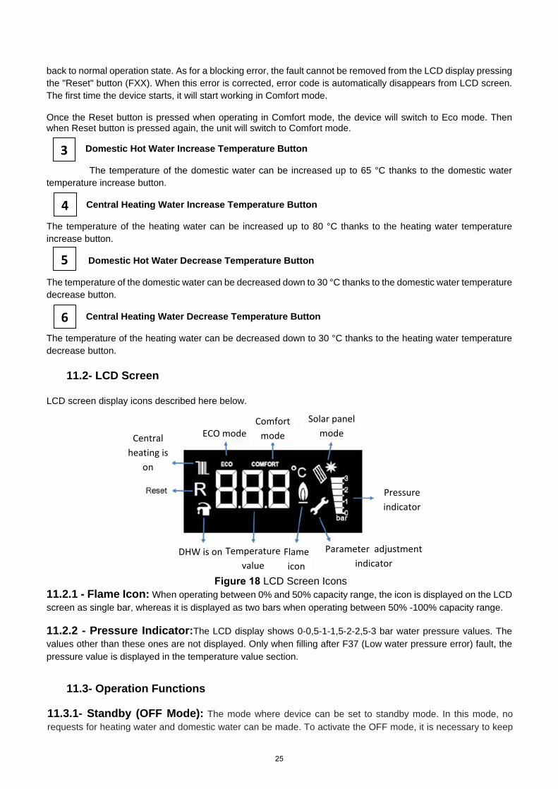
LCD screen display icons described here below.
Figure 18 LCD Screen Icons 11.2.1 - Flame Icon: When operating between 0% and 50% capacity range, the icon is displayed on the LCDscreen as single bar, whereas it is displayed as two bars when operating between 50% -100% capacity range.
11.2.2 - Pressure Indicator:The LCD display shows 0-0,5-1-1,5-2-2,5-3 bar water pressure values. Thevalues other than these ones are not displayed. Only when filling after F37 (Low water pressure error) fault, the pressure value is displayed in the temperature value section.
11.3- Operation Functions
11.3.1- Standby (OFF Mode): The mode where device can be set to standby mode. In this mode, norequests for heating water and domestic water can be made. To activate the OFF mode, it is necessary to keep
3
4
5
6
ECO mode Comfort
mode
Solar panel mode
Pressure indicator
Central heating is
on
DHW is on Parameter adjustment indicator
Flame icon
Temperature value
25
button no. 1 (position selector) pressed for 3 seconds continuously. When -OFF- is displayed on screen, mode is activated.
11.3.2- Air Discharge Mode (AP Mode): It is the process that the device automatically activates todischarge air in the central heating installation for 160 seconds. In this mode, "AP" is displayed on the screen. The circulation pump runs for 15 seconds an then stops every 5 seconds in intervals of every 20 seconds. The three-way valve motor also changes position between a CH-DHW in 40 seconds. The situations where this mode is activated is listed here below.
• Once the device is powered for the first time or after the electricity has been switched off and on,• After the reset operation following the overheating fault (E03),• After elimination of high water pressure (F40) or low water pressure (F37) error,
Do not press 'RESET' while AP mode is active.
11.3.3- Winter mode-Radiator Heating: If the device in the standby position is set to the winter position,the appliance will heat the water in the heating circuit until the domestic water is needed. In the winter mode, both the tap and the radiator icon are displayed on the LCD screen.
When a request for heating is made for radiator, radiator icon flashes (once/second), tap icon stays fixed. When a request for domestic water is made, tap icon flashes (once/second), radiator icon stays fixed. In this mode, radiator heating circuit's temperature can be set between 30-80 ͦC. For under floor heating applications, the temperature range can be set between 30-45 ͦC.
11.3.4- Summer Mode: If the device in the OFF position is set to the summer position, the device will onlyrespond to the domestic hot water demands. In summer mode, the tap symbol appears fixed on the LCD screen, the radiator icon does not appear. When the domestic hot water is heating request, the tap symbol flashes (1 time / second). In this mode, the domestic hot water temperature can be adjusted between 30-65 °C.
11.3.5- Comfort Mode: The standard operating mode of the device is Comfort mode. By pressing the"Reset" button, Eco-Comfort modes can be switched. When Comfort mode is active, "Comfort" icon is displayed on the LCD screen. Comfort mode is only for radiator heating circuit. It has no effect on use of domestic water circuit. In this mode, the device responds to fast heating demands by running in modulation.
11.3.6- ECO Mode: By pressing the "Reset" button, Eco-Comfort modes can be switched. When Eco modeis active, "Eco" icon is displayed on the LCD screen. Eco mode is only for radiator heating circuit. It has no effect on use of domestic water circuit. This mode allows savings on fuel by performing on-off operation.
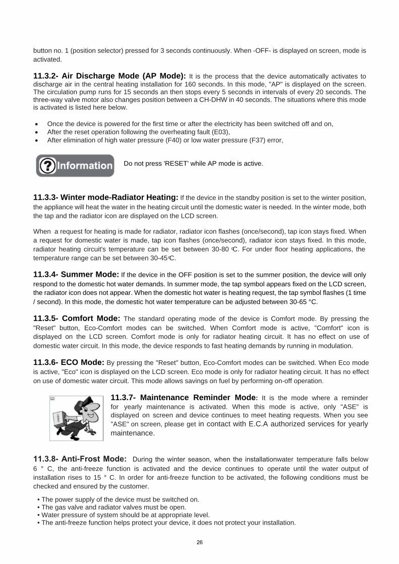
11.3.7- Maintenance Reminder Mode: It is the mode where a reminderfor yearly maintenance is activated. When this mode is active, only "ASE" is displayed on screen and device continues to meet heating requests. When you see "ASE" on screen, please get in contact with E.C.A authorized services for yearly maintenance.
11.3.8- Anti-Frost Mode: During the winter season, when the installationwater temperature falls below6 ° C, the anti-freeze function is activated and the device continues to operate until the water output of installation rises to 15 ° C. In order for anti-freeze function to be activated, the following conditions must be checked and ensured by the customer.
• The power supply of the device must be switched on.• The gas valve and radiator valves must be open.• Water pressure of system should be at appropriate level.• The anti-freeze function helps protect your device, it does not protect your installation.
26
• If device will not be operated for a while in places where there is risk of freezing, then it is necessary to drainthe water or to use an anti-freeze agent.
12 – GAS CONVERSION
Gas conversion operation from LPG to natural gas or from natural gas to LPG should be performed by authorized service. If the user requests gas transformation after purchase of the device, it is subject to a fee.
For the gas conversion process, a conversion kit is required. The conversion kit includes 1 gas orifice, 1 klingerite gasket and 1 gas conversion label. Procedure for gas conversion;
• Installation of parts in the conversion kit• Gas adjustment• Parameter change (P01: 0 for natural gas, P01:1 for LPG)
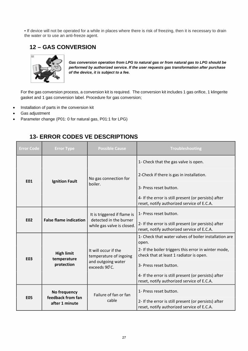
13- ERROR CODES VE DESCRIPTIONS
Error Code Error Type Possible Cause Troubleshooting
E01 Ignition Fault No gas connection for boiler.
1- Check that the gas valve is open.
2-Check if there is gas in installation.
3- Press reset button.
4- If the error is still present (or persists) afterreset, notify authorized service of E.C.A.
E02 False flame indication It is triggered if flame is detected in the burner
while gas valve is closed.
1- Press reset button.
2- If the error is still present (or persists) afterreset, notify authorized service of E.C.A.
E03 High limit
temperature protection
It will occur if the temperature of ingoing and outgoing water exceeds 90 ͦC.
1- Check that water valves of boiler installation areopen.
2- If the boiler triggers this error in winter mode,check that at least 1 radiator is open.
3- Press reset button.
4- If the error is still present (or persists) afterreset, notify authorized service of E.C.A.
E05 No frequency
feedback from fan after 1 minute
Failure of fan or fan cable
1- Press reset button.
2- If the error is still present (or persists) afterreset, notify authorized service of E.C.A.
27
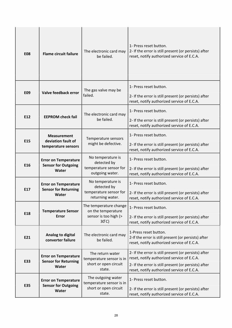
E08 Flame circuit failure The electronic card may be failed.
1- Press reset button.2- If the error is still present (or persists) afterreset, notify authorized service of E.C.A.
E09 Valve feedback error The gas valve may be failed.
1- Press reset button.
2- If the error is still present (or persists) afterreset, notify authorized service of E.C.A.
E12 EEPROM check fail The electronic card may be failed.
1- Press reset button.
2- If the error is still present (or persists) afterreset, notify authorized service of E.C.A.
E15 Measurement
deviation fault of temperature sensors
Temperature sensors might be defective.
1- Press reset button.
2- If the error is still present (or persists) afterreset, notify authorized service of E.C.A.
E16 Error on Temperature Sensor for Outgoing
Water
No temperature is detected by
temperature sensor for outgoing water.
1- Press reset button.
2- If the error is still present (or persists) afterreset, notify authorized service of E.C.A.
E17 Error on Temperature Sensor for Returning
Water
No temperature is detected by
temperature sensor for returning water.
1- Press reset button.
2- If the error is still present (or persists) afterreset, notify authorized service of E.C.A.
E18 Temperature Sensor Error
The temperature change on the temperature sensor is too high (>
30 ͦC)
1- Press reset button.
2- If the error is still present (or persists) afterreset, notify authorized service of E.C.A.
E21 Analog to digital converter failure
The electronic card may be failed.
1-Press reset button.2-If the error is still present (or persists) afterreset, notify authorized service of E.C.A.
E33 Error on Temperature Sensor for Returning
Water
The return water temperature sensor is in
short or open circuit state.
2- If the error is still present (or persists) afterreset, notify authorized service of E.C.A.
2- If the error is still present (or persists) afterreset, notify authorized service of E.C.A.
E35 Error on Temperature Sensor for Outgoing
Water
The outgoing water temperature sensor is in
short or open circuit state.
1- Press reset button.
2- If the error is still present (or persists) afterreset, notify authorized service of E.C.A.
28
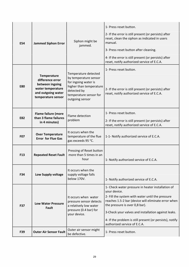
E54 Jammed Siphon Error Siphon might be jammed.
1- Press reset button.
2- If the error is still present (or persists) afterreset, clean the siphon as indicated in usersmanual.
3- Press reset button after cleaning.
4- If the error is still present (or persists) afterreset, notify authorized service of E.C.A.
E80
Temperature difference error between ingoing
water temperature and outgoing water temperature sensor
Temperature detected by temperature sensor for ingoing water is higher than temperature detected by temperature sensor for outgoing sensor
1- Press reset button.
2- If the error is still present (or persists) afterreset, notify authorized service of E.C.A.
E82 Flame failure (more than 3 flame failures
in 4 minutes)
Flame detection problem
1- Press reset button.
2- If the error is still present (or persists) afterreset, notify authorized service of E.C.A.
F07 Over Temperature Error for Flue Gas
It occurs when the temperature of the flue gas exceeds 95 oC.
1-1- Notify authorized service of E.C.A.
F13 Repeated Reset Fault Pressing of Reset button more than 5 times in an
hour 1- Notify authorized service of E.C.A.
F34 Low Supply voltage It occurs when the supply voltage falls below 170V. 1- Notify authorized service of E.C.A.
F37 Low Water Pressure Fault
It occurs when water pressure sensor detects a relatively low water pressure (0.4 bar) for your device.
1- Check water pressure in heater installation ofyour device.2- Fill the system with water until the pressurereaches 1.5-2 bar (device will eliminate error whenthe pressure is over 0,8 bar).
3-Check your valves and installation against leaks.
4- If the problem is still present (or persists), notifyauthorized service of E.C.A.
F39 Outer Air Sensor Fault Outer air sensor might be defective. 1- Press reset button.
29
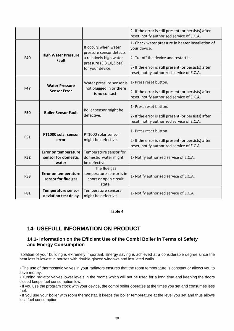
2- If the error is still present (or persists) afterreset, notify authorized service of E.C.A.
F40 High Water Pressure Fault
It occurs when water pressure sensor detects a relatively high water pressure (3,3 ±0,3 bar) for your device.
1- Check water pressure in heater installation ofyour device.
2- Tur off the device and restart it.
3- If the error is still present (or persists) afterreset, notify authorized service of E.C.A.
F47 Water Pressure Sensor Error
Water pressure sensor is not plugged in or there
is no contact.
1- Press reset button.
2- If the error is still present (or persists) afterreset, notify authorized service of E.C.A.
F50 Boiler Sensor Fault Boiler sensor might be defective.
1- Press reset button.
2- If the error is still present (or persists) afterreset, notify authorized service of E.C.A.
F51 PT1000 solar sensor error
PT1000 solar sensor might be defective.
1- Press reset button.
2- If the error is still present (or persists) afterreset, notify authorized service of E.C.A.
F52 Error on temperature sensor for domestic
water
Temperature sensor for domestic water might be defective.
1- Notify authorized service of E.C.A.
F53 Error on temperature sensor for flue gas
The flue gas temperature sensor is in
short or open circuit state.
1- Notify authorized service of E.C.A.
F81 Temperature sensor deviation test delay
Temperature sensors might be defective. 1- Notify authorized service of E.C.A.
Table 4
14- USEFULL INFORMATION ON PRODUCT
14.1- Information on the Efficient Use of the Combi Boiler in Terms of Safety and Energy Consumption
Isolation of your building is extremely important. Energy saving is achieved at a considerable degree since the heat loss is lowest in houses with double-glazed windows and insulated walls.
• The use of thermostatic valves in your radiators ensures that the room temperature is constant or allows you tosave money.• Turning radiator valves lower levels in the rooms which will not be used for a long time and keeping the doorsclosed keeps fuel consumption low.• If you use the program clock with your device, the combi boiler operates at the times you set and consumes lessfuel.• If you use your boiler with room thermostat, it keeps the boiler temperature at the level you set and thus allowsless fuel consumption.
30
• Covering the radiator top and sides with furniture-like things negatively affects hot air circulation, thus preventsthe environment from overheating and increases fuel consumption.• If you will leave your device in operation late at night, keeping water temperature of the heating circuit at lowlevels will ensure saving.• If you feel that the room temperature is high, the radiator valves should be closed instead of opening windows.
14.2- Clogging in Installation • In old installations with iron pipes, usually clogging occurs short time after the device is commissioned.• If clogging in installation is encountered with, then inhibitor (Sentinel X400, etc.) should be added to installationwater.
14.3- Cleaning of Boiler Keep the outer casing of the combi boiler clean by wiping it with a soft damped cloth. Do not use strong, abrasive cleaning agents.
Performing the maintenance once a year during the warranty period and periodically before the winter season after the warranty expires ensures safe use, saves fuel and extends the useful life of the boiler.
Make sure periodic maintenance is strictly performed by E.C.A. Authorized Services.
Use original spares parts only to ensure maximum life span and safety of the device.
E.C.A will not be responsible for damages to device or material or living beings nearby caused by maintenanceperformed by unauthorized service or staff.
31
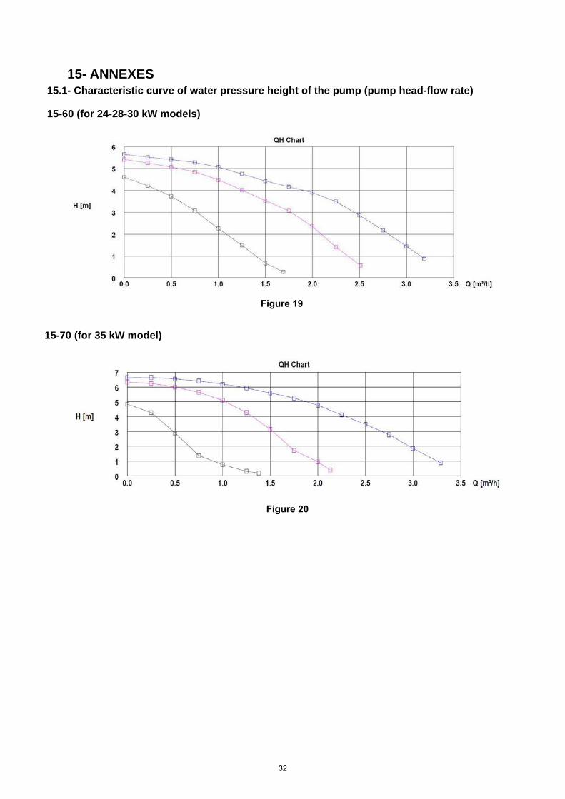
15- ANNEXES15.1- Characteristic curve of water pressure height of the pump (pump head-flow rate)
15-60 (for 24-28-30 kW models)
Figure 19
15-70 (for 35 kW model)
Figure 20
32
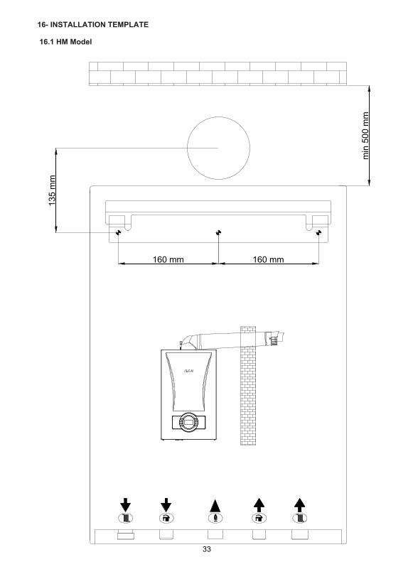
16- INSTALLATION TEMPLATE
16.1 HM Model
33
E E
L!') C") .....
160 mm
• +00 ®
160 mm
+ cJiD
E E o o L!')
C
.E
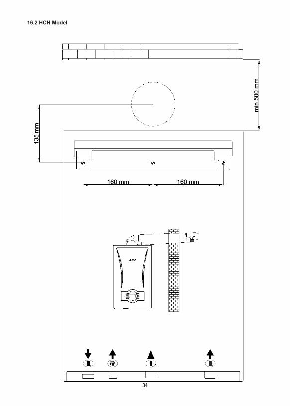
16.2 HCH Model
34
E E
L!') C") .....
160 mm
• • 00 C[)
160 mm
E E o o L!')
C
.E
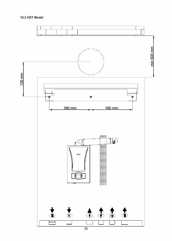
16.2 HST Model
35
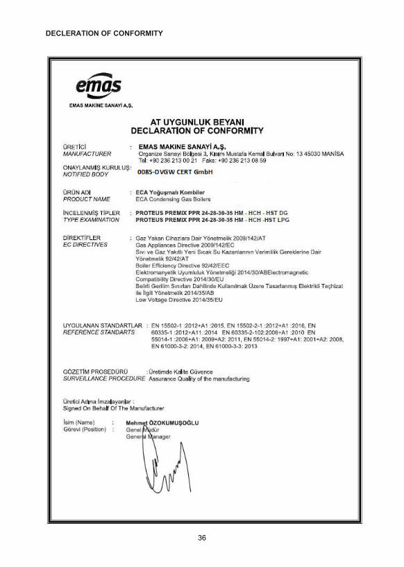
DECLERATION OF CONFORMITY
36
37
yalcinoter
IPTAL
38


7006990185-0.6
Related Documents