Journal of Mechatronics, Electrical Power, and Vehicular Technology 12 (2021) 28-37 Journal of Mechatronics, Electrical Power, and Vehicular Technology e-ISSN: 2088-6985 p-ISSN: 2087-3379 mev.lipi.go.id doi: https://dx.doi.org/10.14203/j.mev.2021.v12.28-37 2088-6985 / 2087-3379 ©2019 Research Centre for Electrical Power and Mechatronics - Indonesian Institute of Sciences (RCEPM LIPI). This is an open access article under the CC BY-NC-SA license (https://creativecommons.org/licenses/by-nc-sa/4.0/). MEV is Sinta 1 Journal (https://sinta.ristekbrin.go.id/journals/detail?id=814) accredited by Ministry of Research & Technology, Republic Indonesia Proteus ISIS simulation for power factor calculation using zero crossing detector Jumrianto a, *, Royan b a System and Information Technology Department, IVET University Jl. Pawiyatan Luhur, Semarang, 50235, Indonesia b Electromedical Engineering Department, Muhammadiyah University Purwokerto, Jl. KH. Ahmad Dahlan Purwokerto, Banyumas, 53182, Indonesia Received 21 February 2021; Accepted 3 June 2021; Published online 31 July 2021 Abstract One of the important parameters for electrical systems is the power factor (cos phi), which is the ratio of the real power (watt) to the apparent power (volt ampere). The best cos phi value is between 0.85 to 1. A resistive load causes the voltage and current in equal phase angle, while the inductive load causes the current to lag behind the voltage. On the other hand, the capacitive load causes the current to precede the voltage (leading). A simulation to determine the power factor of an electrical network can be done with Proteus ISIS software by creating a phase detection circuit. Automatic control can be done by a microcontroller. This simulation circuit can be used as power factor correction, a trigger angle on SCR trigger for DC motor speed control, for rocket launch angle adjuster, to measure the angle of inclination, and other uses relating to angle adjustments. ©2021 Research Centre for Electrical Power and Mechatronics - Indonesian Institute of Sciences. This is an open access article under the CC BY-NC-SA license (https://creativecommons.org/licenses/by-nc-sa/4.0/). Keywords: power factor; cos phi; zero-crossing. I. Introduction Power quality determines the reliability of the electrical system. One of the important parameters to be considered for electrical system reliability is a power factor (cos phi). Power factor is determined by how far the phase degree difference (cos) between voltage and current. Understanding the power factor and how it affects the utility bill can help reduce electricity costs. The effect of load on generator performance, particularly output power, efficiency, and voltage regulation, can be seen by designing two types of simulated loads: pure resistive and series resistive-inductive loads. Each type of load provides a power factor of 1 and 0.85, respectively. The simulation results show that the generator gives better performance when loaded with resistive loads [1]. The SEPIC converter works in intermittent conduction mode and functions as a power factor corrector so that the input current waveform follows the input voltage waveform. The full-bridge DC-DC converter functions as an output voltage regulator and operates in a continuous conduction mode, where the power factor of this converter system can achieve up to 0.96 [2]. If the current and voltage are both sinusoidal in one phase, the power factor is 1.0. If both are sinusoidal but in phase difference, the power factor is the cosine of the phase angle [3]. Zero-crossing Detector functions as a triggering start for the PWM signal so that the fan speed and light brightness can be adjusted [4]. Zero-crossing detectors are used to synchronize switching with the AC wavelength or to extract the timing signal. By using zero-crossing techniques, high inrush currents can be avoided [5]. The Zero- crossing Detector circuit functions well as a voltage safety net for the Indonesian State Electricity Company [6]. Different approaches are used for zero- crossing: hardware or software. The hardware approach is simple, but it has low precision. On the other hand, the software approach has high precision, but it is complicated and expensive [7]. Zero-voltage cross detection is commonly used as an accurate method of detecting AC characteristics, such as frequency and phase. The zero-crossing point is ideally suited for measuring AC signals for several reasons. A comparator is similar to an operational amplifier (Op-Amp). It has two inputs, * Corresponding Author. Phone: +62-813-4592-0696 E-mail address: [email protected]

Welcome message from author
This document is posted to help you gain knowledge. Please leave a comment to let me know what you think about it! Share it to your friends and learn new things together.
Transcript

Journal of Mechatronics, Electrical Power, and Vehicular Technology 12 (2021) 28-37
Journal of Mechatronics, Electrical Power, and Vehicular Technology
e-ISSN: 2088-6985 p-ISSN: 2087-3379
mev.lipi.go.id
doi: https://dx.doi.org/10.14203/j.mev.2021.v12.28-37 2088-6985 / 2087-3379 ©2019 Research Centre for Electrical Power and Mechatronics - Indonesian Institute of Sciences (RCEPM LIPI). This is an open access article under the CC BY-NC-SA license (https://creativecommons.org/licenses/by-nc-sa/4.0/). MEV is Sinta 1 Journal (https://sinta.ristekbrin.go.id/journals/detail?id=814) accredited by Ministry of Research & Technology, Republic Indonesia
Proteus ISIS simulation for power factor calculation using zero crossing detector
Jumrianto a, *, Royan b a System and Information Technology Department, IVET University
Jl. Pawiyatan Luhur, Semarang, 50235, Indonesia b Electromedical Engineering Department, Muhammadiyah University Purwokerto,
Jl. KH. Ahmad Dahlan Purwokerto, Banyumas, 53182, Indonesia
Received 21 February 2021; Accepted 3 June 2021; Published online 31 July 2021
Abstract
One of the important parameters for electrical systems is the power factor (cos phi), which is the ratio of the real power (watt) to the apparent power (volt ampere). The best cos phi value is between 0.85 to 1. A resistive load causes the voltage and current in equal phase angle, while the inductive load causes the current to lag behind the voltage. On the other hand, the capacitive load causes the current to precede the voltage (leading). A simulation to determine the power factor of an electrical network can be done with Proteus ISIS software by creating a phase detection circuit. Automatic control can be done by a microcontroller. This simulation circuit can be used as power factor correction, a trigger angle on SCR trigger for DC motor speed control, for rocket launch angle adjuster, to measure the angle of inclination, and other uses relating to angle adjustments.
©2021 Research Centre for Electrical Power and Mechatronics - Indonesian Institute of Sciences. This is an open access article under the CC BY-NC-SA license (https://creativecommons.org/licenses/by-nc-sa/4.0/).
Keywords: power factor; cos phi; zero-crossing.
I. Introduction
Power quality determines the reliability of the electrical system. One of the important parameters to be considered for electrical system reliability is a power factor (cos phi). Power factor is determined by how far the phase degree difference (cos) between voltage and current. Understanding the power factor and how it affects the utility bill can help reduce electricity costs. The effect of load on generator performance, particularly output power, efficiency, and voltage regulation, can be seen by designing two types of simulated loads: pure resistive and series resistive-inductive loads. Each type of load provides a power factor of 1 and 0.85, respectively. The simulation results show that the generator gives better performance when loaded with resistive loads [1]. The SEPIC converter works in intermittent conduction mode and functions as a power factor corrector so that the input current waveform follows the input voltage waveform. The full-bridge DC-DC converter functions as an output
voltage regulator and operates in a continuous conduction mode, where the power factor of this converter system can achieve up to 0.96 [2]. If the current and voltage are both sinusoidal in one phase, the power factor is 1.0. If both are sinusoidal but in phase difference, the power factor is the cosine of the phase angle [3]. Zero-crossing Detector functions as a triggering start for the PWM signal so that the fan speed and light brightness can be adjusted [4]. Zero-crossing detectors are used to synchronize switching with the AC wavelength or to extract the timing signal. By using zero-crossing techniques, high inrush currents can be avoided [5]. The Zero-crossing Detector circuit functions well as a voltage safety net for the Indonesian State Electricity Company [6]. Different approaches are used for zero-crossing: hardware or software. The hardware approach is simple, but it has low precision. On the other hand, the software approach has high precision, but it is complicated and expensive [7]. Zero-voltage cross detection is commonly used as an accurate method of detecting AC characteristics, such as frequency and phase. The zero-crossing point is ideally suited for measuring AC signals for several reasons. A comparator is similar to an operational amplifier (Op-Amp). It has two inputs,
* Corresponding Author. Phone: +62-813-4592-0696
E-mail address: [email protected]
Jumrianto and Royan / Journal of Mechatronics, Electrical Power, and Vehicular Technology 12 (2021) 28-37
29
inverting and non-inverting, and an output, but it is specifically designed to compare the voltages between its two inputs. A suitable zero-crossing circuit is often needed for devices such as lighting controllers, thermostats, motor drives, and similar AC-load controlling or monitoring applications, often needs mains phase and/or frequency information [8].
II. Materials and Methods
The phase difference is obtained by comparing the phase voltage and phase currents drawn by the load. The voltage and current waves of a sensor are still sine signals where the two phases are different [9]. A comparator is used to distinguish between two different signal levels [10].
Comparator is similar to Op-Amp. A comparator has two inputs (inverting/non-inverting) and output. A comparator is a digital circuit in which all the output values are expressed as "yes = 1" or "no = 0". To facilitate the processing of a sine wave, a comparator is used to convert a sine wave into a square wave. Among the ICs that can be used is IC LM324, which has a 5 volt DC power supply source.
A. Comparator
The phase difference detector is made using Comparator and Exclusive-OR logic gates. The comparator is used to convert a sine wave into a square wave, while the Exclusive-OR logic gate is used to pass a square wave (value 1) only when the two inputs are different. If the input waveform is equal, either equals 0 or equals 1, then the output will be 0.
The length of time the output is 0 or 1 depends on the magnitude of the phase angle. The cos difference value is obtained by calculating the time interval between the rising voltage and the down voltage at the Exclusive-OR logic gate output [11]. Design of a comparator block using one of the facilities provided by operational amplifier (Op-Amp) type LM-324 [9]. The schematic image of IC LM-324 [12] used as a comparator is shown in Figure 1.
B. Exclusive-OR logic gates (Ex-Or)
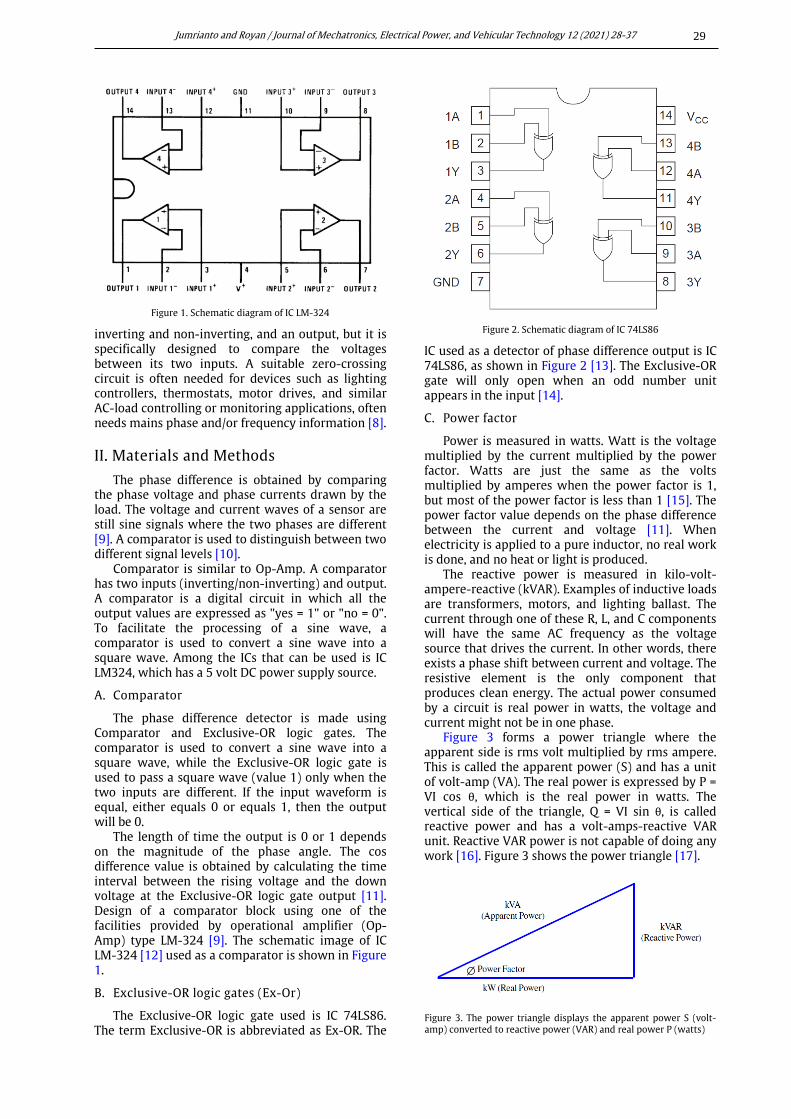
The Exclusive-OR logic gate used is IC 74LS86. The term Exclusive-OR is abbreviated as Ex-OR. The
IC used as a detector of phase difference output is IC 74LS86, as shown in Figure 2 [13]. The Exclusive-OR gate will only open when an odd number unit appears in the input [14].
C. Power factor
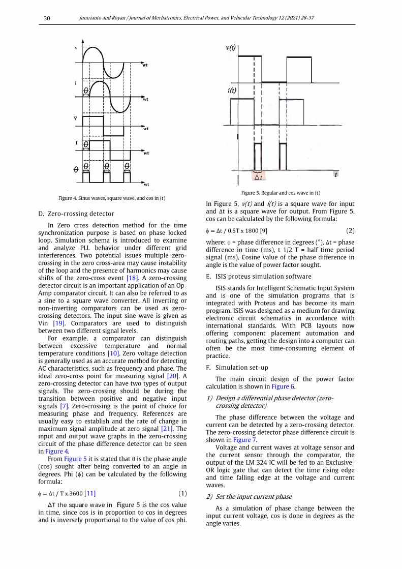
Power is measured in watts. Watt is the voltage multiplied by the current multiplied by the power factor. Watts are just the same as the volts multiplied by amperes when the power factor is 1, but most of the power factor is less than 1 [15]. The power factor value depends on the phase difference between the current and voltage [11]. When electricity is applied to a pure inductor, no real work is done, and no heat or light is produced.
The reactive power is measured in kilo-volt-ampere-reactive (kVAR). Examples of inductive loads are transformers, motors, and lighting ballast. The current through one of these R, L, and C components will have the same AC frequency as the voltage source that drives the current. In other words, there exists a phase shift between current and voltage. The resistive element is the only component that produces clean energy. The actual power consumed by a circuit is real power in watts, the voltage and current might not be in one phase.
Figure 3 forms a power triangle where the apparent side is rms volt multiplied by rms ampere. This is called the apparent power (S) and has a unit of volt-amp (VA). The real power is expressed by P = VI cos θ, which is the real power in watts. The vertical side of the triangle, Q = VI sin θ, is called reactive power and has a volt-amps-reactive VAR unit. Reactive VAR power is not capable of doing any work [16]. Figure 3 shows the power triangle [17].
Figure 1. Schematic diagram of IC LM-324
Figure 2. Schematic diagram of IC 74LS86
Figure 3. The power triangle displays the apparent power S (volt-amp) converted to reactive power (VAR) and real power P (watts)
Jumrianto and Royan / Journal of Mechatronics, Electrical Power, and Vehicular Technology 12 (2021) 28-37
30
D. Zero-rrossing detector
In Zero cross detection method for the time synchronization purpose is based on phase locked loop. Simulation schema is introduced to examine and analyze PLL behavior under different grid interferences. Two potential issues multiple zero-crossing in the zero cross-area may cause instability of the loop and the presence of harmonics may cause shifts of the zero-cross event [18]. A zero-crossing detector circuit is an important application of an Op-Amp comparator circuit. It can also be referred to as a sine to a square wave converter. All inverting or non-inverting comparators can be used as zero-crossing detectors. The input sine wave is given as Vin [19]. Comparators are used to distinguish between two different signal levels.
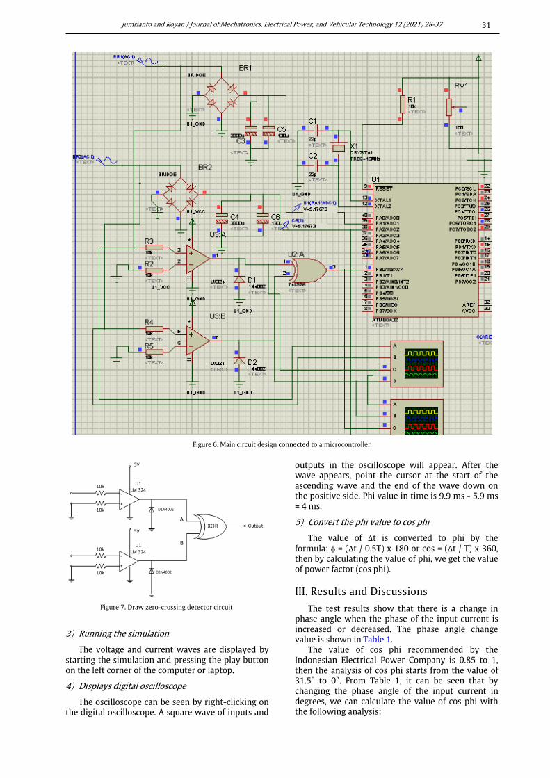
For example, a comparator can distinguish between excessive temperature and normal temperature conditions [10]. Zero voltage detection is generally used as an accurate method for detecting AC characteristics, such as frequency and phase. The ideal zero-cross point for measuring signal [20]. A zero-crossing detector can have two types of output signals. The zero-crossing should be during the transition between positive and negative input signals [7]. Zero-crossing is the point of choice for measuring phase and frequency. References are usually easy to establish and the rate of change in maximum signal amplitude at zero signal [21]. The input and output wave graphs in the zero-crossing circuit of the phase difference detector can be seen in Figure 4.
From Figure 5 it is stated that θ is the phase angle (cos) sought after being converted to an angle in degrees. Phi (φ) can be calculated by the following formula:
φ = Δt / T x 3600 [11] (1)
ΔT the square wave in Figure 5 is the cos value in time, since cos is in proportion to cos in degrees and is inversely proportional to the value of cos phi.
In Figure 5, v(t) and i(t) is a square wave for input and Δt is a square wave for output. From Figure 5, cos can be calculated by the following formula:
φ = Δt / 0.5T x 1800 [9] (2)
where: φ = phase difference in degrees (°), Δt = phase difference in time (ms), t 1/2 T = half time period signal (ms). Cosine value of the phase difference in angle is the value of power factor sought.
E. ISIS proteus simulation software
ISIS stands for Intelligent Schematic Input System and is one of the simulation programs that is integrated with Proteus and has become its main program. ISIS was designed as a medium for drawing electronic circuit schematics in accordance with international standards. With PCB layouts now offering component placement automation and routing paths, getting the design into a computer can often be the most time-consuming element of practice.
F. Simulation set-up
The main circuit design of the power factor calculation is shown in Figure 6.
1) Design a differential phase detector (zero-crossing detector)
The phase difference between the voltage and current can be detected by a zero-crossing detector. The zero-crossing detector phase difference circuit is shown in Figure 7.
Voltage and current waves at voltage sensor and the current sensor through the comparator, the output of the LM 324 IC will be fed to an Exclusive-OR logic gate that can detect the time rising edge and time falling edge at the voltage and current waves.
2) Set the input current phase
As a simulation of phase change between the input current voltage, cos is done in degrees as the angle varies.
Figure 4. Sinus waves, square wave, and cos in (t)
Figure 5. Regular and cos wave in (t)
Jumrianto and Royan / Journal of Mechatronics, Electrical Power, and Vehicular Technology 12 (2021) 28-37
31
3) Running the simulation
The voltage and current waves are displayed by starting the simulation and pressing the play button on the left corner of the computer or laptop.
4) Displays digital oscilloscope
The oscilloscope can be seen by right-clicking on the digital oscilloscope. A square wave of inputs and
outputs in the oscilloscope will appear. After the wave appears, point the cursor at the start of the ascending wave and the end of the wave down on the positive side. Phi value in time is 9.9 ms - 5.9 ms = 4 ms.
5) Convert the phi value to cos phi
The value of Δt is converted to phi by the formula: φ = (Δt / 0.5T) x 180 or cos = (Δt / T) x 360, then by calculating the value of phi, we get the value of power factor (cos phi).
III. Results and Discussions
The test results show that there is a change in phase angle when the phase of the input current is increased or decreased. The phase angle change value is shown in Table 1.
The value of cos phi recommended by the Indonesian Electrical Power Company is 0.85 to 1, then the analysis of cos phi starts from the value of 31.5° to 0°. From Table 1, it can be seen that by changing the phase angle of the input current in degrees, we can calculate the value of cos phi with the following analysis:
Figure 6. Main circuit design connected to a microcontroller
Figure 7. Draw zero-crossing detector circuit
Jumrianto and Royan / Journal of Mechatronics, Electrical Power, and Vehicular Technology 12 (2021) 28-37
32
A. Phase current analysis over phase voltage
1) Phase current precedes phase voltage at 31.5°
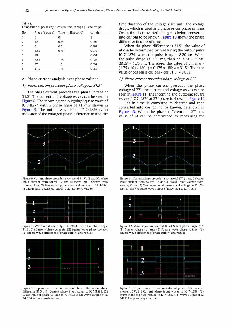
The phase current precedes the phase voltage of 31.5°. The current and voltage waves can be seen in Figure 8. The incoming and outgoing square wave of IC 74LS74 with a phase angle of 31.5° is shown in Figure 9. The output wave IC of IC 74LS86 is an indicator of the enlarged phase difference to find the
time duration of the voltage rises until the voltage drops, which is used as a phase or cos phase in time. Cos in time is converted to degrees before converted into cos phi to be known. Figure 10 shows the phase difference in units of time.
When the phase difference is 31.5°, the value of Δt can be determined by measuring the output pulse IC 74LS74, when the pulse is up at 8.20 ms. When the pulse drops at 9.90 ms, then Δt is Δt = 29.98-28.23 = 1.75 ms. Therefore, the value of phi is φ = (1.75 / 10) x 180; φ = 0.175 x 180; φ = 31.5°; Then the value of cos phi is cos phi = cos 31.5° = 0.852.
2) Phase current precedes phase voltage at 27°
When the phase current precedes the phase voltage of 27°, the current and voltage waves can be seen in Figure 11. The incoming and outgoing square wave of IC 74LS74 at 27° phase is shown in Figure 12.
Cos in time is converted to degrees and then converted into cos phi to be known, as shown in Figure 13. When the phase difference is 27°, the value of Δt can be determined by measuring the
Table 1. Comparison of phase angle (cos) in time, in angle (°) and cos phi
No Angle (degree) Time (millisecond) cos phi
1 0 0 1
2 4.5 0.25 0.997
3 9 0.5 0.987
4 13.5 0.75 0.972
5 18 1 0.951
6 22.5 1.25 0.923
7 27 1.5 0.891
8 31.5 1.75 0.852
Figure 8. Current phase precedes a voltage of 31.5°: (1 and 3): Wave input current from source; (2 and 4) Wave input voltage from source; (1 and 2) Sine wave input current and voltage to IC LM-324; (3 and 4) Square wave output of IC LM-324 to IC 74LS86
Figure 11. Current phase precedes a voltage of 27°. (1 and 3) Wave input current from source; (2 and 4) Wave input voltage from source; (1 and 2) Sine wave input current and voltage to IC LM-324; (3 and 4) Square wave output of IC LM-324 to IC 74LS86
Figure 9. Wave input and output IC 74LS86 with the phase angle 31.5°; (1) Current-phase currents; (2) Square wave phase voltage; (3) Square wave difference of phase current and voltage
Figure 12. Wave input and output IC 74LS86 at phase angle 27°. (1) Current-phase currents (2) Square wave phase voltage; (3) Square wave difference of phase current and voltage
Figure 10. Square wave as an indicator of phase difference at phase difference 31.5°: (1) Current phase input waves to IC 74LS86; (2) Wave input of phase voltage to IC 74LS86; (3) Wave output of IC 74LS86 as phase angle in time
Figure 13. Square wave as an indicator of phase difference at moment 27°. (1) Current phase input waves to IC 74LS86; (2) Wave input of phase voltage to IC 74LS86; (3) Wave output of IC 74LS86 as phase angle in time
Jumrianto and Royan / Journal of Mechatronics, Electrical Power, and Vehicular Technology 12 (2021) 28-37
33
output pulse IC 74LS74. When the pulse rises at 8.5 ms and drops at 10 ms, then Δt is Δt = 10 - 8.5 = 1.5 ms. Therefore, the value of phi is φ = (1.5 / 10) x 180; φ = 0.15 x 180; φ = 27°. Then the value of cos phi is cos phi = cos 27° = 0.891.
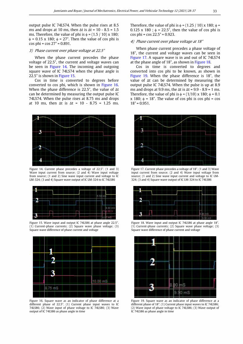
3) Phase current over phase voltage at 22.5°
When the phase current precedes the phase voltage of 22.5°, the current and voltage waves can be seen in Figure 14. The incoming and outgoing square wave of IC 74LS74 when the phase angle is 22.5° is shown in Figure 15.
Cos in time is converted to degrees before converted to cos phi, which is shown in Figure 16. When the phase difference is 22.5°, the value of Δt can be determined by measuring the output pulse IC 74LS74. When the pulse rises at 8.75 ms and drops at 10 ms, then Δt is Δt = 10 - 8.75 = 1.25 ms.
Therefore, the value of phi is φ = (1.25 / 10) x 180; φ = 0.125 x 180 ; φ = 22.5°, then the value of cos phi is cos phi = cos 22.5° = 0.923.
4) Phase current over phase voltage at 18°
When phase current precedes a phase voltage of 18°, the current and voltage waves can be seen in Figure 17. A square wave is in and out of IC 74LS74 at the phase angle of 18°, as shown in Figure 18.
Cos in time is converted to degrees and converted into cos phi to be known, as shown in Figure 19. When the phase difference is 18°, the value of Δt can be determined by measuring the output pulse IC 74LS74. When the pulse is up at 8.9 ms and drops at 9.9 ms, the Δt is Δt = 9.9 - 8.9 = 1 ms. Therefore, the value of phi is φ = (1/10) x 180; φ = 0.1 x 180; φ = 18°. The value of cos phi is cos phi = cos 18° = 0.951.
Figure 14. Current phase precedes a voltage of 22.5°. (1 and 3) Wave input current from source; (2 and 4) Wave input voltage from source; (1 and 2) Sine wave input current and voltage to IC LM-324; (3 and 4) Square wave output of IC LM-324 to IC 74LS86
Figure 17. Current phase precedes a voltage of 18°. (1 and 3) Wave input current from source; (2 and 4) Wave input voltage from source; (1 and 2) Sine wave input current and voltage to IC LM-324; (3 and 4) Square wave output of IC LM-324 to IC 74LS86
Figure 15. Wave input and output IC 74LS86 at phase angle 22.5°. (1) Current-phase currents; (2) Square wave phase voltage; (3) Square wave difference of phase current and voltage
Figure 18. Wave input and output IC 74LS86 at phase angle 18°. (1) Current-phase currents; (2) Square wave phase voltage; (3) Square wave difference of phase current and voltage
Figure 16. Square wave as an indicator of phase difference at a different phase of 22.5°. (1) Current phase input waves to IC 74LS86; (2) Wave input of phase voltage to IC 74LS86; (3) Wave output of IC 74LS86 as phase angle in time
Figure 19. Square wave as an indicator of phase difference at a different phase of 18°. (1) Current phase input waves to IC 74LS86; (2) Wave input of phase voltage to IC 74LS86; (3) Wave output of IC 74LS86 as phase angle in time
Jumrianto and Royan / Journal of Mechatronics, Electrical Power, and Vehicular Technology 12 (2021) 28-37
34
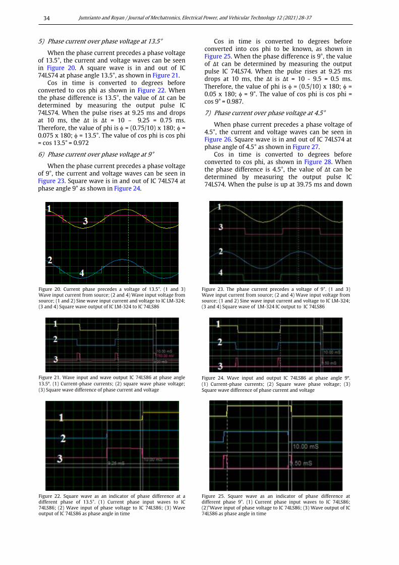
5) Phase current over phase voltage at 13.5°
When the phase current precedes a phase voltage of 13.5°, the current and voltage waves can be seen in Figure 20. A square wave is in and out of IC 74LS74 at phase angle 13.5°, as shown in Figure 21.
Cos in time is converted to degrees before converted to cos phi as shown in Figure 22. When the phase difference is 13.5°, the value of Δt can be determined by measuring the output pulse IC 74LS74. When the pulse rises at 9.25 ms and drops at 10 ms, the Δt is Δt = 10 – 9.25 = 0.75 ms. Therefore, the value of phi is φ = (0.75/10) x 180; φ = 0.075 x 180; φ = 13.5°. The value of cos phi is cos phi = cos 13.5° = 0.972
6) Phase current over phase voltage at 9°
When the phase current precedes a phase voltage of 9°, the current and voltage waves can be seen in Figure 23. Square wave is in and out of IC 74LS74 at phase angle 9° as shown in Figure 24.
Cos in time is converted to degrees before converted into cos phi to be known, as shown in Figure 25. When the phase difference is 9°, the value of Δt can be determined by measuring the output pulse IC 74LS74. When the pulse rises at 9.25 ms drops at 10 ms, the Δt is Δt = 10 - 9.5 = 0.5 ms. Therefore, the value of phi is φ = (0.5/10) x 180; φ = 0.05 x 180; φ = 9°. The value of cos phi is cos phi = cos 9° = 0.987.
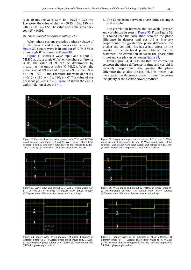
7) Phase current over phase voltage at 4.5°
When phase current precedes a phase voltage of 4.5°, the current and voltage waves can be seen in Figure 26. Square wave is in and out of IC 74LS74 at phase angle of 4.5° as shown in Figure 27.
Cos in time is converted to degrees before converted to cos phi, as shown in Figure 28. When the phase difference is 4.5°, the value of Δt can be determined by measuring the output pulse IC 74LS74. When the pulse is up at 39.75 ms and down
Figure 20. Current phase precedes a voltage of 13.5°. (1 and 3) Wave input current from source; (2 and 4) Wave input voltage from source; (1 and 2) Sine wave input current and voltage to IC LM-324; (3 and 4) Square wave output of IC LM-324 to IC 74LS86
Figure 23. The phase current precedes a voltage of 9°. (1 and 3) Wave input current from source; (2 and 4) Wave input voltage from source; (1 and 2) Sine wave input current and voltage to IC LM-324; (3 and 4) Square wave of LM-324 IC output to IC 74LS86
Figure 21. Wave input and wave output IC 74LS86 at phase angle 13.5º. (1) Current-phase currents; (2) square wave phase voltage; (3) Square wave difference of phase current and voltage
Figure 24. Wave input and output IC 74LS86 at phase angle 9º. (1) Current-phase currents; (2) Square wave phase voltage; (3) Square wave difference of phase current and voltage
Figure 22. Square wave as an indicator of phase difference at a different phase of 13.5°. (1) Current phase input waves to IC 74LS86; (2) Wave input of phase voltage to IC 74LS86; (3) Wave output of IC 74LS86 as phase angle in time
Figure 25. Square wave as an indicator of phase difference at different phase 9°. (1) Current phase input waves to IC 74LS86; (2)°Wave input of phase voltage to IC 74LS86; (3) Wave output of IC 74LS86 as phase angle in time
Jumrianto and Royan / Journal of Mechatronics, Electrical Power, and Vehicular Technology 12 (2021) 28-37
35
is at 40 ms, the Δt is Δt = 40 - 39.75 = 0.25 ms. Therefore, the value of phi is φ = (0.25 / 10) x 180; φ = 0.025 x 180; φ = 4.5°. The value of cos phi is cos phi = cos 4.5° = 0.996.
8) Phase current over phase voltage at 0°
When phase current precedes a phase voltage of 0°, the current and voltage waves can be seen in Figure 29. Square wave is in and out of IC 74LS74 at phase angle 0° as shown in Figure 30.
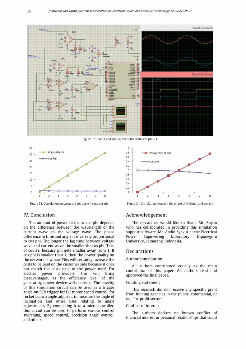
Figure 31 shows a wave input and output IC 74LS86 at phase angle 0°. When the phase difference is 0°, the value of Δt can be determined by measuring the output pulse IC 74LS74. When the pulse is up at 9.9 ms and drops at 9.9 ms, then Δt is Δt = 9.9 – 9.9 = 0 ms. Therefore, the value of phi is φ = (0/10) x 180; φ = 0 x 180; φ = 0°. The value of cos phi is cos phi = cos 0° = 1. Figure 32 shows the circuit and simulation of cos phi = 1.
B. The Correlation between phase shift, cos angle, and cos phi
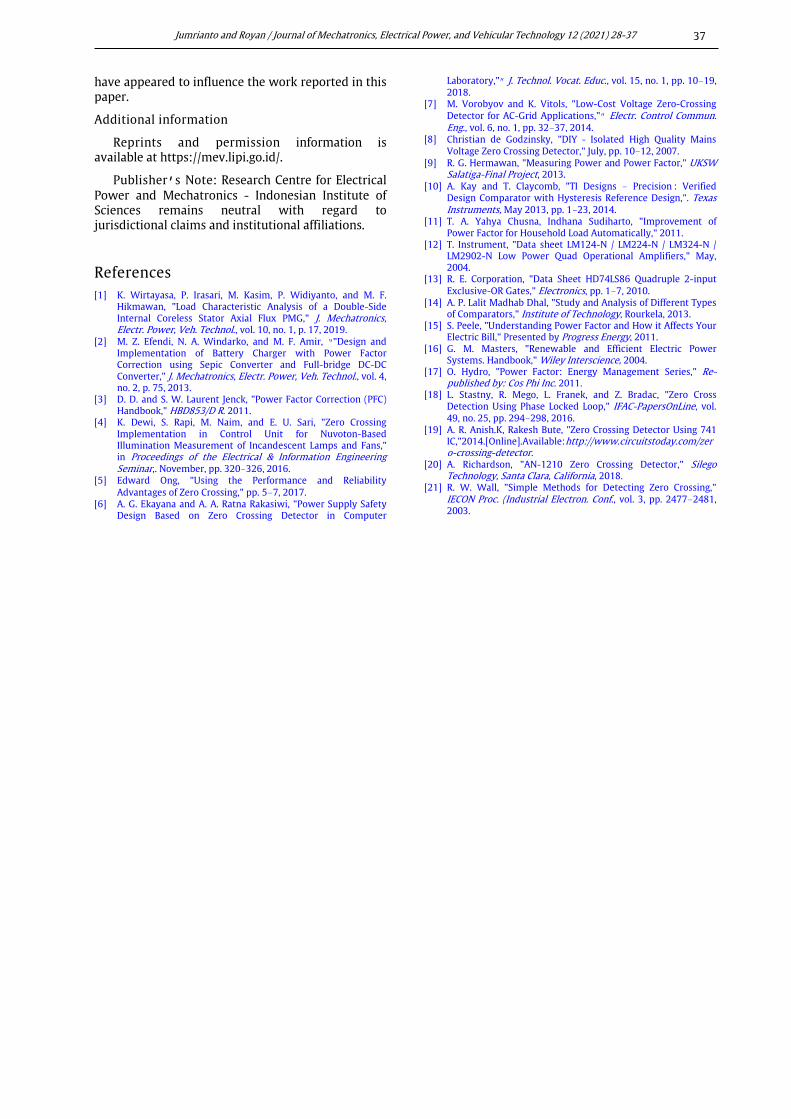
The correlation between the cos angle (degree) and cos phi can be seen in Figure 33. From Figure 33, it is found that the correlation between the phase difference in degrees and cos phi is inversely proportional; the greater the phase difference, the smaller the cos phi. This has a bad effect on the quality of the electrical power obtained by the customer. The correlation between the phase shift (time) and cos phi can be seen in Figure 34.
From Figure 34, it is found that the correlation between the phase difference in time and cos phi is inversely proportional; the greater the phase difference the smaller the cos phi. This means that the greater the difference phase in time, the worse the quality of the electric power produced.
Figure 26. Current phase precedes a voltage of 4.5°. (1 and 3) Wave input current from source; (2 and 4): Wave input voltage from source; (1 and 2) Sine wave input current and voltage to IC LM-324; (3 and 4) Square wave of LM-324 IC output to IC 74LS86
Figure 29. Current phase precedes a voltage of 0°. (1 and 3) Wave input current from source; (2 and 4) Wave input voltage from source; (1 and 2) Sine wave input current and voltage to IC LM-324; (3 and 4) Square wave output of IC LM-324 to IC 74LS86
Figure 27. Wave input and output IC 74LS86 at phase angle 4.5°. (1)° Current-phase currents; (2) Square wave phase voltage; (3)°Square wave difference of phase current and voltage
Figure 30. Wave input and output IC 74LS86 at phase angle 0°. (1)°Current-phase currents; (2) Square wave phase voltage; (3)°Square wave difference of phase current and voltage
Figure 28. Square wave as an indicator of phase difference at different phase 4.5°. (1) Current phase input waves to IC 74LS86; (2) Wave input of phase voltage to IC 74LS86; (3) Wave output of IC 74LS86 as phase angle in time
Figure 31. Square wave as an indicator of phase difference at different phase 0°. (1) Current phase input waves to IC 74LS86; (2)°Wave input of phase voltage to IC 74LS86; (3) Wave output of IC 74LS86 as phase angle in time
Jumrianto and Royan / Journal of Mechatronics, Electrical Power, and Vehicular Technology 12 (2021) 28-37
36
IV. Conclusion
The amount of power factor or cos phi depends on the difference between the wavelength of the current wave to the voltage wave. The phase difference in time and angle is inversely proportional to cos phi. The longer the lag time between voltage wave and current wave, the smaller the cos phi. This, of course, because phi gets smaller away from 1. If cos phi is smaller than 1, then the power quality on the network is worse. This will certainly increase the costs to be paid on the customer side because it does not match the costs paid to the power used. For electric power providers, this will bring disadvantages, as the efficiency level of the generating power device will decrease. The novelty of this simulation circuit can be used as a trigger angle on SCR trigger for DC motor speed control, for rocket launch angle adjuster, to measure the angle of inclination and other uses relating to angle adjustments. By connecting it to a microcontroller, this circuit can be used to perform various control switching, speed control, precision angle control, and others.
Acknowledgement
The researcher would like to thank Mr. Royan who has collaborated in providing this simulation support software, Mr. Abdul Syakur at the Electrical Power Engineering Laboratory, Diponegoro University, Semarang, Indonesia.
Declarations
Author contribution
All authors contributed equally as the main contributor of this paper. All authors read and approved the final paper.
Funding statement
This research did not receive any specific grant from funding agencies in the public, commercial, or not-for-profit sectors.
Conflict of interest
The authors declare no known conflict of financial interest or personal relationships that could
Figure 32. Circuit and simulation of the value cos phi = 1
Figure 33. Correlation between the cos angle (º) and cos phi Figure 34. Correlation between the phase shift (time) and cos phi
0
5
10
15
20
25
30
35
1 2 3 4 5 6 7 8
Angle (degree)
Cos Phi
00.20.40.60.8
11.21.41.61.8
2
1 2 3 4 5 6 7 8
Phase Shift (time)
Cos Phi
Jumrianto and Royan / Journal of Mechatronics, Electrical Power, and Vehicular Technology 12 (2021) 28-37
37
have appeared to influence the work reported in this paper.
Additional information
Reprints and permission information is available at https://mev.lipi.go.id/.
Publisher’s Note: Research Centre for Electrical Power and Mechatronics - Indonesian Institute of Sciences remains neutral with regard to jurisdictional claims and institutional affiliations.
References [1] K. Wirtayasa, P. Irasari, M. Kasim, P. Widiyanto, and M. F.
Hikmawan, "Load Characteristic Analysis of a Double-Side Internal Coreless Stator Axial Flux PMG," J. Mechatronics, Electr. Power, Veh. Technol., vol. 10, no. 1, p. 17, 2019.
[2] M. Z. Efendi, N. A. Windarko, and M. F. Amir, “"Design and Implementation of Battery Charger with Power Factor Correction using Sepic Converter and Full-bridge DC-DC Converter," J. Mechatronics, Electr. Power, Veh. Technol., vol. 4, no. 2, p. 75, 2013.
[3] D. D. and S. W. Laurent Jenck, "Power Factor Correction (PFC) Handbook," HBD853/D R. 2011.
[4] K. Dewi, S. Rapi, M. Naim, and E. U. Sari, "Zero Crossing Implementation in Control Unit for Nuvoton-Based Illumination Measurement of Incandescent Lamps and Fans," in Proceedings of the Electrical & Information Engineering Seminar,. November, pp. 320–326, 2016.
[5] Edward Ong, "Using the Performance and Reliability Advantages of Zero Crossing," pp. 5–7, 2017.
[6] A. G. Ekayana and A. A. Ratna Rakasiwi, "Power Supply Safety Design Based on Zero Crossing Detector in Computer
Laboratory,"” J. Technol. Vocat. Educ., vol. 15, no. 1, pp. 10–19, 2018.
[7] M. Vorobyov and K. Vitols, "Low-Cost Voltage Zero-Crossing Detector for AC-Grid Applications,"” Electr. Control Commun. Eng., vol. 6, no. 1, pp. 32–37, 2014.
[8] Christian de Godzinsky, "DIY - Isolated High Quality Mains Voltage Zero Crossing Detector," July, pp. 10–12, 2007.
[9] R. G. Hermawan, "Measuring Power and Power Factor," UKSW Salatiga-Final Project, 2013.
[10] A. Kay and T. Claycomb, "TI Designs – Precision : Verified Design Comparator with Hysteresis Reference Design,". Texas Instruments, May 2013, pp. 1–23, 2014.
[11] T. A. Yahya Chusna, Indhana Sudiharto, "Improvement of Power Factor for Household Load Automatically," 2011.
[12] T. Instrument, "Data sheet LM124-N / LM224-N / LM324-N / LM2902-N Low Power Quad Operational Amplifiers," May, 2004.
[13] R. E. Corporation, "Data Sheet HD74LS86 Quadruple 2-input Exclusive-OR Gates," Electronics, pp. 1–7, 2010.
[14] A. P. Lalit Madhab Dhal, "Study and Analysis of Different Types of Comparators," Institute of Technology, Rourkela, 2013.
[15] S. Peele, "Understanding Power Factor and How it Affects Your Electric Bill," Presented by Progress Energy, 2011.
[16] G. M. Masters, "Renewable and Efficient Electric Power Systems. Handbook," Wiley Interscience, 2004.
[17] O. Hydro, "Power Factor: Energy Management Series," Re-published by: Cos Phi Inc. 2011.
[18] L. Stastny, R. Mego, L. Franek, and Z. Bradac, "Zero Cross Detection Using Phase Locked Loop," IFAC-PapersOnLine, vol. 49, no. 25, pp. 294–298, 2016.
[19] A. R. Anish.K, Rakesh Bute, "Zero Crossing Detector Using 741 IC,"2014.[Online].Available:http://www.circuitstoday.com/zero-crossing-detector.
[20] A. Richardson, "AN-1210 Zero Crossing Detector," Silego Technology, Santa Clara, California, 2018.
[21] R. W. Wall, "Simple Methods for Detecting Zero Crossing," IECON Proc. (Industrial Electron. Conf., vol. 3, pp. 2477–2481, 2003.
Related Documents