Protein-DNA interactions define the mechanistic aspects of circle formation and insertion reactions in IS2 transposition Lewis et al. Lewis et al. Mobile DNA 2012, 3:1 http://www.mobilednajournal.com/content/3/1/1 (26 January 2012)

Welcome message from author
This document is posted to help you gain knowledge. Please leave a comment to let me know what you think about it! Share it to your friends and learn new things together.
Transcript
Protein-DNA interactions define the mechanisticaspects of circle formation and insertion reactionsin IS2 transpositionLewis et al.
Lewis et al. Mobile DNA 2012, 3:1http://www.mobilednajournal.com/content/3/1/1 (26 January 2012)
RESEARCH Open Access
Protein-DNA interactions define the mechanisticaspects of circle formation and insertion reactionsin IS2 transpositionLeslie A Lewis1,2*, Mekbib Astatke3, Peter T Umekubo1,4, Shaheen Alvi1,5, Robert Saby1,6, Jehan Afrose1,7,Pedro H Oliveira8,9, Gabriel A Monteiro8,9 and Duarte MF Prazeres8,9
Abstract
Background: Transposition in IS3, IS30, IS21 and IS256 insertion sequence (IS) families utilizes an unconventionaltwo-step pathway. A figure-of-eight intermediate in Step I, from asymmetric single-strand cleavage and joiningreactions, is converted into a double-stranded minicircle whose junction (the abutted left and right ends) is thesubstrate for symmetrical transesterification attacks on target DNA in Step II, suggesting intrinsically differentsynaptic complexes (SC) for each step. Transposases of these ISs bind poorly to cognate DNA and comparativebiophysical analyses of SC I and SC II have proven elusive. We have prepared a native, soluble, active, GFP-taggedfusion derivative of the IS2 transposase that creates fully formed complexes with single-end and minicircle junction(MCJ) substrates and used these successfully in hydroxyl radical footprinting experiments.
Results: In IS2, Step I reactions are physically and chemically asymmetric; the left imperfect, inverted repeat (IRL),the exclusive recipient end, lacks donor function. In SC I, different protection patterns of the cleavage domains(CDs) of the right imperfect inverted repeat (IRR; extensive in cis) and IRL (selective in trans) at the single activecognate IRR catalytic center (CC) are related to their donor and recipient functions. In SC II, extensive binding ofthe IRL CD in trans and of the abutted IRR CD in cis at this CC represents the first phase of the complex. An MCJsubstrate precleaved at the 3’ end of IRR revealed a temporary transition state with the IRL CD disengaged fromthe protein. We propose that in SC II, sequential 3’ cleavages at the bound abutted CDs trigger a conformationalchange, allowing the IRL CD to complex to its cognate CC, producing the second phase. Corroborating data fromenhanced residues and curvature propensity plots suggest that CD to CD interactions in SC I and SC II require IRLto assume a bent structure, to facilitate binding in trans.
Conclusions: Different transpososomes are assembled in each step of the IS2 transposition pathway. Recipientversus donor end functions of the IRL CD in SC I and SC II and the conformational change in SC II that producesthe phase needed for symmetrical IRL and IRR donor attacks on target DNA highlight the differences.
Keywords: Curvature propensity plot data, extensive sequence-specific binding, figure-of-eight transposition inter-mediate, hydroxyl radical footprinting, minicircle junction, selective binding, synaptic complex, transpososome
BackgroundIS2, a 1.3 kb transposable element, is a member of thelarge and widespread IS3 family of insertion sequences(IS) ([1,2] see also ISfinder: http://www-is.biotoul.fr/is.html). Transposition mechanisms in the IS3 family can
be described as a two-step copy-and-paste process [3], incontrast to both classical cut-and-paste and replicativeparadigms [4-6]. Although transposases of two IS3 familymembers, IS911 [7-9] and IS2 [10,11] were originallyshown to facilitate transposition by catalyzing the twodistinct reactions whose steps are shown in Figure 1A,there is strong evidence for the existence of this pathwayin other IS3 family members such as IS3 [12,13] andIS150 [14] as well as for its more widespread use in the
* Correspondence: [email protected] of Biology, York College of the City University of New York,Jamaica, New York 11451, USAFull list of author information is available at the end of the article
Lewis et al. Mobile DNA 2012, 3:1http://www.mobilednajournal.com/content/3/1/1
© 2012 Lewis et al; licensee BioMed Central Ltd. This is an Open Access article distributed under the terms of the Creative CommonsAttribution License (http://creativecommons.org/licenses/by/2.0), which permits unrestricted use, distribution, and reproduction inany medium, provided the original work is properly cited.
IS30 [15,16], IS21 [17] and IS256 [18] families of inser-tion sequences. In general in these families, Step Iinvolves a cleavage and joining reaction between theends, one of which (the optional donor) is cleaved andparticipates in an asymmetric, intrastrand, strand-transferreaction to a phosphodiester bond in host DNA near theother end (the recipient). The product is a branchedstructure, the figure-of-eight (F-8) transposition inter-mediate [7,11,16] in which two abutted single-strandedends are separated by an interstitial spacer of one ormore bases. The F-8 is then converted by host cell repli-cation mechanisms [3] to a covalently closed double-stranded transposition intermediate, the minicircle,(Figure 1A) whose abutted ends, separated by the spacer,comprise a reactive junction, the minicircle junction(MCJ). Minicircle insertion into the target occurs in StepII (Figure 1A) and requires that both ends function asdonors [10,19]. Here, the reactive junction is the sub-strate for strand transfer reactions: it is cleaved at theabutted termini of the ends, creating 3’OH groups whichundergo symmetrical transesterification attacks on targetDNA. This results in the insertion of the element flankedby its direct repeats; see Rousseau et al., [2] for a detailedreview.The ends of IS2 are 41 bp and 42 bp right and left
imperfect inverted repeats (IRR and IRL; Figure 1B)respectively; between these ends the IS encodes two over-lapping reading frames, OrfA and OrfB (Figure 1B, i).OrfA is a 14 kDa protein which has been reported in IS2[20] to bind to a sequence just upstream of the weakindigenous extended-10 promoter (PIRL-[10]) located justinside the left end (IRL) of the element (Figure 1C, ii).This weak promoter regulates the expression of IS2 pro-teins in Step I. The function of OrfB is unknown but afusion protein OrfAB, the functional transposase (TPase),is generated by programmed -1 translational frameshift-ing [13,21,22] at a sequence of slippery codons (the A6Gframeshift window in IS2), located near the 3’ end of orfA(Figure 1B, i). Mutation of this window to A7G in IS2(Figure 1B, ii) produces OrfAB as the predominant spe-cies [11,23]. When the IS2 ends are aligned (Figure 1C, i,ii), they show four non-conserved elements (I, A, B andC) and two conserved elements (II and III) which playcritical roles in the transposition mechanism. Elements Aand I comprise a cleavage domain (CD) and B, II, C andIII, a protein binding domain (PBD). The differences inthe sequences of the two ends are related to their donorand recipient end functions (see below) in Step I [24].Several features distinguish circle formation and its con-
sequences in IS2 from those in other IS3 family members.The reaction is physically as well as chemically asymmetricin that the right end functions uniquely as the donor ortransferred end and the left end serves exclusively as thefunctional recipient end. This asymmetry is not unique to
IS2, having also been demonstrated in copies of IS256 inTn4001 [18]. Recipient end function in IS2 is partiallydefined by the accuracy with which the joining reactionoccurs. Abutted ends at the MCJ (Figure 1C, iii) are sepa-rated by a one or two base pair spacer with a ratio of 90%to 10% [11,24] but functional minicircles are limited tothose with a single base pair spacer. This is so becausecreation of the MCJ in IS2 assembles a promoter, Pjunc,[25] which has an absolute requirement for a 17-nucleo-tide promoter spacer (Figure 1C, i, ii) that is conferred bythe one base pair MCJ spacer. This more powerful Pjunc isessential for and drives transposase reactions in Step II[10]. MCJ promoters with spacers of two or more basepairs are completely non-functional.We concluded from earlier studies that differences in
length and sequence of the two ends of IS2 in Step I areresponsible for the restriction of donor and recipient endfunctions to IRR and IRL respectively [24]. Differences inlength are related to the correct positioning of theshorter donor end (IRR) in the catalytic pocket. However,random mutation in the A element of the AIRR sequencein an IRR CD eliminated minicircle production, whilesimilar changes in AIRL in an IRL CD had no effect onthe efficiency of minicircle formation; this result impliedthat extensive sequence-specific protein affinity for the Aelement was important in defining donor function butnot recipient end function. For the B element, mutationsin the BIRR sequence also eliminated minicircle forma-tion, implicating sequence-specific protein affinity. Addi-tional domain swapping experiments involved thesubstitution of a 6 bp BIRL sequence in an IRR derivative,which did not change the length of IRR (Figure 1C, i and1C, ii). This reduced but did not eliminate IRR donoractivity, implying that the protein had a weaker affinityfor BIRL. Further evidence for some protein interactionwith the BIRL sequence is that in IRL, its mutation (a tri-plet of point mutations) all but eliminated minicircle for-mation. These results suggested that the degree ofsequence-specific interaction of the protein for sequencesin or near the CDs may also be related to donor and reci-pient end functions; in an IRR end, extensive interactionof the protein with AIRR and BIRR would be required forthe donor function; however, in IRL the lack of extensiveinteraction of the protein with AIRL and a weak affinityfor BIRL may contribute to recipient end identity.Additional data from experiments with AIRL threw
light on this supposition. First, in an IS2 mutant withtwo IRR ends, the increase in length of one IRR by asingle base pair alone was necessary and sufficient toconvert it to a recipient end with no donor function.However, the addition of AIRL was absolutely essentialfor the accuracy of recipient end function. Furthermore,alteration of any one of three non-conserved nucleotidesin positions 2, 5 and 7 in AIRL (Figure 1C, ii) that made
Lewis et al. Mobile DNA 2012, 3:1http://www.mobilednajournal.com/content/3/1/1
Page 2 of 24
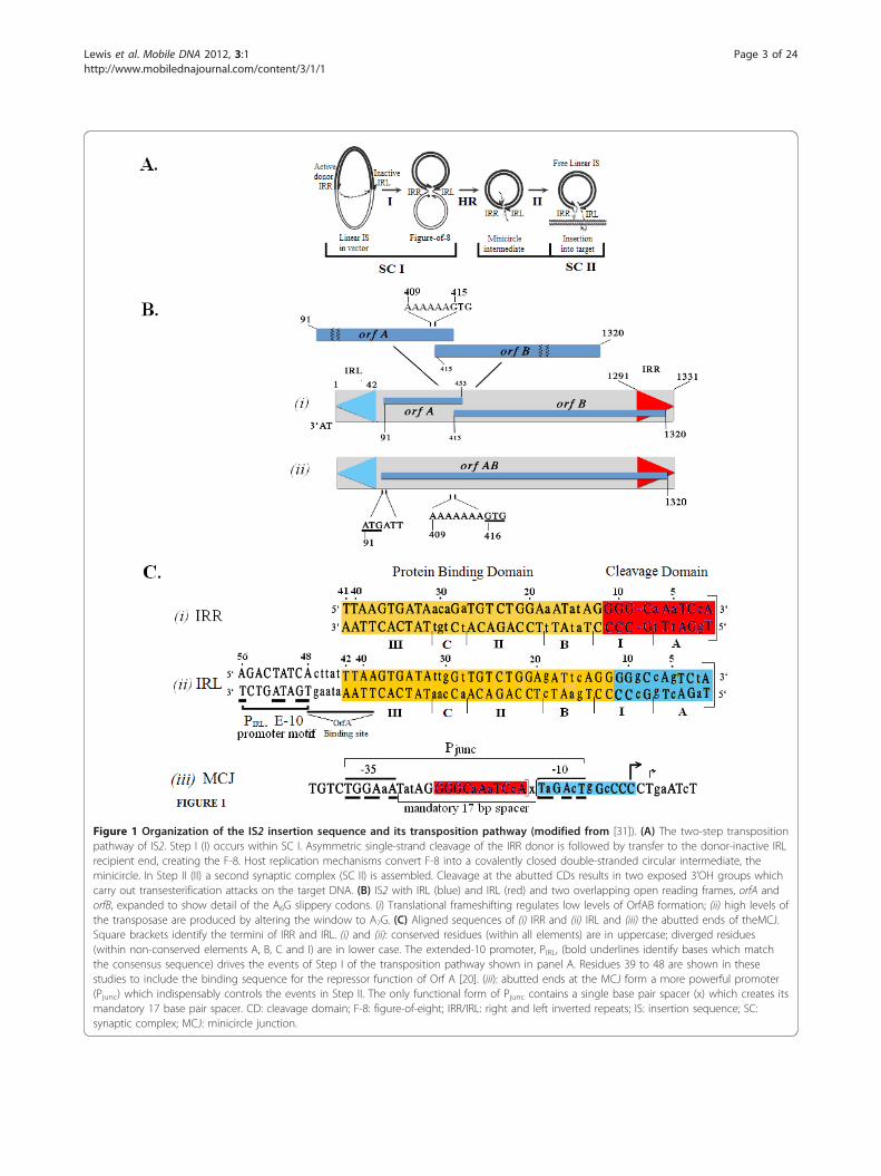
Figure 1 Organization of the IS2 insertion sequence and its transposition pathway (modified from [31]). (A) The two-step transpositionpathway of IS2. Step I (I) occurs within SC I. Asymmetric single-strand cleavage of the IRR donor is followed by transfer to the donor-inactive IRLrecipient end, creating the F-8. Host replication mechanisms convert F-8 into a covalently closed double-stranded circular intermediate, theminicircle. In Step II (II) a second synaptic complex (SC II) is assembled. Cleavage at the abutted CDs results in two exposed 3’OH groups whichcarry out transesterification attacks on the target DNA. (B) IS2 with IRL (blue) and IRL (red) and two overlapping open reading frames, orfA andorfB, expanded to show detail of the A6G slippery codons. (i) Translational frameshifting regulates low levels of OrfAB formation; (ii) high levels ofthe transposase are produced by altering the window to A7G. (C) Aligned sequences of (i) IRR and (ii) IRL and (iii) the abutted ends of theMCJ.Square brackets identify the termini of IRR and IRL. (i) and (ii): conserved residues (within all elements) are in uppercase; diverged residues(within non-conserved elements A, B, C and I) are in lower case. The extended-10 promoter, PIRL, (bold underlines identify bases which matchthe consensus sequence) drives the events of Step I of the transposition pathway shown in panel A. Residues 39 to 48 are shown in thesestudies to include the binding sequence for the repressor function of Orf A [20]. (iii): abutted ends at the MCJ form a more powerful promoter(Pjunc) which indispensably controls the events in Step II. The only functional form of Pjunc contains a single base pair spacer (x) which creates itsmandatory 17 base pair spacer. CD: cleavage domain; F-8: figure-of-eight; IRR/IRL: right and left inverted repeats; IS: insertion sequence; SC:synaptic complex; MCJ: minicircle junction.
Lewis et al. Mobile DNA 2012, 3:1http://www.mobilednajournal.com/content/3/1/1
Page 3 of 24
the sequence more like that of the IRR CD reduced theaccuracy of the joining reaction in Step I by increasingMCJ spacer size. We posited then, that the non-con-served base pairs in AIRL, through some interaction withthe protein, were responsible for the accuracy of recipi-ent end function by correctly positioning the IRL CD intrans in the vicinity of the IRR CD to generate a singleinterstitial base pair between the abutted ends. (See theResults and discussion section for a complete analysis ofall factors which define recipient end function.) It isinteresting that mutation of position 2 of IRL, whichconverted the TA3’ terminal dinucleotide to the CA3’consensus in the IS3 family, did not confer functionaldonor activity on IRL [24], due, among other factors, toits incorrect positioning in the cognate catalytic center(CC). Finally, although the features described above forIRL define its accuracy as a recipient end, the sequenceof the flanking host DNA can also play a role in deter-mining spacer size [24], implying that the host DNAsequence adjacent to IRL is also involved in some kindof interaction with the TPase.Mechanistically, in elements with F-8 transposition
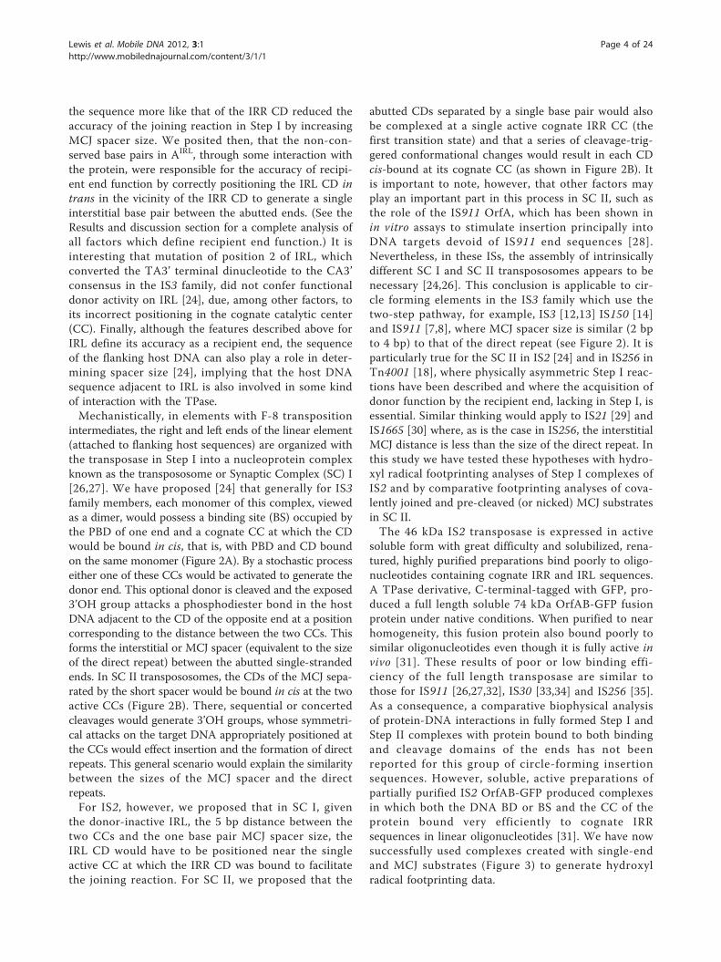
intermediates, the right and left ends of the linear element(attached to flanking host sequences) are organized withthe transposase in Step I into a nucleoprotein complexknown as the transpososome or Synaptic Complex (SC) I[26,27]. We have proposed [24] that generally for IS3family members, each monomer of this complex, viewedas a dimer, would possess a binding site (BS) occupied bythe PBD of one end and a cognate CC at which the CDwould be bound in cis, that is, with PBD and CD boundon the same monomer (Figure 2A). By a stochastic processeither one of these CCs would be activated to generate thedonor end. This optional donor is cleaved and the exposed3’OH group attacks a phosphodiester bond in the hostDNA adjacent to the CD of the opposite end at a positioncorresponding to the distance between the two CCs. Thisforms the interstitial or MCJ spacer (equivalent to the sizeof the direct repeat) between the abutted single-strandedends. In SC II transpososomes, the CDs of the MCJ sepa-rated by the short spacer would be bound in cis at the twoactive CCs (Figure 2B). There, sequential or concertedcleavages would generate 3’OH groups, whose symmetri-cal attacks on the target DNA appropriately positioned atthe CCs would effect insertion and the formation of directrepeats. This general scenario would explain the similaritybetween the sizes of the MCJ spacer and the directrepeats.For IS2, however, we proposed that in SC I, given
the donor-inactive IRL, the 5 bp distance between thetwo CCs and the one base pair MCJ spacer size, theIRL CD would have to be positioned near the singleactive CC at which the IRR CD was bound to facilitatethe joining reaction. For SC II, we proposed that the
abutted CDs separated by a single base pair would alsobe complexed at a single active cognate IRR CC (thefirst transition state) and that a series of cleavage-trig-gered conformational changes would result in each CDcis-bound at its cognate CC (as shown in Figure 2B). Itis important to note, however, that other factors mayplay an important part in this process in SC II, such asthe role of the IS911 OrfA, which has been shown inin vitro assays to stimulate insertion principally intoDNA targets devoid of IS911 end sequences [28].Nevertheless, in these ISs, the assembly of intrinsicallydifferent SC I and SC II transpososomes appears to benecessary [24,26]. This conclusion is applicable to cir-cle forming elements in the IS3 family which use thetwo-step pathway, for example, IS3 [12,13] IS150 [14]and IS911 [7,8], where MCJ spacer size is similar (2 bpto 4 bp) to that of the direct repeat (see Figure 2). It isparticularly true for the SC II in IS2 [24] and in IS256 inTn4001 [18], where physically asymmetric Step I reac-tions have been described and where the acquisition ofdonor function by the recipient end, lacking in Step I, isessential. Similar thinking would apply to IS21 [29] andIS1665 [30] where, as is the case in IS256, the interstitialMCJ distance is less than the size of the direct repeat. Inthis study we have tested these hypotheses with hydro-xyl radical footprinting analyses of Step I complexes ofIS2 and by comparative footprinting analyses of cova-lently joined and pre-cleaved (or nicked) MCJ substratesin SC II.The 46 kDa IS2 transposase is expressed in active
soluble form with great difficulty and solubilized, rena-tured, highly purified preparations bind poorly to oligo-nucleotides containing cognate IRR and IRL sequences.A TPase derivative, C-terminal-tagged with GFP, pro-duced a full length soluble 74 kDa OrfAB-GFP fusionprotein under native conditions. When purified to nearhomogeneity, this fusion protein also bound poorly tosimilar oligonucleotides even though it is fully active invivo [31]. These results of poor or low binding effi-ciency of the full length transposase are similar tothose for IS911 [26,27,32], IS30 [33,34] and IS256 [35].As a consequence, a comparative biophysical analysisof protein-DNA interactions in fully formed Step I andStep II complexes with protein bound to both bindingand cleavage domains of the ends has not beenreported for this group of circle-forming insertionsequences. However, soluble, active preparations ofpartially purified IS2 OrfAB-GFP produced complexesin which both the DNA BD or BS and the CC of theprotein bound very efficiently to cognate IRRsequences in linear oligonucleotides [31]. We have nowsuccessfully used complexes created with single-endand MCJ substrates (Figure 3) to generate hydroxylradical footprinting data.
Lewis et al. Mobile DNA 2012, 3:1http://www.mobilednajournal.com/content/3/1/1
Page 4 of 24
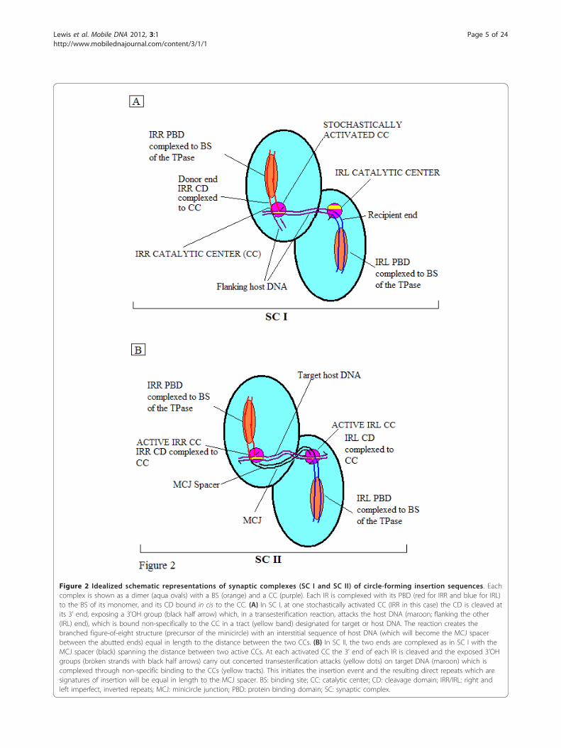
Figure 2 Idealized schematic representations of synaptic complexes (SC I and SC II) of circle-forming insertion sequences. Eachcomplex is shown as a dimer (aqua ovals) with a BS (orange) and a CC (purple). Each IR is complexed with its PBD (red for IRR and blue for IRL)to the BS of its monomer, and its CD bound in cis to the CC. (A) In SC I, at one stochastically activated CC (IRR in this case) the CD is cleaved atits 3’ end, exposing a 3’OH group (black half arrow) which, in a transesterification reaction, attacks the host DNA (maroon; flanking the other(IRL) end), which is bound non-specifically to the CC in a tract (yellow band) designated for target or host DNA. The reaction creates thebranched figure-of-eight structure (precursor of the minicircle) with an interstitial sequence of host DNA (which will become the MCJ spacerbetween the abutted ends) equal in length to the distance between the two CCs. (B) In SC II, the two ends are complexed as in SC I with theMCJ spacer (black) spanning the distance between two active CCs. At each activated CC the 3’ end of each IR is cleaved and the exposed 3’OHgroups (broken strands with black half arrows) carry out concerted transesterification attacks (yellow dots) on target DNA (maroon) which iscomplexed through non-specific binding to the CCs (yellow tracts). This initiates the insertion event and the resulting direct repeats which aresignatures of insertion will be equal in length to the MCJ spacer. BS: binding site; CC: catalytic center; CD: cleavage domain; IRR/IRL: right andleft imperfect, inverted repeats; MCJ: minicircle junction; PBD: protein binding domain; SC: synaptic complex.
Lewis et al. Mobile DNA 2012, 3:1http://www.mobilednajournal.com/content/3/1/1
Page 5 of 24
We show here that the footprinting patterns of bothIRR and IRL single ends of IS2 reveal bipartite structures.They differ in that the IRR CD is strongly and extensivelyprotected while the IRL CD is only selectively or inter-mittently bound by the protein. We propose a model inwhich non-specific and/or selective binding to the adja-cent host sequence and selective binding to the IRL CDact additively in SC I to promote binding of the IRL CDin trans at the active cognate IRR CC. In SC II, extensiveprotection of both the IRL and the abutted IRR CDs,separated by a single base pair, suggests binding at a sin-gle active cognate IRR CC with the IRL CD bound intrans, creating the first phase of the SC. Our data suggestthat sequential cleavages (associated with small confor-mational changes) at the 3’ termini of IRR and IRL at thisactive CC trigger a conformational change that leads totransition to a second phase; that is, each CD complexedin cis to its own active cognate CC. In addition, the loca-tion of enhanced residues indicative of distortion orbending of DNA, corroborated by curvature propensityplot data, have helped gain insight into the paths of theIRL DNA which facilitate binding in trans within thearchitecture of SC I and SC II transpososomes.
Results and discussionFootprinting the single ends of IS2Hydroxyl radical footprinting was carried out using 87bp (R87) and 79 bp (L79) radio-labeled dsDNA sub-strates containing the 41 bp sequence of IRR and the42 bp sequence of IRL, respectively. The substrates wereprepared as annealed oligonucleotides with the labeledstrand as the footprinting target (see the Methods sec-tion). The transposase was overexpressed from pLL2522,the plasmid with the orfAB::GFP fusion construct, andpartially purified by nickel-nitrilotriacetic acid (Ni-NTA)affinity chromatography [31]. Mutational studies withthis partially purified protein (specifically null mutantswith a complete loss of binding proficiency), indicatedstrongly that the observed binding reactions did notresult from trace amounts of the IS2 Tpase from chro-mosomal copies of the element. In addition, two sets ofresults suggest that the presence of the GFP tag affectedneither the binding properties nor the activity of OrfAB.First, in vivo transposition frequencies of the tagged pro-tein are statistically identical to those of the native pro-tein [31]; secondly, in a cleavage assay [36], complexesformed in-gel with a mixture of 87-mer IRR and 50-mer
Figure 3 Protein-DNA complexes visualized by gel retardation assays run on 5% polyacrylamide gels. For each lane, 80 nM of partiallypurified IS2OrfAB-GFP was reacted with 2 nM 32P-labeled annealed oligonucleotides containing cognate DNA sequences from IRR, IRL, or theminicircle junction substrates MJcj and MJpc. The reactions were incubated at room temperature (20°C) for 30 min, loaded onto the gel at 4°Cand run at 120 mA. (A) Lanes 1 to 3: 87-mer IRR; 4 to 5: 79-mer IRL. Different preparations of the protein were used in lanes 2 and 3. The gelwas run for 1400 Vhr. (B) Lanes 1 and 2: 114-mer MJcj; 3 and 4: MJpc. The gel was run for 920 Vhr. IRR/IRL: right and left inverted repeats; MJcj:covalently joined minicircle junction substrate; MJpc: precleaved minicircle junction substrate.
Lewis et al. Mobile DNA 2012, 3:1http://www.mobilednajournal.com/content/3/1/1
Page 6 of 24
IRR substrates, generated the 95 nucleotide and 114nucleotide high molecular weight recombination pro-ducts predicted for paired-ends complexes formed by achemically active protein activated with Mg2+ (Addi-tional file 1). This latter result and footprinting datafrom complexes formed with the MCJ substrates inwhich both ends are protected along their lengths, indi-cate that fully formed complexes are generated by theOrfAB-GFP protein and that paired-ends complexescomposed of at least dimers are being formed. For foot-printing reactions, the protein-DNA complexes, initiallyvisualized in the gel retardation assays shown in Figure 3A,were formed in solution and subjected to cleavage reac-tions at room temperature (20°C) prior to fractionation on8% polyacrylamide sequencing gels.Sequencing gel data of each of the strands of IRR and
IRL, composed of three side-by-side lanes showing theguanine and adenine (G+A) Maxam-Gilbert sequencingreactions, the cleaved unbound (free) DNA and thecleaved bound (footprinted) DNA, are shown in Addi-tional file 2. Comparative densitometer tracings fromsequencing gels of the footprinted and free DNA lanesfor the top and bottom strands of the IRR substrate areshown in Figure 4A, B. Similar results for the IRL sub-strate are shown in Figure 5A, B. The most consistentprotection patterns, based on the gel data and the densit-ometer tracings, are summarized below the panels. Theprotection patterns for the double-stranded moleculesare summarized in Figure 6I, II. Numbering of the basesin all figures starts at the outside ends of IRR and IRLand proceeds to the inside ends. The amount of DNA inthe bands in the footprinted reactions in all of theseexperiments is a reflection of the extreme efficiency ofthe binding of the DNA by the protein (Figure 3).Data summarized in Figure 6 indicate that an 11 bpsequence at the outside end of IRR that makes up thecleavage domain (the A and I elements) is strongly pro-tected by the transposase. Strong protection is alsoobserved for the B element at the outside end of the PBDof IRR, although a gap at base pairs 12 and 13 separatesthe IRR cleavage domain from the BIRR (Figure 6II, i).Extensive but weaker interactions are associated with ele-ments at the inside terminus of the end. On the otherhand, the first 11 bp of the IRL CD (elements A and I)are only intermittently contacted by the protein (Figure5), at positions 2, 5 and 7, the same residues shown fromearlier mutation studies to affect the accuracy of the join-ing reaction. In addition, in BIRL, the residues are moreweakly bound than those of BIRR (summarized schemati-cally in Figure 6II, ii). Thus, the cleavage domain of IRLis not extensively protected by the transposase in Step I.We refer to the intermittent binding of the IRL CD asselective binding, which describes the interaction of theprotein with a few residues of the sequence of the
recipient end in order to ensure the accuracy of the join-ing reaction. These results support conclusions reachedfrom earlier mutational studies [24] that AIRR and BIRR
are important binding targets in IRR for the TPase, thatBIRL would be bound with lower affinity, that AIRL wouldnot be the subject of sequence-specific binding and thatits residues 2, 5 and 7 might have a unique type of inter-action with the TPase.
The different bipartite footprinting patterns of the singleIRR and IRL ends are related to their functions in theStep I transpososomeOur results provide physical confirmation of earliergenetic data that the functionally bipartite ends are com-posed of an outer 11 bp cleavage domain and an innerprotein binding domain [24]. We conclude that thestrong protection of the CD of IRR, likely protected attwo major grooves (Figure 6II, i), results from sequence-specific binding by the catalytic center of the protein andpropose that it creates a stable complex which enablesaccurate cleavage of the donor end to take place. Wearrive at this conclusion by taking into account the recentresults of mutations in the catalytic center of the transpo-sase, in which alteration of three residues in the betastrands and alpha helices of the CC generated partiallydissociated complexes in electrophoretic mobility shiftassays (EMSAs). This suggested that a loss of affinity ofthis part of the protein for the DNA substrate hadoccurred. Similar mutant phenotypes were also observedfor mutations in the binding domain of the protein, indi-cative of two distinct but interdependent binding capabil-ities of the protein [31].We propose that in both IRR and IRL, the B elements,
which are also bound extensively at major grooves,together with the II elements comprise the major targetsof the BD of OrfAB (Figure 6II). This is not unlike thesituation in IS911 [26] and IS30 [37]. In the former, the bdomain of the ends was specifically bound and protectedby a truncated N-terminal fragment of the transposase,whereas in IS30 the central region of the ends was pro-tected by a similarly truncated derivative. In IRL of IS2,binding of BIRL is weaker than that of BIRR, a result thatis supported by data from earlier mutation studies whichshowed the inability of BIRL to maintain normal levels ofdonor activity in an IRR end [24]. This weaker protectionpattern may be related to the need to allow the tip of IRL(that is, the CD) to be bent (see below).The differences in the protection patterns of IRR and
IRL in SC I correspond to their functions. While theextensive protection of the B element and of the CD ofIRR creates and stabilizes an enzymatically competentcomplex, we propose that the selective binding to the IRLCD and non-specific and/or selective binding to the adja-cent host DNA (Figure 6, positions -1 to -8) act additively
Lewis et al. Mobile DNA 2012, 3:1http://www.mobilednajournal.com/content/3/1/1
Page 7 of 24
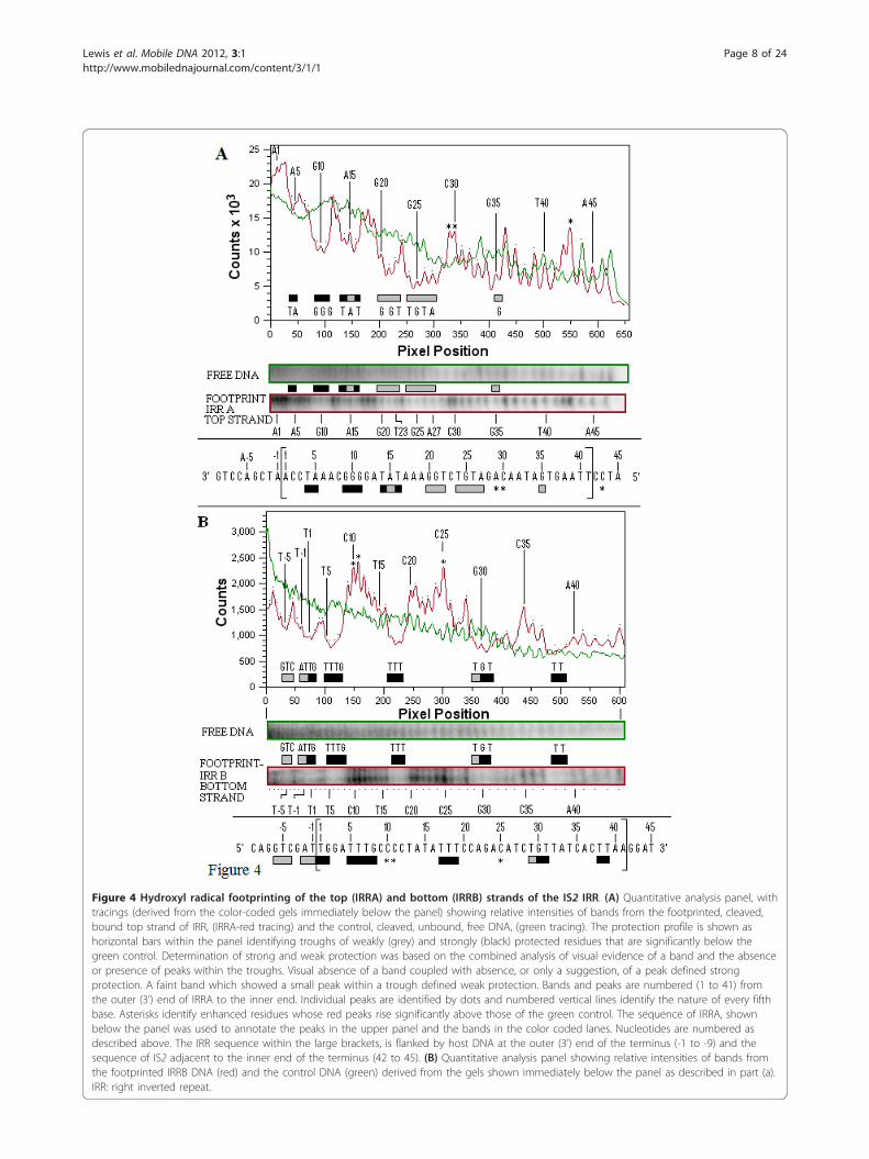
Figure 4 Hydroxyl radical footprinting of the top (IRRA) and bottom (IRRB) strands of the IS2 IRR. (A) Quantitative analysis panel, withtracings (derived from the color-coded gels immediately below the panel) showing relative intensities of bands from the footprinted, cleaved,bound top strand of IRR, (IRRA-red tracing) and the control, cleaved, unbound, free DNA, (green tracing). The protection profile is shown ashorizontal bars within the panel identifying troughs of weakly (grey) and strongly (black) protected residues that are significantly below thegreen control. Determination of strong and weak protection was based on the combined analysis of visual evidence of a band and the absenceor presence of peaks within the troughs. Visual absence of a band coupled with absence, or only a suggestion, of a peak defined strongprotection. A faint band which showed a small peak within a trough defined weak protection. Bands and peaks are numbered (1 to 41) fromthe outer (3’) end of IRRA to the inner end. Individual peaks are identified by dots and numbered vertical lines identify the nature of every fifthbase. Asterisks identify enhanced residues whose red peaks rise significantly above those of the green control. The sequence of IRRA, shownbelow the panel was used to annotate the peaks in the upper panel and the bands in the color coded lanes. Nucleotides are numbered asdescribed above. The IRR sequence within the large brackets, is flanked by host DNA at the outer (3’) end of the terminus (-1 to -9) and thesequence of IS2 adjacent to the inner end of the terminus (42 to 45). (B) Quantitative analysis panel showing relative intensities of bands fromthe footprinted IRRB DNA (red) and the control DNA (green) derived from the gels shown immediately below the panel as described in part (a).IRR: right inverted repeat.
Lewis et al. Mobile DNA 2012, 3:1http://www.mobilednajournal.com/content/3/1/1
Page 8 of 24
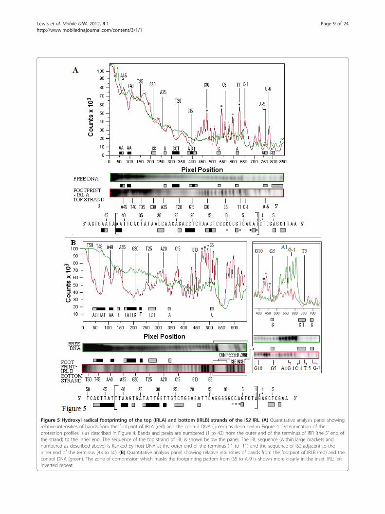
Figure 5 Hydroxyl radical footprinting of the top (IRLA) and bottom (IRLB) strands of the IS2 IRL. (A) Quantitative analysis panel showingrelative intensities of bands from the footprint of IRLA (red) and the control DNA (green) as described in Figure 4. Determination of theprotection profiles is as described in Figure 4. Bands and peaks are numbered (1 to 42) from the outer end of the terminus of IRR (the 5’ end ofthe strand) to the inner end. The sequence of the top strand of IRL is shown below the panel. The IRL sequence (within large brackets andnumbered as described above) is flanked by host DNA at the outer end of the terminus (-1 to -11) and the sequence of IS2 adjacent to theinner end of the terminus (43 to 50). (B) Quantitative analysis panel showing relative intensities of bands from the footprint of IRLB (red) and thecontrol DNA (green). The zone of compression which masks the footprinting pattern from G5 to A-9 is shown more clearly in the inset. IRL: leftinverted repeat.
Lewis et al. Mobile DNA 2012, 3:1http://www.mobilednajournal.com/content/3/1/1
Page 9 of 24
to direct the CD away from a cis interaction with its cog-nate CC by bending the DNA to facilitate binding in transat the active CC, while simultaneously determining theaccuracy of the joining reaction. An additional aspect ofthe data in Figure 6 appears to support this idea. The clea-vage domain of IRL shows a relatively high frequency ofenhanced residues (six of the eleven positions), compared
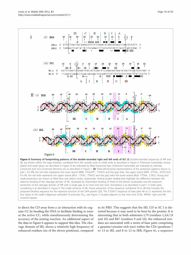
to its PBD. This suggests that the IRL CD in SC I is dis-torted because it may need to be bent by the protein. It isinteresting that in both substrates L79 (residues 1,3,6,7,8and 10) and R87 (residues 9 and 10), the enhanced resi-dues are associated with a series of base pairs comprisinga guanine/cytosine-rich tract within the CDs (positions 7to 13 in IRL and 8 to 12 in IRR; Figure 6), a sequence
Figure 6 Summary of footprinting patterns of the double-stranded right and left ends of IS2. (I) Double-stranded sequences of IRR andIRL are shown within the large brackets, numbered from the outside ends to inside ends as described in Figure 4. Protected nucleotides, strong(black) and weak (grey), (as described in Figure 4) are indicated by filled horizontal bars. Enhanced nucleotides are indicated by asterisks.Conserved and non-conserved elements are as described in Figure 1. (II) Three-dimensional representations of the protection patterns shown inpart I. For IRR, the red helix represents the lower strand (IRRB- 5’TGGATT... TTAA3’) and the gray helix, the upper strand (IRRA- 5’TTAA... AATCCA3’).For IRL the red helix represents the upper strand (IRLA - 5’TAG... TTAA3’) and the grey helix the lower strand (IRLB- 5’TTAA... CTA3’). Strong andweak protections are shown as filled blue and yellow circles, respectively. Vertical purple shaded bars highlight the difference between theselective binding of the cleavage domain of IRL, illustrated by intermittent binding of three of the eleven nucleotides and the extensiveprotection of the cleavage domain of IRR with a single gap at its inner end (see text). Annotation is as described in part I. In both parts,numbering is as described in Figure 4. The inside terminus of IRL shows protection of the sequence numbered 39 to 48 that includes theproposed binding sequence for the repressor function of the OrfA protein [20]. The 5’TGAT3’ sequence of base pairs 48 to 51 represents the firstfour bases of the weak indigenous extended-10 promoter (PIRL, see Figure 1) located adjacent to the inner end of IRL. IRR/IRL: right and leftinverted repeats.
Lewis et al. Mobile DNA 2012, 3:1http://www.mobilednajournal.com/content/3/1/1
Page 10 of 24
which facilitates bending of the DNA [38,39]. In supportof this idea are results from an IS2 derivative with multipletransversion mutations at positions 8 to 12 of IRL (IIRL), inwhich minicircle formation was completely abolished [24],although current results do not show protection of theseresidues by the protein.We interpret these data as suggesting that the IRL CD
is positioned in trans and juxtaposed to the active CCoccupied by the cis-bound IRR CD, in a tract which isprobably that used for non-specific binding to the hostDNA. The importance of non-specific and/or selectivebinding of the adjacent host DNA by the protein receivessupport from our earlier studies, which indicated that thenature of the host DNA flanking the recipient end canplay a role in determining MCJ spacer size [24], as wellas from a more recent report of the binding efficiency ofa truncated version of the IS911 OrfAB (residues 1 to149). This derivative bound much less efficiently to a 36bp substrate containing only the IRR sequence than to alonger 100 bp substrate, due, they proposed, to the non-specific binding capability of the transposase [27]. Thisinterpretation of the architecture of the IS2 SC I isfurther supported by data from studies in which mutatedIS2 derivatives with two left ends produced no minicir-cles [24]. When complexes are formed in vitro with onlyDNA of the left end, several factors would then workagainst either IRL functioning as a donor (that is, boundin cis at its cognate CC): selective rather than extensivebinding of their CDs; the non-specific and/or selectivebinding of adjacent host DNA; their longer length (onebp) than donor IRRs; the reduced affinity of the TPasefor the adjacent BIRL element; and the tendency of theCDs to be bent by the protein. These factors would pre-vent minicircle formation and therefore define the iden-tity of the recipient end in the wild type element.In elements with two right ends, however, both func-
tion as donors with equal probability and produce mini-circles in which approximately 90% of the MCJs haveinterstitial sequences of 2 bp to 3 bp. This would not bethe case if both donor CDs were complexed in cis attheir cognate CCs (Figure 2A) when the majority ofminicircles would have 5 bp interstitial sequences. Incomplexes formed with two right ends, the CD of oneend is bound in cis and that of the other bound intrans, both at a single active CC. Binding in trans wouldbe facilitated by the non-specific and/or selective bind-ing of the adjacent host DNA coupled with the bendingof the CD by the protein as indicated by enhancementsat residues 9 and 10.Different conformational states define the protein-DNA
interactions of IRR and IRL not only at their outside endsbut also at their inside ends, primarily due to the differentfunctions of the ends. At the inside ends of IRR and IRL,different protection patterns involve the two most distal
elements (C and III) of the PBD (Figure 6). The strongerprotection pattern in elements CIRL and IIIIRL is a manifes-tation of the location of the docking site, 5’TAAATAA3’,for the repressor function of OrfA, (Figure 1C, ii; [20,40]).The transposase bound to IRL (Figure 5) shows strongprotection of the last 4 bp at the inside end of IRL, T/A,T/A, A/T, A/T (residues 39 to 42 of element III), and the6 bp sequence A/T, T/A, A/T, A/T, G/C, T/A (residues43 to 48) located immediately adjacent to the inside endand just upstream of PIRL, the extended-10 promoter [10].These two sequences together appear to form a 10 bpsequence which includes the site to which the 14 kDaOrfA binds competitively in carrying out its repressorfunction. It is interesting that the truncated 17 kDa deriva-tive of the IS30 TPase (the structural equivalent of OrfA)has also been shown to overlap the promoter region, likelyrepressing transcription [37], but that OrfA in IS911 doesnot have this function. Instead, it has been shown to mod-ify the stoichiometry of complexes formed with the 1-149truncated forms of OrfAB [26]. In addition, in IS911 OrfAis involved with both heteromultimerization with OrfAB[41], as well as with its own homomultimerization andwith the ability to stimulate minicircle insertion in vitrointo target DNA not associated with the IS911 ends [28].It is likely that these heteromultimers may also exist inour preparations, which consist of a mixture of OrfA andOrfAB [31]. Speculatively, in IS2, the three-dimensionalconfiguration of OrfAB could allow the BD of the proteinto target the B and II elements in the PBD, whereas (as aregulatory mechanism) the BD in OrfA, with a slightly dif-ferent configuration, would target the promoter.Three previous studies have reported footprinting ana-
lyses of the IS3 family and related elements that hint atthe bipartite nature of the ends. Earlier, Hu et al. [23],using cell-free extracts of the IS2 Tpase, reported in situ1, 10 phenanthroline-copper ion footprinting data for thebottom strand of the right end (5’-TGG... TTAA-3’) andthe top strand of the left end (5’-TAG.... TTAA-3’) ofIS2. They showed essentially identical patterns of protec-tion of residues 16 to 41 in the case of IRR and 16 to 42in the case of IRL with additional protection of residue43 in the former and protection of residues 43 to 46 inthe latter. They reported no binding to the outer basepairs, 1 to 15, for either end, due perhaps to the preva-lence of truncated N-terminal species in the preparationof the protein [26] or to the imprecise folding of the C-terminus, a process which appears to have been avoidedin our GFP-tagged version [31].Normand et al. [26] reported DNase I and Cu(OP)2
(copper-1,10phenanthroline) footprinting data for IRRand IRL single-ends of IS911 using a truncated versionof OrfAB (residues 1 to 149) from which the carboxy-terminus was deleted; the protein thus consisted primar-ily of its binding and dimerization domains. Their
Lewis et al. Mobile DNA 2012, 3:1http://www.mobilednajournal.com/content/3/1/1
Page 11 of 24
deletion-gel retardation analyses of the ends of IS911showed that they are composed of three conservedblocks of residues a, b and g; b and g comprise the PBDof IRR and IRL whereas the a motif comprises the CD.Footprinting experiments with both IRR and IRLshowed that the truncated OrfAB bound efficiently inan extensive manner to the PBDs of the ends. Finally,DNase I footprinting experiments with the 17 kDa N-terminal derivative of the IS30 Tpase containing onlythe BD of the protein, showed binding to the centralregion of an inner, presumed PBD, leaving the outer ter-mini of both right and left ends unprotected [37].The bipartite nature of the ends of transposable ele-
ments has been well documented by mutational analysisand DNA footprinting studies. The two domains, origin-ally identified through mutational studies in IS903 [42],IS50 (Tn5) [43,44] and IS10 [45], were subsequentlyshown in early DNA footprinting studies to be a uniqueinner binding sequence for the transposase and an outerunbound sequence assigned to post binding cleavagefunctions. This was shown to be true for simple insertionsequences IS30 [37], IS1 [46], IS903 [47], IS50 [48] andIS911 [26] as well as for the more complex transposons,Tn3 [49-51] and Mu [52,53]. Binding to both domains,however, was shown to occur in fully formed SCs in Mu[54-56] and in IS50 [36]. We conclude from these ana-lyses that the bipartite binding pattern exhibited in IS2protein/DNA complexes is the result of a fully formedStep I SC.
Footprinting results in SC I correlate well with those ofprevious mutational analyses of the PBD of the singleIRL endAn earlier mutational analysis of the IRL sequence indi-cated that, while residues 12 to 19 (primarily the B ele-ment) played an important role in protein recognition, ananchoring sequence for the transposase was also located atresidues 20 to 42 (elements II, C and III; [24]). In general,the footprinting data (Figure 6) support these conclusions.We assessed the effect of seven single base deletion muta-tions on the efficiency of minicircle formation and foundthat there is a good correlation with current binding effi-ciency data. Deletion of base pairs at positions 13, 19, 21and 36 had no effect on minicircle efficiency. In these foot-printing studies, only position 21 was protected by theprotein. Deletions of base pairs at positions 14, 26 and 29eliminated minicircle formation and only residue 26 wasnot protected by the protein.
Footprinting the IS2 MCJIn Step II of the IS2 transposition pathway, donor func-tion of each of the abutted ends at the MCJ is a prere-quisite for insertion of the element into the targetsequence. In an earlier model [10,24], we proposed for
the sake of simplicity that the complex involved a dimerof transposase molecules with the PBD of each endbound at its own monomer. Initial cleavage of theabutted CDs of the MCJ would occur at the 3’ end ofthe IRR CD, bound in cis at its cognate CC (a first tran-sition state). As a result of a conformational change thepartially cleaved junction would be relocated to permitcis-binding of the IRL CD at its cognate CC (a secondtransition state). There, cleavage at its 3’ terminuswould occur, permitting the reacquisition of cis bindingby the IRR CD.To test these ideas, we asked here whether a covalently
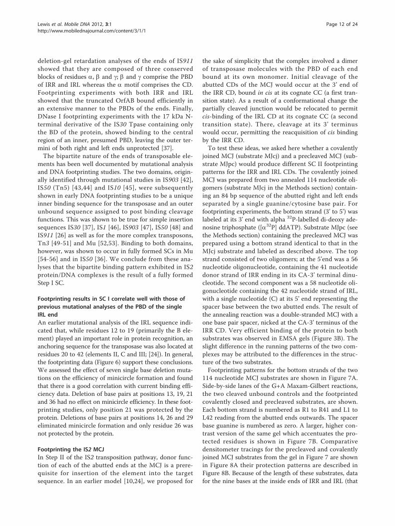
joined MCJ (substrate MJcj) and a precleaved MCJ (sub-strate MJpc) would produce different SC II footprintingpatterns for the IRR and IRL CDs. The covalently joinedMCJ was prepared from two annealed 114 nucleotide oli-gomers (substrate MJcj in the Methods section) contain-ing an 84 bp sequence of the abutted right and left endsseparated by a single guanine/cytosine base pair. Forfootprinting experiments, the bottom strand (3’ to 5’) waslabeled at its 3’ end with alpha 32P-labelled di-deoxy ade-nosine triphosphate ([a32P] ddATP). Substrate MJpc (seethe Methods section) containing the precleaved MCJ wasprepared using a bottom strand identical to that in theMJcj substrate and labeled as described above. The topstrand consisted of two oligomers; at the 5’end was a 56nucleotide oligonucleotide, containing the 41 nucleotidedonor strand of IRR ending in its CA-3’ terminal dinu-cleotide. The second component was a 58 nucleotide oli-gonucleotide containing the 42 nucleotide strand of IRL,with a single nucleotide (C) at its 5’ end representing thespacer base between the two abutted ends. The result ofthe annealing reaction was a double-stranded MCJ with aone base pair spacer, nicked at the CA-3’ terminus of theIRR CD. Very efficient binding of the protein to bothsubstrates was observed in EMSA gels (Figure 3B). Theslight difference in the running patterns of the two com-plexes may be attributed to the differences in the struc-ture of the two substrates.Footprinting patterns for the bottom strands of the two
114 nucleotide MCJ substrates are shown in Figure 7A.Side-by-side lanes of the G+A Maxam-Gilbert reactions,the two cleaved unbound controls and the footprintedcovalently closed and precleaved substrates, are shown.Each bottom strand is numbered as R1 to R41 and L1 toL42 reading from the abutted ends outwards. The spacerbase guanine is numbered as zero. A larger, higher con-trast version of the same gel which accentuates the pro-tected residues is shown in Figure 7B. Comparativedensitometer tracings for the precleaved and covalentlyjoined MCJ substrates from the gel in Figure 7 are shownin Figure 8A their protection patterns are described inFigure 8B. Because of the length of these substrates, datafor the nine bases at the inside ends of IRR and IRL (that
Lewis et al. Mobile DNA 2012, 3:1http://www.mobilednajournal.com/content/3/1/1
Page 12 of 24
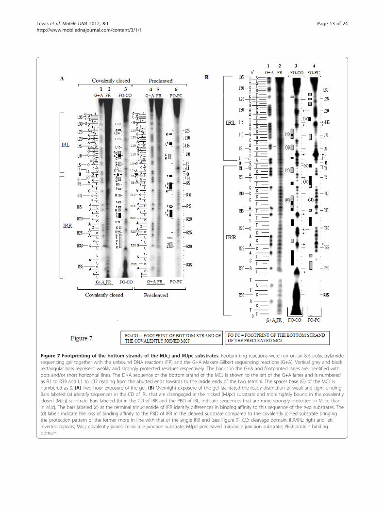
Figure 7 Footprinting of the bottom strands of the MJcj and MJpc substrates. Footprinting reactions were run on an 8% polyacrylamidesequencing gel together with the unbound DNA reactions (FR) and the G+A Maxam-Gilbert sequencing reactions (G+A). Vertical grey and blackrectangular bars represent weakly and strongly protected residues respectively. The bands in the G+A and footprinted lanes are identified withdots and/or short horizontal lines. The DNA sequence of the bottom strand of the MCJ is shown to the left of the G+A lanes and is numberedas R1 to R39 and L1 to L37 reading from the abutted ends towards to the inside ends of the two termini. The spacer base (G) of the MCJ isnumbered as 0. (A) Two hour exposure of the gel. (B) Overnight exposure of the gel facilitated the ready distinction of weak and tight binding.Bars labeled (a) identify sequences in the CD of IRL that are disengaged in the nicked (MJpc) substrate and more tightly bound in the covalentlyclosed (MJcj) substrate. Bars labeled (b) in the CD of IRR and the PBD of IRL, indicate sequences that are more strongly protected in MJpc thanin MJcj. The bars labeled (c) at the terminal trinucleotide of IRR identify differences in binding affinity to this sequence of the two substrates. The(d) labels indicate the loss of binding affinity to the PBD of IRR in the cleaved substrate compared to the covalently joined substrate bringingthe protection pattern of the former more in line with that of the single IRR end (see Figure 9). CD: cleavage domain; IRR/IRL: right and leftinverted repeats; MJcj: covalently joined minicircle junction substrate; MJpc: precleaved minicircle junction substrate; PBD: protein bindingdomain.
Lewis et al. Mobile DNA 2012, 3:1http://www.mobilednajournal.com/content/3/1/1
Page 13 of 24
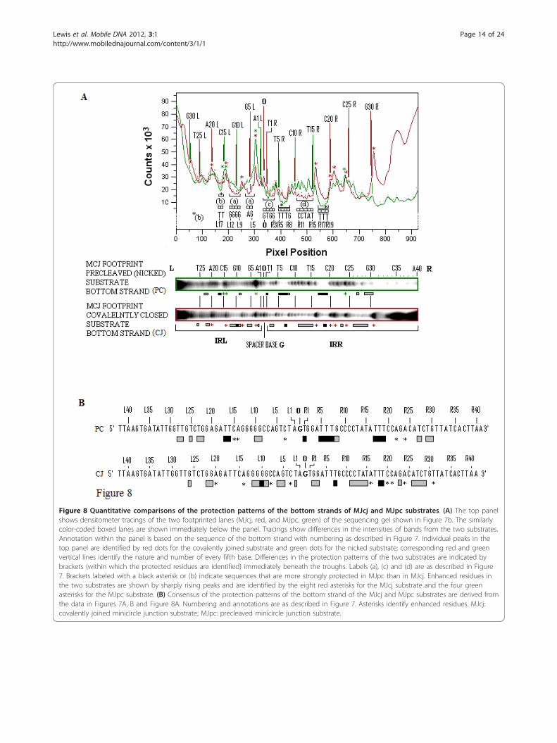
Figure 8 Quantitative comparisons of the protection patterns of the bottom strands of MJcj and MJpc substrates. (A) The top panelshows densitometer tracings of the two footprinted lanes (MJcj, red, and MJpc, green) of the sequencing gel shown in Figure 7b. The similarlycolor-coded boxed lanes are shown immediately below the panel. Tracings show differences in the intensities of bands from the two substrates.Annotation within the panel is based on the sequence of the bottom strand with numbering as described in Figure 7. Individual peaks in thetop panel are identified by red dots for the covalently joined substrate and green dots for the nicked substrate; corresponding red and greenvertical lines identify the nature and number of every fifth base. Differences in the protection patterns of the two substrates are indicated bybrackets (within which the protected residues are identified) immediately beneath the troughs. Labels (a), (c) and (d) are as described in Figure7. Brackets labeled with a black asterisk or (b) indicate sequences that are more strongly protected in MJpc than in MJcj. Enhanced residues inthe two substrates are shown by sharply rising peaks and are identified by the eight red asterisks for the MJcj substrate and the four greenasterisks for the MJpc substrate. (B) Consensus of the protection patterns of the bottom strand of the MJcj and MJpc substrates are derived fromthe data in Figures 7A, B and Figure 8A. Numbering and annotations are as described in Figure 7. Asterisks identify enhanced residues. MJcj:covalently joined minicircle junction substrate; MJpc: precleaved minicircle junction substrate.
Lewis et al. Mobile DNA 2012, 3:1http://www.mobilednajournal.com/content/3/1/1
Page 14 of 24
is, resides 33 to 42) were difficult to ascertain and areexcluded from this analysis.
CDs in the MJcj substrate are complexed to the samecatalytic center followed by a cleavage-triggeredconformational changeSeveral features help compare and contrast the protec-tion patterns of the covalently joined and precleavedsubstrates. We can also contrast these with the protec-tion patterns of the single-end substrates. Comparativeschematic representations of the protection patterns ofthe bottom strands of the four substrates, that is, thetwo single-end substrates and the two MCJ substrates,are shown in Figure 9. First, some residues within twoshort sequences (R1 to 3 and 5 to 8) in the bottomstrand of the IRR CD are protected in all three sub-strates (compare residues R1 to R8 in Figure 9). Thesimilarity of protection patterns is particularly true forthe MJpc and single-end substrates. The lower affinityfor the residues in the MJcj IRR CD may be a conse-quence of the need to accommodate binding and clea-vage of the IRL CD post-IRR cleavage at the same activeCC, implying that cleavages are sequential and that thecleavage of IRL occurs in trans. We thus conclude thatthe IRR CD is bound in cis at its cognate CC in allthree substrates (Figure 10A, B).Secondly, in the MJcj substrate, the CDs of both IRL
and IRR are protected in a similar manner by the protein(compare L2, L5, L6 and L9 to 11 with R2, R3, R7 andR11 in Figure 9 and 7B, lane 3). This result suggests thatthe CD of IRL in the MJcj substrate is extensively bound
at the same CC as the IRR CD. Since the two CDs in theIS2 MJcj substrate are separated by a single base pair,their observed extensive protection (summarized inFigure 9) should result from initial binding of both CDs(the IRL in trans and the IRR in cis) at a single active CC(Figure 10B). This represents the first phase of the SC IIcomplex in IS2. A similar scenario may apply to IS21[29], IS1665 [30] and IS256 in Tn4001 [28].Thirdly, the MJpc substrate shows evidence of disen-
gagement of the IRL CD from the TPase (Figure 9). Inthe covalently joined substrate, three sets of residueswithin the IRL CD are bound moderately tightly (L2(T), L5 and L6 (GA) and L9 to L12 (GGGG)); of these,only two residues (L9 and L10) are protected in the pre-cleaved substrate (see also the protection patternslabeled (a) in Figures 7B and 8A). This is not the casefor the IRR CD where binding is even more extensivethan in the MJcj. Based on two lines of evidence, weconclude that the partially cleaved junction is not posi-tioned at the IRL CC after right end cleavage, as sug-gested in our original hypothesis. First, the apparentdisengagement of the IRL CD suggests that it is notbound extensively at its cognate CC. Secondly, the IRRCD in the precleaved substrate remains bound at itscognate CC as judged by the similarity of its protectionpattern to that of the single-end substrate. We proposethen, that the protection patterns observed for the MJpcsubstrate represent those of a temporary (and artifac-tual) transition state and that complete disengagementof the IRL CD would follow the two sequential single-strand cleavages at the IRR CC (Figure 10B). After a
Figure 9 Comparisons of protection patterns of the bottom strands of the single-end, MJcj and MJpc substrates. The sequence shownis that of the bottom strand of the MCJ with the spacer base guanine separating the abutted right and left ends. Numbering of the bases is asdescribed in Figure 7. Protection patterns are indicated by horizontal bars. Asterisks identify enhanced residues. Three stacked asterisks describeincreased enhancement. Broken vertical lines within the large brackets demarcate the IRR and IRL cleavage domains (CD) and protein bindingdomains (PBD). Data for residues L30 to L42 and R32 to R41 of the MCJ substrates were difficult to interpret and are not shown. CD: cleavagedomain; IRR/IRL: right and left inverted repeats; MCJ: minicircle junction; MJcj: covalently joined minicircle junction substrate; MJpc: precleavedminicircle junction substrate; PBD: protein binding domain.
Lewis et al. Mobile DNA 2012, 3:1http://www.mobilednajournal.com/content/3/1/1
Page 15 of 24
conformational change, re-engagement of the IRL CD ata new site, its cognate CC, would then occur to producea second complex in SC II (Figure 10C).There is additional evidence for this temporary transi-
tion state. Two differences within the CDs of the two MCJsubstrates at residues R1 (T) and R5 to R8 (TTTC) makethe profile of the IRR CD in the MJpc substrate almostidentical to that of the single-end substrate (Figure 9; seealso the gel in Figure 7B, lane 4, protection patternslabeled (b) and (c)). Also, there are subtle differences inthe protection patterns of the IRR PBD in the two MCJsubstrates; residues R11 to R15, which are protected in theMJcj substrate, are disengaged in the MJpc substrate (Fig-ure 7B, compare lanes 3 and 4, protection patterns labeled(d)), again making its protection pattern almost entirelylike that of the single-end substrate (Figure 9). We note
that major changes in protection patterns do not affect thePBDs. There is a basic similarity but not identity in theprotection patterns within the PBDs IRR (R17 to R19 andR26 to R31) and IRL (L15 to L18 and L21 to L28) in eachof the three substrates (Figure 9).It is now well understood that the process of transposi-
tional recombination is controlled by a series of confor-mational changes within the transpososome that drivethe process forward unidirectionally. These may be trig-gered by cleavages [57], host proteins [58], divalentcations [59], the role of terminal cognate nucleotides [60]and associated transposition proteins [61]. It appearshere that sequential cleavages at the abutted IRR and IRLCDs of the first phase in the SC II transpososome of IS2would provoke the conformational change that isrequired for the establishment of the second phase that is
*
*
IRR
ActiveIRRC
IRLC
IRL(A) (B) (C)
SC I SC II
BS
BS
*
*
*
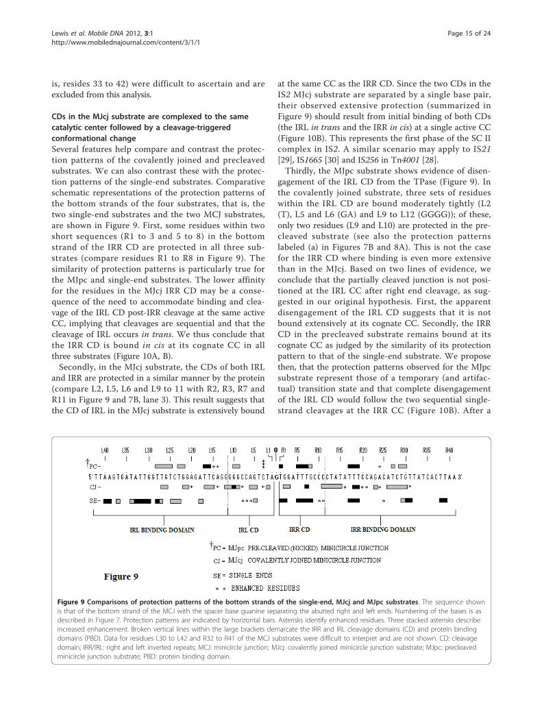
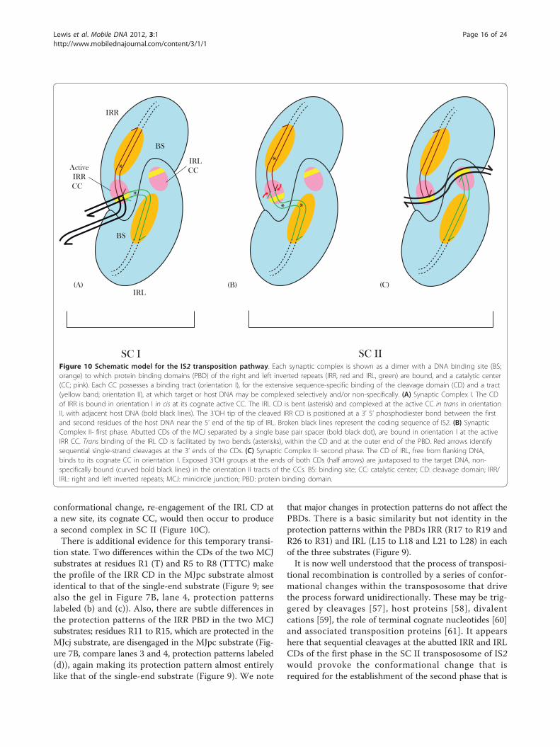
Figure 10 Schematic model for the IS2 transposition pathway. Each synaptic complex is shown as a dimer with a DNA binding site (BS;orange) to which protein binding domains (PBD) of the right and left inverted repeats (IRR, red and IRL, green) are bound, and a catalytic center(CC; pink). Each CC possesses a binding tract (orientation I), for the extensive sequence-specific binding of the cleavage domain (CD) and a tract(yellow band; orientation II), at which target or host DNA may be complexed selectively and/or non-specifically. (A) Synaptic Complex I. The CDof IRR is bound in orientation I in cis at its cognate active CC. The IRL CD is bent (asterisk) and complexed at the active CC in trans in orientationII, with adjacent host DNA (bold black lines). The 3’OH tip of the cleaved IRR CD is positioned at a 3’ 5’ phosphodiester bond between the firstand second residues of the host DNA near the 5’ end of the tip of IRL. Broken black lines represent the coding sequence of IS2. (B) SynapticComplex II- first phase. Abutted CDs of the MCJ separated by a single base pair spacer (bold black dot), are bound in orientation I at the activeIRR CC. Trans binding of the IRL CD is facilitated by two bends (asterisks), within the CD and at the outer end of the PBD. Red arrows identifysequential single-strand cleavages at the 3’ ends of the CDs. (C) Synaptic Complex II- second phase. The CD of IRL, free from flanking DNA,binds to its cognate CC in orientation I. Exposed 3’OH groups at the ends of both CDs (half arrows) are juxtaposed to the target DNA, non-specifically bound (curved bold black lines) in the orientation II tracts of the CCs. BS: binding site; CC: catalytic center; CD: cleavage domain; IRR/IRL: right and left inverted repeats; MCJ: minicircle junction; PBD: protein binding domain.
Lewis et al. Mobile DNA 2012, 3:1http://www.mobilednajournal.com/content/3/1/1
Page 16 of 24
needed for final strand transfer reactions into the targetDNA.
The sequence of the IRL CD has evolved to permitselective binding in SC I without compromising extensivesequence-specific binding in SC IIIn earlier studies we proposed that the non-conservedbase pairs in IRL were necessary for efficient recipientend function and were sufficient to prevent binding ofthe CD in cis to its cognate active site in SC I, withoutcompromising binding proficiency in SC II [24]. Foot-printing data for the MJcj substrate support these sup-positions. Six of the eleven residues within IRL CD inthe bottom strand of the MJcj substrate are bound bythe protein. The non-conserved residues at positions L2and L5 are protected, as is the run of guanines at posi-tions L9 (non-conserved) to L12 (Figure 9). Protectionof this guanine/cytosine run is characteristic of strongextensive binding in the single-end IRR substrate and isnot observed in the single-end IRL substrate (Figure 6).Thus, two of the three residues in the IRL CD that areinvolved in selective binding in SC I, are also utilized inextensive sequence-specific binding in SC II. It seemslikely that this extensive sequence-specific binding of theIRL CD in the MJcj substrate results partially from itsproximity to the extensively bound IRR CD. In addition,given the proximity of selective binding of the IRL CD andthe non-specific and/or selective binding of the adjacenthost DNA in the L79 single-end substrate (Figure 6), wepropose that the nature of (or the absence of) the DNAadjacent to the cleavage domain of IRL plays a decisiverole in determining whether it is involved in selectivebinding or extensive sequence-specific binding.
Evidence for bending of the DNA in MCJ and single-endsubstrates from footprinting data is corroborated bycurvature propensity plot data from the MJcj sequenceThe differences in the protection patterns of the MJcjand MJpc may be due to perturbation, generated as sug-gested above by the binding of both CDs at a single activesite. Perturbation in the MJcj substrate is indicated by thepresence of five enhanced residues in the PBD of IRR andfour enhanced residues in the CD and the PBD of IRL. Incontrast, in the MJpc substrate, only a single residue(R24) is enhanced in the PBD of IRR (Figure 9; see alsoFigure 7B, lanes 3 and 4 and Figure 8), suggesting notonly that perturbation of the IRR DNA is relieved follow-ing cleavage but that the remaining enhanced R24 resi-due in both substrates is indicative of intrinsic bending atthat site. In addition, the location of the enhanced regionwithin the PBD of the IRR single end substrate (see resi-dues R25 and R29 to R30; Figure 6) is similar to that inthe two MCJ substrates (see residue R24; Figure 9), sug-gesting a single bend in IRR DNA in all three substrates.
In a similar vein, enhanced residues in IRL are observedat two identical locations in the MJcj and MJpc sub-strates, that is, residue L3 in the CD and L14 at the outerend of the PBD (Figures 8 and 9). An enhanced residue isalso observed at L15 in MJpc. In addition the enhancedregion in the CD of the IRL single-end substrate (seeresidues L1, L3, L6 to L8 and L10; Figure 6) is in thesame location in the MCJ substrates (see residues L3 andL8; Figure 9), suggesting that the tip of IRL is bent in allthree substrates to accommodate binding in trans to itsCD at the active IRR CC as illustrated in Figure 10A, B.Thus the presence of enhanced residues that are at com-mon or near common locations in the single end, MJcjand MJpc substrates may be indicative of bending atintrinsically bent sites (see below).The observation that these sequences, which are con-
sistently bent at approximately the same positions in SC Iand SC II, occur at regions associated with guanine/cyto-sine-rich tracts in the CDs prompted us to evaluate theirintrinsic curvature (that is, the permanent or time-aver-aged deflexion of the DNA axis when no external force isapplied) by analyzing the abutted terminal repeats of IS2with the bend.it server (see Methods). The purpose ofusing this tool was to evaluate whether regions are inher-ently curved during the interactions between CDs withinthe SC II complex. According to the curvature propensityplot obtained (Figure 11A (i)), three strong maxima areevident in the IRR and IRL regions of the MJcj sequence:two in the PBDs (R25, L25) and one in the IRL CD (L6).In addition, a weak maximum is observed in the IRRcleavage domain at R9. With the exception of L25 in theIRL PBD, the remaining positions match or are locatedclose to the enhanced residues in the footprinting gels(compare with Figure 9) but the position of L25 stillappears to be related to the enhancement data in theMCJ substrates, in that both sets of data suggest thatthere is a bend at the outer half of the PBD of IRL. Afifth maximum is also present at L60 which correspondsto the location of the indigenous PIRL promoter. This isexpected, for promoter sequences are well known to becharacterized by intrinsically curved DNA [62,63]. Tobetter understand exactly how this curvature profiletranslates in terms of DNA architecture, we generated athree-dimensional representation (Figure 11A (ii)) usingthe same MCJ DNA and obtained an S-like structurewhich is typical of some regional anisotropic flexibility.As stated above, this seems to result from an overrepre-sentation of guanine/cytosine-rich tracts in the CDs,which, in conjunction with other properly phasedsequences, results in a preferential curvature.We have asked whether the curvature maxima identi-
fied within the MJcj sequence are a reflection of theintrinsic curvature resulting from the interaction of thetwo CDs or curvature associated with the powerful
Lewis et al. Mobile DNA 2012, 3:1http://www.mobilednajournal.com/content/3/1/1
Page 17 of 24
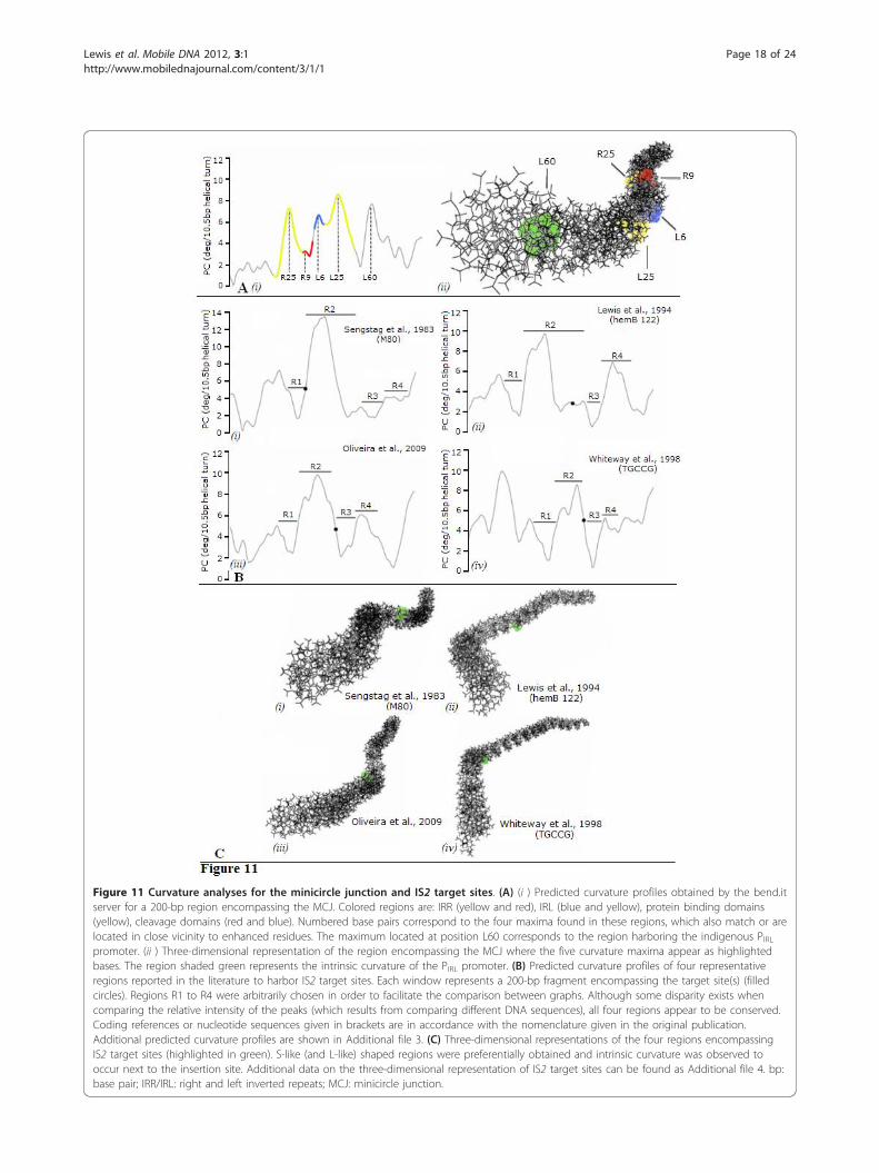
Figure 11 Curvature analyses for the minicircle junction and IS2 target sites. (A) (i ) Predicted curvature profiles obtained by the bend.itserver for a 200-bp region encompassing the MCJ. Colored regions are: IRR (yellow and red), IRL (blue and yellow), protein binding domains(yellow), cleavage domains (red and blue). Numbered base pairs correspond to the four maxima found in these regions, which also match or arelocated in close vicinity to enhanced residues. The maximum located at position L60 corresponds to the region harboring the indigenous PIRLpromoter. (ii ) Three-dimensional representation of the region encompassing the MCJ where the five curvature maxima appear as highlightedbases. The region shaded green represents the intrinsic curvature of the PIRL promoter. (B) Predicted curvature profiles of four representativeregions reported in the literature to harbor IS2 target sites. Each window represents a 200-bp fragment encompassing the target site(s) (filledcircles). Regions R1 to R4 were arbitrarily chosen in order to facilitate the comparison between graphs. Although some disparity exists whencomparing the relative intensity of the peaks (which results from comparing different DNA sequences), all four regions appear to be conserved.Coding references or nucleotide sequences given in brackets are in accordance with the nomenclature given in the original publication.Additional predicted curvature profiles are shown in Additional file 3. (C) Three-dimensional representations of the four regions encompassingIS2 target sites (highlighted in green). S-like (and L-like) shaped regions were preferentially obtained and intrinsic curvature was observed tooccur next to the insertion site. Additional data on the three-dimensional representation of IS2 target sites can be found as Additional file 4. bp:base pair; IRR/IRL: right and left inverted repeats; MCJ: minicircle junction.
Lewis et al. Mobile DNA 2012, 3:1http://www.mobilednajournal.com/content/3/1/1
Page 18 of 24
promoter within the MCJ sequence. Since the curvaturemaxima at L6 and R25 correspond to enhancements inboth the single-end substrates and the MCJ substratesas described above, we interpret the enhancements inthe L79 (IRL) substrate as the result of bending toaccommodate binding of both IRL CDs in trans in SC I(see the bend in IRL in Figure 10A) and in the MJcjsubstrate as bending to accommodate binding of theabutted CDs of the MCJ to a single CC in SC II (Figure10B); indeed, observed perturbations of the DNA in thefootprinted gels of the MJcj and MJpc substrates or ofthe single ends may result from the DNA being bent bythe protein in the same direction as the intrinsicsequence-dependent curvature [64]. We note that thereis no enhancement of the residues in the PBD of theL79 (IRL) single-end substrate corresponding to the L25maximum of the MCJ sequence (see below). In addition,the weak curvature maximum at R9 in the MJcjsequence is probably a relic of the type of IRR CD toCD interaction described earlier, for elements with tworight ends. Thus the intrinsic curvature data not onlycorroborate the footprinting data but also support theidea that interaction of the CDs at a single active CCrequires the adoption of a bent structure.
Intrinsic curvature of IS2 target sitesBecause binding of the IRL CD in trans at the active CCwithin SC I and SC II seems to require the DNA to adopta bent structure, we wondered whether IS2 target sitescould also be structurally constrained. Therefore wedecided to look at the predicted curvature of 200 bp-sized sequences from several IS2 target sites reported inthe literature. A representative sample of these is shownin Figure 11B (the remaining curvature profiles are pre-sented in Additional file 3). An interesting feature of thedata is a consistent periodic behavior of the predictedcurvature of sequences flanking the target sites. Subse-quent analysis led to the division of the target sites intofour regions (R1 to R4), a profile which was roughly simi-lar in all of the DNA sequences examined. R1 holds alocal minimum in predicted curvature, R2 a local maxi-mum harboring a shoulder peak that sometimes appearsas two well resolved peaks and regions, and R3 and R4hold a local minimum and maximum respectively. IS2insertion sites (black dots) mapped preferentially withinthe sub-sequences of R2 with a mean curvature of 4.4 ±1.9 degrees per 10.5 bp helical turn. It is thus tempting toassume that the choice of insertion site might depend onDNA curvature at the target with the decision for inte-gration based on subsequences of R2 having a certainrange of curvature values. This similarity between curva-ture profiles is reflected in the three-dimensional struc-ture of each region (Figure 11C) where an S-like (andsometimes L-like) structure is preferentially adopted. IS2
insertion sites were found to be located between twobent regions ([65,66]; Figure 11C, i, ii) or alternativelyexactly at a bent region ([67,68]; Figure 11C, iii, iv). Addi-tional three-dimensional representations of the curvatureprofiles are also presented in Additional file 4.
A model for the two-step transposition pathway of IS2;CD to CD interactions require that IRL adopt a bentstructure in SC I and SC IIWe describe here a refined version of our model for SCI and SC II [24]. For SC I, single bends of the IRR PBDand of the IRL CD are required to synapse the CDs intwo different orientations, I and II respectively, at thesingle active CC as illustrated in Figure 10A. For thefirst phase of the SC II complex, binding of the twoCDs separated by a single base pair suggest that theCDs are complexed in orientation I at the active IRRCC. Two bends of IRL, at the CD and the outer end ofthe PBD and a single bend of the IRR PBD are neededto achieve this binding arrangement (Figure 10B), wheresequential cleavage reactions would occur to generatethe second phase of the complex (Figure 10C).Intrinsic curvature data have indicated that both MCJ
DNA and target sites adopt bent structures that apparentlyshare identical profiles (compare Figure 11A (i) and 11B).Given the large number of target sites analyzed (Addi-tional file 4), it is tempting to assume that curving propen-sity might play some role in target site selection althoughit is not clear how and to what extent this would affect themechanics of transposition. A similar dependence betweentransposition and target curvature has been shown to existfor IS231 [38], where target sites contain alternate gua-nine/cytosine- and adenine/thymine-rich tracts that pro-mote bending in opposite directions of the regionsflanking the consensus target sequence. In a more recentexample, Kobori et al. [69] reported a target site for thespontaneous insertion of IS10 located within an intrinsi-cally bent DNA region of the commonly used vectorpUC19. Likewise, we observe from Figure 11C that IS2preferentially inserts in the close vicinity of curved regionsor specifically at a bent region. This concept has beenincorporated into the model of the second phase of the SCII complex, where curved target DNA is now bound non-specifically across each CC permitting strand transfer tothe target by each donor end (Figure 10C).
MethodsBacterial strains and mediaEscherichia coli strain JM105 was used for cloning andfor most procedures involving plasmid DNA prepara-tion. DNA transformation was carried out into super-competent XL1 Blue cells (Stratagene Inc., Santa Clara,CA, USA) for reactions requiring cloning and expression
Lewis et al. Mobile DNA 2012, 3:1http://www.mobilednajournal.com/content/3/1/1
Page 19 of 24
of pLL2522, the plasmid with the fused orfAB andGFPuv genes.Cultures were routinely grown in lysogeny broth
media at 37°C, supplemented where necessary with car-benicillin (Cb, 50 μg/mL) or chloramphenicol (Cm, 20μg/mL). For the overexpression of the fused orfAB::GFPgenes in plasmid pLL2522, cultures were grown at 28°Cin a 2× yeast extract and tryptone (2 × YT) mediumsupplemented with Cm, Cb and arabinose (6 mg/mL).
DNA proceduresDNA procedures were essentially as described earlier[10,11,24].
Plasmid constructspLL2522, which contained the fused orfAB and GFPuvgenes, has been described in detail previously [31].
Preparation of the OrfAB-GFP fusion protein under nativeconditionsPlasmid pLL2522 was transformed into BL21(DE3)pLysScells (Stratagene Inc.). Single colonies were inoculatedinto 40.0 mL of 2 × YT medium supplemented with Cm,Cb and arabinose and inoculated in baffled flasks over-night at 28°C. Harvested pellets were checked for brightfluorescence, washed with 3.0 mL Native Wash Buffer(Qiagen, Valencia, CA, USA) and frozen at -70°C for15 min. Three milliliters of B-PER Protein ExtractionReagent (Thermo Scientific, Pierce Protein Research Pro-ducts, Rockford, IL, USA), supplemented with 4.0 μL ofBenzonase (Novagen-EMD4Biosciences, La Jolla, CA,USA), per 40 mL of overexpressed culture and 3.0 mLProtease Arrest (Calbiochem/EMD La Jolla, CA, USA)per milliliter of lysate was added to the frozen pellet,which was allowed to thaw on ice on a horizontal rotaryshaker for 60 min. The lysate was nutated at 4°C for 1 hand subjected to a hard spin at 10,000 ×g for 45 min at4°C. It was then purified through Ni-NTA His-tag tech-nology. 6 × His-tag purification of the protein wasachieved by gravity flow affinity chromatography usingNi-NTA agarose (Qiagen) under native conditions essen-tially following the manufacturer’s instructions. Thecrude lysate was loaded on to a 1.0 mL bed of the nickel-charged resin in a 5.0 mL column for chromatographicseparation followed with UV light. The protein bound asa tight brightly fluorescing band at the top of the columnand remained bound through washings with 10 mM to60 mM imidazole, when a slight dissociation of the bandwas observed. To circumvent continued dissociation, theband was eluted with 250 mM imidazole and its progressthrough the column followed. Peak fractions (fluorome-trically determined) were subjected to diagnostic 12%PAGE using acrylamide and bis-acrylamide (Ac:Bis;30%:8%, respectively) polyacrylamide gels [31]. Fractions
showing both the 74-kDa OrfAB::GFP and the 17-kDaOrfA proteins were pooled (approximately 700 μL), con-centrated to about 75 μL in a YM-10 Microcon Centrifu-gal Filter Device (Millipore, Billerica, MA, USA), dialyzedovernight in Slide-A-Lyzer cassettes (Thermo Scientific,Pierce Protein Research Products) and stored in 50% gly-cerol at -20°C. The concentration of the fused OrfAB-GFP protein was measured with spectrophotometry at397 nm and that of the control GFP at 280 nm and 397nm. Comparative levels of fluorescence of GFP and thefusion proteins were measured with fluorometry andused to confirm the concentration data.
Oligonucleotides used in gel retardation and DNAfootprinting experimentsThe right single end (IRR) was represented by an 87-bpsubstrate R87. The IRR sequence is shown between thebrackets. Top strands were labeled at the 5’ end and bot-tom strands at the 3’ end. The top strand (primer A)sequence was as follows: 5’GCTGACTTGACGGGACGGGGATCC[TTAAGTGATAACAGATGTCTGGAAATATAGGGGCAAATCCA]ATCGACCTGCAGGCA-TATAAGC3’; the bottom strand (primer B) sequence wasas follows: 5’GCTTATATGCCTGCAGGTCGAT[TGGATTTGCCCCTATATTTCCAGACATCTGTTATCACT-TAA]GGATCCCCGTCCCGTCAAGTCAGC3’.The left single end (IRL) was represented by the 78-bp
substrate L79. The IRL sequence is shown between thebrackets. The top strand sequence (primer A) was as fol-lows: 5’ACGCGGAGTGAATTCGAGCTC[TAGACTGGCCCCCTGAATCTCCAGACAACCAATATCACT-TAA]ATAAGTGATAGTCTTA3’; bottom strand (primerB) sequence was as follows: 5’TAAGACTATCACTTAT[TTAAGTGATATTGGTTGTCTGAAGATTCAGGGGGCCAGTCTA]GAGCTCGAATTCCACTCCGCGT3’.The covalently closed MCJ was represented by the 114-
bp substrate, MJcj. The abutted IRR (bold) and IRLsequences, shown in the brackets, are separated by a singlebase pair guanine/cytosine spacer. The top strandsequence (primer A) was as follows: 5’GGTACCCGGC-CATGG[ttaagtgataacagatgtctgggaaatataggggcaaatcca]C[TAGACTGGCCCCCTGAATCTCCAGACAACCAA-TATCACTTAA]ATAAGTTATAGTCTT3’; bottomstrand (primer B) sequence was as follows: 5’AAGACTA-TAACTTAT[TTAAGTGATATTGGTTGTCTGGAGATTCAGGGGGCCAGTCTA]G[TGGATTTGCCCCTA-TATTTCCAGACATCTGTTATCACTTAA]GGATCCCCGGGTACC3’.The precleaved (nicked) MCJ was represented by the
114-bp MJpc substrate. Two oligonucleotides wereneeded to create the top strand. The first, a 56-mer oli-gonucleotide contained the IRR sequence (bold font)terminated with an A-3’OH at the junction and waslabeled at its 5’ end. The sequence for the top strand
Lewis et al. Mobile DNA 2012, 3:1http://www.mobilednajournal.com/content/3/1/1
Page 20 of 24
(primer A1) was as follows: 5’GGTACCCGGGGATCC[TTAAGTGATAACAGATGTCTGGAAATATAGGGGCAAATCCA]3’.The second primer, a 58-mer oligonucleotide, termi-
nated at its 5’ end with a cytosine representing the sin-gle spacer nucleotide. It was labeled at its 5’ end. Itssequence (Primer A2) was: 5’C[TAGACTGGCCCCCT-GAATCTCCAGACAACCAATATCACTTAA]ATAAGTTATAGTCTT3’. The bottom strand was iden-tical to that described for the MJcj substrate.
5’- and 3’- end labeling and annealing of theoligonucleotides5’-end labeling of the primers: A 20-μL labeling reactioncontained 30 units of T4 polynucleotide kinase (NewEngland Biolabs, Ipswich, MA, USA), 2.0 μL of 10X T4polynucleotide kinase reaction buffer, 20 μM of the pri-mer, 50 μCi of the gamma 32P-labeled adenosine tripho-sphate (g32PATP) (6000 Ci/mmole). The reaction wasincubated at 37°C for 30 min and heat killed at 90°C for5 min.3’-end labeling of the primers: The 50-μL reaction
contained 20 units of terminal transferase in 1X reactionbuffer (USB Corp, Cleveland, OH, USA), 20 μM of theoligonucleotide and 50 μCi of a32PddATP. The reactionwas incubated at 37°C for 1 h, terminated with 10 μL 2M ethylenediaminetetraacetic acid (EDTA) and heatkilled at 70°C for 10 min.A 100-μL annealing reaction contained 10 rmol and 13
rmol of the labeled and unlabeled strands respectively, 20mM tris(hydroxymethyl)aminomethane-chloride (Tris-Cl)pH 8.0, and 100 mM sodium chloride. The reaction wasplaced in a boiling water bath, cooled to 65°C, held therefor 15 min and allowed to cool to room temperature.Annealed oligonucleotides were stored at -20°C.
Protein-DNA complex formation and EMSAProtein-DNA binding reactions were carried out in 20-μLreaction mixtures with 20 mM Tris-Cl, pH 8.0.Cl, 1 mMEDTA, 1.0 μg/mL calf thymus DNA, 2 nM of the radioac-tively labeled annealed primers and 80 nM of the partiallypurified preparation of the OrfAB-GFP fusion protein.Reactions were incubated for 30 min at room temperatureand electrophoresed through 5% 19:1 Ac:Bis native polya-crylamide gels at 4°C for 1,000 Vhr.
In-gel cleavage assays of OrfAB complexed with IRRsubstratesDNA substrates used in complex formation: An 87-bpIRR substrate (see description of oligonucleotides) and a50-bp IRR substrate [31] were used in the preparation ofprotein-DNA complexes. Three types of complexes wereformed: (a) with the 50-bp substrate alone, (b) with the87-bp substrate alone and (c) with a mixture of the 50-bp
and 87-bp substrates. Complexes were electrophoresedas described above.In-gel excision of the complexes and activation of the
TPnase: Complexes were excised and activation effectedbased partly on the protocol of Bhasin et al. [36]. Essen-tially the gel was wrapped and exposed to X-ray film for 30min. It was then superimposed over the developed filmand complexes excised based on the location of the images.Each excised gel slice was cut in half and placed into sepa-rate 2.0-mL eppendorf tubes. To one tube, 1 mL of an acti-vation buffer (20 mM 4-(2-hydroxyethyl)-1-piperazineethanesulfonic acid, 100 mM K glutamate and10 mM magnesium chloride or magnesium acetate) wasadded. To the second control tube, 1 mL of the same buf-fer lacking Mg++ was added. Gels were incubated at 37°Cfor 5 min and rinsed twice with 1.0 mL nuclease free water(Ambion/Life Technologies, Grand Island, NY, USA).Elution of DNA from gel slices: The gels were crushed
with a micro pestle in 1.0 mL of a ‘crush and soak’ buffer(10 mM Tris.Cl, 1% SDS and 10 mM EDTA) and nutatedat 4°C overnight. The gel pieces were pelleted at 14 K rpmin a microcentrifuge at room temperature for 10 min thenrinsed in 500 μL of the same buffer. The resulting 1.5 mLsupernatant was then reduced to about 400 μl with threeconsecutive 14 K rpm spins in a YM-10 Microcon Centri-fugal Filter Device (Millipore). Each sample was then sub-jected to seven buffer exchange (topped up with 400 mLTris-EDTA pH 8.0) spins at 14 K rpm for 16 min at roomtemperature. Samples were dried down to a pellet in aSavant SpeedVac DNA concentrator (Savant Instruments,Inc., Holbrook, New York, USA) and resuspended in2.5 μL nuclease-free water, 2.5 μL of gel loading buffer(GE Healthcare Biosciences, Piscataway, NJ, USA), placedin a boiling water bath for 5 min and stored at -20°C.DNA sequencing reactions: These were carried out
essentially as described previously [10,11,24].
Hydroxyl radical footprinting protocolsTwo reactions, one for the footprinting experiment andthe other for the free DNA control, were prepared foreach substrate as described for the EMSA protocol butwith two modifications. Hydroxyl radicals were generatedby the Fenton reaction [70]. Reactions were carried outin 70-μL volumes and protein was added to the footprint-ing tube only, at a final concentration of 225.7 nM. Thetubes were incubated at room temperature for 30 minand then subjected to OH radical cleavage. Final concen-trations of 5 mM ferrous ammonium sulfate ((NH4)2 Fe(SO4)2.6H2O), 10 mM EDTA and 0.05% hydrogen perox-ide were added to each tube to bring the final volume to100 μL. These reactants were added as three drops to theside of the tube, then mixed and immediately combinedwith the sample. The reaction was incubated at roomtemperature for 2 min and stopped by adding an equal
Lewis et al. Mobile DNA 2012, 3:1http://www.mobilednajournal.com/content/3/1/1
Page 21 of 24
volume of stop buffer consisting of 4% glycerol, 0.6 mMsodium acetate (NaOAc)and 50 μg/mL tRNA. Thioureawas also added as a stop reagent to a final concentrationof 11.4 mM.Purification of the DNA was initiated by removing the
protein by the addition of an equal volume of phenol-chloroform-isoamyl alcohol (25:24:1; Sigma-Aldrich, St.Louis, MO, USA), vortexing for 10 s and centrifuging at15,000 ×g for 2 min. Aqueous layers were removed fromeach of two repetitions and the DNA was precipitated byadding first NaOAc and glycogen to final concentrationsof 100 mM and 0.3 μg/mL, respectively, and then twicethe reaction volume of 100% ethanol kept at -20°C. Thereaction was stored at -70°C overnight and pellet recov-ery followed standard procedures [71]. The pellet wasdissolved in 10 μL formamide-based loading buffer andstored at -20°C. G+A Maxam-Gilbert sequencing reac-tions followed the standard procedure [71]. The threereactions, footprinting, free DNA and Maxam-Gilbert,were run side by side in 8.0% polyacrylamide sequencinggels at 1400 v 40 W. The results were quantified on aTyphoon phosphorimager 9400 (GE Healthcare).
In silico prediction of intrinsic DNA curvatureCurvature propensity plots were obtained using theBEND algorithm [72] by submission of DNA sequencesto the bend.it server (http://hydra.icgeb.trieste.it/dna/bend_it.html; [73]) using the DNAse I-based parametersof Brukner et al. [74]. This server calculates DNA curva-ture as a vector sum of dinucleotide geometries (roll, tiltand twist angles) and expresses it as degrees per helicalturn (10.5° per helical turn = 1° per base pair). DNAsequences were submitted in raw format and the pre-dicted curvature was collected through email in ASCIIformat. Three-dimensional representation of the curva-ture profiles was performed with the model.it server(http://hydra.icgeb.trieste.it/dna/model_it.html; [73]) andthe output was displayed and visualized with MOLEGROMolecular Viewer http://www.molegro.com/mmv-pro-duct.php. A literature search was performed to analyzethe intrinsic curvature of IS2 target sites and a detailedlist of several DNA sequences from genomic, phage andplasmid DNA encompassing different IS2 target sites wasgathered. Each of these sequences was analyzed in 200bp-sized windows by bend.it and model.it. The mean cur-vature of all IS2 target sites was also computed.
Additional material
Additional file 1: Activity of the OrfAB-GFP fusion protein incleavage assays with IRR substrates. (A) Schematic of expectedcomplexes and 32P-labeled single-strand products from mixtures ofdouble-stranded 87 bp (see description of oligonucleotides) and 50 bp[31] IRR substrates and the OrfAB-GFP protein. The 114 nt and 96 ntproducts would confirm the formation of paired-end complexes (PEC)
and the cleavage and joining reactions of SC I (Figure 1a). For simplicityonly interactions of “donor”, 5’ — > CA3’, and “target”, 5’TG —— > 3’,strands are shown. The 87 bp substrate was labeled at the 5’ end of the“target” strand and the 50 bp substrate at the 5’ end of the “donor”strand. “Host DNA” sequences of 22 bp and 3 bp flanked IRR at itsoutside end in the 87 bp and 50 bp substrates respectively. Threepossible PECs (i-iii; dimers of red spheres) and their cleavage outcomesare illustrated. The curved arrow depicts the cleaved donor strand and itstransesterification attack on the target strand. Recombinant products areonly predicted when two 47 nt strands from 50 bp substrates are joinedand include a 2 bp spacer (ii; [24]) or when 47 nt and 65 nt strands froma 50 bp substrate and an 87 bp substrate respectively are joined with asimilar spacer(iii). (B) Fractionation of purified DNA fragments from threeprotein-DNA complexes, tested in-gel, for cleavage activity in thepresence and absence of Mg++ (see Methods). Although some fragmentsshow partial degradation, the presence of the expected HMW fragmentsonly in the two predicted complexes and only in the presence of Mg++,confirms both the formation of PECs and the activity of the fusionprotein. Use of the GATC sequencing reactions ladder individually andpooled (L) provided only an approximation of fragment size. Mg++
provided in lane 1 as MgAc; in lane 2 as MgCl2.
Additional file 2: Composite of annotated gels showing footprintingreactions of the ends of IS2. Cleavage patterns of: (I) footprinted (FO)top and bottom strands (IRRA and IRRB) of the right end of IS2, and (II)top and bottom strands (IRLA and IRLB) of the left end of IS2, run on 8%polyacrylamide sequencing gels, side by side with the cleaved unbound(free) DNA control reactions (FR) and the G+A Maxam-Gilbert sequencingreactions. Annotated G+A reactions identify purines with upper caseletters and missing or partially visible pyrimidines with lower case letters.For the footprinted lanes, residues are identified as weakly (gray bars) orstrongly (black bars) protected, using the protocol described in Figure 4.The sequences of the two strands of each end are shown beneath eachcorresponding pair of gels with protected residues as described above.Bands in the gels and the sequences are numbered from the outsideends to the inside ends, 1-41 for IRR and 1-42 for IRL. Square bracketsidentify the sequences of the ends. Negative numbers identify residuesof host DNA which flank the outer ends of the termini and numbersgreater than 41 in IRR and greater than 42 in IRL identify residues of IS2adjacent to the inside ends of the termini. For the IRLB gel II, (ii) thezone of compression which masks the footprinting pattern from G5 toA-9 is shown more clearly in the inset.
Additional file 3: Curvature analysis of IS2 target sites. AdditionalPredicted Curvature (PC) profiles of 200 bp fragments encompassinginsertion sites (filled circles), computed by the bend.it algorithm areshown.
Additional file 4: Three dimensional representations of IS2 targetregions. These profiles correspond to 200 bp fragments flanking theinsertion site (highlighted in green). The representations adopted S-likeor L-like shapes.
AbbreviationsAc: acrylamide; Bis: bis-acrylamide; bp: base pair; BD: binding domain; BS:binding site; cb: carbenicillin; CC: catalytic center; CD: cleavage domain; cm:chloramphenicol; EDTA: ethylenediaminetetraacetic acid; EMSA:electrophoretic mobility shift assay; F-8: figure-of-eight; GFP: greenfluorescent protein; IRR/IRL: right and left imperfect, inverted repeats; IS:insertion sequence; kb: kilobases; kDA: kiloDaltons; MCJ: minicircle junction;MJcj: covalently joined minicircle junction substrate; MJpc: precleavedminicircle junction substrate; NaOAc: sodium acetate; Ni-NTA: nickel-nitrilotriacetic acid; orf: open reading frame; PBD: protein binding domain;SC: synaptic complex; TPase: transposase; tris-Cl: tris(hydroxymethyl)aminomethane-chloride; 2 × YT: 2× yeast extract and tryptone.
AcknowledgementsWe thank NDF Grindley for useful discussions, T Seymour for help withFigure 1 and J Lopino for help with Figure 10. We especially thank T.Paglione and N. Khandaker for use of facilities in the York College
Lewis et al. Mobile DNA 2012, 3:1http://www.mobilednajournal.com/content/3/1/1
Page 22 of 24
Department of Earth and Physical sciences. This research was supported byUS Public Health Service grant NIGMS/MBRS GMO8153, a York College FDSPaward 990110 to LAL and by Fundação para a Ciência e a Tecnologia(PPTDC/EBB-BIO/113650/2009, BD/22320/2005) to PHO.
Author details1Department of Biology, York College of the City University of New York,Jamaica, New York 11451, USA. 2Program in Cellular, Molecular andDevelopmental Biology, Graduate Center, City University of New York, NewYork, New York 11016, USA. 3Johns Hopkins University, Applied PhysicsLaboratory, Laurel, Maryland, 20723, USA. 4Accera Inc., Broomfield, Colorado80021, USA. 5Ross Medical School, Roseau, Dominica. 6Department ofOccupational Therapy, York College of the City University of New York,Jamaica, New York 11451, USA. 7Skirball Institute of Biomolecular Medicine,New York University School of Medicine, New York, New York, 10016, USA.8Department of Bioengineering, Instituto Superior Técnico, Avenida RoviscoPais, 1049 001, Lisboa, Portugal. 9IBB-Institute for Biotechnology andBioengineering, Centre for Biological and Chemical Engineering, IST, Lisboa,Portugal.
Authors’ contributionsPTU designed and produced the fusion construct. PTU and RS developedand carried out protein purification protocols. LAL developed the protocolsfor and carried out the footprinting experiments. SA and JA assisted withand carried out some of the footprinting experiments. LAL designed thestudy and wrote the manuscript. MA assisted in the experimental designand the writing of the manuscript. LAL provided funding and facilities inNew York. PHO and GAM designed and carried out the propensity plot andcurvature analysis experiments. DMFP provided funding and facilities for thepropensity plot and curvature analysis experiments in Lisbon. All authorsread and approved the final manuscript.
Competing interestsThe authors declare that they have no competing interests.
Received: 22 September 2011 Accepted: 26 January 2012Published: 26 January 2012
References1. Chandler M, Mahillon J: Insertion sequences revisited. In Mobile DNA II.
Edited by: Craig NL, Craigie R, Gellert M, Lambowitz AM. Washington, DC:ASM Press; 2002:305-366.
2. Rousseau P, Normand C, Loot C, Turlan C, Alazard R, Duval-Valentin G,Chandler M: Transposition of IS911. In Mobile DNA I. Edited by: Craig NL,Craigie R, Gellert M, Lambowitz AM. Washington, DC: ASM Press;2002:367-383.
3. Duval-Valentin G, Marty-Cointin B, Chandler M: Requirement of IS911replication before integration defines a new bacterial transpositionpathway. Embo J 2004, 23:3897-3906.
4. Craig NL: Unity in transposition reactions. Science 1995, 270:253-254.5. Haren L, Ton-Hoang B, Chandler M: Integrating DNA: transposases and
retroviral integrases. Annu Rev Microbiol 1999, 53:245-281.6. Turlan C, Chandler M: Playing second fiddle: second-strand processing
and liberation of transposable elements from donor DNA. TrendsMicrobiol 2000, 8:268-274.
7. Polard P, Chandler M: An in vivo transposase-catalyzed single-strandedDNA circularization reaction. Genes Dev 1995, 9:2846-2858.
8. Polard P, Ton-Hoang B, Haren L, Betermier M, Walczak R, Chandler M:IS911-mediated transpositional recombination in vitro. J Mol Biol 1996,264:68-81.
9. Ton-Hoang B, Betermier M, Polard P, Chandler M: Assembly of a strongpromoter following IS911 circularization and the role of circles intransposition. Embo J 1997, 16:3357-3371.
10. Lewis LA, Cylin E, Lee HK, Saby R, Wong W, Grindley ND: The left end ofIS2: a compromise between transpositional activity and an essentialpromoter function that regulates the transposition pathway. J Bacteriol2004, 186:858-865.
11. Lewis LA, Grindley ND: Two abundant intramolecular transpositionproducts, resulting from reactions initiated at a single end, suggest thatIS2 transposes by an unconventional pathway. Mol Microbiol 1997,25:517-529.
12. Sekine Y, Aihara K, Ohtsubo E: Linearization and transposition of circularmolecules of insertion sequence IS3. J Mol Biol 1999, 294:21-34.
13. Sekine Y, Eisaki N, Ohtsubo E: Translational control in production oftransposase and in transposition of insertion sequence IS3. J Mol Biol1994, 235:1406-1420.
14. Haas M, Rak B: Escherichia coli insertion sequence IS150: transpositionvia circular and linear intermediates. J Bacteriol 2002, 184:5833-5841.
15. Kiss J, Olasz F: Formation and transposition of the covalently closed IS30circle: the relation between tandem dimers and monomeric circles. MolMicrobiol 1999, 34:37-52.
16. Szabo M, Kiss J, Nagy Z, Chandler M, Olasz F: Sub-terminal sequencesmodulating IS30 transposition in vivo and in vitro. J Mol Biol 2008,375:337-352.
17. Berger B, Haas D: Transposase and cointegrase: specialized transpositionproteins of the bacterial insertion sequence IS21 and related elements.Cell Mol Life Sci 2001, 58:403-419.
18. Prudhomme M, Turlan C, Claverys JP, Chandler M: Diversity of Tn4001transposition products: the flanking IS256 elements can form tandemdimers and IS circles. J Bacteriol 2002, 184:433-443.
19. Ton-Hoang B, Polard P, Haren L, Turlan C, Chandler M: IS911 transposoncircles give rise to linear forms that can undergo integration in vitro. MolMicrobiol 1999, 32:617-627.
20. Hu ST, Hwang JH, Lee LC, Lee CH, Li PL, Hsieh YC: Functional analysis ofthe 14 kDa protein of insertion sequence 2. J Mol Biol 1994, 236:503-513.
21. Polard P, Prere MF, Chandler M, Fayet O: Programmed translationalframeshifting and initiation at an AUU codon in gene expression ofbacterial insertion sequence IS911. J Mol Biol 1991, 222:465-477.
22. Vogele K, Schwartz E, Welz C, Schiltz E, Rak B: High-level ribosomalframeshifting directs the synthesis of IS150 gene products. Nucleic AcidsRes 1991, 19:4377-4385.
23. Hu ST, Lee LC, Lei GS: Detection of an IS2-encoded 46-kilodalton proteincapable of binding terminal repeats of IS2. J Bacteriol 1996,178:5652-5659.
24. Lewis LA, Gadura N, Greene M, Saby R, Grindley ND: The basis ofasymmetry in IS2 transposition. Mol Microbiol 2001, 42:887-901.
25. Szeverenyi I, Bodoky T, Olasz F: Isolation, characterization andtransposition of an (IS2)2 intermediate. Mol Gen Genet 1996, 251:281-289.
26. Normand C, Duval-Valentin G, Haren L, Chandler M: The terminal invertedrepeats of IS911: requirements for synaptic complex assembly andactivity. J Mol Biol 2001, 308:853-871.
27. Rousseau P, Tardin C, Tolou N, Salome L, Chandler M: A model for themolecular organisation of the IS911 transpososome. Mob DNA 2010, 1:16.
28. Rousseau P, Loot C, Guynet C, Ah-Seng Y, Ton-Hoang B, Chandler M:Control of IS911 target selection: how OrfA may ensure IS dispersion.Mol Microbiol 2007, 63:1701-1709.
29. Reimmann C, Moore R, Little S, Savioz A, Willetts NS, Haas D: Geneticstructure, function and regulation of the transposable element IS21. MolGen Genet 1989, 215:416-424.
30. Kiss J, Nagy Z, Toth G, Kiss GB, Jakab J, Chandler M, Olasz F: Transpositionand target specificity of the typical IS30 family element IS1655 fromNeisseria meningitidis. Mol Microbiol 2007, 63:1731-1747.
31. Lewis LA, Astatke M, Umekubo PT, Alvi S, Saby R, Afrose J: Solubleexpression, purification and characterization of the full length IS2transposase. Mob DNA 2011, 2:14.
32. Haren L, Normand C, Polard P, Alazard R, Chandler M: IS911 transpositionis regulated by protein-protein interactions via a leucine zipper motif. JMol Biol 2000, 296:757-768.
33. Nagy Z, Szabo M, Chandler M, Olasz F: Analysis of the N-terminal DNAbinding domain of the IS30 transposase. Mol Microbiol 2004, 54:478-488.
34. Szabo M, Kiss J, Olasz F: Functional organization of the inverted repeatsof IS30. J Bacteriol 2010, 192:3414-3423.
35. Hennig S, Ziebuhr W: Characterization of the transposase encoded byIS256, the prototype of a major family of bacterial insertion sequenceelements. J Bacteriol 2010, 192:4153-4163.
36. Bhasin A, Goryshin IY, Steiniger-White M, York D, Reznikoff WS:Characterization of a Tn5 pre-cleavage synaptic complex. J Mol Biol 2000,302:49-63.
37. Stalder R, Caspers P, Olasz F, Arber W: The N-terminal domain of theinsertion sequence 30 transposase interacts specifically with theterminal inverted repeats of the element. J Biol Chem 1990,265:3757-3762.
Lewis et al. Mobile DNA 2012, 3:1http://www.mobilednajournal.com/content/3/1/1
Page 23 of 24
38. Hallet B, Rezsohazy R, Mahillon J, Delcour J: IS231A insertion specificity:consensus sequence and DNA bending at the target site. Mol Microbiol1994, 14:131-139.
39. Vinogradov AE: DNA helix: the importance of being GC-rich. Nucleic AcidsRes 2003, 31:1838-1844.
40. Lei GS, Hu ST: Functional domains of the InsA protein of IS2. J Bacteriol1997, 179:6238-6243.
41. Haren L, Polard P, Ton-Hoang B, Chandler M: Multiple oligomerisationdomains in the IS911 transposase: a leucine zipper motif is essential foractivity. J Mol Biol 1998, 283:29-41.
42. Derbyshire KM, Hwang L, Grindley ND: Genetic analysis of the interactionof the insertion sequence IS903 transposase with its terminal invertedrepeats. Proc Natl Acad Sci USA 1987, 84:8049-8053.
43. Johnson RC, Reznikoff WS: DNA sequences at the ends of transposon Tn5required for transposition. Nature 1983, 304:280-282.
44. Makris JC, Nordmann PL, Reznikoff WS: Mutational analysis of insertionsequence 50 (IS50) and transposon 5 (Tn5) ends. Proc Natl Acad Sci USA1988, 85:2224-2228.
45. Huisman O, Errada PR, Signon L, Kleckner N: Mutational analysis of IS10’soutside end. Embo J 1989, 8:2101-2109.
46. Zerbib D, Prentki P, Gamas P, Freund E, Galas DJ, Chandler M: Functionalorganization of the ends of IS1: specific binding site for an IS 1-encodedprotein. Mol Microbiol 1990, 4:1477-1486.
47. Derbyshire KM, Grindley ND: Binding of the IS903 transposase to itsinverted repeat in vitro. Embo J 1992, 11:3449-3455.
48. Jilk RA, York D, Reznikoff WS: The organization of the outside end oftransposon Tn5. J Bacteriol 1996, 178:1671-1679.
49. Ichikawa H, Ikeda K, Amemura J, Ohtsubo E: Two domains in the terminalinverted-repeat sequence of transposon Tn3. Gene 1990, 86:11-17.
50. Ichikawa H, Ikeda K, Wishart WL, Ohtsubo E: Specific binding oftransposase to terminal inverted repeats of transposable element Tn3.Proc Natl Acad Sci USA 1987, 84:8220-8224.
51. New JH, Eggleston AK, Fennewald M: Binding of the Tn3 transposase tothe inverted repeats of Tn3. J Mol Biol 1988, 201:589-599.
52. Craigie R, Mizuuchi M, Mizuuchi K: Site-specific recognition of thebacteriophage Mu ends by the Mu A protein. Cell 1984, 39:387-394.
53. Zou AH, Leung PC, Harshey RM: Transposase contacts with mu DNA ends.J Biol Chem 1991, 266:20476-20482.
54. Lavoie BD, Chan BS, Allison RG, Chaconas G: Structural aspects of a higherorder nucleoprotein complex: induction of an altered DNA structure atthe Mu-host junction of the Mu type 1 transpososome. Embo J 1991,10:3051-3059.
55. Mizuuchi M, Baker TA, Mizuuchi K: DNase protection analysis of the stablesynaptic complexes involved in Mu transposition. Proc Natl Acad Sci USA1991, 88:9031-9035.
56. Surette MG, Harkness T, Chaconas G: Stimulation of the Mu A protein-mediated strand cleavage reaction by the Mu B protein, and therequirement of DNA nicking for stable type 1 transpososome formation.In vitro transposition characteristics of mini-Mu plasmids carryingterminal base pair mutations. J Biol Chem 1991, 266:3118-3124.
57. Gueguen E, Rousseau P, Duval-Valentin G, Chandler M: The transpososome:control of transposition at the level of catalysis. Trends Microbiol 2005,13:543-549.
58. Chalmers R, Guhathakurta A, Benjamin H, Kleckner N: IHF modulation ofTn10 transposition: sensory transduction of supercoiling status via aproposed protein/DNA molecular spring. Cell 1998, 93:897-908.
59. Crellin P, Chalmers R: Protein-DNA contacts and conformational changesin the Tn10 transpososome during assembly and activation for cleavage.Embo J 2001, 20:3882-3891.
60. Yanagihara K, Mizuuchi K: Progressive structural transitions within Mutranspositional complexes. Mol Cell 2003, 11:215-224.
61. Lemberg KM, Schweidenback CT, Baker TA: The dynamic Mutranspososome: MuB activation prevents disintegration. J Mol Biol 2007,374:1158-1171.
62. Hagerman PJ: Sequence-directed curvature of DNA. Annu Rev Biochem1990, 59:755-781.
63. Plaskon RR, Wartell RM: Sequence distributions associated with DNAcurvature are found upstream of strong E. coli promoters. Nucleic AcidsRes 1987, 15:785-796.
64. Nickerson CA, Achberger EC: Role of curved DNA in binding of Escherichiacoli RNA polymerase to promoters. J Bacteriol 1995, 177:5756-5761.
65. Lewis LA, Gopaul S, Marsh C: The non-random pattern of insertion of IS2into the hemB gene of Escherichia coli. Microbiol Immunol 1994,38:461-465.
66. Sengstag C, Shepherd JC, Arber W: The sequence of the bacteriophageP1 genome region serving as hot target for IS2 insertion. EMBO J 1983,2:1777-1781.
67. Oliveira PH, Prazeres DM, Monteiro GA: Deletion formation mutations inplasmid expression vectors are unfavored by runaway amplificationconditions and differentially selected under kanamycin stress. JBiotechnol 2009, 143:231-238.
68. Whiteway J, Koziarz P, Veall J, Sandhu N, Kumar P, Hoecher B, Lambert IB:Oxygen-insensitive nitroreductases: analysis of the roles of nfsA andnfsB in development of resistance to 5-nitrofuran derivatives inEscherichia coli. J Bacteriol 1998, 180:5529-5539.
69. Kobori S, Ko Y, Kato M: A target site for spontaneous insertion of IS10element in pUC19 DNA located within intrinsically bent DNA. OpenMicrobiol J 2009, 3:146-150.
70. Dixon WJ, Hayes JJ, Levin JR, Weidner MF, Dombroski BA, Tullius TD:Hydroxyl radical footprinting. Methods Enzymol 1991, 208:380-413.
71. Sambrook J, Fritsch EF, Maniatis T: Molecular Cloning, A Laboratory Manual.2 edition. Cold Spring Harbor, NY: Cold Spring Harbor Laboratory Press;1989.
72. Goodsell DS, Dickerson RE: Bending and curvature calculations in B-DNA.Nucleic Acids Res 1994, 22:5497-5503.
73. Vlahovicek K, Kajan L, Pongor S: DNA analysis servers: plot.it, bend.it,model.it and IS. Nucleic Acids Res 2003, 31:3686-3687.
74. Brukner I, Sanchez R, Suck D, Pongor S: Sequence-dependent bendingpropensity of DNA as revealed by DNase I: parameters for trinucleotides.EMBO J 1995, 14:1812-1818.
doi:10.1186/1759-8753-3-1Cite this article as: Lewis et al.: Protein-DNA interactions define themechanistic aspects of circle formation and insertion reactions in IS2transposition. Mobile DNA 2012 3:1.
Submit your next manuscript to BioMed Centraland take full advantage of:
• Convenient online submission
• Thorough peer review
• No space constraints or color figure charges
• Immediate publication on acceptance
• Inclusion in PubMed, CAS, Scopus and Google Scholar
• Research which is freely available for redistribution
Submit your manuscript at www.biomedcentral.com/submit
Lewis et al. Mobile DNA 2012, 3:1http://www.mobilednajournal.com/content/3/1/1
Page 24 of 24
Related Documents