AN-023 Protege Controller ModBUS Slave and Register Map Application Note

Welcome message from author
This document is posted to help you gain knowledge. Please leave a comment to let me know what you think about it! Share it to your friends and learn new things together.
Transcript

AN
-023
Protege Controller ModBUS Slave and Register Map
Application Note

2 AN-023 Protege Controller ModBUS Slave and Register Map Application Note | October 2011
The specifications and descriptions of products and services contained in this document were correct at the time of printing. Integrated Control Technology Limited reserves the right to change specifications or withdraw products without notice. No part of this document may be reproduced, photocopied, or transmitted in any form or by any means (electronic or mechanical), for any purpose, without the express written permission of Integrated Control Technology Limited. Designed and manufactured by Integrated Control Technology Limited. Protege® and the Protege® Logo are registered trademarks of Integrated Control Technology Limited. All other brand or product names are trademarks or registered trademarks of their respective holders.
Copyright © Integrated Control Technology Limited 2003-2011. All rights reserved.
Publication Date: October 2011
AN-023 Protege Controller ModBUS Slave and Register Map Application Note | October 2011 3
Contents
Protege System ________________________________________________________________ 5
Application Note Information ............................................................................................................. 5
About ModBUS ________________________________________________________________ 6
ModBUS Register Maps .................................................................................................................... 6
Register Reference Description .................................................................................................. 6
Service Configuration ___________________________________________________________ 7
Programming The Service ................................................................................................................. 7
LCD Keypad Programming ......................................................................................................... 7
Starting The Service........................................................................................................................... 9
Protege System Management Suite Programming ........................................................................... 9
Register Configuration _________________________________________________________ 11
Map Structure .................................................................................................................................. 11
Physical PGM Outputs Coil Address Map ....................................................................................... 11
System Controller PGM Output Coils ....................................................................................... 11
LCD Keypad PGM Output Coils ............................................................................................... 12
16 Zone Input Expander PGM Output Coils ............................................................................. 13
Two Reader Expander (All Models) PGM Output Coils ............................................................ 14
16 PGM Output Expander PGM Output Coils .......................................................................... 15
Analog Input/Output Expander PGM Output Coils ................................................................... 16
System Doors Output Coils ...................................................................................................... 16
System Automation Control Output Coils ................................................................................ 17
Zone Coil Translation Functions ...................................................................................................... 17
Control Panel Zone Coil Translation Functions ........................................................................ 17
LCD Keypad Zone Coil Translation Functions .......................................................................... 18
Zone Expander Zone Coil Translation Functions ...................................................................... 18
Two Reader Expander Zone Coil Translation Functions .......................................................... 19
Input Address Map .......................................................................................................................... 19
System Controller Zone Input Address ..................................................................................... 20
LCD Keypad Zone Inputs ......................................................................................................... 20
16 Zone Input Expander Zone Inputs ....................................................................................... 21
Two Reader Expander Zone Inputs .......................................................................................... 22
16 PGM Output Expander Zone Inputs .................................................................................... 22
4 Channel Analog Input/Output Expander Zone Inputs ............................................................ 22
System Controller Trouble Zone Input Address ....................................................................... 23
LCD Keypad Trouble Zone Input .............................................................................................. 24
4 AN-023 Protege Controller ModBUS Slave and Register Map Application Note | October 2011
Zone Expander Trouble Zone Input .......................................................................................... 25
Two Reader Expander Trouble Zone Input ............................................................................... 26
16 PGM Output Expander Trouble Zone Input ......................................................................... 27
4 Channel Analog Input/Output Expander Trouble Zone Input ................................................ 27
Input Register Address Map ............................................................................................................ 28
System Controller Analog Inputs .............................................................................................. 28
System Controller Information .................................................................................................. 29
Schedule Status ........................................................................................................................ 29
Register Address Map ..................................................................................................................... 30
Area Status Register Map ......................................................................................................... 31
Area Extended Status Register Map ......................................................................................... 32
Area User Current Count Register Map .................................................................................... 32
Door Status Register Map ........................................................................................................ 33
PGM Outputs Register Map ..................................................................................................... 34
Variable Values Register Map ................................................................................................... 34
Remote ModBUS Register Map ............................................................................................... 34
References ___________________________________________________________________ 35
ModBUS References ....................................................................................................................... 35
Source Code For ModBUS Drivers .................................................................................................. 35
Contact ______________________________________________________________________ 36
AN-023 Protege Controller ModBUS Slave and Register Map Application Note | October 2011 5
Protege System
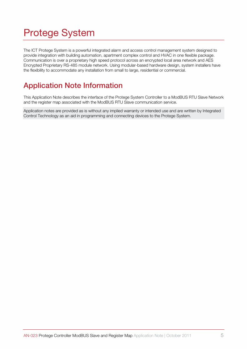
The ICT Protege System is a powerful integrated alarm and access control management system designed to provide integration with building automation, apartment complex control and HVAC in one flexible package. Communication is over a proprietary high speed protocol across an encrypted local area network and AES Encrypted Proprietary RS-485 module network. Using modular-based hardware design, system installers have the flexibility to accommodate any installation from small to large, residential or commercial.
Application Note Information This Application Note describes the interface of the Protege System Controller to a ModBUS RTU Slave Network and the register map associated with the ModBUS RTU Slave communication service.
Application notes are provided as is without any implied warranty or intended use and are written by Integrated Control Technology as an aid in programming and connecting devices to the Protege System.
6 AN-023 Protege Controller ModBUS Slave and Register Map Application Note | October 2011
About ModBUS
The following information describes the operation of Modbus as it relates to the Protege System Controller. For more detailed information on Modbus, you may also refer to the Modicon ModBUS Reference Guide, PI-MBUS-300 Rev J, available via download from www.public.modicon.com.
The ModBUS protocol provides an industry standard method that ModBUS devices use for parsing messages. This protocol was developed by Modicon, Incorporated, for industrial automation systems and Modicon programmable controllers. ModBUS devices communicate using a master-slave technique in which only one device (the master) can initiate transactions (called queries). The other devices (slaves) respond by supplying the requested data to the master, or by taking the action requested in the query. A slave is any peripheral device (I/O transducer, valve, network drive, or other measuring device) which processes information and sends its output to the master using ModBUS. The Protege System Controller operates as a slave device, while a typical master device is a host computer running appropriate application software.
Masters can address individual slaves, or can initiate a broadcast message to all slaves. Slaves return a response to all queries addressed to them individually, but do not respond to broadcast queries. A master’s query consists of a slave address (or broadcast address), a function code defining the requested action, any required data, and an error checking field. A slave’s response consists of fields confirming the action taken, any data to be returned, and an error checking field. Note that the query and response both include a device address, plus a function code, plus applicable data, and an error checking field. If no error occurs, the slave’s response contains the data requested. If an error occurs in the query received, or if the slave is unable to perform the action requested, the slave will return an exception message as its response (see ModBUS Exceptions on the modbus.org website).
The error check field of the message frame allows the master to confirm that the contents of the message are valid. Additionally, parity checking is also applied to each transmitted character in its data frame.
ModBUS Register Maps ModBUS devices usually include a Register Map. ModBUS functions operate on register map registers to monitor, configure, and control module I/O. A register map is provided in this document for the Protege System Controller. You will also find it helpful to refer to the register map as you review the functionality that is required to be integrated with the Protege System Controller.
ModBUS registers are organized into reference types identified by the leading number of the reference address:
Register Reference Description 0xxxxx Read/Write Discrete Outputs or Coils. A 0x reference address is used to drive output data to a digital output channel.
1xxxxx Read Discrete Inputs. The ON/OFF status of a 1x reference address is controlled by the corresponding digital input channel.
3xxxxx Read Input Registers. A 3x reference register contains a 16-bit number received from an external source—e.g. an analog input signal.
4xxxxx Read/Write Output or Holding Registers. A 4x register is used to store 16-bits of numerical data (binary or decimal), or to send the data from the CPU to an analog output channel.
Not all ModBUS functions operate on register map registers. For example, the Report Slave ID and Reset Slave functions do not operate on register map locations.
Standard ModBUS networks employ one of two types of transmission modes. ASCII Mode, or RTU Mode. The transmission mode defines the bit contents of the message bytes transmitted along the network, and how the message information is to be packed into the message stream and decoded.
The mode of transmission is selected within the Protege ModBUS Slave Service along with other serial port communication parameters (address, baud rate, parity, etc.) as part of the service configuration. The ModBUS RTU Slave Service in the Protege System Controller supports the Binary Mode only and ASCII mode is not supported due to the increased processing time required.
AN-023 Protege Controller ModBUS Slave and Register Map Application Note | October 2011 7
Service Configuration
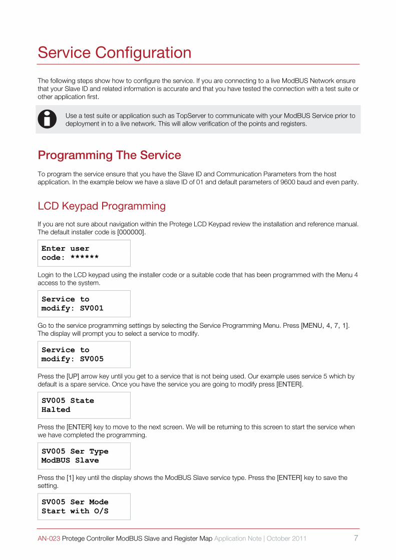
The following steps show how to configure the service. If you are connecting to a live ModBUS Network ensure that your Slave ID and related information is accurate and that you have tested the connection with a test suite or other application first.
i
Use a test suite or application such as TopServer to communicate with your ModBUS Service prior to deployment in to a live network. This will allow verification of the points and registers.
Programming The Service To program the service ensure that you have the Slave ID and Communication Parameters from the host application. In the example below we have a slave ID of 01 and default parameters of 9600 baud and even parity.
LCD Keypad Programming
If you are not sure about navigation within the Protege LCD Keypad review the installation and reference manual. The default installer code is [000000].
Enter user code: ******
Login to the LCD keypad using the installer code or a suitable code that has been programmed with the Menu 4 access to the system.
Service to modify: SV001
Go to the service programming settings by selecting the Service Programming Menu. Press [MENU, 4, 7, 1]. The display will prompt you to select a service to modify.
Service to modify: SV005
Press the [UP] arrow key until you get to a service that is not being used. Our example uses service 5 which by default is a spare service. Once you have the service you are going to modify press [ENTER].
SV005 State Halted
Press the [ENTER] key to move to the next screen. We will be returning to this screen to start the service when we have completed the programming.
SV005 Ser Type ModBUS Slave
Press the [1] key until the display shows the ModBUS Slave service type. Press the [ENTER] key to save the setting.
SV005 Ser Mode Start with O/S

8 AN-023 Protege Controller ModBUS Slave and Register Map Application Note | October 2011
Press the [1] key until the display shows the Start with O/S option. This will mean that if the system controller is reset or powered down the service will start automatically. Press the [ENTER] key to save the setting and move to the next screen.
SV005 Port Ext Port 1
Press the [1] key until the display shows the Serial Port that will be used to communicate with the ModBUS Network. In our configuration we are using External Port 1. Press the [ENTER] key to save the setting and move to the next screen.
SV005 Speed 9600
Press the [1] key until the display shows the communication speed Serial Port that will be used to communicate with the ModBUS Network. In our configuration we are using 9600 bits per second. Press the [ENTER] key to save the setting and move to the next screen.
SV005 Parity Even Parity
Press the [1] key until the display shows the parity that will be used to communicate with the ModBUS Network. In our configuration we are using Even Parity. Press the [ENTER] key to save the setting and move to the next screen.
SV005 Device address: 01
Use the numerical keys and the [2] and [3] key to enter the hexadecimal address that will be used as the device ID when communicating on the ModBUS Slave Network. Press the [ENTER] key to save the setting and move to the next screen.
SV005 Data [********]
Use the numerical keys from [1] to [8] to enable options. We are using the default options. Refer to the Protege System Controller Reference Manual for a list of these options and configurations. Press the [ENTER] key to save the setting and move to the next screen.
SV005 Poll fail time: 030 secs
Use the numerical keys to enter a poll failure time. This is a time that the system controller will allow no communication to occur without activating a poll failure alarm and alarming the ModBUS failure trouble zone. Press the [ENTER] key to save the setting and move to the next screen.
SV005 Poll fail pgm: --000:00
The poll fail PGM will activate if communication has not occurred for the poll fail time. If the poll fail option is not used do not program a PGM. Press the [ENTER] key to save the setting and move to the next screen.
AN-023 Protege Controller ModBUS Slave and Register Map Application Note | October 2011 9
Starting The Service Once you have pressed the [ENTER] key at the last screen press it until you see the service state display this is the first screen after the service to modify screen. Press the [1] key to start the service.
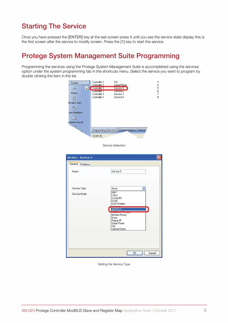
Protege System Management Suite Programming Programming the services using the Protege System Management Suite is accomplished using the services option under the system programming tab in the shortcuts menu. Select the service you want to program by double clicking the item in the list.
Service Selection
Setting the Service Type

10 AN-023 Protege Controller ModBUS Slave and Register Map Application Note | October 2011
After the selection of the service type you will be prompted to close and open the service again this is so the application can redraw the dialog box with the options that are defined for that service type.
Setting the Start with Operating System Operation
General Settings
To start the service from the Protege System Management Suite right click on the service number and select the start option from the menu.

AN-023 Protege Controller ModBUS Slave and Register Map Application Note | October 2011 11
Register Configuration
The following register map defines each coil, input and register that is available in the Protege System Controller. Any registers that are not defined should be treated as a reserved location and not used for any other purpose.
Map Structure Many of the registers within the Protege System Controller are mapped using standard registers this allows data to be sent in the raw binary form. As an alternative the trouble zones and zones are mapped using the Input Type and they provide a single bit value for alarm and closed. Programmable outputs are mapped to type coils unless the zone coil option is set which allows zones to be opened and closed from a ModBUS device for reporting.
Physical PGM Outputs Coil Address Map Coils are Boolean values (1 or 0) that are used to typically represent an output device. Coils can be controlled and can also return a status dependent on the attached or associated device. The following shows the mapping between the Coil address and outputs on the Protege System Controller and Modules. There are also some coils that provide the ability to control doors and automation outputs in the Protege System Controller.
System Controller PGM Output Coils
There is only one control panel per ModBUS configuration and this will allow the control and status of the 4 on board PGM Outputs.
PGM Number Function Read / Write
ModBUS Coil Number
CP001:01 Bell 1 Siren Output
Coil Read
Status Value 0 = PGM is Off
1 = PGM is On
Coil Write
Control Value 0 = Deactivate PGM
1 = Activate PGM
RD+WR 00001
CP001:02 Bell 2 Siren Output RD+WR 00002
CP001:03 PGM 3 Output RD+WR 00003
CP001:04 PGM 4 Output RD+WR 00004
12 AN-023 Protege Controller ModBUS Slave and Register Map Application Note | October 2011
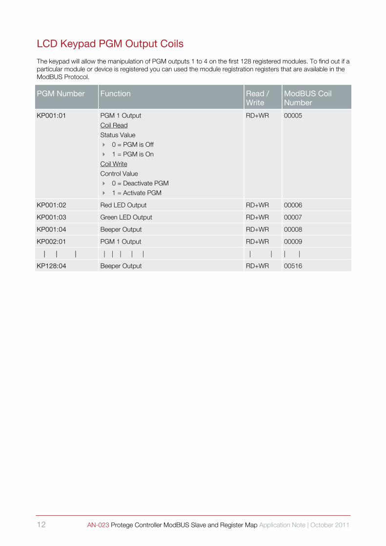
LCD Keypad PGM Output Coils
The keypad will allow the manipulation of PGM outputs 1 to 4 on the first 128 registered modules. To find out if a particular module or device is registered you can used the module registration registers that are available in the ModBUS Protocol.
PGM Number Function Read / Write
ModBUS Coil Number
KP001:01 PGM 1 Output
Coil Read
Status Value 0 = PGM is Off
1 = PGM is On
Coil Write
Control Value 0 = Deactivate PGM
1 = Activate PGM
RD+WR 00005
KP001:02 Red LED Output RD+WR 00006
KP001:03 Green LED Output RD+WR 00007
KP001:04 Beeper Output RD+WR 00008
KP002:01 PGM 1 Output RD+WR 00009
| | | | | | | | | | | |
KP128:04 Beeper Output RD+WR 00516
AN-023 Protege Controller ModBUS Slave and Register Map Application Note | October 2011 13
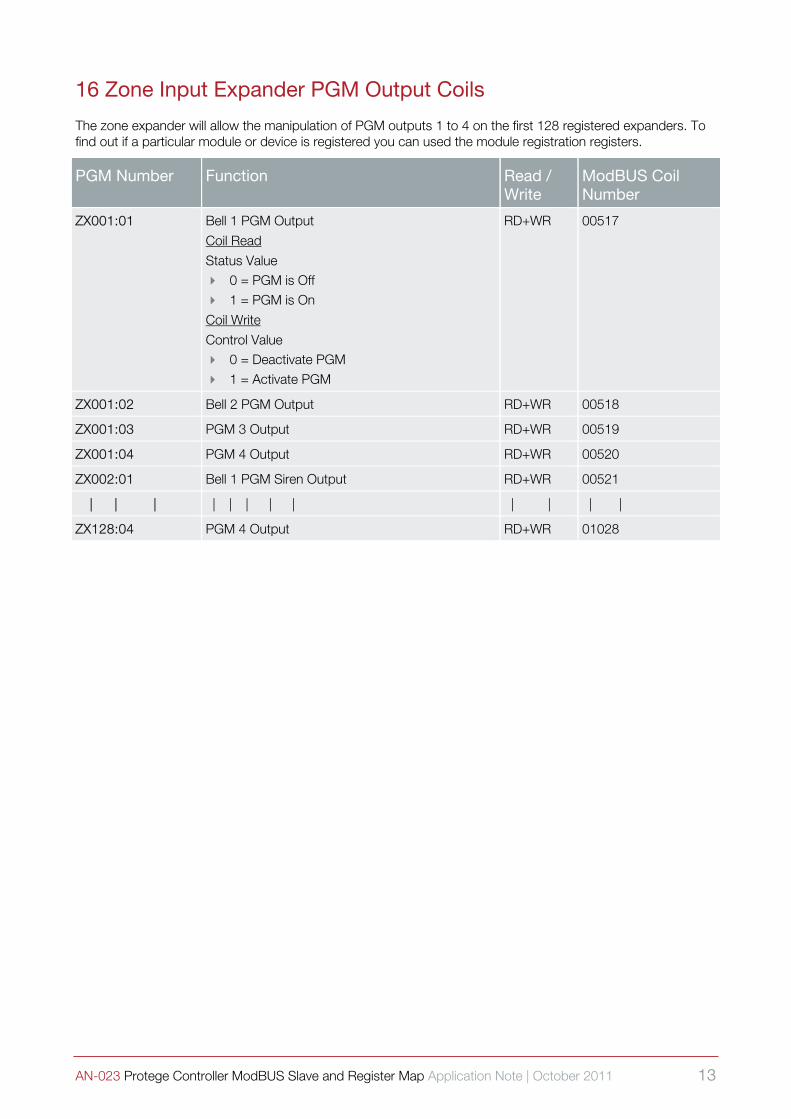
16 Zone Input Expander PGM Output Coils
The zone expander will allow the manipulation of PGM outputs 1 to 4 on the first 128 registered expanders. To find out if a particular module or device is registered you can used the module registration registers.
PGM Number Function Read / Write
ModBUS Coil Number
ZX001:01 Bell 1 PGM Output
Coil Read
Status Value 0 = PGM is Off
1 = PGM is On
Coil Write
Control Value 0 = Deactivate PGM
1 = Activate PGM
RD+WR 00517
ZX001:02 Bell 2 PGM Output RD+WR 00518
ZX001:03 PGM 3 Output RD+WR 00519
ZX001:04 PGM 4 Output RD+WR 00520
ZX002:01 Bell 1 PGM Siren Output RD+WR 00521
| | | | | | | | | | | |
ZX128:04 PGM 4 Output RD+WR 01028
14 AN-023 Protege Controller ModBUS Slave and Register Map Application Note | October 2011
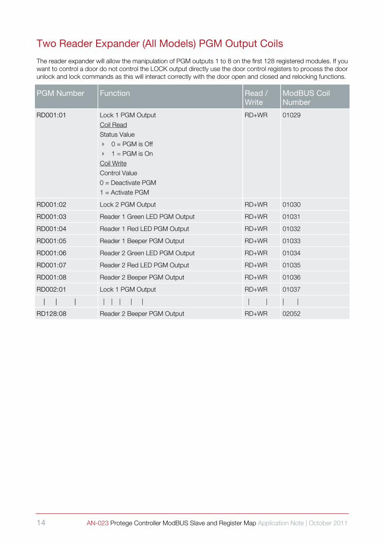
Two Reader Expander (All Models) PGM Output Coils
The reader expander will allow the manipulation of PGM outputs 1 to 8 on the first 128 registered modules. If you want to control a door do not control the LOCK output directly use the door control registers to process the door unlock and lock commands as this will interact correctly with the door open and closed and relocking functions.
PGM Number Function Read / Write
ModBUS Coil Number
RD001:01 Lock 1 PGM Output
Coil Read
Status Value 0 = PGM is Off
1 = PGM is On
Coil Write
Control Value
0 = Deactivate PGM
1 = Activate PGM
RD+WR 01029
RD001:02 Lock 2 PGM Output RD+WR 01030
RD001:03 Reader 1 Green LED PGM Output RD+WR 01031
RD001:04 Reader 1 Red LED PGM Output RD+WR 01032
RD001:05 Reader 1 Beeper PGM Output RD+WR 01033
RD001:06 Reader 2 Green LED PGM Output RD+WR 01034
RD001:07 Reader 2 Red LED PGM Output RD+WR 01035
RD001:08 Reader 2 Beeper PGM Output RD+WR 01036
RD002:01 Lock 1 PGM Output RD+WR 01037
| | | | | | | | | | | |
RD128:08 Reader 2 Beeper PGM Output RD+WR 02052

AN-023 Protege Controller ModBUS Slave and Register Map Application Note | October 2011 15
16 PGM Output Expander PGM Output Coils
The PGM output expander will allow the manipulation of PGM outputs 1 to 16 on the first 128 registered modules.
PGM Number Function Read / Write
ModBUS Coil Number
PX001:01 PGM 1 Output
Coil Read
Status Value 0 = PGM is Off
1 = PGM is On
Coil Write
Control Value 0 = Deactivate PGM
1 = Activate PGM
RD+WR 02053
PX001:02 PGM 2 Output RD+WR 02054
PX001:03 PGM 3 Output RD+WR 02055
PX001:04 PGM 4 Output RD+WR 02056
PX001:05 PGM 5 Output RD+WR 02057
PX001:06 PGM 6 Output RD+WR 02058
PX001:07 PGM 7 Output RD+WR 02059
PX001:08 PGM 8 Output RD+WR 02060
PX001:09 PGM 9 Output RD+WR 02061
PX001:10 PGM 10 Output RD+WR 02062
PX001:11 PGM 11 Output RD+WR 02063
PX001:12 PGM 12 Output RD+WR 02064
PX001:13 PGM 13 Output RD+WR 02065
PX001:14 PGM 14 Output RD+WR 02066
PX001:15 PGM 15 Output RD+WR 02067
PX001:16 PGM 16 Output RD+WR 02068
PX002:01 PGM 1 Output RD+WR 02069
| | | | | | | | | | | |
PX128:16 PGM 16 Output RD+WR 04100
16 AN-023 Protege Controller ModBUS Slave and Register Map Application Note | October 2011
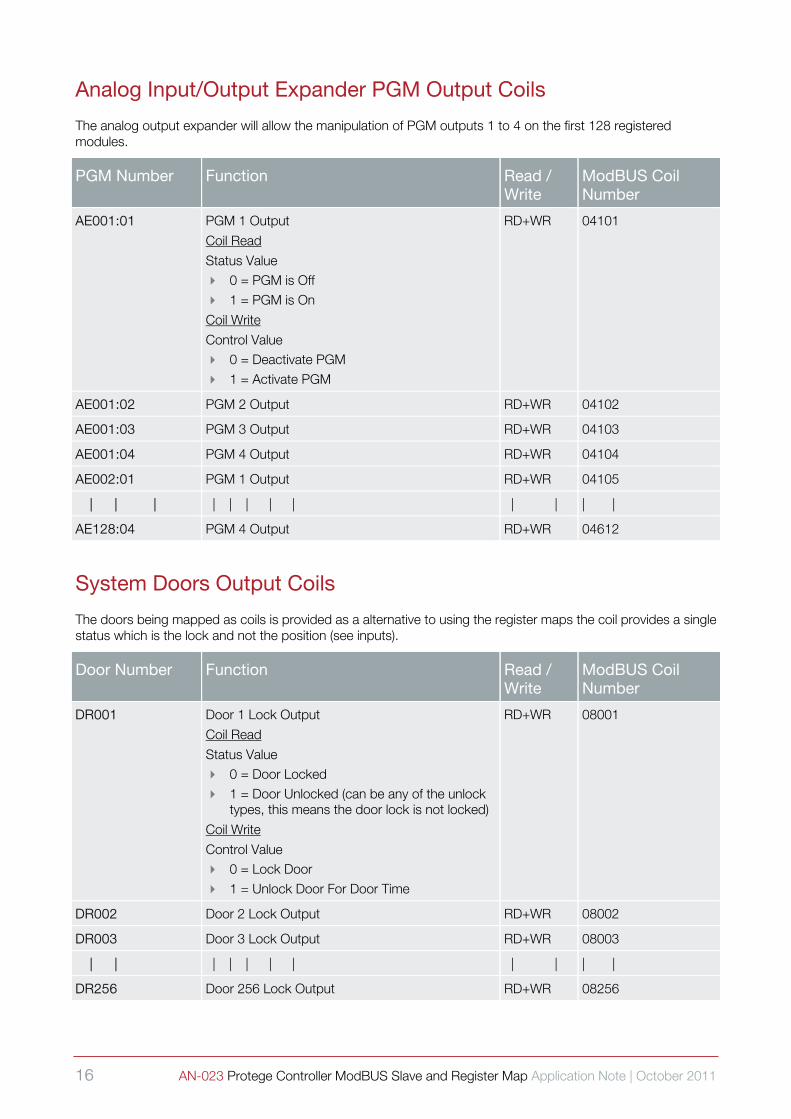
Analog Input/Output Expander PGM Output Coils
The analog output expander will allow the manipulation of PGM outputs 1 to 4 on the first 128 registered modules.
PGM Number Function Read / Write
ModBUS Coil Number
AE001:01 PGM 1 Output
Coil Read
Status Value 0 = PGM is Off
1 = PGM is On
Coil Write
Control Value 0 = Deactivate PGM
1 = Activate PGM
RD+WR 04101
AE001:02 PGM 2 Output RD+WR 04102
AE001:03 PGM 3 Output RD+WR 04103
AE001:04 PGM 4 Output RD+WR 04104
AE002:01 PGM 1 Output RD+WR 04105
| | | | | | | | | | | |
AE128:04 PGM 4 Output RD+WR 04612
System Doors Output Coils
The doors being mapped as coils is provided as a alternative to using the register maps the coil provides a single status which is the lock and not the position (see inputs).
Door Number Function Read / Write
ModBUS Coil Number
DR001 Door 1 Lock Output
Coil Read
Status Value 0 = Door Locked
1 = Door Unlocked (can be any of the unlock types, this means the door lock is not locked)
Coil Write
Control Value 0 = Lock Door
1 = Unlock Door For Door Time
RD+WR 08001
DR002 Door 2 Lock Output RD+WR 08002
DR003 Door 3 Lock Output RD+WR 08003
| | | | | | | | | | |
DR256 Door 256 Lock Output RD+WR 08256

AN-023 Protege Controller ModBUS Slave and Register Map Application Note | October 2011 17
System Automation Control Output Coils
The ability to map automation points as a coil is provided as an alternative to using the register maps. The status returned reflects the automation point status. Automation points and ModBUS can be used to create a ModBUS to C-Bus® Communication Bridge.
Door Number Function Read / Write
ModBUS Coil Number
AT001 Automation Control 1 Output
Coil Read
Status Value 0 = Automation Point is Off
1 = Automation Point is On (could be any activation state)
Coil Write
Control Value 0 = Turn Off Automation Point
1 = Turn On Automation Point
RD+WR 08257
AT002 Automation Control 2 Output RD+WR 08258
AT003 Automation Control 3 Output RD+WR 08259
| | | | | | | | | | | | |
AT256 Automation Control 256 Output RD+WR 08512
Zone Coil Translation Functions As mentioned in the coils section above they are Boolean values (1 or 0) that are used to typically represent an output device however in the Protege System Controller there is the ability to enable the zone to coil translation option to allow a coil to be mapped to a zone input (virtual, no device is present at the location).
The ability to map a coil to a physical or virtual zone on the Protege System Controller allows a coil to be activated from the ModBUS host which will then cause an alarm or action to occur on the Protege System. This might be used for reporting alarms from a SCADA system or performing some other automation or integrated action to occur.
Reading from the coil that is within one of the zone translation values will return the status of the zone input and not a memory region or coil value. The zone will return a ‘1’ to the coil register for open / alarm and ‘0’ for closed / restored.
i
To allow these coils to be written and the subsequent zone to be opened or closed as a result of the request the option must be set to allow this to occur in the service data options. When writing a coil that is translated to a zone setting a coil value of ‘1’ will open the zone and ‘0’ will restore the zone. Writing a value that is already set for the zone will result in no change taking place on the zone and no event occurring.
Control Panel Zone Coil Translation Functions
The control panel zones can NOT be controlled from the ModBUS interface using the Zone Coil Translation Functions.
18 AN-023 Protege Controller ModBUS Slave and Register Map Application Note | October 2011
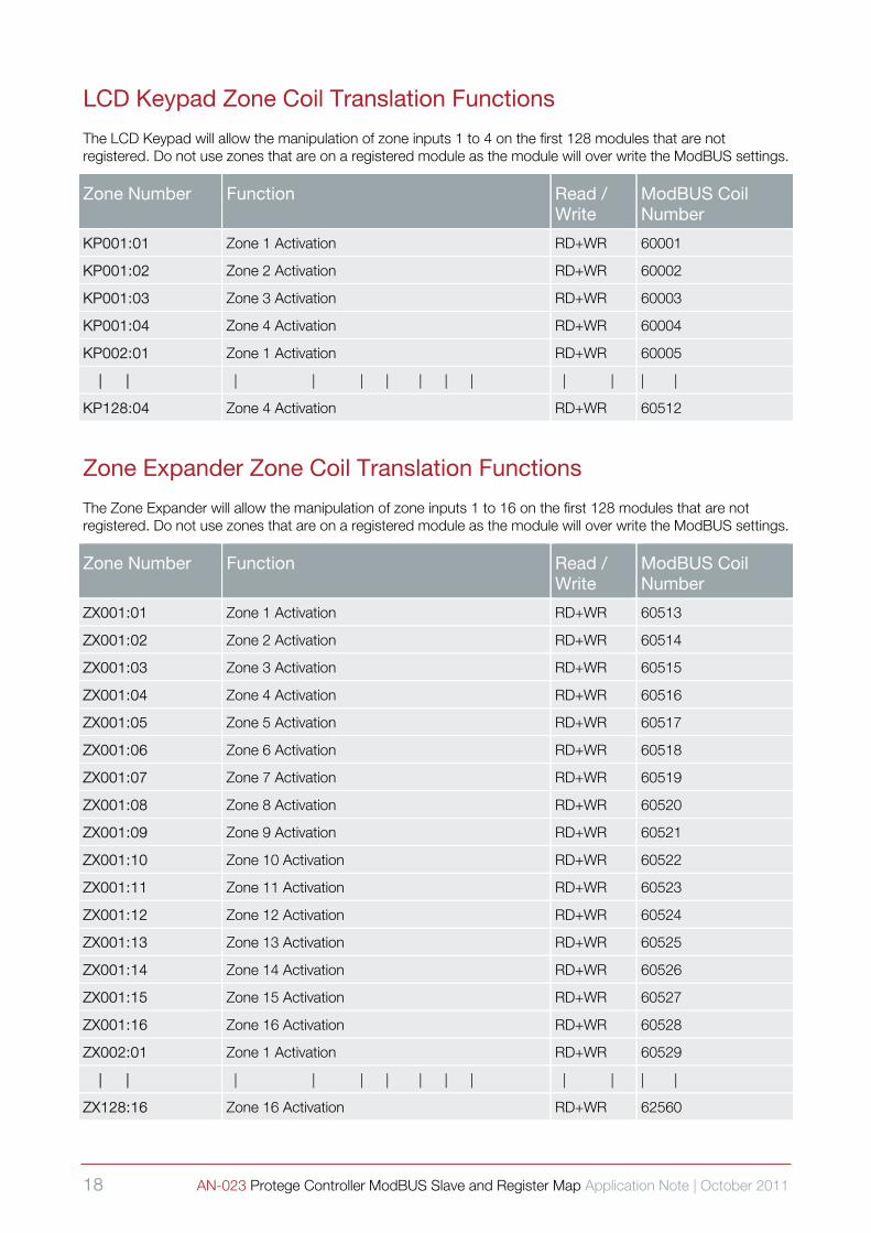
LCD Keypad Zone Coil Translation Functions
The LCD Keypad will allow the manipulation of zone inputs 1 to 4 on the first 128 modules that are not registered. Do not use zones that are on a registered module as the module will over write the ModBUS settings.
Zone Number Function Read / Write
ModBUS Coil Number
KP001:01 Zone 1 Activation RD+WR 60001
KP001:02 Zone 2 Activation RD+WR 60002
KP001:03 Zone 3 Activation RD+WR 60003
KP001:04 Zone 4 Activation RD+WR 60004
KP002:01 Zone 1 Activation RD+WR 60005
| | | | | | | | | | | | |
KP128:04 Zone 4 Activation RD+WR 60512
Zone Expander Zone Coil Translation Functions
The Zone Expander will allow the manipulation of zone inputs 1 to 16 on the first 128 modules that are not registered. Do not use zones that are on a registered module as the module will over write the ModBUS settings.
Zone Number Function Read / Write
ModBUS Coil Number
ZX001:01 Zone 1 Activation RD+WR 60513
ZX001:02 Zone 2 Activation RD+WR 60514
ZX001:03 Zone 3 Activation RD+WR 60515
ZX001:04 Zone 4 Activation RD+WR 60516
ZX001:05 Zone 5 Activation RD+WR 60517
ZX001:06 Zone 6 Activation RD+WR 60518
ZX001:07 Zone 7 Activation RD+WR 60519
ZX001:08 Zone 8 Activation RD+WR 60520
ZX001:09 Zone 9 Activation RD+WR 60521
ZX001:10 Zone 10 Activation RD+WR 60522
ZX001:11 Zone 11 Activation RD+WR 60523
ZX001:12 Zone 12 Activation RD+WR 60524
ZX001:13 Zone 13 Activation RD+WR 60525
ZX001:14 Zone 14 Activation RD+WR 60526
ZX001:15 Zone 15 Activation RD+WR 60527
ZX001:16 Zone 16 Activation RD+WR 60528
ZX002:01 Zone 1 Activation RD+WR 60529
| | | | | | | | | | | | |
ZX128:16 Zone 16 Activation RD+WR 62560
AN-023 Protege Controller ModBUS Slave and Register Map Application Note | October 2011 19
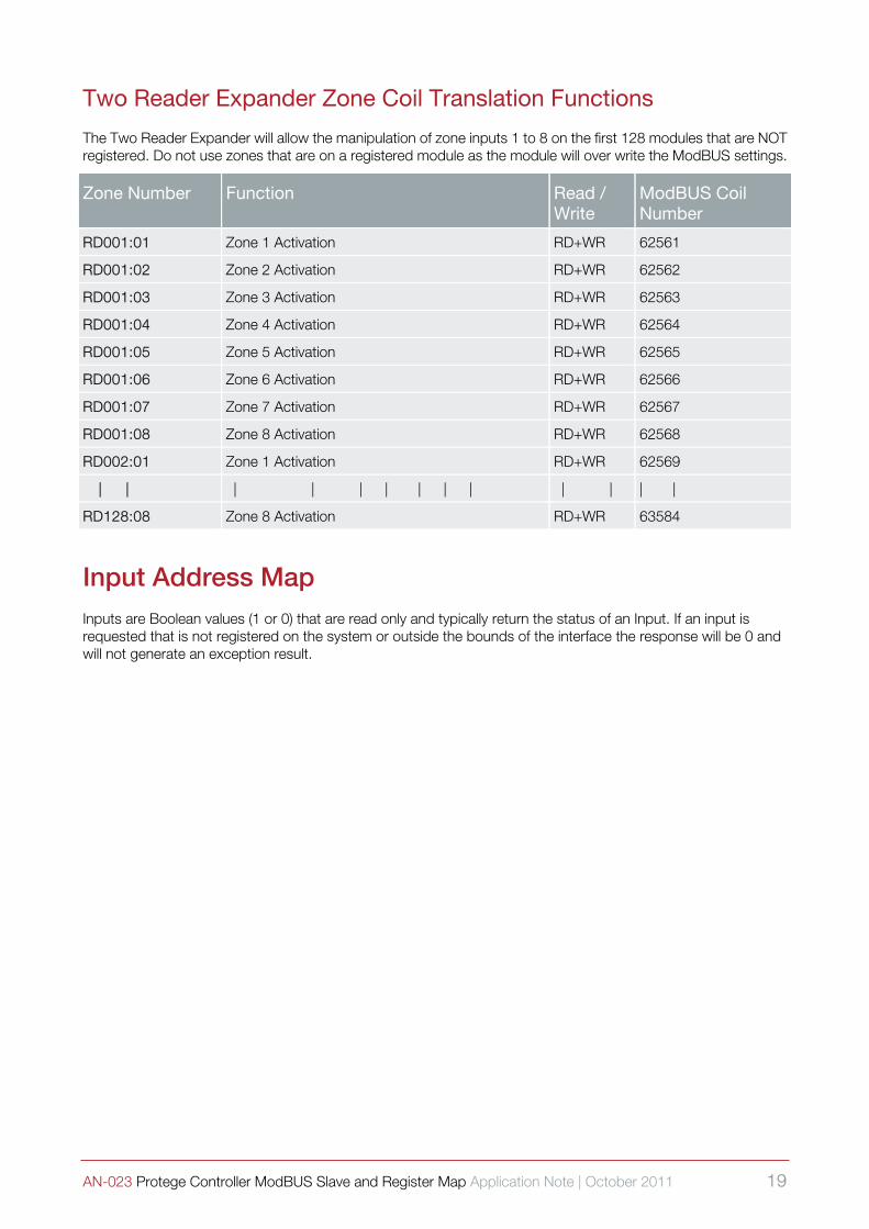
Two Reader Expander Zone Coil Translation Functions
The Two Reader Expander will allow the manipulation of zone inputs 1 to 8 on the first 128 modules that are NOT registered. Do not use zones that are on a registered module as the module will over write the ModBUS settings.
Zone Number Function Read / Write
ModBUS Coil Number
RD001:01 Zone 1 Activation RD+WR 62561
RD001:02 Zone 2 Activation RD+WR 62562
RD001:03 Zone 3 Activation RD+WR 62563
RD001:04 Zone 4 Activation RD+WR 62564
RD001:05 Zone 5 Activation RD+WR 62565
RD001:06 Zone 6 Activation RD+WR 62566
RD001:07 Zone 7 Activation RD+WR 62567
RD001:08 Zone 8 Activation RD+WR 62568
RD002:01 Zone 1 Activation RD+WR 62569
| | | | | | | | | | | | |
RD128:08 Zone 8 Activation RD+WR 63584
Input Address Map Inputs are Boolean values (1 or 0) that are read only and typically return the status of an Input. If an input is requested that is not registered on the system or outside the bounds of the interface the response will be 0 and will not generate an exception result.
20 AN-023 Protege Controller ModBUS Slave and Register Map Application Note | October 2011
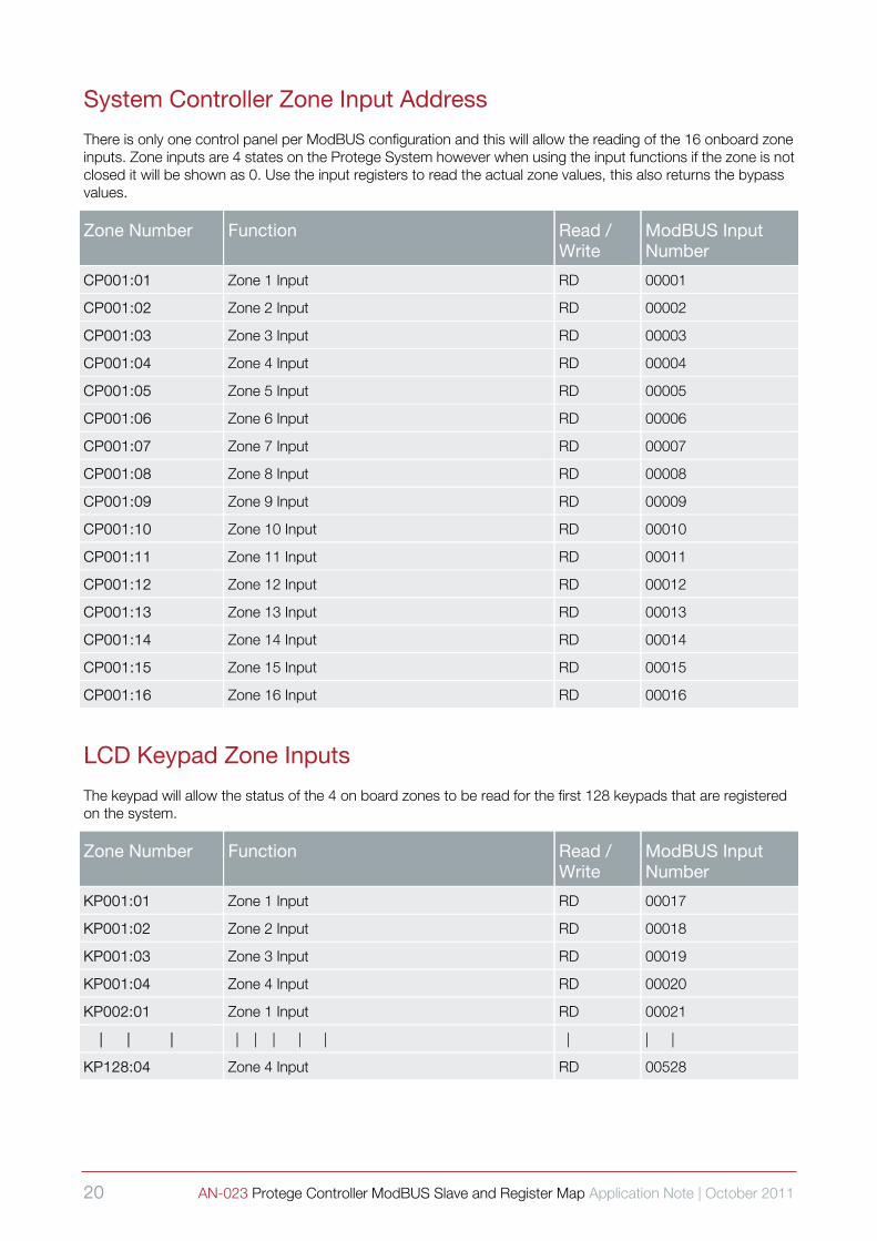
System Controller Zone Input Address
There is only one control panel per ModBUS configuration and this will allow the reading of the 16 onboard zone inputs. Zone inputs are 4 states on the Protege System however when using the input functions if the zone is not closed it will be shown as 0. Use the input registers to read the actual zone values, this also returns the bypass values.
Zone Number Function Read / Write
ModBUS Input Number
CP001:01 Zone 1 Input RD 00001
CP001:02 Zone 2 Input RD 00002
CP001:03 Zone 3 Input RD 00003
CP001:04 Zone 4 Input RD 00004
CP001:05 Zone 5 Input RD 00005
CP001:06 Zone 6 Input RD 00006
CP001:07 Zone 7 Input RD 00007
CP001:08 Zone 8 Input RD 00008
CP001:09 Zone 9 Input RD 00009
CP001:10 Zone 10 Input RD 00010
CP001:11 Zone 11 Input RD 00011
CP001:12 Zone 12 Input RD 00012
CP001:13 Zone 13 Input RD 00013
CP001:14 Zone 14 Input RD 00014
CP001:15 Zone 15 Input RD 00015
CP001:16 Zone 16 Input RD 00016
LCD Keypad Zone Inputs
The keypad will allow the status of the 4 on board zones to be read for the first 128 keypads that are registered on the system.
Zone Number Function Read / Write
ModBUS Input Number
KP001:01 Zone 1 Input RD 00017
KP001:02 Zone 2 Input RD 00018
KP001:03 Zone 3 Input RD 00019
KP001:04 Zone 4 Input RD 00020
KP002:01 Zone 1 Input RD 00021
| | | | | | | | | | |
KP128:04 Zone 4 Input RD 00528

AN-023 Protege Controller ModBUS Slave and Register Map Application Note | October 2011 21
16 Zone Input Expander Zone Inputs
The zone expander will allow the status of the 16 on board zones to be read for the first 128 expanders that are registered on the system.
Zone Number Function Read / Write
ModBUS Input Number
ZX001:01 Zone 1 Input RD 00529
ZX001:02 Zone 2 Input RD 00530
ZX001:03 Zone 3 Input RD 00531
ZX001:04 Zone 4 Input RD 00532
ZX001:05 Zone 5 Input RD 00533
ZX001:06 Zone 6 Input RD 00534
ZX001:07 Zone 7 Input RD 00535
ZX001:08 Zone 8 Input RD 00536
ZX001:09 Zone 9 Input RD 00537
ZX001:10 Zone 10 Input RD 00538
ZX001:11 Zone 11 Input RD 00539
ZX001:12 Zone 12 Input RD 00540
ZX001:13 Zone 13 Input RD 00541
ZX001:14 Zone 14 Input RD 00542
ZX001:15 Zone 15 Input RD 00543
ZX001:16 Zone 16 Input RD 00544
ZX002:01 Zone 1 Input RD 00545
| | | | | | | | | | |
ZX128:16 Zone 16 Input RD 02576
22 AN-023 Protege Controller ModBUS Slave and Register Map Application Note | October 2011
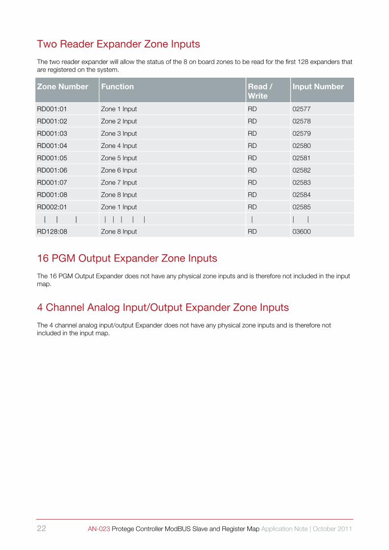
Two Reader Expander Zone Inputs
The two reader expander will allow the status of the 8 on board zones to be read for the first 128 expanders that are registered on the system.
Zone Number Function Read / Write
Input Number
RD001:01 Zone 1 Input RD 02577
RD001:02 Zone 2 Input RD 02578
RD001:03 Zone 3 Input RD 02579
RD001:04 Zone 4 Input RD 02580
RD001:05 Zone 5 Input RD 02581
RD001:06 Zone 6 Input RD 02582
RD001:07 Zone 7 Input RD 02583
RD001:08 Zone 8 Input RD 02584
RD002:01 Zone 1 Input RD 02585
| | | | | | | | | | |
RD128:08 Zone 8 Input RD 03600
16 PGM Output Expander Zone Inputs
The 16 PGM Output Expander does not have any physical zone inputs and is therefore not included in the input map.
4 Channel Analog Input/Output Expander Zone Inputs
The 4 channel analog input/output Expander does not have any physical zone inputs and is therefore not included in the input map.
AN-023 Protege Controller ModBUS Slave and Register Map Application Note | October 2011 23
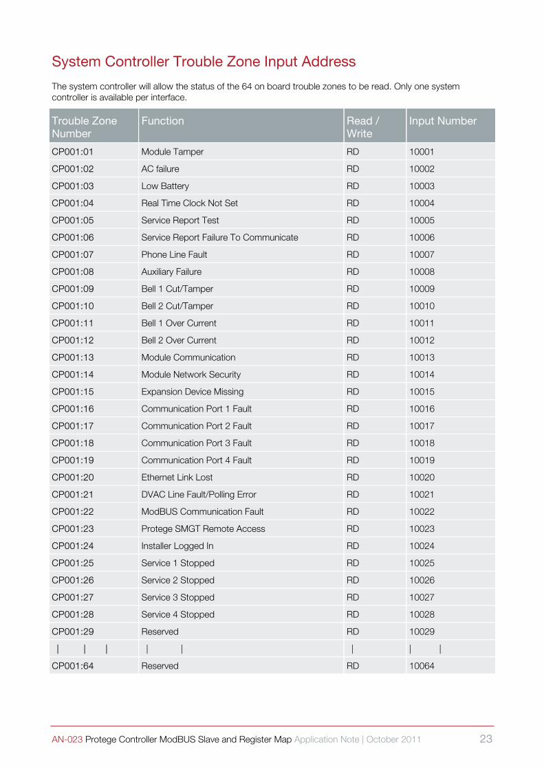
System Controller Trouble Zone Input Address
The system controller will allow the status of the 64 on board trouble zones to be read. Only one system controller is available per interface.
Trouble Zone Number
Function Read / Write
Input Number
CP001:01 Module Tamper RD 10001
CP001:02 AC failure RD 10002
CP001:03 Low Battery RD 10003
CP001:04 Real Time Clock Not Set RD 10004
CP001:05 Service Report Test RD 10005
CP001:06 Service Report Failure To Communicate RD 10006
CP001:07 Phone Line Fault RD 10007
CP001:08 Auxiliary Failure RD 10008
CP001:09 Bell 1 Cut/Tamper RD 10009
CP001:10 Bell 2 Cut/Tamper RD 10010
CP001:11 Bell 1 Over Current RD 10011
CP001:12 Bell 2 Over Current RD 10012
CP001:13 Module Communication RD 10013
CP001:14 Module Network Security RD 10014
CP001:15 Expansion Device Missing RD 10015
CP001:16 Communication Port 1 Fault RD 10016
CP001:17 Communication Port 2 Fault RD 10017
CP001:18 Communication Port 3 Fault RD 10018
CP001:19 Communication Port 4 Fault RD 10019
CP001:20 Ethernet Link Lost RD 10020
CP001:21 DVAC Line Fault/Polling Error RD 10021
CP001:22 ModBUS Communication Fault RD 10022
CP001:23 Protege SMGT Remote Access RD 10023
CP001:24 Installer Logged In RD 10024
CP001:25 Service 1 Stopped RD 10025
CP001:26 Service 2 Stopped RD 10026
CP001:27 Service 3 Stopped RD 10027
CP001:28 Service 4 Stopped RD 10028
CP001:29 Reserved RD 10029
| | | | | | | |
CP001:64 Reserved RD 10064
24 AN-023 Protege Controller ModBUS Slave and Register Map Application Note | October 2011
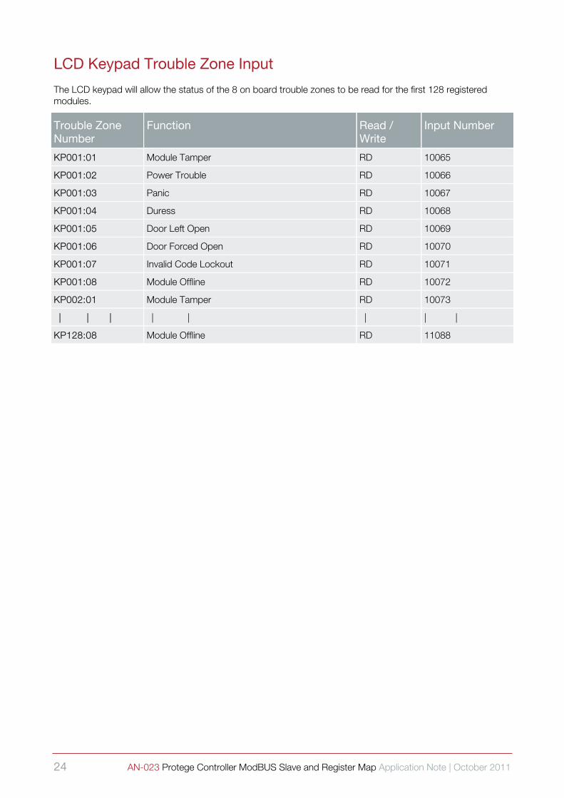
LCD Keypad Trouble Zone Input
The LCD keypad will allow the status of the 8 on board trouble zones to be read for the first 128 registered modules.
Trouble Zone Number
Function Read / Write
Input Number
KP001:01 Module Tamper RD 10065
KP001:02 Power Trouble RD 10066
KP001:03 Panic RD 10067
KP001:04 Duress RD 10068
KP001:05 Door Left Open RD 10069
KP001:06 Door Forced Open RD 10070
KP001:07 Invalid Code Lockout RD 10071
KP001:08 Module Offline RD 10072
KP002:01 Module Tamper RD 10073
| | | | | | | |
KP128:08 Module Offline RD 11088
AN-023 Protege Controller ModBUS Slave and Register Map Application Note | October 2011 25
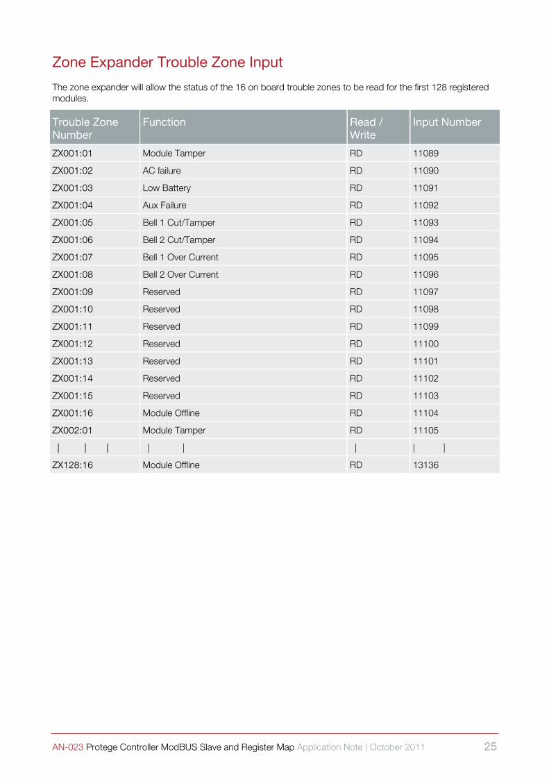
Zone Expander Trouble Zone Input
The zone expander will allow the status of the 16 on board trouble zones to be read for the first 128 registered modules.
Trouble Zone Number
Function Read / Write
Input Number
ZX001:01 Module Tamper RD 11089
ZX001:02 AC failure RD 11090
ZX001:03 Low Battery RD 11091
ZX001:04 Aux Failure RD 11092
ZX001:05 Bell 1 Cut/Tamper RD 11093
ZX001:06 Bell 2 Cut/Tamper RD 11094
ZX001:07 Bell 1 Over Current RD 11095
ZX001:08 Bell 2 Over Current RD 11096
ZX001:09 Reserved RD 11097
ZX001:10 Reserved RD 11098
ZX001:11 Reserved RD 11099
ZX001:12 Reserved RD 11100
ZX001:13 Reserved RD 11101
ZX001:14 Reserved RD 11102
ZX001:15 Reserved RD 11103
ZX001:16 Module Offline RD 11104
ZX002:01 Module Tamper RD 11105
| | | | | | | |
ZX128:16 Module Offline RD 13136
26 AN-023 Protege Controller ModBUS Slave and Register Map Application Note | October 2011
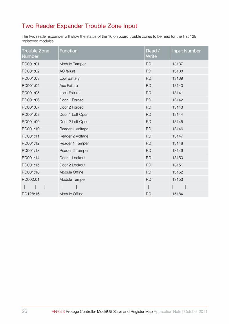
Two Reader Expander Trouble Zone Input
The two reader expander will allow the status of the 16 on board trouble zones to be read for the first 128 registered modules.
Trouble Zone Number
Function Read / Write
Input Number
RD001:01 Module Tamper RD 13137
RD001:02 AC failure RD 13138
RD001:03 Low Battery RD 13139
RD001:04 Aux Failure RD 13140
RD001:05 Lock Failure RD 13141
RD001:06 Door 1 Forced RD 13142
RD001:07 Door 2 Forced RD 13143
RD001:08 Door 1 Left Open RD 13144
RD001:09 Door 2 Left Open RD 13145
RD001:10 Reader 1 Voltage RD 13146
RD001:11 Reader 2 Voltage RD 13147
RD001:12 Reader 1 Tamper RD 13148
RD001:13 Reader 2 Tamper RD 13149
RD001:14 Door 1 Lockout RD 13150
RD001:15 Door 2 Lockout RD 13151
RD001:16 Module Offline RD 13152
RD002:01 Module Tamper RD 13153
| | | | | | | |
RD128:16 Module Offline RD 15184
AN-023 Protege Controller ModBUS Slave and Register Map Application Note | October 2011 27
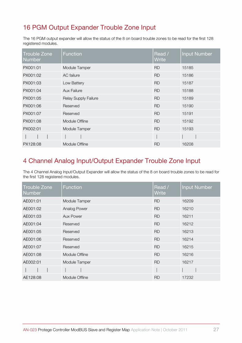
16 PGM Output Expander Trouble Zone Input
The 16 PGM output expander will allow the status of the 8 on board trouble zones to be read for the first 128 registered modules.
Trouble Zone Number
Function Read / Write
Input Number
PX001:01 Module Tamper RD 15185
PX001:02 AC failure RD 15186
PX001:03 Low Battery RD 15187
PX001:04 Aux Failure RD 15188
PX001:05 Relay Supply Failure RD 15189
PX001:06 Reserved RD 15190
PX001:07 Reserved RD 15191
PX001:08 Module Offline RD 15192
PX002:01 Module Tamper RD 15193
| | | | | | | |
PX128:08 Module Offline RD 16208
4 Channel Analog Input/Output Expander Trouble Zone Input
The 4 Channel Analog Input/Output Expander will allow the status of the 8 on board trouble zones to be read for the first 128 registered modules.
Trouble Zone Number
Function Read / Write
Input Number
AE001:01 Module Tamper RD 16209
AE001:02 Analog Power RD 16210
AE001:03 Aux Power RD 16211
AE001:04 Reserved RD 16212
AE001:05 Reserved RD 16213
AE001:06 Reserved RD 16214
AE001:07 Reserved RD 16215
AE001:08 Module Offline RD 16216
AE002:01 Module Tamper RD 16217
| | | | | | | |
AE128:08 Module Offline RD 17232

28 AN-023 Protege Controller ModBUS Slave and Register Map Application Note | October 2011
Input Register Address Map An input register is a 16 bit value that is read only and usually returns internal data that can not be written to. Internal registers are used to return information about the System Controller Version, Programmed Name and other system related configuration variables.
System Controller Analog Inputs
The system controller provides the analog values that are present on the controller’s inputs and power supply monitoring in the Input Register Map. This allows the values to be displayed on a screen or used within calculation functions.
Analog Number Function Read / Write
Input Number
AN001 Zone 1 Analog Value RD 00001
AN002 Zone 2 Analog Value RD 00002
AN003 Zone 3 Analog Value RD 00003
AN004 Zone 4 Analog Value RD 00004
AN005 Zone 5 Analog Value RD 00005
AN006 Zone 6 Analog Value RD 00006
AN007 Zone 7 Analog Value RD 00007
AN008 Zone 8 Analog Value RD 00008
AN009 Zone 9 Analog Value RD 00009
AN010 Zone 10 Analog Value RD 00010
AN011 Zone 11 Analog Value RD 00011
AN012 Zone 12 Analog Value RD 00012
AN013 Zone 13 Analog Value RD 00013
AN014 Zone 14 Analog Value RD 00014
AN015 Zone 15 Analog Value RD 00015
AN016 Zone 16 Analog Value RD 00016
AN017 Tamper Analog Value RD 00017
AN018 Auxiliary Supply Analog Value RD 00018
AN019 Battery Voltage Analog Value RD 00019
AN020 Battery Charge Current Analog Value RD 00020
AN021 AC Input Analog Value RD 00021
AN022 Channel Ground (Always 0) RD 00022

AN-023 Protege Controller ModBUS Slave and Register Map Application Note | October 2011 29
System Controller Information
The system controller provides the analog values that are present on the controller’s inputs and power supply monitoring in the Input Register Map. This allows the values to be displayed on a screen or used within calculation functions.
Description ID Function Read / Write
Input Number
NAME Controller Name
16 ASCII Bytes stored as high byte low byte order.
RD 00101
TIME Controller Time
Time returned as ASCII bytes in the format HH:MM:SS stored as high byte low byte order.
RD 00109
DATE Controller Date
Date returned as ASCII bytes in the format DD/MM/YYYY DOW stored as high byte low byte order. DOW is shown as _MON, _TUE etc where _ is a space character.
RD 00113
Schedule Status
The system controller provides the status of the internal schedules up to 512 if they are available which can be used for input in to a SCADA system or monitored by the application software. The upper byte of the data will contain the current holiday mask while the lower byte will contain the schedule status.
Schedule Number
Function Read / Write
Input Number
SC001 Schedule 1 Status
Upper Byte = Holiday Mask Bit 0 = Holiday Group 1 Valid
Bit 1 = Holiday Group 2 Valid
Bit 2 = Holiday Group 3 Valid
Bit 3 = Holiday Group 4 Valid
Bit 4 = Holiday Group 5 Valid
Bit 5 = Holiday Group 6 Valid Bit 6 = Holiday Group 7 Valid
Bit 7 = Holiday Group 8 Valid
Lower Byte = Schedule Status Bit 0 = Schedule Start Valid
Bit 1 = Schedule End Valid
Bit 2 = Schedule Valid
Bit 3 – 7 = Reserved
RD 00201
SC002 Schedule 2 Status RD 00202
| | | | | | | | |
SC512 Schedule 512 Status RD 00712

30 AN-023 Protege Controller ModBUS Slave and Register Map Application Note | October 2011
Register Address Map A register is a 16 bit value that is used to store data and can be read or written or combination of both. Registers are the preferred method of accessing data and provide a much larger amount of information about objects that are being accessed. For example PGM Outputs will provide a more detailed state information which shows what is controlled the output. Doors return both the lock and input states and areas return the 24 Hour and Normal Arming conditions as part of the register.
AN-023 Protege Controller ModBUS Slave and Register Map Application Note | October 2011 31
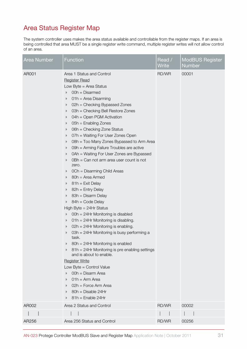
Area Status Register Map
The system controller uses makes the area status available and controllable from the register maps. If an area is being controlled that area MUST be a single register write command, multiple register writes will not allow control of an area.
Area Number Function Read / Write
ModBUS Register Number
AR001 Area 1 Status and Control
Register Read
Low Byte = Area Status 00h = Disarmed
01h = Area Disarming 02h = Checking Bypassed Zones
03h = Checking Bell Restore Zones
04h = Open PGM Activation
05h = Enabling Zones
06h = Checking Zone Status
07h = Waiting For User Zones Open 08h = Too Many Zones Bypassed to Arm Area
09h = Arming Failure Troubles are active
0Ah = Waiting For User Zones are Bypassed
0Bh = Can not arm area user count is not zero.
0Ch = Disarming Child Areas 80h = Area Armed
81h = Exit Delay
82h = Entry Delay
83h = Disarm Delay
84h = Code Delay
High Byte = 24Hr Status 00h = 24Hr Monitoring is disabled 01h = 24Hr Monitoring is disabling.
02h = 24Hr Monitoring is enabling.
03h = 24Hr Monitoring is busy performing a task.
80h = 24Hr Monitoring is enabled 81h = 24Hr Monitoring is pre enabling settings
and is about to enable.
Register Write
Low Byte = Control Value 00h = Disarm Area
01h = Arm Area
02h = Force Arm Area
80h = Disable 24Hr 81h = Enable 24Hr
RD/WR 00001
AR002 Area 2 Status and Control RD/WR 00002
| | | | | | | |
AR256 Area 256 Status and Control RD/WR 00256

32 AN-023 Protege Controller ModBUS Slave and Register Map Application Note | October 2011
Area Extended Status Register Map
The system controller makes the extended area status bits available on these registers and are packed in to the register as Boolean values.
Area Number Function Read / Write
ModBUS Register Number
AR001 Area 1 Extended Status
Low Byte = Status Bit 0 = When set the area is in an alarm
condition.
Bit 1 = When set the siren or bell has been activated for the area.
Bit 2 = When set the area is force armed. Bit 3 = When set the area is stay armed.
Bit 4 = When set the area is in a defer delay mode and is about to arm.
Bit 5 – 7 = Reserved
High Byte = Reserved always reads zero
RD 00257
AR002 Area 2 Extended Status RD 00258
| | | | | | |
AR256 Area 256 Extended Status RD 00512
Area User Current Count Register Map
The system controller uses counting for users within an area, this count can be read and reset using the following registers. A count that has been altered by the ModBUS interface may not update the count PGM for the area and caution should be used when writing count values for areas.
Area Number Function Read / Write
ModBUS Register Number
AR001 Area 1 Count Value 0-65535 RD/WR 00513
AR002 Area 2 Count Value 0-65535 RD/WR 00514
| | | | | | | |
AR256 Area 256 Count Value 0-65535 RD/WR 00768

AN-023 Protege Controller ModBUS Slave and Register Map Application Note | October 2011 33
Door Status Register Map
The system controller makes the door status available and controllable from the register maps. If a door is being controlled that door MUST be a single register write command, multiple register writes will not allow control of an door.
Door Number Function Read / Write
ModBUS Register Number
DR001 Door 1 Status and Control
Register Read
Low Byte = Door Position Status 00h = Door Closed
01h = Door Open 02h = Door Open Pre Alarm Warning
03h = Door Left Open
04h = Door Forced Open
High Byte = Door Lock Status 00h = Locked
01h = Unlocked
02h = Schedule Unlocked 03h = User Timed Unlocked
04h = User Latched Unlocked
05h = Request To Exit Unlocked
06h = Request To Enter Unlocked
07h = Menu Unlocked (Keypad)
08h = Unlocked By Area Status Control. 09h = Unlocked By Fire Alarm Function
Register Write
Low Byte = Control Value 00h = Lock Door
01h = Unlock Door
02h = Latch Unlock Door
RD/WR 00769
DR002 Door 2 Status and Control RD/WR 00770
| | | | | | | |
DR256 Door 256 Status and Control RD/WR 01024

34 AN-023 Protege Controller ModBUS Slave and Register Map Application Note | October 2011
PGM Outputs Register Map
The system controller allows PGM outputs to be controller from both the standard coil control functions or from registers. As a register is 16 bits wide the ability to control 16 PGM outputs with one register is achieved. When using a register to control PGM’s it is recommended that the state of the PGM’s is known prior to them being set as this will always set the PGM’s off or on dependent on the bit state in the register.
PGM Output Register
Function Read / Write
ModBUS Register Number
VR00001 Variable Register 1 RD/WR 50001
VR00002 Variable Register 2 RD/WR 50002
| | | | | | | | | | |
VR00512 Variable Register 512 RD/WR 50512
Variable Values Register Map
The system controller uses variable registers for the processing of analog input modules, programmable functions and other controllable settings in the Protege System. The Variable Registers can be written which will result in an analog output module being updated or read from to obtain the current channel information. Variables are also linked to programmable functions to get set points and hysterisis settings.
Variable Register Function Read / Write
ModBUS Register Number
VR00001 Variable Register 1 RD/WR 50001
VR00002 Variable Register 2 RD/WR 50002
| | | | | | | | | | |
VR00512 Variable Register 512 RD/WR 50512
Remote ModBUS Register Map
The system controller will map the remote registers that are used from the ModBUS remote register functions to the remote register values that are located in the upper register map. This allows a Protege System Controller to report alarms and messages to another Protege System Controller that is connected to a SCADA or HMI application without the need for specialist host modems and gateways.
Remote Register ID
Function Read / Write
ModBUS Register Number
RR00001 Remote Register 1 RD/WR 60001
RR00002 Remote Register 2 RD/WR 60002
| | | | | | | RD/WR | |
RR04096 Remote Register 4096 RD/WR 64096
i
To link remote ModBUS registers the remote ModBUS service must be used and the monitor phone service on the controller must be enabled for remote ModBUS reception. The option in the ModBUS service must also allow the remote registers to be read. Remote registers are common for all services.

AN-023 Protege Controller ModBUS Slave and Register Map Application Note | October 2011 35
References
ModBUS References ModBUS IDA Organisation
Modbus-IDA engages in a broad range of activities relating to the maintenance and proliferation of the Modbus protocol. Some of these activities include:
Participation in standards activities worldwide.
Leading the evolution of the Modbus protocol and its variants. Encouraging and assisting the use of Modbus across a broad spectrum of physical layers and transmission
media.
Maintaining and evolving a conformance testing program to insure greater interoperability of Modbus devices.
Providing information to users and supplers alike to help them be successful in their use of Modbus.
Engaging in educational and promotional efforts including trade shows, newsletters, this website, and other outreach activities.
http://www.modbus.org/ (http://www.modbus.org/)
Source Code For ModBUS Drivers Process Viewer For Linux and Windows
An independent process viewer that has a ModBUS Serial Communications interface and can be used with the Protege System Controller:
http://pvbrowser.de/pvbrowser/index.php?menu=8&topic=8&subtopic=4 (http://pvbrowser.de/pvbrowser/index.php?menu=8&topic=8&subtopic=4)

36 AN-023 Protege Controller ModBUS Slave and Register Map Application Note | October 2011
Contact
Integrated Control Technology welcomes all feedback.
Please visit our website (http://www.incontrol.co.nz) or use the contact information below.
Integrated Control Technology
P.O. Box 302-340
North Harbour Post Centre
Auckland
New Zealand
11 Canaveral Drive
Albany
North Shore City 0632
Auckland
New Zealand
Phone: +64-9-476-7124
Fax: +64-9-476-7128
Email: [email protected] or [email protected]
Web: www.incontrol.co.nz

Related Documents