The 35 th Chinese Control Conference (CCC) Protective Control and Fault Diagnosis of High-speed Railway Traction Power System Reported by: QIAN Qing-Quan Southwest Jiaotong University

Welcome message from author
This document is posted to help you gain knowledge. Please leave a comment to let me know what you think about it! Share it to your friends and learn new things together.
Transcript
The 35th Chinese Control Conference (CCC)
Protective Control and Fault Diagnosis of High-speed Railway
Traction Power System
Reported by: QIAN Qing-Quan
Southwest Jiaotong University
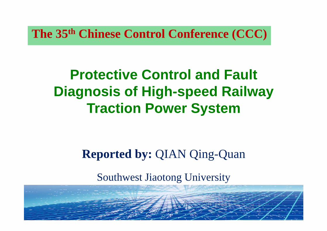
2Layout
11• Background and Traction Power System
22• Automation for High-speed Rail Traction
Substation
33• Detection and Diagnosis of Pantograph -
Catenary System
44• Prognostics and Health Management of
High-speed Rail Traction Substation

3
Background and Traction Power SystemPart I

41. Background and Traction power systemAt the end of 2015, the operating mileage of CRH is about19,000 km; which will reach to 30,000km at 2020.
1203300
19000
30000
2008 2009 2015 2020CRH Operating Mileage (km)
Two major problems of CRH:Two major problems of CRH:1. Scientific construction1. Scientific construction
2. Safety and high-efficient operation2. Safety and high-efficient operation
The 35th Chinese Control Conference
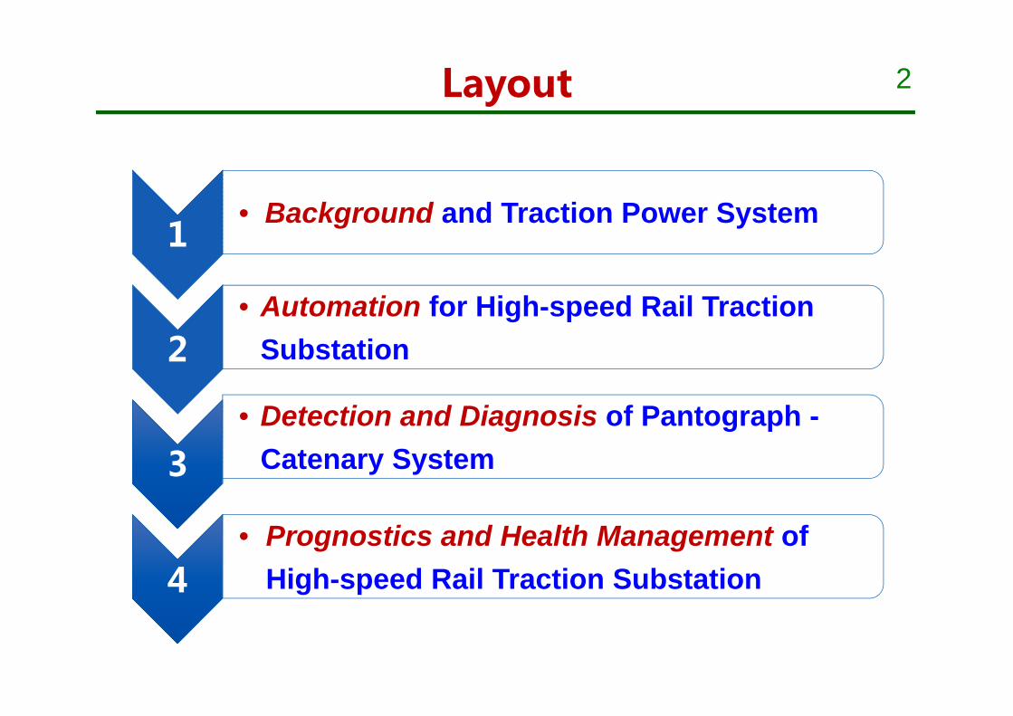
5CRH 3.0 “8 vertical 8 horizontal" railway net
1.0 “4 vertical 4 horizontal”2004~2008
2.0 “Long-term railway net plan(2008)”
3.0 “8 vertical 8 horizontal”2016~2030
6
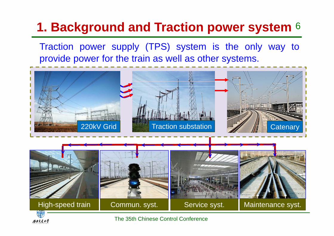
Traction power supply (TPS) system is the only way toprovide power for the train as well as other systems.
1. Background and Traction power system
Maintenance syst.High-speed train Commun. syst.
220kV Grid Traction substation Catenary
Service syst.
The 35th Chinese Control Conference

7
Jing-Hu high-speed rail (Shanghai Bureau)
Sections Faults in 2013 Faults in 2014 Fault Ratio
Suzhou Maintain 37 times 24 times 3.9 times / hundred km*yearBengbu Maintain 19 times 22 times
Adverse affect
Short circuit
Traffic delay
Acc
iden
ts
Operation Environment; Load Behavior; Special Structure
Fault ratio
1. Background and Traction power system Fast & accurate fault remove, power restore and reliable
operations of TPS are urgent needed
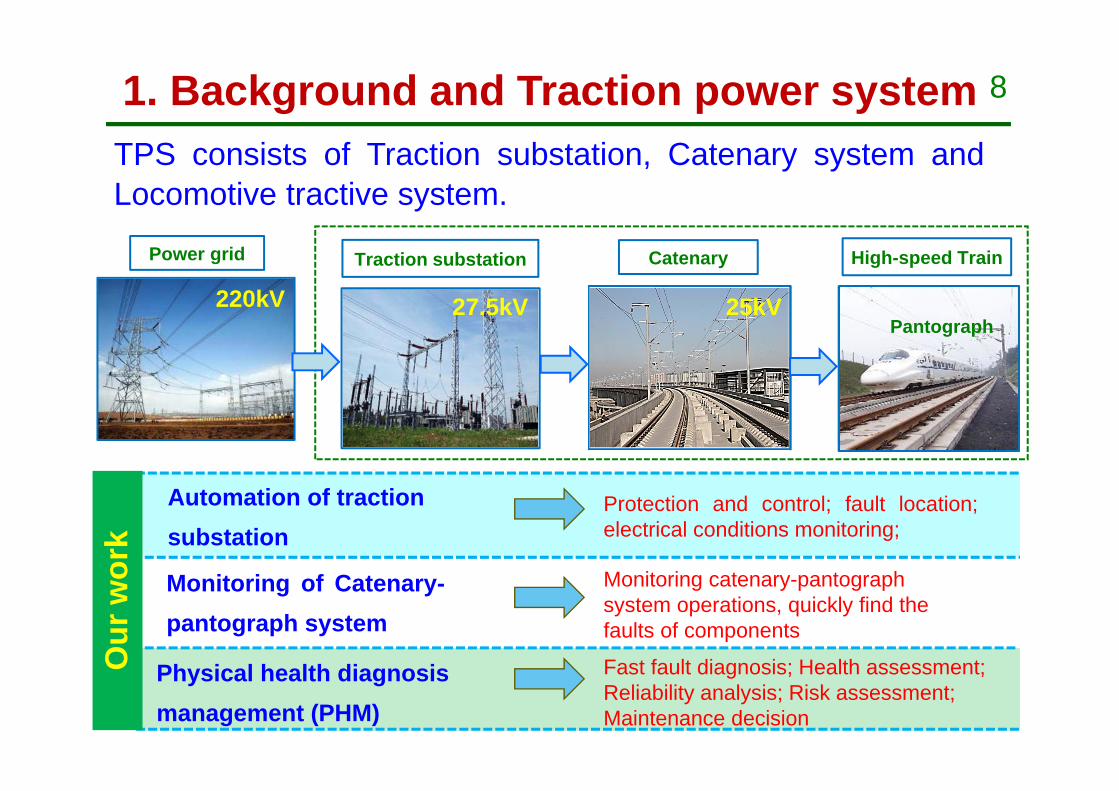
81. Background and Traction power systemTPS consists of Traction substation, Catenary system andLocomotive tractive system.
Automation of traction substation
Monitoring of Catenary-pantograph system
Physical health diagnosis management (PHM)
Protection and control; fault location;electrical conditions monitoring;
Monitoring catenary-pantograph system operations, quickly find the faults of components
Power grid CatenaryTraction substation High-speed Train
220kV 27.5kV 25kVPantograph
Fast fault diagnosis; Health assessment; Reliability analysis; Risk assessment; Maintenance decision
Our
wor
k

9
Automation for Traction SubstationPart II
10
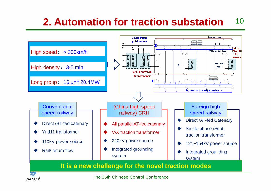
High speed:> 300km/h
High density:3-5 min
Long group:16 unit 20.4MW
Direct /BT-fed catenary
Ynd11 transformer
110kV power source
Rail/ return flow
(China high-speed railway) CRH
Foreign high speed railway
Direct /AT-fed Catenary
Single phase /Scott traction transformer
121~154kV power source
Integrated grounding system
Conventional speed railway
All parallel AT-fed catenary
V/X traction transformer
220kV power source
Integrated grounding system
2. Automation for traction substation
The 35th Chinese Control Conference
It is a new challenge for the novel traction modes
11
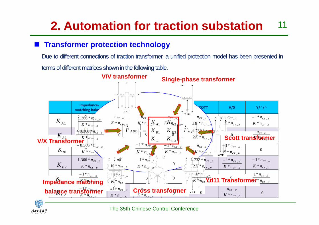
Impedance‐matching balance Y/△变 V/V) Single‐
phase SCOTT V/X Y/△/△
V/V transformer Single-phase transformer
Yd11 Transformer
Scott transformer
Cross transformerImpedance matchingbalance transformer
V/X Transformer
Due to different connections of traction transformer, a unified protection model has been presented in
terms of different matrices shown in the following table.
Transformer protection technology
1 2
1 2
1 2
A A
ABC B B
C C
K KI K K I
K K
ACT
CT
nKn
_
_
**1
_
_*CT
CT B
nK n
CCT
CT
nKn
_
_
**1
CCT
CT
nKn
_
_
**1
_
_*CT
CT A
nK n
BCT
CT
nKn
_
_
**1
BCT
CT
nKn
_
_
**1
CCT
CT
nKn
_
_
*
ACT
CT
nKn
_
_
*2
ACT
CT
nKn
_
_
*2*732.1
BCT
CT
nKn
_
_
*2
BCT
CT
nKn
_
_
*2*732.1
CCT
CT
nKn
_
_
**1
0
0
0 0
0
0
0
ACT
CT
nKn
_
_
*
BCT
CT
nKn
_
_
**1
ACT
CT
nKn
_
_
*
_
_
1**
CT
CT B
nK n
BCT
CT
nKn
_
_
**1
CCT
CT
nKn
_
_
*
ACT
CT
nKn
_
_
*
BCTnKn
_*
CCT
CT
nKn
_
_
**1
CCT
CT
nKn
_
_
**1
ACT
CT
nKn
_
_
**366.1
ACT
CT
nKn
_
_
**366.0
BCT
CT
nKn
_
_
**366.0
BCT
CT
nKn
_
_
**366.1
CCT
CT
nKn
_
_
**1
CCT
CT
nKn
_
_
**1
1AK
2AK
1BK
2BK
1CK
2CK
0
0
0
0
0
0
2. Automation for traction substation
The 35th Chinese Control Conference
12
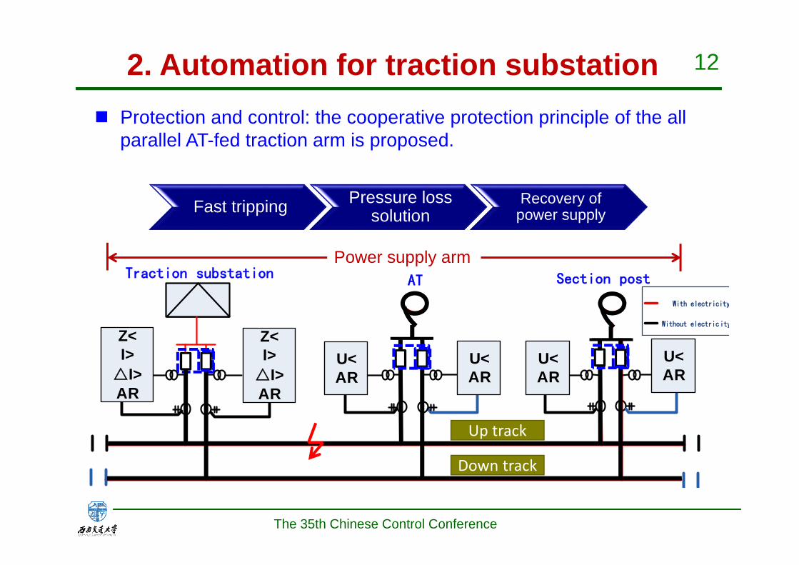
upstream
downstream
Z<I>
△I>AR
U<AR
AT Section post
Z<I>
△I>AR
U<AR
U<AR
U<AR
Traction substation
Fast tripping Pressure loss solution
Recovery of power supply
With electricity
Without electricity
Power supply arm
Protection and control: the cooperative protection principle of the all parallel AT-fed traction arm is proposed.
2. Automation for traction substation
Up track
Down track
The 35th Chinese Control Conference
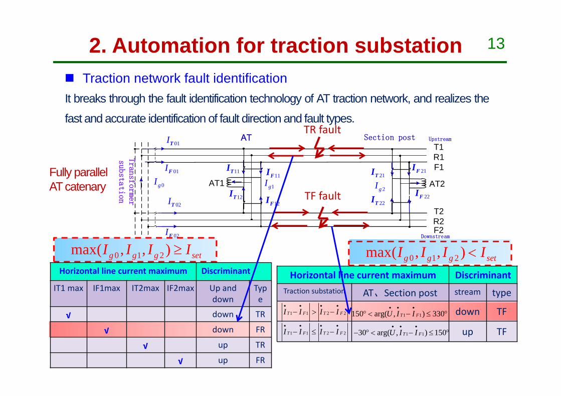
13
0 1 2max( , , )g g g setI I I I
T1
AT1
AT Section post
AT2
T2
F2
F1
R2
R1
01IT
01IF
02IF
11FI
02IT
11TI
12TI12FI
21FI21TI
22TI 22FI0gI
1gI2gI
Upstream
Downstream
Transformer
substation
TR fault
TF fault
0 1 2max( , , )g g g setI I I I
1 1 2 2T F T FI I I I
1 130 arg( , ) 150T FU I I
1 1 2 2T F T FI I I I
1 1150 arg( , ) 330T FU I I
Horizontal line current maximum DiscriminantTraction substation AT、Section post stream type
down TF
up TF
Horizontal line current maximum Discriminant
IT1 max IF1max IT2max IF2max Up and down
Type
√ down TR
√ down FR
√ up TR
√ up FR
It breaks through the fault identification technology of AT traction network, and realizes the
fast and accurate identification of fault direction and fault types.
Traction network fault identification
Fully parallel AT catenary
2. Automation for traction substation

14
0 2000 4000 6000 8000 10000f/Hz
0
50
100
幅值
Primary natural frequency fs
The fault wave reflects between fault point
and measuring device.
Additionally, because of the delayed effects
of the transmission line with finite length,
the fault traveling wave forms a spectrum
which consists of a series of harmonic
frequencies. It is called the natural
frequency of the fault traveling wave.
( 2 ) 0, 1, 2...4
S FS
k vf kd
,
We derived the relationship among natural frequency, and fault location and boundary condition is,
14/79页
2. Automation for traction substation
The 35th Chinese Control Conference
15
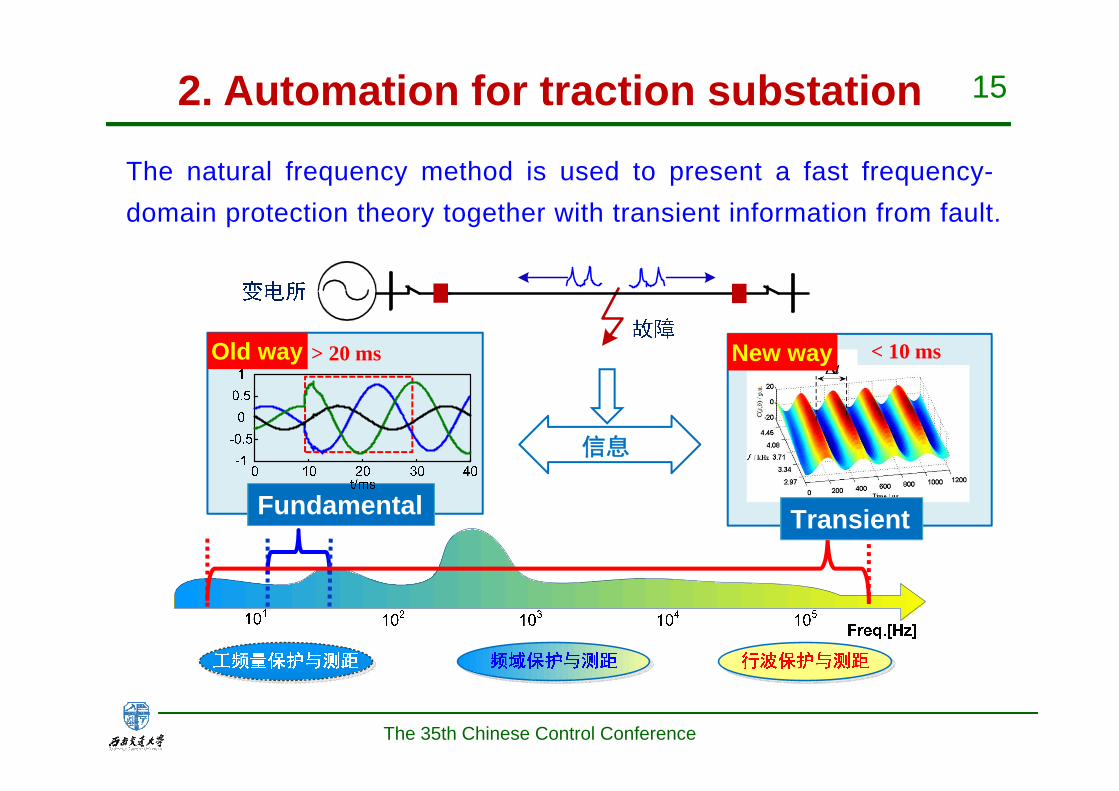
信息
Old way > 20 ms
Fundamental
New way
Transient
< 10 ms
2. Automation for traction substation
The natural frequency method is used to present a fast frequency-domain protection theory together with transient information from fault.
The 35th Chinese Control Conference

16
3. Promote the technique improvementEstablished 9 technique standards, in which 5 standards have been authorized.
2. Automation for traction substation
No Code Title
1 GB/T18038-2008 General specification of microprocessor-based protection equipment for electrified railway traction power supply system
2 TB10117-2008 Code for design of railway power supply dispatching system
3 TB/T3226-2010 Integrated automation system and devices of traction power supply substation for electrified railway
4 运电通信函2012-248 Technical scheme of communication network for railway power supply dispatching system
5 铁运函2012-136 Technical specification for high speed railway power supply safety monitoring system
6 Integrated SCADA system for power supply of Passenger Dedicated Line -Standard for man-machine interface drawing of dispatching system
7 Integrated SCADA system for power supply of Passenger Dedicated Line -Table specification
8 Integrated SCADA system for power supply of Passenger Dedicated Line -IP address planning criteria
9 Integrated SCADA system for power supply of Passenger Dedicated Line -104 statute
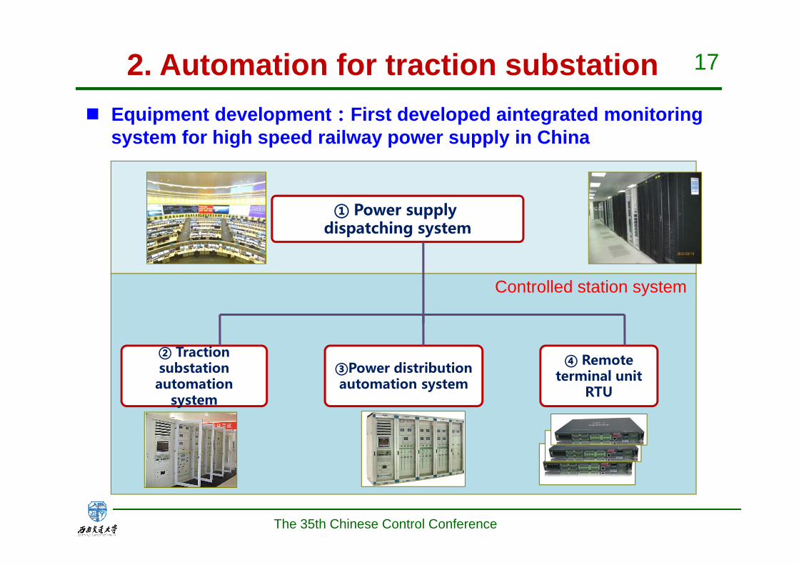
17
① Power supply dispatching system
④ Remote terminal unit
RTU
② Traction substation automation
system
③Power distribution automation system
Controlled station system
Equipment development:First developed aintegrated monitoring system for high speed railway power supply in China
2. Automation for traction substation
The 35th Chinese Control Conference

18
Power supply dispatching system
Dispatching
station
Ji'nan Rail Bureau
Guangzhou Railway Group
BeijingRail Bureau
Shenyang Rail Bureau
武汉Harbin Rail Bureau
Shanghai Rail Bureau
Wuhan Rail Bureau
Application
software
Cloud comput
ing platfor
mZhengzhou Rail Bureau
2. Automation for traction substation
The 35th Chinese Control Conference

19
Automatic traction substation system: 17 devices
2. Automation for traction substation
The 35th Chinese Control Conference

20
Electric substation automation system(16devices contained)
2. Automation for traction substation
The 35th Chinese Control Conference

21
Developed 5 categories of RTU
GM7-DGM7-CGM7-BGM7-AGM7-OPU
2. Automation for traction substation
The 35th Chinese Control Conference

22
Application Promotion in CRH
2. Automation for traction substation
The 35th Chinese Control Conference

23
Detection and Diagnosis of Pantograph - Catenary SystemPart III
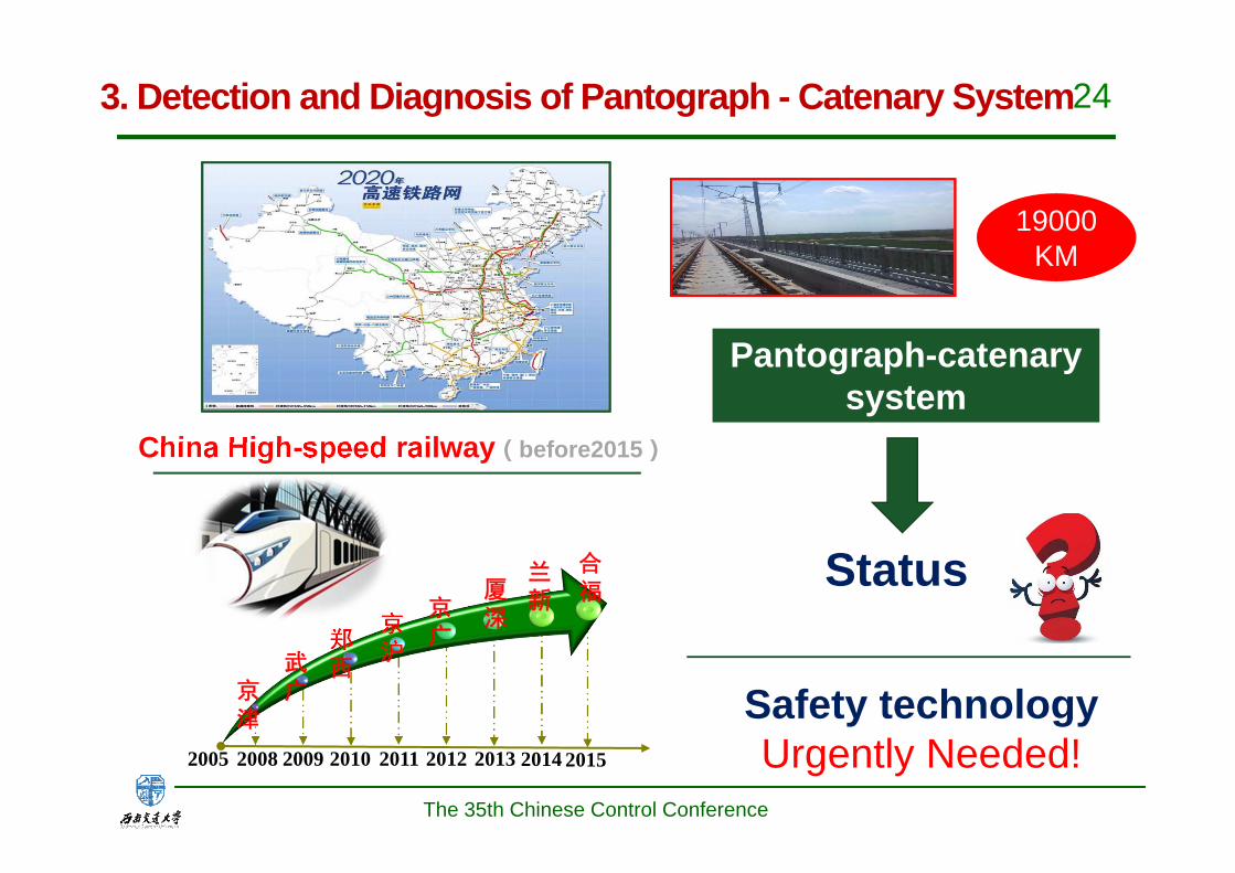
243. Detection and Diagnosis of Pantograph - Catenary System
19000KM
Status
Safety technologyUrgently Needed!2005 2009 2010 20112008 2012 2013 2014 2015
兰新厦
深京广
京沪
郑西武
广京津
合福
China High-speed railway(before2015)
Pantograph-catenary system
The 35th Chinese Control Conference
25
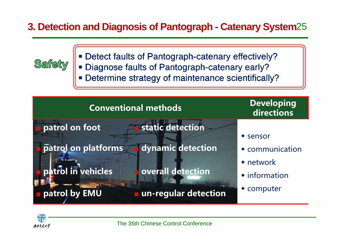
■ Detect faults of Pantograph-catenary effectively?■ Diagnose faults of Pantograph-catenary early?■ Determine strategy of maintenance scientifically?
■ Detect faults of Pantograph-catenary effectively?■ Diagnose faults of Pantograph-catenary early?■ Determine strategy of maintenance scientifically?
Conventional methods Developing directions
■ patrol on foot ■ static detection◆ sensor
◆ communication
◆ network
◆ information
◆ computer
■ patrol on platforms ■ dynamic detection
■ patrol in vehicles ■ overall detection
■ patrol by EMU ■ un-regular detection
The 35th Chinese Control Conference
3. Detection and Diagnosis of Pantograph - Catenary System

26
1C 2C 3C
4C 5C 6C
Comprehensive data center
1C: Comprehensive pantograph and catenary monitor device2C: Catenary-checking video monitor device3C: Catenary-checking online monitor device4C: High-precision catenary-checking monitor device5C: Pantograph video checking device6C: Ground monitor device for catenary and power supply equipmentData center
6C
Hierarchical and distributed system
The 35th Chinese Control Conference
3. Detection and Diagnosis of Pantograph - Catenary System
27
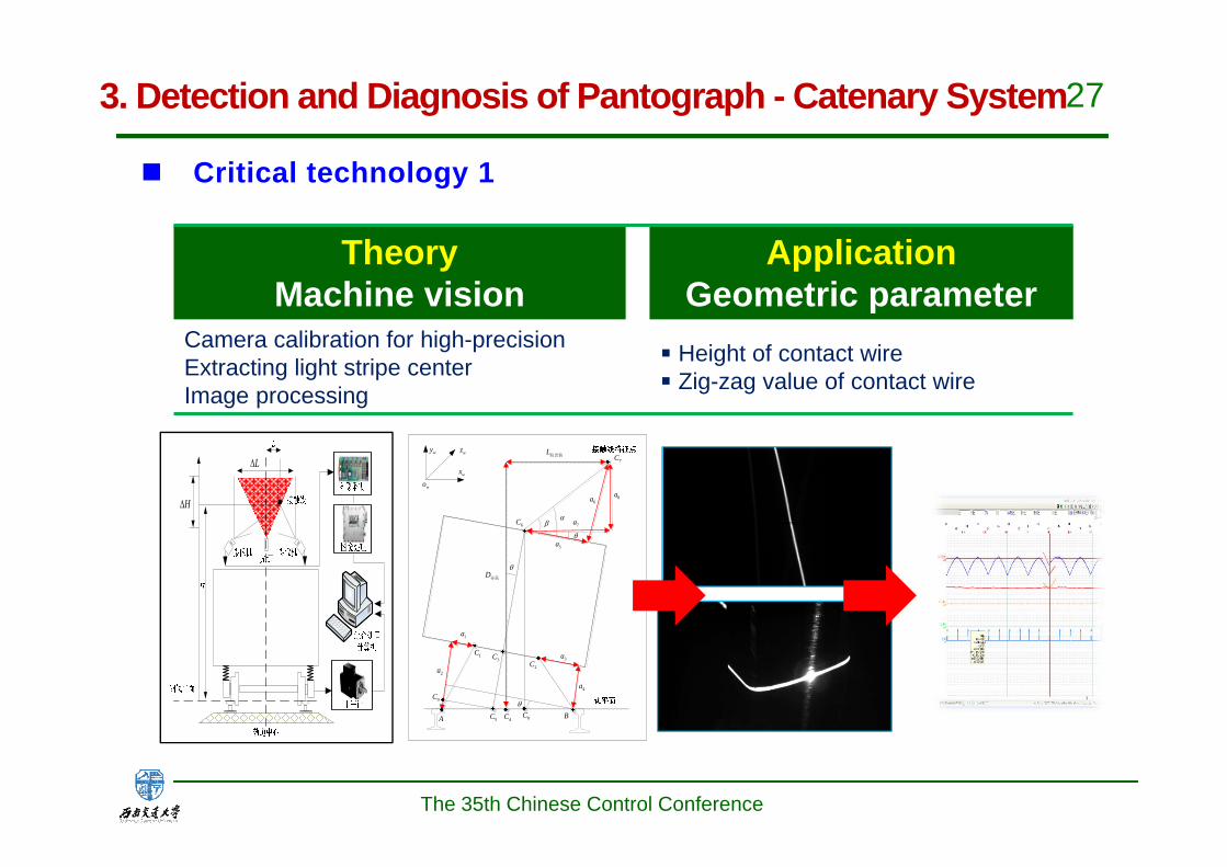
TheoryMachine vision
ApplicationGeometric parameter
Camera calibration for high-precisionExtracting light stripe centerImage processing
■ Height of contact wire■ Zig-zag value of contact wire
H
L
A B
1C
1a
2a3a
4a
5a
6a
7a
8a
4C
7C
5C
6C
L拉出值
D导高
2C3C
wx
wy
wo
wz
8C
9C
Critical technology 1
The 35th Chinese Control Conference
3. Detection and Diagnosis of Pantograph - Catenary System
28
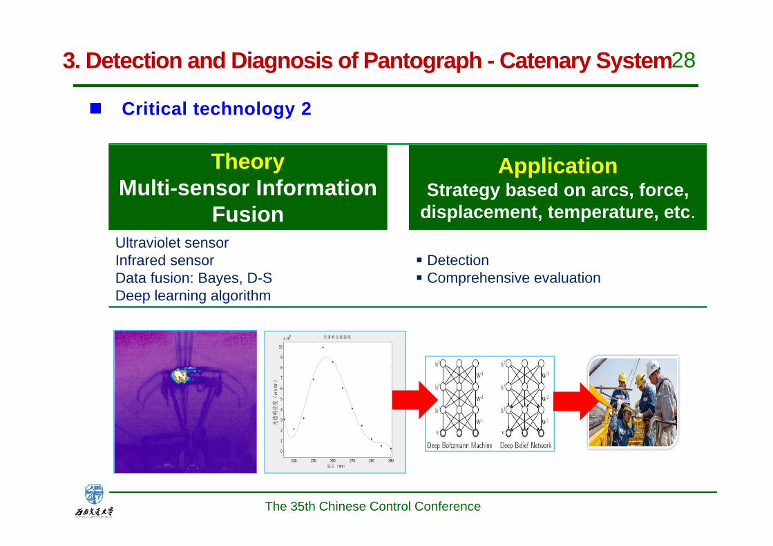
TheoryMulti-sensor Information
Fusion
ApplicationStrategy based on arcs, force,
displacement, temperature, etc.Ultraviolet sensor Infrared sensorData fusion: Bayes, D-SDeep learning algorithm
■ Detection■ Comprehensive evaluation
240 250 260 270 280 290
0
1
2
3
4
5
6
7
8
9
10
x 108
波长(nm)
光谱
响应
度(
mV
/W)
光 谱响应度曲线
Critical technology 2
The 35th Chinese Control Conference
3. Detection and Diagnosis of Pantograph - Catenary System
29
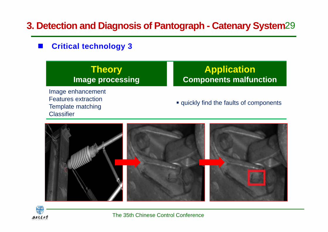
TheoryImage processing
ApplicationComponents malfunction
Image enhancementFeatures extractionTemplate matchingClassifier
■ quickly find the faults of components
Critical technology 3
The 35th Chinese Control Conference
3. Detection and Diagnosis of Pantograph - Catenary System

30
TheoryBig data and cloud computing
Applicationmanagement
Prognosis and health managementVirtualization Technology Distributed parallel architecture
Centralized analysis, monitor, management
Critical technology 4
The 35th Chinese Control Conference
3. Detection and Diagnosis of Pantograph - Catenary System

31
Definition
1CFixed detection device is installed on high speed comprehensivetrain. With the operation of comprehensive train,the detectionresults which include security and geometric parameters are usedto guide the repairs of the catenary.
ObjectiveThe target of detection is that making clear of the statement of thecatenary-pantograph, including the geometric parameters ofcatenary, wear, arcs, etc.
Drafted by SWJTUPromulgated by the Ministry of Railways
The 35th Chinese Control Conference
3. Detection and Diagnosis of Pantograph - Catenary System

32
Definition
2CPortable video device for detecting the state of catenary intemporary installation, to carry on statistics and analysis tothe status of catenary by image and guide the maintenance ofcatenary condition.
ObjectiveDetection target is the significant changes of catenarytechnology status , such as nest, tree damage, contactsuspension changes etc., recorded by video.
Drafted by SWJTUPromulgated by the Ministry of Railways
Dropper missed
The 35th Chinese Control Conference
3. Detection and Diagnosis of Pantograph - Catenary System

33
Definition
3CUnder condition of usual running, the device installed on the top ofEMU monitors the state of catenary and pantograph, achieve fullcoverage and dynamic detection.
ObjectiveTarget detection for dynamic geometric parameters includingheight, zigzag value, the distance between the two lines,pantograph catenary arc (arc rate, duration and arc energy, arcnumber etc.) and temperature of contact suspension etc.
Drafted by SWJTUPromulgated by the Ministry of Railways
0 2 4 6 8 10 12 14 16
x 104
0
100
200
300
400
时间(单位ms)
紫外燃弧能量(单位
mJ)
匀速340Km/h
0 2 4 6 8 10 12 14 16
x 104
0
100
200
300
400
紫外燃弧能量(单位
mJ)
匀速330Km/h
The 35th Chinese Control Conference
3. Detection and Diagnosis of Pantograph - Catenary System
34
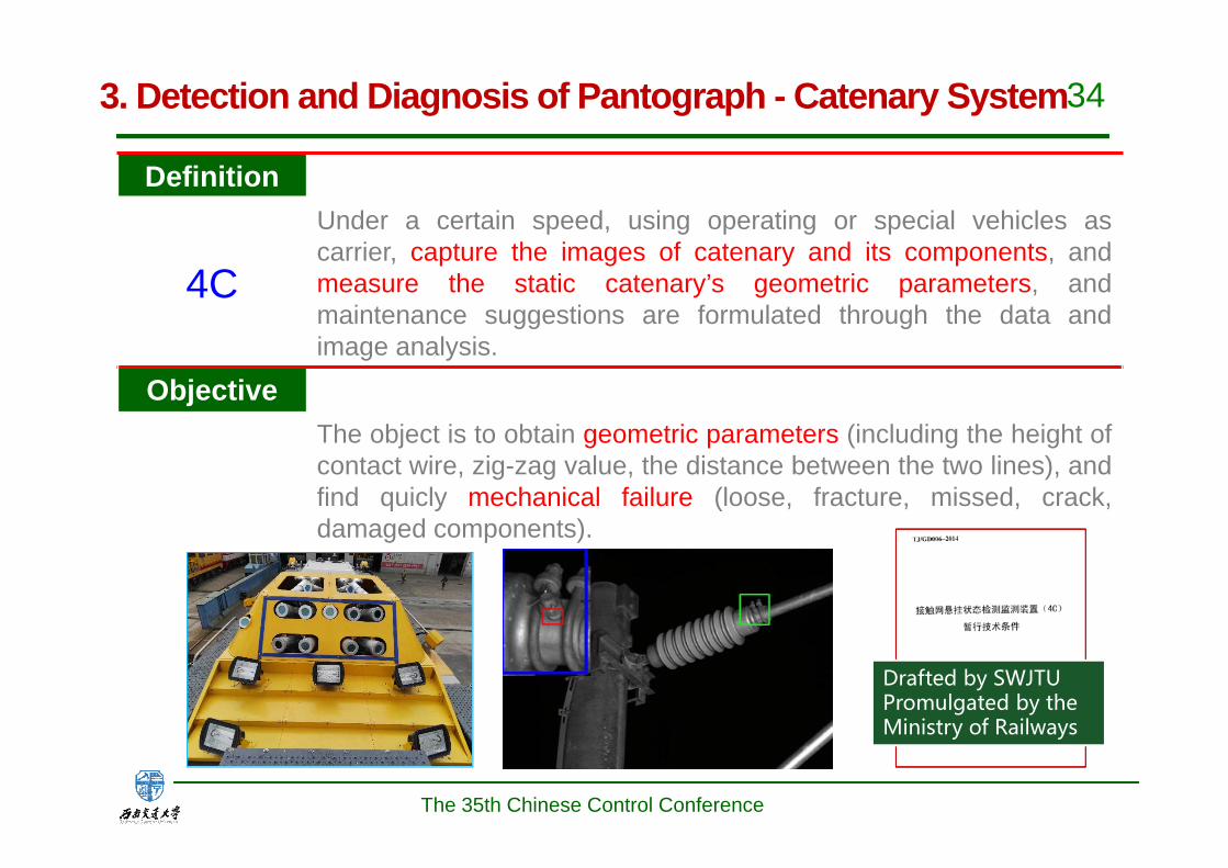
Definition
4C
Under a certain speed, using operating or special vehicles ascarrier, capture the images of catenary and its components, andmeasure the static catenary’s geometric parameters, andmaintenance suggestions are formulated through the data andimage analysis.
ObjectiveThe object is to obtain geometric parameters (including the height ofcontact wire, zig-zag value, the distance between the two lines), andfind quicly mechanical failure (loose, fracture, missed, crack,damaged components).
Drafted by SWJTUPromulgated by the Ministry of Railways
The 35th Chinese Control Conference
3. Detection and Diagnosis of Pantograph - Catenary System
35
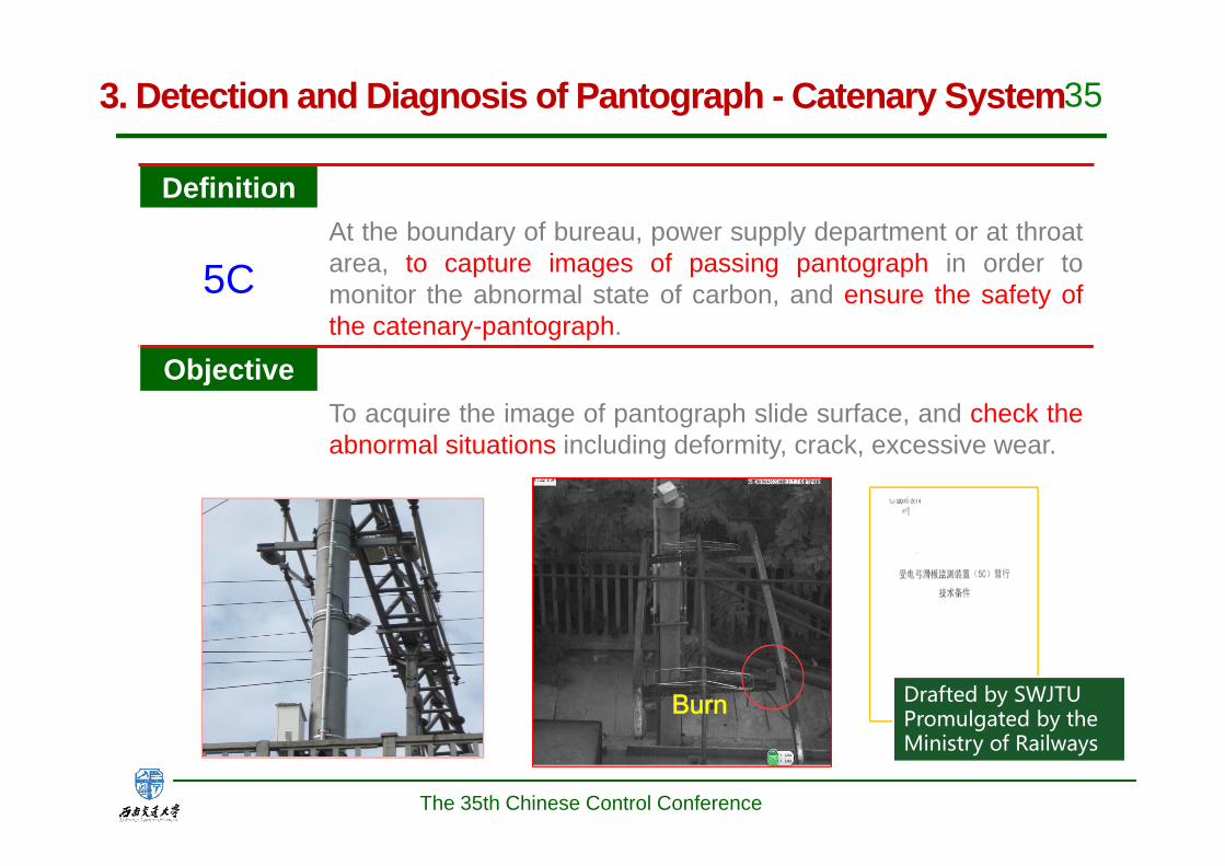
Definition
5CAt the boundary of bureau, power supply department or at throatarea, to capture images of passing pantograph in order tomonitor the abnormal state of carbon, and ensure the safety ofthe catenary-pantograph.
ObjectiveTo acquire the image of pantograph slide surface, and check theabnormal situations including deformity, crack, excessive wear.
Drafted by SWJTUPromulgated by the Ministry of Railways
Burn
The 35th Chinese Control Conference
3. Detection and Diagnosis of Pantograph - Catenary System

36
Definition
6CBe set up in the special section of catenary and the tractionsubstation, and to carry out the real-time monitoring of the singleparameter of catenary or the power supply equipment in order toguide the maintenance.
ObjectiveThe monitoring objects include the tension force, vibration, uplift,temperature, compensation displacement of catenary and theinsulation of the power supply equipment, cable joint temperature.
Drafted by SWJTUPromulgated by the Ministry of Railways
0 50 100 150 200 250 300 350 400-50
0
50复合13号杆绝缘子
采样点/个
泄漏
电流
/mA
The 35th Chinese Control Conference
3. Detection and Diagnosis of Pantograph - Catenary System

37
China Railway CorporationData center
Railway BureauData center
Power supply departmentData center
The 35th Chinese Control Conference
3. Detection and Diagnosis of Pantograph - Catenary System
38
Prognostics and Health Management(PHM) for traction substationPart IV
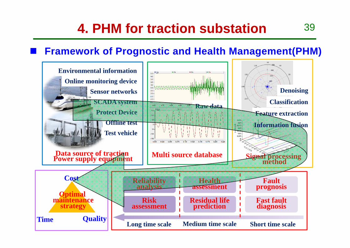
39
Online monitoring device
Offline test
Sensor networksSCADA system
Test vehicle
Protect Device
Environmental information
Multi source databaseData source of traction Power supply equipment Signal processing
method
Fault prognosis
Fast fault diagnosis
Health assessment
Reliability analysis
Short time scaleMedium time scaleLong time scale
Risk assessment
Residual life prediction
Cost
Time Quality
Optimalmaintenance
strategy
Raw data
Denoising
Classification
Feature extraction
Framework of Prognostic and Health Management(PHM)
Information fusion
4. PHM for traction substation

40
Multi-source and multi-scale data of PHM
4. PHM for traction substation
The 35th Chinese Control Conference
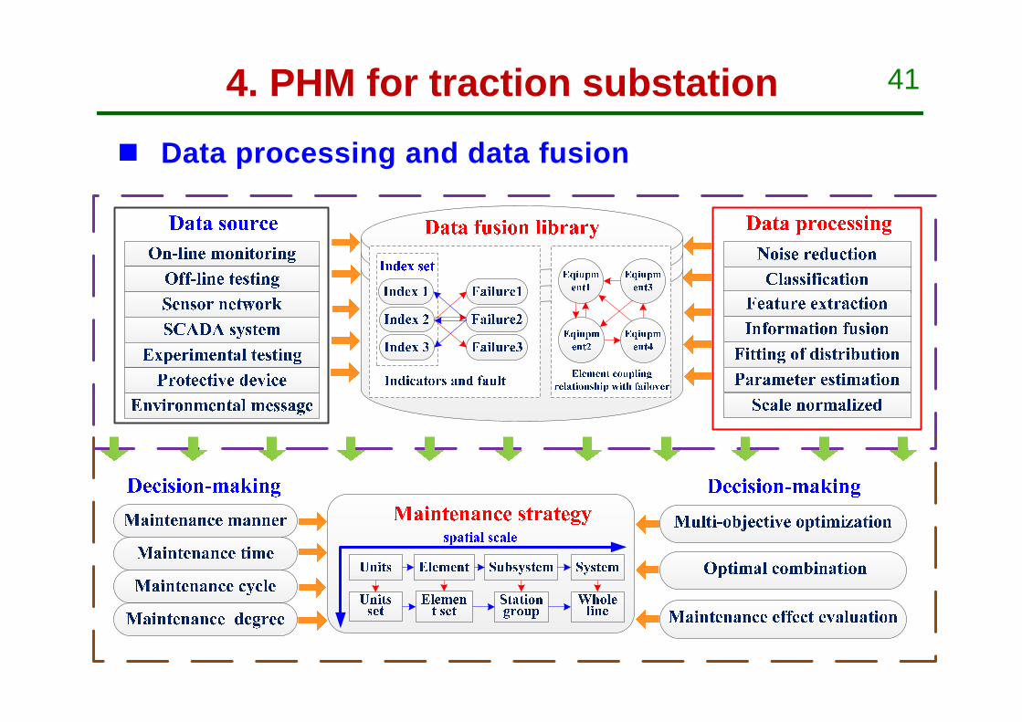
41
Data processing and data fusion
4. PHM for traction substation
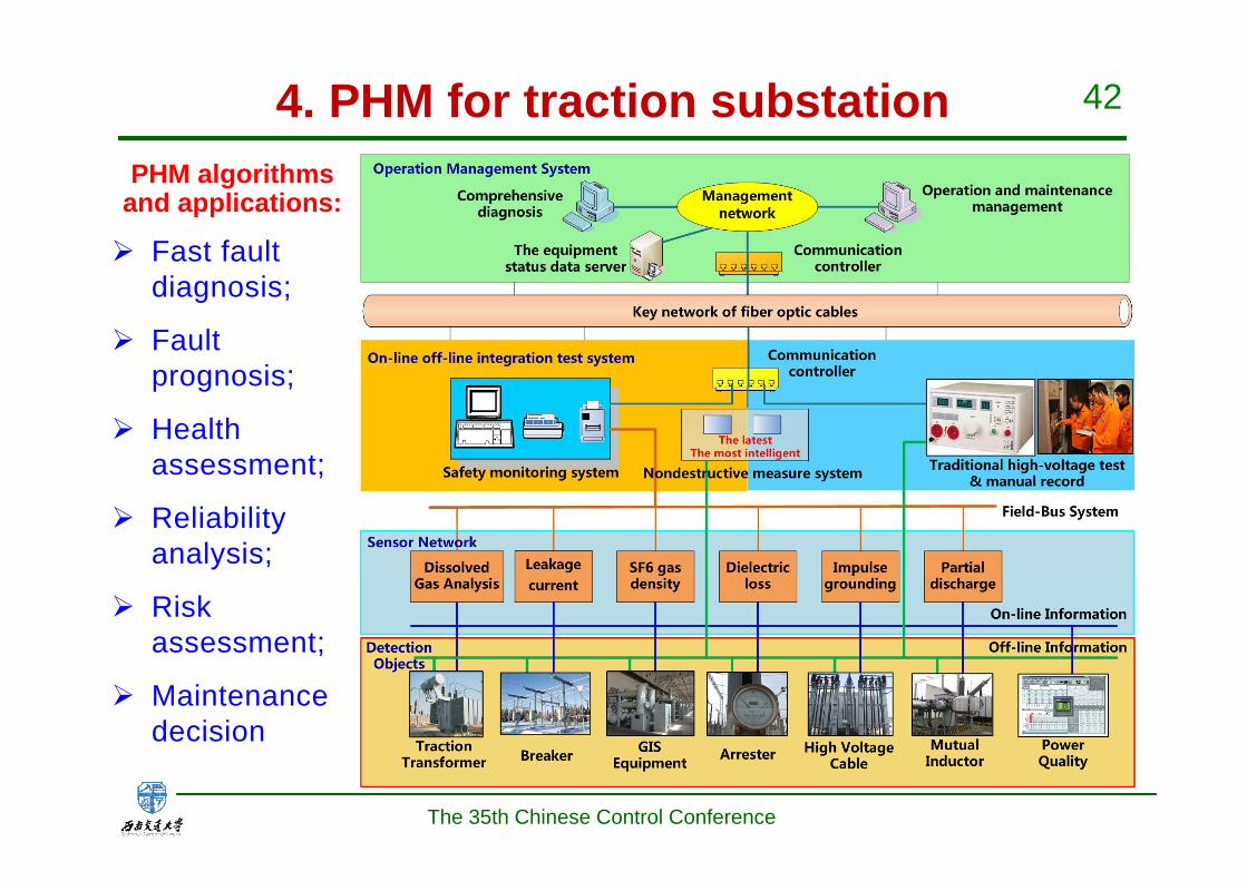
42
Fast fault diagnosis;
Fault prognosis;
Health assessment;
Reliability analysis;
Risk assessment;
Maintenance decision
PHM algorithms and applications:
4. PHM for traction substation
The 35th Chinese Control Conference
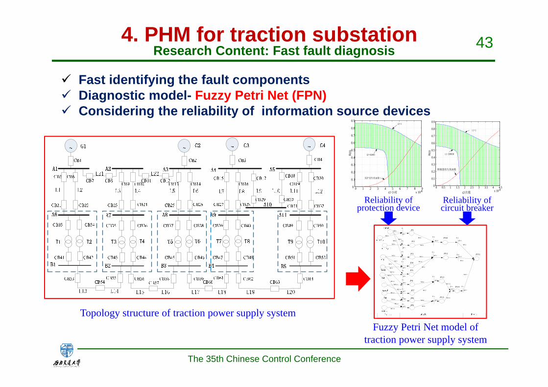
43
Fast identifying the fault components Diagnostic model- Fuzzy Petri Net (FPN) Considering the reliability of information source devices
Topology structure of traction power supply system
Research Content: Fast fault diagnosis
11w
12w
13w14w
16w
17w
1t
2t
3t
1P
2P
3P
4t
5t
8t
9t
21w
22w
23w
24w
31w
32w
10P
11P 1PT
1
2
3
4
5
6
7
4P
5P
25w
15t
16t
8
9
6t
7t
6P
7P
10t
12P
10
26w
27w
33w
8P
9P
11t
17t
12t
11
12
13
13t
15w
18w
19w
110w
111w
112w113w
114w
115w
116w
117w
118w
28w
29w
210w
211w
14t14
15
16
17
13P
14P
Fuzzy Petri Net model of traction power supply system
0 1 2 3 4 5 6 7 8 9x 10⁴
0
0.1
0.2
0.3
0.4
0.5
0.6
0.7
0.8
0.9
t1/小时
R(t
)
t2=1
t2=45000
保护的失效函数
0 0.5 1 1.5 2 2.5 3 3.5 4 4.5x 10⁴
0
0.1
0.2
0.3
0.4
0.5
0.6
0.7
0.8
0.9
t2/次数
R(t
)
t1=1
t1=90000
断路器的失效函数
Reliability of protection device
Reliability of circuit breaker
4. PHM for traction substation
The 35th Chinese Control Conference
44
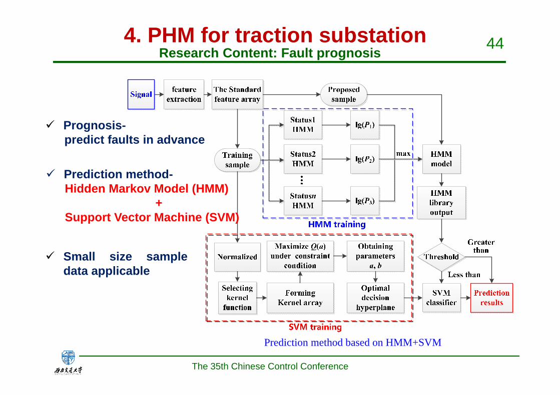
Prognosis-predict faults in advance
Prediction method based on HMM+SVM
Research Content: Fault prognosis
Small size sampledata applicable
Prediction method-Hidden Markov Model (HMM)
+ Support Vector Machine (SVM)
4. PHM for traction substation
The 35th Chinese Control Conference

45
Health value and its significance
Research Content: Health assessment
1-0.9600 0.9599-0.9 0.8999-0.8 0.7999-0.6 0.5999-0
Health Subhealth Slightly morbid Medium morbid Serious morbid
Safe Deteriorating
No faultEarly latent hazard Late latent hazard Functional fault
Fault
Health value
Health status
Service Performance
Fault evolution
Failure
Hidden fault
Health value reflect performance and fault situation ofequipment and system
Assessment model- Analytic Hierarchy Process (AHP): fromequipment layer to system layer
Algorithm- Fuzzy statistics: eliminate subjective uncertainty
Health assessment model and algorithm
4. PHM for traction substation
The 35th Chinese Control Conference
46
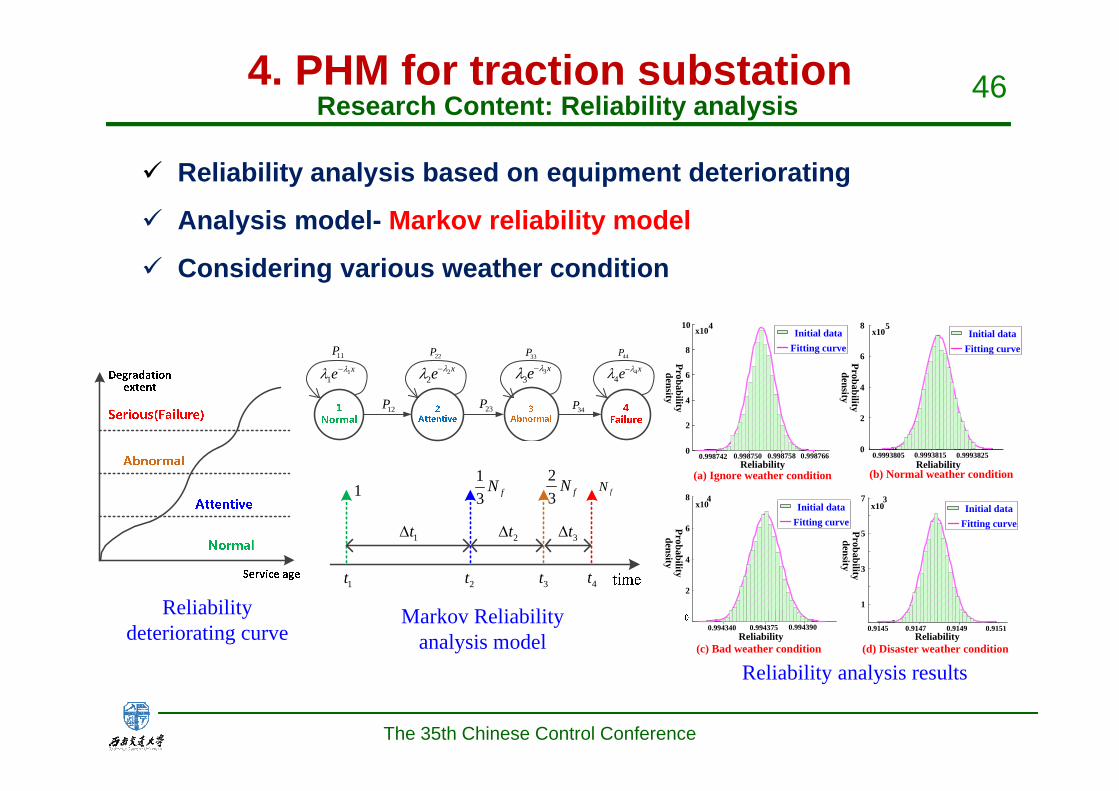
Reliability deteriorating curve
Research Content: Reliability analysis
Reliability analysis based on equipment deteriorating
Analysis model- Markov reliability model
Considering various weather condition
Reliability analysis results
12P
11P 22P
23P
33P
34P
44P
11
xe 22
xe 33
xe 44
xe
1t 2t 3t 4t
13 fN fN
23 fN1
1t 2t 3t
(a) Ignore weather condition
Initial dataFitting curve
0
2
4
6
8
10 x104x10
5
0
2
4
6
8
0.9993805 0.9993815 0.99938250.998750 0.9987660.9987580.998742
x104
0.994340 0.994375 0.994390
2
4
6
8
0.9145 0.9147 0.9149 0.9151
1
3
5
7x10
3
Probability density
Reliability
Initial dataFitting curve
Reliability(b) Normal weather condition
Probability density
Initial dataFitting curve
Reliability
Probability density
(c) Bad weather condition
Initial dataFitting curve
Reliability
Probability density
(d) Disaster weather condition
Markov Reliability analysis model
4. PHM for traction substation
The 35th Chinese Control Conference

47
Traction power supply system lightning risk area illustration
Research Content: Risk assessment
Lightning risk assessment for traction substation andoverhead catenary
Direct lightning risk + Induced lightning risk
Primary equipment risk + Secondary equipment risk
变电所建筑物
H 1:3
3H
W
L
(×10-3)
0.00.51.01.52.02.53.03.54.04.55.0
Traction substation Overhead CatenaryPrimary equipmentrisk by Direct Lightning strike
Secondary equipmentrisk by Direct Lightning strike
Equipment risk by induced lightning Total lightning risk
Ligh
tnin
g ris
kva
lue
lower limit
Upper limit
Risk interval
Lightning risk assessment results
4. PHM for traction substation
The 35th Chinese Control Conference

48Research Content: Maintenance decision
Maintenance strategy
Cost
Health (Reliability)
Inspection cost
Downtime lossMaintenance cost
Condition-based maintenance curvex
y
z
M
M1
M2
Health
Reliability Safety
Maintenance EconomyNo action?postponed?Prioritized?ASAP?Immediate?
Maintenance time decision
Breakdown maintenance (BM)?Preventive maintenance (PM)?Hazard detection (HD)?Condition based maintenance (CBM)?
Maintenance mode decision
Period of PMFrequency of Manual inspectionInspection frequency of potential hazardInspection frequency of hidden fault
Maintenance period decision
No maintenance?Minimum maintenance?Imperfect maintenance?Perfect maintenance?
Maintenance extent decision
Various maintenance decision parameters
Five maintenance properties
Multi-objective optimization method
Five maintenance properties
Multi-objective optimization
Example of maintenance decision parameters
4. PHM for traction substation
The 35th Chinese Control Conference

49PHM and data management software
Integrated informationdatabase
Visualization module
Data analysis and process module
Maintenance decision module
Raw data
Customized data
Mutual support
Report forms
Generate & Print
Software input module
Raw dataEquipment importance evaluation module
Health assessment module
Data management module
Generate history data
Maintenance mode decision
Maintenance period decision
Maintenance optimization
Fault prognosis module
Fast fault diagnosis module
Software structure frame diagram
4. PHM for traction substation
The 35th Chinese Control Conference

50
Main interface of health assessment
Software interface(1) Health assessment module
Equipment configuration information
Health assessment results
Equipment health trend
PHM and data management software4. PHM for traction substation
The 35th Chinese Control Conference

51
Software interface(2) Fault prognosis module
Equipment fault degradation trend
Main interface of fault prognosis Prognosis and condition monitoring results
PHM and data management software4. PHM for traction substation
The 35th Chinese Control Conference

52
Software interface(3) Fast fault diagnosis module
Fast fault diagnosis results
Main interface of fast fault diagnosis Recommended maintenance strategy
PHM and data management software4. PHM for traction substation
The 35th Chinese Control Conference
53
The 35th Chinese Control Conference
Conclusion
School of Electrical engineering in Southwest Jiaotong
Univ. has achieved rich results in protective control, power
supply monitoring and dispatching, pantograph-catenary
system and PHM for high-speed railways.
Simultaneously, the control theory and electronics
technologies are used in the state-of-the-art technologies in
our school, such as co-phase supply system, Maglev
system, wireless traction power system.
Thanks for any
suggestions!
The 35th Chinese Control Conference
Related Documents