5 5 Wireline Services C O N T E N T S 1 SURFACE EQUIPMENT FOR WIRELINE 1.1 Wireline 1.2 Monitoring Equipment 1.3 Alignment Pulley System 1.4 Tool String Insertion Under Well Pressure 2 WIRELINE TOOL STRING 2.1 Stem 2.2 Jars 2.3 Knuckle Joint 3 WIRELINE OPERATING TOOLS 3.1 Gauge Cutter 3.2 Swage 3.3 Impression Tool 3.4 Wireline Spear 3.5 Blind Box 3.6 Wireline Bailer 3.7 Tubing Perforator 3.8 Positioning Tools 3.9 Running Tools 3.10 Pulling Tools SUMMARY

Welcome message from author
This document is posted to help you gain knowledge. Please leave a comment to let me know what you think about it! Share it to your friends and learn new things together.
Transcript

55Wireline Services
C O N T E N T S
1 SURFACE EQUIPMENT FOR WIRELINE1.1 Wireline1.2 Monitoring Equipment1.3 Alignment Pulley System1.4 Tool String Insertion Under Well Pressure
2 WIRELINE TOOL STRING2.1 Stem2.2 Jars2.3 Knuckle Joint
3 WIRELINE OPERATING TOOLS3.1 Gauge Cutter3.2 Swage3.3 Impression Tool3.4 Wireline Spear3.5 Blind Box3.6 Wireline Bailer3.7 Tubing Perforator3.8 Positioning Tools3.9 Running Tools3.10 Pulling Tools
SUMMARY

1
2
LEARNING OBJECTIVES:
Having worked through this chapter the Student will be able to:
• Describe the mechanisms of a slick wireline operation.
• List and describe the commonly used downhole wireline equipment and tools.
• List and describe the surface wireline equipment requirements; lubricator; BOP;stuffing box.
• Describe well pressure control and safety issues associated with wireline.
• State the limitations on successful wireline operation imposed by depth, holeangle and dog leg severity
55
Department of Petroleum Engineering, Heriot-Watt University 3
Wireline Services
INTRODUCTION
The majority of well completions utilise one or more of the technique of downholewireline. Wireline can be used to accomplish the following:-
(1) the installation of completion equipment prior to running the production tubinge.g. a packer and optionally a tailpipe assembly.
(2) the installation (and retrieval) of equipment within the tubing string e.g. valves,pressure gauges, etc
(3) the operation of downhole tubular equipment to either divert or shut off fluid flow
(4) the removal of materials which can build up in the tubing string such as wax or sand.
In short, wireline can be used to accomplish a variety of tasks both in the wellbore andthe completion string. These tasks can either be to operate equipment or eliminate thenecessity to pull the completion string to replace certain key components when amalfunction occurs.
The principle of downhole wireline is that of lowering a tool to perform a specificfunction, as part of a tool string on either a single strand wire or a braided cable, downthe inside of the tubing string. Manipulation of the tool string either by raising orlowering will impart a jarring effect on the tool and hence activate the setting orretrieval mechanism.
Given the relative simplicity of wireline, in many cases it will be a quicker and moreeconomical alternative to pulling the tubing string to replace faulty equipment.However, since wireline must be capable of being used deep in the well, the operatoris physically very remote from the location at which the tool is to operate. Thisremoteness, when coupled with the uncertainty of cable stretch especially in deviatedwells and the small scale of the tools, make wireline a technique which requires highlyskilled personnel to ensure its effectiveness. However, when wireline techniquescan be successfully employed and are incorporated into the completion string design,they provide a significant degree of flexibility in terms of well operations andservicing capability.
The capabilities offered by wireline are numerous and a few are identifiedbelow:-
(1) Isolation of the formation by setting a plug in a wireline nipple in the tubing string.
(2) Operation of sliding side doors to allow annulus communication or to isolatezones in multi-zone selective completions.
(3) Installation and retrieval of subsurface safety valves (S.S.S.V.), downholechokes and regulators.

1
4
(4) The ability to run in, land off and retrieve downhole pressure and temperature gauges.
(5) The installation and retrieval of valves in side pocket mandrel systems.
(6) Removal of wax from the inside walls of tubing and tubular component by scraping.
(7) Removal of sand and produced solids from the wellbore sump or above a restriction.
(8) Installation of through tubing bridge plugs to isolate zones or in well abandonmentoperations.
(9) Using electrical conductor cable, packers can be run with or without a tail pipeand set in the wellbore.
However, perhaps the greatest asset of downhole wireline is the ability to conductthese operations on a live well i.e. one where communication between the reservoirand the wellbore and tubing head pressure may exist.
1 SURFACE EQUIPMENT FOR WIRELINE
To enable downhole wireline operations to be performed, equipment must beprovided at surface to allow the following:-
(a) the lowering and retrieval of the tool string to the work location.
(b) monitoring of tool position and cable tension.
(c) handling and alignment pulleys so that the tool string can be positionedvertically above the well for lowering through the Xmas tree and into the tubing string.
(d) the ability to insert the tool string into the live well and to prevent pressure from escaping.
(e) a blowout preventor which will seal off the annulus around the cable and ifrequired cut the wireline.
The components of a conventional wireline system is shown in figure 1.

55
Department of Petroleum Engineering, Heriot-Watt University 5
Wireline Services
Stuffing Box
Lubricator
Lifting Clamp
Bleed-Off Valve
Blow-Out Preventor
Tree Connection
Hay Pulley
Weight Indicator
Xmas Tree
Gin Pole
1.1 WirelineConventional wireline or “slick wireline” as it is frequently referred to, utilises a singlestrand high tensile wire. The wire is normally made from high tensile steel so that theratio of breaking strength (in lbs) to wire diameter (inches) can be maximised. Thiswill normally allow the minimum diameter of cable to be used, which is desirablefor the following reasons:-
(1) it reduces the total weight of the wireline itself.
(2) it is more pliable and can be bent over smaller diameter sheaves and drum reels.
(3) it minimises the upwards pressure force on the tool string due to the differencein plain end areas at the top and bottom of the tool string.
A variety of wireline sizes are available and some are shown in table 1. Normally 50%of the maximum breaking strength is used as a working limit. In some environmentswhere H5S may be present, the high tensile steel will be very susceptible tohydrogen embrittlement and it may be necessary to add an additional safetyfactor, limit the period of use, or alternatively use low tensile steels with a lowerbreaking strength.
In cases where a higher breaking strength is required it is possible to usebraided cables which are available in sizes of 1/8", 9/64", 3/16" and 1/4". However,it is more difficult to create a continuously effective high pressure seal arounda braided cable because of its construction.
Figure 1
Surface Equipment
Requirements for Wireline
Operations

1
6
Single strand wireline is available in a range of lengths: 10000, 12000, 15000,18000, 20000 and 25000 ft.
The wireline is normally wound onto a reel on a self contained skid which hasits own power supply for drum rotation and creating cable tension.
Wire Line Type
Bright Steel
(Improved Plow Steel/Carbon Steel)
API Wire
Monitor AA
(Extra Improved Plow
Steel/Improved
Carbon Steel)
AISI 304
Super Tensile
AISI 304
Ultra Tensile
AISI 316
Super Tensile
8-18-2
Super Tensile
Size (in)
.082
.092
.105
.082
.0932-
.105
.108
.082
.092
.105
.082
.092
.105
.082
.092
.105
.108
.082
.092
.105
.108
Tensile (Psi)
234.000
232.000
237.000
276.000
275.000
280.00
280.000
240.000
240.000
240.000
290.000
210.000
210.000
210.000
210.000
190.000
190.000
190.000
190.000
Breaking StrengthMin. (lbs)
1239
1547
2050
1460
1830
2420
2561
1280
1582
2070
2100
1110
1390
1810
1920
1000
1280
1645
1740
Torsions in 8 in.
26
23
20
17
3
3
3
3
3
3
3
3
3
Weight/100 ft. (lbs)
17.93
22.58
29.00
17.93
22.58
29.00
17.85
22.62
30.24
17.875
22.62
30.24
17.85
22.62
30.24
17.85
22.62
30.24Table 1
Wireline Data

55
Department of Petroleum Engineering, Heriot-Watt University 7
Wireline Services
1.2 Monitoring EquipmentGiven the remoteness of the operator from the tool string suspended on thewireline downhole, the important parameters during the operation will be thetool string location, or depth in the well, and the tension on the cable.
The length of cable used and accordingly the depth of the tool string withreference to a datum point e.g. the tubing hanger in the wellhead, is measuredby allowing the cable to be held without slippage against a hardened wheel orodometer.
The cable tension is continuously monitored to ensure that the breakingstrength of the cable is not exceeded. The cable tension will also be reducedas tool string is lowered through restriction in the tubing string due to fluidpressure and hence to a limited extent cable tension can also be used as anapproximate indication of tool position.
1.3 Alignment pulley systemIn view of the length and rigidity of the tool string it is necessary for the cableto be passed across a double sheave system which first of all changes theorientation of the cable from the horizontal to the vertical plane and secondlychanges the orientation by 180° to lower the tool string into the well as shownin fig. 1. The pulleys are selected to provide the minimum bending stress onthe wireline during use.
1.4 Tool string insertion under well pressureTo allow the tool string to be inserted into a live well, it is necessary to attachto the Xmas tree, above the swab valve, a pressure tube known as a lubricatorinto which the tool string can be inserted and lowered down the well throughthe Xmas tree. Once the lubricator has been aligned vertically above the Xmastree and coupled to it using a quick release, high pressure coupling, the swabvalve can be opened to allow the well to pressurise the lubricator. To preventwell pressure escaping from the top of the lubricator above where the wirelineis installed, the wire must be passed through a wireline stuffing box. Theassembly is depicted in figure 2. Attached to the top of the stuffing box unitis the upper sheave which redirects the wireline through 180°. The wirelinepasses through the top of the stuffing box, through a series of washer typepacking units and culminates in a knot within a rope socket inside thelubricator (Fig. 3). The rope socket has a female threaded section at its baseto which the tool string can be attached.

1
8
Sheave Guard
Sheave Wheel
Oil Reservoir
Gland Nut
Top Gland
Packing
Bottom Gland
Internal B.O.P.
Internal B.O.P. Retainer
Swivel Bearings
Pressure Relief Valve
Quick Union
The length of the lubricator can be varied since the lubricator can be obtainedin sections which can be screwed together to give the required length. Thelubricator is available for working pressures up to 15000 psi and diametersranging from 25/8" to 51/8" for standard or sour (H2S) service.
Figure 2
Wireline Lubricator
Stuffing Box
Figure 3
Wireline Rope Socket

55
Department of Petroleum Engineering, Heriot-Watt University 9
Wireline Services
At the base of the lubricator just above the point of attachment to the Xmas tree,it is necessary to instal a wireline B.O.P. valve. This valve can either bemanually or hydraulically activated and can either be a single or dual ram unit,Figures 5 and 6 respectively. These rams are designed to close off around thewireline and retain full well pressure below the ram.
After closure, well pressure above and below the ram must be equalisedthrough the equalising ports shown in Figures 4 and 5. Further, a vent valveon the lubricator allows the depressurisation to take place, for example, whenthe tool string has been recovered into the lubricator and the swab valve on theXmas tree closed.
Normally, the packing in the stuffing box is compressed upwards and inwardsaround the wireline by the well pressure. However, in some cases a hydraulicpacking system is utilised whereby grease is injected into a flow tube immediatelybeneath the stuffing box. The hydraulic pressure applied to the high viscositygrease regulates the efficiency of pressure sealing in the stuffing box.
Prior to running any tools into the well, the lubricator and wireline B.O.P.valves must be tested to the required pressure.
Ram AssemblyLeft Hand
Ram AssemblyRight Hand
Pin EndO-Ring
Equalising ValveAssembly
Figure 4
Single Ram Hydraulic
Wireline Valve

1
10
Ram AssemblyLeft Hand
Ram AssemblyRight Hand
Equalising ValveAssembly
Pin End O-Ring
2 WIRELINE TOOL STRING
The tool string is attached to the rope socket at the end of the wireline. Besidesconnecting to the wireline, the tool string must also provide:-
(1) the ability to provide weight so that the wireline is held in tension and can berun into the well at an acceptable speed.
(2) the activity to accommodate fairly rapid changes in inclination within thetubing string particularly in deviated wellbores.
(3) the ability to provide a jolt upwards or downwards on the work tool by upwardsof downwards jarring.
(4) the correct running or pulling tool to instal or retrieve the wireline componentwithin the tubing string. Alternatively an auxiliary function tool such as aparaffin cutter may be conveyed.
A schematic of a tool string is shown in Figure 6.
Figure 5
Dual Ram Hydraulic
Wireline Valve

55
Department of Petroleum Engineering, Heriot-Watt University 11
Wireline Services
RopeSocket
Stem
PowerJars
MechanicalJars
KnuckleJoint
2.1 StemWhen a wireline tool string is run into the well, there are two forces whichoppose the tool string:-
(1) the frictional force as the wireline is pulled downwards through the packingelements of the stuffing box.
(2) a differential force acting upwards on the tool string due to the difference in theplane end areas of the top and bottom of the tool string due to the diameter ofthe wireline itself. The force can be calculated as follows:
Maximum upwards force =
max. fluid pressure in the wellbore (psi) x π/4 d2
where d = nominal wireline outside diameter in inches.
Thus based upon the anticipated well pressure and the nominal diameter of thewireline, additional weight will be required to ensure tool string descent intothe well and this is provided by incorporating a length of stem bar in the tool
Figure 6
Schematic of Wireline Tool
String

1
12
string. This is only approximate as it neglects the effect of friction in thestuffing box packing.
The stem bar is available in a range of nominal diameters from 3/4" to 17/8"and in lengths of 2ft., 3ft. and 5ft. The stem bar is attached directly to the ropesocket using the thread connecting system (Fig. 7).
2.2 JarsSince the operation of all wireline equipment is affected by mechanical impact,it is essential that the tool string can deliver the weight of the stem bar as a joltor jar to the operating tool. This is accomplished by placing a set of jarsimmediately below the stem. Most frequently, mechanical jars, as depictedin Fig. 9, are employed and these can be used to create a jarring force in eitherthe upwards or downwards direction. The action is such that these jars aresometimes referred to as stroke jars.
Figure 7
Stem Bar

55
Department of Petroleum Engineering, Heriot-Watt University 13
Wireline Services
Figure 9
Hydraulic Jar (left)
Fgure 10
Accelerator (right)
Figure 8
Mechanical Jars
1
14
In addition, it is possible to run a set of hydraulic jars immediately above themechanical jars, but these only provide a jarring capability in the upwardsdirection. If hydraulic jars are used in shallow well operations an acceleratoris frequently added which helps to maintain a steady pull on the hydraulic jaras it starts to open, Fig. 10.
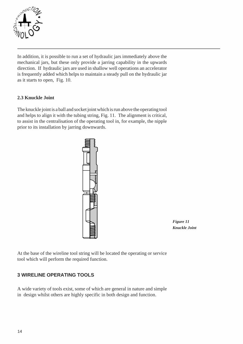
2.3 Knuckle Joint
The knuckle joint is a ball and socket joint which is run above the operating tooland helps to align it with the tubing string, Fig. 11. The alignment is critical,to assist in the centralisation of the operating tool in, for example, the nippleprior to its installation by jarring downwards.
At the base of the wireline tool string will be located the operating or servicetool which will perform the required function.
3 WIRELINE OPERATING TOOLS
A wide variety of tools exist, some of which are general in nature and simplein design whilst others are highly specific in both design and function.
Figure 11
Knuckle Joint

55
Department of Petroleum Engineering, Heriot-Watt University 15
Wireline Services
3.1 Gauge cutterPrior to conducting any specific wireline operation in the well it is goodpractice to run the tool string into the well with a gauge cutter on the end to theprescribed depth. This will determine:-
(1) if the tool string will have passage down the inside of the tubing.
(2) the top of individual landing nipples of specific sizes.
Gauge cutters are available for all tubing sizes up to 7" nominal diameter.
3.2 Swage
If a minor obstruction is encountered in the tubing, then a swage can be loweredon the tool string and used as a mash to open tubing or clear the obstruction.
Figure 12
Gauge Cutter
Figure 13
Swage

1
16
3.3 Impression toolAll wireline mandrels and tools are designed with a fishing neck on top, so thatif the wireline breaks, hopefully at the rope socket as intended, then a fishingoperating with an overshot should latch on to the tool and allow its retrievalfrom the well. However, it will be necessary, prior to commencing a fishingoperation, to establish the condition and position of any obstruction on the topof the fish. A lead impression block has a lead filled core at its base and whenlowered on to the fish will provide an imprint of the physical condition of thetop of the fish.
3.4 Wireline spearThe wireline in normally expected to break at the rope socket during normalfailure such that the wireline itself can be pulled from the hole. In the event thatthe wireline breaks at a different location, the wire may form a ‘birds nest’ inthe tubing which will need to be removed by a grapple known as a wirelinespear, Fig. 14.
Figure 14
Wireline Spear (left)

55
Department of Petroleum Engineering, Heriot-Watt University 17
Wireline Services
3.5 Blind boxIn operations where the tool string is required to jar down onto a fish orobstruction, a blind box can be used at the base of the tool string, Fig. 15.
3.6 Wireline bailerThe build up of solid deposits e.g. sand in the wellbore or perhaps thedeposition of solids on top of a tubular component such as a mandrel, maynecessitate the use of bailers. Particularly in the latter case it may be necessaryto remove the solids prior to gaining access to the pulling neck of the mandrel.
A bailer can be run on a wireline tool string. Two general types are available,the first is operated by jarring up and down on a piston bailer which acts to sucksand into the bailer. The other design known as a hydraulic bailer, comprisesa chamber at atmospheric pressure, a shear disc and non-return ball valve.Downwards jarring on the solids will shear the disc and the solids will besucked up into the low pressure chamber.
3.7 Tubing perforatorIn cases where the facility to circulate between the annulus and the tubing iseither non existent or inoperable, it is possible to run a tubing perforator on awireline tubing string. The tubing punch can be used in both standard andheavy weight tubings and is available in sizes from 11/4" nominal dia. to 5"nominal dia. Again the punch is activated by jarring.
Figure 15
Blind Box (right)

1
18
Slips
Shear Pin
Double TapeWedge
Safety Catch
Safety Shear
Punch
3.8 Positioning toolsThe design of a sliding door, or sliding sleeve, incorporates two concentricsleeves with seals between them, both sleeves having either ports or slotswhich, when aligned, provides a communication path between the annulus andthe tubing. The operation of this device requires running a positioning tool ona tool string which will engage into a recess in the inner sleeve. Jarring upwardsor downwards will move the inner sleeve to the required position and henceoperate the device, Fig. 17.
Figure 16
Type 'A' Otis Tubing
Perforator

55
Department of Petroleum Engineering, Heriot-Watt University 19
Wireline Services
Locking Screw
Top Sub
Coller
Steel Shearpin
Key Retainer
Spring
Standard Key
Self-ReleasingProfileLower Key Retainer
Body
3.9 Running ToolsA running tool is required to run and set a mandrel into the correspondingwireline nipple. It is attached to the base of the tool string with the wirelinemandrel attached beneath it. The system is lowered into the required nippleposition and by jarring, the collets on the mandrel are released and expandoutwards into the recess profile in the base of the nipple. The mandrel is lockedin place within the nipple. Further jarring will allow the running tool to releasefrom the mandrel, Fig. 18. These running tools are available in sizes from 17/8"dia. up to just under 6".
Figure 17
Type 'B' Otis (Halliburton)
Positioning Tool

1
20
Mandrel Sub Assembly
Retainer PinShear PinSpring
Spring
Dog Retainer
Retainer Dog
Dog WeldmentLug Segment
Split Ring
Spring Housing
Core
Shear Pin
3.10 Pulling toolsThe mandrel when mechanically locked within the nipple will also provide apressure seal due to the seals in the seal bore between the internal seal bore ofthe nipple and the OD of the mandrel. In a number of cases, a pressuredifferential across the mandrel may exist prior to its removal e.g. if a subsurfacesafety valve or plug has been installed. To remove the mandrel it will benecessary to run a pulling tool on a tool string down on to the pulling neck ofthe mandrel. Jarring will allow the collets on the mandrel to retract oncedifferential pressure across the mandrel has been equalised and the packingelements are relaxed. The pulling tool can be designed to operate either withupwards, e.g. the Otis/Halliburton ‘GR’, or downwards jarring, e.g. the Otis/Halliburton ‘GS’ pulling tool, Fig. 19.
Figure 18
Type 'X' Otis (Halliburton)
Running Tool

55
Department of Petroleum Engineering, Heriot-Watt University 21
Wireline Services
Figure 19
Type 'GS' Pulling Tool
Fishing Neck
Lock Screw
CoreTop Sub
Shear Pin
Skirt
Main SpringSpring Retainer
Dog Spring
Dog Retainer
Dog
Summary
In this module you have been introduced to the practice of slick wireline. Key pointsin a review of the material include:-
• The importance of safety and efficient well control throughout the operationachieved by the lubricator, stuffing box and BOP.
• Wireline operation are constrained by hole angle and along hole length in additionto the mechanical strength capacity of the wireline.
• Tool operation is controlled solely by jarring or applying a hammer blow upwardsor downwards.
• Wireline operations can be used in through tubing or casing operations.
• The technique allows retrieval, replacement or operation of a range of reservoirmanagement or monitoring tools.