8 8 Perforating C O N T E N T S 1 SHAPED CHARGE CHARACTERISTICS AND PERFORMANCE 1.1 Principles of Shaped Charges 1.2 Factors Influencing Charge Performance 1.3 Perforation Charge Arrangement 2 ASSESSMENT OF CHARGE PERFORMANCE 2.1 API RP. 43 Fifth Edition - Standard Tests 2.2 Significance and Validity of API RP No 43 Tests 3 PERFORATING GUN SYSTEMS 3.1 Wireline Conveyed Casing Guns 3.2 Wireline Conveyed Through Tubing Guns 3.3 Tubing Conveyed Perforating Guns 3.3.1 Deployment Options 3.3.2 Firing Options 3.3.3 TCP Gun Disposal 3.3.4 Advantages / Disadvantages of TCP 4 OPERATIONAL CONSIDERATIONS 4.1 Surface Pressure Equiptment 4.2 Depth Correlation 4.3 Safety Procedures 4.4 Gun Length/Perforated Interval 4.5 Perforating Multiple Zones 4.6 Temperature Effects 4.7 Casing Damage 4.8 Gun Orientation 4.9 Charge Quality EXERCISE

ProTech1Ch8
Dec 25, 2015
HW production 8
Welcome message from author
This document is posted to help you gain knowledge. Please leave a comment to let me know what you think about it! Share it to your friends and learn new things together.
Transcript

88Perforating
C O N T E N T S
1 SHAPED CHARGE CHARACTERISTICS ANDPERFORMANCE1.1 Principles of Shaped Charges1.2 Factors Influencing Charge Performance1.3 Perforation Charge Arrangement
2 ASSESSMENT OF CHARGE PERFORMANCE2.1 API RP. 43 Fifth Edition - Standard Tests2.2 Significance and Validity of API RP No 43
Tests
3 PERFORATING GUN SYSTEMS3.1 Wireline Conveyed Casing Guns3.2 Wireline Conveyed Through Tubing Guns3.3 Tubing Conveyed Perforating Guns3.3.1 Deployment Options3.3.2 Firing Options3.3.3 TCP Gun Disposal3.3.4 Advantages / Disadvantages of TCP
4 OPERATIONAL CONSIDERATIONS4.1 Surface Pressure Equiptment4.2 Depth Correlation4.3 Safety Procedures4.4 Gun Length/Perforated Interval4.5 Perforating Multiple Zones4.6 Temperature Effects4.7 Casing Damage4.8 Gun Orientation4.9 Charge Quality
EXERCISE
2
LEARNING OUTCOMES
Having worked through this chapter the student will be able to:
• Describe the options and their advantages and disadvantages for perforating oil andgas wells.
• Describe how to select between over balance and under balanced perforating.
• Describe how to define an outline strategy to complete a well as part of a completionoperation.
• Understand the importance of charge design and what factors influence performance.
• Identify draw down condition to be specified.
• Discuss the importance of protecting perforations against leak off and damageduring completion and work over operations.

Department of Petroleum Engineering, Heriot-Watt University 3
88Perforating
INTRODUCTION
In the majority of completions, once the reservoir has been drilled, production casingor a liner is run into the well and cemented in place. To provide the communicationpath between the reservoir and the wellbore, it will be necessary to produce holesthrough the wall of the casing, the cement sheath and penetrate into the formation.This is accomplished by a technique called perforating.
The basic operation requires that a series of explosive charges are lowered into thewell either on an electric conductor wireline cable, or on tubing or drillstring, andwhen the charges are located at the required depth, they are detonated to produce aseries of perforations through the wall of the casing and the cement sheath.
Since the perforations will hopefully provide the only communication between thereservoir and wellbore, it is necessary to carefully design and execute the perforatingoperation, to provide the required degree of reservoir depletion control and maximisewell productivity/injectivity.
Initially, the type of charges used in perforating guns were bullets, but with thedevelopment of armour penetrating explosives during World War II, shaped chargesor jet perforators are now almost exclusively used.
1 SHAPED CHARGE CHARACTERISTICS AND PERFORMANCE
A considerable amount of research has been conducted through the years into themechanics of the detonation of shaped charges and the subsequent penetration of thetarget. A large number of design parameters, as well as operational conditions, canmarkedly effect the performance of shaped charged perforators.
1.1 Principles of shaped charges
The basic shaped charge consists of:
(1) A conical metallic liner
(2) A primer explosive charge
(3) The main explosive charge
(4) A charge case or container
The components are depicted in Fig 1.

4
Case or Container
Main Explosive Charge
Primer Charge
Detonating CordGroove Point of
Initiation
Liner
The main explosive charge is usually a desensitised RDX (Cyclonite) type ofexplosive which besides being extremely powerful in terms of the energy released perunit weight of explosive, also reacts very quickly. In fact, once the main charge isdetonated the process is completed after only 100 - 300 µ seconds. This fast reactiontime is of importance in that it concentrates the detonation energy of the explodingcharge to a very limited target area and also excludes any thermal effects.
The main explosive is contained within a charge container which can be manufacturedas either a metal or a disintegrateable case e.g. ceramic which will be shattered duringthe explosion. Whilst a metal case would assist in containing and directing the forceof the explosion to a certain target area, the target area would be diffuse as it woulddepend upon the diameter of the exit area for the explosion from the charge case andits distance from the target area. To concentrate the impact of the explosive force onthe target the charge case is normally designed with a conical liner. This conical linerassists in concentrating the explosive force of the charge so that it provides maximumpenetration of the target over a limited area as illustrated in Fig 2. From Fig 2, it canbe seen that if a flat end is used for the shaped charge, the force of the explosion isspread over a wide area of the target with very limited penetration. However, if aconical cavity is introduced, the force of the explosion provides much greaterpenetration of the target. However, if the conical cavity is lined with a metallic liner,the penetration is substantially increased.
Flat - EndEffect
Unlined CavityEffect
Lined CavityEffect
To understand more clearly how the use of a metallic liner can influence thepenetration in this way, it is necessary to consider in more detail the actual mechanicsof the explosion. The detonation is actuated from surface by either electrical currentin the case of a wireline conveyed gun or by mechanical, hydraulic or electrical meansif the gun is conveyed on tubing. First, the primer charge is detonated and this in turnfires the main charge.
Figure 1
Shaped charge
Figure 2
The importance of using a
conical liner in a shaped
charge
Department of Petroleum Engineering, Heriot-Watt University 5
88Perforating
On detonation of the main charge, a detonation wave is produced which moves fromthe apex of the charge container at a speed estimated to be 30,000 ft/sec. Thisexplosive detonation wave exerts pressures of up to 2-4 x 10⁶ psi against the linerwhich then starts to deform. The material of the liner on the outside flows towardsthe centre of the cone to form a jet of fluidised material, whilst the material of the coneinitially in contact with the explosive charge, collapses inwards towards the centralaxis of the cone, to produce a slug or tail of fluidised material. The relativedistribution of the material between the jet and the slug is 1/
3 and 2/
3 of the total
respectively, Fig 3.
Main Charge
Slug P
Conical CopperLinerPrimer
CollapsingLiner
Jet
(a) (b)
DetonationWave
The jet leaving the charge has a velocity of the order of 20,000 ft/sec. and has animpact pressure on the casing of 5 x 10⁶ psi. Under such high impact pressures, thecasing material that it contacts, becomes plastic and moves away from the impact ofthe jet. The material in the formation will be compacted and moved back into theformation ahead of the jet as the tunnel is created through the casing and cementsheath into the formation. The whole process takes place almost instantaneously andsince no thermal effects take place, no fusion or burning occurs. The penetrationis due solely to the extremely high impact force exerted on the target by the jet.
The jet, whilst it is being created over an interval of a few microseconds starts toextend and move away from the charge. However, the slug material, although itcomprises the bulk of the mass of the liner will lag behind the jet and in fact playsno real purpose in creating the perforation. On the contrary, the material of the slugwill follow the jet into the perforation where, due to its mass, it will be deposited,thus giving rise to plugging of the perforation. The presence of the slug is thereforedetrimental to the subsequent flow performance of the perforation. One approachto eliminate the slug has been to create a bi-metallic liner system, where the insidesurface of the cone which will produce the jet is composed of copper whilst that onthe outside is a metal, such as zinc, which will readily vapourise during the explosion,figure 4.
Figure 3
Detonation process and
deformation of the conical
liner

6
Zinc
Copper
JetNo Slug
It is therefore clear that the penetration process is controlled to a large extent by thecharacteristics of a jet moving at very high velocity which impacts on the targetmaterial. The area of the target affected will be directly proportional to the diameterof the jet produced. Since the depth of penetration is directly influenced by the speedof the jet, it is evident that it is of paramount importance to maintain the jet at aminimum diameter Figure 5
Charge Slug
Jet
0.5Pi
Vi
1"16
¥ Pressure On Target - Pi = 5 x 10⁶ PSI¥ Velocity Of Forward Jet - Vi = 20,000 Ft./Sec.
The impact of the perforating jet upon the formation it penetrates is one of compactionof the rock which it encounters. Since the rock is not vapourised, it will be merelypushed back into the formation around the perforation tunnel it creates. The materialwill be crushed and compacted. The consequent perforation tunnel and surroundingformations will thus consist of several zones in which the natural state of reservoir rockhas been changed as depicted in Figure 6. The zone immediately adjacent to theperforation tunnel will consist of a layer of compacted and crushed formation grainsand will possess a permeability substantially lower than the original reservoirpermeability. Adjacent to this layer will be a series of layers in which the rock willhave been overstressed resulting in a combination of micro-fractures and graincompaction and breakage. These layers referred to as the crushed zone will extend toa radial depth of the order of 1/
2 inch around the perforation tunnel wall. The
permeability has been estimated to be of the order of 20% of the original permeability.
Figure 4
Schematic of bimetallic
liners deformation
Figure 5
Perforating jet
characteristic and
properties at impact with
the target
Department of Petroleum Engineering, Heriot-Watt University 7
88Perforating
OpenPerforation
Radial extent of consolidation
Berea sandstone core
Significantly reduced permeability, this region and inward
Intense fracturing, debris, quartz and carbonatefines. Assumed low flow resistance
Significant grain fracturing: original grain-to-grain contacts remain intact. Low permeability, diminishing radially
Significant grain fracturing: grain separation parallel to perforation axis. Assumed low flow resistance
0
1.375
0.75
0.50
0.300.20
1 2 3Linear Distance, (Inches)
Rad
ial D
ista
nce,
(In
ches
)
However, the properties and extent of the crushed zone will depend upon a numberof factors including:
(1) Size of perforation charge
(2) Casing wall thickness and strength
(3) Cement sheath thickness and strength
(4) Grain composition, size and shape of the formation rock
(5) Stress conditions in the near wellbore region
(6) Proximity of nearest perforations in the same vertical plane.
1.2 Factors influencing charge performanceThe physical performance of a shaped charge is normally gauged from a number ofcharacteristics:-
(1) Penetration length
(2) Perforation diameter
(3) Perforation hole volume
(4) Burr height on the inside of the casing around the perforation entrance hole.
However, charge performance will be a complex matter since it will be affected bycharge size, material and configuration, the dimensions and shape of the charge case
Figure 6
Crushed zone and
compaction regions around
the perforation tunnel

8
and most importantly the characteristics of the conical liner as shown in Figure 7 aswell as the strength characteristics of the formation and the wellbore conditions.
Dv
a
α
b
dt
Standoff Penetration
LCcp
Shaped Charge
Ent.Hole
Target
Volume
To Increase:Penetration - reduce α, increase b, a, d, t, C, and DvEntrance hole - increase α, d, reduce b, t, and Dv at apexHole volume - increase α, d, t, Reduce b, adjust Dv and L within charge
It would, therefore, be expected that the following parameters may influence thephysical performance of the shaped charge:-
(a) Gun size/explosive charge size
The size of the perforating gun will dictate the maximum explosive load which can beaccommodated in the charges.
In general terms, both the penetration and the diameter of the entrance hole willincrease as the gun diameter and hence the size of explosive charge also increase asshown in Figure 8.
Figure 7
Factors which influence
shaped charge performance
Department of Petroleum Engineering, Heriot-Watt University 9
88Perforating
Grams of Explosive18 - 21
9 - 15
16
54
50
80 Gms.80
80
26
35
36
19
150 13.8"
37
2 3 4 5 61
1
2
3
4
5
6
7
8
9
10
11 100
5 584 1
43 583 1
23 142 1
81 11161 3
8
0.1
0.2
0.3
0.4
0.5
0.6
0.7
0.8
0.9
1.0
1.1
Gun Diameter (inches)
Ent
ranc
e H
ole
(ten
ths
- in
ches
)
Pen
etra
tion
(inch
es)
(b) Wellbore fluid pressure, temperature and density
It would be expected that if the fluid in the wellbore were very dense, then it couldreduce the jet velocity and impair its physical performance. However, in reality thethickness of the fluid film through which the jet moves is normally small. If howeverthe charge size is small or the gun clearance is large, penetration could be reduced.
Similarly well pressure has shown no observable effect on charge performance. Thisis particularly important given the frequent use of reduced hydrostatic pressure in thewellbore whilst perforating in an underbalanced mode. The effect on flow perform-ance is much more important. However, elevated well temperatures can lead tosignificant degradation of the charges with consequent poor performance. However,the effect is only serious in deep hot wells where the gun contact time is large. In suchsituations, the protection of the explosive charges by their inclusion in a hollow guncarrier is advisable.
(c) Gun clearance
Since all perforating guns have a diameter which is substantially less than the casinginside diameter it follows that the gun cannot be expected to be centralised. If thecharges are loaded on a design which calls for them to fire at different angular phasingsthen each charge will face a varying gap between the gun outside diameter and theinside diameter of the casing. This gap is known as “gun clearance”.
The effect of gun clearance upon penetration and entrance hole size is shown in Fig9 for a simulated perforating configuration. It can be seen that maximum entrance hole
Figure 8
Effect of gun size on
entrance hole diameter and
depth of penetration

10
size is achieved with a gun clearance of 1/2 inch (normally provided as a defined stand
off in the gun) but in general both penetration and entrance hole size decrease withincreasing clearance.
0.18" - Ent. Hole3.7" - Pene.
0.3" - Ent. Hole6.0" - Pene.
0.1" - Ent. Hole2.5" - Pene.
0.3" - Ent. Hole6.0" - Pene.
Cement
Bore Hole
7" Casing
Simulated Formation- Berea Sandstone
The effect will be most serious when a very small diameter gun is used as is the casewith wireline conveyed through tubing guns where the gun size is selected to passthrough the completion string. In such cases it might be preferable to place all thecharges to fire in-line and align the gun in the casing using a positioning device, toprovide minimum gun clearance.
(d) Compressive strength of formation rock
It would seem logical for the compressive strength of the rock to have a large effecton the physical performance of jet perforators. Although the effect is not clearlyquantified, the perforation obtained is inversely proportional to rock compressivestrength as shown in Fig 10. It will be necessary to extrapolate test firing resultsobtained from a standard test material to specific reservoir rocks.
4" Bullet Guns
4" Jet Guns
HydraulicPerforator
(20 minute, withoutnitrogen)
00
2
2
4
4
6
6
8
8
10
10
12
12
14
14
16
16
18
18
20
20
Rock Compressive Strength - 1,000 PSI
Pen
etra
tion
- In
ches
Figure 9
Typical result of
perforation with 1 11/16"
through tubing gun in a
deviated production casing
Figure 10
Penetration reduction
produced by high
compressive strength of the
formation rock

Department of Petroleum Engineering, Heriot-Watt University 11
88Perforating
(e) Strength of casing and radial support of cement sheath
If the casing to be perforated is constructed from high grade tensile steel, it will absorbmore energy whilst being perforated and hence reduce the overall length of theperforation. In reality, the effect is relatively small.
However, as the number of perforations shot into a casing increases, the structuralintegrity of the casing is reduced and the possibility of splitting the casing cannot bediscounted. This will be a very serious consideration where the cement sheath isincomplete, as perforating a casing, behind which no cement exists, could give riseto casing rupture.
1.3 Perforation charge arrangementIn the preparation of a perforation gun, a number of charges are assembled on a carriersuch that upon detonation they will yield a series of perforations into the formation.The arrangement provides for variation in the number of shots to be fired per unitinterval, i.e. the shot density and the direction in which all, or individual, charges willbe shot, i.e. the shot phasing.
The number of shots installed in a perforating gun varies from low shot density, e.g.less than 1 shot/ft, to higher shot densities of up to 16 shots/ft. The lower shot densitiesare normally adequate for production in reservoirs of moderate to high productivityor are selected for specific injection operations where flow control is required. Thehigher shot densities will provide improved inflow performance in all reservoirs butmay only be significantly beneficial in reservoirs with a low vertical permeability orwhere severe local drawdown might give rise to formation sand collapse.
The orientation of perforations defined as the angular phasing can be:
(a) 0° or in-line firing which can provide the minimum clearance for all perforationsif the gun is positioned to fire on the low side of the hole.
(b) 45° to 90° phasing which provides the nearest approximation to radial flow.
(c) 180° phasing in either of the two planar directions.
(d) 120° phasing either with all 3 shots firing at 120° to each other or omitting 1charge such that the 2 shots fire at +60° and -60° angular phase.
The phase orientations are depicted in Figure 11. All perforation flow patterns areutilised. 90° phasing which provides the best radial depletion can be very effectivewhen conducted with high shot densities. However, the selection of phasing willdepend not only on shot densities but gun size, gun clearance, formation isotropy oranisotropy with respect to permeability. It is clear that for each shot density a numberof options regarding phasing can exist, for example, 4 shots/ft can normally be firedat 0°, 90° or 180° phasing (Figure 12).

12
Shot Orientation Angular Phasing
0
90
180
120
45
60
Figure 11
perforation shot phasing
pattern

Department of Petroleum Engineering, Heriot-Watt University 13
88Perforating
4 Shots per Foot
0 Phasing 4 Shots per Foot
90 Phasing
2 THE ASSESSMENT OF PERFORATING CHARGE PERFORMANCE
2.1 API RP. 43 Fifth Edition - Standard TestsThere are a large number of companies who offer a perforating service, but theindustry has defined a series of standardised test procedures which will allow acomparative measure to be made of the charges on offer. The test procedures andguidelines are contained within the API Recommended Practise No 43 5th edition. Tocharacterise the performance of perforation charges, a number of different tests areproposed. Section I details the testing to be conducted to assess the physicalperformance of perforating charges in terms of the perforation dimensions underpreset firing conditions. Section II of API RP 43 deals with the assessment of theimpact of confining pressure on the physical dimensions of perforations created in asandstone sample confined by a simulated over burden pressure. Section 3 and 4 dealswith the effects of temperature and the flow capacity of perforations respectively.
The section I test prescribes the firing of a perforating gun into a casing which has beencemented with concrete into a drum. The gun can be positioned to provide the degreeof eccentricity to be expected within the casing under downhole conditions and willcontain several charges which will be detonated simultaneously to simulate downholefiring. Normally the gun will be arranged to provide the shot phasings and clearanceexpected to be used downhole. The test requires that the concrete must have beencured for a minimum of 28 days prior to use and possess a minimum tensile strengthof 400 psi (which corresponds to a minimum compressive strength of 4000 psi).
After detonation of the gun, the casing and target will be examined and the followingmeasurements made and reported:-
(1) The burr height on the casing
(2) Average diameter of the perforation
(3) Length of the perforation.
In addition, the gun clearance for all shots and gun positioning must be recorded.
Figure 12
Perforation shot density:
Example of four shots/foot
in line firing and 90º
phasing

14
The Section I test in no way attempts to compare the flow effectiveness and takes noconsideration of the crushed zone characteristics. However it does give a guide tocomparing perforation charge capabilities albeit on a comparative basis only, since noattempt is made to assess the performance in specific lithologies.
In the section 2 test a 4" diameter Berea sandstone core is perforated.
2.2 Significance and Validity of API RP No 43 5th EditionIt must be stressed that the API RP 43 tests are principally of comparative value onlyand provide little direct indication of downhole performance.
The section I test seeks merely to establish a comparative measure between thephysical characteristics of perforation produced under constant conditions using arange of charges. Since no attempt is made to establish the performance in specificlithologies and using realistic in situ stresses the results in fact provide little indicationof the real perforation characteristics which will be achieved in the reservoir. Since nomethod has yet been published to allow a prediction of performance under differentcompressive loads and with different lithologies, it is difficult to use the Section I teststo predict downhole performance.
The section 2 test allows the effect of over burden or confining stress to be evaluated.The data from this test can be extrapolated to penetration in any reservoir of knowncompressive strength using:-
Ln Pf = Ln Pt + 0.086 (Ct - Cf)/1000
where
Ct = Compressive strength of test material, psi, e.g. Berea sandstone 6500 psi:
Cf = Formation rock compressive strength, psi.
Pt = Penertration measured in API RP 43 test, inches.
Pf = Penetration predicted for formation rock, inches.

Department of Petroleum Engineering, Heriot-Watt University 15
88Perforating
Pseudo sperical or hemi - spherical flow(low shot densities or high verticalpermeability)
Ellipsoidal - linear flow (high shot densitiesor low vertical permeability)
API RP 43 - Linear flow
Similarly, the flow test Section 4 test is both simplistic and idealised and has thefollowing limitations:
(1) The core material is specifically sandstone and the crushed zone propertiesobtained with this may be radically different both in terms of permeability andpermanency than for, say, a chalk reservoir.
(2) The core is bounded by a steel canister and this allows about 1 1/2" of core
surrounding the perforation tunnel. This confinement system may contain andrestrict the diameter of the perforation thus perhaps extending its length. Thismay be a suitable test to simulate 4 shots/ft in line firing where a no flowboundary may occur at 1 1/
2" radially from the centre line of the tunnel but may
not simulate the case of lower shot densites or 90° and 180° firing.
(3) The fluid flow profile in the core is linear through the unperforated section andinto the end of the tunnel. In reality the flow profile will vary from being nearhemispherical in the case of 1 shot/ft, through ellipsoidal at intermediate shotdensities 2-4 and perhaps approximately linear at the high shot densitysituations. This is depicted in Figure 13.
Figure 13
Flow profiles compared
between single and multi
shot tests
16
It is clear that there is no complete ability to extrapolate API RP 43 test data to predictreal downhole performance in specific reservoirs. Further, the general validity of thespecific tests to simulate real perforation flow and clean up characteristics is doubtful.Work has been conducted on various lithologies and also using cylindrical cores witha variable overburden pressure.
3 PERFORATING GUN SYSTEMS
Several key features classify perforating operations including:
(1) Whether the gun will be run on wireline or be conveyed on tubing or a drillstring.
(2) Whether the pressure in the wellbore at the time of perforating will be less thanreservoir pressure, i.e. an underbalanced pressure condition, or be greaterthan reservoir pressure, i.e. an overbalanced condition.
(3) The extent to which the gun, the charges or charge carrier will be retrieved fromthe wellbore after perforating.
(4) Whether perforating will be conducted prior to, or after, mechanical completionof the well.
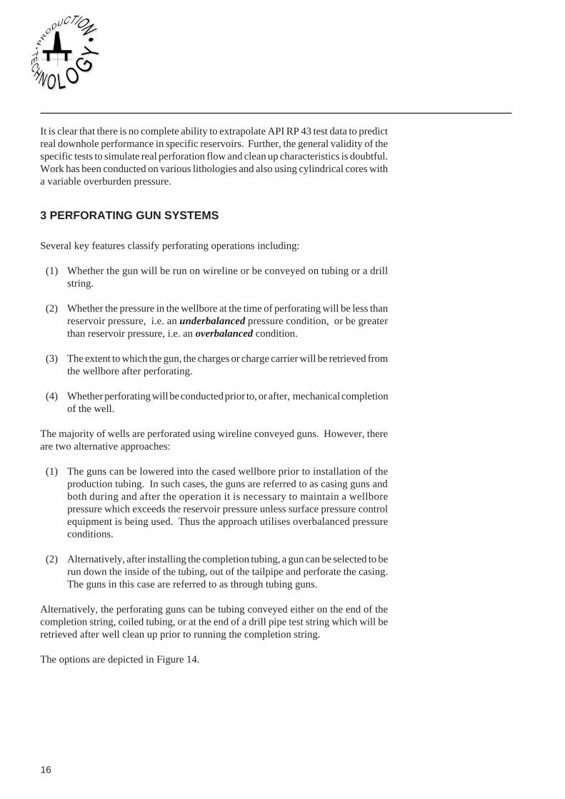
The majority of wells are perforated using wireline conveyed guns. However, thereare two alternative approaches:
(1) The guns can be lowered into the cased wellbore prior to installation of theproduction tubing. In such cases, the guns are referred to as casing guns andboth during and after the operation it is necessary to maintain a wellborepressure which exceeds the reservoir pressure unless surface pressure controlequipment is being used. Thus the approach utilises overbalanced pressureconditions.
(2) Alternatively, after installing the completion tubing, a gun can be selected to berun down the inside of the tubing, out of the tailpipe and perforate the casing.The guns in this case are referred to as through tubing guns.
Alternatively, the perforating guns can be tubing conveyed either on the end of thecompletion string, coiled tubing, or at the end of a drill pipe test string which will beretrieved after well clean up prior to running the completion string.
The options are depicted in Figure 14.
Department of Petroleum Engineering, Heriot-Watt University 17
88Perforating
Through tubing
wireline guns
Wireline conveyed
casing guns
Tubing conveyed
guns
Perforating guns also vary according to the extent to which they are expendable, andare classed as follows:
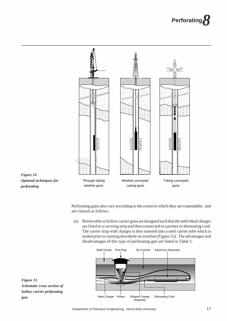
(a) Retrievable or hollow carrier guns are designed such that the individual chargesare fitted to a carrying strip and then connected to a primer or detonating cord.The carrier strip with charges is then inserted into a steel carrier tube which issealed prior to running downhole on wireline (Figure 15). The advantages anddisadvantages of this type of perforating gun are listed in Table 1.
Port Plug Air CushionSteel Carrier
PrimerMain Charge Shaped ChargeAssembly
Detonating Cord
Electronic Detonator
Figure 14
Optional techniques for
perforating
Figure 15
Schematic cross section of
hollow carrier perforating
gun

18
Retrievable Robust and less liable to Gun length is limited by heighthollow be damaged during running availability for handling orcarrier gun in charges protected from: lubricator size (normally 60'
(a) well fluids max). Weight of hollow carrier (b) well pressure can be significant. (c) well temperature Large intervals to perforatedFast running speeds into the will require multiple runs.well bore.No debris
Fully Flexible and thus can be run Debris left in wellbore.expendable in longer lengths (up to 200 Components immersed in wellguns ft per run). fluids.
Most economical in terms of Pressure and temperature mayboth gun cost and time. limit the use of certain charges.required. The gun is not rigid nor durable
and maylimit running in speedsor tension to be pulled if gunbecomes stuck.
Semi - Debris limited to crushed Rigid carrier strip constrainsexpandable charge cases. gun length as for hollow carrier
More economical than hollow guns.carrier guns. Charges may suffer pressure
and temperature limitationssince they are immersed in well fluids.
Advantages Disadvantages
(b) Expendable perforating guns are designed such that the gun will self-destructon detonation and thus only the connectors and depth correlation equipmentwill be retrieved from the well. Such guns comprise a number of charges whichare essentially strung together, i.e. no rigid carrier strip or tube is used. Thecharges are also designed such that the charge case or container will fragment/ disintegrate on detonation. The material used for fabrication of the charge casemust be friable, e.g. ceramic or aluminium, but must offer a reasonabledegree of robustness to protect the charges during handling operations.
Since the assembled gun is not rigid, the length of gun which can be used is notlimited by height availability or lubricator size. Table 1 lists some of the importantadvantages and limitations of these guns.
(c) Semi expendable perforating guns are designed to offer the advantages of gundurability and robustness which exist with the hollow carrier and the chargedisintegration of fully expendable guns. The guns are designed such that thecharges which are expendable are mounted on a carrier strip for running into thewellbore.
3.1 Wireline Conveyed Casing GunsThese guns are largely constrained by two factors:
(1) The gun diameter must be less than the casing inside diameter. This allows alarge diameter gun to be used and hence large charges.
(2) The length of gun is defined by either the weight which can safely be suspendedby the wireline or by the length of lubricator into which the gun will be retrievedafter perforating in underbalanced conditions.
Table 1
Comparison of retrievable,
expendable and semi
expendable perforating
guns
Department of Petroleum Engineering, Heriot-Watt University 19
88Perforating
Thus, guns are normally in the range of 3 3/8" to 5" diameter and have the following
advantages:(1) The gun diameter can allow for the use of fairly large explosive loads in the
shaped charges.
(2)The gun diameter which can be run into the well must allow for a minimumclearance of 1/
2". However if the gun size is fairly large there will be reduced
standoff or clearance for the charges, and such guns can take full advantage of90° shot phasing to provide improved flow performance.
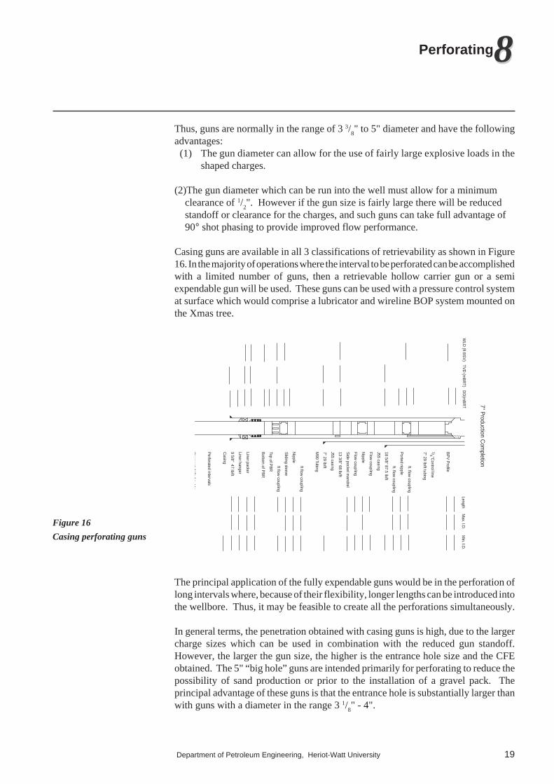
Casing guns are available in all 3 classifications of retrievability as shown in Figure16. In the majority of operations where the interval to be perforated can be accomplishedwith a limited number of guns, then a retrievable hollow carrier gun or a semiexpendable gun will be used. These guns can be used with a pressure control systemat surface which would comprise a lubricator and wireline BOP system mounted onthe Xmas tree.
7" Production C
ompletion
WLD
(ft BS
V) TV
D (m
BR
T) DD
(mB
RT
Length Max. I.D
. Min. I.D
.
BP
V P
rofile
1/4 "Control line
7" 29 lb/ft tubing
ft. flow coupling
Ported nipple
ft. flow coupling
18 5/8" 87.5 lb/ft
J55 casing
Flow coupling
Nipple
Flow coupling
Side pocket m
andrel
13 3/8" 68 lb/ft
J55 casing
7" 29 lb/ft
M90 Tubing
ft flow coupling
Nipple
Sliding sleeve
ft flow coupling
Top of PB
R
Bottom
of PB
R
Liner packer
Liner hanger
9 5/8" 47 lb/ft
Casing
Perforated intervals
Cerm
entdrilledo
tto
The principal application of the fully expendable guns would be in the perforation oflong intervals where, because of their flexibility, longer lengths can be introduced intothe wellbore. Thus, it may be feasible to create all the perforations simultaneously.
In general terms, the penetration obtained with casing guns is high, due to the largercharge sizes which can be used in combination with the reduced gun standoff.However, the larger the gun size, the higher is the entrance hole size and the CFEobtained. The 5" “big hole” guns are intended primarily for perforating to reduce thepossibility of sand production or prior to the installation of a gravel pack. Theprincipal advantage of these guns is that the entrance hole is substantially larger thanwith guns with a diameter in the range 3 1/
8" - 4".
Figure 16
Casing perforating guns
20
Casing guns can normally provide perforations which are larger in diameter anddeeper than those obtained with through tubing wireline guns. Their size provides anopportunity to use not only larger explosive charges but also higher shot densities.
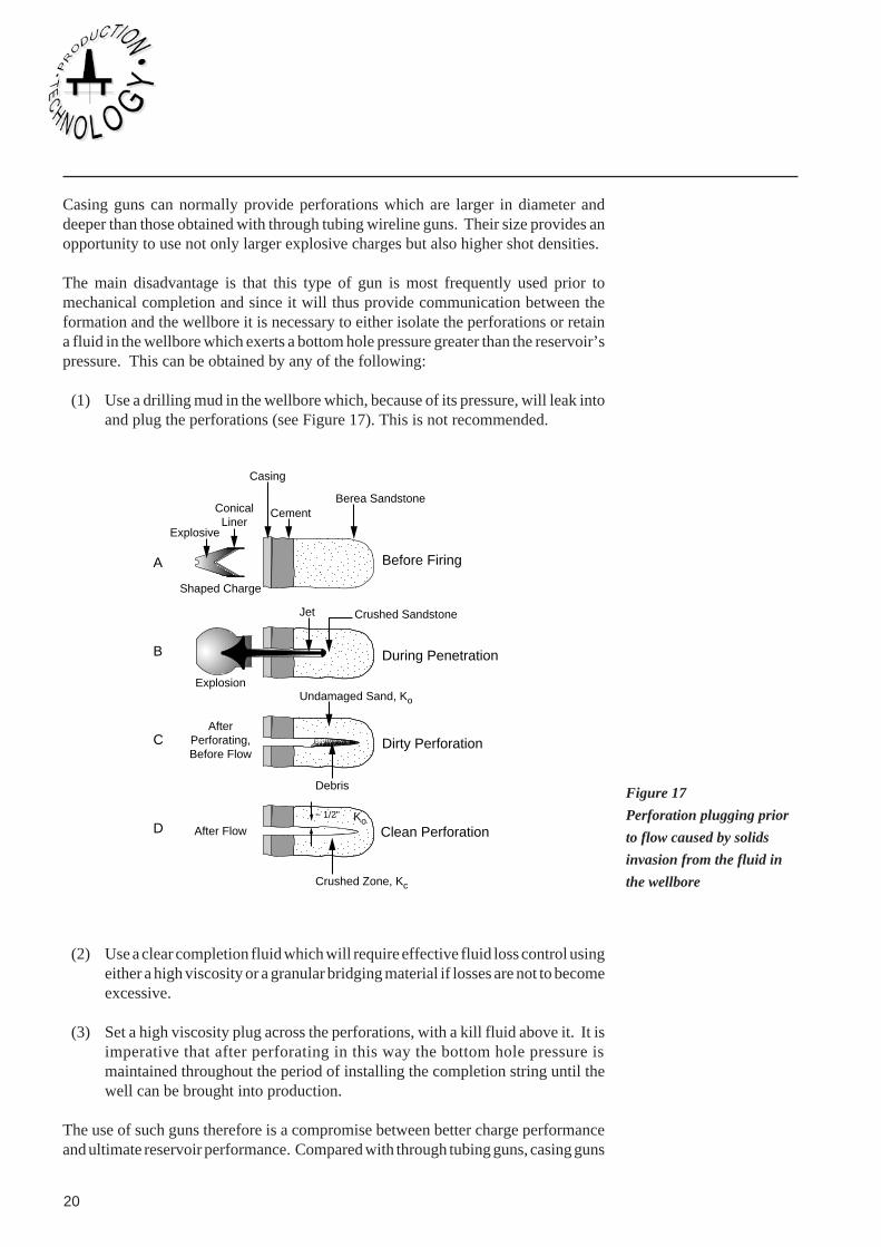
The main disadvantage is that this type of gun is most frequently used prior tomechanical completion and since it will thus provide communication between theformation and the wellbore it is necessary to either isolate the perforations or retaina fluid in the wellbore which exerts a bottom hole pressure greater than the reservoir’spressure. This can be obtained by any of the following:
(1) Use a drilling mud in the wellbore which, because of its pressure, will leak intoand plug the perforations (see Figure 17). This is not recommended.
Casing
Berea Sandstone
Crushed SandstoneJet
Undamaged Sand, Ko
Ko
Debris
Crushed Zone, Kc
CementConicalLiner
Explosive
Shaped Charge
Explosion
AfterPerforating,Before Flow
After Flow
Before Firing
During Penetration
Dirty Perforation
Clean Perforation~ 1/2"
A
B
C
D
(2) Use a clear completion fluid which will require effective fluid loss control usingeither a high viscosity or a granular bridging material if losses are not to becomeexcessive.
(3) Set a high viscosity plug across the perforations, with a kill fluid above it. It isimperative that after perforating in this way the bottom hole pressure ismaintained throughout the period of installing the completion string until thewell can be brought into production.
The use of such guns therefore is a compromise between better charge performanceand ultimate reservoir performance. Compared with through tubing guns, casing guns
Figure 17
Perforation plugging prior
to flow caused by solids
invasion from the fluid in
the wellbore
Department of Petroleum Engineering, Heriot-Watt University 21
88Perforating
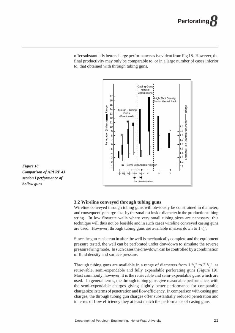
offer substantially better charge performance as is evident from Fig 18. However, thefinal productivity may only be comparable to, or in a large number of cases inferiorto, that obtained with through tubing guns.
- Semi-Expandable Version
Ent
ranc
e H
ole
Dia
met
er (
Inch
es)
R
ange
Pen
etra
tion
(Inc
hes)
R
ange
1.0
17
16
15
14
13
12
11
10
9
8
7
6
5
4
3
2
1
0.9
1.8
1.7
1.6
1.5
1.4
1.3
1.2
0.1
Through - TubingGuns
(Positioned)
High Shot DensityGuns - Gravel Pack
Casing GunsNatural
Completions
138
4 5 611116
2 18
2 12
2 78
3 18
3 58
Gun Diameter (Inches)
3.2 Wireline conveyed through tubing gunsWireline conveyed through tubing guns will obviously be constrained in diameter,and consequently charge size, by the smallest inside diameter in the production tubingstring. In low flowrate wells where very small tubing sizes are necessary, thistechnique will thus not be feasible and in such cases wireline conveyed casing gunsare used. However, through tubing guns are available in sizes down to 1 3/
8".
Since the gun can be run in after the well is mechanically complete and the equipmentpressure tested, the well can be perforated under drawdown to simulate the reversepressure firing mode. In such cases the drawdown can be controlled by a combinationof fluid density and surface pressure.
Through tubing guns are available in a range of diameters from 1 3/8" to 3 1/
2", as
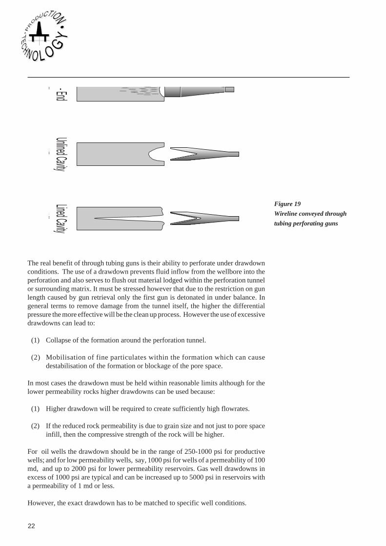
retrievable, semi-expendable and fully expendable perforating guns (Figure 19).Most commonly, however, it is the retrievable and semi-expendable guns which areused. In general terms, the through tubing guns give reasonable performance, withthe semi-expendable charges giving slightly better performance for comparablecharge size in terms of penetration and flow efficiency. In comparison with casing guncharges, the through tubing gun charges offer substantially reduced penetration andin terms of flow efficiency they at least match the performance of casing guns.
Figure 18
Comparison of API RP 43
section I performance of
hollow guns
22
- Endff
Unlined CavityEff
Lined CavityEff
The real benefit of through tubing guns is their ability to perforate under drawdownconditions. The use of a drawdown prevents fluid inflow from the wellbore into theperforation and also serves to flush out material lodged within the perforation tunnelor surrounding matrix. It must be stressed however that due to the restriction on gunlength caused by gun retrieval only the first gun is detonated in under balance. Ingeneral terms to remove damage from the tunnel itself, the higher the differentialpressure the more effective will be the clean up process. However the use of excessivedrawdowns can lead to:
(1) Collapse of the formation around the perforation tunnel.
(2) Mobilisation of fine particulates within the formation which can causedestabilisation of the formation or blockage of the pore space.
In most cases the drawdown must be held within reasonable limits although for thelower permeability rocks higher drawdowns can be used because:
(1) Higher drawdown will be required to create sufficiently high flowrates.
(2) If the reduced rock permeability is due to grain size and not just to pore spaceinfill, then the compressive strength of the rock will be higher.
For oil wells the drawdown should be in the range of 250-1000 psi for productivewells; and for low permeability wells, say, 1000 psi for wells of a permeability of 100md, and up to 2000 psi for lower permeability reservoirs. Gas well drawdowns inexcess of 1000 psi are typical and can be increased up to 5000 psi in reservoirs witha permeability of 1 md or less.
However, the exact drawdown has to be matched to specific well conditions.
Figure 19
Wireline conveyed through
tubing perforating guns
Department of Petroleum Engineering, Heriot-Watt University 23
88Perforating
Through tubing perforating is a most widely applied method and offers a reasonablecompromise between charge performance, well productivity and safety.
3.3 Tubing conveyed perforating gunsAs the name implies, tubing conveyed perforating, or TCP, involves the assembly ofa perforating gun on the end of drill pipe string, production tubing or coiled tubing andits lowering and positioning in the wellbore prior to detonation. The technique hasincreased rapidly in both application and development during the 1970s and is nowwidely employed. After detonation, the gun can either be pulled from the well ordetached to drop into the wellbore sump below the perforated interval.
3.3.1 Deployment OptionsTubing conveyed perforating can either be employed by:
(1) Running the guns with a conventional drill stem test assembly as shown inFigure 20a. After clean up, the well would have to be killed prior to retrievingthe test string, normally with the spent gun. Subsequently, the well wouldbe completed if required.
(2) The gun could be run attached to the base of the completion string tailpipebelow the packer. The string would be run into the hole, landed off, the packerset and the gun detonated under drawdown. Normally, the guns would bedetached and dropped into the sump (see figure 20b).
(3) Running and retrieving the gun on coiled tubing using a CT deployment system.

24
Options:APR valveHydra springKnock out disk
Retrievable packer
Ported debris barrier
Water filled tubing
Centralizer housing
Pup joint
Perforating guns
Permanent packer
Tubing release sub
Ported debris barrier
Water filled tubing
Centralizer housing
Pup joint
Perforating guns
Temporarycompletion
Permanentcompletion
(a) (b)
3.3.2 Firing OptionsWhen the gun is in position, it can be detonated by one of a number of optionaltechniques:
(1) Mechanical firingA bar or go-devil can be dropped down the tubing onto a plunger which contacts ablasting cap on top of the gun. An inferior method is to incorporate the blasting capon the bar which is dropped downhole. This method can be unreliable if debris isallowed to accumulate on top of the firing head. This potential problem can bealleviated by running a ported debris barrier which will allow circulation above thefiring head prior to detonation. Apart from surface pressure, there is no reliableindication of detonation and this can lead to uncertainties regarding safety if the stringhas to be pulled.
(2) HydromechanicalIn this technique, the annulus can be pressured up and the pressure routed through abypass valve above the packer, onto a series of shear pins on the firing head. Once adifferential pressure is exerted sufficient to shear the pins, the firing pin is driven down
Figure 20
Common configuration for
TCP system
Department of Petroleum Engineering, Heriot-Watt University 25
88Perforating
against the detonator. This technique would be more reliable than the mechanicalmethod, especially in deviated wellbores.
(3) Wireline firingIn this system, a special wet connect is run on wireline after the guns are positioned.This wet connect attaches to the firing head which can then be fired by passing anelectrical current down the cable from surface. The main advantage of this techniqueis that, besides surface pressure being created on successful firing, there are alsoelectrical indications at the surface.
3.3.3 TCP Gun DisposalAfter detonation the gun can be dropped. However, if it is decided to flow the welleither before detaching the gun, or if it is intended to retrieve the gun, a vent assemblyor perforated joint must be provided below the packer where fluid can enter the flowstring.
3.3.4 Advantages / Disadvantages of TCPA major advantage of TCP is that as with using casing guns, the gun size and,accordingly, that density and charge size can be quite large. Given the size of the guns,it would be expected that the charges would offer deep penetration with large entrancehole size and good flow efficiency. The principal advantages of TCP are that it canoffer the ability to use large charges with high shot density (up to 16 shots/ft) andperforate under substantial drawdown if required. It therefore combines some of theadvantages of casing and through tubing guns.
The advantages of tubing conveyed guns are:
(1) The ability to use high shot densities and to create large entrance hole sizes canlead to reduced hydraulic erosion in the formation around the perforations. Thisallows higher flowrates to be realised without formation breakdown.
(2) The perforating operation can be completed in one run even for long intervals.Intervals in excess of 1000 m have been shot in one run with TCP.
(3) Unlike wireline operations, even if the interval is fairly large, the ability to shootthe interval with one gun means that all the perforations are createdsimultaneously, which benefits well clean up and productivity.
(4) As with the through tubing techniques the well is not perforated until the wellis completed and it is safe to allow well fluids to enter the wellbore.
(5) With wireline conveyed guns, whilst perforating under drawdown, there is adanger that the guns will be damaged or blown up the wellbore if too high apressure drawdown is used. With TCP, the durability of the system allows highdifferential pressures, e.g. >2500 psi, to be used.
(6) If the hydromechanical firing option is used the technique is feasible, even inhighly deviated wells, as there is no dependence on wireline nor on a go devildetonation system.

26
(7) If either the mechanical or hydromechanical firing system is used there is nonecessity for radio silence.
The disadvantages of TCP are:
(1) If a misfire occurs, then gun retrieval will require a round trip which is both timeconsuming and costly. There is also a safety concern as to why the gun hasnot detonated. Detonation whilst the string is being retrieved, although rare, hasoccurred.
(2) If the gun is not detached but is to remain opposite the perforated interval, it willprevent production logging or through tubing wireline below the tailpipe.
(3) Since the running procedure for the guns is prolonged, the charges may beexposed to well temperatures for an extended period and this may lead todegradation.
(4) In general, the costs of TCP are higher than conventional wireline perforating.The cost differential will decrease as the length of interval to be perforatedincreases. Further, if the gun is to be dropped into the sump the cost ofdrilling the additional sump length must be considered.
(5) Surface observation of the degree to which the charges have fired is not possibleunless the gun is retrieved.
4 OPERATIONAL CONSIDERATIONS
Exphasis has been placed in the previous sections upon the concepts of perforating andcharge performance. In this section operational considerations will be discussed.
4.1 Surface pressure equipment
The majority of perforating operations are conducted under conditions of underbalanced pressure. In the case of through tubing guns particularly, there will be a needto allow retrieval and removal of the gun from the well on which there will exist a THPafter perforating. There will therefore be a need to assemble a lubricator and wirelineBOP in much the same manner as for the conventional slick wireline. Normally botha hydraulically actuated and a manual BOP valve are located at the base of thelubricator. In addition, since the gun will be lowered on a braided electrical conductorcable, the sealing of pressure as the cable leaves the lubricator will be a seriousproblem. In conventional slick line, a stuffing box can be reasonably effective on asingle strand line. However, when perforating, sealing is provided by grease injectionthrough a port into a flow-tube through which the cable passes.
4.2 Depth correlationA reservoir can either be blanket perforated in which most of the reservoir is perforatedwith little selectivity, or alternatively selectively perforated over a reduced interval(s).The latter case is perhaps more prevalent, and it will therefore be necessary to ensure

Department of Petroleum Engineering, Heriot-Watt University 27
88Perforating
that the perforating guns be located at the required depth prior to firing. A number ofwireline techniques are available for depth correlation against previous wireline logs:-
(1) Gamma Ray Log GRA gamma ray log can measure the shaliness of a formation even behind a casing. Sincethe log is widely run, a log will normally be available at the time of perforation forcorrelation. Thus a gamma ray log is frequently incorporated above the perforatinggun and used to depth correlate against a previous gamma-ray log.
(2) Casing Collar Locator CCLA casing collar locator log monitors the location of casing couplings in that it respondsultrasonically to the wall thickness of steel. This log is normally run with a cementbond log CBL or cement evaluation tool after casing cementation. A CCL can be runabove the perforating gun and used to monitor casing collar location for depthcorrelation against a previous log. However, since most casing joints are similar inlength, confusion as to the exact depth can occur. This can be prevented by installinga smaller pup joint (10' or 20') in the original casing string, located in the proximityof the top of the reservoir. This joint will act as a marker and ease exact depthcorrelation.
(3) Nuclear LogsIt is possible to use nuclear logs such as the Compensated Nuclear Log CNL as thesewill respond to fluid saturation/porosity behind the casing. However, given that theselogs utilise a nuclear source, they are less frequently used in conjunction withperforating guns.
In most cases a combination of CCL and GR is used and using these techniques itshould be possible to depth correlate to with a minimum of 1-2 ft. of the required depth.In the case of TCP, a radioactive source is frequently used for depth correlation.
4.3 Safety procedures
It is well recognised that explosives of any sort should be handled with extreme care.In most cases the charges themselves do not pose any real danger until they areassembled in the gun and the gun is armed.
For wireline conveyed guns where the guns will be detonated by an electrical currentsignal passed down the cable, there is real concern that the gun could be accidentallydetonated by stray current. When using wireline guns there is a need to observe certainprecautions aimed at eliminating sources of stray current. Some of the safety rulesnormally applied are as follows:-
(1) Radio silence to be observed on the rig and adjacent to the location.
(2) No welding.
(3) No crane operation.
(4) No high amperage lights in the drill floor vicinity.

28
(5) Shutdown temporarily cathodic protection system if working offshore.The danger of stray current detonating the gun exists from the time the gun isarmed until it has been run to a safe depth downhole, say a minimum of 500ft.below the sea bed. The shutdown safety procedure should also be observed inretrieving the gun until the gun has been checked to ensure that all the chargeshave fired.
In the case of TCP, the above concerns of stray current will also apply to those gunswhich use an electrical detonation system.
As an attentive safety shutdown system are available which will isolate the gun in theevent of a stray detonation current source.
4.4 Gun length/perforated intervalThe length of gun which can be used in the case of retrievable or semi expendable gunsis limited by the lubricator length and in the care of larger gun diameters, the tensilestrength of the cable. Normally the gun will be between 15 - 40ft. If the requiredperforated interval is larger than this, then multiple trips with perforating guns willbe necessary. In such cases
The lubricator provides the necessary well security. Perforating usually starts at thelowest interval in the zone or the interval with the lowest permeability and movesupwards on successive runs.
4.5 Perforating multiple zonesIf, for example, 3 intervals each 10ft. in length are required to be perforated it ispossible to make up a single gun which comprises 3 sections and can be detonated witha switch system.
If the zones are large, they will normally be perforated separately with individual guns.
4.6 Temperature effectsExplosive charges can spontaneously detonate if exposed to high temperature. TheRDX explosive will detonate at 340°F. Other explosives are available which are morestable at temperatures in excess of 500°F. However, the stability is also affected bythe duration of exposure. In most wireline perforating operations, the gun will neverwarm up to bottom hole temperature because of the thermal lag and the fact that in anewly completed well, the completion fluid will perhaps not have had time to warmup. However, such benevolent effects cannot normally be relied upon and theexplosive charge should be selected appropriate to the anticipated well temperature.
However, in the case of TCP, the deviation of exposure of the charges in increased andthe possibility of spontaneous detonation potentially more dangerous.
4.7 Casing DamageThe present trend is to use large charges (largest diameter gun) with higher shotdensities. However, the possibility of casing damage is increased in these situations.In general terms, casing damage will be influenced by:-

Department of Petroleum Engineering, Heriot-Watt University 29
88Perforating
(1) Casing steel grade and consequent compressive strength.
(2) The quality of the cement sheath and the extent to which it provides radialsupport to the casing.
(3) The shot density, the number of shots in any plane will influence the stress onthe casing during perforating.
The damage, if it occurs, is likely to be in the form of splits along the casing wallin the axial direction between perforations. This is clearly undesirable and should beavoided at all costs.
4.8 Gun orientation
There are two particular situations where it is either desirable or essential to orientatethe gun to perforate in a specific direction.
(1) In deviated wells, where the gun size is substantially smaller than the casingsize, the degree of gun clearance due to the lack of centralisation will affectcharge performance. In such cases it is frequently more beneficial to use 0°phasing and a magnetic positioning device to position the gun to fire in the lowside of the hole where the gun is in contact with the casing. To further improvethe effectiveness of this approach, a series of retrievable hollow carrier gunsknown as scallop guns were developed. The scallop gun as depicted in Figure21, has part of the carrier wall machined opposite the charge to reduce the wallthickness of the steel carrier and provide optimum standoff. A furtherrefinement is the hyperdome scallop which is designed to reduce the energy ofthe jet consumed in perforating through the carrier.
Regular scallop gun New hyper - dome scallop gun
Unique hyper - domescallop design results inperformance gains
(2) If it is decided to run through tubing guns to perforate a dual or triplecompletion, there will be a requirement to orientate the gun whilst perforatingthe upper zone to avoid perforating the longer strings which will produce thelower zones. In such cases a radioactive isotope can be installed in the longstring and the gun lowered through the short string with an orientation tool.
Figure 21
Scallop and hyperdome
scalop guns

30
4.9 Charge qualityAn investigation by King et al has attempted to verify the extent to which charges liveup to the expectations indicated by their quoted performance in the API RP.43 tests.It is clear that whilst some of the charges did in fact meet the quoted performance, alarge number gave inferior performance. A large number of factors could influencethis, including the age of the charges and the conditions under which they have beenstored.
Department of Petroleum Engineering, Heriot-Watt University 31
88Perforating
EXERCISE 1.
Jet Perforator Penetration as a Function of Compressive Strength
To convert from test data for perforation penetration obtained for API RP 43 we canuse
Ln Pf = Ln Pt + 0.086 x (Ct - Cf) / 1000
Where:
Pf = Expected penetration in formation with a compressive strength of Cf psiPt = Test perforation based on Ct = 6500 psi
Two gun systems are being assessed for deployment for perforating:
1. 2 1/8" scallop through tubing (T.T.) gun giving 12" penetration in Berea sst.
2. 4" wireline (W/L) conveyed casing gun, giving 17" penertration.
Compare the guns for the following scenario:
1. Both guns for use with a low compressive strength chalk reservoir with Cf of4000 psi.
2. Both guns for use with a deep high compressive strength rock withcompressibilities of 12000 and 18000 psi respectively.
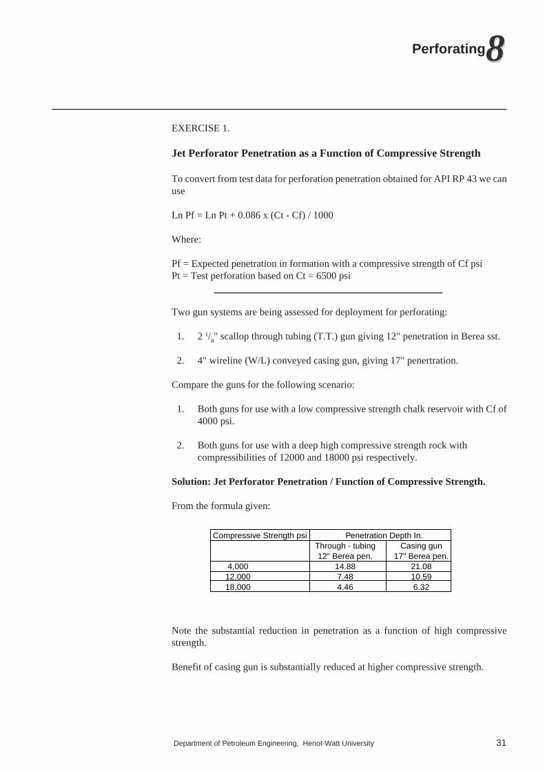
Solution: Jet Perforator Penetration / Function of Compressive Strength.
From the formula given:
Compressive Strength psi Penetration Depth In.Through - tubing Casing gun12" Berea pen. 17" Berea pen.
4,000 14.88 21.0812,000 7.48 10.5918,000 4.46 6.32
Note the substantial reduction in penetration as a function of high compressivestrength.
Benefit of casing gun is substantially reduced at higher compressive strength.