KA 017F/00/a6/05.00 016085-0000 Software 2.3 Hauser + Endress The Power of Know How Prosonic FMU 860 d Kurzanleitung Füllstandmessung e Quick Reference Guide Level Measurement f Mise en service condensée niveaumétrie es Manual breve de instalación para la medición de nivel i Manuale breve di installazióne per la misura di livello nl Verkorte handleiding niveaumeting - VH FMU 860 FDU

Welcome message from author
This document is posted to help you gain knowledge. Please leave a comment to let me know what you think about it! Share it to your friends and learn new things together.
Transcript

KA 017F/00/a6/05.00016085-0000Software 2.3
Hauser+EndressThe Power of Know How
ProsonicFMU 860
d Kurzanleitung Füllstandmessung
e Quick Reference Guide Level Measurement
f Mise en service condensée niveaumétrie
es Manual breve de instalación para la medición de nivel
i Manuale breve di installazióne per la misura di livello
nl Verkorte handleiding niveaumeting
-
V H
FMU 860
FDU

d Sicherheitshinweise
f Conseils de sécurité
e Safety Instructions
Qualifikation• Montage, elektrische Installation, Inbetriebnahme, Wartung und Bedienung des Gerätes darf
nur durch ausgebildetes Fachpersonal erfolgen, das vom Anlagenbetreiber dazu autorisiert wurde. Das Fachpersonal muß diese Kurzanleitung und die BetriebsanleitungBA 100F gelesen und verstanden haben und die Anweisungen befolgen.
Note• Mounting, electrical installation, start-up, maintenance and operation of the instrument are
only to be carried out by trained personnel authorised by the operator of the plant. The personnel must read, understand and follow the instructions given in this quick reference guide and the operating manual BA 100F.
Qualification• Le montage, l’installation électrique, la mise en service, la maintenance et l’utilisation de
l’appareil ne doivent être confiés qu’à un personnel spécialisé autorisé par l’utilisateur del’installation. Ce personnel devra lire les instructions contenues dans la présente mise enservice condensée ainsi que dans le manuel complet BA 100F et les appliquer rigoureusement.
2

FMU860-R1A1 1• Standardausführung / Standard version / Standard version
• Gehäuse / Housing / Boitier
• Tastatur und Display auf der Frontplatte / Keypad and display on front panel /Clavier et affichage en face frontale
• Drei Relais / Three relays / Trois relais
• Spannungsversorgung / Power supply / Tension d’alimentation– A: 180…253 V, 50/60 Hz– B: 90…132 V, 50/60 Hz– C: 38…55 V, 50/60 Hz– D: 19…28 V, 50/60 Hz– E: 20…30 V (DC)
• Ohne Kommunikationsprotokoll /No communication protocol / Sans protocole de communication
d Geräte-Identifikation• Diese Kurzanleitung beschreibt die wesent-
lichen und erfahrungsgemäß am häufigstenbenutzten Einstellungen zur Füllstandmes-sung mit dem FMU 860. Sie gilt für alle Geräte, auf deren Typenschild der CodeFMU860-R1A1 1 angegeben ist.
• Eine vollständige Übersicht über alleFunktionen der Geräte Prosonic FMU 860…862 gibt Betriebsanleitung BA 100F.
f Identification de l’appareil • Cette mise en service condensée décrit les
principaux réglages ou ceux le plus fréquemment utilisés pour la mesure de niveau avec le FMU 860. Elle est valablepour tous les appareils portant le codeFMU860-R1A1 1 sur la plaquesignalétique.
• Toutes les fonctions des appareils Prosonic860...862 sont décrites dans la mise en service BA 100F.
e Instrument Identification• This quick reference guide describes the
most important settings for level measurement with the FMU 860 which arecommonly met in practice. This applies toall instruments which have nameplates withthe markings FMU860-R1A1 1.
• A complete summary of all functions for theProsonic FMU 860...862 is given in the operating manual BA 100F.
ENDRESS+HAUSERPROSONIC FMU 860
FMU860–R1A1 1
U: XX V AC+XX / XX/XX HZP: 15 VA
IP 66
Ser.No.: XXXXXXXXXXXPat.
NEMA 4X
TypenschildNameplatePlaque signalétique
3

d Elektrischer Anschluß
f Raccordement électrique
e Electrical Connection
• Vor allen Arbeiten an der Anschlußleiste Spannungsversorgung ausschalten.• Überprüfen, ob Versorgungsspannung mit der am Typenschild angegebenen übereinstimmt• Bei der Installation des Sensorkabels beachten:
– Bei Leitungslängen bis 300 m Klemmenkasten verwenden– Abschirmung nicht erden– Abschirmung ohne elektrische Unterbrechung vom Sensor bis zum Auswertegerät führen– FDU 83, 84, 85, 86: Leitung für Potentialabgleich nicht innerhalb der Abschirmung mitführen– Abschirmung: Metallgeflecht max. 6 Ω, – Kabelspezifikation (pro Ader): max. 6 Ω, max. 60 nF Gesamtkapazität
• Bei der Verdrahtung von mehreren Prosonic-Geräten müssen die Synchronisations-anschlüsse verdrahtet werden (siehe BA 100F).
• Les travaux de raccordement doivent être réalisés hors tension• Vérifier que la tension d’alimentation correspond aux valeurs indiquées sur la plaque
signalétique• Lors de la pose du câble de sonde:
– en cas de longueurs jusqu’à 300 m, utiliser une boite de jonction– ne pas mettre le blindage à la terre– prévoir un blindage ininterrompu depuis le capteur jusqu’au transmetteur– FDU 83, 84, 85, 86: ne pas prévoir le conducteur de mise à la masse à l’intérieur du blindage– blindage: tresse métallique max. 6 Ω– spécifications de câble (par conducteur): max. 6 Ω, max. 60 nF de capacité totale
• Lorsque plusiers câbles de liaison FMU/FDU doivent être posé côte à côte, il est conseillé derelier les Prosonic FMU entre eux via les bornes de synchronisation (voir BA 100F).
• Switch off the power supply to the connecting strip before carrying out any work on the instrument
• Check that the power supply agrees with that stated on the nameplate• When installing the sensor cable ensure that:
– Terminal boxes are used for cables up to 300 m– The screening is not grounded– The screening is continuous without any electrical breakage between the sensor and the transmitter– FDU 83, 84, 85, 86: the potential compensation cable is not laid within the screening– Screening: metal strands max. 6 Ω– Cable specifications (per wire): max. 6 Ω , max. 60 nF as total capacitance
• When several Prosonics are connected together, the synchronisation connections must alsobe made (see BA 100F).
4

FDU 80/80F/81/81F/82
BK YE RD
80 8182 80 8182
FDU 83/84/85/86
BKGNYE YE RD
80 8182
FDU 80/81
BN BU BKYE RD
80 8182
BKGNYE YERD
FDU 83/84/85/86
1 2 3 4 5
8011 21 31 41 51 6160 8112 22 32 42 52 62 8213 23 33 43 53 63 7064 71
L+ L-
L1 N l +1 l +2 YE RD
1 2 3 5 6 74
Stromcurrentsortie analogique
Relaisrelaysrelais
Sensorsensorsonde
erdengroundingbarrette de terre
Speisegerätpower supply unitalimentation
Erdung am Klemmenkastengrounding at the terminal boxmise à la terre dans la boite dejonction
Erdung am FMUgrounding at the FMUmise à la terre au FMU
mit Heizungwith heatingavec chauffage
Abschirmungscreeningblindage
5
➀ Symbole decommunication(Seulement pour versionavec protocole decommunication)
➁ Paramètre de la case matricielle sélectionnée(clignote lors de la programmation)
➂ Coordonnées matricielles sélectionnées
➃ Dépassement de signal Courant supérieur à 20 mA
➄ Affichage bargraph représentatif du signal analogique
➅ Dépassement de signalCourant inférieur à 0/4 mA
➆ Symbole de défaut allumé: défautclignote: avertissement,l’appareil essaye de poursuivre la mesure
➀ Communication signal(only with versions having acommunications protokoll)
➁ Parameter of the matrixfield (flashes during operation)
➂ Matrix field
➃ Signal overrunCurrent greater than 20 mA
➄ Bar display of current
➅ Signal underrunCurrent smaller than 0/4 mA
➆ Symbol for error indicationLit: FaultFlashing: Warning, the instrument tries to continue measuring
➀ Kommunikationssignal (nur bei Version mit Kommunikationsprotokoll)
➁ Parameter des gewählten Matrixfeldes(blinkt bei der Bedienung)
➂ Matrixfeld
➃ Signalüberlauf Strom größer als 20 mA
➄ Segmentanzeige desStroms
➅ Signalunterlauf Strom kleiner als 0/4 mA
➆ Symbol zur Fehlermeldungleuchtet: Störungblinkt: Warnung, das Gerätversucht weiterzumessen
d Display
f Affichage
e Display
V H
➀ ➁ ➂
➃➄➅
➆
6

d Bedienung• Der FMU wird über eine 10x10-Felder
Matrix bedient (siehe Seite 18/19)• Jedem Feld der Matrix ist eine Funktion
zugeordnet.
V H
H
+ H
➀
V H
+
➁
E➂
➀ Matrixfeld wählen mit V und H • der Parameter im angewählten Matrixfeld
blinkt und kann verändert werden• Hinweis: Bei gleichzeitigem Drücken von V
und H springt die Anzeige auf V0H0
➁ Parameter ändern mit + , – , →• Hinweis: Bei gleichzeitigem Drücken von V
und → springt der Dezimalpunkt eine Stellenach rechts.
➂ Eingabe bestätigen mit Enter
f Commande• Le FMU est programmable par le biais
d’une matrice 10x10 (voir page 18/19)• A chaque case de la matrice est attribuée
une fonction.
e Operation• The FMU is operated using a 10x10-field
matrix (see page 18/19)• A function is assigned to every field of the
matrix.
➀ Select matrix field with V and H keys• The parameter in the selected field flashes
and can be changed• Note: The display jumps to V0H0 when V
and H are pressed simultaneously
➁ Change the parameter using the keys +,–, →
• Note: The decimal point moves one position to the right when V and → are pressed simultaneously.
➂ Confirm input with E
➀ Sélectionner la case matricielle avec V et H
• le paramètre sélectionné dans la case clignote et peut être modifié
• remarque : en activant simultanément V et H l’affichage passe à V0H0
➁ Modifier les paramètres avec +, – , →• remarque: en activant simultanément V et
→ la décimale se déplace d’un rang vers ladroite
➂ Valider l’entrée avec Enter
7

AbgleichCalibrationEtalonnage
GrundeinstellungenBasic settingsRéglage de base
MeßwertanzeigeDisplay of measured valueAffichage de la mesure
Eingabe KundeneinheitEntering technical unitsLinéarisation pour afficage en unité technique
Verhalten bei StörungResponse on faultComportement en cas de défaut
FehlerdiagnoseTrouble-shootingRecherche de défauts
RelaisRelayRelais
AnalogausgangAnalogue outputSortie analogique
10
9
11
12
13
15
16 17
d Parametrierung• Nach jedem Parametrierungsschritt können
die aktuellen Meßwerte abgefragt werden.• Für Funktionen, die nicht parametriert
werden, gelten die Werkseinstellungen.
f Programmation• Après chaque pas de programmation il est
possible d’interroger les valeurs de mesureactuelles.
• Pour les fonctions non programmées cesont les réglages par défaut qui sontvalables.
e Calibration• The actual measured values can be called
up after each calibration step.• Factory settings are used for those
functions not calibrated.
8
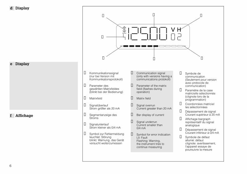
Anzeige Display AffichageV0H0 Meßwert (% oder
beliebiger Maßeinheit)Meas. value (% or inunits selected)
Valeur mesurée(% ou unité technique)
V0H8 Distanz D (m/ft) Distance D (m/ft) Distance D (m/ft)
V0H9 Füllhöhe h (m/ft) Height h (m/ft) Hauteur de niveau H(m/ft)
Matrix verriegeln Locking the matrix Verrouiller la matriceV9H6 Eingabe einer
beliebigen dreistelligenZahl
Enter any 3-figure number
Entrée d’un nombrequelconque à trois chiffres
Verriegelung aufheben Unlocking the matrix Déverrouiller la matriceV9H6 Eingabe von 519 Enter the number 519 Entrée de 519
0%
100%BD
FDU 80/80F
FDU 81/81F
FDU 82
FDU 83
FDU 84
FDU 85
FDU 86
BDBlockdistanzBlocking DistanceDistance de blocage
0.3 m
0.5 m
0.8 m
1.0 m
0.8 m
0.8 m
1.6 m
V0H0
V0H8
V0H9
d Meßwertanzeige• V0H0: % oder beliebige Maßeinheit• V0H8: Distanz D (m/ft)• V0H9: Füllhöhe h (m/ft)
d Matrix verriegeln• Nach Eingabe aller Parameter Matrix
verriegeln!• In der verriegelten Matrix können die
Eingaben gelesen aber nicht geändertwerden.
e Display of Measured Value• V0H0: % or units selected• V0H8: Distance D (m/ft)• V0H9: Height h (m/ft)
e Locking the Matrix• Lock the matrix after entering all the
parameters!• Entries can be read but not changed when
the matrix is locked.
f Affichage de la mesure• V0H0 : % ou unité technique quelconque• V0H8 : distance D (m/ft)• V0H9 : hauteur de niveau h (m/ft)
f Verrouillage de la matrice• Après programmation de tous les
paramètres, verrouiller la matrice!• Dans la matrice verrouillée il est possible
de lire les paramètres programmés maisnon de les modifier.
9

d Grundeinstellungen• Diese Einstellungen bei Inbetriebnahme
oder Austausch des Sensors vornehmen.• Aus der Tabelle Matrixfelder in der richtigen
Reihenfolge entnehmen undEingabeparameter (fett gedruckt z.B. 333für Grundreset) auswählen.
• Eingabe mit »E« bestätigen.• Achtung: Längeneinheit darf nur unmittel-
bar nach einem Reset geändert werden.
e Basic Settings• Carry out these settings on start-up or when
replacing the sensor.• Call up the matrix fields from the table in
the correct sequence and select the parameter to be entered (bold type, e.g.333 for general reset).
• Register entry with »E«. • Note: Units of length should only be
changed immediately after a reset.
f Réglages de base• Ces réglages doivent être effectués à la
mise en service ou lors du remplacementde la sonde.
• Sélectionner les cases matricielles dansl’ordre indiqué ci-dessous et programmerles paramètres imprimés en gras (par ex. 333 pour reset de base).
• Activer »E« pour valider l’ entrée.• Attention: l’unité de longueur ne doit être
modifiée qu’immédiatement après un reset.
E
HV
V
V
H
H
H V H
E––
+
1
3
2
Leuchtet oder blinkt während der GrundeinstellungenLights up or flashes when entering basic settingsS’ allume ou clignote pendant les réglage de base
Eingabe Entry Entrée1. V9H5 333: Grundreset 333: Reset 333: Reset
BUSY erscheint in der Anzeige shown in display apparait dans l’affichage
2. V8H3 Längeneinheit wählen0: m1: ft
Technical units0: m1: ft
Unité de longueur0: m1: ft
3. V8H0 Betriebsart wählen0: Füllstand Kanal 1
Operating mode0: level channel 1
Mode de fonctionnement0: Niveau voie 1
4. V0H4 Sensortyp80: FDU 80, 81: FDU 8180F: FDU 80F81F: FDU 81F82: FDU 82, 83: FDU 8384: FDU 84, 85: FDU 8586: FDU 86
Sensor type80: FDU 80, 81: FDU 8180F: FDU 80F81F: FDU 81F82: FDU 82, 83: FDU 8384: FDU 84, 85: FDU 8586: FDU 86
Type sonde80: FDU 80, 81: FDU 8180F: FDU 80F81F: FDU 81F82: FDU 82, 83: FDU 8384: FDU 84, 85: FDU 8586: FDU 86
10

0%
100%
EF
BD
FüllstandanwendungenApplications of level measurementTypes d’applications
V0H3
0 1
2 3
4
Eingabe Entry Entrée1. V0H1 Leer E: Distanz
Sensormembran – 0%-Punkt
Empty E: Distance sensor diaphragm –0% point
Vide E: distance entre lasonde et le niveau 0%
2. V0H2 Voll F: Distanz 0%-Punkt – 100 %-Punkt
Full F: Distance0% point - 100% point
Plein F: distance entrele niveau 0% et le niveau 100%
3. V0H3 Füllstandanwendung:0: Flüssigkeit 1: Schnelle Füllstand- änderung2: feine Feststoffe3: Grobe Feststoffe4: Bandbelegung
Level application0: Liquids1: Rapid level change2: Fine grain solids3: Coarse grain solids4: Conveyor belt
Types d’applications0: liquides1: changement rapide du niveau2: solides faible granul.3: solides grosse granul.4: convoyeur à bande
Für das 0/4…20 mA Signal gilt dieWerkseinstellung:0 %: 0, 100 %: 100
The factory setting forthe 0/4...20 mA signal is:0 %: 0, 100 %: 100
Le réglage par défaut(0% : 0, 100% : 100) estvalable pour le signal0/4...20 mA
d AbgleichGrundlage für alle Messungen sind die Eingaben »Leer« und »Voll« • Leer E: Distanz Sensormembran…0%-Punkt• Voll F: Distanz 0%-Punkt…100%-Punkt• Angaben für E und F nur in der
Längeneinheit, die beim Grundabgleichgewählt wurde
• Zuweisung 0/4…20 mA: Analogausgang (S. 13) und Beispiel ➀ und ➁ (S.14)
f EtalonnageEtalonnage de base: étalonnage vide/plein• Vide E: distance entre la membrane et
le niveau 0%• Plein F: distance entre le niveau 0% et
le niveau 100%• Valeurs E et F dans l’unité de longueur
sélectionnée lors de l’étalonnage de base• Attribution 0/4...20 mA: sortie analogique
(p. 13) et exemples ➀ et ➁ (p. 14)
e AdjustmentThe basis for all measurements are the entries »Empty« and »Full«• Empty E: Distance of the sensor
diaphragm...0% point• Full F: Distance of 0% point...100% point• Values for E and F are only given in the
units selected during the basic calibration• Allocating 0/4...20 mA: Analogue output
(Page 13) and Examples ➀ and ➁ (Page 14)
11

Eingabe(siehe auch Beispiel 1
Seite 14)
Entry(see also Example 1,
page 14)
Entrée(Voir aussi exemple 1
page 14)5. V2H7 Volumen am 100%-
Punkt in KundeneinheitVolume at 100% point intechnical units
Volume V1 (100%)en unité technique
6. V2H0 Linearisierungsart 0: linear
Linearisation mode0: linear
Type de linéarisation0: linéaire
0%
100%BD
Füllh
öhe
/ hei
ght /
hau
teur
de
nive
au
Volumen / volume / volume
nur für lineare Behälteronly linear vesseluniquement pourréservoirs linéaires
(m3, hl, … )
d Auswahl einer beliebigenMaßeinheit
Diese Eingaben ermöglichen es, denMeßwert (V0H0) für einen linearen Behälternicht in %, sondern in einer beliebigenMaßeinheit abzulesen.• Dem 100%-Punkt wird der entsprechende
Wert in der gewünschten Einheit zugewiesen.
• Diese Eingaben nur dann, wenn keine Linearisierung erfolgen soll.
f Choix d’une unité techniquequelconque
Si la valeur mesurée ne doit pas êtreindiquée en % en V0H0 mais dans une autreunité, quelques paramètres supplémentairesdevront être ajoutés à ceux de l’étalonnagede base.• Aux point 100% on attribue la valeur
correspondante dans l’unité souhaitée.• Cette programmation n’est valable que si
aucune linéarisation n’a été effectuée.
e Selecting the UnitsThese entries enable the measured value(V0H0) for a linear vessel to be read off inany units, not in %.• The appropriate value is allocated to the
100% point in the units required.• These values are only entered if no
linearisation is to be carried out.
12

Zeit / time / temps
4 mA
20 mA
- 10 %
110 %
hold
4 mA
20 mA
Meßwert /measured value /valeur de mesure
0 % 100 %
d Analogausgang einstellen• Die Einstellungen zum Analogausgang
ordnen dem Meßwert ein Stromsignal zu– dem Wert am 0 %-Punkt 0 oder 4 mA– dem Wert am 100 %-Punkt 20 mA
• Der Stromausgang kann so eingestellt werden, daß der Meßwert (V0H0) bei Störungen einen bestimmten Wert einnimmt.
• Bei Störungen leuchtet das Symbol zur Fehlermeldung.
Verhalten bei Störung / Display on error /Affichage en cas de d’erreur
0: 0…20 mA 1: 4…20 mA
0: –10 % -2 mA -2,4 mA1: +110 % 22 mA 21,6 mA
V8H1V3H4
Eingabe(siehe auch Beispiel 1
und 2, S.14)
Entry(see also Example 1
and 2, Page 14)
Entrée(voir ausi exemples 1
et 2, p. 14)1. V8H1 Stromausgang wählen
0: 0…20 mA1: 4…20 mA
Select current output
0: 0…20 mA1: 4…20 mA
Sélectionner sortie courant0: 0...20 mA1: 4...20 mA
2. V0H5 4 mA-Wert 4 mA value Valeur 4 mA
3. V0H6 20 mA-Wert 20 mA value Valeur 20 mA
4. V3H4Anzeige bei Störung0: -10 % des Meßbereichs1: 110 % des Meßbereichs2: letzten Meßwert halten
Display on error0: -10% of measuring range1: 110% of measuring range2: Hold last measuredvalue
Affichage en cas de d’erreur0: -10% de la gammede mesure1: 110% de la gammede mesure2: maintenir la dernièrevaleur
f Réglage de la sortie analogique• Les réglages de la sortie courant attribuent
– une valeur de début d’échelle à la valeur initiale de la sortie courant (0 mA ou 4 mA)– une valeur de fin d’échelle (20 mA)
• La sortie courant peut être réglée demanière à ce qu’elle prenne une certainevaleur en cas de défauts.
• En présence d’un défaut un symbole clignote pour le signaler.
e Setting the Analogue Output• The settings for the analogue output
allocate a current signal to the measuredvalue– 0 or 4 mA at 0% point– 20 mA at 100% point
• The current output can be set so that themeasured value (V0H0) assumes a specificvalue on error.
• The error symbol lights up on error.
13
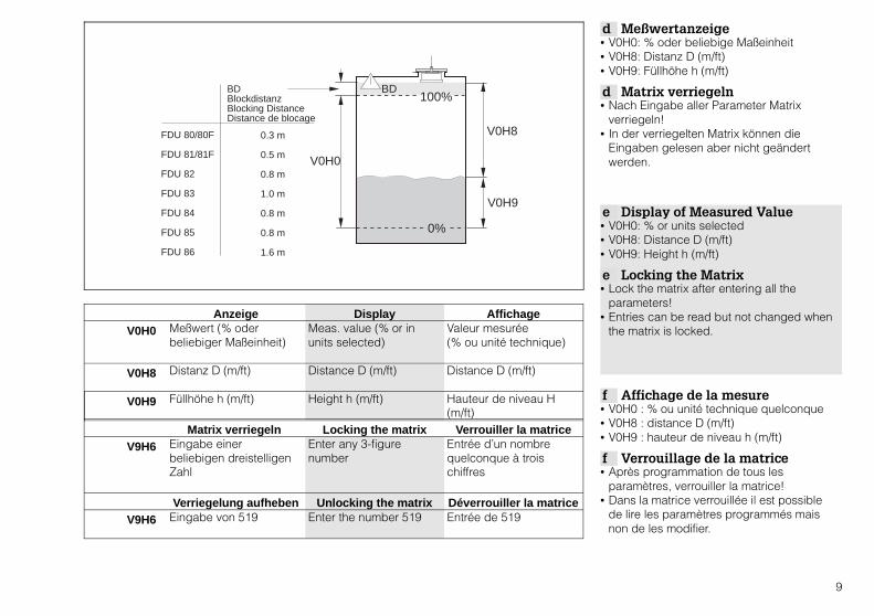
d Beispiel➀ Für einen stehenden zylindrischen Tank
soll der Meßwert (V0H0) in hlausgegeben werden.– 100 %: 350 hl
➁ Als Analogausgang wird 4…20 mAgewählt.– 15 hl: 4 mA– 350 hl: 20 mA– Bei Störungen soll der Stromausgang 110 % des Meßbereichs einnehmen.
f Exemple➀ Pour un réservoir cylindique vertical, la
mesure (V0H0) doit être donnée en hl– 100%: 350 hl
➁ Comme sortie analogique on choisit 4...20 mA– 15 hl: 4 mA– 350 hl: 20 mA– En cas de défaut la sortie courant doit être égale à 110 % de la gamme de mesure.
e Example➀ The measured value (V0H0) should be
given in hl for a vertical cylindrical tank– 100%: 350 hl
➁ A 4...20 mA signal is selected for the analogue output.– 15 hl: 4 mA– 350 hl: 20 mA– On error, the current output should assume 110% of the measuring range.
0 % 15 hl
100 % 350 hl
350 hl
h100 %
V2H7
Zeit / time / temps
4 mA
20 mA
110 %
15 hl
350 hl21,6 mA
➀
Eingabe Entry Entrée1. V2H7 350 350 3502. V2H0 0 0 0
➁
Eingabe Entry Entrée1. V8H1 1 1 12. V0H5 15 15 153. V0H6 350 350 3504. V3H4 1 1 1
14

d Relaisfunktion Grenzwert • FMU 860 hat 3 (1, 2, 5) wahlweise 5
Relais. Relais 5 ist die Funktion »Störrelais« zugeordnet.
• Diese Einstellungen weisen einem RelaisSchaltpunkte zu, die Grenzwerte bei der Befüllung des Behälters sind.
• Das »Grenzwertrelais« schaltet in Abhängigkeit des vorgegebenen Einschalt-und Ausschaltpunktes und bezieht sich aufden Meßwert in V0H0.
f Fonction relais seuil• Le FMU 860 possède 3 (1, 2, 5) ou 5 relais.
Au relais 5 est attribuée la fonction »relaisdéfaut«.
• Ces réglages attribuent à un relais despoints de commutation qui font office deseuils lors du remplissage du réservoir.
• Le relais de seuil commute en fonction despoints d’enclenchement et dedéclenchement.
e Relay Function Limit Value• FMU 860 has 3 (1, 2, 5) or 5 relays.
Relay 5 is allocated the »error relay«.• These settings assign switchpoints to a
relay, which are the limit values when fillingthe tank.
• The »limit value relay« responds to the preset switch on and switch off points andrefers to the measured value in V0H0.
Relaisbezeichnungen / Relay symbols / Etat des relaisArbeitszustand: angezogenOperating mode: energisedTravail: attiré
Ruhezustand: abgefallenStandby mode: de-energisedRepos: retombé
Eingabe Entry Entrée1. V1H0 Relais wählen
1: Relais 12: Relais 2
Select relay1: relay 12: relay 2
Choix relais 1: relais 12: relais 2
2. V1H1 Relaisfunktion wählen0: Grenzwert
Select relay function0: limit value
Fonction relais choisir 0: fonction »seuil«
3. V1H2 Einschaltpunktin Kundeneinheit
Switch on pointin customer units
Point d’enclenchementunité technique
4. V1H3 Ausschaltpunktin Kundeneinheit
Switch off pointin customer units
Point dedéclenchement unité technique
r u a
Relaisrelayrelais
LED
r u a
Relaisrelayrelais
LED
r u a
r u a
V1H3
V1H2
Füllstand / level / niveau
Rel
ais
/ rel
ay /
rela
is
V1H2V1H3
LED
LED
fallend / falling / descendant
steigend / rising /montant
fällt
ab
/ de-
ener
gise
s /
reto
mbe
zieh
t an
/ ene
rgis
es /
attir
é
BD
15
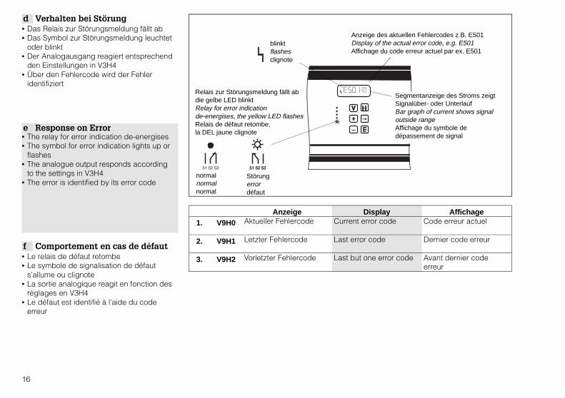
d Verhalten bei Störung• Das Relais zur Störungsmeldung fällt ab• Das Symbol zur Störungsmeldung leuchtet
oder blinkt• Der Analogausgang reagiert entsprechend
den Einstellungen in V3H4• Über den Fehlercode wird der Fehler
identifiziert
f Comportement en cas de défaut• Le relais de défaut retombe• Le symbole de signalisation de défaut
s’allume ou clignote• La sortie analogique reagit en fonction des
réglages en V3H4• Le défaut est identifié à l’aide du code
erreur
e Response on Error• The relay for error indication de-energises• The symbol for error indication lights up or
flashes• The analogue output responds according
to the settings in V3H4• The error is identified by its error code
Anzeige Display Affichage1. V9H0 Aktueller Fehlercode Current error code Code erreur actuel
2. V9H1 Letzter Fehlercode Last error code Dernier code erreur
3. V9H2 Vorletzter Fehlercode Last but one error code Avant dernier codeerreur
blinktflashesclignote
Relais zur Störungsmeldung fällt abdie gelbe LED blinktRelay for error indication de-energises, the yellow LED flashesRelais de défaut retombe, la DEL jaune clignote
normalnormalnormal
Anzeige des aktuellen Fehlercodes z.B. E501Display of the actual error code, e.g. E501Affichage du code erreur actuel par ex. E501
Segmentanzeige des Stroms zeigt Signalüber- oder UnterlaufBar graph of current shows signal outside rangeAffichage du symbole dedépassement de signal
Störungerrordéfaut
16

Diagnose / Maßnahme Error and remedy Erreurs et remèdesE501 Kein Sensortyp gewählt
In V0H4 Sensortypeingeben
No sensor type selected Enter sensor type inV0H4
Aucun type de sondesélectionné en V0H4. Entrer le type de sonde.
E613 Gerät in BetriebsartSimulation;in V8H0 Betriebsart 0wählen
Instrument in simulationmodeSelect mode 0 in V8H0
Appareil en modesimulation. Choisir enV8H0 un autre mode defonction.
E231 Kurzschluß internerTemperaturfühler;Sensoranschluß über-prüfen oder E+H-Service rufen
Short circuit of theinternal temperaturesensor;Check sensorconnection or call E+HService Centre
Court-circuit de la sondede température interne.Vérifier le raccordementde sonde ou contacterSAT E+H.
E641 Ultraschallecho kannnicht ausgewertetwerden; Fehler durch zuhohe Dämpfung (Stauboder Schaum);bleibt Fehler längerbestehenSensoranschlußüberprüfen oder E+H-Service rufen
Ultrasonic echo cannotbe evaluated. Error tueto excessive damping(dust or foam);The error remains checksensor connection orcall E+H Service Centre
Echos ne peuvent êtreexploités. Error due à unamortissement tropimportant (poussièresou mousse); si l’erreursubsiste, vérifier leraccordement de sondeou contacter le SAT E+H.Vérifier le raccordementde sonde ou contacterSAT E+H.
E661 Temperatur am Sensorzu hoch;Meßstelle überprüfen
Temperature at thesensor too high.Check measurementpoint
Température à la sondetrop élevée; vérifier lepoint de mesure
E111E112E113E114E115
ElektronischerGerätefehler.E+H-Service rufen
Electronic instrumenterror.Call E+H Service Centre
Défaut d’électronique;appeler le SAT E+H
d Fehlerdiagnose und MaßnahmeTreten außer den genanntenFehlermeldungen noch weitere auf oder läßtsich der Fehler nicht beheben, Angaben inder Betriebsanleitung BA100F beachten oderE+H-Kundendienst informieren.
f Erreurs et remèdesSi en plus du message erreur signalé il seproduit encore d’autres défauts ou si l’erreuren question ne peut être supprimée suivreles conseils donnés dans BA100F et eninformer le SAT E+H.
e Error and RemedyIf other error messages occur besides thosegiven or if the error cannot be remedied, thenrefer to information given in BA100F andcontact your E+H Service Centre.
17

FMU 860 H0 H1 H2 H3
V0def
Grundabgleich Meßkanal 1Calibration Channel 1Etalonnage de base voie 1
MeßwertMeasured valueValeur de mesure
Abgleich »Leer«Empty calibration Etalonnage »vide«
Abgleich »Voll«Full calibration Etalonnage »plein«
FüllstandanwendungLevel applicationType d’application
V1d
ef
Relais
RelaysRelais
Auswahl Relais
Relay selectionSélection relais
Relaisfunktion
Relay functionFonction relais
Einschaltpunkt
Switch-On pointPoint d’encl.
Ausschaltpunkt
Switch-Off pointPoint de décl.
V2def
Linearisierung Meßkanal 1Linearisation Channel 1Linéarisation voie 1
LinearisierungLinearisationLinéarisation
Ist-FüllhöheActual levelHauteur de rem-plissage réelle
Eingabe FüllhöheInput levelEntrée hauteur deniveau réelle
V3de
f
Echoparameter Meßkanal 1Echo parameters Channel 1
Paramètres échos voie 1
FestzielausblendungRange for automaticsuppressionSuppression deséchos fixes
EchodämpfungEcho attenuation
Atténuation de l’écho
S/N-VerhältnisSignal/noise ratio
Rapport signal/bruit
Wenn Echo fehltIf no echo
Perte d’écho
Zeilen 4, 5 und 6 nur bei FMU 862 / Rows 4, 5 and 6 for FMU 862 only / Lignes 4, 5 et 6 uniquement pour FMU 862
V7def
ServiceServiceService
ServiceServiceService
ServiceServiceService
ServiceServiceService
ServiceServiceService
V8
d
e
f
Betriebsparameter
Operating status
Paramètres de fonctionnement
Betriebsart
Operating mode
Mode defonctionnement
Stromausgänge
Select current
Sorties courant
4 mA-Schwelle
4 mA-threshold
Seuil 4 mA
Längeneinheit
Select distance unit
Unité de longueur
V9
d
e
f
Service und Simulation
Service and simulation
Service et simulation
Aktueller Fehlercode
Diagnostic code
Code erreur actuel
Letzter Fehlercode
Last diagnostic code
Dernier code erreur
Vorletzter Fehlercode
Last but one diagn.codeAvant-dernier code erreur
Geräte undSoftwareversionInstrument andsoftware versionVersion appareil et logiciel
Anzeigefeld / Output fields / Zone d’affichage
18

Eingabefeld / Entry fields / Zone d’entrée
H4 H5 H6 H7 H8 H9Sensortyp Type of sensorType sonde
Wert für 0/4 mAValue for 0/4 mAValeur pour 0/4 mA
Wert für 20 mAValue for 20 mAValeur pour 20 mA
IntegrationszeitOutput dampingTemps d’intégration
DistanzMeasured distanceDistance
FüllhöheMeasured levelHauteur de niveau
Alternierende Pumpensteuerungpump controlCommande de pompe alternée
Schaltverzögerung
Switch delayTemporisation
Eingabe VolumenInput volumeEntrée volume
ZeilennummerLine numberNuméro ligne
Durchmesser BehälterDiameter of vesselDiamètre cuve cyl. horiz.
Volumen BehälterVolume of vesselVolume cuve cyl. horiz.
Verhalten bei StörungSafety alarm
En cas d’alarme
HüllkurvenstatistikEnvelope statistics
Statistique de la courbe enveloppe
Zeilen 4, 5 und 6 nur bei FMU 862 / Rows 4, 5 and 6 for FMU 862 only / Lignes 4, 5 et 6 uniquement pour FMU 862ServiceServiceService
ServiceServiceService
ServiceServiceService
ServiceServiceService
ServiceServiceService
ServiceServiceService
Grenzwertschalter
Limit switch
Détecteurs externes
ExternerTemperaturfühlerExternal temperaturesensorSonde de temp. externe
General Reset 333
General reset 333
Reset général 333
Verriegelung
Security locking
Verrouillage
Simulation Füllstand
Simulation level
Simulation niveau
Simulation Volumen
Simulation volume
Simulation volume
Simulation Strom
Simulation current
Simulation courant
19

20

KA 017F/00/a6/05.00016085-0000Software 2.3
Hauser+EndressThe Power of Know How
ProsonicFMU 860
es Manual breve de instalación para la medición de nivel
i Manuale breve di installazióne per la misura di livello
nl Verkorte handleiding niveaumeting
-
V H
FMU 860
FDU
es Nota sobre seguridad
i Note sulla sicurezza
nl Veiligheidsinstructies
Atención• El montaje, la instalación eléctrica, la puesta en marcha, el mantenimiento y la utilización del
instrumento debe realizarse única y exclusivamente por personal cualificado , autorizado porel operario de la planta. El personal deberá leer y seguir atentamente las instruccionesindicadas en el presente manual breve de instalación, así como el manual de servicioBA 100F.
Nota• L’installazione, i collegamenti elettrici, la messa in esercizio, la manutenzione e l’utilizzo
di questo strumento deve essere effettuata esclusivamente da personale qualificato .Il personale dovrà leggere attentamente, capire e seguire le istruzioni fornite da questomanuale breve e dal manuale operativo BA 100F.
Kwalificatie• De montage, elektrische installatie, inbedrijfname, onderhoud en bediening van het
instrument alleen door gekwalificeerd personeel laten uitvoeren. Laat het personeel dezeverkorte handleiding en de inbedrijfnamevoorschriften BA 100F lezen en begrijpen en volgalle instructies hierin vermeld.
2

ENDRESS+HAUSERPROSONIC FMU 860
FMU860–R1A1 1
U: XX V AC+XX / XX/XX HZP: 15 VA
IP 66
Ser.No.: XXXXXXXXXXXPat.
NEMA 4X
Placa de identificaciónetichettatypeplaatje
es Identificación del instrumento• El presente manual breve de instalación
describe los ajustes más comunmenteempleados para la medición de nivel. Estotambién es aplicable a todos losinstrumentos que lleven la indicación FMU 860-R1A1 1.
• Para informaciónmás detallada sobre todaslas posibilidades e ajuste del ProsonicFMU 860…862 consultar el manual de puesta en servicio BA 100F.
i Identificazione dello strumento• Questo manuale breve descrive le più
importanti impostazioni per la misura dilivello con l’FMU 860.E’ riferito a tutti quegli strumenti chesull’etichetta di indentificazione riportano ilnumero di codice FMU860-R1A1 1.
• La descrizione di tutte le funzioni delProsonic FMU 860...862 è disponibile nelManuale Operativo BA100F.
nl Identificatie instrument• Deze verkorte handleiding beschrijft de
wezenlijke en meest voorkomendeinstellingen voor niveaumeting met deFMU 860. Deze geldt voor alle instrumentenwaarbij op het typeplaatje de codeFMU860-R1A1 1 is vermeld.
• Een volledig overzicht van alle functies vande instrumenten Prosonic FMU860...862 isopgenomen in de inbedrijfnamevoorschriftenBA100F.
FMU860-R1A1 1• versión estándar / versione standard / standaarduitvoering
• caja / custodia / behuizing
• teclado e indicador en parte frontal /tastiera e display sul frontalino /toetsen en display op het front
• tres relés / tre relè / drie relais
• Tensión de alimentación / alimentazione / voedingsspanning– A: 180…253 V, 50/60 Hz– B: 90…132 V, 50/60 Hz– C: 38…55 V, 50/60 Hz– D: 19…28 V, 50/60 Hz– E: 20…30 V (DC)
• sin protocolo de comunicación /nessun protocollo di comunicazione /zonder communicatieprotocol
3
es Conexión eléctrica • Antes de manipular el instrumento asegúrese de que esté desconectado de la fuente dealimentación.
• Verificar que la tensión de alimentación se corresponde con los valores indicados en laplaca de identificación.
• Al instalar el cable del sensor debe asegurarse que:– Las cajas de terminales intermedias pueden ser utilizadas con 300 mts de cable como máx.– La pantalla no debe estar conectada a tierra– La pantalla no debe sufrir ninguna rotura entre el sensor y el transmisor– FDU 83, 84, 85, 86: el cable de compensación de potencial no se encuentra en la pantalla.– Pantalla: filamentos de metal máx. 6 Ω– Especificaciones del cable (por hilo): máx. 6 Ω, máx 60 nF de capacidad total
• Si varios equipos Prosonic se encuentran instalados unos cerca de otros, deberán sersincronizados (ver BA 100F).
• Scollegare l’alimentazione prima di ogni intervento sullo strumento.• Accertarsi che la tensione di alimentazione equivalga a quella indicata sulla targhetta.• Installando il cavo del sensore assicurarsi che:
– per cavi di lunghezza fino a 300 m vengano utilizzate scatole di giunzione– le schermature non siano collegate a terra– a schermatura non presenti interruzione fra il sensore e il trasmettitore– FDU 83, 84, 85, 86: il cavo di compensazione di potenziale non deve essere all’interno della schermatura– schermatura: rete metallica max. 6 Ω– specifiche del cavo: max. 6 Ω per anima. max 60 nF come capacità totale
• Nel caso di utilizzo di più centraline Prosonic, queste vanno sincronizzante con l’opportunocollegamento (vds. BA 100F).
i Collegamenti elettrici
nl Elektrische aansluiting • Schakel altijd eerst de voedingsspanning uit voordat met werkzaamheden wordt begonnen.• Controleer of de voedingsspanning overeenkomt met die welke staat vermeld op het
typeplaatje.• Let bij het installeren van de sensorkabel op het volgende:
– Gebruik bij kabellengten tot 300 m een klemmenkast– Aard de afscherming niet– Trek de afscherming zonder elektrische onderbreking van de sensor naar de meetversterker– FDU 83, 84, 85, 86: kabel voor potentiaalvereffening niet binnen de afscherming leggen– Afscherming: gevlochten metaal max. 6 Ω– Kabelspecificatie (per ader): max. 6 Ω, max. 60 nF totale capaciteit
• Bij de aansluiting van meerdere Prosonic-instrumenten moeten de synchronisatie-aansluitingen verbonden worden (zie BA 100F).
4

FDU 80/80F/81/81F/82
BK YE RD
80 8182 80 8182
FDU 83/84/85/86
BKGNYE YE RD
80 8182
FDU 80/81
BN BU BKYE RD
80 8182
BKGNYE YERD
FDU 83/84/85/86
1 2 3 4 5
8011 21 31 41 51 6160 8112 22 32 42 52 62 8213 23 33 43 53 63 7064 71
L+ L-
L1 N l +1 l +2 YE RD
1 2 3 5 6 74
salida analógicacorrentestroom
relésrelèrelais
sensorsensoresensor
toma de tierramessa a terraaarde
alimentaciónalimentatorevoedingseenheid
toma de tierra dentro de la cajade terminalesmessa a terra alla scatola digiunzioneaarde aan klemmenkast
toma de tierra en el FMUmessa a terra all’FMUaarde aan FMU
con calefactorcon riscaldatoremet verwarming
pantallaschermaturaafscherming
5

es Indicador
i Display
nl Display
V H
➀ Señal de comunicación (sólo en versiones con protocolo decomunicación)
➁ Parámetro del campo enla matriz (parpadeadurante la programación)
➂ Campo de matriz
➃ Superación de la señalCorriente superior a 20 mA
➄ Gráfico de barras representando la señalanalógica
➅ Superación de la señal Corriente inferior a 0/4 mA
➆ Símbolo de indicación de erroriluminado: fallointermitencia: advertencia, el instrumento intenta continuar la medición
➀ ➁ ➂
➃➄➅
➆
➀ Segnale di comunicazione(solo per versioni conprotocollo dicomunicazione)
➁ Parametro della matriceoperativa (lampeggiaduranteil funzionamento)
➂ Campo di matrice
➃ Superamento del segnale.Corrente superiore a 20 mA
➄ Indicazione a barre delsegnale
➅ Superamento del segnale.Corrente inferiore a 0/4 mA
➆ Simbolo dell’indicazioned’errore.acceso: errorelampeggiante:avvertimento,lo strumento prova acontinuare ilfunzionamento
➀ Communicatiesignaal(alleen bij uitvoering metcommunicatieprotocol)
➁ Parameter van hetgeselecteerde matrixveld(knippert tijdens hetprogrammeren)
➂ Matrixveld
➃ Signaaloverschrijdingstroom groter dan 20 mA
➄ Balkdisplay stroomuitgang
➅ Signaalonderschrijdingstroom kleiner dan 0/4 mA
➆ Symbool voor storingbrandt: storingknippert: waarschuwing,het instrument probeertverder te meten
6

➀ Seleccionar el campo matriz con lasteclas V y H
• El parámetro del campo seleccionado,parpadea y puede ser cambiado
• Nota: El indicador cambia a V0H0 cuandose presionan simultáneamente las teclas Vy H
➁ Utilizar las teclas +, –, → para modificarlos parámetros
• Nota: El punto decimal se desplaza unaposición a la derecha cuando V y → sepresionan simultáneamente.
➂ Confirmar la programación presionando E
➀ Selezionare il campo di matrice tramite itasti V e H
• Il parametro nel campo selezionatolampeggia e può essere modificato
• Nota: Il display torna a V0H0 quando i tastiV e H vengono premuti simultaneamente
➁ Modificare il parametro usandoi tasti +, –, →
• Nota: Il punto decimale si sposta di unaposizione verso destra quando V e → vengono premuti simultaneamente
➂ Confermare la modifica premendo E
➀ Matrixveld kiezen met V en H• de parameter in het gekozen matrixveld
knippert en kan worden gewijzigd• opmerking: bij tegelijkertijd indrukken van V
en H verspringt het display naar V0H0
➁ Parameter wijzigen met +, – ,→ • Opmerking: bij tegelijkertijd indrukken van
V en → verspringt de decimale punt eenpositie naar rechts.
➂ Invoer bevestigen met Enter
V H
H
+ H
➀
V H
+
➁
E➂
es Funcionamiento• El FMU se programa mediante una matriz
10x10 campos (ver pág. 18/19)• A cada campo de matriz se le asigna una
función.
i Funzionamento• Il Prosonic FMU funziona attraverso una
matrice operativa di 10x10 campi(vds. pag. 18 e 19).
• Ad ogni campo di matrice è assegnata unafunzione.
nl Bediening• De FMU wordt met behulp van een 10x10
matrix bediend (zie blz. 18/19).• Aan ieder veld in de matrix is een bepaalde
functie toegekend.
7
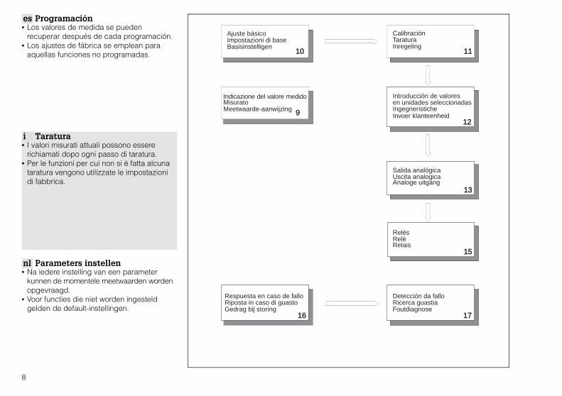
es Programación • Los valores de medida se pueden
recuperar después de cada programación.• Los ajustes de fábrica se emplean para
aquellas funciones no programadas.
i Taratura• I valori misurati attuali possono essere
richiamati dopo ogni passo di taratura.• Per le funzioni per cui non si è fatta alcuna
taratura vengono utilizzate le impostazionidi fabbrica.
nl Parameters instellen• Na iedere instelling van een parameter
kunnen de momentele meetwaarden wordenopgevraagd.
• Voor functies die niet worden ingesteldgelden de default-instellingen.
10
9
11
12
13
15
16 17
Ajuste básicoImpostazioni di baseBasisinstelligen
CalibraciónTaraturaInregeling
Meetwaarde-aanwijzingInvoer klanteenheid
Analoge uitgang
Relais
FoutdiagnoseGedrag bij storing
Introducción de valoresen unidades seleccionadasIngegneristiche
Indicazione del valore medidoMisurato
Salida analógicaUscita analogica
RelésRelè
Respuesta en caso de falloRiposta in caso di guasto
Detección da falloRicerca guastia
8

0%
100%BD
FDU 80/80F
FDU 81/81F
FDU 82
FDU 83
FDU 84
FDU 85
FDU 86
BDdistancia de bloqueodistanza di bloccoblokafstand
0.3 m
0.5 m
0.8 m
1.0 m
0.8 m
0.8 m
1.6 m
V0H0
V0H8
V0H9
Indicación Visualizzatore DisplayV0H0 Valor medido (% o en
unidades seleccionadas)Valore misurato (% onelle unità selezionate)
Meetwaarde (% ofwillekeurige eenheid)
V0H8 Distancia D (m/ft) Distanza D (m/ft) Afstand D (m/ft)
V0H9 Altura H (m/ft) Altezza h (m/ft) Niveauhoogte h (m/ft)
Bloqueo de la matriz Blocco della matrice Matrix vergrendelenV9H6 Teclear cualquier
número de 3 cifrasImmettere un qualsiasinumero di 3 cifre
Invoer van eenwillekeurig getal van3 cijfers
Desbloqueo de lamatriz
Sblocco della matrice Matrix vrijgeven
V9H6 Teclear el número 519 Immettere il numero 519 Invoer van 519
es Indicación del valor medido • V0H0: % o unidades seleccionadas• V0H8: Distancia D (m/ft)• V0H9: Altura H (m/ft)
es Bloqueo de la matriz• Bloquear la matriz después de introducir
todos los parámetros.• Los parámetros pueden visualizarse pero
no cambiarse cuando la matriz está bloqueada.
i Visualizzazione del valoremisurato
• V0H0: % o unità selezionate• V0H8: Distanza D (m/ft)• V0H9: Altezza h (m/ft)
i Blocco della matrice• Bloccare la matrice dopo aver immesso
tutti i parametri!• Le immissioni possono essere lette ma non
modificate se la matrice è bloccata.
nl Meetwaarde-aanwijzing• V0H0 meetwaarde: % of willekeurige
eenheid• V0H8 meetwaarde: afstand D (m/ft)• V0H9 meetwaarde: niveauhoogte h (m/ft)
nl Matrix vergrendelen• Na invoer van alle parameters de matrix
vergrendelen.• In de vergrendelde matrix kunnen de
waarden wel worden uitgelezen maar nietworden gewijzigd.
9

es Ajustes básicos• Realizar los ajustes durante la puesta en
marcha o bien cuando se reemplaza elsensor.
• Seleccionar los campos de matriz en el orden indicado a continuación, y programarlos parámetros en negrita (por ej. 333 para reset general).
• Activar »E« para validar la programación.• Nota: Las unidades de longitud sólo
deberán cambiarse inmediatamente después de un reset.
i Impostazioni di base• Effettuare queste impostazioni alla messa in
funzione o dopo aver sostituito il sensore.
• Richiamare i campi di matrice dalla tabellanell’esatta sequenza e scegliere i parametrida immettere (in grassetto per esempio 333per il reset generale).
• Registrare l’immissione con »E«
• Nota: Le unità di lunghezza (m, ft) possonoessere modificate solo immediatamentedopo il reset.
nl Basisinstellingen• Deze instellingen altijd uitvoeren bij de
inbedrijfname of bij het vervangen van desensor.
• Uit de tabel de juiste volgorde van dematrixvelden aflezen en de invoerparameter(vet afgedrukt bijv. 333 voor basisreset)kiezen.
• Invoer met E bevestigen.• Opgelet: lengte-eenheid alleen onmiddellijk
na een reset wijzigen.
E
HV
V
V
H
H
H V H
E––
+
1
3
2
Se ilumina o parpadea cuando realizan los ajustes básicosSi illumina o lampeggia durante le impostazioni di baseBrandt of knippert tijdens invoer basisinstellingen
Entrada Immissione Invoer1. V9H5 333: Reset 333: Reset 333: Basisreset
BUSY Visualizado en el indicador
Mostrato sul display Verschijnt op het display
2. V8H3 Unidades de altura0: m1: ft
Unità ingegneristiche:0: m1: ft
Lengte-eenheid kiezen0: m1: ft
3. V8H0 Modo de operación0: nivel del canal 1
Modalità operativa0: livello, canale 1
Bedrijfstype kiezen0: niveau kanaal 1
4. V0H4 Tipo de sensor 80: FDU 80, 81: FDU 8180F: FDU 80F81F: FDU 81F82: FDU 82, 83: FDU 8384: FDU 84, 85: FDU 8586: FDU 86
Tipo di sensore80: FDU 80, 81: FDU 8180F: FDU 80F81F: FDU 81F82: FDU 82, 83: FDU 8384: FDU 84, 85: FDU 8586: FDU 86
Type sensor80: FDU 80, 81: FDU 8180F: FDU 80F81F: FDU 81F82: FDU 82, 83: FDU 8384: FDU 84, 85: FDU 8586: FDU 86
10
0%
100%
EF
BD
aplicaciones de nivelapplicazioni per la misura di livelloniveautoepassingen
V0H30 1
2 3
4
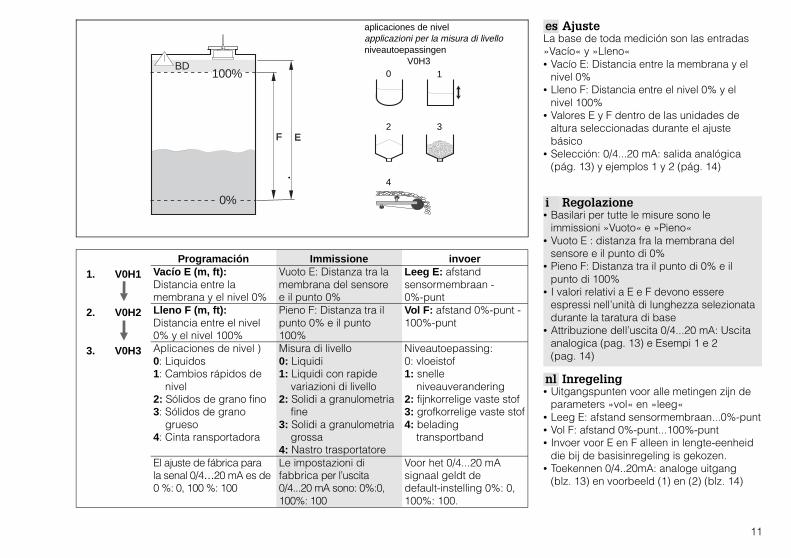
Programación Immissione invoer1. V0H1 Vacío E (m, ft):
Distancia entre lamembrana y el nivel 0%
Vuoto E: Distanza tra lamembrana del sensoree il punto 0%
Leeg E: afstandsensormembraan -0%-punt
2. V0H2 Lleno F (m, ft):Distancia entre el nivel0% y el nivel 100%
Pieno F: Distanza tra ilpunto 0% e il punto100%
Vol F: afstand 0%-punt -100%-punt
3. V0H3 Aplicaciones de nivel )0: Liquidos1: Cambios rápidos de nivel2: Sólidos de grano fino3: Sólidos de grano grueso4: Cinta ransportadora
Misura di livello0: Liquidi1: Liquidi con rapide variazioni di livello2: Solidi a granulometria fine3: Solidi a granulometria grossa4: Nastro trasportatore
Niveautoepassing:0: vloeistof1: snelle niveauverandering2: fijnkorrelige vaste stof3: grofkorrelige vaste stof4: belading transportband
El ajuste de fábrica parala senal 0/4…20 mA es de0 %: 0, 100 %: 100
Le impostazioni difabbrica per l’uscita0/4...20 mA sono: 0%:0,100%: 100
Voor het 0/4...20 mAsignaal geldt dedefault-instelling 0%: 0,100%: 100.
es AjusteLa base de toda medición son las entradas»Vacío« y »Lleno«• Vacío E: Distancia entre la membrana y el
nivel 0%• Lleno F: Distancia entre el nivel 0% y el
nivel 100%• Valores E y F dentro de las unidades de
altura seleccionadas durante el ajuste básico
• Selección: 0/4...20 mA: salida analógica (pág. 13) y ejemplos 1 y 2 (pág. 14)
i Regolazione• Basilari per tutte le misure sono le
immissioni »Vuoto« e »Pieno«• Vuoto E : distanza fra la membrana del
sensore e il punto di 0%• Pieno F: Distanza tra il punto di 0% e il
punto di 100%• I valori relativi a E e F devono essere
espressi nell’unità di lunghezza selezionatadurante la taratura di base
• Attribuzione dell’uscita 0/4...20 mA: Uscitaanalogica (pag. 13) e Esempi 1 e 2 (pag. 14)
nl Inregeling• Uitgangspunten voor alle metingen zijn de
parameters »vol« en »leeg«• Leeg E: afstand sensormembraan...0%-punt• Vol F: afstand 0%-punt...100%-punt• Invoer voor E en F alleen in lengte-eenheid
die bij de basisinregeling is gekozen.• Toekennen 0/4..20mA: analoge uitgang
(blz. 13) en voorbeeld (1) en (2) (blz. 14)
11
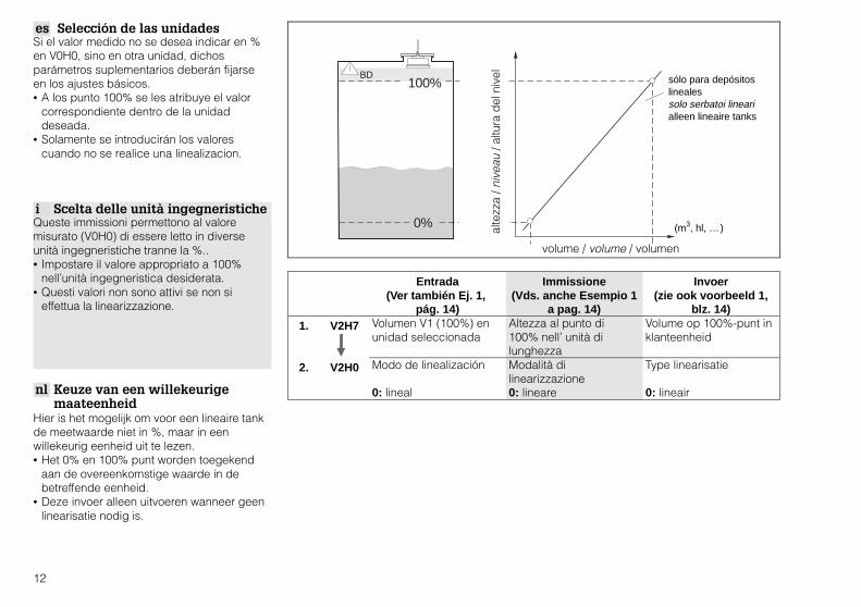
es Selección de las unidadesSi el valor medido no se desea indicar en %en V0H0, sino en otra unidad, dichosparámetros suplementarios deberán fijarseen los ajustes básicos.• A los punto 100% se les atribuye el valor
correspondiente dentro de la unidad deseada.
• Solamente se introducirán los valores cuando no se realice una linealizacion.
i Scelta delle unità ingegneristicheQueste immissioni permettono al valoremisurato (V0H0) di essere letto in diverseunità ingegneristiche tranne la %..• Impostare il valore appropriato a 100%
nell’unità ingegneristica desiderata.• Questi valori non sono attivi se non si
effettua la linearizzazione.
nl Keuze van een willekeurigemaateenheid
Hier is het mogelijk om voor een lineaire tankde meetwaarde niet in %, maar in eenwillekeurig eenheid uit te lezen.• Het 0% en 100% punt worden toegekend
aan de overeenkomstige waarde in debetreffende eenheid.
• Deze invoer alleen uitvoeren wanneer geenlinearisatie nodig is.
0%
100%BD
alte
zza
/ niv
eau
/ altu
ra d
el n
ivel
volume / volume / volumen
sólo para depósitoslinealessolo serbatoi linearialleen lineaire tanks
(m3, hl, … )
Entrada(Ver también Ej. 1,
pág. 14)
Immissione(Vds. anche Esempio 1
a pag. 14)
Invoer(zie ook voorbeeld 1,
blz. 14)1. V2H7 Volumen V1 (100%) en
unidad seleccionadaAltezza al punto di100% nell’ unità dilunghezza
Volume op 100%-punt inklanteenheid
2. V2H0 Modo de linealización
0: lineal
Modalità dilinearizzazione0: lineare
Type linearisatie
0: lineair
12

Uscita in caso di errore / gedrag bij storing /Indicación en caso de fallo
0: 0…20 mA 1: 4…20 mA
0: –10 % -2 mA -2,4 mA1: +110 % 22 mA 21,6 mA
V8H1V3H4
4 mA
20 mA
- 10 %
110 %
hold
4 mA
20 mA
0 % 100 %Valor medido/valore misurato /meetwaarde
tiempo / tempo / tijd
e Ajuste de la salida analógica• Los ajustes para la salida analógica
asignan una señal de corriente al valormedido– 0 ó 4 mA a 0%– 20 mA a 100%
• La corriente de salida puede fijarse demodo que el valor medido (V0H0) asumaun valor específico en caso de fallo.
• El símbolo de error se ilumina en caso defallo.
i Impostazione dell’uscitaanalogica
• L’impostazione dell’uscita analogicaassegna un segnale in corrente al valoremisurato– 0 o 4 mA al punto di 0%– 20 mA al punto di 100%
• L’uscita in corrente può essere impostatacosì che il valore misurato (V0H0) assumaun valore specifico in caso di errore.
• Il simbolo dell’errore si accende in caso dierrore.
nl Analoge uitgang instellen• De instellingen voor de analoge uitgang
kennen de meetwaarde toe aan eenstroomsignaal– de waarde 0/4 mA aan het 0%-punt– de waarde 20 mA aan het 100%-punt
• De stroomuitgang kan zo worden ingestelddat de meetwaarde (V0H0) bij storingeneen bepaalde waarde aanneemt.
• Bij storingen brandt het symbool voorfoutmelding.
Programación(Ver también ej.1 y 2,
pág. 14
Immissione(Vds. anche Esempio 1
e 2 a pag. 14)
Invoer(zie ook voorbeeld 1 en
2 blz. 14)1. V8H1 Selección de la
corriente de salida0: 0...20 mA1: 4...20 mA
Scelta dell’uscita incorrente0: 0...20 mA1: 4...20 mA
Stroomuitgang kiezen
0: 0...20 mA1: 4...20 mA
2. V0H5 Valor 4 mA Valore 4 mA 4 mA-waarde
3. V0H6 Valor 20 mA Valore 20 mA 20 mA-waarde
4. V3H4Indicador coninterferencias0: -10 % del rango de medida1: 110% del rango de medida2: Mantiene el último valor medido
Uscita in caso di errore0: -10% del campo dimisura1: 110% del campomisurato2: Mantiene l’ultimovalore misurato
Aanwijzing bij storing0: -10% van hetmeetbereik1: 110% van hetmeetbereik2: laatste meetwaardevasthouden
13

es Ejemplo➀ En el caso de un depósito cilíndrico
vertical, el valor medido (V0H0) deberádarse en hl.– 100%: 350 hl
➁ Como salida analógica se seleccionauna señal 4..20 mA– 15 hl: 4 mA– 350 hl: 20 mA– En caso de fallo, la corriente de salida deberá asumir el 110% del rango de medición.
i Esempio➀ Il valore misurato (V0H0) può essere
espresso in hl per un serbatoio a cilindroverticale.– 100%: 350 hl
➁ Un segnale 4...20 mA è impostato perl’uscita analogica– 15 hl: 4 mA;– 350 hl: 20 mA– In caso d’errore, l’uscita in corrente dovrebbe assumere il 110% del campo di misura.
nl Voorbeeld➀ Voor een verticale cilindrische tank moet
de meetwaarde (V0H0) worden gegevenin hl.– 100%: 350 hl
➁ Als analoge uitgang wordt 4...20 mAgekozen.– 15 hl: 4 mA;– 350 hl: 20 mA– Bij storingen moet de stroomuitgang een waarde 110% van het meetbereik aannemen.
➀
➁
0 % 15 hl
100 % 350 hl
350 hl
h100 %
V2H7
4 mA
20 mA
110 %
15 hl
350 hl21,6 mA
Tiempo / tempo / tijd
Entrada Immissione Invoer1. V2H7 350 350 3502. V2H0 0 0 0
Entrada Immissione Invoer1. V8H1 1 1 12. V0H5 15 15 153. V0H6 350 350 3504. V3H4 1 1 1
14
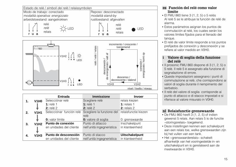
Entrada Immissione Invoer1. V1H0 Selecciónar relé
1: relé 12: relé 2
Scegliere relè1: relè 12: relè 2
relais kiezen1: relais 12: relais 2
2. V1H1 Selecciónar función relé
0: valor límite
Scegliere la funzione delrelè0: valore di soglia
relaisfunctie kiezen
0: grenswaarde3. V1H2 Punto de conexión
en unidades del clientePunto di attacconell’unità ingegneristica
Inschakelpuntin klanteenheid
4. V1H3 Punto de desconexiónen unidades del cliente
Punto di stacconell’unità ingegneristica
Uitschakelpuntin klanteenheid
es Función del relé como valorlímite
• El FMU 860 tiene 3 (1, 2, 5) o 5 relésAl relé 5 se le atribuye la función de relé dealarma.
• Estos parámetros asignan los puntos deconmutación al relé, los cuales serán losvalores límites fijados para el llenado deltanque.
• El relé de valor límite responde a los puntosprefijados de conexión y desconexión y serefiere al valor medido en V0H0.
i Valore di soglia della funzionedel relè
• Il prosonic FMU 860 dispone di 3 (1, 2, 5) o5 relè. Il relè 5 è assegnato alla funzione disegnalazione di errore.
• Queste impostazioni assegnano i punti dicommutazione ai relè, che corrispondono aivalori di soglia durante il riempimento delserbatoio.
• Il relè del valore di soglia corrisponde aipunto di attacco e di stacco impostati e siriferisce al valore misurato in V0H0.
nl Relaisfunctie grenswaarde• De FMU 860 heeft 3 (1, 2, 5) of indien
gewenst 5 relais. Aan relais 5 is de functie»storingsrelais« toegekend.
• Deze instellingen kennen een schakelpuntaan een relais toe, welke grenswaarden zijnbij het vullen van een tank.
• Het »grenswaarderelais« schakeltafhankelijk van het vooringestelde in- enuitschakelpunt en is gerelateerd aan demeetwaarde in V0H0.
Estado de relé / simboli dei relè / relaissymbolenModo de trabajo: conectadomodalità operativa: energizzatoarbeidstoestand: aangetrokken
Reposo: desconectadomodalità stand-byrusttoestand: afgevallen
r u a
r u a
V1H3
V1H2
V1H2V1H3
LED
LED
BD
cone
xión
/en
ergi
zzat
o / k
omt o
p
desc
onex
ión
/ de
-ene
rgiz
zato
/ va
lt af
relé
/ re
lè /
rela
is
descenso /decrescente / dalend
incremento / crescente / toenemend
nivel / livello / niveau
r u a
relérelèrelais
LED
r u a
relérelèrelais
LED
15

es Respuesta en caso de fallo• El relé de indicación de fallo se desconecta.• El símbolo de indicación de fallo se ilumina
o parpadea.• La salida analógica responde de acuerdo
con los ajustes en V3H4.• El fallo se identifica por el código de fallo.
i Risposta in caso di errore• Il relè per l’indicazione d’errore viene
de-energizzato.• Il simbolo per l’indicazione d’errore si
accende o inizia a lampeggiare.• L’uscita analogica si comporta secondo
quanto impostato in V3H4.• L’errore viene identificato mediante un
codice d’errore.
nl Gedrag bij storing• Het relais voor storingsmelding valt af.• Het symbool voor storingsmelding knippert
of brandt.• De analoge uitgang reageert
overeenkomstig de instellingen in V3H4.• Door middel van de foutcode wordt de
storing geïdentificeerd.
Indicación Display Display1. V9H0 Código de fallo actual Codice d’errore attuale momentele foutcode
2. V9H1 Último código de fallo Ultimo codice d’errore laatste foutcode
3. V9H2 Penúltimo código de fallo Penultimo codice d’errore voorlaatste foutcode
parpadealampeggiaknippert
el relé de fallo se desconecta, el LEDamarillo se iluminail relè per l’indicazione d’errore vienede-energizzato, il LED giallo lampeggiarelais voor storingsmelding valt af, degele LED knippert
normalnormalenormaal
indicación del código de errordisplay dell’attuale codice d’errore, es. E501anwijzing momentele foutcode bijv. E501
el gráfico de barras de la corrientemuestra la senal fuera de rangol’indicazione a barre della corrente vafuori campobalkaanwijzing stroom toontsignaalover- of onderschrijding
falloerrorestoring
16

Códigos de error y sucorrección
Errore e rimedio Diagnose/maatregel
E501 No se ha especificadoel tipo de sensor;entrar tipo de sensor enV0H4
Nessun tipo di sensoreselezionato;immettere il tipo disensore in V0H4.
Geen sensortypegekozen;in V0H4 sensortypeinvoeren.
E613 Instrumento en modo desimulación; seleccioneotra modalidadoperativa en V8H0
Strumento in modalità disimulazione;selezionare la modalità0 in V8H0.
Instrument insimulatiefunctie;in V8H0 functie 0 kiezen.
E231 Cortocircuito en elsensor de temperaturainterno; compruebe laconexión del sensor obien contacte con elservicio técnico de E+H
Corto circuito del sensoredi temperatura integrato;.verificare il collegamentodel sensore o chiamare ilServizio Assistenza E+H
Kortsluiting internetemperatuursensor;sensoraansluitingcontroleren of contactopnemen met E+Hservice-afdeling
E641 El eco ultrasónico nopuede ser evaluado;compruebe la conexióndel sensor o biencontacte con el serviciotécnico de E+H
L’eco ultrasonoro nonviene valutato. Erroredovuto ad un eccessivosmorzamento (polvere oschiuma);se l’errore permaneverificare ilcollegamento delsensore o chiamare ilServizio Assistenza E+H
Ultrasone echo kan nietworden verwerkt; foutdoor te hoge demping(stof of schuim); blijft destoring langer bestaancontroleer dan desensoraansluiting ofneem contact op metE+H service-afdeling
E661 Temperatura en elsensor demasiado alta;compruebe el punto demedición
Temperatura al sensoretroppo elevata;verificare il punto dimisura
Temperatuur aan desensor te hoog;controleer de meting
E111E112E113E114E115
Error electrónico en launidad; contacte con elservicio técnico de E+H
Errore nell’elettronicadello strumento;chiamare il ServizioAssistenza E+H
Elektronische instrumentfout; contact opnemenmet E+H service-afdeling
es Códigos de error y su correcciónEn caso de requerir más amplia informaciónsobre la detección de averías, consulte elmanual de instrucciones BA 100F o bien contacte con nuestro servicio técnico.
i Errori e rimediSe si verificano errori con codice diverso daquelli forniti, oppure se permangono, fareriferimento al Manuale Operativo BA 100F econtattare il Servizio Assistenza E+H.
nl Foutdiagnose en maatregelenWanneer een foutmelding optreedt die nietis genoemd of kan de fout niet wordenopgeheven zie dan deinbedrijfstellingsvoorschriften BA 100F ofneem contact op met de E+H service-afdeling.
17

FMU 860
H0 H1 H2 H3
V0esinl
Calibración del canal 1Taratura del canale 1Basisinregeling kanaal 1
Valor medidoValore misuratoMeetwaarde
Calibrado en ”vacío”Taratura di vuotoInregeling »leeg«
Calibrado en ”lleno”Taratura di pienoInregeling »vol«
Aplicación de nivelTipo di applicazioneNiveautoepassing
V1es
i
nl
Relé
Relè
Relais
Selección de relé
Scelta del relè
Relaiskeuze
Función de relé
Funzione del relè
Relaisfunctie
Punto de conexión
Punto di attacco
Inschakelpunt
Punto de desconexión
Punto di stacco
Uitschakelpunt
V2es
inl
Linealización del Canal 1
Linearizzazione canale 1Linearisatie kanaal 1
Linealización
Tipo di linearizzazioneLinearisatie
Nivel actual
Valore attualeMomenteel niveau
Programación devolumen de llenadoImmissione livelloInvoer niveau
V3es
i
nl
Parámetro de eco canal 1
Parametri eco canale 1
Echoparameter kanaal 1
Rango para supresiónautomáticaCampo per lasoppressioneautomaticaStoorecho-onderdrukking
Atenuación del eco
Attenuazione dell’eco
Echodemping
Relación señal/ruido
Rapporto Segnale/disturbo
Signaal-ruisverhouding
Si no hay eco
Nessun eco
Gedrag indien echoontbreekt
Filas 4,5 y 6 únicamente para FMU 862 / Righe 4, 5 e 6 solo per FMU 862 / Regels 4, 5 en 6 alleen bij FMU 862
V7esinl
ServicioServiceService
ServicioServiceService
ServicioServiceService
ServicioServiceService
ServicioServiceService
V8
es
i
nl
Estatus operativo
Stato operativo
Bedrijfsparameter
Modo operativo
Modalità operativa
Bedrijfsfunctie
Selección de corriente
Scelta corrente
Analoge uitgangen
Umbral 4 mA
Soglia 4 mA
4mA drempel
Seleccionar unidaddistanciaScelta unità dilunghezzaLengte-eenheid
V9
es
i
nl
Servicio y simulación
Servizio e simulazione
Service en simulatie
Código de diagnóstico
Codice di diagnosi
Momentele foutcode
Último código dediagnósticoUltimo codice didiagnosiLaatste foutcode
Penúltimo código dediagnósticoPenultimo codice didiagnosiVoorlaatste foutcode
Equipo y versión desoftwareStrumento e versionesoftwareInstrument ensoftware-versie
Campos de lectura / Campi di lettura / Aanwijzing-veld
18

H4 H5 H6 H7 H8 H9Tipo de sensorTipo di sensoreSensortype
Valor para 0/4 mAValore per 0/4 mAWaarde voor 0/4 mA
Valor para 20 mAValore per 20 mAWaarde voor 20 mA
Tiempo de integraciónSmorzamento uscitaIntegratietijd
DistanciaDistanza misurataAfstand
Nivel medidoLivello misuratoNiveau
Control alternativo debombaControllo delle pompeAlternerendepompsturing
Retraso conexión
Ritardi di intervento
SchakelvertragingEntrar volumen
Immissione volumeInvoer volume
Nº línea
Numero della lineaSteunpuntnummer
Diámetro depósito
Diametro del serbatoioTankdiamter
Volumen depósito
Volume del serbatoioTankvolume
Alarma seguridad
Allarme di sicurezza
Gedrag bij storing
Estadística envolvente
Statistica della curvadi inviluppo
StoorechofilterFilas 4,5 y 6 únicamente para FMU 862 / Righe 4, 5 e 6 solo per FMU 862 / Regels 4, 5 en 6 alleen bij FMU 862
ServicioServiceService
ServicioServiceService
ServicioServiceService
ServicioServiceService
ServicioServiceService
ServicioServiceService
Interruptor límite
Contatto di soglia
Grenswaarde-schakelaar
Sensor detemperatura externoSensore esterno ditemperaturaExternetemperatuursensor
Reposción general333Reset generale 333
Algemene reset 333
Bloqueo de seguridad
Blocco di sicurezza
Vergrendeling
Simulación nivel
Simulazione di livello
Simulatie niveau
Simulación volumen
Simulazione delvolumeSimulatie volume
Simulación corriente
Simulazione dellacorrenteSimulatie stroom
Programación de campos / Campi di immissione / Programmeerveld
19

AustriaEndress+Hauser Ges.m.b.H.WienTel. (01) 88056-0, Fax (01) 88056-35
Belgium / LuxembourgEndress+Hauser N.V.BrusselsTel. (02) 2480600, Fax (02) 2480553
CanadaEndress+Hauser Ltd.Burlington, OntarioTel. (905) 6819292, Fax (905) 6819444
DenmarkEndress+Hauser A/SS@248borgTel. (70) 131132, Fax (70) 132133
FinlandEndress+Hauser OyEspooTel. (09) 8676740, Fax (09) 86767440
FranceEndress+HauserHuningue Tel. (389) 696768, Fax (389) 694802
GermanyEndress+Hauser Messtechnik GmbH+Co.Weil am RheinTel. (07621) 97501, Fax (07621) 975555
Great BritainEndress+Hauser Ltd.ManchesterTel. (0161) 2865000, Fax (0161) 9981841
Hong KongEndress+Hauser (H.K.) Ltd.Hong KongTel. 25283120, Fax 28654171
ItalyEndress+Hauser Italia S.p.A.Cernusco s/N MilanoTel. (02) 921 92 1921, Fax (02) 92107153
JapanSakura Endress Co., Ltd.TokyoTel. (0422) 540613, Fax (0422) 550275
MalaysiaEndress+Hauser (M) Sdn. Bhd.Petaling Jaya, Selangor Darul EhsanTel. (03) 7334848, Fax (03) 7338800
NetherlandEndress+Hauser B.V.NaardenTel. (035) 6958611, Fax (035) 6958825
NorwayEndress+Hauser A/STranbyTel. (032) 859850, Fax (032) 859851
SingaporeEndress+Hauser (S.E.A.) Pte., Ltd.SingaporeTel. 5668222, Fax 5666848
South AfricaEndress+Hauser Pty. Ltd.SandtonTel. (011) 4441386, Fax (011) 4441977
SpainEndress+Hauser S.A.Sant Just DesvernTel. (93) 4803366, Fax (93) 4733839
SwedenEndress+Hauser ABSollentunaTel. (08) 55511600, Fax (08) 55511655
SwitzerlandEndress+Hauser AGReinach/BL 1Tel. (061) 7157575, Fax (061) 7111650
ThailandEndress+Hauser Ltd.BangkokTel. (2) 9967811-20, Fax (2) 9967810
USAEndress+Hauser Inc.Greenwood, IndianaTel. (317) 535-7138, Fax (317) 535-8498
InternationalEndress+Hauser GmbH+Co.Instruments InternationalWeil am RheinTel. (07621) 97502, Fax (07621) 975345
http://www.endress.com
04.00/PTS-D
016085-0000
KA 017F/00/a6/05.00, 016085-0000, RÜ/CV4.2
Related Documents