Proposed torque optimized behavior for digital speed control of induction motors H.M.B. Metwally a, * , F.E. Abdel-Kader b , H.M. El-Shewy a , M.M. El-Kholy a a Department of Electrical Engineering, Faculty of Engineering, Zagazig University, Zagazig, Egypt b Department of Electrical Engineering, Faculty of Engineering, Menoufyia University, Menoufyia, Egypt Received 29 January 2001; accepted 15 June 2001 Abstract In this paper, a control strategy for speed control of induction motors with field orientation is proposed. The proposed method adjusts the output voltage and frequency of the converter to operate the motor at the desired speed with maximum torque per ampere at all load torques keeping the torque angle equal to 90°.A comparison between the performance characteristics of a 2 hp induction motor using three methods of speed control is presented. These methods are the proposed method, the direct torque control method and the constant V =f method. The comparison showed that better performance characteristics are obtained using the proposed speed control strategy. A computer program, based on this method, is developed. Starting from the motor parameters, the program calculates a data set for the stator voltage and frequency required to obtaining maximum torque per ampere at any motor speed and load torque. This data set can be used by the digital speed control system of induction motors. Ó 2002 Published by Elsevier Science Ltd. Keywords: Electrical drives; Digital speed control; Field orientation control 1. Introduction Market analysis shows that most industrial applications use induction motors. The reasons for this include robustness, reliability, low price and high efficiency. However, the use of induction motors has its disadvantages. These lie mostly in the difficult controllability due to its complex mathematical model, the nonlinear behavior during saturation and the electrical parameters Energy Conversion and Management 43 (2002) 1675–1688 www.elsevier.com/locate/enconman * Corresponding author. Tel.: +20-55-622-411; fax: +20-55-324-987. E-mail address: [email protected] (H.M.B. Metwally). 0196-8904/02/$ - see front matter Ó 2002 Published by Elsevier Science Ltd. PII:S0196-8904(01)00123-6

Welcome message from author
This document is posted to help you gain knowledge. Please leave a comment to let me know what you think about it! Share it to your friends and learn new things together.
Transcript
Proposed torque optimized behavior for digital speedcontrol of induction motors
H.M.B. Metwally a,*, F.E. Abdel-Kader b, H.M. El-Shewy a, M.M. El-Kholy a
a Department of Electrical Engineering, Faculty of Engineering, Zagazig University, Zagazig, Egyptb Department of Electrical Engineering, Faculty of Engineering, Menoufyia University, Menoufyia, Egypt
Received 29 January 2001; accepted 15 June 2001
Abstract
In this paper, a control strategy for speed control of induction motors with field orientation is proposed.The proposed method adjusts the output voltage and frequency of the converter to operate the motor at thedesired speed with maximum torque per ampere at all load torques keeping the torque angle equal to 90�. Acomparison between the performance characteristics of a 2 hp induction motor using three methods ofspeed control is presented. These methods are the proposed method, the direct torque control method andthe constant V =f method. The comparison showed that better performance characteristics are obtainedusing the proposed speed control strategy. A computer program, based on this method, is developed.Starting from the motor parameters, the program calculates a data set for the stator voltage and frequencyrequired to obtaining maximum torque per ampere at any motor speed and load torque. This data set canbe used by the digital speed control system of induction motors. � 2002 Published by Elsevier Science Ltd.
Keywords: Electrical drives; Digital speed control; Field orientation control
1. Introduction
Market analysis shows that most industrial applications use induction motors. The reasons forthis include robustness, reliability, low price and high efficiency. However, the use of inductionmotors has its disadvantages. These lie mostly in the difficult controllability due to its complexmathematical model, the nonlinear behavior during saturation and the electrical parameters
Energy Conversion and Management 43 (2002) 1675–1688www.elsevier.com/locate/enconman
*Corresponding author. Tel.: +20-55-622-411; fax: +20-55-324-987.
E-mail address: [email protected] (H.M.B. Metwally).
0196-8904/02/$ - see front matter � 2002 Published by Elsevier Science Ltd.
PII: S0196-8904(01)00123-6
variation, which depends on the physical influence of the temperature. Conventionally, the motorcontroller is designed with analog components because they are simple and inexpensive. However,there are several drawbacks with analog systems. Aging and temperature can bring about com-ponent variations, causing the system to need regular adjustment. Also, as the number of partsincreases, the reliability of the system decreases. Analog components raise tolerance issues, andupgrades are difficult because the design is hardwired.Digital systems, on the other hand, offer advantages over analog designs. Drift is eliminated
because most functions are performed digitally, upgrades can easily be made in software and thenumber of parts is also reduced, since digital systems can handle several functions in one chip.Digital signal processors go on further to provide high speed, high resolution and sensorless al-gorithms, which reduce system cost. There are several methods to control induction motor torqueand speed. These methods can be categorized into two groups: the scalar and the vector controlmethods.Scalar control means that variables are controlled only in magnitude, and the feedback com-
mand signals are proportional to dc quantities. A scalar control method can only drive the statorfrequency using a voltage or a current as a command. Among the scalar methods known is theone that assumes, by varying the stator voltage in proportion to frequency, the torque iskept constant. This control technique is simple, easy and fast to program and requires only afew calculation capabilities. The drawbacks are very poor reaction time for load changes andlow efficiency. This technology is adequate for steady state conditions or for loads suchas pumps and fans, that can tolerate extended time periods for speed changes, but many appli-cations require abrupt and accurate changes in load and speed and are better served by vectordrives.In vector control, the variables are controlled in magnitude and phase angle. This method takes
into consideration not only successive steady states but real mathematical equations that describethe motor itself. The control results obtained have better dynamic response for torque variationsin a wider speed range. This technique of control needs more calculations than the standard V =fcontrol scheme. This can be made by using a calculation unit included in a digital signal processor.The speed and power factor (PF) are controlled in order to optimize the operation of the ad-justable speed drive. This is accomplished by means of a variable voltage, variable frequencyconverter. This controller provides online control of rotor speed and power factor. The powerconverter control unit must calculate the voltage, the PF and the optimal operation characteristic[1]. The transfer function representation of a variable frequency fed induction motor based on alinear mathematical model is presented by Salama and Holmes [2]. The effect of magnetic fluxsaturation on the performance of a current regulated, field oriented induction motor drive inanalytical form has been reported in Ref. [3]. An adaptive speed controller that can estimate loadtorque for induction motor drives employing a transputer based parallel processing technique hasbeen proposed in Ref. [4]. A minimizing of stator current amplitude for a given load torque ispresented in Ref. [5]. In this paper, a simple control strategy is proposed, which has a straight-forward goal of digital speed control of an induction motor with field oriented control formaximum torque per ampere. In this method, the motor voltage and frequency are adjusted tominimize the stator current for a given load torque and desired speed. The method is used toprepare the stator voltage and frequency data for digital speed control systems of inductionmotors.
1676 H.M.B. Metwally et al. / Energy Conversion and Management 43 (2002) 1675–1688
2. Mathematical model
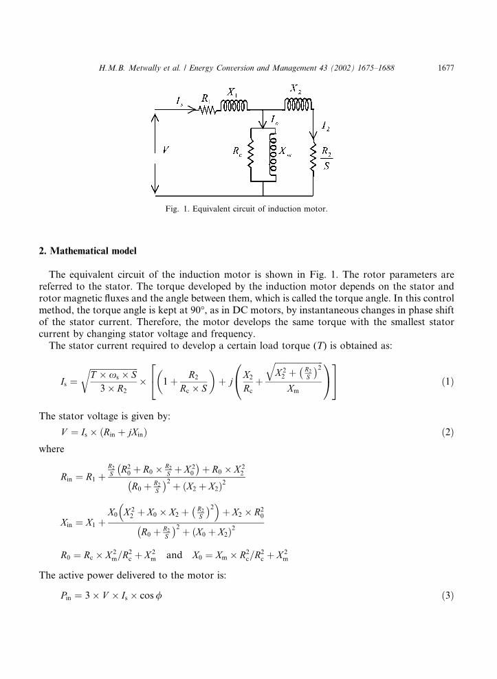
The equivalent circuit of the induction motor is shown in Fig. 1. The rotor parameters arereferred to the stator. The torque developed by the induction motor depends on the stator androtor magnetic fluxes and the angle between them, which is called the torque angle. In this controlmethod, the torque angle is kept at 90�, as in DC motors, by instantaneous changes in phase shiftof the stator current. Therefore, the motor develops the same torque with the smallest statorcurrent by changing stator voltage and frequency.The stator current required to develop a certain load torque (T) is obtained as:
Is ¼ffiffiffiffiffiffiffiffiffiffiffiffiffiffiffiffiffiffiffiffiffiffiffiT � xs � S3� R2
r� 1
�24 þ R2Rc � S
�þ j
X2Rc
0@ þ
ffiffiffiffiffiffiffiffiffiffiffiffiffiffiffiffiffiffiffiffiffiffiffiX 22 þ R2
S
2qXm
1A35 ð1Þ
The stator voltage is given by:
V ¼ Is � ðRin þ jXinÞ ð2Þwhere
Rin ¼ R1 þR2S R20 þ R0 � R2
S þ X 20
þ R0 � X 2
2
R0 þ R2S
2 þ ðX2 þ X2Þ2
Xin ¼ X1 þX0 X 2
2 þ X0 � X2 þ R2S
2� �þ X2 � R20
R0 þ R2S
2 þ X0 þ X2ð Þ2
R0 ¼ Rc � X 2m=R
2c þ X 2
m and X0 ¼ Xm � R2c=R2c þ X 2
m
The active power delivered to the motor is:
Pin ¼ 3� V � Is � cos/ ð3Þ
Fig. 1. Equivalent circuit of induction motor.
H.M.B. Metwally et al. / Energy Conversion and Management 43 (2002) 1675–1688 1677
The motor efficiency (g) and PF are obtained as:
g ¼ T � xs � ð1� SÞPin
ð4Þ
PF ¼ RinffiffiffiffiffiffiffiffiffiffiffiffiffiffiffiffiffiffiR2in þ X 2
in
p ð5Þ
The above analysis is used to determine the suitable stator voltage and frequency to run theinduction motor at a given speed and load torque. Eq. (2) determines the required stator voltage.This voltage depends on the load torque and slip. A desired speed, at a given load torque, can beobtained with different values of stator voltage and frequency. A computer program is developedto determine the optimum values. To show the importance of this method of speed control, acomparison with two other methods is performed. These methods are the constant V =f methodand the direct torque control (DTC) method.
2.1. Direct torque control strategy
In this control method, the magnetizing component and the torque component of the statorcurrent are varied to give minimum stator current at a given speed and load torque. The statorcurrent in this case is given by:
Is ¼ffiffiffiffiffiffiffiffiffiffiffiffiffiffiffiffiffiffiffiffiffiffiffiT � xs � S3� R2
r� 1
��þ R2Rc � S
þ X2Xm
�þ j
X2Rc
�� R2Xm � S
��ð6Þ
The stator voltage is given by Eq. (2). A computer program is constructed up to compute theoptimum values of stator voltage and frequency to run the motor at any desired speed withminimum stator current at a given load torque.
2.2. V =f control strategy
Operation at any desired speed and load torque can be obtained by varying both the statorvoltage and frequency, keeping the ratio V =f constant, to have rated flux at all speeds and tor-ques. Eq. (2)–(6) are used, with the constraint V =f ¼ constant, to calculate the performancecharacteristics of the motor under this mode of operation.
3. Results
The following results show the performance characteristics of induction motors which run atconstant speed.
3.1. V =f control srategy
The stator voltage and frequency are varied subject to the constraint V =f ¼ constant to obtainthe desired speed at different loads. Figs. 2–6 show the variations of stator frequency, stator
1678 H.M.B. Metwally et al. / Energy Conversion and Management 43 (2002) 1675–1688
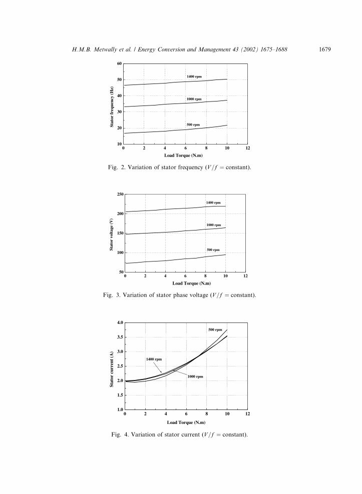
Fig. 2. Variation of stator frequency (V =f ¼ constant).
Fig. 3. Variation of stator phase voltage (V =f ¼ constant).
Fig. 4. Variation of stator current (V =f ¼ constant).
H.M.B. Metwally et al. / Energy Conversion and Management 43 (2002) 1675–1688 1679
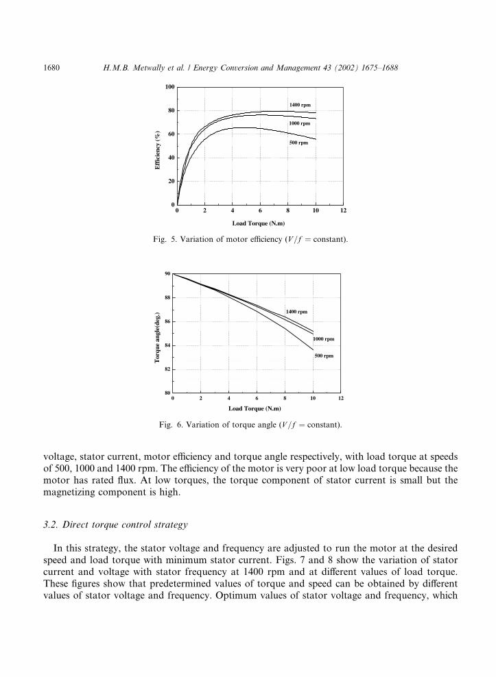
voltage, stator current, motor efficiency and torque angle respectively, with load torque at speedsof 500, 1000 and 1400 rpm. The efficiency of the motor is very poor at low load torque because themotor has rated flux. At low torques, the torque component of stator current is small but themagnetizing component is high.
3.2. Direct torque control strategy
In this strategy, the stator voltage and frequency are adjusted to run the motor at the desiredspeed and load torque with minimum stator current. Figs. 7 and 8 show the variation of statorcurrent and voltage with stator frequency at 1400 rpm and at different values of load torque.These figures show that predetermined values of torque and speed can be obtained by differentvalues of stator voltage and frequency. Optimum values of stator voltage and frequency, which
Fig. 5. Variation of motor efficiency (V =f ¼ constant).
Fig. 6. Variation of torque angle (V =f ¼ constant).
1680 H.M.B. Metwally et al. / Energy Conversion and Management 43 (2002) 1675–1688
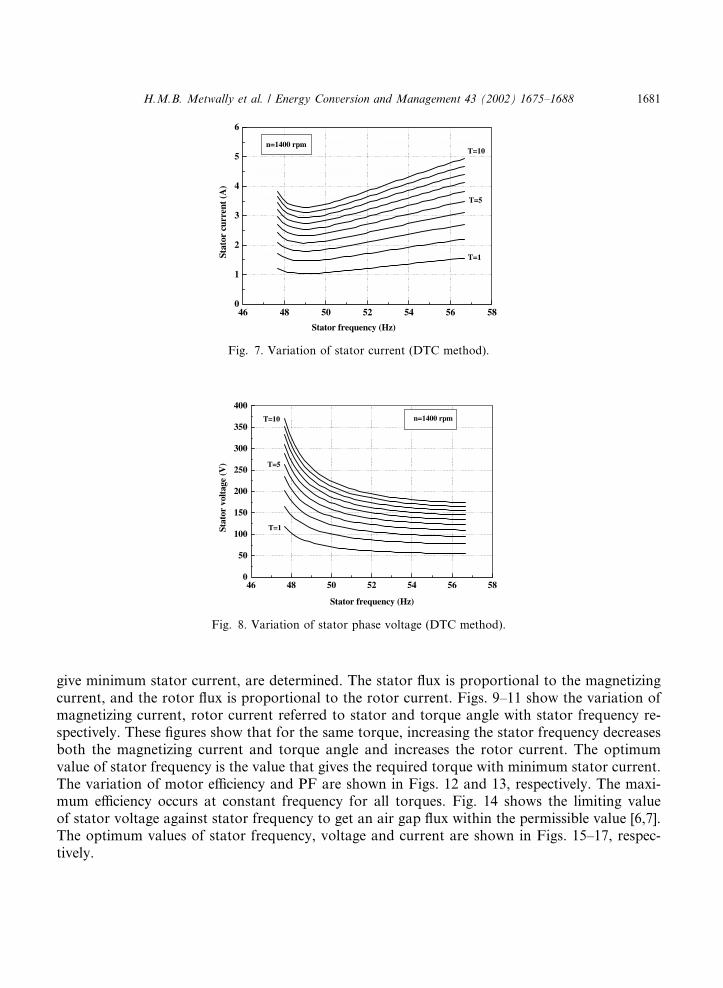
give minimum stator current, are determined. The stator flux is proportional to the magnetizingcurrent, and the rotor flux is proportional to the rotor current. Figs. 9–11 show the variation ofmagnetizing current, rotor current referred to stator and torque angle with stator frequency re-spectively. These figures show that for the same torque, increasing the stator frequency decreasesboth the magnetizing current and torque angle and increases the rotor current. The optimumvalue of stator frequency is the value that gives the required torque with minimum stator current.The variation of motor efficiency and PF are shown in Figs. 12 and 13, respectively. The maxi-mum efficiency occurs at constant frequency for all torques. Fig. 14 shows the limiting valueof stator voltage against stator frequency to get an air gap flux within the permissible value [6,7].The optimum values of stator frequency, voltage and current are shown in Figs. 15–17, respec-tively.
Fig. 7. Variation of stator current (DTC method).
Fig. 8. Variation of stator phase voltage (DTC method).
H.M.B. Metwally et al. / Energy Conversion and Management 43 (2002) 1675–1688 1681
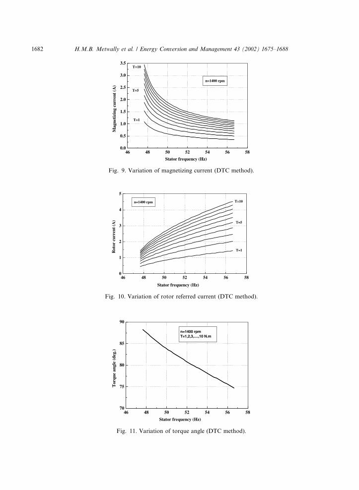
Fig. 10. Variation of rotor referred current (DTC method).
Fig. 11. Variation of torque angle (DTC method).
Fig. 9. Variation of magnetizing current (DTC method).
1682 H.M.B. Metwally et al. / Energy Conversion and Management 43 (2002) 1675–1688
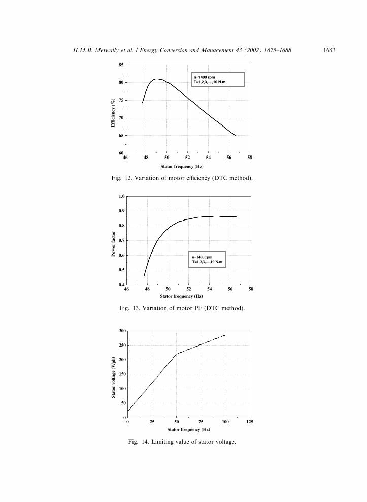
Fig. 13. Variation of motor PF (DTC method).
Fig. 14. Limiting value of stator voltage.
Fig. 12. Variation of motor efficiency (DTC method).
H.M.B. Metwally et al. / Energy Conversion and Management 43 (2002) 1675–1688 1683
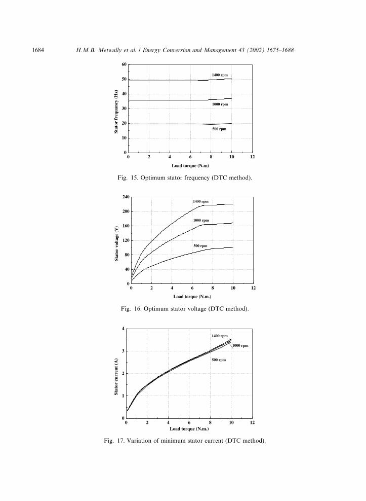
Fig. 15. Optimum stator frequency (DTC method).
Fig. 16. Optimum stator voltage (DTC method).
Fig. 17. Variation of minimum stator current (DTC method).
1684 H.M.B. Metwally et al. / Energy Conversion and Management 43 (2002) 1675–1688
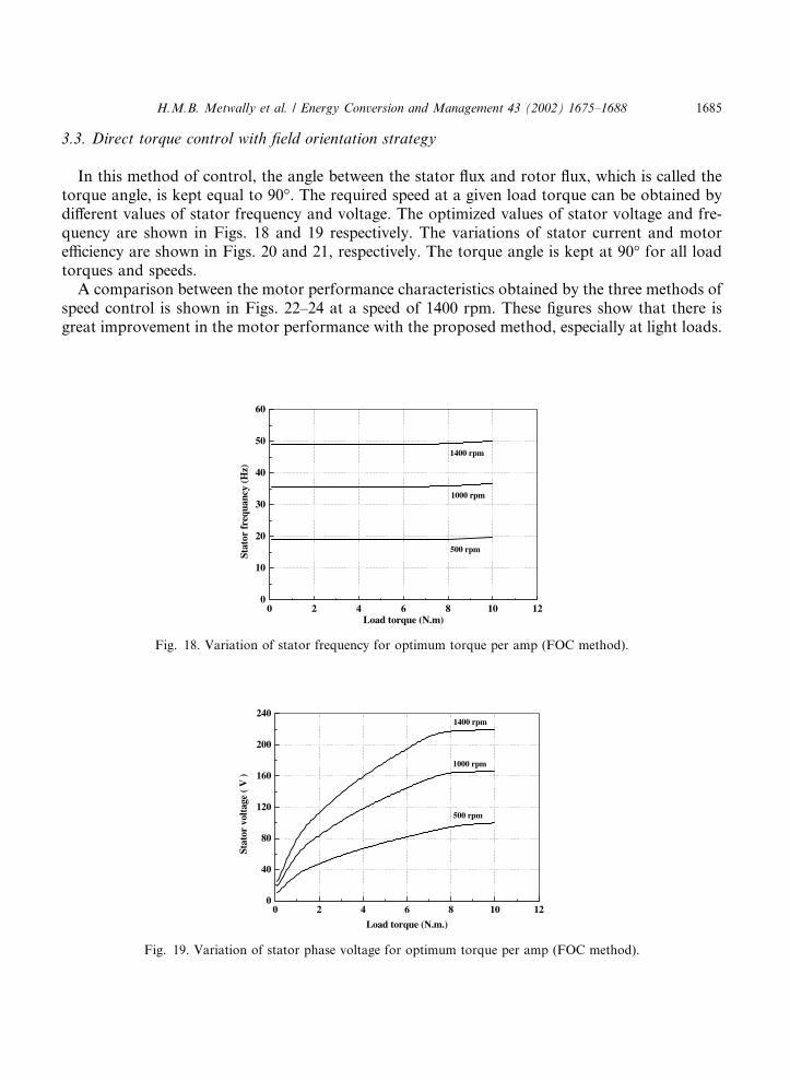
3.3. Direct torque control with field orientation strategy
In this method of control, the angle between the stator flux and rotor flux, which is called thetorque angle, is kept equal to 90�. The required speed at a given load torque can be obtained bydifferent values of stator frequency and voltage. The optimized values of stator voltage and fre-quency are shown in Figs. 18 and 19 respectively. The variations of stator current and motorefficiency are shown in Figs. 20 and 21, respectively. The torque angle is kept at 90� for all loadtorques and speeds.A comparison between the motor performance characteristics obtained by the three methods of
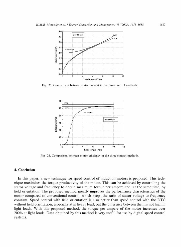
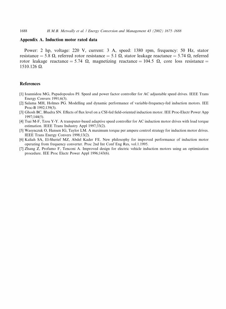
speed control is shown in Figs. 22–24 at a speed of 1400 rpm. These figures show that there isgreat improvement in the motor performance with the proposed method, especially at light loads.
Fig. 18. Variation of stator frequency for optimum torque per amp (FOC method).
Fig. 19. Variation of stator phase voltage for optimum torque per amp (FOC method).
H.M.B. Metwally et al. / Energy Conversion and Management 43 (2002) 1675–1688 1685
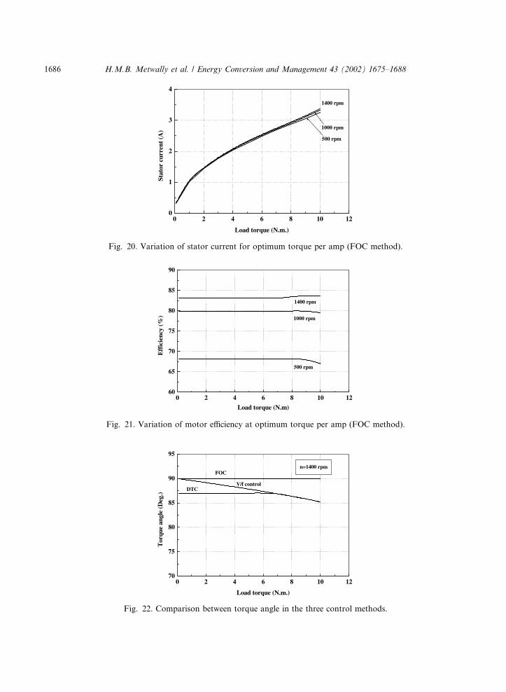
Fig. 20. Variation of stator current for optimum torque per amp (FOC method).
Fig. 21. Variation of motor efficiency at optimum torque per amp (FOC method).
Fig. 22. Comparison between torque angle in the three control methods.
1686 H.M.B. Metwally et al. / Energy Conversion and Management 43 (2002) 1675–1688
4. Conclusion
In this paper, a new technique for speed control of induction motors is proposed. This tech-nique maximizes the torque productivity of the motor. This can be achieved by controlling thestator voltage and frequency to obtain maximum torque per ampere and, at the same time, byfield orientation. The proposed method greatly improves the performance characteristics of themotor compared to conventional control, which keeps the ratio of stator voltage to frequencyconstant. Speed control with field orientation is also better than speed control with the DTCwithout field orientation, especially at in heavy load, but the difference between them is not high inlight loads. With this proposed method, the torque per ampere of the motor increases over200% at light loads. Data obtained by this method is very useful for use by digital speed controlsystems.
Fig. 23. Comparison between stator current in the three control methods.
Fig. 24. Comparison between motor efficiency in the three control methods.
H.M.B. Metwally et al. / Energy Conversion and Management 43 (2002) 1675–1688 1687
Appendix A. Induction motor rated data
Power: 2 hp, voltage: 220 V, current: 3 A, speed: 1380 rpm, frequency: 50 Hz, statorresistance ¼ 5:8 X, referred rotor resistance ¼ 5:1 X, stator leakage reactance ¼ 5:74 X, referredrotor leakage reactance ¼ 5:74 X, magnetizing reactance ¼ 104:5 X, core loss resistance ¼1510:126 X.
References
[1] Ioannidou MG, Papadopoulos PJ. Speed and power factor controller for AC adjustable speed drives. IEEE Trans
Energy Convers 1991;6(3).
[2] Salama MH, Holmes PG. Modelling and dynamic performance of variable-frequency-fed induction motors. IEE
Proc-B 1992;139(3).
[3] Ghosh BC, Bhadra SN. Effects of flux level on a CSI-fed field-oriented induction motor. IEE Proc-Electr Power App
1997;144(5).
[4] Tsai M-F, Tzou Y-Y. A transputer-based adaptive speed controller for AC induction motor drives with load torque
estimation. IEEE Trans Industry Appl 1997;33(2).
[5] Wasynczuk O, Hansen IG, Taylor LM. A maximum torque per ampere control strategy for induction motor drives.
IEEE Trans Energy Convers 1998;13(2).
[6] Kaliah SA, El-Sherief MZ, Abdel Kader FE. New philosophy for improved performance of induction motor
operating from frequency converter. Proc 2nd Int Conf Eng Res, vol.1.1995.
[7] Zhang Z, Profumo F, Tenconi A. Improved design for electric vehicle induction motors using an optimization
procedure. IEE Proc Electr Power Appl 1996;143(6).
1688 H.M.B. Metwally et al. / Energy Conversion and Management 43 (2002) 1675–1688
Related Documents