Coffey Geotechnics Pty Ltd ABN 93 056 929 483 Unit 17, Mount Penang Parklands Carinya Road Somersby NSW 2250 Australia PROPOSED SUBDIVISION AT KINGS AVE TERRIGAL Prepared For Crighton Properties Pty Ltd GEOTKARI02083AA-AC 13 February 2008 URBAN CAPABILITY ASSESSMENT WITH RESPECT TO SLOPE RISK

Welcome message from author
This document is posted to help you gain knowledge. Please leave a comment to let me know what you think about it! Share it to your friends and learn new things together.
Transcript
Coffey Geotechnics Pty Ltd ABN 93 056 929 483 Unit 17, Mount Penang Parklands Carinya Road Somersby NSW 2250 Australia
PROPOSED SUBDIVISION AT KINGS AVE TERRIGAL Prepared For
Crighton Properties Pty Ltd GEOTKARI02083AA-AC 13 February 2008
URBAN CAPABILITY ASSESSMENT WITH RESPECT TO SLOPE RISK
Coffey Geotechnics Pty Ltd ABN 93 056 929 483 GEOTKARI02083AA-AD Unit 17, Mount Penang Parklands Carinya Road Somersby NSW 2250 Australia T (+61) (2) 4340 1811 F (+61) (2) 4340 1411 www.coffey.com
13 February 2008
Crighton Properties Pty Ltd PO Box 3369 TUGGERAH NSW 2259
Attention: Peter Childs
Dear Peter
RE: PROPOSED SUBDIVISION AT KINGS AVENUE, TERRIGAL
URBAN CAPABILITY ASSESSMENT WITH RESPECT TO SLOPE RISK
Coffey Geotechnics Pty Ltd is pleased to present our urban capability assessment report for a proposed subdivision off Kings Avenue at Terrigal.
Should you have any questions regarding this report, please contact Ben Seaford on 4340 1811.
For and on behalf of Coffey Geotechnics Pty Ltd
Report prepared by: Authorised Signatory:
Ben Seaford Strider Duerinckx
Engineering Geologist Senior Engineering Geologist
Distribution List for Final Report: Original copy Coffey Geotechnics Pty Ltd
1 copy Coffey Geotechnics Pty Ltd
4 copies Crighton Properties Pty Ltd (3 hardcopies, 1 electronic)
CONTENTS
Coffey Geotechnics GEOTKARI02083AA-AD 13 February 2008
i
1 INTRODUCTION 1
2 PREVIOUS INVESTIGATIONS 1
3 PROPOSED DEVELOPMENT 1
4 SCOPE OF ASSESSMENT REQUIRED BY GCC 2
5 METHODOLOGY 2
6 SITE CONDITIONS 2
6.1 Local Geology 2
6.2 Surface Features 2
6.3 Terrain Elements 3
6.4 Slopes Greater than 20% 5
7 LABORATORY TESTING 5
8 SLOPE RISK ASSESSMENT 6
8.1 Definitions 6
8.2 Property Elements at Risk 6
8.3 Hazard Identification 6
8.4 Risk Evaluation for Existing Site Conditions 6
8.5 Geotechnical Risk Management for Subdivision Development 7
9 OTHER GEOTECHNICAL CONSIDERATIONS 9
9.1 Reactive Soils 9
9.2 Acid Sulfate Soils 9
10 CONCLUSION 10
11 LIMITATIONS 10
CONTENTS
Coffey Geotechnics GEOTKARI02083AA-AD 13 February 2008
ii
Figures
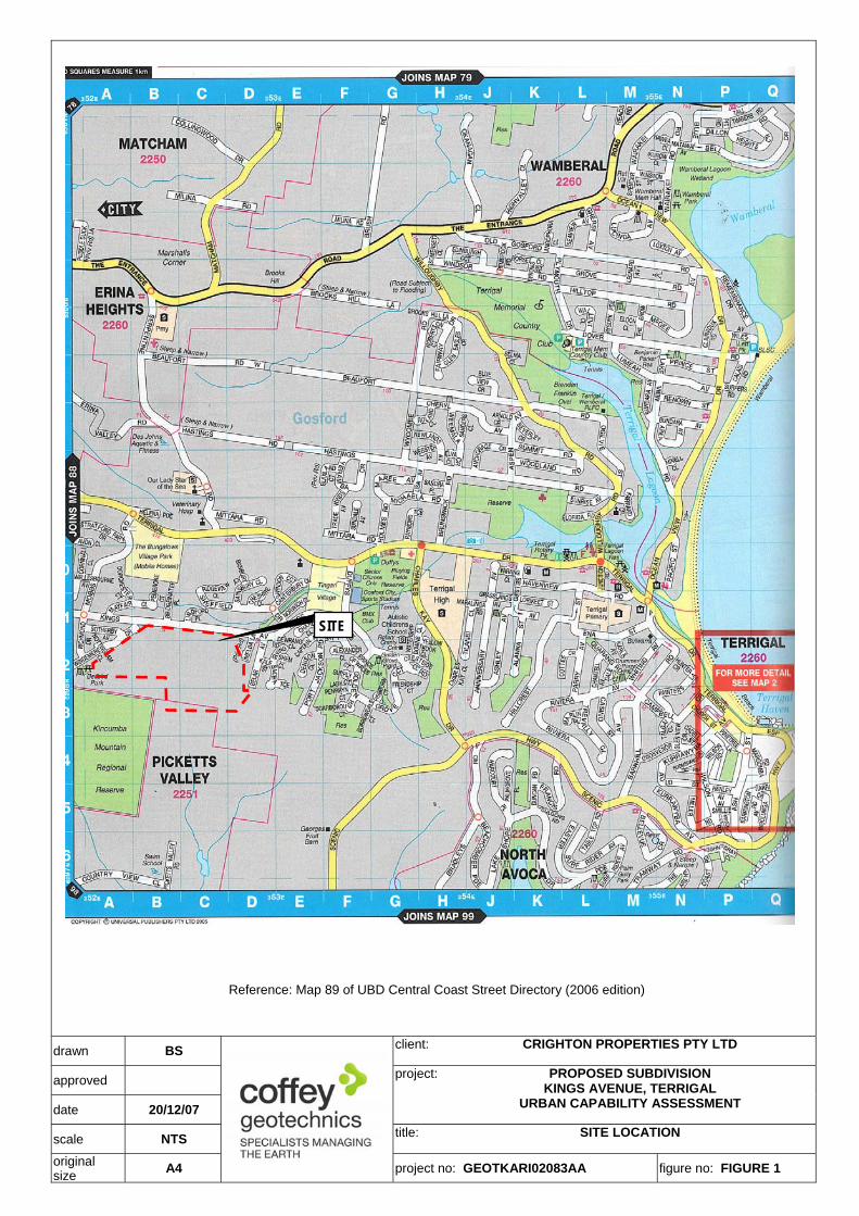
Figure 1: Site Location
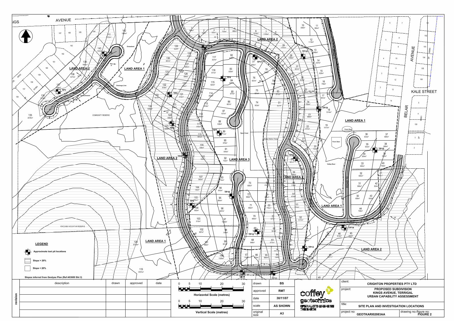
Figure 2: Site Plan and Investigation Locations
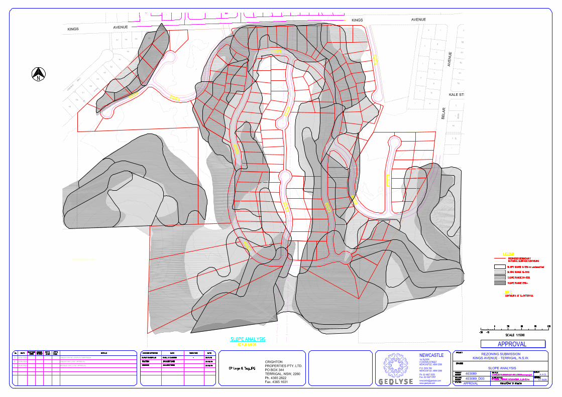
Figure 3: Site Plan by Geolyse showing slopes > 20%
Appendices
Appendix A: Engineering Borehole Logs and Explanation Sheets
Appendix B: Laboratory Results
Appendix C: Copy of reports GO540/1-AB and GO652/1-AB
Important Information about your Coffey Report
Attachments 1, 2 & 3
Landslide likelihood, consequence and risk terms for property
Proposed Subdivision at Kings Ave, Terrigal
Coffey Geotechnics GEOTKARI02083AA-AD 13 February 2008
1
1 INTRODUCTION
This report presents the results of a geotechnical assessment carried out by Coffey Geotechnics Pty Ltd (Coffey) for Crighton Properties Pty Ltd (Crighton) at the site of a proposed subdivision off Kings Avenue at Terrigal. The investigation was carried out in response to Gosford City Council (GCC) letter reference 3744897, forwarded to Coffey by Crighton.
The purpose of the work was to assess the suitability of the site for proposed residential subdivision with respect to risk of slope instability. This report provides an assessment of the risk of slope instability at the site in its existing condition and the risks associated with subdivision development. Recommendations for individual lot development are beyond the scope of this assessment.
The brief required specifications needed for the local environmental study for the rezoning application. The specifications pertaining to geotechnical issues were contained in Paragraph 3(a) and requested that the report contains assessment of:
• Description and analysis of the slopes, soils and topographical features of the site and its immediate surrounds with particular reference to GCC DCP 163 'Geotechnical Requirements for Development Applications';
• Identification of slopes, soils and topographical features which might impose constraints to future development or require specialised engineering approaches to address site constraints; and
• Location of land displaying slopes in excess of 20%.
Other geotechnical considerations, such as footing requirements, settlement, pavement design, bearing capacity, soil chemistry, soil and groundwater contamination, and the effects of mine subsidence, are beyond the scope of this assessment. These matters will be addressed at a future design stage.
2 PREVIOUS INVESTIGATIONS
In 1992 and 1993 Coffey conducted slope instability risk assessments on different parts of the site (Ref: GO540/1-AB and GO652/1-AB). A total of twenty five test pits were excavated to depths up to 3.3m. Subsurface conditions on slopes generally comprised shallow topsoil and slopewash overlying residual clays and weathered rock. Valley floors were generally underlain by relatively deep alluvium.
Slopes observed were generally between 5° to 18° with locally steeper slopes (up to 35°) in gully flanks. Minor slumping and erosion was observed on some of the gully flanks. Each respective area was assessed as having a “moderate” risk of overall slope instability based on the classification system that Coffey Geoscieces adopted at the time (based on system published in Australian Geomechanics News, Number 10, 1985).
Copies of the previous reports by Coffey have been included in Appendix C.
3 PROPOSED DEVELOPMENT The entire site is about 50ha. It is understood that the proposed subdivision involves the construction of 146 residential lots with some allotments set aside for community space and future development. Plans of the proposed development by Geolyse (Ref: 403089 Sheets D01 to D13) were provided.
Proposed Subdivision at Kings Ave, Terrigal
Coffey Geotechnics GEOTKARI02083AA-AD 13 February 2008
2
4 SCOPE OF ASSESSMENT REQUIRED BY GCC Gosford City Council (GCC) Development Control Plan No.163 (DCP163) ‘Geotechnical Requirements for Development Applications’ nominates four categories of properties and the associated minimum geotechnical assessments required to support Development Applications.
The categories are defined in Tables M1 and M2 of DCP163 and are based primarily on site geology and general slope conditions. For the geology and slope conditions assessed (outlined below), the site in its current condition is considered to be a Category 2 (medium hazard) site.
A Category 2 site requires a Class 2 geotechnical report (as defined by GCC) to support future DA for the site. Coffey has prepared a report that conforms to the Class 2 guidelines.
5 METHODOLOGY
The slope risk assessment was based on the following:
• A review of relevant geology maps and previous reports referenced in Section 2 of this report;
• Observations of surface features on the property and the surrounding area by a Principal Geotechnical Engineer on 28 November 2007;
• Twenty test pits excavated across the site to depths up to 2.5m. Test pits were generally excavated in only areas where development is proposed.
The engineering logs of the test pits are presented in Appendix A, together with explanation sheets defining the terms and symbols used. Reduced levels shown on the engineering logs were inferred from contour levels on the plan prepared by Geolyse. Test pits were located using tape measurements from site features shown on the plan by Geolyse.
The risk of slope instability has been assessed from the observed site conditions using methods consistent with those presented in the Australian Geomechanics Society publication Landslide Risk Management Concepts and Guidelines, in Australian Geomechanics News, March 2000. Based on those methods, the risks to property associated with slope instability on the subject site have been assessed using the terms presented in Coffey Attachment 1, ‘Classification of Risk of Slope Instability’, which has been adapted from the classification system formulated by the Australian Geomechanics Society and published in Australian Geomechanics News, Number 10, 1985.
6 SITE CONDITIONS
6.1 Local Geology The Gosford 1:25000 Geological Map (unpublished) indicates that the locality is underlain by rocks belonging to the Terrigal Formation of the Narrabeen Group, consisting of interbedded lithic sandstone and siltstone.
6.2 Surface Features
The site is situated on the north eastern flank of a moderately to steeply undulating ridge. This site features three roughly northeast/southwest trending spurs which forms the northeastern extent of the Kincumba Mountain Reserve. The site is located on the southern side of Kings Avenue. Existing residential development is located to the east and west, and to the north of Kings Avenue.
Proposed Subdivision at Kings Ave, Terrigal
Coffey Geotechnics GEOTKARI02083AA-AD 13 February 2008
3
The three spurs are located in the western, central and eastern portions of the site. The eastern and western spurs extend only partway across the site with the central spur intersecting the entire length of site. The crest of the central spur has been cleared for power lines. Two broad valleys occupy the areas between the spurs.
The vegetation comprises paddocks cleared of trees, light woodland areas cleared of undergrowth with grass cover and localised scrub areas. Woodland areas comprise mature native trees with the area further to the south, beyond the property boundary, being moderately vegetated by mature native species. Tree trunks are generally vertical. Some lantana and blackberry scrub occur at scattered locations around the site. Site drainage (runoff and infiltration) was judged to be good. No evidence of seepage (spring activity) was observed, except locally near the eastern boundary, however this appears to be related to runoff from adjacent development.
6.3 Terrain Elements Based on the site surface features and inferred subsurface profiles from the test pits, the site has been split up into three Land Areas. The inferred Land Areas are shown on Figure 2.
6.3.1 Land Area 1 (LA1)
LA1 comprises the valley floors and flatter footslopes located in the central eastern and central western portions of the site. The valleys are grassed paddocks. Two dams are located in the centre of the eastern valley. The valley floors are generally flat but minor slopes of about 10° were recorded where the flanks of the surrounding spurs intersect with valley floor.
Table 1 presents the inferred geotechnical model for LA1, based on test pits TP13 and TP15 and test pits from the previous investigations referenced in Section 2.
TABLE 1 – INFERRED GEOTECHNICAL UNITS FOR LA1
Unit Typical Properties
Alluvium/Colluvium Silty SAND and Clayey SAND, fine to medium grained, low plasticity. Ranging from 1.5m thick to greater than 3.5m thick.
Residual Soil Sandy CLAY, low to medium plasticity, stiff to very stiff consistency. Fine to medium grained sand.
In summary, test pits excavated in LA1 generally encountered deep soils comprising silty sand colluvial soil overlying low to medium plasticity sandy clays. It is likely that the soil depth in LA1 in the western portion of the site will encounter similar soil depths.
Groundwater inflows were not encountered in test pits excavated in LA1, in this episode of fieldwork but minor flows were encountered in the western valley in 1992.
Proposed Subdivision at Kings Ave, Terrigal
Coffey Geotechnics GEOTKARI02083AA-AD 13 February 2008
4
6.3.2 Land Area 2 (LA2)
LA2 encompasses the flanks of each spur and the steeper terrain to the south. Field slope measurements ranged from about 12° to 28°. Steeper slopes were observed further to the south of the proposed development.
Table 2 presents the inferred geotechnical model for LA2, based on test pits TP1 to TP3, TP5, TP6, TP8 to TP11, TP14 and TP16 to TP20.
TABLE 2 – INFERRED GEOTECHNICAL UNITS FOR LA2
Unit Typical Properties
Colluvium Silty SAND/SAND/Silty clayey SAND, fine to medium grained, low plastic clay fines. Thickness range between 0.2m to 1m.
Residual Soil and Extremely Weathered Rock
Sandy CLAY/CLAY/Silty CLAY, medium to high plasticity, grey-orange-red, generally very stiff to hard consistency, some fine to medium gravel. Grades into extremely weathered sandstone. Thicknesses range between 0.2m and 1.3m.
Distinctly Weathered Rock
SANDSTONE, inferred below the depth of excavator refusal. Estimated to be very low to medium strength, highly to moderately weathered. Excavator refusal was generally between 0.7 to 2m below the existing surface level.
6.3.3 Land Area 3 (LA3)
LA3 comprises the crest of the central spur extending through the centre of the site. The crest is relatively flat with slopes extending gently in all directions at a maximum of about 8°. A stand of dense native trees was observed on the central eastern portion of the spur.
Table 3 presents the inferred geotechnical model for LA3, based on test pits TP4, TP7, TP12, TP16 and TP17.
Some scattered sandstone outcrops were observed at the crest of the ridge, and rock was generally encountered at shallower depths in LA3 compared to LA1 and LA2.
Proposed Subdivision at Kings Ave, Terrigal
Coffey Geotechnics GEOTKARI02083AA-AD 13 February 2008
5
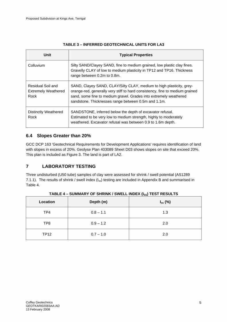
TABLE 3 – INFERRED GEOTECHNICAL UNITS FOR LA3
Unit Typical Properties
Colluvium Silty SAND/Clayey SAND, fine to medium grained, low plastic clay fines. Gravelly CLAY of low to medium plasticity in TP12 and TP16. Thickness range between 0.2m to 0.8m.
Residual Soil and Extremely Weathered Rock
SAND, Clayey SAND, CLAY/Silty CLAY, medium to high plasticity, grey-orange-red, generally very stiff to hard consistency, fine to medium grained sand, some fine to medium gravel. Grades into extremely weathered sandstone. Thicknesses range between 0.5m and 1.1m.
Distinctly Weathered Rock
SANDSTONE, inferred below the depth of excavator refusal. Estimated to be very low to medium strength, highly to moderately weathered. Excavator refusal was between 0.9 to 1.6m depth.
6.4 Slopes Greater than 20%
GCC DCP 163 'Geotechnical Requirements for Development Applications' requires identification of land with slopes in excess of 20%. Geolyse Plan 403089 Sheet D03 shows slopes on site that exceed 20%. This plan is included as Figure 3. The land is part of LA2.
7 LABORATORY TESTING
Three undisturbed (U50 tube) samples of clay were assessed for shrink / swell potential (AS1289 7.1.1). The results of shrink / swell index (Iss) testing are included in Appendix B and summarised in Table 4.
TABLE 4 – SUMMARY OF SHRINK / SWELL INDEX (ISS) TEST RESULTS
Location Depth (m) Iss (%)
TP4 0.8 – 1.1 1.3
TP8 0.9 – 1.2 2.0
TP12 0.7 – 1.0 2.0
Proposed Subdivision at Kings Ave, Terrigal
Coffey Geotechnics GEOTKARI02083AA-AD 13 February 2008
6
8 SLOPE RISK ASSESSMENT
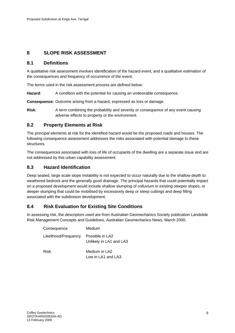
8.1 Definitions A qualitative risk assessment involves identification of the hazard event, and a qualitative estimation of the consequences and frequency of occurrence of the event.
The terms used in the risk assessment process are defined below:
Hazard: A condition with the potential for causing an undesirable consequence.
Consequence: Outcome arising from a hazard, expressed as loss or damage.
Risk: A term combining the probability and severity or consequence of any event causing adverse effects to property or the environment.
8.2 Property Elements at Risk The principal elements at risk for the identified hazard would be the proposed roads and houses. The following consequence assessment addresses the risks associated with potential damage to these structures.
The consequences associated with loss of life of occupants of the dwelling are a separate issue and are not addressed by this urban capability assessment.
8.3 Hazard Identification Deep seated, large scale slope instability is not expected to occur naturally due to the shallow depth to weathered bedrock and the generally good drainage. The principal hazards that could potentially impact on a proposed development would include shallow slumping of colluvium in existing steeper slopes, or deeper slumping that could be mobilised by excessively deep or steep cuttings and deep filling associated with the subdivision development.
8.4 Risk Evaluation for Existing Site Conditions In assessing risk, the descriptors used are from Australian Geomechanics Society publication Landslide Risk Management Concepts and Guidelines, Australian Geomechanics News, March 2000.
Consequence Medium
Likelihood/Frequency
Possible in LA2 Unlikely in LA1 and LA3
Risk Medium in LA2 Low in LA1 and LA3
Proposed Subdivision at Kings Ave, Terrigal
Coffey Geotechnics GEOTKARI02083AA-AD 13 February 2008
7
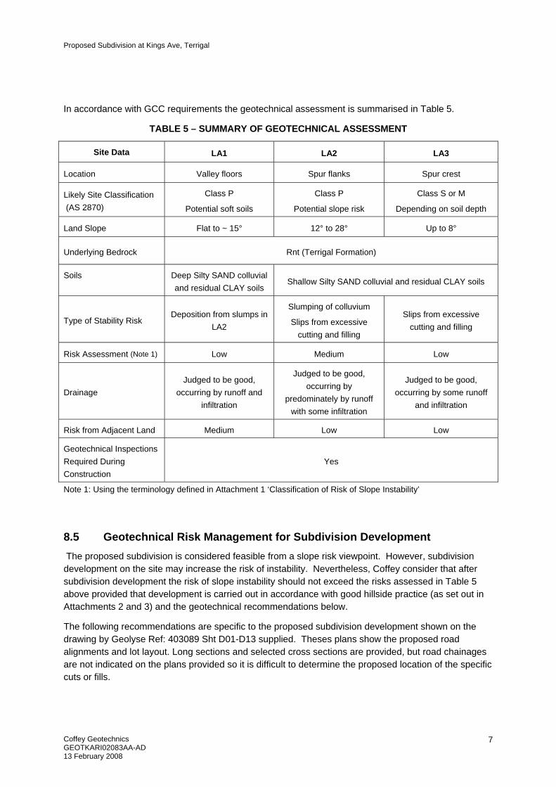
In accordance with GCC requirements the geotechnical assessment is summarised in Table 5.
TABLE 5 – SUMMARY OF GEOTECHNICAL ASSESSMENT
Site Data LA1 LA2 LA3
Location Valley floors Spur flanks Spur crest
Likely Site Classification (AS 2870)
Class P
Potential soft soils
Class P
Potential slope risk
Class S or M
Depending on soil depth
Land Slope Flat to ~ 15° 12° to 28° Up to 8°
Underlying Bedrock Rnt (Terrigal Formation)
Soils Deep Silty SAND colluvial and residual CLAY soils
Shallow Silty SAND colluvial and residual CLAY soils
Type of Stability Risk Deposition from slumps in
LA2
Slumping of colluvium
Slips from excessive cutting and filling
Slips from excessive cutting and filling
Risk Assessment (Note 1) Low Medium Low
Drainage Judged to be good,
occurring by runoff and infiltration
Judged to be good, occurring by
predominately by runoff with some infiltration
Judged to be good, occurring by some runoff
and infiltration
Risk from Adjacent Land Medium Low Low
Geotechnical Inspections Required During Construction
Yes
Note 1: Using the terminology defined in Attachment 1 ‘Classification of Risk of Slope Instability’
8.5 Geotechnical Risk Management for Subdivision Development The proposed subdivision is considered feasible from a slope risk viewpoint. However, subdivision development on the site may increase the risk of instability. Nevertheless, Coffey consider that after subdivision development the risk of slope instability should not exceed the risks assessed in Table 5 above provided that development is carried out in accordance with good hillside practice (as set out in Attachments 2 and 3) and the geotechnical recommendations below.
The following recommendations are specific to the proposed subdivision development shown on the drawing by Geolyse Ref: 403089 Sht D01-D13 supplied. Theses plans show the proposed road alignments and lot layout. Long sections and selected cross sections are provided, but road chainages are not indicated on the plans provided so it is difficult to determine the proposed location of the specific cuts or fills.
Proposed Subdivision at Kings Ave, Terrigal
Coffey Geotechnics GEOTKARI02083AA-AD 13 February 2008
8
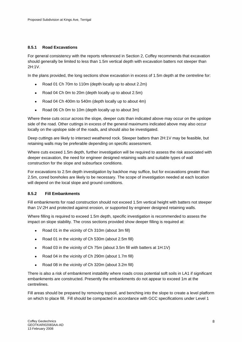
8.5.1 Road Excavations
For general consistency with the reports referenced in Section 2, Coffey recommends that excavation should generally be limited to less than 1.5m vertical depth with excavation batters not steeper than 2H:1V.
In the plans provided, the long sections show excavation in excess of 1.5m depth at the centreline for:
• Road 01 Ch 70m to 110m (depth locally up to about 2.2m)
• Road 04 Ch 0m to 20m (depth locally up to about 2.5m)
• Road 04 Ch 400m to 540m (depth locally up to about 4m)
• Road 06 Ch 0m to 10m (depth locally up to about 3m)
Where these cuts occur across the slope, deeper cuts than indicated above may occur on the upslope side of the road. Other cuttings in excess of the general maximums indicated above may also occur locally on the upslope side of the roads, and should also be investigated.
Deep cuttings are likely to intersect weathered rock. Steeper batters than 2H:1V may be feasible, but retaining walls may be preferable depending on specific assessment.
Where cuts exceed 1.5m depth, further investigation will be required to assess the risk associated with deeper excavation, the need for engineer designed retaining walls and suitable types of wall construction for the slope and subsurface conditions.
For excavations to 2.5m depth investigation by backhoe may suffice, but for excavations greater than 2.5m, cored boreholes are likely to be necessary. The scope of investigation needed at each location will depend on the local slope and ground conditions.
8.5.2 Fill Embankments
Fill embankments for road construction should not exceed 1.5m vertical height with batters not steeper than 1V:2H and protected against erosion, or supported by engineer designed retaining walls.
Where filling is required to exceed 1.5m depth, specific investigation is recommended to assess the impact on slope stability. The cross sections provided show deeper filling is required at:
• Road 01 in the vicinity of Ch 310m (about 3m fill)
• Road 01 in the vicinity of Ch 530m (about 2.5m fill)
• Road 03 in the vicinity of Ch 75m (about 3.5m fill with batters at 1H:1V)
• Road 04 in the vicinity of Ch 290m (about 1.7m fill)
• Road 08 in the vicinity of Ch 320m (about 3.2m fill)
There is also a risk of embankment instability where roads cross potential soft soils in LA1 if significant embankments are constructed. Presently the embankments do not appear to exceed 1m at the centrelines.
Fill areas should be prepared by removing topsoil, and benching into the slope to create a level platform on which to place fill. Fill should be compacted in accordance with GCC specifications under Level 1
Proposed Subdivision at Kings Ave, Terrigal
Coffey Geotechnics GEOTKARI02083AA-AD 13 February 2008
9
monitoring as described in AS 3798. Fill batters should be constructed by overfilling and then cutting back to the required slope.
8.5.3 Building platforms
Cutting and filling for building platforms for houses should be limited to a maximum depth of 1m unless site specific investigation and geotechnical assessment is conducted. The cut and fill batters should be battered at 1V:2H or flatter and protected against erosion, or supported by properly designed and constructed retaining walls as described below.
8.5.4 Retaining Walls
Retaining walls in excess of 1m height should be designed by a structural engineer familiar with the site conditions and should be designed for surcharge loading from slopes and structures and other existing or future improvements in the vicinity of the wall.
Excavations for the construction of retaining walls up to 1.5m high may adopt a temporary excavation batter of 1V:1H provided that appropriate construction planning, control of drainage and staged excavation minimises the extent of unsupported excavation. Excavations in excess of 1.5m high will require specific assessment as outlined in Section 8.5.1.
Adequate subsurface and surface drainage should be provided behind all retaining walls unless they are designed to resist hydrostatic pressures. Any subsoil drainage used on site behind retaining walls should at a minimum consist of filter sock-wrapped slotted pipe surrounded in free-draining, coarse granular backfill and should be provided around the perimeter of all excavations. Subsoil drains should be fitted with flushing and clean out points. Gradient along all drains should be sufficient to promote self-cleaning.
8.5.5 Drainage and Sewage Disposal:
Guidelines for surface and subsurface drainage are provided in the attachments to this report.
There should be no disposal of stormwater or liquid wastes on site, without further specific geotechnical assessment.
9 OTHER GEOTECHNICAL CONSIDERATIONS
9.1 Reactive Soils
The results of the shrink/swell testing indicate that the clay material encountered onsite is generally of low to moderately reactivity. It is considered that clay from cuts on site can be used as general fill. It is recommended that any material won from cuts on the site be inspected by a geotechnical authority prior to placement.
9.2 Acid Sulfate Soils
Acid Sulfate Soils (ASS) are soils containing significant concentrations of pyrite, which when it oxidises, generates sulfuric acid. Unoxidised pyritic soils are referred to as potential ASS (PASS). When the soils are exposed, the oxidation of pyrite occurs and sulfuric acids are generated, and the soils are said to be actual ASS (AASS).
Proposed Subdivision at Kings Ave, Terrigal
Coffey Geotechnics GEOTKARI02083AA-AD 13 February 2008
10
Pyritic soils typically form in waterlogged, saline sediments deposited during the Holocene period (10,000 years ago to present day). Typical these soils occur in environments below about RL 5m AHD such as tidal flats, salt marshes, mangrove swamps and bottom sediments in coastal rivers and creeks.
Disturbance of acid sulfate soils can generate significant amounts of sulfuric acid, which can lower soil and water pH and produce acid salts, which affects vegetation and aquatic life and can produce aggressive soils that may be detrimental to concrete and steel in buildings and services.
The Gosford 1:25000 Scale Acid Sulfate Soil Risk Map (Reference 1) indicates that the site is not in an area known to have occurrence of Acid Sulfate Soils.
Based on the site geology, site elevation (above RL11m) and ASS risk map review, actual or potential ASS are not likely to be encountered within the areas of the site proposed for development. Based on this observation and the proposed development details, it is considered that no ASS Management Plan is required.
10 CONCLUSION
The scope of work for this assessment was to identify soil and landscape limitations for urban development to address slope issues raised by GCC. No significant areas of instability were noted over the area. Based on the results of this assessment, it is considered that the land is generally suitable for the type of urban use proposed subject to the geotechnical constraints on development detailed in section 8.5.
11 LIMITATIONS The onus is on the owner, potential owner or interested parties to decide whether the assessed level of risk of slope instability is acceptable taking into account likely economic consequences of the risk and the recommended geotechnical constraints.
The findings contained in this report result from methodologies used in accordance with normal practices and standards. To our knowledge, they represent a reasonable interpretation of the general condition of the site. Under no circumstances, however, can it be considered that these findings represent the actual state of the site at all points. If site conditions encountered during construction vary significantly from those discussed in this report, Coffey should be advised.
Contractors using this report as a basis for preparation of tender documents should avail themselves of all relevant background information regarding the site before deciding on selection of construction materials and equipment.
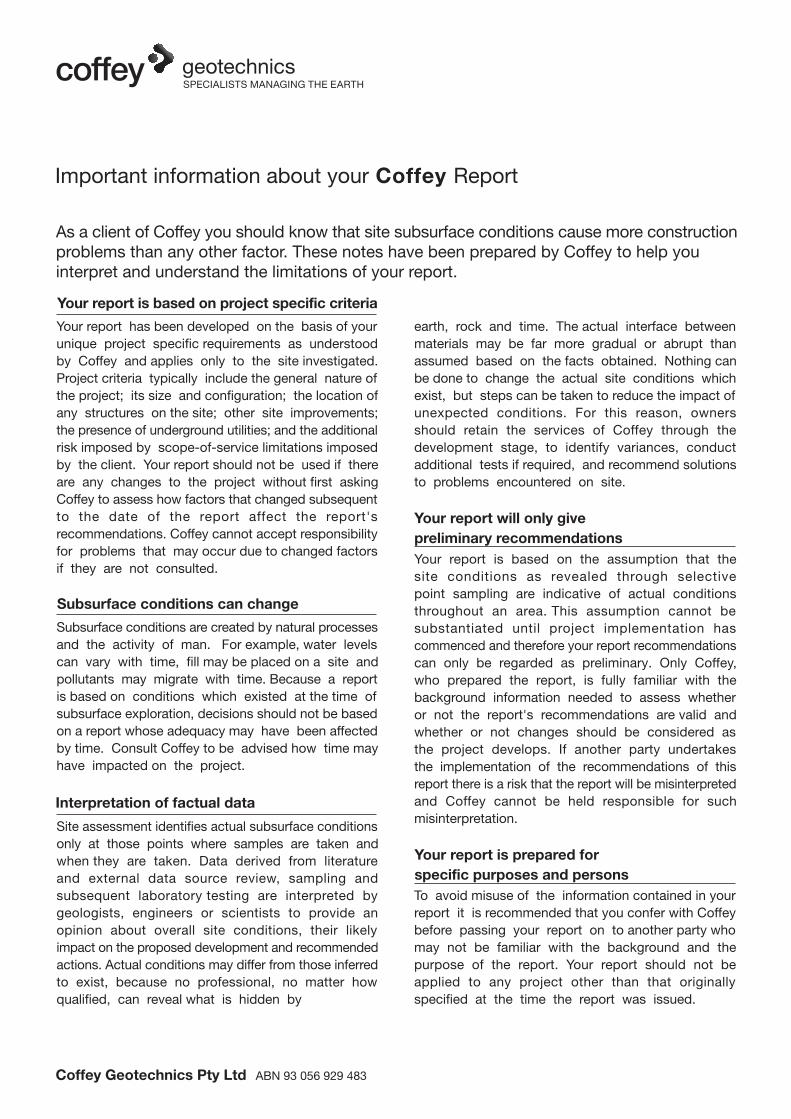
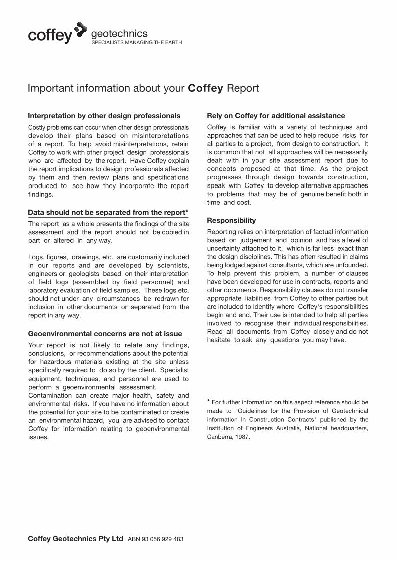
Guidance on the uses and limitations of this assessment is presented in the attached document ‘Important information about your Coffey Report’, in accordance with which this report should be read.
REFERENCES
1 Department of Land and Water Conservation (1997), Gosford 1:25000 Acid Sulfate Soil Risk Map, Edition 2
2 Ahern C R, Stone Y and Blunden B (1998) Acid Sulfate Soil Manual, Acid Sulfate Soils Management Advisory Committee, Wollongbar, NSW, August.
Coffey Geotechnics Pty Ltd ABN 93 056 929 483
As a client of Coffey you should know that site subsurface conditions cause more constructionproblems than any other factor. These notes have been prepared by Coffey to help youinterpret and understand the limitations of your report.
Your report is based on project specific criteria
Your report has been developed on the basis of yourunique project specific requirements as understoodby Coffey and applies only to the site investigated.Project criteria typically include the general nature ofthe project; its size and configuration; the location ofany structures on the site; other site improvements;the presence of underground utilities; and the additionalrisk imposed by scope-of-service limitations imposedby the client. Your report should not be used if thereare any changes to the project without first askingCoffey to assess how factors that changed subsequentto the date of the report affect the report'srecommendations. Coffey cannot accept responsibilityfor problems that may occur due to changed factorsif they are not consulted.
Subsurface conditions can change
Subsurface conditions are created by natural processesand the activity of man. For example, water levelscan vary with time, fill may be placed on a site andpollutants may migrate with time. Because a reportis based on conditions which existed at the time ofsubsurface exploration, decisions should not be basedon a report whose adequacy may have been affectedby time. Consult Coffey to be advised how time mayhave impacted on the project.
Interpretation of factual data
Site assessment identifies actual subsurface conditionsonly at those points where samples are taken andwhen they are taken. Data derived from literatureand external data source review, sampling and subsequent laboratory testing are interpreted bygeologists, engineers or scientists to provide anopinion about overall site conditions, their likelyimpact on the proposed development and recommendedactions. Actual conditions may differ from those inferredto exist, because no professional, no matter howqualified, can reveal what is hidden by
Your report will only givepreliminary recommendationsYour report is based on the assumption that thesite conditions as revealed through selectivepoint sampling are indicative of actual conditionsthroughout an area. This assumption cannot besubstantiated until project implementation hascommenced and therefore your report recommendationscan only be regarded as preliminary. Only Coffey,who prepared the report, is fully familiar with thebackground information needed to assess whetheror not the report's recommendations are valid andwhether or not changes should be considered asthe project develops. If another party undertakesthe implementation of the recommendations of thisreport there is a risk that the report will be misinterpretedand Coffey cannot be held responsible for suchmisinterpretation.
earth, rock and time. The actual interface betweenmaterials may be far more gradual or abrupt thanassumed based on the facts obtained. Nothing canbe done to change the actual site conditions whichexist, but steps can be taken to reduce the impact ofunexpected conditions. For this reason, ownersshould retain the services of Coffey through thedevelopment stage, to identify variances, conductadditional tests if required, and recommend solutionsto problems encountered on site.
Your report is prepared forspecific purposes and personsTo avoid misuse of the information contained in yourreport it is recommended that you confer with Coffeybefore passing your report on to another party whomay not be familiar with the background and thepurpose of the report. Your report should not beapplied to any project other than that originallyspecified at the time the report was issued.
Important information about your Coffey Report
* For further information on this aspect reference should bemade to "Guidelines for the Provision of Geotechnicalinformation in Construction Contracts" published by theInstitution of Engineers Australia, National headquarters,Canberra, 1987.
Interpretation by other design professionals
Costly problems can occur when other design professionals develop their plans based on misinterpretationsof a report. To help avoid misinterpretations, retainCoffey to work with other project design professionalswho are affected by the report. Have Coffey explainthe report implications to design professionals affectedby them and then review plans and specificationsproduced to see how they incorporate the reportfindings.
Data should not be separated from the report*
The report as a whole presents the findings of the siteassessment and the report should not be copied inpart or altered in any way.
Logs, figures, drawings, etc. are customarily includedin our reports and are developed by scientists,engineers or geologists based on their interpretationof field logs (assembled by field personnel) andlaboratory evaluation of field samples. These logs etc.should not under any circumstances be redrawn forinclusion in other documents or separated from thereport in any way.
Geoenvironmental concerns are not at issue
Your report is not likely to relate any findings,conclusions, or recommendations about the potentialfor hazardous materials existing at the site unlessspecifically required to do so by the client. Specialistequipment, techniques, and personnel are used toperform a geoenvironmental assessment.Contamination can create major health, safety andenvironmental risks. If you have no information aboutthe potential for your site to be contaminated or createan environmental hazard, you are advised to contactCoffey for information relating to geoenvironmentalissues.
Rely on Coffey for additional assistance
Coffey is familiar with a variety of techniques andapproaches that can be used to help reduce risks forall parties to a project, from design to construction. Itis common that not all approaches will be necessarilydealt with in your site assessment report due toconcepts proposed at that time. As the projectprogresses through design towards construction,speak with Coffey to develop alternative approachesto problems that may be of genuine benefit both intime and cost.
Responsibility
Reporting relies on interpretation of factual informationbased on judgement and opinion and has a level ofuncertainty attached to it, which is far less exact thanthe design disciplines. This has often resulted in claimsbeing lodged against consultants, which are unfounded.To help prevent this problem, a number of clauseshave been developed for use in contracts, reports andother documents. Responsibility clauses do not transferappropriate liabilities from Coffey to other parties butare included to identify where Coffey's responsibilitiesbegin and end. Their use is intended to help all partiesinvolved to recognise their individual responsibilities.Read all documents from Coffey closely and do nothesitate to ask any questions you may have.
Coffey Geotechnics Pty Ltd ABN 93 056 929 483
Important information about your Coffey Report

Figures
drawn BS client: CRIGHTON PROPERTIES PTY LTD
approved
date 20/12/07
project: PROPOSED SUBDIVISION KINGS AVENUE, TERRIGAL
URBAN CAPABILITY ASSESSMENT
scale NTS title: SITE LOCATION
original size A4
project no: GEOTKARI02083AA figure no: FIGURE 1
Reference: Map 89 of UBD Central Coast Street Directory (2006 edition)
SITE
Appendix A Engineering Logs and Explanation Sheets

DEFINITION:In engineering terms soil includes every type of uncementedor partially cemented inorganic or organic material found inthe ground. In practice, if the material can be remoulded ordisintegrated by hand in its field condition or in water it isdescribed as a soil. Other materials are described using rockdescription terms.
CLASSIFICATION SYMBOL & SOIL NAMESoils are described in accordance with the Unified SoilClassification (UCS) as shown in the table on Sheet 2.
PARTICLE SIZE DESCRIPTIVE TERMS
MOISTURE CONDITION
CONSISTENCY OF COHESIVE SOILS
DENSITY OF GRANULAR SOILS
MINOR COMPONENTS
SOIL STRUCTURE
GEOLOGICAL ORIGIN
Boulders
Cobbles
>200 mm
63 mm to 200 mm
Gravel coarse
medium
fine
20 mm to 63 mm
6 mm to 20 mm
2.36 mm to 6 mm
Sand coarse
medium
fine
600 µm to 2.36 mm
200 µm to 600 µm
75 µm to 200 µm
Looks and feels dry. Cohesive and cemented soilsare hard, friable or powdery. Uncemented granularsoils run freely through hands.
Soil feels cool and darkened in colour. Cohesivesoils can be moulded. Granular soils tend to cohere.
As for moist but with free water forming on handswhen handled.
Very Soft
Soft
Firm
Stiff
Very Stiff
Hard
Friable
<12
12 - 25
25 - 50
50 - 100
100 - 200
>200
–
A finger can be pushed well into thesoil with little effort.
A finger can be pushed into the soilto about 25mm depth.
The soil can be indented about 5mmwith the thumb, but not penetrated.
The surface of the soil can beindented with the thumb, but notpenetrated.
The surface of the soil can be marked,but not indented with thumb pressure.
The surface of the soil can be markedonly with the thumbnail.
Crumbles or powders when scrapedby thumbnail.
Very loose
Loose
Medium Dense
Dense
Very Dense
Less than 15
15 - 35
35 - 65
65 - 85
Greater than 85
Trace of
With some
Presence just detectableby feel or eye, but soilproperties little or nodifferent to generalproperties of primarycomponent.
Coarse grained soils:<5%
Fine grained soils:<15%
Presence easily detectedby feel or eye, soilproperties little differentto general properties ofprimary component.
Coarse grained soils:5 - 12%Fine grained soils:15 - 30%
Layers
Lenses
Pockets
Continuous acrossexposure or sample.
Discontinuouslayers of lenticularshape.
Irregular inclusionsof different material.
Weaklycemented
Moderatelycemented
Easily broken up byhand in air or water.
Effort is required tobreak up the soil byhand in air or water.
Extremelyweatheredmaterial
Residual soil
Aeolian soil
Alluvial soil
Colluvial soil
Fill
Lacustrine soil
Marine soil
Structure and fabric of parent rock visible.
Structure and fabric of parent rock not visible.
Deposited by wind.
Deposited by streams and rivers.
Deposited on slopes (transported downslopeby gravity).
Man made deposit. Fill may be significantlymore variable between tested locations thannaturally occurring soils.
Deposited by lakes.
Deposited in ocean basins, bays, beachesand estuaries.
Dry
Moist
Wet
TERM ASSESSMENTGUIDE
PROPORTION OFMINOR COMPONENT IN:
TERM DENSITY INDEX (%)
ZONING CEMENTING
WEATHERED IN PLACE SOILS
TRANSPORTED SOILS
TERMUNDRAINEDSTRENGTHsu (kPa)
FIELD GUIDE
Soil Description Explanation Sheet (1 of 2)
NAME SUBDIVISION SIZE
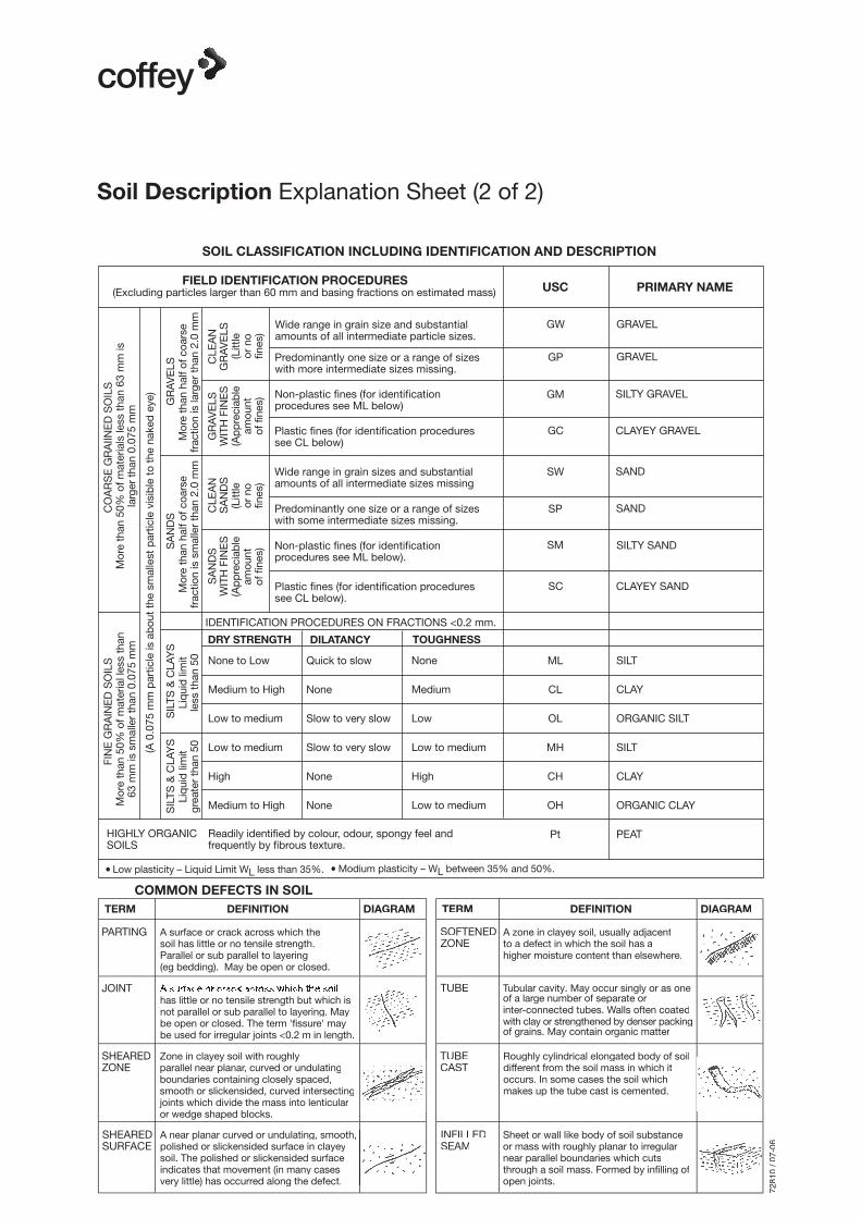
SOIL CLASSIFICATION INCLUDING IDENTIFICATION AND DESCRIPTION
COMMON DEFECTS IN SOIL
(Excluding particles larger than 60 mm and basing fractions on estimated mass)
Wide range in grain size and substantialamounts of all intermediate particle sizes.
Predominantly one size or a range of sizeswith more intermediate sizes missing.
Non-plastic fines (for identificationprocedures see ML below)
Plastic fines (for identification proceduressee CL below)
Wide range in grain sizes and substantialamounts of all intermediate sizes missing
Predominantly one size or a range of sizeswith some intermediate sizes missing.
Non-plastic fines (for identificationprocedures see ML below).
Plastic fines (for identification proceduressee CL below).
IDENTIFICATION PROCEDURES ON FRACTIONS <0.2 mm.
None to Low
Medium to High
Low to medium
Low to medium
High
Medium to High
Quick to slow
None
Slow to very slow
Slow to very slow
None
None
None
Medium
Low
Low to medium
High
Low to medium
ML
CL
OL
MH
CH
OH
Pt
SILT
CLAY
ORGANIC SILT
SILT
CLAY
ORGANIC CLAY
PEAT
GW
GP
GM
GC
SW
SP
SM
SC
GRAVEL
GRAVEL
SILTY GRAVEL
CLAYEY GRAVEL
SAND
SAND
SILTY SAND
CLAYEY SAND
HIGHLY ORGANICSOILS
Readily identified by colour, odour, spongy feel andfrequently by fibrous texture.
● Low plasticity – Liquid Limit WL less than 35%. ● Modium plasticity – WL between 35% and 50%.
PARTING
JOINT
SHEAREDZONE
SHEAREDSURFACE
A surface or crack across which thesoil has little or no tensile strength.Parallel or sub parallel to layering(eg bedding). May be open or closed.
has little or no tensile strength but which isnot parallel or sub parallel to layering. Maybe open or closed. The term 'fissure' maybe used for irregular joints <0.2 m in length.
Zone in clayey soil with roughlyparallel near planar, curved or undulatingboundaries containing closely spaced,smooth or slickensided, curved intersectingjoints which divide the mass into lenticularor wedge shaped blocks.
A near planar curved or undulating, smooth,polished or slickensided surface in clayeysoil. The polished or slickensided surfaceindicates that movement (in many casesvery little) has occurred along the defect.
A zone in clayey soil, usually adjacentto a defect in which the soil has ahigher moisture content than elsewhere.
SOFTENEDZONE
TUBE
TUBECAST
INFILLEDSEAM
Tubular cavity. May occur singly or as oneof a large number of separate orinter-connected tubes. Walls often coatedwith clay or strengthened by denser packingof grains. May contain organic matter
Roughly cylindrical elongated body of soildifferent from the soil mass in which itoccurs. In some cases the soil whichmakes up the tube cast is cemented.
Sheet or wall like body of soil substanceor mass with roughly planar to irregularnear parallel boundaries which cutsthrough a soil mass. Formed by infilling ofopen joints.
FIN
E G
RA
INE
D S
OIL
SM
ore
than
50%
of m
ater
ial l
ess
than
63 m
m is
sm
alle
r th
an 0
.075
mm
(A 0
.075
mm
par
ticle
is a
bou
t th
e sm
alle
st p
artic
le v
isib
le t
o th
e na
ked
eye
)
SIL
TS &
CLA
YS
SIL
TS &
CLA
YS
SA
ND
SG
RA
VE
LSLi
qui
d li
mit
grea
ter
than
50
Liq
uid
lim
itle
ss th
an 5
0M
ore
than
hal
f of c
oars
efr
actio
n is
sm
alle
r th
an 2
.0 m
mM
ore
than
hal
f of c
oars
efr
actio
n is
larg
er th
an 2
.0 m
m
SA
ND
SW
ITH
FIN
ES
CLE
AN
SA
ND
SG
RA
VE
LSW
ITH
FIN
ES
CLE
AN
GR
AV
ELS
(Ap
pre
ciab
leam
ount
of fi
nes)
(Litt
leor
no
fines
)
(Ap
pre
ciab
leam
ount
of fi
nes)
(Litt
leor
no
fines
)
CO
AR
SE
GR
AIIN
ED
SO
ILS
Mor
e th
an 5
0% o
f mat
eria
ls le
ss th
an 6
3 m
m is
larg
er th
an 0
.075
mm
FIELD IDENTIFICATION PROCEDURES PRIMARY NAME
TERM DEFINITION DIAGRAM TERM DEFINITION DIAGRAM
DRY STRENGTH DILATANCY TOUGHNESS
Soil Description Explanation Sheet (2 of 2)
USC
7281
0 / 0
7-06
SM
water
moisture
material substance
met
hod
cons
iste
ncy/
dens
ity in
dex
0.5
1.0
1.5
2.0
2.5
TES
TPIT
GE
OTK
AR
I020
83A
A.G
PJ
CO
FFE
Y.G
DT
13.
2.08
kPa
consistency/density index
Non
e O
bser
ved
no resistanceranging torefusal
natural exposureexisting excavationbackhoe bucketbulldozer bladeripperexcavator
VSSFStVStHFbVLLMDDVD
notessamples,tests, etc
E
N nil
1 of 1su
ppor
t
Test pit location:
100
200
300
400
1 2 3 4
water levelon date shown
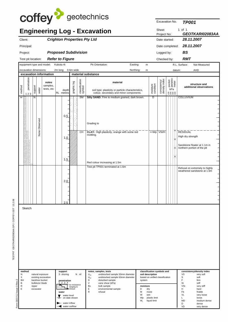
Red colour increasing at 1.5m
CH <<Wp
D
Test pit TP001 terminated at 1.6m
CLAY: High plasticity, orange with some redmottling.
Grading to
Silty SAND: Fine to medium grained, dark brown.
VSt/H
Refusal on extremely to highlyweathered sandstone at 1.6m
Sandstone floater at 1.1m innorthern portion of the pit
High dry strength
RESIDUAL
COLLUVIUMN
drymoistwetplastic limitliquid limit
RL
Sketch
Engineering Log - Excavation
very softsoftfirmstiffvery stiffhardfriablevery looseloosemedium densedensevery dense
notes, samples, tests
equipment type and model:
excavation dimensions:
excavation information
clas
sific
atio
nsy
mbo
lmaterial
wat
er
moi
stur
eco
nditi
on
depthmetres1 2 3
structure andadditional observations
water outflow
classification symbols andsoil descriptionbased on unified classificationsystem
Crighton Properties Pty Ltd
Proposed SubdivisionRefer to Figure
Project No:
28.11.200728.11.2007
BSRMT
GEOTKARI02083AA
TP001
Date started:
Date completed:
Logged by:
Checked by:
Sheet
R.L. Surface:
datum:
Not Measured
AHD
Client:
Principal:
Project:
DMWWpWL
supportS shoring
Form
GE
O 5
.2 Is
sue
3 R
ev.2
Pit Orientation: Easting:
Northing:
methodNXBHBRE
penetration
Kubota 4t
2m long 0.6m wide
water inflow
pock
etpe
netro
-m
eter
grap
hic
log
pene
tratio
n
soil type: plasticity or particle characteristics,colour, secondary and minor components.
m
m
Excavation No.
undisturbed sample 50mm diameterundisturbed sample 63mm diameterdisturbed samplevane shear (kPa)bulk sampleenvironmental samplerefusal
U50
U63
DVBsER
0.5
1.0
1.5
2.0
2.5
E
moisture
material substance
VSSFStVStHFbVLLMDDVD
met
hod
CH
consistency/density indexN nil
Non
e O
bser
ved
no resistanceranging torefusal
natural exposureexisting excavationbackhoe bucketbulldozer bladeripperexcavator
water
kPa
1 of 1su
ppor
t
Test pit location:
100
200
300
400
1 2 3 4
water levelon date shown
cons
iste
ncy/
dens
ity in
dex
notessamples,tests, etc
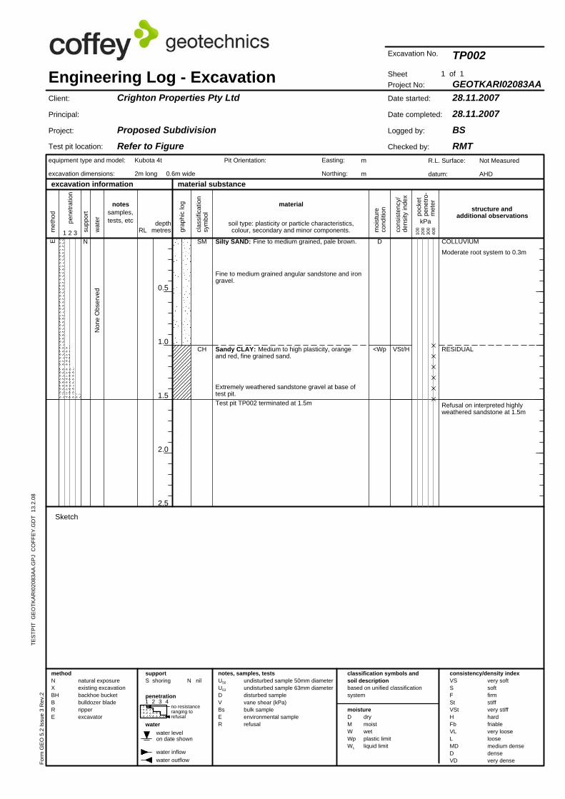
Extremely weathered sandstone gravel at base oftest pit.
SM
<Wp
D
Test pit TP002 terminated at 1.5m
Sandy CLAY: Medium to high plasticity, orangeand red, fine grained sand.
Fine to medium grained angular sandstone and irongravel.
Silty SAND: Fine to medium grained, pale brown.
VSt/H
Refusal on interpreted highlyweathered sandstone at 1.5m
RESIDUAL
Moderate root system to 0.3m
COLLUVIUMN
drymoistwetplastic limitliquid limit
RL
Engineering Log - Excavation
very softsoftfirmstiffvery stiffhardfriablevery looseloosemedium densedensevery dense
notes, samples, tests
equipment type and model:
excavation dimensions:
excavation information
clas
sific
atio
nsy
mbo
lmaterial
wat
er
moi
stur
eco
nditi
on
depthmetres1 2 3
structure andadditional observations
water outflow
classification symbols andsoil descriptionbased on unified classificationsystem
Crighton Properties Pty Ltd
Proposed SubdivisionRefer to Figure
Project No:
28.11.200728.11.2007
BSRMT
GEOTKARI02083AA
TP002
Date started:
Date completed:
Logged by:
Checked by:
Sheet
R.L. Surface:
datum:
Not Measured
AHD
Client:
Principal:
Project:
DMWWpWL
supportS shoring
Form
GE
O 5
.2 Is
sue
3 R
ev.2
Pit Orientation: Easting:
Northing:
water inflow
penetration
Kubota 4t
2m long 0.6m wide
pock
etpe
netro
-m
eter
Sketch
TES
TPIT
GE
OTK
AR
I020
83A
A.G
PJ
CO
FFE
Y.G
DT
13.
2.08
grap
hic
log
pene
tratio
n
soil type: plasticity or particle characteristics,colour, secondary and minor components.
m
m
Excavation No.
undisturbed sample 50mm diameterundisturbed sample 63mm diameterdisturbed samplevane shear (kPa)bulk sampleenvironmental samplerefusal
U50
U63
DVBsER
methodNXBHBRE
met
hod
VSSFStVStHFbVLLMDDVD
water
moisture
material substance
TES
TPIT
GE
OTK
AR
I020
83A
A.G
PJ
CO
FFE
Y.G
DT
13.
2.08
1 2 3 4
0.5
1.0
1.5
2.0
2.5
notessamples,tests, etc
drymoistwetplastic limitliquid limit
Non
e
water outflow
no resistanceranging torefusal
natural exposureexisting excavationbackhoe bucketbulldozer bladeripperexcavator
cons
iste
ncy/
dens
ity in
dex
water levelon date shown
kPa
N nil
1 of 1su
ppor
t
Test pit location:
100
200
300
400
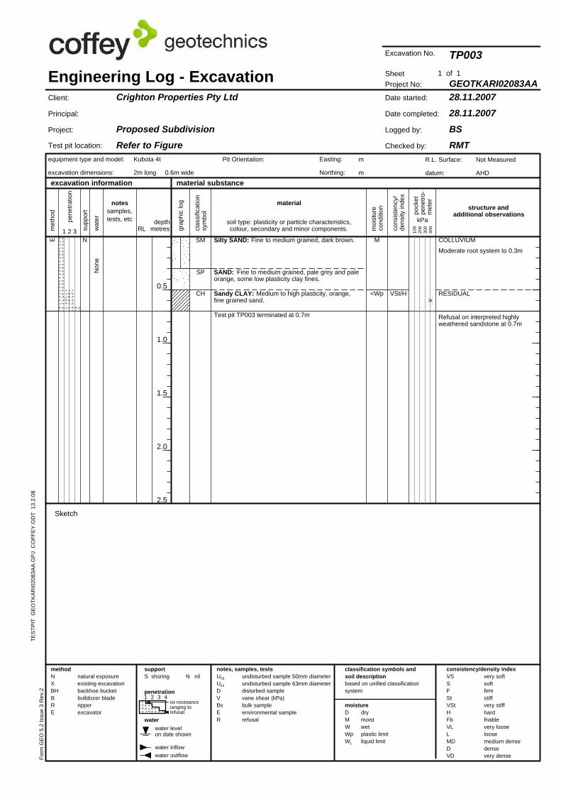
CH
Test pit TP003 terminated at 0.7m
<Wp
M
Sandy CLAY: Medium to high plasticity, orange,fine grained sand.
SAND: Fine to medium grained, pale grey and paleorange, some low plasticity clay fines.
Silty SAND: Fine to medium grained, dark brown.
VSt/H
COLLUVIUM
Sketch
SP
SME
Refusal on interpreted highlyweathered sandstone at 0.7m
Moderate root system to 0.3m
N
RESIDUAL
material
Engineering Log - Excavation
very softsoftfirmstiffvery stiffhardfriablevery looseloosemedium densedensevery dense
notes, samples, tests
equipment type and model:
excavation dimensions:
excavation information
water inflow
classification symbols andsoil descriptionbased on unified classificationsystem
RLwat
er
moi
stur
eco
nditi
on
depthmetres1 2 3
consistency/density index
clas
sific
atio
nsy
mbo
l
Crighton Properties Pty Ltd
Proposed SubdivisionRefer to Figure
Project No:
28.11.200728.11.2007
BSRMT
GEOTKARI02083AA
TP003
Date started:
Date completed:
Logged by:
Checked by:
Sheet
R.L. Surface:
datum:
Not Measured
AHD
Client:
Principal:
Project:
structure andadditional observations
penetration
methodNXBHBRE D
MWWpWL
supportS shoring
Form
GE
O 5
.2 Is
sue
3 R
ev.2
Easting:
Northing:
undisturbed sample 50mm diameterundisturbed sample 63mm diameterdisturbed samplevane shear (kPa)bulk sampleenvironmental samplerefusal
Pit Orientation:
U50
U63
DVBsER
pock
etpe
netro
-m
eter
grap
hic
log
pene
tratio
n
soil type: plasticity or particle characteristics,colour, secondary and minor components.
m
m
Excavation No.
Kubota 4t
2m long 0.6m wide
0.5
1.0
1.5
2.0
2.5
TES
TPIT
GE
OTK
AR
I020
83A
A.G
PJ
CO
FFE
Y.G
DT
13.
2.08
water
CL-CH
SC
SME
supp
ort
natural exposureexisting excavationbackhoe bucketbulldozer bladeripperexcavator
Non
e O
bser
ved
notessamples,tests, etc kPa
material substance
1 of 1
moisture
Test pit location:
100
200
300
400
1 2 3 4
water levelon date shown
cons
iste
ncy/
dens
ity in
dex
met
hod
VSSFStVStHFbVLLMDDVD
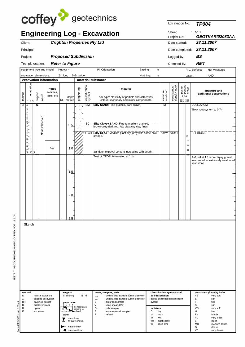
Refusal at 1.1m on clayey gravelinterpreted as extremely weatheredsandstone
N nil
Test pit TP004 terminated at 1.1m
<<Wp
M
Sandstone gravel content increasing with depth.
Silty CLAY: Medium plasticity, grey with some paleorange.
Silty Clayey SAND: Fine to medium grained,brown-grey-dark red, low plasticity clay fines.
Silty SAND: Fine grained, dark brown.
VSt/H
no resistanceranging torefusal
RESIDUAL
Thick root system to 0.7m
COLLUVIUM
U50
N
wat
er
Engineering Log - Excavation
very softsoftfirmstiffvery stiffhardfriablevery looseloosemedium densedensevery dense
notes, samples, tests
equipment type and model:
excavation dimensions:
excavation information
clas
sific
atio
nsy
mbo
l
classification symbols andsoil descriptionbased on unified classificationsystem
water outflow
RL moi
stur
eco
nditi
on
depthmetres1 2 3
structure andadditional observations
material
Crighton Properties Pty Ltd
Proposed SubdivisionRefer to Figure
Project No:
28.11.200728.11.2007
BSRMT
GEOTKARI02083AA
TP004
Date started:
Date completed:
Logged by:
Checked by:
Sheet
R.L. Surface:
datum:
Not Measured
AHD
Client:
Principal:
Project:
Sketch
supportS shoring
Form
GE
O 5
.2 Is
sue
3 R
ev.2
Pit Orientation: Easting:
Northing:
methodNXBHBRE
Kubota 4t
2m long 0.6m wide
water inflow
grap
hic
log
drymoistwetplastic limitliquid limit
pock
etpe
netro
-m
eter
DMWWpWL
pene
tratio
n
soil type: plasticity or particle characteristics,colour, secondary and minor components.
m
m
Excavation No.
undisturbed sample 50mm diameterundisturbed sample 63mm diameterdisturbed samplevane shear (kPa)bulk sampleenvironmental samplerefusal
U50
U63
DVBsER
penetration
consistency/density index
TES
TPIT
GE
OTK
AR
I020
83A
A.G
PJ
CO
FFE
Y.G
DT
13.
2.08
water levelon date shown
cons
iste
ncy/
dens
ity in
dex
met
hod
VSSFStVStHFbVLLMDDVD
water
100
200
300
400
material substance
Test pit location:
0.5
1.0
1.5
2.0
2.5
moisture
water inflow
Non
e
drymoistwetplastic limitliquid limit
consistency/density index
water outflow
no resistanceranging torefusal
1 2 3 4
notessamples,tests, etc kPa
N nil
1 of 1su
ppor
t
natural exposureexisting excavationbackhoe bucketbulldozer bladeripperexcavator
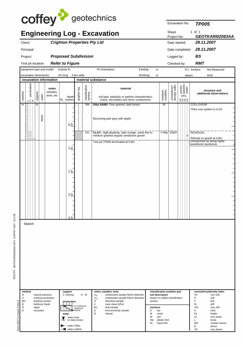
Test pit TP005 terminated at 0.8m
<<Wp
M
CLAY; High plasticity, dark orange, some fine tomedium grained angular sandstone gravel.
Becoming pale grey with depth.
Silty SAND: Fine grained, dark brown.
VSt/H
Thick root system to 0.2m
Kubota 4t
2m long 0.6m wide
CH
SME
RESIDUAL
COLLUVIUMN
Refusal on gravel at 0.8minterepreted as being highlyweathered sandstone
classification symbols andsoil descriptionbased on unified classificationsystem
Engineering Log - Excavation
very softsoftfirmstiffvery stiffhardfriablevery looseloosemedium densedensevery dense
notes, samples, tests
equipment type and model:
excavation dimensions:
clas
sific
atio
nsy
mbo
lmaterial
RLwat
er
moi
stur
eco
nditi
on
depthmetres1 2 3
Sketch
excavation information
R.L. Surface:
datum:
Project No:
28.11.200728.11.2007
BSRMT
GEOTKARI02083AA
TP005
Date started:
Date completed:
Logged by:
Checked by:
Client:
Principal:
Project:
Crighton Properties Pty Ltd
Proposed SubdivisionRefer to Figure
Not Measured
AHD
Sheet
Easting:
Northing:
structure andadditional observations
U50
U63
DVBsER
penetration
methodNXBHBRE D
MWWpWL
supportS shoring
Pit Orientation:
Excavation No.
Form
GE
O 5
.2 Is
sue
3 R
ev.2
pock
etpe
netro
-m
eter
grap
hic
log
pene
tratio
n
soil type: plasticity or particle characteristics,colour, secondary and minor components.
m
m
undisturbed sample 50mm diameterundisturbed sample 63mm diameterdisturbed samplevane shear (kPa)bulk sampleenvironmental samplerefusal
material substance
100
200
300
400
1 2 3 4
water levelon date shown
cons
iste
ncy/
dens
ity in
dex
met
hod
VSSFStVStHFbVLLMDDVD
moisture
1 of 1
water
Non
e
water inflow
Sketch
drymoistwetplastic limitliquid limit
consistency/density index
water outflow
Test pit location:
natural exposureexisting excavationbackhoe bucketbulldozer bladeripperexcavator
supp
ort
notessamples,tests, etc kPa
N nil
no resistanceranging torefusal
0.5
1.0
1.5
2.0
2.5
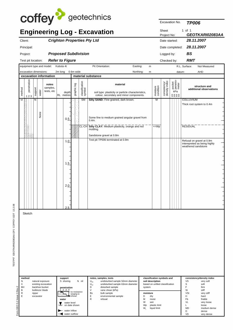
M
Test pit TP006 terminated at 0.9m
Sandstone gravel at 0.8m
Silty CLAY: Medium plasticity, orange and redmottling.
Some fine to medium grained angular gravel from0.4m.
Silty SAND: Fine grained, dark brown.
<<WpCL-CH
SM
Refusal on gravel at 0.9minterepreted as being highlyweathered sandstone
RESIDUAL
Thick root system to 0.4m
COLLUVIUMNE
classification symbols andsoil descriptionbased on unified classificationsystem
TES
TPIT
GE
OTK
AR
I020
83A
A.G
PJ
CO
FFE
Y.G
DT
13.
2.08
Engineering Log - Excavation
very softsoftfirmstiffvery stiffhardfriablevery looseloosemedium densedensevery dense
notes, samples, tests
equipment type and model:
excavation dimensions:
clas
sific
atio
nsy
mbo
lmaterial
RLwat
er
moi
stur
eco
nditi
on
depthmetres
Kubota 4t
2m long 0.6m wide
structure andadditional observations
excavation information
R.L. Surface:
datum:
Project No:
28.11.200728.11.2007
BSRMT
GEOTKARI02083AA
TP006
Date started:
Date completed:
Logged by:
Checked by:
Client:
Principal:
Project:
Crighton Properties Pty Ltd
Proposed SubdivisionRefer to Figure
Not Measured
AHD
Sheet
1 2 3
penetration
methodNXBHBRE D
MWWpWL
supportS shoring
Form
GE
O 5
.2 Is
sue
3 R
ev.2
U50
U63
DVBsER
Easting:
Northing:
undisturbed sample 50mm diameterundisturbed sample 63mm diameterdisturbed samplevane shear (kPa)bulk sampleenvironmental samplerefusal
Pit Orientation:
pock
etpe
netro
-m
eter
grap
hic
log
pene
tratio
n
soil type: plasticity or particle characteristics,colour, secondary and minor components.
m
m
Excavation No.
VSSFStVStHFbVLLMDDVD
water
moisture
material substance
TES
TPIT
GE
OTK
AR
I020
83A
A.G
PJ
CO
FFE
Y.G
DT
13.
2.08
water levelon date shown
0.5
1.0
1.5
2.0
2.5
kPa
consistency/density index
Non
e
no resistanceranging torefusal
natural exposureexisting excavationbackhoe bucketbulldozer bladeripperexcavator
met
hod
notessamples,tests, etc
cons
iste
ncy/
dens
ity in
dex
N nil
1 of 1su
ppor
t
Test pit location:
100
200
300
400
1 2 3 4
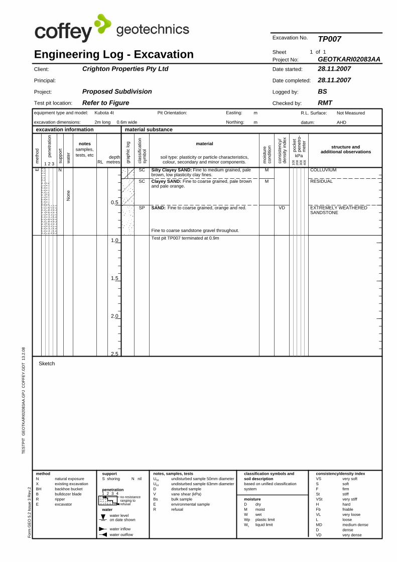
SC
Fine to coarse sandstone gravel throughout.
M
M
Test pit TP007 terminated at 0.9m
SAND: Fine to coarse grained, orange and red.
Clayey SAND: Fine to coarse grained, pale brownand pale orange.
Silty Clayey SAND: Fine to medium grained, palebrown, low plasticity clay fines.
VD
drymoistwetplastic limitliquid limit
SCE
EXTREMELY WEATHEREDSANDSTONE
COLLUVIUM
SP
N
RESIDUAL
RL
Sketch
Engineering Log - Excavation
very softsoftfirmstiffvery stiffhardfriablevery looseloosemedium densedensevery dense
notes, samples, tests
equipment type and model:
excavation dimensions:
excavation information
clas
sific
atio
nsy
mbo
lmaterial
wat
er
moi
stur
eco
nditi
on
depthmetres1 2 3
structure andadditional observations
water outflow
classification symbols andsoil descriptionbased on unified classificationsystem
Crighton Properties Pty Ltd
Proposed SubdivisionRefer to Figure
Project No:
28.11.200728.11.2007
BSRMT
GEOTKARI02083AA
TP007
Date started:
Date completed:
Logged by:
Checked by:
Sheet
R.L. Surface:
datum:
Not Measured
AHD
Client:
Principal:
Project:
methodNXBHBRE D
MWWpWL
supportS shoring
Form
GE
O 5
.2 Is
sue
3 R
ev.2
Pit Orientation: Easting:
Northing:
U50
U63
DVBsER
Kubota 4t
2m long 0.6m wide
water inflow
grap
hic
log
pock
etpe
netro
-m
eter
penetration
pene
tratio
n
soil type: plasticity or particle characteristics,colour, secondary and minor components.
m
m
Excavation No.
undisturbed sample 50mm diameterundisturbed sample 63mm diameterdisturbed samplevane shear (kPa)bulk sampleenvironmental samplerefusal
VSSFStVStHFbVLLMDDVD
water
moisture
material substance
drymoistwetplastic limitliquid limit
water levelon date shown
0.5
1.0
1.5
2.0
2.5
kPa
Non
e O
bser
ved
water outflow
no resistanceranging torefusal
natural exposureexisting excavationbackhoe bucketbulldozer bladeripperexcavator
met
hod
notessamples,tests, etc
cons
iste
ncy/
dens
ity in
dex
N nil
1 of 1su
ppor
t
Test pit location:
100
200
300
400
1 2 3 4
E
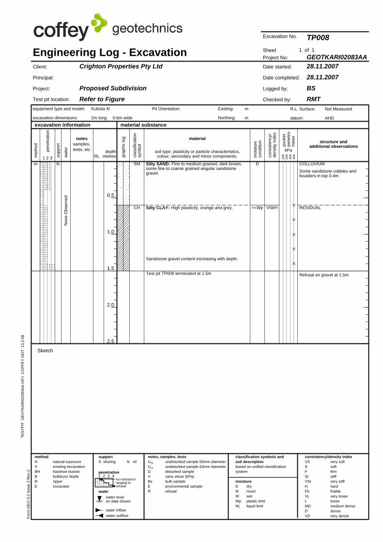
Test pit TP008 terminated at 1.5m
CH <<Wp
D
Sandstone gravel content increasing with depth.
Silty CLAY: High plasticity, orange and grey.
Silty SAND: Fine to medium grained, dark brown,some fine to coarse grained angular sandstonegravel.
VSt/H
Sketch
Refusal on gravel at 1.5m
RESIDUAL
Some sandstone cobbles andboulders in top 0.4m
COLLUVIUMN SM
RL
TES
TPIT
GE
OTK
AR
I020
83A
A.G
PJ
CO
FFE
Y.G
DT
13.
2.08
Engineering Log - Excavation
very softsoftfirmstiffvery stiffhardfriablevery looseloosemedium densedensevery dense
notes, samples, tests
equipment type and model:
excavation dimensions:
excavation information
clas
sific
atio
nsy
mbo
lmaterial
wat
er
moi
stur
eco
nditi
on
depthmetres1 2 3
structure andadditional observations
consistency/density indexclassification symbols andsoil descriptionbased on unified classificationsystem
Crighton Properties Pty Ltd
Proposed SubdivisionRefer to Figure
Project No:
28.11.200728.11.2007
BSRMT
GEOTKARI02083AA
TP008
Date started:
Date completed:
Logged by:
Checked by:
Sheet
R.L. Surface:
datum:
Not Measured
AHD
Client:
Principal:
Project:
Kubota 4t
2m long 0.6m wide
DMWWpWL
supportS shoring
Form
GE
O 5
.2 Is
sue
3 R
ev.2
Pit Orientation: Easting:
Northing:
penetration
pock
etpe
netro
-m
eter
water inflow
methodNXBHBRE
grap
hic
log
pene
tratio
n
soil type: plasticity or particle characteristics,colour, secondary and minor components.
m
m
Excavation No.
undisturbed sample 50mm diameterundisturbed sample 63mm diameterdisturbed samplevane shear (kPa)bulk sampleenvironmental samplerefusal
U50
U63
DVBsER
0.5
1.0
1.5
2.0
2.5
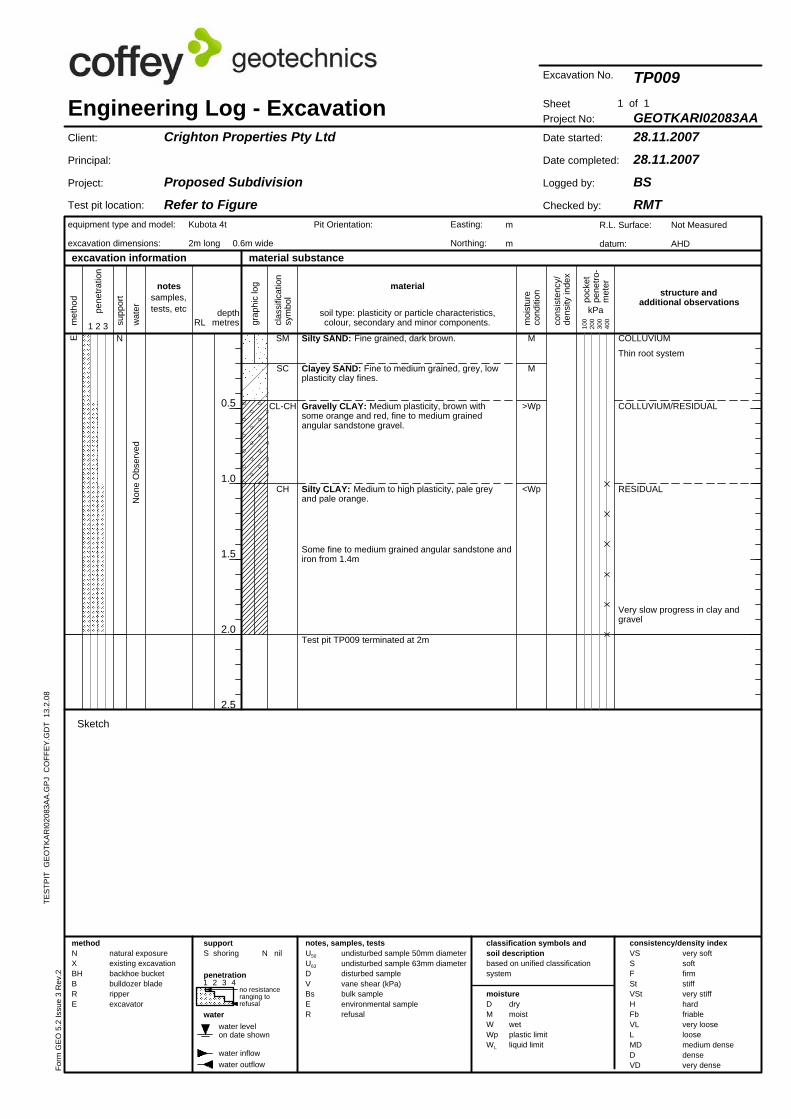
Very slow progress in clay andgravel
CH
CL-CH
SC
SME
water levelon date shown
TES
TPIT
GE
OTK
AR
I020
83A
A.G
PJ
CO
FFE
Y.G
DT
13.
2.08
Non
e O
bser
ved
kPa
N nil
1 of 1su
ppor
t
Test pit location:
1 2 3 4
cons
iste
ncy/
dens
ity in
dex
met
hod
VSSFStVStHFbVLLMDDVD
water
moisture
material substance
RESIDUAL
100
200
300
400
<Wp
>Wp
M
M
Test pit TP009 terminated at 2m
Some fine to medium grained angular sandstone andiron from 1.4m
Silty CLAY: Medium to high plasticity, pale greyand pale orange.
Gravelly CLAY: Medium plasticity, brown withsome orange and red, fine to medium grainedangular sandstone gravel.
Clayey SAND: Fine to medium grained, grey, lowplasticity clay fines.
Silty SAND: Fine grained, dark brown.
COLLUVIUM/RESIDUAL
Thin root system
COLLUVIUMN
moi
stur
eco
nditi
on
very softsoftfirmstiffvery stiffhardfriablevery looseloosemedium densedensevery dense
notes, samples, tests
equipment type and model:
excavation dimensions:
excavation information
clas
sific
atio
nsy
mbo
l
classification symbols andsoil descriptionbased on unified classificationsystem
material
wat
er depthmetres1 2 3
structure andadditional observations
notessamples,tests, etc
RL
Not Measured
AHD
Project No:
28.11.200728.11.2007
BSRMT
GEOTKARI02083AA
TP009
Date started:
Date completed:
Logged by:
Checked by:
Sheet
Client:
Principal:
Project:
Engineering Log - ExcavationCrighton Properties Pty Ltd
Proposed SubdivisionRefer to Figure
R.L. Surface:
datum:
Pit Orientation: Easting:
Northing:
supportS shoring
Kubota 4t
2m long 0.6m wide
water inflow
Sketch
drymoistwetplastic limitliquid limit
consistency/density index
water outflow
no resistanceranging torefusal
natural exposureexisting excavationbackhoe bucketbulldozer bladeripperexcavator
Excavation No.
pock
etpe
netro
-m
eter
grap
hic
log
pene
tratio
n
m
m
Form
GE
O 5
.2 Is
sue
3 R
ev.2
undisturbed sample 50mm diameterundisturbed sample 63mm diameterdisturbed samplevane shear (kPa)bulk sampleenvironmental samplerefusal
U50
U63
DVBsER
penetration
methodNXBHBRE D
MWWpWL
soil type: plasticity or particle characteristics,colour, secondary and minor components.
water inflow
cons
iste
ncy/
dens
ity in
dex
met
hod
VSSFStVStHFbVLLMDDVD
water
moisture1 2 3 4
100
200
300
400
0.5
1.0
1.5
2.0
2.5
material substance
Non
e O
bser
ved
drymoistwetplastic limitliquid limit
consistency/density index
water outflow
no resistanceranging torefusal
natural exposureexisting excavationbackhoe bucketbulldozer bladeripperexcavator
water levelon date shown
notessamples,tests, etc kPa
N nil
1 of 1su
ppor
t
Test pit location:
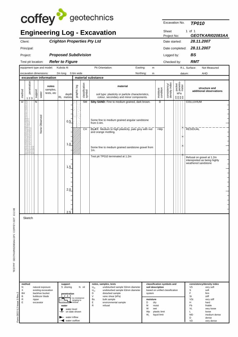
D
Test pit TP010 terminated at 1.2m
Some fine to medium grained sandstone gravel from1m.
CLAY: Medium to high plasticity, pale grey with redand orange mottling.
Some fine to medium grained angular sandstonefrom 0.4m.
Silty SAND: Fine to medium grained, dark brown.
>Wp
Kubota 4t
2m long 0.6m wide
CH
SME
Refusal on gravel at 1.2minterepreted as being highlyweathered sandstone
COLLUVIUMN
RESIDUAL
material
Engineering Log - Excavation
very softsoftfirmstiffvery stiffhardfriablevery looseloosemedium densedensevery dense
notes, samples, tests
equipment type and model:
excavation dimensions:
excavation information
TES
TPIT
GE
OTK
AR
I020
83A
A.G
PJ
CO
FFE
Y.G
DT
13.
2.08
classification symbols andsoil descriptionbased on unified classificationsystem
RLwat
er
moi
stur
eco
nditi
on
depthmetres1 2 3
Sketch
clas
sific
atio
nsy
mbo
l
Crighton Properties Pty Ltd
Proposed SubdivisionRefer to Figure
Project No:
28.11.200728.11.2007
BSRMT
GEOTKARI02083AA
TP010
Date started:
Date completed:
Logged by:
Checked by:
Sheet
R.L. Surface:
datum:
Not Measured
AHD
Client:
Principal:
Project:
structure andadditional observations
methodNXBHBRE D
MWWpWL
supportS shoring
Form
GE
O 5
.2 Is
sue
3 R
ev.2
Pit Orientation: Easting:
Northing:
penetration
U50
U63
DVBsER
pock
etpe
netro
-m
eter
grap
hic
log
pene
tratio
n
soil type: plasticity or particle characteristics,colour, secondary and minor components.
m
m
Excavation No.
undisturbed sample 50mm diameterundisturbed sample 63mm diameterdisturbed samplevane shear (kPa)bulk sampleenvironmental samplerefusal
water levelon date shown
cons
iste
ncy/
dens
ity in
dex
met
hod
VSSFStVStHFbVLLMDDVD
water
100
200
300
400
material substance
Test pit location:
0.5
1.0
1.5
2.0
2.5
Kubota 4t
2m long 0.6m wide
moisture
Non
e O
bser
ved
Sketch
drymoistwetplastic limitliquid limit
consistency/density index
water outflow
no resistanceranging torefusal
1 2 3 4
notessamples,tests, etc kPa
N nil
1 of 1su
ppor
t
natural exposureexisting excavationbackhoe bucketbulldozer bladeripperexcavator
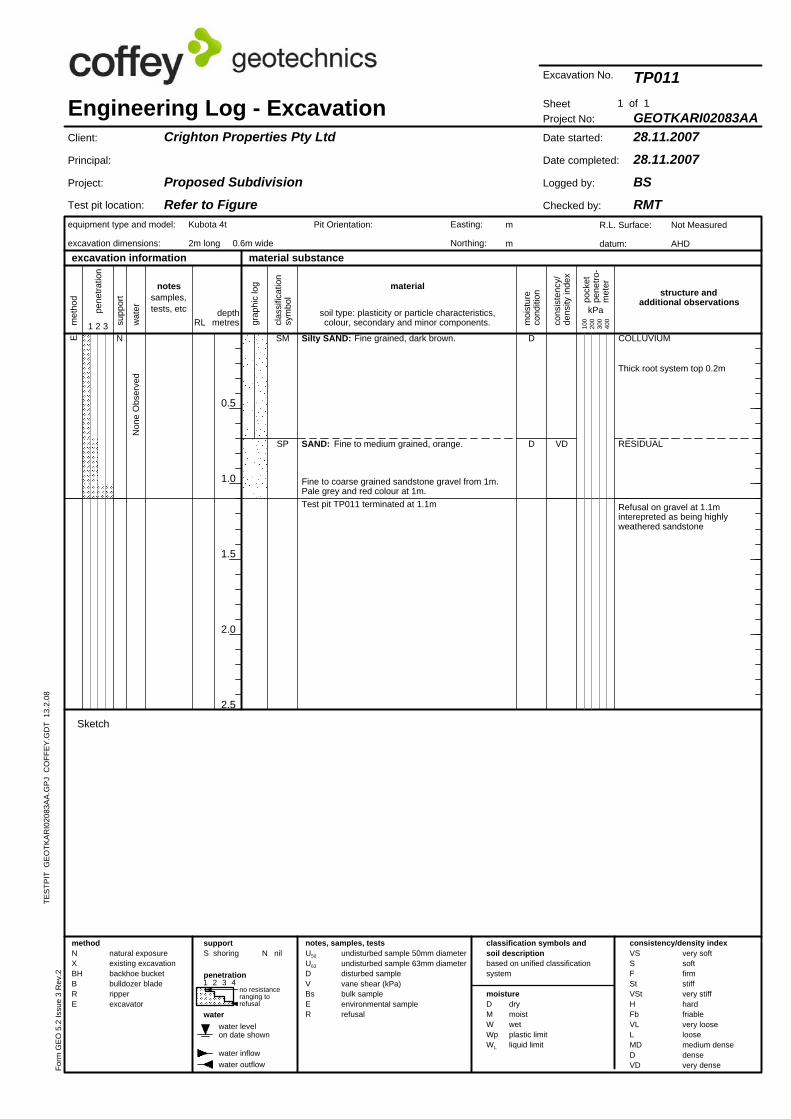
Test pit TP011 terminated at 1.1m
D
D
Fine to coarse grained sandstone gravel from 1m.Pale grey and red colour at 1m.
SAND: Fine to medium grained, orange.
Silty SAND: Fine grained, dark brown.
VD RESIDUALSP
SME
Refusal on gravel at 1.1minterepreted as being highlyweathered sandstone
Thick root system top 0.2m
COLLUVIUMN
classification symbols andsoil descriptionbased on unified classificationsystem
Engineering Log - Excavation
very softsoftfirmstiffvery stiffhardfriablevery looseloosemedium densedensevery dense
notes, samples, tests
equipment type and model:
excavation dimensions:
clas
sific
atio
nsy
mbo
lmaterial
RLwat
er
moi
stur
eco
nditi
on
depthmetres1 2 3
water inflow
excavation information
R.L. Surface:
datum:
Project No:
28.11.200728.11.2007
BSRMT
GEOTKARI02083AA
TP011
Date started:
Date completed:
Logged by:
Checked by:
Client:
Principal:
Project:
Crighton Properties Pty Ltd
Proposed SubdivisionRefer to Figure
Not Measured
AHD
Sheet
Easting:
Northing:
structure andadditional observations
U50
U63
DVBsER
penetration
methodNXBHBRE D
MWWpWL
supportS shoring
Pit Orientation:
Excavation No.
Form
GE
O 5
.2 Is
sue
3 R
ev.2
TES
TPIT
GE
OTK
AR
I020
83A
A.G
PJ
CO
FFE
Y.G
DT
13.
2.08
pock
etpe
netro
-m
eter
grap
hic
log
pene
tratio
n
soil type: plasticity or particle characteristics,colour, secondary and minor components.
m
m
undisturbed sample 50mm diameterundisturbed sample 63mm diameterdisturbed samplevane shear (kPa)bulk sampleenvironmental samplerefusal

CH
0.5
1.0
1.5
2.0
2.5
RESDIUALCH
CL
SME
TES
TPIT
GE
OTK
AR
I020
83A
A.G
PJ
CO
FFE
Y.G
DT
13.
2.08
cons
iste
ncy/
dens
ity in
dex
Non
e O
bser
ved
kPa
N nil
1 of 1su
ppor
t
Test pit location:
100
200
300
400
water levelon date shown
met
hod
VSSFStVStHFbVLLMDDVD
water
moisture
material substance
COLLUVIUM/RESIDUAL
1 2 3 4
CLAY: Medium to high plasticity, pale grey andorange and red mottling, some silt.
<=Wp
<Wp
D
Refusal on sandstone in northernend of TP at 1.6m
Silty CLAY: High plasticity, pale grey with some redand orange mottling.
Gravelly CLAY: Low to medium plasticity, dark red,fine grained angular gravel.
Silty SAND: Fine grained, brown, some fine tomedium grained angular gravel.
VSt/H
VSt/H
Test pit TP012 terminated at 1.6m
COLLUVIUMN
<<Wp
moi
stur
eco
nditi
on
very softsoftfirmstiffvery stiffhardfriablevery looseloosemedium densedensevery dense
notes, samples, tests
equipment type and model:
excavation dimensions:
excavation information
clas
sific
atio
nsy
mbo
l
classification symbols andsoil descriptionbased on unified classificationsystem
material
wat
er depthmetres1 2 3
structure andadditional observations
notessamples,tests, etc
RL
Not Measured
AHD
Project No:
29.11.200729.11.2007
BSRMT
GEOTKARI02083AA
TP012
Date started:
Date completed:
Logged by:
Checked by:
Sheet
Client:
Principal:
Project:
Engineering Log - ExcavationCrighton Properties Pty Ltd
Proposed SubdivisionRefer to Figure
R.L. Surface:
datum:
Easting:
Northing:
Form
GE
O 5
.2 Is
sue
3 R
ev.2
supportS shoring
Kubota 4t
2m long 0.6m wide
water inflow
Sketch
drymoistwetplastic limitliquid limit
consistency/density index
water outflow
no resistanceranging torefusal
natural exposureexisting excavationbackhoe bucketbulldozer bladeripperexcavator
m
m
pock
etpe
netro
-m
eter
grap
hic
log
pene
tratio
n
Pit Orientation:
soil type: plasticity or particle characteristics,colour, secondary and minor components.
Excavation No.
undisturbed sample 50mm diameterundisturbed sample 63mm diameterdisturbed samplevane shear (kPa)bulk sampleenvironmental samplerefusal
U50
U63
DVBsER
penetration
methodNXBHBRE D
MWWpWL
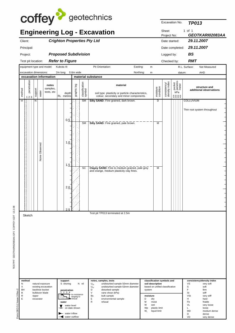
material substance
100
200
300
400
1 2 3 4
water levelon date shown
cons
iste
ncy/
dens
ity in
dex
met
hod
VSSFStVStHFbVLLMDDVD
TES
TPIT
GE
OTK
AR
I020
83A
A.G
PJ
CO
FFE
Y.G
DT
13.
2.08
moisture
1 of 1
water
Kubota 4t
2m long 0.6m wide
Non
e O
bser
ved
Sketch
drymoistwetplastic limitliquid limit
consistency/density index
water outflow
Test pit location:
natural exposureexisting excavationbackhoe bucketbulldozer bladeripperexcavator
supp
ort
notessamples,tests, etc kPa
N nil
no resistanceranging torefusal
0.5
1.0
1.5
2.0
2.5
M
D
Test pit TP013 terminated at 2.5m
Clayey SAND: Fine to medium grained, pale greyand orange, medium plasticity clay fines.
Silty SAND: Fine grained, pale brown.
Silty SAND: Fine grained, dark brown.
M
E
SC
SM
Thin root system throughout
COLLUVIUMN
SM
classification symbols andsoil descriptionbased on unified classificationsystem
Engineering Log - Excavation
very softsoftfirmstiffvery stiffhardfriablevery looseloosemedium densedensevery dense
notes, samples, tests
equipment type and model:
excavation dimensions:
clas
sific
atio
nsy
mbo
lmaterial
RLwat
er
moi
stur
eco
nditi
on
depthmetres
water inflow
structure andadditional observations
excavation information
R.L. Surface:
datum:
Project No:
29.11.200729.11.2007
BSRMT
GEOTKARI02083AA
TP013
Date started:
Date completed:
Logged by:
Checked by:
Client:
Principal:
Project:
Crighton Properties Pty Ltd
Proposed SubdivisionRefer to Figure
Not Measured
AHD
Sheet
Form
GE
O 5
.2 Is
sue
3 R
ev.2
1 2 3
undisturbed sample 50mm diameterundisturbed sample 63mm diameterdisturbed samplevane shear (kPa)bulk sampleenvironmental samplerefusal
U50
U63
DVBsER
penetration
methodNXBHBRE
supportS shoring
m
m
Pit Orientation: Easting:
Northing:
DMWWpWL
Excavation No.
pock
etpe
netro
-m
eter
grap
hic
log
pene
tratio
n
soil type: plasticity or particle characteristics,colour, secondary and minor components.
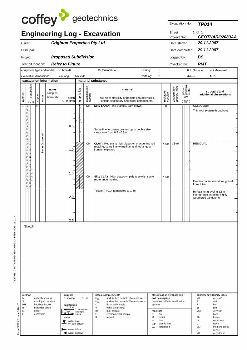
SME
Refusal on gravel at 1.8minterepreted as being highlyweathered sandstone
Fine to coarse sandstone gravelfrom 1.7m
RESIDUAL
COLLUVIUMN
Thin root system throughout
met
hod
water
moisture
material substance
CH
CH
0.5
1.0
1.5
2.0
2.5
Date started:
Date completed:
Logged by:
Checked by:
VSt/H
Non
e O
bser
ved
TES
TPIT
GE
OTK
AR
I020
83A
A.G
PJ
CO
FFE
Y.G
DT
13.
2.08
Project No:
29.11.200729.11.2007
BSRMT
TP014
Silty SAND: Fine grained, dark brown.
Sheet
Client:
Principal:
Project:
R.L. Surface:
datum:
Crighton Properties Pty Ltd
Proposed SubdivisionRefer to Figure
Not Measured
AHD
GEOTKARI02083AA
D
<Wp
Test pit TP014 terminated at 1.8m
Silty CLAY: High plasticity, pale grey with somered-orange mottling.
CLAY: Medium to high plasticity, orange and redmottling, some fine to medium grained angularironstone gravel.
Some fine to coarse grained up to cobble sizesandstone from 0.5 - 0.8m.
cons
iste
ncy/
dens
ity in
dex
<Wp
pock
etpe
netro
-m
eter
grap
hic
log
pene
tratio
n
soil type: plasticity or particle characteristics,colour, secondary and minor components.
m
m
VSSFStVStHFbVLLMDDVD
material
Engineering Log - Excavation
very softsoftfirmstiffvery stiffhardfriablevery looseloosemedium densedensevery dense
notes, samples, tests
equipment type and model:
excavation dimensions:
excavation information
classification symbols andsoil descriptionbased on unified classificationsystem
RLwat
er
moi
stur
eco
nditi
on
depthmetres1 2 3
structure andadditional observations
U50
U63
DVBsER
clas
sific
atio
nsy
mbo
l
water levelon date shown
drymoistwetplastic limitliquid limit
consistency/density index
water outflow
no resistanceranging torefusal
natural exposureexisting excavationbackhoe bucketbulldozer bladeripperexcavator
water inflow
Kubota 4t
2m long 0.6m wide
notessamples,tests, etc kPa
N nil
1 of 1su
ppor
t
Test pit location:
100
200
300
400
1 2 3 4
Excavation No.
penetration
methodNXBHBRE D
MWWpWL
supportS shoring
Form
GE
O 5
.2 Is
sue
3 R
ev.2
Pit Orientation:
Sketch
undisturbed sample 50mm diameterundisturbed sample 63mm diameterdisturbed samplevane shear (kPa)bulk sampleenvironmental samplerefusal
Easting:
Northing:
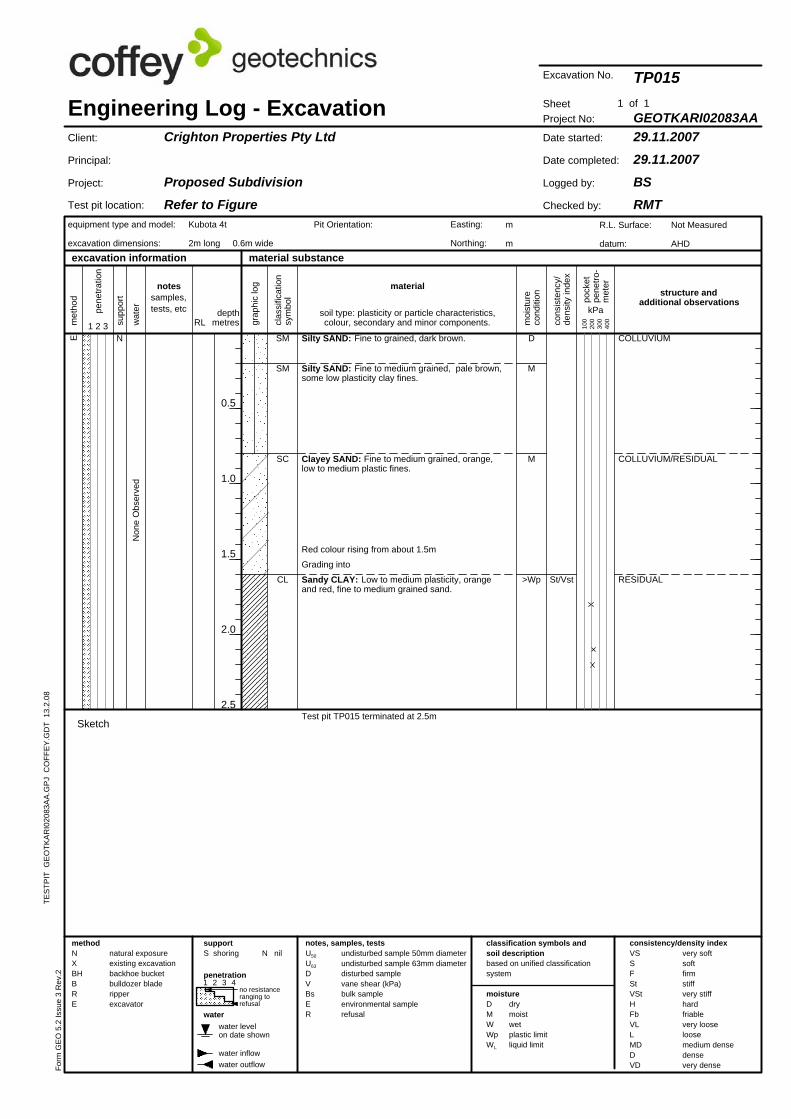
0.5
1.0
1.5
2.0
2.5
CL
SC
SM
SME
TES
TPIT
GE
OTK
AR
I020
83A
A.G
PJ
CO
FFE
Y.G
DT
13.
2.08
100
200
300
400
Non
e O
bser
ved
notessamples,tests, etc kPa
N nil
1 of 1
Test pit location:
1 2 3 4
water levelon date shown
cons
iste
ncy/
dens
ity in
dex
met
hod
VSSFStVStHFbVLLMDDVD
water
moisture
material substance
supp
ort
Grading into
M
D
>WpSandy CLAY: Low to medium plasticity, orangeand red, fine to medium grained sand.
Red colour rising from about 1.5m
Clayey SAND: Fine to medium grained, orange,low to medium plastic fines.
Silty SAND: Fine to medium grained, pale brown,some low plasticity clay fines.
Silty SAND: Fine to grained, dark brown.
St/Vst
Test pit TP015 terminated at 2.5m
RESIDUAL
COLLUVIUM/RESIDUAL
COLLUVIUMN
M
wat
er
natural exposureexisting excavationbackhoe bucketbulldozer bladeripperexcavator
very softsoftfirmstiffvery stiffhardfriablevery looseloosemedium densedensevery dense
notes, samples, tests
equipment type and model:
excavation dimensions:
excavation information
clas
sific
atio
nsy
mbo
l
classification symbols andsoil descriptionbased on unified classificationsystem
RL moi
stur
eco
nditi
on
depthmetres1 2 3
structure andadditional observations
material
Crighton Properties Pty Ltd
Proposed SubdivisionRefer to Figure
Project No:
29.11.200729.11.2007
BSRMT
GEOTKARI02083AA
TP015
Date started:
Date completed:
Logged by:
Checked by:
SheetEngineering Log - Excavation
R.L. Surface:
datum:
Not Measured
AHD
Client:
Principal:
Project:
Form
GE
O 5
.2 Is
sue
3 R
ev.2
Pit Orientation: Easting:
Northing:
methodNXBHBRE
Kubota 4t
2m long 0.6m wide
water inflow
Sketch
drymoistwetplastic limitliquid limit
consistency/density index
water outflow
no resistanceranging torefusal
soil type: plasticity or particle characteristics,colour, secondary and minor components.
pock
etpe
netro
-m
eter
grap
hic
log
supportS shoring
pene
tratio
n
DMWWpWL
m
m
Excavation No.
undisturbed sample 50mm diameterundisturbed sample 63mm diameterdisturbed samplevane shear (kPa)bulk sampleenvironmental samplerefusal
U50
U63
DVBsER
penetration
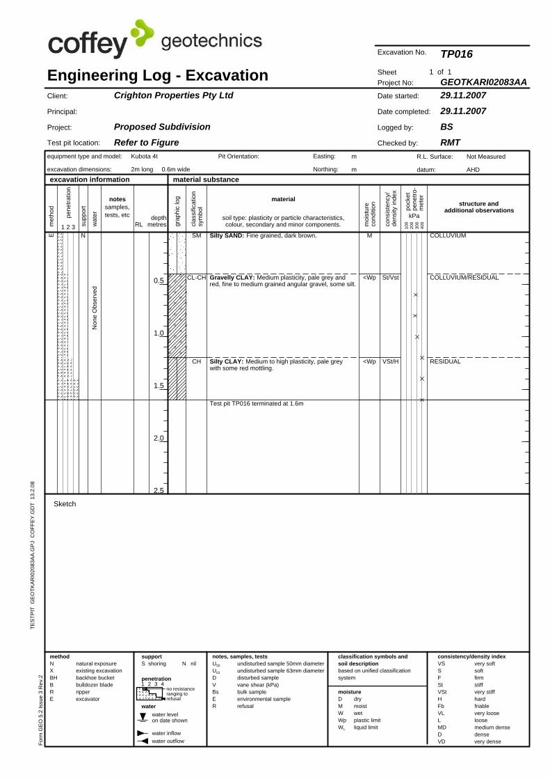
0.5
1.0
1.5
2.0
2.5
material substance
CH
CL-CH
SME
TES
TPIT
GE
OTK
AR
I020
83A
A.G
PJ
CO
FFE
Y.G
DT
13.
2.08
Test pit location:
Non
e O
bser
ved
notessamples,tests, etc kPa
N nil
supp
ort
RESIDUAL
100
200
300
400
1 2 3 4
water levelon date shown
cons
iste
ncy/
dens
ity in
dex
met
hod
VSSFStVStHFbVLLMDDVD
water
moisture
1 of 1
Silty CLAY: Medium to high plasticity, pale greywith some red mottling.
<Wp
<Wp
M
Test pit TP016 terminated at 1.6m
Gravelly CLAY: Medium plasticity, pale grey andred, fine to medium grained angular gravel, some silt.
Silty SAND: Fine grained, dark brown.
VSt/H
St/Vst COLLUVIUM/RESIDUAL
COLLUVIUMN
natural exposureexisting excavationbackhoe bucketbulldozer bladeripperexcavator
wat
er
no resistanceranging torefusal
very softsoftfirmstiffvery stiffhardfriablevery looseloosemedium densedensevery dense
notes, samples, tests
equipment type and model:
excavation dimensions:
excavation information
clas
sific
atio
nsy
mbo
l
classification symbols andsoil descriptionbased on unified classificationsystem
RL moi
stur
eco
nditi
on
depthmetres1 2 3
structure andadditional observations
material
Crighton Properties Pty Ltd
Proposed SubdivisionRefer to Figure
Project No:
29.11.200729.11.2007
BSRMT
GEOTKARI02083AA
TP016
Date started:
Date completed:
Logged by:
Checked by:
SheetEngineering Log - Excavation
R.L. Surface:
datum:
Not Measured
AHD
Client:
Principal:
Project:
Form
GE
O 5
.2 Is
sue
3 R
ev.2
Pit Orientation: Easting:
Northing:
methodNXBHBRE
Kubota 4t
2m long 0.6m wide
water inflow
Sketch
drymoistwetplastic limitliquid limit
consistency/density index
water outflow
soil type: plasticity or particle characteristics,colour, secondary and minor components.
pock
etpe
netro
-m
eter
supportS shoring
pene
tratio
n
DMWWpWL
m
m
Excavation No.
undisturbed sample 50mm diameterundisturbed sample 63mm diameterdisturbed samplevane shear (kPa)bulk sampleenvironmental samplerefusal
U50
U63
DVBsER
penetration
grap
hic
log
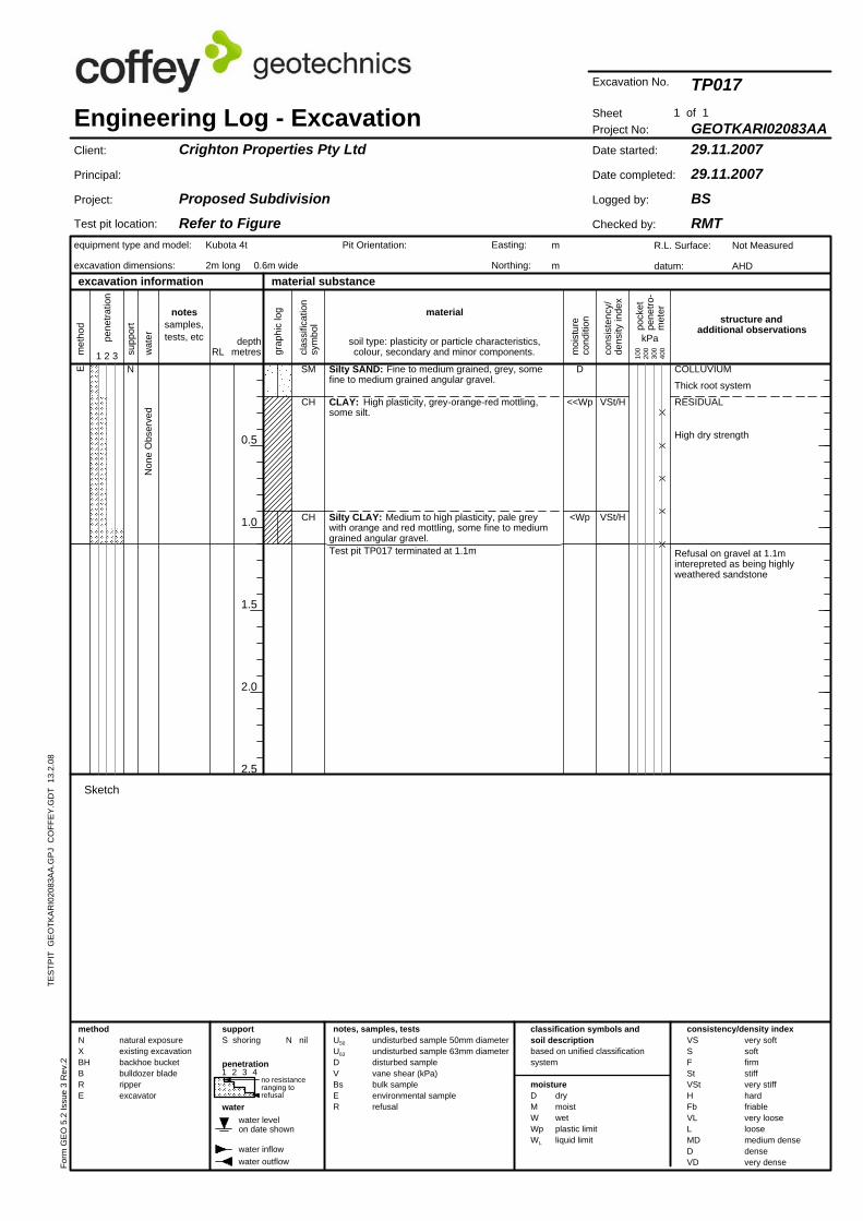
<Wp
<<Wp
D
TES
TPIT
GE
OTK
AR
I020
83A
A.G
PJ
CO
FFE
Y.G
DT
13.
2.08
Test pit TP017 terminated at 1.1m
Silty CLAY: Medium to high plasticity, pale greywith orange and red mottling, some fine to mediumgrained angular gravel.
CLAY: High plasticity, grey-orange-red mottling,some silt.
Silty SAND: Fine to medium grained, grey, somefine to medium grained angular gravel.
High dry strength
RESIDUAL
Thick root system
COLLUVIUM
VSt/H
N
water inflow
Kubota 4t
2m long 0.6m wide
Sketch
drymoistwetplastic limitliquid limit
consistency/density index
water outflow
no resistanceranging torefusal
natural exposureexisting excavationbackhoe bucketbulldozer bladeripperexcavator
undisturbed sample 50mm diameterundisturbed sample 63mm diameterdisturbed samplevane shear (kPa)bulk sampleenvironmental samplerefusal
Non
e O
bser
ved
pock
etpe
netro
-m
eter
grap
hic
log
pene
tratio
n
soil type: plasticity or particle characteristics,colour, secondary and minor components.
Excavation No.
VSt/H
U50
U63
DVBsER
penetration
methodNXBHBRE D
MWWpWL
supportS shoring
Form
GE
O 5
.2 Is
sue
3 R
ev.2
Pit Orientation: Easting:
Northing:
m
m
moi
stur
eco
nditi
on
very softsoftfirmstiffvery stiffhardfriablevery looseloosemedium densedensevery dense
notes, samples, tests
equipment type and model:
excavation dimensions:
excavation information
clas
sific
atio
nsy
mbo
l
classification symbols andsoil descriptionbased on unified classificationsystem
material
Refusal on gravel at 1.1minterepreted as being highlyweathered sandstone
wat
er depthmetres1 2 3
structure andadditional observations
RL
Not Measured
AHD
Project No:
29.11.200729.11.2007
BSRMT
GEOTKARI02083AA
TP017
Date started:
Date completed:
Logged by:
Checked by:
Sheet
Client:
Principal:
Project:
Engineering Log - ExcavationCrighton Properties Pty Ltd
Proposed SubdivisionRefer to Figure
R.L. Surface:
datum:material substance
moisture
0.5
1.0
1.5
2.0
2.5
water
CH
CH
SM
supp
ort
E
notessamples,tests, etc kPa
1 of 1
Test pit location:
100
200
300
400
1 2 3 4
water levelon date shown
cons
iste
ncy/
dens
ity in
dex
met
hod
VSSFStVStHFbVLLMDDVD
N nil
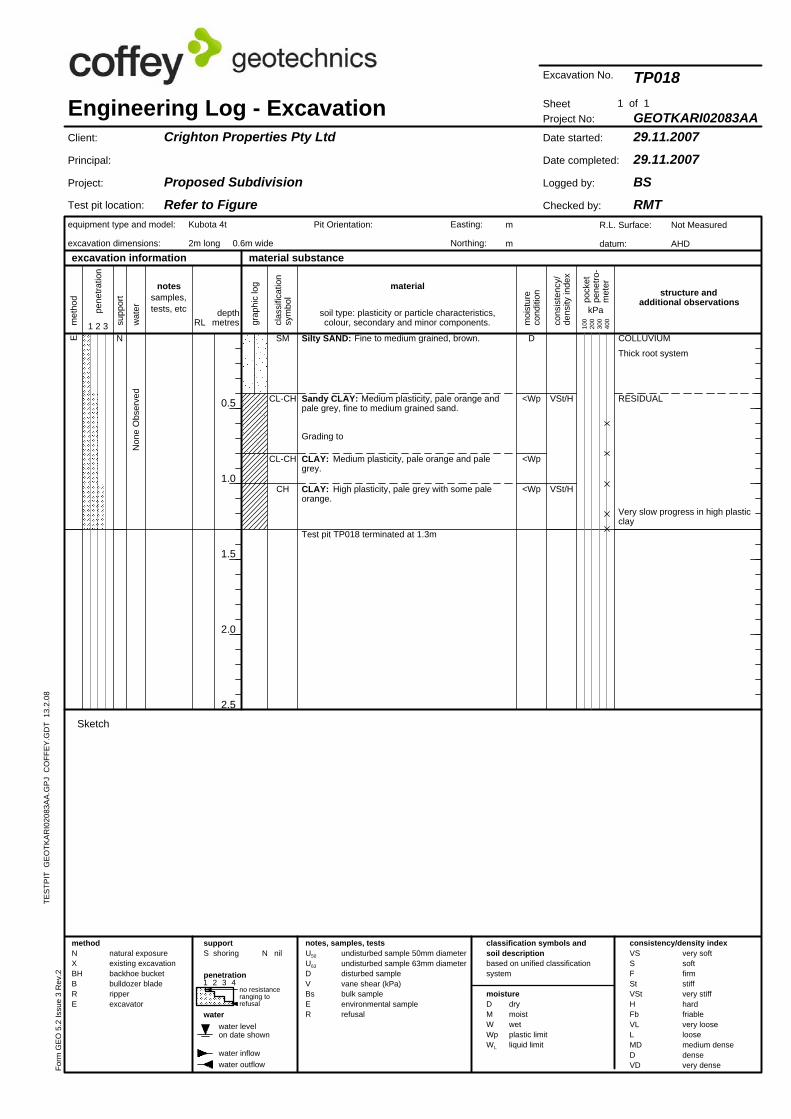
CH
0.5
1.0
1.5
2.0
2.5
CL-CH
CL-CH
SME
Very slow progress in high plasticclay
RESIDUAL
cons
iste
ncy/
dens
ity in
dex
TES
TPIT
GE
OTK
AR
I020
83A
A.G
PJ
CO
FFE
Y.G
DT
13.
2.08
notessamples,tests, etc
Non
e O
bser
ved
N nil
1 of 1su
ppor
t
Test pit location:
100
200
300
400
water levelon date shown
met
hod
VSSFStVStHFbVLLMDDVD
water
moisture
material substance
1 2 3 4
Grading to
Thick root system
<Wp
D
Test pit TP018 terminated at 1.3m
<Wp
CLAY: Medium plasticity, pale orange and palegrey.
Sandy CLAY: Medium plasticity, pale orange andpale grey, fine to medium grained sand.
Silty SAND: Fine to medium grained, brown.
VSt/H
VSt/H
CLAY: High plasticity, pale grey with some paleorange.
N
<Wp
COLLUVIUM
moi
stur
eco
nditi
on
very softsoftfirmstiffvery stiffhardfriablevery looseloosemedium densedensevery dense
notes, samples, tests
equipment type and model:
excavation dimensions:
excavation information
clas
sific
atio
nsy
mbo
l
classification symbols andsoil descriptionbased on unified classificationsystem
material
wat
er depthmetres1 2 3
structure andadditional observations
kPaRL
Not Measured
AHD
Project No:
29.11.200729.11.2007
BSRMT
GEOTKARI02083AA
TP018
Date started:
Date completed:
Logged by:
Checked by:
Sheet
Client:
Principal:
Project:
Engineering Log - ExcavationCrighton Properties Pty Ltd
Proposed SubdivisionRefer to Figure
R.L. Surface:
datum:
Easting:
Northing:
Form
GE
O 5
.2 Is
sue
3 R
ev.2
supportS shoring
Kubota 4t
2m long 0.6m wide
water inflow
Sketch
drymoistwetplastic limitliquid limit
consistency/density index
water outflow
no resistanceranging torefusal
natural exposureexisting excavationbackhoe bucketbulldozer bladeripperexcavator
m
m
pock
etpe
netro
-m
eter
grap
hic
log
pene
tratio
n
Pit Orientation:
soil type: plasticity or particle characteristics,colour, secondary and minor components.
Excavation No.
undisturbed sample 50mm diameterundisturbed sample 63mm diameterdisturbed samplevane shear (kPa)bulk sampleenvironmental samplerefusal
U50
U63
DVBsER
penetration
methodNXBHBRE D
MWWpWL
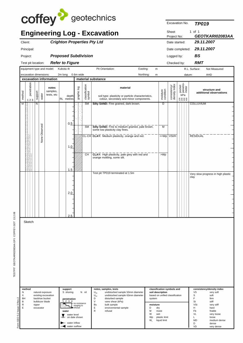
0.5
1.0
1.5
2.0
2.5
SM
water
CH
CL-CH
TES
TPIT
GE
OTK
AR
I020
83A
A.G
PJ
CO
FFE
Y.G
DT
13.
2.08
supp
ort
natural exposureexisting excavationbackhoe bucketbulldozer bladeripperexcavator
Non
e O
bser
ved
notessamples,tests, etc kPa
material substance
1 of 1
moisture
Test pit location:
100
200
300
400
1 2 3 4
water levelon date shown
cons
iste
ncy/
dens
ity in
dex
met
hod
VSSFStVStHFbVLLMDDVD
E
N nil
CLAY: High plasticity, pale grey with red andorange mottling, some silt.
>Wp
<=Wp
M
D
SM
Test pit TP019 terminated at 1.5m
CLAY: Medium plasticity, orange and red.
Silty SAND: Fine to medium grained, pale brown,some low plasticity clay fines.
Silty SAND: Fine grained, dark brown.
VSt/H
Very slow progress in high plasticclay
RESIDUAL
COLLUVIUMN
no resistanceranging torefusal
wat
er
Engineering Log - Excavation
very softsoftfirmstiffvery stiffhardfriablevery looseloosemedium densedensevery dense
notes, samples, tests
equipment type and model:
excavation dimensions:
excavation information
clas
sific
atio
nsy
mbo
l
classification symbols andsoil descriptionbased on unified classificationsystem
water outflow
RL moi
stur
eco
nditi
on
depthmetres1 2 3
structure andadditional observations
material
Crighton Properties Pty Ltd
Proposed SubdivisionRefer to Figure
Project No:
29.11.200729.11.2007
BSRMT
GEOTKARI02083AA
TP019
Date started:
Date completed:
Logged by:
Checked by:
Sheet
R.L. Surface:
datum:
Not Measured
AHD
Client:
Principal:
Project:
supportS shoring
Form
GE
O 5
.2 Is
sue
3 R
ev.2
Pit Orientation: Easting:
Northing:
methodNXBHBRE
penetration
Kubota 4t
2m long 0.6m wide
water inflow
Sketch
drymoistwetplastic limitliquid limit
consistency/density index
pene
tratio
n
DMWWpWL
grap
hic
log
soil type: plasticity or particle characteristics,colour, secondary and minor components.
m
m
Excavation No.
undisturbed sample 50mm diameterundisturbed sample 63mm diameterdisturbed samplevane shear (kPa)bulk sampleenvironmental samplerefusal
U50
U63
DVBsER
pock
etpe
netro
-m
eter
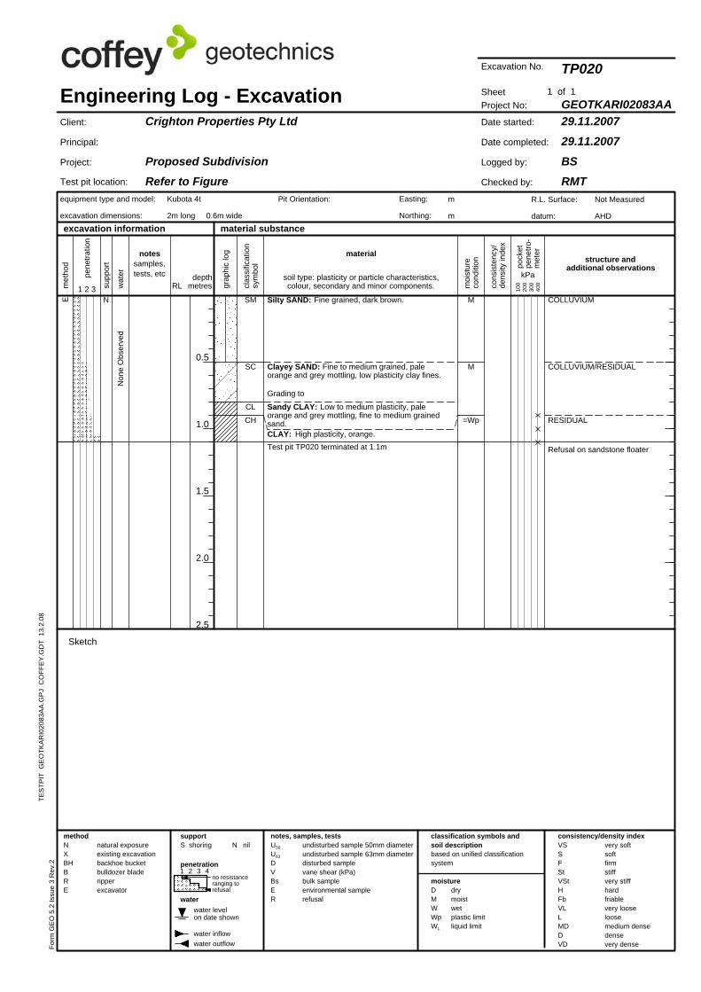
0.5
1.0
1.5
2.0
2.5
TES
TPIT
GE
OTK
AR
I020
83A
A.G
PJ
CO
FFE
Y.G
DT
13.
2.08
moisture
CH
CL
SC
SM
Test pit location:
Non
e O
bser
ved
notessamples,tests, etc kPa
N nil
supp
ort
material substance
100
200
300
400
1 2 3 4
water levelon date shown
cons
iste
ncy/
dens
ity in
dex
met
hod
VSSFStVStHFbVLLMDDVD
water
1 of 1
E
=Wp
M
M
Test pit TP020 terminated at 1.1mCLAY: High plasticity, orange.
Sandy CLAY: Low to medium plasticity, paleorange and grey mottling, fine to medium grainedsand.
Grading to
Clayey SAND: Fine to medium grained, paleorange and grey mottling, low plasticity clay fines.
Silty SAND: Fine grained, dark brown.
natural exposureexisting excavationbackhoe bucketbulldozer bladeripperexcavator
Refusal on sandstone floater
RESIDUAL
COLLUVIUM/RESIDUAL
COLLUVIUMN
wat
er
very softsoftfirmstiffvery stiffhardfriablevery looseloosemedium densedensevery dense
notes, samples, tests
equipment type and model:
excavation dimensions:
excavation information
clas
sific
atio
nsy
mbo
l
classification symbols andsoil descriptionbased on unified classificationsystem
RL moi
stur
eco
nditi
on
depthmetres1 2 3
structure andadditional observations
no resistanceranging torefusal
material
Crighton Properties Pty Ltd
Proposed SubdivisionRefer to Figure
Project No:
29.11.200729.11.2007
BSRMT
GEOTKARI02083AA
TP020
Date started:
Date completed:
Logged by:
Checked by:
SheetEngineering Log - Excavation
R.L. Surface:
datum:
Not Measured
AHD
Client:
Principal:
Project:
Form
GE
O 5
.2 Is
sue
3 R
ev.2
Pit Orientation: Easting:
Northing:
supportS shoring
DMWWpWL
Kubota 4t
2m long 0.6m wide
water inflow
Sketch
drymoistwetplastic limitliquid limit
consistency/density index
water outflow
soil type: plasticity or particle characteristics,colour, secondary and minor components.
pock
etpe
netro
-m
eter
pene
tratio
n
m
m
Excavation No.
undisturbed sample 50mm diameterundisturbed sample 63mm diameterdisturbed samplevane shear (kPa)bulk sampleenvironmental samplerefusal
U50
U63
DVBsER
penetration
methodNXBHBRE
grap
hic
log
Appendix B Laboratory Results
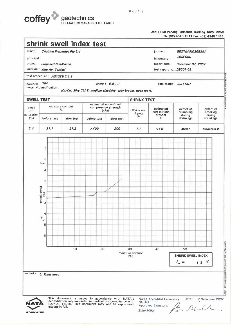
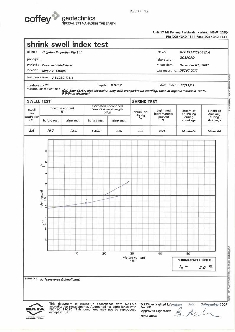
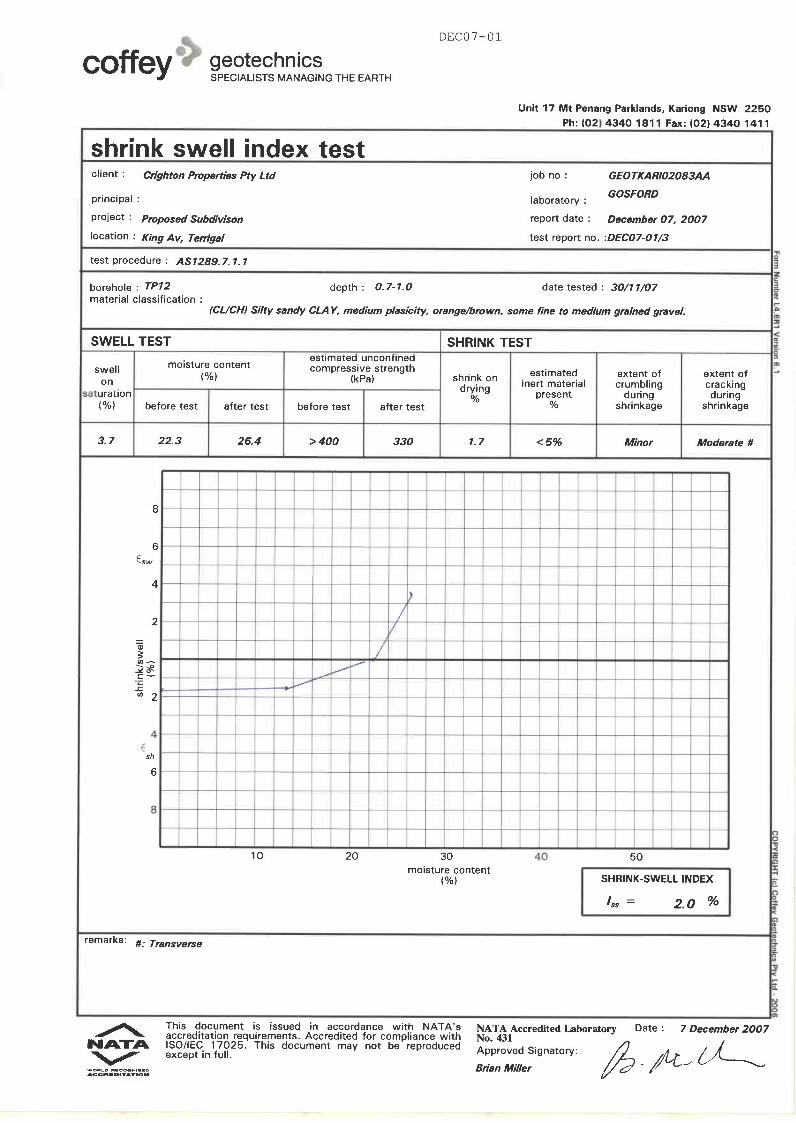
Appendix C Copy of reports GO540/1-AB and GO652/1-AB
6b
CRIGHTON PROPERTIES PT¥ LTDPROPOSED SUBDIVISION
LOT 22 KARALTA ROAD, PART PORTION 104TERRI GAL
GEOTECHNICAL ASSESSMENTREPORT" NO.G0540/1-AB i-lARCH,1992
COfFIYIEl
Coffey Partners International Pty Ltd Consulting Engineersin the Geotechnical Sciences
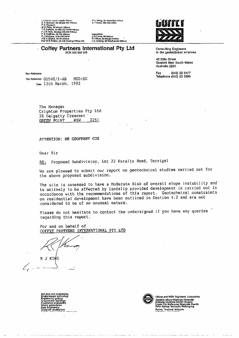
I n omll;'n. C.pt,;E f,I",pp$e; FIEAullG )( Spencer. oe: M£ngSc PhD MIEAustPC ThomsonM G Philp, BEMEngS< I.IIEA•••TO Sullivan, BA MSt ole FAlMMMIC:"",slP J N Poll •• BSc(Enlll.lS< ole """"',,P G Redman. BEpnD M'E"""P J Hil.hco~. "CIS I.Im" AlII ...J W A Gila •• , AM BE 1,"EAu"P,o' IiG Poulos. BEPhO DS«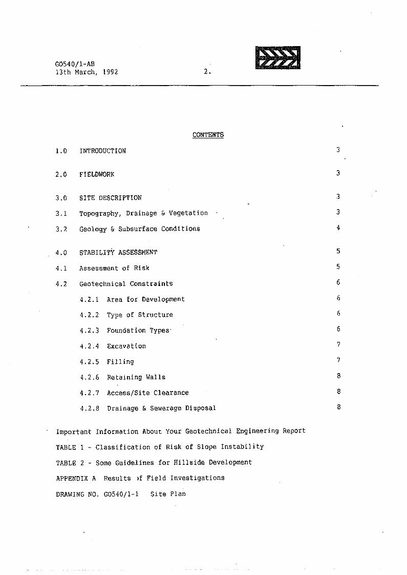
G0540/1-AB13th Narch, 1992 2. &ml
CONTENTS1.0 INTRODUCTION 3
2.0 FIELDWORK 3
3.0 SITE DESCRIPTION 3
3.1 Topography, Drainage & Vegetation 3
43.2 Geology & Subsurface Conditions
4.0 STABILITY ASSESSMENT 5
4.1 Assessment of Risk 5
4.2 Geotechnical Constraints 6
4.2.1 Rrea for Development 6
4.2.2 Type of Structure 6
4.2.3 Foundation Types' 6
4.2.4 Excavation 7
4.2.5 Fi 11 ing 7
4.2.6 Retaining Walls a
4.2.8 Drainage & Sewerage Disposal
8
8
4.2.7 Access/Site Clearance
Important Information About Your Geotechnical Engineering ReportTABLE 1 - Classification of Risk of Slope InstabilityTABLE 2 - Some Guidelines for Hillside DevelopmentAPPENDIX A Results )f Field Investigations
DRAWING NO. G0540/1-1 Site Plan
G0540/l-AB13th March, 1992 3. &mJ
1.0 INTRODUCTIONThis report presents an assessment of slope stability carried out for CrightonProperties Pty Ltd on Lot 22 (Part Portion 104) Karalta Road, Terrigal. Thework was commissioned by Mr Geoffery Cox of Crighton Properties Pty Ltd. A1:900 scale contour plan of the lot was provided by Cahill & Cameron Pty Ltd.It is understood that development plans have not been finalised for the site.However, it is understood to be likely that development will includeresidential allotments on moderately steep portions of the site, several largelakes with adjacent residential construction in low lying generally flatportions of the site and possibly terraced/split level units on the steeperportions of the site. It is also understood that roads are to be alignedgenerally across hillslopes on the steeper areas of the site.This report assesses the suitability of the lot for development from ageotechnical Viewpoint, provides a risk assessment in relation to slopestability and provides geotechnical constraints for development.2.0 FIELDWORKField work initially involved a walk-over survey/site appraisal by a SeniorEngineering Geologist on the 26th February, 1992, in which surface featureswere mapped. Utilising this information a program of test pitting was carriedout on the 3rd March, 1992 by a Geotechnical Engineer to assess subsurfaceprofiles.Eleven test pits (TPI to TPll) were excavated to depths ranging from 1.5m to3.4m by a rubber tyred backhoe. The apprOXimate location of the test pits isshown on Drawing No.G0540jl-l, together with the results of surface mapping.Test pit levels have been interpolated from the contour plan (A.HoD.).Engineering Logs of the test pits are presented in Appendix A, together withexplanation sheets defining the terms and symbols used.Groundwater conditions were noted at the time of field work in test pits whichwere open only for a short time. Variations may occur due to fluctuations inrainfall, temperature and other factors.3.0 SITE DESCRIPTION3.1 Topography, Drainage & VegetationTopographically, the lot is situated in an area of moderate to steeplyundulating terrain on the north-eastern en~ of a prominent south-west trendingridgeline. A secondary rounded spur/ridge',ine forms the eastern siteboundary.
G0540il-AB13th March, 1992 4. ImlI
Valley formation along two incised gullies has resulted in the existing sitelandform. Two prominent gullies originate at the upper slopes of the aboveridgeline and fall to the northinorth-east to join in the central part of thesite. The combined watercourse discharges to the north of the site, into abroad flat watercourse that drains to the east towards Duffy's Road.Valley side slopes across the site are convex in profile with surface slopesgenerally 10° over the upper slopes increasing up to 15° over the lowerslopes. Surface slopes of 5° to 9° occur along the crest and upper slopes ofthe ridgeline that trends along the eastern lot boundary. The base of theabove valley side slopes are characterised by;
* Flat alluvial areas of surface slope less than 3° adjacent to thewatercourses across the central to northern part of the site. Thetransition from the valley side slopes to the flat alluvial areas ismarked by a sharp concave slope break, or
* Steep gully side slopes ranging from 25° to 35°. The gullies areV-shaped in profile and are incised up to a~ estimated 5m to 6m indepth.
The site has been undersrcubbed with vegetation currently comprising mainlygrasses with a sparse to moderate cover of mature eucalypts. The gullies andgully sides are generally covered with thiCK vegetation which includes palmsand lantana.Existing development on the site comprises a transmission easement along theeastern boundary and two small "farm" dams at the confluence of the twowatercourses. The dams have been breached during recent heavy rain, mostlikely the result of piping at the contact between earth" embankment and600mmdiameter concrete overflow pipes. A unfor-med section of Karal ta Road runsalong the northern site boundary.3.2 Geology & Subsurface ConditionsGeologically, the site is situated in the Triassic Age Gosford Formation whichis characterised by sandstone (often lithic) and siltstone rock types.On the basis of surface features and subsurface conditions encountered in thetest pits. the site can be divided into two units. namely
* UNIT A - comprising predominately residual soils overlyingsandstone/siltstone rock at about 1m to 1.5m depth,
* UNIT B - comprising deep alluvial soils up to or g--eater than 3.5m indepth.
G0540/1-AB13th Narch, 1992 5. &mI
The approximate extent of the above units is shown on Drawing No.G0540il-1.The subsurface profile. encountered within Unit A (Test Pits 1,2,3,5,6,7 and11) can be summarised as follows;
* TOPSOIL: Comprising Silty SAND to depths ranging Erom a.25m toO.Sm; fine to coarse grained, with some gravel, moist.overlying
*' SI.QPEWASH: Where encountered, comprising Gravelly Sandy CLAY of lowplasticity and Gravelly Clayey SAND to depths generally ofO.5m and locally up to O~9m, moist, overlying
* RESIDUAL: Comprising CLAY, Sandy CLAY and Gravelly Sandy CLAY todepths ranging from 1.1m to 2.0m, medium to highplasticity, with some sandstone rock fragments, estimatedvery stiff to hard consistency, overlying
* ROCK: Comprising SANDSTONE and SILTSTONE, extremely to highlyweathered. Backhoe refusal on sandstone was encounteredin Test Pits 1,5,6,7 and 11 at depths ranging from 1.5m to2.8m.
The subsurface profile encountered within Unit B ('rest Pits -1,8,9 and 10) canbe summarised as follows;
* ALLUVIUM: Comprising interbedded. Silty Clayey SAND, Clayey SAND andSandy CLAY to depths up to or greater than 3.4m; sandmostly fine grained, clays are of low to mediumplasticity, moist: overlying topsoil appears to be up toa.Sm thick~
Pill, probably from underscrubbing operations and comprising Gravelly SiltySAND mixed with timber and charcoal, was encountered at the crest of steepgully banks in Test Pits 4 and 9 to depths of a.6m and O.4m respectively.Minor groundwater seepage/inflows was only encountered in Test Pit 10 at about1.Om depth.4.0 SLOPE STABILITY ASSESSMENT4.1 Risk AssessmentNo evidence of overall slope instability was observed during the walk-oversurvey and backhoe test pitting. Minor localised instability was noted alongsome very steep gully banks where small scale slumping and erosion hasoccurred.
G0540/1-AB13th Narch, 1992 6. Ell
On the basis of the features of geology, topography and drainage presented inSection 3.0, the site is assessed as having a Moderate Risk of overall slopeinstability as defined in the attached Table 1. The risk of localisedinstability associated with future cuts and fills is assessed as moderate andcan be limited by adopting the recommendations of this report.4.2 Geotechnical Constraints on Development
4.2.1 Area for DevelopmentFrom a slope stability viewpoint, the entire site is considered suitablefor development undertaken in accordance with good hillside constructionpractices and sound engineering principles as outlined in the attachedTable 2.There shbuld be specific geotechnical investigation to assess localstability and foundation parameters for any proposed development alongor adjacent to the steep to very steep gully banks. It is recommendedthat this constraint apply to the area situated within a line thatprojects upwards at 2H:IV (26.5°) from the toe of gully banks.4.2.2 Type of StructureFlexible structures of timber, brick veneer or similar constructionwould be preferred on the Unit A hillslopes. Development should bedesigned to accommodate .natural slope proU les wi th spI it·level orsuspended designs so as to limit th~ need for slope modification.lhere are no particular geotechnical constraints on the type ofstructures within the flat Unit B alluvial areas or for structuresfounded on rock on the Unit A hillslopes provided they are supported onfootings designed and constructed in accordance with AS2870 "ResidentialSlabs and Footings'!.4.2.3 Foundation TypesFoundations should be designed and constructed in accordance with therecommendations and advice of AS2870 "Residential Slabs and Footings".Pad/strip or pier and beam footing systems are considered appropriatefor split level structures on Unit A moderate to steep hillslopes.Stiffened raft or piered slab footing systems may also be adoptedprOVided the resulting slope modifications comply with the geotechnicalconstraints set out below. It is recommended that foundations forstructures on slopes in excess of 4H;'V (14°) be taken to rock.
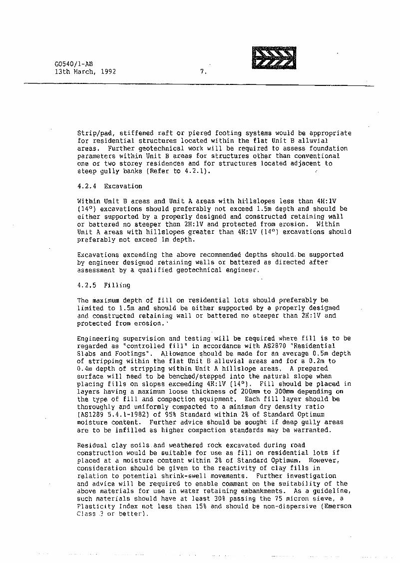
G0540/l-AE13th I'larch,1992 7, IBl
Strip/pad, stiffened raft or piered footing systems would be appropriatefor residential structures located within the flat Unit 8 alluvialareas, Further geotechnical work will be required to assess foundationparameters within Unit B areas for structures other than conventionalone or two storey residences and for structures located adjacent tosteep gully banks (Refer to 4.2.1).4.2.4 ExcavationWithin Unit 8 areas and Unit A areas with h~llslopes less than 4H:IV(14°) excavations should preferably not exceed 1.5m depth and should beeither supported by a properly designed and constructed retaining wallor battered no steeper than 2H:IV and protected from erosion, WithinUnit A areas with hillslopes greater than 4H:lV (14°) excavations shouldpreferably not exceed 1m depth.Excavations exceeding the above recommended depths should. be supportedby engineer designed retaining walls or battered as directed afterassessment by a qualified geotechnical engineer.4.2.5 FillingThe maximum depth of filIon residential lots should preferably belimited to 1.5m and should be either supported by a properly designedand constructed retaining wall or battered no steeper than 2H:IV andprotected from erosion ..Engineering supervision and testing will be required where fill is to beregarded as ~controlled filln in accordance with AS2B7Q "ResidentialSlabs and Footings". Allowance should be made for an average 0.5m depthof stripping within the' flat Unit B alluvial areas and for a O.2m toO.4m depth of stripping within Unit A hillslope areas. A preparedsurface will need to be benched/stepped into the natural slope whenplacing fills on slopes exceeding 4H:IV (14°). Fill should be placed inlayers having a maximum loose thickness of 200mm to 300mm depending onthe type of fill and compaction equipment. Each fill layer should bethoroughly and uniformly compacted to a minimum dry density ratio(AS1289 5.4.1-1982) of 95% Standard within 2% of Standard Optimummoisture content. Further advice should be sought if deep gully areasare to be infilled as higher compaction standards may be warranted.Residual clay soils and weathered rock excavated during roadconstruction would be suitable for use as fill on residential lots ifplaced at a moisture content within 2% of Standard Optimum. However,consideration should be given to the reactivity of clay fills inrelation to potential shrink-swell movements. Further investigationand advice will be required to enable comment on the suitability of theabove materials Eor use in water retaining embankments. As a guideline,such materials should have at least 30% passing the 75 micron sieve, aPlasticity Index not less than 15% and should be non-dispersive (EmersonC!ass3 or better).
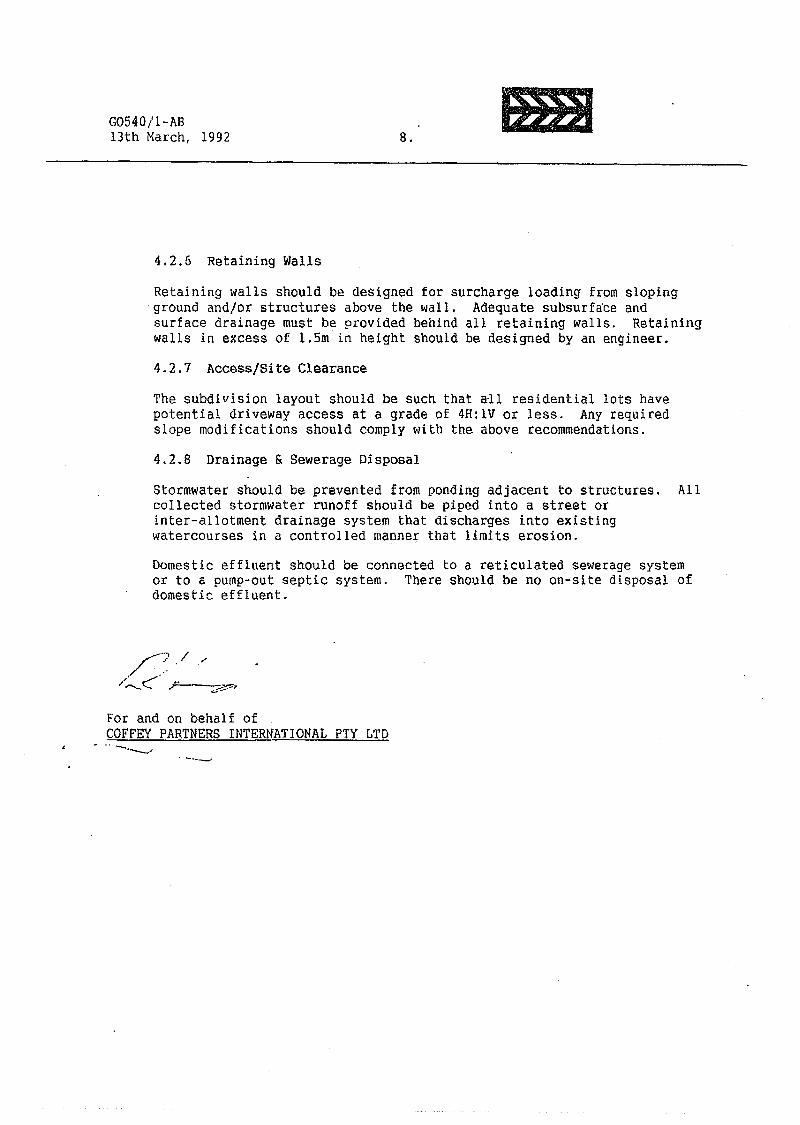
G0540/1-AB13th March, 1992 8.
liB
4.2.6 Retaining WallsRetaining walls should be designed for surcharge loading from slopingground and/or structures above the wall. Adequate subsurface andsurface drainage must be provided behind all retaining walls. Retainingwalls in excess of 1.5m in height should be designed by an engineer.4.2.7 Access/Site ClearanceThe subdivision layout should be such that all residential lots havepotential driveway access at a grade of 4H:IV or less. Any requiredslope modifications should comply with the above recommendations.4.2.8 Drainage & Sewerage DisposalStormwater should be prevented from ponding adjacent to structures. Allcollected stormwater runoff should be piped into a street orinter-allotment drainage system that discharges into existingwatercourses in a controlled manner that limits erosion.Domestic effluent should be connected to a reticulated sewerage systemor to a pump-out septic system. There should be no on-site disposal ofdomestic effluent.
~7./ .'
/"~C··· ,"''',---~.,
For and on behalf ofCOFFEY PARTNERS INTERNATIONAL pry LTD
- .. --.--....
. -~---'
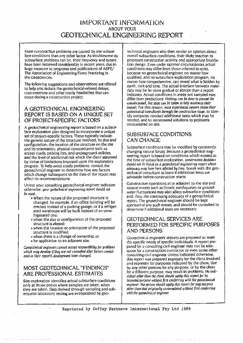
l1Y1PORTANT lNFORIVlAIfONABOUT YOUR
GEOTECHNICAL ENGINEERING REPORT
More construction problems are caused by site subsur~face conditions than any other factor. As troublesome assubsurface problems can be. their frequency and extenthave been lessened considerably in recent years. due inlarge measure to programs and publications of ASFE/The Association of Engineering Firms Practicing inthe Geosciences.
The following suggestions and observations are offeredto help you reduce the geotechnical-related delays.cost-overruns and other costly headaches that canoccur during a construction project.
A GEOTECHNICAL ENGINEERINGREPORT IS BASED ON A UNIQUE SETOF PROJECT~SPECIFIC FACTORSA geotechnical engineering report is based on a subsur-face exploration plan designed to incorporate a uniqueset of project-specific factors. These typically include:the general nature of the structure involved. its size andconfiguration: the location of the structure on the siteand its orientation: physical concomitants such asaccess roads. parking lots. and underground utilities.and the level of additional risk which the diem assumedby virtue of limitations imposed upon the exploratoryprogram, To help avoid costly problems. consult thegeotechnical engineer to determine how any factorswhich change subsequent to the date of the report mayaffect its recommendations.
Unless your consulting geotechnical engineer indicatesotherwise, your geotedll11cal el1gineerilllJ report should notbe used:
• When the nature of the proposed structu're ischanged, for example. if an office building will beerected instead of a parking garage. or if a refriger-ated warehouse will be built instead of an ume-frigerated one:
• when the size or configuration of the proposedstructure IS altered;
• when the location or orientation of the proposedstructure is modified:
• when there is a change of ownership. or• for application to an adjacent site.
Geotechnical engineers cannot accept responsibility for proViemswhich may develop if they are ~Iotconsulted after factors consid-ered in tneir report's development have cflanged.
technical engineers who then render an opinion aboutoverall subsurface conditions. their likely reaction toproposed construction activity, and appropriate founda-tion design. Even under optimal circumstances actualconditions may differ from those inferred to exist.because no geotechnical engineer. no matter howqualified. and no subsurface exploration program. nomatter how comprehensive. can reveal what is hidden byearth. rock and time. The actual interface between mate-rials may be far more gradual or abrupt than a reportindicates. Actual conditions in areas not sampled maydiffer from predictions. Nothing can be done to prevent tflellmmlicipated. bllt steps can be taken 10 flelp minimize tfteirimpact. For this reason. most experietlCed owners retain theirgeoteclillit'al Clll1sultemts lIirQllg{1 tfle cotlstruction stage. to iden-tify varii;mces. conduct additional tests which may beneeded. and to recommend solutions to problemsencountered on site.
SUBSURFACE CONDITIONSCAN CHANGESubsurface conditions may be modified by constantly-changing natural forces. Because a geotechnical engi-neering report IS based on conditions which existed atthe time of subsurface e:<ploration, construction decisionsSllOllld not (ic 8'IS~d on a geotechnical engineering reportwliosetldequaq/llH1tl h,wl' !;ern affected {J~ time. Speak with the geo-technical consultant to learn if additional tests areadvisable before construction starts.
Construction operations at or adjacent to the site andnatural events such as floods, earthquakes or ground-water fluctuations may also affect subsurface conditionsand. thus. the continuing adequacy of a geotechnicalreport. The geotechnical engineer should be keptapprised of any such events. and should be consulted todetermine if additional tests are necessar~~
GEOTECHNICAL SERVICES AREPERFORMED FOR SPECIFIC PURPOSESAND PERSONSGeotechnic.:l! engineers' reports are prepared to meetthe specific needs of specific individuals. A report pre-pared for::'1.:onsulting civil engineer may not be ade-qUJte for J construction contractor. or even some otherconsulting civil engineer. Unless indicated otherwise.this report was prepared expressly for the client involvedand expressly for purposes indicated by the client. Useby any other persons for any purpose. or by the clientfor a different purpose. may result in problems. No il1di-vidual other tli,m the client should appl!I tflis report for itsintended purpose withollt firs! conferring witf, tfle geotechnicalengineer. No person sliould apply lftis report for any purposeother tlian titat originally cOHtemplated without first conferringwith the gl!{)/eclinic'll engi~leer:
MOST GEOTECHNICAL "FINDINGS"ARE PROFESSIONAL ESTIMATESSite exploration identifies actual subsurface conditionsonly at those points where samples are taken. whenthey are taken. Data derived through sampling and sub-sequent laboratory testing are extrapolated by geo-
Reprinted by Coffey Partners International Pty Ltd 1989
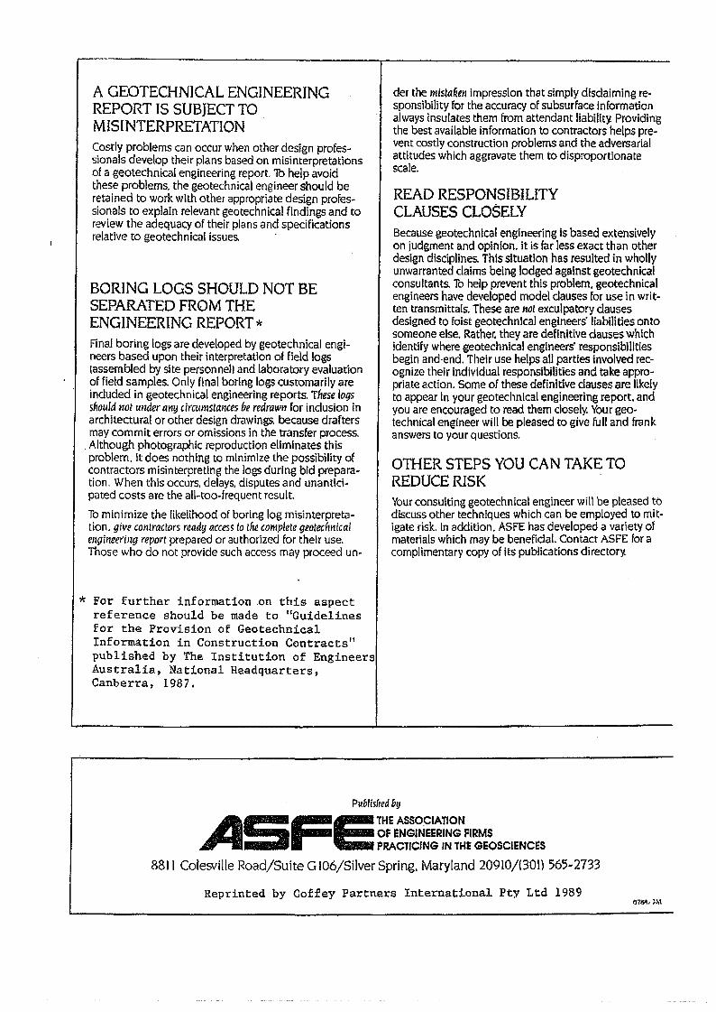
A GEOTECHNICAL ENGINEERINGREPORT IS SUBJECT TOMISINTERPRETATIONCostly problems can occur when other design profes~sionals develop their plans based on misinterpretationsof a geotechnical engineering report. To help avoidthese problems. the geotechnical engineer should beretained to work with other appropriate design profes-sionals to explain relevant geotechnical findings and toreview the adequacy of their plans and specificationsrelative to geotechnical issues. -
BORING LOGS SHOULD NOT BESEPARATED FROM THEENGINEERING REPORT *Final boring logs are developed by geotechnical engi-neers based upon their interpretation of field logslassembled by site personnel) and laboratory evaluationof field samples. Only final boring logs customarily areincluded in geotechnical engineering reports. These logsshould not under allY circumstances be redrawn for incluSion inarchitectural or other design drawings. because draftersmay commit errors or omissions in the transfer process.
. Although photographic reproduction eliminates thisproblem. it does nothing to minimize the possibility ofcontractors misinterpreting the logs during bid prepara-tion. When this occurs, delays. disputes and unantici-pated costs are the all-too-frequent result.
To minimize the likelihood of boring log misinterpreta-tion. give contractors ready access to the complete geotechnicalengineering report prepared or authorized for their use.Those who do not provide such access may proceed un-
der the mista~en impression that simply disclaiming re-sponsibility for the accuracy of subsurface informationalways insulates them from attendant liability. Providingthe best available information to contractors helps pre-vent costly construction problems and the adversarialattitudes which aggravate them to disproportionatescale.
READ RESPONSIBILITYCLAUSES CLOSELYBecause geotechnical engineering is based extensivelyon judgment and opinion. it is far less exact than otherdesign disciplines. This situation has resulted in whollyunwarranted claims being lodged against geotechnicalconsultants. To help prevent this problem. geotechnicalengineers have developed model clauses for use in writ-ten transmittals. These are t10t exculpatory clausesdesigned to foist geotechnical engineers' liabilities ontosomeone else. Rather. they are definitive clauses whichidentify where geotechnical engineers' responsibilitiesbegin and-end. Their use helps all parties involved rec-ognize their individual responsibilities and take appro~priate action. Some of these definitive dauses are likelyto appear in your geotechnical engineering report, andyou are encouraged to read them closely. Your geo~technical engineer will be pleased to give full and frankanswers to your questions .
OTHER STEPS YOU CAN TAKE TOREDUCE RISKYour consulting geotechnical engineer will be pleased todiscuss other techniques which can be employed to mit-igate risk. In addition. ASFE has developed a variety ofmaterials which may be beneficial. Contact ASFE for acomplimentary copy of its publications directory.
* For further information on this aspectreference should be made to f1Guidelinesfor the Provision of GeotechnicalInformation in Construction Contractslf
published by The Institution of EngineersAustralia. National Headquarters,Canberra. 1987.
Publisfred fl!J
ASFETHEASSOC'AT'ONOF ENGINEERING FIRMSPRACTICING IN THE GEOSCIENCeS
8811 Colesville Road/SUite G I06/Silver Spring. Maryland 20910/(301) 565-2733
Reprinted by Coffey Partners International Pty Ltd 1989011\l1. ~M
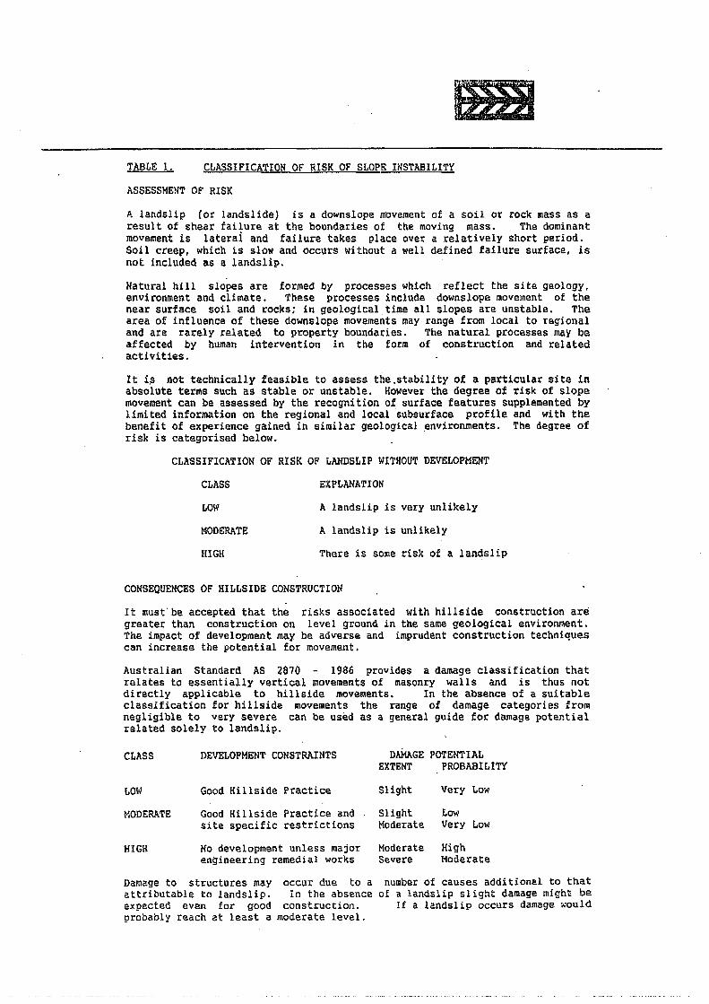
TABLE 1. CLASSIFICATION OF RISK OF SLOPE INSTABILITYASSESSMENT Of RISKA landslip (or landslide) is a downslope movement of a soil or rock mass as aresult of shear failure at the boundaries of the moving mass. The dominantmovement is laterai and failure takes place over a relatively short period.Soil creep, which is slow and occurs without a well defined failure surface, isnot included as a landslip.Natural hill slopes are formed by processes which reflect the site geology,environment and climate. These processes include downslope movement of thenear surface soil and rocks; in geological time all slopes are unstable. Thearea of influence of these downslope movements may range from local to regionaland are rarely related to property boundaries. The natural·processes may beaffected by human intervention in the form of construction and relatedactiVities.It i~ not technically feasible to assess the.stability of a particular site inabsolute terms such as stable or unstable. However the degree of risk of slopemovement can be assessed by the recognition of surface features supplemented bylimited information on the regional and local subsurface profile and with thebenefit of experience gained in similar geological ~nvironments. The degree ofrisk is categorised below.
CLASSIFICATION OF RISK OF ~ANDSLIP WITHOUT DEVELOPMENTCLASS EXPLANATIONLOW A landslip is very unlikelyMODE:RATE A landslip is unlikelyHIGH There is some risk of a landslip
CONSEQUENCES OF HILLSIDE CONSTRUCTIONIt must'be accepted that the risks associated with hillside construction aregreater than construction on level ground in the same geological environment.The impact of development may be adverse and imprudent construction techniquescan increase the potential for movement.Australian Standard AS 2870 - 1986 provides a damage classification thatrelates to essentially vertical movements of masonry walls and is thus notdirectly applicable to hillside movements. In the absence of a suitableclassification for hillside movements the range of damage categories fromnegligible to very severe can be used as a general guide for damage potentialrelated solely to landslip.
CLASS DEVELOPMENT CONSTRAINTS DAMAGE POTENTIALEXTENT PROBABI [,ITY
LOW Good Hillside Practice Slight Very LowMODERATE Good Hillside Practice and Slight Low
site specific restrictions Moderate Very LowHIGH No development unless major Moderate High
engineering remedial works Severe ModerateDamage to structures may occur due to aattributable to landslip. In the absenceexpected even for good construction.probably reach at least a moderate level.
number of causes additional to thatof a landslip slight damage might be
If a landslip occurs damage ~ould
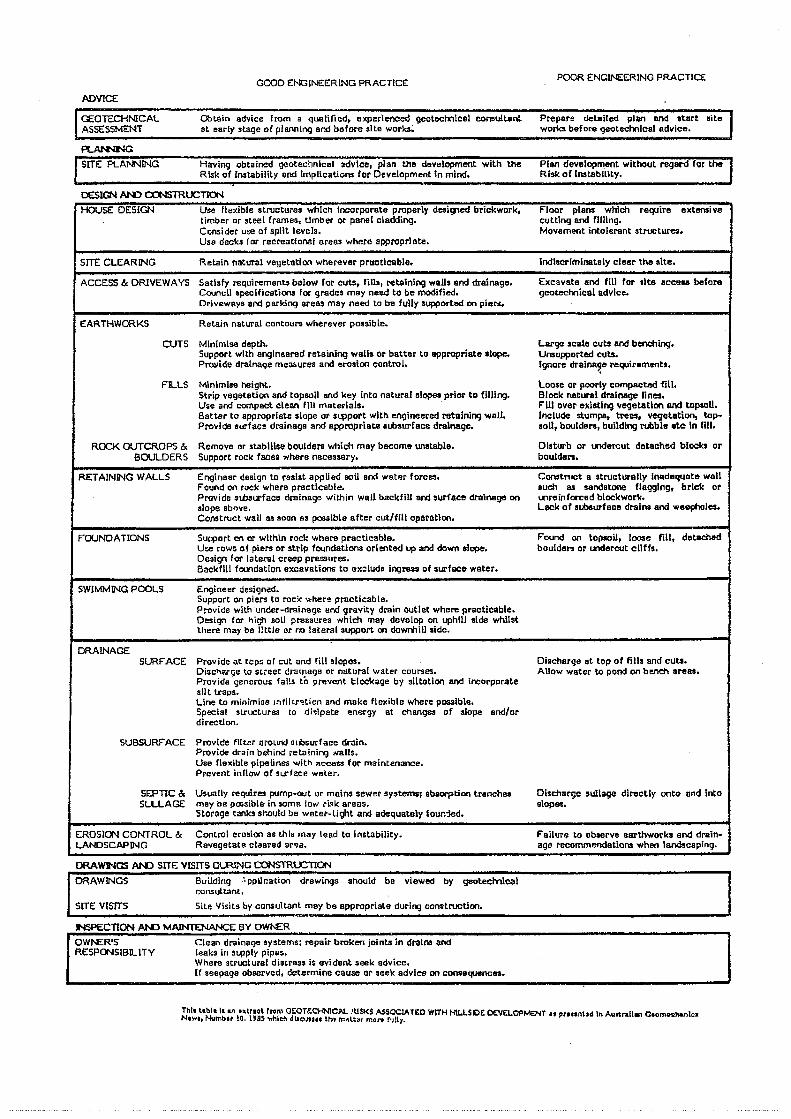
acOD ENGINEERING PRACTICE POOR ENGINEERING PRACTICE
ADVICE
GEOTECHNICALASSESSMENT
Obtain advice from a qoolifted, experienced geotechnicel COl'llIult8ntal early stage 0( pJ8lll1ing and bafore site works;
Prepare detailed plan end ttart siteworks befDre qeotechnlC41 advice.
~SITE PLANNING Having obtained geoteetmical advice, plan the development with the
Risk of Instability ond ImplicatiDns for Development In mind.PIBIl development without l"ei.j8Mffor theRisk of Inst8bility.
DESIGN f>JoD a:l'lSTRUCTIONHOUSE DESIGN Use flexible structures which incorporate properly desil11ed brickwork, Floor pions which require extensive
timber Dr sleel frames, timber or panel cladding. cutting and filling.Coosider use of split levels. Movement intolerant structures.Uso decks for recrantional areas where appropriate.
SITE CLEARING Retain natural vegetation wherever procdcllble. Indiscriminately clear the site.
ACCESS & DRIVEWAYS Satisfy requirements balow for cuts, fills, retaining waDs and drainage. Excavate and fill for tlte accasa beforeCouncil specifications for grades may need to be modified. geotechnical advice.Driveways and parking areas may need to be fully supported on pieN.
EARTHWORKS Retain natural contours wherever possible.
OJTS Minimlse depth. Large scale cuts and benching.Support with engineered retaining walls or batter to appropriate slope. Unsupported cuts.PI'Q\/ide drainage mea!>ures and erosion control. 19"ore drainage requirements.'.
FILLS Mlnimise height. Loose or poorly CDmpacted fill.Strip vegetatiQl'\ and topsoil and key into natural slop-es prior to filling. Blocle natural drainage lines.Use and compact clean fill materials. F'ill over existing vl!getatlon end topsoU.Batter to appropriate slope or SL1=!portwith engineered retaining walL Include stumps, tre~. ve<jetatioo, top-Provide surface drainaga and appropriate aLbsurface drainage. soil, bouldars, building rubble ate In fill.
ROCK OUTCROPS & Remove or stabllise boulders which trloy become unstable. Disturb or Ulderout detached blocks orBOULDERS Support rock faces where necessary. boulders.
RETAINING WALLS Engineer design to resist appUed !lOU and water forces. Construct a structutally Inadequate wallFound on rDck where practicable. such as sandatOlle flawing, brick orProvide .nbsurface drainage within wall backfill and surface drainage on Ulreinforcad blockworle.slope abnve, Lack of subsurface drains and weepl'lJles.Construct wall as soon 8S poaslble after cut/fill operation.
FOUNDATIONS SuppDrt en or within rock where practicable. Found on lopsoil, loose fill, detacll&dUse rows of piers or strip fo',mdatlons oriented up and down slope. boulders or undel'ClJt cliffs.Design for lateral creep pressures.Backfill foundation excavations to exclude ingress of surfooe water.
SWIMMING POOLS Engineer designed.SuppDrt on piers to roc'< where prncticable.Provide with under-drainage and gravity drain outlet where practicable.Design for l1ig, soil pressures which may develop on uphill ~ide whilstthere may be IJttle ar no lateral support on dowmllliide.
DRAINAGESURFACE Provide at tops of cul and nil slopos. Discharge at top of tills and cuts.
Disc"arge to SLreeC drainage or natural water CDUrses. Allow water to pond on bench areas.Pro'lide generous falls to prevent l;;IOCkage by siltation and incorporatesilt lraps.Line tD minimina Inti! [J'~tion and meke flexible where possible.Special structures to d;"ipate en<.:rgy at changes of $lope end/ordirection.
SUBSURFACE Provide filter al'ollnd subsurface droln.Provide drain behind retaining Nalls.Use flexible pipelines with "ceeSS for maintenance.Prevent inflOW of surface water.
SEPTIC & Usually requires pump-out ur mains sewer systerns; abaorption trenches Discharge sullage dll'8ctly ooto and intoSLLLAGE may be !>CIIsibleIn some low riSk areas. slopes.
Storage tanks sl'.ould be water-light and adequately foun1ed.
EROSION CONTROL & Control erDsloo as this may lead to instability. Failure to observe aarthworks and drain-LANDSCAPING Revegetate clllQred ar~a. age recommendations when landscaping.
ORAWJ04GS AN) SITE VISITS QLR.,"'lG CONSTROCTIONDRAWINGS Building ,'·ppUr.ation drawings should be viewed by geDleclYllcal
consultant.SITe: VISITS Sill' Visits by COOS'Jltanl may be appropriate during cOOlllructicn.
NSPECTION AN) MAINTENANCE BY OWNEROWI'£R'S Clean drainage systems: repair broken joints In drains andRESPONSIBU-ITY leaks ill s~ply pipes.
Where structural disLress is evidant seek advice.If seepage observed, determine cause or seek advice on consequences.
Thl. llbll '" on •• traol r",n' m::on:C'H'-lICJIl. ~1lSl<$ASSOClATED WITHHIl.LSIOE OEVELOPMENT .. pr... Mld In AIJltrall .. ClOmo=hanl""N.,.", Numb .. la,IUS ...nloh dll"" .... 1M "'.l;" mort MI,.
-..... en o --It
--It _. CD - Co _. ~
~
CD"
!!l.m
cO·
z-Q)
C....
-0·
><:J
»
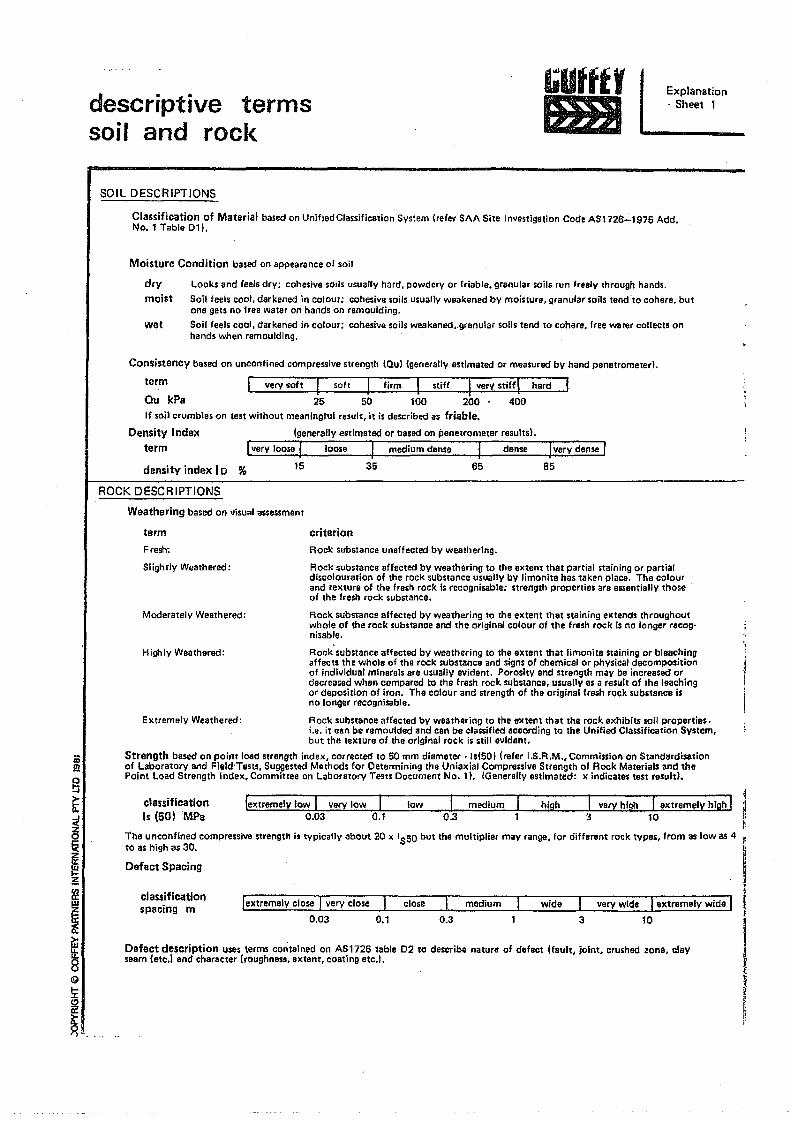
iil!!g"'"t
I~
i~@
!i:
~~"
descriptive termssoil and rock
IiUfffYtm1
Explanation. Sheet 1
SOIL DESCRIPTIONS
Classification of Material based on Unjfied Classification System (refer SAA Site Investlgation Code ASl726-1975 Add.No.1 Table 011.
Moisture Condition based on appearance 01 soil
dry
moistLOoks and feels dry; cohesive soils usually hard. powdery or friable. granular soils run freely through hands,Soil feels cool, darkened in colour; cohesive soils usually weakened by moisture, granular soils tend"to cohere. butone gets no free water on hands on remoulding.Soil feels cool. darkened in colour; cohesive soils weakened.,granular soils tend to cohere. free waler collects onhands when remoulding.
wet
Consistency based on unconfined compressive strength tQullgenerally estimated or measured bV hand penetrometer}.
term I very soft I soft I firm I stiff I very stiffl hard IQu kPa 25 50 100 200· 400If soil crumbles on test without meaningful result, it is described as friable.
Density Index (generally estimated or based on penetrometer results).
term Ivery loose I loase I medium dense I dense
3515 65 85density index I0 %
ROCK DESCRIPTIONS
Weathering based on visual assessment
criterion
Rock Substance unaffected by weathering.
Rock substance affected by weathering to the extent that partial staining or partialdiscolouration of the rock subSfsnce usually by limonite has taken place. The colourand texture of the fresh rock Is recognisable; strength properties are essentially thoseof the fresh rock substance.
Rock substance affected by weathering to the extent that staining eKtends throughoutwhole of the rock substance and the original colour of the fresh rock Is no longer recog-nisable.
Highly Weathered: Rock substance affected by weathering to the extent that limonite staining or bleachingaffects th e whole of the rock substance and signs of chemical or physical decompositionof individual minerals are usually evident. Porosity and strength may be increased ordecreased when compared to the fresh rock substance, usually as a result of the leachingor deposition of iran. The colour and strength of the original fresh rock substance isna longer recognisable.
Extremely Weathered: Rock substance affected by weathering to the extent that the rock exhibits soil properties.i.e. it can be remoulded and can be classified according to the Unified Classification System,but the texture of the original rock is still evident.
Strength based on point load strength index, corrected to 50 mm diamater ·ls1501 (refer I.S.R.M .• Commission on Standardisationof Laboratory and Field'Tests. Suggested Methods for Determining the Uniaxial Compressive Strength al Rock Materials ami thePoint Load Strength Index. Committee on Laboratory Tests Document No.1). (Generally estimated: x indicat&s test resultl.
term
Fresh:
Slightly Weathered:
Moderately Weathered:
classificationIs (50) 'MPa
The unconfined compressive strength is typically about 20 x IS50 but the multiplier may range, for different rock types, from as low as 4 ;ta as high as 30. I
I
I:
I~~I.~I~I'
Defect Spacing
clauificationspacing m extremely wide
0.03 0.1 0.3 3 to
Defect description uses terms co~tained on AS1726 table 02 to describe nature of defect Hault, joint, crushed zone, clayseam letc.1 and character (roughness, extent, coatinG etc.].
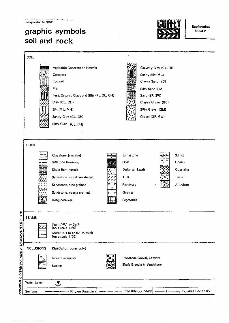
....." , . - ,._uY··_ . ~J ~Incoc-poreted in NSW
graphic sy~bolssoil and rock
CUfflYImJI
Explanation. Sheet 2
SOil
Asphaltic Concrete or Hotmlx Gravelly Clay (Cl. CHI
Sandy Silt (Ml)
Clayey Sand (SC)
SiltY Sand (SM)
Sand (SP. SW)
Clayey Gravel (GC)
Silty Grallel (GM)
Gravel (GP. GW)
Concrete
Topsoil
Fill
Peat. Organic Clays and Slits (Pt. Ol. OH)
Clay (Cl, CH)
Silt (ML, MH)
Sandy Clay (Cl, CHI
SiltY Clay (Cl. CHI
ROCK
=-= fiiClaystone (massive) Limestone 1..;:'-";..1 Schist
Siltstone (massive) Coal r-_-I Gneiss
Shale (laminated) Dolerite. Basalt ••••• Quartzite•••••Sandstone (undifferentiated) Tuff A Talus
Sandstone. fine grained Porphyry ~ [?.\~~~ Alluvium
Sandstone. coarse grained "Granite
Conglomerate Pegmatite
~I SEAMS§~
~
~Il------------------------------ffiil INCLUSIONS
~
Seam >0.1 m thick(on a scale 1 :501Seam 0.01 m to 0.1 m thick(on a scale 1 :50)
(Special purposes only)
l2
1/ ~8iI W''''''.,v,1 _ I~ I
~I Surfaces
Rock Fragments
~
~:t·t.
. "00:'
Ironstone Gravel, laterite
Shale Breccia in SandstoneSwamp
..Y..
Known BoundarYI -- -- - Probable Boundary I --? _? Possible Boundary
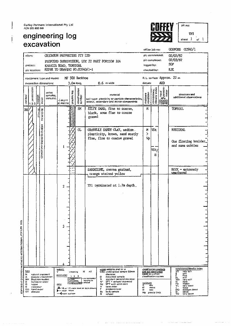
Coffey Partners International Pty ltdACN 003 692 019
engineering logexcavation
COffEY r
IHBJoffice job no:
pit no:
TI'1
I sheet 1 of 1
GOSFaID G0540/1client: CRIGHION PROPERTIES PlY L1D
PROPOSEDSlP.3DIVISION, wr 22 PART f'CRTION 104project: K'\RftLTA ROAD, TI.RRIGALpit location: REFm ID rnAm:N; ID.G0540/1-1
NF 500 Backhoe3.Omlong.
equipment :vpe and model:
excavation dimensions: 0.6 mwide
c: ".g'" .g
'" notes g .,"~ I ~ w'" materialsamples.
~u_ :i.g
c ~ 0 ;::0
~ ~ a :! tests.etc. -!dep: .. '~e soil type: plasticitY or particle characteristics. ~~~,., ~ S> colour. secondary and minor componeRlse 123 a ~ a: metr-::s '" u~ ea
pit commenced:
pit completed:
logged by:
checked by:
02/03/9202/03192SGFRJK
1'1
6::;L-0 .. .,cc:-~~ekPa
00000000-NMq"
R.t.. surface: Approx. 22 m
datum: AHDx..,
>'0Uc:C:._
.~.~c:c0"u-o
--VSt/,
H
SANDSTONE,coarse grained,orange stained yellO\~
chsuification symbolsand soil descriptionbBsed on unifiedchaslrir:atlon. 'Sy.srem
trIoisltU'l!o--urvM mOist'tV wetWp plaslic limit
structure andadditional observatiDns I
ISM TOPSOIL 1
=!I
11
.SILT'i SAND,fine to coarse,black, SOl:Ie fitle to coarsegravelnN
II 0NE
~
l~-J)12v;, oj:'
CL GRAVELLY SANDY CLAY, medium.plasticity, brOloJrl, sand mostlyfine, fine to coarse gravel
~
~~
I I 4
TPI terminated at 1.7mdepth.2 -I
~-
~~...
3 -
-
-
~ samples and Ie' toU50 undisturbed sample 50mm
diametero disturbed sampl.N 'Standard penetratIon tests:N' 5PT + sample teCOyereclNc SPT with solicl coneV vane shearP pr t! So$tlre met erBs bulk sampl.R relusal
SUPIJCr1T-- :,mDering N nil
/oJXBHe
clRc:).
'"8
pilnl!uaticn \ 2 3
~~not?;'I.nc.
r'!I'g~ng torefusal
EI-iAoT
..:. 10 :~R ;-5 \'fattle le""el on Ooliteshown~ ....ofI:~ ,f1aw~~.·a:!!t Out!IOw
RESIWAL jI
One floating boulder-Jand somecobbles --!
1!
1-;""1l
RC<K - extreme.lylveathered
consistency/density indexVS yery sailS saf,f firm51 stiflVS, ycrVltUrH hardFb f,iableVL very loo~eL 100$6MD medium t1ensto clensoVD very dense
-
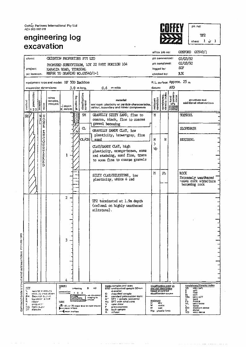
Coff:Y Partners Inlernational Ply LId'>'CN 003 692019
engineering logexcavation
COffEYIDB
oftiC!! job no'
pit no:
TI?2sheet 1 01 1
GOSFaID G0540/1
c1i~llt: CRIGHION PROPERTIES PI"l LID
PROPOSED SUBDIVISION, wr 22 PART ECRTION 104project: KARALTA ROAD, nmUGAL;>itlocatlon: REFER TO mAtiiN3 ID.G0540/1-1
pit commenced: 02/03/92pit completed: 02/03/92logged by: SGFchecked by: RJK
~l<cavation dimensions:
equipment wpe and model: l'lF 50D Backhoe
3.0 mlong. 0.6 mwide
.g :;, -3:: notss g .. OJe;,:; samples, .g u_ material :i.gc a :ests,etc. ~Q
sOli tYpe: plasticity or particle characteristics. .~~OJ "" -! depth 'E. ~~c. ~ ~ e .. - colour. secondary <lnd minor components- ,1 2 3 ~ -> eaa:: mettes '" u'"
datum:
R.L. surface: Approx. 25 m
"'OJ>'tl0c:c:._!>.. -ow; ow;c:=0"0"0
AHDe
~;:;~g~,;
.:: Q. EkPa
0000coco-NMv
structure andadditional observations
-..-
4 -I I
Ii.IJUJJor~
T tlmbe,ir:g N nil
IN10IN
I ~, cI 0I IUI NI I ~Ii I~
lID
, III,. !
'"~
&~r:-3·.a~::-·
flT iI . I
I I I
[' I I IIII I
r__ ::!Y"
61'~ XG :Ht: i"
'"
naIV~a! o! ... :HH,,;r-:ex.s:.~~; ~~<t::.! ..atlQr~Bae:., ":0;0 ~u "~,,,'~Hbu:;(:o::.;r· ;) :::ertr)IN·
F I HA hi)I"C: .iI...=":'~:3 0T dialt ..b~u
GRAVELLY SILTY SAND, fine tocoarse, black, fine to coarse
r.'+-'t---h gravel becomitJg
GRAVELLY SANDY CLAY, lowtT"I---;, plasticity, brown-grey, fine
sand 1MCLAY/SANDY CLAY, high ~plasticity, orange-brown, sorne P
1 red staining, sand fine, traceto some fi.ne to coarse gravels
!Hil SM
1P2 tei:mf.nated at 1.9m depth(refusal on highly weatheredsiltstone).
N
r
M Fb
:....-
H
classification symto alsand SOil dM'cl'lptlonbilted on uniiiedclasslfJc31iof\ synem
mojS1:1JUD dryM moiscW wet
Wp plastic fimit
1OPSOIL -
SlOPElo1ASH il
SILTY CLAY/SILTh'TONE, 1~'1plasticity, lmite & red
2 -j-<
~
13 -
!!2W somples and testsUSO undi~lurbed ~ample50m",
dHlme1ero dlSlurbed sempleN 5tandard penetration tests:1'1 • SPT + <amplerecoveredNc SPTwilh ~olrd coneV vane ~hearP pressurernelerB~ bul%sampleR refus~1
RfSIOOAL
.,
~
1
pen81,.afIDn 1 '2 3
~
_nor~'1"13nc:etiJl1gmg 10c;.e:=="",,,,,,, tefusel~
..=r"'~10 ~!~ 18 ~al~t Jeli~1 ~ mue shown~Vlalt" ir(I:JII"1
~v/~te:' .:>vtfiOW
:JRcx:K IExtremely weathered I-some rock strue ture -becoming rock -
-j
jJ
COJ1sj"luncvldon1:ity indsxVS very softS softF firmSf stiffVS, very nillH hardFb friableVL very loo,eL looseMD mp.dium den'Sto denseVO very dense
-
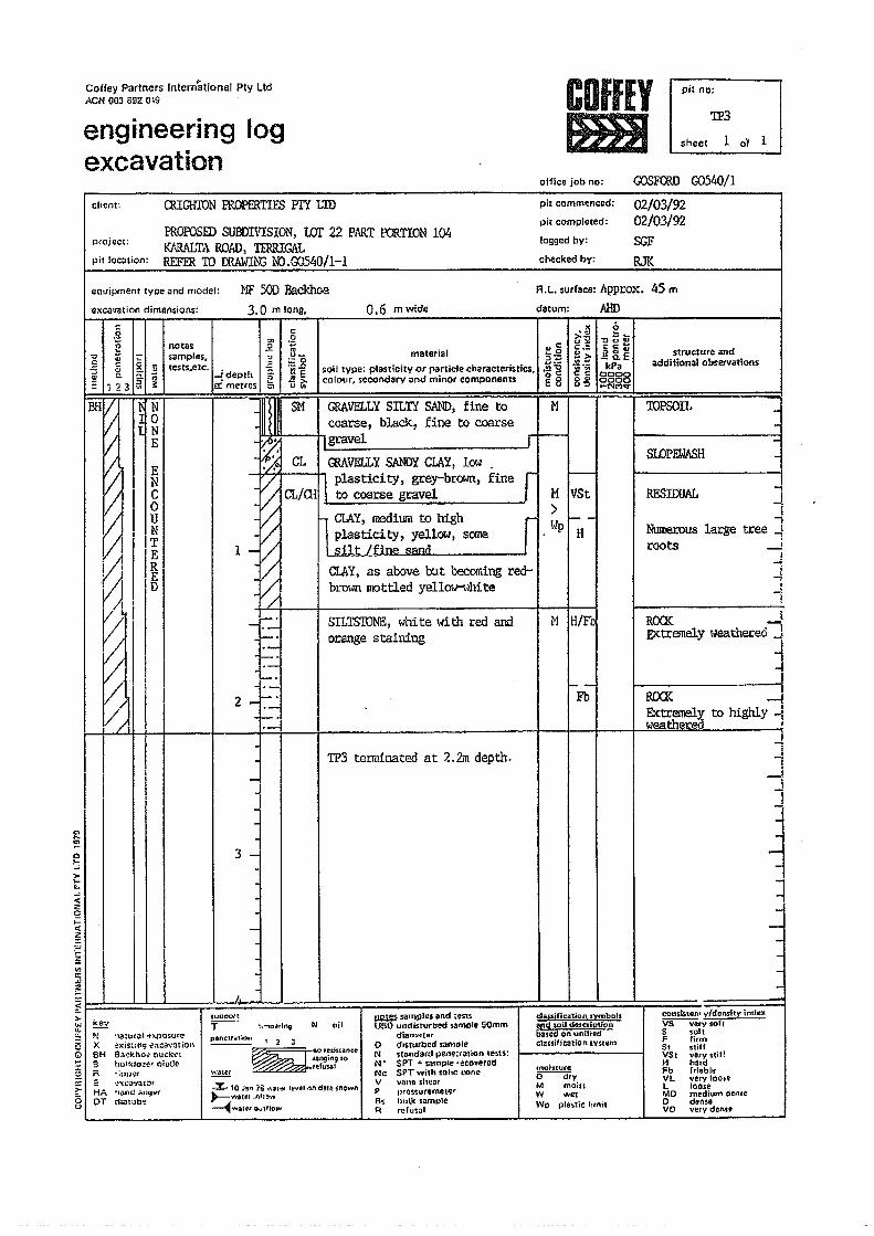
Coffey Partners Inlern'aUonal Ply LIdACN 003 692 019
engineering logexcavation
COfflYmJ
office job no:
pit no:
TI3
sheet 1 o'f 1
client:
OJSFaID 00540/1
QQGlITON FROPERTIES PlY LID
PROPOSED SUBDIVISIOL~. wr 22 PilRTEl:JRTION 104KlIRALTA ROAD l 1'ffiRIGALREFER TO CRAl.JIN3 1>0.00540/1-1
project:
pit location:
pit commenced:
pit completed:
logged by:
checked by:
02/03/9202/03/92SGFRJK
eQ"ipment type and model:
excavation dimensions:
MF 500 Backhoe3.0 m long,
c c.2'" .g~I~, notes E Itl IIlc
samples.~
u_ material :Jag:=0 ....-.z Ci Q ;; tests,etc. -!depth..~ -g soil type: plasticity or particle ch.aracteristics. .i;]
-;;: Co ;:;- n ;; 3- colour, secondary and minor components E B~ 123 a ;: n:. metres ~ u~
l<.'">'::)<J~c.:
.~.~<: :::0<>... on
0.6 m wide datum:
R.L. surface: Appro>::. 4S m
~j
AHDot:~
'::I III III:::C:Qi~l!iEkPa
gggg-('\,IM1;I"
structure andadditional observations
-- -_.-~-NI 0
NE
I EI NI C
I I 0-
~
ul
II I~I IEVJ i IR,V11 !E
III!
~!
i II i
I i
// I
~ SM
I.-
~ IVS~tJP~
<t2'2...<t2'"l-ii:""c::""2~b---I I I 1 I 4:~ I I I I I '1~ I • i I
f'i
-
2 f~.-1r-
I, IIII I
~3 -
-I I J.
C>"-~<:>~>-t
.
suP"or~T-->- -OJ Keyu,. -:.:..Ni3 XQ 6H~ 3~ R>-isu
~,""c'l!'IJ\l]·la:ut'aJ "f>'I)'.;suree~ist:nt: 1?:tco,\'.otiol\S:tCkhO~ ouc~~thuHdo.!~rolatlc";IJINt~"'ca·Jatm'lime aI.l9~(dz:lt;Jb~
peneUi,lItion 2 3~no.~,;".nce
s.angu'l910I fe{uS3t~
"
SILTSWNE, I,hite \.,rith red andorange staining
TP3 terminated at 2.2m depth.
~ samples and 't~StSUSO undisturbed ,ample 50mm
diamnterD dIsturbed sampleN 'itandardpenr:,ation tests:N· SPT + sarnple ·:ecoverod"Nc SPT with solie coneV vane 511110rP vres.suremel'!r'8s bulk ,ampleR refusiJl
cons:1Slen1 y/dollsity indexVS very,oh$ softF firm$, stif!VSt very stiHH hardFb friableVL very IOO~!L loo'eMD medium denseD den.eVO very denl.
N nil
4 to Jl1t\ is ....o1I'~' le,",1I1on dat~ inOlIIn"""-water ,1')'1::)"'"
~waCf" O...t~low
HADT
1'1 IH/Fb
--Fb
moistureo--dryM moistW WRt
Wp plastic I'mi,
TOPSOIL -SLOPEWASH
-...,JJ
Numerous large tree Jroots -1
RFSIOOAL
Jt-:.1
ROCK ...JEXtremely lo1eathered J
~RC(I{ .....JElCtremely to highly -fweathered'
I..-1
--!
i-
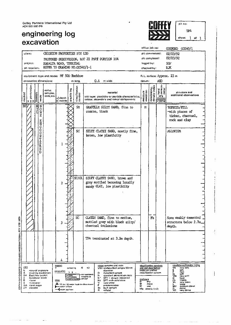
Coffey Partners International Ply LidACN 003 6;12 019
engineering logexcavation
COffEY1m)
office job no:
pit no:
TI?4
sheet 1 of' 1
OOSFCRD00540/1cHern: OOGHION PROPERTIES PrY L'IO
PRorosED SUBDIIJISIQ.~, wr 22 PART F<RTION 104proj ect: KARALTAROAD, TERRlGALpit location: R.EFER TO ffiA~ N).OOS40/1-!
R.L. surface: Approx. 23 m
AHD
pit commenced: 02/03/92pit completed: 02/03/92logged by: SGFcheeked by: RJK
equipment type and model: MF SOD Backhoeexcavation dimen,ions:
;
N10
NE
ENC0UNTERED
~
~
~II ,
~1l-.6turar !:xposureeXisting e:<cavatJo,~aackhoe buckc,,;bundol~r blDdttI!pp~r
tit:. ·\>:\ca·,i1toC'
8 aT c!iatubeH,\
'"notes I .2samples, .~testsJetc.. h':;
-! dept ~a: metres '"
-
I I 4 -
8M
1
I·::~.ISC/CL2 '. '.:.. ' .. ' .
id.::
:~:,(:}
j1.:::'SC3 ....:
:.>.·r:'x::
m long,
.gOJ
~o.~.g:::I ';;!3~
0.6 m wide
materialsoil tYpe: plasticity or particle characteristics,colour. secondary and minor components
GRAVELLYSILTY SAND, fine tocoarse, black.
SILTY CLAYEYSAND, mostly fine,brown, low plasticity
SILTY CIAYEYSAL'ID,brown andgrey rrottled beccmi.ng locallysandy GLAY, 1010/ plasticity
CLAYEYSAI.'ID,fine to medium,mottled grey with black silty/charcoal inclusions
TP4 terminated at 3.2m depth.
i;UpOOr:T-- timbering
datum:
OJ:::~.g·;i~8
N
><iS~c.:U~
"C;;';;;l: c:a.g
f--Fb
o~~.., ....cc'""' ......:a EkPa
00000000__ NM1;f
structure andadditianalobservations
moistur.~yM mO·lltW wetWp pla5tic Jim;.
1-jj
I
tOPSOIL/FILL-with pieces of
timber, charcoal,rock and clay I
I
I
o~§I r /'1 I I I IX I I~ I I I I I
~:2r::w...~..0:WZ...~l I I I I I J I~IN I I ill
8 x~ BH!; B5 R
ALLUVIUM JI
.....:
!-j
ji.....Il
...J
J~J
Scme weakly cemented JstrUcture below 2.7m_depth. -
-
~
N nil~ samples and ,e.\SU50 undisturbed sample 50rnm
diametero d"tlJrbed sampleN standard penetration tesu:>i' SPT. sample recoveredNt SPT With solid cone\j v;:me shearP preS$utemeterBs bulk sampleR 'elusal
consisttr'lcv/dansity indeKVS ve.ry'SoftS ,oliF firm5t .tiffV5t V.'v .,iIfH hardFb rriableVL yerv IOOfll:L tooseMD me:e:tium (feo.seo denseVO very dense
~12~nD'~'i'l.nc.
ranging tofefUS&l1
clas:sification symbolsand 50.1 dBscdplionbased on unifiedc1autficatiol'l system
.:.. 10 Jan 78 wattt Ine. nn d.ace shown~waarinllow
:..-.cWU'" Ou~fIO\ ....
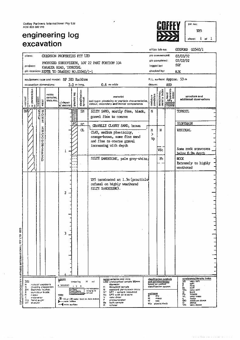
Coffey Partners International Pty LIdACN 003 692 019
engineering logexcavation
ollics job no:
COffEYtmJ
pit no:
:IPS
sheet 1 of 1
client: OUGHfON PROPERTIES PrY LID
PROPOSED SUEDlVISIOt.~, wr 22 PART FCRTION 104I:<ARALTA ROAD, TERRIGAL
pit location: REFER TO rnA\ITt'G ID.G0540!1-1
pit commenced:
pit completed:
logged by:
checked by:
project:
roSFCRD G0540/1
02/03/9202/03/92SGFRJK
equipment type and model: MF 500 Backhoeel<cavation dimensions: 3.0 m long, datum:
R.t.. surface: ApprolC. 53 m
AHD0.6 mwide
N I H>lolp
"..,>--aUe:e:_
~€c:c:0"u'"
b~~-a., ...~e:'"tacDCV.c Co E
kPaooco0000......NMV
structure andadditional observations
~
e:o';;u_
i~2>'u ..
" e:~.g.;~oC:E8
1--VSt
FbL--
TOPSOIL
SLOPEWASH
RFSIOOAL lI
-1
JSome rocl, structure i1-.. .....1...,..'1 n 0-. ...:1 .......... +-""'" -;
R<XKExtremely to highlytveathered
-
~
1J
Co!:;>-1;;:J«zo1=«zccUJI-~'"0::
'"z~I I I I I ! 4...J! I I I I I =i~ [ i i i>-'"....~ Nc.: XG 5Ht: aC P-c:>-"-cu
c:.gC1e notes .Q-I ., :: samples. .;!~ c: 0 L.. tasts,etc. .<:.5 ~ g ~ -!depln ~~= 123 a ~ a: metr~s '"
~V~,
ngE
ENCoU~ERED
matarialsoil type: plasticity Or particle characteristics,colour, ~econdar'l and minor components
SILTY SAND, mostly fine, black,gravel fine to coarse
SN ~I
CL
I 2 3
consistency/density indexVS very,olt5 softF firm5. nillVS( ....e..y SliHH ~.rdFb friableVL very looseL 100'.MO medium (H!I1Seo d...,eva very den"9
-
j'"." .
I I
..,
2 -
-
~
-3 _
-
.
~
waU:1
~"",." ... n,"ral"lgl"910r~!...s.al
~ 10 ':1'\ 18 WOller l~vell)1\ dlll~ Jhown",-'hal!t inflow~Yfil:!!r outflow
"Vl:!uoJlT-- timbering
~ADT
natt,l(:]li ~xposur~.:!:<15lin~ '!~c:Jv:Jtionaac~ho'~ hlIc~etUUI!~I~Z~r brade.. ipj,:mt~l(Cij'JiHO!"luuuj u1;.3e-:di.:Uu·r)o"! ..
p "1etuUon
.0; co,.1.GRAVELLY CLAYEY SAND, brOloJIl
ClAY, mediumplasticity,orange-brotoJIl, some fine sandand fine to coarse gravelincreasing wi th depth
r
., . I SILTI SANDSTONE,pale grey""14hi te,
TP5 terminated at 105m (practicle'refusal on highly \veatheredSILTY S{\NDSf\)~'E).
N nl'
~o dryM moistW wetWp pra'5tic: 1t00h
!.l2.1!J sampl~~ and testsUSO undisturbed lample 50m",
dlam'ltterD dislutb~cllampleN sranc:ard P'9n~~ralion H!'sU;N· SPT - sample r!!coyeredNt SPT ".I',mhsolId coni!V "lane' shil13rp pre'S5ur~mete'61 bull< •• mpl.R refusal
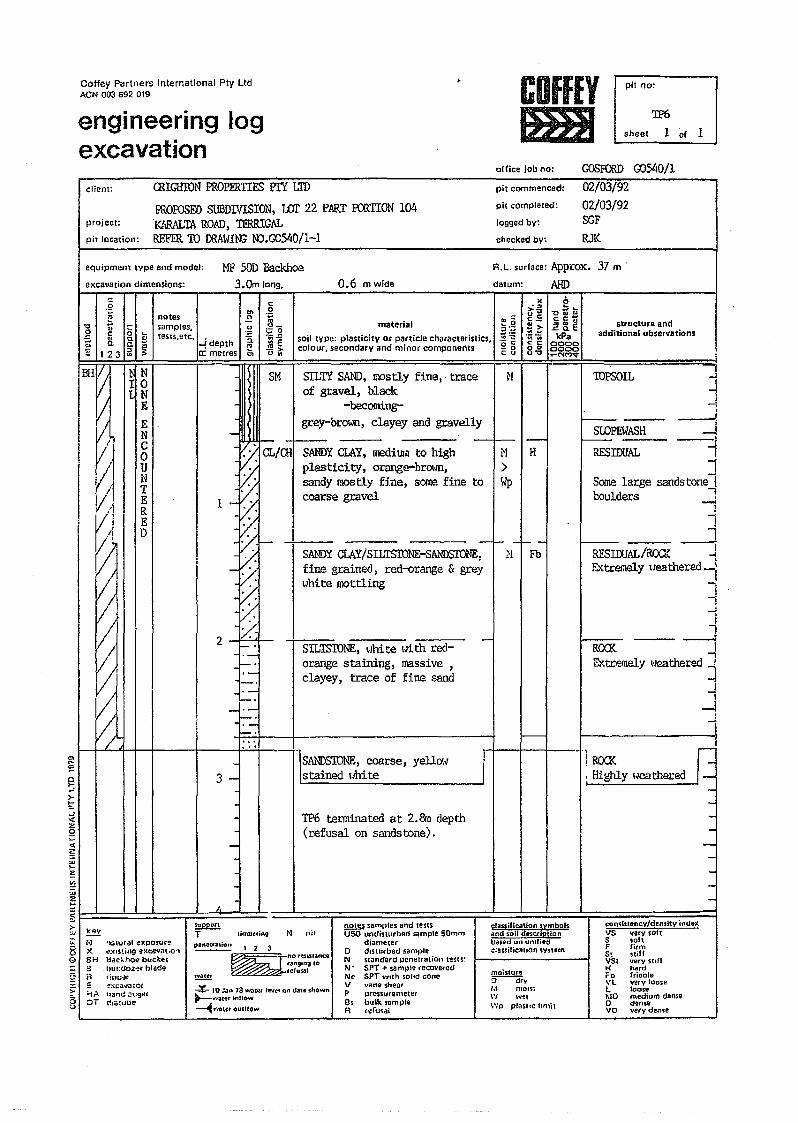
Coffey Partners International Ply LtdACN 003 692 019
engineering logexcavation
COffEYIBB
offjce job no:
pit no:
~sheet 1 ~f 1
GOSFCRD GJ:AO/lclient: OOGHION PROPERTIES PrY LTD
!:ROPOSEDSUBDIVISION, 1m 22 PART EmTION 104proj ect: KlIRALTA ROAD, TERRIGALpit location: REFER10 reAWIffi NJ.~540/1-1
pit commenced:
pit completed:
logged by:
checked by:
02/03/9202/03/92SGFRJK
equipmem type and model:
excavation dimensions:
""notes I Esamples. .!'!tests.etc. • "§.
..I depth "c: metres en
.gr;
'"0 ~ ~o .- 0 ...-5 0; ;:!- B'" 0. _ ~E 123 a
NIO
NEENC0/ U
• I NV/j iV.'l, R
I ~I ~
/I ~t
~'"...l':c~>-....""
-I I I.
MF 50D Backhoe3.Omlon9.
-HI} III SM
trIml~
~
.~. .l-
..
~
.
': ::.. /
2 "
c:.g..~o.;;; .Q.. ".!:!>.u '"
0.6 m wide
materialsoil type: plasticity at panicle characteristics.colour, secondary and minor components
R.L. surface: Approx. 37 m .
datum: AHD
1
N IH>\\fp
-t"....:t-t:-:
~33:::.~-.:o c;EB
SILTY SAND, IlPstly fine" trace I Nof gravel, black
-becomi.ng-grey-brown, clayey and gravelly
3 -
-
SANDY CLAY, medium to highplasticity, orange-brown,sandy mostly fine, some fine tocoarse gravel
$upporlT--- limDltfiAg
".">",u_c.==~"Vi-i;c:c:0"Uv
SAl.'lDYCI.AY/SILTSfONE-SA..\1J)S1DNE~ ~'llFb-'fine grained, red-orange & greyI~hite lllOttling
SIL'ISTONE, \·Ihi te \~ith red-orange staining, massive 1
clayey, trace of fine sand
"lSANDSTONE, coarse, yellOl'"stained lIhite
TP6 terminated at 2.&0 depth(refusal on sandstone).
-
I--
b-cZ!!cc:u~ ~EkPa
0=00"'00_NMq"
structure andadditional observations
J~
-----J-J-=t"1
Some large sandstone 1boulders -:-I
1I-- ---.J
RESIOOAL/ROO.< JF..xtrer.tely ueathered-l
-jI
TOPSOIL
I SLOPEWASH_RESIDUAL
11
ReCK -- ~Extremely "]eathered !
~--!
1"'1 •
! ROCK -J. Highly IJeathered _I
-
moisture5""'---;j;yM nI0'~~W woe,\~:o pf~ShC llO'lil
:;::zg«~'"~~;:;:;E~~=======r===~:'=::::: ' t • • ---=!~ key
::::: N ~.:itural e)Cposur~8: X c:crS-tinp e:<ca'li'l[,O"G 6H Backho" buc~e,
3 IJw:doz~r bladeR tillU-.l!r_I E. ~xcava tOt~ Y= tJam! :!\:gef
g :::It ~Ii;~ube
N nilconsb:llltncy/densit:y indr:x!!2.1!!1 samples and tests
USO undinurbed samp.e 50m",diameter
o dislurbed sampleN st~ndard penetration test5~N- SPT + '5a",~)Jtl'recoYel'cdNc SPT WIth solId coneV vane sheafP J]r-eS5U1QmeHH8s bulk sompleR r~ru5al
~ 123
~
no'tmilance:"ngm, co
==<""'-'== ~e1usat~-¥- 10 .:.,n 18 Wine, teve' nn dAle ~tJGwn~'i'l ... ter.rIlIOw
~"'''''tet ouClfow
classifieation symbolsiilnd so" dCtSCfiptior\.ba$~d on unllied~=aS$ificauo" sY'SUln
ySSFS,VSIHr"\.'L
klOoVO
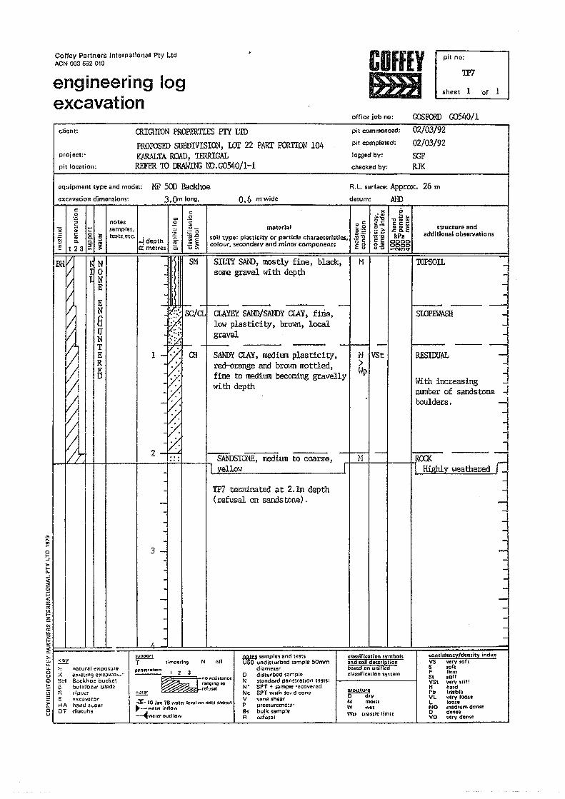
CoNey Partners International Pty LtdACN 003 692 019
engineering Jogexcavation
COffEYI&BI
office job no:
pit no;
'IF?
sheet 1 ·of
client:
GOSFORD G0540/1
project:·
pit location:
CRIGRIDN PROPERTIES PIi' I:IDmorosID SUBDI'lISION, LOr 22 PART FCR'ITON104[(ARALTA ROAD, TERRIGALREFER TO OOAWIN:;00.00540/1-1
pit commenced:
pit completed:
logged by:
checked by:
02/03/9202/03/92SGFRJK
equipment type and model: NF 500 Backhoeexcavation dimensions: 3.0n long,
I
I
.2<ii.~-_0.~ .0
~Eu~
SM
0.6 mwide
R.L. surface: Appro>::.26 m
datum: AHD
" c:a:~.~voC:E g
~l
x.'">."0<:C:._
.~.~<:<:0"0"'0
b::. .." ....cc~~~EkPa
00000000-NMqo
structure andadditional observations
<:.g'"~ notes .2'"I a; ~
samples. .::!~ :; & ~ tests.etc. £... -! depth 0-:;! Q. 0. i e::: 123 a 0: metres '"
IBH~
I 'I
ngE
EN8uNTER
l~
R~
~:.-...§I~Q ;lrl= ~g RFi5u
natural t"xposure~~\SHng ~xcavath4'"Backhoe bucketbuJldolt!t bladeriJ,)P~:'r;~C3VO~~1'hanej ~~.c~tdiatuh~ .
t-lAO.
-
~f'}SC/CLf;~1:::.:t;'
~
2-=16...-
-3 -i
-
I 1-
materialsoilwpe: plasticity or particle characteristics,colour, secondary a"d minor components
SILTY SAM)t mostly fine, black,some gravell~ith depth
-ClAYEY SAND/SANDY crAY, fine,low plasticity. brotoffi. localgravel
rnISANDYClAY, medium plasticity,red-orange and brOloffi mottled,fine to medium becoming gravellywith depth
~~ ~~~--- I ~l
N IVSt>l~p
N nilclas.sifie.ation 5vmbol.sand soil doscrlptianbased on unifiedclassificalion'S')''Stem
I
moistu/co--<r;vM mOU:1\V ~,e,WI> pt.sli~ limil
TOPSOIL "1
Jj
-ij
J
o>-.J
t~o;:::<za:"'...~....c:'"z...~I I I J I ! 'I ..' , , : ' , --,=- Iii i
-I I I.
suutJOftT--- timoerfng
TP7 terminated at 2.1m depth(refusal on sands tone) .
SIDPE.WASH
RESIDUAL
~ samples ana testsUSO undisturbed .. ",pie 50mm
diamelero dislurbed ,.,",pleN 'St~ndald pel'~tra(IOI' tens:N· SPT + :$ampl~ ~ecoveredNc SPT With 50; d coneV vane shearP pressurerne:t?"B< bulk sarnp:eR (~t"usaJ
W.f1s"tef\cv/density indexVS v.rv soil5 'ohF rinn5, "iffVSt vet\, SliHH h.rdFb I,iabl.VL varv 100••l rooseMO ntsdhund~nseo <lenseVO ...erv deo1e
~
pene1:ri1hO~ I 2 3
~no,.,;".n<eran9lng 10refusal
-
* 10 JilO 78 ,vat~f I~vel t.Jn dlUfi shoWil~'l'\'al~( ~ntSo"",~1i18ttrOIJ[f1ow
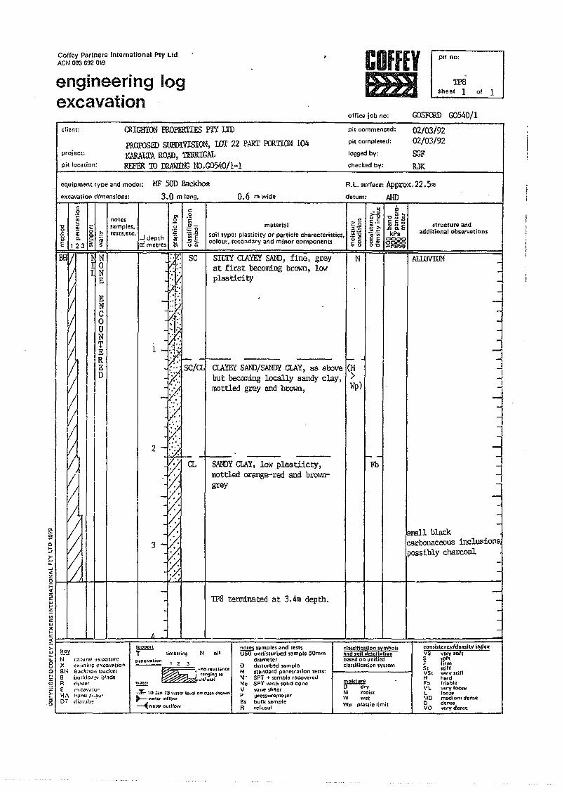
Coffey Partners International Pty LIdACN 003 692 019
engineering logexcavation
COffEYfHBI
office job no;
PIt no:
:JP8sheet 1 01 1
client;
CX>SFaID G0540/1
OOGHIDN PROPF.RTIFS PTI LID
moPOSED SUBDIVISION, wr 22 PA..ttT roRTION 104KARALTA ROAD, TF.RRlGALREFER'lD mAWltr; 00.00540/1-1
project:
pit location;
pit commenced:
pit completed:
logged by:
checked by:
02/03/9202/03/92SGFRJK
equipment type and model: NF 50D Backhoeexcavation dimensions: 3.0 m long, 0.6 m wide
A.L. surlace: Approx.22.5ndatum: MID
g c ",
"I ; noles '" .g "::" e.2 m ,,0:::
0"0 "O~to !!1 '- samples. 0 0_ material c:.!:: c c ~I
o ~ :::0,-0 .;~lUtE structure and
~ ~ ~ := tests.etc. :c '~-g::s';::
-! depth t:. soil tYpe: plasticitY or particle characterinics. .g:g kPa additional observations
E 123 a ~ m .. - colour. secondary and minor components ~c 0000II: metres <;, ->o ~ E8 0" 00000"0 -Ne-')t;t
1 E
1
ClAYEY SAND/SANDYCLAY, as above ~M -I
but beccmiug locally sandy clay, >mottled grey and brown, I~p)
..,....~:.I' ~i
2 ~'::':'.' .:-'. CL.~);
-f(;
3
n~E
~~
SILTY CIAYEY SAND, fine, grey I ~1at first becomingbrown, lowplasticity
1--'Fb
ALLUVIUM -J
1.,I
-'-!
1I-i
1J-1~
SANDYCLAY, 10\</ plast;i.icty,mottled orange-red and brown-grey
-
IJsr.al1 black
,carbolJaceous inclusionspossibly charcoal
of--'>f-"'--'<t
~I II III I I I It 4 I I I I I I~za:'"..~~'"z...~I l I I I I {I J J , I I I I =1=- i i i t
---. /,
SUD:JOnT--~I !:!Y
u..
8Q,..:!:g;:5:.J
timblr;ngNXBHBREH/\D-:'
IHHuta1 ':!'sOOSUfeexi5ti,'~ "C-":ci1',,,nion6at:\no.} b\:cketbtll!dO/~.r i}l~detipllt:r11'lo;Ca..·.I~vpr'iHIU .,:..,,~.dj,;uub~ ..
TP8 terminated at 3.4m depth.
-
--
-
N nil~ samples and [cstsU50 undisturbed ,ample 50mm
diametero dIsturbed samplei\t standard penetration te$ts~'II. SPT + SOnl()le recovered~c SPT with solid coneV vane sh"!'DI'P pre'5Surerrle\erBs bulk ...mpleR te[u5iJl
eonslstcnr;.v/donsity indo'CVS very sohS sohF li,mSt stirtVS, very stHIH hOldrb: lriableVL ~~rvlooseL loose\10 mediumdenseo d!:nseVO "IeiV dense
pentwuion ~____ ,23
~n""UIl.ncefangillg: '0fttusal
-%- H1J4,t' 78 """U:r level on. a'::J:!!' ""ow"~w&l~r Infrow
~Vla:'i!t oUltrO'o'Y
~
c:13uificallon symbolsand soil dt$crletionbased on UOit U!'dc:IClssiriC:8tion 'Sy~cem
moistureO--;;;:yM mo.srW wetWI> plaslie limil
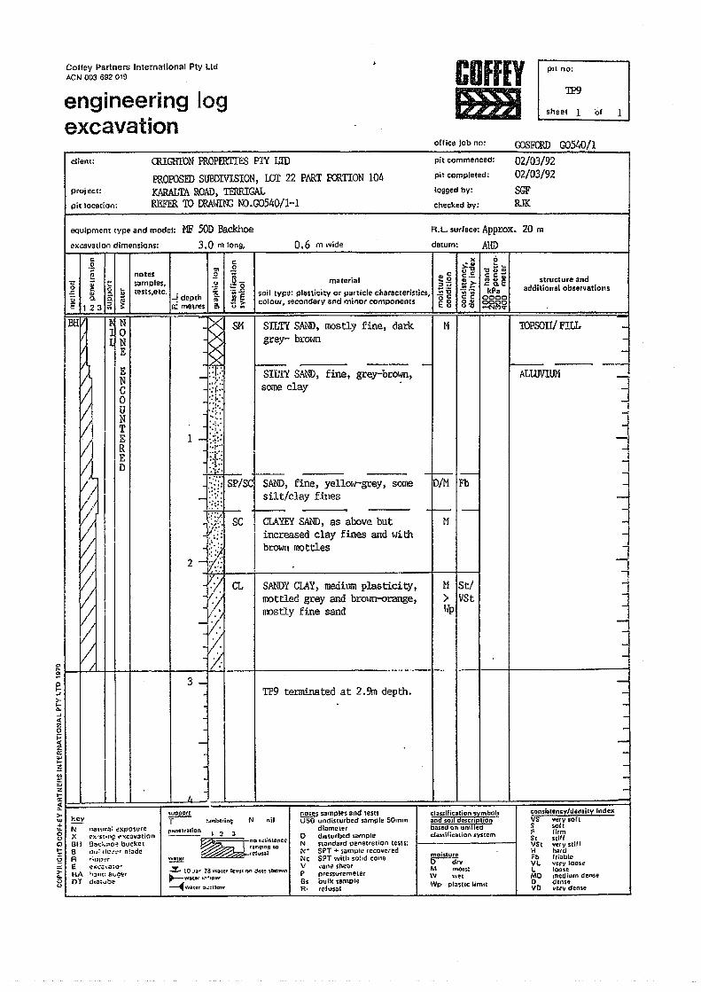
COffEYImlI
Cof1ey Partners International Pty LIdACN 003 692 019
engineering logexcavation
office job no'
pH 00;
'lP9
sheet 1 'of 1
msroID G0540!1client:
project:
pit location:
QUGHfON PROPERTIES PlY LIDPRorosED SUBDIVISION, WI' 22 PART KRTION 104KARALTA ROAD, TERRIGALREFER TO E:«AWIN:;IIn.G0540/l-1
pit commenced:
pit completed:
logged by:
checked by:
02/03/9202/03/92SGFRJK
equipment type and model: NF 500 Backhoeexcavation dimensions: 3.0 m long, 0.6 m wide
R.L. surface: Approx. 20 m
datum: AltDc.g c x 0
'"0.,I ~ e
notes:.:"' 't)Z~
-" Lv"o
samples. ~material
.. e c.5. c e Oil~ ~ g ~ t:O
~o :;~ ~ 8. E structure and
" tests,etc, '::e::::I";;
'" ~ 0. ~~ depth ~ soil type: plasticity or particle characteristics ...- ";; ow; kPa additional observations
~w't)
;:: 123;;; ex: metres 6'1 .!!> colour. secondary and minor components • '0 g c C 0000v ~ Eu 8~ 0000
--NMq-
BHVI ~ 8M I SILTY SA11lD. mostly fine, dark I M I I I 1OPSOnt FILLN grey- brown
liE· I~ ~.}; I SILTY SAND, fine, grey-brown, -I t I I ALWVIilll
g J:t: some clayU '::'"~ - ~~.j:.~~ 1 i'I~ LE :.1..:
D :};~ SF!1 SAlOl, fine, yell00-grey,";;' ivMIFb.::::: silt/clay fines
I I :Iif SC I aAYEY SAL'ID,as above but i-M I-
I '~<I I increased clay fines and with~<l.l brown mottles
2 f7~"~:"CL II SANDYCL.<\Y,medium plasticity. I M ISt/l' mottled grey and brolm-orange, > VStf, "",,'y fine sand "I>
1/'/
/:-~-t---+---------_ .....--.--1-.. ..--3-1
TP9 terminated at 2.9m depth.~or-,J
>-..."'-.J<t:;:a~:;:e::'"...~III,,;
'"z
~ 1==::::=:::::=~~ key... -u.. l\! natur:J: ~Xl'o'$l1re8 X !,,~·:s.tln~ ~"(cav3tlonQ BH 9ac~.:lo~bucket!;: 8 E)IJ:·cre ....~·r t:l~ade5 A "~UI)·"!"2 E "!x..:~.....:HQ-t HA l_Jnt: a ...e~t8 DT dU)l.sbe
------
I 1 4I
",uJ)oc.mi ~.fflbil'ing N "iI
cons:istencvldensily indexV5 Yery,ofl5 soltF firm51 StillVSt very stiJrH hatdFb fri.bleVl very roost!L looseMD rnedluR'\ dens.eo dens.V 0 "ery dense
-
_Ii
~
~1
II
~
~
iIl1I1-,j
f
-
I~ s.mpl.s and le'lSU50 u"dis,utbed sample 50m",
diametero d'5tutbed snmpleN st\lJl(jard penetration tests:~.. SPT + SiJ.mple reco\l~(ed;\Jc SPT with 5Q~ld coneV ~{ln~ shearP r>ressvfenlOlerBs oull<1ampliR· tQ'uSO:E
cl:lsslfieation symbolsand sod descriptionband on unWedclauifiC:::J\ion !:'iStem
penetr;,ion l 2 3
~no w;>t •• c.r~nql(1g 10
te:usal moistureo---<fryM mOIS';\V welWp p'aSlie limtt
~~ 10 ,.)i)!"" 1'; WaUl ~Vf' 4)t'l j.ttt" shew"~'fi.ilt.rl:"'·JOIoV
~w.cel ~.;:lIo\v
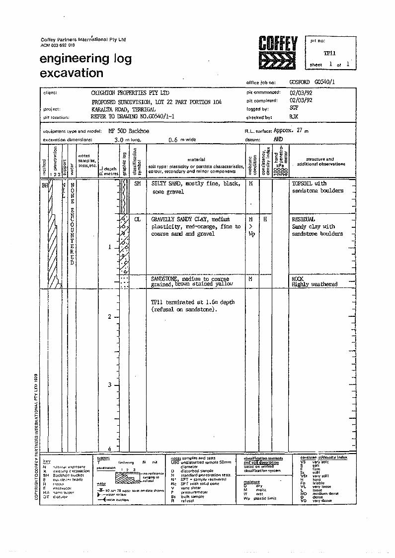
Coffey Parlne rs Intern'ational Ply Ltd,>,eN 003 692 019
engineering logexcavation
COfffYtm1
ofrice job no:
pIt no:
'.!PH
sheet 1 or 1
client:
rosFCRD G0540!1
project:
pir lOcation:
OllGHIDN PROPERTIES PrY L'IDFROFOSID SUBDlVISIOL'l, wr 22 PART PCRTION 104KARALTA ROAD, TERRIGALREFIiR 10 tRAWIN3 OO.GOS40!1-1
pit commenced:
pit completed:
logged by:
checked by:
02/03/9202/03/92SGFRJK
equipment type and model: MF 50D Backhoeexcavation dimensions: 3.0 m long. 0.6 m wide datum:
R.L. surface: Approx. 27 m
AHD
".g c:
'" .ge notes 0
E 1 ~ ~ '-samples, - co " c:.~ u_ materlal
:;:0 $ .g_ ~ n ~ tests, etc. C. :~soil type: plasticity or particle characteristics,§ 0. ~ ~ -,!depth
t;;~
i'! ..,- .~ g- 123;;; l: a:; metres ->- COlOur,secondary and minor components
CI t.>w :: u
l( b~.g ~ ~ ~c.E :i~;;l'l >- .c: a.E.~.~ kPac c 00008~ ~~~~
1'1
structure andadditional observations
N0N
. E
E
~0UNT
~ ~
~ El , D
I~Iii I
III<:>
~
-IllIII
I
1
2~
J I
3J
SM
CL
SILTY SAND, IOOstly fine, black,scxne gravel
GRAVELLY SANDY CLAY, mediumplasticity, red-orange, fine tocoarse sand and gravel
I SANDSTONE, medium to coarsegrained, brown stained yellow
N I H>I~p
1"1
TOPSOIL wi th _sandstone boulders _
JI !
jj1
""]i
~ROO< .00-=1Highly I~eathered -=j
RESIIXlALSandy clay withsandstone boulders
TPll terminated at 1.6m depth(refusal on sandstone).
i
~11l
11"~,.
t...«is~zc::w...:!ienc:w2~I I ! I I I I I I>- I I !w I ~.c., i I I~ i8 ' I
Q>-§a:>-5u
--
I I 4-
NXBHa11E
•·••;t~I:~i~~pl')'Sore~XlStlr'D £ ·«(:3v,uio.,e;)C~ho~ lJuC'k~tUui."C".:· ...' bi.jd!!,·o;)l!l
~>:r;~va:Or!1j}t'(1 ~n:tJ:~r
WI clla:lJu(t·H/~
JLOO:;lurt
T--- :imbl!'rl1\g
-
,,
N nilt.1QW samples and l!:!st'SU50 u"disturbed s.mple 50mm
diametero dis\orbed sampleN nanda ..d ~11-etTi1tiQn tests.N' SPT ... salY1ph~' recovet(!dNc SPT willl '01." coneV vane sh~arp pfe$5uremetl~t'Bs bu.lk sampleR ref",al
eQnshtB~ .v/densitv ind~l(~(vsolrS sol.F fi,mS, stillVS. very.!illH hardFb (,i.bleVL V~IV toos~L looseMO medium denseo dens.VO very dense
~
~ 1?J
~
nDICl~i$13'H::et.iU'lglf\9l0
""'''''''':<:'GG= refusal
"'* 10 ~a'" ,8 ~",)Ioir llivel nn Cl3l!!shoy..n....-w.nef "uro,""~'\"Ia:fr auHlow
classificatron svmboh:~nd soil dO$crlptionbased on umfredClassification $ysttU1\
moh:lurt"Er"<kvM moist\'II wetWp plashc limit
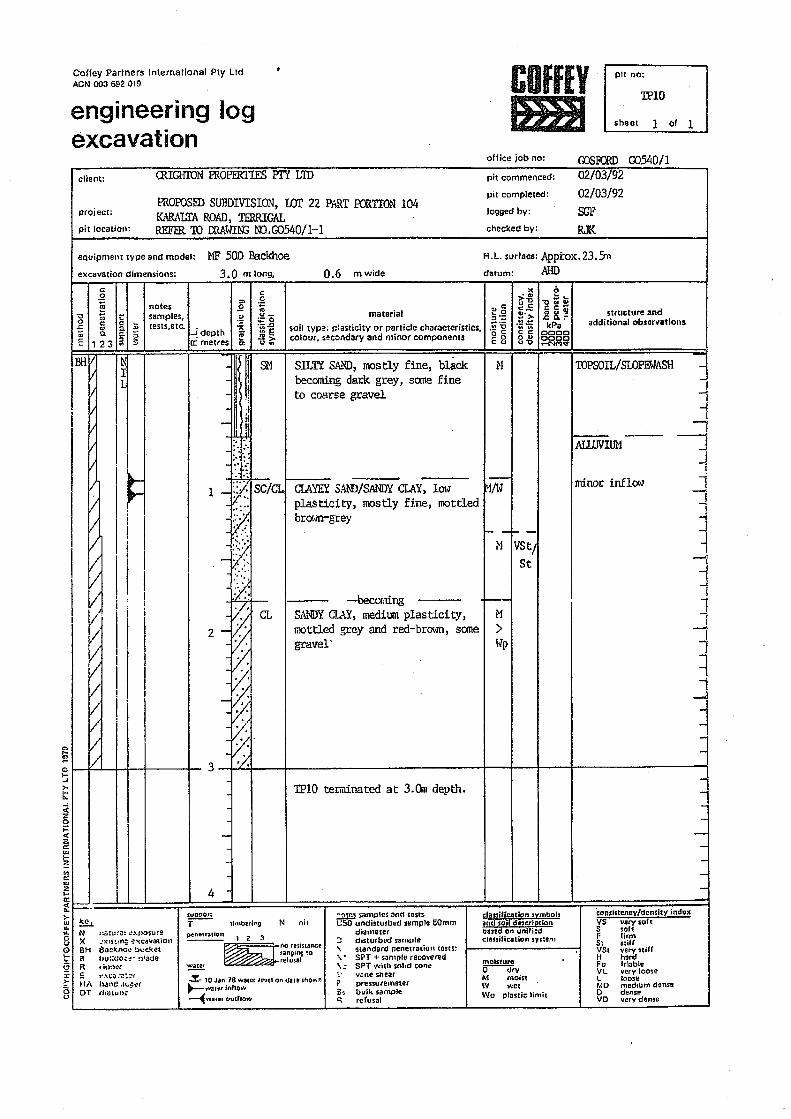
Coffey Parlners International Pty UdACN 003 692 019
engineering logexcavation
COfflYtmI
olfice job no:
pit no:
'lPIO
sheet 1 of 1
client:
OOSFaID 00540/1ffiIGHroN FROPERTIES Pl'Y LID
project:
pit location:
PROPOSED SUBDIVISION, wr 22 P/l1tT roRTION 104KARALTA ROAD, TERRIGALREFER TO CRA~.rrN:;NJ.G0540/1-1
equipment type and model: MF 500 Backhoeexcavation dimensions: 3.0 m long, 0.6 mwide
pit commenced:
pit completed:
logged by:
checked by:
02/03{9"2-02/03/92SGFRJK
R.L. surface: Apptox.23.Sndatum: MID
N
CIAYEY 5AJ.'ID!SANDYCIAY, 101.plasticity, mostly fine, mottledbrot-m-grey
hM
SILTY SA:.\ID, mostly fine, blackbecoming dark grey, some fineto coarse gravel
~+-M IVStj
St
CL-becoming
SANDYC1...AY,medilllll plasticity,mottled grey and red-brO\YO., somegtavel'
f--M>!.]p
M~hi
~a ...
~"i·:a."1'", ,.
1 -tISC/CL
~
1'\·~::~, ".....'.,. "
l.:.l::
c:.Q c >< ~
:0 0.~
~ 1 ~ ~notes £ - >-0 -ottsamples, '" ea u c
o '" .. ~<1_ material
C._:: C ;; I
~ (: :=0 ~'>- .2 K F structure and
'5 ~ 0- :! lests.etc, '-.!l soil tYpe; r.1asticity or particle characteristics:]';:: .~..~
I:!.J 0. 0- -!depth ::l. ~[ ;;~ kPa additional obsorvations
'" l!.. ..
~ :l ~ colour. s3col1dary and minor components • .~ g c c: 0000:::: 123 ~ a: metres c: u .. o " 0000C <1 u"O .-NMv
~ I~I V I I I Il:::;
t;;:
~ 4
i _ll-::::=::b! :;:::~=:;;;;;;~~~~;-l• I I
~
; I I_~_ffi I I"~bJ I I Ilr •« ....>-w......cuQ1-
§:r>-au
INI~ Ili 4 A -
I. I. I~, I
i I
I I i I. [I I1 l;] .: !
1/. I I
I ~ 'Iv' I IV I
I/
..
~ I LW ~3-fLLJ~---j- TPlO terminated at 3.Crn depth.
-
-
~
• • 4
N nil
i I:Iassification .symbolsand "Soildoscriptionb•• ell on unifledch1uificalion sys:-em
NXBHBR!OHAOT
:~fj:'~:",iJ:: ~.""f)o$ure';X:15t~n::::~,,<cav:njon6i)c~1I~~ Dl..:.ckethu~iC.:O'~-n1aoeft'~)~:!'~.;C{i~at~fhan(! .t~i=~(d~utun"
SUg:)onT--- timbtlinQ
~ 'Z 3~.or.'i".n,.
tanOlng tore'usal~
-%- 10 Jiln 78 water le".rd on d~Ie ShO....1"l
~ ...J.;JE~l"itlllo~..,~wo1~er()utfiOw
.::2.tm' samptes anrl tests~50 undisturbed sample 50mm
d,arneter~ dislurbod sample'\; 'Standard penetration tens:" • SPT + ~n,pl" recovered,\; SPT with solid cooe',; vane shear? pressutelneuu3li bulk sample<; refusal
mOisture~vM moin\V wetWp pl.stic limit
TOPSOIL!SLOPEWASH -
I-ALl1JVIUM
-,Il-,
. ~
1J
!
j
3i
ili1-.
minor inflOt~
1J
consistency/density in duxVS vervsoh:5 softF lirm51 stiffVSI very .tillH hardFa 'rlableVL very loose~ loo.eMD medium denseo dellseva very dense
---
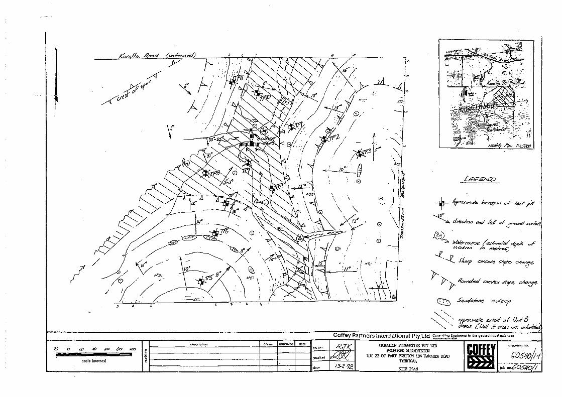
/
....._~
~ S~rfrne o<;/l"C'r
.::::~>." alrx/male e><~f. of Oil,! B......,........ O~S {~iI J1 ~5 eVe vn4
drawn approved date
. Consulting Engineers in the geotechnical !lciencesCoffey Partners InternatIonal Pty.Ltd ,,,,,,,,,,,,,,,,,,,,,_ .
D
description
wscale Ime;tresl
CRIGHTON PROPERTIES PTY LTDPROPPSED SUBDIVISION
LOT 2 B~LAR AVENUE, TERRIGALSTABILITY ASSESSMENT
REPORT NO G0652jl-AB 7 MAY 1993
COffEYIlia a a a J
68.
Coffey ·Partners Intemational Ply Ltd Consulting Engineersin the Geolechnical Sciences
p G Redm~~.BE P;DMI~EAus; - ~ .~.
C P Thorne. BE t.lEnOSc FtEAuRa C Surman. at: MEn~Sc rhl) FlE~sl MAI".YI A Blneh. DlpCE 1dAppS< flEknG K Sponesr. a~l.I"""SO PhD M......PC ThQlllSOBM G PIlUp. aE MEn.S< MlEAb"T 0 SulliYan. SA MSO Ole "'''' M1EA11$1P J H Polls, Qsqeo.l MS< IllC ..P J Hilehcox. AClS ..... IA MlM
L W O;IJrf. o~:";~;:;hOO;~N S Ma'ttOSt OAM BE. PhD MtEAuRA T Moon, uSe MSc ARSM IiUftlf
tmiAsooclatosJ G lucas, ea NIEAuSI.R J Bosl. 8E MEftgS<o "' ........I A Hosking, BE ,",.<>lEngl ore "'SAult
Coffev Partners International Pty ltdA.e.N. 003 692 019
Consulting Engineersin the gaotechnical sciences
42 Hills SireetGosford New South WaresAustralia 2250
Our Reference
Fax (043) 23 6477Telephone (043) 23 3585
Your Reference
DeleG0652j1-AB6 May 1993
BAS:EB
The ManagerCrighton Properties Pty Ltd28 Dalgetty CrescentGREEN POINT NSW 2251
ATTENTION: MR GEOFFREY COX
Dear Sir
RE: PROPOSED SUBDIVISION - LOT 2 BELAR AVENUE, TERRIGALWe are please to submit our report on geotechnical studies carried out for theabove proposed subdivision.The site is assessed to have a Medium Risk of overall slope instability and isunlikely to be affected by landslip provided development is carried out inaccordance with the recorrunendations of this report. Geotechnical constraintson residential development have been outlined in Section 4.2.Please do not hesitate to contact the undersigned should you have any queriesregarding this report.
For and on behalf ofCOFFEY PARTNERS INTERNATIONAL pry LTD
~~~.
B A STEPHENS
Soil and rOCkengineeringEny;ronmentallachnologyEngineering goo logyGroundwater hydrologyFoundation engineeringMining geol&CltnicsOem engineering......... ~_ ........ I:-""t·,.. ...~
B Ollico. end NATA Regislered Leboralories( . . i. Adelaide AlbUry,WodDnga Alsionville;, ! Brisbane Canberra Gosferd logan Cl1y'....._.".~ Melbourne Newoaslle Penrilh Perth
Sydney Townsville Wol/ongen9
'" •.• J -" ¥ .... '.~' •......... ,.:..;.. .J _.~
G0652/1-AB6 May 1993 2-. '~x,'.,.
~7:L'L'A
TABLE OF CONTENTS
1.0 INTRODUCTION 3
2.0 FIELDWORK 3
3.0 SITE DESCRIPTION 3
3.1 Geology and Subsurface Conditions
3
4
3.1 Topography, Drainage and Vegetation.
4.0 SLOPE STABILITY ASSESSMENT 5
4.1 Risk Assessment 5
4.2 Geotechnical Constraints on Development 6
4.2.1 Area for Development 6
4.2.2 Type of Structure 6
4.2.3 Foundation Types 6
4.2.4 Excavation 6
4.2.5 Filling 7
4.2.6 Retaining Walls 7
4 . .2.7 Access/Site Clearance 7
4.2.8 Drainage & Se'.....erage Di sposal 8
Important Information About Your Geotechnical Engineering Report
Explanation Sheets 1 & 2Appendix A - Engineering Logs - TPI to TP14Table 1 - Classification of Risk of Slope InstabilityTable 2 - Some Guidelines For Hillside ConstructionDrawing No. G0652/l-1 - Site Plan
IG0652/l-AB6 May 1993 3. &ml1.0 INTRODUCTION
This report presents an assessment of slope stability carried out for CrightonProperties Pty Ltd on Lot 2 Belar Avenue, Terrigal. The work was commissionedby Mr Geoffrey Cox of Crighton Properties Pty Ltd. A 1:1000 scale contourplan of the lot was provided by Cahill & Cameron Pty ltd.It is understood that development plans have not been finalisedHowever, it is understood the proposed development isapproximately 60 residential allotments. It is understood fromdrawings that the roads are to be aligned generally across thethe steeper sections of the site.
for the site.to comprisethe supplied
hillslopes in
This report assesses the sUitability of, the lot for developmentgeotechnical v.iewpoint, provides a risk assessment in relation tostability and provides geotechnical constraints for dev~lopment.
from aslope
2.0 FIELDWORK
fieldwork involved a walk over assessment,test pitting to assess surface features andwas carried out on the 4th May, 1993 by aCompany.
surface mapping and a program ofsubsurface profiles. This workGeotechnical Engineer from this
Fourteen test pits (TPI to TPI4) were excavated to depths ranging from 0.6mto 3.3m by a rubber tyred backhoe .. The locations of the test pits are shownon Drawing No. G0652/l-l, together with the results of the surface mapping.Test pit levels have been interpolated from the contour plan provided. Thetest pits were located by Cahill & Cameron Pty Ltd.Engineering logs of the test pits are presented in Appendix A, together withexplanation sheets defining the terms and symbols used in their preparation.
3.0 SITE DESCRIPTION
3.1 Topography, Drainage and VegetationLot 2 occupies an ilL" shaped area of approximately eight hectares.Topographically, the site comprises a valley with a generally north-west tonorth aspect. The terrain is moderate to steeply sloping around the centraldrainage depression which crosses the site in a north-westerly direction. Anortherly trending spur is located in the west of the site adjacent to thewestern boundary.
-..,0..01 ~·".:lf(,-'~i~ UUefnatiOnal rt~ Lrc
G0652jl-AB6 May 1993 4. 1m)]
Groundslopes at the site vary from about 3" to 7~ to the horizontal near thedrainage depression, to l5~ to 18~ to the horizontal in the higher slopes.The contour plan provided shows the site elevation to vary from about RL22mAHD in the north of the site to greater than RL70m in the south of the site.The area of the proposed residential development is generally open and wellgrassed, with the exception of an area to the east of the site and on anortherly facing slope towards the centre of the site where these areas aremoderately wooded. Heavily wooded areas with thick undergrowth, generallycorresponding to the steeper areas, are located on the properties adjoiningthe site.Existing development comprises a dwelling and horse stable located in thenorth-east of the site. Cuts of up to 3m are located to the east of the abovestructures. The horse stable appears to be founded partly on fill materialswon from these cuts.Access to the site is via a dirt track from the end of Belar Avenue located tothe north. This track appears to have been formed by cutting and filling andruns across the slope of the hill.Other man made features on the site include an existing farm dam located nearthe centre of the northern boundary.
3.2 Geology and Subsurface ConditionsThe 1:25000 Geological Map of Gosford indicates the site to be underlain bylithic-quartz to quartz sandstonet siltstone, minor sedimentary breccia;claystone and conglomerate of the Terrigal Formation.On the basis of the surface features and the subsurface conditions encounteredin the test pits, the site can be divided into two unitst namely;
+ Unit A Comprising predominantly slopewash and residualsoils overlying sandstone/siltstone rock atab.out O.7m to 1.7m depth; andComprising alluvial soils up to or greater than4.4m in depth, overlying deeply weatheredresidual soils to depths in excess of 3.3m.
+ Unit B
The approximate extent of the above units is shown on Drawing No. G0652/1-1.The subsurface profile encountered in Unit A (Test Pits 3 to 14) can besumrnarised as follows;
TOPSOILjSLOPEWASH: Comprising Silty Sand,grained, light grey andobserved"unit depth variedoverlying
fine to mediumgreYt some roots,from O.2m to a.8m;
G0652/l-AB6 May 1993 5. ImlJ
'----------------RESIDUAL: CLAY, medium plasticity, orange brown and red
brown, very stiff, observed unit thicknessvaried from 0 to 1.3m; overlying
BEDROCK: SANDSTONE and SILTSTONE, extremely tohighly weathered. Backhoe refusal on sandstonewas encountered in Test Pits 4. 6 to 10 and 12to 14.
The subsurface profile encountered within Unit B (Test Pits 1 and 2) can besummarised as follows;
TOPSOIL: Silty SAND, fine -to medium grained, light greyto grey, some roots, observed unit thicknessvaried from a.2m to a.3m; overlying
SLOPEWASH/ALLUVIUM: Clayey SAND/Sandy CLAY, fine to medium grained.medium plasticity, orange brown and red brown,observed unit thickness varied from a.7m to1.6m; overlying
RESIDUAL: CLAY, medium plasticity, red brown, orange brownand light grey, observed unit thickness wasapproximately 1m; overlying
BEDROCK: SANDSTONE, fine to coarse grained, extremely tohighly weathered, orange brown and red brown.Bedrock was encountered at depths between 2.0mto greater than 3.3m.
No groundwater inflows were observed during the test pitting. It should benoted that pits were open only for a short time and variations may occur dueto fluctuations in rainfall, temperature and other factors.
4.0 SLOPE·STABILITY ASSESSMENT
4.1 Risk AssessmentNo evidence of overall slope instability was observed during the ~alk overassessment and backhoe test pitting. Minor localised instability was observedin steep cuts upslope of the horse stable where slumping appears to haveoccurred.On the basis of the features of geology, topography and drainage presented inSection 3.0, the site is assessed as having a.Medium Risk of overall slopeinstability as defined in the attached Table 1. The risk of localisedinstability associated with future cuts and fills in assessed as moderate andcan be limited by adopting the recommendations of this report.
j _._-; .J. _ •• •...I.<.J. 'J _ .....
G0652/1-AB6 ~ay 1993 6. 1m!4.2 Geotechnical Constraints on Development
4.2.1 Area for DevelopmentFrom a slope stability viewpoint, the entire site is considered suitablefor development undertaken in accordance with good hillside constructionpractices and sound engineering principles as outline in the attachedTable 2.
4.2.2 Type of StructureFlexiblewould bedesignedsuspended
structures of timber, brick veneer or similar constructionpreferred on the Unit A hl1lslopes. Development should beto accommodate natural slope profiles with split level ordesigns so as to limit the need for slope modification.
There are no particular geotechnical constraints on the type ofstructures Within the flat Unit 8 alluvial area or for structuresfounded on rock on the Unit A hillslopes, provided they are supported onfootings designed and constructed in accordance with AS2870 "ResidentialSlabs and Footings".
4.2.3 Foundation TypesFoundations should be designed and constructed in accordance with therecommendations and advice of AS2B70 "Residential Slabs and Footings".Further site specific assessment will be required to assess foundationcharacteristics within the Unit 8 alluvial soils. In particular,shrink-swell potential of these soils should be addressed due to thethickness of alluvial and residual soils.Pad/strip 'or pier and beam footing systems are considered appropriatefor split level structures on Unit A moderate to steep hillslopes.Stiffened raft or piered slab footing systems may also be adoptedprovided the resulting slope modifications comply with the geotechnicalconstraints set out below. It is recommended that foundations forstructures on slopes in excess of 4H:lV (14°) be taken to rock.Strip/pad, stiffened raft or piered footing systems would be appropriatefor residential structures located within the flat Unit B alluvialareas.
4.2.4 ExcavationExcavations in soil should preferably not exceed 1.0m depth and batteredno steeper than 2H:IV and protected from erosion. .Excavations greaterthan 1.Om should be supported by a properly designed and constructedFetaining wall.
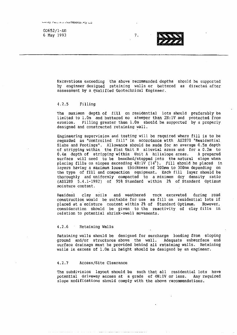
"-UII:;;'j .-",~ H '~'''; u·,t:::"flai.IOnal r~y t.~G
G0652/1-AB6 May 1993 7. tmI
Excavations exceeding the above recommended depths should be supportedby engineer designed retaining walls or battered as directed afterassessment by a qualified Geotechnical Engineer.
4.2.5 FillingThe maximum depth of fill on residential lots should preferably belimited to 1.Om and battered no steeper than 2H:IV and protected fromerosion. Filling greater than 1.Om shoUld be supported by a properlydesigned and constructed retaining wall.Engineering supervision and testing will be required where fill is to beregarded as "controlled fill" in accordance with AS2870 lIResidentialSlabs and Footings". Allowance should be made for an average O.Sm depthof stripping within the flat Unit B alluvial areas and for a a.2m toO.4m depth of stripping within Unit A hillslope areas. A preparedsurface will need to be benched/stepped into the natural slope whenplacing fills on slopes exceeding 4H:IV (140). Fill should be placed inlayers having a maximum loose thickness of 200mm to 300mm depending onthe type of fill and compaction equipment. Each fill layer should bethoroughly and uniformly compacted to a minimum dry density ratio(AS1289 5.4.1-1982) of 95% Standard within 2% of Standard Optimummoisture content.Residual clay soils and weathered rock ~xcavated during roadconstruction would be 5u~table for use as fill on residential lots ifplaced at a"moisture content within 2% of Standard Optimum. However,consideration should be given to the reactivity of clay fills inrelation to potential shrink-swell movements.
4.2.6 Retaining WallsRetaining walls should be designed for surcharge loading from slopingground and/or structures above the wall. Adequate subsurface andsurface drainage must be provided behind all retaining walls. Retainingwalls in excess of 1.Om in height should be designed by an engineer.
4.2.7 Access/Site ClearanceThe subdivision layout should be such that all residential lots havepotential driveway access at a grade of 4H:lV or less. Any requiredslope modifications should comply with the above recommendations.
....u" ..y ,-a'h,,,'-S .(J(tlrnaUOncu rJly LlO
G0652/1-AB6 May 1993 8. Imi
4.2.8 Drainage and Sewerage DisposalStormwater should be prevented from ponding adjacent to structures. Allcollected stormwater runoff should be piped into a street or inter-allotment drainage system that discharges into existing watercourses ina controlled manner that limits erosion.Domestic effluent should be connected to.a reticulated sewerage systemor to a pump-out septic system. There should be no on-site disposal ofdomestic effluent.
zt:/ ~.For and on behalf ofCOFFEY PARTNERS INTERNATIONAL PTY LTD
As the client of a consulting geotechnical engineer. youshould know that site subsurface conditions cause moreconstruction problems than any other factor ASFElfheAssociation of Engineering Firms Practicing in theGeosciences offers the following suggestions andobservations to help you manage your risks
A GEOTECHNlrAL ENGINEERING REPORT IS BASEDON A UNI~UE SET OF PROJECT-SPECIFIC FACTORSYour geotechnical engineering report is based on asubsurface exploration plan designed to consider aunique set of project-specific factors. These factorstypically include: the general nature of the structureinvolved, its size. and configuration; the location of thestructure on the site: other improvements. such asaccess roads. parking lots. and underground utilities:and the additional risk created by scope-of-servicelimitations imposed by the client. To help avoid costlyproblems. ask your geotechnical engineer to evaluatehow factors that change subsequent to the date of thereport may affect the report's recommendations.
Unless your geotechnical engineer indicates otherwise.do not use your geotechnical engineering report
• when the nature of the proposed structure ischanged. for example. if an office building will beerected instead of a parking garage. or a refrigeratedwarehouse will be built instead of an unrefrigeratedone;
• when the size. elevation, or configuration of theproposed structure is altered; .
• when the location or orientation of the proposedstructure is modified;
• when there is a change of ownership; or• for application to an adjacent site.
Geotechnical engineers cannot accept responsibility forproblems that may occur if they are not consulted afterfactors conSidered in their report's development havechanged.
SUBSURFACE CONDITIONS CAN CHANGEA geotechnical engineering report is based on condi-tions that existed at the time of subsurface exploration.Do not base construction decisions on a geotechnicalengineering report whose adequacy may have beenaffected by time. Speak with your geotechnical consult-ant to learn if additional tests are advisable beforeconstruction starts. Note. too. that additional tests maybe required when subsurface conditions are affected byconstruction operations at or adiacent to the site, or bynatural events such as floods. earthquakes, or groundwater fluctuations. Keep your geotechnical consultantapprised of any such events.
MOST GEOTECHNICAL FINDINGS AREPROFESSIONAL JUDGMENTSSite exploration identifies actual subsurface conditionsonly at those points where samples are taken. The datawere extrapolated by your geotechnical engineer whothen applied judgment to render an opinion aboutoverall subsurface conditions. The actual interfacebetween materials may be far more gradual or abruptthan your report indicates. Actual conditions in areasnot sampled may differ from those predicted in yourreport. While nothing can be done to prevent suchsituations. you and your geotechnical engineer can worktogeth~r to help minimize their impact. Retaining yourgeotechnical engineer to observe construction can beparticulariy beneficial in this respect.
A REPORT'S RECOMMENDATIONScAN ONLY BE PRELIMINARYThe construction recommendations included in yourgeotechnical engineer's report are preliminary. becausethey must be based on the assumption that conditionsrevealed through selective exploratory sampling areindicative of actual conditions throughout a site.Because actual subsurface conditions can be discernedonly during earthwork. you should retain your geo-technical engineer to observe actual conditions and tofinalize recommendations. Only the geotechnicalengineer who prepared the report is fully fam i1iar withthe background information needed to determinewhether or not the report's recommendations are validand whether or not the contractor is abiding by appli-cable recommendations. The geotechnical engineer whodeveloped your report cannot assume responsibility orliability for the'adequacy of the report's recommenda-tions if another party is retained to observe construction.
GEOTECHNiCAl SERVlCES ARE PERFORMEDFOR SPECIFIC PURPOSES AND PERSONSConsulting geotechnical engineers prepare reports tomeet the specific needs of specific individuals. A reportprepared for a civil engineer may not be adequate for aconstruction contractor or even another civil engi neer.Unless indicated otherwise. your geotechnical engineerprepared your report expressly for you and expressly forpurposes you indicated No one other than you shouldapply thiS report for its intended purpose without firstconferring with the geotechnica I engineer. No partyshould apply this report for any purpose other than thatoriginally contemplated without first conferring with thegeotechnical engineer.
GEOENVIRONMENTAL CONCERNSARE NOT AT lSSUEYour geotechnical engineering report is not likely torelate any findings. conclusions, or recommendations
about the potential for hazardous materials existing atthe site. The equipment, techniques. and personnelused to perform a geoenvironmental exploration differsubstantially from those applied in geotechnicalengineering. Contamination can create major risks. Ifyou have no information'about the potential for yoursite being contaminated. you are advised to speak withyour geotechnical consultant for information relating togeoenvironmental issues.
A GEOTECHNICAL ENGINEERING REPORT ISSUBJECT TO MISINTERPRETATIONCostly problems can occur when other design profes-sionals develop their plans based on misinterpretationsof a geotechnical engineering report. To help avoidmisinterpretations. retain your geotechnical engineer towork with other project design professionals who areaffected by the geotechnical report. Have your geotech-nical engineer explain report implications to designprofessionals affected by them. and then review thosedesign professionals' plans and specifications to seehow they have incorporated geotechnkal factors.Although tertain other design professionals may be fam-iliar with geotechnical concerns, none knows as muchabout them as a competent ~eotechnical engineer.
mates was not one of the specific purposes for which itwas prepared. In other words. while a contractor ma:ygain important knowledge from a report prepared foranother party. the contractor would be well-advised todiscuss the report with your geotechnical engineer andto perform the additional or alternative work that thecontractor believes may be needed to obtain the dataspecifically appropriate for construction cost estimatingpurposes.) Some clients believe that it is unwise orunnecessary to give contractors access to their geo-technical engineering reports because they hold themistaken impression that simply disclaiming responsi-bility for the accuracy of subsurface information alwaysinsulates them from attendant liability. Providing thebest available information to COntractors helps preventcostly construction problems. It also helps reduce theadversarial attitud~s that ca n aggravate problems todisproportionate scale.
BORING LOGS SHOULD NOT BE SEPARATEDFROM THE REPORT '*Geotechnical engineers develop final boring logs basedupon their interpretation of the field logs {assembled bysite personnel) and laboratory evaluation of fieldsamples. Geotechnical engineers customarily includeonly final boring logs in their reports. Final boring logsshould not under any circumstances be redrawn forinclusion in architectural or other design drawings,because drafters may commit errors or omissions in thetransfer process. Although photographic reproductioneliminates this problem. it does nothing to minimize thepossibility of contractors misinterpreting the logs duringbid preparation. When this occurs. delays. disputes. andunanticipated costs are the all-too-frequent result.
To minimize the likelihood of boring log misinterpreta-tion. give contractors ready access to the completegeotechnical engineering report prepared or authorizedfor their use. (If access is provided only to the reportprepared for you. you should advise contractors of thereport's limitations. assuming that a contractor was notone of the specific persons for whom the report wasprepared and that developing construction cost esti-
READ RESPONSIBILITY CLAUSES CLOSELYBecause geotechnical engineering is based extensivelyon judgment and opinIon. it is far less exact than otherdesign disciplines. This situation has resulted in whollyunwarranted claims being lodged against geotechnicalengineers. To help prevent this problem. geotechnicalengineers have developed a number of clauses for use intheir contracts. reports. and other documents. Responsi·bUH')'clauses are not exculpatory clauses designed totransfer geotechnical engineers' liabilities to otherparties. Instead. they are definitive clauses that identifywhere geotechnical engineers' responsibilities begin andend. Their use helps all parties involved recognize theirindividual responsibilities and take appropriate action.Some of these definiti'le clauses are likely to appear in,your geotechnical engineering report. Read themclosely. Your geotechnical engineer will be pleased togive full and frank answers to any questions.
RELY ON THE GEOTECHNICAL ENGINEERFOR ADDITIONAL ASSISTANCEMost ASFE·member consulting geotechnical engineer-ing firms are familiar with a variety of techniques andapproaches that can be used to help reduce risks for allparties to a construction proiect. from design throughconstruction. Speak with your geotechnical engineer notonly about geotechnical issues. but others as well. tolearn about approaches that may be of genuine benefit,You may also wish to obtain certain ASFE publications.Contact a member of ASFE of ASFE for a complimentarydirectory of ASFE publications.
* For further information on this aspect reference should be mad~ to "Guidelines for theProvision of Geotechnical Information in Constnlction Contracts" published by the Instittltionof Engineers Australia, National Headquarters, Canberra, 1987.
ASP ETHE ASSOCIATIONOF ENGINEERING FIRMSPRACTICING IN THE GEOSCIENCES
8811 COLESVILLE ROADISUITE GI06/SILVERSPRING. MD 20910TELEPHONE: 301/565,2733 FACSIMILE: 301/589-2017
Copyright 1992 by ASFE, fnc Unless ASFE grants specillc peormission to do SO. duplication ollhls document by any means whatsoever is expressly prohibited.Re-use 01 tile wordong In 1015document. in whole or In part. also is expressly prohibited. and may be done only with the express permission 01 ASfE or ror purposes
of review or scholarly research.
tlC""I'<t>"l.\11 "\'J
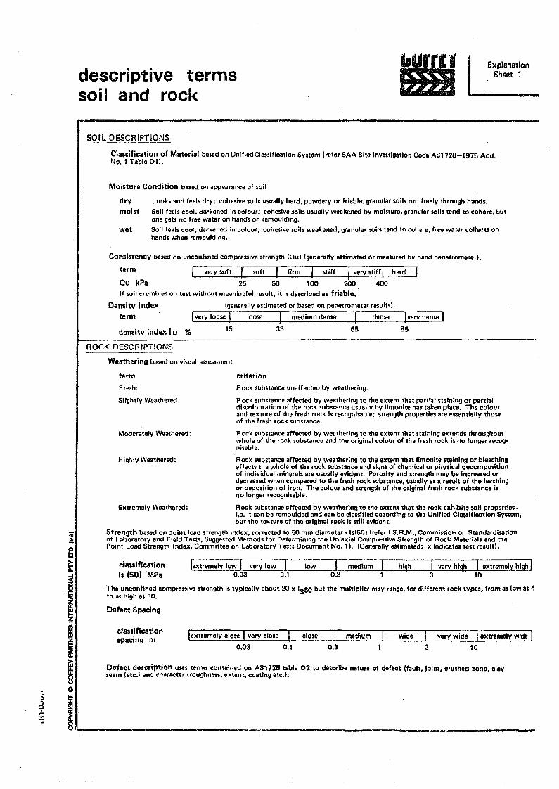
§t
I~
i~
iii~
descriptive termssoil and rock
bUrrt'1&JJ
ExplanationSheet 1
SOIL DESCRIPTIONS
Classification of Material based on Unified Classification System (refer SAA Site InvQtlgatlon Code AS1726-1975 Add.No.1 Table 011.
Moisture Condition based on appearance of soli
drymoist
l.ooks and feels dry: cohesive salls usually hard. powdery or friable. granular salls run freely throulltl hands.Soil feels cool. derkened in colour; cohesive soils usually weakened by moinure. granular soils tend to cohere. butone gets no free water on hands on remoulding.Soil feels cool, darkened in colour; cohesive soils weakened. granular soils tend to cohere, free water collects onhands when remoulding.
wet
Consistency based on unconfined compressive strength IQuilgenerally estimated or measured by hand penetrometer!.
term J very soft I soft I firm I stiff I very stiff I hard'
Ou kPa 25 50 100 200 400If soil crumbles on test without meaningful result, it is described as friable.
Density Index (generally estimated or based on penetrometer resultsl.
term j very loose I loose I medium dense I dense
15 35 65 85density index I0 %
ROCK DESCRIPTIONS
Weathering based on Visual assessmenl
termFrssh:
Slightly Weathered:
criterionRock subsumcs unaffected by weathering,
Rock substance affected by weathering to the extent that partial staining or partialdlscolouration of the rock substance usually by limonite has taken place. The colourand texture of the fresh rock is recognisable; strength propertill$ are essentially thoseof the fresh rock substance.
Rock substance affected by weathering to the extent that staining extends throughoutwhole of the rock substance and the original colour of the fre5h rock is no longvr reeog'nisable.
Moderately Weathered:
Rock substance affected by weathering to the extent that limonite staining or bleachingaffects the whole ot the rock substance and signs of chemical or physical decompositionof individual minerals are usually evident. Porosity and strength may be increased ordecreased when compared to the fresh rock SUbstance. usually as a rewlt of the leachingor deposition of iron. The colour and strength of Ihe original fresh rock substance isno longer recognlsable.
Extremely Weathered: Rock substance affected by weathering to the extent tbat the rock exhibits soli proP/lrties.i.e. it can be remoulded and can be classified according to the Unified Classification System.but the texture of the original rock is still evident.
Strength baSlld on point load strength index. corrected to 50 mm diameter ·ls(50l [refer I.S.R.M .. Commission on Standardisationof Laboratory and Field Tests. Suggested Methods for Determining the Uniaxial Compressiva Strength of Rock Materials end thePoint Load Strength Index. Committee on Laboratory Tests Document No.1 I. fGenerallyestimated: x indicates test result!.
Highly Weathered:
ctassificatlonIs (50~ MPa
lextremely I~W I very low I low I: medium I hiS" I very hili!'! I extr8lTlelx high I0.03 0.1 0.3 1 3 10
The unconfined compressive strength is typically about 20 x Is50 but the multi pilar may range. for different rock ;ypes, from as fow as 4to as high n 30.
Defect Spacing
classificationspacing m lextremely close Ivery close I close I medium I wide I very wide Iextremely wIde I
0.03 0.1 0.3 1 3 10
.Defect description uses termt contained on AS172G teble 02 to describe nature of def8ct !fault. joint, crushed zone, clayseam letc'! and Character (roughness, extent. coating atc.):
:i~~<Xl
@
~
~~ - -. ..~~.. ft .. ." ~.t''''lo.S4 Pi
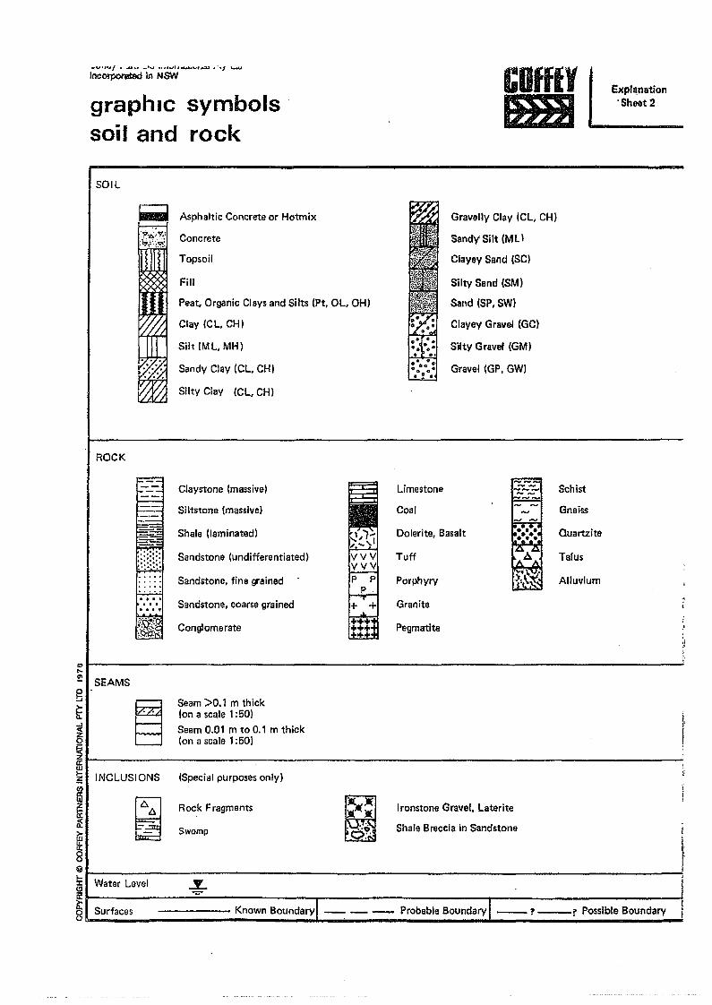
_vo,oGr/ I .... ,~ _'v ••• hJlt .........""'~ ~ "1 low+U
IncOl'pOl'atOO in NSW
graphic symbolssoil and rock
COffEYJmJ
expl~nation.Sheet 2
SOIL
Fill
Peat. Organic Clays and Silts (Pt, OL, OH)
Clay (CL, CHI
Silt [ML, MH)
Sandy Clay (CL, CHI
Silty Clay (CL, CHI
_ Asphaltic Concrete or Hotmix Gravelly Clay (CL, CHI
Sandy' Silt (MLI
Clayey Sand (SCI
Silty Sand (SM)
Sand (SP, SW)
Clayey Gravel (GC)
Silty Gravel (GM)
Gravel (GP, GW)
r-~.~·::!~flConcrete.c:7~"~
Topsoil
ROCK
r::-==tClaystone [massive) limestone Schist
Siltstone (massive) Coal Gneiss
Shale (laminated) Dolerite, Basalt Quartzite
Sandstone (undifferentiated) Tuff
~
Talus"1; •
Sandstone, fine grained Porphyry ·M':~ Alluvium
Sandstone, coarse grained Granite
Conglomerate Pegmatite
;1 SEAMSc!:i
~
Seam >0.1 m th ickIon a scale 1:50)Seam 0.01 m to 0.1 m thick(on a scale 1:50)
~
i~I""I-N-C-L-U-S-IO-N-S-------:-------------------------------:
(Special purposes only)
IIf~8 ,; I Water Level~ ,6:! i
~ -, ,~h
~
Rock Fragments
~
~;·d~·
Ironstone Gravel, laterite
Shale Breccia in SandstoneSwamp
Surfaces
..,......Y...
------ Known Boundarvl -- -- _ Probable Boundary I -? _1' Possible Boundary
~ .ct) CJ).
,I
t: ;:+ en o -h -h _. CD - 0-» _."'C
::S."t
J<:
m~
.2
.~'
O _.-
cg><
..... _. o :J):>
.-
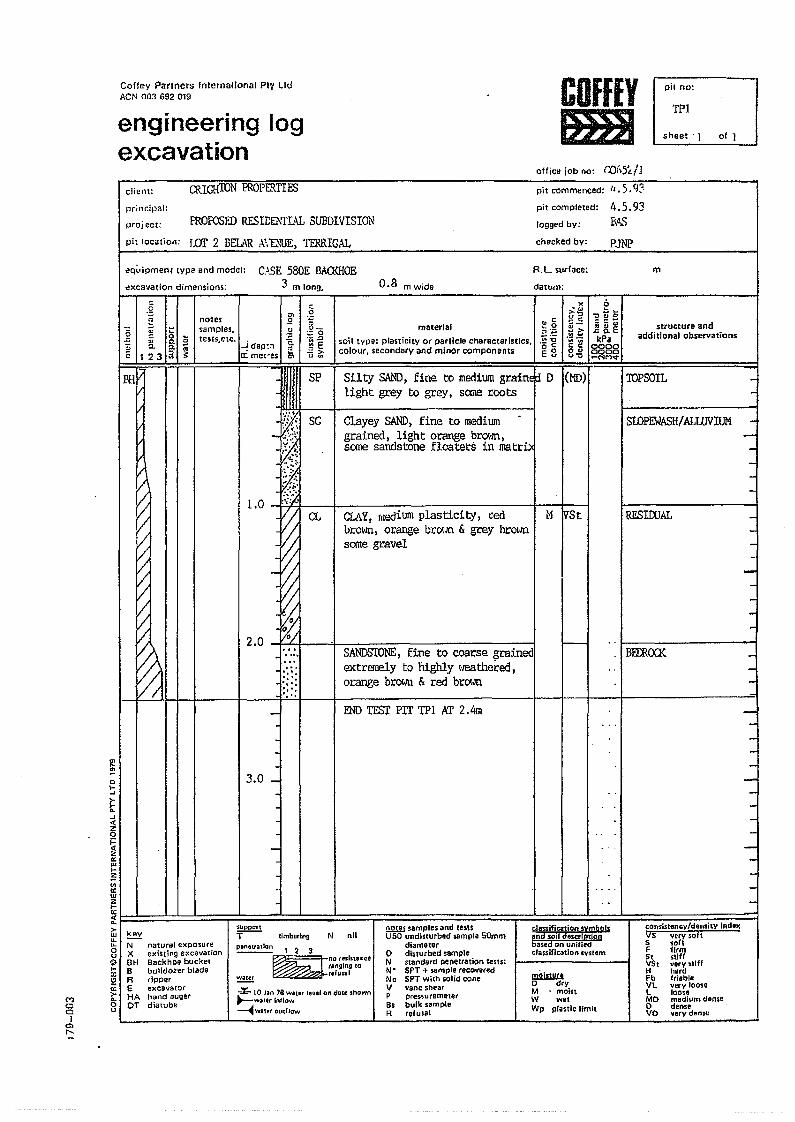
Coffey Partners tntemalional PIV lidACN 003 692 019
engineering logexcavation
COffEYFSI
pit no:
TP.I
sheet· .1 of 1
office jOb 00: r:()I':'Sl./l
cliem: CRIGH'fON PROPERTIESprincipal:
proj ect:
pit location:
FROFOSffi RESrr:E.-lrLa:L SUBDIVISION
1m 2 BELAR A'.D1JE, TERRIGAL
pit commenced: 1'.5. q::-pit completed:
Jogged by:
checked by:
1~.5.93BA.)
PJNP<lquipmenl tYpe and model: C.1SE580E BAa<HOE
':lJ m long. 0.8 m WIdetlxcavation dimension~:
R. L. surface: mdatum:
.g'" .g
-I ~ ~ notes .2samples. .g ~-
~ ;i & ~ teS1S,etc.;;:0
0.._~
:; =r.. o.ra ~dep:'! .. ~ E" 123 a ;: a: me!"es ~ =>
u'"
SP
ENDTEST PIT '[PI AT 2.4m -
material~o;1typu: plasticity or particle characteristics,colour, secondary and minor componenu
b=~-c:"t.I<:~-l!:I ;:; 4.1
.J:: 0. EkPa
00000000_NMv
".'""''0~t:~.~';;;;.V;c <:0'"<>'0
.. c:~o;:~.!:!"Do t:E8
structure andadditional observations
(')cc)
Qlr-.
BHVI I I 1 I
1.0
2.0
-~
Silty SAND, fine to medium graind:! D I(HI»light grey to grey, some roots
sc Clayey SAND, fine to mediumgrained, light orange brC»Jn,some sandstone floaters in matr:b<
TOPSOIL -
SlDPEWASH! ALWVIUM -
r; -3.0 _
CL CLAY, medium plasticity, redbrO\VI1,orange brOlJn & grey brOlmsane gravel
H IVSt &ESlOOAL -
o~~.......«zoj:<tZ
'"wI-:;<II
'"WZI-~I I I I I I I I I>- i Iw I keY I I I I~ I =18 I
oI-:x:\:I;;;>-...ou
-
-
SANDStONE,fine to coarse grainedextremely to nighly \'leathered,orange browl1 & red brOl.ltl
I----l .. [ -IBErnCXX -
N nil!!!ll!l samples and te5lsUSO undisturbed sample SOmm
diarnetero disturbed sampleN standard penelration tests:N' SPT + sample 'eco~ .. edNc SPT with solidcon.V vane shearP pl'essuremeterBs bulk sompleR refusal
consistency/density Ind.xV5 ,"ry soft550ftF firm5t stiffVSt verystillH hardFb f,iableVL very loos.L loo.eMO medium den.eo den,.VO "ery dense
classification symbolsand Joil descrlptlqpbased Dn unifiedcfas$Uication systfM
moistureo dryM • moinW wetWp plastic limit
'SupportT-- timbllring
natural eXp05U(eexistil"'lg excavatiOnBackhoe bucketbulldozer bladeripperexcaV3mrhand augerdiatube
NXBHBREHAor
~ \23~nor~'i ... nce
ranging tordUSiI
...:... 10 Jtn 18 waClI!'r llenl on dlUI shown"'--wattr inflow~.....,atrr olJcllow
~
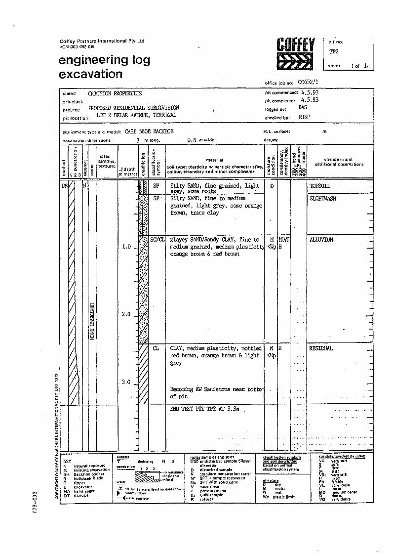
Coffey Partners International Ply LtdACN 003 692 019
engineering logexcavation
COfffYtmlI
office job no: rll65%!1
pit no:
TP2sheel 101 1·
client:
principal:
CRlGHIDN PROPERTIF.S
m
ffiOPOSEDRfSIDThTIAL SUBDIVISIONpit location: tor 2 BEf.AR AI,'lli'UE, TERRIGAL
pit commenced: 4.5.93pit completed: 4.5.93
BASproject: logged by:
checked by: P.lliP
equipment type and model: C.l$E 580E BAa<HOEexcavation dimensions: 3 m long. 0.8 m wide
R.L. surface:
datum:
'"...~0.....J
>-Ii:....0(z01=otzc::......~..c::wZ...c::«"->wu.u.0<.>€)0-J:\:Ii:
M>-..
0 00 vI
""r--..'-
:nnotes I 0sample,. ~tests,etc.. -a
~ depth '"l:C metres c,
~N natural exposureX existing:eXt8vstionBH Backhoe bucketB bulldozer bladeR dppe<E excavatorHA hand augerOT diatube
El;>.
ffi~C"l
2
!
'J
2.0
~CL
3.0
.
-
,§;;'-'-:;:0
Y:ii .n~['-'~
SP
Sp·
materialsoil tYpe: plasticity or particle characteristics.colour. secondary and minor compOnents
Silty SA!."ID,fine grained, light--:ey, serne rOOts .Silty SAJ.'ID,fine to mediumgrained, light grey, some orangebrown, trace clay
G.layey SAND/Sandy CI.AY, fine tomediwn grained, medium plasticitjorange brown & red brown
CI.AY,medium plasticity, mottledred brown, orange brown & lightgrey
Becoming 'EM Sandstone near. bottOliof pit
END TEST PIT TP2 AT 3.311
f,ugPQrtT-- tlmberl"ll
~ ,amples and testsUSO undisturbed sample 50mm
diametelo disturbed sampleN standard penetration tens:N' SPT + samplerecoveredNc SPT with solidconeV vane shearP premlfemeter8. bulk .ampleR refu,al
~.Q,,-=:0·2 g"u
1'1 IMO/e<WpH
M IH<Wp
D
(,:,~
-0 .....r:.",-~~EkPa
~g~
N nilclassificationsymbol.2nd $oil doscripdonbased on Ltnifiedclassifica\ion system~12:J
~nor~ll ... n<.rangln9 '0refus.al
...¥- 10 Jlln 78 watu Iwol OJ) date shOwn~wlter inllow~watl!J outlloW'
~ mofS1ureo-dryM moistW wetWp plastic limit
x.">--0u",C._
.~~ec0"u'\:l
structure andadditional observations
TOPSOIL -SLOPEWA$H -
AlJ1JVIUM -
-RfSlOOAL -
--- - -
_ ..... .-
con.l.to"cy{d.",lty indeMVS Vtry,oftS softF firm51 stiffVSC very stiffH hotdFb friableVL very 1001 •L looleMo medium den.eo denseVO very dense
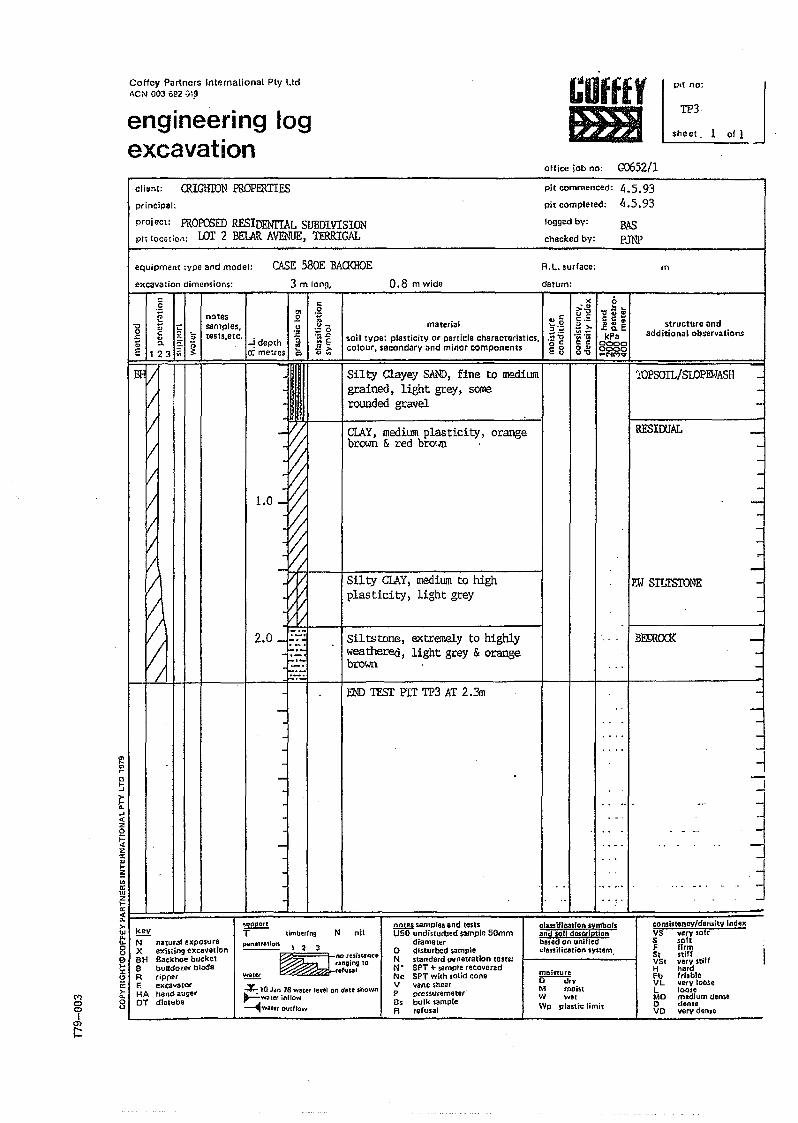
CoHey Parlners Inlernalional Ply LId"eN 003 ;;~2.);~
engineering logexcavation
COffEYImlI
PlI no:
TP3sheet, 1
office job no: G0652/1
~Jclient: CRIGHroN PROPERTIES pit commenced: 4.5.93
pit compleled: 4.5.93logged by: BAScliecked by: pJNP
project: ffi.OPOSED RESIDENITAl. SUBDIVISIONpit location: wr 2 BELARAVEi\W, TIRRIGAL
principai:
equipment ;ype 3r'1d model: CASE 58QE BAa<HOE3 m long, 0.8 mwide
R.L, surface:
datum:excavation dimension'$:
m
.g c
'" .g2 notes .2 "
1l I ~ ~ ~ samples, .!:!u_;:;0
J::. eJ ,....:> tests,etc. ~ .- 1:>!j 0. ~:; -! depth ~E.. .8>-E 123;;; ~ cr: metres '" u ~
JHUllClAY,medium plasticity, orangebrown & red brO\o/ll '
.,1:~O,,'-.i!~OcE 8
material
soil tYpe: plasticitY or patticle characteristics.colour, secondary and minor components
<>lo L".,,,,
CCW
l8. EkPa00000000"'NC'?~
l(.'">":)u _c.:'"~~.;;.~c c0"u'O
structure andadditionalobseryations
- -
RFSIOOAL
Silty Clayey SAND~fine to mediumgrained, light grey, sanerounded gravel
1OPSOIL/SLOPEWASH
EW SILTS'IDNE
-------
j
J.-----
I---~----
~
~
~
_. 3
BEffiOO<
I:
1.0
~2.0..J':-;-;
1:--'1:~-;):;'-
Silty CLAY~medium to highplas tici ty, light grey
Siltstone, extremely to highlyweatherecl, light grey & orangebrown
00 TESTPIT TP3 AT2.3n
~o~>->-.......«.,o~za:w..~'"a:uJ.,>-a:~~:~=======f~~~:::====::::==:=:===r======::=~=:=::::::=:;:=~;:;~!::=::!::::~~~=:::===::::::::~===;;tl kev'" -'" N n.tu,al exposure'8 X eXis'dngexcavationo BH Bae~hoe bueke1~ B bolldo",r blade!2 R tipperc:::: E excaya~ort HA hand auger8 DT diatube
MooI
O'l
r:::
j-
-
--'
-consistency/density Ind••VS very soft5 softF firm5t stillVSt Y.ry iliffH hardFb frl.bleVL ycrv looseL 100'.MO m.dium dens.o denseVO yerv don,.
cl.soil!".1l." .ymbor.and soil dasctiptionba,ed on unifiedcta:ssitication system,
N nil
mDinure~yM moistW wetWp plastif; limit
pliJnel,,,don '2 3'
~nOl~'i"' •• 'ranging 10
rerusaJ
-%- 10 Join 78 watet level on dati st/own~water inflow~WIJ1ltr OUtfrow
~lJl'il:l()rl
T-- timberit'l9
~
mlIfi samples and leslsUSO undisturbed $ample 50mm
diamvte(o distur~d sampleN standard pcneuotlon tests:N+ SPT + sample ,ecoyetedNc SPT With ,olid coneV Yane shearP pressuremeter'8s bulk sampleR refusal
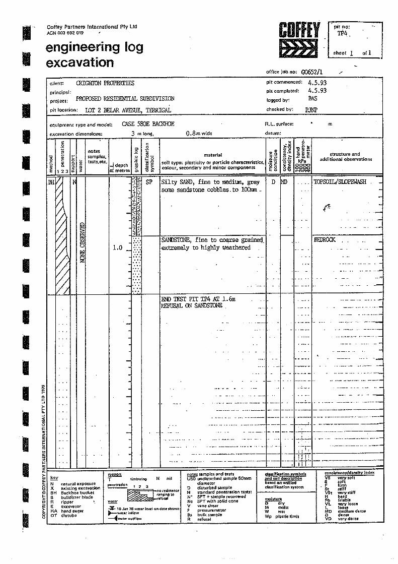
1"IIIIIIIIIIIIII !~\ ~
I i0i=<l;I t€~~'"cc...
I ~~:>-w......
I !I:J
I ~I 8
Coffey Partners International Ply LIdACN 003 692 019
pit no:TP4
engineering logexcavation
sheet 1 of 1
office job no: CXJ5S2/1 -"pit commenced:
pit completed:
logged by:
checked by:
4.5.934.5.93BAS
PM
client: CRIGHION EROPERITESprincipal:
project: ffiOPOSED RESIDENIT..4L SUBDIVISION
pit location: lOT 2 BEL\R AIJE'£,1!E, TERRIGAL
Co\SE 580E BACKHOEeQuipment type and model:
excavation dimensions: 3 m long, O.8mwide
R. L. surface:
datum:
m
c: .g )( 0.~ .'" ~~~'">'0
:Ii notes -'! .,c 0c: c:c-~ .. C:._ ...... structure and" - samples. :.> 0_ material ~o 2> .t: Q. E.. 0 :::0 a:~~
c ~ ... fJkPa additional observations
8- a. .. tests.etc. --! depth :i '!ii-e soil type: plasticity or particle characteristics, "13 ~~.C;;
a. - '0 g cc 0000'" a ~ ;: .!!!> colour, secondary and minor components 0'" 0000E 123 0: metres "" 0 ... Eo u'tl .-NM'¢
BH~
to: :~i; SP Silty SAND,fine to medium, grey D MD lOPSOIL!SIDPEWASH . -::: ~.~; H' ••
'j ~ ;~ sane sandstone cobbles. to lOOmn .. .. , -'j ;3 ~; -
11: -~
-~~
.-. . ._ ...... .... - .. -J:
~
:! :.~ .. • M W _ ... .-- "J, '\. :,..., .: -~
SANDSIONE,fine to cocp:se graine<t · .. BECROO< ... -:/ ~
1.0 _ extremely to highly weathered ... - ~ . - -... .-
~
2 .. ... ... . _......, ·.··.·.w . -,.. . ... .- - .....,... · .'. - _ .... .~-_ .. _-
~
..., .. .. . · - .- .. . - . .- -_.'!":..._ ....,' .. .._- ·... _.-. _ . .. ~.-. -~ ..-END TFSI' PIT TP4 Kr .1.6mREFUS~L ON SANDSTONE
-----_ ..- -_ ...-__ .__ ~w. __ ._._
....._- _ ....- _ ....-
._ -_._-.......... _. --_ _-
.....~.~- _ '-.~
-......... -
...__ .- ...~....~.- "-
...--_..... -' .... -.. ..-_ - -, _. -- -
............. - _ _ _ -.... ·w· •• _
-_. _. _ --._ .. - ----_ -----
- ~:-~--:-:-~~~:~~-~;:~~~~-[S~~~~;~_:-~-
-_ .....- .... ,- ... -'1'- ··1~--1-~·4-~~·1--~=~·=~~=·.~-·--.·=......~~~~.~~-=~~~==.~=-=:~=~-----Hi'- - "-"-.--.-..........
supoort limbtringT N nilclasslficaticmSYmbolsii\d$OITiI8based on uclassification system
.onslstency/d .... ity indexV5 ve!ysolt5 softF firm5t stif!VSt very .tillH hardFb frlablaVi. v.ry 10009L loonMO medium d.llSeP den.eVO ve,V dens.
!!2m samples and testsU50 undisturbed sample 50mm
diametero disturbed sampleN standard peneltotion tests:N' SPT + sample recoveredNc SPT with solid coneV vane shearP pressuremeterBo bulk sampleR refusal
.!5!YN natural exposureX exi sting excavationBH Backhoe buckelB bulldozer bladeR ripper "E excavatorHA hand <lugeraT diatube
~ 123~not!Jisten ..
t.ang5n~ tonh,lsaJ moisture
~yM moistW wetWp pia. lie limit
~.,z.. 10 Jan 78 waitt level on date shown~..,...terjnfJow
~Wiiltrro"'tfIOw
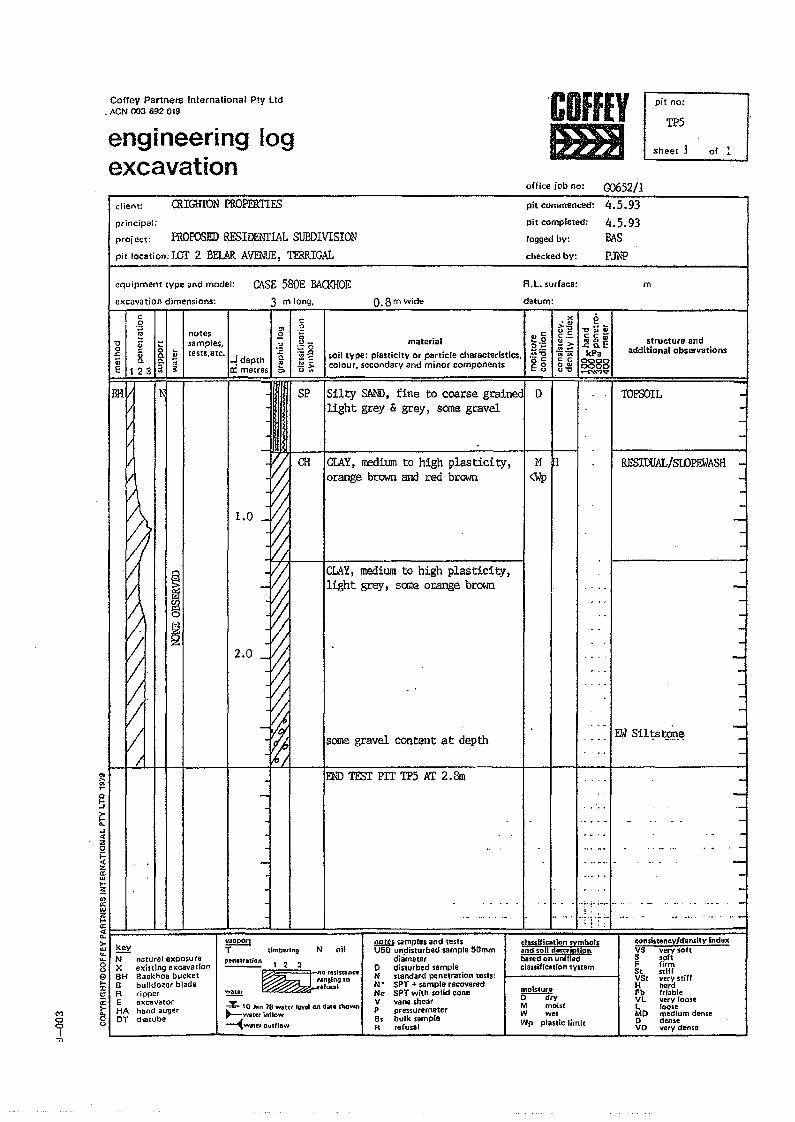
Coffey Partners International Ply LId• ACN 003 69Z 019
engineering logexcavation
.COffEYmJ sheet J
office job no:
pit no;
TP5
00652/1
of ~
client:
principal;
project;
CRIGHION PROPERTIES
ffiOPOSED RESIDENTIAL SUBDIVISIONpit location: rill 2 BEL.<\RAVThliE, TIRRIGAL
pit commenced: 4.5.93pit completed: 4.5.93logged by: BASchecked by: PJ'N"P
ClISE 580E BAQ<HOEequipmem tYpe and model:
ex cava tion dimensions; 3 m long.
CH
a.8m Wide
R.L. surface:
dlltum:
m
c.2
'" .~
'ILnotes Sl :;samples. ~
,,-o -;! ... :.=0.t:: ~ 8- .. [esn.etc. .- .0" ~dePth ~ ::lE~ 12"3 [
:::; ~ .5!>~ Il: metres '" u~
BH N SP
i/
materialsoil type: plasticitY Or particle characteristics,colour. secondary and minor components
.. e:~.g.~]Ell
><:...>.""r;:c_:!!>.~~r;: c0"""
o:> .." ....cc-
2~EkPa
00000000-NM'Ct
structure andadditional observations
Silty SAND, fine to coarse gr:ainedl Dlight grey & grey, some gravel
CLAY,medium to high plasticity,or:ange brown and red brown
CLAY,medium to high plasticity,light grey, SCXileorange brown
some gravel content at depth
M ~<Wp
TOPSOIL
RESlOOAL!SIDPEWASH -~
-
-
-
~Q
!:it....<CZo
~II:w..~'"0:wr:~I I I I! I I I Ia.. I If' =i>- k' I 1 •w cy<L --u. N naturnJ eXPO$ure8 x existing excavation9 BH Backhoe bucket~ B bulldo~er bladeer R ripperC2: E excavator~ HA hand auger8 DT dielUbe
MooI-n
l.0
~!i1§~2
•.:'1":-~-I I J '!;
END TFSl' PIT TP5 AT 2. 8m
• - •••• _ •.••..• _ .- •• 1-- ._ • _.
E~ Sil1;:st.9n~
-
N nil!!!lID samples and testsU50 undisturbed sample SOmm
diametero disturbed sampleN standard penetration tes.s:N' SPT + sample recoveredNc SPi with solid coneV yane shearP pres.uremeterBs bu.le sampleR refusal
~onslst.neY/d.nsitY indexVS yery soltS .oftF firmSt stllfVSt y!tV stiffH hardFb friableVL very looseL looseMD medium denseo denseVO ""rv dense
elassifleatlon symbolsand soU d_criptionblsed on unified~Iassiflcall()n svstem
pen.tulion 1 2 3
~~O"'l ... n<oranging 10
r.fus.al
~ 10 JlIn 18 waltt leyel on date s'hown~wau~r innow--1will!1 Dutflow
-
-
--
iu~par~
,--- tlmb'tlng
':!.!!!! mal$tur.o--d(vM moistW ... \Wp plastic limit
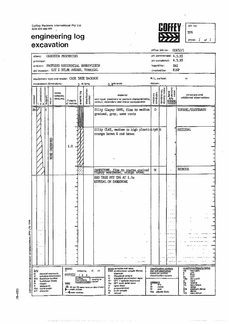
CoHey Partners International Pty LIdACN 003 692 019
engineering logexcavation
pit no:a TP6
sheet of 1
office job no: Go652/1client: OOGHTON PROPERTIESprincipal:
project: PROPOSEDRESIDENTIAL SUBDIVISIONpit location: LOT 2 BELAR AV'E:\1JE, TERRIGAL
pit commenced: 4.5.93pit completed: ".5.93logged by: BASchecked by: P.Th"P
excavation dimensions:
'"...~Q
'"oJ
~..oJo:c5t::o:cza:w...~'"a:wZIi:o:c0-
>-WU.U.0U@
'":I:CJa:\"')
>0-
0 00 uI
en.....
':\ m long,
mN nalural exposureX exiSling excavationBH 8ackhoe bucketB bulldozer bladeR ripperE excavatorHA hand augerDT diatube
Ql
notes I .Qsamples, .~teSl$.etc. . d h ~
...J apt '"ci metres :"
eQuipment type and model: CASE saOE BACKHOEORm wide
R. L. surface: m
material
soil tYpe: plasticity or particle characteristics.colour, secondary and minor companan!s
datum:
",==~o:J"::::
.;:0OC<;0_u
D
"~~t~~Z.c Q. EIIPa
8888-C'lM'd'
structure andadditional observations
.§;:;u_s.,g~Eu~
><'.,>-"u~c.=~?;
ai; "::;C C0"u"
"
TOPSOlL/Sl.Ol?mASH -
LO
Silty Clayey SAND, fine to mediumgrained I grey, seme roots
Silty CLAY, medium to high plastic!ityl'l 18orange brown & red bJ:own
......M
-
-
.
--
iUpportT--- timbering
~ANDSIO~.1 fin~..to coarse. grainedIhgtUy w~tfie1.=, orange brownEND TFS:r PIT TP6AT 1.7mREFUSAL ON SANDSTONE
N nil
ponltralion 1 2 3
~nor~li ... n<.'anglng tort(uJaI~
-z.. 10 J~n 18 waleI' level on d.tl!~shown~WJ\e ...InrJcw~w~,e, oudlow
classification symbofsand soil dDScriptionbased on uOUitdclassification system
!l2l.!l.l samples and teSISUSO undisturbed sample 50mm
dlamelero disturbed sampleN standa,d penetration [esU:N' SPT + sample ,ecoveredNc SPT wilh solid coneV vane shearP preS$utemetorBs bulk sampleR rerunl
moi$loreo--d(vM moistW w.tWp plastic limil
JCl RESIOOAL -
-JC
)
BECRlXK --
... _....... -
consis!ineyld.nsiW indexVS verysof[S softF firm51 S1iffVSt very. stiIfH hardfu t,iabl.VL very loo,el. loonMO medium den,eo dl!nSBvo very dense
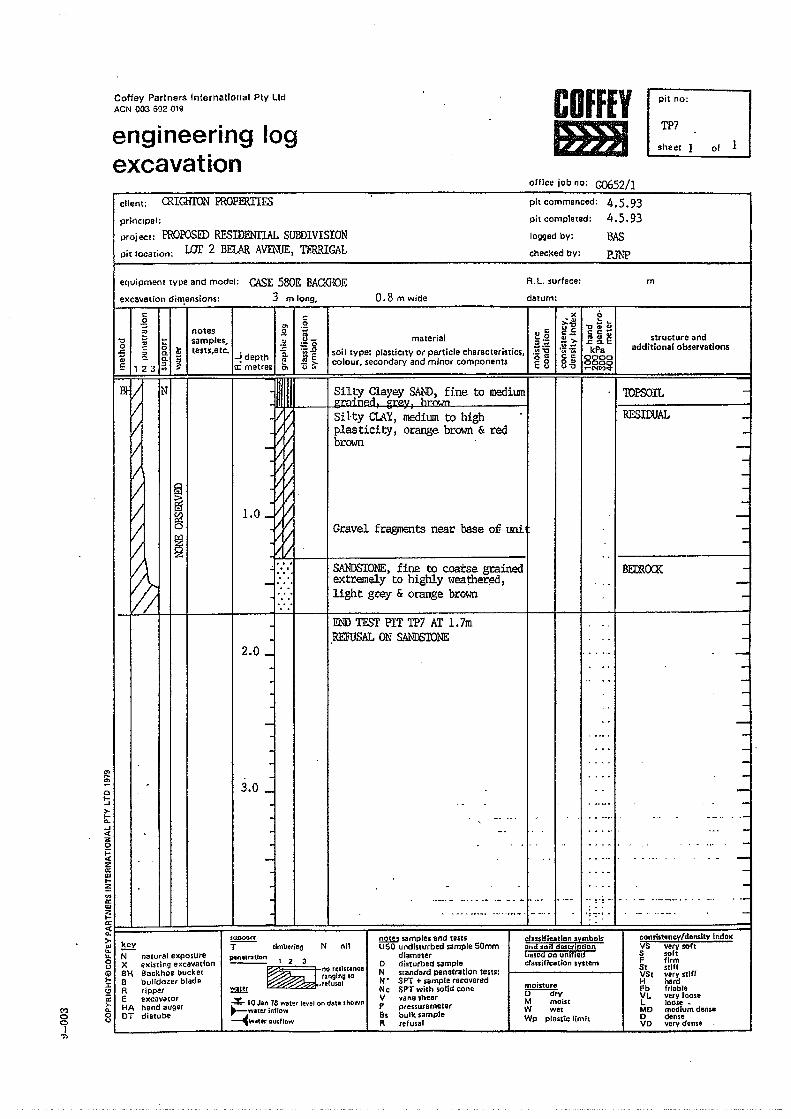
Coffey Partners International Ply LIdACN 003 692 019
engineering logexcavation
COffEYJHBl
pit no;
TP7
01 1sheet
ollice job no: G0652/1client: CRIGHTON PROPERTIESprinc.pal:
proj ect: PROEOSED RFSIDENl1AL SUBDIVISIONpit location: wr 2 BElAR AVTh1JE,TIRRIGA1
pit commenced: 4.5.93pit completed: 4.5.93logged by: BASchecked by: PJ~'P
eqvipment tYpe and model: CASE 580E BACKHOEexcavation dift!.ensions: 3 m long, 0.8 rr. wide
R.L. sudace:
datum:
'"...!!!aI-..J:>-l-n...J«z9~z0;w...~'"a:.wZt-o:~:>-wu....0(J
Iii>...:t:(!l
ii:C'l
>-n.0 00 <>
17>
....::;~ .. ~--J -J _-- ~
... , 9 .
1.0
.g'" .2
51 ~ ~ '-notes £! H_samples. .~ :.:0lests,etc. '-.0
~ 6. g ~ -! depth -a ~E" .!l!>
E 123 a ;:: 0: metres t;. '" '"
~§
~
m
" •• 4
I::.
x 0.:u :: ..>'''0., c °c 'tI ....
C._c: C:"'I structure anc!material :s .g !:>- ~~E..- additionalobseryationssoil type: plasdclty or particle characteristics, .lii:g .~~~kPa
colour, secondary and minor components @ g cc 00000" 00000'0 ......NMo;t
.~ilh1r.l",uoU!<;:Al\.Tf'I. fine to mediumm '1 TOPSOIL -• m ... -rL c:r",y I brown
Silty CLAY, medium to high .,I I
I RESIDUAL -plasticitY, orange brown & red -brown --
----
G.cavel fragments near base of unii I I --SANDSTONE,fine to coarse grained I I I
BFXR(XX -extremely to highly lv~!:her~d, · . -light grey & orange brown I -END TFSl' PIT TP7 Kf 1.7m
I I I -.REFUSAL ON S.I>,NDSTONE -
.... -. -· , -·. --
-·. -
, .... -. .. -
. _.- -
.... -.. -". ,. ....... -
__ .0.<0 ...... ... _._ .... -
- . ... ." ... -.. ..- .. ' -....... ....... . - -... - -
-I I I..·· -.. N.. _ ....... _. ___ .... _•.•. __ ..•.• _. _ .. _ .0_._ ..0,_ ... ..-
--_ ...._. - ............. _.-. . ,~.;.:. ..- '" .._ .... -
-2.0 _
-
3.0 _
.
.
5UD$)CJ.ff
T--- dmb,ringl!!YN natural exposureX exi'ting excavation81-1 Backhoe bucketB bulldo«' bladeR rippere exeavatorHA hand augerDT dietube
N nilol... ifleatian symbolsand $oil dlltSl:tlptfonbased on onltledcra$SLricudon systf:m
consistency/density IndexVS very sohS sohF firm5t stiffVSt very stWH hardFb frlobleV l. ve,y 100"L loo,e •MO modium denseo denseVD very don,e
!!!2W SlImpI., and testsUSO undisturbed sample 50mm
diameterD Disturbed ,ampleN standard penetration tests:III' SPT + sample recoveredN c SPT with ",lid coneV vane sheafP ptessutemClera, bulk sampleR ,efus.1
~
~ 123~nO"'ill.nc.
ta~glng '0nfuUlI
4\0 Jan 78 waler level on dbtl showl"l~'WV .. t~t inflOw~wner DUlflow
~o dryM moist:W wetWI' plastic limit
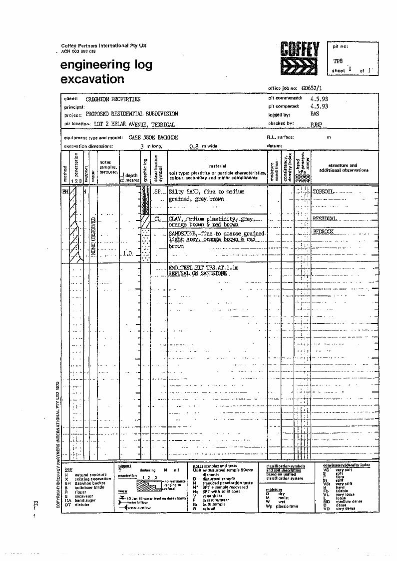
Coffey Partners International Pty LtdACN 003 692 019
engineering logexcavation
CDfffYJmJ
oHice job no: G0652/l
pit no:
TP8sheet 1 of 1
client: CRIGHION PROPERTIES
(")C"'c
~
principal:
proiect: ffiorosrn RESIDENTIAL SUBDIVISIONpit location: wr 2 BElAR AVENUE, TERRIGAL
pit commenced:
pit completed:
lOGged by;
chocked by:
4.5.934.5.93BAS
PJNP
excavation dimensions:
equipment type end model: CASE 580E BAa<HOE0.8 m wid.
l!!~ ...
c.g~..c~
'"notes .!l~I Isamples. .~Cl. Iii tests,etc . .J -aQ. ~ depth IV
a ~ cr metres &
'tlo£E 1123
3 m long,
R. L. surface:
~lum:
2"'<ises:",~ 8. EkPe
~
m
structure andadditiomll observations
,- . 1;3•••.;::;.. ". ,.. ~
...:~;:'. ~-I:·..:::·'~:·I~l,.o.I':........ . ........ 'I.
•••• I.
o~E..J
:Ii9~z..:w...~I ..
: ..
In0:w
~r-~l=>w......89....:cCl
~8
,....!.;...
., . _CL..__.CLAY:•..~ilUR plas tici ty; ..grey.,._. •• _.,.... -I' -~.~·tRE.SIOOAL .. - .... -_._ .._ .... =jorange brown & red brown ., __. __.__ ..:..:...:..:... _
:::~: . ". SANDSTONE,_.fine. to coarse grained. -. ,- ..... -: _c~. j}r;m~:~L...... . --... -_oo.. ' ~~~~ gr~YJ--Q~~~. ~~~=~~~d-=_..-.t~..:J~~t=1~:'[.~·:.~~~:~~._.'~.'
-..'IENILTE'Sl' .. EIT TPB. Kr .1.lm.. _.. F!WS&.9.ij .S@D$lPmt
.. .' .~._ .. _ .. '5:a: "t-;- --._-- -_ .•.. --_. -..: ._~=~~fi'~'~~=~~~...:~...too .. ~: ~ _ .. __ ..... _ __ . .... ---
<:.2
~o·S~~>Ow
material10il type: plasticity or particle characteristics.colour. secondary and minor components
,SP---ISiJ,.ty SAND, fine to medilJffi... grained, grey. br~ffi
-
. ;
~
.....,.
-
-
-
. 'I.:.: .:. -1.lUPSOIL-- ---- ... -._...~.:..;.;.... _- -~_ ....
.-.~I--"-'-"""-" - _._.-
.. c:;..0:J ";;
.~~or::E8
l(
~is:._f!:.-.~.~c <:0"V'l;l
..I ...'
• ··h· _ 'I.'_~ '~-I ...... _._
, .=·.~J~T~~:~-=~--=~-=·~-~-~~-~,"~:''.=
lIilcl... ln.-don symbolsand SOil descriptionbasld on un;llt<ll;lnsification Iystfm
keyN natural exposureX existing excavationBH Backhoe bucketB bulldozer bladeR rippere excavnOfHA hand augerOT diatube
~ 1imb~'11\gT
p*n.u-.dCln 1 2 3 no ,....In.nee--~ngln;IQ
.tul.tl
..... ~ I" I. .... "~ .••••• -
.~. = [~:J~.~~1·[_~.=~'_:..~~_..
'~:J~~J~~.:~f.~._-.-'~-'-~~.>~~~--'-~_.~~'.=:.: ..~ ..... --, -- - - .. -
-.:::~=~~:-_:::~~~~_~.mr;:~;=:~~;:;. .U"l1.~ --.... -... _. .. ...... _
~-ri------_~:.:~.~_.______-1--·'-I--I-H' -"'-"----- I I
-
~
--_... ---
.. ..._ _- ._ -- _ ..- -_. -_ _.__ ..-- .._---
..
N!!2W samples and testsU50 undisturbed 5&mple 50mm
diametero dillurbed sampteN sland3rd penetration tosts'N' SPT + sample recoveredNe SPTwhh Solid coneV vane shoarP ptonur.mllerBs bulk ssmpl.R rerusal
....::a 10 Jln 18 Ytlittt Jewl on <fa' •• hown~wturlnnow~wa"routfJCh't
rnolltur.o dryM molnW wtlWp ptlStic Umit
<:omist.ncy/d.Mtlv indo.VS VIrvsoitS lollF linnSt stillVSI vIrv,tillH hardFb frl.bleVL verv 100..L looseMO medium dIn ..o den ..VO voryden ..
-
,-
--
-_ _~-
-
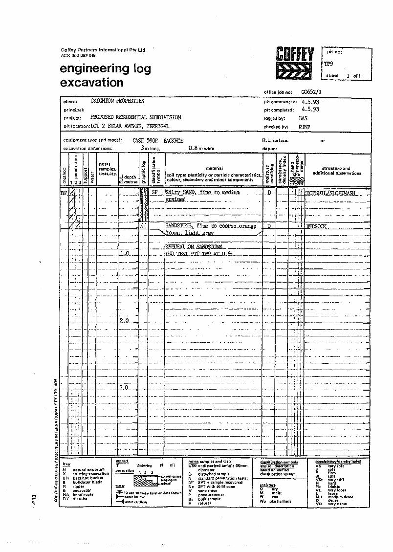
Coffey Partners lnternatfonal Ply LIdACN 003 692 019 CDfffY
fmJpit no:'
TP9
sheet 1 of 1en'gineering logexcavation
office job no: G0652/14.5.934.5.93
BAS
P1NP
CRIGHIDN PROPffiTIESclient:
principal:
project:
pit commenced:
pit completed:
logged by:
checked by:
m
'"~c::l~~0-...J.;:Z0i=.;:zc:w...~'"a:wZI-a:.;:...>w...u.0u11>I-:::CJc:
M>"-
C" 8<;
PROPOSED RESIDENITAL SUBDIVISIONpit location: LOT 2 BEI.AR AlfEI\ljE, TERRIGAL
CASE saGE EAa<HOE3m long, 0.8 m wldt
equipment type and model:
excavation dimension.;
R.L. surface:
datum:c.g C
ell 0~IL notes .Q lL~ ~ 8. ~ samples, .2 ;0 moO." 1'.8tests,atc. . .z:;
~~ soil type: plasticity or particle characteristics. .~ '6~ c.o.~ ..J depth 0.
E123a~ Iimetre... .!!>- colour. seconderv and minor components ~ 8l;. .....
>< 0• 0 .. II~~~~t~'>'~&E~.= kPaCC:~
8~ ~l;j!
structure andadditionlll observations
....- ...._- "§f'_'I~~J_ty~~, .1.:l'Q~...to, 1l\€di1J1l!__, ~"!1~..9.,'__. . _ ..I_"~!:~. oJ.~5
: I
-",:-!.~.-r'J- ---_. ~ -". ---......-.-
,: j
"
~ llml>l,iogT
P4nwa.ian 1 2 3 no retlltlnCl- --- --~,.nllnD'O
r.fuJ81
llll.IU >ample. and te stsUSO undisturbed sample 50mm
diametero dlstu,bed lampl.N standard penet,at;on teSl1'N' SPT + sample recoveredNc SPT with $olid coneV vane shearP pressure meterBs bulk sempleR refusel
N nil el... iH""U"" svmbols."" ..,11 a......,,:!Ilan.",.ad on unlllcl.ssiflcation .ysum
~N naturel exposu,eX existing excavationBH Backhoe bucketB bulldol.' bladeR ripperE excavatO'HA hand auge,OT dlatube
molstufto dryM molnW mtWp prattle limit
~~ 10 Jln 18 wattt tl'Ytl on (fat •• hown~~tlflnflQw~wat ... outlEow
C:OllSktan~'d.",1tY indaxVS--v.rY.i>TtS loh" firm5t iliffVSt vary stiffH h"dFb frl.blaVL VOfV 10011l. 100••MD medium den ..Odin",vo "'''-v denle
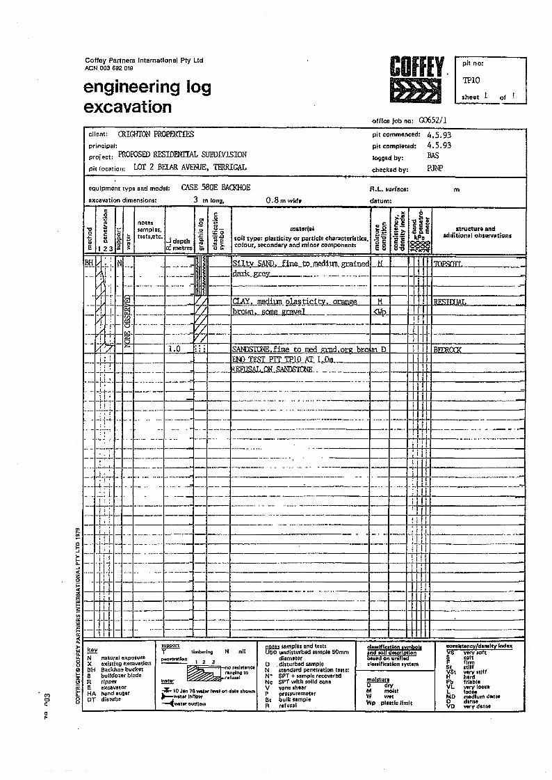
G\to.~Q
!:i~....e....0:'20;:0:'2ffi~'"'"UJ'2....0::::~u.u.80....::I:CJa:
M~
0Co
<:0u
c:,..
Coffey Partners International Ply LtdACN 003 692 019 COffIY.
&lJpit no:
TPlOengineering logexcavation
.hllet 1
office lob no: rY.'J652/1client: CRIGHTON PROPERTIES 4.5.93
4.5.93BAS
P.Th"P
pit commenced:
pit completed:
logged by:
checked by:
principal:proj ect: PROPOSED RESIDENTIAL SUBDIVISIONpit location: LOT 2 BElAR AVEr.1JE, TERRIGAL
O\SE 580E BAa<HOEequipment type and model:
excavation dimensions: O.8mwid.R.L. sutface:
datum:m
3 m Ion!!.
c.2;0~I ~ ~Q C 0 L-
-5 8. ~ ~~ ~~Jal istructure and
additionel observations
AV. mMlillm nll'l!=:rif'itv. nnona.,. I M. ~--~~-~--... --___ .. _ . -...~ __....L
NDSIONE.fine to med m:nd.or.e bro~ D
---'=~~~~_...----._.~-1j'- e~;:-;u':----------t--H-+-++t------• i-L.i. - .•- - .. --- ..- _._.- _. --- --- -.-- - ..-------- .. -- . ··I-·-I--I-++-I+t-I----·, .~Jtr::=~===--- -1---- ."-":~:'."".-.--- -..-
.J"':.;•• " .. __ . ._ _ •._ ..• __ , _. : I II~~~'F-~'"-:~..-.._~~~~~~:~.-:.~:~~~:.~:~.=====~~-.~--.~~~-.....=~=--..--. ....~~.~=~1IE=--~-~:.~~.:.~~.~.--~~~=, ; I q~=-~:T=~~=~:~:_~.~=_._==_~=~~'.:_.......'. ...-:-=___ I_+·..;·-li!-!i+ _
....--'-: _.-- -_.-.._.- . _....._.._-_ --- -----....- -._.._-_ ...--·t----1I-HrH-l----------.__ .~:_. _ .._ _ . .__w_.__. .___..:.:.i . . _ _~_.... .._.._.. ._ .._. ._..._.. __ ...
·!f~~~-~:i~====~-~~~-~~=~~;-:=-=== - -" I-i"r-~'-..- -.._-- ._- ------ -- -- .lIT =~=.~=~....~:==-~-==-~-==.._- -------.-----.-,II'~Gf- :~ :~-.--=.~-~..~..---'=~===~---·-----==---=.-=.=---·------I-_t-_t+I_t-*-_.__. ._..__.-~==~=I---+-_.--1-+++++---~ __let .-_........--'-" ---...-..-. -i-I- ... - ..-- _... _- --- ---" -- ..-------------.I--l--+-H-t+t-----'--------J
._ •.~L.~_ ..... .-- _ .. _.-. -- -_ ..--i I
_~nJ, ....+.oy..f.o.J. .. ~.,.I.IllL. ~LJ1J .UN •..."A['IIIl..." ill JNtt. I ITI I
--
N nilel ... lflir;1lon symbols.na so esal~rJnbUidoQunillclanitication IVl1.rn
....... lot... ey/d.ns!ty Ind."VS vt<Y 10ftS .oftF firmSt I1lffVS1 very nllfH hordFb f,lobl.VL -v looseL loo.eMO mtdlum don~Odin ..VO _yd.n"
!!QW samples end lest.U50 undisturbed sample 50mm
diameterD . disturbed <ampleN siandard penetration telH:N" 8PT + sample recoveredNc 8PT with solid coneV v~ne shearP Pfeuu remeterBs bulk sampleR refusal
F 11mborlng
ponw-atlon 1 2 3 "" r .. lr1One.. ---~ . ,..nolnglo
rlfuul
mN nalurel ."pOSUt.X ox ilting excavationBH a.ekho. bucket8 bulldo~er bl.deR ripperE .KeaVlltOrHA hend augerDT di.,ube
!!!2im!IIo dryM mobtW wetWp plntle lImil
~~ 10Jln 78_1., r.,..1 "" do,o .hown~WOI",'nfl.w~Wlt.t outfl~
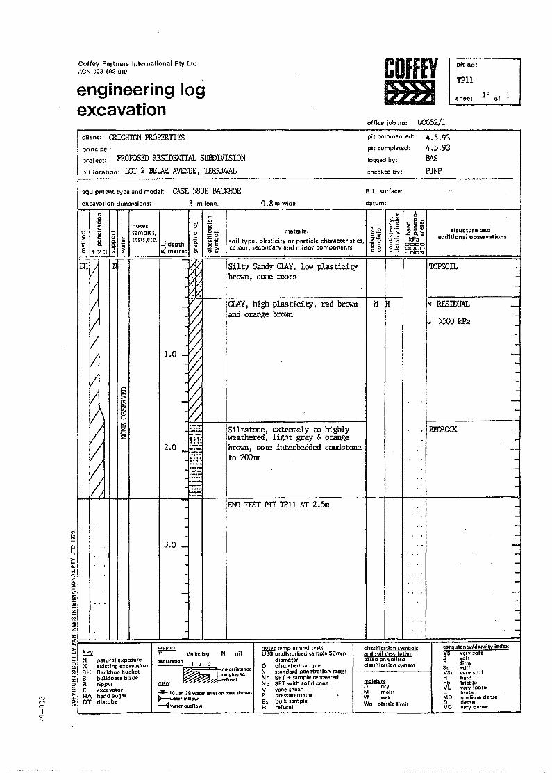
Cofley Partners Inlernational Ply LId"eN 003 692 019
engineering logexcavation
COffEYtmI
pi! no:
TPllsheet ]' of 1
office job no: G0652/1
'"....~
~
principal:FRoroSED RESIDEi\'ITAL SUBDIVISION
pit commenced:
pit completed:
logged by:
checked by:
project:
pit location: IDT 2 BELAR AVTh'UE, TERRIGAL
4.5.934.5.93BASPJNP
client: QUGHIDN PROPERTIES
equipment type and model: CASE 58DE BACl<HOEel<cavation dimensions: 3 m long.
R.L. surface:
0.8m wicie datum:
m
o~>-l-e.-'<Czo~zc:UI
~...c:wZI-~F=~==~:::!:=:!:::==T============!:::===;========::======;=~=::=~=:::!===::;r===:::::::;=':::::~~~~::::::=11:; key.... -II. N8 XI'J) BH!i; Bt.? R;;:Eit HA8 OT
,.,o'=Ia~.
g t:.;;
'" .2~ notes .2 '"" ;;() samples. u u-
0 c: tests,etc, :c 0;:0
t OJ C. 0> .- .D
a. Q. j -!depth <l. :::EE 12 J ;;: 0: metres C .!)!>-
C'> u"
1.0
~!i1~~2
2.0
~
-3.0 -~
.----. ,
sPJpponT--- limbering
natural exposureexist1nn excavationBackhoe bucketbulldozer braderipperexcavatorhand augerdi3tube
Silty Sandy Gf.AY,low plasticitybrown, some roots
... c3:;.~na cE 8
(,
'C~~cc:~"' ......c: c. EkPa
00000000_NMq'
structure andadditional obseryatlons
-
-
-
-
consisteney/densily incl,'"VS very softS softF firm$t .l;lfliSt very stillH herdFb Iri.bleVL very 100leI. looseMO medium d,nS8o c1enseV() very dense-
"......""c:r:._=~'Vi'Mc:c:8~
M lH
'IOPSOIL
l( RESIDUAL
l( >500 kPa
BErero<
dauification symbols;and $oil descriptionba,ed on \tnlfledclassification Ivotem
materialsoil type: plasticity or particle characteristics,COlOur,secondary and minor componenlS
CLAY,high plasticity, red brownand orange brown
Siltstone, extremely to highlyweaJ:hered, light grey & orangebrown, some interbedded sandstoneto 200rrm
00 TESTPIT TPH AT 2.5m
N nil
moistureo--diyM molS1W wetWp plastic limit
!l!!W samples and test,usa undisturbed .ample 50mm
diametero disturbed .ampleN oton(/ard penetration tests:N' SPT + sample recoveredNc SPT with solid coneV vane ,hearP pressuremetarB. bulk sampleR terusal
'!!!!!!
pell •• tAtion 1 2 3 olt',d11IllCC. --_····~~.nginaIO
fe'u",.
4 10 Jan 78 wlt!!'r level Of' date shown~wat~,nnGW~water outflow
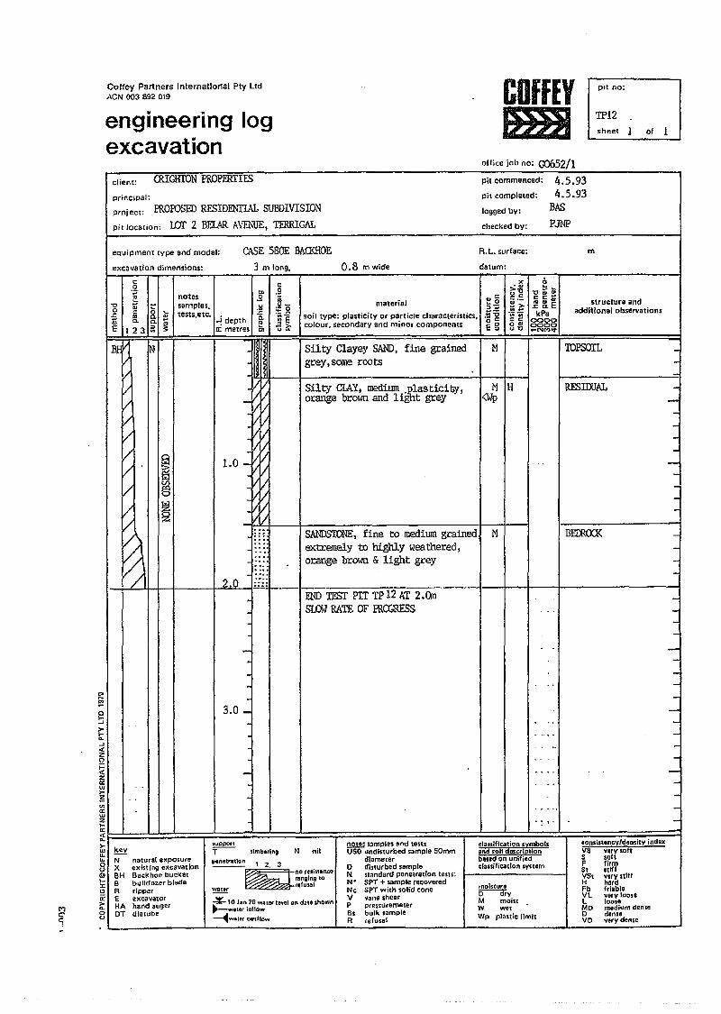
CoHev Partners Inlemaliortsl Ply LIdACN 003 692 019
engineering logexcavation
COFfEYmJ
office job no: G0652/1
pIt no;
TP12sheet of 1
client:
principal:
CRICHTON PROPERTIES
PROPOSED RfSIDENfL.xL SUBDIVISIONproj ect:
pit location: LOl' 2 BELAR A\'El\1iE, TERRIGAL
ph commenced:
pit completed:
logged llYl
checked by:
4.5.934.5.93
BASP3NP
meQuipment type and model:
excavation dimensions:
CASE S80E BACKHOE3 m long. 0.8 m wide
R. L. surface:
datum:
I
~&:i~~~
/
notessamples,tests,etc.
material
soil type: plasticity or particle characteristics,colour, secondary and minor components
'".!2 .. "~.g.~:gEg
M
<.:>--0 ....c:c:~........<: a. EkPa
00000000_NM~
structure 11011additional observations
2.0
Silty Clayey SAND,fine grainedgrey, some roots
Silty CIAY, medium .plasticity,orange brown and ligbt grey
M IH<Wp
x..."'"0"c:<:.-
~~·.:iUi"c:0'"ul:l
...M........
...J ....
'"~aI--'>-..........I<CZ0;::<CZe.::wI-~'"0:wZ,..0:<C..>-....u.u.S(9)l-X~0:
C') ~co 0
'1 u
~N natural exposureX exi,ting excavationBH aackhoe bucketB bulldozer bladeR ripperE excavatorHA hand augerDT dlatube
SANDSTONE, fine to mediumgrainedextremely to highly weathered,orange brown & light grey
.;_.-. oo-i'Fsr PIT TP 12 AT 2.On
Sf..(M RATE OF ffiCGRESS
-
3.0 _
---
N nil
~ 12.3~nO"'ln.n<e
ranging to"rUgl
support-T-- timbering
!!!!!!41o Jllr\ 78 water le're:l on do •• show,",~Wilttr inflow~w.tt1'r oUlflow
!!.21!l sample, and lestsUSO undisturbed sample !iOmm
di.matero dbwrbed sampleN sl.ndard penetrOlion te't':N' 51'T + sample feCoveredNc SPi with solid coneV YanG shearP pre$Sureme:terBs bulk ,ampleR refusal
•• I'
clcssiflc:ation ~Yh'lbolsand soil descriptionbased on uoiliedclassificatfon system
!!!2!lli!!:!o dryM moist.W welWp plastic limit
TOPSOIL _
RESIOOA1 -
BErn.<Xl< -
-
-
1
conslst.ncvldonsitv indexVS Very,oftS softF firm5t stiffVSt v;ryslllfH hardFb friableVL very looseL looseMO meditJm demoo denseVO very dense
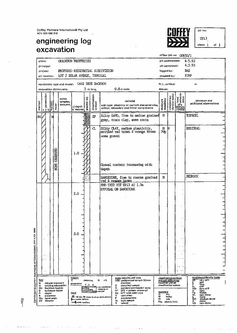
Coffey Partners International pty LIdACN 003 692 019
engineering logexcavation
COffEYmlI
office job no: GJ652/1
pi! no:
TP13sheet 1 of 1
client: ClUGHION 'PROFERTIESprincipal:
project: PRoroSED RESIDEl.\TIAL SUBDIVISIONpit location; LOT 2 BWR AVThlJE, TERRIGAL
m
pit commenced: 4.5.93pit completed: 4.5.93logged by: BASchacked by: PM
materialsoil tYpe: plasticity or particle characteristics.colour, secondary and minor components
a.8m wide
R. L. su.face:
datum:
M
<.'>::.~"0",'"<::c:~.... '"..c a. EkPa
00000000
._NMV
Silty ClAY,medium plasticity,mottled red brown & orange brownsome gravel
!l.QID samples and testsUSO undisturbed sample 50mm
diametero disturbed sampleN standard penetration lests:N' 8FT + sample recoveredNc 8FT wilh solid coneV vans shearP ple.nuterneterBs bulk sampleA refusal
equipment type and model: CASE 580E BAOOlOEexcal/ation dimensions;
'"~g
"'U~I....o c: 0 ......r:. QJ C. iIU.... Q.c.-E 123 511 ~
IN
~~
~
3 mlol19,
.2
.~o~~"'-- >-01 u· ...
1.0
-2.0 _
-
-3.0 _
-
--
~uppon.,=--- tlmbe-ring
!!!!!!
SP Silty SAND,fine to medium grainedl Mgrey I trace clay, someroots
N nilptIn.ttatiOR 1 2 3
E=nOl!'i".nceringing 10refuwl
",'"3:~~~ -ge8
M IH>Wp
".">.""_C.:2>-'"~.~.;;;Sau~
classiltcation symbolsand $011 dtscriptlonbased on unifiedcl8ssifiCo1tion sys1em
molstur.o dryM mobtW we.Wp phntic limit
· • Jnotes 3samples, .\1
oo",.••J~~;:,lilllJ::::;
Gravel content increasing withdepth
SANDSIDNE, fine to coarse grainedred & orange brown _ I I I I IEND TFSl' PIT TP13 AT 1.7m
.,REFUSAL ON SANDSIONE
oo¥- 10 Jln 78 WlIIler le".:1on dau shown~water Inflow~W&le(OudIDIo'I
structure andadditional observations
TOPSOIL -
en....~Qf-...>-f-a....l«2:0;:.
~I I ..~~0>a:u.t
~. . ..0:c(a.>- ~u.tU.u. N nalural exposure0 X ext$ting excavationuEil BH Backhoe bucket~ 8 bulldozer blade:I:CJ R rippera: E excavator
M>- HA hand augern.
e:- o OT dlatubec u1
RESIDJAL -
.BElROCl< --
conslstoney/density indexlis very softS ,oftF firmSt sliffVSI very.tiffH hardFb friableVL vety 10050L looseMO medium den.eo den,.VO very den ••
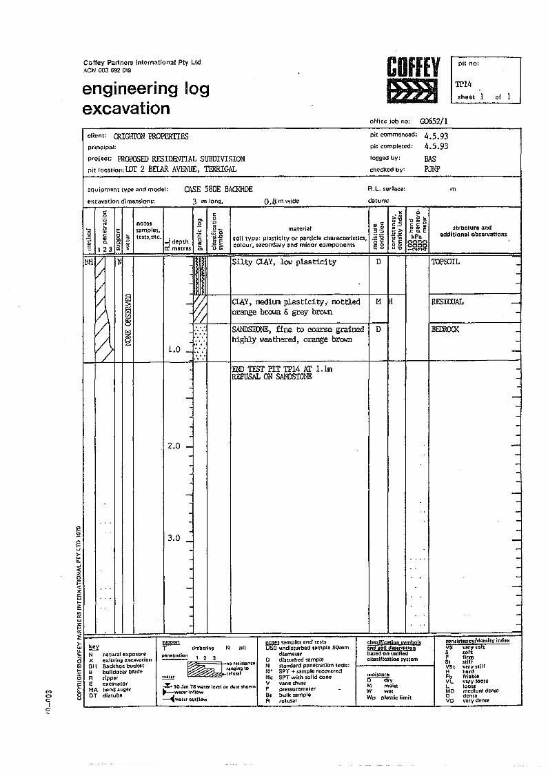
Coffey Partners International Ply LId."eN 003 692 019
engineering logexcavation
COffEY1m!
pit no:
TP14sheet 1 of 1
office job no: G0652/1client: auGHlTh~ PROPERITFSprincipal:
project: PROPOSED RESIDENITAL SUBDIVISIONpit locatioll: l.DT 2 BElAR AVE1\l[JE,TFRRIGAL
m
pit commenced: 4.5.93pit completed: 4.5.93logged by: BASchecked by: PJNP
0.8m wide
R. L. surface:
datum:
D
equipment type and model:
excavation dimensions:
CASE 580E BACKHOE3 m long,
'"...~c...oJ
>-..."-...<CZ0i=<:z'"'"...~'"c::'"~~"->-UJU.U.0uQ...:I:2
M~...
0 0c '"I~
c:aof2 Qj ~...c: o ...
'" c. "E a. 0; -
123 a ~N
Q
ffi§
~
keyN naturat exposureX exi'ting excavation8H Backhoe bucke,B bulldozer bladefl rippere excavatorHA hand augerOT diatub.
..,
F1.0 :::..,. ,
--.....,----
2.0 ---··-·--·3.0 _
-------
I materialnp: llJasticilY or particle characlerislics,
!condary and minor components
Ie"C~o3:::'5 -g
. E 3
I Ir;~c.:e>.. ~.~.~c c0"u"O
structure andadditional observations
Silty ClAY,low plasticity
ClAY, medium plasticityf IOOttledorange brown & grey brown
. M H
SANDSroNE) fine to coarse grainedhighly weathered, orange brown
END TESI' PIT TP14 Kr 1. 1mREFUSAL ON SANDSTONE
N nil
~ 123~n.r!lill.n ••
ranging tDr~luAI
SUPDOltT--
~
·timbering
~ 10 Jan 18 wlter lell'el on dille shOwn"......-:wlt.r ~nfJ()w~wattr ovcfto .....
---r I I I
------------------------------------
classificatiol1 symbolsDna soU des:cr~ptionbased on unilledclo.. ifleotion sysum
!lllW samples and testsU50 undislurbetf sample 50mm
diametero disturbed sampleN standard penetration leSIS:N' SPT + sample recoveredNc SPT with solid coneV vane shearP pressuremscer5s bulk ,ampleA refusal
moistureo--cTryM moiJtW wetWp planic limit
D
TOPSOIL
RESIOOAL
BEIROCK
cons:istency/domil'{ indtxVS vory solt5 soh~ firm5t stiffVSt veryslillH 11.rdFb friableVL very looseL looseMO medium denseo dens.V 0 very dense
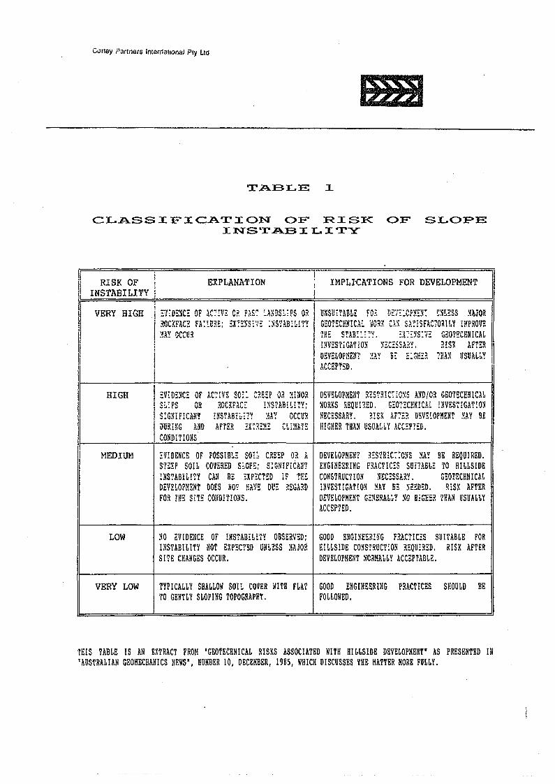
C"ney ?artners intemallooal Ply LId
&l1
TABLE 1
CLASSIFICATION OF RISK OF SLOPEINSTABILITY
[, • !
II RISK OF EXPLANATION ; IMPLICATIONS FOR DEVELOPMENT Ijl INSTABI LITY ! i
,--, i I'_." ~. ~ lr~'1 ~ (I" .,~~ • 'n~"c~ (1:;1 I ~ 1'1\ ~ ,,~ r.""-·"CV··· I"I~~~ •I VERY HIGH :'1,D:.~C::. OF .."'.,~:. \/., :t.w; :.>.L",~,,,,, \I .. I UlUl,ABL:. ~O:. :J~i:_ ...... ~~. .L::.wu :iAJOR:;InC'lrA1"" I1lTf·~~. ·X,,\~,·~·,,- '''~~lB'' lav I G"Q"I11'Illo'1C" ',''''''1 ".,' "~~l~F,r"\ORIIY illpRO"" .I ,.V;,\ ... :. 'lI,cV .. _, :, ::,'w:t: ..'",' .. ;;;':'1 ::.:~"''':1. ;\~ ~\j:\:\ ",~,I ~, ••• w r.w, " '0. 1:1 II
I '/3V ('['''Il';) ·~H;; <:'l'1B·' ~"\v ;'I"\;"~''':' I';lO~I1"HNIC'L........ ~\,,\.. .\ i. 1_ "'." .. ..;;...... _~\ .. _.{v .. f... u .... _\,.t n
I I 1!1"11~r.I·I'A'i' jOlT \';;,r:,;:.<:, jV :l IS') 'FH'R II I l;l~ .. ..,LJ." .... 1 .fo.ll,_ .. vr. .•. I ;'\. t\ l\ • ...,
I • \e'l~ M'"" ~A~V ':" ~.,..,~:) ,:". I~:VII ! ~~!~~~~~lIN...... E. ..••lL. ,HA~ UuUAL. II ~(;'·1o·r"·~1)
I I . ""......
HIGH :nD~YC: OF Ac:m so:~ C~EEPO~ :mlOR O~11ULOPMI1NT R;;'~IllR·r"(lX~ AsniO~ G"OTI1Cl!!lII'Al I.... Lyl .~u:,!I.",v." '~(" ::. ~ .. "" III
S~:PS OR ~ocm.c~ I~snBi~r~Y; I.~ORKS REQUIRED. G~072CHNm.l ~NVEmGAnONS~GNIFICA!lT lNSTABE'i?Y :m OCCUR ~~C:lS~ARv ~T~K 'I''''-j n];"~lnpMEN'l' 'IAv !IE I
II,r, ... \<i.1 .... I .. v.. t.. ... :..~ ~ 'f ~ ..v.. • .•••
I ~URIKG AND Am~ :X~~E~~CtI~A!S H!GHER THAN USUA~~Y ACC:P~ED.I '
I I CONDITlONSI .
MEDIUM I ~V!DENCE OF FOSSIB~:: SOl~ CRE~P OR A DEVELOPMENT ~~S1R!C::O~S Y:AY BE REQUIRED.snEP SOIL covmD ECPE; s:mmICANT ENGINEERING P:lACTIC:S SUm.BL~ TO HiLLSIDE I
1 ;NSTABHITY CAN BE ;XP?:CTED IFrE CONSTRUCTION ~EC:SSA~Y. GEOTECHNICAL~ ~f ~~, ~ • ~ C'\9~ 1;'~ INVESTIGATION Y:AY 55 ~2EDED. RISK AFTER. DeL.OP',uN. DOwS NO: .. 1'.1.. DU~ .•"GBD
I f FOR THE SITE CONDITIONS. DeVELOPMENT GE~SRAL~Y so HIGE~~ THAN USUALLY
I ACC~mD.
LOW ~O ZVIOENCE OF !NS?ABI~IfY OBSERVED; GOOD BNGmmNG m,mc::s SUIrABLE FORINSTABILITY NOT EXPECrSD UNLZSS MAJO~ HmSIDE CO~ST~UCTION ~EQU!RED. RISK AFTERSITE CHANGES OCCUR. DEVELOPMENT ~ORMALLY ACC~PTABLl.
VERY LOW TYPICALLY SHALLOW SOE. COVER WlTH FLAT GOOD ENGINEERING PRACTIC~S SHOULD BETO GENTLY SLOPING TOPOGRAPHY. FOLLOWED.
THIS TABLE IS AN EXTRACT FROM 'GEOTECHNICAL RISKS ASSOCIATED WITH HILLSIDE DEVELOPMENT" AS PRESENTED IN1AUSTRAL IAN GEOHECHANICS NEWS', NUMBER 10, DECEMBER, 1985, WHICH DISCUSSES THE MATTER MORE FULLY,
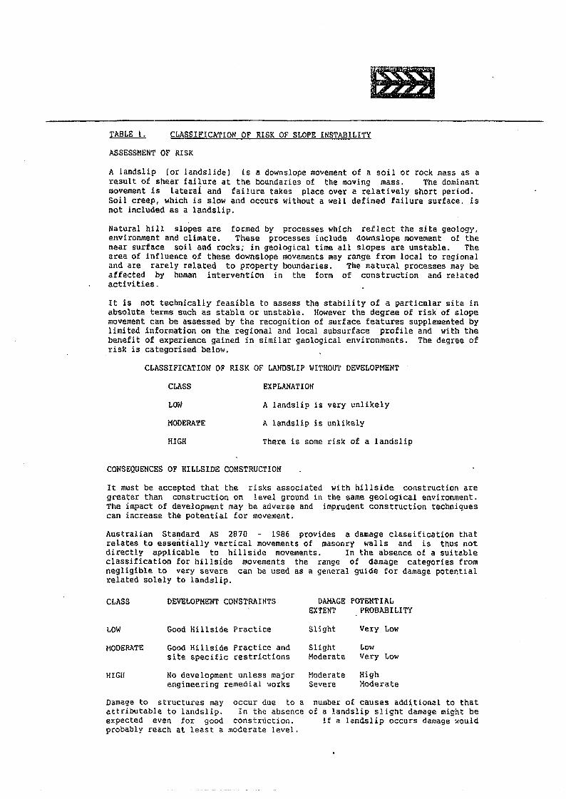
IBTABLE l. CLASSIFICATION OF RISK OF SLOPE INSTABILITYASSESSMENT OF RISKA landslip (or landslide) is a downslope movement of a sailor rock mass as aresult of shear failure at the boundaries of the mOVing mass. The dominantmovement is laterai and failure takes place over a relatively short period.Soil creep, which is slow and occurs without a well defined failure surface. isnot included as a landslip.Natural hill slopes are formed by processes which reflect the site geology.environment and climate. These processes include downslope movement of thenear surface soil and rocks; in geological time all slopes are unstable. Thearea of influence of these downslope movements may range from local to regionaland are rarely related to property boundaries. The natural processes may beaffected by human intervention in the form of construction and relatedactivities.It is not technically feasible to assess the stability of a particular site inabsolute terms such as stable or unstable. However the degree of risk of slopemovement can be assessed by the recognition of surface features supplemented bylimited information on the regional and local subsurface profile and with thebenefit of experience gained in similar geological environments. The degree ofrisk is categorised below.
CLASSIFICATION OF RISK OF LANDSLIP WITHOUT DEVELOPMENTCLASS EXPLANATIONLOW A landslip is very unlikelyMODERATE A landslip is unlikelyHIGH There is some risk of a landslip
CONSEQUENCES OF HILLSIDE CONSTRUCTIONIt must be accepted that the risks associated with hillside construction aregreater than construction on level ground in the same geological environment.The impact of development may be adverse and imprudent construction techniquescan increase the potential for movement.Australian Standard AS 2870 - 1986 provides a damage classification thatrelates to essentially vertical movements of masonry walls and is thus notdirectly applicable to hillside movements. In the absence of a suitableclassification for hillside movements the range of damage categories fromnegligible to very severe can be used as a general guide for damage potentialrelated solely to landslip.
CLASS DEVELOPMENT CONSTRAINTS DAMAGE POTENTIALEXTENT PROBABILITY
LOW Good Hillside Practice Slight Very LowMODERATE Good Hillside Practice and Slight Low
site specific restrictions Moderate Very LowHIGH Mo development unless major Moderate. High
engineering remedial works Severe l10derateDamage to structures mayattributable to landslip.expected even for goodprobably reach at least a
occur due to aIn the absence
construction.mode!:ate level.
number of causes additional to thatof a landslip slight damage might be
if a landslip occurs damage ~ould
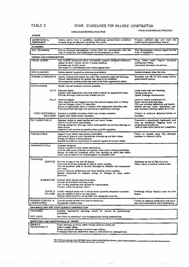
TABLE 2 SOME GUIDEUNES FOR HILLSIDE CONSTRUCfION0000 ENOlNEE:R.lNGPRACTICE POOR ENGINEERING PRACTICE
ADVICE
GEOTECHNICALASSESSMENT
Obtain advice from R qualified, experienced g80teclnical consultantat aorly stage of pllll'lning and before sl~e works.
Prepare detailed plan Rnd start siteworks before geoteclnlcal advice.
PL~SITE PLANNING Having obtained geateehnic:al advice. plan thl> davelopment with thll
Risk of I""tability and lmplioRtloos for Dev8lopmen~ in mind.Plan de""lapment withO-uY~ard lor theRisk 0 f Instability.
DESIGN At-D CCWSTRUCTION
HOUSE OESIGN Use flexible structurfls which incorporate properly designad brickwork, Floor plans which require extensivetimber or steel fram~, Umher or pllnel oladdlng. cutting and filling.Consider Ulle of split levels. Movllment Intolerant structures.Use decks for recreational areas where apprcpriate.
SITE CLEARING Retain natural vegetati .... Wherever practicable. Indllcrimiootely clear the alte.
ACCESS & DRIVEWAYS Satiefy requirements below for outs. flUs. retaining wans and drainage. Excavata and fill far site acceu beforeCouncil specifications for <;lt1ldesmay need to be modified. geateclnloal advloe.Driveways and parldng areal may need to be fully supported en pleN.
EARTHWORKS Retain natural contours wherever po.sible.
CUTS Minlml.e dep~. Large lcale cuts and benching.Support with engineered retaining walls or batter to appropriate elope. Ul)Supported cuts.Provide drainage m'! ... ures end erollon contro I. Ignore drainage requirement ••-,
FILLS Minimise height. - Loose or poorly compacted flU.Strip vegetation and topsoil and key Into natural .lop~ prior to fillIng, Block natural,drall\B!l" linea.Use and compact clean fill materials. Fill over existing vegetation and topsoil.Batter to appropriate slope or .~port with engineered retaining wall. Include stumps, trees. vegetation. top-Provld~ surface drainage and Appropriate stt>.urfaca drainage. soil. boulden, hulldi09 rubble eto (n fill.
ROCK OUTCROPS 3: Remove or .tah\lls8 bouldars which may btlCome unstable. Disturb or undercut detached blockll orBOULDERS Support rook feces whp.re necessary. boulders.
RETAINING WALLS Engineer design to resist applied eoil and water forces. Coostruot a Itructurelly inadequate wallF'ound on rnok where practicable. such as aandstone f1aqglng, brick orProvide slbstll'face d""ina98 within wall baokfiU and lurface d....lnage on unrelnfotced blockwork.•Iope abov". Lack of subsurface dmins and weepholes •Comtruct wall as soon II. possible after cut/fill operation.
F"OUNDA TlONS Support on or withln rock where practioable. Found on topsoil, lcose fill, detachedUIiElrows of piers or strip fOllndntiona oriented up Hnd down slope. boulders or tNldereut aliffs.Design for lateral creep pressures.Backfill foundation excavations to 1!l(Cludel09re.s of surface water.
SWIMMING POOLS Engineer designed.Support on piers to rock where practicable.Provide with under-drainage and qravity drllin outlet whero practicable.Design for hiqh soil pressures which may develop on uphill aide whilstthere may he little or I'll) lateral support on downhill side.
DRAINAGESURFACE Provioo at tops of cut and fill slopes. Dischargo at top of filii end cuts.
Discl>""ge to street drainage or natural water cOUT8es. Allow water to pond on bench areas.Provide generous falls to PfflVftOtblockage by siltation and incorporatesilt ~raps. .Line to minimiso infilt.ration and make f1eltible where posaible.Special structures to disipata energy at chenges of slope and/ordirection.
SU8SURFACE Provide filter around s,hsurface drain.Provide drain bohind ret<lining wall.,Use flexible pipelines with access for maintenanoe.Prevent inflow of surface water,
-,SEPTIC & Usually requires pump-ollt nr mains silwer syst.ems1 absorption trenches Discharge sullage directly onto and intoSULLAGE may be pnssihle in Stlme I.,w risk areas. slopes.
Storage tanks should be water-Ught and adequBtely foun1od.
EROSION CONTROL 3: Control ern.ion a. t.hinmny lead to instability. Failure to obsllrve earthworkl and drain-LANDSCAPING Revegetate cleared area. a90 rocommendatiol\! when landsoeplng.
DRAWINGS AID SITE VISITS ~G CONSTROCTION
DRAWINGS Buildin9 Application drawings should be viewed by geotechnicalconsultant.
SITE VISITS Sitp. Visih by r.ol\Sultant m"y be appropriate durl09 construction.
INSPECTION AN) MAINTENANCE BY Owro.F.ROWf\ER'S Clean drainll'J" systems; ropair broken joints In drair" endRESPONSIBILITY leaks in $lClPly pipes.
Where structural distre •• is evident .""k advice.If .eepsgo observed, determln" cause or leek advice on consequftncea.
'Tl\1t llhllb "" '~l".l fro .... ctOll:o-N!cAl. R15I<$ A5SOCtAT£O WITH H1L.L.~IDI: DI:VEl.OPME:NT.I p.... ntad I" Ay,\,.uon C•• m..,hanl ••Newt, Nvmbn 10, Uas. ......,IcbdUcuun tN mtL\.tr Mt:lJ'"t fuUy. .
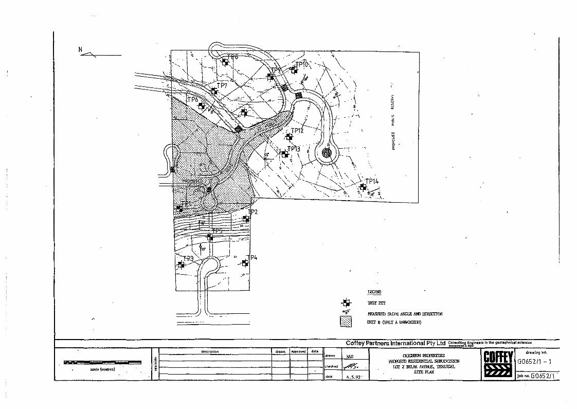
I
__ --/i l.'----------_/
-$-~[J]
MFMiURFDSI£lPE fIN;l..E Aro Dnm:ITCll
mill II (lltm: A Ul'i1A10~1l)
o
~o -go
Coffey Partners International Pty Ltd foneul::t ~in ..... in the geotechnical.cien ...
description drawn approved date COffEY drawing no.
:~drawn lll.s QUQIION Rll)FJ;RTIES
w PROroSID RESIDl'llrL\L SllBlM.sICll G0652/1 - 1.S: checked ~ lEIscale (metres' f TJJr 2 llEfJIR AVFNlE, 1ElRICAT.srm prAM
job no.G 065 21 1 .date >\.5.93·
Related Documents