Proportional Two-Stage Directional Valves High Performance with Main Stage Spool Feedback Pressures to 350 bar (5000 psi) KBFDG5V-5/7/8/10 Series

Welcome message from author
This document is posted to help you gain knowledge. Please leave a comment to let me know what you think about it! Share it to your friends and learn new things together.
Transcript
Proportional Two-Stage Directional Valves
High Performance with Main Stage Spool FeedbackPressures to 350 bar (5000 psi)
KBFDG5V-5/7/8/10 Series
3EATON Vickers Proportional Two-Stage Directional Valves KBFDG5V-5/7/8/10 V-VLDI-MC003-E2 February 2010
Introduction
General Description
Vickers proportional valvesshown in this catalog aresuitable for working pres-sures up to 350 bar (5000psi) and flow rates to 375l/min (99 USgpm).
They are designed to providea controlled oil flow in pro-portion to a command signal,with spool position feedbackto provide accurate control.
KBFDG5V-5/7/8/10
A range of proportional direc-tional valves with controlamplifiers built directly on,and prewired to the valves.Factory-set adjustments ofgain, spool deadband com-pensation, and offset ensurehigh valve-to-valve repro-ducibility.
The only electrical inputsrequired are power supply(24V) and a voltage com-mand signal of ±10V or 4-20mA. The amplifier is housedin a robust metal enclosure,sealed against ingress ofwater and other fluids.Electrical connections are viaa standard 7-pin plug.
A spool position monitorpoint allows the function ofthe valve to be electricallymonitored.
Features and Benefits
• Factory-sealed adjust-ments increase valve-to-valve reproducibility.
• Valve with integratedamplifier selected,ordered, delivered andinstalled as one perform-ance-tested package.
• Electronic feedback LVDTensures accurate spoolposition control.
• Vibration and shock tested.
• Standard 24V DC supplywith wide tolerance band.
• Wide range of spool andflow rate options.
• Standard ±10 V DC or 4-20 mA command signals.
• Installation wiring reducedand simplified.
• Standard 7-pin connector.
• Simple valve removal andreplacement for service.
• Supported by auxiliaryfunction modules.
• Full CE electromagneticcompatibility.
• IP65 and IP67 environmental protection rating.
• Optional valve enable function.
• On board ramp adjustment.
• Failsafe feature.
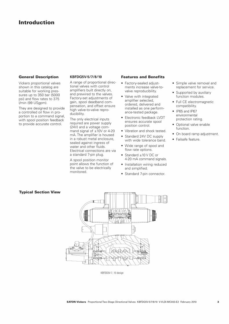
Typical Section View
KBFDG5V-7, 10 design
4 EATON Vickers Proportional Two-Stage Directional Valves KBFDG5V-5/7/8/10 V-VLDI-MC003-E2 February 2010
Model Code
Valve type
K – Proportional valve
Integral amplifier
B – Integral amplifier “B”series
Feed back arrangement
F – From main stage
Control type
D - Directional valve
Mounting
G – Subplate mounted
Operation
5 – Solenoid controlled, pilotoperated
Pressure rating
V – 310 bar (4500 psi) Size 05– 350 bar (5000 psi) Size 07– 350 bar (5000 psi) Size 08– 350 bar (5000 psi) Size 10
Interface
ISO 44015 – Size 057 – Size 078 – Size 0810 – Size 10
Spool type, flow ratingand metering
See “Functional Symbol” onpage 5. p = 5 bar (72 psi) permetering flow path, e.g. B to T.
Symmetric spools
For KBFDG5V-5 valves:
2C95N – 100 L/min (26 US gpm)
33C80N – 80 L/min (21 US gpm)
For KBFDG5V-7 valves:
2C200N – 200 L/min (52 US gpm)
33C160N – 160 L/min (42 US gpm)
For KBFDG5V-8 valves:
2C375N – 375 L/min (99 US gpm)
33C375N – 375 L/min (99 US gpm)
For KBFDG5V-10 valves:
2C700N – 700 L/min (185 US gpm)
33C700N – 700 L/min (185 US gpm)
Asymmetric spools
First figure (***N) is flowrating P-A, or A-T (“A” portflow); last figure (N***) is flow rating P-B, or B-T (“B” port flow)
For KBFDG5V-5 valves:
2C70N45 – 70 L/min (18.5 US gpm), “A” port flow45 L/min (11.9 US gpm), “B” port flow
33C60N40 – 60 L/min (17.2 US gpm), “A” port flow 40L/min (10.6 US gpm), “B” port flow
For KBFDG5V-7 valves:
2C150N85 – 150 L/min (40 US gpm), “A” port flow; 85 L/min (22.4 US gpm), “B” port flow
2C80N150 – 80 L/min (21 US gpm), “A” port flow;150 L/min (40 US gpm), “B” port flow
33C130N65 – 130 L/min (33.3 US gpm), “A” port flow;65 L/min (17.2 US gpm), “B” port flow
For KBFDG5V-8 valves:
2C375N250 – 375 L/min (99 US gpm), “A” port flow; 250 L/min (66 US gpm), “B” port flow
12C375N250 – 375 L/min (99 US gpm), “A” port flow; 250 L/min (66 US gpm), “B” port flow
33C375N250 – 375 L/min (99 US gpm), “A” port flow; 250 L/min (66 US gpm), “B” port flow
133C375N250 – 375 L/min (99 US gpm), “A” port flow; 250 L/min (66 US gpm), “B” port flow
733C375N250 – 375 L/min (99 US gpm), “A” port flow; 250 L/min (66 US gpm), “B” port flow
72C375N250 – 375 L/min (99 US gpm), “A” port flow; 250 L/min (66 US gpm), “B” port flow
For KBFDG5V-10 valves:
2C700N420 – 700 L/min (185 US gpm), “A” port flow; 420 L/min (110 US gpm), “B” port flow
33C700N420 – 700 L/min (185 US gpm), “A” port flow; 420 L/min (110 US gpm), “B” port flow
12C700N420 – 700 L/min (185 US gpm), “A” port flow; 420 L/min (110 US gpm), “B” port flow
133C700N420 – 700 L/min (185 US gpm), “A” port flow; 420 L/min (110 US gpm), “B” port flow
72C700N420 – 700 L/min (185 US gpm), “A” port flow; 420 L/min (110 US gpm), “B” port flow
733C700N420 – 700 L/min (185 US gpm), “A” port flow; 420 L/min (110 US gpm), “B” port flow
For actual maximum flowsrefer to power capacityenvelopes, page 8.
Pilot supply
X – Internal
EX– External
(Pilot drain - External ONLY)
Control signal
M1 – ±10V
M2 – 4-20mA
Electrical connection
PC7 – 7 pin connector withoutplug
PE7 – 7 pin connector with plug
PH7 – As PE7 but with pin“C” used for enable signal
PR7 – As PC7 but with pin“C” used for enable signal
Coil rating
H – 24 VDC amplifier supply
Pilot drain port
1 – 4 bar (58 psi)
Design number
10 – 10 series
12
15
14
13
11
10
9
8
7
6
5
4
3
2
1
K B F D G 5 V – * – ********* – (E)(X) – M* – P – H 1 – **
1 2 3 4 5 6 7 8 10 11 12 13 14 159
WARNING
Valves with integralamplifiers are sup-
plied with or without themetal 7-pin plug. The Vickersplug, part no. 934939, mustbe correctly fitted to ensurethat the EMC rating andIP67 rating are achieved. Theplug retaining nut must betightened with a torque of 2-2,5 Nm (1.5-2.0 lbf ft) toeffect a proper seal.

5EATON Vickers Proportional Two-Stage Directional Valves KBFDG5V-5/7/8/10 V-VLDI-MC003-E2 February 2010
Spool Data
Spool SymbolsSymmetric Spools
Base line pressure drop ∆p= 5 bar (72 psi) per meteringflow path, e.g. B to T. Foractual maximum flow referto power capacity envelopecurves.
Spool code Spool symbol Flow rating
For KBFDG5V-5 valves:
2C95N 2C 95 L/min (25 USgpm)33C80N 33C 80 L/min (21 USgpm)
For KBFDG5V-7 valves:
2C200N 2C 200 L/min (52 USgpm)33C160N 33C 160 L/min (42 USgpm)
For KBFDG5V-8 valves:
2C375N 2C 375 L/min (99 USgpm)33C375N 33C 375 L/min (99 USgpm)
For KBFDG5V-10 valves:
2C700N 2C 700 L/min (185 USgpm)33C700N 33C 700 L/min (185 USgpm)
Spool code Spool symbol Flow rating
For KBFDG5V-5 valves:
2C70N45 2C 70 L/min (18.5 USgpm) “A” port flow45 L/min (11.9 USgpm) ”B” port flow
33C60N40 33C 60 L/min (17.2 USgpm) ”A” port flow40 L/min (10.6 USgpm) ”B” port flow
For KBFDG5V-7 valves:
2C150N85 2C 150 L/min (40 USgpm) “A” port flow85 L/min (22.4 USgpm) ”B” port flow
2C80N150 2C 80 L/min (21 USgpm) ”A” port flow150 L/min (40 USgpm) ”B” port flow
33C130N65 33C 130 L/min (33.3 USgpm) “A” port flow65 L/min (17.2 USgpm) ”B” port flow
For KBFDG5V-8 valves:
2C375N250 2C 375 L/min (99 USgpm) “A” port flow250 L/min (66 USgpm) ”B” port flow
33C375N250 33C 375 L/min (99 USgpm) “A” port flow250 L/min (66 USgpm) ”B” port flow
12C375N250 12C 375 L/min (99 USgpm) “A” port flow250 L/min (66 USgpm) ”B” port flow
133C375N250 133C 375 L/min (99 USgpm) “A” port flow250 L/min (66 USgpm) ”B” port flow
72C375N250 72C 375 L/min (99 USgpm) “A” port flow250 L/min (66 USgpm) ”B” port flow
733C375N250 733C 375 L/min (99 USgpm) “A” port flow250 L/min (66 USgpm) ”B” port flow
For KBFDG5V-10 valves:
2C700N420 2C 700 L/min (185 USgpm) “A” port flow420 L/min (110 USgpm) ”B” port flow
33C700N420 33C 700 L/min (185 USgpm) “A” port flow420 L/min (110 USgpm) ”B” port flow
12C700N420 12C 700 L/min (185 USgpm) “A” port flow420 L/min (110 USgpm) ”B” port flow
133C700N420 133C 700 L/min (185 USgpm) “A” port flow420 L/min (110 USgpm) ”B” port flow
72C700N420 72C 700 L/min (185 USgpm) “A” port flow420 L/min (110 USgpm) ”B” port flow
733C700N420 733C 700 L/min (185 USgpm) “A” port flow420 L/min (110 USgpm) ”B” port flow
Spool Type and Flow Ratings
Asymmetric Spools
Figure preceding meteringtype designator, “N” e.g.2C**N) is flow rating P–A,or A–T (”A” port flow): Figureafter “N” (N***) is flow rating P–B, or B–T(”B” port flow).
Available Spools for
KBFDG5V
Spool type 2C
A B
P T
Spool type 33C
A B
P T
Spool type 72C
A B
P T
Spool type 733C
A B
P T
Spool type 133C
A B
P T
Spool type 12C
A B
P T
Application Notes
A. Main-Spool Options
Spools shown are meter-in/meter-out types. Center-condition options are types2, 33, 12, 133, 72 and 733.
B. Internally Piloted Models
Differ from detailed symbolsabove by omission of plug Aand the blocking of port X bythe mating surface.
Simplified Symbol
A B
P T
Functional Symbol
7-pinplug
Detailed Symbol
AT B
AT YP
AT BP
plug A plug B
P
11EATON Vickers Proportional Two-Stage Directional Valves KBFDG5V-5/7/8/10 V-VLDI-MC003-E2 February 2010
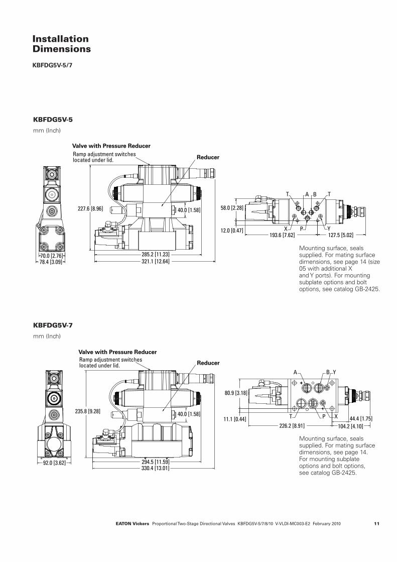
InstallationDimensions
KBFDG5V-5/7
Mounting surface, seals supplied. For mating surfacedimensions, see page 14 (size05 with additional X and Y ports). For mountingsubplate options and boltoptions, see catalog GB-2425.
KBFDG5V-5
mm (Inch)
KBFDG5V-7
mm (Inch)
A B
X P Y
T T
Ramp adjustment switches located under lid.
70.0 [2.76]78.4 [3.09] 321.1 [12.64]
227.6 [8.96] 40.0 [1.58] 58.0 [2.28]
193.6 [7.62] 127.5 [5.02]12.0 [0.47]
285.2 [11.23]
Valve with Pressure Reducer
Reducer
A B Y
XPT
92.0 [3.62] 294.5 [11.59]
40.0 [1.58]11.1 [0.44]
226.2 [8.91] 104.2 [4.10]
44.4 [1.75]
80.9 [3.18]
330.4 [13.01]
235.8 [9.28]
Ramp adjustment switches located under lid.
Valve with Pressure Reducer
Reducer
Mounting surface, seals supplied. For mating surfacedimensions, see page 14. For mounting subplateoptions and bolt options, see catalog GB-2425.
12 EATON Vickers Proportional Two-Stage Directional Valves KBFDG5V-5/7/8/10 V-VLDI-MC003-E2 February 2010
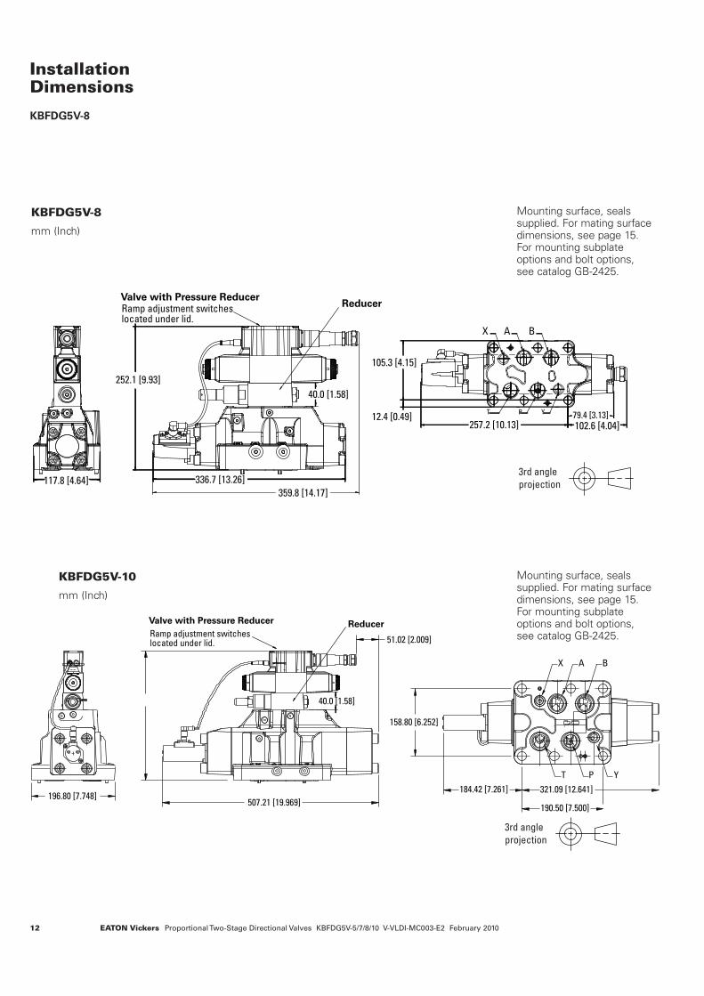
InstallationDimensions
KBFDG5V-8
KBFDG5V-8
mm (Inch)
KBFDG5V-10
mm (Inch)
Mounting surface, seals supplied. For mating surfacedimensions, see page 15. For mounting subplateoptions and bolt options, see catalog GB-2425.
X A B
T P Y
252.1 [9.93]
117.8 [4.64] 336.7 [13.26]
359.8 [14.17]
40.0 [1.58]
105.3 [4.15]
12.4 [0.49]257.2 [10.13]
79.4 [3.13]
102.6 [4.04]
Ramp adjustment switches located under lid.
Valve with Pressure ReducerReducer
184.42 [7.261]
190.50 [7.500]
321.09 [12.641]
T
X A B
P Y
Valve with Pressure ReducerReducer
Ramp adjustment switches located under lid.
196.80 [7.748]507.21 [19.969]
51.02 [2.009]
40.0 [1.58]
158.80 [6.252]
3rd angle
projection
Mounting surface, seals supplied. For mating surfacedimensions, see page 15. For mounting subplateoptions and bolt options, see catalog GB-2425.
3rd angle
projection
13EATON Vickers Proportional Two-Stage Directional Valves KBFDG5V-5/7/8/10 V-VLDI-MC003-E2 February 2010
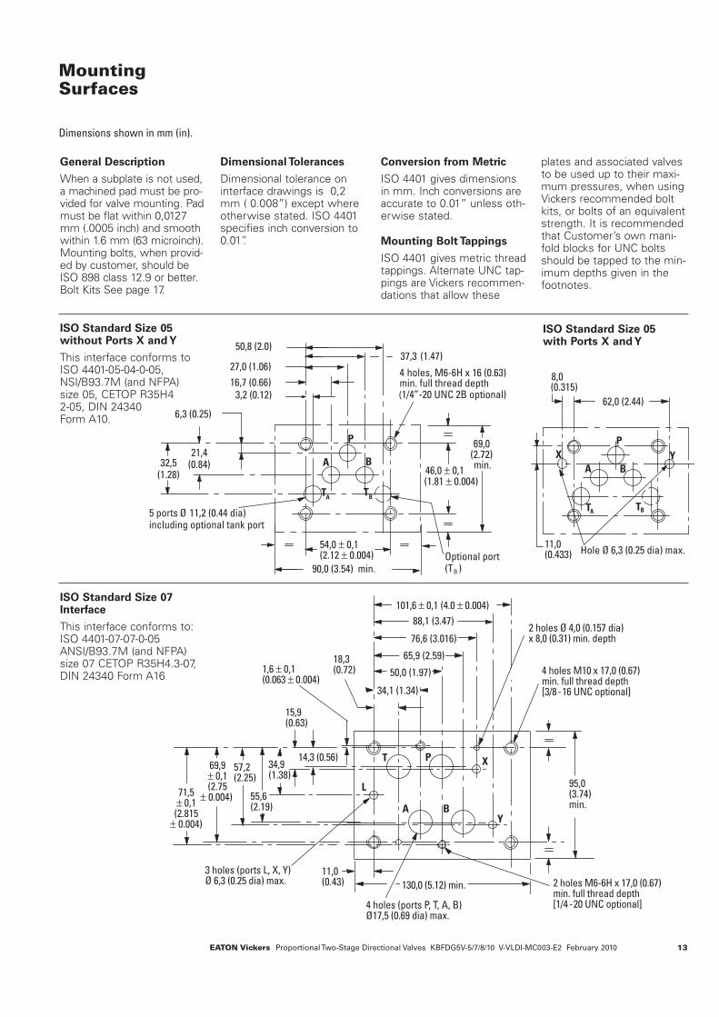
2 holes Ø 4,0 (0.157 dia)x 8,0 (0.31) min. depth
4 holes M10 x 17,0 (0.67)min. full thread depth[3/8-16 UNC optional]
2 holes M6-6H x 17,0 (0.67)min. full thread depth[1/4-20 UNC optional]
3 holes (ports L, X, Y)Ø 6,3 (0.25 dia) max.
4 holes (ports P, T, A, B)Ø 17,5 (0.69 dia) max.
95,0(3.74) min.
130,0 (5.12) min.
18,3(0.72)
34,1 (1.34)
50,0 (1.97)
65,9 (2.59)
76,6 (3.016)
88,1 (3.47)
101,6 ± 0,1 (4.0 ± 0.004)
1,6 ± 0,1(0.063 ± 0.004)
14,3 (0.56)
15,9(0.63)
71,5± 0,1(2.815
± 0.004)
PT
A B
X
Y
L
11,0(0.43)
69,9± 0,1(2.75
± 0.004)
57,2(2.25)
55,6(2.19)
34,9(1.38)
MountingSurfaces
Dimensions shown in mm (in).
General Description
When a subplate is not used,a machined pad must be pro-vided for valve mounting. Padmust be flat within 0,0127mm (.0005 inch) and smoothwithin 1.6 mm (63 microinch).Mounting bolts, when provid-ed by customer, should beISO 898 class 12.9 or better.Bolt Kits See page 17.
Dimensional Tolerances
Dimensional tolerance oninterface drawings is 0,2mm ( 0.008”) except whereotherwise stated. ISO 4401specifies inch conversion to0.01”.
Conversion from Metric
ISO 4401 gives dimensionsin mm. Inch conversions areaccurate to 0.01” unless oth-erwise stated.
Mounting Bolt Tappings
ISO 4401 gives metric threadtappings. Alternate UNC tap-pings are Vickers recommen-dations that allow these
plates and associated valvesto be used up to their maxi-mum pressures, when usingVickers recommended boltkits, or bolts of an equivalentstrength. It is recommendedthat Customer’s own mani-fold blocks for UNC boltsshould be tapped to the min-imum depths given in thefootnotes.
ISO Standard Size 05 without Ports X and Y
This interface conforms toISO 4401-05-04-0-05,NSI/B93.7M (and NFPA) size 05, CETOP R35H4 2-05, DIN 24340 Form A10.
ISO Standard Size 05 with Ports X and Y
37,3 (1.47)
5 ports Ø 11,2 (0.44 dia)including optional tank port
27,0 (1.06)
16,7 (0.66)
6,3 (0.25)
3,2 (0.12)
50,8 (2.0)
46,0 ±(1.81 ± 0.004)
0,132,5
(1.28)
90,0 (3.54) min.
P
A B
TA
TB
54,0 ± 0,1(2.12 ± 0.004)
69,0(2.72)min.
21,4(0.84)
Optional port (TB )
4 holes, M6-6H x 16 (0.63)min. full thread depth (1/4”-20 UNC 2B optional)
P
A
TATB
62,0 (2.44)
8,0(0.315)
11,0(0.433)
X
Hole Ø 6,3 (0.25 dia) max.
Y
B
ISO Standard Size 07Interface
This interface conforms to:ISO 4401-07-07-0-05ANSI/B93.7M (and NFPA)size 07 CETOP R35H4.3-07,DIN 24340 Form A16
Related Documents


